7-3
Error Code Definitions and Solutions: Codes [1000 — 1999]
7-3-1
Error Code [1102]
1. Error code definition
Discharge temperature fault
2. Error definition and error detection method
1) If the discharge temperature of 120 °C [248°F] or more is detected during the above operation (the first detection), the outdoor
unit stops once, turns to anti-restart mode for 3 minutes, and restarts after 3 minutes automatically.
2) If the discharge temperature of 120° C [248°F] or more is detected again (the second detection) within 30 minutes after the
second stop of the outdoor unit described above, the mode will be changed to 3 — minute restart mode, then the outdoor unit
will restart in 3 minutes.
3) If the discharge temperature of 120°C [248°F] or more is detected (the 30th detection) within 30 minutes after the stop of the
outdoor unit described above (regardless of the first or the 29th stop), the outdoor unit will make an error stop, and the error
code «1102» will be displayed.
4) If the discharge temperature of 120°C [248°F] or more is detected more than 30 minutes after the previous stop of the outdoor
unit, the detection is regarded as the first detection, and the operation described in step 1 above will start.
5) For 30 minutes after the stop (the first stop or the second stop) of the outdoor unit, preliminary errors will be displayed on the
LED display.
3. Cause, check method and remedy
(1)
Gas leak, gas shortage
(2)
Overload operation
(3)
LEV failure on the indoor unit
(4)
Outdoor unit LEV1 actuation failure
Outdoor unit LEV2 actuation failure
(5)
Closed refrigerant service valve
(6)
Outdoor fan (including fan parts) failure, mo-
tor failure, or fan controller malfunction
Rise in discharge temp. by low pressure
drawing for (3) — (6).
(7)
Gas leak between low and high pressures
(4-way valve failure, Compressor failure, So-
lenoid valve (SV1a) failure)
(8)
Thermistor failure
(TH4)
(9)
Input circuit failure on the controller board
thermistor
HWE14040
Cause
Check method and remedy
Refer to the following page(s).[6-9 Evaluating and Adjusting
Refrigerant Charge](page 131)
Check operating conditions and operation status of indoor/
outdoor units.
Perform a cooling or heating operation to check the opera-
tion.
Cooling: Indoor unit LEV, LEV1, LEV2
Heating: Indoor unit LEV, LEV2
Refer to the following page(s). [8-8 Troubleshooting LEV
Problems](page 258)
Confirm that the refrigerant service valve is fully open.
Check the fan on the outdoor unit.
Refer to the following page(s). [8-7 Troubleshooting Outdoor
Unit Fan Problems](page 257)
Perform a cooling or heating operation and check the opera-
tion.
Refer to the following page(s).
Check the inlet air temperature on the LED monitor.
— 171 —
GB
Коды ошибок неисправностей кондиционеров Mitsubishi Electric
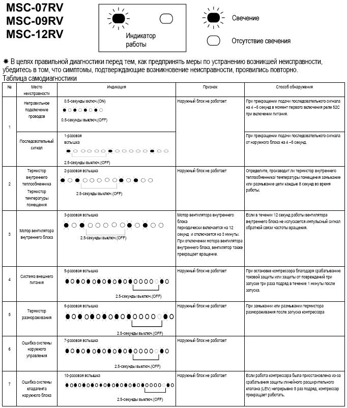
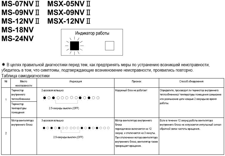
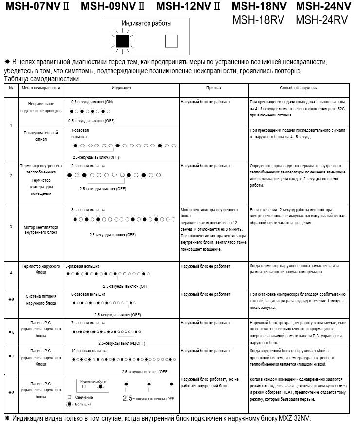
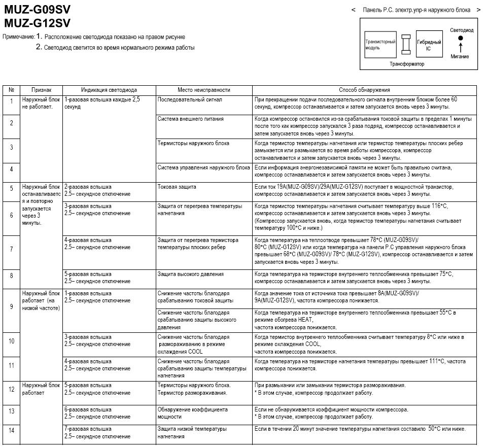
В таблицу включены коды ошибок кондиционеров Mitsubishi Electric серии М (слева направо):
- MSC-07/09/12RV
- MS-07/09/12/18/24NV (II), MSX-05/09/12NV
- MSH-07/09/12/18/24NV (II) / RV
- MSZ-G09/G12SV
- MSZ-G09/G12SV <Панель Р.С. электронного управления наружного блока>
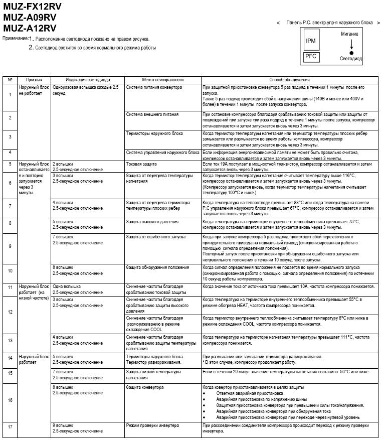
- MSZ-FX12RV, MSZ-A09/A12RV
- MSZ-FX12RV, MSZ-A09/A12RV <Панель Р.С. электронного управления наружного блока>
Важно! В целях правильной диагностики перед тем, как предпринять меры по устранению возникшей неисправности, убедитесь в том, что симптомы, подтверждающие возникновение неисправности, проявились повторно.
Продажа и монтаж. Ремонт и обслуживание (Пн.-пт.: 09.00—19.00, сб-вс: 10.00-17.00):
+7(495) 146-65-64
sale@service-climate.ru

Коды ошибок сплит-систем Mitsubishi Electric
Коды ошибок кондиционеров Mitsubishi Electric отображают на табло следующую информацию:
Таблица расшифровки кодов ошибок
|
Error |
Расшифровка | Русский перевод |
| P1 | Intake sensor error | Ошибка датчика на входе |
| P2 | Pipe (TH5) sensor error | Ошибка датчика теплообменника ТН5 (по схеме) |
| P4 | Drain sensor error/Float switch connector (CN4F) open | Переполнение дренажного поддона, или обрыв поплавкового датчика CN4F |
| P5 | Drain pump error | Ошибка дренажной помпы |
| P6 | Freezing/Overheating protection operation | Ошибка по обмерзанию или перегреву |
| P8 | Pipe temperature error | |
| P9 | Pipe (TH2) sensor error | Ошибка по датчику теплообменника ТН2 |
| PA | Forced compressor stop(due to water leakage abnormality) | Принудительная остановка компрессора (из-за переполнения дренажной системы) |
| E0, E3 | Remote controller transmission error | Нет связи с пультом управления |
| E1, E2 | Remote controller control board error | Неисправна плата пульта управления |
| E4, E5 | Remote controller signal receiving error | |
| E9 | Indoor/outdoor unit communication error (Transmitting error) (Outdoor unit) | Нет связи между внутренним и внешним блоком (Ошибка на внешнем блоке) |
| EE | Communication error between indoor and outdoor units | Отсутствует межблочная связь между внутренним и внешним блоками |
| U1,Ud | Abnormal high pressure (63H worked)/Overheating protection operationс | Высокое давление по датчику 63Н, или защита от перегрева |
| U2 | Abnormal high discharging temperature/49C worked/insufficient refrigerant | Сработал датчик 49С, очень низкое давление нагнетания, недостаток хладагента |
| U3, U4 | Open/short of outdoor unit thermistors | Обрыв, короткое замыкание термодатчика внешнего блока |
| U5 | Abnormal temperature of heat sink | Температура конденсатора не соответствует норме |
| U6 | Compressor overcurrent interruption/Abnormal of power module | Компрессор принудительно остановлен по токовой перегрузке, неисправен силвой модуль |
| U7 | Abnormality of super heat due to low discharge temperatureAbnormal high discharging temperature/49C worked/insufficient refrigerant | Сработал датчик 49С / очень низкое давление нагнетания / недостаток хладагента |
| U8 | Outdoor unit fan protection stop | Двигатель вентилятора внешнего блока остановлен |
| U9, UH | Abnormality such as overvoltage or voltage shortage and abnormal synchronous signal to main circuit/Current sensor error | Повышенное / пониженное напряжение питания, неисправность токового датчика |
| UF | Compressor overcurrent interruption (When compressor locked) | Компрессор остановлен из-за токовой перегрузки, компрессор заклинило |
| UP | Compressor overcurrent interruption | Остановка компрессора из-за перегрузки по току |
| Fb | Indoor unit control system error (memory error, etc.) | Ошибка платы управления внутреннего блока (EEPROM и т.д.) |
Коды ошибок бытовых Сплит-систем
Определить ошибку в бытовых сплит системах можно по миганию индикаторов на панели внутреннего блока.
Для моделей:
MSC-GE20VB
MSC-GE25VB
MSC-GE35VB
MS-GE50VB
MSH-GE20VB
MS-GA60VB
MS-GD80VB
MSH-GA60VB
MSH-GD80VB
| Ошибка | Расшифровка кода ошибки | Устранение ошибки |
| E— | Просмотр сохраненных сообщений об ошибках. | |
| HOLD | Блокировка панели управления. |
|
| LOCD | Защищено паролем. |
|
| Er1 | Ошибка при передаче параметров. |
|
| Er2 |
|
|
| Er3 |
|
|
| Er4 |
|
|
| Err. | Сброс частотного преобразователя. |
|
Предупреждающие коды частотного преобразователя Mitsubishi
| Ошибка | Расшифровка кода ошибки | Устранение ошибки |
| OL | Защита двигателя от опрокидывания активирована (в следствии тока перегрузки). |
|
| oL | Защита двигателя от опрокидывания активирована (в следствии превышения напряжения на промежуточном контуре). |
|
| rB | Перегрузка на тормозном сопротивлении. |
|
| TH | Предварительный сигнал тревоги электрической защиты двигателя от перегрева. | |
| PS | Останов частотного преобразователя был произведён через панель управления. |
|
| MT | Сообщение о необходимости проведения работ по техобслуживанию. |
|
| UV | Превышено максимально допустимое напряжение. |
|
| SA | Безопасный останов. |
|
Коды ошибок частотного преобразователя Mitsubishi (серьезные неисправности)
| Ошибка | Расшифровка кода ошибки | Устранение ошибки |
| Fn | Вентилятор не исправен. |
|
| E.OC1 | Отключение по превышению тока при разгоне. |
|
| E.OC2 | Отключение по превышению тока при постоянной скорости вращения. |
|
| E.OC3 | Отключение по превышению тока в процессе торможения или останова. |
|
| E.OV1 | Превышение напряжения при разгоне. |
|
| E.OV2 | Превышение напряжения при постоянной скорости вращения. |
|
| E.OV3 | Превышение напряжения в процессе торможения или останова. |
|
| E.THT | Защита от перегрузки (частотный преобразователь). |
|
| E.THM | Защита электродвигателя от перегрузки (срабатывание электрической тепловой защиты). |
|
| E.FIN | Перегрев радиатора. |
|
| E.ILF* | Рассогласование входных фаз. |
|
| E.OLT | Отключающая защита от опрокидывания двигателя. |
|
| E. BE | Неисправность встроенного тормозного транзистора. Неисправность во внутреннем электрическом контуре. |
|
| E. GF | Ток перегрузки вследствие замыкания на землю. |
|
| E. LF | Ошибка выходной фазы |
|
| E.OHT | Срабатывание внешней тепловой защиты двигателя (термоконтакта) |
|
| E.PTC* | Срабатывание термистора с ПТК |
|
| E. PE | Ошибка запоминающего устройства |
|
| E.PUE | Неисправность соединения с панелью управления |
|
| E.rET | Превышение допустимого количества попыток перезапуска |
|
| E. 5 | Ошибка центрального процессора |
|
| E.CPU | ||
| E.CDO* | Превышение допустимого выходного тока |
|
| E.IOH* | Перегрев сопротивления включения |
|
| E.AIE* | Неисправный аналоговый вход |
|
| E.SAF* | Ошибка в защитном контуре |
|
Коды ошибок кондиционеров Mitsubishi Electric отображают на табло следующую информацию:
MSC-GE20VB
MSC-GE25VB
MSC-GE35VB
MS-GE50VB
MSH-GE20VB
MS-GA60VB
MS-GD80VB
MSH-GA60VB
MSH-GD80VB
Скачать: Коды ошибок сплит-систем_mitsubishi_electrik
Поиск неисправности Mitsubishi Electric отображают на табло следующую информацию:
Скачать PDF: Поиск неисправности_mitsu_electrik
Mitsubishi Electric Corporation was established in 1921 and worked its way to becoming a leading multinational electrical equipment and electronics manufacturer. With its headquarters in Tokyo, there was a time the company only focused on elevators, escalators, and high-end appliances such as air conditioners. While the company has grown, these three remain to be their top candidates.
When it comes to air conditioning the company offers ac systems such as room air conditioners, package air conditions, VRF systems, Ventilators, air curtains, and so on. Along with endless home and commercial appliances that start with toasters and ends with elevators and moving walks. With its main focus on air conditioners, Mitsubishi is one of the leading designers, manufacturers, and providers in the world. Yet, there are times when customers find themselves baffled by a random code on their appliance.
To help you out we have listed down some of the most common error codes for Mitsubishi Air conditioners. Start by noting down the error code, and match it using the list below. Once you have the error code you can understand the main issue with your Mitsubishi air conditioner, and draw out a solution that works to your advantage.
Mr Slim P Series (A)
Mr. Slim P-Series ductless heat pumps and air conditioners are compact yet powerful, offering unrivaled energy efficiency and design flexibility. Their advanced technology has been designed and tested to withstand the extremes of the Canadian climate in order to deliver a reliable and proven climate control system that you can trust all year round. With a variety of models to choose from, there’s a P-Series solution for any commercial application.
| Fault Codes | Problem |
|---|---|
| A0 | Duplicate address — Lossnay units attached with the same address — change addresses and reset the units power |
| A2 | Hardware error of transmission processor (Lossnay) — check comms wiring, and for possible Lossnay board fault |
| A3 | Line busy no data could be transmitted for 8 minutes — check A- M-Net connections (TB7 and TB3) |
| A6 | Communication error with communication processor — Lossnay address not transmitted — check M-Net voltage |
| A7 | No ACK signal — check A- M-Net wiring, range of transmission wiring exceeded or if faulty A- M-Net converter |
| A8 | M-Net no response — check A- M-Net wiring, range of transmission wiring exceeded, faulty A- M-Net converter or if incorrect wire used for M-Net connection |
| EA | Mis-wiring/loose inter-connecting cables. Noise interference |
| EB | Mis-wiring/loose interconnecting cables. Noise interference. Wrong cable size/spec |
| EC | Start-up time over. The unit has failed to initialise after power up. Noise interference. Wrong cable size/spec |
| ED | Serial communication error. Comms error between boards on outdoor unit caused by M-Net interface board incorrectly fitted |
| EF | Non-defined error code. Noise interference — power down outdoor unit for 30 seconds then switch back on |
| E0 | Remote controller communication error — check wiring, connections and comms voltage. Also check Master/Slave settings if multiple systems are connected |
| E1 | Remote controller issue — if grouped, check addressing. If twinned, check wired to master indoor only |
| E2 | Remote controller issue — if grouped, check addressing. If twinned, check wired to master indoor only |
| E3 | Remote controller issue — not transmitting — if grouped, check addressing. If twinned check wired to master indoor only |
| E4 | Remote controller issue — not receiving — if grouped, check addressing. If twinned, check wired to master indoor only |
| E5 | Remote controller issue — not receiving — if grouped, check addressing. If twinned, check wired to master indoor only |
| E6 | Indoor/outdoor communication error, mainly caused by outdoor unit being powered up before indoor unit. Drain pump being wired into S1 and S2 causes interference |
| E7 | Comms fault between I/C and O/C — check for condensate pump at I/C, reset power to O/C, check 12/24Vdc on S2 and S3 possible I/C board failure |
| E8 | Comms failure indoor to outdoor (S2/S3) — check pumps wired in, check indoor isolator and re-power in the correct sequence i.e. indoor then outdoor |
| E9 | Comms failure indoor to outdoor (S2/S3) — check pumps wired in, check indoor isolator and re-power in correct sequence i.e. indoor then outdoor |
| FA | 51CM connector open — check thermal relay for disconnection or contact failure. Possible defective board |
| F1 | Reverse phase detection — check power supply, try swapping 2 phases round. Possible defective board |
| F2 | L3 phase open — check power supply, also check for open circuit protection devices |
| F3 | 63L open — check low pressure switch for disconnection or contact failure. Possible defective board |
| F4 | 49C open — compressor inner thermostat for open circuit or contact failure |
| F5 | 63H open — check high pressure switch for disconnection or contact failure. Possible defective board |
| F7 | Phase detection circuit fault — faulty outdoor board |
| F8 | No input detected at outdoor unit — outdoor board defective |
| F9 | Two or more protection devices are open — check protection devices for disconnection or contact failure |
| P1 | Return air thermistor fault (TH1) — check if TH1 disconnected or open or close circuit |
| P2 | Liquid pipe thermistor fault (TH2) check if TH2 disconnected or open or close circuit |
| P4 | Drain sensor fault — DS open or close circuit |
| P5 | High condensate level — drain pump failure or blockage in the drain |
| P6 | Freezing/Overheating of indoor unit heat exchanger — mainly caused by reduced air flow through indoor coil. Dirty filters. Fan motor problem. Blockage |
| P8 | Abnormal pipe temperature — mainly caused by refrigerant leakage. Possibility that the thermistor mounted incorrectly |
| P9 | TH5 condenser/evaporator thermistor open/close circuit. Disconnected from the board |
| U1 | High pressure trip — outdoor fan failure, blocked coil, blockage in the system, blocked filters on indoor in heating etc |
| U2 | High discharge temperature — compressor over heating due to lack of refrigerant, faulty thermistor, high ambient running conditions. Can also be caused by 49C (comp inner thermostat or external Klixon ) tripping |
| U3 | Discharge thermistor fault |
| U4 | Outdoor thermistor fault |
| U5 | Inverter heat sink temperature too high (TH8) — check for lack of air flow around heat sink, no silicone paste, faulty thermistor (temperature can be read from service tool (or PAR21 on power inverter model)) |
| U6 | Compressor over current — carry out inverter output test and electrical checks to the compressor |
| U7 | Low discharge superheat — check TH4 reading is correct. Check LEV operations |
| ho | -For about 2 minustes following power-on, operation of the remote controller is not possible deu to system start-up. — Connector for the outdoor unit’s protection device is not connected. -Reserve or open phase wiring for the outdoor unit’s power terminal block (L1,L2,L3). -Incorrect wiring between indoor and outdoor units (incorrect polarity of S1,S2,S3). -Remote controller wire short. |
| FFFF | No unit. Buzzer sound: Triple beep. Operation Led: No lit. |
| U0-UP | Outdoor unit error. |
| F1-FA | Outdoor unit error. |
| E0-E5 | Signal error between remote controller and indoor units. |
| E6-EF | Communication error between indoor and outdoor units. |
| — | No alarm history. |
Mr Slim P Series (K)
Mr. Slim P-Series is the ductless solution for demanding environments that require an efficient and reliable heating or cooling system. P-Series ductless systems are stylish, compact, and more attractive than traditional systems. Advanced technology also means your Mr. Slim ductless system will run more efficiently than a conventional unit, saving you from rising energy costs.
| Fault Codes | Problem |
|---|---|
| EO | System transmission error — check for possible comms fault between I/C and R/C, could also be incorrect group or master/slave settings (check CN40, SW2 and SW6) |
| P1 | TH1 fault — check return air thermistor (6.4K_ @ 20°C) |
| P2 | TH2 fault — check coil/pipe thermistor (6.4K_ @20°C) |
| P3 | System transmission error — check for possible comms fault between I/C and R/C, could also be incorrect group or master/slave settings (check CN40, SW2 and SW6) |
| P4 | Drain sensor fault — check drain sensor resistance, connection and continuity |
| P5 | Drain fault — unit has detected high condensate — check for blockage in drain or tray, pump failure or sensor fault |
| P6 | Frost protection in cooling/Overheat protection in heating — detected by indoor coil sensor — general causes are lack of air flow or refrigerant charge problem |
| P7 | System error — address setting fault — check CN40 SW2 and SW6. Potential board issue |
| P8 | Abnormal pipe/coil temperature — no temperature change at indoor unit after 9 minutes of operation. General causes are outdoor unit tripped, problem with refrigerant charge or lack of air flow at the indoor unit. TH2 faulty or not mounted correctly |
| LD1 | Reverse phase on mains supply — change phases around, check for potential board problem |
| LD2 | Component open circuit — check CH, 52C, 21S4, SV, 63H and 26C for open circuit or disconnected |
| LD3 | Outdoor coil thermister is open or short circuit may be disconnected or outdoor board fault |
| LD4 | 63H high pressure switch open — investigate high pressure causes, 63H switch disconnected |
| LD5 | 51CM overcurrent relay open — compressor locked or pulling too much current — check power supply |
| LD6 | 26C thermal switch open — check if refrigerant level low or if 26C is disconnected |
| LD7 | Overheat protection — coil temp has exceeded 67°C — reduced airflow through condenser — check for fan motor problem or thermistor problem |
| LD8 | Input circuit of outdoor board — replace the outdoor board |
Multi City VRF
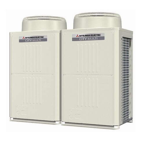
The CITY MULTI S series (for small applications) and Y series (for large applications) make use of a two-pipe refrigerant system, which allows for system changeover from cooling to heating, ensuring that a constant indoor climate is maintained in all zones.
| Error Codes | Problem |
|---|---|
| 403 | Comms fault between boards — check inverter error detail for which 2 boards, check transformer, bus voltage and inter-connecting cables |
| 900 | Lossnay unit in test run |
| 1102 | High compressor discharge temperature. Discharge temperature has exceeded 110°C or more. Short of refrigerant. Discharge thermistor |
| 1111 | Low pressure/temperature fault — check thermistors (TH2, TH3, TH4), gas charge, indoor fan, heat exchanger and filter |
| 1112 | Low pressure/temperature fault — check thermistors (TH2, TH3, TH4), gas charge, indoor fan, heat exchanger and filter |
| 1113 | Low pressure/temperature fault — check thermistors (TH2, TH3, TH4), gas charge, indoor fan, heat exchanger and filter |
| 1202 | Preliminary fault to 1102 |
| 1204 | Preliminary heat exchanger gas temperature sensor fault — check thermistors 10a and 10b |
| 1205 | Preliminary thermistor fault (TH5) |
| 1211 | Preliminary thermistor fault (TH2) |
| 1214 | Preliminary thermistor fault (THHS) |
| 1216 | Preliminary thermistor fault (TH7) |
| 1217 | Preliminary thermistor fault (TH8) |
| 1219 | Preliminary thermistor fault (TH9) |
| 1221 | Preliminary thermistor fault (TH6) |
| 1243 | Preliminary thermistor fault (TH10) |
| 1301 | Low pressure fault (63L operation) low pressure sensor sensing less than 1 bar immediately before starting |
| 1302 | High pressure fault — check pressure in system for more than 29 bar (R407c) 38 bar (R410A). Check high pressure sensor against gauge pressure |
| 1368 | Pressure sensor fault (PS1) at BC — compare pressure reading on SW1 on O/C |
| 1370 | Pressure sensor fault (PS3) at BC — compare pressure reading on SW1 at O/C |
| 1402 | Preliminary fault to 1302 |
| 1500 | System overcharge. Abnormal low compressor superheat — discharge thermistor TH4 |
| 1501 | High compressor shell temp — check for shortage of gas, insufficient indoor index running (comms room units) |
| 1505 | Suction pressure abnormal — generated by low pressure sensor detecting a vacuum — check for blockage, closed valve or sensor fault |
| 2500 | Detecting lack of water flow on a water circuit |
| 2502 | I/C has water level in drip tray, when the unit was running in cooling (temperature sensors — check for open or closed circuit and operation of pump) |
| 2503 | I/C has water level in drip tray when the unit was running in cooling (float sensor — check for closed circuit on float switch and operation of pump) |
| 2600 | Water leak from humidifier |
| 4100 | Compressor over current protection on Mr Slim with M-net interface — check inverter or compressor |
| 4101 | Compressor over current protection on Mr Slim with M-net interface — check inverter or compressor |
| 4102 | Open phase fault — check power supply and noise filter for loss of phase, check wiring and fuses |
| 4103 | Reverse phase fault — check phase rotation, loss of phase through the noise filter, fuse blown and high pressure switch open at power on |
| 4106 | Transmission power supply fault — check wiring, high current, incorrect voltage on transmission line and/or M-Net board |
| 4108 | Over current protection on DOL compressor — check power supply, contactor and compressor |
| 4115 | Power supply abnormal — check power, fuses, connections and PCB |
| 4116 | Fan motor abnormal — check fan motor and board (relates to indoor unit or Lossnay unit) |
| 4124 | Thermal switch (49C) open circuit on Mr Slim on M-Net — reset and check pressures and air flow |
| 4210 | Compressor over current problem — check inverter balance. Compressor and inverter |
| 4220 | Low inverter board BUS voltage. Less than 289VdcDC is detected. — check mains supply |
| 4225 | Low DC voltage on Vdc on fan inverter — check CNVdc for 300Vdc on diode stack and check mains power supply to outdoor unit |
| 4230 | High temperature on heat sink on inverter — check for blockages in air duct, failure of INV fan or failure of thermistor |
| 4235 | Fan inverter heat sink overheat protection. Reduced airflow through heat sink. Fan motor problem. THHS thermistor problem |
| 4240 | Over current protection. If high current is detected for more than 10 minutes — check inverter balance. Reduced airflow through heat sink |
| 4245 | Over current protection. Possible ACCT current sensor fault. Should read 280 ohms between pins 1 & 2 and across pins 3 & 4 |
| 4250 | Over current protection. Inverter IPM problem. Compressor lock — check inverter balance |
| 4255 | Inverter cooling fan problem — if high static fan is used then check that SW3-9 is on |
| 4260 | Preliminary inverter heat sink overheat protection. Reduced airflow through heat sink. Fan motor problem. THHS thermistor problem |
| 5101 | Thermistor fault at indoor/outdoor unit — check fault code address |
| 5102 | Thermistor fault at indoor/outdoor unit — check fault code address |
| 5103 | Thermistor fault at indoor/outdoor unit — check fault code address |
| 5104 | Thermistor fault at indoor/outdoor unit — check fault code address (indoor fault — check SW7-3 is off) |
| 5105 | TH5 open/short circuit — check if the TH is disconnected from the board |
| 5106 | TH6 open/short circuit — check if the TH is disconnected from the board |
| 5107 | TH7 open/short circuit — check if the TH is disconnected from the board |
| 5108 | TH8 open/short circuit — check if the TH is disconnected from the board |
| 5109 | TH9 open/short circuit — check if the TH is disconnected from the board |
| 5110 | TH10 open/short circuit — check if the TH is disconnected from the board |
| 5111 | BC box thermistor error — TH11 open/short circuit, disconnected from board/pipe |
| 5112 | BC box thermistor error — TH10 open/short circuit, disconnected from board/pipe |
| 5113 | BC box thermistor error — TH open/short circuit, disconnected from board/pipe |
| 5114 | BC box thermistor error — TH open/short circuit, disconnected from board/pipe |
| 5115 | BC box thermistor error — TH15 open/short circuit, disconnected from board/pipe |
| 5116 | BC box thermistor error — TH16 open/short circuit, disconnected from board/pipe |
| 5201 | Pressure sensor fault outdoor unit/BC box — check fault code address/SW1 pressure sensor readings |
| 5202 | Pressure sensor fault (PS2) in the BC box |
| 5203 | Pressure sensor fault (PS3) in the BC box |
| 5300 | A-Control UH fault — see Mr Slim fault code list |
| 5301 | Current sensor fault, ACCT or DCCT — check inv. error details |
| 5401 | Temperature sensor fault — check CN30 for humidity sensor |
| 5701 | Loose float switch connector — check switch, check CN4F on indoor unit |
| 6201 | TB7 transmission line communication error — check for voltage abnormality/short |
| 6202 | Transmission processor hardware error — check for noise/short on M-Net cable |
| 6600 | Repeat address fault — two or more units are assigned the same address — correct the repeated address |
| 6601 | Polarity setting error — no voltage or short circuit on the m-net transmission line |
| 6602 | Hardware error of transmission processor. Noise interference. Polarity problem on TB7 |
| 6603 | Bus circuit busy — check if indoor unit, Lossnay unit or anything else has been wired into TB7, instead of TB3 |
| 6607 | Communication issue — no response back from unit whilst system is operational |
| 6608 | Communication error — loss of voltage or noise entering the transmission line |
| 6700 | K control communication error — R22 type unit connected onto M-Net circuit comms error |
| 6701 | K control communication error — R22 type unit connected onto M-Net circuit comms error |
| 6702 | K control duplicate address error — two or more R22 type units connected onto M-Net circuit with the same address |
| 6750 | K control communication error — R22 type unit connected onto M-Net circuit comms error |
| 6751 | R22 R/A thermistor fault (P1) |
| 6752 | R22 frost protection at I/C (P6) |
| 6753 | Comms fault between O/C and I/C |
| 6754 | R22 drain fault (P5) |
| 6755 | R22 drain fault (P5) |
| 6756 | R22 frost protection at I/C (P6) |
| 6757 | System error |
| 6758 | Comms fault between I/C and O/C |
| 6761 | R22 R/A thermistor fault (P1) |
| 6762 | R22 TH2 fault check resistance (P2) |
| 6763 | R22 Comms fault between I/C and O/C |
| 6764 | R22 drain fault (P4) |
| 6765 | R22 drain fault (P5) |
| 6766 | R22 frost protection at I/C (P6) |
| 6767 | R22 comms fault between I/C and O/C |
| 6771 | K abnormality — high pressure abnormality or low pressure abnormality |
| 6772 | K abnormality — inner thermostat function, discharge temperature abnormality, shell thermostat function, over current protection |
| 6773 | K abnormality — radiator plate thermostat function |
| 6774 | K abnormality — outdoor thermistor abnormality |
| 6775 | K abnormality — pressure sensor abnormality, indoor/outdoor communication error |
| 6776 | K abnormality — over current shut-off |
| 6777 | K abnormality — system error |
| 6778 | K abnormality — normal |
| 6779 | K abnormality — refrigerant overcharge, abnormal voltage, abnormal CT sensor |
| 6830 | Comms fault between I/C and R/C check connections to MA R/C and check for 12Vdc check R/C not set sub controller |
| 6831 | MA R/C communication fault — check connections on TB15 or that the controller was removed while the I/C was powered |
| 6832 | MA controller comms fault — check cable length no bigger than 500m, check connection and type of cable used, check R/C not set sub on field settings |
| 6833 | MA controller comms fault check cable length no bigger than 500m, check connection and type of cable used, check R/C not set sub on field settings |
| 6834 | MA Controller comms fault — check cable length no bigger than 500m, check connection and type of cable used, check R/C not set sub on field settings |
| 6840 | A-Control E6/E8 fault — see Mr Slim fault code list |
| 6841 | A-Control E7/E9 fault — see Mr Slim fault code list |
| 6844 | A-Control EA fault — see Mr Slim fault code list |
| 6845 | A-Control Eb fault — see Mr Slim fault code list |
| 6846 | A-Control EC fault — see Mr Slim fault code list |
| 7100 | Over capacity — (R2 150% index exceeded) (Y 130% index exceeded) |
| 7101 | Capacity setting error — SW2 set wrong on indoors, SW5 on YHMA outdoor, (SW3-10 on older kit) |
| 7102 | Error in number of connected units — loss of M-Net voltage (short or break), no power to BC, wrong SW5 setting on box, wrong box type |
| 7105 | Address setting error — OC or BC addressed wrong |
| 7106 | Attribute setting error — SW3-1 setting on a GUF |
| 7107 | Port setting error — check if too much capacity on a single port, wiring SW2 setting, wrong SW14 setting or wrong units on a box when using multiple boxes |
| 7110 | Check SW5-7 is correctly set |
| 7111 | Remote control sensor fault — SW1 — 1 on and no controllers fitted or faulty remote controller |
| 7113 | Function setting error — wrong SW5 setting or wrong resistors fitted on YHM-A |
| 7117 | Model setting error — SW5 set wrong or wrong resistors in |
| 7130 | Incompatible equipment on M-Net — check split with MAC 399 wired onto the TB5 line TB5 line, not the TB7 |
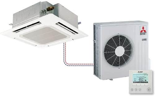
Cassette AC
| Alarm Codes | Solutions |
|---|---|
| P1 | Intake sensor error |
| P2 | Pipe (TH2) sensor error |
| P9 | Pipe (TH5) sensor error |
| E6,E7 | Indoor/outdoor unit communication error |
| P4 | Drain sensor error/Float switch connector (CN4F) open |
| P5 | Drain pump error |
| PA | Forced compressor stop (due to water leakage abnormality) |
| P6 | Freezing/Overheating protection operation |
| EE | Communication error between indoor and outdoor units |
| P8 | Pipe temperature error |
| E4,E5 | Remote controller signal receiving error |
| Fb | Indoor unit control system error (memory error, etc.) |
| PL | Refrigerant circuit abnormal |
| E0,E3 | Remote controller transmission error |
| E1,E2 | Remote controller control board error |
| E9 | Indoor/outdoor unit communication error (Transmitting error) (Outdoor unit) |
| UP | Compressor overcurrent interruption |
| U3,U4 | Open/short of outdoor unit thermistors |
| UF | Compressor overcurrent interruption (When compressor locked) |
| U2 | Abnormal high discharging temperature/49C operated/ insufficient refrigerant |
| U1,Ud | Abnormal high pressure (63H operated)/Overheating protection operation |
| U5 | Abnormal temperature of heat sink |
| U8 | Outdoor unit fan protection stop |
| U6 | Compressor overcurrent interruption/Abnormal of power module |
| U7 | Abnormality of super heat due to low discharge temperature |
| U9,UH | Abnormality such as overvoltage or voltage shortage and abnormal synchronous signal to main circuit/Current sensor error |
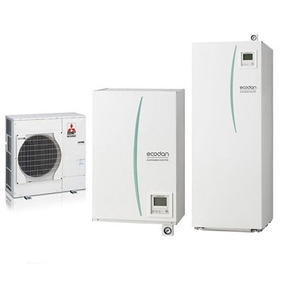
Ecodan
Ecodan air source heat pumps use 1kW of electrical energy input and take 2.2kW of low temperature renewable heat energy from the air, producing a high efficient 3.2kW heat energy output. This heats refrigerant in the system which in turn heats water for domestic hot water and space heating.
| Fault Codes | Problem |
|---|---|
| F3 | Low pressure switch failure — check connection on the board and continuity of switch |
| F5 | High pressure switch failure — check connection onto board and continuity of switch |
| F9 | Both pressure switch contacts are open at the same time — check connection onto board and continuity of switch and for a potential board failure |
| EA | Mis-wiring fault between FTC and Ecodan — check S1,S2,S3 also check voltages and comms |
| EB | Mis-wiring fault between FTC and Ecodan — Check S1,S2,S3 also check voltages and comms |
| EC | Unit cannot finish start up process — generally caused by a comms fault |
| U1 | Ecodan high pressure fault — mainly caused by incorrect water flow rates — check with flow setter |
| U2 | Ecodan high compressor discharge temperature — mainly caused by refrigerant shortage or dirty condenser |
| U3 | Ecodan discharge thermistor problem — mainly caused by TH4 discharge thermistor — open/close circuit |
| U4 | Open or close circuit Ecodan thermistors (TH3, TH32, TH33, TH6, TH7, TH8) — open or close circuit or disconnected from main board |
| U5 | Inverter heat sink overheat protection (W50 and W85 models 77°C, HW140 model 95°C — reduced air flow through Ecodan — faulty fan motor |
| U6 | Inverter/Compressor over current — system indicates possible IPM error |
| U8 | Ecodan fan motor problem — mainly caused by DC fan motor being disconnected, connected or obstructed with the power on or possible main board fault |
| U9 | Over voltage or under voltage — mainly caused by either CN2 or CN5 loose or disconnected or decrease of mains power supply |
| UD | Overheat protection TH3 ≥ 70°C or 63HS ≥ 70°C saturation temperature |
| UF | Compressor over current/Compressor lock — occurs within 30 seconds of compressor start |
| UH | Abnormal running current — < 1A or > 40A detected during operation — check CN5 connections |
| UL | Open circuit (63L ) |
| UP | Over current detected after 30 seconds of operation — do an inverter test to determine outputs balanced |
| E0 | Transmitting Error PAR W21 — check refrigerant address on SW1 of Ecodan |
| E1 | Faulty controller |
| E3 | Transmitting Error (PAR W21) — check refrigerant address on SW1 of Ecodan |
| E4 | Receiving Error (PAR W21) — check refrigerant address of SW1 on Ecodan |
| E5 | Receiving Error (PAR W21) — check refrigerant address of SW1 on Ecodan |
| E6 | Indoor/Outdoor communication error — mainly due to Ecodan being powered up before FTC(2) |
| E8 | Indoor/Outdoor communication error — mainly due to Ecodan being powered up before FTC(2) |
| E9 | Indoor/Outdoor communication error — mainly due to Ecodan being powered up before FTC(2) |
| EF | Non-defined error code — noise interference — power down Ecodan for 30 seconds then switch back on |
| ED | Serial communication fault between Ecodan main board and Ecodan inverter board — mainly due to loose CN2 or CN5 cable |
| P1 | Flow temp sensor fault — TH1 not connected, short or open circuit |
| P6 | Over heating at heat exchanger — lack of water flow, air in the system, flow rate incorrectly set, blockage or pump problem |
| P8 | No temp change at plate heat exchanger — problem with flow rate (too high) — incorrect sizing of system |
| P9 | TH5 Fault — TH5 not connected, short or open circuit, FTC not configured for heating only |
| PE | Inlet water temp fault — TH32 is below 10°C whilst compressor is in operation — possible thermistor out of range, short of gas, incorrect sizing of radiator or problem in the water circuit (blockage, pump failure etc) |
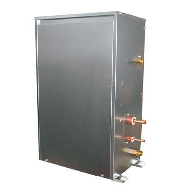
Hot Water Heat Pumps PWFY Series
12.5kW Hot Water Module. Flexibility to create very large systems. Can be installed in conjunction with City Multi VRF air conditioning. Available in one size: PWFY-P100VM-E-BU (12.5kW heating) which is modular to allow creation of larger solutions. Sanitary water heating has suitable applications in: hotels and motels, apartments, commercial kitchens and laundries, office buildings, food processing industry, heat recovery from air conditioning systems into sanitary water storage, and direct sanitary water heating is also possible.
| Fault Codes | Problem |
|---|---|
| 403 | Comms fault between boards — check between control board an inverter board |
| 403 | Comms fault between boards — check between control board an fan board |
| 1102 | High compressor discharge temperature — discharge temp has exceeded 115°C or more — check if short of refrigerant or discharge thermistor |
| 1301 | Low pressure fault — low pressure sensor sensing less than 1 bar immediately before starting |
| 1302 | High pressure fault — check system pressure exceded 32.3 bar, check high pressure sensor (63HS) against gauge pressure |
| 2000 | Pump interlock error — pump interlock open whilst system in operation |
| 2134 | Abnormal water temperature (TH6) has exceded 85°C |
| 2135 | Water source heat exchanger frozen (TH6) or (TH8) reading 2°C |
| 4102 | Open phase fault — check power supply and noise filter for loss of phase, check wiring and fuses |
| 4115 | Power supply abnormal — check power, fuses, connections and PCB |
| 4220 | Low inverter board BUS voltage — less than 200Vdc is detected during in inverter operation — check mains supply |
| 4220 | Bus voltage error PAM damage — replace the inverter board |
| 4220 | High bus voltage Vdc>380v — check power supply and possible faulty inverter board |
| 4220 | Replace inverter board |
| 4230 | High temperature (85°C) on heat sink on inverter — check for blockages in air duct, failure of INV fan failure of INV fan or failure of thermistor (THHS) |
| 4250 | Over current protection — inverter IPM problem or compressor lock — check inverter balance |
| 4250 | ACCT sensor over current detection 34.5A peak or 16A rms is detected — check the compressor for failure, or possible inverter board failure |
| 5102 | Thermistor TH22 failure |
| 5103 | Thermistor TH13 or TH23 failure |
| 5104 | Thermistor TH11 failure |
| 5106 | Thermistor TH6 failure |
| 5108 | Thermistor TH8 failure |
| 5110 | Thermistor THHS failure |
| 5201 | High pressure sensor fault — check the system pressure is >1 bar, check the operation of 63HS high pressure transducer |
| 5202 | Pressure sensor fault |
| 5301 | Current sensor fault, ACCT or DCCT — check inv. error details |
| 5301 | Low output current <1.5A rms whilst the inverter is in operation |
Packaged Hot Water Heat Pump CAHV
45kW Packaged Hot Water Heat Pump. Can be combined to max. 70kW. “Flash-injection Circuit”, which is designed for our ZUBADAN CITY MULTI (air conditioning system for cold regions), is mounted in our new Hot Water Heat Pump. By utilizing our advanced “Flash-injection Circuit” and the latest high-efficiency compressor, Hot Water Heat Pump provides hot water upto 70°C, and produces less capacity drop at low outdoor temperature.
| Error Codes | Problem |
|---|---|
| AFSA | Water supply cut-off (flow switch has been triggered) — check flow switch and wiring |
| AHP1 | High pressure fault — check water flow, possible high pressure sensor fault LEV fault |
| AdSH | Compressor crank case temperature of 10°C or less for 40 minutes while compressor in operation — check for possible failure of fan motor, low pressure sensor, compressor shell thermistor, high pressure sensor, discharge thermistor (TH1 TH5), LEV or SV2 |
| 1303 | Low pressure protection low pressure below 6 bar within 30 sec of start up — possible failure of LP sensor, air inlet thermistor fault (TH4 TH8), suction temperature (TH2 TH6), LEV bypass check valve |
| 1103 | Compressor shell bottom temperature exceeded 80°C detected whilst compressor running |
| 5109 | Compressor shell thermistor faulty (TH3 TH6), LEV failure |
| 5110 | Outside temperature thermistor fault — check TH9 |
| 5112 | Water inlet temperature — check TH10 main circuit |
| 5111 | Water inlet temperature — check TH12 sub circuit |
| 5113 | Outlet water temperature — check TH11 main circuit |
| 5103 | Outlet water temperature — check TH12 sub circuit |
| 5107 | Compressor shell temperature — check TH3 main circuit |
| 5101 | Compressor shell temperature — check TH7 sub circuit |
| 5105 | Discharge temperature — check TH1 main circuit |
| 5102 | Discharge temperature — check TH5 sub circuit |
| 5106 | Inlet temperature — check TH2 main circuit |
| 5104 | Inlet temperature — check TH6 sub circuit |
| 5108 | Air to refrigerant heat exchanger inlet temperature — check TH4 main circuit |
| 5114 | Air to refrigerant heat exchanger inlet temperature — check TH8 sub circuit |
| 5115 | Common return water when using multiple outdoors — check TH14 |
| 5117 | Common return water when using multiple outdoors — check TH15 |
| 5118 | High pressure sensor or high pressure fault — check 63HS sensor or 63H (hp switch) |
| 7113 | Low pressure sensor low or low pressure fault — check 63LS |
| 7117 | Model setting error 1 — mis-set switch |
| 4115 | Model setting error 2 — faulty Z21 resistor |
| A471 | Power supply frequency fault — power supply frequency is not 50Hz or 60Hz |
| 1104 | Discharge temperature fault — 120°C detected during compressor operation — check water flow, pump, high pressure sensor fault or LEV fault |
| AC61 | Power supply fault — check transmission power supply or if PCB faulty |
MR Slim Operation Light Blinking
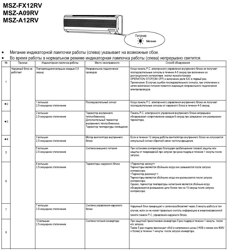
Flashing of POWER lamp indicates abnormalities. Before taking measures, make sure that the symptom reappears for accurate troubleshooting. Self check table
When the indoor unit has started operation and the above detection method has detected an abnormality (the first detection after the power ON), the indoor electronic control P.C. board turns OFF the indoor fan motor with OPERATION INDICATOR lamp flashing.
| Indicator lamp | Solution |
|---|---|
| POWER lamp flashes. 0.5-second ON | Mis-Wiring or serial signal. Outdoor unit does not operate. When the serial signal form the outdoor unit is not received for a maximum of 6 minutes. |
| POWER lamp lights up | Out door control system. Outdoor unit does not operate. When it cannot properly read data in the nonvolatile memory of the inverter P.C. board or the outdoor electronic control P.C. board. Check the blinking pattern of the LED on the inverter P.C. board or the outdoor lectronic control P.C. board. |
| POWER lamp flashes. 2-time flash | Indoor coil thermistor. Room temperature thermistor. Indoor unit and outdoor unit do not operate. When the indoor coil or the room temperature thermistor is short or open circuit. |
| POWER lamp flashes. 3-time flash | Indoor fan motor. Indoor unit and outdoor unit do not operate. When the rotational frequency feedback signal is not emit during the indoor fan operation. |
| POWER lamp flashes. 5-time flash | Out door power system. Indoor unit and outdoor unit do not operate. When it consecutively occurs 3 times that the compressor stops for overcurrent protection or start-up failure protection witth in 1 minute after start-up. |
| POWER lamp flashes. 6-time flash | Outdoor thermistors. Indoor unit and outdoor unit do not operate. When the outdoor thermistors short or open circuit during the compressor operation. |
| POWER lamp flashes. 7-time flash | Out door control system. Indoor unit and outdoor unit do not operate. When it cannot properly read data in the nonvolatile memory of the inverter P.C. board or the outdoor electronic control P.C. board. |
| POWER lamp flashes. 14-time flash | Other abnonmality. Indoor unit and outdoor unit do not operate. An abnormality other than above mentioned is deteced. Confirm the abnormarity in detail using the failure mode recall function. |
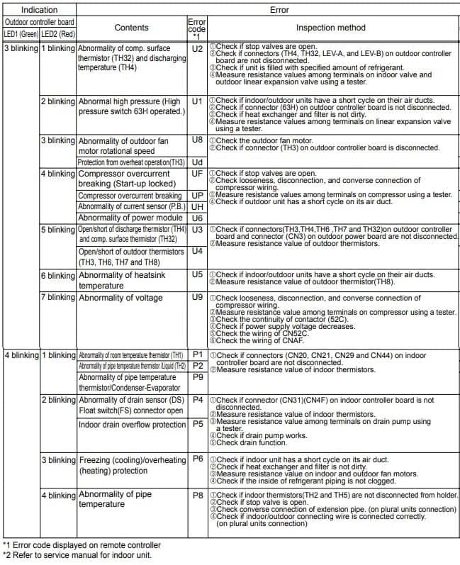
Split AC Timer Light Blinking
| Trouble | Contents |
|---|---|
| 3 blinking-1 blinking | Abnormality of comp. surface thermistor (TH32) and discharging temperature (TH4) |
| 3 blinking-2 blinking | Abnormal high pressure (High pressure switch 63H operated.) |
| 3 blinking-3 blinking | Abnormality of outdoor fan motor rotational speed. Protection from overheat operation(TH3). |
| 3 blinking-4 blinking | Compressor overcurrent breaking (Start-up locked). Compressor overcurrent breaking. Abnormality of current sensor (P.B.). Abnormality of power module. |
| 3 blinking-5 blinking | Open/short of discharge thermistor (TH4) and comp. surface thermistor (TH32). Open/short of outdoor thermistors (TH3, TH6, TH7 and TH8). |
| 3 blinking-6 blinking | Abnormality of heatsink temperature |
| 3 blinking-7 blinking | Abnormality of voltage |
| 4 blinking-1 blinking | Abnormality of room temperature thermistor (TH1). Abnormality of pipe temperature thermistor /Liquid (TH2). Abnormality of pipe temperature thermistor/Condenser-Evaporator. |
| 4 blinking-2 blinking | Abnormality of drain sensor (DS) Float switch(FS) connector open. Indoor drain overflow protection. |
| 4 blinking-3 blinking | Freezing (cooling)/overheating (heating) protection |
| 4 blinking-4 blinking | Abnormality of pipe temperature |
Aircon RedLINK Codes
| Error Codes | Meaning |
|---|---|
| E0 27 | Verify device temperature is within operating range. If within range for at least 30 minutes and problem persists, replace Remote Controller. |
| E0 91 | Communication was established between wireless receiver and the indoor unit, but communication has been lost for 10 minutes. Check cable connection. Try replacing the cable. |
| E1 29 | Attempting to connect incompatible wireless devices. |
| E1 34 | Low signal strength. Move wireless device to a different location and try again. |
| E1 38 | Make sure Connect light on wireless receiver is flashing and you are 2+ feet away from wireless receiver. |
| E1 54 | Indoor unit does not support wireless receiver. |
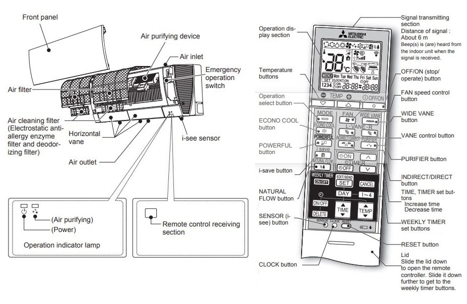
Troubleshooting
Even if these items are checked, when the unit does not recover from the trouble, stop using the air conditioner and consult your dealer.
Symptom: The unit cannot be operated.
Explanation & Check points:
- Is the breaker turned on?
- Is the power supply plug connected?
- Is the ON timer set?
Symptom: The horizontal vane does not move.
Explanation & Check points:
- Are the horizontal vane and the vertical vane installed correctly?
- Is the fan guard deformed?
- When the breaker is turned on, the horizontal vanes’ position will be reset in about a minute. After the reset has completed, the normal horizontal vanes’ operation resumes. The same is true in the emergency cooling operation.
Symptom: The airfl ow direction changes during operation. The direction of the horizontal vane cannot be adjusted with the remote controller.
Explanation & Check points:
- When the unit is operated in COOL or DRY mode, if the operation continues with air blowing down for 0.5 to 1 hour, the direction of the airfl ow is automatically set to horizontal position to prevent water from condensing and dripping.
- In the heating operation, if the airfl ow temperature is too low or when defrosting is being done, the horizontal vane is automatically set to horizontal position.
Symptom: Water leaks from the outdoor unit.
Explanation & Check points:
- During COOL and DRY operations, pipe or pipe connecting sections are cooled and this causes water to condense.
- In the heating operation, water condensed on the heat exchanger drips down.
- In the heating operation, the defrosting operation makes ice forming on the outdoor unit melt and drip down.
Symptom: The display on the remote controller does not appear or it is dim. The indoor unit does not respond to the remote control signal.
Explanation & Check points:
- Are the batteries exhausted?
- Is the polarity (+, -) of the batteries correct?
- Are any buttons on the remote controller of other electric appliances being pressed?
Symptom: The room cannot be cooled or heated sufficiently.
Explanation & Check points:
- Is the temperature setting appropriate?
- Is the fan setting appropriate? Please change fan speed to High or Super High.
- Are the fi lters clean?
- Is the fan or heat exchanger of the indoor unit clean?
- Are there any obstacles blocking the air inlet or outlet of the indoor or outdoor unit?
- Is a window or door open?
- It may take a certain time to reach the setting temperature or may not reach that dependingon the size of the room, the ambient temperature, and the like.
Symptom: The air from the indoor unit smells strange.
Explanation & Check points:
- Are the fi lters clean?
- Is the fan or heat exchanger of the indoor unit clean?
- The unit may suck in an odor adhering to the wall, carpet, furniture, cloth, etc. and blow it out with the air.
Symptom: Weekly timer does not operate according to settings.
Explanation & Check points:
- Is the ON/OFF timer set?
- Transmit the setting information of the weekly timer to the indoor unit again. When the information is successfully received, a long beep will sound from the indoor unit. If information fails to be received, 3 short beeps will be heard. Ensure information is successfully received.
- When a power failure occurs and the main power turns off, the indoor unit built-in clock will be incorrect. As a result, the weekly timer may not work normally.
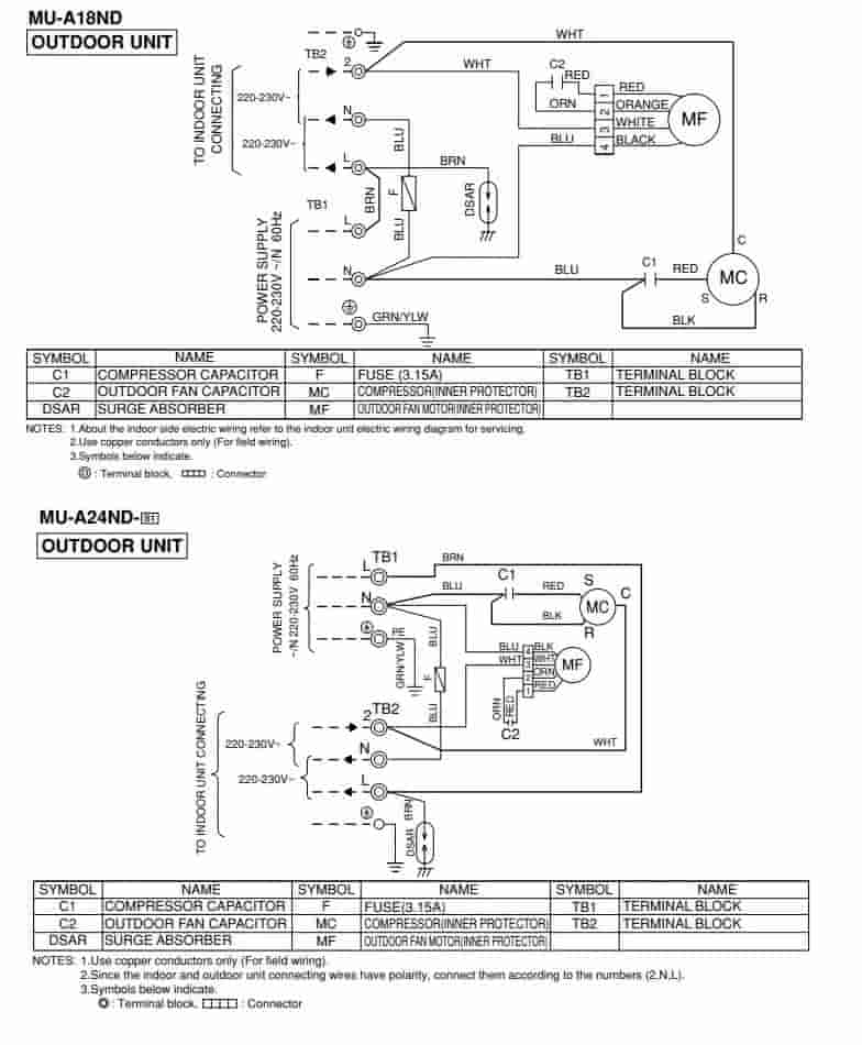
Electrical Wiring Diagram
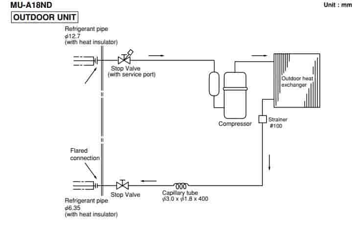
Refrigerator Diagram
Manuals PDF
Mitsubishi Air Conditioning Service Handbook PDF
Mitsubishi Air Conditioning Service Manual PDF
Mitsubishi Electric MRCH1 Remote ControllerOperating Manual PDF
Mitsubishi Electric Split AC Manual MSZ-AP22VGD PDF
Mhk1 Wireless Remote Receiver Kit Manual PDF
MIFH1, MRCH1, MCCH1, MOS1 Controller Kit Installation Manual PDF
Mitsubishi Air Conditioning Error Codes PDF – R410A Systems
- Author
- Recent Posts
Regarding error and fault codes, we believe sharing knowledge is the best way to help everyone. That is why we established ACErrorCode.com, to give you every bit of info you need as a customer. HVAC Expert Contact: dannyreese@acerrorcode.com
*If you can’t find the code you’re looking for on our site, please let us know, and we’ll update our database as soon as possible.
Обновлено: 02.06.2023
Довольно распространенная ошибка Mitsubishi L200 u1102 ставит в тупик водителей этого пикапа. Расшифровка должна сигнализировать о проблемах с автоматической коробкой передач. Интересно, что код также появляется на L200, оснащенном механической коробкой передач.
Ошибки u1102 и u1101
Специалисты рекомендуют проанализировать причины появления отклонений. Например, если они отображаются после выполнения каких-либо работ с автомобилем. Бывает, что ошибки возникают из-за помех в электропроводке. Хозяин установил сигнализацию и код неисправности начал мигать.
Одним словом, в большинстве случаев на Mitsubishi L200 ошибка u1102 и аналогичный u1101 ничего страшного не грозят. Обычно сканер некорректно отображает информацию, показывая работу системы, которой, в общем-то, может не быть на автомобиле. Также возможно, что программа начнет отображать ошибку после обновления или перепрошивки.
Совет 1. Перезагрузите свой мозг и дважды проверьте. Как правило, если все в порядке, ошибка больше не отображается. Сброс осуществляется отсоединением клеммы аккумулятора. Рекомендуется периодически выполнять эту операцию для очистки памяти CU от ложных кодов ошибок. Очень важно перенастроить бортовой компьютер в соответствии с вашим стилем вождения.
Совет 3: проверьте работающую сеть контроллера или CAN-шину. Возможный обрыв цепи и другие проблемы с цепью.
Однако прямую ошибку u1102 от Mitsubishi L200 игнорировать точно не стоит. Вероятно, действительно есть заминка. При поиске неисправности необходимо ее собственно выявить, также проверить. Одному человеку еще рано полагаться целиком на электронику, по крайней мере, для заботливого автомобилиста.
Так что, если вы получили ошибку, указывающую на проблемы с АКПП, стоит поставить галочку в квадрате старым испытанным способом.
просто вставьте щуп, чтобы определить высоту от ГОРЯЧЕГО до ОХЛАЖДЕНИЯ, нормальной толщины (масло не должно стекать, как вода), цвета. Красный или темно-красный оттенок считается идеальным для трансмиссионной жидкости. В масле не должно быть металлической пыли, стружки, посторонних предметов. Запах технический, без запаха подгоревшей или тухлой рыбы.
На этом проверка не закончилась. Также необходимо провести экспериментальный тест-драйв коробки на предмет ошибок.
- Нажмите педаль тормоза в нейтральном режиме.
- Переключите фазы АКПП на все фазы, обеспечив интервал в 4 секунды. Перевод должен быть получен немедленно, без промедления.
Внимание. Все источники шума при управлении машиной в режиме ХХ должны быть выключены (радио, радио). Необходимо внимательно прислушаться, чтобы определить, нормально ли включены передачи. Селектор можно вернуть в исходное положение с нажатым тормозом, но без паузы. Опять же переключатели должны быть острыми.
Не двигая автомобиль, автоматическая коробка передач должна работать бесшумно, без толчков, толчков и посторонних шумов. Допускаются легкие и мягкие колебания, но они не должны быть продолжительными или прерывистыми.
К тому же АКПП L200 управляется на лету, в динамике. Желательно выбирать ровный участок дороги, чтобы не было препятствий для набора скорости 100 км / ч. Нормальная работа коробки должна подтверждаться: плавным троганием с места и разгоном, быстрым торможением и разгоном с места, свободным движением с понижением передачи и т.д.
И вам также придется иметь дело с другими ошибками. Расшифруйте их и приступайте к проверке некоторых узлов и систем автомобиля.
Диагностика электроникой и вручную: таблица кодов неисправностей
ЭБУ или блок управления современного L200 имеет встроенную систему самодиагностики. Постоянно контролирует состояние двигателя, коробки передач и других компонентов автомобиля и в случае обнаружения выявляет и отображает ошибку в виде значка на цифровом дисплее.
Диагностический код определяется с помощью сканера, подключенного к разъему замка. В памяти ЭБУ хранятся не только ранее отображаемые диагностические ошибки, но и стандартные коды, введенные производителем.
Считывание кодов с помощью электроники имеет другое название — компьютерная диагностика. Включает в себя не только считывание сигналов с датчиков, но и стирание кодов, их последующую коррекцию и т.д.
Дилерские сканеры и другие системы могут использоваться в качестве инструментов. Портативные считыватели, многофункциональные опоры, OEM, OBDII, MUTIII — все это оборудование способно находить общий язык с кодами, диагностировать неисправности, считывать и обнаруживать малейшие ошибки в работе автомобильных компонентов и подсистем.
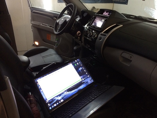
Бывает, что сканеры не могут связаться с аппаратом. Не нужно паниковать. Рекомендуется проверить состояние диагностического разъема и контактов. При использовании датчика возможно, что контакты окислены или утоплены в разъеме.
Компьютерная диагностика проводится в режиме регулярного обслуживания автомобиля (не реже одного раза в год) или после того, как водитель обнаружит ошибочные и сбои в работе автомобиля, когда загорятся значки ошибок и т.д.
Выше было сказано, что на L200 последних лет выпуска сканер с программным обеспечением подключается в стандартной комплектации. Он загружает все коды, передаваемые датчиками, и передает их на табло.
вы можете прочитать ошибки вручную. Так проводилась диагностика на старых моделях, не имевших электроники. Такие коды обычно называют Flash.
Перед началом процедуры чтения мы проверили:
- чтобы аккумулятор не разряжался (уровень заряда выше 11 В);
- дроссельная заслонка была полностью закрыта;
- рычаг управления АКПП находился в P / N (на МКПП — нейтраль);
- отключены все потребители электроэнергии;
- моторный агрегат нагревается до рабочих значений.
Блок диагностического разъема
Мгновенный замер производился следующим образом.
Надежность или неисправность систем автомобиля определяли по миганию индикатора.
- Если все нормально, ошибок нет: индикатор включается и гаснет с интервалом 0,25 сек.
- В противном случае индикатор мигает каждые 0,5 секунды.
Специалисты умели читать основные моменты индикаторов, выводить из них последовательность и создавать код. Например, первое число диагностической пиктограммы выражалось начальными вспышками, а после короткой паузы отображалась следующая строка миганий индикатора и определялось второе число.
Расшифровка ошибок проводится по готовой таблице. Под названием Flash — коды, полученные вручную через диагностический разъем. SAE — пиктограммы, отображаемые электронными сканерами.
L200 Mitsubishi ошибка u1102
Довольно распространённая u1102 ошибка Mitsubishi L200 озадачивает водителей этого пикапа не на шутку. По расшифровке она должна сигнализировать о проблемах с АКПП. Интересно, что высвечивается код и на Л200, оснащённых механической коробкой передач.
Ошибки u1102 и u1101
Эксперты рекомендуют анализировать причины появления отклонений. К примеру, если они показываются после проведения каких-либо работ с автомобилем. Бывает, что ошибки возникают из-за вмешательства в электропроводку. Владелец установил сигнализацию, и стал высвечиваться код неисправности.
Сканер MUTIII
Одним словом, в большинстве случаях на Mitsubishi L200 ошибка u1102 и ей подобная u1101 ничем страшным не грозит. Обыкновенно, неправильно отображает информацию сканер, показывающий работу системы, которой, вообще, может не быть на автомобиле. Возможно также, что программа начинает видеть ошибку после обновления или перепрошивки.
Совет 1: обнулить мозги и перепроверить. Как правило, если всё в порядке, ошибка снова не высветится. Обнуление проводится методом скидывания клеммы аккумулятора. Это рекомендуется делать периодически, чтобы стирать из памяти БУ ложные коды ошибок. Обязательно проведение повторной настройки бортового компьютера по собственному стилю езды.
Совет 3: проверить рабочую сеть контроллёров или CAN-шину. Возможен обрыв и другие проблемы цепи.
Однако игнорировать прямую ошибку u1102 Mitsubishi L200, безусловно, не стоит. Вполне вероятно, что закавыка действительно есть. При поиске любой неисправности надо по-настоящему выявлять её, добавочно проверять. Надеяться целиком на электронику человеку, по крайней мере, заботливому автолюбителю, пока рано.
Итак, если выведена ошибка, указывающая на проблемы с АКПП, стоит проверить коробку старым проверенным способом.
Достаточно вдеть щуп, чтобы определить высоту от HOT до COOL, нормальную густоту (масло не должно стекать как вода), цвет. Красный или тёмно-красный оттенок считается идеальным для рабочей трансмиссионной жидкости. В масле не должно быть металлической пыли, стружки, посторонних взвесей. Запах – характерно технический, без обоняния гари или протухшей рыбы.
Проверка на этом не закончена. Надо ещё провести экспериментальный тест-драйв коробки на ошибки.
Внимание. Все источники шума при проверке автомата в режиме ХХ должны быть отключены (магнитола, радио). Надо хорошо слышать, чтобы определить, нормально ли включаются передачи. Селектор можно прогнать по скоростям ещё раз при выжатом тормозе, но уже без пауз. Опять же, переключения должны быть чёткими.
Без движения автомобиля АКПП обязана работать тихо, без толчков, пинков и посторонних звуков. Лёгкие и плавные вибрации допускаются, но они не должны иметь затяжной или прерывистый характер.
Далее, АКПП L200 проверяется на ходу, в динамике. Желательно выбрать ровный участок дороги, чтобы не было препятствий для набора скорости в 100 км/ч. О нормальной работе коробки должны свидетельствовать: плавный старт и разгон, быстрое торможение и ускорение с места, свободное движение с понижением передач и т. д.
И также надо поступать с другими ошибками. Расшифровывать их, и начинать проверку определённых узлов и систем автомобиля.
Диагностика электроникой и вручную: таблица кодов неисправностей
Компьютерная диагностика проводится с целью выявления неисправностей
ЭБУ или блок управления современных L200 имеет встроенную систему самодиагностики. Она непрерывно отслеживает состояние мотора, коробки и других узлов автомобиля, и в случае обнаружения, идентифицирует и выводит ошибку в виде пиктограммы на цифровое табло.
Диагностический код определяется с помощью сканера, подключённого к разъёму блока. В памяти ЭБУ хранятся не только высвечиваемые ранее диагностические ошибки, но и стандартные коды, введённые производителем.
Считывание кодов электроникой имеет и другое название – компьютерная диагностика. Она включает в себя не только чтение сигналов от датчиков, но и стирание кодов, последующую их коррекцию и т. д.
В качестве приборов могут использоваться дилерские сканеры и другие системы. Портативные ридеры, мультифункциональные стенды, ОЕМ, OBDII, MUTIII – всё это оборудование умеет находить общий язык с кодами, диагностировать неисправности, считывать и засекать малейшие ошибки в работе автомобильных узлов и подсистем.
Бывает, что сканеры не могут связаться с машиной. Тут не нужно паниковать. Рекомендуется проверить состояние диагностического разъёма и контактов. Не исключено, если пикап подержанный, что пины окислены или утоплены в разъёме.
Компьютерная диагностика проводится либо в режиме регулярного обслуживания автомобиля (не реже одного раз в год), либо после того, как водитель замечает некорректность и ошибки в работе машины, при загорании пиктограмм неисправностей и т. п.
Выше было сказано, что на Л200 последних годов выпуска сканер с ПО подключен штатно. Он скачивает все коды, транслируемые датчиками, и передаёт на табло.
Есть возможность считывать неисправности вручную. Именно так проводилась диагностика на старых моделях, на которых не было электроники. Такие коды принято называть Flash.
Перед тем как начинали процедуру считывания, проверяли:
- чтобы аккумулятор не был разряжён (уровень заряда выше 11 V);
- дроссельная заслонка была полностью закрыта;
- рычаг управления АКПП стоял в P/N (на МКПП – нейтральное положение);
- все потребители электричества были отключены;
- моторная установка прогрета до рабочих значений.
Считывание Flash проводилось так.
Безотказность или неисправность систем автомобиля определялась по миганию индикатора.
- Если всё нормально, ошибок нет – индикатор загорается и гаснет с интервалом 0,25 сек.
- В противном случае – индикатор моргает каждые 0,5 сек.
Специалисты умели читать высвечивания индикаторов, выводить по ним последовательность и создавать код. Например, первое число диагностической пиктограммы выражалось по начальным миганиям, а после короткой паузы выводился следующий ряд индикаторных мерцаний, и определялось второе число.
Расшифровка ошибок проводится по готовой таблице. Под наименованием Flash – коды, полученные через диагностический разъём вручную. SAE – пиктограммы, выведенные электронными сканерами.
| Flash | SAE | Расшифровка |
|---|---|---|
| 31 | Р0105 | Датчик абсолютного давления во впускном коллекторе |
| 43 | Р0110 | Датчик температуры воздуха на впуске |
| 42 | Р0115 | Датчик температуры охлаждающей жидкости |
| 41 | Р0120 | Датчик положения дроссельной заслонки |
| 21 | Р0130 | Передний кислородный датчик |
| 22 | Р0136 | Задний кислородный датчик |
| 25 | Р0171 | Сигнал бедной смеси |
| 26 | Р0172 | Сигнал богатой смеси |
| 16 | Р0351/0352/0353/0354 | Пропуск воспламенения в цилиндрах |
| 27 | Р0420 | Низкая эффективность каталитического нейтрализатора |
| 88 | U1002 | CAN шина |
Сегодня самостоятельная диагностика подразумевает использование сканеров-адаптеров, наподобие OBDII. Они позволяют интегрировать с блоком управления автомобилем не только ноутбук, но и другие современные гаджеты, в том числе и мобильные устройства.
Во многих случаях появление на Митсубиси L200 ошибки u1102, это лишний повод провести общий технический осмотр, в ходе которого обновляется топливный фильтр, промываются форсунки, заменяются свечи, снимается и чистится ДМРВ.
Довольно распространенная ошибка Mitsubishi L200 u1102 ставит в тупик водителей этого пикапа. Расшифровка должна сигнализировать о проблемах с автоматической коробкой передач. Интересно, что код также появляется на L200, оснащенном механической коробкой передач.
L200 Mitsubishi ошибка u1102
Ошибки u1102 и u1101
Специалисты рекомендуют проанализировать причины появления отклонений. Например, если они отображаются после выполнения каких-либо работ с автомобилем. Бывает, что ошибки возникают из-за помех в электропроводке. Хозяин установил сигнализацию и код неисправности начал мигать.
Сканер MUTIII
Одним словом, в большинстве случаев на Mitsubishi L200 ошибка u1102 и аналогичный u1101 ничего страшного не грозят. Обычно сканер некорректно отображает информацию, показывая работу системы, которой, в общем-то, может не быть на автомобиле. Также возможно, что программа начнет отображать ошибку после обновления или перепрошивки.
Совет 1. Перезагрузите свой мозг и дважды проверьте. Как правило, если все в порядке, ошибка больше не отображается. Сброс осуществляется отсоединением клеммы аккумулятора. Рекомендуется периодически выполнять эту операцию для очистки памяти CU от ложных кодов ошибок. Очень важно перенастроить бортовой компьютер в соответствии с вашим стилем вождения.
Совет 3: проверьте работающую сеть контроллера или CAN-шину. Возможный обрыв цепи и другие проблемы с цепью.
Однако прямую ошибку u1102 от Mitsubishi L200 игнорировать точно не стоит. Вероятно, действительно есть заминка. При поиске неисправности необходимо ее собственно выявить, также проверить. Одному человеку еще рано полагаться целиком на электронику, по крайней мере, для заботливого автомобилиста.
Так что, если вы получили ошибку, указывающую на проблемы с АКПП, стоит поставить галочку в квадрате старым испытанным способом.
просто вставьте щуп, чтобы определить высоту от ГОРЯЧЕГО до ОХЛАЖДЕНИЯ, нормальной толщины (масло не должно стекать, как вода), цвета. Красный или темно-красный оттенок считается идеальным для трансмиссионной жидкости. В масле не должно быть металлической пыли, стружки, посторонних предметов. Запах технический, без запаха подгоревшей или тухлой рыбы.
На этом проверка не закончилась. Также необходимо провести экспериментальный тест-драйв коробки на предмет ошибок.
- Нажмите педаль тормоза в нейтральном режиме.
- Переключите фазы АКПП на все фазы, обеспечив интервал в 4 секунды. Перевод должен быть получен немедленно, без промедления.
Внимание. Все источники шума при управлении машиной в режиме ХХ должны быть выключены (радио, радио). Необходимо внимательно прислушаться, чтобы определить, нормально ли включены передачи. Селектор можно вернуть в исходное положение с нажатым тормозом, но без паузы. Опять же переключатели должны быть острыми.
Не двигая автомобиль, автоматическая коробка передач должна работать бесшумно, без толчков, толчков и посторонних шумов. Допускаются легкие и мягкие колебания, но они не должны быть продолжительными или прерывистыми.
К тому же АКПП L200 управляется на лету, в динамике. Желательно выбирать ровный участок дороги, чтобы не было препятствий для набора скорости 100 км / ч. Нормальная работа коробки должна подтверждаться: плавным троганием с места и разгоном, быстрым торможением и разгоном с места, свободным движением с понижением передачи и т.д.
И вам также придется иметь дело с другими ошибками. Расшифруйте их и приступайте к проверке некоторых узлов и систем автомобиля.
Диагностика электроникой и вручную: таблица кодов неисправностей
Компьютерная диагностика проводится для выявления неисправностей
ЭБУ или блок управления современного L200 имеет встроенную систему самодиагностики. Постоянно контролирует состояние двигателя, коробки передач и других компонентов автомобиля и в случае обнаружения выявляет и отображает ошибку в виде значка на цифровом дисплее.
Диагностический код определяется с помощью сканера, подключенного к разъему замка. В памяти ЭБУ хранятся не только ранее отображаемые диагностические ошибки, но и стандартные коды, введенные производителем.
Считывание кодов с помощью электроники имеет другое название — компьютерная диагностика. Включает в себя не только считывание сигналов с датчиков, но и стирание кодов, их последующую коррекцию и т.д.
Дилерские сканеры и другие системы могут использоваться в качестве инструментов. Портативные считыватели, многофункциональные опоры, OEM, OBDII, MUTIII — все это оборудование способно находить общий язык с кодами, диагностировать неисправности, считывать и обнаруживать малейшие ошибки в работе автомобильных компонентов и подсистем.
Бывает, что сканеры не могут связаться с аппаратом. Не нужно паниковать. Рекомендуется проверить состояние диагностического разъема и контактов. При использовании датчика возможно, что контакты окислены или утоплены в разъеме.
Компьютерная диагностика проводится в режиме регулярного обслуживания автомобиля (не реже одного раза в год) или после того, как водитель обнаружит ошибочные и сбои в работе автомобиля, когда загорятся значки ошибок и т.д.
Выше было сказано, что на L200 последних лет выпуска сканер с программным обеспечением подключается в стандартной комплектации. Он загружает все коды, передаваемые датчиками, и передает их на табло.
вы можете прочитать ошибки вручную. Так проводилась диагностика на старых моделях, не имевших электроники. Такие коды обычно называют Flash.
Перед началом процедуры чтения мы проверили:
- чтобы аккумулятор не разряжался (уровень заряда выше 11 В);
- дроссельная заслонка была полностью закрыта;
- рычаг управления АКПП находился в P / N (на МКПП — нейтраль);
- отключены все потребители электроэнергии;
- моторный агрегат нагревается до рабочих значений.
Блок диагностического разъема
Мгновенный замер производился следующим образом.
Надежность или неисправность систем автомобиля определяли по миганию индикатора.
- Если все нормально, ошибок нет: индикатор включается и гаснет с интервалом 0,25 сек.
- В противном случае индикатор мигает каждые 0,5 секунды.
Специалисты умели читать основные моменты индикаторов, выводить из них последовательность и создавать код. Например, первое число диагностической пиктограммы выражалось начальными вспышками, а после короткой паузы отображалась следующая строка миганий индикатора и определялось второе число.
Расшифровка ошибок проводится по готовой таблице. Под названием Flash — коды, полученные вручную через диагностический разъем. SAE — пиктограммы, отображаемые электронными сканерами.
| Стремительный | SAE | Расшифровка |
|---|---|---|
| 31 год | P0105 | Датчик абсолютного давления в коллекторе |
| 43 год | P0110 | Датчик температуры всасываемого воздуха |
| 42 | P0115 | Датчик температуры охлаждающей жидкости |
| 41 год | P0120 | Датчик положения дроссельной заслонки |
| 21 год | P0130 | Передний кислородный датчик |
| 22 | P0136 | Датчик кислорода задний |
| 25 | P0171 | Бедный сигнал |
| 26 год | P0172 | Сигнализация богатой смеси |
| 16 | P0351 / 0352/0353/0354 | Пропущенное зажигание в цилиндрах |
| 27 | P0420 | Низкая эффективность каталитического нейтрализатора |
| 88 | U1002 | CAN-шина |
Сегодня самодиагностика предполагает использование адаптеров сканера, например, OBDII. Они позволяют интегрировать с блоком управления автомобилем не только ноутбук, но и другие современные гаджеты, в том числе мобильные устройства.
Во многих случаях появление ошибки u1102 на Mitsubishi L200 является еще одним поводом для проведения общего технического осмотра, в ходе которого обновляется топливный фильтр, промываются форсунки, заменяются свечи зажигания, снимается датчик расхода d массового воздуха и почистил.
Читайте также:
- Ошибка термостата шевроле орландо
- Тойота витц схема зарядки
- Как проверить гидромуфту на камазе
- Передняя подвеска ваз 2104 схема с описанием
- Как проверить стартер ауди 80

