
- Коды ошибок спецтехники JCB
- Коды ошибок двигателя JCB (Isuzu 4HK, 6HK)
- Истории из практики ремонта JCB
При возникновении неисправности на технике, информационный дисплей EMS сразу отображает на экране ошибки, при этом зуммер (сигнализатор) начинает пищать. Для отключения зуммера нужно нажать на кнопку ACK на мониторе JCB.
Подробное описание ошибок электронных блоков управления гидравлики ECU1 728/29900 728/35700 728/29900 728/35700 и блока электроники ECUW 728/35800 728/18500 728/15500 JCB.
Коды ошибок JCB (гидравлики и электроники)

| Коды ошибок |
Надпись на дисплее монитора | Описание неисправности |
| 101 | CRANK | ЭБУ1 не обнаруживает сигнал от коленвала. |
| 102 | FUEL | Цепь датчика топлива разомкнута |
| 103 | EN TMP | Цепь датчика температуры двигателя разомкнута. |
| 104 | HYD TMP | Цепь датчика температуры гидравлической жидкости разомкнута. |
| 105 | SET PT | Цепь потенциометра заданного положения дроссельной заслонки разомкнута. |
| 106 | SENS PT | Цепь потенциометра фактического положения дроссельной заслонки разомкнута. |
| 107 | OIL SW | Датчик давления масла выдает сигнал наличия давления при отключенном двигателе. |
| 108 | FLYWHEEL | Датчик карданной передачи выдает сигнал оборотов двигателя при отключенном |
| 109 | ALT | Генератор выдает сигнал наличия напряжения при отключенном двигателе. |
| 110 | THR SOL | Цепь электромагнитного клапана дроссельной заслонки разомкнута. Обнаруживается только при отключенном двигателе. |
| 111 | BOOM SP | Цепь регулирования малой скорости стрелы разомкнута. |
| 113 | MAX FLW | Цепь электромагнитного клапана максимального расхода разомкнута. Для машин JS200W данная ошибка может быть обнаружена тольк |
| 115 | BOOM | Цепь электромагнитного клапана приоритета разомкнута |
| 116 | FL PMP | Цепь выходного контура насоса дозаправки разомкнута. |
| 117 | HORN | Цепь выходного контура клаксона разомкнута. |
| 118 | HYD PMP | Цепь гидравлического насоса разомкнута. Поскольку клапан является пропорциональным, ошибка обнаруживается только при отключенном двигателе |
| 119 | SLW LCK | Цепь электромагнитного клапана блокиратора стрелы разомкнута. |
| 120 | HYD FAN | Цепь выходного контура вентилятора гидросистемы разомкнута. Обнаруживается только при отключенном двигателе |
| 121 | SLW BRK | Цепь электромагнитного клапана разблокировки стрелы разомкнута |
| 122 | SLW ST | Цепь электромагнитного клапана отключения стрелы разомкнута. |
| 127 | TL CHNG | Цепь электромагнитного клапана переключения скорости движения разомкнута. |
| 128 | WASHER | Цепь двигателя омывателя разомкнута. |
| 129 | DOZER | Цепь электромагнитного клапана отвала разомкнута. |
| 130 | GRB CW | Цепь электромагнитного клапана вращения грейфера по часовой стрелке разомкнута. |
| 131 | GRB CCW | Цепь электромагнитного клапана вращения грейфера против часовой стрелки разомкнута. |
| 132 | LW FLOW | Цепь электромагнитного клапана низкого расхода разомкнута. |
| 133 | ISOL | Цепь электромагнитного клапана гидроизолятора разомкнута. |
| 135 | 2 STAGE | Цепь предохранительного электромагнитного клапана ступени 2 разомкнута. |
| 136 | QK HTCH | Цепь электромагнитного клапана быстрой сцепки разомкнута. |
| 138 | HAMMER | Цепь электромагнитного клапана молота разомкнута. |
| 139 | CUSHION | Цепь электромагнитного клапана твердой/мягкой подушки разомкнута. |
| 142 | ENG SD | Цепь выходного контура отключения двигателя разомкнута. |
| 143 | GLW PLG | Цепь выходного контура свечей накаливания разомкнута. |
| 156 | TL FLW3 | Цепь электромагнитного клапана расхода 3 движения разомкнута. |
| 157 | TL FLW2 | Цепь электромагнитного клапана расхода 2 движения разомкнута. |
| 158 | GR CHNG | Цепь электромагнитного клапана М2 или переключения передач разомкнута. |
| 159 | BRKE LT | Цепь выходного контура лампы тормоза разомкнута. |
| 160 | AXLE LK | Цепь электромагнитного клапана блокировки моста разомкнута. |
| 161 | STAB UP | Цепь электромагнитного клапана подъема стабилизатора разомкнута. |
| 162 | STAB DIN | Цепь электромагнитного клапана опускания стабилизатора разомкнута. |
| 163 | STAB LH | Цепь электромагнитного клапана левого стабилизатора разомкнута. |
| 164 | STAB RH | Цепь электромагнитного клапана правого стабилизатора разомкнута. |
| 165 | CRUISE | Цепь электромагнитного клапана круиз-контроля разомкнута. |
| 166 | DIG ISL | Цепь электромагнитного клапана изолятора режущей кромки разомкнута. |
| 167 | PRK BK | Цепь электромагнитного клапана М1 или стояночного тормоза разомкнута. |
| 168 | DRV ISL | Цепь электромагнитного клапана изолятора привода разомкнута. |
| 202 | FUEL | Короткое замыкание цепи датчика уровня топлива. |
| 203 | EN TMP | Короткое замыкание цепи датчика температуры двигателя. |
| 204 | HYD TMP | Короткое замыкание цепи датчика температуры гидравлической жидкости. |
| 205 | SET PT | Короткое замыкание цепи потенциометра заданного положения дроссельной заслонки. |
| 206 | SENS PT | Короткое замыкание цепи потенциометра фактического положения дроссельной заслонки. |
| 210 | THR SOL | Короткое замыкание цепи электромагнитного клапана дроссельной заслонки. Обнаруживается только при отключенном двигателе. |
| 211 | BOOM SP | Короткое замыкание цепи регулирования малой скорости стрелы. |
| 212 | INT LT | Короткое замыкание цепи внутреннего освещения. |
| 213 | MAX FLW | Короткое замыкание цепи электромагнитного клапана максимального расхода. Для машин JS200W данная ошибка может быть обнаружена только при отключенном двигателе, т. к. на этих машинах имеется пропорциональный клапан. |
| 214 | BEACON | Короткое замыкание цепи маячка. |
| 215 | BOOM PR | Короткое замыкание цепи электромагнитного клапана приоритета. |
| 216 | FL PMP | Короткое замыкание цепи электромагнитного клапана насоса дозаправки. |
| 217 | HORN | Короткое замыкание цепи клаксона. |
| 218 | HYD PMP | Короткое замыкание цепи гидравлического насоса. Поскольку клапан является пропорциональным, ошибка обнаруживается только при отключенном двигателе. |
| 218 | HYD PMP | Короткое замыкание цепи гидравлического насоса. Поскольку клапан является пропорциональным, ошибка обнаруживается только при отключенном двигателе. |
| 219 | SLW LCK | Короткое замыкание цепи электромагнитного клапана блокиратора стрелы. 220 HYD FAN Короткое замыкание цепи электромагнитного клапана вентилятора гидросистемы |
| 220 | HYD FAN | Короткое замыкание цепи электромагнитного клапана вентилятора гидросистемы. Обнаруживается только при отключенном двигателе. |
| 221 | SLW BRK | Короткое замыкание цепи электромагнитного клапана разблокировки стрелы. |
| 222 | SLW ST | Короткое замыкание цепи электромагнитного клапана отключения стрелы. |
| 223 | LW WIPR | Короткое замыкание цепи нижнего стеклоочистителя. |
| 224 | WIPER | Короткое замыкание цепи стеклоочистителя. |
| 225 | LH CAB LT | Короткое замыкание цепи рабочего освещения стрелы. |
| 226 | RH CAB LT | Короткое замыкание цепи рабочего освещения инструментального ящика. |
| 227 | TL CHNG | Короткое замыкание цепи электромагнитного клапана переключения скорости движения. |
| 228 | WASHER | Короткое замыкание цепи двигателя омывателя. |
| 229 | DOZER | Короткое замыкание цепи электромагнитного клапана отвала. |
| 230 | GRB CW | Короткое замыкание цепи электромагнитного клапана вращения грейфера по часовой стрелке. |
| 231 | GRB CCW | Короткое замыкание цепи электромагнитного клапана вращения грейфера против часовой стрелки. |
| 232 | LW FLOW | Короткое замыкание цепи электромагнитного клапана низкого расхода. |
| 233 | ISOL | Короткое замыкание цепи электромагнитного клапана изолятора. |
| 234 | EMG STP | Короткое замыкание цепи электромагнитного клапана аварийной остановки. |
| 235 | 2 STAGE | Короткое замыкание цепи предохранительного электромагнитного клапана ступени 2. |
| 236 | QK HTCH | Короткое замыкание цепи электромагнитного клапана быстрой сцепки. |
| 237 | TL ALRM | Короткое замыкание цепи сигнализации трогания с места. |
| 238 | HAMMER | Короткое замыкание цепи электромагнитного клапана молота. |
| 239 | CUSHION | Короткое замыкание цепи электромагнитного клапана твердой/мягкой подушки. |
| 240 | BOOM LT | Короткое замыкание цепи рабочего освещения стрелы. |
| 241 | ENG SD | Короткое замыкание цепи электромагнитного клапана остановки двигателя. |
| 242 | ENG SD | Короткое замыкание цепи электромагнитного клапана остановки двигателя. |
| 243 | GLW PLG | Короткое замыкание цепи свечей накаливания. |
| 244 | CNT LT | Короткое замыкание цепи рабочего освещения противовеса. |
| 244 | LH IND | Короткое замыкание цепи индикатора левого поворота. |
| 245 | LH IND | Короткое замыкание цепи индикатора левого поворота. |
| 246 | LH SIDE | Короткое замыкание цепи левого бокового освещения. |
| 247 | LH FOG | Короткое замыкание цепи левой противотуманной фары. |
| 248 | LH MAIN | Короткое замыкание цепи левой фары дальнего света. |
| 249 | LH DIP | Короткое замыкание цепи левой фары ближнего света. |
| 250 | RH IND | Короткое замыкание цепи индикатора правого поворота. |
| 251 | RH SIDE | Короткое замыкание цепи правого бокового освещения. |
| 252 | RH FOG | Короткое замыкание цепи правой противотуманной фары. |
| 253 | RRH MAIN | Короткое замыкание цепи правой фары дальнего света. |
| 254 | RH DIP | Короткое замыкание цепи правой фары ближнего света. |
| 255 | HZD LED | Короткое замыкание цепи светодиода опасности. |
| 256 | TL FLW3 | Короткое замыкание цепи электромагнитного клапана расхода 3 движения. |
| 257 | TL FLW2 | Короткое замыкание цепи электромагнитного клапана расхода 2 движения. |
| 258 | GR CHNG | Короткое замыкание цепи электромагнитного клапана М2 или переключения передач. |
| 259 | BRKE LT | Короткое замыкание цепи выходного контура лампы тормоза. |
| 260 | AXLE LK | Короткое замыкание цепи электромагнитного клапана блокировки моста. |
| 261 | STAB UP | Короткое замыкание цепи электромагнитного клапана подъема стабилизатора. |
| 262 | STAB DIN | Короткое замыкание цепи электромагнитного клапана опускания стабилизатора. |
| 263 | STAB LH | Короткое замыкание цепи электромагнитного клапана левого стабилизатора. |
| 264 | STAB RH | Короткое замыкание цепи электромагнитного клапана правого стабилизатора. |
| 265 | CRUISE | Короткое замыкание цепи электромагнитного клапана круиз-контроля. |
| 266 | DIG ISL | Короткое замыкание цепи электромагнитного клапана изолятора режущей кромки. |
| 267 | PRK BK | Короткое замыкание цепи электромагнитного клапана М1 или стояночного тормоза. |
| 268 | DRV ISL | Короткое замыкание цепи электромагнитного клапана изолятора привода. |
| 300 | EC1 CAN | Прервана связь ЭБУ1 с шиной CAN. |
| 301 | ECW CAN | Прервана связь ECUW с шиной CAN. |
| 302 | THRT CAL | Разница между точкам максимальной и минимальной калибровки для циферблатного потенциометра дроссельной заслонки меньше 100 точек A/D. |
| 304 | THRT CAL | Положение циферблатного потенциометра изменено более, чем на 10%, но двигатель продолжает работать в положении холостого хода. Данное состояние должно длиться не менее 15 секунд, чтобы быть зафиксированным. Данная ошибка не существует на машинах с EEC (Electronic Engine Controller — блок электронного управления двигателем).. |
Коды ошибок Двигателя JCB (Isuzu 4HK, 6HK)
| DTC Коды ошибок | Описание DTC (ошибки) |
| P0016 | Несоответствие показаний датчиков положения коленчатого и распределительного валов |
| P0045 | Несоответствие показаний датчиков положения коленчатого и распределительного валов |
| P0079 | Низкий уровень сигнала в цепи электромагнитного клапана управления заслонкой выпускного тракта |
| P0080 | Высокий уровень сигнала в цепи электромагнитного клапана управления заслонкой выпускного тракта |
| P0087 | Низкое давление в топливораспределительной магистрапи/системе подачи топлива |
| P0088 | Высокое давление в топливораспределительной магистрали/системе подачи топлива (первый этап) |
| P0089 | Неисправность регулятора давления топлива |
| P0091 | Низкий уровень сигнала в цепи регулятора давления топлива |
| P0092 | Высокий уровень сигнала в цепи регулятора давления топлива |
| P0093 | Утечка в системе подачи топлива |
| P0101 | Неверный сигнал или неисправность в цепи датчика массового расхода воздуха |
| P0102 | Низкий уровень сигнала на входе датчика массового расхода воздуха |
| P0103 | Высокий уровень сигнала на входе датчика массового расхода воздуха |
| P0107 | Низкий уровень сигнала на входе датчика абсолютного давления, расположенного во впускном коллекторе |
| P0108 | Высокий уровень сигнала на входе датчика абсолютного давления, расположенного во впускном коллекторе |
| P0112 | Низкий уровень сигнала в цепи датчика температуры воздуха на впуске |
| P0113 | Высокий уровень сигнала в цепи датчика температуры воздуха на впуске |
| P0116 | Неверный сигнал или неисправность в цепи датчика температуры охлаждающей жидкости |
| P0117 | Низкий уровень сигнала в цепи датчика температуры охлаждающей жидкости |
| P0118 | Высокий уровень сигнала в цепи датчика температуры охлаждающей жидкости |
| P0122 | Низкий уровень сигнала в цепи датчика положения дроссельной заслонки |
| P0123 | Высокий уровень сигнала в цепи датчика положения дроссельной заслонки |
| P0182 | Короткое замыкание цепи потенциометра фактического положения дроссельной заслонки. |
| P0183 | Низкий уровень сигнала в цепи датчика температуры топлива |
| P0192 | Низкий уровень сигнала в цепи датчика давления топлива |
| P0193 | Высокий уровень сигнала в цепи датчика давления топлива |
| P0201 | Обрыв в цепи форсунки первого цилиндра |
| P0202 | Обрыв в цепи форсунки второго цилиндра |
| P0203 | Обрыв в цепи форсунки третьего цилиндра |
| P0204 | Обрыв в цепи форсунки четвертого цилиндра |
| P0217 | Превышение температуры охлаждающей жидкости |
| P0219 | Превьпиение частоты вращения коленчатого вала двигателя |
| P0234 | Превышение давления наддува |
| P0299 | Недостаточное давление наддува |
| P0335 | Неисправность в цепи датчика положения коленчатого вала |
| P0336 | Неверный сигнал или неисправность в цепи датчика положения коленчатого вала |
| P0340 | Неисправность в цепи датчика положения распределительного вала |
| P0341 | Неверный сигнал или неисправность в цепи датчика положения распределительного вала |
| P0380 | Неисправность в цепи свечей накаливания |
| P0381 | Неисправность в цепи контрольной лампы системы предпускового подогрева |
| P0401 | Недостаточное количество рециркулируемых газов |
| P0404 | Неверный сигнал или неисправность в цепи управления системы EGR. |
| P0409 | Неисправность в цепи датчика положения клапана EGR |
| P0426 | Неверный сигнал или неисправность в цепи датчика № 1 температуры отработавших газов |
| P0427 | Низкий уровень сигнала в цепи датчика № 1 температуры отработавших газов |
| P0428 | Высокий уровень сигнала в цепи датчика № 1 температуры отработавших газов |
| P042B | Неверный сигнал или неисправность в цепи датчика № 2 температуры отработавших газов |
| P042C | Низкий уровень сигнала в цепи датчика № 2 температуры отработавших газов |
| P042D | Высокий уровень сигнала в цепи датчика № 2 температуры отработавших газов |
| P0477 | Низкий уровень сигнала в цепи управления заслонкой выпускного тракта |
| P0478 | Высокий уровень сигнала в цепи клапана управления давлением выпуска отработавших газов |
| P0487 | Система рециркуляции отработавших газов (EGR), управление положением заслонки — неисправность электрической цепи |
| P0500 | Неисправность датчика скорости |
| P0502 | Короткое замыкание цепи электромагнитного клапана молота. |
| P0503 | Низкий уровень на входе датчика скорости |
| P0560 | Неверное напряжение в бортовой сети |
| P0563 | Высокое напряжение в бортовой сети |
| P0601 | Ошибка контрольной суммы внутреннего ОЗУ блока управления |
| P0602 | Ошибка программирования блока управления |
| P0604 | Ошибка внутреннего ОЗУ блока управления |
| P0606 | Неисправность процессора ЕСМ |
| P060B | Неисправность в цепи внутреннего аналого-цифрового преобразователя блока управления |
| P0633 | Иммобилайзер не запрограммирован |
| P0638 | Неверный сигнал или неисправность в цепи управления приводом дроссельной заслонки |
| P0641 | Неисправность в цепи опорного напряжения датчика № 1 |
| P0650 | Неисправность в цепи управления контрольной лампой «Проверь двигатель» |
| P0651 | Неисправность в цепи опорного напряжения датчика № 2 |
| P0685 | Обрыв в цепи управления реле электропитания ЕСМ |
| P0687 | Высокий уровень сигнала в цепи управления реле электропитания ЕСМ |
| P0697 | Неисправность в цепи опорного напряжения датчика № 3 |
| P1093 | Недостаточное давление топлива. |
| P1261 | Положительное напряжение цепей управления форсунками группы № 1 |
| P1262 | Положительное напряжение цепей управления форсунками группы № 2 |
| P1404 | Неверное положение клапана системы ЕСК (ошибка закрытого положения) |
| P1455 | Чрезмерное содержание твердых частиц в сажевом фильтре |
| P1471 | Недостаточная степень регенерации сажевого фильтра |
| P161B | Короткое замыкание цепи электромагнитного клапана подъема стабилизатора. |
| P1621 | Неверный ответный сигнал иммобилайзера |
| P1664 | Цепь управления индикатором сервисного обслуживания |
| P1669 | Цепь управления контрольной лампой сажевого фильтра |
| P2122 | Низкий уровень сигнала на входе датчика положения педали акселератора № 1 |
| P2123 | Высокий уровень сигнала на входе датчика положения педали акселератора № 1 |
| P2127 | Низкий уровень сигнала на входе датчика положения педали акселерагора № 2 |
| P2128 | Высокий уровень сигнала на входе датчика положения педали акселерагора № 2 |
| P2138 | Несоответствие показаний датчиков положения педали акселератора № 1и №2 |
| P2146 | Цепь подачи напряжения на форсунки группы № 1 |
| P2149 | Цепь подачи напряжения на форсунки группы № 2 |
| P2227 | Неверный сигнал или неисправность в цепи датчика атмосферного давления |
| P2228 | Низкий уровень сигнала в цепи датчика атмосферного давления |
| P2229 | Высокий уровень сигнала в цепи датчика атмосферного давления |
| P242F | Засорение сажевого фильтра |
| P2452 | Неисправность в цепи дифференциального манометра |
| P2453 | Неверный сигнал или неисправность в цепи дифференциального манометра |
| P2454 | Низкий уровень сигнала в цепи дифференциального манометра |
| P2455 | Высокий уровень сигнала в цепи дифференциального манометра |
| P2456 | Неверная инициализация дифференциального манометра |
| P2458 | Превышение длительности регенерации дифференциального манометра |
| P253A | Неисправность в цепи датчика механизма отбора мощности |
| P256A | Неисправность в цепи регулятора оборотов холостого хода |
| U0073 | Отключение шины обмена данными блока управления |
| U0101 | Обрыв соединения с блоком управления коробкой передач (ТСМ) |
| U0110 | Обрыв соединения с блоком управления турбонагнетателем с изменяемой геометрией |
| U0167 | Обрыв соединения с блоком управления иммобилайзера |
Наша бригада опытных специалистов диагностов и электронщиков всегда готова помочь вам. Мы производим выездную диагностику и ремонт электрики JCB оперативно, качественно с гарантией. Так же мы осуществляем сложный ремонт электроники, блоков управления, контроллеров.
Звоните и записывайтесь! Мы рады Вам помочь! +7 (917) 555-000-5
Истории из практики ремонта JCB
Читать далее. JCB глохнет…
Читать далее. JCB не включается режим…
Читать далее. JCB горят ошибки P0340, поменяли…
Читать далее. JCB не работает крабовый ход, нужно…
JCB диагностические коды неисправностей — блинк коды
JCB диагностические коды неисправности -блинк коды
JCB (Джисиби) FAULT CODES на русском языке
P0087 (код мигания 227) давление в топливной рампе слишком низкое (для насоса без подачи давления)
• Сильная вибрация двигателя.
• Нестабильный холостой ход
• Выходное падение мощности
• Может быть слишком большой выход дыма
P0088 (мигающий код 118) давление в топливной рампе слишком высокое
• Сильная вибрация двигателя
• холостой ход нестабильный
• Выходное падение мощности
• отказ в откачке газового двигателя
• Может быть слишком большой выход
P0089 (мигающий код 151) регулятор давления в топливной рампе неисправен
• Сильная вибрация двигателя
• холостой ход нестабильный
• Выходное падение мощности
• Может быть слишком большой выход
P0090 (мигающий код 247) SCV обрыв или закорочен регулятор давления топлива
• В зависимости от открытых / коротких ситуаций может быть остановка двигателя и / или запуск
P0107 (мигающий код 71) Входной сигнал датчика атмосферного давления низкий (открыт или закорочен на массу)
Из-за запасной эквивалентной высоты 2000 м (6562 фута)
• выхлопной дым на большой высоте.
• недостаточная мощность на малой высоте
P0108 (мигающий код 71) Входной сигнал датчика атмосферного давления высокий (+ 5 В закорочен)
Из-за запасной эквивалентной высоты 2000 м (6562 фута)
• отсутствие мощности на малой высоте
P0112 (код мигания 22) неисправность датчика температуры всасываемого воздуха (ошибка низкого напряжения, замыкание на землю, короткое замыкание)
• При холодном запуске может выделяться белый дым.
P0113 (код мигания 22) неисправность датчика температуры всасываемого воздуха (неисправность цепи высокого напряжения питания)
• При холодном запуске может выделяться белый дым.
P0117 (код мигания 23) неисправность датчика температуры охлаждающей жидкости двигателя (ошибка низкого напряжения, замыкание на землю, короткое замыкание)
• При нормальной температуре: может выделяться дым,
• При низкой температуре окружающей среды на холостом ходу: может быть нестабильный холостой ход,затруднен запуск двигателя
P0118 (код мигания 23) Датчик температуры охлаждающей жидкости двигателя выдает завышенные данные (замкнут на плюс или короткого замыкания)
• При нормальной температуре: может выделяться дым,
• При низких температурах воздуха во время простоя: может быть нестабильный холостой ход,
P0182 (код мигания 211) Неисправность датчика температуры топлива (неисправности низкого напряжения, закороченные на землю)
Воздействие на работоспособность.
P0183 (код мигания 211) Неисправность датчика температуры топлива (сбой высокого напряжения, цепь питания разомкнута или
P0192 (мигающий код 245) датчик давления топлива (низкое напряжение или короткое замыкание)
• Возможно, остановка двигателя
• снижение выходной мощности
P0193 (код ошибки 245) высокий сигнал датчика давления топлива (обрыв или замыкание на плюс)
• двигатель может останавливаться
• Выходное падение мощности
P0201 (мигающий код 271) обрыв цепи управления форсункой 1 цилиндра
• сильная вибрация двигателя
• Нестабильный холостой ход
• Выходная мощность понижена
P0202 (мигающий код 272) обрыв цепи управления форсункой 2 цилиндра
• сильная вибрация двигателя
• Нестабильный холостой ход
• Выходная мощность понижена
P0203 (мигающий код 273) обрыв цепи управления форсункой 3 цилиндра
• сильная вибрация двигателя
• Нестабильный холостой ход
• отказ в откачке газового двигателя
P0204 (мигающий код 274) обрыв цепи управления форсункой 4 цилиндра
• сильная вибрация двигателя
• Нестабильный холостой ход
• Выходная мощность понижена
P0205 (мигающий код 275) обрыв цепи управления форсункой 5 цилиндра
• сильная вибрация двигателя
• Нестабильный холостой ход
• Выходная мощность понижена
P0206 (мигающий код 276) обрыв цепи управления форсункой 6 цилиндра
• сильная вибрация двигателя
• Нестабильный холостой ход
• Выходная мощность занижена
P0219 (мигающий код 543) превышение частоты вращения двигателя
Выходное падение мощности
P0237 (мигающий код 32) сбой датчика давления наддува (ошибка низкого напряжения, разомкнутая цепь)
P0238 (мигающий код 32) отказ датчика давления наддува (сбой высокого напряжения, короткое замыкание на минус)
P0335 (мигающий код 15) неисправность датчика коленчатого вала (без сигнала)
• Выходное падение занижено
• Вибрация двигателя может быть серьезной
• двигатель может остановиться
P0336 (код мигания 15) неисправность датчика коленчатого вала (отказ сигнала)
• Вибрация двигателя может быть серьезной
• двигатель может остановиться (когда датчик положения распределительного вала нормализуется, может завестись с повторным запуском.
Компания Гидро-Максмум выполняет ремонт гидравлической части погрузчиков и другой спецтехники. Возможен выезд специалиста для диагностики на территории клиента.
Источник
JCB 214. Загорелась лампочка! Что за неисправность?
#1 ГонЩик77


Ребята, помогите, такая штуковина. пришел экскаватор из США JCB 214, мануалов нечего нет, когда перегоняли на место стоянки все работало в штатном режиме, на стоянке тоже приходили, заводили, проверяли все хорошо! Сегодня утром заводим, загорелась лампочка, выглядит как давление масла в двигателе, только вокруг как шестеренка со стрелочками и сопровождается звуковым сигналом! Раньше она загоралась при запуске и сразу тухла, а теперь нет! Что за индикатор, о чем он предупреждает.

#2 Chuck

Означает это низкое давления трансмиссионного масла
#3 ГонЩик77
Chuck, спасибо. вот уровень на месте, какая тогда может быть причина?
#4 Chuck
ГонЩик77, я бы копать начал с ревизии фильтра и насоса. Смотря где фильтр стоит и системе, если он отработал своё, то давление или упадет или поднимется выше нормы. На ЭБП-9, знаю, что при забитости фильтра, давление повышается в системе.
#5 Эрл

поменяйте масло,замените фильтр,промойте сеточный фильтр
#6 Эрл
Даже лучше так: замените масло и и фильтра,замерьте давление в КПП,проверяйте на всех скоростях,должно меняться согласно скорости мин.10 макс.14бар,если все в норме,смотрите главный жгут проводки,он идет от соленойдов коробки,датчика давления и вдоль несущей рамы,потрясите разъемы,потяните проводку,может где то коротит. а то как так работал нормально. и бац. загорелась
#7 ГонЩик77
#8 Эрл
ГонЩик77, при сильном охлаждении на моём так-же бывает, (оставлял трактор на улице) заведёшь лампа потухнет, через несколько секунд загорается и горит, но всё работает, едет вперёд и назад. Теперь если холодно, перед заводкой ставлю дизельную пушку (можно паяльную лампу) и подогреваю КПП, масло наливаю 10W. Трактор стоит в неотапливаемом гараже, при сильных холодах температура отпускается до минус 20. После промывки сетки в КПП, стала загораться лампа при более низкой температуре (при минус 15-17 градусов).
Я так понимаю, насос выхватывает масло и захватывает воздух, либо давление слишком большое (предохранительный клапан не справляется).
Масло САТ SAE10 пойдёт в конце должно быть W.
Скорее всего масло густое, если масло не идёт через фильтр, то оно идёт мимо фильтра (через пр.клапан). Масло SAE30 на зиму НЕ пойдёт.
Наливайте 10W и зимой и летом. Я на 10W круглый год.
#9 pasha

Shell Donax TC
SAE 10W 36.0/6.0-вязкость при 40/100 градусов, -36 т.замерзания
SAE 30 93.9/10.9-вязкость при 40/100 градусов, -30 т.замерзания
SAE 50 217.4/19.5-вязкость при 40/100 градусов , -18 т.замерзания
Высококачественное минеральное масло для трансмиссий внедорожной техники. Удовлетворяет жестким требованиям современных трансмиссий с силовым переключением, главных передач, гидравлических тормозов и гидросистем работающей в тяжелых эксплуатационных условиях горной и строительной техники.
Спецификации/допуски: Caterpillar TO-4, GM Allison C-4 (10W, 30), Komatsu KES 07.868-1, ZF TE-ML 03C (10W, 30).
TOTAL DYNATRANS AC — масло для гидравлических систем, силовых трансмиссий, мостов и редукторов конечных передач, для которых производитель рекомендует масло отвечающее требованиям спецификации CATERPILLAR TO -4.
TOTAL DYNATRANS AC применяется для техники CATERPILLAR :
• SAE 10 W для гидравлических систем это наливаю в КПП.
• SAE 30 для силовых трансмиссий
• SAE 50 для редукторов конечных передач
Применяется в силовых и механических трансмиссиях:
• KOMATSU • ZF • EATON FULLER • ALLISON • DANA • ROCKWELL
Спецификации • CATERPILLAR TO-4 • KOMATSU MICRO CLUTCH • ALLISON C4
Типичные характеристики
Ед. изм.
10 W
30
50
Плотность при 15 ?С
кг / м 3
0,881
0,899
0,907
Кинематическая вязкость при 40 ?С
мм 2 /с (сСт)
37
105
225
Кинематическая вязкость при 100 ?С
мм 2 /с (сСт)
6
11,7
19,3
Индекс вязкости
—
106
99
97
Температура застывания
?C
— 30
— 24
— 12
Вот это тоже хорошее масло, я перешел на ТОТАЛ)
Источник
Коды ошибок генераторов jcb
Внимание! Администрация форума (включая модераторов) не продает тех.документацию, запчасти или технику. Если пользователь форума предлагаем вам какой-либо товар от лица администрации форума, то он — мошенник. Не перечисляйте ему деньги!
Нет с этим всё впорядке, излазил его вдоль и поперёк, ничего не нашёл
Так же нашёл недавно инфу что это бусферный насос, кто знает гне он находится?
Клапан разгрузки который под соленоидом черепахи? Вниз вытаскивается кажется?
BST open — цепь питания реле соленоида включения 3го насоса оборвана.
Идите по шлангам от этого насоса, упрётесь в соленоид.
И определитесь — сила пропадает или скорость. Это понятие очень часто путают.
По бст в принципе тоже думаю надо искать клапан на напорном рукаве с третьего насоса, завтра выходной, поищу.
Он как понимаю срабатывает в определенном диапазоне оборотов?
Давление на МРВ при какой температуре выставляется?
Сегодня подцепил мономет, он вообще шкалить начал и визжать, убавил до 250, не понимаю откуда оно берется.
МРВ разобрал, ничего криминального не увидел, Разгрузочный что сверху тоже нормальный. Единственное снизу заглушку под ним не смог выкрутить. Или клапан можно вверх вытащить?
Снизу и сверху стоят два одинаковых больших соленоида, снизу это плавающий, сверху это соленоид подключения третьего насоса? Соленоид черепахи сбоку.
Вообще по трехнасосным машинам есть мануал по гидравлике?
Источник
Коды ошибок генераторов jcb
Внимание! Администрация форума (включая модераторов) не продает тех.документацию, запчасти или технику. Если пользователь форума предлагаем вам какой-либо товар от лица администрации форума, то он — мошенник. Не перечисляйте ему деньги!
мы себе взяли у них 3сх и как раз 160ый колесник.
Тьфу-тьфу, все отлично работает. Там движок как на хитачи, Изуцу стоит.
единственно- у них нет в базе разводки под гидромолот
мы себе взяли у них 3сх и как раз 160ый колесник.
Тьфу-тьфу, все отлично работает. Там движок как на хитачи, Изуцу стоит.
единственно- у них нет в базе разводки под гидромолот
Ну так и есть, это миф о маленьком расходе))Итак
Doosan Solar 180 W-V
Двигатель
Модель . . . . . . . . . . . . . . . . . . . Doosan DB58TIS
Рабочие характеристики
Мощность на маховике . . . 152 (112) л.с. (кВт)
Номинальная частота вращения . . 2100 об/мин
Тип . . . . . . дизельный, 4-х тактный, с водяным
охлаждением и турбонаддувом, рядный, с
непосредственным впрыском
Количество цилиндров . . . . . . . . . . . . . . . . . . . 6
Диаметр цилиндра / ход поршня . . . 102/118мм
Суммарный рабочий объем двигателя . 5,785 л.
Макс. крутящий момент . . . . . . . . . . . . 588 Н*м
Hyundai R170W-7A
Двигатель, л.с. Mitsubishi S6S-DT (ЯПОНИЯ), 126 л.с.
Объем двигателя, см3 4 996
Шестицилиндровый рядный дизельный с жидкост-
ным охлаждением с непосредственным впрыском
и турбонаддувом с воздушным охлаждением
наддувочного воздуха
Ну и каким макаром у Дусана экономичнее?
сейчас сравниваю характеристики по брошюрам, пока явных отличий одной модели от другой не нашел.
взято: http://www.excavator-sdm.ru/ekskavat. solar_180_lcv/
и
http://thgr.ru/
обещаю, как только соберу побольше инфы — открою новую тему
вот в этой теме Дусан обсуждали еще http://exkavator.ru/other/board/show. F1%E0%ED%FB%F7
Источник

JCB Diagnostic Trouble Codes
JCB Product Support Laptop Based Diagnostic Tool Manual Download
JCB v8+ Electrical Error Fault codes v1-07 Download
Troubleshooting/fault code,error kode JCB Excavator JS 200 JS 210 JS 220 JS 240 JS 260 Download
Flashing codes are described.
P0087 (flashing code 227) fuel rail pressure too low (for a pump without pressure applied)
Main symptoms
• Strong engine vibration.
• Unstable idling
• Output power drop
Exhaust smoke
• There may be too much smoke.
P0088 (flashing code 118) fuel rail pressure too high
Main symptoms
• Strong engine vibration
• idle unstable
• Output power drop
• failure to pump the gas engine
Exhaust smoke
• May be too big a way out.
P0089 (flashing code 151) fuel rail pressure regulator faulty
Main symptoms
• Strong engine vibration
• idle unstable
• Output power drop
Exhaust smoke
• May be too big a way out.
P0090 (flashing code 247) SCV open or short of fuel pressure regulator
Main symptoms
• Depending on the open / short situations, the engine may stop and / or start
Exhaust smoke
• Smoke output too large
P0107 (flashing code 71) Atmospheric pressure sensor input signal low (open or shorted to ground)
Main symptoms
Due to a spare equivalent height of 2000 m (6562 ft)
• exhaust smoke at high altitude.
• insufficient power at low altitude
P0108 (flashing code 71) Atmospheric pressure sensor input high (+ 5 V short-circuited)
Main symptoms
Due to a spare equivalent height of 2000 m (6562 ft)
• High exhaust smoke
• lack of power at low altitude
P0112 (flash code 22) intake air temperature sensor malfunction (low voltage error, ground fault, short circuit)
Main symptoms
• Cold start may emit white smoke.
P0113 (flash code 22) intake air temperature sensor malfunction (high supply voltage circuit fault)
Main symptoms
• Cold start may emit white smoke.
P0117 (flashing code 23) engine coolant temperature sensor malfunction (low voltage error, ground fault, short circuit)
Main symptoms
• At normal temperature: smoke may be emitted,
• When the ambient temperature is low when idling: unstable idling may occur, engine start is difficult
P0118 (flashing code 23) The engine coolant temperature sensor provides overestimated data (closed to positive or short circuit)
Main symptoms
• At normal temperature: smoke may be emitted,
• At low temperatures while idle: there may be an unstable idle,
P0182 (flashing code 211) Malfunctioning fuel temperature sensor (low voltage faults shorted to ground)
Main symptoms
Impact on performance.
P0183 (flashing code 211) Malfunctioning fuel temperature sensor (high voltage failure, power supply circuit open or
short circuit)
P0192 (flashing code 245) fuel pressure sensor (low voltage or short circuit)
Main symptoms
• Perhaps stopping the engine
• reduced output power
P0193 (error code 245) high signal of the fuel pressure sensor (open circuit or short to positive)
Main symptoms
• engine can stop
• Output power drop
P0201 (flashing code 271) open circuit of the injector 1-cylinder control circuit
Main symptoms
• strong engine vibration
• Unstable idling
• Output power lowered.
P0202 (flashing code 272) open circuit of the injector 2 cylinder control
Main symptoms
• strong engine vibration
• Unstable idling
• Output power lowered.
• engine failure
P0203 (flashing code 273) interruption of the injector control circuit 3 cylinders
Main symptoms
• strong engine vibration
• Unstable idling
• Output power
• failure to pump the gas engine
P0204 (flashing code 274) open circuit of the nozzle control circuit 4 cylinder
Main symptoms
• strong engine vibration
• Unstable idling
• Output power lowered.
• engine failure
P0205 (flashing code 275) open injector 5 control circuit
Main symptoms
• strong engine vibration
• Unstable idling
• Output power lowered.
• Engine failure
P0206 (flashing code 276) open circuit of the injector 6 cylinder control circuit
Main symptoms
• strong engine vibration
• Unstable idling
• Output power underestimated
• Engine failure
P0219 (flashing code 543) engine overspeed
Main symptoms
Output power drop
P0237 (flashing code 32) failure of the boost pressure sensor (low voltage error, open circuit)
Main symptoms
smoke
P0238 (flashing code 32) failure of the boost pressure sensor (high voltage failure, short to negative)
P0335 (flashing code 15) crankshaft sensor malfunction (no signal)
Main symptoms
• Output drop underestimated
• exhaust white smoke
• Motor vibration can be severe.
• engine may stop
P0336 (blink code 15) crankshaft sensor malfunction (signal failure)
Main symptoms
• Output drop low
• exhaust white smoke
• Motor vibration can be severe.
• The engine may stop (when the camshaft position sensor is normalized, it may start up again.
Error Codes/ Error String/ Description
101 CRANK A crank signal was not detected by the ECU1.
102 FUEL The fuel sensor is open-circuit
103 EN TMP The engine temperature sensor is open-circuited.
104 HYD TMP The hydraulic temperature sensor is open-circuited.
105 SET PT The throttle set potentiometer is open-circuited.
106 SENS PT The throttle sense potentiometer is open-circuited.
107 OIL SW The oil pressure switch is reporting oil pressure is present when the engine is not running.
108 FLYWHEEL The flywheel sensor is reporting an engine speed even though the engine is not running.
109 ALT The alternator is reporting a voltage even when the engine is not running.
110 THR SOL The throttle solenoid is open-circuited. This can only be detected when the engine is not running.
111 BOOM SP The boom lower speed regulation output is open-circuited.
113 MAX FLW The max flow solenoid is open-circuited. For JS200W machines, this error can only be detected when the
engine is not running due to the fact that this is a proportional valve on these machines.
115 BOOM The boom priority solenoid is open-circuited.
116 FL PMP The refuel pump output is open-circuited.
117 HORN The horn output is open-circuited.
118 HYD PMP The hydraulic pump is open-circuited. Because this is a proportional valve, this error can only be detected
when the engine is not running.
119 SLW LCK The slew lock solenoid is open-circuited.
120 HYD FAN The hydraulic fan output is open-circuited. This can only be detected when the engine is not running.
121 SLW BRK The slew brake solenoid is open-circuited.
122 SLW ST The slew shut off solenoid is open-circuited.
127 TL CHNG The travel change solenoid is open-circuited.
128 WASHER The washer motor is open-circuited.
129 DOZER The dozer solenoid is open-circuited.
130 GRB CW The grab/rotate clockwise solenoid is open-circuited.
131 GRB CCW The grab/rotate counter-clockwise solenoid is open-circuited.
132 LW FLOW The low flow solenoid is open-circuited.
133 ISOL The hydraulic isolator solenoid is open-circuited.
135 2 STAGE The 2nd stage relief solenoid is open-circuited.
136 QK HTCH The quick hitch solenoid is open-circuited.
138 HAMMER The hammer solenoid is open-circuited.
139 CUSHION The hard/soft cushion solenoid is open-circuited.
142 ENG SD The engine shutdown output is open-circuited.
143 GLW PLG The glow plugs output is open-circuited.
156 TL FLW3 The travel flow 3 solenoid is open-circuited.
157 TL FLW2 The travel flow 2 solenoid is open-circuited.
158 GR CHNG The M2 or gear change solenoid is open-circuited.
159 BRKE LT The brake light output is open-circuited.
160 AXLE LK The axle lock solenoid is open-circuited.
161 STAB UP The stabilizer up (Rear Right on Auto’s) solenoid is open-circuited.
162 STAB DN The stabilizer down (Front Left / Front Dozer on Auto’s) solenoid is open-circuited.
163 STAB LH The stabilizer left (Rear Left / Rear Dozer on Auto’s) solenoid is open-circuited.
164 STAB RH The stabilizer right (Front Right on Auto’s) solenoid is open-circuited.
165 CRUISE The cruise control solenoid is open-circuited.
166 DIG ISL The dig end isolation solenoid is open-circuited.
167 PRK BK The M1 or park brake solenoid is open-circuited.
168 DRV ISL The drive isolate solenoid is open-circuited.
202 FUEL The fuel level sensor is short-circuited.
203 EN TMP The engine temperature sensor is short-circuited.
204 HYD TMP The hydraulic temperature sensor is short-circuited.
205 SET PT The throttle set potentiometer is short-circuited.
206 SENS PT The throttle sense potentiometer is short-circuited.
210 THR SOL The throttle solenoid is short-circuited. This can only be detected when the engine is not running.
211 BOOM SP The boom lower speed regulation output is short-circuited.
212 INT LT The interior light is short-circuited.
213 MAX FLW The max flow solenoid is short-circuited. For JS200W machines, this error can only be detected when the
engine is not running due to the fact that this is a proportional valve on these machines.
214 BEACON The beacon output is short-circuited.
215 BOOM PR The boom priority solenoid is short-circuited.
216 FL PMP The refuel pump solenoid is short-circuited.
217 HORN The horn output is short-circuited.
218 HYD PMP The hydraulic pump is short-circuited. Because this is a proportional valve, this error can only be detected
when the engine is not running.
219 SLW LCK The slew lock solenoid is short-circuited.
220 HYD FAN The hydraulic fan solenoid is short-circuited. The fault can only be detected when the engine is not running.
221 SLW BRK The slew brake solenoid is short-circuited.
222 SLW ST The slew shut off solenoid is short-circuited.
223 LW WIPR The lower wiper motor is short-circuited.
224 WIPER The wiper motor is short-circuited.
225 LH CAB LT The boom work light is short-circuited.
226 RH CAB LT The toolbox work light is short-circuited.
227 TL CHNG The travel change solenoid is short-circuited.
228 WASHER The washer motor is short-circuited.
229 DOZER The dozer solenoid is short-circuited.
230 GRB CW The grab/rotate clockwise solenoid is short-circuited.
231 GRB CCW The grab/rotate counter-clockwise solenoid is short-circuited.
232 LW FLOW The low flow solenoid is short-circuited.
233 ISOL The isolator solenoid is short-circuited.
234 EMG STP The emergency stop solenoid is short-circuited.
235 2 STAGE The 2nd stage relief solenoid is short-circuited.
236 QK HTCH The quick hitch solenoid is short-circuited.
237 TL ALRM The travel alarm output is short-circuited.
238 HAMMER The hammer solenoid is short-circuited.
239 CUSHION The hard/soft cushion solenoid is short-circuited.
240 BOOM LT The boom work light is short-circuited.
241 TLBX LT The toolbox work light is short-circuited.
242 ENG SD The engine shutdown solenoid is short-circuited.
243 GLW PLG The glow plugs are short-circuited.
244 CNT LT The counter-weight work light is short-circuited.
245 LH IND The LH turn indicator is short-circuited.
246 LH SIDE The LH sidelight is short-circuited.
247 LH FOG The LH fog light is short-circuited.
248 LH MAIN The LH main beam is short-circuited.
249 LH DIP The LH dip beam is short-circuited.
250 RH IND The RH turn indicator is short-circuited.
251 RH SIDE The RH sidelight is short-circuited.
252 RH FOG The RH fog light is short-circuited
253 RH MAIN The RH main beam is short-circuited.
254 RH DIP The RH dip beam is short-circuited.
255 HZD LED The hazard LED is short-circuited.
256 TL FLW3 The travel flow 3 solenoid is short-circuited.
257 TL FLW2 The travel flow 2 solenoid is short-circuited.
258 GR CHNG The M2 or gear change solenoid is short-circuited.
259 BRKE LT The brake light output is short-circuited.
260 AXLE LK The axle lock solenoid is short-circuited.
261 STAB UP The stabilizer up solenoid is short-circuited.
262 STAB DN The stabilizer down solenoid is short-circuited.
263 STAB LH The stabilizer left solenoid is short-circuited.
264 STAB RH The stabilizer right solenoid is short-circuited.
265 CRUISE The cruise control solenoid is short-circuited.
266 DIG ISL The dig end isolate solenoid is short-circuited.
267 PRK BK The M1 or park brake solenoid is short-circuited.
268 DRV ISL The drive isolate solenoid is short-circuited.
300 EC1 CAN The ECU1 module is no longer communicating on the CAN bus.
301 ECW CAN The ECUW module is no longer communicating on the CAN bus.
302 THRT CAL The difference between the minimum and maximum calibration points for the throttle dial pot is less than 100
A/D points.
303 THRT CAL The difference between the minimum and maximum calibration points for the throttle sense pot is less than
100 A/D points. This error does not exist on machines fitted with an EEC.
304 THRT CAL The throttle dial pot is greater than 10% but the engine is still running at the idle position. This condition must
exist for at least 15 seconds before it is reported. This error does not exist on machines fitted with an EEC.
305 THRT CAL The error term of the PID algorithm is greater than 20 A/D points for more than 20 consecutive seconds.
Электронный блок управления двигателем (ЭБУ) и подсоединенные к нему устройства отличаются прочностью конструкции и в своей основе надежнее соединительных проводов и разъемов.
ПЕРЕД тем, как проверять или заменять электрические устройства необходимо убедиться в том, что установлены соответствующие провода и разъемы, и что они нормально функционируют. Во многих случаях электрические неисправности легко устраняются путем выявления неисправных проводов,
разъемов или точек заземления. Перед выполнением работ необходимо разъединить электрическую систему, отсоединив аккумулятор. Ознакомьтесь с соответствующей документацией машины, где приведена правильная процедура.
1 ЖГУТ ЭЛЕКТРОПРОВОДКИ- визуально осмотрите соединительные провода и разъемы на предмет следов повреждений.
Проверьте следующие аспекты:
a Потертые провода- периодические короткие замыкания.
b Порезанные провода- разомкнутые цепи. Вероятной причиной является попадание проводов в механические механизмы машины.
c Оборванные провода — разомкнутые цепи. Вероятной причиной является неправильная прокладка или увязка проводов без их достаточной слабины для движений машины.
d Оплавленные провода — периодические короткие замыкания. Вероятной причиной является контакт с турбокомпрессором или выхлопной системой.
2 РАЗЪЕМЫ -Визуально осмотрите соответствующие разъемы. Проверьте следующие аспекты:
a Соединение- периодические короткие замыкания. Убедитесь в том, что разъемы правильно соединены, а их стопорные механизмы зафиксированы.
b Повреждение- периодическое размыкание цепи или короткие замыкания. Осмотрите разъемы на предмет признаков физического повреждения (например, сломанных корпусов или стопорных фиксаторов). При контакте с горячей выхлопной системой или турбокомпрессором разъемы могут также оплавиться. Разъедините разъемы и осмотрите штыревые контакты на предмет повреждений (например, корродированных, погнутых или сломанных штыревых контактов). ЗАПРЕЩАЕТСЯ ПРИКАСАТЬСЯ к штыревым контактам разъема на электронном блоке управления двигателем (ЭБУ). Сломанные разъемы подлежат замене.
c Загрязнение- периодическое размыкание цепи или короткие замыкания. Разъедините разъемы и осмотрите их внутреннюю часть на предмет загрязнения (обычно водой, маслом или гидравлической жидкостью). При необходимости очистите штыревые контакты разъема и розетку ватной палочкой или подобным предметом. ЗАПРЕЩАЕТСЯ ПРИКАСАТЬСЯ к штыревым контактам разъема на электронном блоке управления двигателем (ЭБУ). При явных признаках загрязнения водой разъемам необходимо дать полностью высохнуть перед их соединением. Внимательно осмотрите все уплотнительные элементы на предмет следов загрязнения или повреждений.
3 Точки заземления- найдите точки заземления на двигателе и машине. Убедитесь в правильности подсоединения клемм проводов.
Коды неисправностей — структура
Структура кодов неисправностей, также известных как «Диагностические коды неисправностей» (DTC), была стандартизована и представлена 7-значным кодом для всех дорожных и внедорожных машин и транспортных средств. Согласно стандарту (называемому J2012), все коды неисправностей должны соответствовать приведенной ниже структуре.
1-й символ — определяет систему транспортного средства (например, Р = силовая передача, С = шасси, U = сеть)
2-й и 3-й символы — определяют подсистему (трансмиссия, CAN-сеть, тормоза и т.п.)
4-й и 5-й символы — определяют конкретный компонент, цепь или неисправность (например, реле стартера)
6-й и 7-й символы — называются «байтами типов неисправностей» (FTB) и указывают на конкретную неисправность (например, 11 = короткое замыкание на землю). Полный перечень приведен в пункте «Номера FTB» ниже.
Некоторые специальные коды неисправностей определяются международным стандартом, а другие могут определяться отдельными производителями транспортных средств.
В зависимости от спецификации машины, существует несколько способов доступа и отображения кодов неисправностей, которые регистрируются ЭБУ двигателя:
Дисплей на основе CAN-шины
Машина может быть оснащена дисплеем на основе CAN-шины. На таком дисплее могут отображаться все зарегистрированные коды, например, P0047. Будут отображены все зарегистрированные коды. У оператора может быть возможность стереть журнал регистрации кодов неисправностей. Более подробная информация приведена в соответствующей документации машины.
Компьютер, подсоединенный к CAN-шине
Доступ к зарегистрированным кодам ошибок может быть обеспечен с помощью подходящего ноутбука, на котором установлено соответствующее диагностическое программное обеспечение, например, средство для диагностики двигателей JCB 444 Engine Diagnostics. Компьютер должен быть подсоединен к гнезду CAN-шины машины с помощью переходника для передачи данных (DLA).
После подсоединения можно отобразить все зарегистрированные коды. У инженера также есть возможность стереть журнал регистрации кодов неисправностей.
Номера байтов типов неисправностей (FTB)
- 00 Нет информации о подтипе
- 02 Общая неисправность с сигналом
- 04 Внутренняя неисправность системы (ЭБУ)
- 07 Механическая неисправность
- 05 Неисправность программирования системы
- 09 Неисправность компонента
- 11 Короткое замыкание на землю (SC2G)
- 12 Короткое замыкание на аккумулятор (SC2VBAT)
- 13 Разомкнутая цепь (ОС)
- 16 Напряжение цепи ниже допустимого порогового значения
- 17 Напряжение цепи выше допустимого порогового значения
- 18 Ток цепи ниже допустимого порогового значения
- 19 Ток цепи выше допустимого порогового значения
- 1A Сопротивление цепи выше допустимого порогового значения
- 1B Сопротивление цепи ниже допустимого порогового значения
- 1C Напряжение цепи вне допустимого диапазона
- 1F Прерывистая работа цепи
- 23 Постоянно низкий сигнал
- 24 Постоянно высокий сигнал
- 26 Скорость изменения сигнала ниже допустимого порогового значения
- 27 Скорость изменения сигнала выше допустимого порогового значения
- 29 Недействительный сигнал
- 2F Неустойчивый сигнал
- 31 Нет сигнала (пропущен/отсутствует)
- 36 Слишком низкая частота сигнала
- 37 Слишком высокая частота сигнала
- 38 Неправильная частота сигнала
- 45 Неисправность памяти программ
- 46 Неисправность калибровки / памяти параметров
- 47 Неисправность системы самоконтроля / микроконтроллера / микропроцессора
- 4B Превышение температуры
- 54 Нет калибровки
- 64 Неисправность приемлемости сигнала
- 62 Неисправность сравнения сигналов
- 72 Исполнительный механизм залип в открытом состоянии
- 73 Исполнительный механизм залип в закрытом состоянии
- 71 Исполнительный механизм залип
- 81 Полученные данные сети содержат ошибку
- 85 Сигнал превышает допустимый диапазон
- 86 Недействительный сигнал CAN
- 88 ШИНА выключена
- 9A Условия работы компонента или системы
- 92 Производительность или неправильная работа
- 96 Неисправность компонента или внутренняя неисправность
- 97 Работа компонента или системы затруднена или заблокирована
- 98 Превышение температуры компонента или системы
При обнаружении неисправности ЭБУ определяет серьезность неисправности и может принять меры по защите двигателя или машины от потециального повреждения.
ЭБУ может предпринять одно из четырех следующих действий:
Бездействие
ЭБУ принял решение об отсутствии непосредственного риска для двигателя или машины и о том, что двигатель работает в штатном режиме.Тем не менее, при ближайшей возможности следует принять меры по устранению неисправности.
Режим пониженного крутящего момента:
Выходная мощность двигателя понижена с целью снижения напряжений и температуры двигателя, и сведения к минимуму его повреждений. Машины следует остановить при ближайшей возможности для предотвращения дальнейших повреждений.
Аварийный режим передвижения до места проведения ремонтных работ:
Выходная мощность двигателя ограничена и снижена скорость вращения двигателя с целью снижения напряжений и температуры двигателя, и сведения к минимуму его повреждений.Машины следует остановить при ближайшей возможности для предотвращения дальнейших повреждений.
Глушение двигателя/отложенное глушение двигателя
ЭБУ двигателя автоматически глушит двигатель для предотвращения его приближающегося отказа.
Коды неисправностей — числовой перечень
• Нажмите на код неисправности, чтобы перейти к информации о конкретном устройстве и процедуре поиска неисправности
P0001 Цепь управления регулятора объема топлива разомкнута
P0002 Диапазон/рабочие характеристики цепи управления регулятора объема топлива
P0003 Низкий сигнал цепи управления регулятора объема топлива
P0004 Высокий сигнал цепи управления регулятора объема топлива
P0016 Взаимосвязь положения коленвала и положения распредвала
P0087 Слишком низкое давление в топливной магистрали/системе
P0088 Слишком высокое давление в топливной магистрали/системе
P0089 Рабочие характеристики регулятора 1 давления топлива
P0090 Цепь управления регулятора 1 давления топлива разомкнута
P0091 Низкий сигнал цепи управления регулятора 1 давления топлива
P0092 Высокий сигнал цепи управления регулятора 1 давления топлива
P0095 Цепь датчика 2 температуры всасываемого воздуха
P0096 Диапазон/рабочие характеристики цепи датчика 2 температуры всасываемого воздуха
P0097 Низкий сигнал цепи датчика 2 температуры всасываемого воздуха
P0098 Высокий сигнал цепи датчика 2 температуры всасываемого воздуха
P0099 Прерывистый/неустойчивый сигнал цепи датчика 2 температуры всасываемого воздуха
P0105 Цепь абсолютного давления в коллекторе/барометрического давления
P0106 Диапазон/рабочие характеристики цепи абсолютного давления в коллекторе/барометрического давления
P0110 Цепь датчика 1 температуры всасываемого воздуха
P0111 Низкий сигнал цепи датчика 1 температуры всасываемого воздуха
P0124 Высокий сигнал цепи датчика 1 температуры всасываемого воздуха
P0113 Высокий сигнал цепи датчика 1 температуры всасываемого воздуха
P0115 Цепь 1 датчика температуры охлаждающей жидкости двигателя
P0116 Диапазон/рабочие характеристики цепи 1 датчика температуры охлаждающей жидкости
двигателя
P0117 Низкий сигнал цепи 1 датчика температуры охлаждающей жидкости двигателя
P0118 Высокий сигнал цепи 1 датчика температуры охлаждающей жидкости двигателя
P0120 Цепь «А» датчика/переключателя положения дросселя/педали
P0121 Диапазон/рабочие характеристики цепи «А» датчика/переключателя положения дросселя/педали
P0180 Цепь «А» датчика температуры топлива
P0181 Диапазон/рабочие характеристики цепи «А» датчика температуры топлива
P0182 Низкий сигнал цепи «А» датчика температуры топлива
P0183 Высокий сигнал цепи «А» датчика температуры топлива
P0190 Цепь «А» датчика давления топлива в магистрали
P0191 Диапазон/рабочие характеристики цепи «А» датчика давления топлива в магистрали
P0192 Низкий сигнал цепи «А» датчика давления топлива в магистрали
P0193 Высокий сигнал цепи «А» датчика давления топлива в магистрали
P0194 Прерывистый/неустойчивый сигнал цепи «А» датчика давления топлива в магистрали
P0200 Цепь инжектора разомкнута
P0201 Цепь инжектора разомкнута — 1-й цилиндр
P0202 Цепь инжектора разомкнута — 2-й цилиндр
P0203 Цепь инжектора разомкнута — 3-й цилиндр
P0204 Цепь инжектора разомкнута — 4-й цилиндр
P0205 Цепь инжектора разомкнута — 5-й цилиндр
P0206 Цепь инжектора разомкнута — 6-й цилиндр
P0218 Состояние превышения температуры трансмиссионной жидкости
P0220 Цепь «В» датчика/переключателя положения дросселя/педали
P0236 Диапазон/рабочие характеристики цепи «А» датчика наддува турбокомпрессора/нагнетателя
P0252 Диапазон/рабочие характеристики «А» дозатора топлива топливного насоса (кулачок/ротор/инжектор)
P0253 Низкий сигнал «А» устройства дозирования топлива топливного насоса высокого давления
(распредвал/ротор/инжектор)
P0254 Высокий сигнал «А» дозатора топлива топливного насоса (кулачок/ротор/инжектор)
P0261 Низкий сигнал цепи инжектора 1-го цилиндра
P0262 Высокий сигнал цепи инжектора 1-го цилиндра
P0263 Вклад/балансировка 1-го цилиндра
P0264 Низкий сигнал цепи инжектора 2-го цилиндра
P0265 Высокий сигнал цепи инжектора 2-го цилиндра
P0266 Вклад/балансировка 2-го цилиндра
P0267 Низкий сигнал цепи инжектора 3-го цилиндра
P0268 Высокий сигнал цепи инжектора 3-го цилиндра
P0269 Вклад/балансировка 3-го цилиндра
P0270 Низкий сигнал цепи инжектора 4-го цилиндра
P0271 Высокий сигнал цепи инжектора 4-го цилиндра
P0272 Вклад/балансировка 4-го цилиндра
P0273 Низкий сигнал цепи инжектора 5-го цилиндра
P0274 Высокий сигнал цепи инжектора 5-го цилиндра
P0275 Вклад/балансировка 6-го цилиндра
P0276 Низкий сигнал цепи инжектора 6-го цилиндра
P0277 Высокий сигнал цепи инжектора 6-го цилиндра
P0278 Вклад/балансировка 6-го цилиндра
P029A Балансировка 1-го цилиндра выработкой топлива находится на максимальном предельном
значении
P029B Балансировка 1-го цилиндра выработкой топлива находится на минимальном предельном
значении
P029E Балансировка 2-го цилиндра выработкой топлива находится на максимальном предельном
значении
P029F Балансировка 2-го цилиндра выработкой топлива находится на минимальном предельном
значении
P02A2 Балансировка 3-го цилиндра выработкой топлива находится на максимальном предельном
значении
P02A3 Балансировка 3-го цилиндра выработкой топлива находится на минимальном предельном
значении
P02A6 Балансировка 4-го цилиндра выработкой топлива находится на максимальном предельном
значении
P02A7 Балансировка 4-го цилиндра выработкой топлива находится на минимальном предельном
значении
P02A8 Балансировка 5-го цилиндра выработкой топлива находится на максимальном предельном
значении
P02A9 Балансировка 5-го цилиндра выработкой топлива находится на минимальном предельном
значении
P02A10 Балансировка 6-го цилиндра выработкой топлива находится на максимальном предельном
значении
P02A11 Балансировка 6-го цилиндра выработкой топлива находится на минимальном предельном
значении
P02EE Диапазон/рабочие характеристики цепи инжектора 1-го цилиндра
P02EF Диапазон/рабочие характеристики цепи инжектора 2-го цилиндра
P02F0 Диапазон/рабочие характеристики цепи инжектора 3-го цилиндра
P02F1 Диапазон/рабочие характеристики цепи инжектора 4-го цилиндра
P02F2 Диапазон/рабочие характеристики цепи инжектора 5-го цилиндра
P02F3 Диапазон/рабочие характеристики цепи инжектора 6-го цилиндра
P0335 Цепь «А» датчика положения коленвала
P0340 Цепь «А» датчика положения распредвала
P0341 Диапазон/рабочие характеристики цепи «А» датчика положения распредвала
P0371 Чрезмерное число импульсов «А» сигнала высокого разрешения временных меток
P0372 Слишком малое число импульсов «А» сигнала высокого разрешения временных меток
P0374 Отсутствие импульсов «А» сигнала высокого разрешения временных меток
P0500 «А» датчика скорости транспортного средства
P0501 Диапазон/рабочие характеристики «А» датчика скорости транспортного средства
P0503 Прерывистый/неустойчивый/высокий сигнал «А» датчика скорости транспортного средства
P0520 Цепь управления светоиндикатором низкого давления масла
P0521 Диапазон/рабочие характеристики датчика/переключателя давления моторного масла
P0522 Высокое давление масла
P0523 Низкое давление масла
P0560 Напряжение системы
P0562 Низкое напряжение системы
P0563 Высокое напряжение системы
P0566 Сигнал «выключенного» («Off») круиз-контроля
P0567 Сигнал «возобновления работы» («Resume») круиз-контроля
P0569 Сигнал «движения накатом» («Coast») круиз-контроля
P0570 Сигнал «ускорения» («Accelerate») круиз-контроля
P0575 Входная цепь круиз-контроля
P0602 Ошибка программирования модуля управления
P0603 Ошибка дежурной памяти (КАМ) внутреннего модуля управления
P0604 Ошибка оперативной памяти (RАМ) внутреннего модуля управления
P0605 Ошибка постоянного запоминающего устройства (RОМ) внутреннего модуля управления
P0606 Функциональная неисправность системы безопасности
P0607 Функциональная неисправность системы безопасности
P060A Функциональная неисправность системы безопасности
P060B Функциональная неисправность системы безопасности
P0612 Управляющая цепь реле скорости вращения двигателя
P0615 Цепь реле стартера
P0616 Низкий сигнал цепи реле стартера
P0617 Высокий сигнал цепи реле стартера
P061B Функциональная неисправность системы безопасности
P061C Функциональная неисправность системы безопасности
P061E Функциональная неисправность системы безопасности
P0627 Глобальная неисправность топливоподкачивающего насоса — разомкнутая цепь
P0628 Глобальная неисправность топливоподкачивающего насоса — короткое замыкание на землю
P0629 Глобальная неисправность топливоподкачивающего насоса — короткое замыкание на аккумулятор
P062B Функциональная неисправность системы безопасности
P062D Рабочие характеристики цепи управления топливным инжектором
P062E Рабочие характеристики цепи управления топливным инжектором
P062F Ошибка EEPROM внутреннего модуля управления
P0630 VIN-код не запрограммирован или несовместим — ECM/PCM
P0641 Цепь «А» эталонного напряжения датчика разомкнута
P0650 Цепь управления светоиндикатора неисправности (MIL)
P0651 Цепь «B» эталонного напряжения датчика разомкнута
P0655 Неисправность светоиндикатора проверки двигателя (CEL)
P0656 Выходная цепь датчика уровня топлива
P0668 Низкий сигнал цепи «А» датчика внутренней температуры PCM/ECM/TCM
P0669 Высокий сигнал цепи «А» датчика внутренней температуры PCM/ECM/TCM
P0685 Цепь управления реле мощности ECM/PCM разомкнута
P0697 Цепь «C» эталонного напряжения датчика разомкнута
P1101 Положительная неисправность ошибки регулирования давления в магистрали
P1102 Отрицательная неисправность ошибки регулирования давления в магистрали
P1103 Неисправность давления в магистрали
P1104 Неисправность обновления инжектора
P1105 Неисправность обновления инжектора
P1106 Неисправность обновления инжектора
P1107 Неисправность обновления инжектора
P1108 Неисправность обновления инжектора
P1109 Неисправность обновления инжектора
P110A Неисправность обновления инжектора
P110B Неисправность обновления инжектора
P1500 Неисправность ножного дросселя/педали — аварийный режим передвижения до места проведения ремонтных работ
P1501 Неисправность ножного дросселя/педали — режим пониженного крутящего момента
P1503 Неисправность ручного дросселя — аварийный режим передвижения до места проведения
ремонтных работ
P1504 Неисправность ручного дросселя — режим пониженного крутящего момента
P1506 Глобальная неисправность дросселя/педали — аварийный режим передвижения до места
проведения ремонтных работ
P1509 Ошибка обмена данными CAN-шины с TSC
P1602 Глобальная цепь управления реле стартера
P1603 Функциональная неисправность системы безопасности
P1604 Функциональная неисправность системы безопасности
P1605 Функциональная неисправность системы безопасности
P1606 Функциональная неисправность системы безопасности
P2120 Неисправность канала 1 сигнала ручной педали
P2125 Неисправность канала 2 сигнала ручной педали
P2135 Сопоставление напряжения «А»/»В» датчика/переключателя положения дросселя/педали
P2138 Неисправность сопоставления сигнала ручной педали
P2147 Неисправность (прекращение подачи) источника напряжения инжектора
P2148 Неисправность (прекращение подачи) источника напряжения инжектора
P2226 Цепь «А» датчика барометрического давления
P2228 Низкий сигнал цепи «А» датчика барометрического давления
P2229 Высокий сигнал цепи «А» датчика барометрического давления
P2264 Цепь датчика наличия воды в топливе
P2265 Диапазон/рабочие характеристики цепи датчика наличия воды в топливе
P2266 Низкий сигнал цепи датчика наличия воды в топливе
P2267 Высокий сигнал цепи датчика наличия воды в топливе
P2269 Состояние наличия воды в топливе
P250B Диапазон/рабочие характеристики цепи датчика уровня моторного масла
P256A Цепь датчика/переключателя селектора скорости вращения двигателя на холостом ходу
разомкнута
P256B Диапазон/рабочие характеристики датчика/переключателя селектора скорости вращения
двигателя на холостом ходу
P256C Низкий сигнал датчика/переключателя селектора скорости вращения двигателя на холостом ходу
P256D Высокий сигнал датчика/переключателя селектора скорости вращения двигателя на холостом ходу
U0001 Высокоскоростная CAN-шина передачи данных
U0073 Шина А передачи данных модуля управления выключена
U0100 Обрыв связи с ECM/PCM «A»
U0121 Обрыв связи с модулем управления противоблокировочной тормозной системой (ABS)
U0401 От ECM/PCM «A» получены недействительные данные
U3FFF DTC SAE не существует — потребуются данные конкретного производителя
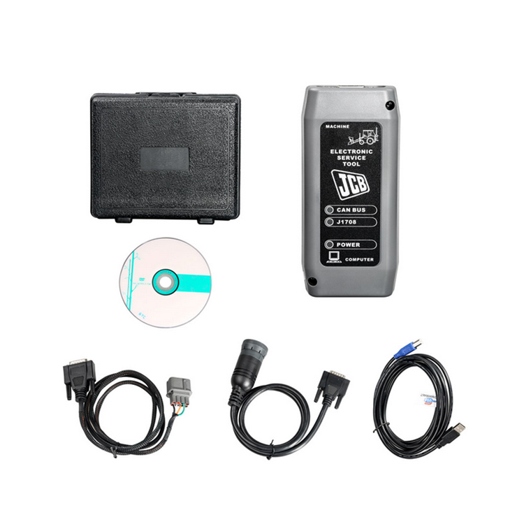
JCB Product Support Laptop Based Diagnostic Tool Manual Download
JCB Diagnostic Trouble Codes Download
JCB flash codes list Download
JCB JS-Excavator’s Fault Codes List Download
JCB v8+ Electrical Error Fault codes v1-07 Download
Troubleshooting/fault code,error kode JCB Excavator JS 200 JS 210 JS 220 JS 240 JS 260 Download
Livelink is a monitoring system that allows you to check the condition of equipment from anywhere in the world.
A special adapter connects to the equipment and transmits data to the JCB site via satellites and the cellular network, so that at any time, wherever you are, you can go to the site and find out
the current state of the observed JCB equipment.
In the GENERAL category, you can view help information, DLA adapter settings, Servicemaster program manual, as well as additional programs for diagnostics of
engines, transmissions and hydrostatic systems of such machines as FASTRAC T4 tractors, TELETRUK LPG loaders, Loadall 532H-537H telehandlers.
In order to start diagnostics or other procedures, you need to select the type of equipment from the corresponding category.
And then select the desired procedure from the available ones. For most types of equipment, in addition to diagnostics, you can configure the blocks, download new firmware and updates, view the
service history, decode error codes, do various tests, detailed help is also available in which you can see the location of components and wiring diagrams.
Please note that the list of available options for different types and models of equipment is different!
JCB Diagnostic Kit (DLA) is a multifunctional dealer scanner that reads diagnostic trouble codes, ranking them according to the degree of need for service on JCB equipment.
Main functional features:
reads fault codes and ranks them in order of importance.
calibrates, parameters and programs ECM units.
carries out a reset of service intervals.
Compatible with Jcb Service Master 2 software.
works with CAN protocol in OBD II system.
supplied with instructions for operation, repair and diagnostics of JCB equipment and engines Isuzu, Deutz, Cummins.
JCB Diagnostic Kit (DLA) Applicability
JCB agricultural machinery
Fastrac tractors (2000-3000, 3000 2 Series, 3000 Series 3, 7000-Series, 8250-Series 1, 8250 3 Series, 8000-Series 3).
Telescopic handlers (2007 -, 2007 +).
Wheeled backhoe loaders (Large, Large 2012+, Compact).
JC construction machinery
Backhoe loaders, tracked excavators (JS / JZ, JZ70).
Wheeled excavators, compact excavators (Mini / Midi) (801-8065, 8080-8085).
Telescopic handlers (2007 -, 2007 +).
Skidsteer loaders (Robot and others).
Telescopic handlers Teletrucks.
Wheeled backhoe loaders (Large, Large 2012+, Compact).
Frontal loaders.
Vibrating rollers.
Rough terrain forklifts.
JCB engines
JCB Dieselmax (MPS, OEM Base, G Drive).
JCB Ecomax (MPS, OEM Base, G Drive).
Equipment
JCB Diagnostic Kit (DLA) scanner.
USB cable.
DB9 cable.
9-pin adapter for German equipment.
8-pin cable.
JCB ServiceMaster 2 v10.3.1 software.
JCB Compact Service Manuals v50 [2011] (S1, S2, S3, S4, S5).
|
Tracked & Wheeled Excavators |
Extracted fromVersion 145 |
No of Error Codes in list 978 |
|
J1939 |
In Use? |
Reviewed/ |
Diagnostic Trouble |
Machine Reaction |
Extended Fault Text (Datalogger/Diagnostic Tools) |
|
0x00 |
Y |
55 |
P0001 |
Torque Reduction |
IMV driver fault is detected |
|
0x00 |
Y |
55 |
P0002 |
Torque Reduction |
Rail Pressure Negative Control Error During ‘IMV-Only’ control. PID controller not able to stabilise the |
|
0x00 |
Y |
55 |
P0002 |
Torque Reduction |
Rail pressure control error (pressure error too high). |
|
0x00 |
Y |
55 |
P0002 |
Delayed Engine Stop |
Rail Pressure Positive Control Error During ‘IMV-Only’ control. PID controller not able to stabilise the |
|
0x00 |
Y |
55 |
P0002 |
Torque Reduction |
Rail pressure control error (pressure error too low). |
|
0x00 |
Y |
55 |
P0003 |
Rail pressure control feedback low error |
|
|
0x00 |
Y |
55 |
P0003 |
Torque Reduction |
IMV driver fault is detected |
|
0x00 |
Y |
55 |
P0004 |
Torque Reduction |
IMV driver fault is detected |
|
0x00 |
Y |
55 |
P0004 |
Torque Reduction |
Rail pressure control feedback high error |
|
0x00 |
Y |
124 |
P0016 |
Cam Sensor Phase Shift |
|
|
0x00 |
Y |
124 |
P0045 |
VNT Control Fault |
|
|
0x00 |
Y |
124 |
P0045 |
Turbo EVRV Fault |
|
|
0x3D |
Y |
114 |
P0070-81 |
CAN bus message error from engine ECU |
|
|
0x3D |
Y |
114 |
P0070-87 |
CAN bus message error from engine ECU |
|
|
0x3D |
Y |
114 |
P0071-87 |
CAN bus message error for environment temperature from engine ECU |
|
|
0x00 |
Y |
55 |
P007A |
Torque Reduction |
TMAP (Intake Manifold 1 temp) Temperature Element sensor fault (ADC) |
|
0x00 |
Y |
55 |
P007C |
Torque Reduction |
TMAP (Intake Manifold 1 temp) Temperature Element sensor low fault |
|
0x00 |
Y |
55 |
P007D |
Torque Reduction |
TMAP (Intake Manifold 1 temp) Temperature Element sensor high fault |
|
0x00 |
Y |
55 |
P007E |
Torque Reduction |
TMAP (Intake Manifold 1 temp) Temperature Element sensor noise fault |
|
0x00 |
Y |
114 |
P0087 |
Torque Reduction |
Rail Pressure Control Error Positive |
|
0x00 |
Y |
55 |
P0087 |
Rail Pressure build low fault |
|
|
0x00 |
Y |
114 |
P0087 |
Rail Pressure build normal fault |
|
|
0x00 |
Y |
114 |
P0087 |
Torque Reduction_Delayed Engine Stop |
RPC Variable Limit Capacity (VLC) Torque reduction clamped |
|
0x00 |
Y |
124 |
P0087 |
Torque Reduction_Delayed Engine Stop |
Pressure Limiter Open |
|
0x00 |
Y |
114 |
P0087 |
Torque Reduction |
RPC Variable Limit Capacity (VLC) Torque reduction above its threshold |
|
0x00 |
Y |
114 |
P0088 |
Torque Reduction |
Rail pressure control error during HPV control (over max calibrated system pressure) |
|
0x00 |
Y |
114 |
P0088 |
Torque Reduction |
Rail pressure control error during IMV control (over max calibrated system pressure) |
|
0x00 |
Y |
55 |
P0088 |
Torque Reduction |
Rail pressure control undefined error (over max calibrated system pressure) |
|
0x00 |
Y |
114 |
P0088 |
Rail Pressure Control Error Negative |
|
|
0x00 |
Y |
124 |
P0088 |
Torque Reduction |
C/Rail pressure exceeds hi upper limit3 |
|
0x00 |
Y |
114 |
P0088 |
Rail Pressure overpressure timeout |
|
|
0x00 |
Y |
124 |
P0088 |
Torque Reduction |
Common Rail Pressure Rise㸦 1st Stage㸧 |
|
0x00 |
Y |
114 |
P0089 |
Rail Pressure control error |
|
|
0x00 |
Y |
114 |
P0089 |
Rail Pressure Negative Control Error During ‘HPV-Only’ control. PID controller not able to stabilise the |
|
0x00 |
Y |
114 |
P0089 |
Rail Pressure Positive Control Error During ‘HPV-Only’ control. PID controller not able to stabilise the |
|
|
0x00 |
Y |
55 |
P0089 |
Rail Pressure Negative Control Error During ‘IC & HMV’ control. PID controller not able to stabilise the |
|
|
0x00 |
Y |
114 |
P0089 |
Rail Pressure Positive Control Error During ‘IC & HMV’ control. PID controller not able to stabilise the |
|
|
0x00 |
Y |
114 |
P0089 |
Torque Reduction |
Rail Pressure Negative Control Error During ‘RVD-Only’ control. PID controller not able to stabilise the |
|
0x00 |
Y |
114 |
P0089 |
Delayed Engine Stop |
Rail Pressure Positive Control Error During ‘RVD-Only’ control. PID controller not able to stabilise the |
|
0x00 |
Y |
114 |
P0089 |
Torque Reduction |
Check that HPV is not stuck during IMV regulation. |
|
0x00 |
Y |
114 |
P0089 |
Torque Reduction |
HPV open loop slope fault detected |
|
0x00 |
Y |
124 |
P0089 |
Common Rail Pressure Fault (Excess Feed) |
|
|
0x00 |
Y |
55 |
P0090 |
Torque Reduction |
HPV driver in ECU fault detected |
|
0x00 |
Y |
55 |
P0091 |
Torque Reduction |
Check HPV regulation control trim low |
|
0x00 |
Y |
114 |
P0091 |
Torque Reduction |
Check HPV hardware current control trim low |
|
0x00 |
Y |
114 |
P0091 |
Torque Reduction |
HPV current feedback low fault detected |
|
0x00 |
Y |
124 |
P0091 |
Torque Reduction |
SCV Low Voltage Fault |
|
0x00 |
Y |
114 |
P0091 |
Torque Reduction |
HPV driver in ECU fault detected |
|
0x00 |
Y |
55 |
P0092 |
Torque Reduction |
Check HPV regulation control trim high. |
|
0x00 |
Y |
124 |
P0092 |
Torque Reduction_Delayed Engine Stop |
SCV High Voltage Fault |
|
0x00 |
Y |
114 |
P0092 |
Torque Reduction |
Check HPV hardware current control trim high |
|
0x00 |
Y |
114 |
P0092 |
Torque Reduction_Delayed Engine Stop |
HPV current feedback high fault detected |
|
0x00 |
Y |
114 |
P0092 |
Torque Reduction_Delayed Engine Stop |
HPV driver in ECU fault detected |
|
0x00 |
Y |
124 |
P0093 |
Common Rail Pressure Fall (No Feed) |
|
|
0x00 |
Y |
124 |
P0093 |
Common Rail Pressure Fault (Lack of Feed 2) |
|
|
0x00 |
Y |
55 |
P0095 |
Torque Reduction |
Intake manifold temperature (M2) signal sensor ADC fault (Intake Manifold 2 temp) |
|
0x00 |
Y |
55 |
P0096 |
Torque Reduction |
Intake manifold temperature sensor (M2) signal noise fault (Intake Manifold 2 temp) |
|
0x00 |
Y |
55 |
P0096 |
Torque Reduction |
Intake manifold temperature sensor (M2) signal plausibility fault (Intake Manifold 2 temp) |
|
0x00 |
Y |
55 |
P0097 |
Torque Reduction |
Intake manifold temperature sensor (M2) signal low fault (Intake Manifold 2 temp) |
|
0x00 |
Y |
55 |
P0098 |
Torque Reduction |
Intake manifold temperature sensor (M2) signal high signal fault (Intake Manifold 2 temp) |
|
0x3D |
Y |
114 |
P00B7-87 |
T4F Inducement |
CAN bus message error for coolant sensor from engine ECU |
|
0x00 |
Y |
55 |
P0100 |
Torque Reduction |
AMF High Side Driver fault Short Circuit To Ground (SC2G) |
|
0x00 |
Y |
114 |
P0100 |
Torque Reduction |
AMF fault (global). Set if plau, grad or electrical flt is present |
|
0x00 |
Y |
114 |
P0100 |
Torque Reduction |
AMF High Side Driver fault (Global |
|
0x00 |
Y |
114 |
P0100 |
Torque Reduction |
AMF High Side Driver fault Open Circuit (OC) Or Short Circuit to Battery (SC2VBAT) |
|
0x00 |
Y |
114 |
P0100 |
Torque Reduction |
AMF High Side Driver fault Short Circuit (SC) |
|
0x00 |
Y |
114 |
P0100 |
Torque Reduction |
AMF electrical sensor fault (ADC) |
|
0x00 |
Y |
124 |
P0101 |
MAF Sensor Fault |
|
|
0x00 |
Y |
124 |
P0102 |
Torque Reduction |
MAF Low Voltage Fault |
|
0x00 |
Y |
55 |
P0102 |
Torque Reduction |
AMF electrical sensor low fault |
|
0x00 |
Y |
124 |
P0103 |
Torque Reduction |
MAF High Voltage Fault |
|
0x00 |
Y |
55 |
P0103 |
Torque Reduction |
AMF electrical sensor high fault |
|
0x00 |
Y |
55 |
P0105 |
Torque Reduction |
Intake Manifold Absolute Pressure (MAP) sensor global fault |
|
0x00 |
Y |
55 |
P0106 |
Torque Reduction |
Intake Manifold Absolute Pressure (MAP) sensor signal drift low fault |
|
0x00 |
Y |
55 |
P0106 |
Torque Reduction |
Intake Manifold Absolute Pressure (MAP) sensor signal drift high fault |
|
0x00 |
Y |
55 |
P0106 |
Torque Reduction |
Intake Manifold Absolute Pressure (MAP) sensor signal plausibility fault |
|
0x00 |
Y |
55 |
P0106 |
Torque Reduction |
Intake Manifold Absolute Pressure (MAP) sensor signal plausibility high fault |
|
0x00 |
Y |
55 |
P0106 |
Torque Reduction |
Intake Manifold Absolute Pressure (MAP) sensor signal plausibility low fault |
|
0x00 |
Y |
124 |
P0107 |
Boost Pressure Sensor Fault 㸦 Low Voltage Fault |
|
|
0x00 |
Y |
124 |
P0108 |
Boost Pressure Sensor Fault 㸦 High Voltage Fault㸧 |
|
|
0x00 |
Y |
55 |
P0110 |
Torque Reduction |
Inlet Air Temperature (IAT) sensor signal ADC fault detected |
|
0x00 |
Y |
124 |
P0112 |
Torque Reduction |
Inlet Air Temperature (IAT) sensor signal low fault detected |
|
0x00 |
Y |
124 |
P0113 |
Torque Reduction |
Inlet Air Temperature (IAT) sensor signal high fault detected |
|
0x00 |
Y |
55 |
P0115 |
Torque Reduction |
Coolant sensor signal fault |
|
0x00 |
Y |
55 |
P0116 |
Coolant sensor fault (plausibility) |
|
|
0x00 |
Y |
124 |
P0116 |
Torque Reduction |
Coolant temperature sensor performance invalid |
|
0x00 |
Y |
55 |
P0117 |
Coolant sensor signal low fault |
|
|
0x00 |
Y |
124 |
P0117 |
Coolant temperature sensor signal too low |
|
|
0x00 |
Y |
124 |
P0118 |
Coolant sensor signal high fault |
|
|
0x00 |
Y |
124 |
P0122 |
Intake Throttle Position Low Voltage Fault |
|
|
0x00 |
Y |
124 |
P0123 |
Intake Throttle Position High Voltage Fault |
|
|
0x3D |
Y |
114 |
P0129-87 |
Erroneous signal for Barometric Pressure. |
|
|
0x3D |
Y |
114 |
P0129-87 |
CAN bus message error for environment pressure from engine ECU |
|
|
0x00 |
Y |
55 |
P0133 |
Wide Range Air Fuel control (WRAF) fault: Response |
|
|
0x00 |
Y |
55 |
P0180 |
Torque Reduction |
Fuel temperature ADC fault |
|
J1939 |
In Use? |
Added |
Diagnostic Trouble |
Machine Reaction |
Extended Fault Text (Datalogger/Diagnostic Tools) |
|
0x00 |
Y |
124 |
P0181 |
Torque Reduction |
Fuel Temperature Sensor Fault |
|
0x00 |
Y |
55 |
P0181 |
Torque Reduction |
Fuel temperature sensor gradient fault |
|
0x3D |
Y |
114 |
P0181-87 |
CAN bus message error for fuel temperature from engine ECU |
|
|
0x00 |
Y |
124 |
P0182 |
Torque Reduction |
Fuel temperature sensor low fault |
|
0x00 |
Y |
124 |
P0183 |
Torque Reduction |
Fuel temperature sensor high fault |
|
0x00 |
Y |
55 |
P0190 |
Torque Reduction_Limp Home (Idle Only) |
Rail Pressure Sensor signal grad fault |
|
0x00 |
Y |
55 |
P0191 |
Torque Reduction_Limp Home (Idle Only) |
Rail Pressure Sensor fault. Above maximum threshold (out of range at key-on) |
|
0x00 |
Y |
55 |
P0191 |
Torque Reduction_Limp Home (Idle Only) |
Rail Pressure Sensor fault. Below minimum threshold (out of range at key-on) |
|
0x00 |
Y |
55 |
P0191 |
Torque Reduction_Limp Home (Idle Only) |
Rail Pressure Sensor fault. Exceeds threshold (out of range at key-on) |
|
0x00 |
Y |
124 |
P0192 |
Torque Reduction_Limp Home (Idle Only) |
Rail Pressure Sensor signal low fault |
|
0x00 |
Y |
124 |
P0193 |
Torque Reduction_Limp Home (Idle Only) |
Rail Pressure Sensor signal high fault |
|
0x00 |
Y |
55 |
P0194 |
Torque Reduction_Limp Home (Idle Only)_Delayed |
Rail Pressure Sensor signal drop fault |
|
0x00 |
Y |
55 |
P0195 |
Torque Reduction |
Oil temperature sensor signal global fault |
|
0x00 |
Y |
114 |
P0195 |
Torque Reduction |
Oil temperature sensor signal external voltage (V-Ref) fault |
|
0x00 |
Y |
55 |
P0196 |
Torque Reduction |
Oil temperature sensor signal plausability fault |
|
0x00 |
Y |
55 |
P0196 |
Torque Reduction |
Oil temperature sensor signal gradient fault |
|
0x3D |
Y |
114 |
P0196-87 |
CAN bus message error for oil temperature from engine ECU |
|
|
0x00 |
Y |
55 |
P0197 |
Torque Reduction |
Oil temperature sensor signal low fault |
|
0x00 |
Y |
55 |
P0198 |
Torque Reduction |
Oil temperature sensor signal high fault |
|
0x00 |
Y |
55 |
P0201 |
Injector 2 Open Circuit fault (OC) |
|
|
0x00 |
Y |
55 |
P0201 |
Injector in Cylinder 1 Short Circuit HSD to LSD |
|
|
0x00 |
Y |
124 |
P0201 |
Injector in Cylinder 1 Open Circuit fault (OC) |
|
|
0x00 |
Y |
124 |
P0202 |
Injector 1 Open Circuit fault (OC) |
|
|
0x00 |
Y |
55 |
P0202 |
Injector in Cylinder 2 Short Circuit HSD to LSD |
|
|
0x00 |
Y |
88 |
P0202 |
Injector in Cylinder 2 Open Circuit fault (OC) |
|
|
0x00 |
Y |
124 |
P0203 |
Injector 3 Open Circuit fault (OC) |
|
|
0x00 |
Y |
55 |
P0203 |
Injector in Cylinder 3 Short Circuit HSD to LSD |
|
|
0x00 |
Y |
88 |
P0203 |
Injector in Cylinder 3 Open Circuit fault (OC) |
|
|
0x00 |
Y |
124 |
P0204 |
Injector 0 Open Circuit fault (OC) |
|
|
0x00 |
Y |
55 |
P0204 |
Injector in Cylinder 4 Short Circuit HSD to LSD |
|
|
0x00 |
Y |
88 |
P0204 |
Injector in Cylinder 4 Open Circuit fault (OC) |
|
|
0x00 |
Y |
124 |
P0205 |
Injector in Cylinder 5 Open Circuit fault (OC) |
|
|
0x00 |
Y |
88 |
P0205 |
Injector in Cylinder 5 Short Circuit HSD to LSD |
|
|
0x00 |
Y |
124 |
P0206 |
Injector in Cylinder 6 Open Circuit fault (OC) |
|
|
0x00 |
Y |
88 |
P0206 |
Injector in Cylinder 6 Short Circuit HSD to LSD |
|
|
0x00 |
Y |
124 |
P0217 |
Torque Reduction |
Coolant temperature exceeds upper limit |
|
0x00 |
Y |
124 |
P0219 |
Torque Reduction |
Engine overspeed condition |
|
0x00 |
Y |
124 |
P0234 |
Torque Reduction |
Turbo Over Boost |
|
0x00 |
Y |
55 |
P0235 |
Torque Reduction |
Boosted air pressure sensor fault: ADC |
|
0x00 |
Y |
55 |
P0237 |
Torque Reduction |
Boosted air pressure sensor low fault |
|
0x00 |
Y |
55 |
P0238 |
Torque Reduction |
Boosted air pressure sensor high fault |
|
0x00 |
Y |
55 |
P0252 |
Torque Reduction |
Rail pressure control error (IMV current trim drift). |
|
0x00 |
Y |
114 |
P0252 |
Torque Reduction |
Rail pressure control error (IMV current trim drift). |
|
0x00 |
Y |
114 |
P0252 |
Torque Reduction |
Rail pressure control error (IMV current trim drift). |
|
0x00 |
Y |
114 |
P0252 |
Torque Reduction |
Rail pressure control error (IMV current trim drift). |
|
0x00 |
Y |
114 |
P0252 |
Torque Reduction |
Rail pressure control error (IMV current trim drift). |
|
0x00 |
Y |
55 |
P0253 |
Torque Reduction_Delayed Engine Stop |
Rail pressure control by the IMV. Occurs at high fuel delivery for low (negative) current trim |
|
0x00 |
Y |
55 |
P0254 |
Torque Reduction_Delayed Engine Stop |
Rail pressure control fault by the IMV. Occurs at high fuel delivery for high (positive) current trim |
|
0x00 |
Y |
55 |
P0261 |
Torque Reduction |
Injector and wiring harness resistance too high/low (inj 2) |
|
0x00 |
Y |
55 |
P0261 |
Torque Reduction |
Injector and wiring harness resistance too high/low (inj 2) |
|
0x00 |
Y |
55 |
P0262 |
Torque Reduction |
Injector and wiring harness resistance drop (Inj 2) |
|
0x00 |
Y |
55 |
P0262 |
Torque Reduction |
Injector and wiring harness resistance drop (Inj 2) |
|
0x00 |
Y |
55 |
P0263 |
Torque Reduction |
Cylinder balancing fault injector 2 stuck closed |
|
0x00 |
Y |
55 |
P0264 |
Torque Reduction |
Injector and wiring harness resistance too high/low (inj 1) |
|
0x00 |
Y |
55 |
P0264 |
Torque Reduction |
Injector and wiring harness resistance too high/low (inj 1) |
|
0x00 |
Y |
55 |
P0265 |
Torque Reduction |
Injector and wiring harness resistance drop (Inj 1) |
|
0x00 |
Y |
55 |
P0265 |
Torque Reduction |
Injector and wiring harness resistance drop (Inj 1) |
|
0x00 |
Y |
55 |
P0266 |
Torque Reduction |
Cylinder balancing fault injector 1 stuck closed |
|
0x00 |
Y |
55 |
P0267 |
Torque Reduction |
Injector and wiring harness resistance too high/low (inj 3) |
|
0x00 |
Y |
55 |
P0267 |
Torque Reduction |
Injector and wiring harness resistance too high/low (inj 3) |
|
0x00 |
Y |
55 |
P0268 |
Torque Reduction |
Injector and wiring harness resistance drop (Inj 3) |
|
0x00 |
Y |
55 |
P0268 |
Torque Reduction |
Injector and wiring harness resistance drop (Inj 3) |
|
0x00 |
Y |
55 |
P0269 |
Torque Reduction |
Cylinder balancing fault injector 3 stuck closed |
|
0x00 |
Y |
55 |
P0270 |
Torque Reduction |
Injector drift fault detection on Injector 2. Fault which is set when the Injector 2 MDP trim exceeds the |
|
0x00 |
Y |
55 |
P0270 |
Torque Reduction |
Injector drift fault detection on Injector 2. Fault which is set when Injector 2 MDP trim exceeds the |
|
0x00 |
Y |
55 |
P0271 |
Torque Reduction |
Injector and wiring harness resistance drop (Inj 0) |
|
0x00 |
Y |
55 |
P0271 |
Torque Reduction |
Injector and wiring harness resistance drop (Inj 0) |
|
0x00 |
Y |
55 |
P0272 |
Torque Reduction |
Cylinder balancing fault injector 0 stuck closed |
|
0x00 |
Y |
88 |
P0273 |
Injector and wiring harness resistance too high/low (inj 1) |
|
|
0x00 |
Y |
88 |
P0273 |
Injector and wiring harness resistance too high/low (inj 1) |
|
|
0x00 |
Y |
88 |
P0274 |
Injector and wiring harness resistance drop (Inj 1) |
|
|
0x00 |
Y |
88 |
P0274 |
Injector and wiring harness resistance drop (Inj 1) |
|
|
0x00 |
Y |
88 |
P0275 |
Cylinder balancing fault injector 1 stuck closed |
|
|
0x00 |
Y |
88 |
P0276 |
Injector and wiring harness resistance too high/low (inj 3) |
|
|
0x00 |
Y |
88 |
P0276 |
Injector and wiring harness resistance too high/low (inj 3) |
|
|
0x00 |
Y |
88 |
P0277 |
Injector and wiring harness resistance drop (Inj 3) |
|
|
0x00 |
Y |
88 |
P0277 |
Injector and wiring harness resistance drop (Inj 3) |
|
|
0x00 |
Y |
88 |
P0278 |
Cylinder balancing fault injector 3 stuck closed |
|
|
0x00 |
Y |
124 |
P0299 |
Torque Reduction |
Turbo Low Boost |
|
0x00 |
Y |
55 |
P029A |
Injector drift fault detection on Injector 3. Fault which is set when the Injector 3 MDP trim exceeds the |
|
|
0x00 |
Y |
55 |
P029A |
Injector drift fault detection on Injector 2. Fault which is set when the Injector 2 MDP trim exceeds the |
|
|
0x00 |
Y |
55 |
P029A |
Injector drift fault detection on Injector 2. Fault which is set when Injector 2 MDP trim exceeds the |
|
|
0x00 |
Y |
55 |
P029B |
Fault which is set when the Injector 3 absolute MDP value is below a calibrated threshold |
|
|
0x00 |
Y |
55 |
P029B |
Injector drift fault detection on Injector 2. Fault which is set when Injector 2 MDP trim exceeds the |
|
|
0x00 |
Y |
55 |
P029B |
Injector drift fault detection on Injector 2. Fault which is set when Injector 2 MDP trim exceeds the |
|
|
0x00 |
Y |
55 |
P029B |
Injector drift fault detection on Injector 2. Fault which is set when Injector 2 MDP trim exceeds the |
|
J1939 |
In Use? |
Added |
Diagnostic Trouble |
Machine Reaction |
Extended Fault Text (Datalogger/Diagnostic Tools) |
|
0x00 |
Y |
55 |
P029E |
Injector drift fault detection on Injector 1. Fault which is set when the Injector 1 MDP trim exceeds the |
|
|
0x00 |
Y |
55 |
P029E |
Injector drift fault detection on Injector 1. Fault which is set when the Injector 1 MDP trim exceeds the |
|
|
0x00 |
Y |
55 |
P029E |
Injector drift fault detection on Injector 1. Fault which is set when Injector 1 MDP trim exceeds the |
|
|
0x00 |
Y |
55 |
P029F |
Fault which is set when the Injector 2 absolute MDP value is below a calibrated threshold |
|
|
0x00 |
Y |
55 |
P029F |
Injector drift fault detection on Injector 1. Fault which is set when Injector 1 MDP trim exceeds the |
|
|
0x00 |
Y |
55 |
P029F |
Injector drift fault detection on Injector 1. Fault which is set when Injector 1 MDP trim exceeds the |
|
|
0x00 |
Y |
55 |
P029F |
Injector drift fault detection on Injector 1. Fault which is set when Injector 1 MDP trim exceeds the |
|
|
0x00 |
Y |
55 |
P02A2 |
Injector drift fault detection on Injector 2. Fault which is set when the Injector 2 MDP trim exceeds the |
|
|
0x00 |
Y |
55 |
P02A2 |
Injector drift fault detection on Injector 2. Fault which is set when the Injector 2 MDP trim exceeds the |
|
|
0x00 |
Y |
55 |
P02A2 |
Injector drift fault detection on Injector 2. Fault which is set when Injector 2 MDP trim exceeds the |
|
|
0x00 |
Y |
55 |
P02A3 |
Fault which is set when the Injector 4 absolute MDP value is below a calibrated threshold |
|
|
0x00 |
Y |
55 |
P02A3 |
Injector drift fault detection on Injector 3. Fault which is set when Injector 3 MDP trim exceeds the |
|
|
0x00 |
Y |
55 |
P02A3 |
Injector drift fault detection on Injector 3. Fault which is set when Injector 3 MDP trim exceeds the |
|
|
0x00 |
Y |
55 |
P02A3 |
Injector drift fault detection on Injector 3. Fault which is set when Injector 3 MDP trim exceeds the |
|
|
0x00 |
Y |
55 |
P02A6 |
Injector drift fault detection on Injector 0. Fault which is set when the Injector 0 MDP trim exceeds the |
|
|
0x00 |
Y |
55 |
P02A6 |
Injector drift fault detection on Injector 0. Fault which is set when the Injector 0 MDP trim exceeds the |
|
|
0x00 |
Y |
55 |
P02A6 |
Injector drift fault detection on Injector 0. Fault which is set when Injector 0 MDP trim exceeds the |
|
|
0x00 |
Y |
55 |
P02A7 |
Fault which is set when the Injector 1 absolute MDP value is below a calibrated threshold |
|
|
0x00 |
Y |
55 |
P02A7 |
Injector drift fault detection on Injector 0. Fault which is set when Injector 0 MDP trim exceeds the |
|
|
0x00 |
Y |
55 |
P02A7 |
Injector drift fault detection on Injector 0. Fault which is set when Injector 0 MDP trim exceeds the |
|
|
0x00 |
Y |
55 |
P02A7 |
Injector drift fault detection on Injector 0. Fault which is set when Injector 0 MDP trim exceeds the |
|
|
0x00 |
Y |
88 |
P02AA |
Injector drift fault detection on Injector 1. Fault which is set when the Injector 1 MDP trim exceeds the |
|
|
0x00 |
Y |
88 |
P02AA |
Injector drift fault detection on Injector 1. Fault which is set when the Injector 1 MDP trim exceeds the |
|
|
0x00 |
Y |
88 |
P02AA |
Injector drift fault detection on Injector 1. Fault which is set when Injector 1 MDP trim exceeds the |
|
|
0x00 |
Y |
88 |
P02AB |
Fault which is set when the Injector 1 absolute MDP value is below a calibrated threshold |
|
|
0x00 |
Y |
88 |
P02AB |
Injector drift fault detection on Injector 1. Fault which is set when Injector 1 MDP trim exceeds the |
|
|
0x00 |
Y |
88 |
P02AB |
Injector drift fault detection on Injector 1. Fault which is set when Injector 1 MDP trim exceeds the |
|
|
0x00 |
Y |
88 |
P02AB |
Injector drift fault detection on Injector 1. Fault which is set when Injector 1 MDP trim exceeds the |
|
|
0x00 |
Y |
88 |
P02AE |
Injector drift fault detection on Injector 3. Fault which is set when the Injector 3 MDP trim exceeds the |
|
|
0x00 |
Y |
88 |
P02AE |
Injector drift fault detection on Injector 3. Fault which is set when the Injector 3 MDP trim exceeds the |
|
|
0x00 |
Y |
88 |
P02AE |
Injector drift fault detection on Injector 3. Fault which is set when Injector 3 MDP trim exceeds the |
|
|
0x00 |
Y |
88 |
P02AF |
Fault which is set when the Injector 3 absolute MDP value is below a calibrated threshold |
|
|
0x00 |
Y |
88 |
P02AF |
Injector drift fault detection on Injector 3. Fault which is set when Injector 3 MDP trim exceeds the |
|
|
0x00 |
Y |
88 |
P02AF |
Injector drift fault detection on Injector 3. Fault which is set when Injector 3 MDP trim exceeds the |
|
|
0x00 |
Y |
88 |
P02AF |
Injector drift fault detection on Injector 3. Fault which is set when Injector 3 MDP trim exceeds the |
|
|
0x3D |
Y |
114 |
P0321-87 |
CAN bus message error for engine speed from engine ECU |
|
|
0x00 |
Y |
55 |
P0325 |
Accelerometer fault (signal/noise ratio too low in idle) |
|
|
0x00 |
Y |
94 |
P0330 |
Knock Sensor 1 Circuit |
|
|
0x00 |
Y |
124 |
P0335 |
Crank Sensor Fault 㸦 No Signal㸧 |
|
|
0x00 |
Y |
55 |
P0335 |
Crankshaft Position Sensor «A» Circuit |
|
|
0x00 |
Y |
114 |
P0335 |
Crank signal overspeed fault |
|
|
0x00 |
Y |
124 |
P0336 |
Torque Reduction |
Crank Sensor Fault 㸦 Signal Fault㸧 |
|
0x00 |
Y |
55 |
P0340 |
Torque Reduction |
Cam signal last learnt value is outside of limits |
|
0x00 |
Y |
124 |
P0340 |
Torque Reduction |
G Sensor Fault (No Signal) |
|
0x00 |
Y |
55 |
P0341 |
Torque Reduction |
Cam signal drift higher than threshold |
|
0x00 |
Y |
124 |
P0341 |
Torque Reduction |
G Sensor Fault (Abnormal Signal㸧 |
|
0x00 |
Y |
55 |
P0341 |
Camshaft Position Sensor A Circuit Range / Performance |
|
|
0x00 |
Y |
55 |
P0341 |
Torque Reduction |
Cam signal lost (no Cam signal seen in 2 Crank rotations) |
|
0x00 |
Y |
55 |
P0341 |
Torque Reduction |
Cam signal fault (missing event within the expected window) |
|
0x00 |
Y |
55 |
P0341 |
Cam signal fault (overspeed detected) |
|
|
0x3D |
Y |
114 |
P0350-02 |
Error monitoring for system protection based on ignition switch input |
|
|
0x00 |
Y |
55 |
P0371 |
Torque Reduction |
Crank signal is too close to the previous one |
|
0x00 |
Y |
55 |
P0372 |
Torque Reduction |
Elapsed time between CPS events is too high |
|
0x00 |
Y |
55 |
P0374 |
Torque Reduction |
Crank signal lost (no CPS signal seen in 1 Cam rotation) |
|
0x00 |
Y |
124 |
P0380 |
Glow Plug/Heater Circuit «A» |
|
|
0x00 |
Y |
55 |
P0380 |
Glow Plug/Heater Circuit «A» |
|
|
0x00 |
Y |
124 |
P0381 |
Glow Plug Fault |
|
|
0x00 |
Y |
55 |
P0383 |
Glow Plug Control Module Control Circuit Low |
|
|
0x00 |
Y |
55 |
P0384 |
Glow Plug Control Module Control Circuit High |
|
|
0x00 |
Y |
55 |
P0400 |
Torque Reduction / T4F Inducement |
EGR flow reached its limit |
|
0x00 |
Y |
124 |
P0401 |
EGR Gas flow Fault |
|
|
0x00 |
Y |
124 |
P0404 |
EGR Valve Control Fault |
|
|
0x00 |
Y |
124 |
P0404 |
EGR Open Defective |
|
|
0x00 |
Y |
94 |
P0404 |
Exhaust Gas Recirculation «A» Control Circuit Range/Performance |
|
|
0x00 |
Y |
55 |
P0405 |
Exhaust Gas Recirculation Sensor «A» Circuit Low |
|
|
0x00 |
Y |
55 |
P0406 |
Exhaust Gas Recirculation Sensor «A» Circuit High |
|
|
0x00 |
Y |
124 |
P0409 |
EGR Position Sensor Fault 㸦 Brushless Specification㸧 |
|
|
0x00 |
Y |
124 |
P041C |
Manifold Temperature Sensor Fault 㸦 High Voltage |
|
|
0x00 |
Y |
124 |
P041D |
Manifold Temperature Sensor Fault 㸦 Low Voltage Fault㸧 |
|
|
0x00 |
Y |
124 |
P0426 |
DPF Exhaust Temperature 1 High |
|
|
0x00 |
Y |
124 |
P0426 |
DPF Exhaust Temperature 1Low |
|
|
0x00 |
Y |
124 |
P0427 |
Exhaust Temperature Sensor 1Low Voltage Fault |
|
|
0x00 |
Y |
124 |
P0428 |
Exhaust Temperature Sensor 1High Voltage Fault |
|
|
0x00 |
Y |
124 |
P042B |
DPF Exhaust Temperature 2 High |
|
|
0x00 |
Y |
124 |
P042B |
DPF Exhaust Temperature 2 Low |
|
|
0x00 |
Y |
124 |
P042C |
Exhaust Temperature Sensor 2 Low Voltage Fault |
|
|
0x00 |
Y |
124 |
P042D |
Exhaust Temperature Sensor 2 High Voltage Fault |
|
|
0x00 |
Y |
94 |
P046D |
Exhaust Gas Recirculation Sensor «A» Circuit Intermittent/Erratic |
|
|
0x00 |
Y |
55 |
P0470 |
Torque Reduction |
Exhaust manifold pressure (P3) signal ADC fault |
|
0x00 |
Y |
55 |
P0472 |
Torque Reduction |
Exhaust manifold pressure (P3) signal low fault |
|
0x00 |
Y |
55 |
P0472 |
Torque Reduction |
Exhaust manifold pressure (P3) signal drifted low |
|
0x00 |
Y |
55 |
P0473 |
Torque Reduction |
Exhaust manifold pressure (P3) signal high fault |
|
0x00 |
Y |
55 |
P0473 |
Torque Reduction |
Exhaust manifold pressure (P3) signal drifted high |
|
0x00 |
Y |
124 |
P0512 |
Starter Switch Fault |
|
|
0x00 |
Y |
55 |
P0520 |
Low oil pressure Lamp/Gauge drive open circuit (OC) |
|
|
0x00 |
Y |
55 |
P0520 |
Low oil pressure Lamp/Gauge drive short circuit (SC) |
|
|
0x00 |
Y |
55 |
P0520 |
Low oil pressure Lamp/Gauge drive short circuit to ground (SC2GND) |
|
|
0x00 |
Y |
55 |
P0520 |
Low oil pressure Lamp/Gauge drive short circuit to battery voltage (SC2VBATT) |
|
|
0x00 |
Y |
55 |
P0521 |
Oil pressure sensor signal global fault |
|
|
0x00 |
Y |
124 |
P0522 |
None |
Engine Oil Pressure Sensor Fault (Low Voltage Fault) |
|
0x00 |
Y |
88 |
P0522 |
Torque Reduction |
Oil Pressure Signal Out of Range High |
|
0x00 |
Y |
55 |
P0522 |
High Oil Pressure During Engine Running |
|
|
0x00 |
Y |
55 |
P0523 |
Low Oil Pressure During Engine Running |
|
|
0x27 |
Y |
91 |
P0523 |
Low Oil Pressure During Engine Running |
|
|
0x00 |
Y |
124 |
P0523 |
Engine Oil Pressure Sensor Fault (High Voltage Fault) |
|
|
0x00 |
Y |
88 |
P0523 |
Torque Reduction |
Oil Pressure Signal Out of Range Low |
|
0x00 |
Y |
88 |
P0523 |
Low Oil Pressure During Engine Running |
|
|
0x00 |
Y |
55 |
P0544 |
Torque Reduction |
Turbo in temperature fault |
|
0x00 |
Y |
55 |
P0545 |
Torque Reduction |
Turbo in temperature count low fault |
|
0x00 |
Y |
55 |
P0546 |
Torque Reduction |
Turbo in temperature count high fault |
|
0x00 |
Y |
124 |
P0560 |
12V Power Supply Voltage Fault |
|
|
0x00 |
Y |
55 |
P0562 |
Torque Reduction |
Battery voltage monitoring signal low fault |
|
0x00 |
Y |
124 |
P0562 |
Torque Reduction |
System Power Supply Low Voltage Fault |
|
0x3D |
Y |
114 |
P0562-16 |
Low battery voltage |
|
|
0x3D |
Y |
114 |
P0562-02 |
Fault due to low or high battery voltage supply to DCU |
|
|
0x00 |
Y |
55 |
P0563 |
Torque Reduction |
Battery voltage monitoring signal high fault |
|
0x00 |
Y |
124 |
P0563 |
Torque Reduction |
System Power Supply High Voltage Fault |
|
0x3D |
Y |
114 |
P0563-17 |
High battery voltage |
|
|
0x00 |
Y |
124 |
P0601 |
Torque Reduction |
ROM Fault |
|
0x00 |
Y |
124 |
P0602 |
Limp Home (Idle Only) |
QR Code Error |
|
0x00 |
Y |
114 |
P0602 |
Limp Home (Idle Only) |
C2I data not programmed |
|
0x00 |
Y |
55 |
P0602 |
Limp Home (Idle Only) |
C2I data not programmed |
|
0x00 |
Y |
114 |
P0602 |
Limp Home (Idle Only) |
C2I data not programmed |
|
0x00 |
Y |
114 |
P0602 |
Limp Home (Idle Only) |
C2I data not programmed |
|
0x00 |
Y |
114 |
P0602 |
Limp Home (Idle Only)_Engine Stop |
RAM corruption affecting Injector C2I data |
|
0x00 |
Y |
114 |
P0602 |
Functional Safety Fault |
|
|
0x00 |
Y |
55 |
P0602 |
Limp Home (Idle Only) |
Functional Safety Fault |
|
0x00 |
Y |
55 |
P0603 |
Engine Stop |
ECU memory integrity fault (data / cal integrity) |
|
0x00 |
Y |
55 |
P0604 |
Engine Stop |
ECU memory integrity fault (RAM integrity) |
|
0x00 |
Y |
124 |
P0604 |
Engine Stop |
RAM Fault |
|
0x00 |
Y |
55 |
P0605 |
Engine Stop |
ECU memory integrity fault (code integrity) |
|
0x00 |
Y |
55 |
P0606 |
Engine Stop |
Functional Safety Fault |
|
0x00 |
Y |
55 |
P0606 |
Engine Stop |
Functional Safety Fault |
|
0x00 |
Y |
55 |
P0606 |
Engine Stop |
Functional Safety Fault |
|
0x00 |
Y |
55 |
P0606 |
Engine Stop |
Functional Safety Fault |
|
0x00 |
Y |
55 |
P0606 |
Engine Stop |
Functional Safety Fault |
|
0x00 |
Y |
124 |
P0606 |
Engine Stop |
CPU Fault |
|
0x00 |
Y |
124 |
P0606 |
Engine Stop |
CPU Monitoring IC Fault |
|
0x00 |
Y |
55 |
P0606 |
Engine Stop |
Functional Safety Fault |
|
0x3D |
Y |
114 |
P0606-02 |
Peripheral monitoring error on DCU |
|
|
0x00 |
Y |
55 |
P0607 |
Engine Stop |
Functional Safety Fault |
|
0x00 |
Y |
55 |
P0607 |
Torque Reduction |
Throttle H-Bridge driver in ECU fault: Over temperature |
|
0x00 |
Y |
55 |
P060A |
Engine Stop |
Functional Safety Fault |
|
0x00 |
Y |
55 |
P060A |
Engine Stop |
Functional Safety Fault |
|
0x00 |
Y |
55 |
P060A |
Engine Stop |
Functional Safety Fault |
|
0x00 |
Y |
55 |
P060A |
Engine Stop |
Functional Safety Fault |
|
0x00 |
Y |
55 |
P060A |
Engine Stop |
Functional Safety Fault |
|
0x00 |
Y |
55 |
P060A |
Engine Stop |
Functional Safety Fault |
|
0x00 |
Y |
55 |
P060A |
Engine Stop |
Functional Safety Fault |
|
0x00 |
Y |
55 |
P060A |
Engine Stop |
Functional Safety Fault |
|
0x3D |
Y |
114 |
P060A-00 |
Monitoring error on DCU |
|
|
0x00 |
Y |
124 |
P060B |
A/D Conversion Fault |
|
|
0x00 |
Y |
55 |
P060B |
Limp Home (Idle Only)_Engine Stop |
ADC circuit fault (Global) |
|
0x00 |
Y |
55 |
P060B |
Torque Reduction |
HPV current feedback ADC fault detected |
|
0x00 |
Y |
55 |
P060B |
Internal Control Module A/D Processing Performance |
|
|
0x00 |
Y |
55 |
P060B |
Torque Reduction |
Functional Safety Fault |
|
SA (hex) |
In Use? |
Added |
Code |
Machine Reaction |
Extended Fault Text (Datalogger/Diagnostic Tools) |
|
0x00 |
Y |
55 |
P060B |
Torque Reduction |
Functional Safety Fault |
|
0x00 |
Y |
55 |
P060B |
Torque Reduction |
Functional Safety Fault |
|
0x00 |
Y |
55 |
P060C |
Engine Stop |
Functional Safety Fault |
|
0x00 |
Y |
55 |
P060C |
Engine Stop |
Functional Safety Fault |
|
0x00 |
Y |
55 |
P060C |
Engine Stop |
Functional Safety Fault |
|
0x00 |
Y |
55 |
P060C |
Engine Stop |
Functional Safety Fault |
|
0x00 |
Y |
55 |
P060C |
Engine Stop |
Functional Safety Fault |
|
0x00 |
Y |
55 |
P060C |
Engine Stop |
Functional Safety Fault |
|
0x00 |
Y |
55 |
P060C |
Engine Stop |
Functional Safety Fault |
|
0x00 |
Y |
55 |
P060C |
Engine Stop |
Functional Safety Fault |
|
0x00 |
Y |
55 |
P060C |
Engine Stop |
Functional Safety Fault |
|
0x3D |
Y |
114 |
P060C-00 |
DCU software reset performed |
|
|
0x3D |
Y |
114 |
P060C-41 |
T4F Inducement |
DCU software reset performed |
|
0x3D |
Y |
114 |
P060C-94 |
DCU software reset performed |
|
|
0x3D |
Y |
114 |
P060C-68 |
DCU software reset performed |
|
|
0x00 |
Y |
55 |
P060D |
Engine Stop |
Functional Safety Fault |
|
0x00 |
Y |
55 |
P060D |
Engine Stop |
Functional Safety Fault |
|
0x00 |
Y |
55 |
P060D |
Torque Reduction |
Functional Safety Fault |
|
0x00 |
Y |
55 |
P060D |
Torque Reduction |
Functional Safety Fault |
|
0x00 |
Y |
55 |
P060E |
Torque Reduction |
Functional Safety Fault |
|
0x00 |
Y |
55 |
P0612 |
Fuel Injector Control Module Relay Control |
|
|
0x00 |
Y |
55 |
P0612 |
Fuel Injector Control Module Relay Control |
|
|
0x00 |
Y |
55 |
P0612 |
Fuel Injector Control Module Relay Control |
|
|
0x00 |
Y |
55 |
P0612 |
Fuel Injector Control Module Relay Control |
|
|
0x00 |
Y |
124 |
P0615 |
Starter Relay Circuit |
|
|
0x00 |
Y |
55 |
P061A |
Functional Safety Fault |
|
|
0x00 |
Y |
55 |
P061B |
Torque Reduction |
Functional Safety Fault |
|
0x00 |
Y |
55 |
P061C |
Functional Safety Fault |
|
|
0x00 |
Y |
55 |
P061E |
Functional Safety Fault |
|
|
0x00 |
Y |
55 |
P061E |
Functional Safety Fault |
|
|
0x00 |
Y |
55 |
P0627 |
Torque Reduction |
Lift pump global fault |
|
0x00 |
Y |
55 |
P0628 |
Torque Reduction |
Lift pump global fault |
|
0x00 |
Y |
55 |
P0629 |
Torque Reduction |
Lift pump global fault |
|
0x00 |
Y |
55 |
P062B |
Torque Reduction |
Functional Safety Fault |
|
0x00 |
Y |
55 |
P062B |
Torque Reduction |
Functional Safety Fault |
|
0x00 |
Y |
55 |
P062B |
Torque Reduction |
Functional Safety Fault |
|
0x00 |
Y |
55 |
P062B |
Torque Reduction |
Functional Safety Fault |
|
0x00 |
Y |
55 |
P062B |
Torque Reduction |
Functional Safety Fault |
|
0x00 |
Y |
55 |
P062B |
Torque Reduction |
Functional Safety Fault |
|
0x00 |
Y |
55 |
P062B |
Torque Reduction |
Functional Safety Fault |
|
0x00 |
Y |
55 |
P062B |
Torque Reduction |
Functional Safety Fault |
|
0x00 |
Y |
55 |
P062B |
Torque Reduction |
Functional Safety Fault |
|
0x00 |
Y |
55 |
P062B |
Torque Reduction |
Functional Safety Fault |
|
0x00 |
Y |
55 |
P062B |
Torque Reduction |
Functional Safety Fault |
|
0x00 |
Y |
55 |
P062D |
Delayed Engine Stop |
Injector Bank 0 fault shorted to ground (SC2VBAT) |
|
0x00 |
Y |
55 |
P062D |
Delayed Engine Stop |
Injector Bank 0 fault shorted to ground (SC2GND) |
|
0x00 |
Y |
55 |
P062E |
Delayed Engine Stop |
Injector Bank 1 fault shorted to ground (SC2VBAT) |
|
0x00 |
Y |
55 |
P062E |
Delayed Engine Stop |
Injector Bank 1 fault shorted to ground (SC2GND) |
|
0x00 |
Y |
55 |
P062F |
Torque Reduction_Limp Home (Idle Only) |
ECU non volatile memory fault |
|
0x00 |
Y |
114 |
P062F |
Torque Reduction_Limp Home (Idle Only) |
ECU non volatile memory fault (C2I, MDP) |
|
0x00 |
Y |
114 |
P062F |
Torque Reduction_Limp Home (Idle Only) |
ECU non volatile memory fault (RP, PL, STE) |
|
0x00 |
Y |
114 |
P062F |
Torque Reduction_Limp Home (Idle Only) |
ECU non volatile memory fault (WDOG) |
|
0x00 |
Y |
114 |
P062F |
Torque Reduction_Limp Home (Idle Only) |
ECU non volatile memory fault (CAN, KW) |
|
0x00 |
Y |
114 |
P062F |
Torque Reduction_Limp Home (Idle Only) |
ECU non volatile memory fault (SMC) |
|
0x00 |
Y |
114 |
P062F |
Torque Reduction_Limp Home (Idle Only) |
ECU non volatile memory fault (ICV, Inj Cnt) |
|
0x00 |
Y |
114 |
P062F |
Torque Reduction_Limp Home (Idle Only) |
ECU non volatile memory fault (FM) |
|
0x00 |
Y |
114 |
P062F |
Torque Reduction_Limp Home (Idle Only) |
ECU non volatile memory fault (APP) |
|
0x00 |
Y |
55 |
P0630 |
VIN Not Programmed or Incompatible — ECM/PCM |
|
|
0x00 |
Y |
124 |
P0638 |
Intake Throttle Fault |
|
|
0x00 |
Y |
55 |
P0641 |
Torque Reduction_Limp Home (Idle Only)_Delayed |
ECU Internal 5V Supply 1 fault |
|
0x00 |
Y |
124 |
P0641 |
Torque Reduction_Limp Home (Idle Only)_Delayed |
5V Power Supply-1, Supply-6 Voltage Fault |
|
0x00 |
Y |
55 |
P0641 |
Torque Reduction_Limp Home (Idle Only)_Delayed |
ECU Internal 5V Supply 1 fault |
|
0x00 |
Y |
124 |
P0650 |
Check Engine Lamp Fault |
|
|
0x00 |
Y |
55 |
P0651 |
Torque Reduction_Limp Home (Idle Only)_Delayed |
ECU Internal 5V Supply 2 fault |
|
0x00 |
Y |
124 |
P0651 |
Torque Reduction_Limp Home (Idle Only)_Delayed |
5V Power Supply-2 Voltage Fault |
|
0x00 |
Y |
124 |
P0651 |
Torque Reduction_Limp Home (Idle Only)_Delayed |
5V Power Supply-5 Voltage Fault |
|
0x00 |
Y |
55 |
P0651 |
Torque Reduction_Limp Home (Idle Only)_Delayed |
ECU Internal 5V Supply 2 fault |
|
0x3D |
Y |
114 |
P0658-14 |
Short circuit to ground of actuator relay 1 |
|
|
0x3D |
Y |
114 |
P0659-12 |
Short circuit to battery of actuator relay 1 |
|
|
0x00 |
Y |
55 |
P0668 |
Torque Reduction |
ECU internal temperature sensor low fault |
|
0x00 |
Y |
55 |
P0669 |
Torque Reduction |
ECU internal temperature sensor high fault |
|
0x00 |
Y |
55 |
P0685 |
Main ECU relay stuck |
|
|
0x00 |
Y |
55 |
P0685 |
Main relay unexpected low state |
|
|
0x00 |
Y |
124 |
P0685 |
Main Relay System Fault (Open) |
|
|
0x00 |
Y |
124 |
P0687 |
Main Relay System Fault (Close) |
|
|
0x00 |
Y |
55 |
P0697 |
Sensor Reference Voltage «C» Circuit/Open |
|
|
0x00 |
Y |
124 |
P0697 |
5V Power Supply-3 Voltage Fault |
|
|
0x00 |
Y |
55 |
P0697 |
Torque Reduction_Limp Home (Idle Only)_Delayed |
ECU Internal 5V Supply 2 auxillary fault |
|
0x00 |
Y |
55 |
P0697 |
Torque Reduction_Limp Home (Idle Only)_Delayed |
ECU Internal 5V Supply 2 auxillary fault |
|
0X3D |
Y |
114 |
P06A7-00 |
T4F Inducement |
Sensor supply monitoring error through DCU |
|
0x17 |
Y |
55 |
P06B8 |
None |
Data logger memory full |
|
0x00 |
Y |
124 |
P1062 |
PCV 1 Feedback Fault |
|
|
0x00 |
Y |
124 |
P1063 |
PCV 2 Feedback Fault |
|
|
0x00 |
Y |
124 |
P1093 |
Common Rail Pressure Fault (Lack of Feed) |
|
|
0x00 |
Y |
124 |
P1093 |
Common Rail Pressure Fault (Lack of Feed 1) |
|
|
0x00 |
Y |
55 |
P1101 |
Rail Pressure Control Error Positive fault |
|
|
0x00 |
Y |
55 |
P1102 |
Rail Pressure Control Error Negative fault |
|
|
0x00 |
Y |
55 |
P1103 |
Rail Pressure Fault detected — not able to maintain pressure after a stop and start request |
|
|
0x00 |
Y |
55 |
P1104 |
Torque Reduction |
Fault which is set when no MDP updates occur on Injector 3 due to environmental conditions (as |
|
0x00 |
Y |
55 |
P1105 |
Torque Reduction |
Fault which is set when no MDP updates occur on Injector 3 due to a fault within the update strategy |
|
J1939 |
In Use? |
Reviewed/ |
Diagnostic Trouble |
Machine Reaction |
Extended Fault Text (Datalogger/Diagnostic Tools) |
|
0x00 |
Y |
55 |
P1106 |
Torque Reduction |
Fault which is set when no MDP updates occur on Injector 2 due to environmental conditions (as |
|
0x00 |
Y |
55 |
P1107 |
Torque Reduction |
Fault which is set when no MDP updates occur on Injector 2 due to a fault within the update strategy |
|
0x00 |
Y |
55 |
P1108 |
Torque Reduction |
Fault which is set when no MDP updates occur on Injector 4 due to environmental conditions (as |
|
0x00 |
Y |
55 |
P1109 |
Torque Reduction |
Fault which is set when no MDP updates occur on Injector 4 due to a fault within the update strategy |
|
0x00 |
Y |
55 |
P110A |
Torque Reduction |
Fault which is set when no MDP updates occur on Injector 1 due to environmental conditions (as |
|
0x00 |
Y |
55 |
P110B |
Torque Reduction |
Fault which is set when no MDP updates occur on Injector 1 due to a fault within the update strategy |
|
0x12 |
Y |
81 |
P110C |
Throttle Response may be slow |
Throttle Actuator Temperature Warning |
|
0x12 |
Y |
81 |
P110D |
Engine will only idle |
Throttle Actuator Hardware Fault |
|
0x12 |
Y |
81 |
P110E |
Engine my stay at existing speed or idle |
Throttle Actuator Obstruction Fault |
|
0x12 |
Y |
81 |
P110F |
Engine will only idle |
Throttle Actuator Calibration Fault |
|
0x00 |
Y |
124 |
P1112 |
Boost Temperature Sensor Fault (Low Voltage Fault) |
|
|
0x00 |
Y |
124 |
P1113 |
Boost Temperature Sensor Fault (High Voltage Fault) |
|
|
0x00 |
Y |
124 |
P1261 |
Charge Circuit Fault 㸦 Bank 1㸧 |
|
|
0x00 |
Y |
124 |
P1262 |
Charge Circuit Fault 㸦 Bank 2㸧 |
|
|
0x00 |
Y |
124 |
P1293 |
Fuel Filter Clogging Sensor Fault (Low Voltage Fault) |
|
|
0x00 |
Y |
124 |
P1294 |
Fuel Filter Clogging Sensor Fault (High Voltage Fault) |
|
|
0x3D |
Y |
114 |
P1400-00 |
Errorneous signal from override switch |
|
|
0x3D |
Y |
114 |
P1401-00 |
CAN bus message error from override switch |
|
|
0x3D |
Y |
114 |
P1402-00 |
CAN bus off error from override switch |
|
|
0x00 |
Y |
124 |
P1404 |
EGR Close Defective |
|
|
0x00 |
Y |
124 |
P1404 |
EGR Zero Position Fault |
|
|
0x00 |
Y |
124 |
P140A |
EGR 2 Valve Control Fault |
|
|
0x00 |
Y |
124 |
P140B |
EGR 2 Position Sensor Fault |
|
|
0x00 |
Y |
124 |
P140C |
EGR 2 Zero Position Fault |
|
|
0x00 |
Y |
124 |
P1455 |
DPF PM Over 2 |
|
|
0x00 |
Y |
124 |
P1471 |
DPF Regeneration Defective |
|
|
0x00 |
Y |
124 |
P1500 |
Torque Reduction_Limp Home (Idle Only) |
Starter Deterioration Warning |
|
0x00 |
Y |
55 |
P1509 |
CAN communication Error on TSC |
|
|
0x00 |
Y |
55 |
P1603 |
Functional Safety Fault |
|
|
0x00 |
Y |
55 |
P1604 |
Functional Safety Fault |
|
|
0x00 |
Y |
55 |
P1605 |
Functional Safety Fault |
|
|
0x00 |
Y |
55 |
P1606 |
Functional Safety Fault |
|
|
0x00 |
Y |
124 |
P1621 |
EEPROM Fault, HDEEPROM Fault |
|
|
0x00 |
Y |
124 |
P1655 |
5V Power Supply-4 Voltage Fault |
|
|
0x00 |
Y |
124 |
P1669 |
DPF Lamp Fault |
|
|
0x3D |
Y |
114 |
P2000-00 |
T4F Inducement |
Actual average conversion efficiency is below the threshold |
|
0x3D |
Y |
114 |
P2000-02 |
T4F Inducement |
Actual average conversion efficiency is below the threshold |
|
0x3D |
Y |
114 |
P2000-04 |
T4F Inducement |
Actual average conversion efficiency is below the threshold |
|
0x3D |
Y |
114 |
P2000-06 |
Actual average conversion efficiency is below the threshold |
|
|
0x3D |
Y |
114 |
P202A-13 |
Open load error of DEF tank heater actuator powerstage |
|
|
0x3D |
Y |
114 |
P202B-14 |
Error for short to ground of DEF tank heater actuator powerstage |
|
|
0x3D |
Y |
114 |
P202C-15 |
Error for short to battery of DEF tank heater actuator powerstage |
|
|
0x3D |
Y |
114 |
P202E-00 |
T4F Inducement |
Error on dosing valve short circuit |
|
0x3D |
Y |
114 |
P202E-02 |
T4F Inducement |
Error on dosing valve plausibility |
|
0x3D |
Y |
114 |
P202E-16 |
T4F Inducement |
Error on dosing valve plausibility at low voltage |
|
0x3D |
Y |
114 |
P202E-4B |
T4F Inducement |
Error on dosing valve driver overtemperature |
|
0x3D |
Y |
114 |
P202E-12 |
T4F Inducement |
Error on dosing valve short circuit to battery |
|
0x3D |
Y |
114 |
P202E-13 |
T4F Inducement |
Error on dosing valve short circuit to battery on high side or open load |
|
0x3D |
Y |
114 |
P202E-14 |
T4F Inducement |
Error on dosing valve short to ground or open circuit |
|
0x00 |
Y |
124 |
P2032 |
EGR Gas Temperature Sensor Low Voltage Fault |
|
|
0x00 |
Y |
124 |
P2033 |
EGR Gas Temperature Sensor High Voltage Fault |
|
|
0x3D |
Y |
114 |
P203B-81 |
T4F Inducement |
CAN bus message error from headunit |
|
0x3D |
Y |
114 |
P203B-87 |
T4F Inducement |
CAN bus off error from headunit |
|
0x3D |
Y |
114 |
P203B-86 |
CAN bus message error for tank level from head unit |
|
|
0x3D |
Y |
114 |
P203B-16 |
Error on tank level plausibility |
|
|
0x3D |
Y |
114 |
P203B-00 |
Tank level signal error |
|
|
0x3D |
Y |
114 |
P203B-15 |
DEF tank level signal is above maximum voltage limit |
|
|
0x3D |
Y |
114 |
P203B-14 |
DEF tank level signal is below minimum voltage limit |
|
|
0x3D |
Y |
114 |
P203B-22 |
T4F Inducement |
Tank head unit level physical signal above maximum limit |
|
0x3D |
Y |
114 |
P203F-7B |
DEF tank level low and empty |
|
|
0x3D |
Y |
114 |
P203F-68 |
DEF tank level low and below warning threshold |
|
|
0x3D |
Y |
114 |
P203F-21 |
T4F Inducement |
DEF tank head unit level physical signal below minimum limit |
|
0x3D |
Y |
114 |
P2043-81 |
CAN bus message error from head unit |
|
|
0x3D |
Y |
114 |
P2043-87 |
CAN bus off error from head unit |
|
|
0x3D |
Y |
114 |
P2043-86 |
DEF temperature message error from head unit |
|
|
0x3D |
Y |
114 |
P204B-29 |
T4F Inducement |
Error on pressure line & dosing valve while monitoring for blockage |
|
0x3D |
Y |
114 |
P204B-02 |
T4F Inducement |
Error while monitoring the stabilisation of pressure |
|
0x3D |
Y |
114 |
P204B-00 |
T4F Inducement |
Error while monitoring of pressure buildup |
|
0x3D |
Y |
114 |
P204B-61 |
T4F Inducement |
Error on rate of pressure reduction |
|
0x3D |
Y |
114 |
P204B-26 |
Measured value of pressure sensor above the tolerable limit |
|
|
0x3D |
Y |
114 |
P204B-17 |
Measured value of pressure sensor below the tolerable limit |
|
|
0x3D |
Y |
114 |
P204B-16 |
Pump pressure signal below the minimum voltage limit |
|
|
0x3D |
Y |
114 |
P204C-16 |
T4F Inducement |
Pump pressure signal below the minimum voltage limit |
|
0x3D |
Y |
114 |
P204C-21 |
Error for pump pressure physical signal below lower limit |
|
|
0x3D |
Y |
114 |
P204D-17 |
T4F Inducement |
Pump pressure signal above the maximum voltage limit |
|
0x3D |
Y |
114 |
P204F-06 |
Error to detect the clogged filter |
|
|
0x3D |
Y |
114 |
P204F-7A |
T4F Inducement |
Error to detect leakage during no dose |
|
0X00 |
Y |
140 |
P204F |
Inducement Repeat Offence Active |
|
|
0x3D |
Y |
114 |
P205B-00 |
T4F Inducement |
Error to indicate overheating of DEF tank |
|
0x3D |
Y |
114 |
P205B-06 |
T4F Inducement |
Error in increase of DEF tank temperature |
|
0x3D |
Y |
114 |
P205B-17 |
T4F Inducement |
DEF tank head unit temperature physical signal above maximum limit |
|
0x3D |
Y |
114 |
P205B-16 |
DEF tank head unit temperature physical signal below minimum limit |
|
|
0x3D |
Y |
114 |
P205B-24 |
T4F Inducement |
Error on tank temperature sensor plausibility exceeds maximum threshold |
|
0x3D |
Y |
114 |
P205B-23 |
T4F Inducement |
Error on tank temperature sensor plausibility below minimum threshold |
|
0x3D |
Y |
114 |
P205C-16 |
DEF tank temperature signal voltage below minimum limit |
|
|
0x3D |
Y |
114 |
P205D-17 |
DEF tank temperature signal voltage above maximum limit |
|
|
0x3D |
Y |
114 |
P205E-87 |
CAN bus message error for DEF tank temperature from head unit |
|
|
0x3D |
Y |
114 |
P205E-81 |
T4F Inducement |
DEF tank temperature signal error on CAN |
|
0x3D |
Y |
114 |
P207F-87 |
T4F Inducement |
DEF quality message error from head unit |
|
0x3D |
Y |
114 |
P207F-86 |
DEF concentration message error from head unit |
|
|
0x3D |
Y |
114 |
P207F-00 |
DEF quality error during refill conditiion |
|
|
0x00 |
Y |
55 |
P2080 |
Torque Reduction |
Turbo in temperature count noise fault |
|
0x3D |
Y |
114 |
P208A-31 |
Supply module pump feedback error |
|
|
0x3D |
Y |
114 |
P208A-13 |
T4F Inducement |
Open load error of supply module pump motor |
|
0x3D |
Y |
114 |
P208B-61 |
Error on supply module pump speed deviation |
|
|
0x3D |
Y |
114 |
P208B-02 |
T4F Inducement |
Error on supply module pump speed permanent deviation |
|
0x3D |
Y |
114 |
P208B-4B |
T4F Inducement |
Over temperature error of supply module pump motor |
|
0x3D |
Y |
114 |
P208B-22 |
T4F Inducement |
Supply module internal duty cycle in invalid range |
|
J1939 |
In Use? |
Added |
Diagnostic Trouble |
Machine Reaction |
Extended Fault Text (Datalogger/Diagnostic Tools) |
|
0x3D |
Y |
114 |
P208B-21 |
T4F Inducement |
Supply module internal duty cycle below min range |
|
0x3D |
Y |
114 |
P208B-85 |
T4F Inducement |
Supply module motor speed duty cycle above maximum range |
|
0x3D |
Y |
114 |
P208B-84 |
T4F Inducement |
Supply module motor speed duty cycle below minimum range |
|
0x3D |
Y |
114 |
P208C-14 |
T4F Inducement |
Short circuit to ground error of supply module pump motor |
|
0x3D |
Y |
114 |
P208D-13 |
T4F Inducement |
Short circuit to battery error of supply module pump motor |
|
0x3D |
Y |
114 |
P209F-4B |
Error for overtemperature of DEF tank heater actuator powerstage |
|
|
0x3D |
Y |
114 |
P20A0-13 |
Open load error of backflow pump actuator powerstage |
|
|
0x3D |
Y |
114 |
P20A1-4B |
Error for over temperature of backflow pump actuator powerstage |
|
|
0x3D |
Y |
114 |
P20A2-14 |
Error for short to ground of backflow pump actuator powerstage |
|
|
0x3D |
Y |
114 |
P20A3-13 |
Error for short to battery of backflow pump actuator powerstage |
|
|
0x3D |
Y |
114 |
P20AD-06 |
Error on supply module temperature |
|
|
0x3D |
Y |
114 |
P20AD-92 |
T4F Inducement |
Error on supply module temperature cold start |
|
0x3D |
Y |
114 |
P20AD-22 |
T4F Inducement |
Supply module temperature duty cycle above maximum range |
|
0x3D |
Y |
114 |
P20AD-21 |
T4F Inducement |
Supply module temperature duty cycle below minimum range |
|
0x3D |
Y |
114 |
P20B5-13 |
Open load error of supply module heater actuator powerstage |
|
|
0x3D |
Y |
114 |
P20B6-4B |
Error for overtemperature of supply module heater actuator powerstage |
|
|
0x3D |
Y |
114 |
P20B6-22 |
T4F Inducement |
Supply module heater temperature duty cycle above maximum range |
|
0x3D |
Y |
114 |
P20B6-21 |
T4F Inducement |
Supply module heater temperature duty cycle below minimum range |
|
0x3D |
Y |
114 |
P20B7-14 |
Error for short to ground of supply module heater actuator powerstage |
|
|
0x3D |
Y |
114 |
P20B8-15 |
Error for short to battery of supply module heater actuator powerstage |
|
|
0x3D |
Y |
114 |
P20B9-00 |
Error for open load on heater relay of backflow line |
|
|
0x3D |
Y |
114 |
P20B9-13 |
Open load error of DEF backflowline heater actuator powerstage |
|
|
0x3D |
Y |
114 |
P20BA-4B |
Error for overtemperature of DEF backflowline heater actuator powerstage |
|
|
0x3D |
Y |
114 |
P20BB-00 |
Error for short to ground or open load on heater relay of backflow line |
|
|
0x3D |
Y |
114 |
P20BB-14 |
Error for short to ground of DEF backflowline heater actuator powerstage |
|
|
0x3D |
Y |
114 |
P20BC-15 |
Error for short to battery of DEF backflowline heater actuator powerstage |
|
|
0x3D |
Y |
114 |
P20BD-00 |
Error for open load on heater relay of pressure line |
|
|
0x3D |
Y |
114 |
P20BD-13 |
Error for open load on heater relay of pressure line |
|
|
0x3D |
Y |
114 |
P20BE-00 |
T4F Inducement |
Error on supply module heater |
|
0x3D |
Y |
114 |
P20BE-02 |
T4F Inducement |
Error on supply module heater temperature sensor |
|
0x3D |
Y |
114 |
P20BE-05 |
Error on supply module heater temperature cold start |
|
|
0x3D |
Y |
114 |
P20BE-93 |
T4F Inducement |
Error on pressure line to perform afterrun |
|
0x3D |
Y |
114 |
P20BE-13 |
Error on realys for short to battery |
|
|
0x3D |
Y |
114 |
P20BE-4B |
Error for overtemperature of DEF pressureline heater actuator powerstage |
|
|
0x3D |
Y |
114 |
P20BF-00 |
Error for short to ground or open load on heater relay of pressure line |
|
|
0x3D |
Y |
114 |
P20BF-14 |
Error for short to ground of DEF pressureline heater actuator powerstage |
|
|
0x3D |
Y |
114 |
P20C0-15 |
Error for short to battery of DEF pressureline heater actuator powerstage |
|
|
0x3D |
Y |
114 |
P20C1-00 |
Error for open load on heater relay of suction line |
|
|
0x3D |
Y |
114 |
P20C1-13 |
Error for open load on heater relay of suction line |
|
|
0x3D |
Y |
114 |
P20C2-4B |
Error for overtemperature of DEF suctionline heater actuator powerstage |
|
|
0x3D |
Y |
114 |
P20C3-00 |
Error for short to ground or open load on heater relay of suction line |
|
|
0x3D |
Y |
114 |
P20C3-14 |
Error for short to ground or open load on heater relay of suction line |
|
|
0x3D |
Y |
114 |
P20C4-15 |
Error for short to battery of DEF suctionline heater actuator powerstage |
|
|
0x3D |
Y |
114 |
P20E8-84 |
T4F Inducement |
Underpressure error in metering control state |
|
0x3D |
Y |
114 |
P20E9-85 |
Overpressure error in metering control state |
|
|
0x3D |
Y |
114 |
P20E9-00 |
T4F Inducement |
Overpressure error regardless of supply module state |
|
0x3D |
Y |
114 |
P20EA-72 |
DCU relay early opening |
|
|
0x3D |
Y |
114 |
P20EB-71 |
DCU relay stuck |
|
|
0x00 |
Y |
55 |
P2100 |
Torque Reduction / T4F Inducement |
Throttle H-Bridge driver in ECU fault: OC |
|
0x00 |
Y |
55 |
P2100 |
Torque Reduction / T4F Inducement |
Throttle H-Bridge driver in ECU fault: Undervoltage |
|
0x00 |
Y |
55 |
P2101 |
Torque Reduction |
Throttle H-Bridge driver in ECU fault: Current limited |
|
0x00 |
Y |
55 |
P2101 |
Torque Reduction |
Throttle H-Bridge driver in ECU fault: Current reduced |
|
0x00 |
Y |
55 |
P2101 |
Torque Reduction |
Throttle H-Bridge driver in ECU fault: SC |
|
0x00 |
Y |
55 |
P2102 |
Torque Reduction / T4F Inducement |
Throttle H-Bridge driver in ECU fault: SC2G |
|
0x00 |
Y |
55 |
P2103 |
Torque Reduction / T4F Inducement |
Throttle H-Bridge driver in ECU fault: SC2VBATT |
|
0x00 |
Y |
55 |
P2119 |
Torque Reduction |
Throttle learning position fault S0 |
|
0x00 |
Y |
55 |
P2119 |
Torque Reduction |
Throttle learning position fault S1 |
|
0x00 |
Y |
55 |
P2119 |
Torque Reduction |
Throttle learning position fault S2 |
|
0x00 |
Y |
55 |
P2119 |
Torque Reduction |
Throttle learning position fault S3 |
|
0x00 |
Y |
124 |
P2122 |
Accelerator Sensor 1 Fault (Low Voltage Fault) |
|
|
0x00 |
Y |
124 |
P2123 |
Accelerator Sensor 1 Fault (High Voltage Fault) |
|
|
0x00 |
Y |
124 |
P2127 |
Accelerator Sensor 2 Fault (Low Voltage Fault) |
|
|
0x00 |
Y |
124 |
P2128 |
Accelerator Sensor 2 Fault (High Voltage Fault) |
|
|
0x00 |
Y |
124 |
P2138 |
Torque Reduction_Limp Home (Idle Only) |
Hand pedal signal corrolation fault |
|
0x00 |
Y |
55 |
P2146 |
injector supply voltage faulty |
|
|
0x00 |
Y |
124 |
P2146 |
Injection Nozzle Common 1 Drive System Fault |
|
|
0x00 |
Y |
55 |
P2147 |
injector supply voltage faulty |
|
|
0x00 |
Y |
124 |
P2149 |
Injection Nozzle Common 2 Drive System Fault |
|
|
0x3D |
Y |
114 |
P219D-13 |
Open load error of DEF heater relay actuator powerstage |
|
|
0x3D |
Y |
114 |
P219D-4B |
Error for overtemperature of DEF heater relay actuator powerstage |
|
|
0x3D |
Y |
114 |
P219E-13 |
Error for short to battery of DEF heater relay actuator powerstage |
|
|
0x3D |
Y |
114 |
P219F-14 |
Error for short to ground of DEF heater relay actuator powerstage |
|
|
0x3D |
Y |
114 |
P21A9-12 |
Short circuit to battery of actuator relay 4 |
|
|
0x3D |
Y |
114 |
P21AB-14 |
T4F Inducement |
Short circuit to ground of actuator relay 4 |
|
0x3D |
Y |
114 |
P2200-13 |
Upstream NOx sensor open circuit |
|
|
0x3D |
Y |
114 |
P2200-94 |
Upstream NOx sensor self diagnostic abort |
|
|
0x3D |
Y |
114 |
P2200-05 |
Upstream NOx sensor self diagnostic |
|
|
0x3D |
Y |
114 |
P2200-63 |
Upstream NOx sensor self diagnostic timeout |
|
|
0x3D |
Y |
114 |
P2200-02 |
Upstream NOx sensor short circuit to gnd or batt |
|
|
0x3D |
Y |
114 |
P2200-61 |
Invalid signal from upstream NOx sensor after heater release |
|
|
0x3D |
Y |
114 |
P2200-12 |
Lambda signal above maximum limit for upstream NOx sensor |
|
|
0x3D |
Y |
114 |
P2200-11 |
Lambda signal below minimum for upstream NOx sensor |
|
|
0x3D |
Y |
114 |
P2200-00 |
Upstream NOx sensor wire diagnosis-error in voltage supply |
|
|
0x3D |
Y |
114 |
P2201-13 |
Downstream NOx sensor open circuit |
|
|
0x3D |
Y |
114 |
P2201-97 |
Downstream NOx sensor self diagnostic abort |
|
|
0x3D |
Y |
114 |
P2201-06 |
Downstream NOx sensor self diagnostic |
|
|
0x3D |
Y |
114 |
P2201-63 |
Downstream NOx sensor self diagnostic timeout |
|
|
0x3D |
Y |
114 |
P2201-1C |
Downstream NOx sensor short circuit to gnd or batt |
|
|
0x3D |
Y |
114 |
P2201-61 |
Invalid signal from downstream NOx sensor after heater release |
|
|
0x3D |
Y |
114 |
P2201-12 |
Lambda signal above maximum limit for downstream NOx sensor |
|
|
0x3D |
Y |
114 |
P2201-11 |
Lambda signal below minimum limit for downstream NOx sensor |
|
|
0x3D |
Y |
114 |
P2201-00 |
Downstream NOx sensor wire diagnosis-error in voltage supply |
|
|
0x3D |
Y |
114 |
P2201-17 |
Downstream NOx offset max error detection |
|
|
0x3D |
Y |
114 |
P2201-16 |
Downstream NOx offset min error detection |
|
|
0x3D |
Y |
114 |
P2202-00 |
Upstream NOx sensor reading below minimum threshold |
|
|
0x3D |
Y |
114 |
P2202-16 |
Downstream NOx sensor reading below minimum threshold |
|
|
0x3D |
Y |
114 |
P2203-00 |
Upstream NOx sensor reading exceeds above maximum threshold |
|
|
0x3D |
Y |
114 |
P2203-17 |
Downstream NOx sensor reading exceeds abbove maximum threshold |
|
|
0x3D |
Y |
114 |
P2208-00 |
Downstream NOx sensor heater not available |
|
|
0x3D |
Y |
114 |
P2208-02 |
Downstream NOx sensor heater not heated quickly |
|
|
0x3D |
Y |
114 |
P2209-00 |
Upstream NOx sensor heater not available |
|
|
0x3D |
Y |
114 |
P2209-02 |
Upstream NOx sensor heater not heated quickly |
|
|
0x00 |
Y |
124 |
P2227-00 |
Baro Sensor Fault |
|
J1939 |
In Use? |
Reviewed/ |
Diagnostic Trouble |
Machine Reaction |
Extended Fault Text (Datalogger/Diagnostic Tools) |
|
0x00 |
Y |
124 |
P2228 |
Torque Reduction |
Atmosp sensor low fault |
|
0x00 |
Y |
124 |
P2229 |
Torque Reduction |
Atmosp sensor high fault |
|
0x00 |
Y |
55 |
P2264 |
Torque Reduction |
Water in fuel sensor feedback signal ADC fault |
|
0x17 |
Y |
55 |
P2264 |
Torque Reduction |
Water in fuel sensor feedback signal ADC fault |
|
0x00 |
Y |
55 |
P2265 |
Torque Reduction |
Water in fuel sensor feedback signal 1 plausability fault |
|
0x00 |
Y |
114 |
P2265 |
Torque Reduction |
Water in fuel sensor feedback signal 2 plausability fault |
|
0x00 |
Y |
55 |
P2266 |
Torque Reduction |
Water in fuel sensor feedback signal low fault |
|
0x00 |
Y |
55 |
P2267 |
Torque Reduction |
Water in fuel sensor feedback signal high fault |
|
0x00 |
Y |
55 |
P2269 |
Torque Reduction |
Water in fuel sensor feedback signal setting fault |
|
0x27 |
Y |
55 |
P2280 |
Loss of Power |
ENGINE AIR FILTER BLOCKED [C027-SENSOR: AIR FILTER RESTRICTION] |
|
0x00 |
Y |
124 |
P2295 |
PCV 2 Drive System Open Circuit or Grand Short Circuit |
|
|
0x00 |
Y |
124 |
P2296 |
PCV 2 Drive System +B Short Circuit |
|
|
0x3D |
Y |
114 |
P2413-87 |
T4F Inducement |
Impeded egr fault data or bus off for egr faults from engine ECU |
|
0x3D |
Y |
114 |
P2413-86 |
CAN bus message error from engine ECU |
|
|
0x3D |
Y |
114 |
P2413-81 |
CAN bus message error for EGR faults from engine |
|
|
0x00 |
Y |
55 |
P2428 |
Exhaust Gas Temperature Too High |
|
|
0x3D |
Y |
114 |
P2428-17 |
Exhaust catalyst temperature T4 physical signal above maximum limit |
|
|
0x3D |
Y |
114 |
P242B-17 |
Error on catalyst temperature sensor plausibility above max threshold |
|
|
0x3D |
Y |
114 |
P242B-16 |
Error on catalyst temperature sensor plausibility below min threshold |
|
|
0x3D |
Y |
114 |
P242B-00 |
T4F Inducement |
Error on SCR catalyst upstream temperature sensor static plausibility |
|
0x3D |
Y |
114 |
P242B-23 |
Exhaust catalyst temperature T4 physical signal below minimum limit |
|
|
0x3D |
Y |
114 |
P242C-16 |
T4F Inducement |
Exhaust catalyst temperature T4 voltage signal below minimum limit |
|
0x3D |
Y |
114 |
P242D-17 |
Exhaust catalyst temperature T4 voltage signal above maximum limit |
|
|
0x00 |
Y |
124 |
P242F |
DPF PM Over |
|
|
0x00 |
Y |
124 |
P2452 |
DPF Differential Pressure Low |
|
|
0x00 |
Y |
124 |
P2453 |
DPF Differential Pressure High |
|
|
0x00 |
Y |
124 |
P2454 |
Differential Pressure Sensor Low Voltage Fault |
|
|
0x00 |
Y |
124 |
P2455 |
Differential Pressure Sensor High Voltage Fault |
|
|
0x00 |
Y |
124 |
P2456 |
Differential Pressure Sensor Zero Position Learning Fault |
|
|
0x00 |
Y |
124 |
P2458 |
DPF Regeneration Timeout Excess Frequency |
|
|
0x3D |
Y |
114 |
P2502-87 |
CAN bus message error for power management from engine ECU |
|
|
0x00 |
Y |
55 |
P250B |
Engine will only idle |
Engine Oil Level Low at Key On |
|
0x00 |
Y |
114 |
P250B |
Oil level sensor signal global fault |
|
|
0x00 |
Y |
124 |
P2527 |
EVRV Vacuum Sensor Low Voltage Fault |
|
|
0x00 |
Y |
124 |
P2528 |
EVRV Vacuum Sensor High Voltage Fault |
|
|
0x00 |
Y |
55 |
P256A |
Engine Idle Speed Selector Sensor/Switch Circuit/Open |
|
|
0x00 |
Y |
124 |
P256A |
Idle Speed Up-Down Switch Fault |
|
|
0x00 |
Y |
55 |
P256B |
Engine Idle Speed Selector Sensor/Switch Range/Performance |
|
|
0x00 |
Y |
55 |
P256B |
Engine Idle Speed Selector Sensor/Switch Range/Performance |
|
|
0x00 |
Y |
55 |
P256B |
Engine Idle Speed Selector Sensor/Switch Range/Performance |
|
|
0x00 |
Y |
55 |
P256B |
Engine Idle Speed Selector Sensor/Switch Range/Performance |
|
|
0x00 |
Y |
55 |
P256B |
Engine Idle Speed Selector Sensor/Switch Range/Performance |
|
|
0x00 |
Y |
55 |
P256C |
Engine Idle Speed Selector Sensor/Switch Circuit Low |
|
|
0x00 |
Y |
55 |
P256D |
Engine Idle Speed Selector Sensor/Switch Circuit High |
|
|
0x3D |
Y |
114 |
P2670-14 |
T4F Inducement |
Short circuit to ground of actuator relay 2 |
|
0x3D |
Y |
114 |
P2671-12 |
Short circuit to battery of actuator relay 2 |
|
|
0x3D |
Y |
114 |
P2685-14 |
T4F Inducement |
Short circuit to ground of actuator relay 3 |
|
0x3D |
Y |
114 |
P2686-12 |
Short circuit to battery of actuator relay 3 |
|
|
0x3D |
Y |
114 |
P2A00-00 |
Upstream NOx sensor not mounted or loose |
|
|
0x3D |
Y |
114 |
P2A01-00 |
Downstream NOx sensor not mounted or loose |
|
|
0x00 |
Y |
114 |
P2BA7-7B |
0x7B — Low Fluid Level |
Level Warning Requested |
|
0x00 |
Y |
114 |
P2BA7-94 |
0x94 — Unexpected Operation |
Level Level1 Requested |
|
0x00 |
Y |
114 |
P2BA7-92 |
0x92 — Performance Or Incorrect Operation |
Level Level1 Enacted |
|
0x00 |
Y |
114 |
P2BA7-F0 |
0xF0 — Unallocated (JCB Controlled) |
Level Level2 Requested |
|
0x00 |
Y |
114 |
P2BA7-68 |
0x68 — Event Information |
Level Level2 Enacted |
|
0x00 |
Y |
114 |
P2BA7-F1 |
0xF1 — Unallocated (JCB Controlled) |
Level Level3 Requested |
|
0x00 |
Y |
114 |
P2BA7-9A |
0x9A — Component Or System Operating Conditions |
Level Level3 Enacted |
|
0x00 |
Y |
114 |
P2BA8-00 |
0x00 — No Sub Type Information |
Interruption Warning Requested |
|
0x00 |
Y |
114 |
P2BA8-94 |
0x94 — Unexpected Operation |
Interruption Level1 Requested |
|
0x00 |
Y |
114 |
P2BA8-92 |
0x92 — Performance Or Incorrect Operation |
Interruption Level1 Enacted |
|
0x00 |
Y |
114 |
P2BA8-F0 |
0xF0 — Unallocated (JCB Controlled) |
Interruption Level2 Requested |
|
0x00 |
Y |
114 |
P2BA8-68 |
0x68 — Event Information |
Interruption Level2 Enacted |
|
0x00 |
Y |
114 |
P2BA8-F1 |
0xF1 — Unallocated (JCB Controlled) |
Interruption Level3 Requested |
|
0x00 |
Y |
114 |
P2BA8-9A |
0x9A — Component Or System Operating Conditions |
Interruption Level3 Enacted |
|
0x00 |
Y |
114 |
P2BA9-00 |
0x00 — No Sub Type Information |
Quality Warning Requested |
|
0x00 |
Y |
114 |
P2BA9-94 |
0x94 — Unexpected Operation |
Quality Level1 Requested |
|
0x00 |
Y |
114 |
P2BA9-92 |
0x92 — Performance Or Incorrect Operation |
Quality Level1 Enacted |
|
0x00 |
Y |
114 |
P2BA9-F0 |
0xF0 — Unallocated (JCB Controlled) |
Quality Level2 Requested |
|
0x00 |
Y |
114 |
P2BA9-68 |
0x68 — Event Information |
Quality Level2 Enacted |
|
0x00 |
Y |
114 |
P2BA9-F1 |
0xF1 — Unallocated (JCB Controlled) |
Quality Level3 Requested |
|
0x00 |
Y |
114 |
P2BA9-9A |
0x9A — Component Or System Operating Conditions |
Quality Level3 Enacted |
|
0x00 |
Y |
114 |
P2BAA-00 |
0x00 — No Sub Type Information |
Consumption Warning Requested |
|
0x00 |
Y |
114 |
P2BAA-94 |
0x94 — Unexpected Operation |
Consumption Level1 Requested |
|
0x00 |
Y |
114 |
P2BAA-92 |
0x92 — Performance Or Incorrect Operation |
Consumption Level1 Enacted |
|
0x00 |
Y |
114 |
P2BAA-F0 |
0xF0 — Unallocated (JCB Controlled) |
Consumption Level2 Requested |
|
0x00 |
Y |
114 |
P2BAA-68 |
0x68 — Event Information |
Consumption Level2 Enacted |
|
0x00 |
Y |
114 |
P2BAA-F1 |
0xF1 — Unallocated (JCB Controlled) |
Consumption Level3 Requested |
|
0x00 |
Y |
114 |
P2BAA-9A |
0x9A — Component Or System Operating Conditions |
Consumption Level3 Enacted |
|
0x00 |
Y |
114 |
P2BAB-00 |
0x00 — No Sub Type Information |
EGR Warning Requested |
|
0x00 |
Y |
114 |
P2BAB-94 |
0x94 — Unexpected Operation |
EGR Level1 Requested |
|
0x00 |
Y |
114 |
P2BAB-92 |
0x92 — Performance Or Incorrect Operation |
EGR Level1 Enacted |
|
0x00 |
Y |
114 |
P2BAB-F0 |
0xF0 — Unallocated (JCB Controlled) |
EGR Level2 Requested |
|
0x00 |
Y |
114 |
P2BAB-68 |
0x68 — Event Information |
EGR Level2 Enacted |
|
0x00 |
Y |
114 |
P2BAB-F1 |
0xF1 — Unallocated (JCB Controlled) |
EGR Level3 Requested |
|
0x00 |
Y |
114 |
P2BAB-9A |
0x9A — Component Or System Operating Conditions |
EGR Level3 Enacted |
|
0x3D |
Y |
114 |
P2BAD-17 |
Exceeded the limit value of long term adaptation factor |
|
|
0x3D |
Y |
114 |
P2BAD-16 |
Undershoot the limit value of long term adaptation factor |
|
|
0x3D |
Y |
114 |
P2BAD-00 |
Inducement override active |
|
|
0x3D |
Y |
114 |
P2BAD-92 |
Inducement level 1 is active due to repeat offense error |
|
|
0x3D |
Y |
114 |
P2BAD-68 |
Inducement level 2 is active due to repeat offense error |
|
|
0x3D |
Y |
114 |
P2BAD-9A |
Inducement level 3 is active due to repeat offense error |
|
|
0x00 |
Y |
114 |
P2BAE-00 |
0x00 — No Sub Type Information |
Driver Warning for System tampering |
|
0x00 |
Y |
114 |
P2BAE-94 |
0x94 — Unexpected Operation |
System Tampering Level 1 Requested |
|
0x00 |
Y |
114 |
P2BAE-92 |
0x92 — Performance Or Incorrect Operation |
System Tampering Level 1 Enacted |
|
0x00 |
Y |
114 |
P2BAE-F0 |
0xF0 — Unallocated (JCB Controlled) |
System Tampering Level 2 Requested |
|
0x00 |
Y |
114 |
P2BAE-68 |
0x68 — Event Information |
System Tampering Level 2 Enacted |
|
0x00 |
Y |
114 |
P2BAE-F1 |
0xF1 — Unallocated (JCB Controlled) |
System Tampering Level 3 Requested |
|
0x00 |
Y |
114 |
P2BAE-9A |
0x9A — Component Or System Operating Conditions |
System Tampering Level 3 Enacted |
|
0x27 |
Y |
91 |
P3300 |
Engine will not Crank |
Starter Motor Engagement Protection |
|
0x27 |
Y |
91 |
P3301 |
Engine will not Crank |
Starter Motor Overheat Protection |
|
0x27 |
Y |
91 |
P3302 |
Engine will not Crank |
Starter Motor Overrun Protection |
|
0x3D |
Y |
114 |
P3401-87 |
Excessive ambient/operating temperature error for aftertreatment 1 SCR catalyst DEF property |
|
|
0x3D |
Y |
114 |
P3402-87 |
Concentration too high for aftertreatment 1 SCR catalyst DEF properties |
|
J1939 |
In Use? |
Added |
Diagnostic Trouble |
Machine Reaction |
Extended Fault Text (Datalogger/Diagnostic Tools) |
|
0x3D |
Y |
114 |
P3403-87 |
Concentration too low for aftertreatment 1 SCR catalyst DEF properties |
|
|
0x3D |
Y |
114 |
P3404-87 |
Excessive ambient/operating temperature error for aftertreatment 1 SCR catalyst DEF property |
|
|
0x3D |
Y |
114 |
P3405-87 |
Temperature too high for aftertreatment 1 SCR catalyst DEF properties |
|
|
0x3D |
Y |
114 |
P3406-87 |
Temperature too low for aftertreatment 1 SCR catalyst DEF properties |
|
|
0x3D |
Y |
114 |
P3407-87 |
Sensor open circuit error aftertreatment1 SCR catalyst DEF temperature |
|
|
0x3D |
Y |
114 |
P3408-87 |
Sensor short circuit error aftertreatment1 SCR catalyst DEF temperature |
|
|
0x3D |
Y |
114 |
P3409-87 |
Excessive ambient/operating level error for aftertreatment 1 SCR catalyst DEF property |
|
|
0x3D |
Y |
114 |
P3410-87 |
Level too high for aftertreatment 1 SCR catalyst DEF properties |
|
|
0x3D |
Y |
114 |
P3411-87 |
Level too low for aftertreatment 1 SCR catalyst DEF properties |
|
|
0x3D |
Y |
114 |
P3412-87 |
Tank level open circuit error aftertreatment1 SCR catalyst DEF temperature |
|
|
0x3D |
Y |
114 |
P3413-87 |
Tank level short circuit error aftertreatment1 SCR catalyst DEF temperature |
|
|
0x3D |
Y |
114 |
P3414-87 |
Errorneous signal for engine boost pressure |
|
|
0x3D |
Y |
114 |
P3415-87 |
Data length error for IC1 frame |
|
|
0x3D |
Y |
114 |
P3416-87 |
Time out error for IC1 frame |
|
|
0x3D |
Y |
114 |
P3417-87 |
Erroneous signal for intake manifold temperature |
|
|
0x3D |
Y |
114 |
P3418-87 |
Erroneous signal for operating mode request |
|
|
0x3D |
Y |
114 |
P3419-87 |
Error for particulate inlet pressure |
|
|
0x3D |
Y |
114 |
P3420-87 |
Data length error for PROSCR3 frame received for regeneration |
|
|
0x3D |
Y |
114 |
P3421-87 |
Timeout error for PROSCR3 frame received for regeneration |
|
|
0x3D |
Y |
114 |
P3422-87 |
Erroneous signal for soot load message |
|
|
0x3D |
Y |
114 |
P3423-87 |
Erroneous signal for engine exhaust gas temperature. |
|
|
0x00 |
Y |
140 |
P3424 |
SCR partially blocked (overloaded) |
|
|
0x00 |
Y |
140 |
P3425 |
T4F Inducement |
SCR fully blocked (plugged) |
|
0x32 |
Y |
66 |
B0300 |
Low Flow Proportional Hydraulics inhibited |
The HECU has determined that there is a Low Flow thumbwheel voltage high fault condition; |
|
0x32 |
Y |
66 |
B0301 |
Low Flow Proportional Hydraulics inhibited |
The HECU has determined that there is a High Flow thumbwheel voltage low fault condition, |
|
0x32 |
Y |
66 |
B0302 |
Low Flow Proportional Hydraulics inhibited |
The HECU has determined that there is a High Flow thumbwheel voltage high fault condition, |
|
0x32 |
Y |
66 |
B0303 |
Low Flow Proportional Hydraulics inhibited |
The HECU has determined that there is a High Flow thumbwheel voltage low fault condition, |
|
0x17 |
Y |
66 |
B1002 |
None |
Alternator Not Charging |
|
0x17 |
Y |
66 |
B1002 |
None |
Alternator Excitation Open Circuit |
|
0x27 |
Y |
66 |
B105A |
Machine Impaired Function — Loss of Throttle Control |
SENSOR VOLTAGE HIGH [C015-ECU: MACHINE CONTROL (MECU)] |
|
0x27 |
Y |
66 |
B105B |
Machine Impaired Function — Loss of Throttle Control |
SENSOR VOLTAGE HIGH [C015-ECU: MACHINE CONTROL (MECU)] |
|
0x32 |
Y |
66 |
B105C |
Machine Impaired Function — Loss of Auxiliary Control |
SENSOR VOLTAGE HIGH [C153-ECU: HYDRAULIC CONTROL (HECU)] |
|
0x32 |
Y |
66 |
B105D |
Machine Impaired Function — Loss of Auxiliary Control |
SENSOR VOLTAGE LOW [C153-ECU: HYDRAULIC CONTROL (HECU)] |
|
0x27 |
Y |
66 |
B1300 |
Idle Speed only until Key Cycle |
Voltage Above Normal [C094-POTENTIOMETER — POWER BAND SELECT] |
|
0x27 |
Y |
66 |
B1301 |
Idle Speed only until Key Cycle |
Voltage Below Normal [C094-POTENTIOMETER — POWER BAND SELECT] |
|
0x27 |
Y |
66 |
B1302 |
Machine Controls Isolated |
FAULT CONDITION [C122-SWITCH: CONTROLS ENABLE] |
|
0x27 |
Y |
122 |
B1303 |
Machine will Crank but not run |
Fuel Lift Pump Relay Short Circuit |
|
0x27 |
Y |
122 |
B1304 |
Machine will Crank but not run |
Fuel Lift Pump Relay OpenCircuit |
|
0x27 |
Y |
66 |
B1307 |
NO ACTION |
SHORT CIRCUIT [C059-LIGHT: INTERIOR ILLUMINATION] |
|
0x27 |
Y |
66 |
B1308 |
NO ACTION |
OPEN CIRCUIT/BULB FAIL [C059-LIGHT: INTERIOR ILLUMINATION] |
|
0x28 |
Y |
66 |
B1309 |
NO ACTION |
Sevice Interval Due/Elapsed |
|
0x28 |
Y |
66 |
B130A |
NO ACTION |
Supplementary Service Interval Due/Elapsed |
|
0x27 |
Y |
66 |
B1543 |
Engine will de-rate |
Coolant Temperature High (Critical Level) |
|
0x27 |
Y |
66 |
B1546 |
No Effect |
Coolant Temperature High (Operator Level) |
|
0x32 |
Y |
66 |
C0300 |
Low Flow Proportional Hydraulics inhibited |
The HECU has determined that there is a short circuit fault condition for the Low Flow A Solenoid |
|
0x32 |
Y |
66 |
C0301 |
Low Flow Proportional Hydraulics inhibited |
The HECU has determined that there is an open circuit fault condition for the Low Flow A Solenoid |
|
0x32 |
Y |
66 |
C0302 |
Low Flow Proportional Hydraulics inhibited |
The HECU has determined that there is a short circuit fault condition for the Low Flow B Solenoid |
|
0x32 |
Y |
66 |
C0303 |
Low Flow Proportional Hydraulics inhibited |
The HECU has determined that there is an open circuit fault condition for the Low Flow B Solenoid |
|
0x32 |
Y |
66 |
C0304 |
High Flow Proportional Hydraulics inhibited |
The HECU has determined that there is a short circuit fault condition for the High Flow A Solenoid |
|
0x32 |
Y |
66 |
C0305 |
High Flow Proportional Hydraulics inhibited |
The HECU has determined that there is an open circuit fault condition for the High Flow A Solenoid |
|
0x32 |
Y |
66 |
C0306 |
High Flow Proportional Hydraulics inhibited |
The HECU has determined that there is a short circuit fault condition for the High Flow B Solenoid |
|
0x32 |
Y |
66 |
C0307 |
High Flow Proportional Hydraulics inhibited |
The HECU has determined that there is an open circuit fault condition for the High Flow B Solenoid |
|
0x32 |
Y |
66 |
C0308 |
Quick Hitch Operation Inhibited |
The HECU has determined that there is a short circuit fault condition for the Quick Hitch solenoid |
|
0x32 |
Y |
66 |
C0309 |
Quick Hitch Operation Inhibited |
The HECU has determined that there is an open circuit fault condition for the Quick Hitch solenoid |
|
0x32 |
Y |
66 |
C030A |
Quick Hitch Operation Inhibited |
The HECU has determined that there is a short circuit fault condition for the Quick Hitch Boom |
|
0x32 |
Y |
66 |
C030B |
Quick Hitch Operation Inhibited |
The HECU has determined that there is an open circuit fault condition for the Quick Hitch Boom |
|
0x32 |
Y |
66 |
C030C |
Super High Flow Operation Inhibited |
The HECU has determined that there is a short circuit fault condition for the Merge Flow A solenoid |
|
0x32 |
Y |
66 |
C030D |
Super High Flow Operation Inhibited |
The HECU has determined that there is an open circuit fault condition for the Merge Flow A solenoid |
|
0x32 |
Y |
66 |
C030E |
Super High Flow Operation Inhibited |
The HECU has determined that there is a short circuit fault condition for the Merge Flow B solenoid |
|
0x32 |
Y |
66 |
C030F |
Super High Flow Operation Inhibited |
The HECU has determined that there is an open circuit fault condition for the Merge Flow B solenoid |
|
0x32 |
Y |
97 |
C0310 |
Advanced Tool Select Inhibited |
The HECU has determined that there is a short circuit fault condition for the Low Flow ARV |
|
0x32 |
Y |
97 |
C0311 |
Advanced Tool Select Inhibited |
The HECU has determined that there is an open circuit fault condition for the Low Flow ARV |
|
0x32 |
Y |
97 |
C0312 |
Advanced Tool Select Inhibited |
The HECU has determined that there is a short circuit fault condition for the High Flow ARV |
|
0x32 |
Y |
97 |
C0313 |
Advanced Tool Select Inhibited |
The HECU has determined that there is an open circuit fault condition for the High Flow ARV |
|
0x27 |
Y |
66 |
C0314 |
2 Direction Hi-Flow Auxiliary Hydraulics Inhibited |
The MECU has determined that there is a short circuit fault condition for the Auxiliary Mode |
|
0x27 |
Y |
66 |
C0315 |
2 Direction Hi-Flow Auxiliary Hydraulics Inhibited |
The MECU has determined that there is an open circuit fault condition for the Auxiliary Mode |
|
0x32 |
Y |
66 |
C0316 |
Machine will operate in ISO Control Pattern Only |
The HECU has determined that there is a short circuit fault condition for the ISO Controls changeover |
|
0x32 |
Y |
66 |
C0317 |
Machine will operate in ISO Control Pattern Only |
The HECU has determined that there is an open circuit fault condition for the ISO Controls changeover |
|
0x32 |
Y |
66 |
C0318 |
Arm Limiter Function will not work |
The HECU has determined that there is a short circuit fault condition for the Arm Limiter Solenoid |
|
0x32 |
Y |
66 |
C0319 |
Arm Limiter Function will not work |
The HECU has determined that there is an open circuit fault condition for the Arm Limiter Solenoid |
|
0x32 |
Y |
105 |
C031A |
Low Flow Proportional Hydraulics inhibited |
The HECU is unable to achieve target current/pressure when operating the Low Flow A Solenoid |
|
0x32 |
Y |
105 |
C031B |
Low Flow Proportional Hydraulics inhibited |
The HECU is unable to achieve target current/pressure when operating the Low Flow B Solenoid |
|
0x32 |
Y |
105 |
C031C |
High Flow Proportional Hydraulics inhibited |
The HECU is unable to achieve target current/pressure when operating the High Flow A Solenoid |
|
0x32 |
Y |
105 |
C031D |
High Flow Proportional Hydraulics inhibited |
The HECU is unable to achieve target current/pressure when operating the High Flow B Solenoid |
|
0x32 |
Y |
105 |
C031E |
Low Flow Proportional Hydraulics inhibited |
The Low Flow Pressure Transducer output is Out of Range Low |
|
0x32 |
Y |
105 |
C031F |
Low Flow Proportional Hydraulics inhibited |
The Low Flow Pressure Transducer output is Out of Range High |
|
0x32 |
Y |
105 |
C0320 |
High Flow Proportional Hydraulics inhibited |
The High Flow Pressure Transducer output is Out of Range Low |
|
0x32 |
Y |
105 |
C0321 |
High Flow Proportional Hydraulics inhibited |
The High Flow Pressure Transducer output is Out of Range High |
|
0x32 |
Y |
105 |
C0322 |
Low Flow Proportional Hydraulics inhibited |
The Low Flow Pilot Pressure Transducer output is Out of Range Low |
|
0x32 |
Y |
105 |
C0323 |
Low Flow Proportional Hydraulics inhibited |
The Low Flow Pilot Pressure Transducer output is Out of Range High |
|
J1939 |
In Use? |
Added |
Diagnostic Trouble |
Machine Reaction |
Extended Fault Text (Datalogger/Diagnostic Tools) |
|
0x32 |
Y |
105 |
C0324 |
High Flow Proportional Hydraulics inhibited |
The High Flow Pilot Pressure Transducer output is Out of Range Low |
|
0x32 |
Y |
105 |
C0325 |
High Flow Proportional Hydraulics inhibited |
The High Flow Pilot Pressure Transducer output is Out of Range High |
|
0x32 |
Y |
107 |
C0326 |
Hammer Operation inhibited |
The HECU has determined that there is a short circuit fault condition for the Hammer Speed Regulator |
|
0x32 |
Y |
107 |
C0327 |
Hammer Operation inhibited |
The HECU has determined that there is an open circuit fault condition for the Hammer Speed |
|
0x27 |
Y |
66 |
C101D |
No Effect on Performance |
Fuel Level Low Alarm |
|
0x27 |
Y |
66 |
C101E |
No Effect on Performance |
Fuel Level Empty Alarm |
|
0x27 |
Y |
66 |
C101F |
No Effect on Performance |
Fuel Level Sensor Short Circuit |
|
0x27 |
Y |
66 |
C1020 |
No Effect on Performance |
Fuel Level Sensor Open Circuit |
|
0x27 |
Y |
66 |
C1021 |
No Effect on Performance |
Engine Coolant Level Low |
|
0x27 |
Y |
66 |
C1023 |
Machine will de-rate |
Hydraulic Oil Temperature High Alarm |
|
0x27 |
Y |
66 |
C1024 |
No Effect on Performance |
Hydraulic Oil Temperature Sensor Open Circuit |
|
0x27 |
Y |
66 |
C1025 |
T4F Inducement |
Battery Voltage High Fault Condition |
|
0x27 |
Y |
66 |
C1026 |
T4F Inducement |
Battery Voltage Low Fault Condition |
|
0x27 |
Y |
66 |
C1027 |
Alternator Voltage High Fault Condition |
|
|
0x27 |
Y |
66 |
C1028 |
Alternator Voltage Low Fault Condition |
|
|
0x27 |
Y |
66 |
C1029 |
No Effect on Performance |
Ambient Air Temperature Sensor Short Circuit |
|
0x27 |
Y |
66 |
C102A |
No Effect on Performance |
Ambient Air Temperature Sensor Open Circuit |
|
0x27 |
Y |
66 |
C102B |
Fan will run at 100% |
Cooling Fan Solenoid Fault Condition |
|
0x27 |
Y |
66 |
C102C |
Fan will run at 100% |
Cooling Fan Solenoid Short Circuit |
|
0x27 |
Y |
66 |
C102D |
Fan will run at 100% |
Cooling Fan Solenoid Open Circuit |
|
0x27 |
Y |
66 |
C1032 |
Machine will de-rate |
Hydraulic Oil Temperature Critical Alarm |
|
0x27 |
Y |
66 |
C1035 |
No Effect on Performance |
Hydraulic Oil Temperature Sensor Short Circuit |
|
0x27 |
Y |
66 |
C1300 |
Feature will not work as intended |
SHORT CIRCUIT [C052-SOLENOID: 2 STAGE MRV] |
|
0x27 |
Y |
66 |
C1301 |
Feature will not work as intended |
OPEN CIRCUIT [C052-SOLENOID: 2 STAGE MRV] |
|
0x27 |
Y |
66 |
C1303 |
Machine will be limited to 1 Speed |
SHORT CIRCUIT [C048-SOLENOID: TRAVEL SPEED] |
|
0x27 |
Y |
66 |
C1304 |
Machine will be limited to 1 Speed |
OPEN CIRCUIT [C048-SOLENOID: TRAVEL SPEED] |
|
0x27 |
Y |
66 |
C1305 |
Feature will not work as intended |
SHORT CIRCUIT [C047-SOLENOID: MAX FLOW CONTROL] |
|
0x27 |
Y |
66 |
C1306 |
Feature will not work as intended |
OPEN CIRCUIT [C047-SOLENOID: MAX FLOW CONTROL] |
|
0x27 |
Y |
97 |
C1307 |
Machine Controls will be Isolated |
OPEN CIRCUIT [C051-SOLENOID: CONTROLS ENABLE] |
|
0x27 |
Y |
97 |
C1308 |
Machine Controls will be Isolated |
SHORT CIRCUIT [C051-SOLENOID: CONTROLS ENABLE] |
|
0x27 |
Y |
66 |
C1309 |
Swing will be locked in position at moment of failure |
SHORT CIRCUIT [C050-SOLENOID: SWING LOCK] |
|
0x27 |
Y |
66 |
C130A |
Swing will be locked in position at moment of failure |
OPEN CIRCUIT [C050-SOLENOID: SWING LOCK] |
|
0x27 |
Y |
66 |
C130B |
Swing will be locked in position at moment of failure |
SHORT CIRCUIT [C053-SOLENOID: SWING PARK BRAKE] |
|
0x27 |
Y |
66 |
C130C |
Swing will be locked in position at moment of failure |
OPEN CIRCUIT [C053-SOLENOID: SWING PARK BRAKE] |
|
0x27 |
Y |
66 |
C130D |
Swing will be locked in position at moment of failure |
SHORT CIRCUIT [C049-SOLENOID: SWING SHUT-OFF] |
|
0x27 |
Y |
66 |
C130E |
Swing will be locked in position at moment of failure |
OPEN CIRCUIT [C049-SOLENOID: SWING SHUT-OFF] |
|
0x27 |
Y |
66 |
C130F |
Feature will not work as intended |
SHORT CIRCUIT [C091-SOLENOID: BOOM PRIORITY] |
|
0x27 |
Y |
66 |
C1310 |
Feature will not work as intended |
OPEN CIRCUIT [C091-SOLENOID: BOOM PRIORITY] |
|
0x27 |
Y |
66 |
C1311 |
Feature will not work as intended |
SHORT CIRCUIT [C041-ALARM: TRAVEL] |
|
0x27 |
Y |
66 |
C1312 |
Feature will not work as intended |
OPEN CIRCUIT [C041-ALARM: TRAVEL] |
|
0x27 |
Y |
66 |
C1313 |
Feature will not work as intended |
SHORT CIRCUIT [C100-R5 REFUELLING PUMP RELAY] |
|
0x27 |
Y |
66 |
C1314 |
Feature will not work as intended |
OPEN CIRCUIT [C100-R5 REFUELLING PUMP RELAY] |
|
0x27 |
Y |
79 |
C1316 |
Machine Controls will be Isolated |
Pilot Pressure Transducer Voltage above Normal |
|
0x27 |
Y |
79 |
C1317 |
Machine Controls will be Isolated |
Pilot Pressure Transducer Voltage below Normal |
|
0x27 |
Y |
97 |
C1318 |
Warning Only |
Controls Enable Pressure Out of Range |
|
0x27 |
Y |
79 |
C131A |
Machine Controls will be Isolated |
Lever Lock Switches Plausibility Error |
|
0x31 |
Y |
88 |
C1321 |
Foot Brake performance reduced |
Brake Accumulator Pressure Low |
|
0x31 |
Y |
74 |
C1322 |
Transmission Drive Isolated |
Both forward & reverse inputs are active |
|
0x31 |
Y |
74 |
C1323 |
No Action |
Vref shorted to battery |
|
0x31 |
Y |
74 |
C1324 |
No Action |
Vref shorted to ground |
|
0x31 |
Y |
74 |
C1325 |
Brake Accumulator Low Warning Permanently ON |
Brake accumulator sensor shorted to battery |
|
0x31 |
Y |
74 |
C1326 |
Brake Accumulator Low Warning Permanently ON |
Brake accumulator sensor shorted to ground |
|
0x31 |
Y |
74 |
C1327 |
Highway Mode not available |
Swing rotation sensor shorted to battery |
|
0x31 |
Y |
74 |
C1328 |
Highway Mode not available |
Swing rotation sensor shorted to ground |
|
0x31 |
Y |
74 |
C1329 |
Only Reverse direction available |
Forward drive output open-circuited |
|
0x31 |
Y |
74 |
C132A |
Only Reverse direction available |
Forward drive output short-circuited |
|
0x31 |
Y |
74 |
C132B |
Only Forward direction available |
Reverse drive output open-circuited |
|
0x31 |
Y |
74 |
C132C |
Only Forward direction available |
Reverse drive output short-circuited |
|
0x31 |
Y |
74 |
C132D |
No LH Turn Signals |
Left turn indicator output open-circuited |
|
0x31 |
Y |
74 |
C132E |
No LH Turn Signals |
Left turn indicator output short-circuited |
|
0x31 |
Y |
74 |
C132F |
No RH Turn Signals |
Right turn indicator output open-circuited |
|
0x31 |
Y |
74 |
C1330 |
No RH Turn Signals |
Right turn indicator output short-circuited |
|
0x31 |
Y |
74 |
C1331 |
No Rear Fog Lights |
Rear fog lights output open-circuited |
|
0x31 |
Y |
74 |
C1332 |
No Rear Fog Lights |
Rear fog lights output short-circuited |
|
0x31 |
Y |
74 |
C1333 |
No Reverse Lights |
Reverse lights output open-circuited |
|
0x31 |
Y |
74 |
C1334 |
No Reverse Lights |
Reverse lights output short-circuited |
|
0x31 |
Y |
74 |
C1335 |
Creep Speed unavailable |
Pump 1 output open-circuited |
|
0x31 |
Y |
74 |
C1336 |
Creep Speed unavailable |
Pump 1 output short-circuited |
|
0x31 |
Y |
74 |
C1339 |
Front LH stabilizer/dozer will stay in current position |
Front LH stabilizer/dozer output open-circuited |
|
0x31 |
Y |
74 |
C133A |
Front LH stabilizer/dozer will stay in current position |
Front LH stabilizer/dozer output short-circuited |
|
0x31 |
Y |
74 |
C133B |
Front RH stabilizer will stay in current position |
Front RH stabilizer output open-circuited |
|
0x31 |
Y |
74 |
C133C |
Front RH stabilizer will stay in current position |
Front RH stabilizer output short-circuited |
|
0x31 |
Y |
74 |
C133D |
Rear LH stabilizer/dozer will stay in current position |
Rear LH stabilizer/dozer output open-circuited |
|
0x31 |
Y |
74 |
C133E |
Rear LH stabilizer/dozer will stay in current position |
Rear LH stabilizer/dozer output short-circuited |
|
0x31 |
Y |
74 |
C133F |
Rear RH stabilizer will stay in current position |
Rear RH stabilizer output open-circuited |
|
0x31 |
Y |
74 |
C1340 |
Rear RH stabilizer will stay in current position |
Rear RH stabilizer output short-circuited |
|
0x31 |
Y |
74 |
C1341 |
No Switch Warning for Hazard Sw |
Hazard LED output open-circuited |
|
0x31 |
Y |
74 |
C1342 |
No Switch Warning for Hazard Sw |
Hazard LED output short-circuited |
|
0x31 |
Y |
74 |
C1343 |
High speed not available |
M1 output open-circuited |
|
0x31 |
Y |
74 |
C1344 |
High speed not available |
M1 output short-circuited |
|
0x31 |
Y |
74 |
C1345 |
Creep and Mid Speed not available |
M2 output open-circuited |
|
0x31 |
Y |
74 |
C1346 |
Creep and Mid Speed not available |
M2 output short-circuited |
|
0x31 |
Y |
74 |
C1347 |
No Brake Lights |
Brake light output open-circuited |
|
0x31 |
Y |
74 |
C1348 |
No Brake Lights |
Brake light output short-circuited |
|
0x31 |
Y |
74 |
C1349 |
Axle will not oscillate and remain in place |
Axle lock output open-circuited |
|
0x31 |
Y |
74 |
C134A |
Axle will not oscillate and remain in place |
Axle lock output short-circuited |
|
0x31 |
Y |
74 |
C134B |
Dig End will be isolated |
Dig end enable output open-circuited |
|
0x31 |
Y |
74 |
C134C |
Dig End will be isolated |
Dig end enable output short-circuited |
|
0x31 |
Y |
74 |
C134D |
Machine will not drive |
Drive enable output open-circuited |
|
0x31 |
Y |
74 |
C134E |
Machine will not drive |
Drive enable output short-circuited |
|
0x31 |
Y |
74 |
C134F |
Warning Only |
Revolver no longer aligned (when in travel mode) |
|
0x31 |
Y |
74 |
C1350 |
Creep speed disabled due to transmission output fault. |
Creep speed disabled due to transmission output fault. |
|
0x31 |
Y |
74 |
C1351 |
Slow speed disabled due to transmission output fault. |
Slow speed disabled due to transmission output fault. |
|
0x31 |
Y |
74 |
C1352 |
Fast speed disabled due to transmission output fault. |
Fast speed disabled due to transmission output fault. |
|
0x31 |
Y |
74 |
C1353 |
Travel speed disabled due to transmission output fault. |
Travel speed disabled due to transmission output fault. |
|
0x31 |
Y |
92 |
C1354 |
Brake System Charging before drive |
Brake Accumulator Pressure Low at Key On |
|
0x31 |
Y |
93 |
C1355 |
None |
Door Open while Cab Raised |
|
0x27 |
Y |
122 |
C1356 |
Load assist during Regen not active |
Regen Load Assist Solenoid Short Circuit |
|
0x27 |
Y |
122 |
C1357 |
Load assist during Regen not active |
Regen Load Assist Solenoid Open Circuit |
|
0x00 |
Y |
124 |
U0002 |
ISO-CAN Bus Fault |
|
|
0x3D |
Y |
114 |
U0029-88 |
CAN bus off error 250kbps |
|
SA (hex) |
In Use? |
Added |
g |
Machine Reaction |
Extended Fault Text (Datalogger/Diagnostic Tools) |
|
0x3D |
Y |
114 |
U0029-87 |
CAN bus off error 250kbps |
|
|
0x00 |
Y |
124 |
U0073 |
CAN Bus Fault |
|
|
0x00 |
Y |
124 |
U0101 |
CAN Timeout Fault |
|
|
0x3D |
Y |
114 |
U0105-87 |
CAN bus message error for fuel qnty from engine ECU |
|
|
0x00 |
Y |
66 |
U010A |
Torque Reduction |
Lost Communication With Exhaust Gas Recirculation Control Module «A» |
|
0x00 |
Y |
66 |
U010C |
Lost Communication With Turbocharger/Supercharger Control Module «A |
|
|
0x00 |
Y |
114 |
U0110 |
T4F Inducement |
Inducement BAM TO |
|
0x00 |
Y |
114 |
U0110 |
T4F Inducement |
Engine rating TO |
|
0x00 |
Y |
124 |
U0110 |
VNT Timeout Fault |
|
|
0x3D |
Y |
114 |
U0401-86 |
T4F Inducement |
CAN bus message error from engine ECU |
|
0x3D |
Y |
114 |
U0401-81 |
T4F Inducement |
CAN bus message error from engine ECU |
|
0x3D |
Y |
114 |
U0401-87 |
T4F Inducement |
CAN bus off error from engine ECU |
|
0x3D |
Y |
114 |
U0401-81 |
T4F Inducement |
CAN bus message error from engine ECU |
|
0x3D |
Y |
114 |
U0401-87 |
T4F Inducement |
CAN bus off error from engine ECU |
|
0x3D |
Y |
114 |
U0401-81 |
T4F Inducement |
CAN bus message error from engine ECU |
|
0x3D |
Y |
114 |
U0401-87 |
T4F Inducement |
CANbus off error from engine ECU |
|
0x3D |
Y |
114 |
U0401-61 |
CAN bus message error for modelled NOx from engine ECU |
|
|
0x3D |
Y |
114 |
U0401-81 |
T4F Inducement |
CAN bus message error from engine ECU |
|
0x3D |
Y |
114 |
U0401-87 |
T4F Inducement |
CAN bus off error from engine ECU |
|
0x00 |
Y |
94 |
U040B |
Invalid Data Received From Exhaust Gas Recirculation Control Module «A» |
|
|
0x00 |
Y |
94 |
U040B |
Invalid Data Received From Exhaust Gas Recirculation Control Module «A» |
|
|
0x00 |
Y |
94 |
U040B |
Invalid Data Received From Exhaust Gas Recirculation Control Module «A» |
|
|
0x00 |
Y |
94 |
U040B |
Invalid Data Received From Exhaust Gas Recirculation Control Module «A» |
|
|
0x00 |
Y |
94 |
U040B |
Torque Reduction |
Invalid Data Received From Exhaust Gas Recirculation Control Module «A» |
|
0x00 |
Y |
94 |
U040B |
Torque Reduction / T4F Inducement |
CAN communication error: EGR overtemperature |
|
0x00 |
Y |
94 |
U040B |
Torque Reduction / T4F Inducement |
CAN communication error: EGR overtemperature |
|
0x00 |
Y |
94 |
U040D |
Invalid Data Received From Turbocharger/Supercharger Control Module «A» |
|
|
0x00 |
Y |
94 |
U040D |
Torque Reduction / T4F Inducement |
Invalid Data Received From Turbocharger/Supercharger Control Module «A» |
|
0x00 |
Y |
94 |
U040D |
Invalid Data Received From Turbocharger/Supercharger Control Module «A» |
|
|
0x00 |
Y |
94 |
U040D |
Torque Reduction / T4F Inducement |
Invalid Data Received From Turbocharger/Supercharger Control Module «A» |
|
0x00 |
Y |
94 |
U040D |
Invalid Data Received From Turbocharger/Supercharger Control Module «A» |
|
|
0x00 |
Y |
94 |
U040D |
Torque Reduction / T4F Inducement |
Invalid Data Received From Turbocharger/Supercharger Control Module «A» |
|
0x00 |
Y |
140 |
U040F |
T4F Inducement |
Engine rating mismatch |
|
0x00 |
Y |
124 |
U0410 |
VNT Communication Fault |
|
|
0x3D |
Y |
114 |
U059E-81 |
T4F Inducement |
CAN bus message error from upstream NOx sensor |
|
0x3D |
Y |
114 |
U059E-87 |
T4F Inducement |
CAN bus off error from upstream NOx sensor |
|
0x3D |
Y |
114 |
U059E-29 |
CAN bus message error from upstream NOx sensor |
|
|
0x3D |
Y |
114 |
U059E-86 |
CAN bus message error from upstream NOx sensor |
|
|
0x3D |
Y |
114 |
U059E-9A |
CAN bus message error for heater ratio from upstream NOx sensor |
|
|
0x3D |
Y |
114 |
U059E-62 |
CAN bus message error for NH3 level from upstream NOx sensor |
|
|
0x3D |
Y |
114 |
U059E-02 |
CAN bus message error for NO2 level from upstream NOx sensor |
|
|
0x3D |
Y |
114 |
U059E-93 |
CAN bus message error for NOx level from upstream NOx sensor |
|
|
0x3D |
Y |
114 |
U059E-94 |
CAN bus message error for O2 level from upstream NOx sensor |
|
|
0x3D |
Y |
114 |
U059E-97 |
CAN bus message error for NOx signal status from upstream NOx sensor |
|
|
0x3D |
Y |
114 |
U059E-08 |
CAN bus message error for O2 signal status from upstream NOx sensor |
|
|
0x3D |
Y |
114 |
U059E-84 |
CAN bus message error for power signal status from upstream NOx sensor |
|
|
0x3D |
Y |
114 |
U059E-00 |
CAN bus message error for temp signal status from downstream NOx sensor |
|
|
0x3D |
Y |
114 |
U059F-81 |
T4F Inducement |
CAN bus message error from downstream NOx sensor |
|
0x3D |
Y |
114 |
U059F-87 |
T4F Inducement |
CAN bus off error from downstream NOx sensor |
|
0x3D |
Y |
114 |
U059F-29 |
CAN bus message error from downstream NOx sensor |
|
|
0x3D |
Y |
114 |
U059F-86 |
CAN bus message error from downstream NOx sensor |
|
|
0x3D |
Y |
114 |
U059F-9A |
CAN bus message error for heater ratio from downstream NOx sensor |
|
|
0x3D |
Y |
114 |
U059F-62 |
CAN bus message error for NH3 level from downstream NOx sensor |
|
|
0x3D |
Y |
114 |
U059F-02 |
CAN bus message error for NO2 level from downstream NOx sensor |
|
|
0x3D |
Y |
114 |
U059F-93 |
CAN bus message error for NOx level from downstream NOx sensor |
|
|
0x3D |
Y |
114 |
U059F-94 |
CAN bus message error for O2 level from downstream NOx sensor |
|
|
0x3D |
Y |
114 |
U059F-97 |
CAN bus message error for NOx signal status from downstream NOx sensor |
|
|
0x3D |
Y |
114 |
U059F-08 |
CAN bus message error for O2 signal status from downstream NOx sensor |
|
|
0x3D |
Y |
114 |
U059F-84 |
CAN bus message error for power signal status from downstream NOx sensor |
|
|
0x3D |
Y |
114 |
U059F-00 |
CAN bus message error for temp signal status from upstream NOx sensor |
|
|
0x32 |
Y |
66 |
U1100 |
NONE |
DATALOGS FULL |
|
0x27 |
Y |
66 |
U1300 |
Machine Immobilised |
ECU BINDING FAULT |
|
0x12 |
Y |
79 |
U1308 |
Engine Idle |
MECU has lost CAN Communication with Throttle Actuator |
|
0x82 |
Y |
66 |
U1800 |
Machine Immobilised |
ECU BINDING FAULT |
|
0x4A |
Y |
88 |
U1900 |
N/A |
LiveLink — Vehicle Battery Voltage Below Normal |
|
0x4A |
Y |
88 |
U1901 |
N/A |
LiveLink — Internal Voltage Below Normal |
|
0x4A |
Y |
88 |
U1904 |
N/A |
LiveLink — ECU Above Temperature Threshold |
|
0x4A |
Y |
88 |
U1905 |
N/A |
LiveLink — ECU Below Temperature Threshold |
|
0x4A |
Y |
88 |
U1906 |
N/A |
LiveLink — Accelerometer Internal Failure |
|
0x4A |
Y |
88 |
U1907 |
N/A |
LiveLink — Modem Jammed |
|
0x4A |
Y |
88 |
U1908 |
N/A |
LiveLink — GPS Antenna Not OK |
|
0x4A |
Y |
88 |
U1909 |
N/A |
LiveLink — No Comms with GPS Module |
|
0x4A |
Y |
88 |
U190A |
N/A |
LiveLink — SIM Card Failure |
|
0x4A |
Y |
88 |
U190B |
N/A |
LiveLink — No Comms with GSM Module |
|
0x4A |
Y |
88 |
U190C |
N/A |
LiveLink — GSM Network Registration Failure |
|
0x00 |
Y |
124 |
U2106 |
CAN Timeout Fault |
![]()
![]()
JCB J-series Excavator Fault Codes DTC
JCB J-series Excavator Fault Codes DTC
JCB J-series Excavator Fault Codes DTC.p
Adobe Acrobat Document
33.0 KB
JCB Tractor, Backhoe Loader Error Codes List DTC (Flashing codes).
P0087 (flashing code 227) shared sump low pressure fault (for pump without pressure supply)
The main fault symptoms
• Engine severe vibration.
• idling unstable
• Output Fall
• exhaust smoke
• It may be too large output
P0088 (flashing code 118) shared the tank pressure is abnormally high (first or second stage)
The main fault symptoms
• Engine severe vibration
• idle instability
• Output Fall
• channeling gas engine failure
• exhaust smoke
• It may be too large output
P0089 (flashing code 151) shared the tank pressure failure (for pump pressure supply is too large)
The main fault symptoms
• Engine severe vibration
• idle instability
• Output Fall
• channeling gas engine failure
• exhaust smoke
• It may be too large output
P0090 (flashing code 247) SCV drive system open, + B short circuit or shorted to ground
The main fault symptoms
• Depending on the open / short situations, there may be an engine stall and / or launch
Machine channeling gas.
• exhaust smoke
• Output is too large
P0107 (flashing code 71) atmospheric pressure sensor circuit input low (open or shorted to ground)
The main fault symptoms
Due to spare the equivalent altitude 2000 m (6562 ft)
• exhaust smoke at high altitude.
• insufficient output at low altitude
P0108 (flashing code 71) atmospheric pressure sensor circuit input high (+ 5V shorted)
The main fault symptoms
Due to spare the equivalent altitude 2000 m (6562 ft)
• The high altitude exhaust smoke
• lack of low altitude output
P0112 (flashing code 22) intake air temperature sensor fault (low voltage fault, earth fault, short circuit)
The main fault symptoms
• When cold starting, may exhaust white smoke.
P0113 (flashing code 22) intake air temperature sensor fault (the fault to a high voltage power supply circuit open or shorted)
The main fault symptoms
• When cold starting, may exhaust white smoke.
P0117 (flashing code 23) engine coolant temperature sensor fault (low voltage fault, earth fault, short circuit)
The main fault symptoms
• In the normal temperature: There may exhaust smoke, engine combustion and a great
Noise.
• In low ambient temperature during idle: There may be unstable idle, launched
Machine stall, row of white smoke.
P0118 (flashing code 23) engine coolant temperature sensor input high (to power open or short)
The main fault symptoms
• In the normal temperature: There may exhaust smoke, engine combustion and a great
Noise.
• At low atmospheric temperatures during idle: There may be unstable idle, hair
Motivation stall, row of white smoke.
P0182 (flashing code 211) Fuel temperature sensor fault (low voltage faults, shorted to ground)
The main fault symptoms
Operability affected.
P0183 (flashing code 211) Fuel temperature sensor fault (high voltage failure, power supply circuit is open or shorted)
P0192 (flashing code 245) shared the tank pressure sensor fault (low voltage fault, short circuit)
The main fault symptoms
• There may be an engine stall
• output reduction
P0193 (flashing code 245) rail pressure sensor fault (high voltage fault)
The main fault symptoms
• the engine may stall
• Output Fall
P0201 (flashing code 271) open nozzle on the 1st drive system
The main fault symptoms
• severe engine vibration
• idling unstable
• Output power down
• channeling gas engine failure
P0202 (flashing code 272) open the nozzle on the 2nd drive system
The main fault symptoms
• severe engine vibration
• idling unstable
• Output power down
• blown engine failure
P0203 (flashing code 273) open nozzle on the 3rd drive system
The main fault symptoms
• severe engine vibration
• idling unstable
• Output power down
• channeling gas engine failure
P0204 (flashing code 274) open the nozzle on the 4th drive system
The main fault symptoms
• severe engine vibration
• idling unstable
• Output power down
• blown engine failure
P0205 (flashing code 275) open the nozzle on the 5th drive system
The main fault symptoms
• severe engine vibration
• idling unstable
• Output power down
• Engine Knock abnormal
P0206 (flashing code 276) open the nozzle on the 6th drive system
The main fault symptoms
• severe engine vibration
• idling unstable
• Output power down
• Engine Knock abnormal
P0219 (flashing code 543) speeding
The main fault symptoms
Output Fall
P0237 (flashing code 32) boost pressure sensor failure (low voltage fault, open circuit)
The main fault symptoms
Smoky.
P0238 (flashing code 32) boost pressure sensor failure (high voltage failure, power short circuit, grounding open)
P0335 (flashing code 15) crankshaft sensor fault (no signal)
The main fault symptoms
• Output Fall
• row of white smoke
• Engine vibration may be severe
• the engine may stall (when the camshaft position sensor is normal, can
To re-start
P0336 (flashing code 15) crankshaft sensor fault (signal failure)
The main fault symptoms
• Output Fall
• row of white smoke
• Engine vibration may be severe
• the engine may stall (when the camshaft position sensor is normal, can
To re-starting
индикатора свид етел ьству ет о регистрации эл ектронн ым модул ем управл ения активной ошибки .
В п риводимой ниже таблиц е даны краткие оп исания возможных неп олад ок и соответствие их ко —
дам ошибок . Длинный сигнал индикатора означает в код е ошибки « десятки », короткий сигнал
«единицы ». Наприм ер : ин д икатор под ал два длинных сигнал а и три коротких . Это соответс твует
Коннектор ( разъём ) д ля д иагностического прибора (PDA) находится в бардачке ( см.стр . 5).
Возм ожная непол адка Код Описани е воз можной неполадки
Датчик положени я заслонки
· Об ры в це пи до д ат чи ка пол о же ния зас ло нки ( ДП З )
· Наруше на калибров ка ДП З
· Провод от 20 пина ( контакта ) ECU к пину 2 ДПЗ находитс я под
напряже нием ≥5в
· Выше л из с троя ДПЗ
· Замыкание между проводами датчика те мпературы О Ж : от 12
пина ECU к пину 1 дат чика температ уры ОЖ с проводом от 17
пина ECU к пин у 2 дат чика те мпе ра тур ы ОЖ
JCB 6CX
Датчик температ уры ох лаж —
да юще й жид кост и ( ОЖ )
· Обр ы в в ц еп и д а тчи к а темп ер а ту р ы ( п р едв а р ит ель н о сл еду ет
проделат ь те ст-включение вентилятора )
· Провод от 19 пина ECU к п ину 1 датчика те мпературы н ах одит —
ся под н апр я жени е м ≥5 в
· Выше л из строя датчик температуры ОЖ

Темы форума
3 месяца назад
3 года назад
2 года назад
- БЕЗОПАСНОСТЬ ДОРОЖНОГО ДВИЖЕНИЯ
- ВАЖНАЯ ИНФОРМАЦИЯ ПО БЕЗОПАСНОСТИ, ОБКАТКА
- ЗАГРУЗКА ТРАНСПОРТНОГО СРЕДСТВА
- РАСПОЛОЖЕНИЕ УЗЛОВ И АГРЕГАТОВ ТРАНСПОРТНОГО СРЕДСТВА
- ОПИСАНИЕ РАБОТЫ УЗЛОВ И СИСТЕМ
- ПРОВЕРКИ ПЕРЕД ПОЕЗДКОЙ
- ПРОВЕРКА УРОВНЯ МАСЛА В ДВИГАТЕЛЕ.
- ТОРМОЗА
- ШИНЫ
- ЗАПУСК ДВИГАТЕЛЯ
- УПРАВЛЕНИЕ СКУТЕРОМ
- ТОРМОЖЕНИЕ.
- ПАРКОВКА.
- ПРОТИВОУГОННЫЕ МЕРЫ.
- РЕГЛАМЕНТ ОБСЛУЖИВАНИЯ
- ОБСЛУЖИВАНИЕ
- ИДЕНТИФИКАЦИОННЫЕ НОМЕРА
- ИНСТРУКЦИЯ ПО ХРАНЕНИЮ СКУТЕРА
- ТЕХНИЧЕСКИЕ ДАННЫЕ
- ПРЕДУПРЕДИТЕЛЬНЫЕ НАКЛЕЙКИ
- ДИАГНОСТИКА НЕПОЛАДОК, КОДЫ ОШИБОК
- ПРИНЦИПИАЛЬНАЯ СХЕМА ЭЛЕКТРООБОРУДОВАНИЯ
43 ДИАГНОСТИКА НЕПОЛАДОК КОДЫ ОШИБОК Скутер оборудован впрысковым двигателем Индикатор неполадок в системе впрыска Лампа Check engine находится в левой верхней части щитка приборов см поз 48 стр 8 Мигание индикатора свидетельствует о регистрации электронным модулем управления активной ошибки В приводимой ниже таблице даны краткие описания возможных неполадок и соответствие их ко дам ошибок Длинный сигнал индикатора означает в коде ошибки десятки короткий сигнал единицы Например индикатор подал два длинных сигнала и три коротких Это соответствует коду 23 Коннектор разъём для диагностического прибора PDA находится в бардачке см стр 5 Возможная неполадка Код Описание возможной неполадки 1 Датчик положения заслонки 2 Обрыв цепи до датчика положения заслонки ДПЗ Нарушена калибровка ДПЗ Провод от 20 пина контакта ECU к пину 2 ДПЗ находится под напряжением 5в Вышел из строя ДПЗ 3 Замыкание между проводами датчика температуры ОЖ от12 пина ECU к пину 1 датчика температуры ОЖ с проводом от17 пина ECU к пину 2 датчика температуры ОЖ Датчик температуры охлаж дающей жидкости ОЖ 4 Обрыв в цепи датчика температуры предварительно следует проделать тест включение вентилятора Провод от 19 пина ECU к пину 1 датчика температуры находит ся под напряжением 5в Вышел из строя датчик температуры ОЖ
JCB Excavator
Источник: mcgrp.ru
Код ошибки P250B – несоответствие диапазона рабочих характеристик цепи датчика уровня моторного масла
Код ошибки P250B звучит как «несоответствие диапазона рабочих характеристик цепи датчика уровня моторного масла». Часто, в программах, работающих со сканером OBD-2, название может иметь английское написание «Engine Oil Level Sensor Circuit Range/Performance».
Техническое описание и расшифровка ошибки P250B
Код неисправности OBD-II P250B является общим, который определяется как «несоответствие диапазона рабочих характеристик цепи датчика уровня моторного масла». Устанавливается, когда модуль управления трансмиссией (PCM) обнаруживает, неисправность в цепи или самом датчике уровня моторного масла.

Датчик уровня моторного масла предназначен для контроля уровня, чтобы было обеспечено надлежащее количества смазки внутренних компонентов двигателя. В большинстве случаев датчик уровня моторного масла устанавливается на масляном поддоне двигателя или внутри него.
Все основные производители автомобилей рекомендуют следить за уровнем и менять моторное масло не реже одного раза в год. Даже если пройденное расстояние будет значительно меньше рекомендованного.
Когда PCM обнаруживает несоответствующее напряжение или сопротивление в цепи датчика уровня моторного масла, устанавливается код P250B и может загореться лампа Check Engine. В некоторых случаях PCM может заглушить двигатель, чтобы предотвратить повреждение внутренних компонентов.
Симптомы неисправности
Основным симптомом появления ошибки P250B для водителя является подсветка MIL (индикатор неисправности). Также его называют Check engine или просто «горит чек».
Также они могут проявляться как:
- Загорится контрольная лампа «Check engine» на панели управления (код будет записан в память как неисправность).
- Может загореться индикатор низкого давления масла.
- Сообщение о проверке масла.
- Плохой запуск двигателя, либо полный отказ запуска.
Ошибка P250B связанная с уровнем и давлением масла считается серьезной, ее рекомендуется устранить как можно скорее. Так как недостаточная или некачественная смазка может привести к необратимым внутренним повреждениям двигателя.
Причины возникновения ошибки
Код P250B может означать, что произошла одна или несколько следующих проблем:
- Неисправен датчик уровня масла.
- Загрязнен или забит датчик давления масла.
- Превышен интервал замены масла.
- Низкий уровень моторного масла.
- Высокий уровень моторного масла.
- Неисправная или поврежденная проводка.
- Корродированный, поврежденный или ослабленный разъем.
- Перегоревший предохранитель или плавкая вставка.
- Иногда причиной является неисправный модуль PCM.
Как устранить или сбросить код неисправности P250B
Некоторые предлагаемые шаги для устранения неполадок и исправления кода ошибки P250B:
- Считайте все данные и сохраненные коды ошибок, с помощью сканера OBD-II.
- Очистите коды и проверьте, появляется ли код ошибки P250B снова.
- Проверьте уровень и состояние моторного масла. При необходимости замените масло вместе с фильтром.
- Проверьте проводку подключения, а также разъемы и предохранители.
- Осмотрите датчик уровня масла.
- Проверьте датчик с помощью цифрового мультиметра, при необходимости, замените его.
- Обратите внимание на механический износ двигателя. Произведите физическую проверку давления масла с помощью механического манометра.
Диагностика и решение проблем
Убедитесь, что уровень масла находится на должной отметке, что оно не разбавлено топливом или охлаждающей жидкостью, и не имеет густой смолистой консистенции. При необходимости долейте или замените масло прежде, чем приступить к дальнейшей диагностике.
Выполните тщательный визуальный осмотр проводки, чтобы найти поврежденные, сгоревшие, отсоединенные, закороченные или корродированные провода, а также разъемы. При необходимости отремонтируйте, очистите код P250B и повторно просканируйте систему, чтобы увидеть, возвращается ли код.
Проверка проводки мультиметром
После того, как видимых повреждений не обнаружено, проверьте датчик уровня масла на сопротивление, заземление и опорное напряжение. Сравните все полученные показания с данными, указанными в руководстве. При необходимости замените проводку, чтобы убедиться, что все показания соответствуют спецификациям производителя.
Не забудьте отключить датчик уровня масла от PCM во время проверки сопротивления и целостности, чтобы предотвратить повреждение контроллера.
Проверка давления масла
Необходимо убедиться, что давление масла находится в пределах диапазона, указанного производителем, это можно сделать, прикрепив манометр к двигателю. Использовать сканер не рекомендуется, так как сканер использует ту же информацию, что и PCM.
PCM и сканер могут указывать состояние давления масла, которое основано на неверных данных.
Для регистрации показаний манометру может потребоваться несколько секунд, но примерно через десять секунд он должен стабилизироваться. Запишите показание и сравните со значением, указанным в руководстве.
Дайте двигателю прогреться, следя за показаниями манометра. По мере прогрева может наблюдаться небольшое падение давления, показываемое манометром. Но давление масла не должно падать ниже минимального указанного значения, когда двигатель находится при рабочей температуре.
Показания давления масла, которые не соответствуют приемлемым нижним пределам, указывают на чрезмерный износ или другие механические проблемы внутри двигателя. В этом случаи простая замена датчика качества масла не решит проблему ошибки P250B.
На каких автомобилях чаще встречается данная проблема
Проблема с кодом P250B может встречаться на различных машинах, но всегда есть статистика, на каких марках эта ошибка присутствует чаще. Вот список некоторых из них:
- Acura
- Citroen
- Fiat
- Honda (Хонда Цивик)
- Hyundai (Хендай Санта фе)
- Kia (Киа Соренто, Спортейдж)
- Mitsubishi (Митсубиси Аутлендер)
- Peugeot (Пежо 207)
- Volvo
С кодом неисправности Р250В иногда можно встретить и другие ошибки. Наиболее часто встречаются следующие: P250A, P250C, P250D, P250E, P250F.
Источник: autonevod.ru
Диагностика DSG продолжение ликбеза — теперь DQ250
Всем привет!
Признаюсь, честно, что я не ожидал такого интереса к опубликованной ранее статье по диагностике DQ200. Знаю, что данный агрегат до сих пор «преподносит сюрпризы», несмотря на многочисленные конструкционные изменения и модификации проводимые изготовителем. Однако, все сразу предусмотреть и улучшить невозможно, таким образом, нам ничего не остается, как дальше «искать причины, диагностировать, ремонтировать. Надеюсь, что ранее предоставленная информация все-таки поможет всем в этом «нелегком деле».
Как и обещал, сегодня постараюсь изложить все тонкости и нюансы, связанные с родственником, а именно, 6-ступ. DSG DQ250 (или 02E). Так как данный тип DSG более надежный, то их будет не так много.
Тем не менее при диагностике я обращаю в первую очередь внимание на детали, о которых будет изложено дальше.
В большинстве встречаемых случаев, в накопителе неисправностей отсутствуют ошибки и коды неисправностей.
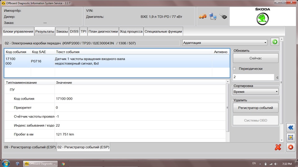
Полный размер
Ошибка 1 в памяти неисправностей
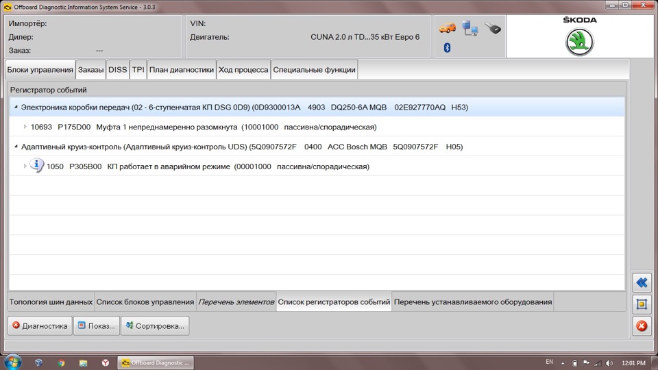
Полный размер
Ошибка 2 в памяти неисправностей
Если мы встретим ошибки, конечно же нам это облегчит задачу, но как правило они отсутствуют и тогда — только проверка блоков измерительных величин, TPI, и т.д.
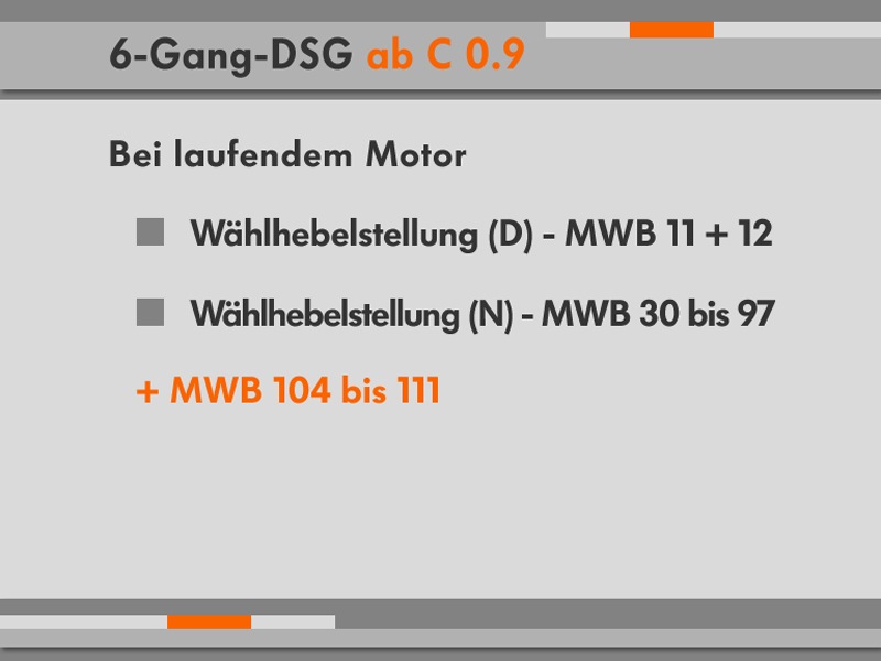
Блоки измерительных величин, необходимых для анализа
По сравнению с DQ200, блоков измерительных величин для DQ250 гораздо меньше. C одной стороны — это лучше, так как нет необходимости тратить много времени, изучая каждый показатель. Но с другой стороны — меньшее количество данных ограничивает возможность понимания всех процессов, которые происходят при работе. Но, как говорится «Что есть — тем и пользуемся».
Для диагностики DQ250 придется использовать режим «Самодиагностика», так как режим «Ведомый Поиск Неисправностей/Функции» имеет только несколько полезных на мой взгляд «подсказок», которые нам предоставляет диагностическое оборудование.
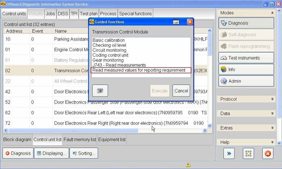
Полный размер
Одна из самых полезных функций — Считывание данных для уведомления
В функции «Считывание данных для уведомления» — все параметры, которых по мнению производителя достаточно для анализа, фиксируются при неподвижном автомобиле и сохраняются в протоколе диагностики. Без этих данных производитель не рассматривает ни один технический запрос.
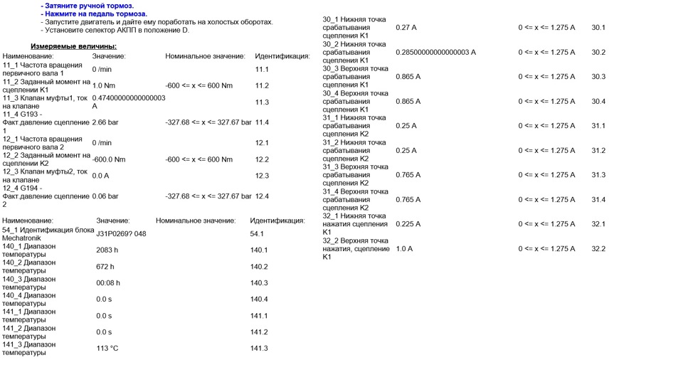
Полный размер
Данные, сохраненные в протоколе диагностики
Это занимает, некоторое время, да и сохранение блоков величин осуществляется на неподвижном автомобиле.
В случае испытательной поездки (например, для проверки работы сцепления) придется использовать режим «Самодиагностика» и самостоятельно выбирать требуемые блоки измерительных величин.
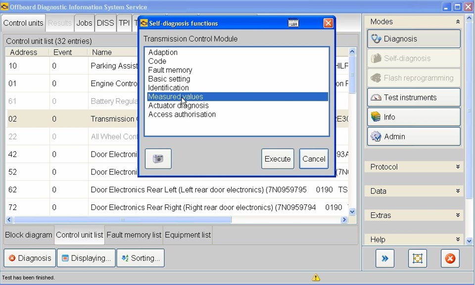
Полный размер
Выбор отображения измеряемых величин в режиме
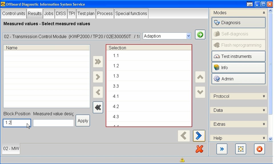
Полный размер
Выбор необходимых групп измеряемых величин
Но в отличии от DQ200 — описания каналов и обозначения параметров практически нет.
Именно по этой причине, я и решил поделиться с Вами накопленной годами информацией, в том числе и информацией из TPI.
В первую очередь, необходимо определить идентификационные данные Mechatronik в блоках измерительных величин 54.1, 41.1 (обозначение ПО — аналогично DQ200).
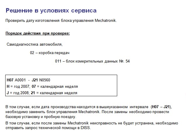
Информация от производителя
Если окажется, что дата изготовления Mechatronik в указанном диапазоне H07 – J21, то его необходимо заменить. Причиной является — внутренний дефект Mechatronik.
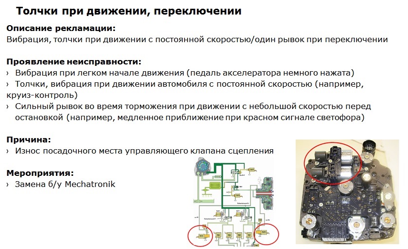
Неисправность Mecahtronik
Аналогично и с ПО — определив идентификацию и при наличии более актуального ПО, необходимо его обновить.
Источник: www.drive2.ru
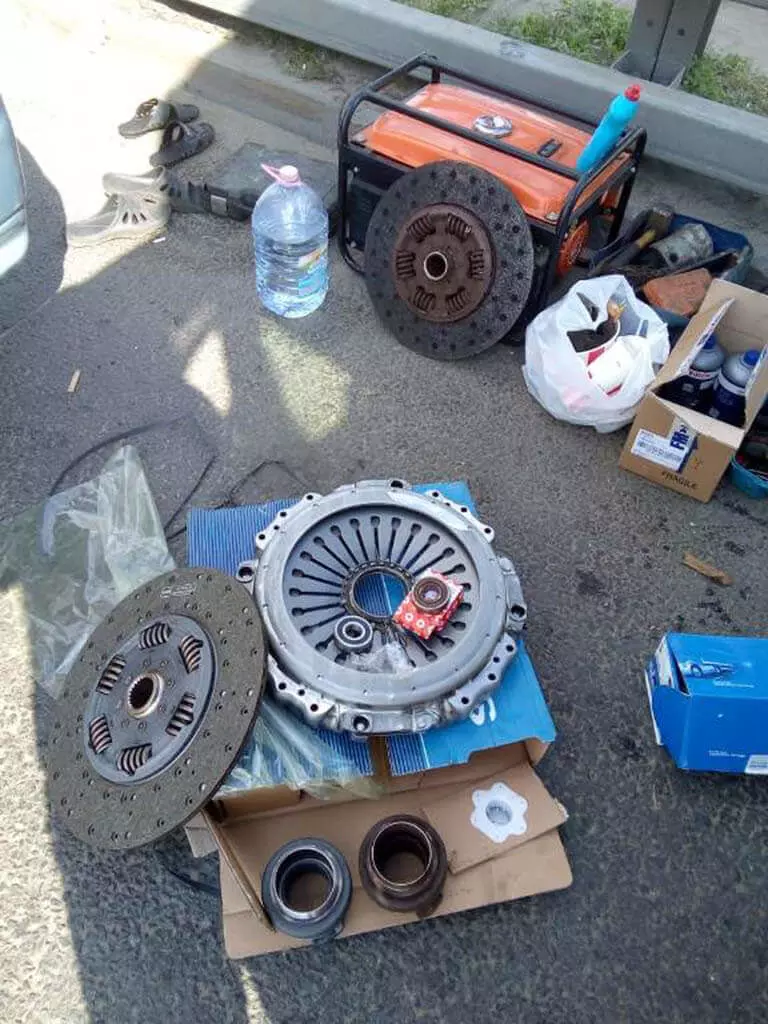
Вызывайте службу «Техпомощи 24 Вольта», если заглох и не заводится экскаватор JCB. Быстро приедем, найдем и устраним причину неисправностей с выездом к клиенту по Москве и Московской области. Покупаем, привозим нужные запчасти, гарантируем оперативный, профессиональный, недорогой ремонт.
Работа Стоимость
| Заглох и не заводится JCB: выезд и диагностика | 8000 руб. |
| Выезд за Москву | 50 руб/км |
Проведём диагностику прямо на месте поломки! Звоните!
8-999-999-90-24
Почему заглох и не заводится экскаватор JCB
Стартер крутит, двигатель не запускается или остается без движения при повороте ключа в замке зажигания.
Проблемы тут бывают 3 типов:
- механические;
- аппаратные – сбои в работе электроники;
- сбои в работе электрооборудования.
Для точного определения причины, почему заглох и не заводится JCB, необходима компьютерная диагностика. Путем визуального осмотра найти поломку не получится, так как техника управляется электроникой и только сканирование ее рабочих параметров точно покажет проблемный участок.
Когда трактор JCB заглох и не заводится, на приборной панели загорается сообщение об ошибке или Check Engine, отображается код ошибки. Правильно и быстро она расшифровывается с помощью сканера. Но бывает, что двигатель не запускается, а сигнал не загорается. Для экономии времени, точного определения причины неисправности, вызывайте службу «Техпомощи 24Вольта».

Почему двигатель не запускается, а стартер крутит
В этом случае проблема кроется в плоскости механики или электрооборудования. Причины того, что JCB 3CX не заводится, бывают следующими:
- сбои в работе иммобилайзера, поломка чипа в ключе;
- завоздушивание топливной системы;
- выход из строя форсунок;поломка обратного клапана;
- проблемы с топливным насосом – ТНВД.
Самостоятельный поиск, устранение перечисленных поломок без опыта, специального оборудования связано с длительным простоем техники. Поэтому, если заглох и не заводится трактор JCB, экономьте время, вызывайте службу «Техпомощи 24 Вольта».
Когда двигатель не запускается и стартер не крутит
Тут проблемы кроются в электронике или электрике. Наиболее распространенные причины того, что заглох и не заводится Джисиби 3CX:
- замыкание проводки;
- обрыв шины CAN;
- поломка замка зажигания;
- выход из строя реле стартера;
- поломка электронного блока управления – ЭБУ.
Помните, многократные попытки запустить двигатель приводят к ускоренному износу стартера. Также к сокращению эксплуатационного ресурса приводит низкое напряжение, его перепады. Наши мастера оперативно найдут, профессионально устранят проблемы, предупредят серьезные поломки.

Профессиональная диагностика двигателя
Работы по устранения поломок, когда заглох и не заводится трактор JCB, начинаются с диагностики. Она проводится с использованием дилерских сканеров, путем визуального осмотра. В работе используем профессиональное оборудование, инструмент, практический опыт устранения различных типов неисправностей.
Звоните в службу «Техпомощь 24 Вольта», если JCB заглох и не заводится. Оперативно, профессионально проведем диагностику, устраним проблемы с электрикой, электроникой, механические поломки, сэкономим время, технический, эксплуатационный ресурс техники.
Источник: remont-gruzovyh.ru

![]()
JCB 3CX_4CX_214_214e_215_217 PDF Service
Adobe Acrobat Document
37.4 MB
![]()
JCB Fastrac Service Manual PDF.pdf
Adobe Acrobat Document
544.8 KB
![]()
JCB 3CX_4CX Wiring Diagrams.pdf
Adobe Acrobat Document
10.7 MB
JCB Common Rail Fuel Codes
The electronic engine control unit (ECU) and devices connected to it are distinguished by their robust construction and are basically more reliable than connecting wires and
connectors.
BEFORE checking or replacing electrical devices, make sure that the appropriate wires and connectors are installed and that they are functioning properly. In many cases, electrical faults are
easily fixed by identifying faulty wires,
connectors or ground points. Before performing work, it is necessary to disconnect the electrical system by disconnecting the battery. Check the relevant machine documentation for the correct
procedure.
1 ELECTRICAL WIRING HARNESS — Visually inspect the connecting wires and connectors for signs of damage.
Check out the following aspects:
a Shabby wires — periodic short circuits.
b Cut wires — open circuits. A likely cause is the ingress of wires into the mechanical mechanisms of the machine.
c Broken wires — open circuits. The probable cause is incorrect laying or linking of wires without enough slack for the machine to move.
d Flamed wires — periodic short circuits. A likely cause is contact with the turbocharger or exhaust system.
2 CONNECTORS — Visually inspect the corresponding connectors. Check out the following aspects:
a Connection — Periodic short circuits. Make sure that the connectors are correctly connected and that their locking mechanisms are locked.
b Damage — intermittent open circuit or short circuit. Inspect the connectors for signs of physical damage (such as broken housings or retainer clips). Upon contact with a hot exhaust system or
turbocharger, the connectors may also melt. Disconnect the connectors and inspect the pin contacts for damage (e.g., corroded, bent, or broken pin contacts). DO NOT TOUCH the pin contacts of the
connector on the electronic engine control unit (ECU). Broken connectors must be replaced.
c Pollution — intermittent open circuit or short circuit. Disconnect the connectors and inspect their interior for contamination (usually water, oil, or hydraulic fluid). If necessary, clean the
pin pins of the connector and the socket with a cotton swab or similar object. DO NOT TOUCH the pin contacts of the connector on the electronic engine control unit (ECU). If there are clear signs
of water contamination, the connectors must be allowed to dry completely before connecting. Carefully inspect all sealing elements for signs of contamination or damage.
3 Ground Points — Locate the ground points on the engine and machine. Make sure the wire terminals are connected correctly.
Fault Codes — Structure
The structure of the DTCs, also known as Diagnostic Trouble Codes (DTCs), has been standardized and represented by a 7-digit code for all road and off-road vehicles and vehicles. According to the
standard (called J2012), all DTCs must follow the structure below.
1st character — defines the vehicle system (e.g. P = power train, C = chassis, U = network)
2nd and 3rd characters — define the subsystem (transmission, CAN network, brakes, etc.)
4th and 5th symbols — identify a specific component, circuit or fault (e.g. starter relay)
6th and 7th characters — are called “fault type bytes” (FTB) and indicate a specific fault (for example, 11 = short circuit to ground). For a complete listing, see FTB Numbers below.
Some special fault codes are defined by an international standard, while others can be determined by individual vehicle manufacturers.
Depending on the specification of the machine, there are several ways to access and display fault codes that are recorded by the engine ECU:
CAN Bus Display
The machine can be equipped with a CAN-bus based display. Such a display may show all registered codes, for example, P0047. All registered codes will be displayed. The operator may be able to
erase the fault code log. For more information, see the relevant machine documentation.
Computer connected to CAN bus
Access to the registered error codes can be provided using a suitable laptop on which the appropriate diagnostic software is installed, for example, the engine diagnostic tool JCB 444 Engine
Diagnostics. The computer must be connected to the machine’s CAN bus socket using a data transfer adapter (DLA).
After connecting, all registered codes can be displayed. The engineer also has the opportunity to erase the fault code log.
Fault Byte Number (FTB) Numbers
- 00 No subtype information
- 02 General fault with signal
- 04 Internal system fault (ECU)
- 07 Mechanical failure
- 05 System programming failure
- 09 Component malfunction
- 11 Short to ground (SC2G)
- 12 Battery short circuit (SC2VBAT)
- 13 Open circuit (OS)
- 16 Circuit voltage below acceptable threshold
- 17 Circuit voltage above acceptable threshold
- 18 Circuit current below acceptable threshold
- 19 Circuit current above acceptable threshold
- 1A Circuit Resistance Above Threshold
- 1B Circuit resistance below acceptable threshold
- 1C Circuit voltage out of range
- 1F Intermittent circuit
- 23 Constantly low signal
- 24 Constantly high signal
- 26 Rate of change of signal below acceptable threshold value
- 27 The rate of change of the signal is above an acceptable threshold value
- 29 Invalid signal
- 2F Volatile Signal
- 31 No signal (skipped / missing)
- 36 Signal frequency too low
- 37 Signal frequency too high
- 38 Wrong signal frequency
- 45 Program memory failure
- 46 Calibration / parameter memory failure
- 47 Malfunction of self-monitoring system / microcontroller / microprocessor
- 4B temperature rise
- 54 No calibration
- 64 Malfunction of signal acceptability
- 62 Signal comparison failure
- 72 Actuator stuck open
- 73 Actuator stuck closed
- 71 Actuator stuck
- 81 Received network data contains error
- 85 Signal out of range
- 86 Invalid CAN signal
- 88 BUS OFF
- 9A Operating conditions for a component or system
- 92 Performance or malfunction
- 96 Component malfunction or internal malfunction
- 97 Component or system is obstructed or blocked
- 98 Temperature rise of a component or system
If a malfunction is detected, the computer determines the severity of the malfunction and can take measures to protect the engine or machine from potential damage.
An ECU can take one of four of the following actions:
Inaction
The computer has decided that there is no direct risk to the engine or machine and that the engine is operating normally. Nevertheless, measures should be taken to rectify the malfunction as soon
as possible.
Low Torque Mode:
The engine output is reduced in order to reduce the voltage and temperature of the engine, and to minimize its damage. Machines should be stopped at the earliest opportunity to prevent further
damage.
Emergency mode of movement to the place of repair work:
Engine output is limited and engine speed is reduced to reduce engine voltage and temperature, and to minimize damage to the engine. Stop the machine as soon as possible to prevent further
damage.
Engine muffling / delayed engine muffling
The engine control unit automatically shuts off the engine to prevent an impending failure.
Fault Codes — Numeric List
• Click on the DTC to go to the specific device information and troubleshooting procedure.
P0001 The control circuit of the fuel volume regulator is open
P0002 Range / Performance of the fuel volume regulator control circuit
P0003 Low signal of the control circuit of the fuel volume regulator
P0004 High signal volume control circuit of the fuel volume regulator
P0016 Relationship between the position of the crankshaft and the position of the camshaft
P0087 Too low pressure in the fuel line / system
P0088 Too high pressure in the fuel line / system
P0089 Fuel Pressure Regulator 1 Performance
P0090 The control circuit of the fuel pressure regulator 1 is open
P0091 Low signal control circuit of the fuel pressure regulator 1
P0092 High signal of the control circuit of the fuel pressure regulator 1
P0095 Intake Air Temperature Sensor 2 Circuit
P0096 Intake Air Temperature Sensor 2 Range / Performance
P0097 Low signal circuit intake air temperature sensor 2
P0098 High Intake Air Temperature Sensor 2 Circuit
P0099 Intermittent / erratic intake air temperature sensor 2 circuit
P0105 Manifold Absolute Pressure / Barometric Pressure Circuit
P0106 Range / Performance of the manifold absolute pressure / barometric pressure circuit
P0110 Intake Air Temperature Sensor 1 Circuit
P0111 Low signal circuit intake air temperature sensor 1
P0124 High signal circuit intake air temperature sensor 1
P0113 High signal circuit intake air temperature sensor 1
P0115 Circuit 1, engine coolant temperature sensor
P0116 Range / Performance of circuit 1 of the coolant temperature sensor
engine
P0117 Low signal circuit 1 of the engine coolant temperature sensor
P0118 High signal circuit 1 temperature sensor engine coolant
P0120 Throttle / Pedal Position Sensor / Switch A Circuit
P0121 Range / Performance of “A” Sensor / Throttle / Pedal Position Switch
P0180 Circuit «A» fuel temperature sensor
P0181 Range / Performance of the fuel temperature sensor circuit «A»
P0182 Low signal circuit A «fuel temperature sensor
P0183 High signal circuit «A» fuel temperature sensor
P0190 Circuit «A» of the fuel pressure sensor in the highway
P0191 Range / Performance of circuit “A” of the fuel pressure sensor in the line
P0192 Low signal circuit «A» of the fuel pressure sensor in the highway
P0193 High signal circuit «A» of the fuel pressure sensor in the highway
P0194 Intermittent / unstable signal of the circuit «A» of the fuel pressure sensor in the highway
P0200 Injector circuit open
P0201 Injector circuit open — 1st cylinder
P0202 Injector circuit open — 2nd cylinder
P0203 Injector circuit open — 3rd cylinder
P0204 Injector circuit open — 4th cylinder
P0205 Injector circuit open — 5th cylinder
P0206 Injector circuit open — 6th cylinder
P0218 Transmission Fluid Over Temperature
P0220 Circuit «B» of the sensor / switch throttle / pedal position
P0236 Range / Performance of circuit “A” of turbocharger / supercharger boost sensor
P0252 Range / Performance «A» of the fuel pump fuel meter (cam / rotor / injector)
P0253 Low signal “A” of the fuel metering device of the high pressure fuel pump
(camshaft / rotor / injector)
P0254 High signal «A» fuel metering pump fuel (cam / rotor / injector)
P0261 Low signal of the injector circuit of the 1st cylinder
P0262 High signal injector circuit 1 cylinder
P0263 Deposit / balancing of the 1st cylinder
P0264 Low signal of the injector circuit of the 2nd cylinder
P0265 High signal circuit injector 2nd cylinder
P0266 contribution / balancing of the 2nd cylinder
P0267 Low signal of the injector circuit of the 3rd cylinder
P0268 High signal circuit injector 3rd cylinder
P0269 Contribution / balancing of the 3rd cylinder
P0270 Injector 4 Low Signal
P0271 High signal injector circuit 4th cylinder
P0272 Deposit / balancing of the 4th cylinder
P0273 Low signal of the injector circuit of the 5th cylinder
P0274 High signal injector circuit 5th cylinder
P0275 Contribution / balancing of the 6th cylinder
P0276 Low signal of the injector circuit of the 6th cylinder
P0277 High signal circuit injector 6th cylinder
P0278 Contribution / balancing of the 6th cylinder
P029A The balancing of the 1st cylinder by fuel production is at the maximum limit
meaning
P029B The balancing of the 1st cylinder by fuel production is at the minimum limit
meaning
P029E The balancing of the 2nd cylinder by fuel production is at the maximum limit
meaning
P029F The balancing of the 2nd cylinder by fuel production is at the minimum limit
meaning
P02A2 The balancing of the 3rd cylinder by fuel production is at the maximum limit
meaning
P02A3 The balancing of the 3rd cylinder by fuel production is at the minimum limit
meaning
P02A6 Balancing of the 4th cylinder by fuel production is at the maximum limit
meaning
P02A7 Balancing of the 4th cylinder with fuel production is at the minimum limit
meaning
P02A8 Balancing of the 5th cylinder by fuel production is at the maximum limit
meaning
P02A9 Balancing of the 5th cylinder by fuel production is at the minimum limit
meaning
P02A10 The balancing of the 6th cylinder by fuel production is at the maximum limit
meaning
P02A11 The balancing of the 6th cylinder by fuel production is at the minimum limit
meaning
P02EE Range 1 / Injector Circuit Performance
P02EF Range / Performance of the Injector Chain of the 2nd Cylinder
P02F0 Range / Performance of the injector circuit of the 3rd cylinder
P02F1 Range / Performance 4 Injector Circuit
P02F2 Range / Performance 5th Injector Circuit
P02F3 Range / Performance 6th Injector Circuit
P0335 Circuit «A» crankshaft position sensor
P0340 Circuit «A» camshaft position sensor
P0341 Range / Performance of the camshaft position sensor circuit «A»
P0371 Excessive number of pulses «A» signal high-resolution time stamps
P0372 Too low number of pulses «A» signal high-resolution time stamps
P0374 No pulse «A» signal high-resolution time stamps
P0500 «A» vehicle speed sensor
P0501 Range / Performance «A» of the vehicle speed sensor
P0503 Intermittent / unstable / high signal «A» of the vehicle speed sensor
P0520 Low oil pressure warning light control circuit
P0521 Range / Performance of the engine oil pressure sensor / switch
P0522 High oil pressure
P0523 Low oil pressure
P0560 System Voltage
P0562 System Low Voltage
P0563 System High Voltage
P0566 Signal «off» («Off») cruise control
P0567 Cruise Control Resume Signal
P0569 Cruise control “Coast” signal
P0570 Cruise Control Accelerate Signal
P0575 Cruise Control Input Circuit
P0602 Control Module Programming Error
P0603 Standby memory error (CAM) of the internal control module
P0604 RAM error (RAM) of the internal control module
P0605 Read-only memory error (ROM) of the internal control module
P0606 Functional malfunction of the security system
P0607 Functional malfunction of the security system
P060A Functional Security Malfunction
P060B Functional malfunction of the security system
P0612 Control circuit of the engine speed relay
P0615 Starter Relay Circuit
P0616 Starter Relay Circuit Low
P0617 Starter Relay Circuit High
P061B Functional malfunction of the security system
P061C Functional malfunction of the security system
P061E Functional malfunction of the security system
P0627 Global Fuel Pump Malfunction — Open Circuit
P0628 Global fuel pump malfunction — short to ground
P0629 Global fuel pump malfunction — short to battery
P062B Functional malfunction of the security system
P062D Fuel Injector Control Circuit Performance
P062E Fuel Injector Control Performance
P062F EEPROM error of the internal control module
P0630 VIN code not programmed or incompatible — ECM / PCM
P0641 Circuit «A» of the reference voltage of the sensor is open
P0650 Malfunction Indicator Light (MIL) Control Circuit
P0651 Circuit «B» of the reference voltage of the sensor is open
P0655 Malfunction of the engine test indicator light (CEL)
P0656 output circuit of the fuel level sensor
P0668 PCM / ECM / TCM Internal Temperature Sensor Circuit A Low
P0669 High signal circuit «A» internal temperature sensor PCM / ECM / TCM
P0685 ECM / PCM power relay control circuit open
P0697 Circuit «C» of the reference voltage of the sensor is open
P1101 Positive malfunction of a pressure control error in the line
P1102 Negative malfunction of a pressure control error in the line
P1103 Malfunction of pressure in the line
P1104 Injector Update Failure
P1105 Injector Update Failure
P1106 Injector Update Failure
P1107 Injector Update Failure
P1108 Injector Update Failure
P1109 Injector Update Failure
P110A Injector Update Failure
P110B Injector Update Failure
P1500 Faulty foot choke / pedal — emergency mode of movement to the place of repair work
P1501 Foot Choke / Pedal Failure — Low Torque
P1503 Faulty hand throttle — emergency mode of movement to the venue
repair work
P1504 Manual Throttle Malfunction — Low Torque
P1506 Global Throttle / Pedal Failure — Emergency Travel Mode
repair work
P1509 CAN bus communication error with TSC
P1602 Global Starter Relay Control Circuit
P1603 Functional malfunction of the security system
P1604 Functional malfunction of the security system
P1605 Functional malfunction of the security system
P1606 Functional malfunction of the security system
P2120 Fault channel 1 signal hand pedal
P2125 Malfunction of channel 2 of a signal of a manual pedal
P2135 «A» / «B» Voltage Matching of Throttle / Pedal Position Sensor / Switch
P2138 Hand pedal signal mapping failure
P2147 Malfunction (cutoff) of the injector voltage source
P2148 Malfunction (cutoff) of the injector voltage source
P2226 Chain «A» of the barometric pressure sensor
P2228 Low signal circuit «A» barometric pressure sensor
P2229 High signal circuit «A» barometric pressure sensor
P2264 Sensor circuit for water in the fuel
P2265 Range / Performance of the fuel water sensor circuit
P2266 Low fuel water sensor circuit signal
P2267 High fuel water sensor circuit signal
P2269 State of water in the fuel
P250B Range / Performance Engine Oil Level Sensor Circuit
P256A Idling Sensor / Switch Circuit
open
P256B Range / Performance Sensor / Switch Selector Speed
engine idling
P256C Engine Idle Selector Sensor / Switch Low
P256D High Idle Sensor / Selector Speed Sensor Signal
U0001 High speed CAN data bus
U0073 Bus A of the control module data transmission is off
U0100 Communication failure with ECM / PCM «A»
U0121 Lost Communication With Anti-Lock Brake System (ABS) Control Module
U0401 Invalid data received from ECM / PCM «A»
U3FFF DTC SAE does not exist — specific manufacturer data required
Home » JCB » JCB JS-Excavator’s Fault Codes List
See also:
- JCB Service Repair Manuals PDF
- JCB flash codes list

JCB JS330
| Error Codes | Error String | Description |
| 101 | CRANK | A crank signal was not detected by the ECU1. |
| 102 | FUEL | The fuel sensor is open-circuit |
| 103 | EN TMP | The engine temperature sensor is open-circuited. |
| 104 | HYD TMP | The hydraulic temperature sensor is open-circuited. |
| 105 | SET PT | The throttle set potentiometer is open-circuited. |
| 106 | SENS PT | The throttle sense potentiometer is open-circuited. |
| 107 | OIL SW | The oil pressure switch is reporting oil pressure is present when the engine is not running. |
| 108 | FLYWHEEL | The flywheel sensor is reporting an engine speed even though the engine is not running. |
| 109 | ALT | The alternator is reporting a voltage even when the engine is not running. |
| 110 | THR SOL | The throttle solenoid is open-circuited. This can only be detected when the engine is not running. |
| 111 | BOOM SP | The boom lower speed regulation output is open-circuited. |
| 113 | MAX FLW | The max flow solenoid is open-circuited. For JS200W machines, this error can only be detected when the
engine is not running due to the fact that this is a proportional valve on these machines. |
| 115 | BOOM | The boom priority solenoid is open-circuited. |
| 116 | FL PMP | The refuel pump output is open-circuited. |
| 117 | HORN | The horn output is open-circuited. |
| 118 | HYD PMP | The hydraulic pump is open-circuited. Because this is a proportional valve, this error can only be detected
when the engine is not running. |
| 119 | SLW LCK | The slew lock solenoid is open-circuited. |
| 120 | HYD FAN | The hydraulic fan output is open-circuited. This can only be detected when the engine is not running. |
| 121 | SLW BRK | The slew brake solenoid is open-circuited. |
| 122 | SLW ST | The slew shut off solenoid is open-circuited. |
| 127 | TL CHNG | The travel change solenoid is open-circuited. |
| 128 | WASHER | The washer motor is open-circuited. |
| 129 | DOZER | The dozer solenoid is open-circuited. |
| 130 | GRB CW | The grab/rotate clockwise solenoid is open-circuited. |
| 131 | GRB CCW | The grab/rotate counter-clockwise solenoid is open-circuited. |
| 132 | LW FLOW | The low flow solenoid is open-circuited. |
| 133 | ISOL | The hydraulic isolator solenoid is open-circuited. |
| 135 | 2 STAGE | The 2nd stage relief solenoid is open-circuited. |
| 136 | QK HTCH | The quick hitch solenoid is open-circuited. |
| 138 | HAMMER | The hammer solenoid is open-circuited. |
| 139 | CUSHION | The hard/soft cushion solenoid is open-circuited. |
| 142 | ENG SD | The engine shutdown output is open-circuited. |
| 143 | GLW PLG | The glow plugs output is open-circuited. |
| 156 | TL FLW3 | The travel flow 3 solenoid is open-circuited. |
| 157 | TL FLW2 | The travel flow 2 solenoid is open-circuited. |
| 158 | GR CHNG | The M2 or gear change solenoid is open-circuited. |
| 159 | BRKE LT | The brake light output is open-circuited. |
| 160 | AXLE LK | The axle lock solenoid is open-circuited. |
| 161 | STAB UP | The stabilizer up (Rear Right on Auto’s) solenoid is open-circuited. |
| 162 | STAB DN | The stabilizer down (Front Left / Front Dozer on Auto’s) solenoid is open-circuited. |
| 163 | STAB LH | The stabilizer left (Rear Left / Rear Dozer on Auto’s) solenoid is open-circuited. |
| 164 | STAB RH | The stabilizer right (Front Right on Auto’s) solenoid is open-circuited. |
| 165 | CRUISE | The cruise control solenoid is open-circuited. |
| 166 | DIG ISL | The dig end isolation solenoid is open-circuited. |
| 167 | PRK BK | The M1 or park brake solenoid is open-circuited. |
| 168 | DRV ISL | The drive isolate solenoid is open-circuited. |
| 202 | FUEL | The fuel level sensor is short-circuited. |
| 203 | EN TMP | The engine temperature sensor is short-circuited. |
| 204 | HYD TMP | The hydraulic temperature sensor is short-circuited. |
| 205 | SET PT | The throttle set potentiometer is short-circuited. |
| 206 | SENS PT | The throttle sense potentiometer is short-circuited. |
| 210 | THR SOL | The throttle solenoid is short-circuited. This can only be detected when the engine is not running. |
| 211 | BOOM SP | The boom lower speed regulation output is short-circuited. |
| 212 | INT LT | The interior light is short-circuited. |
| 213 | MAX FLW | The max flow solenoid is short-circuited. For JS200W machines, this error can only be detected when the
engine is not running due to the fact that this is a proportional valve on these machines. |
| 214 | BEACON | The beacon output is short-circuited. |
| 215 | BOOM PR | The boom priority solenoid is short-circuited. |
| 216 | FL PMP | The refuel pump solenoid is short-circuited. |
| 217 | HORN | The horn output is short-circuited. |
| 218 | HYD PMP | The hydraulic pump is short-circuited. Because this is a proportional valve, this error can only be detected
when the engine is not running. |
| 219 | SLW LCK | The slew lock solenoid is short-circuited. |
| 220 | HYD FAN | The hydraulic fan solenoid is short-circuited. The fault can only be detected when the engine is not running. |
| 221 | SLW BRK | The slew brake solenoid is short-circuited. |
| 222 | SLW ST | The slew shut off solenoid is short-circuited. |
| 223 | LW WIPR | The lower wiper motor is short-circuited. |
| 224 | WIPER | The wiper motor is short-circuited. |
| 225 | LH CAB LT | The boom work light is short-circuited. |
| 226 | RH CAB LT | The toolbox work light is short-circuited. |
| 227 | TL CHNG | The travel change solenoid is short-circuited. |
| 228 | WASHER | The washer motor is short-circuited. |
| 229 | DOZER | The dozer solenoid is short-circuited. |
| 230 | GRB CW | The grab/rotate clockwise solenoid is short-circuited. |
| 231 | GRB CCW | The grab/rotate counter-clockwise solenoid is short-circuited. |
| 232 | LW FLOW | The low flow solenoid is short-circuited. |
| 233 | ISOL | The isolator solenoid is short-circuited. |
| 234 | EMG STP | The emergency stop solenoid is short-circuited. |
| 235 | 2 STAGE | The 2nd stage relief solenoid is short-circuited. |
| 236 | QK HTCH | The quick hitch solenoid is short-circuited. |
| 237 | TL ALRM | The travel alarm output is short-circuited. |
| 238 | HAMMER | The hammer solenoid is short-circuited. |
| 239 | CUSHION | The hard/soft cushion solenoid is short-circuited. |
| 240 | BOOM LT | The boom work light is short-circuited. |
| 241 | TLBX LT | The toolbox work light is short-circuited. |
| 242 | ENG SD | The engine shutdown solenoid is short-circuited. |
| 243 | GLW PLG | The glow plugs are short-circuited. |
| 244 | CNT LT | The counter-weight work light is short-circuited. |
| 245 | LH IND | The LH turn indicator is short-circuited. |
| 246 | LH SIDE | The LH sidelight is short-circuited. |
| 247 | LH FOG | The LH fog light is short-circuited. |
| 248 | LH MAIN | The LH main beam is short-circuited. |
| 249 | LH DIP | The LH dip beam is short-circuited. |
| 250 | RH IND | The RH turn indicator is short-circuited. |
| 251 | RH SIDE | The RH sidelight is short-circuited. |
| 252 | RH FOG | The RH fog light is short-circuited |
| 253 | RH MAIN | The RH main beam is short-circuited. |
| 254 | RH DIP | The RH dip beam is short-circuited. |
| 255 | HZD LED | The hazard LED is short-circuited. |
| 256 | TL FLW3 | The travel flow 3 solenoid is short-circuited. |
| 257 | TL FLW2 | The travel flow 2 solenoid is short-circuited. |
| 258 | GR CHNG | The M2 or gear change solenoid is short-circuited. |
| 259 | BRKE LT | The brake light output is short-circuited. |
| 260 | AXLE LK | The axle lock solenoid is short-circuited. |
| 261 | STAB UP | The stabilizer up solenoid is short-circuited. |
| 262 | STAB DN | The stabilizer down solenoid is short-circuited. |
| 263 | STAB LH | The stabilizer left solenoid is short-circuited. |
| 264 | STAB RH | The stabilizer right solenoid is short-circuited. |
| 265 | CRUISE | The cruise control solenoid is short-circuited. |
| 266 | DIG ISL | The dig end isolate solenoid is short-circuited. |
| 267 | PRK BK | The M1 or park brake solenoid is short-circuited. |
| 268 | DRV ISL | The drive isolate solenoid is short-circuited. |
| 300 | EC1 CAN | The ECU1 module is no longer communicating on the CAN bus. |
| 301 | ECW CAN | The ECUW module is no longer communicating on the CAN bus. |
| 302 | THRT CAL | The difference between the minimum and maximum calibration points for the throttle dial pot is less than 100
A/D points. |
| 303 | THRT CAL | The difference between the minimum and maximum calibration points for the throttle sense pot is less than
100 A/D points. This error does not exist on machines fitted with an EEC. |
| 304 | THRT CAL | The throttle dial pot is greater than 10% but the engine is still running at the idle position. This condition must
exist for at least 15 seconds before it is reported. This error does not exist on machines fitted with an EEC. |
| 305 | THRT CAL | The error term of the PID algorithm is greater than 20 A/D points for more than 20 consecutive seconds. |
- Коды ошибок спецтехники JCB
- Коды ошибок двигателя JCB (Isuzu 4HK, 6HK)
- Истории из практики ремонта JCB
При возникновении неисправности на технике, информационный дисплей EMS сразу отображает на экране ошибки, при этом зуммер (сигнализатор) начинает пищать. Для отключения зуммера нужно нажать на кнопку ACK на мониторе JCB.
Подробное описание ошибок электронных блоков управления гидравлики ECU1 728/29900 728/35700 728/29900 728/35700 и блока электроники ECUW 728/35800 728/18500 728/15500 JCB.
| Коды ошибок |
Надпись на дисплее монитора | Описание неисправности |
| 101 | CRANK | ЭБУ1 не обнаруживает сигнал от коленвала. |
| 102 | FUEL | Цепь датчика топлива разомкнута |
| 103 | EN TMP | Цепь датчика температуры двигателя разомкнута. |
| 104 | HYD TMP | Цепь датчика температуры гидравлической жидкости разомкнута. |
| 105 | SET PT | Цепь потенциометра заданного положения дроссельной заслонки разомкнута. |
| 106 | SENS PT | Цепь потенциометра фактического положения дроссельной заслонки разомкнута. |
| 107 | OIL SW | Датчик давления масла выдает сигнал наличия давления при отключенном двигателе. |
| 108 | FLYWHEEL | Датчик карданной передачи выдает сигнал оборотов двигателя при отключенном |
| 109 | ALT | Генератор выдает сигнал наличия напряжения при отключенном двигателе. |
| 110 | THR SOL | Цепь электромагнитного клапана дроссельной заслонки разомкнута. Обнаруживается только при отключенном двигателе. |
| 111 | BOOM SP | Цепь регулирования малой скорости стрелы разомкнута. |
| 113 | MAX FLW | Цепь электромагнитного клапана максимального расхода разомкнута. Для машин JS200W данная ошибка может быть обнаружена тольк |
| 115 | BOOM | Цепь электромагнитного клапана приоритета разомкнута |
| 116 | FL PMP | Цепь выходного контура насоса дозаправки разомкнута. |
| 117 | HORN | Цепь выходного контура клаксона разомкнута. |
| 118 | HYD PMP | Цепь гидравлического насоса разомкнута. Поскольку клапан является пропорциональным, ошибка обнаруживается только при отключенном двигателе |
| 119 | SLW LCK | Цепь электромагнитного клапана блокиратора стрелы разомкнута. |
| 120 | HYD FAN | Цепь выходного контура вентилятора гидросистемы разомкнута. Обнаруживается только при отключенном двигателе |
| 121 | SLW BRK | Цепь электромагнитного клапана разблокировки стрелы разомкнута |
| 122 | SLW ST | Цепь электромагнитного клапана отключения стрелы разомкнута. |
| 127 | TL CHNG | Цепь электромагнитного клапана переключения скорости движения разомкнута. |
| 128 | WASHER | Цепь двигателя омывателя разомкнута. |
| 129 | DOZER | Цепь электромагнитного клапана отвала разомкнута. |
| 130 | GRB CW | Цепь электромагнитного клапана вращения грейфера по часовой стрелке разомкнута. |
| 131 | GRB CCW | Цепь электромагнитного клапана вращения грейфера против часовой стрелки разомкнута. |
| 132 | LW FLOW | Цепь электромагнитного клапана низкого расхода разомкнута. |
| 133 | ISOL | Цепь электромагнитного клапана гидроизолятора разомкнута. |
| 135 | 2 STAGE | Цепь предохранительного электромагнитного клапана ступени 2 разомкнута. |
| 136 | QK HTCH | Цепь электромагнитного клапана быстрой сцепки разомкнута. |
| 138 | HAMMER | Цепь электромагнитного клапана молота разомкнута. |
| 139 | CUSHION | Цепь электромагнитного клапана твердой/мягкой подушки разомкнута. |
| 142 | ENG SD | Цепь выходного контура отключения двигателя разомкнута. |
| 143 | GLW PLG | Цепь выходного контура свечей накаливания разомкнута. |
| 156 | TL FLW3 | Цепь электромагнитного клапана расхода 3 движения разомкнута. |
| 157 | TL FLW2 | Цепь электромагнитного клапана расхода 2 движения разомкнута. |
| 158 | GR CHNG | Цепь электромагнитного клапана М2 или переключения передач разомкнута. |
| 159 | BRKE LT | Цепь выходного контура лампы тормоза разомкнута. |
| 160 | AXLE LK | Цепь электромагнитного клапана блокировки моста разомкнута. |
| 161 | STAB UP | Цепь электромагнитного клапана подъема стабилизатора разомкнута. |
| 162 | STAB DIN | Цепь электромагнитного клапана опускания стабилизатора разомкнута. |
| 163 | STAB LH | Цепь электромагнитного клапана левого стабилизатора разомкнута. |
| 164 | STAB RH | Цепь электромагнитного клапана правого стабилизатора разомкнута. |
| 165 | CRUISE | Цепь электромагнитного клапана круиз-контроля разомкнута. |
| 166 | DIG ISL | Цепь электромагнитного клапана изолятора режущей кромки разомкнута. |
| 167 | PRK BK | Цепь электромагнитного клапана М1 или стояночного тормоза разомкнута. |
| 168 | DRV ISL | Цепь электромагнитного клапана изолятора привода разомкнута. |
| 202 | FUEL | Короткое замыкание цепи датчика уровня топлива. |
| 203 | EN TMP | Короткое замыкание цепи датчика температуры двигателя. |
| 204 | HYD TMP | Короткое замыкание цепи датчика температуры гидравлической жидкости. |
| 205 | SET PT | Короткое замыкание цепи потенциометра заданного положения дроссельной заслонки. |
| 206 | SENS PT | Короткое замыкание цепи потенциометра фактического положения дроссельной заслонки. |
| 210 | THR SOL | Короткое замыкание цепи электромагнитного клапана дроссельной заслонки. Обнаруживается только при отключенном двигателе. |
| 211 | BOOM SP | Короткое замыкание цепи регулирования малой скорости стрелы. |
| 212 | INT LT | Короткое замыкание цепи внутреннего освещения. |
| 213 | MAX FLW | Короткое замыкание цепи электромагнитного клапана максимального расхода. Для машин JS200W данная ошибка может быть обнаружена только при отключенном двигателе, т. к. на этих машинах имеется пропорциональный клапан. |
| 214 | BEACON | Короткое замыкание цепи маячка. |
| 215 | BOOM PR | Короткое замыкание цепи электромагнитного клапана приоритета. |
| 216 | FL PMP | Короткое замыкание цепи электромагнитного клапана насоса дозаправки. |
| 217 | HORN | Короткое замыкание цепи клаксона. |
| 218 | HYD PMP | Короткое замыкание цепи гидравлического насоса. Поскольку клапан является пропорциональным, ошибка обнаруживается только при отключенном двигателе. |
| 218 | HYD PMP | Короткое замыкание цепи гидравлического насоса. Поскольку клапан является пропорциональным, ошибка обнаруживается только при отключенном двигателе. |
| 219 | SLW LCK | Короткое замыкание цепи электромагнитного клапана блокиратора стрелы. 220 HYD FAN Короткое замыкание цепи электромагнитного клапана вентилятора гидросистемы |
| 220 | HYD FAN | Короткое замыкание цепи электромагнитного клапана вентилятора гидросистемы. Обнаруживается только при отключенном двигателе. |
| 221 | SLW BRK | Короткое замыкание цепи электромагнитного клапана разблокировки стрелы. |
| 222 | SLW ST | Короткое замыкание цепи электромагнитного клапана отключения стрелы. |
| 223 | LW WIPR | Короткое замыкание цепи нижнего стеклоочистителя. |
| 224 | WIPER | Короткое замыкание цепи стеклоочистителя. |
| 225 | LH CAB LT | Короткое замыкание цепи рабочего освещения стрелы. |
| 226 | RH CAB LT | Короткое замыкание цепи рабочего освещения инструментального ящика. |
| 227 | TL CHNG | Короткое замыкание цепи электромагнитного клапана переключения скорости движения. |
| 228 | WASHER | Короткое замыкание цепи двигателя омывателя. |
| 229 | DOZER | Короткое замыкание цепи электромагнитного клапана отвала. |
| 230 | GRB CW | Короткое замыкание цепи электромагнитного клапана вращения грейфера по часовой стрелке. |
| 231 | GRB CCW | Короткое замыкание цепи электромагнитного клапана вращения грейфера против часовой стрелки. |
| 232 | LW FLOW | Короткое замыкание цепи электромагнитного клапана низкого расхода. |
| 233 | ISOL | Короткое замыкание цепи электромагнитного клапана изолятора. |
| 234 | EMG STP | Короткое замыкание цепи электромагнитного клапана аварийной остановки. |
| 235 | 2 STAGE | Короткое замыкание цепи предохранительного электромагнитного клапана ступени 2. |
| 236 | QK HTCH | Короткое замыкание цепи электромагнитного клапана быстрой сцепки. |
| 237 | TL ALRM | Короткое замыкание цепи сигнализации трогания с места. |
| 238 | HAMMER | Короткое замыкание цепи электромагнитного клапана молота. |
| 239 | CUSHION | Короткое замыкание цепи электромагнитного клапана твердой/мягкой подушки. |
| 240 | BOOM LT | Короткое замыкание цепи рабочего освещения стрелы. |
| 241 | ENG SD | Короткое замыкание цепи электромагнитного клапана остановки двигателя. |
| 242 | ENG SD | Короткое замыкание цепи электромагнитного клапана остановки двигателя. |
| 243 | GLW PLG | Короткое замыкание цепи свечей накаливания. |
| 244 | CNT LT | Короткое замыкание цепи рабочего освещения противовеса. |
| 244 | LH IND | Короткое замыкание цепи индикатора левого поворота. |
| 245 | LH IND | Короткое замыкание цепи индикатора левого поворота. |
| 246 | LH SIDE | Короткое замыкание цепи левого бокового освещения. |
| 247 | LH FOG | Короткое замыкание цепи левой противотуманной фары. |
| 248 | LH MAIN | Короткое замыкание цепи левой фары дальнего света. |
| 249 | LH DIP | Короткое замыкание цепи левой фары ближнего света. |
| 250 | RH IND | Короткое замыкание цепи индикатора правого поворота. |
| 251 | RH SIDE | Короткое замыкание цепи правого бокового освещения. |
| 252 | RH FOG | Короткое замыкание цепи правой противотуманной фары. |
| 253 | RRH MAIN | Короткое замыкание цепи правой фары дальнего света. |
| 254 | RH DIP | Короткое замыкание цепи правой фары ближнего света. |
| 255 | HZD LED | Короткое замыкание цепи светодиода опасности. |
| 256 | TL FLW3 | Короткое замыкание цепи электромагнитного клапана расхода 3 движения. |
| 257 | TL FLW2 | Короткое замыкание цепи электромагнитного клапана расхода 2 движения. |
| 258 | GR CHNG | Короткое замыкание цепи электромагнитного клапана М2 или переключения передач. |
| 259 | BRKE LT | Короткое замыкание цепи выходного контура лампы тормоза. |
| 260 | AXLE LK | Короткое замыкание цепи электромагнитного клапана блокировки моста. |
| 261 | STAB UP | Короткое замыкание цепи электромагнитного клапана подъема стабилизатора. |
| 262 | STAB DIN | Короткое замыкание цепи электромагнитного клапана опускания стабилизатора. |
| 263 | STAB LH | Короткое замыкание цепи электромагнитного клапана левого стабилизатора. |
| 264 | STAB RH | Короткое замыкание цепи электромагнитного клапана правого стабилизатора. |
| 265 | CRUISE | Короткое замыкание цепи электромагнитного клапана круиз-контроля. |
| 266 | DIG ISL | Короткое замыкание цепи электромагнитного клапана изолятора режущей кромки. |
| 267 | PRK BK | Короткое замыкание цепи электромагнитного клапана М1 или стояночного тормоза. |
| 268 | DRV ISL | Короткое замыкание цепи электромагнитного клапана изолятора привода. |
| 300 | EC1 CAN | Прервана связь ЭБУ1 с шиной CAN. |
| 301 | ECW CAN | Прервана связь ECUW с шиной CAN. |
| 302 | THRT CAL | Разница между точкам максимальной и минимальной калибровки для циферблатного потенциометра дроссельной заслонки меньше 100 точек A/D. |
| 304 | THRT CAL | Положение циферблатного потенциометра изменено более, чем на 10%, но двигатель продолжает работать в положении холостого хода. Данное состояние должно длиться не менее 15 секунд, чтобы быть зафиксированным. Данная ошибка не существует на машинах с EEC (Electronic Engine Controller — блок электронного управления двигателем).. |
Коды ошибок Двигателя JCB (Isuzu 4HK, 6HK)
| DTC Коды ошибок | Описание DTC (ошибки) |
| P0016 | Несоответствие показаний датчиков положения коленчатого и распределительного валов |
| P0045 | Несоответствие показаний датчиков положения коленчатого и распределительного валов |
| P0079 | Низкий уровень сигнала в цепи электромагнитного клапана управления заслонкой выпускного тракта |
| P0080 | Высокий уровень сигнала в цепи электромагнитного клапана управления заслонкой выпускного тракта |
| P0087 | Низкое давление в топливораспределительной магистрапи/системе подачи топлива |
| P0088 | Высокое давление в топливораспределительной магистрали/системе подачи топлива (первый этап) |
| P0089 | Неисправность регулятора давления топлива |
| P0091 | Низкий уровень сигнала в цепи регулятора давления топлива |
| P0092 | Высокий уровень сигнала в цепи регулятора давления топлива |
| P0093 | Утечка в системе подачи топлива |
| P0101 | Неверный сигнал или неисправность в цепи датчика массового расхода воздуха |
| P0102 | Низкий уровень сигнала на входе датчика массового расхода воздуха |
| P0103 | Высокий уровень сигнала на входе датчика массового расхода воздуха |
| P0107 | Низкий уровень сигнала на входе датчика абсолютного давления, расположенного во впускном коллекторе |
| P0108 | Высокий уровень сигнала на входе датчика абсолютного давления, расположенного во впускном коллекторе |
| P0112 | Низкий уровень сигнала в цепи датчика температуры воздуха на впуске |
| P0113 | Высокий уровень сигнала в цепи датчика температуры воздуха на впуске |
| P0116 | Неверный сигнал или неисправность в цепи датчика температуры охлаждающей жидкости |
| P0117 | Низкий уровень сигнала в цепи датчика температуры охлаждающей жидкости |
| P0118 | Высокий уровень сигнала в цепи датчика температуры охлаждающей жидкости |
| P0122 | Низкий уровень сигнала в цепи датчика положения дроссельной заслонки |
| P0123 | Высокий уровень сигнала в цепи датчика положения дроссельной заслонки |
| P0182 | Короткое замыкание цепи потенциометра фактического положения дроссельной заслонки. |
| P0183 | Низкий уровень сигнала в цепи датчика температуры топлива |
| P0192 | Низкий уровень сигнала в цепи датчика давления топлива |
| P0193 | Высокий уровень сигнала в цепи датчика давления топлива |
| P0201 | Обрыв в цепи форсунки первого цилиндра |
| P0202 | Обрыв в цепи форсунки второго цилиндра |
| P0203 | Обрыв в цепи форсунки третьего цилиндра |
| P0204 | Обрыв в цепи форсунки четвертого цилиндра |
| P0217 | Превышение температуры охлаждающей жидкости |
| P0219 | Превьпиение частоты вращения коленчатого вала двигателя |
| P0234 | Превышение давления наддува |
| P0299 | Недостаточное давление наддува |
| P0335 | Неисправность в цепи датчика положения коленчатого вала |
| P0336 | Неверный сигнал или неисправность в цепи датчика положения коленчатого вала |
| P0340 | Неисправность в цепи датчика положения распределительного вала |
| P0341 | Неверный сигнал или неисправность в цепи датчика положения распределительного вала |
| P0380 | Неисправность в цепи свечей накаливания |
| P0381 | Неисправность в цепи контрольной лампы системы предпускового подогрева |
| P0401 | Недостаточное количество рециркулируемых газов |
| P0404 | Неверный сигнал или неисправность в цепи управления системы EGR. |
| P0409 | Неисправность в цепи датчика положения клапана EGR |
| P0426 | Неверный сигнал или неисправность в цепи датчика № 1 температуры отработавших газов |
| P0427 | Низкий уровень сигнала в цепи датчика № 1 температуры отработавших газов |
| P0428 | Высокий уровень сигнала в цепи датчика № 1 температуры отработавших газов |
| P042B | Неверный сигнал или неисправность в цепи датчика № 2 температуры отработавших газов |
| P042C | Низкий уровень сигнала в цепи датчика № 2 температуры отработавших газов |
| P042D | Высокий уровень сигнала в цепи датчика № 2 температуры отработавших газов |
| P0477 | Низкий уровень сигнала в цепи управления заслонкой выпускного тракта |
| P0478 | Высокий уровень сигнала в цепи клапана управления давлением выпуска отработавших газов |
| P0487 | Система рециркуляции отработавших газов (EGR), управление положением заслонки — неисправность электрической цепи |
| P0500 | Неисправность датчика скорости |
| P0502 | Короткое замыкание цепи электромагнитного клапана молота. |
| P0503 | Низкий уровень на входе датчика скорости |
| P0560 | Неверное напряжение в бортовой сети |
| P0563 | Высокое напряжение в бортовой сети |
| P0601 | Ошибка контрольной суммы внутреннего ОЗУ блока управления |
| P0602 | Ошибка программирования блока управления |
| P0604 | Ошибка внутреннего ОЗУ блока управления |
| P0606 | Неисправность процессора ЕСМ |
| P060B | Неисправность в цепи внутреннего аналого-цифрового преобразователя блока управления |
| P0633 | Иммобилайзер не запрограммирован |
| P0638 | Неверный сигнал или неисправность в цепи управления приводом дроссельной заслонки |
| P0641 | Неисправность в цепи опорного напряжения датчика № 1 |
| P0650 | Неисправность в цепи управления контрольной лампой «Проверь двигатель» |
| P0651 | Неисправность в цепи опорного напряжения датчика № 2 |
| P0685 | Обрыв в цепи управления реле электропитания ЕСМ |
| P0687 | Высокий уровень сигнала в цепи управления реле электропитания ЕСМ |
| P0697 | Неисправность в цепи опорного напряжения датчика № 3 |
| P1093 | Недостаточное давление топлива. |
| P1261 | Положительное напряжение цепей управления форсунками группы № 1 |
| P1262 | Положительное напряжение цепей управления форсунками группы № 2 |
| P1404 | Неверное положение клапана системы ЕСК (ошибка закрытого положения) |
| P1455 | Чрезмерное содержание твердых частиц в сажевом фильтре |
| P1471 | Недостаточная степень регенерации сажевого фильтра |
| P161B | Короткое замыкание цепи электромагнитного клапана подъема стабилизатора. |
| P1621 | Неверный ответный сигнал иммобилайзера |
| P1664 | Цепь управления индикатором сервисного обслуживания |
| P1669 | Цепь управления контрольной лампой сажевого фильтра |
| P2122 | Низкий уровень сигнала на входе датчика положения педали акселератора № 1 |
| P2123 | Высокий уровень сигнала на входе датчика положения педали акселератора № 1 |
| P2127 | Низкий уровень сигнала на входе датчика положения педали акселерагора № 2 |
| P2128 | Высокий уровень сигнала на входе датчика положения педали акселерагора № 2 |
| P2138 | Несоответствие показаний датчиков положения педали акселератора № 1и №2 |
| P2146 | Цепь подачи напряжения на форсунки группы № 1 |
| P2149 | Цепь подачи напряжения на форсунки группы № 2 |
| P2227 | Неверный сигнал или неисправность в цепи датчика атмосферного давления |
| P2228 | Низкий уровень сигнала в цепи датчика атмосферного давления |
| P2229 | Высокий уровень сигнала в цепи датчика атмосферного давления |
| P242F | Засорение сажевого фильтра |
| P2452 | Неисправность в цепи дифференциального манометра |
| P2453 | Неверный сигнал или неисправность в цепи дифференциального манометра |
| P2454 | Низкий уровень сигнала в цепи дифференциального манометра |
| P2455 | Высокий уровень сигнала в цепи дифференциального манометра |
| P2456 | Неверная инициализация дифференциального манометра |
| P2458 | Превышение длительности регенерации дифференциального манометра |
| P253A | Неисправность в цепи датчика механизма отбора мощности |
| P256A | Неисправность в цепи регулятора оборотов холостого хода |
| U0073 | Отключение шины обмена данными блока управления |
| U0101 | Обрыв соединения с блоком управления коробкой передач (ТСМ) |
| U0110 | Обрыв соединения с блоком управления турбонагнетателем с изменяемой геометрией |
| U0167 | Обрыв соединения с блоком управления иммобилайзера |
Наша бригада опытных специалистов диагностов и электронщиков всегда готова помочь вам. Мы производим выездную диагностику и ремонт электрики JCB оперативно, качественно с гарантией. Так же мы осуществляем сложный ремонт электроники, блоков управления, контроллеров.
Звоните и записывайтесь! Мы рады Вам помочь! +7 (917) 555-000-5
Истории из практики ремонта JCB
Читать далее. JCB глохнет…
Читать далее. JCB не включается режим…
Читать далее. JCB горят ошибки P0340, поменяли…
Читать далее. JCB не работает крабовый ход, нужно…
JCB 3CX-4CX (0930000)
(2000 — …)
рынок: GEN («общий экспорт»)
|
диагностический раздел |
коды ошибок | условия появления | известные неисправности | электросхемы | распиновка блоков | проверка элементов | расположение элементов | монтажные блоки |
разъёмы элементов |
|---|---|---|---|---|---|---|---|---|---|
| Системы электрооборудования двигателя | + | + | + | + | |||||
| Система управления АКПП | + | + | + | + | |||||
| Тормозная система | + | + | + | ||||||
| Система 4WS | + | + | + | + | |||||
| Система кондиционирования | + | + | + | + | |||||
| Система внешнего освещения | + | + | + | + | |||||
| Электрооборудование сидений | + | + | + | ||||||
| Электрооборудование кузова | + | + | + | + | |||||
| Система освещения салона | + | + | + | ||||||
| Очистители и омыватели стекол | + | + | + | + | |||||
| Системы звуковой сигнализации и звукового оповещения | + | + | + | + | |||||
| Комбинация приборов | + | + | + | + | |||||
| Навесное оборудование | + | + | + | + | |||||
| Вспомогательная система гидравлики | + | + | + | + |
|
справочный раздел |
заправочные ёмкости |
|---|---|
![]()
JCB 3CX_4CX_214_214e_215_217 PDF Service
Adobe Acrobat Document
37.4 MB
![]()
JCB Fastrac Service Manual PDF.pdf
Adobe Acrobat Document
544.8 KB
![]()
JCB 3CX_4CX Wiring Diagrams.pdf
Adobe Acrobat Document
10.7 MB
JCB Common Rail Fuel Codes
The electronic engine control unit (ECU) and devices connected to it are distinguished by their robust construction and are basically more reliable than connecting wires and
connectors.
BEFORE checking or replacing electrical devices, make sure that the appropriate wires and connectors are installed and that they are functioning properly. In many cases, electrical faults are
easily fixed by identifying faulty wires,
connectors or ground points. Before performing work, it is necessary to disconnect the electrical system by disconnecting the battery. Check the relevant machine documentation for the correct
procedure.
1 ELECTRICAL WIRING HARNESS — Visually inspect the connecting wires and connectors for signs of damage.
Check out the following aspects:
a Shabby wires — periodic short circuits.
b Cut wires — open circuits. A likely cause is the ingress of wires into the mechanical mechanisms of the machine.
c Broken wires — open circuits. The probable cause is incorrect laying or linking of wires without enough slack for the machine to move.
d Flamed wires — periodic short circuits. A likely cause is contact with the turbocharger or exhaust system.
2 CONNECTORS — Visually inspect the corresponding connectors. Check out the following aspects:
a Connection — Periodic short circuits. Make sure that the connectors are correctly connected and that their locking mechanisms are locked.
b Damage — intermittent open circuit or short circuit. Inspect the connectors for signs of physical damage (such as broken housings or retainer clips). Upon contact with a hot exhaust system or
turbocharger, the connectors may also melt. Disconnect the connectors and inspect the pin contacts for damage (e.g., corroded, bent, or broken pin contacts). DO NOT TOUCH the pin contacts of the
connector on the electronic engine control unit (ECU). Broken connectors must be replaced.
c Pollution — intermittent open circuit or short circuit. Disconnect the connectors and inspect their interior for contamination (usually water, oil, or hydraulic fluid). If necessary, clean the
pin pins of the connector and the socket with a cotton swab or similar object. DO NOT TOUCH the pin contacts of the connector on the electronic engine control unit (ECU). If there are clear signs
of water contamination, the connectors must be allowed to dry completely before connecting. Carefully inspect all sealing elements for signs of contamination or damage.
3 Ground Points — Locate the ground points on the engine and machine. Make sure the wire terminals are connected correctly.
Fault Codes — Structure
The structure of the DTCs, also known as Diagnostic Trouble Codes (DTCs), has been standardized and represented by a 7-digit code for all road and off-road vehicles and vehicles. According to the
standard (called J2012), all DTCs must follow the structure below.
1st character — defines the vehicle system (e.g. P = power train, C = chassis, U = network)
2nd and 3rd characters — define the subsystem (transmission, CAN network, brakes, etc.)
4th and 5th symbols — identify a specific component, circuit or fault (e.g. starter relay)
6th and 7th characters — are called “fault type bytes” (FTB) and indicate a specific fault (for example, 11 = short circuit to ground). For a complete listing, see FTB Numbers below.
Some special fault codes are defined by an international standard, while others can be determined by individual vehicle manufacturers.
Depending on the specification of the machine, there are several ways to access and display fault codes that are recorded by the engine ECU:
CAN Bus Display
The machine can be equipped with a CAN-bus based display. Such a display may show all registered codes, for example, P0047. All registered codes will be displayed. The operator may be able to
erase the fault code log. For more information, see the relevant machine documentation.
Computer connected to CAN bus
Access to the registered error codes can be provided using a suitable laptop on which the appropriate diagnostic software is installed, for example, the engine diagnostic tool JCB 444 Engine
Diagnostics. The computer must be connected to the machine’s CAN bus socket using a data transfer adapter (DLA).
After connecting, all registered codes can be displayed. The engineer also has the opportunity to erase the fault code log.
Fault Byte Number (FTB) Numbers
- 00 No subtype information
- 02 General fault with signal
- 04 Internal system fault (ECU)
- 07 Mechanical failure
- 05 System programming failure
- 09 Component malfunction
- 11 Short to ground (SC2G)
- 12 Battery short circuit (SC2VBAT)
- 13 Open circuit (OS)
- 16 Circuit voltage below acceptable threshold
- 17 Circuit voltage above acceptable threshold
- 18 Circuit current below acceptable threshold
- 19 Circuit current above acceptable threshold
- 1A Circuit Resistance Above Threshold
- 1B Circuit resistance below acceptable threshold
- 1C Circuit voltage out of range
- 1F Intermittent circuit
- 23 Constantly low signal
- 24 Constantly high signal
- 26 Rate of change of signal below acceptable threshold value
- 27 The rate of change of the signal is above an acceptable threshold value
- 29 Invalid signal
- 2F Volatile Signal
- 31 No signal (skipped / missing)
- 36 Signal frequency too low
- 37 Signal frequency too high
- 38 Wrong signal frequency
- 45 Program memory failure
- 46 Calibration / parameter memory failure
- 47 Malfunction of self-monitoring system / microcontroller / microprocessor
- 4B temperature rise
- 54 No calibration
- 64 Malfunction of signal acceptability
- 62 Signal comparison failure
- 72 Actuator stuck open
- 73 Actuator stuck closed
- 71 Actuator stuck
- 81 Received network data contains error
- 85 Signal out of range
- 86 Invalid CAN signal
- 88 BUS OFF
- 9A Operating conditions for a component or system
- 92 Performance or malfunction
- 96 Component malfunction or internal malfunction
- 97 Component or system is obstructed or blocked
- 98 Temperature rise of a component or system
If a malfunction is detected, the computer determines the severity of the malfunction and can take measures to protect the engine or machine from potential damage.
An ECU can take one of four of the following actions:
Inaction
The computer has decided that there is no direct risk to the engine or machine and that the engine is operating normally. Nevertheless, measures should be taken to rectify the malfunction as soon
as possible.
Low Torque Mode:
The engine output is reduced in order to reduce the voltage and temperature of the engine, and to minimize its damage. Machines should be stopped at the earliest opportunity to prevent further
damage.
Emergency mode of movement to the place of repair work:
Engine output is limited and engine speed is reduced to reduce engine voltage and temperature, and to minimize damage to the engine. Stop the machine as soon as possible to prevent further
damage.
Engine muffling / delayed engine muffling
The engine control unit automatically shuts off the engine to prevent an impending failure.
Fault Codes — Numeric List
• Click on the DTC to go to the specific device information and troubleshooting procedure.
P0001 The control circuit of the fuel volume regulator is open
P0002 Range / Performance of the fuel volume regulator control circuit
P0003 Low signal of the control circuit of the fuel volume regulator
P0004 High signal volume control circuit of the fuel volume regulator
P0016 Relationship between the position of the crankshaft and the position of the camshaft
P0087 Too low pressure in the fuel line / system
P0088 Too high pressure in the fuel line / system
P0089 Fuel Pressure Regulator 1 Performance
P0090 The control circuit of the fuel pressure regulator 1 is open
P0091 Low signal control circuit of the fuel pressure regulator 1
P0092 High signal of the control circuit of the fuel pressure regulator 1
P0095 Intake Air Temperature Sensor 2 Circuit
P0096 Intake Air Temperature Sensor 2 Range / Performance
P0097 Low signal circuit intake air temperature sensor 2
P0098 High Intake Air Temperature Sensor 2 Circuit
P0099 Intermittent / erratic intake air temperature sensor 2 circuit
P0105 Manifold Absolute Pressure / Barometric Pressure Circuit
P0106 Range / Performance of the manifold absolute pressure / barometric pressure circuit
P0110 Intake Air Temperature Sensor 1 Circuit
P0111 Low signal circuit intake air temperature sensor 1
P0124 High signal circuit intake air temperature sensor 1
P0113 High signal circuit intake air temperature sensor 1
P0115 Circuit 1, engine coolant temperature sensor
P0116 Range / Performance of circuit 1 of the coolant temperature sensor
engine
P0117 Low signal circuit 1 of the engine coolant temperature sensor
P0118 High signal circuit 1 temperature sensor engine coolant
P0120 Throttle / Pedal Position Sensor / Switch A Circuit
P0121 Range / Performance of “A” Sensor / Throttle / Pedal Position Switch
P0180 Circuit «A» fuel temperature sensor
P0181 Range / Performance of the fuel temperature sensor circuit «A»
P0182 Low signal circuit A «fuel temperature sensor
P0183 High signal circuit «A» fuel temperature sensor
P0190 Circuit «A» of the fuel pressure sensor in the highway
P0191 Range / Performance of circuit “A” of the fuel pressure sensor in the line
P0192 Low signal circuit «A» of the fuel pressure sensor in the highway
P0193 High signal circuit «A» of the fuel pressure sensor in the highway
P0194 Intermittent / unstable signal of the circuit «A» of the fuel pressure sensor in the highway
P0200 Injector circuit open
P0201 Injector circuit open — 1st cylinder
P0202 Injector circuit open — 2nd cylinder
P0203 Injector circuit open — 3rd cylinder
P0204 Injector circuit open — 4th cylinder
P0205 Injector circuit open — 5th cylinder
P0206 Injector circuit open — 6th cylinder
P0218 Transmission Fluid Over Temperature
P0220 Circuit «B» of the sensor / switch throttle / pedal position
P0236 Range / Performance of circuit “A” of turbocharger / supercharger boost sensor
P0252 Range / Performance «A» of the fuel pump fuel meter (cam / rotor / injector)
P0253 Low signal “A” of the fuel metering device of the high pressure fuel pump
(camshaft / rotor / injector)
P0254 High signal «A» fuel metering pump fuel (cam / rotor / injector)
P0261 Low signal of the injector circuit of the 1st cylinder
P0262 High signal injector circuit 1 cylinder
P0263 Deposit / balancing of the 1st cylinder
P0264 Low signal of the injector circuit of the 2nd cylinder
P0265 High signal circuit injector 2nd cylinder
P0266 contribution / balancing of the 2nd cylinder
P0267 Low signal of the injector circuit of the 3rd cylinder
P0268 High signal circuit injector 3rd cylinder
P0269 Contribution / balancing of the 3rd cylinder
P0270 Injector 4 Low Signal
P0271 High signal injector circuit 4th cylinder
P0272 Deposit / balancing of the 4th cylinder
P0273 Low signal of the injector circuit of the 5th cylinder
P0274 High signal injector circuit 5th cylinder
P0275 Contribution / balancing of the 6th cylinder
P0276 Low signal of the injector circuit of the 6th cylinder
P0277 High signal circuit injector 6th cylinder
P0278 Contribution / balancing of the 6th cylinder
P029A The balancing of the 1st cylinder by fuel production is at the maximum limit
meaning
P029B The balancing of the 1st cylinder by fuel production is at the minimum limit
meaning
P029E The balancing of the 2nd cylinder by fuel production is at the maximum limit
meaning
P029F The balancing of the 2nd cylinder by fuel production is at the minimum limit
meaning
P02A2 The balancing of the 3rd cylinder by fuel production is at the maximum limit
meaning
P02A3 The balancing of the 3rd cylinder by fuel production is at the minimum limit
meaning
P02A6 Balancing of the 4th cylinder by fuel production is at the maximum limit
meaning
P02A7 Balancing of the 4th cylinder with fuel production is at the minimum limit
meaning
P02A8 Balancing of the 5th cylinder by fuel production is at the maximum limit
meaning
P02A9 Balancing of the 5th cylinder by fuel production is at the minimum limit
meaning
P02A10 The balancing of the 6th cylinder by fuel production is at the maximum limit
meaning
P02A11 The balancing of the 6th cylinder by fuel production is at the minimum limit
meaning
P02EE Range 1 / Injector Circuit Performance
P02EF Range / Performance of the Injector Chain of the 2nd Cylinder
P02F0 Range / Performance of the injector circuit of the 3rd cylinder
P02F1 Range / Performance 4 Injector Circuit
P02F2 Range / Performance 5th Injector Circuit
P02F3 Range / Performance 6th Injector Circuit
P0335 Circuit «A» crankshaft position sensor
P0340 Circuit «A» camshaft position sensor
P0341 Range / Performance of the camshaft position sensor circuit «A»
P0371 Excessive number of pulses «A» signal high-resolution time stamps
P0372 Too low number of pulses «A» signal high-resolution time stamps
P0374 No pulse «A» signal high-resolution time stamps
P0500 «A» vehicle speed sensor
P0501 Range / Performance «A» of the vehicle speed sensor
P0503 Intermittent / unstable / high signal «A» of the vehicle speed sensor
P0520 Low oil pressure warning light control circuit
P0521 Range / Performance of the engine oil pressure sensor / switch
P0522 High oil pressure
P0523 Low oil pressure
P0560 System Voltage
P0562 System Low Voltage
P0563 System High Voltage
P0566 Signal «off» («Off») cruise control
P0567 Cruise Control Resume Signal
P0569 Cruise control “Coast” signal
P0570 Cruise Control Accelerate Signal
P0575 Cruise Control Input Circuit
P0602 Control Module Programming Error
P0603 Standby memory error (CAM) of the internal control module
P0604 RAM error (RAM) of the internal control module
P0605 Read-only memory error (ROM) of the internal control module
P0606 Functional malfunction of the security system
P0607 Functional malfunction of the security system
P060A Functional Security Malfunction
P060B Functional malfunction of the security system
P0612 Control circuit of the engine speed relay
P0615 Starter Relay Circuit
P0616 Starter Relay Circuit Low
P0617 Starter Relay Circuit High
P061B Functional malfunction of the security system
P061C Functional malfunction of the security system
P061E Functional malfunction of the security system
P0627 Global Fuel Pump Malfunction — Open Circuit
P0628 Global fuel pump malfunction — short to ground
P0629 Global fuel pump malfunction — short to battery
P062B Functional malfunction of the security system
P062D Fuel Injector Control Circuit Performance
P062E Fuel Injector Control Performance
P062F EEPROM error of the internal control module
P0630 VIN code not programmed or incompatible — ECM / PCM
P0641 Circuit «A» of the reference voltage of the sensor is open
P0650 Malfunction Indicator Light (MIL) Control Circuit
P0651 Circuit «B» of the reference voltage of the sensor is open
P0655 Malfunction of the engine test indicator light (CEL)
P0656 output circuit of the fuel level sensor
P0668 PCM / ECM / TCM Internal Temperature Sensor Circuit A Low
P0669 High signal circuit «A» internal temperature sensor PCM / ECM / TCM
P0685 ECM / PCM power relay control circuit open
P0697 Circuit «C» of the reference voltage of the sensor is open
P1101 Positive malfunction of a pressure control error in the line
P1102 Negative malfunction of a pressure control error in the line
P1103 Malfunction of pressure in the line
P1104 Injector Update Failure
P1105 Injector Update Failure
P1106 Injector Update Failure
P1107 Injector Update Failure
P1108 Injector Update Failure
P1109 Injector Update Failure
P110A Injector Update Failure
P110B Injector Update Failure
P1500 Faulty foot choke / pedal — emergency mode of movement to the place of repair work
P1501 Foot Choke / Pedal Failure — Low Torque
P1503 Faulty hand throttle — emergency mode of movement to the venue
repair work
P1504 Manual Throttle Malfunction — Low Torque
P1506 Global Throttle / Pedal Failure — Emergency Travel Mode
repair work
P1509 CAN bus communication error with TSC
P1602 Global Starter Relay Control Circuit
P1603 Functional malfunction of the security system
P1604 Functional malfunction of the security system
P1605 Functional malfunction of the security system
P1606 Functional malfunction of the security system
P2120 Fault channel 1 signal hand pedal
P2125 Malfunction of channel 2 of a signal of a manual pedal
P2135 «A» / «B» Voltage Matching of Throttle / Pedal Position Sensor / Switch
P2138 Hand pedal signal mapping failure
P2147 Malfunction (cutoff) of the injector voltage source
P2148 Malfunction (cutoff) of the injector voltage source
P2226 Chain «A» of the barometric pressure sensor
P2228 Low signal circuit «A» barometric pressure sensor
P2229 High signal circuit «A» barometric pressure sensor
P2264 Sensor circuit for water in the fuel
P2265 Range / Performance of the fuel water sensor circuit
P2266 Low fuel water sensor circuit signal
P2267 High fuel water sensor circuit signal
P2269 State of water in the fuel
P250B Range / Performance Engine Oil Level Sensor Circuit
P256A Idling Sensor / Switch Circuit
open
P256B Range / Performance Sensor / Switch Selector Speed
engine idling
P256C Engine Idle Selector Sensor / Switch Low
P256D High Idle Sensor / Selector Speed Sensor Signal
U0001 High speed CAN data bus
U0073 Bus A of the control module data transmission is off
U0100 Communication failure with ECM / PCM «A»
U0121 Lost Communication With Anti-Lock Brake System (ABS) Control Module
U0401 Invalid data received from ECM / PCM «A»
U3FFF DTC SAE does not exist — specific manufacturer data required
JCB Diagnostic Trouble Codes
JCB Product Support Laptop Based Diagnostic Tool Manual Download
JCB v8+ Electrical Error Fault codes v1-07 Download
Troubleshooting/fault code,error kode JCB Excavator JS 200 JS 210 JS 220 JS 240 JS 260 Download
Flashing codes are described.
P0087 (flashing code 227) fuel rail pressure too low (for a pump without pressure applied)
Main symptoms
• Strong engine vibration.
• Unstable idling
• Output power drop
Exhaust smoke
• There may be too much smoke.
P0088 (flashing code 118) fuel rail pressure too high
Main symptoms
• Strong engine vibration
• idle unstable
• Output power drop
• failure to pump the gas engine
Exhaust smoke
• May be too big a way out.
P0089 (flashing code 151) fuel rail pressure regulator faulty
Main symptoms
• Strong engine vibration
• idle unstable
• Output power drop
Exhaust smoke
• May be too big a way out.
P0090 (flashing code 247) SCV open or short of fuel pressure regulator
Main symptoms
• Depending on the open / short situations, the engine may stop and / or start
Exhaust smoke
• Smoke output too large
P0107 (flashing code 71) Atmospheric pressure sensor input signal low (open or shorted to ground)
Main symptoms
Due to a spare equivalent height of 2000 m (6562 ft)
• exhaust smoke at high altitude.
• insufficient power at low altitude
P0108 (flashing code 71) Atmospheric pressure sensor input high (+ 5 V short-circuited)
Main symptoms
Due to a spare equivalent height of 2000 m (6562 ft)
• High exhaust smoke
• lack of power at low altitude
P0112 (flash code 22) intake air temperature sensor malfunction (low voltage error, ground fault, short circuit)
Main symptoms
• Cold start may emit white smoke.
P0113 (flash code 22) intake air temperature sensor malfunction (high supply voltage circuit fault)
Main symptoms
• Cold start may emit white smoke.
P0117 (flashing code 23) engine coolant temperature sensor malfunction (low voltage error, ground fault, short circuit)
Main symptoms
• At normal temperature: smoke may be emitted,
• When the ambient temperature is low when idling: unstable idling may occur, engine start is difficult
P0118 (flashing code 23) The engine coolant temperature sensor provides overestimated data (closed to positive or short circuit)
Main symptoms
• At normal temperature: smoke may be emitted,
• At low temperatures while idle: there may be an unstable idle,
P0182 (flashing code 211) Malfunctioning fuel temperature sensor (low voltage faults shorted to ground)
Main symptoms
Impact on performance.
P0183 (flashing code 211) Malfunctioning fuel temperature sensor (high voltage failure, power supply circuit open or
short circuit)
P0192 (flashing code 245) fuel pressure sensor (low voltage or short circuit)
Main symptoms
• Perhaps stopping the engine
• reduced output power
P0193 (error code 245) high signal of the fuel pressure sensor (open circuit or short to positive)
Main symptoms
• engine can stop
• Output power drop
P0201 (flashing code 271) open circuit of the injector 1-cylinder control circuit
Main symptoms
• strong engine vibration
• Unstable idling
• Output power lowered.
P0202 (flashing code 272) open circuit of the injector 2 cylinder control
Main symptoms
• strong engine vibration
• Unstable idling
• Output power lowered.
• engine failure
P0203 (flashing code 273) interruption of the injector control circuit 3 cylinders
Main symptoms
• strong engine vibration
• Unstable idling
• Output power
• failure to pump the gas engine
P0204 (flashing code 274) open circuit of the nozzle control circuit 4 cylinder
Main symptoms
• strong engine vibration
• Unstable idling
• Output power lowered.
• engine failure
P0205 (flashing code 275) open injector 5 control circuit
Main symptoms
• strong engine vibration
• Unstable idling
• Output power lowered.
• Engine failure
P0206 (flashing code 276) open circuit of the injector 6 cylinder control circuit
Main symptoms
• strong engine vibration
• Unstable idling
• Output power underestimated
• Engine failure
P0219 (flashing code 543) engine overspeed
Main symptoms
Output power drop
P0237 (flashing code 32) failure of the boost pressure sensor (low voltage error, open circuit)
Main symptoms
smoke
P0238 (flashing code 32) failure of the boost pressure sensor (high voltage failure, short to negative)
P0335 (flashing code 15) crankshaft sensor malfunction (no signal)
Main symptoms
• Output drop underestimated
• exhaust white smoke
• Motor vibration can be severe.
• engine may stop
P0336 (blink code 15) crankshaft sensor malfunction (signal failure)
Main symptoms
• Output drop low
• exhaust white smoke
• Motor vibration can be severe.
• The engine may stop (when the camshaft position sensor is normalized, it may start up again.
Error Codes/ Error String/ Description
101 CRANK A crank signal was not detected by the ECU1.
102 FUEL The fuel sensor is open-circuit
103 EN TMP The engine temperature sensor is open-circuited.
104 HYD TMP The hydraulic temperature sensor is open-circuited.
105 SET PT The throttle set potentiometer is open-circuited.
106 SENS PT The throttle sense potentiometer is open-circuited.
107 OIL SW The oil pressure switch is reporting oil pressure is present when the engine is not running.
108 FLYWHEEL The flywheel sensor is reporting an engine speed even though the engine is not running.
109 ALT The alternator is reporting a voltage even when the engine is not running.
110 THR SOL The throttle solenoid is open-circuited. This can only be detected when the engine is not running.
111 BOOM SP The boom lower speed regulation output is open-circuited.
113 MAX FLW The max flow solenoid is open-circuited. For JS200W machines, this error can only be detected when the
engine is not running due to the fact that this is a proportional valve on these machines.
115 BOOM The boom priority solenoid is open-circuited.
116 FL PMP The refuel pump output is open-circuited.
117 HORN The horn output is open-circuited.
118 HYD PMP The hydraulic pump is open-circuited. Because this is a proportional valve, this error can only be detected
when the engine is not running.
119 SLW LCK The slew lock solenoid is open-circuited.
120 HYD FAN The hydraulic fan output is open-circuited. This can only be detected when the engine is not running.
121 SLW BRK The slew brake solenoid is open-circuited.
122 SLW ST The slew shut off solenoid is open-circuited.
127 TL CHNG The travel change solenoid is open-circuited.
128 WASHER The washer motor is open-circuited.
129 DOZER The dozer solenoid is open-circuited.
130 GRB CW The grab/rotate clockwise solenoid is open-circuited.
131 GRB CCW The grab/rotate counter-clockwise solenoid is open-circuited.
132 LW FLOW The low flow solenoid is open-circuited.
133 ISOL The hydraulic isolator solenoid is open-circuited.
135 2 STAGE The 2nd stage relief solenoid is open-circuited.
136 QK HTCH The quick hitch solenoid is open-circuited.
138 HAMMER The hammer solenoid is open-circuited.
139 CUSHION The hard/soft cushion solenoid is open-circuited.
142 ENG SD The engine shutdown output is open-circuited.
143 GLW PLG The glow plugs output is open-circuited.
156 TL FLW3 The travel flow 3 solenoid is open-circuited.
157 TL FLW2 The travel flow 2 solenoid is open-circuited.
158 GR CHNG The M2 or gear change solenoid is open-circuited.
159 BRKE LT The brake light output is open-circuited.
160 AXLE LK The axle lock solenoid is open-circuited.
161 STAB UP The stabilizer up (Rear Right on Auto’s) solenoid is open-circuited.
162 STAB DN The stabilizer down (Front Left / Front Dozer on Auto’s) solenoid is open-circuited.
163 STAB LH The stabilizer left (Rear Left / Rear Dozer on Auto’s) solenoid is open-circuited.
164 STAB RH The stabilizer right (Front Right on Auto’s) solenoid is open-circuited.
165 CRUISE The cruise control solenoid is open-circuited.
166 DIG ISL The dig end isolation solenoid is open-circuited.
167 PRK BK The M1 or park brake solenoid is open-circuited.
168 DRV ISL The drive isolate solenoid is open-circuited.
202 FUEL The fuel level sensor is short-circuited.
203 EN TMP The engine temperature sensor is short-circuited.
204 HYD TMP The hydraulic temperature sensor is short-circuited.
205 SET PT The throttle set potentiometer is short-circuited.
206 SENS PT The throttle sense potentiometer is short-circuited.
210 THR SOL The throttle solenoid is short-circuited. This can only be detected when the engine is not running.
211 BOOM SP The boom lower speed regulation output is short-circuited.
212 INT LT The interior light is short-circuited.
213 MAX FLW The max flow solenoid is short-circuited. For JS200W machines, this error can only be detected when the
engine is not running due to the fact that this is a proportional valve on these machines.
214 BEACON The beacon output is short-circuited.
215 BOOM PR The boom priority solenoid is short-circuited.
216 FL PMP The refuel pump solenoid is short-circuited.
217 HORN The horn output is short-circuited.
218 HYD PMP The hydraulic pump is short-circuited. Because this is a proportional valve, this error can only be detected
when the engine is not running.
219 SLW LCK The slew lock solenoid is short-circuited.
220 HYD FAN The hydraulic fan solenoid is short-circuited. The fault can only be detected when the engine is not running.
221 SLW BRK The slew brake solenoid is short-circuited.
222 SLW ST The slew shut off solenoid is short-circuited.
223 LW WIPR The lower wiper motor is short-circuited.
224 WIPER The wiper motor is short-circuited.
225 LH CAB LT The boom work light is short-circuited.
226 RH CAB LT The toolbox work light is short-circuited.
227 TL CHNG The travel change solenoid is short-circuited.
228 WASHER The washer motor is short-circuited.
229 DOZER The dozer solenoid is short-circuited.
230 GRB CW The grab/rotate clockwise solenoid is short-circuited.
231 GRB CCW The grab/rotate counter-clockwise solenoid is short-circuited.
232 LW FLOW The low flow solenoid is short-circuited.
233 ISOL The isolator solenoid is short-circuited.
234 EMG STP The emergency stop solenoid is short-circuited.
235 2 STAGE The 2nd stage relief solenoid is short-circuited.
236 QK HTCH The quick hitch solenoid is short-circuited.
237 TL ALRM The travel alarm output is short-circuited.
238 HAMMER The hammer solenoid is short-circuited.
239 CUSHION The hard/soft cushion solenoid is short-circuited.
240 BOOM LT The boom work light is short-circuited.
241 TLBX LT The toolbox work light is short-circuited.
242 ENG SD The engine shutdown solenoid is short-circuited.
243 GLW PLG The glow plugs are short-circuited.
244 CNT LT The counter-weight work light is short-circuited.
245 LH IND The LH turn indicator is short-circuited.
246 LH SIDE The LH sidelight is short-circuited.
247 LH FOG The LH fog light is short-circuited.
248 LH MAIN The LH main beam is short-circuited.
249 LH DIP The LH dip beam is short-circuited.
250 RH IND The RH turn indicator is short-circuited.
251 RH SIDE The RH sidelight is short-circuited.
252 RH FOG The RH fog light is short-circuited
253 RH MAIN The RH main beam is short-circuited.
254 RH DIP The RH dip beam is short-circuited.
255 HZD LED The hazard LED is short-circuited.
256 TL FLW3 The travel flow 3 solenoid is short-circuited.
257 TL FLW2 The travel flow 2 solenoid is short-circuited.
258 GR CHNG The M2 or gear change solenoid is short-circuited.
259 BRKE LT The brake light output is short-circuited.
260 AXLE LK The axle lock solenoid is short-circuited.
261 STAB UP The stabilizer up solenoid is short-circuited.
262 STAB DN The stabilizer down solenoid is short-circuited.
263 STAB LH The stabilizer left solenoid is short-circuited.
264 STAB RH The stabilizer right solenoid is short-circuited.
265 CRUISE The cruise control solenoid is short-circuited.
266 DIG ISL The dig end isolate solenoid is short-circuited.
267 PRK BK The M1 or park brake solenoid is short-circuited.
268 DRV ISL The drive isolate solenoid is short-circuited.
300 EC1 CAN The ECU1 module is no longer communicating on the CAN bus.
301 ECW CAN The ECUW module is no longer communicating on the CAN bus.
302 THRT CAL The difference between the minimum and maximum calibration points for the throttle dial pot is less than 100
A/D points.
303 THRT CAL The difference between the minimum and maximum calibration points for the throttle sense pot is less than
100 A/D points. This error does not exist on machines fitted with an EEC.
304 THRT CAL The throttle dial pot is greater than 10% but the engine is still running at the idle position. This condition must
exist for at least 15 seconds before it is reported. This error does not exist on machines fitted with an EEC.
305 THRT CAL The error term of the PID algorithm is greater than 20 A/D points for more than 20 consecutive seconds.
Home » JCB » JCB JS-Excavator’s Fault Codes List
See also:
- JCB Service Repair Manuals PDF
- JCB flash codes list
JCB JS330
| Error Codes | Error String | Description |
| 101 | CRANK | A crank signal was not detected by the ECU1. |
| 102 | FUEL | The fuel sensor is open-circuit |
| 103 | EN TMP | The engine temperature sensor is open-circuited. |
| 104 | HYD TMP | The hydraulic temperature sensor is open-circuited. |
| 105 | SET PT | The throttle set potentiometer is open-circuited. |
| 106 | SENS PT | The throttle sense potentiometer is open-circuited. |
| 107 | OIL SW | The oil pressure switch is reporting oil pressure is present when the engine is not running. |
| 108 | FLYWHEEL | The flywheel sensor is reporting an engine speed even though the engine is not running. |
| 109 | ALT | The alternator is reporting a voltage even when the engine is not running. |
| 110 | THR SOL | The throttle solenoid is open-circuited. This can only be detected when the engine is not running. |
| 111 | BOOM SP | The boom lower speed regulation output is open-circuited. |
| 113 | MAX FLW | The max flow solenoid is open-circuited. For JS200W machines, this error can only be detected when the
engine is not running due to the fact that this is a proportional valve on these machines. |
| 115 | BOOM | The boom priority solenoid is open-circuited. |
| 116 | FL PMP | The refuel pump output is open-circuited. |
| 117 | HORN | The horn output is open-circuited. |
| 118 | HYD PMP | The hydraulic pump is open-circuited. Because this is a proportional valve, this error can only be detected
when the engine is not running. |
| 119 | SLW LCK | The slew lock solenoid is open-circuited. |
| 120 | HYD FAN | The hydraulic fan output is open-circuited. This can only be detected when the engine is not running. |
| 121 | SLW BRK | The slew brake solenoid is open-circuited. |
| 122 | SLW ST | The slew shut off solenoid is open-circuited. |
| 127 | TL CHNG | The travel change solenoid is open-circuited. |
| 128 | WASHER | The washer motor is open-circuited. |
| 129 | DOZER | The dozer solenoid is open-circuited. |
| 130 | GRB CW | The grab/rotate clockwise solenoid is open-circuited. |
| 131 | GRB CCW | The grab/rotate counter-clockwise solenoid is open-circuited. |
| 132 | LW FLOW | The low flow solenoid is open-circuited. |
| 133 | ISOL | The hydraulic isolator solenoid is open-circuited. |
| 135 | 2 STAGE | The 2nd stage relief solenoid is open-circuited. |
| 136 | QK HTCH | The quick hitch solenoid is open-circuited. |
| 138 | HAMMER | The hammer solenoid is open-circuited. |
| 139 | CUSHION | The hard/soft cushion solenoid is open-circuited. |
| 142 | ENG SD | The engine shutdown output is open-circuited. |
| 143 | GLW PLG | The glow plugs output is open-circuited. |
| 156 | TL FLW3 | The travel flow 3 solenoid is open-circuited. |
| 157 | TL FLW2 | The travel flow 2 solenoid is open-circuited. |
| 158 | GR CHNG | The M2 or gear change solenoid is open-circuited. |
| 159 | BRKE LT | The brake light output is open-circuited. |
| 160 | AXLE LK | The axle lock solenoid is open-circuited. |
| 161 | STAB UP | The stabilizer up (Rear Right on Auto’s) solenoid is open-circuited. |
| 162 | STAB DN | The stabilizer down (Front Left / Front Dozer on Auto’s) solenoid is open-circuited. |
| 163 | STAB LH | The stabilizer left (Rear Left / Rear Dozer on Auto’s) solenoid is open-circuited. |
| 164 | STAB RH | The stabilizer right (Front Right on Auto’s) solenoid is open-circuited. |
| 165 | CRUISE | The cruise control solenoid is open-circuited. |
| 166 | DIG ISL | The dig end isolation solenoid is open-circuited. |
| 167 | PRK BK | The M1 or park brake solenoid is open-circuited. |
| 168 | DRV ISL | The drive isolate solenoid is open-circuited. |
| 202 | FUEL | The fuel level sensor is short-circuited. |
| 203 | EN TMP | The engine temperature sensor is short-circuited. |
| 204 | HYD TMP | The hydraulic temperature sensor is short-circuited. |
| 205 | SET PT | The throttle set potentiometer is short-circuited. |
| 206 | SENS PT | The throttle sense potentiometer is short-circuited. |
| 210 | THR SOL | The throttle solenoid is short-circuited. This can only be detected when the engine is not running. |
| 211 | BOOM SP | The boom lower speed regulation output is short-circuited. |
| 212 | INT LT | The interior light is short-circuited. |
| 213 | MAX FLW | The max flow solenoid is short-circuited. For JS200W machines, this error can only be detected when the
engine is not running due to the fact that this is a proportional valve on these machines. |
| 214 | BEACON | The beacon output is short-circuited. |
| 215 | BOOM PR | The boom priority solenoid is short-circuited. |
| 216 | FL PMP | The refuel pump solenoid is short-circuited. |
| 217 | HORN | The horn output is short-circuited. |
| 218 | HYD PMP | The hydraulic pump is short-circuited. Because this is a proportional valve, this error can only be detected
when the engine is not running. |
| 219 | SLW LCK | The slew lock solenoid is short-circuited. |
| 220 | HYD FAN | The hydraulic fan solenoid is short-circuited. The fault can only be detected when the engine is not running. |
| 221 | SLW BRK | The slew brake solenoid is short-circuited. |
| 222 | SLW ST | The slew shut off solenoid is short-circuited. |
| 223 | LW WIPR | The lower wiper motor is short-circuited. |
| 224 | WIPER | The wiper motor is short-circuited. |
| 225 | LH CAB LT | The boom work light is short-circuited. |
| 226 | RH CAB LT | The toolbox work light is short-circuited. |
| 227 | TL CHNG | The travel change solenoid is short-circuited. |
| 228 | WASHER | The washer motor is short-circuited. |
| 229 | DOZER | The dozer solenoid is short-circuited. |
| 230 | GRB CW | The grab/rotate clockwise solenoid is short-circuited. |
| 231 | GRB CCW | The grab/rotate counter-clockwise solenoid is short-circuited. |
| 232 | LW FLOW | The low flow solenoid is short-circuited. |
| 233 | ISOL | The isolator solenoid is short-circuited. |
| 234 | EMG STP | The emergency stop solenoid is short-circuited. |
| 235 | 2 STAGE | The 2nd stage relief solenoid is short-circuited. |
| 236 | QK HTCH | The quick hitch solenoid is short-circuited. |
| 237 | TL ALRM | The travel alarm output is short-circuited. |
| 238 | HAMMER | The hammer solenoid is short-circuited. |
| 239 | CUSHION | The hard/soft cushion solenoid is short-circuited. |
| 240 | BOOM LT | The boom work light is short-circuited. |
| 241 | TLBX LT | The toolbox work light is short-circuited. |
| 242 | ENG SD | The engine shutdown solenoid is short-circuited. |
| 243 | GLW PLG | The glow plugs are short-circuited. |
| 244 | CNT LT | The counter-weight work light is short-circuited. |
| 245 | LH IND | The LH turn indicator is short-circuited. |
| 246 | LH SIDE | The LH sidelight is short-circuited. |
| 247 | LH FOG | The LH fog light is short-circuited. |
| 248 | LH MAIN | The LH main beam is short-circuited. |
| 249 | LH DIP | The LH dip beam is short-circuited. |
| 250 | RH IND | The RH turn indicator is short-circuited. |
| 251 | RH SIDE | The RH sidelight is short-circuited. |
| 252 | RH FOG | The RH fog light is short-circuited |
| 253 | RH MAIN | The RH main beam is short-circuited. |
| 254 | RH DIP | The RH dip beam is short-circuited. |
| 255 | HZD LED | The hazard LED is short-circuited. |
| 256 | TL FLW3 | The travel flow 3 solenoid is short-circuited. |
| 257 | TL FLW2 | The travel flow 2 solenoid is short-circuited. |
| 258 | GR CHNG | The M2 or gear change solenoid is short-circuited. |
| 259 | BRKE LT | The brake light output is short-circuited. |
| 260 | AXLE LK | The axle lock solenoid is short-circuited. |
| 261 | STAB UP | The stabilizer up solenoid is short-circuited. |
| 262 | STAB DN | The stabilizer down solenoid is short-circuited. |
| 263 | STAB LH | The stabilizer left solenoid is short-circuited. |
| 264 | STAB RH | The stabilizer right solenoid is short-circuited. |
| 265 | CRUISE | The cruise control solenoid is short-circuited. |
| 266 | DIG ISL | The dig end isolate solenoid is short-circuited. |
| 267 | PRK BK | The M1 or park brake solenoid is short-circuited. |
| 268 | DRV ISL | The drive isolate solenoid is short-circuited. |
| 300 | EC1 CAN | The ECU1 module is no longer communicating on the CAN bus. |
| 301 | ECW CAN | The ECUW module is no longer communicating on the CAN bus. |
| 302 | THRT CAL | The difference between the minimum and maximum calibration points for the throttle dial pot is less than 100
A/D points. |
| 303 | THRT CAL | The difference between the minimum and maximum calibration points for the throttle sense pot is less than
100 A/D points. This error does not exist on machines fitted with an EEC. |
| 304 | THRT CAL | The throttle dial pot is greater than 10% but the engine is still running at the idle position. This condition must
exist for at least 15 seconds before it is reported. This error does not exist on machines fitted with an EEC. |
| 305 | THRT CAL | The error term of the PID algorithm is greater than 20 A/D points for more than 20 consecutive seconds. |
Экскаватор JCB ошибка 221
Данный экскаватор находится в городе Вологда, он стоял без работы два года и периодически механик его заводил, когда экскаватор понадобился для работы, его попытались завести, но не получилось. Воспользовались пуско-зарядным устроиством, после этого экскаватор завелся, но во время работы появилась ошибка 221 (ошибка поворота стрелы) и гидравлика стала работать не корректно.
Владелец JCB вызвал дилеров для устранения данной неисправности, но они сказали что для начала нужно произвести обновление ПО, на тот момент стояла версия 10.0, а по их словам должна стоять 11.0 и они приступили к обновлению. Во время прошивки что-то у них пошло не так и блок перестал выходить на связь, а вся гидравлика вообще перестала функционировать. Официалы заявили, что тут есть только один выход — покупка нового блока JCB-HP-ECU1 728/35700.
Владелец JCB решил еще раз удостоверится, что данный блок больше не пригоден для работы, и отправил его нам на диагностику.
При подключение блока на столе стало ясно, что блок живой, но на диагностику не выходит, а вот программное обеспечение в нем записано не корректно (стоит версия 11.0).
Хозяин принял решение, о том чтобы мы вернули версию 10.0 так как на ней все прекрасно работало, не считая ошибки 221. После перепрошивки,блок JCB 728/35700 он стал выходить на связь и нам еще нужно было решить проблему с поворотом стрелы. Данная неисправность была успешно устранена, проблема заключалась в микросхемах управления клапанами — они вышли из строя.
Итог проведенных работ — вся гидравлика функционирует в полном объеме.
Для записи на ремонт или ответ на интересующие вопросы обращайтесь по телефону:
+7 908 744 98 79
РАБОТАЕМ СО ВСЕЙ РОССИЕЙ, УСЛУГИ ТРАНСПОРТНОЙ КОМПАНИИ НЕ ТАКИЕ ДОРОГИЕ
Для заявки на ремонт ЭЛЕКТРОНИКИ пользуйтесь формой 
Комментариев: 0
Добавлять комментарии могут только зарегистрированные пользователи.
Регистрация | Вход
JCB Diagnostic Trouble Codes
JCB Product Support Laptop Based Diagnostic Tool Manual Download
JCB v8+ Electrical Error Fault codes v1-07 Download
Troubleshooting/fault code,error kode JCB Excavator JS 200 JS 210 JS 220 JS 240 JS 260 Download
Flashing codes are described.
P0087 (flashing code 227) fuel rail pressure too low (for a pump without pressure applied)
Main symptoms
• Strong engine vibration.
• Unstable idling
• Output power drop
Exhaust smoke
• There may be too much smoke.
P0088 (flashing code 118) fuel rail pressure too high
Main symptoms
• Strong engine vibration
• idle unstable
• Output power drop
• failure to pump the gas engine
Exhaust smoke
• May be too big a way out.
P0089 (flashing code 151) fuel rail pressure regulator faulty
Main symptoms
• Strong engine vibration
• idle unstable
• Output power drop
Exhaust smoke
• May be too big a way out.
P0090 (flashing code 247) SCV open or short of fuel pressure regulator
Main symptoms
• Depending on the open / short situations, the engine may stop and / or start
Exhaust smoke
• Smoke output too large
P0107 (flashing code 71) Atmospheric pressure sensor input signal low (open or shorted to ground)
Main symptoms
Due to a spare equivalent height of 2000 m (6562 ft)
• exhaust smoke at high altitude.
• insufficient power at low altitude
P0108 (flashing code 71) Atmospheric pressure sensor input high (+ 5 V short-circuited)
Main symptoms
Due to a spare equivalent height of 2000 m (6562 ft)
• High exhaust smoke
• lack of power at low altitude
P0112 (flash code 22) intake air temperature sensor malfunction (low voltage error, ground fault, short circuit)
Main symptoms
• Cold start may emit white smoke.
P0113 (flash code 22) intake air temperature sensor malfunction (high supply voltage circuit fault)
Main symptoms
• Cold start may emit white smoke.
P0117 (flashing code 23) engine coolant temperature sensor malfunction (low voltage error, ground fault, short circuit)
Main symptoms
• At normal temperature: smoke may be emitted,
• When the ambient temperature is low when idling: unstable idling may occur, engine start is difficult
P0118 (flashing code 23) The engine coolant temperature sensor provides overestimated data (closed to positive or short circuit)
Main symptoms
• At normal temperature: smoke may be emitted,
• At low temperatures while idle: there may be an unstable idle,
P0182 (flashing code 211) Malfunctioning fuel temperature sensor (low voltage faults shorted to ground)
Main symptoms
Impact on performance.
P0183 (flashing code 211) Malfunctioning fuel temperature sensor (high voltage failure, power supply circuit open or
short circuit)
P0192 (flashing code 245) fuel pressure sensor (low voltage or short circuit)
Main symptoms
• Perhaps stopping the engine
• reduced output power
P0193 (error code 245) high signal of the fuel pressure sensor (open circuit or short to positive)
Main symptoms
• engine can stop
• Output power drop
P0201 (flashing code 271) open circuit of the injector 1-cylinder control circuit
Main symptoms
• strong engine vibration
• Unstable idling
• Output power lowered.
P0202 (flashing code 272) open circuit of the injector 2 cylinder control
Main symptoms
• strong engine vibration
• Unstable idling
• Output power lowered.
• engine failure
P0203 (flashing code 273) interruption of the injector control circuit 3 cylinders
Main symptoms
• strong engine vibration
• Unstable idling
• Output power
• failure to pump the gas engine
P0204 (flashing code 274) open circuit of the nozzle control circuit 4 cylinder
Main symptoms
• strong engine vibration
• Unstable idling
• Output power lowered.
• engine failure
P0205 (flashing code 275) open injector 5 control circuit
Main symptoms
• strong engine vibration
• Unstable idling
• Output power lowered.
• Engine failure
P0206 (flashing code 276) open circuit of the injector 6 cylinder control circuit
Main symptoms
• strong engine vibration
• Unstable idling
• Output power underestimated
• Engine failure
P0219 (flashing code 543) engine overspeed
Main symptoms
Output power drop
P0237 (flashing code 32) failure of the boost pressure sensor (low voltage error, open circuit)
Main symptoms
smoke
P0238 (flashing code 32) failure of the boost pressure sensor (high voltage failure, short to negative)
P0335 (flashing code 15) crankshaft sensor malfunction (no signal)
Main symptoms
• Output drop underestimated
• exhaust white smoke
• Motor vibration can be severe.
• engine may stop
P0336 (blink code 15) crankshaft sensor malfunction (signal failure)
Main symptoms
• Output drop low
• exhaust white smoke
• Motor vibration can be severe.
• The engine may stop (when the camshaft position sensor is normalized, it may start up again.
Error Codes/ Error String/ Description
101 CRANK A crank signal was not detected by the ECU1.
102 FUEL The fuel sensor is open-circuit
103 EN TMP The engine temperature sensor is open-circuited.
104 HYD TMP The hydraulic temperature sensor is open-circuited.
105 SET PT The throttle set potentiometer is open-circuited.
106 SENS PT The throttle sense potentiometer is open-circuited.
107 OIL SW The oil pressure switch is reporting oil pressure is present when the engine is not running.
108 FLYWHEEL The flywheel sensor is reporting an engine speed even though the engine is not running.
109 ALT The alternator is reporting a voltage even when the engine is not running.
110 THR SOL The throttle solenoid is open-circuited. This can only be detected when the engine is not running.
111 BOOM SP The boom lower speed regulation output is open-circuited.
113 MAX FLW The max flow solenoid is open-circuited. For JS200W machines, this error can only be detected when the
engine is not running due to the fact that this is a proportional valve on these machines.
115 BOOM The boom priority solenoid is open-circuited.
116 FL PMP The refuel pump output is open-circuited.
117 HORN The horn output is open-circuited.
118 HYD PMP The hydraulic pump is open-circuited. Because this is a proportional valve, this error can only be detected
when the engine is not running.
119 SLW LCK The slew lock solenoid is open-circuited.
120 HYD FAN The hydraulic fan output is open-circuited. This can only be detected when the engine is not running.
121 SLW BRK The slew brake solenoid is open-circuited.
122 SLW ST The slew shut off solenoid is open-circuited.
127 TL CHNG The travel change solenoid is open-circuited.
128 WASHER The washer motor is open-circuited.
129 DOZER The dozer solenoid is open-circuited.
130 GRB CW The grab/rotate clockwise solenoid is open-circuited.
131 GRB CCW The grab/rotate counter-clockwise solenoid is open-circuited.
132 LW FLOW The low flow solenoid is open-circuited.
133 ISOL The hydraulic isolator solenoid is open-circuited.
135 2 STAGE The 2nd stage relief solenoid is open-circuited.
136 QK HTCH The quick hitch solenoid is open-circuited.
138 HAMMER The hammer solenoid is open-circuited.
139 CUSHION The hard/soft cushion solenoid is open-circuited.
142 ENG SD The engine shutdown output is open-circuited.
143 GLW PLG The glow plugs output is open-circuited.
156 TL FLW3 The travel flow 3 solenoid is open-circuited.
157 TL FLW2 The travel flow 2 solenoid is open-circuited.
158 GR CHNG The M2 or gear change solenoid is open-circuited.
159 BRKE LT The brake light output is open-circuited.
160 AXLE LK The axle lock solenoid is open-circuited.
161 STAB UP The stabilizer up (Rear Right on Auto’s) solenoid is open-circuited.
162 STAB DN The stabilizer down (Front Left / Front Dozer on Auto’s) solenoid is open-circuited.
163 STAB LH The stabilizer left (Rear Left / Rear Dozer on Auto’s) solenoid is open-circuited.
164 STAB RH The stabilizer right (Front Right on Auto’s) solenoid is open-circuited.
165 CRUISE The cruise control solenoid is open-circuited.
166 DIG ISL The dig end isolation solenoid is open-circuited.
167 PRK BK The M1 or park brake solenoid is open-circuited.
168 DRV ISL The drive isolate solenoid is open-circuited.
202 FUEL The fuel level sensor is short-circuited.
203 EN TMP The engine temperature sensor is short-circuited.
204 HYD TMP The hydraulic temperature sensor is short-circuited.
205 SET PT The throttle set potentiometer is short-circuited.
206 SENS PT The throttle sense potentiometer is short-circuited.
210 THR SOL The throttle solenoid is short-circuited. This can only be detected when the engine is not running.
211 BOOM SP The boom lower speed regulation output is short-circuited.
212 INT LT The interior light is short-circuited.
213 MAX FLW The max flow solenoid is short-circuited. For JS200W machines, this error can only be detected when the
engine is not running due to the fact that this is a proportional valve on these machines.
214 BEACON The beacon output is short-circuited.
215 BOOM PR The boom priority solenoid is short-circuited.
216 FL PMP The refuel pump solenoid is short-circuited.
217 HORN The horn output is short-circuited.
218 HYD PMP The hydraulic pump is short-circuited. Because this is a proportional valve, this error can only be detected
when the engine is not running.
219 SLW LCK The slew lock solenoid is short-circuited.
220 HYD FAN The hydraulic fan solenoid is short-circuited. The fault can only be detected when the engine is not running.
221 SLW BRK The slew brake solenoid is short-circuited.
222 SLW ST The slew shut off solenoid is short-circuited.
223 LW WIPR The lower wiper motor is short-circuited.
224 WIPER The wiper motor is short-circuited.
225 LH CAB LT The boom work light is short-circuited.
226 RH CAB LT The toolbox work light is short-circuited.
227 TL CHNG The travel change solenoid is short-circuited.
228 WASHER The washer motor is short-circuited.
229 DOZER The dozer solenoid is short-circuited.
230 GRB CW The grab/rotate clockwise solenoid is short-circuited.
231 GRB CCW The grab/rotate counter-clockwise solenoid is short-circuited.
232 LW FLOW The low flow solenoid is short-circuited.
233 ISOL The isolator solenoid is short-circuited.
234 EMG STP The emergency stop solenoid is short-circuited.
235 2 STAGE The 2nd stage relief solenoid is short-circuited.
236 QK HTCH The quick hitch solenoid is short-circuited.
237 TL ALRM The travel alarm output is short-circuited.
238 HAMMER The hammer solenoid is short-circuited.
239 CUSHION The hard/soft cushion solenoid is short-circuited.
240 BOOM LT The boom work light is short-circuited.
241 TLBX LT The toolbox work light is short-circuited.
242 ENG SD The engine shutdown solenoid is short-circuited.
243 GLW PLG The glow plugs are short-circuited.
244 CNT LT The counter-weight work light is short-circuited.
245 LH IND The LH turn indicator is short-circuited.
246 LH SIDE The LH sidelight is short-circuited.
247 LH FOG The LH fog light is short-circuited.
248 LH MAIN The LH main beam is short-circuited.
249 LH DIP The LH dip beam is short-circuited.
250 RH IND The RH turn indicator is short-circuited.
251 RH SIDE The RH sidelight is short-circuited.
252 RH FOG The RH fog light is short-circuited
253 RH MAIN The RH main beam is short-circuited.
254 RH DIP The RH dip beam is short-circuited.
255 HZD LED The hazard LED is short-circuited.
256 TL FLW3 The travel flow 3 solenoid is short-circuited.
257 TL FLW2 The travel flow 2 solenoid is short-circuited.
258 GR CHNG The M2 or gear change solenoid is short-circuited.
259 BRKE LT The brake light output is short-circuited.
260 AXLE LK The axle lock solenoid is short-circuited.
261 STAB UP The stabilizer up solenoid is short-circuited.
262 STAB DN The stabilizer down solenoid is short-circuited.
263 STAB LH The stabilizer left solenoid is short-circuited.
264 STAB RH The stabilizer right solenoid is short-circuited.
265 CRUISE The cruise control solenoid is short-circuited.
266 DIG ISL The dig end isolate solenoid is short-circuited.
267 PRK BK The M1 or park brake solenoid is short-circuited.
268 DRV ISL The drive isolate solenoid is short-circuited.
300 EC1 CAN The ECU1 module is no longer communicating on the CAN bus.
301 ECW CAN The ECUW module is no longer communicating on the CAN bus.
302 THRT CAL The difference between the minimum and maximum calibration points for the throttle dial pot is less than 100
A/D points.
303 THRT CAL The difference between the minimum and maximum calibration points for the throttle sense pot is less than
100 A/D points. This error does not exist on machines fitted with an EEC.
304 THRT CAL The throttle dial pot is greater than 10% but the engine is still running at the idle position. This condition must
exist for at least 15 seconds before it is reported. This error does not exist on machines fitted with an EEC.
305 THRT CAL The error term of the PID algorithm is greater than 20 A/D points for more than 20 consecutive seconds.
Home » JCB » JCB JS-Excavator’s Fault Codes List
See also:
- JCB Service Repair Manuals PDF
- JCB flash codes list
JCB JS330
| Error Codes | Error String | Description |
| 101 | CRANK | A crank signal was not detected by the ECU1. |
| 102 | FUEL | The fuel sensor is open-circuit |
| 103 | EN TMP | The engine temperature sensor is open-circuited. |
| 104 | HYD TMP | The hydraulic temperature sensor is open-circuited. |
| 105 | SET PT | The throttle set potentiometer is open-circuited. |
| 106 | SENS PT | The throttle sense potentiometer is open-circuited. |
| 107 | OIL SW | The oil pressure switch is reporting oil pressure is present when the engine is not running. |
| 108 | FLYWHEEL | The flywheel sensor is reporting an engine speed even though the engine is not running. |
| 109 | ALT | The alternator is reporting a voltage even when the engine is not running. |
| 110 | THR SOL | The throttle solenoid is open-circuited. This can only be detected when the engine is not running. |
| 111 | BOOM SP | The boom lower speed regulation output is open-circuited. |
| 113 | MAX FLW | The max flow solenoid is open-circuited. For JS200W machines, this error can only be detected when the
engine is not running due to the fact that this is a proportional valve on these machines. |
| 115 | BOOM | The boom priority solenoid is open-circuited. |
| 116 | FL PMP | The refuel pump output is open-circuited. |
| 117 | HORN | The horn output is open-circuited. |
| 118 | HYD PMP | The hydraulic pump is open-circuited. Because this is a proportional valve, this error can only be detected
when the engine is not running. |
| 119 | SLW LCK | The slew lock solenoid is open-circuited. |
| 120 | HYD FAN | The hydraulic fan output is open-circuited. This can only be detected when the engine is not running. |
| 121 | SLW BRK | The slew brake solenoid is open-circuited. |
| 122 | SLW ST | The slew shut off solenoid is open-circuited. |
| 127 | TL CHNG | The travel change solenoid is open-circuited. |
| 128 | WASHER | The washer motor is open-circuited. |
| 129 | DOZER | The dozer solenoid is open-circuited. |
| 130 | GRB CW | The grab/rotate clockwise solenoid is open-circuited. |
| 131 | GRB CCW | The grab/rotate counter-clockwise solenoid is open-circuited. |
| 132 | LW FLOW | The low flow solenoid is open-circuited. |
| 133 | ISOL | The hydraulic isolator solenoid is open-circuited. |
| 135 | 2 STAGE | The 2nd stage relief solenoid is open-circuited. |
| 136 | QK HTCH | The quick hitch solenoid is open-circuited. |
| 138 | HAMMER | The hammer solenoid is open-circuited. |
| 139 | CUSHION | The hard/soft cushion solenoid is open-circuited. |
| 142 | ENG SD | The engine shutdown output is open-circuited. |
| 143 | GLW PLG | The glow plugs output is open-circuited. |
| 156 | TL FLW3 | The travel flow 3 solenoid is open-circuited. |
| 157 | TL FLW2 | The travel flow 2 solenoid is open-circuited. |
| 158 | GR CHNG | The M2 or gear change solenoid is open-circuited. |
| 159 | BRKE LT | The brake light output is open-circuited. |
| 160 | AXLE LK | The axle lock solenoid is open-circuited. |
| 161 | STAB UP | The stabilizer up (Rear Right on Auto’s) solenoid is open-circuited. |
| 162 | STAB DN | The stabilizer down (Front Left / Front Dozer on Auto’s) solenoid is open-circuited. |
| 163 | STAB LH | The stabilizer left (Rear Left / Rear Dozer on Auto’s) solenoid is open-circuited. |
| 164 | STAB RH | The stabilizer right (Front Right on Auto’s) solenoid is open-circuited. |
| 165 | CRUISE | The cruise control solenoid is open-circuited. |
| 166 | DIG ISL | The dig end isolation solenoid is open-circuited. |
| 167 | PRK BK | The M1 or park brake solenoid is open-circuited. |
| 168 | DRV ISL | The drive isolate solenoid is open-circuited. |
| 202 | FUEL | The fuel level sensor is short-circuited. |
| 203 | EN TMP | The engine temperature sensor is short-circuited. |
| 204 | HYD TMP | The hydraulic temperature sensor is short-circuited. |
| 205 | SET PT | The throttle set potentiometer is short-circuited. |
| 206 | SENS PT | The throttle sense potentiometer is short-circuited. |
| 210 | THR SOL | The throttle solenoid is short-circuited. This can only be detected when the engine is not running. |
| 211 | BOOM SP | The boom lower speed regulation output is short-circuited. |
| 212 | INT LT | The interior light is short-circuited. |
| 213 | MAX FLW | The max flow solenoid is short-circuited. For JS200W machines, this error can only be detected when the
engine is not running due to the fact that this is a proportional valve on these machines. |
| 214 | BEACON | The beacon output is short-circuited. |
| 215 | BOOM PR | The boom priority solenoid is short-circuited. |
| 216 | FL PMP | The refuel pump solenoid is short-circuited. |
| 217 | HORN | The horn output is short-circuited. |
| 218 | HYD PMP | The hydraulic pump is short-circuited. Because this is a proportional valve, this error can only be detected
when the engine is not running. |
| 219 | SLW LCK | The slew lock solenoid is short-circuited. |
| 220 | HYD FAN | The hydraulic fan solenoid is short-circuited. The fault can only be detected when the engine is not running. |
| 221 | SLW BRK | The slew brake solenoid is short-circuited. |
| 222 | SLW ST | The slew shut off solenoid is short-circuited. |
| 223 | LW WIPR | The lower wiper motor is short-circuited. |
| 224 | WIPER | The wiper motor is short-circuited. |
| 225 | LH CAB LT | The boom work light is short-circuited. |
| 226 | RH CAB LT | The toolbox work light is short-circuited. |
| 227 | TL CHNG | The travel change solenoid is short-circuited. |
| 228 | WASHER | The washer motor is short-circuited. |
| 229 | DOZER | The dozer solenoid is short-circuited. |
| 230 | GRB CW | The grab/rotate clockwise solenoid is short-circuited. |
| 231 | GRB CCW | The grab/rotate counter-clockwise solenoid is short-circuited. |
| 232 | LW FLOW | The low flow solenoid is short-circuited. |
| 233 | ISOL | The isolator solenoid is short-circuited. |
| 234 | EMG STP | The emergency stop solenoid is short-circuited. |
| 235 | 2 STAGE | The 2nd stage relief solenoid is short-circuited. |
| 236 | QK HTCH | The quick hitch solenoid is short-circuited. |
| 237 | TL ALRM | The travel alarm output is short-circuited. |
| 238 | HAMMER | The hammer solenoid is short-circuited. |
| 239 | CUSHION | The hard/soft cushion solenoid is short-circuited. |
| 240 | BOOM LT | The boom work light is short-circuited. |
| 241 | TLBX LT | The toolbox work light is short-circuited. |
| 242 | ENG SD | The engine shutdown solenoid is short-circuited. |
| 243 | GLW PLG | The glow plugs are short-circuited. |
| 244 | CNT LT | The counter-weight work light is short-circuited. |
| 245 | LH IND | The LH turn indicator is short-circuited. |
| 246 | LH SIDE | The LH sidelight is short-circuited. |
| 247 | LH FOG | The LH fog light is short-circuited. |
| 248 | LH MAIN | The LH main beam is short-circuited. |
| 249 | LH DIP | The LH dip beam is short-circuited. |
| 250 | RH IND | The RH turn indicator is short-circuited. |
| 251 | RH SIDE | The RH sidelight is short-circuited. |
| 252 | RH FOG | The RH fog light is short-circuited |
| 253 | RH MAIN | The RH main beam is short-circuited. |
| 254 | RH DIP | The RH dip beam is short-circuited. |
| 255 | HZD LED | The hazard LED is short-circuited. |
| 256 | TL FLW3 | The travel flow 3 solenoid is short-circuited. |
| 257 | TL FLW2 | The travel flow 2 solenoid is short-circuited. |
| 258 | GR CHNG | The M2 or gear change solenoid is short-circuited. |
| 259 | BRKE LT | The brake light output is short-circuited. |
| 260 | AXLE LK | The axle lock solenoid is short-circuited. |
| 261 | STAB UP | The stabilizer up solenoid is short-circuited. |
| 262 | STAB DN | The stabilizer down solenoid is short-circuited. |
| 263 | STAB LH | The stabilizer left solenoid is short-circuited. |
| 264 | STAB RH | The stabilizer right solenoid is short-circuited. |
| 265 | CRUISE | The cruise control solenoid is short-circuited. |
| 266 | DIG ISL | The dig end isolate solenoid is short-circuited. |
| 267 | PRK BK | The M1 or park brake solenoid is short-circuited. |
| 268 | DRV ISL | The drive isolate solenoid is short-circuited. |
| 300 | EC1 CAN | The ECU1 module is no longer communicating on the CAN bus. |
| 301 | ECW CAN | The ECUW module is no longer communicating on the CAN bus. |
| 302 | THRT CAL | The difference between the minimum and maximum calibration points for the throttle dial pot is less than 100
A/D points. |
| 303 | THRT CAL | The difference between the minimum and maximum calibration points for the throttle sense pot is less than
100 A/D points. This error does not exist on machines fitted with an EEC. |
| 304 | THRT CAL | The throttle dial pot is greater than 10% but the engine is still running at the idle position. This condition must
exist for at least 15 seconds before it is reported. This error does not exist on machines fitted with an EEC. |
| 305 | THRT CAL | The error term of the PID algorithm is greater than 20 A/D points for more than 20 consecutive seconds. |
Обновлено: 02.06.2023
Continuation of engine idling status after acceleration off.
Idle switch open abnormality
Continuation of engine idling status
Idle switch short abnormality
Cam angle sensor open abnormality
Engine speed sensor open abnormality
Partial limitation of the drive control function.
Cam angle sensor open abnormality (on start up)
Engine will not start
Engine speed sensor GND short abnormality
Partial limitation of the drive control function.
Crank angle sensor open abnormality
Continuation of engine idling status
Maximum speed may be limited
Function of automatic idle speed increse during lifting limited
Matching connector open abnormality
Speed sensor open abnormality
The vehicle speed indicator shows 0 km/h Partial limitation of the rear wheel swing control function.
Knob offest compensation stops
Partial limitation of the drive control function.
Speed sensor GND short abnormality
Yaw rate sensor open abnormality
Partial limitation of the rear wheel swing control function
Yaw rate sensor VCC short abnormality
Yaw rate sensor neutral voltage error
Swing lock solenoid open circuit or load short abnormality
Partial limitation of the rear wheel swing control function
Load sensor open abnormality
Partial limitation of the rear wheel swing control function
Partial limitation of mast control function Limitation of the drive control function
Load indicator cannot display
Load sensor VCC short abnormality
Detection ECU
Phenomenon on vehicle
Unload solenoid open circuit or load short abnormality
Travelling and material handling enabled even after leaving the seat.
SAS/OPS data reception error
Display not stable
Lift lever potentiometer open abnormality
Lift lever potentiometer VCC short abnormality
Lift lever potentiometer assembly error
Lift lever potentiometer neutral abnormality
Material handling disabled
Lift lever potentiometer matching value abnormality
Tilt lever potentiometer open abnormality
Tilt lever potentiometer VCC short abnormality
Tilt lever potentiometer assembly error
Tilt lever potentiometer neutral error abnormality
Material handling disabled
Tilt lever potentiometer matching error
Attachment 1 lever potentiometer open abnormality
Attachment 1 stop
Attachment 1 lever potentiometer VCC short abnormality
Attachment 1 lever potentiometer combination error
Attachment 1 lever potentiometer neutral abnormality
Material handling disabled
Attachment 1 lever potentiometer matching value abnormality
Attachment 1 stop
Attachment 2 lever potentiometer open abnormality
Attachment 2 lever potentiometer VCC short abnormality
Attachment 2 lever potentiometer combination error
Attachment 2 lever potentiometer neutral abnormality
Material handling disabled
Attachment 2 lever potentiometer matching value abnormality
Lift PUSH solenoid open abnormality
Lift PULL solenoid open abnormality
Tilt PUSH solenoid open abnormality
Tilt PULL solenoid open abnormality
Attachment 1 PUSH solenoid open abnormality
Attachment 1 may stop
Attachment 1 PULL solenoid open abnormality
Wrench lamp
Detection ECU
Phenomenon on vehicle
Knob position compensation solenoid open circuit or load short abnormality
Knob offest compensation stops
Outside matching value range for tire angle error
Knob offest compensation stops
Seat switch GND short abnormality
Traveling and material handling possible even after leaving the seat.
Parking brake reminder and release reminder alarm partially disabled.
Brake switch GND short abnormality
Partial limitation of the drive control function
CAN communication 4Y-ECS or ASC data reception error
Partial limitation of the drive control function
CAN communication SAS/OPS data reception error
Partial limitation of the drive control function
CAN communication display data reception error
Limitation of the drive control function
Function of automatic idle speed increse during lifting limited
Display warning function operation failure
CAN communication SAS/OPS data reception error
Display not stable
Various control operations not stable
Accelerator sensor 1 open
Limting speed of traveling and materials handling due to limited engine power output
Accelerator sensor 1 short
Accelerator sensor 2 open
Accelerator sensor 2 short
Accelerator sensor offset abnormality
Accelerator sensor out of range error
Shift lever forward and reverse travel switch open abnormality
Travel return to neutral operation disabled Partial limitation of the drive control function.
Shift lever forward and reverse travel switches simultaneously ON error
Travelling may stop
Partial limitation of the drive control function.
Forward and reverse travel T/C relay open circuit or load short abnormality
Travelling and material handling enabled even after leaving the seat.
WARNING LIST
If the wrench lamp illuminates and the following phenomena occur on the vehicle without an error being displayed, it is not a fault. Take the appropriate corrective action.
Wrench lamp
Detection ECU
Phenomenon on vehicle
Content of warning
Appropriate corrective action
Water temperatur e gauge flashing
Top speed and load lifting speed are limited. (Only when OPT equipped)
Leave the vehicle at idle for a while
Swing lock control is always locked Knob offset occurrence
Material handling disabled (mini lever) Material handling except lifting disabled
High battery voltage
Use a battery of the specified voltage
Swing lock control is always locked
Low battery voltage
Charge or replace the battery
Tilt operates to forward most tilt position
Forward tilt restriction angle not matching
Carry out matching for each item
Tilt disabled with the knob switch in the ON position
Auto leveling angle not matching
Tilt operates to forward most tilt position Tilt disabled with the knob switch in the ON position
SAS/OPS NIL load not matching (NL: No-load)
Knob offset occurrence
Tire angle not matching
Swing lock control disabled
Swing leveling not matching
Lift lever not matching
Tilt lever not matching
Attachment 1 stop
Attachment 1 not matching
Attachment 2 stop
Attachment 2 not matching
Baker Akbar (Sunday, 06 March 2022 08:08)
How to solve problem error code H3-4
Alexander (Tuesday, 04 January 2022 14:37)
Tanks for pdf code
Nguyễn Đình Tri (Thursday, 30 December 2021 02:32)
Harish kumar (Wednesday, 28 July 2021 09:53)
8fb error code C0-2
ANTHONY GARMAN (Tuesday, 27 April 2021 17:26)
Jimbonious (Saturday, 17 April 2021 00:44)
Im getting a e c7-2 when neutral is engaged through seat presence switch. Try to put it back in gear and this code pops up. If you power down then you’re golden pony boy. It clears until you exit seat again. Try to shift once back on and nothin. . Please help
zoltan (Tuesday, 16 March 2021 09:30)
1C-2 code 52-8FDF25 (1ZS engine)
Anybody knows this code?
Pat Simkins (Thursday, 04 March 2021 20:35)
Toyota 8BPEU15 order picker showing code 88.
Ken (Tuesday, 24 November 2020 16:36)
mutiibwa Simon (Thursday, 19 November 2020 12:57)
Hi My CAT forklift while in operation reached a point and disengages gears and becomes free after displaying Error F88
Lee (Sunday, 01 November 2020 18:54)
How do I read fault codes on the dash of a Toyota 7FBMF18 fork truck please?
She is only moving at about 1 mph..
Frank (Wednesday, 28 October 2020 19:51)
My apology I need service manual for a Toyota forklift 5fbc15
Daniel (Friday, 23 October 2020 02:40)
Rafael cagud jr (Wednesday, 21 October 2020 09:07)
Error H4-1 no boom up & down
No side shift
Whats the problem of this
belkacem (Wednesday, 07 October 2020 21:44)
Code 92 in 7FBEST no traveling no material handling. I couldnt find 92 error code
Pete Stoor (Tuesday, 29 September 2020 09:22)
Electric Toyota 25 fault code F-01 the FLT will not move but all other items work?
Please advise
HAIDER (Saturday, 29 August 2020 21:21)
No tilt alarm buzzer continuesly sounding with the spanner signal on the dash board flashing. The truck is a Toyota 7FBE20 ERROR CODE 64-3
Rishi raj (Friday, 17 July 2020 03:16)
Forklift not working
Fault code
H1-2 62 -2 71-2
C4-3 C5 -3 FB-1
6700 .0 h
Ali (Thursday, 16 July 2020 15:25)
NELZON LIMA (Friday, 12 June 2020 15:25)
BUEN DIA ESTIMADO NECESITO ME AYUDE TENGO UN TOYOTA 7FBEU15 TENGO LAS FALLAS, AD-1, AD-2, AD-3 AD-4 POR FAVOR SI ME PUEDEN AYUDAR CON ESO
LO TENGO YA PARADO ASE MUCHO TIEMPO
mohammad (Thursday, 11 June 2020 07:24)
Hi Dear
What is Error code C 1 Toyota forklift electric?
Fork truck services (Wednesday, 20 May 2020 09:25)
No tilt alarm buzzer continuesly sounding with the spanner signal on the dash board flashing. The truck is a Toyota 7FBEST 15. Sr n.o. E11565
Model 8FGCU25 (Thursday, 14 May 2020 18:07)
Audrius (Sunday, 10 May 2020 14:36)
Error code 5:183. Toyota reach truck electric any ideas
Jose (Tuesday, 05 May 2020 11:59)
hello can someone help me I have a forlift toyota 8fgu32 and I have the code E 06-2
frederick kissi (Monday, 13 April 2020 17:39)
Error code CB-3 on toyota electric forklift truck
Vinod (Saturday, 07 December 2019 05:41)
7FBCU15, 7FBCU18, 7FBCU20, 7FBCU25, 7FBCU30, 7FBCU32 7FBCU35, 7FBCU45, 7FBCU55, 7FBCHU18, 7FBCHU25 7FBEU15, 7FBEU18, 7FBEU20, 7FBEHU18, 7FGU15, 7FGU18 7FGU20, 7FGU25, 7FGU30, 7FGU32, 7FDU15, 7FDU18, 7FDU20 7FDU25, 7FDU30, 7FDU32, 8FGU15, 8FGU18, 8FGU20, 8FGU25 8FGU30, 8FGU32, 8FDU15, 8FDU18, 8FDU20, 8FDU25, 8FDU30 8FDU32, 7FGCU15, 7FGCU18, 7FGCU20, 7FGCSU20, 7FGCU25 7FGCU30, 7FGCU32, 8FGCU18, 8FGCU20, 8FGCSU20, 8FGCU25 8FGCU30, 8FGCU32, 7FGU35, 7FDU35, 7FGKU40, 7FDKU40 7FGU45, 7FDU45, 7FGAU50, 7FDAU50, 7FGU60, 7FDU60, 7FGU70 7FDU70, 7FGU80, 7FDU80, 7FGCU35, 7FGCU45, 7FGCU55 7FGCU60, 7FGCU70
GENERAL INFORMATION:
Further information concerning these codes can be found in the following manuals:
7FBCU15-55 ►OPSS Manual CU335 page 3-9 7FBEU15-20 ►OPSS Manual CU341 page 1-10 7FGCU15, 18, S20 ►OPSS Manual CU042 page 1-19 7FGU15-32, 7FDU15-32, 7FGCU20-32 ►OPSS Manual CU040 page 1-18 7FGU35-80, 7FDU35-80, 7FGCU35-70 ►OPSS Manual CU041 page 1-17 8FGCU15, 18, S20 ►Service manual 00700-X8880-71 page 19.1-82 8FGU15-32, 8FDU15-32, 8FGCU20-32 ►Service manual 00700-X8880-71 page 19-111
DIAGNOSIS DISPLAY METHOD

1. Diagnosis display method The diagnosis is displayed by means of an error code as shown in the illustration to the left, and by the lights turning on. When the ignition key switch is turned ON, the lamp lights once to allow checking for the bulb, and then turns off again if the status is normal. With the ignition key switch ON, if an abnormality is detected when the vehicle is stopped, travelling or performing meterials handling operations, an error code is displayed and the lamps turn on as a warning. When this happens, stop the vehicle immediately and check the error code.
(3) Connect the matching connector and turn the ignition key switch OFF.

LIST OF DIAGNOSIS CODES


Translated from Indonesian!
Original text error codes Download
41-1 Matching connector abnormal Only the Connector display is faulty
Matching cable is broken
Controller is broken
51-1 Speed sensor abnormal Speed indicator keeps showing 0 km/h Connector is faulty
51-2 Rear wheel swing control Damaged connector cable
Steer knob is not in position Speed sensor is broken
Controller is broken
52-1 Yaw rate sensor abnormal Rear wheel swing control is limited. Broken connector
52-2 Connector cable is damaged
52-3 Yaw rate sensor is faulty
Controller is broken
54-1 Swing lock solenoid abnormal Rear wheel swing control is limited. Broken connector
Broken connector cable
Swing lock solenoid is broken
Controller is broken
61-1 Load sensor abnormal Rear wheel swing control is limited. Broken connector
61-2 Control mast function is partially restricted Connector cable is damaged
Drive control function is limited (MFD opt) Load sensor is faulty
Load indicator does not appear on the display (MFD) The controller is broken
Error mode Symptoms on forklift Possible causes
62-1 Tilt angle sensor abnormal Mast control function is partially restricted Connector is faulty
62-2 Connector cable is damaged
Broken tilt angle sensor
Controller is broken
63-1 Tilt lever switch abnormal Mast control function is partially restricted Connector is faulty
63-2 Forward tilt switch is broken
63-3 Backward tilt switch is broken
Faulty switch installation
Controller is broken
64-1 Lift lock solenoid abnormal Fork won’t come down Connector is broken
Broken connector cable
Broken lift lock solenoid
Controller is broken
65-1 Tilt control solenoid abnormal Forward tilt cannot operate, but Connector is damaged
backward tilt operable. Broken connector cable
Broken tilt control solenoid
Controller is broken
66-1 Abnormal matching measurement value The control mast function is partially restricted. The horizontal tilt angle value does not match.
Tilt forward angle value
it is not in accordance with.
Measuring value of load sensor
it is not in accordance with.
67-1 Lifting height switch abnormal Partial rearwheel swing control function Faulty connector
restricted. Broken connector cable
Mast control function is partially restricted Lifting height swt is broken
Drive control function is restricted Controller is faulty
Load indicator display changes IG fuse blown
Broken connector cable
The swt elevator installation is broken
Controller is broken
Error mode Symptoms on the forklift Possible cause of failure
69-1 Backward tilt lock solenoid Backward tilt does not operate Connector is faulty
abnormal Connector cable is damaged
Backward tilt lock solenoid is faulty.
Controller is broken
71-1 Tire angle sensor abnormal Steer knob is not in position Connector is faulty
71-2 Connector cable is damaged
tire angle sensor joint,
rear axle link syst. damaged
Controller is broken
72-1 Steering angle sensor abnormal Steer knob is not in position Connector is faulty
72-2 Connector cable is damaged
72-3 Sensor is faulty
72-4 Controller is faulty
73-1 Abnormal solenoid knob position Steer knob out of position Connector is faulty
Broken connector cable
Controller is broken
74-1 Measuring value of matching tire angle Steer knob is not in position Matching value
wheel alignment error no in accordance
A5-1 Seat switch abnormal Drive & hydraulic system can operate Connector is faulty
even if the operator is not sitting in the operating chair The connector cable is damaged
Controller is broken
A7-1 Abnormal brake switch Function of partially restricted drive control Connector is faulty
Broken brake switch
Broken connector cable
Controller is broken
AF-1
AF-2
AF-3
AF-4
AF-5
AF-6
AF-7
AF-8 CPU abnormal All control functions are unstable Controller is faulty
C7-1 Shift lever switch abnormal Cannot be positioned to neutral Connector is faulty
C7-2 Drive control function is partially restricted Forward switch is faulty
Reverse switch is broken
Faulty switch installation
Controller is broken
CA-1 Forward-reverse travel Torque Drive system and hydraulic system can Connector damaged
converter relay abnormal is operated even when operator is not seated Forward travel cable
the relay operator seat is broken
Forward travel relay
reverse travel cable
Reverse travel relay
Controller is broken
EC-1 Unload solenoid abnormal Drive system and hydraulic system can Connector is faulty
operated even if the operator is not seated Connector cable is damaged
in operator seat Unload solenoid is broken
Controller is broken
F1-1 Combination meter abnormal Problem on the display Connector is damaged
F1-2 Hour meter cable is damaged
Hour meter is broken
Controller is broken
F4-1~8 CPU error CPU abnormal Multi-function board
H1-1 Lift lever potentiometer abnormal Lift cannot operate Connectro is faulty
H1-2 The potentiometer wire is damaged
H1-3 Potentiometer is broken
H1-4 Controller is broken
H1-5 Fuse blown
H2-1 Tilt lever potentiometer abnormal Tilt does not operate Connectro is faulty
H2-2 The potentiometer wire is damaged
H2-3 Potentiometer is broken
H2-4 Controller is broken
H2-5 Fuse blown
H3-1 Attachment 1 lever potentiometer Attachment 1 does not operate Connectro is faulty
H3-2 abnormal Potentiometer cable is damaged
H3-3 The potentiometer is faulty
H3-4 Controller is broken
H3-5 Fuse blown
H4-1 Attachment 2 lever potentiometer Attachment 2 does not operate Connectro is damaged
H4-2 abnormal Potentiometer cable is damaged
H4-3 The potentiometer is faulty
H4-4 Controller is broken
H4-5 Fuse blown
H5-1 Lift solenoid abnormal Elevator may not operate Faulty connector
H5-2 Elevator cable (PUSH) is damaged
Solenoid lift (PUSH) is broken
Elevator cable (PULL) is broken
Solenoid lift (PULL) is broken
Controller is broken
H6-1 Solenoid Tilt Abnormal Tilt may not operate Connector is faulty
H6-2 Faulty tilt (PUSH) cable
Solenoid tilt (PUSH) faulty
Broken tilt (PULL) cable
Solenoid tilt (PULL) faulty
Controller is broken
H7-1 Attachment 1 abnormal solenoid Attachment 1 may not work Connector is damaged
H7-2 operating Att 1 (PUSH) cable is faulty
Solenoid Att 1 (PUSH) is faulty
Att 1 (PULL) cable is damaged
Solenoid Att 1 (PULL) is faulty
Controller is broken
Solenoid Att 2 (PUSH) is faulty
Att 2 (PULL) cable is damaged
Solenoid Att 2 (PULL) is faulty
Controller is broken
HA-1 3/4-way change relay abnormal Attachment transfer is not possible Connector is damaged
operating Relay cable 1 is damaged
Relay 1 is broken
Relay cable 2 is damaged
Relay 2 is broken
Controller is broken
Error mode Symptoms on forklift Possible causes
broken WARNING LIST
IF THE WRENCH LAMP IS ON AND WITH THESE SYMPTOMS BELOW ON
владимир (Monday, 21 March 2022 05:06)
ERROR 107 вилочный погрузчик HANGCNA
Kasco (Wednesday, 09 March 2022 12:10)
Error code C5-5 not moving
si (Monday, 02 August 2021 18:42)
Omar orduno (Sunday, 13 June 2021 22:45)
montacargas eléctrico Toyota modelo 7fcu15 presenta error c3-1
nam (Friday, 11 June 2021 11:18)
toyota 7fbrs 15 error code f5-1 , f5-4
Ravindu Bandara (Tuesday, 08 June 2021 08:15)
What is the meaning of E 59-1 error code in GENEO 35
zoltan (Tuesday, 16 March 2021 09:41)
1C-2 code 52-8FDF25 (1ZS engine)
Anybody knows this code?
de Vries (Wednesday, 24 February 2021 19:51)
Mijn toyota traico heeft foutcode 73 wat houdt dat in?
Joel (Friday, 13 November 2020 23:05)
Just serviced 7 series 7fbcu30 and need to reset the maintenance timer
Joel (Friday, 13 November 2020 23:02)
How to reset maintenance hours reminder
Armando garrido (Wednesday, 23 September 2020 21:14)
Ole (Monday, 21 September 2020 08:30)
does anyone know the error code «joy M not connected»
Robert Sieow (Tuesday, 28 July 2020 16:22)
Gustavo D (Tuesday, 14 April 2020 16:01)
I have a Toyota diesel forklift model 8FDU20 a code came up on the display (E AD 1) the machine won’t start. I checked many different connectors and sensors but nothing seemed wrong.
I need some fresh ideas from someone smart, please help!
Jose (Thursday, 30 January 2020 21:49)
Tengo un equipo Toyota 8fdu30 serie 60532 me da código 11-5 y deja de caminar hacia el frente
manish chauhan (Wednesday, 29 January 2020 17:27)
it is most usebal document
JIM K (Monday, 27 January 2020 13:07)
Working on a Hyster ROES30 order picker which has a code A5 31 on display board in the lower part of the compartment, NEED HELP
Josh Gering (Tuesday, 21 January 2020 23:26)
Code 72-4 Steering angle sensor.
Lift does not have said sensor. How do I remove/disable this parameter? Everything working fine, but lift won’t quit alarming. Customer getting irritated.
kwan (Tuesday, 05 November 2019 15:59)
Rick (Wednesday, 07 August 2019 21:33)
I have a toyota Electric Fork lift That has had some serious problems as I had to get into it pretty deep to find out why when the owners guys turned on the key nothing powered up? Im not a class A electric fork lift technician but I know enough about electrical that I chased down a Five pin plug that was all melted together and shorted out I removed burnt socket and replaced the burnt wires and got power back to the ignition and truck I got it so it powers the hoist and power steering but have do final drive forward or reverse I have a wrench and a Code A 8 I did see another electrical socket that looked burnt pretty badly I didnt play with it but I’m thinking I’m probably going to have to cut that socket out and clean wires back and reconnect them together to get the drive motor to start so the fork truck can move back and forth! I’m trying to find out what the A 8 code is and the proper way to reset the computer to remove the wrench symbol and clear all codes. Thank you for your time, Rickey
Kevin Stahl (Wednesday, 29 May 2019 19:18)
Please could you email me the code sheet of a Toyota electric forklift Model number 5FBE15
Pepo (Wednesday, 15 May 2019 22:07)
I’ve been fighting with this code h5-1
Robert Shamonski (Monday, 22 April 2019 20:45)
EA5-1 trying to identify code
Jose Sanchez (Monday, 15 April 2019 17:58)
I have a forklift 3 wheel sit down model number 7FBEU15 and a code pops up that is AD6 and AD5 if you can help me what those code mean I’ll appreciate it
Sammy G. Polinar (Thursday, 04 April 2019 09:13)
Please provide me the Electrical Diagram of Toyota Electric Fork Lift Model: 7FBE20.
My Fork Lift is stop due to Electrical Problem
If you are the copyright holder of a user manual, please contact us by mail and we will remove it from the site and leave a link to your store if there is one.
При возникновении неисправности на технике, информационный дисплей EMS сразу отображает на экране ошибки, при этом зуммер (сигнализатор) начинает пищать. Для отключения зуммера нужно нажать на кнопку ACK на мониторе JCB.
Подробное описание ошибок электронных блоков управления гидравлики ECU1 728/29900 728/35700 728/29900 728/35700 и блока электроники ECUW 728/35800 728/18500 728/15500 JCB.
Коды ошибок JCB (гидравлики и электроники)
| Коды ошибок |
Надпись на дисплее монитора | Описание неисправности |
| 101 | CRANK | ЭБУ1 не обнаруживает сигнал от коленвала. |
| 102 | FUEL | Цепь датчика топлива разомкнута |
| 103 | EN TMP | Цепь датчика температуры двигателя разомкнута. |
| 104 | HYD TMP | Цепь датчика температуры гидравлической жидкости разомкнута. |
| 105 | SET PT | Цепь потенциометра заданного положения дроссельной заслонки разомкнута. |
| 106 | SENS PT | Цепь потенциометра фактического положения дроссельной заслонки разомкнута. |
| 107 | OIL SW | Датчик давления масла выдает сигнал наличия давления при отключенном двигателе. |
| 108 | FLYWHEEL | Датчик карданной передачи выдает сигнал оборотов двигателя при отключенном |
| 109 | ALT | Генератор выдает сигнал наличия напряжения при отключенном двигателе. |
| 110 | THR SOL | Цепь электромагнитного клапана дроссельной заслонки разомкнута. Обнаруживается только при отключенном двигателе. |
| 111 | BOOM SP | Цепь регулирования малой скорости стрелы разомкнута. |
| 113 | MAX FLW | Цепь электромагнитного клапана максимального расхода разомкнута. Для машин JS200W данная ошибка может быть обнаружена тольк |
| 115 | BOOM | Цепь электромагнитного клапана приоритета разомкнута |
| 116 | FL PMP | Цепь выходного контура насоса дозаправки разомкнута. |
| 117 | HORN | Цепь выходного контура клаксона разомкнута. |
| 118 | HYD PMP | Цепь гидравлического насоса разомкнута. Поскольку клапан является пропорциональным, ошибка обнаруживается только при отключенном двигателе |
| 119 | SLW LCK | Цепь электромагнитного клапана блокиратора стрелы разомкнута. |
| 120 | HYD FAN | Цепь выходного контура вентилятора гидросистемы разомкнута. Обнаруживается только при отключенном двигателе |
| 121 | SLW BRK | Цепь электромагнитного клапана разблокировки стрелы разомкнута |
| 122 | SLW ST | Цепь электромагнитного клапана отключения стрелы разомкнута. |
| 127 | TL CHNG | Цепь электромагнитного клапана переключения скорости движения разомкнута. |
| 128 | WASHER | Цепь двигателя омывателя разомкнута. |
| 129 | DOZER | Цепь электромагнитного клапана отвала разомкнута. |
| 130 | GRB CW | Цепь электромагнитного клапана вращения грейфера по часовой стрелке разомкнута. |
| 131 | GRB CCW | Цепь электромагнитного клапана вращения грейфера против часовой стрелки разомкнута. |
| 132 | LW FLOW | Цепь электромагнитного клапана низкого расхода разомкнута. |
| 133 | ISOL | Цепь электромагнитного клапана гидроизолятора разомкнута. |
| 135 | 2 STAGE | Цепь предохранительного электромагнитного клапана ступени 2 разомкнута. |
| 136 | QK HTCH | Цепь электромагнитного клапана быстрой сцепки разомкнута. |
| 138 | HAMMER | Цепь электромагнитного клапана молота разомкнута. |
| 139 | CUSHION | Цепь электромагнитного клапана твердой/мягкой подушки разомкнута. |
| 142 | ENG SD | Цепь выходного контура отключения двигателя разомкнута. |
| 143 | GLW PLG | Цепь выходного контура свечей накаливания разомкнута. |
| 156 | TL FLW3 | Цепь электромагнитного клапана расхода 3 движения разомкнута. |
| 157 | TL FLW2 | Цепь электромагнитного клапана расхода 2 движения разомкнута. |
| 158 | GR CHNG | Цепь электромагнитного клапана М2 или переключения передач разомкнута. |
| 159 | BRKE LT | Цепь выходного контура лампы тормоза разомкнута. |
| 160 | AXLE LK | Цепь электромагнитного клапана блокировки моста разомкнута. |
| 161 | STAB UP | Цепь электромагнитного клапана подъема стабилизатора разомкнута. |
| 162 | STAB DIN | Цепь электромагнитного клапана опускания стабилизатора разомкнута. |
| 163 | STAB LH | Цепь электромагнитного клапана левого стабилизатора разомкнута. |
| 164 | STAB RH | Цепь электромагнитного клапана правого стабилизатора разомкнута. |
| 165 | CRUISE | Цепь электромагнитного клапана круиз-контроля разомкнута. |
| 166 | DIG ISL | Цепь электромагнитного клапана изолятора режущей кромки разомкнута. |
| 167 | PRK BK | Цепь электромагнитного клапана М1 или стояночного тормоза разомкнута. |
| 168 | DRV ISL | Цепь электромагнитного клапана изолятора привода разомкнута. |
| 202 | FUEL | Короткое замыкание цепи датчика уровня топлива. |
| 203 | EN TMP | Короткое замыкание цепи датчика температуры двигателя. |
| 204 | HYD TMP | Короткое замыкание цепи датчика температуры гидравлической жидкости. |
| 205 | SET PT | Короткое замыкание цепи потенциометра заданного положения дроссельной заслонки. |
| 206 | SENS PT | Короткое замыкание цепи потенциометра фактического положения дроссельной заслонки. |
| 210 | THR SOL | Короткое замыкание цепи электромагнитного клапана дроссельной заслонки. Обнаруживается только при отключенном двигателе. |
| 211 | BOOM SP | Короткое замыкание цепи регулирования малой скорости стрелы. |
| 212 | INT LT | Короткое замыкание цепи внутреннего освещения. |
| 213 | MAX FLW | Короткое замыкание цепи электромагнитного клапана максимального расхода. Для машин JS200W данная ошибка может быть обнаружена только при отключенном двигателе, т. к. на этих машинах имеется пропорциональный клапан. |
| 214 | BEACON | Короткое замыкание цепи маячка. |
| 215 | BOOM PR | Короткое замыкание цепи электромагнитного клапана приоритета. |
| 216 | FL PMP | Короткое замыкание цепи электромагнитного клапана насоса дозаправки. |
| 217 | HORN | Короткое замыкание цепи клаксона. |
| 218 | HYD PMP | Короткое замыкание цепи гидравлического насоса. Поскольку клапан является пропорциональным, ошибка обнаруживается только при отключенном двигателе. |
| 218 | HYD PMP | Короткое замыкание цепи гидравлического насоса. Поскольку клапан является пропорциональным, ошибка обнаруживается только при отключенном двигателе. |
| 219 | SLW LCK | Короткое замыкание цепи электромагнитного клапана блокиратора стрелы. 220 HYD FAN Короткое замыкание цепи электромагнитного клапана вентилятора гидросистемы |
| 220 | HYD FAN | Короткое замыкание цепи электромагнитного клапана вентилятора гидросистемы. Обнаруживается только при отключенном двигателе. |
| 221 | SLW BRK | Короткое замыкание цепи электромагнитного клапана разблокировки стрелы. |
| 222 | SLW ST | Короткое замыкание цепи электромагнитного клапана отключения стрелы. |
| 223 | LW WIPR | Короткое замыкание цепи нижнего стеклоочистителя. |
| 224 | WIPER | Короткое замыкание цепи стеклоочистителя. |
| 225 | LH CAB LT | Короткое замыкание цепи рабочего освещения стрелы. |
| 226 | RH CAB LT | Короткое замыкание цепи рабочего освещения инструментального ящика. |
| 227 | TL CHNG | Короткое замыкание цепи электромагнитного клапана переключения скорости движения. |
| 228 | WASHER | Короткое замыкание цепи двигателя омывателя. |
| 229 | DOZER | Короткое замыкание цепи электромагнитного клапана отвала. |
| 230 | GRB CW | Короткое замыкание цепи электромагнитного клапана вращения грейфера по часовой стрелке. |
| 231 | GRB CCW | Короткое замыкание цепи электромагнитного клапана вращения грейфера против часовой стрелки. |
| 232 | LW FLOW | Короткое замыкание цепи электромагнитного клапана низкого расхода. |
| 233 | ISOL | Короткое замыкание цепи электромагнитного клапана изолятора. |
| 234 | EMG STP | Короткое замыкание цепи электромагнитного клапана аварийной остановки. |
| 235 | 2 STAGE | Короткое замыкание цепи предохранительного электромагнитного клапана ступени 2. |
| 236 | QK HTCH | Короткое замыкание цепи электромагнитного клапана быстрой сцепки. |
| 237 | TL ALRM | Короткое замыкание цепи сигнализации трогания с места. |
| 238 | HAMMER | Короткое замыкание цепи электромагнитного клапана молота. |
| 239 | CUSHION | Короткое замыкание цепи электромагнитного клапана твердой/мягкой подушки. |
| 240 | BOOM LT | Короткое замыкание цепи рабочего освещения стрелы. |
| 241 | ENG SD | Короткое замыкание цепи электромагнитного клапана остановки двигателя. |
| 242 | ENG SD | Короткое замыкание цепи электромагнитного клапана остановки двигателя. |
| 243 | GLW PLG | Короткое замыкание цепи свечей накаливания. |
| 244 | CNT LT | Короткое замыкание цепи рабочего освещения противовеса. |
| 244 | LH IND | Короткое замыкание цепи индикатора левого поворота. |
| 245 | LH IND | Короткое замыкание цепи индикатора левого поворота. |
| 246 | LH SIDE | Короткое замыкание цепи левого бокового освещения. |
| 247 | LH FOG | Короткое замыкание цепи левой противотуманной фары. |
| 248 | LH MAIN | Короткое замыкание цепи левой фары дальнего света. |
| 249 | LH DIP | Короткое замыкание цепи левой фары ближнего света. |
| 250 | RH IND | Короткое замыкание цепи индикатора правого поворота. |
| 251 | RH SIDE | Короткое замыкание цепи правого бокового освещения. |
| 252 | RH FOG | Короткое замыкание цепи правой противотуманной фары. |
| 253 | RRH MAIN | Короткое замыкание цепи правой фары дальнего света. |
| 254 | RH DIP | Короткое замыкание цепи правой фары ближнего света. |
| 255 | HZD LED | Короткое замыкание цепи светодиода опасности. |
| 256 | TL FLW3 | Короткое замыкание цепи электромагнитного клапана расхода 3 движения. |
| 257 | TL FLW2 | Короткое замыкание цепи электромагнитного клапана расхода 2 движения. |
| 258 | GR CHNG | Короткое замыкание цепи электромагнитного клапана М2 или переключения передач. |
| 259 | BRKE LT | Короткое замыкание цепи выходного контура лампы тормоза. |
| 260 | AXLE LK | Короткое замыкание цепи электромагнитного клапана блокировки моста. |
| 261 | STAB UP | Короткое замыкание цепи электромагнитного клапана подъема стабилизатора. |
| 262 | STAB DIN | Короткое замыкание цепи электромагнитного клапана опускания стабилизатора. |
| 263 | STAB LH | Короткое замыкание цепи электромагнитного клапана левого стабилизатора. |
| 264 | STAB RH | Короткое замыкание цепи электромагнитного клапана правого стабилизатора. |
| 265 | CRUISE | Короткое замыкание цепи электромагнитного клапана круиз-контроля. |
| 266 | DIG ISL | Короткое замыкание цепи электромагнитного клапана изолятора режущей кромки. |
| 267 | PRK BK | Короткое замыкание цепи электромагнитного клапана М1 или стояночного тормоза. |
| 268 | DRV ISL | Короткое замыкание цепи электромагнитного клапана изолятора привода. |
| 300 | EC1 CAN | Прервана связь ЭБУ1 с шиной CAN. |
| 301 | ECW CAN | Прервана связь ECUW с шиной CAN. |
| 302 | THRT CAL | Разница между точкам максимальной и минимальной калибровки для циферблатного потенциометра дроссельной заслонки меньше 100 точек A/D. |
| 304 | THRT CAL | Положение циферблатного потенциометра изменено более, чем на 10%, но двигатель продолжает работать в положении холостого хода. Данное состояние должно длиться не менее 15 секунд, чтобы быть зафиксированным. Данная ошибка не существует на машинах с EEC (Electronic Engine Controller — блок электронного управления двигателем).. |
Коды ошибок Двигателя JCB (Isuzu 4HK, 6HK)
Вопрос-Ответ
Добрый день.
Вилочный погрузчик Тойота 02-8FG25, при включении зажигания горит ошибка Е67-1 и гаечный ключ.
Расшифровку не подскажете?
Где можно узнать коды ошибок на электропогрузчик HYUNDAI 25B-9. Особенно ошибка M4F — incorrect start. Все лючки закрыты, ручник — в нужном положении, ручка движения — в нейтрали.
Не могу дозвониться
Здраствуйте на вилочном погрузчике nissan загорелись ошибки f-16 и e-30, как рассшифровываются?
Подскажите, погрузчик nissan 3тонник выскакивает ошибка f-34, что за она и как с ней бороться?
Погрузчик mitsubishi FD15N Перииодически выскакивает ошибка F40 + красный восклицательный знак. В книжке нашел что это ошибка «рулевого управления». Так как ошибка не постоянна возможно дело в контакте. Подскажите какой датчик, провод или реле искать. Ошибка стала появляться после ремонта заднего моста и капиталки двигателя.
Электропогрузчик Hyster 1,6 выдает ошибку 21569. Что она означает.
К сожалению по Хайстер не смогу Вам подсказать. Если у Вас не будет других вариантов — напишите мне на почту, я покапаюсь в каталогах.
Добрый день!
Как проверить кол-во наработанных моточасов на погрузчике Maximal M16?
Спасибо!
На вилочном погрузчике YOYОTA «горит» ошибка: Е 67-14; Е 54-1; Е 71-1 и Е 85-1.
подскажите, пожалуйста, что это значит.
На дизельном вилочном погрузчике Ниссан мигает ошибка F-34 и мигает вся панель,плохо заводиться(такое ощущение что оходит топливо с насоса) и коптит при нажатии на педаль газа
Добрый день! Подскажите пожалуйста, на вилочном погрузчике NISSAN FL01A15 горят ошибки:
P-22 и F-80, что это за ошибки?
Спасибо!
Р22 это сбой рычага управления — его нужно выставить в нейтральное положение.
здравствуйте, у нас погрузчик ниссан L01 двигатель К15 , выдает ошибки Е34, Е39, F40 что это за ошибки. Заранее спасибо
Здравствуйте, у нас электропогрузчик sumitomo, после зарядки высвечивается ошибка 201, и сбрасывается, недозаряжает одно деление, через несколько секунд сбрасывается, в чем может быть причина?
Здравствуйте, у нас электрический транспалет HELI DC15. лампа ошибок мигает код отказа 13 (1 пауза 3). Что означает этот код? Спасибо заранее ха помощь
нет движения у вилочного погрузчика GPOWER FB 15-35.Появилась ошибка al-8/менял акселератор с рабочего погрузчика -тот же результат.Что может быть
Здравствуйте. Для диагностики электропогрузчиков нужно либо современное оборудование или подробные руководства. Для Вашего погрузчика, к сожалению, у меня ни того, ни того нет. Советую обратиться в сервисный центр Тойота Цусе.
Здравствуйте! Подскажите пожалуйста, где ( в каком месте ), установлен датчик температуры охлаждающей жидкости вилочного погрузчика MITSUBICHI
на вилочном Ниссане PL01 15 установлено заводское японское оборудование газ-бензин. На бензине все прекрасно а на газе троит двигатель моргает вся панель и ошибка Е-27, что это может быть и что делать?
Ошибка Е-27 это ошибка сенсора. Думаю, что у Вас вышел из строя переключатель газ/бензин. Вызовите специалиста по газовому оборудованию.
Добрый день! Приобрели вилочный погрузчик мицубиси fd25nt, дизельный двигатель (б/у). После того как погрузчик прогревается выдает ошибку F87 и перестает ехать назад. Подскажи пожалуйста в чем может быть причина и на что указывают данная ошибка. Заранее благодарны.
Данная ошибка — это ошибка электромагнитного клапана.на задний ход. Думаю, что требуется замена соленоида. Ремонтировать его бесполезно.
Здравствуйте, подскажите как проверить уровень масла в акпп погрузчика коматсу
FO18Y630 двигатель 4D92E-1B59B?
Посмотреть на щуп))) Рядом с фильтром АКПП Вы должны увидеть щуп АКПП. Выньте его и посмотрите — должны быть метки.
Спецпредложения
Грузоподъемность 1,8 тонны
Высота подъема 4,34 метра
Год выпуска 2013,
Мачта трехсекционная со свободным ходом (вагонник)
Находится в г. Саратов
ЦЕНА: 1 170 000 рублей

Грузоподъемность 1,5 тонны
Высота подъема 3,0 метров
Год выпуска 2013
Мачта двухсекционная
Свободный ход мачты (вагонный вариант)
Каретка бокового смещения вил
Шины суперэластик новые
Вилы 1070
Наработка 4631 м/ч
ПСМ в наличии
ЦЕНА: 1 150 000 рублей

Грузоподъемность 3 тонны
Высота подъема 3,0 метра
Год выпуска 2008
Мачта двухсекционная без свободного хода
Вилы 1070
Шины пневматические новые
Состояние нового погрузчика.
7FBCU15, 7FBCU18, 7FBCU20, 7FBCU25, 7FBCU30, 7FBCU32 7FBCU35, 7FBCU45, 7FBCU55, 7FBCHU18, 7FBCHU25 7FBEU15, 7FBEU18, 7FBEU20, 7FBEHU18, 7FGU15, 7FGU18 7FGU20, 7FGU25, 7FGU30, 7FGU32, 7FDU15, 7FDU18, 7FDU20 7FDU25, 7FDU30, 7FDU32, 8FGU15, 8FGU18, 8FGU20, 8FGU25 8FGU30, 8FGU32, 8FDU15, 8FDU18, 8FDU20, 8FDU25, 8FDU30 8FDU32, 7FGCU15, 7FGCU18, 7FGCU20, 7FGCSU20, 7FGCU25 7FGCU30, 7FGCU32, 8FGCU18, 8FGCU20, 8FGCSU20, 8FGCU25 8FGCU30, 8FGCU32, 7FGU35, 7FDU35, 7FGKU40, 7FDKU40 7FGU45, 7FDU45, 7FGAU50, 7FDAU50, 7FGU60, 7FDU60, 7FGU70 7FDU70, 7FGU80, 7FDU80, 7FGCU35, 7FGCU45, 7FGCU55 7FGCU60, 7FGCU70
GENERAL INFORMATION:
Further information concerning these codes can be found in the following manuals:
7FBCU15-55 ►OPSS Manual CU335 page 3-9 7FBEU15-20 ►OPSS Manual CU341 page 1-10 7FGCU15, 18, S20 ►OPSS Manual CU042 page 1-19 7FGU15-32, 7FDU15-32, 7FGCU20-32 ►OPSS Manual CU040 page 1-18 7FGU35-80, 7FDU35-80, 7FGCU35-70 ►OPSS Manual CU041 page 1-17 8FGCU15, 18, S20 ►Service manual 00700-X8880-71 page 19.1-82 8FGU15-32, 8FDU15-32, 8FGCU20-32 ►Service manual 00700-X8880-71 page 19-111
DIAGNOSIS DISPLAY METHOD
1. Diagnosis display method The diagnosis is displayed by means of an error code as shown in the illustration to the left, and by the lights turning on. When the ignition key switch is turned ON, the lamp lights once to allow checking for the bulb, and then turns off again if the status is normal. With the ignition key switch ON, if an abnormality is detected when the vehicle is stopped, travelling or performing meterials handling operations, an error code is displayed and the lamps turn on as a warning. When this happens, stop the vehicle immediately and check the error code.
(3) Connect the matching connector and turn the ignition key switch OFF.
LIST OF DIAGNOSIS CODES
Translated from Indonesian!
Original text error codes Download
41-1 Matching connector abnormal Only the Connector display is faulty
Matching cable is broken
Controller is broken
51-1 Speed sensor abnormal Speed indicator keeps showing 0 km/h Connector is faulty
51-2 Rear wheel swing control Damaged connector cable
Steer knob is not in position Speed sensor is broken
Controller is broken
52-1 Yaw rate sensor abnormal Rear wheel swing control is limited. Broken connector
52-2 Connector cable is damaged
52-3 Yaw rate sensor is faulty
Controller is broken
54-1 Swing lock solenoid abnormal Rear wheel swing control is limited. Broken connector
Broken connector cable
Swing lock solenoid is broken
Controller is broken
61-1 Load sensor abnormal Rear wheel swing control is limited. Broken connector
61-2 Control mast function is partially restricted Connector cable is damaged
Drive control function is limited (MFD opt) Load sensor is faulty
Load indicator does not appear on the display (MFD) The controller is broken
Error mode Symptoms on forklift Possible causes
62-1 Tilt angle sensor abnormal Mast control function is partially restricted Connector is faulty
62-2 Connector cable is damaged
Broken tilt angle sensor
Controller is broken
63-1 Tilt lever switch abnormal Mast control function is partially restricted Connector is faulty
63-2 Forward tilt switch is broken
63-3 Backward tilt switch is broken
Faulty switch installation
Controller is broken
64-1 Lift lock solenoid abnormal Fork won’t come down Connector is broken
Broken connector cable
Broken lift lock solenoid
Controller is broken
65-1 Tilt control solenoid abnormal Forward tilt cannot operate, but Connector is damaged
backward tilt operable. Broken connector cable
Broken tilt control solenoid
Controller is broken
66-1 Abnormal matching measurement value The control mast function is partially restricted. The horizontal tilt angle value does not match.
Tilt forward angle value
it is not in accordance with.
Measuring value of load sensor
it is not in accordance with.
67-1 Lifting height switch abnormal Partial rearwheel swing control function Faulty connector
restricted. Broken connector cable
Mast control function is partially restricted Lifting height swt is broken
Drive control function is restricted Controller is faulty
Load indicator display changes IG fuse blown
Broken connector cable
The swt elevator installation is broken
Controller is broken
Error mode Symptoms on the forklift Possible cause of failure
69-1 Backward tilt lock solenoid Backward tilt does not operate Connector is faulty
abnormal Connector cable is damaged
Backward tilt lock solenoid is faulty.
Controller is broken
71-1 Tire angle sensor abnormal Steer knob is not in position Connector is faulty
71-2 Connector cable is damaged
tire angle sensor joint,
rear axle link syst. damaged
Controller is broken
72-1 Steering angle sensor abnormal Steer knob is not in position Connector is faulty
72-2 Connector cable is damaged
72-3 Sensor is faulty
72-4 Controller is faulty
73-1 Abnormal solenoid knob position Steer knob out of position Connector is faulty
Broken connector cable
Controller is broken
74-1 Measuring value of matching tire angle Steer knob is not in position Matching value
wheel alignment error no in accordance
A5-1 Seat switch abnormal Drive & hydraulic system can operate Connector is faulty
even if the operator is not sitting in the operating chair The connector cable is damaged
Controller is broken
A7-1 Abnormal brake switch Function of partially restricted drive control Connector is faulty
Broken brake switch
Broken connector cable
Controller is broken
AF-1
AF-2
AF-3
AF-4
AF-5
AF-6
AF-7
AF-8 CPU abnormal All control functions are unstable Controller is faulty
C7-1 Shift lever switch abnormal Cannot be positioned to neutral Connector is faulty
C7-2 Drive control function is partially restricted Forward switch is faulty
Reverse switch is broken
Faulty switch installation
Controller is broken
CA-1 Forward-reverse travel Torque Drive system and hydraulic system can Connector damaged
converter relay abnormal is operated even when operator is not seated Forward travel cable
the relay operator seat is broken
Forward travel relay
reverse travel cable
Reverse travel relay
Controller is broken
EC-1 Unload solenoid abnormal Drive system and hydraulic system can Connector is faulty
operated even if the operator is not seated Connector cable is damaged
in operator seat Unload solenoid is broken
Controller is broken
F1-1 Combination meter abnormal Problem on the display Connector is damaged
F1-2 Hour meter cable is damaged
Hour meter is broken
Controller is broken
F4-1~8 CPU error CPU abnormal Multi-function board
H1-1 Lift lever potentiometer abnormal Lift cannot operate Connectro is faulty
H1-2 The potentiometer wire is damaged
H1-3 Potentiometer is broken
H1-4 Controller is broken
H1-5 Fuse blown
H2-1 Tilt lever potentiometer abnormal Tilt does not operate Connectro is faulty
H2-2 The potentiometer wire is damaged
H2-3 Potentiometer is broken
H2-4 Controller is broken
H2-5 Fuse blown
H3-1 Attachment 1 lever potentiometer Attachment 1 does not operate Connectro is faulty
H3-2 abnormal Potentiometer cable is damaged
H3-3 The potentiometer is faulty
H3-4 Controller is broken
H3-5 Fuse blown
H4-1 Attachment 2 lever potentiometer Attachment 2 does not operate Connectro is damaged
H4-2 abnormal Potentiometer cable is damaged
H4-3 The potentiometer is faulty
H4-4 Controller is broken
H4-5 Fuse blown
H5-1 Lift solenoid abnormal Elevator may not operate Faulty connector
H5-2 Elevator cable (PUSH) is damaged
Solenoid lift (PUSH) is broken
Elevator cable (PULL) is broken
Solenoid lift (PULL) is broken
Controller is broken
H6-1 Solenoid Tilt Abnormal Tilt may not operate Connector is faulty
H6-2 Faulty tilt (PUSH) cable
Solenoid tilt (PUSH) faulty
Broken tilt (PULL) cable
Solenoid tilt (PULL) faulty
Controller is broken
H7-1 Attachment 1 abnormal solenoid Attachment 1 may not work Connector is damaged
H7-2 operating Att 1 (PUSH) cable is faulty
Solenoid Att 1 (PUSH) is faulty
Att 1 (PULL) cable is damaged
Solenoid Att 1 (PULL) is faulty
Controller is broken
Solenoid Att 2 (PUSH) is faulty
Att 2 (PULL) cable is damaged
Solenoid Att 2 (PULL) is faulty
Controller is broken
HA-1 3/4-way change relay abnormal Attachment transfer is not possible Connector is damaged
operating Relay cable 1 is damaged
Relay 1 is broken
Relay cable 2 is damaged
Relay 2 is broken
Controller is broken
Error mode Symptoms on forklift Possible causes
broken WARNING LIST
IF THE WRENCH LAMP IS ON AND WITH THESE SYMPTOMS BELOW ON
владимир (Monday, 21 March 2022 05:06)
ERROR 107 вилочный погрузчик HANGCNA
Kasco (Wednesday, 09 March 2022 12:10)
Error code C5-5 not moving
si (Monday, 02 August 2021 18:42)
Omar orduno (Sunday, 13 June 2021 22:45)
montacargas eléctrico Toyota modelo 7fcu15 presenta error c3-1
nam (Friday, 11 June 2021 11:18)
toyota 7fbrs 15 error code f5-1 , f5-4
Ravindu Bandara (Tuesday, 08 June 2021 08:15)
What is the meaning of E 59-1 error code in GENEO 35
zoltan (Tuesday, 16 March 2021 09:41)
1C-2 code 52-8FDF25 (1ZS engine)
Anybody knows this code?
de Vries (Wednesday, 24 February 2021 19:51)
Mijn toyota traico heeft foutcode 73 wat houdt dat in?
Joel (Friday, 13 November 2020 23:05)
Just serviced 7 series 7fbcu30 and need to reset the maintenance timer
Joel (Friday, 13 November 2020 23:02)
How to reset maintenance hours reminder
Armando garrido (Wednesday, 23 September 2020 21:14)
Ole (Monday, 21 September 2020 08:30)
does anyone know the error code «joy M not connected»
Robert Sieow (Tuesday, 28 July 2020 16:22)
Gustavo D (Tuesday, 14 April 2020 16:01)
I have a Toyota diesel forklift model 8FDU20 a code came up on the display (E AD 1) the machine won’t start. I checked many different connectors and sensors but nothing seemed wrong.
I need some fresh ideas from someone smart, please help!
Jose (Thursday, 30 January 2020 21:49)
Tengo un equipo Toyota 8fdu30 serie 60532 me da código 11-5 y deja de caminar hacia el frente
manish chauhan (Wednesday, 29 January 2020 17:27)
it is most usebal document
JIM K (Monday, 27 January 2020 13:07)
Working on a Hyster ROES30 order picker which has a code A5 31 on display board in the lower part of the compartment, NEED HELP
Josh Gering (Tuesday, 21 January 2020 23:26)
Code 72-4 Steering angle sensor.
Lift does not have said sensor. How do I remove/disable this parameter? Everything working fine, but lift won’t quit alarming. Customer getting irritated.
kwan (Tuesday, 05 November 2019 15:59)
Rick (Wednesday, 07 August 2019 21:33)
I have a toyota Electric Fork lift That has had some serious problems as I had to get into it pretty deep to find out why when the owners guys turned on the key nothing powered up? Im not a class A electric fork lift technician but I know enough about electrical that I chased down a Five pin plug that was all melted together and shorted out I removed burnt socket and replaced the burnt wires and got power back to the ignition and truck I got it so it powers the hoist and power steering but have do final drive forward or reverse I have a wrench and a Code A 8 I did see another electrical socket that looked burnt pretty badly I didnt play with it but I’m thinking I’m probably going to have to cut that socket out and clean wires back and reconnect them together to get the drive motor to start so the fork truck can move back and forth! I’m trying to find out what the A 8 code is and the proper way to reset the computer to remove the wrench symbol and clear all codes. Thank you for your time, Rickey
Kevin Stahl (Wednesday, 29 May 2019 19:18)
Please could you email me the code sheet of a Toyota electric forklift Model number 5FBE15
Pepo (Wednesday, 15 May 2019 22:07)
I’ve been fighting with this code h5-1
Robert Shamonski (Monday, 22 April 2019 20:45)
EA5-1 trying to identify code
Jose Sanchez (Monday, 15 April 2019 17:58)
I have a forklift 3 wheel sit down model number 7FBEU15 and a code pops up that is AD6 and AD5 if you can help me what those code mean I’ll appreciate it
Sammy G. Polinar (Thursday, 04 April 2019 09:13)
Please provide me the Electrical Diagram of Toyota Electric Fork Lift Model: 7FBE20.
My Fork Lift is stop due to Electrical Problem
If you are the copyright holder of a user manual, please contact us by mail and we will remove it from the site and leave a link to your store if there is one.
Читайте также:
- Электрическая схема ваз 2104 инжектор с описанием
- Схема предохранителей тойота матрикс 2003
- C1142 ошибка форд фокус 2
- Схема вакуумных трубок мерседес 123
- Заднее правое сиденье не зафиксировано bmw x7 ошибка