
Коды ошибок частотника ABB ACS550
Преобразователь частоты (ПЧ) контролирует множество состояний, такие как: питающее напряжение, входные/выходные сигналы, характеристики двигателя, входной ток и другие рабочие параметры. В случае нештатных ситуаций ПЧ выдает сообщения об аварии или предупреждении на панель или по линии связи в контроллер, так же может остановить двигатель во избежание поломок оборудования. На панель частотник выдает код ошибки и краткое описание (если установлена интеллектуальная панель). В данной статье приведены коды ошибок, их детальное описание и возможные причины появления.
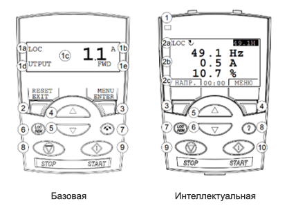
На частотники данной серии могут устанавливаться два типа панелей: базовая и интеллектуальная.
Типы сообщений
Индикация
Коды отказов частотника
Коды предупреждений частотника
Коды предупреждений частотника на базовой панели
Типы сообщений
Существует два типа сообщений: предупреждения и отказы.
Предупреждение. Код сопровождается буквой A (на базовой панели) или словом ПРЕДУПРЕЖД. / ALARM (на интеллектуальной панели). Выводятся в случае появления неаварийных ситуаций, на которые стоит обратить внимание. Предупреждение сбрасывается автоматически, если причина устранена.

Отказ. Код сопровождается буквой F (на базовой панели) или словом ОТКАЗ / FAULT (на интеллектуальной панели). В случае появления отказа двигатель останавливается во избежание повреждения самого частотника или другого оборудования. Для сброса отказов необходимо устранить причину отказа, затем, в случае мигания индикатора красным на панели или частотнике — отключить питание от ПЧ на 5 минут и подать его снова. Если индикатор непрерывно горит красным, то необходимо нажать RESET на панели управления или отключить питание от ПЧ на 5 минут и подать его снова.

Индикация
На панели и на частотнике присутствует индикатор с помощью которого можно определить наличие отказов или предупреждений.
Мигающий зеленый индикатор – обозначает предупреждение.
Мигающий или горящий красный индикатор – обозначает отказ.
Коды отказов частотника:
F0001 (ОТКАЗ 1 / FAULT 1) – слишком высокий выходной ток частотника;
возможные причины:
а) чрезмерная нагрузка двигателя;
б) недостаточное время ускорения (параметры 2202 и 2205);
в) неисправность двигателя, кабеля двигателя или соединений.
F0002 (ОТКАЗ 2 / FAULT 2) – слишком высокое напряжение промежуточного звена постоянного тока;
возможные причины:
а) постоянное или кратковременное превышение напряжения
в электросети;
б) недостаточное время замедления (параметры 2203 и 2206);
в) малая мощность тормозного прерывателя (если установлен);
г) убедитесь, что включен регулятор повышенного напряжения (параметр 2005).
F0003 (ОТКАЗ 3 / FAULT 3) – перегрев радиатора привода, температура достигла предельного значения или превышает его, для типоразмеров R1 .. R4 – 115 °C, для R5, R6 – 125 °C;
возможные причины:
а) отказ вентилятора;
б) препятствия на пути потока воздуха;
в) чрезмерно высокая температура окружающего воздуха;
г) чрезмерная нагрузка двигателя.
F0004 (ОТКАЗ 4 / FAULT 4) – короткое замыкание;
возможные причины:
а) короткое замыкание в двигателе или в кабеле (кабелях) двигателя;
б) помехи в электросети.
F0006 (ОТКАЗ 6 / FAULT 6) – недостаточное напряжение промежуточного звена постоянного тока;
возможные причины:
а) отсутствует напряжение в одной из фаз питания;
б) перегорел предохранитель;
в) пониженное напряжение сети.
F0007 (ОТКАЗ 7 / FAULT 7) – нет сигнала на аналоговом входе 1, величина сигнала аналогового входа меньше значения параметра 3021;
возможные причины:
а) источник сигнала и подключение аналогового входа;
б) значения параметров 3021 и 3001.
F0008 (ОТКАЗ 8 / FAULT  – нет сигнала на аналоговом входе 2, величина сигнала аналогового входа меньше значения параметра 3022;
возможные причины:
а) источник сигнала и подключение аналогового входа;
б) значения параметров 3022 и 3001.
F0009 (ОТКАЗ 9 / FAULT 9) – слишком высокая температура двигателя;
возможные причины:
а) двигатель перегружен;
б) неправильные значения параметров для вычисления температуры (3005…3009);
в) неисправность датчиков температуры или неверные значения параметров группы 35.
F0010 (ОТКАЗ 10 / FAULT 10) – нет связи с панелью и либо привод работает в режиме местного управления (на дисплее панели управления отображается LOC), или привод работает в режиме дистанционного управления (REM) и сконфигурирован для приема команд пуска/ останова, направления вращения или задания с панели управления;
возможные причины:
а) неисправность линии связи;
б) неправильное значение параметра 3002;
в) неправильные значения параметров из разделов 10 и 11.
F0011 (ОТКАЗ 11 / FAULT 11) – ошибка идентификационного прогона двигателя;
возможные причины:
а) неправильное подключение двигателя;
б) неправильные значения параметров 9905 … 9909.
F0012 (ОТКАЗ 12 / FAULT 12) – механическая блокировка (заклинивание) вала двигателя или технологического оборудования, двигатель работает в зоне блокировки (опрокидывания);
возможные причины:
а) чрезмерная нагрузка на валу двигателя;
б) недостаточна мощность двигателя;
в) неверные значения параметров 3010 … 3012.
F0014 (ОТКАЗ 14 / FAULT 14) – внешний отказ 1 (см. параметр 3001);
F0015 (ОТКАЗ 15 / FAULT 15) – внешний отказ 2 (см. параметр 3002);
F0016 (ОТКАЗ 16 / FAULT 16) – замыкание на землю;
возможные причины:
а) неисправности в цепи питания;
б) длина кабеля двигателя превышает максимально допустимое значение;
в) значение параметра 3028 слишком высокое;
г) питание по схеме заземленного треугольника и кабели двигателя с большой емкостью могут приводить к появлению ложных сообщений о неисправности при проверке на неподвижном двигателе.
F0018 (ОТКАЗ 18 / FAULT 18) – неисправность термистора частотника, обратитесь в сервисный центр.
F0019 (ОТКАЗ 19 / FAULT 19) – неисправность связи внутри частотника, обратитесь в сервисный центр.
F0020 (ОТКАЗ 20 / FAULT 20) – неисправность питания платы управления, обратитесь в сервисный центр.
F0021 (ОТКАЗ 21 / FAULT 21) – измеренное значение тока выходит за допустимые пределы, обратитесь в сервисный центр.
F0022 (ОТКАЗ 22 / FAULT 22) – слишком большие пульсации напряжения звена постоянного тока;
возможные причины:
а) оборвана одна из фаз электросети;
б) перегорел предохранитель.
F0023 (ОТКАЗ 23 / FAULT 23) – частотник не получает правильный сигнал энкодера;
возможные причины:
а) правильность подключения (неправильное соединение = канал А подключен к выводу канала В или наоборот, оборвано соединение или короткое замыкание);
б) логические уровни напряжения выходят за пределы допустимого диапазона;
в) неправильная работа и подключение интерфейсного модуля импульсного энкодера OTAC-01;
г) неправильная установка параметра 5001, неправильная величина может быть обнаружена только в случае, если ошибка такова, что расчетное скольжение превышает номинальное скольжение двигателя более, чем в 4 раза;
д) энкодер не используется, а значение параметра 5002 равно 1.
F0024 (ОТКАЗ 24 / FAULT 24) – скорость вращения двигателя превышает (по абсолютной величине) 120 % от большего из значений параметров 2001 и 2002;
возможные причины:
а) неправильные значения параметров 2001 и 2002;
б) несоответствие тормоза моменту двигателя;
в) в режиме регулирования момента скорость достигла максимального значения;
г) неисправны тормозной прерыватель или тормозной резистор.
F0026 (ОТКАЗ 26 / FAULT 26) – неверный идентификатор частотника в конфигурации, обратитесь в сервисный центр.
F0027 (ОТКАЗ 27 / FAULT 27) – ошибка файла конфигурации частотника, обратитесь в сервисный центр.
F0028 (ОТКАЗ 28 / FAULT 28) – истекло время ожидания связи по шине fieldbus;
возможные причины:
а) неверные настройки функции обработки отказов (параметры 3018 и 3019);
б) неверные настройки связи (группы параметров 51 и 53);
в) плохой контакт в разъемах и/или помехи в линии.
F0029 (ОТКАЗ 29 / FAULT 29) – ошибка файла конфигурации шины fieldbus.
F0030 (ОТКАЗ 30 / FAULT 30) – принудительное отключение по fieldbus.
F0034 (ОТКАЗ 34 / FAULT 34) – нет напряжения на фазе двигателя;
возможные причины:
а) неисправность двигателя;
б) неисправность кабеля двигателя;
в) неисправность термореле (если используется);
г) внутренний отказ.
F0035 (ОТКАЗ 35 / FAULT 35) – неправильное подключение кабеля питания и кабеля двигателя (кабель сетевого питания подключен к клеммам привода, предназначенным для подключения двигателя), сообщение об отказе может оказаться ложным, если питание включено по схеме заземленного треугольника и кабель двигателя имеет большую емкость, данный отказ можно запретить с помощью параметра 3023;
возможные причины:
а) неправильно подключена питающая сеть или заземление.
F0036 (ОТКАЗ 36 / FAULT 36) – частотник не может работать с программным обеспечением, возможно потребуется обращение в сервисный центр;
возможные причины:
а) внутренний отказ;
б) загруженное программное обеспечение несовместимо с частотником.
F0037 (ОТКАЗ 37 / FAULT 37) – перегрев платы управления привода, предельная температура отключения при неисправности равна 88 °C (не относится к частотникам с платой управления OMIO);
возможные причины:
а) чрезмерно высокая температура окружающего воздуха;
б) отказ вентилятора;
в) препятствия на пути потока воздуха.
F0038 (ОТКАЗ 38 / FAULT 38) – неверно задана кривая нагрузки, состояние, определяемое параметром 3701 сохраняется дольше, чем время, заданное в параметре 3703.
F0101 (ОТКАЗ 101 / FAULT 101) … F0199 (ОТКАЗ 199 / FAULT 199) – внутренняя ошибка привода, обратитесь в сервисный центр.
F0201 (ОТКАЗ 201 / FAULT 201) … F0299 (ОТКАЗ 299 / FAULT 299) – внутренняя ошибка привода, обратитесь в сервисный центр.
F- (ОТКАЗ — / FAULT -) – установленная панель не поддерживается;
F1000 (ОТКАЗ 1000 / FAULT 1000) – несовместимые значения параметров;
возможные причины:
а) значение параметра 2001 > значения параметра 2002;
б) значение параметра 2007 > значения параметра 2008;
в) значения параметров 2001/9908 за пределами допустимого диапазона (> 50);
г) значения параметров 2002/9908 за пределами допустимого диапазона (> 50);
д) значения параметров 2007/9908 за пределами допустимого диапазона (> 50);
е) значения параметров 2008/9908 за пределами допустимого диапазона (> 50).
F1001 (ОТКАЗ 1001 / FAULT 1001) – несовместимые значения параметров;
возможные причины:
а) значение параметра 2007 имеет отрицательное значение, когда активен параметр 8123.
F1003 (ОТКАЗ 1003 / FAULT 1003) – несовместимые значения параметров;
возможные причины:
а) значение параметра 1301 > значения параметра 1302;
б) значение параметра 1304 > значения параметра 1305.
F1004 (ОТКАЗ 1004 / FAULT 1004) – несовместимые значения параметров;
возможные причины:
а) значение параметра 1504 > значения параметра 1505;
б) значение параметра 1510 > значения параметра 1511.
F1005 (ОТКАЗ 1005 / FAULT 1005) – несовместимые значения параметров;
возможные причины:
а) не выполняется условие: 1,1 ≤ (значение параметра 9906 * значение параметра 9905 * 1,73 / (1000* значение параметра 9909)) ≤ 3.
F1006 (ОТКАЗ 1006 / FAULT 1006) – несовместимые значения параметров;
возможные причины:
а) дополнительный релейный модуль не подключен;
б) значения параметров 1410 … 1412 имеют нулевые значения.
F1007 (ОТКАЗ 1007 / FAULT 1007) – несовместимые значения параметров;
возможные причины:
а) установлено управление по шине fieldbus, но значение параметра 9802 равно 0.
F1008 (ОТКАЗ 1008 / FAULT 1008) – несовместимые значения параметров;
возможные причины:
а) значение параметра 9904 не равно 3, когда активирован параметр 8123.
F1009 (ОТКАЗ 1009 / FAULT 1009) – несовместимые значения параметров;
возможные причины:
а) не выполняется условие: 1 ≤ (60 * значение параметра 9906 / значение параметра 9908) ≤ 16;
б) не выполняется условие: 0,8 ≤ значение параметра 9908 / (120* значение параметра 9907) ≤ 0,992.
F1012 (ОТКАЗ 1012 / FAULT 1012) – несовместимые значения параметров;
возможные причины:
а) конфигурация ввода/вывода не соответствует требованиям – недостаточно реле для обеспечения режима PFC;
б) конфликт между параметрами 8117 и 8118.
F1013 (ОТКАЗ 1013 / FAULT 1013) – несовместимые значения параметров;
возможные причины:
а) Конфигурация ввода/вывода не соответствует требованиям – фактическое число двигателей для режима PFC (параметр 8127) не соответствует значениям параметров двигателей PFC из раздела группы 14 и параметру 8118.
F1014 (ОТКАЗ 1014 / FAULT 1014) – несовместимые значения параметров;
возможные причины:
а) конфигурация ввода/вывода не соответствует требованиям – в приводе не назначены цифровые входы (блокировки) для каждого двигателя системы PFC.
F1016 (ОТКАЗ 1016 / FAULT 1016) – несовместимые значения параметров;
возможные причины:
а) не выполняется условие: значение параметра 3704 ≤ значение параметра 3707 ≤ значение параметра 3710 ≤ значение параметра 3713 ≤ значение параметра 3716;
б) не выполняется условие: значение параметра 3705 ≤ значение параметра 3706;
в) не выполняется условие: значение параметра 3708 ≤ значение параметра 3709;
г) не выполняется условие: значение параметра 3711 ≤ значение параметра 3712;
д) не выполняется условие: значение параметра 3714 ≤ значение параметра 3715;
е) не выполняется условие: значение параметра 3717 ≤ значение параметра 3718.
Коды предупреждений частотника:
A2001 (ПРЕДУПРЕЖД. 2001 / ALARM 2001) – включен регулятор ограничения тока;
возможные причины:
а) чрезмерная нагрузка двигателя;
б) недостаточное время ускорения (параметры 2202 и 2205);
в) неисправность двигателя, кабеля двигателя или соединений.
A2002 (ПРЕДУПРЕЖД. 2002 / ALARM 2002) – включен регулятор повышенного напряжения;
возможные причины:
а) постоянное или кратковременное превышение напряжения в электросети;
б) недостаточное время замедления (параметры 2202 и 2206).
A2003 (ПРЕДУПРЕЖД. 2003 / ALARM 2003) – включен регулятор пониженного напряжения;
возможные причины:
а) пониженное напряжение сети.
A2004 (ПРЕДУПРЕЖД. 2004 / ALARM 2004) – запрещено изменение направления вращения;
возможные причины:
а) попытка изменить направление вращения двигателя.
A2005 (ПРЕДУПРЕЖД. 2005 / ALARM 2005) – истекло время ожидания связи по шине fieldbus;
возможные причины:
а) неправильно заданы параметры 3018 и 3019;
б) неправильные настройки связи (группы параметров 51 и 53);
в) плохой контакт в разъемах и/или помехи в линии.
A2006 (ПРЕДУПРЕЖД. 2006 / ALARM 2006) – нет сигнала на аналоговом входе 1 или значение сигнала меньше минимально допустимого;
возможные причины:
а) несоответствующий источник на входе или неверное подключение;
б) неверно задан параметр 3021;
в) неверно задан параметр 3001.
A2007 (ПРЕДУПРЕЖД. 2007 / ALARM 2007) – нет сигнала на аналоговом входе 2 или значение сигнала меньше минимально допустимого;
возможные причины:
а) несоответствующий источник на входе или неверное подключение;
б) неверно задан параметр 3022;
в) неверно задан параметр 3001.
A2008 (ПРЕДУПРЕЖД. 2008 / ALARM 2008) – нет связи с панелью управления и либо частотник работает в режиме местного управления (на дисплее панели управления отображается LOC), или привод работает в режиме дистанционного управления (REM) и сконфигурирован для приема команд пуска/останова, направления вращения или задания с панели управления;
возможные причины:
а) неисправны линии связи или их подключение;
б) неверно значение параметра 3002;
в) неверны значения параметров группы 10 и 11 ((если привод работает в режиме дистанционного управления (REM)).
A2009 (ПРЕДУПРЕЖД. 2009 / ALARM 2009) – радиатор охлаждения привода горячий, этот сигнал предупреждает, что скоро может произойти отказ по перегреву, для типоразмеров R1 .. R4 – 100 °C, для R5, R6 – 110 °C;
возможные причины:
а) отказ вентилятора;
б) препятствия на пути потока воздуха;
в) радиатор покрыт грязью или пылью;
г) чрезмерно высокая температура окружающего воздуха;
д) чрезмерная нагрузка двигателя.
A2010 (ПРЕДУПРЕЖД. 2010 / ALARM 2010) – высокая температура двигателя (значение вычислено приводом или измерено датчиком), этот сигнал предупреждает, что скоро может произойти отказ;
возможные причины:
а) двигатель перегружен;
б) установлены неверные значения для вычисления температуры (параметры 3005 … 3009);
в) неисправны датчики температуры или неверные значения параметров из группы 35.
A2012 (ПРЕДУПРЕЖД. 2012 / ALARM 2012) – двигатель работает в зоне блокировки (опрокидывания), этот сигнал предупреждает, что вскоре может произойти защитное отключение из-за блокировки двигателя.
A2013 (ПРЕДУПРЕЖД. 2013 / ALARM 2013) – этот сигнал предупреждения извещает о начале выполнения операции автоматического сброса отказа, в результате чего возможен пуск двигателя, для управления автоматическим сбросом необходимо установить параметры группы 31.
A2014 (ПРЕДУПРЕЖД. 2014 / ALARM 2014) – этот сигнал предупреждения извещает, что активна функция авточередования PFC, данная функция управляется параметрами раздела 81: Управление PFC, Мактор PFC.
A2015 (ПРЕДУПРЕЖД. 2015 / ALARM 2015) – этот сигнал предупреждает о том, что активны блокировки PFC, т. е. привод не может запустить ни один из двигателей (когда используется функция чередования), двигатель с регулируемой скоростью (если функция авточередования не используется).
A2018 (ПРЕДУПРЕЖД. 2018 / ALARM 2018) – этот сигнал предупреждает о том, что ПИД-регулятор находится в спящем режиме, т. е. разгон двигателя возможен только после отключения функции спящего режима, для управления режима сна ПИД-регулятора служат параметры 4022 … 4026 или 4122 … 4126.
A2019 (ПРЕДУПРЕЖД. 2019 / ALARM 2019) – выполнение идентификационного прогона.
A2021 (ПРЕДУПРЕЖД. 2021 / ALARM 2021) – этот сигнал предупреждает, что отсутствует сигнал разрешения пуска 1, управление осуществляется параметром 1608;
возможные причины:
а) неверная конфигурация цифровых входов;
б) неверные параметры связи.
A2022 (ПРЕДУПРЕЖД. 2022 / ALARM 2022) – этот сигнал предупреждает, что отсутствует сигнал разрешения пуска 2, управление осуществляется параметром 1609;
возможные причины:
а) неверная конфигурация цифровых входов;
б) неверные параметры связи.
A2023 (ПРЕДУПРЕЖД. 2023 / ALARM 2023) – включен аварийный останов;
A2024 (ПРЕДУПРЕЖД. 2024 / ALARM 2024) – привод не получает правильный сигнал энкодера;
возможные причины:
а) энкодер имеется и соответственно подключен (перепутаны провода, плохой контакт или короткое замыкание);
б) логические уровни напряжения выходят за пределы допустимого диапазона;
в) работа и правильность подключения интерфейсного модуля импульсного энкодера OTAC-01;
г) неправильная установка параметра 5001, неправильная величина может быть обнаружена только в случае, если ошибка такова, что расчетное скольжение превышает номинальное скольжение двигателя более чем в 4 раза.
A2025 (ПРЕДУПРЕЖД. 2025 / ALARM 2025) – сигнализирует, что привод рассчитывает характеристики двигателя в процессе первого пуска, обычно это относится к случаю, когда двигатель первый раз запускается после ввода или изменения его параметров (см. параметр 9910).
A2027 (ПРЕДУПРЕЖД. 2027 / ALARM 2027) – этот сигнал показывает, что состояние, определяемое параметром 3701 сохраняется дольше, чем время, заданное параметром 3703.
A2028 (ПРЕДУПРЕЖД. 2028 / ALARM 2028) – сигнал действует в процессе пуска (см. параметр 2113).
Коды предупреждений частотника на базовой панели:
A5001 – привод не отвечает;
A5002 – профиль связи несовместим с приводом;
A5010 – поврежден резервный файл параметров панели управления;
A5011 – привод управляется другим устройством;
A5012 – изменение направления вращения заблокировано;
A5013 – кнопка заблокирована, поскольку пуск запрещен;
A5014 – кнопка заблокирована, поскольку привод неисправен;
A5015 – кнопка заблокирована, т.к. включена блокировка режима местного управления;
A5018 – невозможно найти значение параметра по умолчанию;
A5019 – запись величины, отличной от нуля, запрещена;
A5020 – группа или параметр не существует или несовместимое значение параметра;
A5021 – группа или параметр скрыты;
A5022 – группа (или параметр) защищена от записи;
A5023 – изменения недопустимы при вращении привода;
A5024 – привод занят, попытайтесь снова;
A5025 – запись не допускается в процессе загрузки или выгрузки;
A5026 – величина равна или ниже нижнего предельного значения;
A5027 – величина равна или выше верхнего предельного значения;
A5028 – величина не согласуется с величинами в перечне дискретных величин;
A5029 – память не готова, попытайтесь снова;
A5030 – неверный запрос;
A5031 – привод не готов, например, из-за низкого напряжения звена постоянного тока;
A5032 – обнаружена ошибка параметра;
A5040 – выбранный набор параметров не найден в текущей резервной копии параметров;
A5041 – резервная копия параметров не умещается в памяти;
A5042 – выбранный набор параметров не найден в текущей резервной копии параметров;
A5043 – запрет пуска не предоставлен;
A5044 – версии резервных копий параметров не согласуются;
A5050 – загрузка параметров была прервана;
A5051 – обнаружена ошибка файла;
A5052 – попытка выгрузки параметров не удалась;
A5060 – загрузка параметров была прервана;
A5062 – попытка загрузки параметров не удалась;
A5070 – обнаружена ошибка записи в дублирующую память панели;
A5071 – обнаружена ошибка чтения из дублирующей памяти панели;
A5080 – операция не допускается, поскольку привод работает не в режиме местного управления;
A5081 – операция невозможна из-за наличия действующего отказа;
A5083 – операция не допускается, поскольку не снята блокировка параметра;
A5084 – операция невозможна, т. к. привод занят, попытайтесь еще раз;
A5085 – загрузка данных невозможна из-за несовместимости типов приводов;
A5086 – загрузка данных невозможна из-за несовместимости моделей приводов;
A5087 – загрузка невозможна, т.к. наборы параметров не согласуются;
A5088 – операция не выполнена, т. к. обнаружена ошибка в памяти привода;
A5089 – загрузка данных не выполнена, поскольку была обнаружена ошибка контрольной суммы;
5090 – загрузка данных не выполнена, поскольку была обнаружена ошибка обработки данных;
A5091 – операция не выполнена, т. к. обнаружена ошибка параметра;
A5092 – загрузка не выполнена, т.к. наборы параметров не согласуются.
Если вам не удалось разобраться с проблемой самостоятельно обращайтесь в наш сервисный центр. Квалифицированный инженер проведет диагностику неисправного преобразователя и отремонтирует его.
ACS510 User’s Manual
Fault
Code
16
17
18
19
20
21
22
23
24
25
26
27
28
29
30
31
32
33
34
Supplied from China by: Guangzhou Tofee Electro Mechanical Equipment Co., Ltd
Email: info@tofee.com.cn
Fault Name In
Panel
Possible ground fault detected in the motor or motor cables. The drive
EARTH FAULT
monitors for ground faults while the drive is running and while the drive is
not running. Detection is more sensitive when the drive is not running and
can produce false positives.
Possible corrections:
• Check for/correct faults in the input wiring.
• Verify that motor cable does not exceed maximum specified length.
• A delta grounded input power supply and motor cables with high
capacitance may result in erroneous error reports during non-running
tests. To disable response to fault monitoring when the drive is not
running, use parameter 3023
ground fault monitoring, use parameter 3017
RESERVED
Internal fault. The thermistor measuring the internal temperature of the
THERM FAIL
drive is open or shorted. Contact your local ABB representative.
Internal fault. A communication-related problem has been detected on the
OPEX LINK
fiber optic link between the control and OINT boards. Contact your local
ABB sales representative.
Internal fault. Low voltage condition detected on OINT power supply.
OPEX PWR
Contact your local ABB representative.
Internal fault. Current measurement is out of range. Contact your local ABB
CURR MEAS
representative.
Ripple voltage in the DC link is too high. Check for and correct:
SUPPLY PHASE
• Missing mains phase.
• Blown fuse.
If this error code appears, refer to the appropriate accessory manual.
Not used.
RESERVED
Not used.
RESERVED
Internal fault. Configuration Block Drive ID is not valid. Contact your local
DRIVE ID
ABB sales representative.
Internal configuration file has an error. Contact your local ABB sales
CONFIG FILE
representative.
1
Fieldbus communication has timed out. Check for and correct:
SERIAL
ERR
• Fault setup (3018
• Communication settings (Group 51 or 53 as appropriate).
• Poor connections and/or noise on line.
Error in reading the configuration file for the embedded fieldbus.
EFB CON FILE
Fault trip forced by the fieldbus. See the fieldbus User’s Manual.
FORCE TRIP
1
Fault code reserved for the embedded fieldbus (EFB) protocol application.
EFB
The meaning is protocol dependent.
2
EFB
3
EFB
Fault in the motor circuit. One of the motor phases is lost. Check for and
MOTOR PHASE
correct:
• Motor fault.
• Motor cable fault.
• Thermal relay fault (if used).
• Internal fault.
Description and Recommended Corrective Action
WIRING FAULT
COMM FAULT FUNC
. To disable response to all
.
EARTH FAULT
and 3019
).
COMM FAULT TIME
Diagnostics
199

-
Contents
-
Table of Contents
-
Bookmarks
Quick Links
IT
Drive
Low Voltage AC Drives
User’s Manual
ACS510-01 Drives (1.1
Supplied from China by: Guangzhou Tofee Electro Mechanical Equipment Co., Ltd
Email: info@tofee.com.cn
160 kW)
…
Related Manuals for ABB ACS510-01
Summary of Contents for ABB ACS510-01
-
Page 1
Drive Low Voltage AC Drives User’s Manual ACS510-01 Drives (1.1 160 kW) … Supplied from China by: Guangzhou Tofee Electro Mechanical Equipment Co., Ltd Email: info@tofee.com.cn… -
Page 2
ACS510 User’s Manual ACS510 Drive Manuals The Industrial wordmark and Product names in the form Drive are registered or pending trademarks of ABB. GENERAL MANUALS CANopen is a registered trademark of CAN in Automation e.V. ACS510-01 User’s Manual (1.1…160 kW) ControlNet is a registered trademark of ControlNet •… -
Page 3
Warning! The ACS510-01 is not a field repairable unit. Never attempt to repair a malfunctioning unit; contact the factory or your local Authorized Service Center for replacement. -
Page 4: Safety
ACS510 User’s Manual Use of Warnings and Notes There are two types of safety instructions throughout this manual: • Notes draw attention to a particular condition or fact, or give information on a subject. • Warnings caution you about conditions which can result in serious injury or death and/or damage to the equipment.
-
Page 5: Table Of Contents
Diagnostics – FBA ……….183 ABB Drives Profile Technical Data ……. . . 186 Generic Profile Technical Data .
-
Page 6
ACS510 User’s Manual Maintenance Maintenance Intervals ……… . . 207 Heatsink . -
Page 7: Installation
ACS51 User’s Manual Installation Study these installation instructions carefully before proceeding. Failure to observe the warnings and instructions may cause a malfunction or personal hazard. Warning! Before you begin read «Safety» on page 3. Installation Flow Chart The installation of the ACS510 adjustable speed AC drive follows the outline below. The steps must be carried out in the order shown.
-
Page 8: Preparing For Installation
Drive Identification Drive Labels To determine the type of drive you are installing, refer to either: • Serial number label attached on upper part of the chokeplate between the mounting holes, or ACS510-01-09A4-4+N688 3~ 380…480 V 9.4 A Ser. no. *3050700001* 4 kW •…
-
Page 9
User’s Manual Type Code Use the following chart to interpret the type code found on either label. ACS510-01-09A4-4+… AC, Standard Drive – 510 product series Construction (region specific) 01 = Wall mounting (Setup and parts specific to IEC installation and compliance) Output current rating e.g. -
Page 10
ACS510 User’s Manual • Tape measure • Drill • Mounting hardware: screws or nuts and bolts, four each. The type of hardware depends on the mounting surface and the frame size: Frame Size Mounting Hardware R1…R4 1/4 in 5/16 in Suitable Environment and Enclosure Confirm that the site meets the environmental requirements. -
Page 11: Installing The Drive
ACS51 User’s Manual Installing the Drive Warning! Before installing the ACS510, ensure the input power supply to the drive is off. Prepare the Mounting Location The ACS510 should only be mounted where all of the requirements defined in «Preparing for Installation» on page 8 are met.
-
Page 12
ACS510 User’s Manual IP54 1. If hood is present: Remove screws (2) holding hood in place. 2. If hood is present: Slide hood up and off of the cover. 3. Loosen the captive screws around the edge of the cover. 4. -
Page 13
Warning! Ensure the motor is compatible for use with the ACS510. The ACS510 must be installed by a competent person in accordance with the considerations defined in «Preparing for Installation» on page 8. If in doubt, contact your local ABB sales or service office. -
Page 14
Braking resistor. See «Brake Components» on page 225. R3, R4, R5, R6 UDC+, UDC- DC bus Contact your ABB representative to order either: • Braking unit or • Chopper and resistor • When installing control wiring, refer to the following sections, as appropriate: –… -
Page 15
ACS51 User’s Manual Power Connection Diagrams The following diagram shows the terminal layout for frame size R3, which, in general, applies to frame sizes R1 R6, except for the R5/R6 power and ground … terminals. Diagram shows the R3 frame. J1 –… -
Page 16
ACS510 User’s Manual The following diagram shows the power and ground terminal layout for frame sizes R5 and R6 X0011 Power Output to Motor Power Input (U2, V2, W2) (U1, V1, W1) Optional braking Frame Terminal Brake Options Size Labels R5, R6 UDC+, UDC- •… -
Page 17
ACS51 User’s Manual Control Terminals Table The following provides information for connecting control wiring at X1 on the drive. Hardware Description Terminal for signal cable screen. (Connected internally to chassis ground.) Analog input channel 1, programmable. Default = frequency reference. Resolution 0.1%, accuracy ±1%. -
Page 18
ACS510 User’s Manual macro. See «Application Macros» on page 42. Note! Terminals 3, 6, and 9 are at the same potential. Note! For safety reasons the fault relay signals a “fault” when the ACS510 is powered down. You can wire the digital input terminals in either a PNP or NPN configuration. PNP connection (source) NPN connection (sink) 10 +24 V… -
Page 19
ACS51 User’s Manual Wiring IP21 Enclosure with Cables 1. Open the appropriate knockouts in the conduit/gland box. (See «Conduit/Gland Kit» above.) 2. Install the cable clamps for the power/motor cables. X0004 3. On the input power cable, strip the sheathing back far enough to route individual wires. -
Page 20
ACS510 User’s Manual Wiring IP21 Enclosure with Conduit 1. Open the appropriate knockouts in the conduit/gland box. (See «Conduit/Gland Kit» above.) 2. Install thin-wall conduit clamps (not supplied). X0007 3. Install conduit/gland box. 4. Connect conduit runs to box. X0005 5. -
Page 21
ACS51 User’s Manual Wiring IP54 Enclosure with Cables 1. Cut the cable seals as needed for the power, motor, and control cables. (The cable seals are cone-shaped, rubber seals on the bottom of the drive.) IP5003 2. On the input power cable, strip the sheathing back far enough to route individual wires. -
Page 22
ACS510 User’s Manual 6. Connect the pig-tail created from the motor cable screen to the GND terminal. 7. Strip control cable sheathing and twist the copper screen into a pig-tail. 8. Route control cable(s) through clamp(s) and tighten clamp(s). 9…11 9. -
Page 23
ACS51 User’s Manual Wiring IP54 Enclosure with Conduit 1. Depends on Frame Size: R1…R4 • R1…R4: Remove and discard the cable seals where conduit will be installed. (The cable seals are cone-shaped, rubber seals on the bottom of the drive.) IP5013 •… -
Page 24
ACS510 User’s Manual Check Installation Before applying power, perform the following checks. Check Installation environment conforms to the drive’s specifications for ambient conditions. The drive is mounted securely. Space around the drive meets the drive’s specifications for cooling. The motor and driven equipment are ready for start. For floating networks: The internal RFI filter is disconnected (screws EM1 &… -
Page 25
ACS51 User’s Manual Re-install Cover IP21 1. Align the cover and slide it on. 2. Tighten the captive screw. 3. Re-install the control panel. IP2009 IP54 1. Align the cover and slide it on. 2. Tighten the captive screws around the edge of the cover. -
Page 26
ACS510 User’s Manual Apply Power Always re-install the front cover before turning power on. Warning! The ACS510 will start up automatically at power up, if the external run command is on. 1. Apply input power. When power is applied to the ACS510, the green LED comes on. Note! Before increasing motor speed, check that the motor is running in the desired direction. -
Page 27
ACS51 User’s Manual • Basic Control Panel: Refer to «Parameters Mode» on page 39, for parameter editing instructions. Tuning – Parameters The system can benefit from one or more of the ACS510 special features, and/or fine tuning. 1. Review the parameter descriptions in «Complete Parameter Descriptions» starting on page 63. -
Page 28: Start-Up
ACS510 User’s Manual Start-Up Start-up configures the drive. This process sets parameters that define how the drive operates and communicates. Depending on the control and communication requirements, the start-up process may require any or all of the following: • Application macros can be selected to define common, alternate system configurations, using the default settings.
-
Page 29
ACS510 User’s Manual Controls/Display Overview The following table summarizes the button functions and displays on the Assistant Control Panel. LCD Display – Divided into three main areas: • Top line – variable, depending on the mode of operation. For example, see «Status Information»… -
Page 30
ACS510 User’s Manual Status Information Top. The top line of the LCD display shows the basic status information of the drive. • LOC – indicates that the drive control is local, that is, from the control panel. • REM – indicates that the drive control is remote, such as the basic I/O (X1) or fieldbus. -
Page 31
ACS510 User’s Manual • Release the button while LOCAL CONTROL is displayed to set the panel reference to the current external reference. The drive stops. • Release the button when LOCAL, KEEP RUN is displayed, to copy the current run/stop status and the reference from the user I/O. To switch back to remote control (REM) press and hold the button until REMOTE CONTROL is displayed. -
Page 32
ACS510 User’s Manual 2. Press UP/DOWN to highlight the appropriate parameter group, then press SEL. 3. Press UP/DOWN to highlight the appropriate parameter in a group. NOTE! The current parameter value appears below the highlighted parameter. 4. Press EDIT. 5. Press UP/DOWN to step to the desired parameter value. Note! To view the parameter default value: In the set mode, press UP/DOWN simultaneously. -
Page 33
ACS510 User’s Manual Changed Parameters Mode Use the Changed Parameters mode to view (and edit) a listing of all parameters that have been changed from macro default values. Procedure: 1. Select CHANGED PAR in the Main Menu. The display lists all changed parameters. 2. -
Page 34
ACS510 User’s Manual Note! Download Full Set writes all parameters to the drive, including motor parameters. Only use this function to restore a drive, or to transfer parameters to systems that are identical to the original system. • Download Application – Copies a partial parameter set from the Control Panel to a drive. -
Page 35
ACS510 User’s Manual 1. Highlight an item type in the Differences List (left screen below) and press SEL to see the details for the selected type (right screen below). DIFFERENCES —- INVALID VAL VALUES UNDER MIN 9902 APLIC MACRO VALUES OVER MAX 2606*SWITCHING FREQ 12 kHz INVALID VALUES… -
Page 36
ACS510 User’s Manual 2. Press UP/DOWN to step to the desired I/O group, for example, digital inputs. 3. Press ENTER. 4. Press UP/DOWN to step to a particular item, for example DI1. After a brief pause, the displays shows the current setting for the selection. 5. -
Page 37: Basic Control Panel
ACS510 User’s Manual Basic Control Panel Features The Basic Control Panel features: • Numeric control panel with a LCD display. • Drive connection that can be made or detached at any time • Copy function – Parameters can be copied to the Control Panel memory for later transfer to other drives, or for backup of a particular system.
-
Page 38
ACS510 User’s Manual Status Information When the Basic Control Panel is in the Output mode, the display: • Top-left shows the control location: – LOC – indicates that the drive control is local, that is, from the control panel. OUTPUT –… -
Page 39
ACS510 User’s Manual Shaft direction – To change the shaft direction press DIR (parameter 1003 must be set to 3 ( REQUEST Reference – See «Reference Mode» below. Reference Mode Use the Reference Mode to set the frequency reference. Normally this reference control is only possible when the drive is under Local (LOC) control. -
Page 40
ACS510 User’s Manual 4. Use UP or DOWN arrow key to step through to the desired group, for example “03”. 5. Press MENU/ENTER. The display shows one of the parameters in the selected parameter group. For example, “0301”. 6. Use UP or DOWN arrow key to step through to the desired parameter. 7. -
Page 41
ACS510 User’s Manual • dL P (Download Partial) – Copies a partial parameter set from the Control Panel to a drive. The partial set does not include internal motor parameters, parameters 9905…9909, 1605, 1607, 5201, nor any Group 51 and Group 53 parameters. Use this option to transfer parameters to systems that use similar configurations –… -
Page 42: Application Macros
Application macros are enabled by setting the value for parameter 9902 APPLIC . By default, 1, ABB Standard, is the enabled macro. MACRO The following sections describe each of the application macros and provide a connection example for each macro.
-
Page 43
ACS510 User’s Manual Application Macro: ABB Standard (Default) This macro provides a general purpose, 2-wire I/O configuration, with three (3) constant speeds. This is the default macro. Parameter values are the default values defined in the «Complete Parameter List for ACS510» on page 52. -
Page 44
ACS510 User’s Manual Application Macro: 3-wire This macro is used when the drive is controlled using momentary push-buttons, and provides three (3) constant speeds. To enable, set the value of parameter 9902 to 2 WIRE Note! When the stop input ( 2) is deactivated (no input), the control panel start/stop buttons are disabled. -
Page 45
ACS510 User’s Manual Application Macro: Alternate This macro provides an I/O configuration adopted to a sequence of DI control signals used when alternating the rotation direction of the drive. To enable, set the value of parameter 9902 to 3 ( ALTERNATE Connection example: Signal cable shield (screen) -
Page 46
ACS510 User’s Manual Application Macro: Motor Potentiometer This macro provides a cost-effective interface for PLCs that vary the speed of the drive using only digital signals. To enable, set the value of parameter 9902 to 4 MOTOR POT Connection example: Signal cable shield (screen) Not used AGND… -
Page 47
ACS510 User’s Manual Application macro: Hand-Auto This macro provides an I/O configuration that is typically used in HVAC applications. To enable, set the value of parameter 9902 to 5 ( HAND AUTO Note! Parameter 2108 must remain in the default setting, 0 ( START INHIBIT Connection example: Signal cable shield (screen) -
Page 48
ACS510 User’s Manual Application Macro: PID Control This macro provides parameter settings for closed-loop control systems such as pressure control, flow control, etc. To enable, set the value of parameter 9902 to 6 PID CTRL Note! Parameter 2108 must remain in the default setting, 0 ( START INHIBIT Connection example: Signal cable shield (screen) -
Page 49
ACS510 User’s Manual Application Macro: PFC This macro provides parameter settings for pump and fan control (PFC) applications. To enable, set the value of parameter 9902 to 7 ( PFC CONTROL Note! Parameter 2108 must remain in the default setting, 0 ( START INHIBIT Connection example: Signal cable shield (screen) -
Page 50
ACS510 User’s Manual Application Macro: SPFC This macro provides parameter settings for pump and fan control (PFC) applications with cycle soft start function. To enable, set the value of parameter 9902 to 15 ( SPFC CONTROL Note! Parameter 2108 must remain in the default setting, 0 ( START INHIBIT Connection example: Signal cable shield (screen) -
Page 51
Macro Default Values for Parameters Parameter default values are listed in «Complete Parameter List for ACS510». Changing from the default macro (ABB Standard), that is, editing the value of parameter 9902, changes the parameter default values as defined in the following tables. -
Page 52: Complete Parameter List For Acs510
• User = Space to enter desired parameter values Some values vary depending on the drive software options. This is indicated by “+N688:” or “+N689 in the table below. Refer to the type code on the drive namplate. For example ACS510-01…+N688 . Code Name…
-
Page 53
ACS510 User’s Manual Code Name Range Resolution Default User S 0125 0.0…20.0 mA 0.1 mA 0126 -1000.0…1000.0% 0.1% OUTPUT 0127 -100.0…100.0% 0.1% OUTPUT 0128 Unit and scale defined by par. 4006/ SETPNT 4106 and 4007/4107 0129 Unit and scale defined by par. 4206 and SETPNT 4207 0130… -
Page 54
ACS510 User’s Manual Code Name Range Resolution Default User S 0402 Date dd.mm.yy / power-on time in days 1 day FAULT TIME 0403 Time hh.mm.ss FAULT TIME 0404 -32768 … +32767 1 rpm SPEED AT FLT 0405 -3276.8 … +3276.7 0.1 Hz FREQ AT FLT 0406… -
Page 55
ACS510 User’s Manual Code Name Range Resolution Default User S 1206 0.0…500.0 Hz / 0.1 Hz 25.0 Hz / CONST SPEED +N688:0.0…50.0 Hz / +N688:25.0 Hz / +N689:0.0…55.0 Hz +N689:27.5Hz 1207 0.0…500.0 Hz / 0.1 Hz 40.0 Hz / CONST SPEED +N688:0.0…50.0 Hz / +N688:40.0 Hz / +N689:0.0…55.0 Hz… -
Page 56
ACS510 User’s Manual Code Name Range Resolution Default User S 1511 0.0…20.0 mA 0.1 mA 20.0 mA MAXIMUM AO 1512 0.0…10.0 s 0.1 s 0.1 s FILTER AO Group 16: System Controls 1601 -6…7 RUN ENABLE 1602 0…2 PARAMETER LOCK 1603 0…65535 PASS CODE… -
Page 57
ACS510 User’s Manual Code Name Range Resolution Default User S Group 22: Accel/Decel 2201 -6…7 2202 0.0…1800.0 s 0.1 s 5.0 s ACCELER TIME 2203 0.0…1800.0 s 0.1 s 5.0 s DECELER TIME 2204 ; 0.1…1000.0 s 0.1 s 0.0 s RAMP SHAPE LINEAR 2205… -
Page 58
ACS510 User’s Manual Code Name Range Resolution Default User S 2613 0.0…500.0 Hz / 0.1 Hz 20.0 Hz / USER F +N688:0.0…50.0 Hz / +N688:20.0 Hz / +N689:0.0…55.0 Hz +N689:22.0 Hz 2614 0…480 V 228 V USER U 2615 0.0…500.0 Hz / 0.1 Hz 30.0 Hz / USER F… -
Page 59
ACS510 User’s Manual Code Name Range Resolution Default User S 3203 SUPERV LIM HI 3204 100…159 SUPERV PARAM 3205 SUPERV LIM LO 3206 SUPERV LIM HI 3207 100…159 SUPERV PARAM 3208 SUPERV LIM LO 3209 SUPERV LIM HI Group 33: Information 3301 0000…FFFF hex Firmware version… -
Page 60
ACS510 User’s Manual Code Name Range Resolution Default User S 3705 0%…600% LOAD TORQ LOW 3706 0%…600% 300% LOAD TORQ HIGH 3707 0…500 Hz 1 Hz 25 Hz LOAD FREQ 3708 0%…600% LOAD TORQ LOW 3709 0%…600% 300% LOAD TORQ HIGH 3710 0…500 Hz 1 Hz… -
Page 61
ACS510 User’s Manual Code Name Range Resolution Default User S 4026 0…60 s 0.01 s 0.50 s WAKE UP DELAY 4027 -6…7 PARAM Group 41: Process PID Set 2 4101 0.1…100 GAIN 4102 0.0s = , 0.1…3600 s 0.1 s 3.0 s INTEGRATION TIME NOT SEL… -
Page 62
2, 2 = 8 EFB PARITY NONE NONE EVEN 3 = 8 5305 , 1 = EFB CTRL PROFILE ABB DRV LIM DCU PROFILE ABB DRV LIM ABB DRV FULL 5306 0…65535 EFB OK MESSAGES 5307 0…65535 EFB CRC ERRORS 5308 0…65535… -
Page 63
ACS510 User’s Manual Code Name Range Resolution Default User S 5314 0…65535 EFB PAR NOT SEL 5315 0…65535 EFB PAR NOT SEL 5316 0…65535 EFB PAR NOT SEL 5317 0…65535 EFB PAR NOT SEL 5318 0…65535 EFB PAR 5319 0…0xFFFF (hex) EFB PAR 5320 0…0xFFFF (hex) -
Page 64: Complete Parameter Descriptions
This section describes the actual signals and parameters for ACS510. Some values vary depending on the drive software options. This is indicated by “+N688:” or “+N689 in the table below. Refer to the type code on the drive namplate. For example ACS510-01…+N688 Term Definition Actual signal Signal measured or calculated by the drive.
-
Page 65
ACS510 User’s Manual 9909 MOTOR NOM POWER Defines the nominal motor power. Must equal the value on the motor rating plate. Start-Up Supplied from China by: Guangzhou Tofee Electro Mechanical Equipment Co., Ltd Email: info@tofee.com.cn… -
Page 66
ACS510 User’s Manual Group 01: Operating Data This group contains drive operating data, including actual signals. The drive sets the values for actual signals, based on measurements or calculations. You cannot set these values. Code Description 0101 SPEED & DIR The calculated signed speed of the motor (rpm). -
Page 67
ACS510 User’s Manual Code Description 0118 DI 1-3 STATUS Status of the three digital inputs. • Status is displayed as a binary number. • 1 indicates that the input is activated. • 0 indicates that the input is deactivated. 0119 DI 4-6 STATUS Status of the three digital inputs. -
Page 68
ACS510 User’s Manual Code Description 0135 COMM VALUE 1 Free data location that can be written from serial link. 0136 COMM VALUE 2 Free data location that can be written from serial link. 0137 PROCESS VAR 1 Process variable 1 Defined by parameters in Group 34: Panel Display. -
Page 69
ACS510 User’s Manual Group 03: FB Actual Signals This group monitors fieldbus communications. Code Description 0301 FB CMD WORD 1 Bit # 0301, 0302, FB CMD WORD FB CMD WORD Read-only copy of the Fieldbus Command Word 1. STOP FBLOCAL_CTL •… -
Page 70
ACS510 User’s Manual 0305 FAULT WORD 1 Read-only copy of the Fault Word 1. Bit # 0305, 1 0306, 2 0307, FAULT WORD FAULT WORD FAULT WORD • When a fault is active, the OVERCURRENT Obsolete EFB 1 corresponding bit for the active fault DC OVERVOLT THERM FAIL EFB 2… -
Page 71
ACS510 User’s Manual Group 04: Fault History This group stores a recent history of the faults reported by the drive. Code Description 0401 LAST FAULT 0 — Clear the fault history (on panel = NO RECORD). n — Fault code of the last recorded fault. 0402 FAULT TIME 1 The day on which the last fault occurred. -
Page 72
ACS510 User’s Manual Group 10: Start/Stop/Dir This group: • Defines external sources ( 1, and 2) for commands that enable start, stop and direction changes. • Locks direction or enables direction control. To select between the two external locations use the next group (parameter 1102). Code Description 1001 EXT1 COMMANDS Defines external control location 1 (… -
Page 73
ACS510 User’s Manual Code Description 1002 EXT2 COMMANDS Defines external control location 2 ( 2) – the configuration of start, stop and direction commands. See parameter 1001 above. COMMANDS 1003 DIRECTION Defines the control of motor rotation direction. – Rotation is fixed in the forward direction. FORWARD –… -
Page 74
ACS510 User’s Manual Group 11: Reference Select This group defines: • How the drive selects between command sources. • Characteristics and sources for 1 and Code Description 1101 KEYPAD REF SEL Selects the reference controlled in local control mode. 1 (Hz) – Frequency reference as hertz. 2 (%) –… -
Page 75
ACS510 User’s Manual ) – Defines digital inputs as the frequency reference source (motor potentiometer control). • Digital input 3 increases the speed (the stands for “up”). • Digital input 4 decreases the speed (the stands for “down”). • A Stop command resets the reference to zero (the stands for “reset”). -
Page 76
ACS510 User’s Manual 1104 REF1 MIN Ext ref Sets the minimum for external reference 1. • The minimum analog input signal (as a percent of P 1105 the full signal in volts or amps) corresponds to in Hz. • Parameter 1301 1 or 1304 MINIMUM AI MINIMUM AI… -
Page 77
ACS510 User’s Manual Group 12: Constant Speeds This group defines a set of constant speeds. In general: • You can program up to 7 constant speeds. • Values must be positive (No negative speed values for constant speeds). • Constant speed selections are ignored if: –… -
Page 78
ACS510 User’s Manual Code Description 13 = 3,4,5 – Selects one of seven Constant Speeds (1…7) using 4 and • See above ( 1,2,3) for code. 14 = 4,5,6 – Selects one of seven Constant Speeds (1…7) using 6 and •… -
Page 79
ACS510 User’s Manual Group 13: Analog Inputs This group defines the limits and the filtering for analog inputs. Code Description 1301 MINIMUM AI1 Defines the minimum value of the analog input. • Define value as a percent of the full analog signal range. See example below. •… -
Page 80
ACS510 User’s Manual Group 14: Relay Outputs This group defines the condition that activates each of the relay outputs. Code Description 1401 RELAY OUTPUT 1 Defines the event or condition that activates relay 1 – what relay output 1 means. –… -
Page 81
ACS510 User’s Manual Code Description 35 = – Energize relay based on input from fieldbus communication. COMM • Fieldbus writes binary code in parameter 0134 that can energize relay 1…relay 6 according to the following: Par. 0134 Binary RO6 RO5 RO4 RO3 RO2 RO1 000000 000001 000010… -
Page 82
ACS510 User’s Manual Code Description 1410 RELAY OUTPUT 4…6 … Defines the event or condition that activates relay 4…6 – what relay output 4…6 means. 1412 See 1401 RELAY OUTPUT 1413 RO 4 ON DELAY Defines the switch-on delay for relay 4. ON DELAY 1414 RO 4 OFF DELAY Defines the switch-off delay for relay 4. -
Page 83
ACS510 User’s Manual Group 15: Analog Outputs This group defines the drive’s analog (current signal) outputs. The drive’s analog outputs can be: • Any parameter of the Operating Data group (Group 01). • Limited to programmable minimum and maximum values of output current. •… -
Page 84
ACS510 User’s Manual Code Description 1512 FILTER AO2 Defines the filter time constant for 2. See 1 above. FILTER AO Start-Up Supplied from China by: Guangzhou Tofee Electro Mechanical Equipment Co., Ltd Email: info@tofee.com.cn… -
Page 85
ACS510 User’s Manual Group 16: System Controls This group defines a variety of system level locks, resets and enables. Code Description 1601 RUN ENABLE Selects the source of the run enable signal. – Allows the drive to start without an external run enable signal. NOT SEL 1 –… -
Page 86
ACS510 User’s Manual Code Description 1605 USER PAR SET CHG Defines control for changing the user parameter set. • See parameter 9902 APPLIC MACRO • The drive must be stopped to change User Parameter Sets. • During a change, the drive will not start. Note: Always save the User Parameter Set after changing any parameter settings, or performing a motor identification. -
Page 87
ACS510 User’s Manual Code Description 1608 START ENABLE 1 Selects the source of the start enable 1 signal. Note: Start enable functionality differs from the run enable functionality. – Allows the drive to start without an external start enable signal. NOT SEL 1 –… -
Page 88
ACS510 User’s Manual Code Description 1609 START ENABLE 2 Selects the source of the start enable 2 signal. Note: Start enable functionality differs from the run enable functionality. – Allows the drive to start without an external start enable signal. NOT SEL 1 –… -
Page 89
ACS510 User’s Manual Group 17: Override This group defines the source for the override activation signal, the override speed/ frequency and pass code and how the override is enabled and disabled. Warning! When override DI is activated, the normal control of the drive using the panel or I/O interface is not possible. -
Page 90
ACS510 User’s Manual 1003 PAR AI SCALE 1004 PAR AO SCALE 1006 PAR EXTROMISSING 1007 PAR FBUSMISSING Commissioning the override mode: 1. Enter the parameters in all groups as needed, except group 17. 2. Select the digital input that will activate override mode P1701. 3. -
Page 91
ACS510 User’s Manual Code Description 1704 OVERRIDE PASS CODE Entering the correct pass code unlocks parameter 1705 for one change. • Enter the pass code always before changing the value of the parameter 1705. • See parameter 1705 below. • The pass code is 358. •… -
Page 92
ACS510 User’s Manual Group 20: Limits This group defines minimum and maximum limits to follow in driving the motor – frequency, current, etc. Code Description 2003 MAX CURRENT Defines the maximum output current (A) supplied by the drive to the motor. 2005 OVERVOLT CTRL Sets the DC overvoltage controller on or off. -
Page 93
ACS510 User’s Manual Group 21: Start/Stop This group defines how the motor starts and stops. The ACS510 supports several start and stop modes. Code Description 2101 START FUNCTION Selects the motor start method. – Selects the automatic start mode. AUTO –… -
Page 94
ACS510 User’s Manual Code Description 2108 START INHIBIT Sets the Start inhibit function on or off. The Start inhibit function ignores a pending start command in any of the following situations (a new start command is required): • A fault is reset. •… -
Page 95
ACS510 User’s Manual Group 22: Accel/Decel This group defines ramps that control the rate of acceleration and deceleration. You define these ramps as a pair, one for acceleration and one for deceleration. You can define two pairs of ramps and use a digital input to select one or the other pair. Code Description 2201 ACC/DEC 1/2 SEL Defines control for selection of acceleration/deceleration ramps. -
Page 96
ACS510 User’s Manual Code Description 2209 RAMP INPUT ZERO Defines control for forcing the ramp input to zero. NOT SEL 1 – Defines digital input 1 as the control for forcing the ramp input to zero. • Activating the digital input forces ramp input to zero. Ramp output will ramp to zero according to the currently used ramp time, after which it will stay at zero. -
Page 97
ACS510 User’s Manual Group 25: Critical Speeds This group defines up to three critical speeds or ranges of speeds that are to be avoided due, for example, to mechanical resonance problems at certain speeds. Code Description 2501 CRIT SPEED SEL output Sets the critical speeds function on or off. -
Page 98
ACS510 User’s Manual Group 26: Motor Control This group defines variables used for motor control. Code Description 2601 FLUX OPTIMIZATION Changes the magnitude of the flux depending on the actual load. Flux Optimization can reduce the total energy consumption and noise, and it should be enabled for drives that usually operate below nominal load. –… -
Page 99
Derating» on page 212. • Higher switching frequencies mean less noise. • The 1, 4 and 8 kHz switching frequencies are available for all types, except for ACS510-01-246A-4 and ACS510- 01-290A-4 (only 1 and 4 kHz are available). • The 12 kHz switching frequency is available only on frame sizes R1…R4, except for R4 types ACS510-01-088A-4. -
Page 100
ACS510 User’s Manual Code Description 2611 USER F1 Frequency(in Hz), at which output voltage reference is P2610 USER U1. Please see parmeter 2605. 2612 USER U2 This parameter define the output voltage reference (in Volts) at P2613 USER F2. Please see parmeter 2605. 2613 USER F2 Frequency(in Hz), at which output voltage reference is P2612 USER U2. -
Page 101
ACS510 User’s Manual Group 30: Fault Functions This group defines situations that the drive should recognize as potential faults and defines how the drive should respond if the fault is detected. Code Description 3001 AI<MIN FUNCTION Defines the drive response if the analog input ( ) signal drops below the fault limits and is used in reference chain. -
Page 102
ACS510 User’s Manual Code Description 3007 MOT LOAD CURVE Output current (%) relative Sets the maximum allowable operating load of the motor. to 9906 MOTOR NOM CURR • When set to 100%, the maximum allowable load is equal to the value of parameter 9906 MOTOR NOM CURR •… -
Page 103
ACS510 User’s Manual Code Description 3018 COMM FAULT FUNC Defines the drive response if the fieldbus communication is lost. – No response. NOT SEL – Displays a fault (28, ) and the drive coasts to stop. FAULT SERIAL 7 – Displays an alarm (2005, ) and sets speed using 1208 7. -
Page 104
ACS510 User’s Manual Group 31: Automatic Reset This group defines conditions for automatic resets. An automatic reset occurs after a particular fault is detected. The drive holds for a set delay time, then automatically restarts. You can limit the number of resets in a specified time period and set up automatic resets for a variety of faults. -
Page 105
ACS510 User’s Manual Group 32: Supervision This group defines supervision for up to three signals from Group 01, Operating Data. Supervision monitors a specified parameter and energizes a relay output if the parameter passes a defined limit. Use Group 14, Relay Outputs, to define the relay and whether the relay activates when the signal is too low or too high. -
Page 106
ACS510 User’s Manual Code Description 3207 SUPERV 3 PARAM Selects the third supervised parameter. See 3201 above. SUPERV PARAM 3208 SUPERV 3 LIM LO Sets the low limit for the third supervised parameter. See 3207 above. SUPERV PARAM 3209 SUPERV 3 LIM HI Sets the high limit for the third supervised parameter. -
Page 107
ACS510 User’s Manual Group 33: Information This group provides access to information about the drive’s current programs: versions and test date. Code Description 3301 FIRMWARE Contains the version of the drive’s firmware. 3302 LOADING PACKAGE Contains the version of the loading package. 3303 TEST DATE Contains the test date (yy.ww). -
Page 108
ACS510 User’s Manual Group 34: Panel Display Process Variables This group defines the content for control panel display (middle area), when the control panel is in the Output mode. Code Description 3401 SIGNAL1 PARAM P 3404 P 3405 Selects the first parameter (by number) displayed on the control panel. •… -
Page 109
ACS510 User’s Manual Code Description 3406 OUTPUT1 MIN Sets the minimum value displayed for the first display parameter. Note: Parameter is not effective if parameter 3404 = 9 ( OUTPUT1 DSP FORM DIRECT 3407 OUTPUT1 MAX Sets the maximum value displayed for the first display parameter. Note: Parameter is not effective if parameter 3404 = 9 ( OUTPUT1 DSP FORM… -
Page 110
ACS510 User’s Manual Group 35: Motor Temp Meas This group defines the detection and reporting for a particular potential fault – motor overheating, as detected by a temperature sensor. Typical connections are defined below. One Sensor Three Sensors Motor Motor AGND AGND AGND… -
Page 111
ACS510 User’s Manual For other faults, or for anticipating motor overheating using a model, see Group 30: Fault Functions. Code Description 3501 SENSOR TYPE Identifies the type of motor temperature sensor used, PT100 (°C) or PTC (ohm) or thermistor. See parameters 1501 and 1507. NONE 1 = 1 x PT100 –… -
Page 112
ACS510 User’s Manual Group 37: User Adjustable Load Curves This group defines supervision of user adjustable load curves (motor torque as a function of frequency). The curve is defined by five points. -The function replaces deleted underload parameters 3013…3015. Code Description 3701 USER LOAD C MODE Motor torque (%) Supervision mode for the user adjustable load… -
Page 113
ACS510 User’s Manual Code Description 3716 LOAD FREQ 5 Defines the frequency value of the fifth load curve definition point. 3717 LOAD TORQ LOW 5 Defines the torque value of the fifth underload curve definition point. Must be smaller than 3718 LOAD TORQ HIGH 5 3718 LOAD TORQ HIGE 5 Defines the torque value of the fifth overload curve definition point. -
Page 114
ACS510 User’s Manual Group 40: Process PID Set 1 This group defines a set of parameters used with the Process PID (PID1) controller. Typically only parameters in this group are needed. PID Controller Basic Set-up – In PID control mode, the drive compares a reference signal (setpoint) to an actual signal (feedback), and automatically adjusts the speed of the drive to match the two signals. -
Page 115
ACS510 User’s Manual PID Controller Advanced – ACS510 has two separate PID Controllers: • Process PID (PID1) and • External PID (PID2) Process PID (PID1) has 2 separate sets of parameters: • Process PID (PID1) SET1, defined in Group 40 and •… -
Page 116
ACS510 User’s Manual Code Description 4002 INTEGRATION TIME Defines the PID Controller’s integration time. Integration time is, by definition, is the time required to increase the output by the error value: D (P 4001 = 10) • Error value is constant and 100%. C (P 4001 = 1) •… -
Page 117
ACS510 User’s Manual Code Description 4008 0% VALUE Units (P4006) Defines (together with the next parameter) the scaling applied to +1000% Scale (P4007) the PID controller’s actual values (PID1 parameters 0128, 0130, and 0132). P 4009 Units and scale are defined by parameters 4006 and 4007. 4009 100% VALUE Defines (together with the previous parameter) the scaling applied to the PID controller’s actual values. -
Page 118
ACS510 User’s Manual Code Description Analog Input Reference Correction Parameter values 9, 10, and 14…17 use the formula in the following table. Value Setting AI reference is calculated as following: C + B C value + (B value — 50% of reference value) C * B C value * (B value / 50% of reference value) C — B… -
Page 119
ACS510 User’s Manual Code Description 4016 ACT1 INPUT Defines the source for actual value 1 ( 1). See also parameter 4018 ACT1 MINIMUM 1 – Uses analog input 1 for 2 – Uses analog input 2 for – Uses current for CURRENT –… -
Page 120
ACS510 User’s Manual Code Description 4023 PID SLEEP LEVEL t < P 4024 Sets the motor speed / frequency that enables the PID sleep function – a motor speed / frequency below this level, for at least t > P 4024 the time period 4024 enables the PID sleep PID SLEEP DELAY… -
Page 121
ACS510 User’s Manual Group 41: Process PID Set 2 Parameters of this group belong to PID parameter set 2. The operation of parameters 4101…4126 is analogous with set 1 parameters 4001…4026. PID parameter set 2 can be selected by parameter 4027 PARAM SET Group 41: Process PID Set 2 Code Description… -
Page 122
ACS510 User’s Manual Group 42: External / Trimming PID This group defines the parameters used for the second PID controller (PID2), which is used for the External / Trimming PID. The operation of parameters 4201 4221 is analogous with Process PID set 1 …… -
Page 123
ACS510 User’s Manual Code Description 4232 CORRECTION SRC Defines the trimming reference for the correction source. – Uses appropriate REF MAX WITCH • 1105 when 1 is active (A). • 1108 when 2 is active (B). – Uses the absolute maximum speed or frequency (Switch C): OUTPUT •… -
Page 124
ACS510 User’s Manual Group 51: Ext Comm Module This group defines set-up variables for a fieldbus adapter (FBA) communication module. For more information on these parameters, refer to the user’s manual supplied with the FBA module. Code Description 5101 FBA TYPE Displays the type of the connected fieldbus adapter module. -
Page 125
5305 EFB CTRL PROFILE Selects the communication profile used by the EFB protocol. – Operation of Control/Status Words conforms to ABB Drives Profile, as used in ACS400. ABB DRV LIM – Operation of Control/Status Words conforms to 32-bit DCU Profile. -
Page 126
For Modbus: Sets additional delay in milliseconds before the ACS510 begins transmitting response to the master request. 5319 EFB PAR 19 ABB Drives profile ( ) Control Word. Read only copy of the Fieldbus Control Word. ABB DRV LIM ABB DRV FULL… -
Page 127
ACS510 User’s Manual Group 81: PFC Control This group defines a Pump-Fan Control (PFC) mode of operation. The major features of PFC control are: • The ACS510 controls the motor of pump no. 1, varying the motor speed to control the pump capacity. -
Page 128
ACS510 User’s Manual 8109 START START FREQ 1 Motor in RO1 is Speed Req Motor Motor in RO2 is Speed Req Motor FOut Motor in RO1 is Aux Motor Start RO1 /Motor1 RO2 /Motor2 8122 PFC START DLY 8122 PFC START DLY 8122 PFC START DLY –… -
Page 129
ACS510 User’s Manual • In next two pages show the typical circuit digram of SPFC control. Start-Up Supplied from China by: Guangzhou Tofee Electro Mechanical Equipment Co., Ltd Email: info@tofee.com.cn… -
Page 130
ACS510 User’s Manual Start-Up Supplied from China by: Guangzhou Tofee Electro Mechanical Equipment Co., Ltd Email: info@tofee.com.cn… -
Page 131
ACS510 User’s Manual Code Description 8103 REFERENCE STEP 1 Sets a percentage value that is added to the process reference. • Applies only when at least one auxiliary (constant speed) motor is running. • Default value is 0%. Example: An ACS510 operates three parallel pumps that maintain water pressure in a pipe. •… -
Page 132
ACS510 User’s Manual Code Description 8111 START FREQ 3 Sets the frequency limit used to start the third to the sixth auxiliary motor. • See 8109 1 for a complete description of the operation. START FREQ The third auxiliary motor starts if: •… -
Page 133
ACS510 User’s Manual Code Description 8117 NR OF AUX MOT Sets the number of auxiliary motors. • Each auxiliary motor requires a relay output, which the drive uses to send start/stop signals. • The Autochange function, if used, requires an additional relay output for the speed regulated motor. •… -
Page 134
ACS510 User’s Manual Code Description • The table below shows the ACS510 PFC motor assignments for some typical settings in the Relay Output parameters (1401…1403 and 1410…1412), where the settings are either =31 ( ), or =X (anything but 31), and where the Autochange function is disabled (8118 = 0). -
Page 135
ACS510 User’s Manual Code Description 8119 AUTOCHNG LEVEL Sets an upper limit, as a percent of output capacity, for the autochange logic. When the output from the PID/PFC control block exceeds this limit, autochange is prevented. For example, use this parameter to deny autochange when the Pump-Fan system is operating near maximum capacity. -
Page 136
ACS510 User’s Manual Code Description 8120 INTERLOCKS Defines operation of the Interlock function. When the Interlock function is enabled: • An interlock is active when its command signal is absent. • An interlock is inactive when its command signal is present. •… -
Page 137
ACS510 User’s Manual Code Description 2 – Enables the Interlock function, and assigns a digital input (starting with 2) to the interlock signal for each PFC relay. These assignments are defined in the following table and depend on: • The number of PFC relays (number of parameters 1401…1403 and 1410…1412) with value = 31 •… -
Page 138
ACS510 User’s Manual Code Description 3 – Enables the Interlocks function, and assigns a digital input (starting with 3) to the interlock signal for each PFC relay. These assignments are defined in the following table and depend on: • The number of PFC relays (number of parameters 1401…1403 and 1410…1412) with value = 31 •… -
Page 139
ACS510 User’s Manual Code Description 5 – Enables the Interlock function, and assigns a digital input (starting with 5) to the interlock signal for each PFC relay. These assignments are defined in the following table and depend on: • The number of PFC relays (number of parameters 1401…1403 and 1410…1412) with value = 31 •… -
Page 140
ACS510 User’s Manual Code Description 8121 REG BYPASS CTRL Selects Regulator by-pass control. When enabled, Regulator by-pass control provides a simple control mechanism without a PID regulator. Use Regulator by-pass control only in special applications. – Disables Regulator by-pass control. The drive uses the normal PFC reference: 1106 SELECT –… -
Page 141
ACS510 User’s Manual Code Description 8124 ACC IN AUX STOP Sets the PFC acceleration time for a zero-to-maximum frequency ramp. This PFC acceleration ramp: • Applies to the speed regulated motor, when an auxiliary motor is switched off. • Replaces the acceleration ramp defined in Group 22: Accel / Decel. -
Page 142
ACS510 User’s Manual Group 98: Options This group configures for options, in particular, enabling serial communication with the drive. Code Description 9802 COMM PROT SEL Selects the communication protocol. – No communication protocol selected. NOT SEL – The drive communicates with Modbus via the RS485 channel (X1-communications, terminal). STD MODBUS •… -
Page 143: Embedded Fieldbus
Modbus® protocol. (For protocol and profile descriptions, see «Modbus Protocol Technical Data» and «ABB Control Profiles Technical Data» later in this section.) • Fieldbus adapter (FBA) – See «Fieldbus Adapter» on page 175.
-
Page 144: Planning
– Actual value 8 The content of these words is defined by profiles. For details on the profiles used, see «ABB Control Profiles Technical Data» on page 163. Note! The words “output” and “input” are used as seen from the fieldbus controller point of view.
-
Page 145: Communication Set-Up — Efb
ACS510 User’s Manual • To reduce noise on the network, terminate the RS485 network using 120 Ω resistors at both ends of the network. Use the DIP switch to connect or disconnect the termination resistors. See following diagram and table. Terminated Terminated Station…
-
Page 146
0 Selects the communication profile used by the EFB protocol. – Operation of Control/Status ABB DRV LIM Words conforms to ABB Drives Profile, as used in ACS400. – Operation of Control/Status DCU PROFILE Words conforms to 32-bit DCU Profile. -
Page 147: Activate Drive Control Functions — Efb
* This parameter is not available in software option +N688 and +N689. 1. For Modbus, the protocol reference can depend on the profile used, hence two columns in these tables. One column refers to the ABB Drives profile, selected when parameter 5305 = 0 ( ABB DRV ) or 5305 = 2 ( ).
-
Page 148
See the following, as appropriate: REFERENCES • Modbus Register «40002» in the «Modbus Protocol Technical Data» section. • «Reference Scaling» in the «ABB Control Profiles Technical Data» section. Miscellaneous Drive Control Using the fieldbus for miscellaneous drive control requires: •… -
Page 149
• Fieldbus controller supplied, binary coded, relay command(s) in the appropriate location. (The location is defined by the Protocol Reference, which is protocol dependent.) Modbus Protocol Reference Drive Parameter Value Description ABB DRV DCU PROFILE 1401 35 ( Relay Output 1 controlled 40134 bit 0 or 00033 RELAY OUTPUT COMM by fieldbus. -
Page 150
Using the following settings to select the fieldbus as the setpoint source for PID loops: Modbus Protocol Reference Drive Parameter Value Description ABB DRV DCU PROFILE 4010 Setpoint is input reference 2 40003 SET POINT SEL COMM VALUE (Set 1) -
Page 151: Feedback From The Drive — Efb
This feedback does not require drive configuration. The following table lists a sample of feedback data. For a complete listing, see input word/point/object listings in the technical data for the appropriate protocol starting on page 155. Modbus Protocol Reference Drive Parameter ABB DRV DCU PROFILE 0102 SPEED 40102…
-
Page 152: Diagnostics — Efb
For general ACS510 diagnostics information, see «Diagnostics» starting on page 196. The three most recent ACS510 faults are reported to the fieldbus as defined below. Modbus Protocol Reference Drive Parameter ABB DRV DCU PROFILE 0401 Last Fault 40401 0412 Previous Fault 1…
-
Page 153
ACS510 User’s Manual Diagnostic Situations The sub-sections below describe various diagnostic situations – the problem symptoms and corrective actions. Normal Operation During normal network operation, 5306…5309 parameter values act as follows at each drive: • 5306 advances (advances for each message properly received EFB OK MESSAGES and addressed to this drive). -
Page 154
ACS510 User’s Manual Fault 28 – Serial 1 Err If the drive’s control panel shows fault code 28 “ ”, check for either of the SERIAL following: • The master system is down. To correct, resolve problem with master system. •… -
Page 155: Modbus Protocol Technical Data
ACS510 User’s Manual Modbus Protocol Technical Data Overview The Modbus® protocol was introduced by Modicon, Inc. for use in control environments featuring Modicon programmable controllers. Due to its ease of use and implementation, this common PLC language was quickly adopted as a de-facto standard for integration of a wide variety of master controllers and slave devices.
-
Page 156
ABB DRV LIM ABB DRV LIM implementation of the ABB Drives profile standardizes the control interface with ACS400 drives. The ABB Drives profile is based on the PROFIBUS interface, it is discussed in detail in the following sections. • – The… -
Page 157
ACS510 User’s Manual • Relay output states, numbered sequentially beginning with coil 00033. The following table summarizes the 0xxxx reference set: Modbus Internal Location ABB DRV LIM DCU PROFILE ABB DRV FULL Ref. (All Profiles) (5305 = 0) (5305 = 1) -
Page 158
). The first 32 inputs are reserved for this purpose. PROFILE • Discrete hardware inputs, numbered sequentially beginning with input 33. The following table summarizes the 1xxxx reference set: Modbus Internal Location ABB DRV DCU PROFILE Ref. (All Profiles) (5305 = 0 (5305 = 1) 10001 –… -
Page 159
ACS510 User’s Manual Modbus Internal Location ABB DRV DCU PROFILE Ref. (All Profiles) (5305 = 0 (5305 = 1) 10028 – Bit 27 Reserved REQ_REF1 STATUS WORD 10029 – Bit 28 Reserved REQ_REF2 STATUS WORD 10030 – Bit 29 Reserved… -
Page 160
Maps directly to the profile‘ . Supported only CONTROL WORD S CONTROL WORD if 5305 = 0 or 2 (ABB Drives profile). Parameter 5319 holds a copy in hex format. 40002 Reference 1 Range = 0…+20000 (scaled to 0…1105 ), or -20000…0 (scaled to 1105… -
Page 161
ACS510 User’s Manual For the Modbus protocol, drive parameters in group 53 report the parameter mapping to 4xxxx Registers. Code Description 5310 EFB PAR 10 Specifies the parameter mapped to Modbus register 40005. 5311 EFB PAR 11 Specifies the parameter mapped to Modbus register 40006. 5312 EFB PAR 12 Specifies the parameter mapped to Modbus register 40007. -
Page 162
ACS510 User’s Manual Actual Values The contents of the register addresses 40005…40012 are and are: ACTUAL VALUES • Specified using parameters 5310…5317. • Read-only values containing information on the operation of the drive. • 16-bit words containing a sign bit and a 15-bit integer. •… -
Page 163: Abb Control Profiles Technical Data
ABB Control Profiles Technical Data Overview ABB Drives Profile The ABB Drives profile provides a standard profile that can be used on multiple protocols, including Modbus and the protocols available on the FBA module. Two implementations of the ABB Drives profile are available: •…
-
Page 164
ACS510 User’s Manual ABB Drives Profile The following table and the state diagram later in this sub-section describe the content for the ABB Drives profile. CONTROL WORD ABB Drives Profile (See Parameter 5319) CONTROL WORD Commanded Name Value Comments State… -
Page 165
ACS510 User’s Manual ABB Drives Profile (See Parameter 5319) CONTROL WORD Commanded Name Value Comments State RESET 0=>1 Fault reset if an active fault exists (Enter RESET ). Effective if 1604 = SWITCH ON INHIBITED COMM Continue normal operation OPERATING 8…9 Unused… -
Page 166
ACS510 User’s Manual DCU Profile (See Parameter 0301) CONTROL WORD Name Value Command/Req. Comments STPMODE_EM Emergency ramp stop mode (no op) STPMODE_C Coast stop mode (no op) RAMP_2 Ramp pair 2 Ramp pair 1 RAMP_OUT_0 Ramp output to 0 (no op) RAMP_HOLD Ramp freeze (no op) -
Page 167
ACS510 User’s Manual ABB Drives Profile The following table and the state diagram later in this sub-section describe the content for the ABB Drives profile. STATUS WORD ABB Drives Profile (EFB) (See Parameter 5320) STATUS WORD Description Name Value (Correspond to states/boxes in the state diagram) -
Page 168
ACS510 User’s Manual DCU Profile The following tables describe the content for the DCU profile. STATUS WORD DCU Profile (See Parameter 0303) STATUS WORD Name Value Status READY Drive is ready to receive start command. Drive is not ready. ENABLED External run enable signal received. -
Page 169
ACS510 User’s Manual DCU Profile (See Parameter 0304) STATUS WORD Name Value Status ALARM An alarm is on. No alarms are on. REQ_MAINT A maintenance request is pending. No maintenance request is pending. DIRLOCK Direction lock is ON. (Direction change is locked out.) Direction lock is OFF. -
Page 170
To illustrate the operation of the state diagram, the following example ( ABB DRV LIM implementation of the ABB Drives profile) uses the control word to start the drive: • First, the requirements for using the must be met. See above. -
Page 171
ACS510 User’s Manual The state diagram below describes the start-stop function of (CW) CONTROL WORD (SW) bits for the ABB Drives profile. STATUS WORD From any state From any state From any state Emergency Stop Emergency Off Fault OFF3 (CW Bit2=0) -
Page 172
ACS510 User’s Manual Reference Scaling ABB Drives and DCU Profiles The following table describes scaling for the ABB Drives and DCU REFERENCE profiles. ABB Drives and DCU Profiles Reference Reference Range Scaling Remarks Type REF1 -32767 Frequency -20000 = -(par. 1105) Final reference limited by …… -
Page 173
ACS510 User’s Manual ABB Drives and DCU Profiles Value Reference AI Reference Scaling Setting REF1 (%) * ( (%) / 0.5* (%)) COMM COMM Fieldbus Reference Correction Coefficient 200% 100% AI1 Input Signal (100 — 0.5 * (par. 1105))% 100%… -
Page 174
2). The following diagrams illustrate how group 10 parameters and the sign of the fieldbus reference interact to produce values ( REFERENCE 2). Note, fieldbus references are bipolar, that is they can be positive or negative. ABB Drives Profile Parameter Value Setting AI Reference Scaling 1003 DIRECTION FORWARD Resultant Ref. -
Page 175: Fieldbus Adapter
Configuration details depend on the protocol and profile used.These details are provided in a user’s manual supplied with the FBA module. Details for the ABB Drives profile (which apply for all protocols) are provided in «ABB Drives Profile Technical Data» on page 186.
-
Page 176
ACS510 User’s Manual Control Interface In general, the basic control interface between the fieldbus system and the drive consists of: • Output Words: – CONTROL WORD – (frequency) REFERENCE – Others: The drive supports a maximum of 15 output words. Protocols limits may further restrict the total. -
Page 177: Planning
STATUS WORD the fieldbus controller. The content of the depends on the protocol/ STATUS WORD profile used. See the user’s manual provided with the FBA module and/or the «ABB Drives Profile Technical Data» section. Reference The contents of each word: REFERENCE •…
-
Page 178: Mechanical And Electrical Installation — Fba
ACS510 User’s Manual Mechanical and Electrical Installation – FBA Warning! Connections should be made only while the drive is disconnected from the power source. Overview The FBA (fieldbus adapter) is a plug-in module that fits in the drive’s expansion slot 2.
-
Page 179: Communication Set-Up — Fba
ACS510 User’s Manual Communication Set-up – FBA Serial Communication Selection To activate the serial communication, use parameter 9802 . Set COMM PROTOCOL SEL 9802 = 4 ( EXT FBA Serial Communication Configuration Setting 9802, together with mounting a particular FBA module, automatically sets the appropriate default values in parameters that define the communication process.
-
Page 180
COMM (Required only if 2 references used.) COMM 10 ( COMM Note! Multiple references are supported only when using the ABB Drives profile. Scaling Where required, can be scaled. See the «Reference Scaling» in the REFERENCES following sections, as appropriate: •… -
Page 181
ACS510 User’s Manual Protocol Drive Parameter Value Description Reference 1607 Saves altered parameters to memory (then PARAM SAVE SAVE value returns to 0). Relay Output Control Using the fieldbus for relay output control requires: • Drive parameter values set as defined below. •… -
Page 182: Feedback From The Drive — Fba
ACS510 User’s Manual Protocol Drive Parameter Value Description Reference 1508 Set appropriate Used for scaling – CONTENT MIN … … values. 1511 MAXIMUM AO 1512 Filter time constant for – FILTER AO PID Control Setpoint Source Using the following settings to select the fieldbus as the setpoint source for PID loops: Protocol Drive Parameter…
-
Page 183: Diagnostics — Fba
ACS510 User’s Manual Scaling To scale the drive parameter values see the «Actual Value Scaling» in the following sections, as appropriate: • «ABB Drives Profile Technical Data» • «Generic Profile Technical Data» Diagnostics – FBA Fault Handling The ACS510 provides fault information as follows: •…
-
Page 184
ACS510 User’s Manual Fieldbus Fault Code Drive Fault Code (DRIVECOM specification) SUPPLY PHASE 3130h NOT USED NOT USED Reserved FF80h DRIVE ID 5400h CONFIG FILE 630Fh SERIAL 1 ERR 7510h EFB CON FILE 6306h FORCE TRIP FF90h EFB 1 FF92h EFB 2 FF93h EFB 3… -
Page 185
ACS510 User’s Manual Fieldbus Fault Code Drive Fault Code (DRIVECOM specification) 1009 PAR PCU 1 6320h 1012 PAR PFC IO 1 6320h 1013 PAR PFC IO 2 6320h 1014 PAR PFC IO 3 6320h 1016 PAR USER LOAD C 6320h Serial Communication Diagnostics Besides the drive fault codes, the FBA module has diagnostic tools. -
Page 186: Abb Drives Profile Technical Data
ACS510 User’s Manual ABB Drives Profile Technical Data Overview The ABB Drives profile provides a standard profile that can be used on multiple protocols, including protocols available on the FBA module. This section describes the ABB Drives profile implemented for FBA modules.
-
Page 187
ACS510 User’s Manual ABB Drives Profile (FBA) CONTROL WORD Commanded Name Value Comments State RAMP_HOLD Enable ramp function. RFG OUT ENABLED Enter RAMP FUNCTION GENERATOR ACCELERATOR ENABLED Halt ramping (Ramp Function Generator RFG OUT HOLD output held) RAMP_IN_ Normal operation. Enter… -
Page 188
ACS510 User’s Manual ABB Drives Profile (FBA) STATUS WORD Description Name Value (Correspond to states/boxes in the state diagram) OFF_2_STA 2 inactive ACTIVE OFF_3_STA 3 inactive ACTIVE SWC_ON_INHIB SWITCH ON INHIBIT ACTIVE SWITCH ON INHIBIT NOT ACTIVE ALARM Warning/alarm (See «Alarm Listing» in the «Diagnostics»… -
Page 189
ACS510 User’s Manual The state diagram below describes the start-stop function of (CW) CONTROL WORD (SW) bits. STATUS WORD From any state From any state From any state Emergency Stop Emergency Off Fault OFF3 (CW Bit2=0) OFF2 (CW Bit1=0) (SW Bit3=1) FAULT OFF3 OFF2… -
Page 190
ACS510 User’s Manual Reference As described earlier in «Control Interface», the word is a frequency REFERENCE reference. Reference Scaling The following table describes scaling for the ABB Drives profile. REFERENCE ABB Drives Profile (FBA) Reference Reference Range Scaling Remarks Type REF1 -32767…… -
Page 191
ACS510 User’s Manual ABB Drives Profile (FBA) Reference Value Setting AI Reference Scaling REF1 (%) * ( (%) / 0.5* (%)) COMM COMM Fieldbus Reference Correction Coefficient 200% 100% AI1 Input Signal (100 — 0.5 * (par. 1105))% 100% REF2 (%) + ( (%) — 0.5*… -
Page 192
2). The following diagrams illustrate how group 10 parameters and the sign of the fieldbus reference interact to produce values ( REFERENCE 2). Note, fieldbus references are bipolar, that is they can be positive or negative. ABB Drives Profile Parameter Value Setting AI Reference Scaling 1003 DIRECTION FORWARD Resultant Ref. -
Page 193
0.1 mA 1 * 0.1 mA = 0.1 mA 0.1% 10 * 0.1% = 1% Data words 5 and 6 are scaled as follows: ABB Drives Profile Data Word Contents Scaling ACT1 -20000 … +20000 = -(par. 1105) … +(par. 1105) -
Page 194: Generic Profile Technical Data
ACS510 User’s Manual Generic Profile Technical Data Overview The generic profile aims to fulfill the industry-standard drive profile for each protocol (e.g. PROFIdrive for PROFIBUS, AC/DC Drive for DeviceNet). Control Word As described earlier in «Control Interface» the is the principal means CONTROL WORD for controlling the drive from a fieldbus system.
-
Page 195
ACS510 User’s Manual Actual Value Scaling For Actual Values, scale the feedback integer using the parameter’s resolution. (See «Complete Parameter List for ACS510» section for parameter resolutions.) For example: Feedback Parameter (Feedback Integer) * (Parameter Resolution) = Integer Resolution Scaled Value 0.1 mA 1 * 0.1 mA = 0.1 mA 0.1%… -
Page 196: Diagnostic Displays
ACS510 User’s Manual Diagnostics Warning! Do not attempt any measurement, parts replacement or other service procedure not described in this manual. Such action will void the warranty, may endanger correct operation, and increase downtime and expense. Warning! All electrical installation and maintenance work described in this chapter should only be undertaken by qualified service personnel.
-
Page 197: Correcting Faults
ACS510 User’s Manual Flashing Green – Alarms For less severe errors, called alarms, the diagnostic display is advisory. For these situations, the drive is simply reporting that it had detected something “unusual.” In these situations, the drive: • Flashes the green LED on the drive (does not apply to alarms that arise from control panel operation errors).
-
Page 198
ACS510 User’s Manual Fault Fault Name In Description and Recommended Corrective Action Code Panel Fault current. Check for and correct: SHORT CIRC • A short-circuit in the motor cable(s) or motor. • Supply disturbances. Not used. REVERSED Intermediate circuit DC voltage is not sufficient. Check for and correct: DC UNDERVOLT •… -
Page 199
Internal fault. Low voltage condition detected on OINT power supply. OPEX PWR Contact your local ABB representative. Internal fault. Current measurement is out of range. Contact your local ABB CURR MEAS representative. Ripple voltage in the DC link is too high. Check for and correct: SUPPLY PHASE •… -
Page 200
3703 CURVE USER LOAD C TIME 101… Error internal to the drive. Contact your local ABB representative and report SYSTEM ERROR the error number. 201… Error in the system. Contact your local ABB representative and report the SYSTEM ERROR error number. -
Page 201
ACS510 User’s Manual Fault Fault Name In Description and Recommended Corrective Action Code Panel 1006 Parameter values are inconsistent. Check for the following: PAR EXT RO • Extension relay module not connected and • 1410…1412 4…6 have non-zero values. RELAY OUTPUTS 1007 Parameter values are inconsistent. -
Page 202: Correcting Alarms
ACS510 User’s Manual Depending on the value of 1604, , the following could also be FAULT RESET SELECT used to reset the drive: • Digital input • Serial communication When the fault has been corrected, the motor can be started. History For reference, the last three fault codes are stored into parameters 0401, 0412, 0413.
-
Page 203
ACS510 User’s Manual Alarm Listing The following table lists the alarms by code number and describes each. Alarm Display Description Code 2001 Current limiting controller is active. Check for and correct: OVERCURRENT • Excessive motor load. • Insufficient acceleration time (parameters 2202 1 and ACCELER TIME 2205… -
Page 204
ACS510 User’s Manual Alarm Display Description Code 2009 Drive heatsink is hot. This alarm warns that a fault DEVICE DEVICE OVERTEMP may be near. OVERTEMP R1…R4 & R7/R8: 100 °C (212 °F) R5/R6: 110 °C (230 °F) Check for and correct: •… -
Page 205
ACS510 User’s Manual Alarm Display Description Code 2023 Emergency stop activated. EMERGENCY STOP 2024 If this alarm code appears, refer to the appropriate accessory manual. 2025 This alarm occurs a few seconds during the scalar flystart first active. FIRST START 2027 This alarm warns that the condition defined by parameter 3701 USER LOAD CURVE… -
Page 206
ACS510 User’s Manual Code Description 5042 Selected parameter set can’t be found in the current parameter backup. 5043 No start inhibit was granted. 5044 Parameter backup versions do not match. 5050 Parameter upload was aborted. 5051 File error was detected. 5052 Parameter upload attempt has failed. -
Page 207: Maintenance Intervals
Warning! Read «Safety» on page 3 before performing any maintenance on the equipment. Ignoring the safety instructions can cause injury or death. Maintenance Intervals If installed in an appropriate environment, the drive requires very little maintenance. This table lists the routine maintenance intervals recommended by ABB. Maintenance Interval Instruction…
-
Page 208: Main Fan Replacement
If the drive is operated in a critical part of a process, fan replacement is recommended once these symptoms start appearing. Replacement fans are available from ABB. Do not use other than ABB specified spare parts.
-
Page 209: Internal Enclosure Fan Replacement
For information on reforming the capacitors, refer to Guide for Capacitor Reforming in ACS50/150/350/550 [3AFE68735190 (English)], available on the Internet (go to www.abb.com and enter the code in the Search field) Maintenance Supplied from China by: Guangzhou Tofee Electro Mechanical Equipment Co., Ltd…
-
Page 210: Control Panel
It is not possible to predict a capacitor failure. Capacitor failure is usually followed by a input power fuse failure or a fault trip. Contact ABB if capacitor failure is suspected. Replacements for frame size R5 and R6 are available from ABB. Do not use other than ABB specified spare parts.
-
Page 211: Technical Data
• NEMA ratings (shaded columns) • Frame size Ratings, 380…480 Volt Drives Abbreviated column headers are described in “Symbols” on page 212. Type Code Pump and Fan Use Frame ACS510-01- Size see below Three-phase supply voltage, 380…480 V -03A3-4 -04A1-4 -05A6-4…
-
Page 212
ACS510 User’s Manual Symbols Typical ratings: Pump and Fan use continuous rms current. typical motor power in normal use. The kilowatt power ratings apply to most IEC, 4-pole motors. The Horsepower ratings apply to most 4-pole NEMA motors. Sizing The current ratings are the same regardless of the supply voltage within one voltage range. -
Page 213
… every 100 m (330 ft). If the installation site is higher than 2000 m (6600 ft) above sea level, please contact your local ABB distributor or office for further information. Switching Frequency Derating If the 8 kHz switching frequency (parameter 2606) is used, either: •… -
Page 214: Input Power Connections
ACS510 User’s Manual Input Power Connections Warning! Do not operate the drive outside the nominal input line voltage range. Over-voltage can result in permanent damage to the drive. Input Power Specifications Input Power (Mains) Connection Specifications Voltage (U 380/400/415/440/460/480 V AC 3-phase -15%…+10% Prospective short- Maximum allowed prospective short-circuit current in the supply is 100 kA circuit current…
-
Page 215
ACS510 User’s Manual Fuses, 380…480 V Drives Input power (mains) fuses ACS510-01- Input Current see below IEC 269 gG (A) UL Class T (A) Bussmann Type -03A3-4 JJS-10 -04A1-4 -05A6-4 -07A2-4 -09A4-4 JJS-15 -012A-4 11.9 -017A-4 JJS-20 -025A-4 JJS-30 -031A-4… -
Page 216
ACS510 User’s Manual The table below lists copper and aluminum cable types for different load currents. These recommendations apply only for the conditions listed at the top of the table. Based on: Based on: • EN 60204-1 and IEC 60364-5-2/2001 •… -
Page 217
(do this also if the grounding configuration of the system is unknown): • ACS510-01, frame sizes R1…R4: Remove both the EM1 and EM3 screws. • Frame sizes R5…R6: Remove both the F1 and F2 screws. -
Page 218
ACS510 User’s Manual transformers and cables is sufficient. If in doubt, use a supply transformer with static screening between the primary and secondary windings. • Do NOT install an external RFI/EMC filter. Using an RFI filter grounds the input power through the filter capacitors, which could be dangerous and could damage the drive. -
Page 219
ACS510 User’s Manual 4. Attach terminal lug to the drive. Wire Size Crimping No. of Manufacturer Ring Lug kcmil/ Tool Crimps Burndy YAV6C-L2 MY29-3 Ilsco CCL-6-38 ILC-10 Burndy YA4C-L4BOX MY29-3 Ilsco CCL-4-38 MT-25 Burndy YA2C-L4BOX MY29-3 Ilsco CRC-2 IDT-12 Ilsco CCL-2-38 MT-25 Burndy… -
Page 220: Motor Connections
Selectable. See the availability in the table below. 1, 4 and 8 kHz 12 kHz 380…480 V All types, except for Frame sizes R1…R4, Switching frequency ACS510-01-246A-4 and except for ACS510-01-290A-4 (only ACS510-01-088A-4 1 and 4 kHz) Cable temperature rating 90 °C (194 °F) rating minimum.
-
Page 221
ACS510 User’s Manual Motor cable length for 400 V drives The table below shows the maximum motor cable lengths for 400 V drives with different switching frequencies. Examples for using the table are also given. Maximum cable length for 400 V drives EMC limits Operational limits Second environment… -
Page 222
ACS510 User’s Manual Motor thermal protection According to regulations, the motor must be protected against thermal overload and the current must be switched off when overload is detected. The drive includes a motor thermal protection function that protects the motor and switches off the current when necessary. -
Page 223
ACS510 User’s Manual For CE compliant installations and installations where EMC emissions must be minimized, see «Effective Motor Cable Screens» below. Drive’s Motor Connection Terminals The drive’s motor and input power terminals have the same specifications. See «Drive’s Power Connection Terminals» above. Motor Cable Requirements for CE Compliance The requirements in this section apply for CE compliance. -
Page 224
ACS510 User’s Manual example of an effective construction (for example Ölflex-Servo-FD 780 CP, Lappkabel or MCCMK, NK Cables). Inner Insulator Insulation Jacket Braided Metallic Screen EN 61800-3 Compliant Motor Cables To comply with EN 61800-3 requirements: • Motor cables must have an effective screen as described in «Effective Motor Cable Screens»… -
Page 225: Brake Components
ABB. • R3…R6 – does not include an internal brake chopper. Connect a chopper and a resistor, or a brake unit to the DC link terminals on the drive. Contact your ABB representative for appropriate parts. Selecting the Braking Resistors (Frame Sizes R1 and R2) Braking resistor must meet three requirements: •…
-
Page 226
ACS510 User’s Manual Power Deceleration Curve Overhauling Load Avg. Braking Power – Curve Overhauling Load Avg. Braking Power Time During Deceleration to Zero Temperature Time The many variables in the last requirement above are most easily dealt with using the following tables. •… -
Page 227
ACS510 User’s Manual 380…480 V Drives Resistance Resistor Minimum Continuous Power Rating Deceleration-to-Zero Rating rcont Type Code Continuous ON ACS510- > 60 s ON < 3 s ON < 10 s ON < 30 s ON < 60 s ON >… -
Page 228
Below is a simple wiring diagram example. L1 L2 L3 Fuses ACS510 U1 V1 W1 Thermal switch (standard in ABB resistors) Parameter Set-up To enable dynamic braking, switch off the drive’s overvoltage control (Set parameter 2005 = 0 ( DISABLE Technical Data Supplied from China by: Guangzhou Tofee Electro Mechanical Equipment Co., Ltd… -
Page 229: Control Connections
ACS510 User’s Manual Control Connections Control Connection Specifications Control Connection Specifications Analog Inputs and See table heading «Hardware Description» on page 17. Outputs Digital Inputs Digital input impedance 1.5 kΩ. Maximum voltage for digital inputs is 30 V. • Max. contact voltage: 30 V DC, 250 V AC •…
-
Page 230: Efficiency
Free space is not required on the drive’s sides – ACS510 drives can be mounted side-by-side. Air Flow, 380…480 V Drives The following table lists heat loss and air flow data for 380…480 Volt drives. Drive Heat Loss Air Flow ACS510-01- Frame Size BTU/hr /min -03A3-4 -04A1-4 Technical Data Supplied from China by: Guangzhou Tofee Electro Mechanical Equipment Co., Ltd…
-
Page 231
ACS510 User’s Manual Drive Heat Loss Air Flow ACS510-01- Frame Size BTU/hr /min -05A6-4 -07A2-4 -09A4-4 -012A-4 -017A-4 -025A-4 1151 -031A-4 1561 -038A-4 1919 -046A-4 2278 -060A-4 3096 -072A-4 1120 3825 -088A-4 1440 4918 -125A-4 1940 6625 -157A-4 2310 7889… -
Page 232: Dimensions And Weights
ACS510 User’s Manual Dimensions and Weights The dimensions and mass for the ACS510 depend on the frame size and enclosure type. If unsure of frame size, first, find the “Type” code on the drive labels. Then look up that type code in the «Technical Data» on page 211, to determine the frame size. A complete set of dimensional drawings for ACS510 drives is located in the ACS510 Technical Reference manual.
-
Page 233
IP21 – Dimensions for each Frame Size Ref. W (mm) H (mm) H2 (mm) H3 (mm) D (mm) The dimensions apply to ACS510-01-246A-4 and ACS510-01-290A-4 Drives with IP54 Enclosures IP54 – Dimensions for each Frame Size Ref. W (mm) W2 (mm) Technical Data Supplied from China by: Guangzhou Tofee Electro Mechanical Equipment Co., Ltd… -
Page 234: Degrees Of Protection
Ref. H3 (mm) 1119 D (mm) The dimensions apply to ACS510-01-246A-4 and ACS510-01-290A-4 Weight The following table lists typical maximum weights for each frame size. Variations within each frame size (due to components associated with voltage/current ratings, and options) are minor.
-
Page 235: Ambient Conditions
ACS510 User’s Manual Ambient Conditions The following table lists the ACS510 environmental requirements. Ambient Environment Requirements Storage and Transportation in the Installation Site protective package • 0…1000 m (0…3,300 ft) • 1000…2000 m (3,300…6,600 ft) if Altitude and I derated 1% every 100 m above 1000 m (300 ft above 3,300 ft) •…
-
Page 236: Materials
For further information on environmental aspects and more detailed recycling instructions, please contact your local ABB distributor. Applicable Standards Drive compliance with the following standards is identified by the standards “marks”…
-
Page 237: Liability Limits
In no event shall the manufacturer, its suppliers or subcontractors be liable for special, indirect, incidental or consequential damages, losses or penalties. If you have any questions concerning your ABB drive, please contact the local distributor or ABB office. The technical data, information and specifications are valid at the time of printing.
-
Page 238: Index
….. . . 66 ABB standard (default) macro ….42 filter, parameters .
-
Page 239
….149 status word, ABB drives ….186 configuration . -
Page 240
….70 ABB drives, FBA, description … 185 connections ……17 comm (EFB), description . -
Page 241
ACS510 User’s Manual drive EFB comm installation ….143 fan maintenance ……207 FBA module installation . -
Page 242
….213 ABB standard (default)….42 specifications . -
Page 243
ACS510 User’s Manual modbus EFB addressing, convention … . 155 offset (PID), parameter ….121 EFB coils . -
Page 244
… . 116 EFB, ABB drives profile ….171 offset, parameter….. 121 FBA, ABB drives profile . -
Page 245
……213 comm, ABB drives ….188 mains. -
Page 246
ACS510 User’s Manual terminals wiring control, description ….17 control ……17 control, specifications . -
Page 247
ABB Oy ABB Beijing Drive Systems Co.Ltd. AC Drives No. 1, Block D, A-10 Jiuxianqiao Beilu P.O. Box 184 Chaoyang District FIN-00381 HELSINKI Beijing, P.R. China, 100015 FINLAND Telephone +86 10 5821 7788 Telephone +358 10 22 11 +86 10 5821 7618…
 Для простоты общения со столь сложной электроникой все частотные преобразователи оснащены небольшими дисплеями с помощью которых выводятся информационные сообщения с кодами ошибок, расшифровав которые можно сразу же узнать причину ее возникновения. Если учесть распространенность данной промышленной электроники, то появляется острая нужда в расшифровке кодов ошибок частотных преобразователей.
Существует несколько видов ошибок, некоторые из них можно устранить автоматически, а некоторые возможно исправить только, обратившись в специализированный сервисный центр. В таблицах ниже приведены все коды ошибок частотного преобразователя ABB ACS 400 и их расшифровка, то есть причина по которой возникла та или иная ошибка.
Коды ошибок частотника ABB ACS 400 сигнализирующие о неисправности и аварии
Преобразователь частоты ABB ACS 400 генерирует коды состояния неисправности и состояния аварии для внешней системы управления. Доступ к этим кодам возможно получить исключительно по последовательной линии связи (доступа с пульта управления нет).
Коды ошибок частотного преобразователя ABB ACS 400 выводятся на месте группы параметров 3. В этой группе также содержатся копии командного кода и кода состояния. Параметры группы 3 доступны только для чтения; однако оба кода состояний могут быть сброшены путем записи в них нуля.
Коды состояния, неисправности, аварии частотного преобразователя ABB ACS 400
|
Номер |
Наименование |
Описаниесание |
|
301 |
MAIN COMMAND WORD (ГЛАВНОЕ КОМАНДНОЕ СЛОВО) |
Доступная только для чтения копия командного слова.. |
|
302 |
MAIN STATUS WORD (ГЛАВНОЕ СЛОВО СОСТОЯНИЯ) |
Доступная только для чтения копия слова состояния.. |
|
305 |
FAULT WORD 1 (СЛОВО НЕИСПРАВНОСТЕЙ 1) |
Информация о неисправности. При активизиро- ванной неисправности устанавливается значение в соответствующем разряде. Описания разрядов приведены в Таблица 32. |
|
306 |
FAULT WORD 2 (СЛОВО НЕИСПРАВНОСТЕЙ 2) |
Информация о неисправности. При активизиро- ванной неисправности устанавливается значение в соответствующем разряде. Описания разрядов приведены в Таблица 32. |
|
308 |
ALARM WORD 1 (СЛОВО АВАРИЙНЫХ СОСТОЯНИЙ 1) |
Информация об аварийном состоянии. При активизированном аварийном состоянии устанавливается значение в соответствующем разряде. Разряд остается установленным до тех пор, пока не будет сброшено все слово аварийных состояний путем записи в него 0. См. Таблица 33. |
|
309 |
ALARM WORD 2 (СЛОВО АВАРИЙНЫХ СОСТОЯНИЙ 2) |
Информация об аварийном состоянии. При активизированном аварийном состоянии устанавливается значение в соответствующем разряде. Разряд остается установленным до тех пор, пока не будет сброшено все слово аварийных состояний путем записи в него 0. См. Таблица 33. |
Аварийная и предупредительная индикация выводится на 7-сегментный дисплей пульта ACS100-PAN используя систему кодов «ALxx» и «FLxx», где xx код соответствующего предупреждения либо аварии. На цифровой дисплей пульта управления ACS100-PAN вместе с кодами ошибок и предупреждений дополнительно выводятся короткие сообщения.
Предупреждения сопровождаются миганием зеленого светодиода, при выводе кода ошибки частотного преобразователя горит или мигает красный светодиод.
Информационные сообщения и коды ошибок частотного преобразователя ABB ACS 400
Для сброса аварийных кодов ошибок ЧП, сопровождаемых миганием светодиода красного цвета, достаточно на некоторое время отключить питание ЧП. Другие аварийные коды ошибок частотника ABB (при постоянно горящем красным светодиоде) можно сбросить или с пульта управления (последовательный канал связи / цифровой вход), или с помощью временного отключения питания привода. После устранения причины возникновения ошибки и ее сброса можно запустить электродвигатель.

Предупредительные коды частотного преобразователя ABB ACS 400
|
Код |
Сообщение |
Описание |
|
1* |
ОТКАЗ |
Неудачная загрузка/разгрузка параметра. Могут быть несовместимы версии программного обеспечения приводов. Версии программного обеспечения можно определить по параметру 3301 ВЕР СИЯ ПРОГР. |
|
2* |
ПУСК АКТИВИЗИРОВАН |
Работа пульта управления не разрешена при активизированном сигнале пуска. |
|
3* |
МЕСТНОЕ/ДИСТАНЦИОН |
В текущем режиме управления (местном или дистанционном) работа пульта управления не разрешена. Режим управления является местным, если на пульте управления выводится LOC, и дистанционным, если на пульте управления выводится REM. |
|
5* |
БЛОКИРОВ КЛАВИАТУРЫ |
Работа пульта управления запрещена по одной из следующих причин: Клавиша START/STOP заблокирована с цифрового входа. Это может происходить в определенных конфигурациях цифровых входов. См. главу «Макропрограммы». Кнопка REVERSE (Реверс) заблокирована, так как направление вращения вала задано параметром 1003 НАПРАВЛЕНИЕ. Привод работает в режиме дистанционного управления и клавиши START/STOP и REVERSE не действуют. |
|
6* |
МЕСТН БЛОКИР ПАРАМЕТ |
Работа пульта управления не разрешена: Параметр 1602 БЛОКИР ПАРАМ запрещает редактирование параметров Параметр 1605 ЗАПРЕТ МЕСТ УПР запрещает местное управление. |
|
7* |
МАКРОС ЗАВОД УСТ-КИ |
Работа пульта управления запрещена: выбранная макропрограмма «Заводские установки» не допускает никаких изменений. Макропрограмма «Заводские установки» предназначена для применения без пульта управления. |
|
10** |
ПР ЕВЫШЕНИЕ ТОКА |
Активизирован контроллер превышения по току. |
|
11** |
ПР ЕВЫШЕН НАПР ЖЕНИЯ |
Активизирован контроллер превышения по напряжению. |
|
12** |
ПОНИЖЕН U ЗВ ПОС ТОК |
Активизирован контроллер пониженного напряжения. |
|
13 |
ФИКСАЦИЯ НАПРАВЛЕНИЯ |
Направление вращения фиксировано параметром 1003 НАПРАВЛЕНИЕ. |
|
14 |
НЕИСПРАВ КАНАЛ СВЯЗИ |
Отсутствует связь по последовательному каналу. Проверьте соединения между внешней системой управления и преобразователем ACS 400. См. параметры 5003 ПЕРИОД ОШ ОБМЕН и 5004 ОШИБКА ОБМЕНА. |
|
15*,** |
ОШИБКА MODBUS |
По каналу «Стандарт Modbus« передан сигнал исключительной ситуации шины Modbus. Возможно, ведущее устройство шины передает запросы, которые не могут быть обработаны преобразователем ACS 400. См. раздел «Стандартная свясь по последовательному каналу«. Три последних кода исключительных ситуаций хранятся в параметрах 5213-5215. |
|
16 |
НЕТ СИГНАЛА АВХ1 |
Отсутствие аналогового входа 1. Значение аналогового сигнала на входе 1 меньше, чем МИНИМУМ АВХ1 (3022). Обратитесь также к параметру 3001 АВХ СИГНАЛ<MIN. |
|
17 |
НЕТ СИГНАЛА АВХ2 |
Отсутствие аналогового входа 2. Значение аналогового сигнала на входе 2 меньше, чем МИНИМУМ АВХ2 (3023). Обратитесь также к параметру 3001 АВХ СИГНАЛ<MIN. |
|
18 |
ОБРЫВ ПАНЕЛИ УПР-Я |
Отсутствие пульта. Пульт отключен, когда привод работает в режиме местного управления (на дисплей пульта управления выводится LOC), или привод работает в режиме дистанционного управления (REM) и в его конфигурации разрешен прием команд Пуск/Стоп/Направление или опорный сигнал с пульта управления. Обратитесь к параметрам групп 10 ВХОДЫ УПРАВЛЕНИЯ и 11 НАСТРОЙКА ЗАДАНИЯ. См. также параметр 3002 ОБРЫВ ПАНЕЛИ УПР. |
|
19** |
ПЕРЕГРЕВ ПЧ |
Перегрев преобразователя ACS 400. Этот аварийный сигнал выводится, когда температура достигает 95 % предела срабатывания защиты. |
|
20 |
ТЕМПЕРАТУР ЗАЩИТА ДВ |
Перегрев электродвигателя по оценке преобразователя ACS 400. См. Параметры 3004…3008. |
|
21 |
НЕДОГРУЗКА |
Слишком низкая нагрузка электродвигателя. Проверьте исправность управляемого оборудования. См. параметры 3013…3015. |
|
22 |
ОПРОКИДЫВАНИЕ ДВ |
Электродвигатель работает в области опрокидывания. Это может быть вызвано слишком большой нагрузкой или недостаточной мощностью электродвигателя. См. параметры 3009…3012. |
|
23 |
НЕИСПРАВ DDCS |
Обнаружена потеря связи по последовательному каналу DDCS.
См. руководство соответствующего адаптера локальной сети fieldbus.
См. «Руководство по дополнительному модулю DDCS» и параметры 5003…5006. |
|
24 |
|
|
|
25 |
|
|
|
26** |
ПЕРЕГРУЗКА ВЫХ ЦЕПИ |
Перегрузка инвертора. Выходной ток преобразователя ACS 400 превышает номинальные значения, указанные на стр. 27 настоящего руководства. |
|
27* |
АПВ |
Преобразователь ACS 400 собирается выполнить операцию автоматического сброса неисправности (автоматического повторного включения). В результате после сброса привод может запуститься. См. группу параметров 31 АВТ ПОВТОР ВКЛЮЧ. |
|
28* |
АКТИВНО ОТКЛ ПИД-РЕГ |
Активна функция отключения ПИД-регулятора. При деактивизации функции отключения ПИД-регулятора возможно ускорение привода. См. параметры 4018 УРОВЕНЬ ОТКЛ, 4013 ВЫДЕРЖКА ОТКЛ Р, 4014 УРОВЕНЬ ОТК РЕГ и 4015 ВЫДЕРЖКА ВКЛ Р. |
|
29* |
АВТ ЧЕРЕДОВАНИЕ |
Активна функция авточередования блока управления насосами и вентиляторами. Подробнее см. группу параметров 81 УПР НАСОСАМИ ВЕНТ и приложение. |
|
30 |
КОНТР СОСТОЯНИЯ |
Активны блокировки (контроль состояния) блока управления насосами и вентиляторами. Преобразователь ACS 400 не может запустить ни один двигатель (при использовании авточередования) или ACS 400 не может запустить двигатель с регулируемой скоростью (если авточередование не используется). |
Коды ошибок частотного преобразователя ABB ACS 400
|
Код |
Сообщение |
Описание |
|
1 |
ПР ЕВЫШЕНИЕ ТОКА |
Слишком большой выходной ток.
|
|
2 |
ПР ЕВЫШЕН НАПРЯЖЕНИЯ |
Слишком высокое постоянное напряжение в промежуточной цепи.
|
|
3 |
ПЕРЕГРЕВ ПЧ |
Слишком высокая температура радиатора охлаждения преобразователя частоты ACS 400. Предел срабатывания температурной защиты составляет 95 °С.
|
|
4** |
КОРОТКОЕ ЗАМЫКАНИЕ |
Неисправность по току. Возможны следующие причины:
|
|
5 |
ПЕРЕГРУЗКА ВЫХ ЦЕПИ |
Перегрузка инвертора. Выходной ток преобразователя ACS 400 превышает номинальные значения, указанные на стр. 27 настоящего руководства. |
|
6 |
ПОНИЖЕН U ЗВ ПОС ТОК |
Недостаточное постоянное напряжение в промежуточной цепи.
|
|
7 |
АВХ1 СИГНАЛ < MIN |
Потеря сигнала аналогового входа 1. Значение аналогового сигнала на входе 1 меньше, чем MIN AВХ 1 (3022). Обратитесь также к параметру 3001 АВХ СИГНАЛ<MIN. |
|
8 |
АВХ2 СИГНАЛ < MIN |
Потеря сигнала аналогового входа 2. Значение аналогового сигнала на входе 2 меньше, чем MIN AВХ 2 (3023). Обратитесь также к параметру 3001 АВХ СИГНАЛ<MIN. |
|
9 |
ТЕМПЕРАТУР ЗАЩИТА ДВ |
Перегрев электродвигателя по данным ACS 400. Обратитесь к параметрам 3004…3008. |
|
10 |
ОБРЫВ ПАНЕЛИ УПР-Я |
Потеря связи с пультом. Пульт отсоединен, когда с него поступает команда Пуск/Стоп/Направление.
См. также параметр 3002 ОБРЫВ ПАНЕЛИ УПР. |
|
11 |
ПАРАМЕТРИЗАЦИЯ |
Несовместимые значения параметров:
|
|
12 |
ОПРОКИДЫВАНИЕ ДВ |
Опрокидывание электродвигателя. Это может быть вызвано слишком большой нагрузкой или недостаточной мощностью электродвигателя. См. параметры 3009…3012. |
|
13 |
НЕИСПРАВ КАНАЛ СВЯЗИ |
Отсутствие связи по последовательному каналу «Стандарт Modbus».
|
|
14 |
ВНЕШНЯЯ АВАРИЯ |
Наличие сигнала внешней неисправности. Обратитесь к параметру 3003 ВНЕШНЯЯ АВАРИЯ. |
|
15** |
ЗАМЫКАНИЕ НА ЗЕМЛЮ |
Замыкание на землю. Несбалансированная нагрузка входной системы электропитания.
|
|
16** |
ПУЛЬСАЦИЯ U ЗВ П ТОК |
Пульсации напряжения на шине постоянного тока.
|
|
17 |
НЕДОГРУЗКА |
Слишком низкая нагрузка электродвигателя. Проверьте, исправно ли приводимое оборудование. См. параметры 3013…3015. |
|
18 |
|
|
|
19 |
DDCS LINK |
Неисправность в линии DDCS.
|
|
20 ** |
АНАЛ ВХ ЗА ПРЕД ДИАП |
Значение аналогового входа за пределами допустимого диапазона. Проверьте уровень аналогового входного сигнала. |
|
21 — 26 ** |
ОШИБКА АППАРАТН |
Аппаратная ошибка. Обратитесь к поставщику. |
|
Мигает весь дисплей (ACS100- PAN) «COMM LOSS»(ACS-PAN) |
Неисправность последовательного канала связи. Плохое соединение между пультом управления и преобразователем ACS 400. |

Сброс ошибок и Ремонт частотников в сервисном центре
Компания «Кернел» производит ремонт промышленной электроники и оборудования с 2002 года. За это время мы накопили колоссальный опыт в том числе опыт в ремонте частотных преобразователей ABB ACS 400. ![]() Ремонт подобной промышленной электроники ответственное и сложное занятие, требующие максимальной отдачи, профессионализма и максимально полной материальной базе.
Ремонт подобной промышленной электроники ответственное и сложное занятие, требующие максимальной отдачи, профессионализма и максимально полной материальной базе.
Специалисты нашего сервисного центра уделяют максимальное внимание к качеству исполнения ремонта, программирования и настройке промышленного преобразователя частоты, не зависимо от производителя данного промышленного оборудования. Именно поэтому мы смело даем гарантию на все выполненные работы шесть месяцев.
Ремонт промышленной электроники производится исключительно с использованием оригинальных запасных частей, на компонентном уровне с применением высокотехнологичного оборудования, квалифицированным персоналом с инженерным образованием.
Если на вашем производстве появились проблемы с частотным преобразователем, которые вы не можете решить самостоятельно, мы всегда рады вам помочь. Обращайтесь в сервисный центр «Кернел». Специалисты нашей компании в минимальные сроки проведут глубокую диагностику и последующий ремонт частотного преобразователя. Оставьте заказ на ремонт оборудования используя форму на сайте, либо свяжетесь с нашими менеджерами, сделать это очень просто.
Как с нами связаться
У вас остались вопросы, связанные с ремонтом, программированием и настройкой частотного преобразователя ABB? Задайте их нашим менеджерам. Связаться с ними можно несколькими способами:

- Заказав обратный звонок (кнопка в правом нижнем углу сайта)
- Посредством чата (кнопка расположена с левой стороны сайта)
- Позвонив по номеру телефона:
- +7(8482) 79-78-54;
- +7(8482) 55-96-39;
- +7(917) 121-53-01
- Написав на электронную почту: 89171215301@mail.ru
Далеко не полный список производителей промышленной электроники и оборудования, ремонтируемой в нашей компании.
Попросили попытаться отремонтировать 3 частотника, 1,1 , 1,5 и 2,2 кВт. Потроха и сборки IGBT одинаковые. Заменил IGBT (горели с испарением выводов ввода 380 вольт с распылением меди на окрестность платы), защитные стабититроны 18 вольт в цепях затворов, один драйвер в нижнем плече в одном из частотников, остальное в окрестностях FP15R12KE3 вроде живое. Два аппарата выдают ошибку A5001, третий F0021. Третий изначально тоже выдавал A5001, на нём в отличии от двух других «интеллектуальная панель» с текстовыми сообщениями и литиевым элементом 3 вольт внутри. Отключил на короткое время элемент, привод стал выдавать вместо «привод не отвечает» «перегрузка по току», т. е. F0021. Не отвечающим приводом оказался не двигатель, как сначала считал, а сама плата управления с процем TMS320F2811PBKA. Один проц по питанию VddIO 3,3 вольт имеет сопротивление в районе 1 ома, просаживает питание с 1117 до 1,4-1,5 вольт и греется, во втором похоже тоже самое. С ошибкой F0021 проблема тоже в плате с мозгами, перекидывал её на другой силовой модуль, разницы никакой. По аналогии с битыми по питанию возможно порт с АЦП грохнулся и TMS320F2811PBKA тоже менять?
Так вот, вопрос таков: процы шитые производителем, и лучше дальше не тратить время, или есть возможность оживить приводы?