
 Для простоты общения со столь сложной электроникой все частотные преобразователи оснащены небольшими дисплеями с помощью которых выводятся информационные сообщения с кодами ошибок, расшифровав которые можно сразу же узнать причину ее возникновения. Если учесть распространенность данной промышленной электроники, то появляется острая нужда в расшифровке кодов ошибок частотных преобразователей.
Существует несколько видов ошибок, некоторые из них можно устранить автоматически, а некоторые возможно исправить только, обратившись в специализированный сервисный центр. В таблицах ниже приведены все коды ошибок частотного преобразователя ABB ACS 400 и их расшифровка, то есть причина по которой возникла та или иная ошибка.
Коды ошибок частотника ABB ACS 400 сигнализирующие о неисправности и аварии
Преобразователь частоты ABB ACS 400 генерирует коды состояния неисправности и состояния аварии для внешней системы управления. Доступ к этим кодам возможно получить исключительно по последовательной линии связи (доступа с пульта управления нет).
Коды ошибок частотного преобразователя ABB ACS 400 выводятся на месте группы параметров 3. В этой группе также содержатся копии командного кода и кода состояния. Параметры группы 3 доступны только для чтения; однако оба кода состояний могут быть сброшены путем записи в них нуля.
Коды состояния, неисправности, аварии частотного преобразователя ABB ACS 400
|
Номер |
Наименование |
Описаниесание |
|
301 |
MAIN COMMAND WORD (ГЛАВНОЕ КОМАНДНОЕ СЛОВО) |
Доступная только для чтения копия командного слова.. |
|
302 |
MAIN STATUS WORD (ГЛАВНОЕ СЛОВО СОСТОЯНИЯ) |
Доступная только для чтения копия слова состояния.. |
|
305 |
FAULT WORD 1 (СЛОВО НЕИСПРАВНОСТЕЙ 1) |
Информация о неисправности. При активизиро- ванной неисправности устанавливается значение в соответствующем разряде. Описания разрядов приведены в Таблица 32. |
|
306 |
FAULT WORD 2 (СЛОВО НЕИСПРАВНОСТЕЙ 2) |
Информация о неисправности. При активизиро- ванной неисправности устанавливается значение в соответствующем разряде. Описания разрядов приведены в Таблица 32. |
|
308 |
ALARM WORD 1 (СЛОВО АВАРИЙНЫХ СОСТОЯНИЙ 1) |
Информация об аварийном состоянии. При активизированном аварийном состоянии устанавливается значение в соответствующем разряде. Разряд остается установленным до тех пор, пока не будет сброшено все слово аварийных состояний путем записи в него 0. См. Таблица 33. |
|
309 |
ALARM WORD 2 (СЛОВО АВАРИЙНЫХ СОСТОЯНИЙ 2) |
Информация об аварийном состоянии. При активизированном аварийном состоянии устанавливается значение в соответствующем разряде. Разряд остается установленным до тех пор, пока не будет сброшено все слово аварийных состояний путем записи в него 0. См. Таблица 33. |
Аварийная и предупредительная индикация выводится на 7-сегментный дисплей пульта ACS100-PAN используя систему кодов «ALxx» и «FLxx», где xx код соответствующего предупреждения либо аварии. На цифровой дисплей пульта управления ACS100-PAN вместе с кодами ошибок и предупреждений дополнительно выводятся короткие сообщения.
Предупреждения сопровождаются миганием зеленого светодиода, при выводе кода ошибки частотного преобразователя горит или мигает красный светодиод.
Информационные сообщения и коды ошибок частотного преобразователя ABB ACS 400
Для сброса аварийных кодов ошибок ЧП, сопровождаемых миганием светодиода красного цвета, достаточно на некоторое время отключить питание ЧП. Другие аварийные коды ошибок частотника ABB (при постоянно горящем красным светодиоде) можно сбросить или с пульта управления (последовательный канал связи / цифровой вход), или с помощью временного отключения питания привода. После устранения причины возникновения ошибки и ее сброса можно запустить электродвигатель.

Предупредительные коды частотного преобразователя ABB ACS 400
|
Код |
Сообщение |
Описание |
|
1* |
ОТКАЗ |
Неудачная загрузка/разгрузка параметра. Могут быть несовместимы версии программного обеспечения приводов. Версии программного обеспечения можно определить по параметру 3301 ВЕР СИЯ ПРОГР. |
|
2* |
ПУСК АКТИВИЗИРОВАН |
Работа пульта управления не разрешена при активизированном сигнале пуска. |
|
3* |
МЕСТНОЕ/ДИСТАНЦИОН |
В текущем режиме управления (местном или дистанционном) работа пульта управления не разрешена. Режим управления является местным, если на пульте управления выводится LOC, и дистанционным, если на пульте управления выводится REM. |
|
5* |
БЛОКИРОВ КЛАВИАТУРЫ |
Работа пульта управления запрещена по одной из следующих причин: Клавиша START/STOP заблокирована с цифрового входа. Это может происходить в определенных конфигурациях цифровых входов. См. главу «Макропрограммы». Кнопка REVERSE (Реверс) заблокирована, так как направление вращения вала задано параметром 1003 НАПРАВЛЕНИЕ. Привод работает в режиме дистанционного управления и клавиши START/STOP и REVERSE не действуют. |
|
6* |
МЕСТН БЛОКИР ПАРАМЕТ |
Работа пульта управления не разрешена: Параметр 1602 БЛОКИР ПАРАМ запрещает редактирование параметров Параметр 1605 ЗАПРЕТ МЕСТ УПР запрещает местное управление. |
|
7* |
МАКРОС ЗАВОД УСТ-КИ |
Работа пульта управления запрещена: выбранная макропрограмма «Заводские установки» не допускает никаких изменений. Макропрограмма «Заводские установки» предназначена для применения без пульта управления. |
|
10** |
ПР ЕВЫШЕНИЕ ТОКА |
Активизирован контроллер превышения по току. |
|
11** |
ПР ЕВЫШЕН НАПР ЖЕНИЯ |
Активизирован контроллер превышения по напряжению. |
|
12** |
ПОНИЖЕН U ЗВ ПОС ТОК |
Активизирован контроллер пониженного напряжения. |
|
13 |
ФИКСАЦИЯ НАПРАВЛЕНИЯ |
Направление вращения фиксировано параметром 1003 НАПРАВЛЕНИЕ. |
|
14 |
НЕИСПРАВ КАНАЛ СВЯЗИ |
Отсутствует связь по последовательному каналу. Проверьте соединения между внешней системой управления и преобразователем ACS 400. См. параметры 5003 ПЕРИОД ОШ ОБМЕН и 5004 ОШИБКА ОБМЕНА. |
|
15*,** |
ОШИБКА MODBUS |
По каналу «Стандарт Modbus« передан сигнал исключительной ситуации шины Modbus. Возможно, ведущее устройство шины передает запросы, которые не могут быть обработаны преобразователем ACS 400. См. раздел «Стандартная свясь по последовательному каналу«. Три последних кода исключительных ситуаций хранятся в параметрах 5213-5215. |
|
16 |
НЕТ СИГНАЛА АВХ1 |
Отсутствие аналогового входа 1. Значение аналогового сигнала на входе 1 меньше, чем МИНИМУМ АВХ1 (3022). Обратитесь также к параметру 3001 АВХ СИГНАЛ<MIN. |
|
17 |
НЕТ СИГНАЛА АВХ2 |
Отсутствие аналогового входа 2. Значение аналогового сигнала на входе 2 меньше, чем МИНИМУМ АВХ2 (3023). Обратитесь также к параметру 3001 АВХ СИГНАЛ<MIN. |
|
18 |
ОБРЫВ ПАНЕЛИ УПР-Я |
Отсутствие пульта. Пульт отключен, когда привод работает в режиме местного управления (на дисплей пульта управления выводится LOC), или привод работает в режиме дистанционного управления (REM) и в его конфигурации разрешен прием команд Пуск/Стоп/Направление или опорный сигнал с пульта управления. Обратитесь к параметрам групп 10 ВХОДЫ УПРАВЛЕНИЯ и 11 НАСТРОЙКА ЗАДАНИЯ. См. также параметр 3002 ОБРЫВ ПАНЕЛИ УПР. |
|
19** |
ПЕРЕГРЕВ ПЧ |
Перегрев преобразователя ACS 400. Этот аварийный сигнал выводится, когда температура достигает 95 % предела срабатывания защиты. |
|
20 |
ТЕМПЕРАТУР ЗАЩИТА ДВ |
Перегрев электродвигателя по оценке преобразователя ACS 400. См. Параметры 3004…3008. |
|
21 |
НЕДОГРУЗКА |
Слишком низкая нагрузка электродвигателя. Проверьте исправность управляемого оборудования. См. параметры 3013…3015. |
|
22 |
ОПРОКИДЫВАНИЕ ДВ |
Электродвигатель работает в области опрокидывания. Это может быть вызвано слишком большой нагрузкой или недостаточной мощностью электродвигателя. См. параметры 3009…3012. |
|
23 |
НЕИСПРАВ DDCS |
Обнаружена потеря связи по последовательному каналу DDCS.
См. руководство соответствующего адаптера локальной сети fieldbus.
См. «Руководство по дополнительному модулю DDCS» и параметры 5003…5006. |
|
24 |
|
|
|
25 |
|
|
|
26** |
ПЕРЕГРУЗКА ВЫХ ЦЕПИ |
Перегрузка инвертора. Выходной ток преобразователя ACS 400 превышает номинальные значения, указанные на стр. 27 настоящего руководства. |
|
27* |
АПВ |
Преобразователь ACS 400 собирается выполнить операцию автоматического сброса неисправности (автоматического повторного включения). В результате после сброса привод может запуститься. См. группу параметров 31 АВТ ПОВТОР ВКЛЮЧ. |
|
28* |
АКТИВНО ОТКЛ ПИД-РЕГ |
Активна функция отключения ПИД-регулятора. При деактивизации функции отключения ПИД-регулятора возможно ускорение привода. См. параметры 4018 УРОВЕНЬ ОТКЛ, 4013 ВЫДЕРЖКА ОТКЛ Р, 4014 УРОВЕНЬ ОТК РЕГ и 4015 ВЫДЕРЖКА ВКЛ Р. |
|
29* |
АВТ ЧЕРЕДОВАНИЕ |
Активна функция авточередования блока управления насосами и вентиляторами. Подробнее см. группу параметров 81 УПР НАСОСАМИ ВЕНТ и приложение. |
|
30 |
КОНТР СОСТОЯНИЯ |
Активны блокировки (контроль состояния) блока управления насосами и вентиляторами. Преобразователь ACS 400 не может запустить ни один двигатель (при использовании авточередования) или ACS 400 не может запустить двигатель с регулируемой скоростью (если авточередование не используется). |
Коды ошибок частотного преобразователя ABB ACS 400
|
Код |
Сообщение |
Описание |
|
1 |
ПР ЕВЫШЕНИЕ ТОКА |
Слишком большой выходной ток.
|
|
2 |
ПР ЕВЫШЕН НАПРЯЖЕНИЯ |
Слишком высокое постоянное напряжение в промежуточной цепи.
|
|
3 |
ПЕРЕГРЕВ ПЧ |
Слишком высокая температура радиатора охлаждения преобразователя частоты ACS 400. Предел срабатывания температурной защиты составляет 95 °С.
|
|
4** |
КОРОТКОЕ ЗАМЫКАНИЕ |
Неисправность по току. Возможны следующие причины:
|
|
5 |
ПЕРЕГРУЗКА ВЫХ ЦЕПИ |
Перегрузка инвертора. Выходной ток преобразователя ACS 400 превышает номинальные значения, указанные на стр. 27 настоящего руководства. |
|
6 |
ПОНИЖЕН U ЗВ ПОС ТОК |
Недостаточное постоянное напряжение в промежуточной цепи.
|
|
7 |
АВХ1 СИГНАЛ < MIN |
Потеря сигнала аналогового входа 1. Значение аналогового сигнала на входе 1 меньше, чем MIN AВХ 1 (3022). Обратитесь также к параметру 3001 АВХ СИГНАЛ<MIN. |
|
8 |
АВХ2 СИГНАЛ < MIN |
Потеря сигнала аналогового входа 2. Значение аналогового сигнала на входе 2 меньше, чем MIN AВХ 2 (3023). Обратитесь также к параметру 3001 АВХ СИГНАЛ<MIN. |
|
9 |
ТЕМПЕРАТУР ЗАЩИТА ДВ |
Перегрев электродвигателя по данным ACS 400. Обратитесь к параметрам 3004…3008. |
|
10 |
ОБРЫВ ПАНЕЛИ УПР-Я |
Потеря связи с пультом. Пульт отсоединен, когда с него поступает команда Пуск/Стоп/Направление.
См. также параметр 3002 ОБРЫВ ПАНЕЛИ УПР. |
|
11 |
ПАРАМЕТРИЗАЦИЯ |
Несовместимые значения параметров:
|
|
12 |
ОПРОКИДЫВАНИЕ ДВ |
Опрокидывание электродвигателя. Это может быть вызвано слишком большой нагрузкой или недостаточной мощностью электродвигателя. См. параметры 3009…3012. |
|
13 |
НЕИСПРАВ КАНАЛ СВЯЗИ |
Отсутствие связи по последовательному каналу «Стандарт Modbus».
|
|
14 |
ВНЕШНЯЯ АВАРИЯ |
Наличие сигнала внешней неисправности. Обратитесь к параметру 3003 ВНЕШНЯЯ АВАРИЯ. |
|
15** |
ЗАМЫКАНИЕ НА ЗЕМЛЮ |
Замыкание на землю. Несбалансированная нагрузка входной системы электропитания.
|
|
16** |
ПУЛЬСАЦИЯ U ЗВ П ТОК |
Пульсации напряжения на шине постоянного тока.
|
|
17 |
НЕДОГРУЗКА |
Слишком низкая нагрузка электродвигателя. Проверьте, исправно ли приводимое оборудование. См. параметры 3013…3015. |
|
18 |
|
|
|
19 |
DDCS LINK |
Неисправность в линии DDCS.
|
|
20 ** |
АНАЛ ВХ ЗА ПРЕД ДИАП |
Значение аналогового входа за пределами допустимого диапазона. Проверьте уровень аналогового входного сигнала. |
|
21 — 26 ** |
ОШИБКА АППАРАТН |
Аппаратная ошибка. Обратитесь к поставщику. |
|
Мигает весь дисплей (ACS100- PAN) «COMM LOSS»(ACS-PAN) |
Неисправность последовательного канала связи. Плохое соединение между пультом управления и преобразователем ACS 400. |

Сброс ошибок и Ремонт частотников в сервисном центре
Компания «Кернел» производит ремонт промышленной электроники и оборудования с 2002 года. За это время мы накопили колоссальный опыт в том числе опыт в ремонте частотных преобразователей ABB ACS 400. ![]() Ремонт подобной промышленной электроники ответственное и сложное занятие, требующие максимальной отдачи, профессионализма и максимально полной материальной базе.
Ремонт подобной промышленной электроники ответственное и сложное занятие, требующие максимальной отдачи, профессионализма и максимально полной материальной базе.
Специалисты нашего сервисного центра уделяют максимальное внимание к качеству исполнения ремонта, программирования и настройке промышленного преобразователя частоты, не зависимо от производителя данного промышленного оборудования. Именно поэтому мы смело даем гарантию на все выполненные работы шесть месяцев.
Ремонт промышленной электроники производится исключительно с использованием оригинальных запасных частей, на компонентном уровне с применением высокотехнологичного оборудования, квалифицированным персоналом с инженерным образованием.
Если на вашем производстве появились проблемы с частотным преобразователем, которые вы не можете решить самостоятельно, мы всегда рады вам помочь. Обращайтесь в сервисный центр «Кернел». Специалисты нашей компании в минимальные сроки проведут глубокую диагностику и последующий ремонт частотного преобразователя. Оставьте заказ на ремонт оборудования используя форму на сайте, либо свяжетесь с нашими менеджерами, сделать это очень просто.
Как с нами связаться
У вас остались вопросы, связанные с ремонтом, программированием и настройкой частотного преобразователя ABB? Задайте их нашим менеджерам. Связаться с ними можно несколькими способами:

- Заказав обратный звонок (кнопка в правом нижнем углу сайта)
- Посредством чата (кнопка расположена с левой стороны сайта)
- Позвонив по номеру телефона:
- +7(8482) 79-78-54;
- +7(8482) 55-96-39;
- +7(917) 121-53-01
- Написав на электронную почту: 89171215301@mail.ru
Далеко не полный список производителей промышленной электроники и оборудования, ремонтируемой в нашей компании.
Fault message
Fault no.
F 13
Field Overcurrent
F 14
Armature
Overcurrent
F 15
Armature
Overvoltage
F 16
Speed Meas Fault
II K 6-28
Definition /
Possible source
Field Overcurrent
Field current has reached a limit
(Parameter Field Ov Cur Trip
(4.05)) that could damage the
motor.
Please check
•
the field related parameters
•
the resistance of the field
•
connections of the field
•
insulation level of cable and
field winding
Armature Overcurrent
Armature current higher than
value of Parameter 3.04 Arma-
ture current max . The problem
can be caused by a short circuit
in the armature circuit or a thyri-
stor is defective.
Please switch off the drive and
check
•
measure the resistance of
armature
•
all connections in the arma-
ture circuit
•
function of all thyristors
•
parameters of the Current
Controller (Group 3) for in-
stability.
Armature Overvoltage
The voltage of the armature has
grown higher than the value in
Parameter Arm Overv Trip
(1.09).
Possible problems:
•
Too low fault level set (con-
sider voltage overshoots) or
wrong nominal motor voltage
•
Too high field current, may-
be problems with field wea-
kening (see field parame-
ters)
•
Overshoot or instability of
speed/armature current con-
troller
•
Overspeed
Speed Measurement Fault
The comparison of the speed
feed back signal from the tacho
generator or pulse encoder has
failed or overflow of analogue
input AITAC.
Please check
•
all connections of tacho ge-
nerator or
pulse encoder
•
encoder supply
•
converter connections — ar-
mature ciruit open?
Fault message
Fault no.
7.09
F 17
Tacho Polarity Fault
bit 12
F 18
Overspeed
7.09
bit 13
F 19
Motor Stalled
7.09
bit 14
F 20
Communication Fault
see also A11
7.09
bit 15
Operating Instructions
Definition /
Possible source
Tacho Polarity Fault
Polarity of feed back signal from
tacho generator incorrect.
Please check
•
the polarity of tacho gene-
rator cable
•
polarity of armature and field
cable
•
direction sense of rotation of
the motor
Overspeed
The actual speed of motor too
high.
Possible causes:
•
Running in torque/current
controlled mode instead of
speed controlled.
•
Speed regulator parameters
are not correct (overshoot or
instability , see Parameter
Group 5)
•
Motor driven by external
load.
Motor Stalled
Motor not turning at zero speed
level (Parameter Zero Speed
Lev (5.15)) with actual torque
higher than the torque limit (Pa-
rameter Stall Torque (3.17)) for
a time longer than the limiting
time (Parameter Stall Time
(3.18)).
Please check
•
all mechanical couplings of
the motor
•
the proper condition of load
•
current/torque limitation
•
parameter settings (Group
3)
Communication Fault
if command location Parameter
2.02 is set to „Fieldbus». Field-
bus communication errors ap-
pear if no messages have been
received for longer than the time
which is set in Parameter Comm
Fault Time (2.08) . If command
location is not „Fieldbus» Alarm
11 appears instead.
Please check the connection of
Fieldbus cable and check the
function of all Fieldbus devices
according to the values in Para-
meter Group 8
7.10
bit 0
7.10
bit 1
7.10
bit 2
7.10
bit 3
-
Contents
-
Table of Contents
-
Troubleshooting
-
Bookmarks
Quick Links
DCS Thyristor power converter
for DC drive systems
20 to 1000 A
9 to 522 kW
Manual
DCS 400
II K 1-1
Related Manuals for ABB DCS 400
Summary of Contents for ABB DCS 400
-
Page 1
DCS Thyristor power converter for DC drive systems 20 to 1000 A 9 to 522 kW Manual DCS 400 II K 1-1… -
Page 2
This manual is valid for DCS 400 Rev A including software version 108.0 List of contents ANUAL 1 DCS 400 — the compact-size DC drive ..II K 1-3 2 System overview of DCS 400 ….II K 2-1 2.1 Environmental conditions ………. -
Page 3
1 DCS 400 — the compact-size DC drive DCS 400 is a new generation of DC drives, which integrate more accessories within the same space. is rated from 9 to 522 KW and for use on all line The compact design has been partly achieved by supply voltages from 230 to 500 V. -
Page 4
DCS 400 — the compact-size DC drive Unit functions Activation and operator-control inputs outputs Drive functions analogue and digital • Speed ramp function generator (S-ramp, fieldbusses 2 accel / decel ramps) (man-machine communication) via: • Speed feedback via tacho, encoder, EMF •… -
Page 5
‚ à y à ‚ … à ‡ ‚ † ‚ ‚ ˆ ‘ à Q à i ‘ ‘ à ‡ optical fibre RS232 ‘ ‚ ‡ Fig. 2/1: System overview of DCS 400 II K 2-1… -
Page 6
2.1 Environmental conditions System overview of DCS 400 Mains supply — power part Environmental limit values Voltage, 3-phase: 230 to 500 V in acc. with IEC 38 Permissible ambient temp. with rated current I : +5 to +40°C Voltage deviation: ±10% permanent… -
Page 7
2.2 DCS 400 power converter modules System overview DCS 400 Sizes Size A2 Size A1 Size A4 Size A3 Size Current Dimensions Weight Min. Clearances Fan connection Fuses range H x W x D appr. top/butom/side [mm] [kg] [mm] 20…25 A… -
Page 8
2.3 DCS 400 overload withstand capability System overview of DCS 400 To match a drive system’s components as efficiently as possible to the driven machine’s load profile, the power converters can be dimensioned by means of the load cycle. Load cycles for driven machines have been defined in the IEC 146 or IEEE specifications, for example. -
Page 9
Control and Display Units of the DCS 400 System overview DCS 400 For operation, commissioning, diagnosis and for The coupling to an overriding system (PLC) takes controlling the drive, there are different possibil- place over a serial interface with a fibre-optic link ities available. -
Page 10
System overview of DCS 400 Operation by PC Drive Window Light Components : Drive Window Light is a PC tool for on-line start- • RS232 standard cable, 9-pin sub-D connector, up, diagnosis, maintenance and troubleshooting. male-female, non-crossing Functionality: System configuration display •… -
Page 11
Technical data 3 Technical Data 3.1 Module dimensions Module A1 DCS 401.0020 DCS 401.0045 DCS 401.0065 DCS 401.0090 DCS 401.0125 DCS 402.0025 DCS 402.0050 DCS 402.0075 DCS 402.0100 DCS 402.0140 Module A2 DCS 401.0180 DCS 401.0230 DCS 402.0200 DCS 402.0260 Module A3 DCS 401.0315 DCS 401.0405… -
Page 12
Technical data Module A4 DCS 401.0610 DCS 401.0740 for M6 DCS 401.0900 DCS 402.0680 DCS 402.0820 DCS 402.1000 Dimensions in mm for M12 Fig. 3.1/2: Dimension drawing A4-Module II K 3-2… -
Page 13
1 x 150 1 x 150 * Busbar connection 5 x 40 mm is recommended Table 3.2/1: Cross-sectional areas — tightening torques DCS 400 ❶ You will find instructions on how to calculate the PE conductor’s cross-sectional area in VDE 0100 or in equivalent national standards. -
Page 14
• The DCS 400 should be installed in an enclosure that is minimum 150% of the dimensions of con- verter. • The DCS 400 is suitable for use in a circuit capable of delivering not more than 18 kA rms Symetrical amperes, 500 V AC maximum. Recommended fuses must be used to provide short circuit protec- tion. -
Page 15
895 1416 1986 DCS402.1000 1000 1116 1786 2527 Table 3.3/1: DCS 400 Power losses of armature circuit Remarks on the table • The values stated are are maximum values ob- tained under the most unfavourable conditions. DCS 400 field supply 440V… -
Page 16
DCS 40x.0900…DCS 40x.1000 1x W2E250 (230 V) DCS 40x.0900. 2…DCS 40x.1000. 2 1x W2E250 (115 V) Configuration 1 Table 3.4/1: Fan assignment for DCS 400 Fan data for DCS 400 (data per fan) !»ÃWhp X99: Fan type CN2B2 W2E200 W2E200… -
Page 17
The control board SDCS-CON-3A has three serial communication channels: • X7: is a serial communication channel which is used for — DCS 400 PAN — Adapter (3AFE 10035368) • X6: is a standard RS232 serial communication channel. It is a 9-pin D-Sub female connector •… -
Page 18
Digital and analogue I/O connection of the SDCS-CON-3A Technical data Reso- Input/output Scaling Load Common Remarks 6’&6&21 Software lution values mode 90-270 V X1:1 [bit] Hardware range 30-90 V R115 100k 100k ±90…270 V 8-30 V AITAC ➀ ➁ 11 + sign ±30…90 V R 115/ ±20 V 100k… -
Page 19
Technical data 3.6 Power Interface Board SDCS-PIN-3A The power interface board SDCS-PIN-3A is used for all converter modules model A1…A4. Functions: — firing pulse circuits — power supply for complete converter electronics — measurement of the armature current — fuses for field supply. Fuse data F100…F102: — snubber circuit Bussmann KTK-15A (600V) — AC and DC voltage measurement… -
Page 20
3.7 Field exciter SDCS-FIS-3A Technical data The DCS 400 converter has an build-in three-phase field exciter with the following features: • smoothed field voltage — better commutation of the motor T100 — increased brush life SDCS-FIS-3A • less heat generation in the motor •… -
Page 21
Technical data System con- Field nection voltage range Line [V~] [V-] DCS 40x.0020…DCS 40x.0140 50…237 50…392 50…413 50…428 50…440 50…440 50…440 50…440 Table 3.7/1: Field voltage range related to 0,01 specified input voltage Fig. 3.7/3 Operating area of field exciter 0.1…6 A DCS 40x.0180…DCS 40x.1000 Fig. -
Page 22
3.8 Ciruit diagrams Technical data » » » » » » Ã Ã » » Ã Ã Ã Ã Ã » » Ã » Ã D & & Ã $ » » &… -
Page 23
Technical data » » » » » Ã Ã » Ã Ã Ã Ã Ã » » Ã » Ã D & & Ã $ » » & » » » » » Ã… -
Page 24
Technical data II K 3-14… -
Page 25
Overview of Software 4 Overview of software (The software delivered may contain minor changes to the product described here.) Parameter Function menu The parameters of the converter are subdivided into Special functions of the control panel are listed in the functional groups. -
Page 26
4.1 General information about application Macros Overview of Software Macros are pre-programmed parameter sets. During start-up, the analog outputs, which reference value sources are used, etc. is drive can be configured easily without changing individual parame- already defined in the macro. ters. -
Page 27
Overview of Software Overview of factory settings of macro-dependent parameters: Í Ï Macro Parameter Standard Man/Const Sp Hand/Auto Hand/MotPot Jogging Motor Pot ext Field Rev Torque Ctrl Cmd Location (2.02) Terminals Terminals Terminals Terminals Terminals Terminals Terminals Terminals Cur Contr Mode (3.14) Speed Contr Speed Contr Speed Contr… -
Page 28
4.2 Application Macros Overview of Software The following application macros are available: Macro 1: Standard Macro 5: Jogging Drive switch-on/switch-off and enable via 2 Drive switch-on/switch-off and enable via 2 di- digital inputs. gital inputs. Speed reference via analog input. Speed reference via analog input 1. -
Page 29
Overview of Software II K 4-5… -
Page 30
4.2.1 Macro 1 — Standard Overview of Software Description of I/O’s functionality Param Function Jog speed 1. Speed can be defined in parameter 5.13. Accel/Decel Ramp for Jogging can be defined in parameter 5.19/5.20. Jog speed 2. Speed can be defined in parameter 5.14. Accel/Decel Ramp for Jogging can be defined in parameter 5.19/5.20. -
Page 31
Overview of Software 1.03 / 1.04 1.05 / 1.06 1.01 / 1.02 5.02 5.03 Fault or Alarm 6.14 Zero-speed 6.13 Running 6.12 Ready for Run 6.11 On/Off Main con- 6.15 tactor ON Reset Emergency stop 2.01 User alarm ‚ ‡… -
Page 32
4.2.2 Macro 2 — Man/Const Sp Overview of Software Description of I/O’s functionality Param Function Drive is started by closing digital input DI1 (DI=1). Switches the drive ON and START Drive is stopped by opening digital input DI2 (DI2=0). DI2 has a higher priority than DI1, i.e. if DI2 is open the drive can not be started. -
Page 33
Overview of Software 1.03 / 1.04 1.05 / 1.06 1.01 / 1.02 5.03 5.02 Zero-speed 6.14 Fault 6.13 Running 6.12 Ready for ON 6.11 Fixed speed 2 Fixed speed 1 Main con- 6.15 tactor ON Reset Emergency stop 2.01 Ramp 1 / Ramp 2 Direction of rotation Stop Start… -
Page 34
4.2.3 Macro 3 — Hand/Auto Overview of Software Description of I/O’s functionality Param Function Start / Stop Hand. Start and stop the drive. DI1=0=STOP , DI1=1=START Start switches the drive ON and START. Stop the drive in according to parameter Stop-Mode and afterwards switch the drive off. -
Page 35
Overview of Software 1.03 / 1.04 1.05 / 1.06 1.01 / 1.02 5.03 5.02 Zero-speed 6.14 Fault 6.13 Running 6.12 Ready for ON 6.11 Start/Stop Auto Direct. of rot. Auto Main con- 6.15 tactor ON Reset Emergency stop 2.01 Fixed speed / AI1 Direct. -
Page 36
4.2.4 Macro 4 — Hand/MotPot Overview of Software Description of I/O’s functionality Param Function Start / Stop. Start and stop the drive. DI1=0=STOP , DI1=1=START. Start switches the drive ON and START. Stop the drive in according to parameter Stop-Mode and afterwards switch the drive off and resets speed reference to zero. -
Page 37
Overview of Software 1.03 / 1.04 1.05 / 1.06 1.01 / 1.02 5.03 5.02 Zero-speed 6.14 Fault 6.13 Running 6.12 Ready for ON 6.11 Decrease speed Main con- 6.15 tactor ON Increase speed Reset 2.01 Emergency stop AI1 / MotPot Direction of rotation Jogging Start/Stop… -
Page 38
4.2.5 Macro 5 — Jogging Overview of Software Description of I/O’s functionality Param Function Direction of rotation. DI1=0=forward , DI1=1=reverse Jog speed 1. Speed can be defined in parameter 5.13. Accel/Decel Ramp for Jogging can be defined in parameter 5.19/5.20. Jog speed 2. -
Page 39
Overview of Software 1.03 / 1.04 1.05 / 1.06 1.01 / 1.02 5.03 5.02 Fault or Alarm 6.14 speed level reached 6.13 Zero-speed 6.12 Ready for Run 6.11 On/Off Main con- 6.15 tactor ON Reset Emergency stop 2.01 ‚ ‡… -
Page 40
4.2.6 Macro 6 — Motor Pot Overview of Software Description of I/O’s functionality Param Function Direction of rotation. DI1=0=forward , DI1=1=reverse Motor pot function „faster“.Accel Ramp 5.09 Motor pot function „slower“. Decel Ramp 5.10. Slower has precedence above faster. 2.01 Minimum speed. -
Page 41
Overview of Software 1.03 / 1.04 1.05 / 1.06 1.01 / 1.02 5.03 5.02 Fault or Alarm 6.14 reached 6.13 reached 6.12 Ready for Run 6.11 On/Off Main con- 6.15 tactor ON Reset Emergency stop 2.01 Min speed ‚ ‡… -
Page 42
4.2.7 Macro 7 — ext Field Rev with remanence contactor Overview of Software Short description Description of I/O’s functionality Param Function Non Field Reversal Mode: External field reversal with external field reversing switch. Only for 2Q application. • DI1 = 0 V (contact open), DI1=0=no field reversal only effective if drive is in DI1=1=field reversal… -
Page 43
Overview of Software field reversal K3 energized 1.03 / 1.04 no field reversal K3 de-energized 1.05 / 1.06 1.01 / 1.02 5.03 5.02 Field reversal ON Fault or Alarm Field reversal OFF 6.14 Field reversal activ. 6.13 Running 6.12 Ready for Run 6.11 On/Off Main con-… -
Page 44
4.2.8 Macro 8 — Torque Ctrl Overview of Software Description of I/O’s functionality Param Funktion COAST. Closed-circuit principle, must be closed for operation. COAST is the fastest way to stop the current controller. The current controller will decrease the armature current to zero as fast as possible. This command will stop the drive so that the motor is left running and friction together with the load will decrease the speed to zero. -
Page 45
Overview of Software 1.03 / 1.04 1.05 / 1.06 1.01 / 1.02 5.03 5.02 Fault or Alarm 6.14 6.13 Running 6.12 Ready for Run 6.11 On/Off Main con- 6.15 tactor ON Reset Emergency stop 2.01 User Alarm ‚ ‡ ‡… -
Page 46
4.3 Digital and analogue Inputs/Outputs Overview of Software Digital inputs DI1…DI8 Tachogenerator input (11 Bits + sign) The drive is controlled via the digital inputs DI1…DI8. The speed feedback with tachogenerator is set with The significance of the inputs are defined by a macro. the parameter Speed Meas mode (5.02) = Tacho. -
Page 47
80% of full resolution. A speed measure- ment up to 125% of nominal speed is possible. The accuracy is 0,06% related to nominal speed. Drive controlled by Serial Communication DCS 400 Speed reference Speed reference à $Ãiv‡†vt Fieldbus accuracy $È… -
Page 48
4.4 Drive Logic Overview of Software The drive logic controls the switching on and off of the Other behaviour during switching on and off converter and the motor and protects both in excep- Switching off modes other than the default setting can tional situations, in case of fault or emergency stop. -
Page 49
(5.15). When the drive starts again (RUN=1) the drive will switch over to nominal field current. Drive is in operation 9…v‰rÃv†Ã…ryrh†rq) 10sec 10sec AvryqÃurh‡vt Fig. 4.4/1: Switch-on sequence of DCS 400 Field current Fan On Zero Speed Programmable Fan Delay (2.13) II K 4-25… -
Page 50
Switch off fan 9…v‰rÃv†ÃPAA) AhÃP 2. Possible circuitry Since the requisite edges can Fig. 4.4/2: Switch-off sequence of DCS 400 be generated by means of a Reset Rdy On signal when the elec- Eme Stop tronics supply is switched on… -
Page 51
• the drive thus remains simple and safe. thresholds. This is not the case with the DCS 400, whose power section can be operated on a mains On the basis of the computed minimum permissible supply voltage of 230V…500V without any further… -
Page 52
Overview of Software 5% above this tripping threshold, an alarm signal Monitoring the Mains Voltage: A02-Mains Voltage Low will be generated. The alarm range shifts when the Net Underv Trip (1.10) e.g. Mains Supply Voltage = 400 V parameter is altered. Application = 4-Q Armature Voltage Nominal = 420 V… -
Page 53
Overview of Software Monitoring the Mains Voltage: Auto Reclosing In parameter Net Fail Time (1.11) the maximum e.g. Mains Supply Voltage = 400 V tolerated mains voltage failure time is set. In case of Application = 4-Q mains undervoltage the drive is blocked and alarm Armature Voltage Nominal = 420 V A02 is displayed during this time. -
Page 54
[217 A Correlation of Armature Voltage and EMF 440 V 390 V The DCS 400 drive calculates the true EMF and does not take the Armature Voltage instead. EMF is calculated by Ua actual Under full load condition, at full speed:… -
Page 55
Overview of Software Without speed-dependent current limiting 4.5.4 Overtemperature Protection The field weakening mode is selected or not selected as a function of the parameter values Base Speed Converter: (1.05) and Max Speed (1.06): DCS400 is equipped with an overtemperature protec- tion on the heat sinks of the thyristors. -
Page 56
Overview of Software 4.5.5 Armature current controller Second current limitation The motor’s maximum armature current is limited by The Arm Cur Nom (1.01), Arm Cur Max (3.04), the Arm Cur Max (3.04) parameter. This absolute Torque Lim Pos (3.07) and Torque Lim Neg (3.08) limitation is always active. -
Page 57
Overview of Software Armature current controller operating modes The speed of a DC motor is altered with the armature voltage. The range up to the point where the rated armature voltage is reached is referred to as the armature operating range. To enable the motor’s speed to be increased above these rated armature voltage, the field’s magnetic flux has to be reduced. -
Page 58
Overview of Software 1 = Speed Contr / 2 = Torque Contr 4 = Speed + Torque Depending on the application involved, however, a Depend on application in speed control mode a pre- constant torque is also required in the field weakening control of torque is required to have the drive more range (Torque-Controlled Mode (3.14) = Torque dynamic. -
Page 59
Overview of Software 6 = Lim Trq Ctr (Window Control Mode) t function The idea of Window Control Mode is to deactivate the The DCS400 is equiped with an I t-protection for the speed control as long as the speed deviation remains motor, which can be enabled if required. -
Page 60
Overview of Software The overload phase is set using parameters Arm Cur 4.5.8 Alternative Parameters for the Speed Max (3.04) and Overload Time (3.05). The recovery Controller phase is set using parameter Recovery Time (3.06). In order not to overload the Motor, the I t-plane of the A second parameter set is available for the speed two phases have to be identical:… -
Page 61
Overview of Software 4.5.9 Service Procedures, Contr Service (7.02) After successful autotuning the following controller parameters are set: Armature current controller Field Cur KP (4.03) (Motor does not turn) Field current controller proportional gain Field Cur TI (4.04) Autotuning Field current controller integral time constant •… -
Page 62
Overview of Software Speed controller After successful autotuning the following controller parameters are set: Attention: Motor will accelerate twice to 80% of Field Cur 40% (4.07) Base Speed now Field current for 40% flux Field Cur 70% (4.08) Autotuning Field current for 70% flux •… -
Page 63
Overview of Software This internal scaling does not apply to the transmis- 4.5.10 Internal Scaling sion of parameters via PLC. In this kind of transmis- You can display all parameters of the DCS400 in their sion, decimal values are simply transmitted in binary physical quantities by means of operating panel or the form i.e. -
Page 64
Overview of Software 4.5.11 Signal definitions Signal «Overtemp Mot» / «Overtemp DCS» Signal «At Set Point» in case of Alarm Speed reference reached. Speed actual value Speed Act (5.05) correspondes PTC (DCS / Motor-AI2) to speed reference value before ramp generator Digital Output DOx Ramp In Act (5.33). -
Page 65
Overview of Software 4.5.12 User events Adaptation of digital inputs for user events First four digital inputs DI1…DI4 are re-configurable in parameter group 9-Macro Adaptation for macro 1, 5, 6, 7 and 8. This functionality is not available for macro 2, 3 and 4. For some user specific application it’s helpful do assign these inputs to user events External Fault or External Alarm. -
Page 66
4.6 Software Structure Overview of Software DO1 Assign 9…v‰rÃG‚tvpÃhqÃT‡h‡ˆ†ÃQ…‚pr††vt 6.11 Eme Stop constant 0 Reset constant 1 DO2 Assign Macro depend 6.12 Rdy for On Start Rdy for Run DI Act Macro Select Stop Running DO3 Assign 6.28 2.01 6.13 Eme Stop act Fault Macro dep. -
Page 67
Overview of Software P‰r…‰vrÂsÃhy‡r…h‡v‰rÃ9…v‰rÃ8‚‡…‚yyvt††vivyv‡vr† Srsr…rpr†Ã8‚‡…‚y 6p‡ˆhyÉhyˆr†ÃT‡h‡ˆ† ‚rÂsÇur†r v†Ãƒ‚††viyrÄ Fieldbus Fieldbus Adapter Module 7ˆ†Ã†’†‡r€ Adapter Module 7ˆ†Ã†’†‡r€ SHF DG D(N) D(P) SHF DG D(N) D(P) D‡r…hyÃ…‚pr††vt R XD R XD Nx xx -01 Fieldbus DS1.1 DS2.1 Nxxx-01 TX D Fieldbus TX D x xx xx x xx x xx xx x xx ADA PTER… -
Page 68
4.7 Parameter list Overview of Software Parameter overview 1 — Motor Settings 2 — Operation Mode 3 — Armature 4 — Field 1.01 Arm Cur Nom * 2.01 Macro Select * 3.01 Arm Cur Ref 4.01 Field Cur Ref 1.02 Arm Volt Nom * 2.02 Cmd Location 3.02 Arm Cur Act 4.02 Field Cur Act… -
Page 69
Overview of Software ParNo. Parameter name and significance Default Unit custom setting Grp 1 Motor Settings 1.01 Arm Cur Nom 1000 Wizard Nominal motor current in amperes (indicated on the motor’s rating plate). 1.02 Arm Volt Nom Wizard Nominal motor voltage in volts (indicated on the motor’s rating plate). -
Page 70
Overview of Software ParNo. Parameter name and significance Default Unit custom setting Grp 1 Motor Settings (continued) 1.11 Net Fail Time 10.0 During this time the supply voltage must return to a value higher than Net Underv Trip (1.10). Otherwise an undervoltage trip will be generated. -
Page 71
Overview of Software ParNo. Parameter name and significance Default Unit custom. setting Grp 2 Operation Mode 2.01 Macro Select Text Wizard Selection of desired macro: 0 = Standard 1 = Man/Const Sp 2 = Hand/Auto 3 = Hand/MotPot 4 = Jogging 5 = Motor Pot 6 = ext FieldRev 7 = Torque Cntrl… -
Page 72
Overview of Software ParNo. Parameter name and significance Default Unit custom. setting Grp 2 Operation Mode (continued) 2.04 Eme Stop Mode Text Wizard Selection of the desired operating response to an Eme Stop command (controller blocking) 0 = Ramp Motor decelerates in acc. to Eme Stop Ramp (5.11). If Zero Speed Lev (5.15) is reached Main Contactor is switched off. -
Page 73
Overview of Software ParNo. Parameter name and significance Default Unit custom. setting Grp 2 Operation Mode (continued) 2.05 Main Ctrl Word Signal The Main Ctrl Word maps the control bits of the drive. This parameter indicates the control bits of the terminal block or of the bus communication. -
Page 74
Overview of Software custom. ParNo. Parameter name and significance Default Unit setting Grp 2 Operation Mode (continued) Long Parameter Menu 2.07 Comm Fault Mode Text Selection of the desired operating response to a communication failure: 0 = Ramp Motor is decelerated in accord. to a ramp (5.10) 1 = Torque Lim Motor is decelerated in accord. -
Page 75
Overview of Software ParNo. Parameter name and significance Default Unit custom. setting Grp 3 Armature 3.01 Arm Cur Ref Signal Armature current reference value in amperes. 3.02 Arm Cur Act Signal Measured armature current actual value in amperes. 3.03 Arm Volt Act Signal Measured armature voltage actual value in volts. -
Page 76
Overview of Software ParNo. Parameter name and significance Default Unit custom. setting Grp 3 Armature (continued) 3.10 Arm Cur Reg TI 1000.0 50.0 auto- Integration time constant of the armature current tuning controller (PI controller) in milliseconds. 3.11 Cont Cur Lim auto- Armature current value at the limit between tuning… -
Page 77
Overview of Software ParNo. Parameter name and significance Default Unit custom. setting Grp 3 Armature (continued) Text 3.15 Torque Ref Sel Selection of the desired torque reference location: 0 = Macro depend / dependent on the select. macro 1 = AI1 / analog input 1 (X2:1-2) 2 = AI2 / analog input 2 (X2:3-4) 3 = Bus Main Ref / main fieldbus reference value 4 = Bus Aux Ref / auxiliary fieldbus reference value… -
Page 78
Overview of Software custom. ParNo. Parameter name and significance Default Unit setting Grp 4 Field 4.01 Field Cur Ref Signal Field current reference value in amperes. 4.02 Field Cur Act Signal Measured field current actual value in amperes. 4.03 Field Cur KP 0.000 13.499 0.300… -
Page 79
Overview of Software ParNo. Parameter name and significance Default Unit custom. setting Grp 5 Speed Controller 5.01 Speed Ref Sel Text Selection of the desired speed reference location: 0 = Macro depend / dependent on the selected macro 1 = AI1 / analog input 1 (X2:1-2) 2 = AI2 / analog input 2 (X2:3-4) 3 = Bus Main Ref / main fieldbus reference value 4 = Bus Aux Ref / auxiliary fieldbus reference value… -
Page 80
Overview of Software ParNo. Parameter name and significance Default Unit custom. setting Grp 5 Speed Controller (continued) Long Parameter Menu 5.12 Ramp Shape 0.00 10.00 0.00 0 = linear >0 = ramp shape time Setting the ramp shape: This parameter adds a filter to the output of the ramp generator to create a ramp shape. -
Page 81
Overview of Software ParNo. Parameter name and significance Default Unit custom. setting Grp 5 Speed Controller (continued) 5.15 Zero Speed Lev Wizard Zero speed signal. Speed level below which the signal is issued that the motor has reached zero speed. Is used for stall protection, as a standstill message to the drive logic and for the generation of the Zero Speed signal. -
Page 82
Overview of Software ParNo. Parameter name and significance Default Unit custom. setting Grp 5 Speed Controller (continued) 0.000 19.000 0.200 integer 5.22 Alt Speed KP Proportional gain of the speed controller (PI controller) for the alternative parameter set. 5.23 Alt Speed TI 6553.5 5000.0 Integration time constant of the speed controller… -
Page 83
Overview of Software ParNo. Parameter name and significance Default Unit custom. setting Grp 5 Speed Controller (continued) 5.30 Act Filt 2 Time 0.00 10.00 0.00 Filter time constant 2 for smoothing speed deviation at the input of the speed regulator. 5.31 Speed Lim Fwd 6500… -
Page 84
Overview of Software custom. ParNo. Parameter name and significance Default Unit setting Grp 6 Input / Output 6.01 AI1 Scale 100% 2.50 11.00 10.00 Scaling of analog input 1: input of a voltage value in volts, which correspond to 100% reference. 6.02 AI1 Scale 0% -1.00… -
Page 85
Overview of Software custom. ParNo. Parameter name and significance Default Unit setting Grp 6 Input / Output (continued) 6.11 DO1 Assign Text Wizard Desired assignment of digital output 1: 0 = none 0 constant (for test purposes) 1 = Constant 1 1 constant (for test purposes) 2 = Macro depend the output is defined by macro, see macro… -
Page 86
Overview of Software ParNo. Parameter name and significance Default Unit custom. setting Grp 6 Input / Output (continued) Text 6.12 DO2 Assign Wizard esired assignment of digital output 2: Assignment identical with DO1 (6.11). 6.13 DO3 Assign Text Wizard Desired assignment of digital output 3: Assignment identical with DO1 (6.11). -
Page 87
Overview of Software ParNo. Parameter name and significance Default Unit custom. setting Grp 6 Input / Output (continued) 6.20 Dataset 2.2 Asn Text Selection of the desired assignment for fieldbus dataset 2.2: 0 = Speed Act / speed actual value (5.05) 1 = Speed Ref / speed reference value (5.04) 2 = Arm Volt Act / armature voltage act. -
Page 88
Overview of Software ParNo. Parameter name and significance Default Unit custom. setting Grp 6 Input / Output (continued) 6.22 MSW Bit 11 Asn Text Function assignement for bit 11 in the main fieldbus status word (2.06): 0 = none 0 constant (for test purposes) 1 = Constant 1 1 constant (for test purposes) 2 = Macro depend… -
Page 89
Overview of Software custom. ParNo. Parameter name and significance Default Unit setting Grp 6 Input / Output (continued) 6.23 MSW Bit 12 Asn Text Function assignment for bit 12 in the main fieldbus status word (2.06): Assignment identical with MSW Bit 11 Asn (6.22) 6.24 MSW Bit 13 Asn Text… -
Page 90
Overview of Software custom. ParNo. Parameter name and significance Default Unit setting Grp 7 Maintenance 7.01 Language Text Wizard Selection of the panel language: 0 = English 1 = Deutsch 2 = Français 3 = Italiano 4 = Español 7.02 Contr Service Text Action… -
Page 91
= ShortcV13/26 = ShortcV14/21 = Ground Fault = NoThrConduc 7.04 SW Version integer Const. Display of the DCS 400 software version used. 7.05 Conv Type Text Const. Display of the converter type: 0 = DCS401 (2Q) 1 = DCS402 (4Q) -
Page 92
Overview of Software custom. ParNo. Parameter name and significance Default Unit setting Grp 7 Maintenance (continued) 7.06 Conv Nom Cur Const. Display of the converter’s nominal current in amperes. 7.07 Conv Nom Volt Const. Display of the converter’s nominal voltage in volts. 7.08 Volatile Alarm Text… -
Page 93
Overview of Software custom. ParNo. Parameter name and significance Default Unit setting Grp 7 Maintenance (continued) 7.12 Alarm Word 1 Signal Alarm word 1. Significance of the individual bits: All the pending alarms are displayed if the corresponding bits are set to log. «1». Alarm definition 00 0001… -
Page 94
Overview of Software ParNo. Parameter name and significance Default Unit custom. setting Grp 7 Maintenance (continued) 7.15 Commis Ref 1 -32768 32767 integer Commissioning reference value 1 Scaling: Field current 0…100%= 0…4096 Torque 0…100%= 0…4096 Armature current 0…100%= 0…4096 Speed 0…max = 0…max rpm 7.16 Commis Ref 2… -
Page 95
Overview of Software For detailed description see «Fieldbus Description» ParNo. Parameter name and significance Default Unit custom. setting Grp 8 Fieldbus Long Parameter Menu 8.01 Fieldbus Par 1 Text 0 = Disable no communication with PLC 1 = Fieldbus PLC communication via fieldbus adapter 2 = RS232-Port PLC communication via RS232 Port / Modbus protocol… -
Page 96
Overview of Software custom. ParNo. Parameter name and significance Default Unit setting Grp 9 Macro Adaptation Long Parameter Menu 9.01 MacParGrpAction Text Before a new function can be assigned to a digital input or control bit, the actual function has to be disabled. This can be done in two ways. -
Page 97
Overview of Software ParNo. Parameter name and significance Default Unit custom. setting Grp 9 Macro Adaptation (continued) 9.05 User Fault Text Fault function will be controlled from a binary signal which is assigned in this parameter: 0=Macro depend 1=Disable 2=DI1 3=DI2 4=DI3 5=DI4… -
Page 98
Overview of Software custom. ParNo. Parameter name and significance Default Unit setting Grp 9 Macro Adaptation (continued) 9.10 MotPot Incr Text MotorPot Increase speed function will be controlled from a binary signal which is assigned in this parameter. Assignment identical with 9.05 only effective if MotPot Decr (9.11) is not set to 1 = Disable State of binary signal:… -
Page 99
Overview of Software custom. ParNo. Parameter name and significance Default Unit setting Grp 9 Macro Adaptation (continued) 9.14 AlternativParam Text Alternative parameter set will be controlled from a binary signal which is assigned in this parameter. Assignment identical with 9.05 State of binary signal: 0= Standard parameter set for speed controller effective 5.07 Speed Reg KP… -
Page 100
Overview of Software ParNo. Parameter name and significance Default Unit custom. setting Grp 9 Macro Adaptation (continued) 9.19 Disable Bridge1 Text Bridge 1 will be controlled from binary signal which is assigned in this parameter. Assignment identical with 9.05 State of binary signal: 0= Enable Bridge 1 1= Disable Bridge 1. -
Page 101
If the consignment is incomplete or contains any incorrect items, please contact the supplier. The technical data and specifications are valid as of going to press. ABB reserves the right to make CAUTION! subsequent alterations. The thyristor power converter weighs quite a lot and should therefore not be held by the front cover. -
Page 102
5.1 Safety instructions Installation in conformity with the low-voltage directive 73/23/EEC 1. General 4. Installation In operation, drive converters, depending on their degree of protec- The installation and cooling of the appliances shall be in accordance tion, may have live, uninsulated, and possibly also moving or rotating with the specifications in the pertinent documentation. -
Page 103
Common Warnings Installation Warnings • The thyristor power converter possesses a number of automatic Warnings provide information on states which if the specified reset functions. When these functions are executed, the unit will procedure for the state concerned is not meticulously complied with be reset after an error and will then resume operation. -
Page 104
(line filters, screened power cables) in the lower power range NOTE! The conformity procedure is matter of responsibility of ABB Automation Products GmbH and of the machine manufactur- ers or the plant builders corresponding to their share of the ex- tension of the electrical equipment. -
Page 105
Installation Definitions Earth, earthing for safety Ground, grounding for EMC, connection with chassis or housing with low inductance Important instructions for plants with line fil- ters Filter in an earthed line (TN or TT Network) The filters are suitable for earthed lines only, for example in public European 400 V lines. -
Page 106
Installation Classification Medium-voltage line Medium-voltage line Supply transformer of Supply transformer of a Converter an industry region residental region with light transformer (rated power normally industry (rated power with earthed ≤ 1.2 MVA) normally ≤ 1.2 MVA) Earthed star point iron core (and if Earthed… -
Page 107
Europe for example with 400 V between the phases. Such lines have an earthed neutral conduc- tor. ABB offers suitable three — phase filters for 400 V and 25 A…600 A and 500 V filters for 440 V lines outside Europe (see Ap- pendix A). -
Page 108
Installation Due to the maximum power of public 400 V transformers Õ = 1.2 MVA = 1732 A) and due to their relative short circuit voltage V of 6% or 4% the maximum AC current which is available for a ≤… -
Page 109
Installation Separation A separation transformer makes line chokes unnecessary because transformers of its leakage inductance, and a grounded screen between its windings saves an EMC filter, see and 4. The screen and the iron core must be well connected with the mounting plate of the con- verter. -
Page 110
Installation Screening Signal cables The cables for digital signals, which are longer than 3 m and all ca- bles for analogue signals, must be screened. Each screen must be connected at both ends by metal clamps (see figure 5.2-4) or comparable means directly on clean metal surfaces, if both earthing points belong to the same earth line. -
Page 111
Installation Power cables If a screen is not necessary (see 13) the armature current cable without screens must be a four-wire cable because two wires are needed as con- ductors for the parasitic RF currents from the motor to the RF filter in the cubicle. -
Page 112
Installation Others Earthed public The rated voltages of a public European low voltage line are 400 V low voltage between the 3 phases and 230 V between a phase and the neutral lines conductor. These voltages are provided by a transformer with its 3- phase secondary winding in star connection. -
Page 113
Installation Industrial low Industrial low voltage lines are local lines in plants or factories. voltage lines They have own supply transformers (see 6). In most cases they are insulated (IT network / no earthed star point) and their voltages are often higher than 400 V. The loads tolerate higher noise levels. Therefore and because industrial lines are decoupled from public lines by their transformers and distances, converters do not need EMC filters at industrial low-voltage lines (see 6). -
Page 114
Installation Connection exam- See figure 5.2 — 7. ple in accordance with EMC Armature and See figure 5.2 — 7. field cables with screens for “first environ- ment” Armature and See figure 5.2 — 7. field cables without screens for “second en- vironment”… -
Page 115
Installation Mounting plate Filter Field supply unit Mounting plate with PE DC motor bar and terminals Armature and field cables with A1 A2 screens for «first environment» 6FUHHQV 7DFKR Contact to the motor PE bar housing at the whole screen perimeter The armature current cable must contain a third wire for a PE c Cv‡)Ã… -
Page 116
Installation Important hint The example shows the principle structure of a DC drive and its connections. It is not a binding recommendation, and it cannot re- spect all conditions of a plant. Therefore each drive must be con- sidered separately and with respect to the special application. Addi- tionally the general installation and safety rules must be taken into account. -
Page 117
Connection examples Installation Installation 5.3.1 Connection example for digital and analogue coupling of a PLC 1.03 / 1.04 1.05 / 1.06 1.01 / 1.02 5.03 5.02 6.14 6.13 6.12 6.11 6.15 2.01 Remark The drive is controlled via digital inputs/outputs. Speed 6.08 / 6.09 / 6.10 reference is given via analogue input AI1. -
Page 118
Installation Installation 5.3.2 Connection example for serial communication of a PLC 1.03 / 1.04 1.05 / 1.06 1.01 / 1.02 5.03 5.02 6.14 6.13 6.12 6.11 6.15 Emergency Stop 2.01 Remark The drive is controlled serial via MainControlWord 6.08 / 6.09 / 6.10 and MainStatusWord. -
Page 119
Installation Installation 5.3.3 Connection example for Emergeny Off (valid for all macros) General situation 1.03 / 1.04 1.05 / 1.06 1.01 / 1.02 5.03 5.02 6.14 6.13 6.12 6.11 6.15 Emergency Stop 2.01 Remark In cases of Emergency Off it is necessary to have an 6.08 / 6.09 / 6.10 OFF-delay relais (K22) in the Emergency Off circuit 6.05 / 6.06 / 6.07… -
Page 120
Installation Installation 5.3.4 Connection example with DC breaker and controlled deceleration 1.03 / 1.04 1.05 / 1.06 1.01 / 1.02 5.03 5.02 6.14 6.13 6.12 6.11 6.15 Emergency Stop 2.01 Remark In cases of Emergency Off it is necessary to have an 6.08 / 6.09 / 6.10 OFF-delay relais (K22) in the Emergency Off circuit 6.05 / 6.06 / 6.07… -
Page 121
Installation Installation 5.3.5 Connection example with DC breaker and drive coasting 1.03 / 1.04 1.05 / 1.06 1.01 / 1.02 5.03 5.02 6.14 6.13 6.12 6.11 6.15 Emergency Stop 2.01 Remark Switch Main Contactor (K1) On and Off is controlled 6.08 / 6.09 / 6.10 by digital output DO5. -
Page 122
Installation 5.3.6 Connection example for Motor fan and Converter fan (useful for all macros) General situation 0 a 1.03 / 1.04 1.05 / 1.06 1.01 / 1.02 5.03 5.02 6.14 6.13 6.12 Fan On Fan Delay 2.13 6.11 6.15 Emergency Stop 2.01 6.08 / 6.09 / 6.10… -
Page 123
• basic knowledge of physics and electrical engi- Panel link neering, electrical wiring principles, components The DCS 400 PAN is connected to the drive via a and symbols used in electrical engineering, and serial interface and is removable under power. -
Page 124
6.1 Panel Operating Instructions Panel mode: Menu selection 2XWSXW GLVSOD 0HQX VHOHFWLRQ 0(18 440V 368A 1500rpm 1 Motor Settings 1500rpm 0(18 OUTPUT MENU AUTO OFF HAND REM LOC <RUN> OUTPUT MENU AUTO OFF HAND REM LOC <RUN> 2 Operation Mode 3 Armature 4 Field 5 Speed Controller… -
Page 125
Operating Instructions Panel mode: Parameter programming Pˆ‡ƒˆ‡Ãqv†ƒyh’ HrˆÃ†ryrp‡v‚ Qh…h€r‡r…Æryrp‡v‚ Qh…h€r‡r…Ãpuhtvt 0(18 (17(5 (17(5 440V 368A 1500rpm 1 Motor Settings 1.01 Arm Cur Nom 1.01 Arm Cur Nom 200A 200A 1500rpm 0(18 0(18 0(18 OUTPUT MENU AUTO OFF HAND REM LOC <RUN> OUTPUT MENU AUTO OFF HAND REM LOC <RUN>… -
Page 126
Operating Instructions Set Typecode Read Faultlogger Only visible in Long Par List. Disabled if the drive is in ON-state. Non-volatile memory — 16 Set Typecode Read Faultlogger entries. Use only for replacement of SDCS-CON-3A. OUTPUT MENU AUTO OFF HAND REM LOC <RUN> OUTPUT MENU AUTO OFF HAND REM LOC <RUN>… -
Page 127
Operating Instructions Factory Setting Panel Lock Disabled if the drive is in ON-state. Before any change in the Panel Lock mode can Enter PIN Code become effective, the PIN number (“400“) first has to Factory Setting Resets all parameters to be entered. -
Page 128
Panel mode: Drive control Operating Instructions 440V 368A 1500rpm Actual value display 1500rpm Reference display OUTPUT MENU AUTO OFF HAND REM LOC <RUN> Status display 440V 368A 1500rpm (17(5 0(18 Activate reference 1500rpm OUTPUT MENU AUTO OFF HAND REM LOC <RUN> /2&… -
Page 129
Guided Commissioning Operating Instructions The DCS 400 converters of ABB offer the possibility This section describes the guided commissioning to have a guided commissioning by means of interac- with the panel. The necessary dialogue, also Panel tive dialogue through the parameter programming. -
Page 130
Operating Instructions Parameter entries The entries required during the guided commission- ing procedure are divided into selection parameters and value parameters. Selection parameters are selected from a prede- fined text list and confirmed. The control panel display only shows one line of this text list at a time. -
Page 131
Operating Instructions Start of guided commissioning Commissioning step Comments Unexpected trouble during guided commissioning can be eliminated easily. Find in the following chapters the reason and carry out the measures described there. For faults, alarms and diagnosis messages, see chapter 6.4 Troubleshooting . For other reasons, see chapter 6.3 Useful hints for commssioning . -
Page 132
Operating Instructions Commissioning step Comments Fieldweakening? Field weakening Yes/No OUTPUT MENU AUTO OFF HAND REM <RUN> 1.06 Max Speed Maximum speed for field- 1.06 Max Speed is set to the value of weakening operation 100rpm 1.05 Base Speed see motor name plate OUTPUT MENU AUTO OFF HAND REM… -
Page 133
Operating Instructions Commissioning step Comments Field Autotuning? Field current controller opti- mization OUTPUT MENU AUTO OFF HAND REM <RUN> CAUTION CAUTION Field voltage of the motor will be Observe safety energized. instructions Start Drive Press key on panel to apply Press (I) field voltage to the motor. -
Page 134
Operating Instructions Commissioning step Comments Armature Autotuning? Armature current controller optimization OUTPUT MENU AUTO OFF HAND REM <RUN> CAUTION CAUTION Motor will be energized. Observe safety instructions Press key on panel to apply Start Drive Press (I) field voltage armature voltage to the motor. -
Page 135
Operating Instructions Commissioning step Do not use this path, if speed Speed Meas Adjust? controller adjustment is already done! OUTPUT MENU AUTO OFF HAND REM <RUN> Speed measurement mode 5.02 Speed Meas Mode Select and confirm. Depending on the selection made, EMF or Tacho or Encoder commission- Analogue Tacho OUTPUT… -
Page 136
Operating Instructions Commissioning step Comments Speed Autotuning? Speed controller optimization Select and confirm. OUTPUT MENU AUTO OFF HAND REM <RUN> CAUTION CAUTION Observe safety Motor will accelerate twice up to instructions 80% of Base Speed! Press key on panel to switch Start Drive Press (I) on and enable the drive. -
Page 137
Operating Instructions Commissioning step Comments Flux Adaptation? Flux optimization only available in Field weaken- OUTPUT MENU AUTO OFF HAND REM <RUN> ing Mode. CAUTION CAUTION Observe safety Motor will accelerate up to 50% instructions of Base Speed! Press key on panel to switch Start Drive Press (I) on and enable the drive. -
Page 138
Operating Instructions Commissioning step Comments Stall Protection? Stall protection OUTPUT MENU AUTO OFF HAND REM <RUN> 3.17 Stall Torque Stall torque 100% OUTPUT MENU AUTO OFF HAND REM <RUN> 3.18 Stall Time 0.0s Stall time OUTPUT MENU AUTO OFF HAND REM <RUN>… -
Page 139
Arm Autotun Switch the drive ON and increase speed reference slowly up to the value of Base Speed (1.05) by using a reference potentiometer or by using the DCS 400 operating panel in LOCal mode. Read parameter Speed Ref (5.04); same as Base Speed! Tacho Speed Act (5.06);… -
Page 140
Operating Instructions with EMF feedback Set parameters Arm Cur Nom (1.01): see motor name plate Arm Volt Nom (1.02): see motor name plate Field Cur Nom (1.03): see motor name plate Field Volt Nom (1.04): see motor name plate Base Speed (1.05): see motor name plate Max Speed (1.06): same as Base Speed… -
Page 141
Operating Instructions with Encoder feedback Set parameters Arm Cur Nom (1.01): see motor name plate Arm Volt Nom (1.02): see motor name plate Field Cur Nom (1.03): see motor name plate Field Volt Nom (1.04): see motor name plate Base Speed (1.05): see motor name plate Armature control range Field weakening range… -
Page 142
Useful hints for commissioning Operating Instructions F12 — Field Undercurrent Field Autotuning failed F09 — Mains Undervoltage Check parameter Diagnosis (7.03) and read chapter 6.4.7 Diagnostic Messages A02 — Mains Voltage Low Drive doesn’t start Armature Autotuning failed DCS400 is suitable for main supply of 230…500V Check parameter Diagnosis (7.03) and read chapter without any parameter settings. -
Page 143
Operating Instructions Hints for speed controller autotuning Drive accelerates to overspeed Only successfully commissioned selftuning will change With default parameter values (defaults: KP=0.200 / parameters of the speed controller Speed Reg KP TI=5000.0 ms) and slow ramps it may happen, that (5.07) and Speed Reg TI (5.08), other-wise parame- the drive accelerates to overspeed limit bypassing ters remain unchanged. -
Page 144
Eliminate speed offset via Tacho Offset (5.34) fieldweakening • switch drive OFF If a DCS 400 is intended to be used in regenrative • read Speed Actual from panel mode including field-weakening we recommend the • set Tacho Offset (5.34) to this value incl. polarity following sequence to switch the drive on: •… -
Page 145
A compromise is provided by two series- Then DCS 400 is using automatic field weakening connected fuses, as used in the power supply. to achieve full speed but will lose torque in field weakening range. -
Page 146
Reserved for External FPROM checksum error In addition to the seven segment display, the LCD of the control panel DCS 400 PAN will be able to show COMM LOSS Internal error in even address of the fault and alarm signals as well as the diagnostic messages as clear text. -
Page 147
After Reset, switch ON and RUN off and on again. DCS 400 Initialisation phase initialisation phase After the electronics supply has been switched on, both LEDs light up briefly during the initialisation phase of the DCS 400. Flashes Flashes DCS 400 Hardware problem with the power supply… -
Page 148
SDCS-CON-3A as codes F . . as well as on the LCD Fault no. of the control panel DCS 400 PAN as plain text. Auxiliary Voltage Fault All fault signals — with the exception of F1 to F6 — can be reset by Aux Voltage Fault 7.09… -
Page 149
Operating Instructions Definition / Definition / Possible source Possible source Fault message Fault message Fault no. Fault no. Converter Over Temperature Mains Synchronization Fault Converter Overtemp 7.09 F 11 Mains Sync Fault 7.09 Temperature of the converter too The synchronization to the mains bit 6 bit 10 high. -
Page 150
Operating Instructions Definition / Definition / Possible source Possible source Fault message Fault message Fault no. Fault no. Field Overcurrent Tacho Polarity Fault F 13 Field Overcurrent 7.09 F 17 Tacho Polarity Fault 7.10 Field current has reached a limit Polarity of feed back signal from bit 12 bit 0… -
Page 151
Operating Instructions Definition / Possible source Fault message Fault no. Local Control Lost F 21 Local Control Lost 7.10 During operation in Local control bit 4 mode no message has been received for a time longer than the value that has been set in Parameter Comm Fault Time (2.08). -
Page 152
Possible source Alarm message control board SDCS-CON-3 as codes A . . as well as on the LCD of Alarm no. the control panel DCS 400 PAN as clear text. Alarm signals will only Parameters Added Alarm Parameters Added 7.12 be displayed, if there is no fault signal active. -
Page 153
Wizard. Then Mains Drop Out Alarm Main Voltage Drop Out 7.12 read out parameter Diag- DCS 400 is equipped with an bit 7 nosis (7.03) manually and „Auto Reclosing“ that allows for also the Fault Logger for a continous operation after more information. -
Page 154
Operating Instructions Definition / Definition / Possible source Possible source Alarm message Alarm message Alarm no. Alarm no. A 14 Up/Download Failed Alarm Upload Download Fai- 7.12 A 18 Parameter Restored Parameter Restored 7.13 bit 13 To enable data loss in the bit 1 The checksum verification failed FlashProm to be detected, the… -
Page 155
None Actually no problems Internal software causes. Reference list of Diagnostic messages Please contact your ABB local — sorted by alphabetical order service center. Tune Aborted Procedure aborted by FAULT or switching off the RUN command. -
Page 156
Field R Meas Not enough measurement for the de- Upload or Download start timeout. tection of field resistance. The value of Please contact your ABB local “Field R” is used for calculation the service center. Parameter 4.04 (Field Cur TI). -
Page 157
Operating Instructions Definition / Definition / Possible source Possible source 7.03 Diagnosis 7.03 Diagnosis Diagn. message Diagn. message AI2 vs PTC AI2 is set as PTC evaluation and Ref- 3bbbb 3bbbb 3bbbb faulty thyristor diagnosis erence value source. (b=bridge) If PTC is allocated to AI2 this input will 3bbbb 1…6 = thyr. -
Page 158
Operating Instructions II K 6-36… -
Page 159
Drive configuration with serial communication The drive can be operated (ON / RUN / Reset / Emergency Stop) The DCS 400 is equipped with the following serial interfaces: according to parameter Cmd Location (2.02) via terminal X4: or • Panel-Port (standard, built-in) one out of three serial interfaces (Panel-Bus or RS232-Bus or •… -
Page 160
Serial Interfaces T‡h‡rÂs 6p‡ˆhy 6p‡ˆhy 9…v‰r ‰hyˆr ‰hyˆr DataSet 2.1 DataSet 2.2 DataSet 2.3 HhvÃT‡h‡ÃX‚…q 6p‡ˆhyÃWhyˆrà 6p‡ˆhyÃWhyˆrÃ! SHF DG D(N) D(P) R XD Nxxx-01 TX D x xx xx x xx ADA PTER XM I T BU S TE R M I N A TI O N R EC ER R O R +2 4 V… -
Page 161
Serial Interfaces DataSet 3.1 DataSet 3.2 DataSet 3.3 DataSet 4.1 DataSet 4.2 DataSet 4.3 9vtv‡hyÃSrs 6hy‚tÃSrs 6hy‚tÃSrs AyqÃ8ˆ…Ã6p‡ Q‚r…Ã6 p‡ U‚…„ˆrÃ6 p‡ SHF DG D(N) D(P) R XD Nx xx -01 TX D x xx xx x xx ADA PTER XM I T BU S TE R M I N A TI O N… -
Page 162
Serial Interfaces Communcation Parameters Necessary parameter-settings for fieldbus communication Parameter Parameter name possible settings recommended The following communication paramters are relevant 2.02 Cmd Location 0=Macro depend in case of external drives control. 1=Terminals 2=Bus 2=Bus Cmd Location (2.02) 3=Key Purpose: Determines whether Drive is externally con- 2.07 Comm Fault Mode 0=Ramp… -
Page 163
Irrespective of the bus protocol, these ports main control word (2.05) and main status word communicate with the DCS400 software via specified (2.06) of the DCS 400 converter. The allocation is as data sets. Four data sets are available with three 16- follows: bit words each. -
Page 164
Serial Interfaces Status word allocation Panel-Port 4 bits of the status word (data set 2.1) can be param- The Panel Port is normally used for connection of the eterized. The signals are selected in the parameters control panel. The default settings of this interface are MSW bit 11 Ass (6.22), MSW bit 12 Ass (6.23), MSW as follows: bit 13 Ass (6.24) and MSW bit 14 Ass (6.25). -
Page 165
Serial Interfaces RS232-Port The RS232 interface is normally used for setting parameter in the drive via the PC Tool Drive Window Light. The default settings of this interface are as follows: Signal level: RS232 (+12V / -12V) Description Data format: UART not connected Message format:… -
Page 166
Several fieldbus protocol specific adapters are avail- Fieldbus cable able as options for the DCS 400. The following de- scription is an overview. Detailed information is avail- able from the specific adapter descriptions. DG D( N ) D( P ) -
Page 167
Data Set Offset 0…255 0 = no Offset 8.07 Cut Off Timeout 0…255 (20ms grid) between NPBA-02 and 30 = 600ms Master 8.08 Comm Profile 0 = ABB DRIVES 0 = ABB DRIVES 1 = CSA 2.8/3.0 II K 7-9… -
Page 168
Serial Interfaces Modbus (including parameter transfer) Parameter Meaning Alternative settings Typical settings 8.01 Module Type 0 = Disable 1 = Fieldbus Fieldbus 2 = RS232-Port 3 = Panel-Port 4 = Res Feldbus 8.02 Modbus Mode 0 = RTU wdg:flt 0 = RTU wdg:flt 1 = RTU wdg:rst 8.03 Station Number… -
Page 169
0 = Disable 1 = Fieldbus Fieldbus 2 = RS232-Port 3 = Panel-Port 4 = Res Feldbus 8.02 Protocol 1 = ABB CS31 8.03 Modul ID 0 = Word 0 = Word 1 = Binary 8.04 Station Number 0… 5 (Word Mode) 0…57 (Binary Mode) -
Page 170
Parameter settings for the most commonly used fieldbus adapters For detailed information please refer to the related fieldbus adapter description. In the case you need a fieldbus other than shown, please contact your local ABB sales office. ABB is continuously developing on new solutions. II K 7-12… -
Page 171
Serial Interfaces DCS 400 Fieldbus parameter PROFIBUS Modbus, CAN-BUS DCS400 DCS-400 Par.Name Remark Par. No Modbus+ Par.No. 1 — Motor Settings 40101 3065 Arm Cur Nom 40102 3066 Arm Volt Nom 40103 3067 Field Cur Nom 40104 3068 Field Volt Nom… -
Page 172
Serial Interfaces PROFIBUS Modbus, CAN-BUS DCS400 DCS-400 Par.Name Remark Par. No Modbus+ Par.No. 4 — Field 40401 3191 Field Cur Ref 40402 3192 Field Cur Act 40403 3193 Field Cur KP 40404 3194 Field Cur TI 40405 3195 Fld Ov Cur Trip 40406 3196 Field Low Trip… -
Page 173
Serial Interfaces PROFIBUS Modbus, CAN-BUS DCS400 DCS-400 Par.Name Remark Par. No Modbus+ Par.No. 6 — Input/Output 40601 3259 AI1 Scale 100% 40602 325A AI1 Scale 0% 40603 325B AI2 Scale 100% 40604 325C AI2 Scale 0% 40605 325D AO1 Assign 40606 325E AO1 Mode… -
Page 174
Serial Interfaces PROFIBUS Modbus, CAN-BUS DCS400 DCS-400 Par.Name Remark Par. No Modbus+ Par.No. 8 — Fieldbus 40801 3321 Fieldbus Par 1 40802 3322 Fieldbus Par 2 40803 3323 Fieldbus Par 3 40804 3324 Fieldbus Par 4 40805 3325 Fieldbus Par 5 40806 3326 Fieldbus Par 6… -
Page 175
Appendix A Appendix Appendix A — Accessories Line chokes L1 DCS type Type of Fig. 500V reactor 2-quadrant converter DCS401.0020 ND01 DCS401.0045 ND02 DCS401.0065 ND04 DCS401.0090 ND05 DCS401.0125 ND06 DCS401.0180 ND07 DCS401.0230 ND07 DCS401.0315 ND09 DCS401.0405 ND10 DCS401.0500 ND10 DCS401.0610 ND12 DCS401.0740 ND12… -
Page 176
Appendix A Line chokes type ND Type Choke Weight Power loss peak [mH] [kg] ND 01 ND 02 ND 04 ND 05 ND 06 ND 07 12.6 ND 09 37.5 16.0 ND 10 25.0 22.2 ND 12 18.8 36.0 ND 13 18.2 1047 46.8… -
Page 177
Appendix A Line chokes type ND 07…ND 12 H ±2 C ±1 ±0.3 3 AST 4 7 8 2 2 3 D5 3AFE 10014603 0 . 0 1 8 8 mH 4 9 0 A I ma x 7 3 4 A Max D F ±0.3 B ±1… -
Page 178
Appendix A Fuses and fuse holders for armature- circuit supply The semiconductor fuses used are blade fuses. The relevant data are listed in the table below. The fuses’ construction requires special fuse holders. Fuse hold- er of the OFAX and OFAS type series are available for this purpose. -
Page 179
Appendix A L1 L2 L3 Manufacturer/ Type Loss [W] Resistance [mW] Fuse F1 Size Fuse holder Caliper [mm] Bussman 170M 1564 50A 660V UR OFAX 00 S3L 78.5 Bussman 170M 1566 80A 660V UR OFAX 00 S3L 78.5 Bussman 170M 1568 125A 660V UR OFAX 00 S3L 78.5… -
Page 180
Grids of this kind DCS401.0020 NF3-500-25 250x150x65 have an earthed neutral conductor. For DCS401.0045 NF3-500-50 250x150x65 these cases, ABB offers its three-phase DCS401.0065 NF3-500-64 250x150x65 DCS401.0090 NF3-500-80 450x170x90 mains filters for 500 V and 25 A … 1000 A. -
Page 181
Appendix B — Declaration of conformity II K B-1… -
Page 182
Appendix C — Quick Installation & Commissioning guide II K C-1… -
Page 183
Appendix C II K C-2… -
Page 184
Appendix D — Examples for basic parameter programming The experience has shown that certain parameters must be adapted in most applications. These parameters show the following tables. Table 1: Operation for armature control mode Table 2: Operation for field control mode Table 3: Operation for field control mode with speed-dependent current limitation Table 4:… -
Page 185
Appendix D Operation for field control mode Armature control range Field control range norm Base Speed Max Speed Table 2 Parameter Parameter Significance Contents Entry number name Arm Cur Nom Nominal armature current Arm Volt Nom Nominal armature voltage Field Cur Nom Nominal field current Field Volt Nom Nominal field voltage… -
Page 186
Appendix D Operation for field control mode with speed-dependent current limiting Armature Field control range norm control range Speed-dependent current limiting Base Speed Cur Lim Speed Max Speed Table 3 Parameter Parameter Significance Contents Entry number name Arm Cur Nom Nominal armature current Arm Volt Nom Nominal armature voltage… -
Page 187
Appendix D Common parameters for the three operating modes Table 4 Parameter Parameter Significance Contents Entry number name Arm Cur Max Maximum current limit Overload Time Overload time Recovery Time Recovery time Torque Lim Pos Positive torque limit Torque Lim Neg Negative torque limit Stall Torque Stall torque… -
Page 188
Index Symbole 7-Segment display 2-5, 3-7, 6-24, 6-26, 6-30 Factory Setting 6-5 Fan data 3-6 Fault Signals (F) 6-26 Alarm Signals (A) 6-30 Faultlogger 6-4 Alternative parameters for speed controller Field current controller 3-10, 4-37, 4-54 4-2, 4-36 Field Exciter Board SDCS-FIS-3A 3-10 Analogue Tacho feedback 6-17 Field heating 4-25 Application Macros 4-2… -
Page 189
Index Operating Instructions 6-1 Overload 2-4 Overtemperature Protection 4-31 Overview of software 4-1 Paint finish 2-2 Panel DCS400PAN 1-4, 2-5, 6-1, 6-7, 6-24, 6-25, 7-6 Panel LEDs 6-25 Panel Lock 6-5 Panel mode 6-2 Drive control 6-6 Function selection 6-3 Menu selection 6-2 Parameter programming 6-3 Panel-Port 7-6… -
Page 190
Notices… -
Page 191
Notices… -
Page 192
ABB Automation Products GmbH Postfach 1180 D-68619 Lampertheim Telefon +49(0) 62 06 5 03-0 Telefax +49(0) 62 06 5 03-6 09 www.abb.com/motors&drives…
Бренд: ABB
Категория для инструкций: Автоматика, регуляторы, модули, термостаты
Алфавит (англ.): A
Описание: Технический каталог ABB — Стандартные электроприводы постоянного тока DCS400, 9 — 522 кВт / 20-1000А
Размер файла: 306591 байт
Инструкция на технический каталог ABB — Стандартные электроприводы постоянного тока DCS400
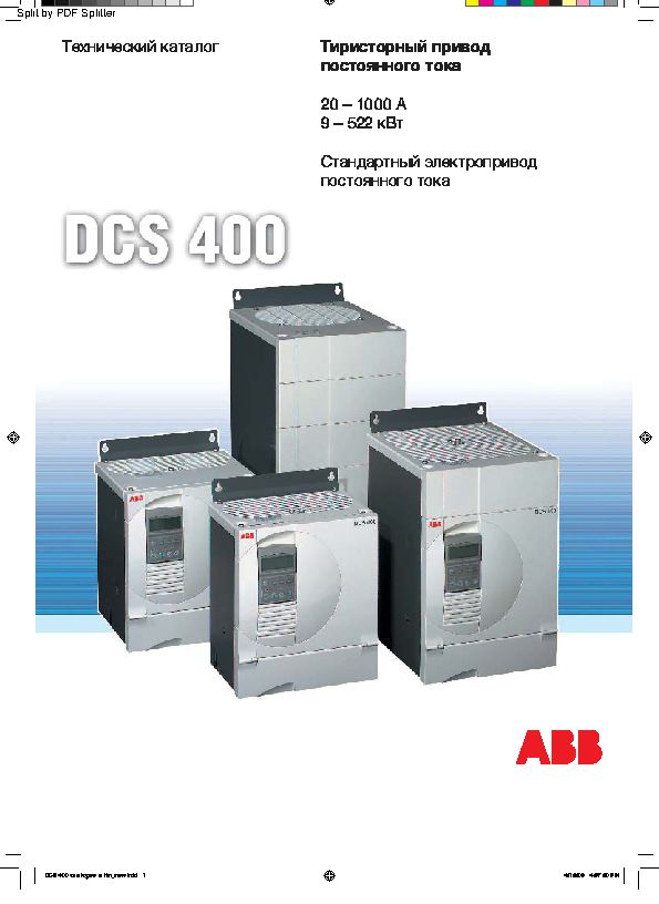
Цифровые электроприводы постоянного тока ABB серии DCS400 является первым полноценным поколением электроприводов постоянного тока на мировом рынке. До монета выхода на рынок цифрового электропривода DCS400 ни один из производителей не мог предложить законченное функциональное решения для управления электромашинами постоянного тока малой и средней мощности. По своим функциональным возможностям, простоте ввода в эксплуатацию с DCS400 не мог конкурировать ни Siemens c приводами Simoreg DC Master, ни Control Techniques с приводами Mentor 2, ни SSD Drives с приводами DC590+.
При проектировании нового поколения приводов компания ABB в первую очередь постаралась уделить внимание созданию человеко-ориентированного оборудования — при настройке пользователь не должен проводить каких-либо дополнительных расчетов, переводя в двоичный код параметры электромашин, не должен собирать дополнительные цепи для проведения оптимизации работы.
Наше знакомство с электроприводом постоянного тока DCS400 произошло в начале 2000-х годов, когда наши инженеры принимали участие в пусконаладочных работах, данными электроприводами комплектовались кутеры CFS, экструдеры Сincinnati, Maillefer, бумагоделательные машины BHS, горнолыжные подъемники.
На протяжении десятилетия наши инженеры эксплуатировали данное поколение электропривода и готовы дать свою оценку его характеристикам.
По нашему мнению электропривод DCS400 обладает лучшей среди DC электроприводов направляемой автонастройкой, позволяющей максимально быстро настроить оборудование под требуемые режимы работы и параметры электродвигателя, дает пользователю возможность многосторонней защиты всего электропривода. Электропривод DCS400 обеспечивает:
- контроль обрыва в цепи обратной связи по скорости,
- защиту электродвигателя от перегрева с помощью PTC-датчиков,
- контроль квадратичной нагрузки;
- контроль превышения заданной скорости;
- защиту от заклинивания вала электродвигателя;
- контроль тока цепи якоря и возбуждения.
В настоящий момент времени приводы серии DCS400 снимаются с производства, «правоприемником» является новая серия цифровых тиристорных регуляторов DCS550.
При выходе из строя ранее установленных приводов серии DCS400 наши инженеры готовы осуществить либо их ремонт, либо осуществить поставку новых приводов DCS550 с проведением предварительного параметрирования, которое позволит вам подключить новый регулятор на прежнее место без дополнительного вмешательства.
Номинальные характеристики цифровых приводов постоянного тока ABB серии DCS400
Входное напряжение питания электропривода 3×220-500В±10% 50Гц
|
Наименование привода |
Параметры привода |
|||
|
нереверсивный |
реверсивный |
Ia, А |
Iexc, А |
Pn, кВт |
|
DCS401.0020 |
DCS402.0025 |
20 / 25 |
4 |
9 |
|
DCS401.0045 |
DCS402.0050 |
45 / 50 |
6 |
21 |
|
DCS401.0065 |
DCS402.0075 |
65 / 75 |
6 |
31 |
|
DCS401.0090 |
DCS402.0100 |
90 / 100 |
6 |
41 |
|
DCS401.0125 |
DCS402.0140 |
125 / 140 |
6 |
58 |
|
DCS401.0180 |
DCS402.0200 |
180 / 200 |
16 |
83 |
|
DCS401.0230 |
DCS402.0260 |
230 / 260 |
16 |
107 |
|
DCS401.0315 |
DCS402.0350 |
315 / 350 |
16 |
145 |
|
DCS401.0405 |
DCS402.0450 |
405 / 450 |
16 |
187 |
|
DCS401.0500 |
DCS402.0550 |
500 / 550 |
16 |
232 |
|
DCS401.0610 |
DCS402.0680 |
610 / 680 |
20 |
282 |
|
DCS401.0740 |
DCS402.0820 |
740 / 820 |
20 |
340 |
|
DCS401.0900 |
DCS402.1000 |
900 / 1000 |
20 |
415 |
Ia – номинальный выходной ток привода, Iexc – номинальный ток цепи возбуждения, Pn – номинальная мощность электропривода.
Тиристорные преобразователи АВВ DCS400: технические характеристики, преимущества, сфера применения
Производственная компания АВВ за годы своего существования на российском рынке электротехники и продукции, созданной для автоматизации производственной деятельности, успела заслужить всеобщее признание и доверие. Основные резервы производства фирмы расположены в крупнейших странах Европы и в России, а потому нашим соотечественникам не придется заказывать высококачественную продукцию издалека.
Технические характеристики
Стандартный тиристорный преобразователь АВВ DCS400 – это современное устройство, созданное для обеспечения бесперебойной работы электрооборудования, мощность которого не превышает 522 кВт.
Главными техническими особенностями являются:
- наличие регулятора скорости работы двигателя в двух направлениях (для ускорения и замедления);
- возможность задавать крутящий момент;
- можно регулировать подачу тока;
- возможность автоматически оптимизировать подачу тока в якорной цепи и других рабочих узлах;
- наличие дистанционного управления током;
- регулятор постоянного тока автоматически контролирует работу системы, предотвращая перегрузки;
- устройство имеет степень защиты IP00;
- есть 3 аналоговых входа и 2 выхода.
Особенности работы механизма
Съемная панель управления, на которой в обычном режиме отображается вся важная информация, помогает быстро выявлять и устранять неисправности в оборудовании. С помощью встроенного возбудителя можно запускать работу механизма без подключения дросселей, предохранителей и дополнительного трансформатора.
Перед началом работы тиристорный преобразователь автоматически получит сведения о подключаемом к нему устройстве и согласует важные параметры. Пакет инструкций поможет пользователю начать эксплуатацию устройства сразу после установки и решать любые трудности, возникающие в процессе работы, с помощью подсказок интерактивного меню.
Преимущества продукции
Тиристорный преобразователь АВВ DCS400 является самым компактным прибором в своем классе. Его легко монтировать, для эксплуатации не требуется прохождение специального курса обучения. Наладить работу устройства поможет интерактивный помощник, встроенный в панель управления. Наличие прикладных макросов обеспечит стабильную, бесперебойную работу всех систем и устройств рабочей цепи.
Сфера применения
Данный преобразователь постоянного тока применяется для обеспечения работы экструдеров, миксеров, куттеров, волочильных машин, прессов и прочего подобного электрооборудования.