
- Печать
Страницы: 1 … 6 7 [8] Вниз

Тема: ARL-200/300/500 (Прочитано 43649 раз)
0 Пользователей и 1 Гость просматривают эту тему.
Есть специальная программка Shafferbox setup en V13

Записан
Игрушка не предназначена для детей школьного возраста. Может содержать мелкие части которые ребенок может проглотить. Перед покупкой убедитесь, что ваш ребенок уже умеет читать.
всем спасибо. В личку прислали английскую версию
Записан
Здравствуйте. Привод ADrive (станция на ARL-300) при включении выдаёт error 2 (low dc bus). Напряжения на клеммах частотника в норме, 380 и 24. Режим эвакуации не включается.
Лифт с монтажа, ездил на ревизии, после месячного простоя такая история случилась. Прошу помощи
Записан
low dc bus
— низкое напряжение на шине постоянного тока. Чаще всего это свидетельствует о большом отборе мощности с шины постоянного тока: например механически заблокирован ротор электродвигателя, либо пробой силового модуля IGBT в частотном преобразователе. Мультиметром в положении «проверка диодов» прозвонить клеммы U,V,W относительно DC+, DC- в прямой и обратной полярности. Коротких замыканий быть не должно, только значение падения напряжения диодов.
Записан

спасибо
Неисправность трёхфазного выпрямительного модуля. В А-Драйвах он выполнен отдельно, замена вполне адекватна по цене.Выходит из строя при неисправности вентиляторов охлаждения и при перекосе фаз (резкие броски по одной из фаз).На моделях В (7.5 и 11 кВт) придется менять термопасту на мосте и IGBT, на моделях С (15 и 22 кВт) мост стоит отдельно и отличается формфактором, обязательно проверяйте по посадочным местам и маркировке -были случаи несовпадения.
Записан
спасибо
Неисправность трёхфазного выпрямительного модуля.
Мост целый dc+ dc- 580v. частотник, как я понял, при первом включении в ошибку впал. Забрал в лабораторию для детального анализа.
Записан
Добрый день. Не могу подобрать PUK код для контроллера arl 300 sn 30-4426 v.3.13. не могли бы мне помочь в данной ситуации, лифт встал не могу зайти в меню, кто то заблокировал лифт до меня. Надеюсь на вашу поддержку, спасибо.
Записан
А зачем подбирать? Пишите письмо по адресу support@arkel.com.tr на английском приблизительно такого текста:
Can you please send me the PUK for Arkel 300, sn 30-4426. Thank you in advance. Regards, Имя, Фамилия
и получаете ответ в течении одного рабочего дня.
Записан
Никогда не сдавайся.
Добрый день. Не могу подобрать PUK код для контроллера arl 300 sn 30-4426 v.3.13. не могли бы мне помочь в данной ситуации, лифт встал не могу зайти в меню, кто то заблокировал лифт до меня. Надеюсь на вашу поддержку, спасибо.
Все большое спасибо за поддержку. Все получилось. Особенная благодарность Ивану vakhter.
Записан
Подскажите пожалуйста, за что отвечают провода S1A, S1B идущие с крыши кабины (плата FX-SERI V3.61) в станцию. Плата ARL-300. Не CAN шина случаем по которой приказы отправляются?
« Последнее редактирование: Август 15, 2020, 17:07:52 от Виталий. »
Записан
Добрый день, пожалуйста помогите советом. Турецкий лифт YUKSELIS ARL-300+Adrive 7,5kw (безмашинка), при торможении на вызванном этаже, например 6, за несколько секунд до открытия дверей внезапно отображает 7,8 и показание остается таким пока не вернется на первый этаж. При вызове с других этажей например с 5го, лифт открывается на 3 этаже соответственно. Замена модуля Encabit plus не помогла. ARL-300 при этом ошибок не выдает. При поездки от первого до последнего этажей все этажи читаются нормально. Проблема возникает при торможении на некоторых этажах. Буду рад если посоветуете где искать неисправность…
Записан
спасибо
Была похожая проблема именно при торможении. Решилось подключением заземления
Записан
спасибо
Спаисбо, Виталий. Сегодня буду проверять подключив заземление и отпишусь. Есть еще подозрение на тормозной резистор, до начала проблемы в резистор попал мусор из-за чего он сильно нагрелся и сработало отключение автомата электричества. Резистор почистили, контакты перепроверили, работает нормально. Может ли он создавать помехи/короткие замыкания и вызвать мою проблему?
Удалено цитирование предыдущего сообщения.
« Последнее редактирование: Ноябрь 14, 2020, 09:31:51 от Мишаня »
Записан
Была похожая проблема именно при торможении. Решилось подключением заземления
Добрый день, заземление не помогло… Где еще искать проблему?
Записан
- Печать
Страницы: 1 … 6 7 [8] Вверх
-
ARL-300 LIFT CONTROLLER
USER MANUAL
-
www.arkel.com.tr
ARKEL 2011 ARL-300 2
Publisher ARKEL Elektrik Elektronik Ticaret Ltd. ti.
erifali Mah. Bayraktar Bulvar Sehit Sk. No:32 Umraniye Istanbul
TURKIYETEL: (+90 216) 540 03 10 11 — 12
Fax: (+90 216) 540 03 09
E-mail : [email protected]
www.arkel.com.tr
Date of issue 2011
Document version V1.9 Hardware version V2.1 Software version
V2.14 -
www.arkel.com.tr
ARKEL 2011 ARL-300 3
CONTENTS INTRODUCTION
………………………………………………………………………………………………………………………………………..
51. LCD SCREEN AND KEYPAD USAGE
………………………………………………………………………………………………………
6STARTUP SCREEN
……………………………………………………………………………………………………………………………………
6MAIN SCREEN
………………………………………………………………………………………………………………………………………….
6ENTERING MENU
…………………………………………………………………………………………………………………………………….
6EXIT FROM MENU
……………………………………………………………………………………………………………………………………
6LCD CONTRAST SETTING SCREEN
…………………………………………………………………………………………………………
7GROUP STATUS SCREEN
…………………………………………………………………………………………………………………………
7MANUAL MOVEMENT SCREEN
………………………………………………………………………………………………………………
7CALL SETTTING SCREEN
………………………………………………………………………………………………………………………..
7RANDOM CALL SCREEN
…………………………………………………………………………………………………………………………
72. LIST OF PARAMETERS
…………………………………………………………………………………………………………………………..
8LISAN/LANGUAGE
………………………………………………………………………………………………………………………………….
9LIFT TYPE
………………………………………………………………………………………………………………………………………………..
9NUMBER OF FLOORS
………………………………………………………………………………………………………………………………
9COMMAND TYPE
…………………………………………………………………………………………………………………………………….
9CAR CALLS FROM
………………………………………………………………………………………………………………………………….
10DOOR TYPE
……………………………………………………………………………………………………………………………………………
10DOOR COMMANDS
………………………………………………………………………………………………………………………………..
10A.DOOR AT FLOOR
………………………………………………………………………………………………………………………………..
10WAITS AT FLOOR
…………………………………………………………………………………………………………………………………..
11DOOR LOCK WAIT
…………………………………………………………………………………………………………………………………
11DOOR OPEN ERROR
……………………………………………………………………………………………………………………………….
11PHOTOCELL TIME
………………………………………………………………………………………………………………………………….
11CAR LIGHT DELAY
………………………………………………………………………………………………………………………………..
11PARK FLOOR
………………………………………………………………………………………………………………………………………….
12PARKING TIME
………………………………………………………………………………………………………………………………………
12FIRE PARK FLOOR
…………………………………………………………………………………………………………………………………
12MOTOR STAR TIME
……………………………………………………………………………………………………………………………….
12STAR/DELTA DELAY
……………………………………………………………………………………………………………………………..
12MOTOR STOP DELAY
…………………………………………………………………………………………………………………………….
13VALVE DROP DELAY
…………………………………………………………………………………………………………………………….
13CONTACTOR DELAY
……………………………………………………………………………………………………………………………..
13MAX FLOOR TO FLR
………………………………………………………………………………………………………………………………
13MAX LOW SPEED T
………………………………………………………………………………………………………………………………..
13DOOR PRE OPENING
………………………………………………………………………………………………………………………………
13RELEVELING
………………………………………………………………………………………………………………………………………….
13BATTERY RESCUE
…………………………………………………………………………………………………………………………………
14DISPLAY SETUP
……………………………………………………………………………………………………………………………………..
14FX_SERI A,B,C,..
……………………………………………………………………………………………………………………………………..
15PT0-PT3 OUTPUT
……………………………………………………………………………………………………………………………………
15BINARY/GRAY CODE
…………………………………………………………………………………………………………………………….
15PR RELAY FUNC.
……………………………………………………………………………………………………………………………………
15GONG OUTPUT
………………………………………………………………………………………………………………………………………
16RST PHASE CHECK
………………………………………………………………………………………………………………………………..
16FAULT LIST
……………………………………………………………………………………………………………………………………………
16ERASE FAULT LIST
………………………………………………………………………………………………………………………………..
16LIMITS AT INSP.
……………………………………………………………………………………………………………………………………..
16FUNCTION OF 120
…………………………………………………………………………………………………………………………………..
16POSITION RESET
……………………………………………………………………………………………………………………………………
17EXT.SAFETY RELAY
………………………………………………………………………………………………………………………………
17GROUP ID
……………………………………………………………………………………………………………………………………………….
17SERVICE TIME
……………………………………………………………………………………………………………………………………….
17END OF SERV TIME
………………………………………………………………………………………………………………………………..
17FIRST STOP
…………………………………………………………………………………………………………………………………………….
17LAST STOP
……………………………………………………………………………………………………………………………………………..
18VATMAN CALLS
……………………………………………………………………………………………………………………………………
18EVACUATION FLOOR
……………………………………………………………………………………………………………………………
18DIRECTION ARROWS
…………………………………………………………………………………………………………………………….
18 -
www.arkel.com.tr
ARKEL 2011 ARL-300 4
PASSWORD
…………………………………………………………………………………………………………………………………………….
19EXIT FROM MENU
………………………………………………………………………………………………………………………………….
193. ARL-300 ERROR CODES
……………………………………………………………………………………………………………………….
204. LEDS AND JUMPERS ON ARL-300 BOARD
………………………………………………………………………………………….
215. FX_SERI SERAL CAR COMMUNCATON BOARD
……………………………………………………………………………
226. FX_SERI_32 SERAL CAR COMMUNCATON AND CALL INPUT BOARD
………………………………………. 227. ARL-SARJ CHARGE
CONTROLLER
…………………………………………………………………………………………………….
238. LEVELED INDICATOR BOARD
…………………………………………………………………………………………………………….
249. INSTALLATION OF MAGNETIC SWITCHES AND MAGNETS
……………………………………………………………
259.1 INSTALLATION AND CONNECTION FOR M1 COUNTER
………………………………………………………………….
269.2. INSTALLATION AND CONNECTION FOR ML1-ML2 COUNTER
……………………………………………………….
2610. CONNECTION OF TOP & BOTTOM LIMIT SWITCHES
…………………………………………………………………….
3010.1. USING SPOOL SWITCHES
………………………………………………………………………………………………………………
3010.2. USING BI-STABLE MAGNETIC SWITCHES
…………………………………………………………………………………….
3111. DOOR BRIDGING SAFETY CIRCUIT
………………………………………………………………………………………………….
3211.1. DOOR BRIDGING PRINCIPLE
…………………………………………………………………………………………………………
3312. GROUP OPERATION
……………………………………………………………………………………………………………………………
3413. DIMENSIONS OF ARL-300 CONTROLLER
…………………………………………………………………………………………
3514. ARL-300 TERMINALS & PLUGS
………………………………………………………………………………………………………….
3614.1. COMMON TERMINALS ON ARL-300 CONTROLLER
………………………………………………………………………………….
3614.2. RELAY OUTPUT TERMINALS ACCORDING TO DRIVE
TYPE………………………………………………………………………..
3714.3. TERMINALS & PLUGS ON KBK4 CONNECTION BOARD
……………………………………………………………………………
3814.4. TERMINALS & PLUGS ON KBK2 CONNECTION BOARD
……………………………………………………………………………
3915. GENERAL SAFETY REGULATIONS
…………………………………………………………………………………………………..
39 -
www.arkel.com.tr
ARKEL 2011 ARL-300 5
INTRODUCTION ARL-300 fulfills the requirements of Europian
electric and hydraulic lifts directive EN81-1/2. ARL-300 is
universal. With just a few parameter changes; it can be used for
hydraulic elevators or rope traction with two-speed or VVVF (geared
and gearless drive), up to 24 stops, and for groups of up to 4
elevators up to 2m/s speed. Most of the functions needed for any
elevator system are integrated into the ARL-300 lift
controller:— Door-bridging safety relays in case of door pre-opening and
re-leveling, — Single automatic door support, — Mains phase
protection, — Motor temperature monitoring, — Binary, inverted
Binary, Gray and inverted Gray code outputs for LCD and Dot-matrix
indicatorsARL-300 is compitable with the serial car communication board
FX-SERI (up to 16 stops) and FX-SERI-32 (up to 24 stops) which
reduces labour and cable costs. KBK connection boards are used with
ARL-300 which are used instead of panel rail terminals and supplied
with ribbon cables. ARL-300 provides emergency rescue operations
for electric (geared and gearless drive) and hydraulic elevators.
Technical Data Description ValueDimensions Length width height
260 200 35
Working temperature 0 — +60 C Degree of protection IP20 Supply
voltage 24 VDC 5 Vdc Control inputs 24 VDC(High active) Control outputs 24 VDC
Short-circuit protected Safety circuit voltage Maksimum voltage
230VAC(24VDC for emergency lowering with Hydraulic systems !!!)
-
www.arkel.com.tr
ARKEL 2011 ARL-300 6
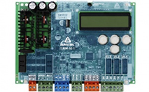
1. LCD SCREEN AND KEYPAD USAGE ARL-300 has an LCD screen with
2-row and 16-character and 4-key keypad.STARTUP SCREEN
When system is energized for the first time or restarted the
SPLASH SCREEN appears. After being displayed this screen for about
3 seconds, MAIN SCREEN is displayed.MAIN SCREEN
The main screen shows the important lift parameters, 100 (Supply
Voltage) and FLOOR (floor number).ENTERING MENU
In order to enter MENU SCREEN, push and hold the LEFT button for
3 seconds. If there is no password has been entered before (0000:
factory default) the first parameter LISAN/LANGUAGE is displayed on
LCD.If a password has been assigned before, you must enter the four
digit password by pressing the UP and DOWN buttons. Then press the
RIGHT button. The first parameter is displayed. If the password is
enteredincorrectly an error massage INVALID PASSWORD will appear on the
LCD. If the password is entered incorrectly for three times, the
system gets blocked and it is required to enter the PUK CODE. You
can pass through the parameters by pressing LEFT and RIGHT buttons
and change the parameters by pressing UP and DOWN buttons. When you
change a parameter by pressing UP and DOWN buttons, the new value
for that parameter is recorded in the temporary memory. It is not
necessary to press any key to record any changed parameter. All
parameters are recorded to the memory after leaving the program
menu. If the power off the controller is turned off and on again
before leaving the program menu, the parameters keep the older
values.EXIT FROM MENU
In order to exit from the MENU SCREEN, first push the RIGHT
button until the EXIT SCREEN is displayed. When this screen is
displayed push UP button to exit from the menu.2-row 16-character LCD screen
ARL-300 V1.4x SERI NO : 36-0298
WAITS FOR CALL 100: 24V FLOOR: 1
LISAN/LANGUAGE ENGLISH
ENTER PASSWORD 0000
EXIT FROM MENU
-
www.arkel.com.tr
ARKEL 2011 ARL-300 7
LCD CONTRAST SETTING SCREEN
LCD display contrast can be adjusted by this screen. In order to
enter this screen, press UP or DOWN keys while on main screen. UP
key is used to increase and DOWN key is used to decrease the LCD
contrastvalue. x signs are used to show the contrast value. After
adjusting contrast value, entering menu is required for once in
order to save this setting. Otherwise when the power turns off,
controller will lose the changes.GROUP STATUS SCREEN
In order to enter this screen press LEFT button while on main
screen. The working status of 4 lifts in a group operation are
displayed on in this screenA, B, C, D : The GROUP ID is defined for controllers in a group
operation +, — : Indicates the controllers status in a group
operation while controller is in group communication [ ] : The own
GROUP ID of the controller — : Indicates the controllers which are
not in a group operation or not definedMANUAL MOVEMENT SCREEN
In order to enter this screen, push and hold the RIGHT button
for 3 seconds. UP and DOWN buttons are used for running UP and DOWN
while in this screen. Press also the RIGHT button together for
runningwith fast speed. Press LEFT button to exit this screen. CALL
SETTTING SCREENIn order to enter this screen, move with LEFT button while on
main screen. Press UP and DOWN buttons to designate the call and
press RIGHT button to activate the call.RANDOM CALL SCREEN
It is possible to give random calls by using this screen. In
order to enter this screen, move with LEFT button while on main
screen. Controller generates a random call by pressing the UP
button while on this screen.This call is displayed in the first line. After giving the first
random call, press UP / DOWN buttons to designate the number of
random calls. The number of random calls is displayed in the second
line. The number of random calls is automatically decreased as the
calls are acknowledged. Press LEFT button to exit this screen.KONTRAST xxxxxxx
GROUP STATUS [A+] B- — —
MANUAL MOVMENT 100:24V FLOOR: 1
CALL SET : 1 ACTIVE CALL : —
RANDOM CALL : — REMAINING :
-
www.arkel.com.tr
ARKEL 2011 ARL-300 8
2. LIST OF PARAMETERS The list of parameters in ARL-300 menu are
listed below: LISAN/LANGUAGE LIFT TYPE NUMBER OF FLOORS COMMAND
TYPE CAR CALLS FROM DOOR TYPE DOOR COMMANDS A.DOOR AT FLOOR WAITS
AT FLOOR DOOR LOCK WAIT DOOR OPEN ERROR PHOTOCELL TIME CAR LIGHT
DELAY PARK FLOOR PARKING TIME FIRE PARK FLOOR FIREMAN MODE MOTOR
STAR TIME (for Hydraulic lifts) STAR/DELTA DELAY (for Hydraulic
lifts) MOTOR STOP DELAY (for Hydraulic lifts) VALVE DROP DELAY (for
Hydraulic lifts) CONTACTOR DELAY (for VVVF rope lifts) MAX FLOOR TO
FLR MAX LOW SPEED T. DOOR PRE OPENING (for Hydraulic and VVVF rope
lifts) RELEVELING (for Hydraulic lifts) BATTERY RESCUE (for
Hydraulic lifts) RESCUE TYPE (for VVVF rope lifts) DISPLAY SETUP
FX_SERI A,B,C,.. PT0-PT3 OUTPUT BINARY/GRAY CODE PR RELAY FUNC.
GONG OUTPUT RST PHASE CHECK FAULT LIST ERASE FAULT LIST LIMITS AT
INSP. FUNCTION OF 120 POSITION RESET EXT.SAFETY RELAY (for
Hydraulic lifts) GROUP ID SERVICE TIME END OF SERV. TIME FIRST STOP
LAST STOP VATMAN CALLS EVACUATION FLOOR MAX.CAR CALLS DIRECTION
ARROWS PASSWORD EXIT FROM MENU -
www.arkel.com.tr
ARKEL 2011 ARL-300 9
This parameter stores the language of the menu.
TRKE: Turkish ENGLISH: English NEDERLANDS: Dutch ROMANA: Romany
P: Russian DUITS: Germany ITALIANO: Italian5 language options can be selected in the menu at the same time.
ARL-300 menu languages are divided into 2 language groups. These
language options are:1st group: Turkish, English, Duits, Dutch and Russian 2nd group:
Turkish, English, Duits, Romany and ItalianThis parameter stores the drive type of lift.
HYDRAULIC 2 SPEED ROPED L. VVVF ROPED LIFT
For VVVF roped lifts (geared and gearless drive) also the
parameter RESCUE TYPE must be set according to the system.This parameter stores the number of stops in lift system from 2
to 24.2-24 stops
This parameter stores the lift command type.
SIMPLE COLLECTVE : Car and landing call buttons are tied
together. There is no difference between car and landing calls. 1
BUTTON UP&DOWN : Car and landing call buttons are connected
separately. Car calls and landing calls are collective in both
directions. 1 BUTTON DOWN : Car and landing call buttons are
connected separately. Car calls are collective in both directions
where landing calls are collective when the lift moves downwards. 1
BUTTON UP : Car and landing call buttons are connected separately.
Car calls are collective in both directions where landing calls are
collective when the lift moves upwards. 2 BUTTON SEL.COL : Car,
landing up and landing down buttons all are connected separately.
Car and landing call are all serviced in full collective manner.
UNIVERSAL : Non-collective system. Car and landing call buttons are
tied together.LISAN/LANGUAGE
LIFT TYPE
NUMBER OF FLOORS
COMMAND TYPE
-
www.arkel.com.tr
ARKEL 2011 ARL-300 10
This parameter determines the communication between controller
and car.MAINBOARD : Parallel connection is used between controller and
car. There is no serial communication board (FX_SERI) used in
inspection box.SERIAL E.CARD 16 : The serial communication board FX-SERI-16 is
used in inspection box for connection between lift controller and
car for up to 16 stops. Landing panels are connected as in parallel
mode.SERIAL E.CARD 32 : The serial communication board FX-SERI-32 is
used in inspection box for connection between lift controller and
car for more than 16 stops. Landing panels are connected as in
parallel mode.For systems with more than 16 stops, it is required to use
serial car installation in ARL-300 control system. FX_SERI_32 board
must be used both in inspection box and in control panel.This parameter stores the type of automatic door.
ONLY CAR DOOR : Semi-automatic landing door and automatic car
door FULL AUTOMATIC : Full-automatic car and landing door.Automatic door open-close signal type.
CLOSE SIGNAL: When only a door close signal is used. Door is
closed when the door close signal is ON and door is open when the
door close signal is removed. When 120 signal (stop circuit) is
OFF, door remains close. OPEN/CLOSE SGNL: Door open signal and door
close signals are used. Door is closed when the door close signal
is ON. Door is open when the door open signal is ON. Door remains
its position when there is no door signal ON. When 120 signal (stop
circuit) is OFF, none of the door signals are activated.According to the EN81-1/2, door movement must be prevented when
emergency stop, inspection or recall modes engaged.Automatic door position when lift waits at floor level.
WAITS CLOSED : Waits with closed door. WAITS OPEN : Waits with
open door. (Not in conformity with EN81-1/2)Waits open is not allowed according to the standard EN 81-1/2.
So this parameter must be set to Waits closed to fully fit
EN81-1/2. The lifts at the countries which has own standard other
then EN81-2/2 or at the lifts that modernized and taken measures
against risk of doors waiting open can be set as Waits open.CAR CALLS FROM
DOOR TYPE
DOOR COMMANDS
A.DOOR AT FLOOR
-
www.arkel.com.tr
ARKEL 2011 ARL-300 11
This parameter stores the time period for car to wait at floor
before moving for the next call in collective systems.0 to 60 seconds
If a serial communication board (FX-SERI) is used in inspection
box and the OPEN/CLOSE button signals are connected to serial
communication board, this parameter should be increased.According to the EN81-1/2for semi-automatic doors, car must wait
at least 2 seconds at floor before moving again.For non-collective systems, the parameters WAITS AT FLOOR and
CAR LIGHT DELAY should be set to same value and must be set to at
least 2 seconds.This parameter stores the maximum time period to wait for door
lock signal (140) after door close signal comes to controller.10 to 99 seconds Set this parameter to 35 s for semi-automatic
doors and 95 s for full automatic doors.At the end of this time period if doors still cannot be closed,
controller gives an error and goes out of service.10 to 240 seconds DISABLED: Door open error function is
disabled.Set this parameter to 240 s for full automatic doors.
This parameter stores the photocell time.
0 to 60 seconds
This parameter determines the car light delay time.
DISABLED : Car light delay is disabled (Not in conformity with
EN 81-1/2 for semi-automatic doors) 1 to 240 secondsAccording to the EN 81-1/2 turning off car light delay is not
allowed for semi-automatic doors.For non-collective systems, the parameters WAITS AT FLOOR and
CAR LIGHT DELAY should be set to same value and must be set to at
least 2 seconds.WAITS AT FLOOR
DOOR LOCK WAIT
DOOR OPEN ERROR
PHOTOCELL TIME
CAR LIGHT DELAY
-
www.arkel.com.tr
ARKEL 2011 ARL-300 12
This parameter defines the parking floor.
DISABLED : Parking floor is disabled. 1 to 24 : The parking
floor of the elevator.When parking floor is not disabled and lift has no calls within
this time, it moves to parking floor and stays there until a call
comes.0 to 250 seconds
Fire parking floor number. When the fire input of the lift
(terminal YAN) is activated then the car immediately moves to this
floor and waits there with open doors. The elevator returns to
normal operationafter the fire signal is deactivated. DISABLED : Fire parking
floor is disabled. 1 to 24: The fire parking floor of the
elevator.If the elevator serves as a fire-fighters lift then this
parameter should be enabled.DISABLED : Fire-fighters mode is disabled. ENABLED :
Fire-fighters mode is enabled.In ARL-300 system, the fire-fighters mode is only available with
serial car installation. Theinput terminals 804, K20 ve DTS are used for connection of the
signals required in fire-fighters mode. 804: Fire-fighters key
switch input K20: Door is fully open contact input DTS: Door is
fully closed contact input The contacts used for door open and
closed limits must be normally closed contacts. When door is fully
open/closed these signals must be turned off.This parameter determines the switching time of the motor from
star connection to delta connection in startup. (For hydraulic
systems)0.0 to 9.9 seconds
This parameter determines the time to wait after finished the
star connection and will start the delta connection. (For hydraulic
systems)0.0 to 9.9 seconds
PARK FLOOR
PARKING TIME
FIRE PARK FLOOR
FIREMAN MODE
MOTOR STAR TIME
STAR/DELTA DELAY
-
www.arkel.com.tr
ARKEL 2011 ARL-300 13
This parameter determines the delay time for main contactor to
drop after a stop command. (For hydraulic systems)0.0 to 9.9 seconds
This parameter determines the delay time for valves to drop
after a stop command. (For hydraulic systems)0.0 to 9.9 seconds
The time to keep the main contactor switch on after the movement
ends can be adjusted by this parameter. (For VVVF roped lifts)0.0 to 9.9 seconds
This parameter stores the maximum time allowed to pass without
changing the current floor number.5 to 120 seconds
According to the EN81-1/2, the motor run time limiter shall
function in a time which does not exceed the smaller of the
following two values:a) 45 s b) time for travelling the full travel with rated load,
plus 10 s, with a minimum of 20 s if the full travel time is less
than 10 s.This parameter stores the maximum time allowed to reach the
floor level after passing to low speed.5 to 60 seconds
This parameter determines the activation of door pre-opening
(for Hydraulic and VVVF rope lifts).DISABLED : Door pre-opening is disabled. ENABLED : Door
pre-opening is enabled.This parameter determines the activation of releveling for
hydraulic systems (for Hydraulic and VVVF rope lifts).DISABLED : Releveling is disabled. ENABLED : Releveling is
enabled.MOTOR STOP DELAY
VALVE DROP DELAY
CONTACTOR DELAY
MAX FLOOR TO FLR
MAX LOW SPEED T
DOOR PRE OPENING
RELEVELING
-
www.arkel.com.tr
ARKEL 2011 ARL-300 14
This parameter determines the activation of the emergency
battery lowering for hydraulic systems. (for Hydraulic lifts).DISABLED : Emergency battery lowering is disabled. ENABLED :
Emergency battery lowering is enabled.The rescue type of the system for VVVF rope lifts (geared and
gearless drive).EXTERNAL OR NONE : This option should be selected for geared
asynchronous machines. BRAKE RELEASE: This option should be
selected for gearless synchronous machines when the evacuation
process is done by ARL-300 with releasing the brakes. DRIVE WITH
VVVF : This option should be selected for gearless synchronous
machines when the evacuation process is done by inverter with
driving the motor (for evacuation with battery or UPS).The floor settings for 7-segment displays or simple floor
indicators are adjusted with the help of this screen. Press UP
button during in this parameter to enter display setup screen. Then
you can change theblinking parameter by pushing UP/DOWN buttons. Use LETF/RIGHT
buttons for selecting floor number and its display setup. The
display setup can be entered for each floor separately. The floor
texts can be selected for 7-segment displays and the output signals
can be selected for simple floor indicators in ARL-300 menu are
listed below: Display type Options7-segment -9, -8, -7, -6, -5, -4, -3, -2, -1, 0, 1, 2, 3, 4, 5,
6, 7, 8, 9, 10, 11, 12, 13, 14, 15, 16, 17, 18, 19, 20, 21, 22, 23,
24, 25, 26, 27, 28, 29, A, b, C, d, E, F, H, J, L, n, o, P, u, y,
space, -, =, 1A, 1b, 2A, 2bSimple floor indicator
K1, K2, K3, K4, K5, K6, K7, K8, K9, KX K1: Only A terminal gives
output K2: Only B terminal gives output K8: Only G2 terminal gives
output K9: Only BC terminal gives output KX: All A, B, … , BC
terminals give outputThe outputs A, B, C, D, E, F, G, BC and G2 on KBK-2 connection
board are used for 7-segment displays at landings. In addition to
this, the output 20 on FX_SERI_32 board is used for systems more
than 16 stops. These outputs are also used for 7-segment display in
car when car installation is paralel. The simple floor indicator
signals K1, K2, , K8, K9 are respectively given from A, B, , G2 and
BC outputs (on KBK-2 and FX_SERI boards). For example, when K1
option is assigned for 1st stop, the simple floor indicator signal
for 1st stop will be given from output A.BATTERY RESCUE
RESCUE TYPE
DISPLAY SETUP
-
www.arkel.com.tr
ARKEL 2011 ARL-300 15
When FX_SERI serial communication boards are used, the code type
of display outputs given from A, B, C, terminals on FX_SERI boards
is programmed by this parameter.7 SEGMENT OUTPUT : 7 segment code outputs GRAY CODE OUT : Gray
code outputs BINARY CODE OUT : Binary code outputs INVERTED BINARY
: Inverted binary code outputs INVERTED GRAY C. : Inverted gray
code outputs When display outputs are programmed to binary/gray
code, A, B, C, D and E outputs give gray/binary code signals (M0,
M1, M2, M3 and M4) respectively. Output A is the least significant
bit and B is the most significant bit. Output E is only activated
on FX_SERI_32 board for more than 16 stops. For activating simple
floor indicator outputs this parameter must be se to 7 segment
output. A, B, , G2 and BC outputs give K1, K2, , K8 and K9 signals
respectively.This parameter determines the code type of programmable outputs
(floor position for LCD and Dot Matrix Display).GRAY CODE : Gray code output for position indicators BINARY CODE
: Binary code output for position indicators Programmable outputs
PT0, PT1, PT2 and PT3 on ARL-300 board give gray/binary code
signals (M0, M1, M2 and M3) respectively. PT1output is the least
significant bit and the PT4 is the most significant bit. The
programmable outputs M0-M4 on FX_SERI_32 board are also programmed
with this parameter. These outputs are used for systems more than
16 stops instead of PT1-PT3 outputs on ARL-300 mainboard.This parameter is used to determine the beginning code of
outputs which are programmed to gray/binary code on ARL-300
controller or FX_SERI board.0, 1, 2, 3 : Gray/Binary code outputs start counting from 0 (0
code output for 1st floor ) 15,16,17,18 : Gray/Binary code outputs
start counting from 15 (15 code output for 1st floor )This parameter is used to determine the function of PR
programmable relay output on ARL-300 controller.GONG OUTPUT : Gong output. When serial car connection is used,
terminal DD at FX_SERI board is used as gong output. 2nd MOTOR
CNTRL. : The second motor control output used for releveling of
high power hydraulic systems.FX_SERI A,B,C,..
PT0-PT3 OUTPUT
BINARY/GRAY CODE
PR RELAY FUNC.
-
www.arkel.com.tr
ARKEL 2011 ARL-300 16
This parameter is used to determine the ding-dong timing.
ON DOOR OPENING : Gong signal is activated when the door is
opening. WHEN SLOWING : Gong signal is activated when the car slows
down. WHEN STOPED : Gong signal is activated when the car
stops.This parameter determines the activation of phase order and
phase failure protection.DISABLED : RST phase check is disabled. ENABLED : RST phase
check is enabled.Controller saves the last 60 errors in its memory. By this,
facility for maintenance and reparing is provided. Use UP button to
display the fault list.The list of the faults is displayed on the secreen. Last error
is number 1 and the oldest error is number 60.All faults in the memory are erased. Press UP button and then
press DOWN button to approve erasing fault list.On inspection mode this parameter defines if car stops
immediately after reaching Bottom & Top limit switches or
continue until to the floor level.DIRECT STOP GO FLOOR LEVEL
Set this parameter to GO FLOOR LEVEL for systems with AKUS-SD
evacuation unit.This parameter determines the manner of the controller when 120
signal cut off.STOP ONLY : When 120 signal is cut off, the system is stopped.
After the signal comes back, controller returns to operation. STOP
& BLOCK : When 120 signal is cut off, the system is stopped and
blocked. In order to run the system, controller must be reset.
BLOCK LANDINGS : When 120 signal is cut off, landing calls are
blocked. Elevator returns to normal operation when a car command is
given or when the landing door is opened.GONG OUTPUT
RST PHASE CHECK
FAULT LIST
FAULT NO: 1 H1 H1:FAIL TO LOCK
ERASE FAULT LIST
LIMITS AT INSP.
FUNCTION OF 120
-
www.arkel.com.tr
ARKEL 2011 ARL-300 17
Although the ARL-300 controller remembers the last position at
any mains power failure, controller can reset its position after a
mains failure. This parameter can be set to ENABLED for hydraulic
liftsand rope lifts with AKUS-SD emergency battery leveling device.
So the controller resets its position when mains power is live.DISABLED ENABLED
This parameter determines if there is external safety
relay/contactor used with valves block connection. (for hydraulic
systems)INSTALLED NOT INSTALLED
This parameter determines the GROUP ID of the controller in a
group operation. It can be set as A,B,C and D. Each GROUP ID must
be diffrent in a group operation.CONTROLLER A to D
This parameter is decreased for each day as long as the
controller runs. When this value becomes 0 the elevator behaves as
set in the parameter END OF SERV TIME.0-255 days
The controllers behaviour after the maintenance date is
exceeded.CONTINUE WORKING : No action, even a warning message. Elevator
runs as normal. STOP : Lift is blocked and stop operating waits for
maintenance.This parameter is only used for group operation. When each
elevator has different number of stops in group operation, this
parameter is used to adjust the first stop for the elevator which
has difference. It is required toadjust the NUMBER OF FLOOR parameter to the same value for each
elevator in group. For example, there is a dublex system with 10
stops, but elevator A does not serve to the bottom floor. The
NUMBER OF FLOOR parameter must be set to 10 at each elevator and
FIRST STOP parameter must be set to AT BOTTOM + 1 at only elevator
B. AT BOTTOM FLOOR: This elevator serves to the bottom floor in
group operation. AT BOTTOM + 1: The first stop of this elevator is
1 floor above the bottom floor in group. AT BOTTOM + 2: The first
stop of this elevator is 2 floor above the bottom floor in group.
AT BOTTOM + 3: The first stop of this elevator is 3 floor above the
bottom floor in group.POSITION RESET
EXT.SAFETY RELAY
GROUP ID CONTROLLER A
SERVICE TIME
END OF SERV TIME
FIRST STOP
-
www.arkel.com.tr
ARKEL 2011 ARL-300 18
This parameter is only used for group operation. When each
elevator has different number of stops in group operation, this
parameter is used to adjust the last stop for the elevator which
has difference. It is required toadjust the NUMBER OF FLOOR parameter to the same value for each
elevator in group. For example, there is a dublex system with 10
stops, but elevator A does not serve to the top floor. The NUMBER
OF FLOOR parameter must be set to 10 at each elevator and LAST STOP
parameter must be set to AT TOP FLOOR — 1 at only elevator B. AT
TOP FLOOR: This elevator serves to the top floor in group
operation. AT TOP FLOOR — 1: The last stop of this elevator is 1
floor below the top floor in group. AT TOP FLOOR — 2: The last stop
of this elevator is 2 floors below the top floor in group. AT TOP
FLOOR — 3: The last stop of this elevator is 3 floors below the top
floor in group.This parameter determines the response type of the elevator
during the VATman operation.Single car call: Only one call is active in VATman operation
(Other calls will be canceled). Last car call: The last call will
be active in VATman operation (Other calls will be canceled). Multi
car call: All car calls will be active in VATman operation.The evacuation floor number. When the evacuation function is
enabled, elevator cancels all calls. Stops at nearest floor if it
moves and goes to the evacuation floor. After it comes to the
evacuation floor, itopens door and waits at this floor with open doors. After
waiting 30 seconds, elevator closes the doors and returns to normal
operation. The evacuation function is available only with serial
car installation and it is enabled by using a panic button at car
panel which is connected to the terminal 805 on ARL-300 controller
that is not used when the car communication is serial. DISABLED: If
there is no panic button on car operating panel this function must
be disabled. 1-24: Evacuation floor.This parameter determines the maximum number of car commands.
After reaching this number the car commands will not be
accepted.NO LIMIT: There is no limit for number of car commands. 1-15 :
Maximum number of car commands.The operating type of up and down direction arrows (31 and 32
signals ).RUN DIR+NEXT DIR : When the elevator is running, direction
arrows indicate the running direction. When the elevator waits at
floor, direction arrows indicate the direction of next travel.NEXT DIRECTION : Direction arrows indicate the direction of next
travel when the elevator waits at floor. No indication is given
when the elevator is running.LAST STOP
VATMAN CALLS
EVACUATION FLOOR
MAX.CAR CALLS
DIRECTION ARROWS
-
www.arkel.com.tr
ARKEL 2011 ARL-300 19
The password to enter program parameters menu. Use UP/DOWN
buttons to set the password. Dont forget your password. It will be
asked to enter into the menu next time.In order to exit from the menu, push UP button.
PASSWORD 0000
EXIT FROM MENU
-
www.arkel.com.tr
ARKEL 2011 ARL-300 20
3. ARL-300 ERROR CODES CODE ERROR H1 FAIL TO LOCK DOOR. 140
SIGNAL IS MISSED H2 FLOOR TO FLOOR MAX TRAVEL TIME ELAPSED H3 DOOR
IS NOT CLOSED FOR A LONG TIME H4 MAX SLOW SPEED TRAVEL TIME ELAPSED
H5 BOTH LIMIT SWITCHS UP&DOWN IS OPEN H6 TOP LIMIT SWITCH IS
CUTS OFF WHILE RUNNIG DOWN H7 BOTTOM LIMIT SWITCH IS CUTS OFF WHILE
RUNNIG UP H8 MOTOR PTC CIRCUIT IS OPEN. MOTOR OVER HEAT H9 SYSTEM
ERROR H10 CONTACTOR CHECK BACK ERROR H11 ML1 & ML2 SIGNALS
SHORT CIRCUIT TO EACH OTHER H12 DOOR BRIDGING RELAYS SR2 & SR3
DONT PICK UP H13 DOOR BRIDGING RELAYS SR2 or SR3 DONT DROP H14 DOOR
BRIDGING RELAY SR1 CHECK BACK ERROR H15 RST MAINS POWER SUPPLY
FAILURE H16 24V (100) SUPPLY IS UNDER LIMIT H17 PTC SIGNAL OPEN.
MOTOR OVER HEATED H18 FAULT SIGNAL FROM VVVF DRIVER H19 SAME GROUP
ID NAME USED ON CONTROLLERS H20 120 (STOP) SIGNAL IS MISSING.
ELEVATOR BLOCKED H21 EXTERNAL SAFETY RELAY CHECK BACK ERROR H22
SERVICE TIME OVERFLOW -
www.arkel.com.tr
ARKEL 2011 ARL-300 21
4. LEDs and JUMPERs ON ARL-300 BOARD
-
www.arkel.com.tr
ARKEL 2011 ARL-300 22
5. FX_SERI Serial Car Communication Board FX_SERI is used in
inspection box with systems less than 16 floors for serial car
communication with ARL-300 controllers. Two wires will be enough
and no other installation is needed betwen car and control panel
for car buttons, indicators, over load, full load, gong, direction
arrows, car lamp, automatic door open / close buttons and
inspection operation buttons. The code type of display outputs A,
B, C, on FX_SERI board can be programmed to 7 segment code, gray
code, binary code, inverted gray code or inverted binary code by
the ARL-300 menu.6. FX_SERI_32 Serial Car Communication and Call Input Board
FX_SERI_32 is used with systems more than 16 floors with ARL-300
controllers. It is used in inspection box for serial car connection
and in control panel for call input-output connections with ARL-300
controllers. When it is used in inspection box, two wires will be
enough and no other installation is needed betwen car and control
panel for car buttons, indicators, over load, full load, gong,
direction arrows, car lamp, automatic door open / close buttons and
inspection operation buttons. There are also gray/binary code
outputs M0-M4 at FX_SERI_32 board which can be used for LCD and
Dot-matrix indicators. The code type of outputs can be set by
ARL-300 menu.Output setting of 32 signal
+-
2 jumpers are used for output settings of 31 (Down Arrow
Indicator) and 32 (Up Arrow Indicator) outputs:Plug jumpers to + and middle pins for signal output 100 (+24V)
Plug jumpers to — and middle pins for signal output 1000 (0V)Output setting of 31 signal
Reserved
Setting of the FX_SERI_32 usage
Jumper is used for selecting the usage of FX_SERI_32 board
either for car calls or landing calls:Plug jumper to upper 2 pins in case of using in inspection box
for car calls Plug jumper to lower 2 pins in case of using in
control panel for landing calls -
www.arkel.com.tr
ARKEL 2011 ARL-300 23
7. ARL-SARJ CHARGE CONTROLLER
ARL-SARJ board is used only with Hydraulic lifs. It charges the
batteries (2 x 12V/1.2Ah) used for hydraulic emergeny lowering.
(When mains power is off 24Vdc supply is required for ARL-300
controller and 12Vdc supply is required for safety circuits and for
emergency lowering valve) ARL-SARJ board checks the mains power in
normal operation mode. It charges the batteries and gives the PTC
signal to ARL-300 board according to state of terminals T1-T2 .The processor is working correctly
Mains power is ON Relay is activated Battery charging is
activated -
www.arkel.com.tr
ARKEL 2011 ARL-300 24
8. LEVELED INDICATOR BOARD LEVELED indicator is normally used
with hydraulic systems (Optional with rope lifts). It indicates the
floor level with LEDs on it even the power is off. The board must
also be supplied with a battery when there is no voltage at
terminals 100-1000. After the car is levelled it also sounds an
alert by buzzer. There is also a lamp output (12V/1W) which can be
used to display levelled signal in a different place. The magnetic
switches which will be connected to LEVELED board (SML1-SML2 or
SJF) must also be supplied with the battery (12V) in order to give
signals to LEVELED board even the 24V is off.Levelled indicator
Buzzer for sound alert when car is levelled after evacuation
L+ ve L- output for connection external lamp (12V/1W)
Counter type selection jumper:
For ML1-ML2 counter: ML For M1 or JF counter: 142
Magnetic switch inputs:
For ML1-ML2 counter: SML1 ve SML2 For M1 or JF counter: SJF
Battery connection (BAT+) must be done from inspection box
(12V) -
www.arkel.com.tr
ARKEL 2011 ARL-300 25
9. INSTALLATION OF MAGNETIC SWITCHES AND MAGNETS ARL-300
controller uses two different car positioning system listed below:
Standart M1 counter: Used with two-speed systems ML1-ML2 counter:
Used with VVVF and hydraulic systems The following table shows the
type of magnetic switches required for car positioning:Car position sensing Drive type Door
pre-opening and releveling
Required magnetic switches
Standart M1 counter Two speed NO SM1 (Bi-stable) SJF
(Bi-stable)ML1-ML2 counter VVVF/ Hydraulic YES/NO SML1, SML2
(Mono-stable)SJF1, SJF2 (Mono-stable)
-
www.arkel.com.tr
ARKEL 2011 ARL-300 26
9.1 INSTALLATION AND CONNECTION FOR M1 COUNTER Installation of
magnetic switches and magnets M1 counter positioning requires 2
additional magnetic switches on the car top: 1. Floor counting ve
deceleration magnetic switch (SM1, Bi-stable) 2. Level stopping
magnetic switch (SJF, Bi-stable) Bi-stable magnetic switches and
round magnets are used for this positioning system. SM1 (ML1)
magnetic switch is used for floor counting at the same time for
deceleration of the car. SJF (142) magnetic switch is used for
stopping at floor level.Install the round magnets carefuly according to wiring diagrams
with taking care of the distance between magnets and the pole of
magnets (see sheet 13). Connection of magnetic switches SM1
magnetic switch is connected to terminals ML1-100. SJF magnetic
switch is connected to terminals 142-100. 9.2. INSTALLATION AND
CONNECTION FOR ML1-ML2 COUNTERML1-ML2 counter positioning requires 4 additional magnetic
switches on the car top: 1. Door zone magnetic switches (SML1,
SML2) 2. Travelling magnetic switches (SJF1, SJF2) -
www.arkel.com.tr
ARKEL 2011 ARL-300 27
9.2.1. DOOR ZONE MAGNETIC SWITCHES (SML1, SML2)
1. Door Zone Magnetic Switch-1 (SML1, Monostable, NO-normally
open) 2. Door Zone Magnetic Switch-2 (SML2, Monostable, NO-normally
open)SML1-SML2 magnetic switches inform control panel that the car is
in door opening zone.Installation of magnetic switches Install the SML1-SML2 magnetic
switches on the cage beam in a pre-assembled bracket. SML2magnetic switch must be on top of SML1 and two of them must
observe the same side of guide rail.Connection of magnetic switches SML1-SML2 magnetic switches are
connected to plugs ML1-100 and ML2-100 respectively.Ribbon magnets are used for this positioning system. The length
of the zone magnets are approx. 40cm. The number of zone magnets
are determined by number of floor:Number of ribbon magnets length 40 cm = Number of floor
Installation of zone magnetsMove the car to the end of floors Car threshold must be exactly
at the floor level Install the ribbon magnet opposite to the zone
magnetic switches. The middle of the ribbon magnet must be on a
level with the middle of the magnetic switches. The distance
between magnetic switches and magnet must be 1-2 cm. 40 cm ribbon
magnets must be fixed with screw or glue Repeat this installing
operation at all floors.CAR
FLOOR LEVEL
20cm
20cm
-
www.arkel.com.tr
ARKEL 2011 ARL-300 28
9.2.2. TRAVELLING MAGNETIC SWITCHES (SJF1, SJF2) 1. Downward
travelling magnetic switch (SJF1, Monostable, NO-normally open) 2.
Upward travelling magnetic switch (SJF2, Monostable, NO-normally
open) SJF1 and SJF2 magnetic switches are used to deceleration and
stopping the car depending on the direction of travel. Moreover
they are used to relevelling for hydraulic systems.Installation of magnetic switches Install the SJF1 and SJF2
magnetic switches on the cage beam in a pre-assembled brackets
separately. They must be installed side by side and must observe
the different side of guide rail. Connection of magnetic switches
SJF1 magnetic switch is connected to plugs 141-100. SJF2 magnetic
switch is connected to plugs 142-100.The length of the zone magnets are approx. 10cm. The number of
zone magnets are determined by number of floor and can be
calculated by the following formula:Number of ribbon magnets length 10 cm = (Number of floor x 4)
-2 -
www.arkel.com.tr
ARKEL 2011 ARL-300 29
Installation of travelling magnets There are two types of
travelling ribbon magnets:— Level stopping/relevelling magnetic switches — Deceleration
magnetic switches Level stopping/relevelling ribbon magnetsNote
The 3 cm distance of magnet above/below the magnetic switches is
determined by the need of deceleration distance. It can be
different in any system. It is required that both magnetic switches
observe their magnets at floor level.Deceleration magnets
Note
The deceleration distance is determined by speed of the car. It
can be different in any system and can be accepted 180 cm for VVVF
systems and 60 cm for hydraulic systems.Move the car to the end of floors Car threshold must be exactly
at the floor level Install one of the ribbon magnets length 10cm
opposite to theSJF1 magnetic switch. The middle of the magnetic switch must
observe the ribbon magnet 3 cm above and 7 cm below. The distance
between magnetic switches and magnet must be 1-2 cm.Install the other ribbon magnet length 10cm opposite to the SJF2
magnetic switch. The middle of the magnetic switch must observe the
ribbon magnet 7 cm above and 3 cm below. The distance between
magnetic switches and magnet must be 1-2 cm.Repeat this installing operation at all floors.
Install the ribbon magnet as deceleration distance above the
SJF1 magnetic switch (Excluding the top floor).Install the ribbon magnet as deceleration distance below the
SJF2 magnetic switch (Excluding the bottom floor).Repeat this installing operation at all floors
Down direction stop distance
Up direction stop distance
Up direction deceleration distance
Down direction deceleration distance
-
www.arkel.com.tr
ARKEL 2011 ARL-300 30
10. CONNECTION OF TOP & BOTTOM LIMIT SWITCHES
ARL-300 controller is available with two different top &
bottom limit switch options.Spool switches Bi-stable magnetic switches
10.1. USING SPOOL SWITCHES
Installation and connection of SKSR1 bottom limit switch and
metal plate Move the car to the bottom floor. The bottom limit
switch must be switched off when car is below the bottom floor
level as deceleration distance. It means it must be switched when
down deceleration signal for bottom floor is activated. Install the
spool switch and metal plate according to this need. If the spool
switch is mounted to car, it is connected to terminals 817-100 at
car top. If it is mounted to shaft, it is connected to terminal
817-100 at control panel. Installation and connection of SKSR2 top
limit switch and metal plateMove the car to the top floor. The top limit switch must be
switched off when the car is above thebottom floor level as deceleration distance. It means it must be
switched when up deceleration signal for top floor is activated.
Install the spool switch and metal plate according to this
need.If the spool switch is mounted to car, it is connected to plugs
818-100 at car top. If it is mounted toshaft, it is connected to plugs 818-100 at control panel.
Note
Make the connection of up & down limit switches according to
the wiring diagram (see sheet 8 and 13) -
www.arkel.com.tr
ARKEL 2011 ARL-300 31
10.2. USING BI-STABLE MAGNETIC SWITCHES Installation and
connection of SKSR1 bottom limit switchInstall the SKSR1 bi-stable magnetic switches on the cage beam
in a pre-assembled bracket. SKSR1 magnetic switch is connected to
plugs 817-100. Installation of round magnets for bottom limit
switchInstallation and connection of SKSR1 top limit switch
Install the SKSR2 bi-stable magnetic switches on the cage beam
in a pre-assembled bracket. SKSR2 magnetic switch is connected to
plugs 818-100. Installation of round magnets for top limit
switchMove the car to the bottom floor. Car must be exactly at the
floor levelInstall the round magnet with red color side above the SKSR1
magnetic switch as deceleration distance. It means it must be
switched on when down deceleration signal for bottom floor is
activated.Install the round magnet with black color side a little above
the red color magnet. It means it must be switched off when the car
is out of the bottom limit zone. The distance between magnetic
switch and magnets must be 1-2 cm.Move the car to the bottom floor. Car must be exactly at the
floor levelInstall the round magnet with red color side below the SKSR2
magnetic switch as deceleration distance. It means it must be
switched on when up deceleration signal for bottom floor is
activated.Install the round magnet with black color side a little below
the red color magnet. It means it must be switched off when the car
is out of the top limit zone. The distance between magnetic switch
and magnets must be 1-2 cm.FLOOR LEVEL
Down direction deceleration distance
Red side
Black side
FLOOR LEVEL
Up direction deceleration distance
-
www.arkel.com.tr
ARKEL 2011 ARL-300 32
11. DOOR BRIDGING SAFETY CIRCUIT The door bridging safety
circuit is integrated in the ARL-300 controller board (SR1, SR2,
SR3 safety relays and RBE relay) and enables car movements in the
door zone with open car and landing doors. This makes approaching
and relevelling with open doors possible. The door bridging circiut
requires two magnetic switches on car roof SML1 ( door zone-1) and
SML2 (door zone-2). SML1-SML2 magnetic switches must be installed
in the same pre-assembled bracket and SML2 (door zone-2) magnetic
switch must be on top of SML1 (door zone-1). 40cm ribbon magnets
are used with door zone magnetic switches. The door bridging
operation can only be activated and commissioned if these two
magnetic switches including magnets are installed and connected
(see installation and connection of door zone magnetic
switches).Note
If the two functions Door pre-opening and Hydaulic relevelling
are not required, the door bridging operation is not activated. But
the magnetic switches zone-1 & zone-2 including magnets are
required for ML1-ML2 counter positioning.Warning
According to EN81, the maximum size of the door zone is 400mm
(200mm in each direction). The actual dimensions of the door zone
are forced by the length of the door cam. The distance to the door
zone magnets must not be larger than the length of thedoor cam. Maximum length 40cm. The door zone magnets must be
placed so both magnetic switches are closed in thedoor zone and open outside the door zone.
-
www.arkel.com.tr
ARKEL 2011 ARL-300 33
11.1. DOOR BRIDGING PRINCIPLE The door bridging principle can be
described with the following steps below : The relays SR1, SR2, SR3
and RBE are released in the beginning. If the car approaches the
target floor with a slow speed, safety relay SR1 (starting doorbridging) is activated by the controller. By the way SR2 and SR3
safety relays get ready to be triggered and activated by SR1
safetyrelay when car reaches the door zone. The safety relays SR2 and
SR3 issue the zone message to the controller (car is in door zone).
If the car reaches the door zone, first the magnetic switches of
door zone-1 ( SML1) trigger andactivate the safety relay SR2 (when running downward). After
then the magnetic switches of door zone-2 ( SML2) trigger and
activate the SR3. The safety relay SR1 (starting door bridging) is
released after the SR2 and SR3 relays areactivated. After the control software received the bridging
available message, the enable relay RBE isactivated. These relays state (RBE activated, SR1 released, SR2
activated, SR3 activated) bridges the doorcontacts in the safety circuit and allows drive movement with
the doors open as showed in the following diagram.Door safety contacts of ARL-300 controller
Terminal 120 (Begining of door
safety circuits)
Terminal 140 (End of safety circuits)
Landingdoor locks (for manual
landing doors)
Landing door contacts
Car doorcontacts
Door safety circuit is bridged with the door bridging
contacts -
www.arkel.com.tr
ARKEL 2011 ARL-300 34
12. GROUP OPERATION
ARL-300 controller is available with group operation up to 4
elevators via RS-485 serial communication. 2 terminals S2A and S2B
are used for group communication on ARL-300 controller.12.1. CONNECTION OF CONTROL PANELS IN GROUP OPERATION There is
no need any extra group controller in group operation. Only to do
is connecting each control panels. 4-wire cables are used for
connecting all control panels in elevator group operation.
Connection of 4 control panel is showed below:12.2. CONNECTIONS OF LANDING BUTTONS IN DUBLEX OPERATION Landing
call buttons should be connected paralel to each control panel for
dublex operation. So when one of controller goes out of group
operation by any reason the other controller can carry out landing
calls. It is recommended to connect each landing call buttons to
one one control panel for an elevator group of 3 and 4 elevators.
By this way landing calls will not be connected to one of the
controller in elevator group. But even some controllers goes out of
group operation by any reason the other controllers can carry out
landing calls and you can save on cables and connections. Operating
of any landing buttons on any landing panel results in sending this
information to all the lifts. All the landing buttons are
illuminated when the call is registered and the group control
program takes care the call. 12.3. GROUP OPERATION SETTINGSAfter connection of control panels in the elevator group only to
do is setting each controller as A, B, C or D on ARL-300 menu. Each
controller must have a different group ID. Group operation can be
monitored on each ARL-300 controllers group status screen.PANEL A PANEL B PANEL C PANEL D
-
www.arkel.com.tr
ARKEL 2011 ARL-300 35
35m
m
13. DIMENSIONS OF ARL-300 CONTROLLER Front View
Panel fitting hole
LCD
Keypad Cover fitting screw
Sideway View
Cover fitting screw Cover Cover screw Pcboard Pcboard fitting
screw260mm
190m
m
200m
m
27m
m
250mm
260mm
-
www.arkel.com.tr
ARKEL 2011 ARL-300 36
14. ARL-300 TERMINALS & PLUGS 14.1. Common Terminals On
ARL-300 Controller L1,L2,L3 Main Phase N Neutral 1 Car Supply
Output (220Vac) 2 Car Lamp Output (220Vac) LO Relay Output of
Retiring Cam (Common Contact) LA Relay Output of Retiring Cam
(Normaly Open Contact ) K3 Door Close Signal Output K5 Door Open
Signal Output K15 Door Open/Close Signal Common 10A Safety Circuit
Supply Ground Input 120 Stop Circuit Monitoring InputMax. 230Vac 130 Landing Door Contacts Monitoring Input 140A
Landing Door Lock Contacts Monitoring Input 140B Landing Door Lock
Contacts Monitoring Input(During evacuation operation for rope lifts with AKUS-SD or
hydraulic systems)Max. 28Vdc
10B Common of Main Contactors Output SF1 Door Bridging Relay
Contact Common (120 circuit) Only for VVVF and Hydraulicsystems for door pre-opening and relevelling. SF2 Door Bridging
Relay Contact Output (140 circuit)ML1 (M1) Door Zone Magnetic Switch-1 Input These connections
depend on the drive type of the elevator.ML2 Door Zone Magnetic Switch-2 Input 141 Down Stop &
Deceleration Magnetic Switch Input 142 Up Stop & Deceleration
Magnetic Switch Input PT0 Programmable Output (M0: Gray/Binary Code
Output) The functions ofprogrammable outputs are assigned from the menu.
PT1 Programmable Output (M1: Gray/Binary Code Output) PT2
Programmable Output (M2: Gray/Binary Code Output) PT3 Programmable
Output (M3: Gray/Binary Code Output) KRC Contactors Feed-back Input
S2A-S2B Group Operation Communication Terminals S1A-S1B Car
Communication Terminals (for comm. with FX-SERI boards) 1000 Signal
Circuit Ground 100 Signal Circuit Supply (+24Vdc) PTC Motor
Thermistor & Panel ThermostatOil Thermostat Input (Hydraulic) & Brake Resistor Thermostat
(VVVF)K19 Door Close Limit Switch Input These inputs must be bridged
to terminal 100 when door limit switches are not checked by ARL-300
controller (excluding 1-phase and 3-phase automatic lift doors) K16
Door Open Limit Switch InputPR Programmable Relay Common Input The function of this output
is assigned from the menu. PRA Programmable Relay OutputXK1 To XK1 plug on KBK4 Connection Board with 14-wire flat cable
XK2 To XK2 plug on KBK2 Connection Board with 20-wire flat cable
XK3 To XK3 plug on KBK2 Connection Board with 20-wire flat
cable -
www.arkel.com.tr
ARKEL 2011 ARL-300 37
14.2. Relay Output Terminals According to Drive Type
Relay Outputs for Two Speed Systems: V11 KU1, KU2, KH Contactors
Supply Common VA Up Direction Contactor (KU2) Output VB, VC High
Speed Contactor (KH) Output VD Down Direction Contactor (KU1)
Output RU Low Speed Contactor (KF) Output 11 Low Speed Contactor
(KF) Supply CommonRelay Outputs for VVVF Systems (*): Geared drive
(Asynchronous machine) Gearless drive (Asynchronous machine)
Evacuation with Brake ReleasingEvacuation with Active Motor Driving
V11 VVVF Signals Supply Common
VVVF Signals Supply Common
VVVF Signals Supply Common
VA Up Direction Signal Output Up Direction Signal Output Up
Direction Signal Output VB, VC High Speed Signal Output High Speed
Signal Output High Speed Signal Output VD Down Direction Signal
Output Down Direction Signal Output Down Direction SignalOutput AV1 Low Speed Signal Common Automatic Evacuation
SignalCommon Evacuation Active Contactor Supply Common
AV2 Low Speed Signal Output (**) Automatic Evacuation Signal
OutputEvacuation Active Contactor Output
RE1 Inspection Speed Signal Common
Inspection Speed Signal Common
Mains Active Contactor Supply Common
RE2 Inspection Speed Signal Output (***)
Inspection Speed Signal Output
Mains Active Contactor Output
RU Main Contactors Output Main Contactors Output Main Contactors
Output 11 Main Contactors SupplyCommon Main Contactors Supply Common
Main Contactors Supply Common
*: The type of VVVF system (geared or gearless) is determined by
the paramater RESCUE TYPE. **: For gearless drive with ADrive
Inverter, the low-speed signal should be given from up and down
signals in parallel with diodes. ***: For gearless drive uses
active motor driving as evacuation method, the inspection speed
signal should be given from a normally closed contact of an
additional relay which should be activated from the terminal 869EK
on KBK-4 board.Relay Outputs for Hydraulic Systems: V11 Valve Group Supply
Common VA Slow-Up Valve Output VB Fast-Up Valve Output VC Slow-Down
Valve Output VD Fast-Down Valve Output AV1 Emergency Valve Supply
Common AV2 Emergency Valve Output RE1 Operation Mode Selection
Contactor Supply Common RE2 Operation Mode Selection Contactor
Output RU Up Contactor Output RD Delta Contactor Output RS Star
Contactor Output 11 Contactor Supply Common -
www.arkel.com.tr
ARKEL 2011 ARL-300 38
14.3. Terminals & Plugs On KBK4 Connection Board 869
Inspection Switch Input (From Inspection Box)500 Parallel car installation Inspection Down Button Input
Serial car installation Call Cancel Button Input (The common of
signal must betaken from inspection signal 869) 501 Inspection Up Button Input
YAN Fire Alarm Switch Input DEP Earthquake Sensor Contact InputDTS Parallel car installation Door Close Button Input Serial car
installation Door Fully Closed Limit Switch Input (for
fire-fighters lift)K20 Parallel car installation Door Open Button & Door
Pressure Contact & PhotocellContact Input Serial car installation Door Fully Open Limit
Switch Input (for fire-fighters lift)804 Parallel car installation Over-load Contact Input Serial car
installation Fireman Switch (in car operation panel) Input (for
fire-fighters lift)
805 Parallel car installation Full-load Contact Input Serial car
installation Panic (Evacuation) Button Input (for panic function)
VAT Car Priority Switch Input 817 Down Limit Mechanical Switch
Input 818 Up Limit Mechanical Switch InputPI Programmable Input
For VVVF systems Inverter Error Signal Input For Hydaulic
systems External Contactor ChecbackSignal (when external contactors are used for hydraulic valve
blocks like Beringer, GMV, etc.)869EK The End of Inspection Singal Input (Inspection operation +
Recall operation >To Control Card)XK1 To XK1 plug on ARL-300 Controller Board with 14-wire flat
cable If Recall Hand Terminal is not connected to panel If Recall
Hand Terminal is connected to panelUse jumper
Do not use jumper
Figure-1 : KBK4 board jumper selection (two pins)
-
www.arkel.com.tr
ARKEL 2011 ARL-300 39
14.4. Terminals & Plugs On KBK2 Connection Board 190 Not
used.There is no default output signal for common of landing calls
(190) for non-collective systems in ARL-300 controller. For this purpose, it
is recommended to use an additional relay which will be activated
from the busy signal 12 and 1000 (0V). The normally closed contact
of the relay is used. The common of NC contact is connected to
terminal 1000 (0V) and the contact output is used as 190 signal.
Moreover, the parameters «WAITS AT FLOOR» and «CAR LIGHT DELAY»
parameter must be set correctly for non-collective systems.A-G2 7-Segment Display Output X1-X16 Car Call / Landing Call
Inputs 02 Out of Service Indicator Output 12 Busy Indicator Output
31 Down Arrow Indicator Output 32 Up Arrow Indicator Output S1A-S1B
Car Communication (FX-SERI) Terminals S2A-S2B Group Operation
Communication Terminals XK2 To XK2 plug on ARL-300 Controller Board
with 20-wire flat cable XK3 To XK2 plug on ARL-300 Controller Board
with 20-wire flat cableIf outputs of 31,32,02 and 12 signals are connected to terminal
100If outputs of 31,32,02 and 12 signals are connected to terminal
1000Figure-2 : KBK2 board jumper selection (three pins) 15. GENERAL
SAFETY REGULATIONSAll persons performing installation and commissioning work on
the ARL-300 Controller must read these chapters and follow the
regulations.In a lift control system, for a full electrical conformity with
EN 81-1/2 standards it is required that controller (control
boards), control panel and electrical connections must be proper.
ARKEL guaranties that controller and control panel are in
conformity with the standards. However external connections of
control panel and other electrical connections are under installers
responsibility. -
www.arkel.com.tr
ARKEL 2011 ARL-300 40
There are small points to take care while connecting your
flexible cable. Arrange your cable order according to their
electrical signal level. Although the cables have enough
insulation, long parallel cables have transformer effect. The
signals can joint between each neighbors. If there is two or more
flexible cables it is better to separate low an high voltage
signals. Here is an example of faulty connection. Cable No: Signal
Signal level ———— —————————————
————— 1 100 (24 Source) 24Vdc 2 A (Digital segment) 24Vdc
3 B (Digital segment) 24Vdc … 10 817 (UP limit Switch) 24Vdc 11
818 (Down limit switch) 24Vdc 12 810 (Magnetic Cam Power-) 180Vdc
13 2001 (Magnetic Cam Power+) 180Vdc 14 804 (Over load) 24Vdc 15
401 (Car Call 1) 24Vdc 16 402 (Car Call 2) 24Vdc … 20 406 (Car
Call 6) 24Vdc 21 2 (Car Lamp) 220Vac 22 1 (Car Power source) 220Vac
In this example ever car lamp on/off operation makes high voltage
peaks on line and it can leak to 406 (car call signal). In long
term this cause a fault on 406 output transistor. Also there is
risk because of Magnetic cam power lines. 818 and 804 signal may
have faulty operation in long term. Here is an example of correct
connection order. 100, A, B, C, D, E, F, G, 804, 805, 401, 402,
403, .. , All 24V signals, 1000, Signal ground 0V, PE, N, Earth
Line, Neutral , 810, 2001, 1, 2, . All high voltage signalsATTENTION! Take care while connecting
your flexible cable
-
www.arkel.com.tr
ARKEL 2011 ARL-300 41
This page intentionally left blank
-
www.arkel.com.tr
ARKEL 2011 ARL-300 42
ARKEL Elektrik Elektronik Ticaret Ltd. ti. erifali Mah.
Bayraktar Bulvar ehit Sok. No:32 Umraniye Istanbul TURKIYETEL: (+90 216) 540 03 10 — 11 -12 Fax: (+90 216) 540 03 09
E-mail : [email protected] www.arkel.com.tr
-
Системы управления лифта ARKEL
-
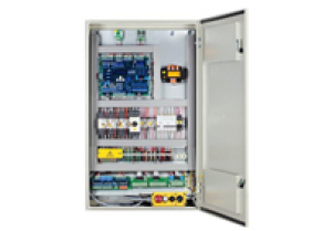
Контроллер для системы управления лифтом ARL 300
Назад в каталог
Контроллер для системы управления лифтом ARL 300

Артикул: ARL 300
Под заказ
Задать вопрос продавцу
- Описание товара
- Характеристики
- Отзывы0
| Подходит для всех видов систем управления в гидравлических и канатных лифтах до 24 остановок |
| Групповая работа до 4 групп |
| Открывание с открытыми дверями и открывание дверей с помощью внутренних реле для мостов |
| Схема защиты двигателя внутренней последовательности |
| Встроенные входы и выходы управления дверью |
| Программируемое 7-сегментное меню для индикаторов, Серый, инвертированный Серый, Двоичный, инвертированный Выходы двоичного кода и сигналы выхода на выход |
| Отдельные буквенно-цифровые названия этажей для каждой остановки |
| Сохранение последних 60 ошибок в памяти позволяет отслеживать обратное отслеживание ошибок |
| Цифровые и сигнальные выходы с защитой от короткого замыкания |
| FX_SERI до 16 остановок, экономия на кабельных и трудовых расходах с использованием карт последовательного интерфейса FX_SERI_32 на 16 остановок |
| Зарядка в гидравлических лифтах Аварийная загрузка с 2 батареями 12 В, производимыми карточкой ARL-SARJ |
| Функция аварийного автовосстановления для безредукторных лифтов |
| Соединительные платы, которые упрощают соединения с помощью плоских кабелей, экономят терминалы платы |
ПОЛЬЗОВАТЕЛЬСКИЙ ИНТЕРФЕЙС
| Регулируемые параметры системы с помощью ЖК-дисплея и кнопок на карте пользователем |
| Экран, показывающий состояние лифта в нормальной работе, с кодом ошибки в случае ошибки |
| Регулировка контрастности (яркости) экрана Lcd с помощью клавиш на карте |
| Меню PUK-кода защиты от защиты паролем и несанкционированного использования |
| Турецкий, английский, русский, голландский, румынский, немецкий, итальянский варианты меню |
ОБЩИЕ СВОЙСТВА
| Количество остановок | : | 24 остановки |
| Тип управления | : | Любая система трафика |
| Тип привода | : | Быстрый пар гидравлических бесступенчатая скорость Редукторной тяговой машина Gearless машина (машина жилая и МД) |
| Командир группы | : | имеются |
| Последовательная связь | : | С кабиной |
| Дополнительные функции | : | Внутренняя схема моста для двери Встроенная автоматическая регулировка двери Внутренняя фазовая последовательная защита двигателя Программируемый выход серого / двоичного кода для индикации |
Вам может понравиться
Быстрый просмотр
Под заказ
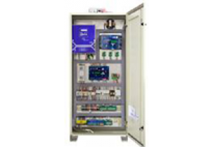
ARL-300
Станция управления лифтом
Быстрый просмотр
Под заказ
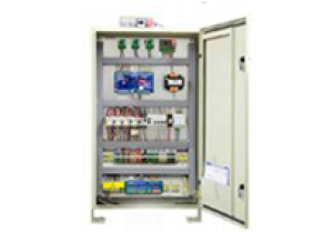
ARL-200
Станция управления лифтом
Быстрый просмотр
Под заказ
ARL 100
Станция управления лифта
Быстрый просмотр
в наличии
Плата управления для телескопических подъемных дверей с двигателем 24 В постоянного тока
-
Contents
-
Table of Contents
-
Bookmarks
Quick Links
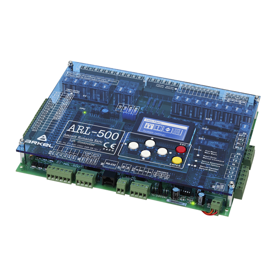
ARL-500
LIFT CONTROL SYSTEM
Programming Manual
Related Manuals for Arkel ARL-500
Summary of Contents for Arkel ARL-500
-
Page 1
ARL-500 LIFT CONTROL SYSTEM Programming Manual… -
Page 2
Keep the manual in a safe place and available to engineering and installation personnel during the control panel functioning period. ARKEL is not responsible for those mistakes that may be found in this manual and for the damages that they may cause. -
Page 3: Table Of Contents
5.3.3. REVKON PROGRAMMABLE INPUTS SCREENS …………… 18 5.3.4. KABKON PROGRAMMABLE INPUTS SCREENS …………… 19 5.4. OUTPUT STATUS SCREENS ……………………… 20 5.4.1. ARL-500 FIXED RELAY OUTPUTS SCREEN …………….20 5.4.2. ARL-500 PROGRAMMABLE RELAYS SCREENS …………….. 20 5.4.3. ARL-500 PROGRAMMABLE TRANSISTORS SCREENS …………21 5.4.4.
-
Page 4
7.1.4. JUMPERs on ARL-500 main controller ………………..92 7.1.4.1. Assigning the supply voltage of encoder in incremental positioning …………92 7.1.4.2. Activating the battery source of real time clock ………………..92 7.1.5. LCD CONTRAST trimpot on ARL-500 controller …………….92 7.2. REVKON C ……………………93 ONTROLLER 7.2.1. -
Page 5
7.4.5. KKBT Non-indicator Call Module ………………….. 121 7.4.5.1. KKBT Technical Data ……………………….122 7.4.5.2. KKBT Pin Assignments ………………………. 123 7.4.5.3 Floor Setting With Dipswitches On KKBT ………………124 8. ARL-500 DISPLAY MESSAGES ………………..125 8.1. STATUS MESSAGES ……………………….125 8.2. ERROR MESSAGES ……………………….132 ARL-500… -
Page 6: General
The ARL-500 Lift Controller complies with: Lift Directive 95/16/EC — European standards EN 81-1, EN 81-2 1.2. ELECTROMAGNETIC COMPATIBILITY (EMC) The ARL-500 Lift Controller and its components comply with the standards according to Directives of electro magnetic compatibility 2004/108/EC — EN 55011 Issue 2007…
-
Page 7: Manual Description
1.3. MANUAL DESCRIPTION Please read this manual carefully before installing the ARL-500 Lift Controller System. This manual will help you during installation of the ARL-500 controller and its components. In case of any problems, users are advised to contact manufacturer without any delay giving details of the problem.
-
Page 8: Introduction
ARL-500 is universal. With just a few parameter changes; it can be used for rope traction or hydraulic elevators, with two-speed or VVVF, up to 48 stops, and for groups of up to 8 elevators.
-
Page 9: Programming Interface
3. PROGRAMMING INTERFACE The user interface of ARL-500 lift controller system consists of 128×64 pixel resolution graphic LCD, keypads, LEDs, jumpers and trimpots. GRAPHIC LCD ARL-500 Controller has 128×64 pixel resolution illuminated blue graphic LC-Display. KEYPAD The ARL-500 controller is operated by using 6-key keypad. These keys have different functions in different displays.
-
Page 10: Keypad Functions According To Screen
4. KEYPAD FUNCTIONS ACCORDING TO SCREEN The ARL-500 controller is operated by using 6-key keypad. The functions of keys according to screen are described in the tables below: Key functions in the main screen To previous/next monitoring screens Open service options screen…
-
Page 11
Increase / decrease value Select menu item / set Exit submenu / menu item Key functions in the change password submenu Move cursor left / right Increase / decrease value Select menu item / change Exit submenu / menu item ARL-500 ARKEL 2010… -
Page 12
Exit submenu / menu item Key functions in the parking settings submenu Move cursor left / right To next / previous menu item Increase / decrease value Select menu item / set Exit submenu / menu item ARL-500 ARKEL 2010… -
Page 13: Display Screen
5. ARL-500 DISPLAY SCREEN The user interface of the ARL-500 controller is descripted below. The display of the ARL-500 controller is explained as required for installation and operating. ARL-500 Controller’s display screen consists of: Startup Screen Service Options Screen…
-
Page 14: Main Screen
5.2. MAIN SCREEN ARL-500 controller’s main screen summarizes the lift operation and the status of the lift system within separated windows. Messages, aliases, symbols and signs used in main menu are descripted below. Limit switches 818: Up limit switch…
-
Page 15
Door open signal Door Status It displays the status of the car door. Door is opening and door is open. Door is closing. Door is closed. Door is locked. Door is disabled in the “Debug tools” screen. ARL-500 ARKEL 2010… -
Page 16
Special JF counter: ML1 and 142 signals signals ML1-ML2 counter: ML1 and ML2 signals Encoder counter: It displays current position of the car relative to leveled position of lowest landing in cm. Sample value “2588cm” ● “ML1 ML2 •” ARL-500 ARKEL 2010… -
Page 17: Input Status Screens
5.3. INPUT STATUS SCREENS 5.3.1. ARL-500 FIXED INPUTS SCREEN In this screen some fixed inputs are monitored. The inputs which have ‘●’ (Closed) on the right hand side are active at the moment which have ‘.’ (Open) on the right hand side are inactive.
-
Page 18: Programmable Inputs Screens
(4 Screens, PI1to PI14 programmable inputs) In this screen all of the programmable inputs of ARL-500 controller are monitored. The inputs which have ‘●’ (Closed) on the left hand side are active at the moment which have ‘.’ (Open) on the left hand side are inactive.
-
Page 19: Kabkon Programmable Inputs Screens
2nd KABKON’s number is 2. All programmable inputs can be programmed by the user according to the needs of the system. Any input can be selected from the available inputs in the list of “KABKON inputs” menu. ARL-500 ARKEL 2010…
-
Page 20: Output Status Screens
‘.’ (Open) on the right hand side are not active. 7 relays of ARL-500 controler are constant in the system. You cannot redefine or change the following relay output terminals: RU1, RU2, 11, RH1, RH2, RP, RSD, RF of ARL-500 controller.
-
Page 21: Programmable Transistors Screens
5.4.3. ARL-500 PROGRAMMABLE TRANSISTORS SCREENS (2 Screens, PT1-PT6) In this screen all of the programmable transistors of ARL-500 controller are monitored.. The outputs which have ‘●’ (Closed) on the left hand side are active at the moment which have ‘.’ (Open) on the left hand side are inactive.
-
Page 22: Canbus Status Screens
(KK-x), car operating panels (KABKON), inspection box (REVKON) and the main controller (ARL-500) are monitored. ARL-500 Lift Control System communicates with car and landing units through serial data communication using two separated CANbus line. CAN1 for landing units and CAN2 for car units.
-
Page 23: The Status Of Landing Communication
‘A’ means connection of landing panel side A is made ‘B‘means connection of landing panel side B is made ‘-‘means no connection ‘AB‘means there is one LOP and serves to each entrance or there are 2 LOPS and 2 entrances. ARL-500 ARKEL 2010…
-
Page 24: Group Status Screen
Below the meaning of numbers and signs used in the screen is described. Member ID The own ID of ARL-500 Controller in elevator group. It ID shows of Controller inside the parenthesis (A), (B), (C), (D), (E), (F), (G) or (H) The accepted calls of the elavator.
-
Page 25: Error Status Screen
Controller can be blocked by the error after the maximum number of retries that is allowed. It is the only way to run lift again after it is blocked is controller reset. ARL-500 ARKEL 2010…
-
Page 26: V-T (Velocity-Time) Travel Curve Screen
The travel settings adjusted by the parameters of ARL-500 and the frequency inverter are monitored with a V-T (Velocity-Time) travel curve graph. By the help of the travel curve screen you can observe the travelling of elevator system.
-
Page 27: Car Command Entry Screen
Setting can be made by arrow keys within a range limited by a number of stops. Pressing ENTER will give a call order to the chosen landing or reset the given call. : selection of call entries : giving/cancelling a call : Returning to status screen ARL-500 ARKEL 2010…
-
Page 28: Manual Drive Screen
UP/DOWN buttons on the keypad. UP button gives up direction command and DOWN button gives down direction command. When the inspection mode is activated at car or re- call operation is activated at control cabinet this mode will be ineffective. ARL-500 ARKEL 2010…
-
Page 29: Service Options Screens
5.12. SERVICE OPTIONS SCREENS In this screen the service options of ARL-500 lift control system is monitored. The functions of service options are described below. Disable doors This function is used during installation, maintenance or servicing. When this function is activated, car calls are allowed but landing calls are not allowed.
-
Page 30
• If you hold down any of the buttons, you can see that button will start to blink faster. Thus, you can check if the call button is working properly or not. Random-10 ARL-500 will give 10 commands consecutively. Random-100 ARL-500 will give 100 commands consecutively. Random-500 ARL-500 will give 500 commands consecutively. -
Page 31: Menu Settings
All settings for lift controller are stored in main menu parameters. Menu parameters are classified into several groups to make it easy for users. 6.1. ENTERING MENU The ARL-500 is password protected to prevent unauthorised manipulation of control parameters and endangerment of persons or impairment of the lift system resulting from unauthorised access.
-
Page 32: Menu Tree
6.2. MENU TREE The ARL-500 main menu is displayed as a menu tree divided into submenus and menu items. System Settings Door Settings Call Responding Settings Display Settings Error Logs Programmable Inputs Programmable Outputs Hydraulic lift settings Shaft Learning…
-
Page 33
First time door close delay Wait on the floor Call responding settings Collection style Accept calls only in a single direction Avoid fake car calls checking lightbarrier Maximum car calls allowed at one time Cancelling car commands ARL-500 ARKEL 2010… -
Page 34
Inspection text Door open text Gray&Binary offset Show travel arrows Show collection arrows Error logs View error logs Delete error logs Programmable inputs ARL-500 inputs Input (PI-1) Input (PI-2) Input (PI-3) Input (PI-4) Input (PI-5) Input (PI-6) Input (PI-7) Input (PI-8) -
Page 35
Input (PI31-B1) Input (PI32-B1) Input (PI33-B1) Input (PI31-A2) KABKON-A2 inputs Input (PI32-A2) Input (PI33-A2) KABKON-B2 inputs Input (PI31-B2) Input (PI32-B2) Input (PI33-B2) KK-x inputs Programmable outputs ARL-500 transistors Transistor(PT1) Transistor(PT2) Transistor(PT3) Transistor(PT4) Transistor(PT5) Transistor(PT6) ARL-500 relays Relay(PR1) Relay(PR2) Relay(PR3) Relay(PR4) Relay(PR5) -
Page 36
Controller ID Bottom missing floors Top missing floors Parking settings Parking delay Parking time and parking floor settings Time and date settings System date and time Next maintenance date Motor protection settings R-S-T checking Motor temparature checking ARL-500 ARKEL 2010… -
Page 37
Daily UPS check Speed limit on rescue Program PLC Module Timer settings Timer number ON delay OFF delay Time unit Inputs PLC Input-1 PLC Input-2 PLC Input-3 PLC Input-4 Language Counters Stops on floors Reset counters Change password ARL-500 ARKEL 2010… -
Page 38
Emergency settings Primary fire exit Secondary fire exit Panic exit floor Headroom protection system Headroom/Pit protection Cartop protection lightbarrier Return to factory settings ARL-500 ARKEL 2010… -
Page 39: Menu Parameters
Car do not stop at limits until the bottom or top limit switches interrupts the elevator. Do not stop at limits! This function must only be used for testing the limit switches and must be used carefully! ARL-500 ARKEL 2010…
-
Page 40
►Inspection only When ARL-500 controller is switched on, it checks the bottom limit switch (817) to correct its position counter. If the inspection or recall control is activated before this correction drive, the system can only be operated in “Inspection only”. -
Page 41
Assign a programmable input to “25: (DRUN) Driver is during With feedback run” as a feedback signal input. The high signal (+24V) means driver is running and when the low signal (0V) is activated then the main contactors will be dropped. ARL-500 ARKEL 2010… -
Page 42: Door Settings
This section is designed for selection of active doors at each floor and the door time setting. 6.3.2.1. Door Type Settings ARL-500 system can control up to two semi-automatic or full-automatic doors which can be enabled or disabled for each floor independently. Door type settings and number of doors.
-
Page 43: Set Door Timings
This parameter is controlled by checking Manual door close close (terminal 130). When this timer overflows then an error waiting time is generated and the system goes to out of service. 10 – 300 seconds ►20 seconds ARL-500 ARKEL 2010…
-
Page 44
0 – 20 seconds ►2 seconds Enable approaching with car and landing doors open. The safety monitoring is integrated into the ARL-500 main board and enables car movements in the door zone with open car and landing doors. Door pre-opening Re-levelling function for hydraulic systems does not depend on this parameter. -
Page 45: Call Responding Settings
A reasonable number is the specified maximum number of passengers. one time 1 – 32 calls ►5 Allowing to cancel car command by pressing to the same buton for Cancelling car twice. commands Allowed This function is enabled Not allowed This function is disabled ARL-500 ARKEL 2010…
-
Page 46: Display Settings
A two-digit floor text can be set in a list of characters for each floor. This name is used by ARL-500 display and by all car/landing position indicators. List of characters using in ARL-500 for floor name texts Digits 0,1,…,9 Small letters a,b,…,z…
-
Page 47: Dot Matrix Settings
“Out of service Floor:#1” “Out of Service Error:#2” When the system is out of service and it is because of the error no: 2, the message in display will appear like: “Out of service Error:#1” ARL-500 ARKEL 2010…
-
Page 48
Inspection the Recall mode is activated from recall hand terminal or the Manual text drive is activated from ARL-500 keypad, this message is displayed at dot matrix indicators. This message can be changed by using the keypad and selecting the letters one by one. -
Page 49: Error Logs
These messages can be called up on the user interface of the ARL-500 or via HS500 hand terminal. Total errors: The number of total errors had occurred and stored in the memory.
-
Page 50: Programmable Inputs
6.3.6. Programmable Inputs ARL-500 controller is available with 14 programmable inputs whose functions can be selected by the user. Additionally, there are 6 programmable inputs on the REVKON board, 3 programmable inputs on each KABKON board and 1 programmable input on each KK-x board that can be assigned functions by the user.
-
Page 51: Revkon Inputs
6.3.6.2. REVKON inputs • In this menu, 6 rows of inputs (P21-PI26) are listed. REVKON inputs are shown on ARL-500 menu display as described below. “0: <undefined>” means no function is assigned to the input. Function number (Function alias) Function description…
-
Page 52: Kabkon Inputs
48. Door side setting can be ‘A’ or ‘B’. ‘B’ is used for the second entrance. KABKON programmable input code used in ARL-500 display is described below: Input Door side KABKON number…
-
Page 53: Kk-X Inputs
KK-x programmable input code shown in the upper row is described below: KK module — Landing number / Door side KK — KK-x programmable input function shown in the bottom row is described below: Function (Function alias) Function description number Undefined ARL-500 ARKEL 2010…
-
Page 54: List Of Input Functions
Active low (0V) Recall operation is activated when low (0V) signal is detected from the input terminal. In normal operating mode high (24V) signal must be applied to the terminal. Recall down Recall operation DOWN Active high (+24V) ARL-500 ARKEL 2010…
-
Page 55
— All calls from floors are cancelled. — System allows only the calls from inside the car and from ARL-500 controller. — If the car lands to any floor and if there is no any other call, the doors are opened and they stay open on that floor. -
Page 56
K19N-A Close limit (not)-A Same function with close limit switch Active high (+24V) (K19A) but this input is high activated. K16N-B Open limit (not)-B Same function with open limit switch Active high (+24V) (K16B) but this input is high activated. ARL-500 ARKEL 2010… -
Page 57
Door close sgn (inv)-B The inverted close limit switch signal of Active high (+24V) door side B for fireman service. If the limit switch signal turns on when the door comes to its limit, this function is used. ARL-500 ARKEL 2010… -
Page 58
When this signal is not used, the ARL-500 controller turns off the speed signals and the direction signals together. The high signal (+24V) means the driver is running and the low signal (0V) means the driver stops. -
Page 59
This function is used if the brake checkback signal is connected to ARL-500 mainboard and the brake checkbeck is control by ARL-500. If the control is made by the inverter this input is not used. Manual evac. mode This function is used with MRL systems… -
Page 60
External error This function is used to give an external trip to ARL-500 controller. ARL-500 controller gives an error when a high (+24V) signal is detected from the input terminal. This error makes the elevator goes to out of service. When the high signal turns off, controller returns to normal operation. -
Page 61
PLC Input 1 Active high PLI2 PLC In-2 PLC Input 2 Active high PLI3 PLC In-3 PLC Input 3 Active high PLI4 PLC In-4 PLC Input 4 Active high PLI5 PLC In-5 PLC Input 5 Active high ARL-500 ARKEL 2010… -
Page 62
PLC Input 12 Active high PLI13 PLC In-13 PLC Input 13 Active high PLI14 PLC In-14 PLC Input 14 Active high PLI15 PLC In-15 PLC Input 15 Active high PLI16 PLC In-16 PLC Input 16 Active high ARL-500 ARKEL 2010… -
Page 63: Programmable Outputs
“0: <undefined>” means no function is assigned to the output. Function number (Function alias) Function description Door-A close output (K3-A) The factory defaults of ARL-500 programmable transistors are listed in the table below: Output Function (Function Factory Function description…
-
Page 64: Relays
6.3.7.2. ARL-500 Relays • In this menu, 8 rows of outputs (PR1-PR8) are listed. Programmable outputs are shown on ARL-500 menu display as described below. “0: <undefined>” means no function is assigned to the output. Function number (Function alias) Function description…
-
Page 65: Revkon Relays
6.3.7.3. REVKON Relays • In this menu, 3 rows of outputs (PR21-PR23) are listed. REVKON relay outputs are shown on ARL-500 menu display as described below. “0: <undefined>” means no function is assigned to the output. Function number (Function alias)
-
Page 66: List Of Output Functions
ON when encoder is counting upwards Encoder down ON when encoder is counting downwards ED12 Encoder moving ON when encoder is counting up or down Binary code Floor number binary code bit- Binary code Floor number binary code bit- ARL-500 ARKEL 2010…
-
Page 67
Mains active Mains active output. ON when mains power is active. Mains power is controller by the inputs on ARL-500 controller (L1, L2, L3, N). UPT Test Supply of UPS phase input is For MRL connected over a UPS test systems. -
Page 68
The same function must be assigned to the programmable output. So that any programmable input of the elevator system can be bridged to any programmable output virtually by the ARL-500 controller. Bridge-2 A virtual output-2 Bridge-3 A virtual output-3 Bridge-4 A virtual output-4… -
Page 69
The car is on floor 5 Active high Level mod 8-6 The car is on floor 6 Active high Level mod 8-7 The car is on floor 7 Active high Level mod 8-8 The car is on floor 8 Active high ARL-500 ARKEL 2010… -
Page 70: Encoder Settings
Set this parameter “Slowing distance in low speed” same as the ADrive low speed parameter “1.9 Stopping distance”. For example if ADrive parameter “1.9 Deceleration distance” is set to 20cm, set this parameter to 20cm. 0 – 200 mm ►60 mm ARL-500 ARKEL 2010…
-
Page 71: Hardware Configuration
If this value is changed after a shaft-learning drive, a new shaft-learning run must be required. Because during the shaft-learning run, ARL-500 will determine the relation between pulse- count and centimeters by using this “flag length” information.
-
Page 72: Hydraulic Lift Settings
Time passed after the pawl is released until the pawl is locked. maximum delay 0,1 – 5 seconds ►5 seconds PAWL device delay Time passed after the car lands to a floor until the pawl device is released. before release 0,1 – 5 saniye ►1 seconds ARL-500 ARKEL 2010…
-
Page 73: Group Settings
6.3.10. Group Settings After connection of control panels in the elevator group only to do is setting each controller as A,B,C,…,H on ARL-500 menu. Each controller must have a different group The controller ID used by each controller in group operation. Controller Controller ID ID must be adjusted differently within each controller.
-
Page 74: Parking Settings
Because there is no active call and parking delay is exceeded the controller sends the car to a programmed parking floor. The ARL-500 controller has a scheduler that enables time dependent park drive programs. Each day can de divided in 5 time zones.
-
Page 75: Time And Date Settings
This section is used to adjust time and date setting and the make the maintenance configuration. 6.3.12.1. System date and time The date and the time of the ARL-500 controller. These settings must be checked during each service and adjusted if necessary. If the time is not set correctly, the time information of the error storage are useless.
-
Page 76: Motor Protection Settings
6.3.13. Motor Protection Settings This section is used to make the phase and motor protection settings. ARL-500 controller is available with integrated phase and motor protection circuits. Enables the phase loss and phase sequence checking. R-S-T checking ►Enabled When this parameter is set to “enable”, the terminals L1, L2, L3, Disabled and N on ARL-500 controller must be connected properly.
-
Page 77: Sound Settings
Hall button Enables the sound for landing call button when pressed. sounds ►On Car button Enables the sound for landing call buttons when pressed sounds ►On Enables the sound for car call buttons when pressed. Emergency alarm ►Off ARL-500 ARKEL 2010…
-
Page 78: Rescue Settings
In this submenu, the settings for evacuation operation (when mains power off) are adjusted. The evacuation type of elevator. Rescue method No rescue No rescue device. External (AKUS) ARKEL AKUS-SD evacuation unit is used (for only asynchrous drives). By releasing brake Evacuation operation with brake releasing method (for only synchrous drives). Zetadyn Evacuation operation by ZetaDYN inverter with UPS supply.
-
Page 79
The maximum evacuation time for the evacuation opeation if controlled by ARL-500 controller. Maximum time to When no floor level signal is detected in this period during rescue evacuation, controller interrupts the evacuation. This parameter must be set to a maximum time of floor to floor travel. -
Page 80: Language
6.3.16. Language This section is used to set the of graphic LCD and ARL-500 menu language The language of graphic LCD and ARL-500 menus. These languages are served in two packs. 5 languages are only Language available with each pack.
-
Page 81: Change Password
6.3.18. Change Password This section is used to set the password asked when entering the ARL-500 menu. User password has six digits. The default setting for the password is “000000” and you probably used this password to enter the menu. It is highly recommended to change it to an individual one before setting the lift parameters.
-
Page 82: Emergency Settings
“panic exit” floor. — After landing to designated floor, system opens the doors and cancels emitting the alarm. Lastly, system deactivates the “panic input” signal and starts to operate in normal mode. 1 – 48 ►1. Floor ARL-500 ARKEL 2010…
-
Page 83: Headroom/Pit Protection
The switches are connected to ARL-500 to detect if a switch is opened. The switch breaks when the corresponding landing door is opened. If a limit switch is broken and the car in not at that floor ARL-500 makes elevator operate only in inspection mode.
-
Page 84: Return To Factory Settings
6.3.21. Return to Factory Settings If you want to set all parameters to the values set just after production then you can use this section. It clears all the parameters entered by the user and set them to factory defaults. ARL-500 ARKEL 2010…
-
Page 85: Technical Data
7. TECHNICAL DATA 7.1. ARL-500 MAIN CONTROLLER 1 Drive relays (not programmable) 2 Programmable relays (can be programmed from ARL-500 menu) 3 Programmable outputs (can be programmed from ARL-500 menu) 4 Programmable inputs (can ben programmed from ARL-500 menu) 5 Door bridging safety circuit…
-
Page 86: Technical Data
7.1.1. ARL-500 Technical Data Description Value Dimensions 260 × 200 × 35 Length × width × height (mm) Working temperature ±0 — +60 °C Degree of protection IP20 Supply voltage 24 VDC ± 5 VDC Power consumption 400mA Control inputs…
-
Page 87: Terminals & Pin Assignment
7.1.2. ARL-500 TERMINALS & PIN ASSIGNMENT ARL-500 ►X1 : Drive Operation Terminals (Not programmable) Two Speed VVVF Hydraulic Down Direction Contactor Down Direction Contactor VC : Slow-Down Valve Up Direction Contactor Up Direction Contactor VA : Slow-Up Valve Contactors Supply Common…
-
Page 88
ARL-500 ►X5 : Motor Protection & Phase Failure Terminals Panel Thermostat & Motor Thermistor & T1- T2 Brake Resistor Thermostat (VVVF) & Oil Thermostat (Hydraulic) Neutral L1,L2,L3 Main Phase ARL-500 ►X6 : Signal Circuit Supply Terminals Signal Circuit Supply Input (+24VDC) -
Page 89: Leds On Arl-500 Main Controller
5V power supply of the processor is not working correctly. The hardware of the ARL-500 ontroller is faulty. Power on. Green Power off. 24V power supply of ARL-500 controller is not working correctly. Power on. Power off. Green 5V power supply of I/O peri-pherals is not working correctly.
-
Page 90
LEDs of programmable relays Color State Description Programmable relay 1 activated Programmable relay 2 activated Programmable relay 3 activated Programmable relay 4 activated Programmable relay 5 activated Programmable relay 6 activated Programmable relay 7 activated Programmable relay 8 activated ARL-500 ARKEL 2010… -
Page 91
Door bridging enable relay RBE activated Door zone magnetic switch SML1 closed Green Door zone magnetic switch SML2 closed Green LEDs of encoder inputs Color State Description Green Encoder signal phase A activated Green Encoder signal phase B activated ARL-500 ARKEL 2010… -
Page 92: Jumpers On Arl-500 Main Controller
7.1.4.1. Assigning the supply voltage of encoder in incremental positioning With incremental positioning, encoder supply voltages are assigned by using the encoder jumpers on ARL-500 controller. Two jumpers are used for each setting. 12V jumpers are delivered plugged at its rest position. It must be set according to the encoder supply voltage before operating ARL-500 controller.
-
Page 93: Revkon Car Top Controller
7.2. REVKON Car Top Controller 1 Programmable relays (can be programmed from ARL-500 menu) 2 Programmable inputs(can be programmed from ARL-500 menu) 3 Emergency light relay 4 Car fan relay 5 Car light relay 6 Programming socket 7 Battery fuse…
-
Page 94: Revkon Technical Data
REVKON A = 212mm G = 68mm B = 254mm H = 50mm C = 162mm I = 37mm D = 172mm J = 34mm E = 111mm K = 5mm F = 118mm L = 4mm ARL-500 ARKEL 2010…
-
Page 95: Revkon Terminals & Pin Assignment
REVKON ►XKON : KABKON Connector (10-pin) REVKON ►X-CB1 : Inspection Box CANbus Socket (4-pin) REVKON ►X-CB2 : Inspection Box CANbus Socket (4-pin) REVKON ►X21 : Alarm Horn Terminals HOP+ Alarm Horn + Terminal HOP- Alarm Horn – Terminal ARL-500 ARKEL 2010…
-
Page 96
Auxiliary Low Voltage Terminals YL2 (YK1) Intercom Button Inspection Alarm Button YL3 (AL) REVKON ►X27 : Car High Voltage Terminals Earth Car Supply Car Neutral YH5(3) Car shaft lighting phase Car shaft lighting contact YH4(3S) Auxiliary High Voltage Terminals ARL-500 ARKEL 2010… -
Page 97
The common supply voltage for signals ML1, ML2, 141 and 142. If 100 (+24Vdc) is present MLO puts out 24Vdc. If not MLO puts out 12Vdc from the battery voltage in inspection box. Supply Voltage (+24Vdc) 1000 Supply Voltage (0Vdc) ARL-500 ARKEL 2010… -
Page 98: Leds On Revkon Car Top Controller
Description PI21 Yellow Programmable Input 21 activated PI22 Yellow Programmable Input 22 activated PI23 Yellow Programmable Input 23 activated PI24 Yellow Programmable Input 24 activated PI25 Yellow Programmable Input 25 activated PI26 Yellow Programmable Input 26 activated ARL-500 ARKEL 2010…
-
Page 99
Description PR21 Programmable relay 1 activated PR22 Programmable relay 2 activated PR23 Programmable relay 3 activated LEDs of car relays Color State Description Car emergency light switched on RFAN Car fan switched on Car light switched on ARL-500 ARKEL 2010… -
Page 100: Kabkon Car Panel Module
16 X-CB1: Small size CANbus socket for car position indicator (LCD or Dot-matris display) connection 17 X-CB2: 2 pcs. big size CANbus socket for 2nd KABKON connection or HS500 hand terminal connection 18 XKON: REVKON connection socket ARL-500 ARKEL 2010…
-
Page 101: Kabkon Technical Data
Max. 500 mA load @ 12Vdc Emergency lighting output Approximately 2 hours duration with 1.3 Ah battery. Gong output 0,5W/8Ohm speaker KABKON Dimensional Drawing A = 88mm B = 96mm C = 139mm D = 147mm E = 4mm ARL-500 ARKEL 2010…
-
Page 102: Kabkon Terminals & Pin Assignment
Door Close Button & Indicator Supply Voltage (+24VDC) L-KAPA Indicator Output (0VDC) S-KAPA Button Input (High active) KABKON ► VAT : Car Priority Switch Socket (3-pin) Car Priority Switch & Indicator Supply Voltage (+24VDC) L-VAT Indicator Output (0VDC) S-VAT Button Input (High active) ARL-500 ARKEL 2010…
-
Page 103
Light Supply Ground 1000 Light Supply Ground KABKON ► HOP : Gong Output Socket (3-pin) Supply Voltage (+24VDC) Gong Output Supply Voltage (+24VDC) * : The top pin when the “KABKON” text written on board is read straight. ARL-500 ARKEL 2010… -
Page 104: Leds On Kabkon Car Command Cotrol Module
7.3.4. Trimpot on KABKON module Trimpot on KABKON module is used for adjusting volume of gongs in car operating panel. Gong volume is finely increased by turning trimpot anti-clockwise and is decreased by turning trimpot clockwise. ARL-500 ARKEL 2010…
-
Page 105: Dip-Switches On Kabkon Module
Number of commands selection The settings for number of car commands are described below: Set for car commands between 1 and 24 (KABKON board with this setting is showed as “KABKON1” on ARL-500 display) Set for car commands between 25 and 48 (KABKON board with this setting is showed as “KABKON2”…
-
Page 106: Call/Indicator Modules
1 CANbus connection sockets (big size) 2 CANbus connection socket (small size) 3 PC connection socket for programming 4 LCD contrast adjustment setting 5 4-key keypad 6 Buzzer for button sounds 7 PC programming socket 8 Memory chip ARL-500 ARKEL 2010…
-
Page 107: Lcd240X128A Technical Data
B = 136.2mm J = 15mm C = 102mm K = 23mm D = 117.6mm L = 68.1mm E = 125mm M = 144mm F = 110mm N = 159.1mm G = 51mm P = 4mm H = 64mm ARL-500 ARKEL 2010…
-
Page 108: Kklcd-A/Kklcd-B/Kklcd-C Call/Indicator Modules
1 Down direction led connection socket 2 Up direction led connection socket 3 Gong connection socket 4 Programmable input output connection socket 5 CANbus connection socket 6 2-key keypad 7 Gong volume setting. 8 PC programming socket 9 MCU programming socket ARL-500 ARKEL 2010…
-
Page 109: Kklcd-A/Kklcd-B/Kklcd-C Technical Data
B = 113mm C = 93mm D = 56.5mm E = 40mm F = 72mm G = 20.7mm H = 21.5mm J = 4mm KKLCD-A K = 13mm L = 19mm P = 7mm R = 3mm ARL-500 ARKEL 2010…
-
Page 110
A = 78mm B = 70mm C = 42mm D = 44mm E = 62mm F = 19.5mm G = 18mm H = 19mm J = 13mm KKLCD-C K = 7mm L = 3mm M = 4mm ARL-500 ARKEL 2010… -
Page 111: Kklcd-A/Kklcd-B/Kklcd-C Pin Assignments
X-CB1 Car CANbus Socket (4-pins) 100 * +24VDC Supply 1000 GND (Ground) CANL First CANbus terminal CANH Second CANbus terminal * : The leftmost pin behind KKLCD-X (socket writing must be on the top side of the card). ARL-500 ARKEL 2010…
-
Page 112
Doors A and B PARAMETER 3: BUTTON EXISTANCE SETTING When “Buton” is written in the indicator, with “+” button you can Buton choose if there is button connected to module or not. There is button There is no button ARL-500 ARKEL 2010… -
Page 113: Kk3X3057 Dot-Matrix Call/Indicator Modules
2 Up direction button connection socket 3 Speaker connection socket 4 Programmable input-output connection socket 5 CANbus connection socket (small size) 6 CANbus connection socket (big size) 7 2-key keypad 8 Gong volume setting 9 MCU programming socket ARL-500 ARKEL 2010…
-
Page 114: Kk3X3057 Technical Data
C = 109mm D = 114mm E = 45.7mm F = 38mm H = 22.8mm J = 17mm K = 15mm L = 18.5mm M = 7mm P = 7mm R = 4mm S = 3mm KK3X3057 ARL-500 ARKEL 2010…
-
Page 115: Kk3X3057 Pin Assignments
X-CB1 Car CANbus Socket (4-pins) 100 * +24VDC Supply 1000 GND (Ground) CANL First CANbus terminal CANH Second CANbus terminal * : The leftmost pin behind KK3X3057 (socket writing must be on the top side of the card). ARL-500 ARKEL 2010…
-
Page 116: Kk3X3057 Floor Adjustment
Door A and B PARAMETER 3: BUTTON EXISTANCE SETTING When “B” is written in the indicator, with “+” button you can choose if there is button connected to module or not. There is button There is no button ARL-500 ARKEL 2010…
-
Page 117: Kk2X3057 Dot-Matrix Call/Indicator Modules
7.4.4 KK2X3057 Dot-matrix Call/Indicator modules 1 Down direction button connection socket 2 Up direction button connection socket 3 Speaker connection socket 4 Programmable input-output connection socket 5 CANbus connection socket 6 2-key keypad 7 Gong volume setting 8 MCU programming socket ARL-500 ARKEL 2010…
-
Page 118: Kk2X3057 Technical Data
KK2X3057 Dimensional Drawing A = 49mm B = 73mm C = 58mm D = 64mm E = 45.7mm F = 38mm G = 14mm H = 13mm J = 12mm K = 4mm KK2X3057 L = 3mm ARL-500 ARKEL 2010…
-
Page 119: Kk2X3057 Pin Assignments
X-CB1 Car CANbus Socket (4-pins) 100 * +24VDC Supply 1000 GND (Ground) CANL First CANbus terminal CANH Second CANbus terminal * : The leftmost pin behind KK2X3057 (socket writing must be on the top side of the card). ARL-500 ARKEL 2010…
-
Page 120: Kk2X3057 Floor Adjustment
Door A and B PARAMETER 3: BUTTON EXISTANCE SETTING When “B” is written in the indicator, with “+” button you can choose if there is button connected to module or not. There is button There is no button ARL-500 ARKEL 2010…
-
Page 121: Kkbt Non-Indicator Call Module
1 Down direction button connection socket 2 Up direction button connection socket 3 Speaker connection socket 4 Programmable input-output connection socket 5 CANbus connection socket 6 Dipswitches for floor number setting 7 Gong volume setting 8 MCU programming socket ARL-500 ARKEL 2010…
-
Page 122: Kkbt Technical Data
15mA, 0.4W @ 24VDC Button-led (for each button) Gong 0.5W/8Ohm speaker Programmable output Max. 100mA, 2.5W @ 24VDC KKBT Dimensional Drawing A = 33mm B = 41mm C = 26mm D = 52mm E = 4mm F = 3mm KKBT ARL-500 ARKEL 2010…
-
Page 123: Kkbt Pin Assignments
X-CB1 Car CANbus Socket (4-pins) 100 * +24VDC Supply 1000 GND (Ground) CANL First CANbus terminal CANH Second CANbus terminal * : The rightmost pin behind KK2X3057 (socket writing must be on the top side of the card). ARL-500 ARKEL 2010…
-
Page 124: Floor Setting With Dipswitches On Kkbt
0 + 16 + 8 + 0 + 2 + 1 + 1 = 28 This landing call panel is indicated as “KK-28” on ARL-500 display. For door selection switches, use the table below: This panel commands both door-A and door-B…
-
Page 125: Display Messages
8. ARL-500 DISPLAY MESSAGES 8.1. STATUS MESSAGES The current status of elevator during the operations of controller is shown on ARL-500 display with the information on the top of display we called status message. The status messages are listed in the following table.
-
Page 126
(817) to sensors… correct its position counter. Earthquake evacuation mode is activated. The earthquake sensor input Earthquake (terminal DEP) on the ARL-500 evac. controller is active. Fire evacuation mode is activated. The fireman input (terminal YAN) Fire evacuation on the ARL-500 controller is active. -
Page 127
119. The stop circuit contacts between terminal 110 and 120 interrupted the safety circuit. All safety circuit inputs of ARL-500 controller are idle. — Emergency stop switch may be operated on the remote control Stop circuit off unit in normal mode (not Inspection or Recall). -
Page 128
“System settings > Limiters in inspection mode” either «Stop car immediately” or “Stop car at floor level” in the ARL-500 menu. The top limit switch (SKSR2) is activated Car is at the top floor and the top Inspection: 818 in inspection mode. -
Page 129
The manual control by keypad is active. LEFT + RIGHT keys on the ARL-500 keypad are pressed Inspection(*) together are lift goes into manual control mode from keypad. The bottom limit switch (SKSR1) is… -
Page 130
Cabin is ready for any command Ready (inside door-zone) command entry and inside entry. door zone. The system is ready for any command entry and outside Cabin is ready for any command Ready (outside door-zone) door zone. entry. Status Message Description Reason ARL-500 ARKEL 2010… -
Page 131
To operate in normal mode, at Safety circuit must be very first the system must learn shaft, safety circuits must be complete during shaft the shaft and to learn the shaft complete. learning! the safet circuit must be complete. ARL-500 ARKEL 2010… -
Page 132: Error Messages
8.2. ERROR MESSAGES The current error of the elevator system is shown in error status screen on ARL-500 display we called error message. ARL-500 controller saves these error messages listed in the following table. Error Message Description Reason — Check motor drive Max.
-
Page 133: Arkel
T1-T2 — Motor overheated. Monitoring Temperature monitoring of the drive via input of motor thermistor Motor on T1-T2 terminals of ARL-500 has terminals T1-T2. temperature too triggered. The voltage of terminal T1 is — The thermostat in the control high or PTC not 24VDC.
-
Page 134
Fire detected — Check the connection of terminal with 24V when a fire detected in YAN on ARL-500 system. The 24V supply of the ARL-500 board Power supply (100-1000) is below the permitted Check power supply and wiring voltage too low range of 24V — 20%. -
Page 135
ML1 and ML2 switches are activated simultaneously. simultaneously. Short-circuit? Check the “group settings” in the Group ID main menu and change the conflict. Change Group ID conflict in group operation. controller ID parameter if there are group ID. any conflicts. ARL-500 ARKEL 2010… -
Page 136
Inspection only! lightbarrier”. Check assigned PPSx input This error is triggered when A door connections on ARL-500. Pit protection assigned to one of the PPSx inputs was If this function is not used in your switch did not… -
Page 137
ARKEL Elektrik Elektronik Ticaret Ltd. Şti. Bostanci Yolu Cad. Şehit Sok. No:36 Yukari Dudullu Istanbul TURKIYE Tel: (+90 216) 540 03 10 — 11 -12 Fax: (+90 216) 540 03 09 E-mail : info@arkel.com.tr www.arkel.com.tr ARL-500 ARKEL 2010…
ARL-300
<< Другие контроллеры
.jpg)
Возможности системы:
- Интегрированный контроллер для электрических и гидравлических лифтов;
- Может работать с любым типом управления лифта;
- Допускает этажность до 24 этажей;
- Может объединять в группу до 4 лифтов;
- Интегрированная система безопасности для режима выравнивания и предоткрытия дверей;
- Интегрированная система контроля фаз;
- Интегрированная автоматическая система контроля дверей;
- Интегрированные выходы для информационных LCD и Dot Matrix дисплеев;
- Индикация состояния контактов цепи безопасности;
- Настройка и контроль параметров четырьмя многофункциональными кнопками с выводом информации на встроенный дисплей;
- Контроль и диагностика через меню с дружественным интерфейсом;
- Показания информационных дисплеев, установленных на этажах и в кабине, программируются с контроллера;
- Память на 60 ошибок;
- Защита цифровых входов от короткого замыкания с индикацией закороченного входа;
- Связь сигналов кабины по последовательному каналу (плата FX-SERI) уменьшает количество соединений;
- Подключение внешних сигналов осуществляется через удобные переходные платы;
- Аварийная плата ARL-SARJ осуществляет питание контроллера при внештатных ситуациях (гидравлические лифты);
- Соответствие правилам EN81-1/2;
- Меню контроллера на русском языке.