
Температурные контроллеры серии TC давно присутствуют в нашем ассортименте. Приборы применяются нами для собственного производства и широко реализуются торговым подразделением. По итогам анализа наиболее часто встречающихся вопросов возникающих в ходе эксплуатации была написана эта небольшая статья.
Не будем пока рассматривать аварийные ситуации. Разберем три, наиболее часто встречающиеся ошибки, которые пользователь может устранить самостоятельно.
Первая, самая простая и частая из возникающих проблем.
Контроллер переведен в режим «STOP»
Выглядит это вот так.
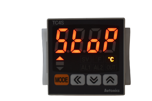
Ошибкой такая надпись не является. Появляется при одновременном нажатии кнопок «Вверх» и «Вниз». Надпись означает что регулирование остановлено. Продолжение регулирования включается повторным одновременным нажатием кнопок «Вверх» и «Вниз»
Вторая по числу обращений проблема.
На контроллере появляется надпись “OPEN”.
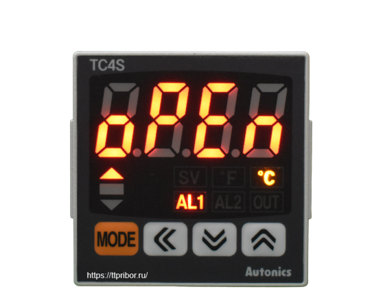
Появление надписи означает обрыв термопары. Очень частая проблема при эксплуатации термического оборудования. Термопары при неправильном выборе или использовании в некоторых видах техпроцессов выгорают достаточно быстро.
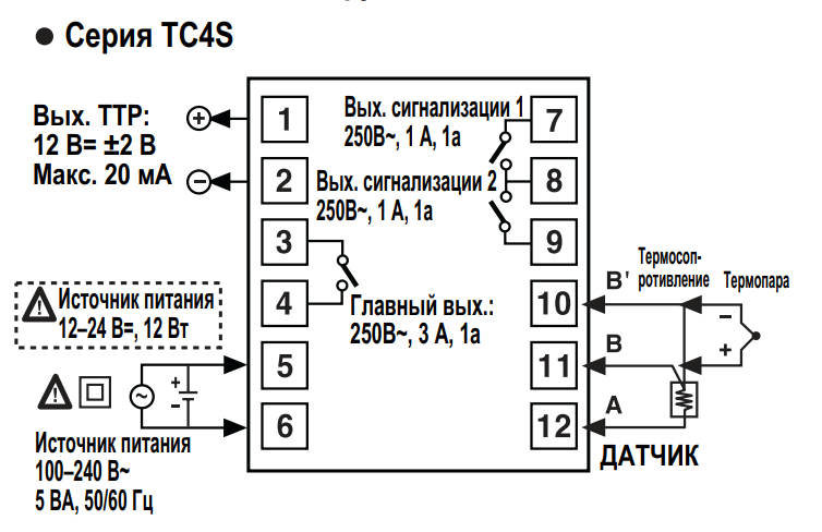
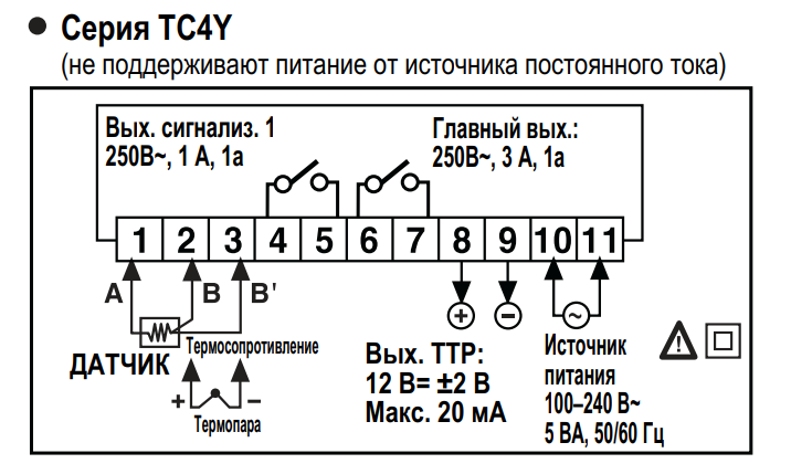
Наиболее быстрый способ диагностики – получаем доступ к колодке прибора, отключаем термопару и устанавливаем перемычку между входом 10 и 11 для серии TC4S и 2 и 3 для серии TC4Y.
Внимание! При манипуляциях – прибор должен быть отключен от сети. Соблюдайте правила техники безопасности.
Если перемычка установлена, прибор должен показывать температуру окружающей среды.
Третья ошибка. Встречается редко, но решение проблемы не описано ни в одной документации – производитель не смог догадаться что пользователь может так сделать.
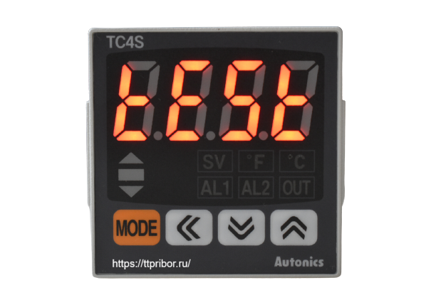
Появление
ошибки вызвано нажатием кнопок управления в момент включения (очень
часто) или наличие внутренней ошибки контроллера (крайне редко).
Контроллер перешел в тестовый режим.
Решение проблемы – сбросить ошибку.
Инструкция для выхода из тестового режима температурного контроллера TC4:
1. Сначала необходимо войти в тестовый режим. Для этого надо нажать стрелку «Вверх» одновременно с включением питания. Если вы видите на экране такую же надпись как выше – вы уже находитесь в тестовом режиме.
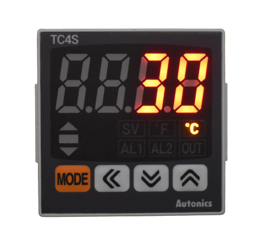
2. Если вы нажмете «Mode» два раза – начнется тест дисплея «1111»
3. При появлении надписи «1111», последовательно нажимайте кнопку «Вверх». На экране вы увидите значения: «22.22», «444.4», «88.8.8» до появления значения «Key»
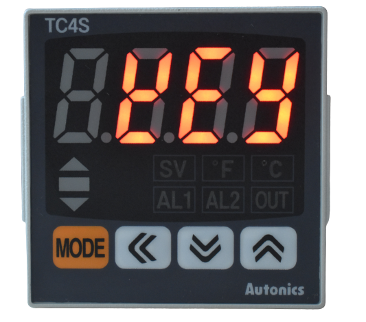
4. Когда дисплей устройства отобразит «Key», надо нажать стрелку «Вверх» и кнопку «Mode» одновременно.
5. Контроллер вышел из тестового режима.
Внимание! Все манипуляции необходимо проводить с подключенной термопарой!
Инструкции по эксплуатации на русском языке доступны в нашем файловом архиве.
Обращайтесь!
Появились вопросы? Пишите на почту support@ttpribor.ru
DRW170775AA
TEMPERATURE CONTROLLER
TC4 Series
I N S T R U C T I O N M A N U A L
Thank you for choosing our Autonics product.
Please read the following safety considerations before use.
Safety Considerations
※Please observe all safety considerations for safe and proper product operation to avoid hazards.
※Safety considerations are categorized as follows.
Warning Failure to follow these instructions may result in serious injury or death.
Caution Failure to follow these instructions may result in personal injury or product damage.
※The symbols used on the product and instruction manual represent the following
symbol represents caution due to special circumstances in which hazards may occur.
Warning
1. Fail-safe device must be installed when using the unit with machinery that may cause serious injury
or substantial economic loss. (e.g. nuclear power control, medical equipment, ships, vehicles,
railways, aircraft, combustion apparatus, safety equipment, crime/disaster prevention devices, etc.)
Failure to follow this instruction may result in fire, personal injury, or economic loss.
2. Install on a device panel to use.
Failure to follow this instruction may result in electric shock or fire.
3. Do not connect, repair, or inspect the unit while connected to a power source.
Failure to follow this instruction may result in electric shock or fire.
4. Check ‘Connections’ before wiring.
Failure to follow this instruction may result in fire.
5. Do not disassemble or modify the unit.
Failure to follow this instruction may result in electric shock or fire.
Caution
2
1. When connecting the power input and relay output, use AWG 20(0.50mm
) cable or over and tighten
the terminal screw with a tightening torque of 0.74~0.90N . m.
When connecting the sensor input and communication cable without dedicated cable, use AWG
28~16 cable and tighten the terminal screw with a tightening torque of 0.74~0.90N . m.
Failure to follow this instruction may result in fire or malfunction due to contact failure.
2. Use the unit within the rated specifications.
Failure to follow this instruction may result in fire or product damage.
3. Use dry cloth to clean the unit, and do not use water or organic solvent.
Failure to follow this instruction may result in electric shock or fire.
4. Do not use the unit in the place where flammable/explosive/corrosive gas, humidity, direct sunlight,
radiant heat, vibration, impact, or salinity may be present.
Failure to follow this instruction may result in fire or explosion.
5. Keep metal chip, dust, and wire residue from flowing into the unit.
Failure to follow this instruction may result in fire or product damage.
Ordering Information
T C 4 S
1 4 R
N
Indicator — Without control output
Control output
R
Relay output+SSR drive output
2
24VAC 50/60Hz, 24-48VDC
Power supply
4
100-240VAC 50/60Hz
N
No alarm output
Sub output
1
Alarm1 output
2
Alarm1 + Alarm2 output
※2
S
DIN W48
H48mm (terminal block type)
SP
DIN W48
H48mm (11pin plug type)
Y
DIN W72
H36mm
Size
M
DIN W72
H72mm
H
DIN W48
H96mm
W
DIN W96
H48mm
L
DIN W96
H96mm
Digit
4
9999 (4 Digit)
Setting type
C
Set by touch switch
Item
T
Temperature controller
※1: In case of the AC voltage model, SSR drive output method (standard ON/OFF control, cycle control,
phase control) is available to select.
※2: It is unavailable for TC4SP, TC4Y.
※3: Sockets for TC4SP (PG-11, PS-11(N)) are sold separately.
※ The above specifications are subject to change and some models may be discontinued
without notice.
※ Be sure to follow cautions written in the instruction manual and the technical descriptions
(catalog, homepage).
Specifications
TC4 Series
Series
TC4S
TC4SP
TC4Y
TC4M
Power
AC power
100-240VACᜠ 50/60Hz
supply
AC/DC Power 24VACᜠ 50/60Hz, 24-48VDCᜡ
Allowable voltage range 90 to 110% of rated voltage
Power
AC power
Max. 5VA (100-240VAC 50/60Hz)
consumption
AC/DC Power Max. 5VA (24VAC 50/60Hz), Max. 3W (24-48VDC)
Display method
7Segment (Red), Other display (Green, Yellow, Red LED)
Character size (W×H)
7.0×15.0mm
7.4×15.0mm 9.5×20.0mm 9.5×20.0mm 7.0×14.6mm 11.0×22.0mm
Input
RTD
DPt100Ω, Cu50Ω (Allowable line resistance max.5Ω per a wire)
type
TC
K (CA), J (IC), L (IC)
At room temperature (23℃±5℃): (PV ±0.5% or ±1℃, select the higher one) ±1digit
RTD
Display
Out of room temperature range: (PV ±0.5% or ±2℃, select the higher one) ±1digit
accuracy
※1
※ For TC4SP, add ±1℃ by accuracy standard.
TC
Relay
250VACᜠ 3A 1a
Control
output
SSR
12VDCᜡ ± 2V 20mA Max.
Alarm output
AL1, AL2 Relay: 250VACᜠ 1A 1a (※TC4SP, TC4Y have AL1 only.)
Control method
ON/OFF and P, PI, PD, PID control
Hysteresis
1 to100℃/℉ (0.1 to 50.0℃/℉) variable
Proportional band (P)
0.1 to 999.9℃/℉
Integral time (I)
0 to 9999 sec.
Derivative time (D)
0 to 9999 sec.
Control period (T)
0.5 to 120.0 sec.
Manual reset
0.0 to 100.0%
Sampling period
100ms
Dielectric
AC power
2,000VAC 50/60Hz for 1min. (between input terminal and power terminal)
strength
AC/DC Power 1,000VAC 50/60Hz for 1min. (between input terminal and power terminal)
Vibration
0.75mm amplitude at frequency of 5 to 55Hz in each X, Y, Z direction for 2 hours
Mechanical
OUT: Min. 5,000,000 operations, AL1/2: Min. 5,000,000 operations
Relay
OUT: Min. 200,000 operations (250VAC 3A resistive load),
life cycle
Electrical
AL1/2: Min. 300,000 operations (250VAC 1A resistive load)
Insulation resistance
Min. 100MΩ (at 500VDC megger)
Noise immunity
Square-wave noise by noise simulator (pulse width 1㎲) ± 2KV R-phase and S-phase
Memory retention
Approx. 10 years (When using non-volatile semiconductor memory type)
Environ
Ambient temp. -10 to 50℃, Storage: -20 to 60℃
-ment
Ambient humi. 35 to 85%RH, Storage: 35 to 85%RH
Double insulation or reinforced insulation (mark:
Insulation type
measuring input part and the power part: AC power 2kV, AC/DC Power 1kV)
Approval
Approx. 141g
Approx. 123g
Approx. 174g
Approx. 204g
※2
Weight
(approx. 94g)
(approx. 76g)
(approx. 85g)
(approx. 133g)
※1: Thermocouple L (IC) type, RTD Cu50Ω
At room temperature (23℃ ±5℃): (PV ±0.5% or ±2℃, select the higher one) ±1digit
Out of room temperature range: (PV ±0.5% or ±3℃, select the higher one) ±1digit
In case of TC4SP Series, ±1℃ will be added.
※2: The weight includes packaging. The weight in parentheses is for unit only.
※Environment resistance is rated at no freezing or condensation.
Unit Description
1
1
2
3
4
2
5
8
6
7
3
5
1. Present temperature (PV) display
5. Control/alarm output indicator
RUN mode: Present temperature (PV) display.
OUT: It will turn ON when control output (Main Control
Parameter setting mode: Parameter or
Output) is ON.
parameter setting valuedisplay.
※ In case of CYCLE/PHASE control of SSR drive
output, it will turn ON when MV is over 3.0%.
2. Deviation indicator, Auto-tuning indicator
(only for AC power type)
It shows current temperature (PV) deviation
AL1/AL2: It will light up when alarm output Alarm1/
based on set temperature (SV) by LED.
Alarm2 are on.
No. PV deviation temp. Deviation display
6.
key
1
Over 2℃
indicator ON
Used when entering into parameter group, returning
2
Below ±2℃
indicator ON
to RUN mode, moving parameter, and saving setting
3
Under -2℃
indicator ON
values.
The deviation indicators (
,
,
) flash by
7. Adjustment
every 1 sec. when operating auto tuning.
Used when entering into set value change mode, digit
moving and digit up/down.
3. Set temperature (SV) indicator
Press any front key once to check or change
8. FUNCTION key
current set temperature (SV), the set
Press
+
※1
temperature (SV) indicator is ON and preset set
STOP, alarm output cancel, auto-tunning) set in inner
value is flashed.
parameter [DI-K].
※ Press
+
4. Temperature unit (℃/℉) indicator
It shows current temperature unit.
operation to move digit.
Input Sensor and Temperature Range [IN-T]
Input sensor
Display
Temperature range (℃) Temperature range (℉)
K (CA)
-50 to 1200
KCA
Thermocouple
J (IC)
-30 to 500
JIC
※3
L (IC)
LIC
-40 to 800
DPtH
-100 to 400
DPt100Ω
-100.0 to 400.0
DPtL
RTD
-50 to 200
CUsH
Cu50Ω
-50.0 to 200.0
CUsL
Installation
TC4S/SP (48
48mm) Series
TC4Y (72
36mm) Series
※ Mount the product on the panel, fasten bracket by pushing with tools as shown above.
(In case of TC4Y, fasten bolts for bracket.)
Dimensions
TC4S Series
TC4W
TC4H
TC4L
48
6
64.5
TC4Y Series
72
7
TC4M Series
72
6
64.5
Bracket
TC4S/TC4SP Series
31
48.6
20
5
45
, Dielectric strength between the
Approx. 194g
Approx. 194g
Approx. 254g
(approx. 122g)
(approx. 122g)
(approx. 155g)
15
21
55
56
6
7, 8
4
Connections
※ TC4 Series has selectable control output; Relay output, and SSR drive output.
AC/DC power type does not have SSRP function.
TC4S Series
SSR OUT:
1
7
AL1 OUT:
12VDC ±2V
250VAC 1A 1a
20mA Max
2
8
AL2 OUT:
250VAC 1A 1a
3
9
Relay OUT:
B’
RTD
250VAC 3A 1a
4
10
B
5
11
—
+
A
※1
6
12
SOURCE
SENSOR
100-240VAC 5VA 50/60Hz
24VAC 5VA 50/60Hz
24-48VDC 3W
TC4Y Series
Relay OUT:
keys for 3 sec. to operate function (RUN/
AL1 OUT:
250VAC 3A 1a
250VAC 1A 1a
1 2 3 4 5 6 7 8 9 10 11
keys at the same time in set value
A
B
B’
— +
SSR OUT:
RTD
SENSOR
12VDC ±2V
※1
SOURCE
20mA Max
100-240VAC 5VA 50/60Hz
TC
24VAC 5VA 50/60Hz
24-48VDC 3W
-58 to 2192
TC4M Series
-22 to 932
1
10
-40 to 1472
-148 to 752
2
11
-148.0 to 752.0
3
12
-58 to 392
-58.0 to 392.0
4
13
SSR OUT:
AL1 OUT:
12VDC ±2V
250VAC 1A 1a
20mA Max
5
14
AL2 OUT:
250VAC 1A 1a
6
15
Other Series
Relay OUT:
250VAC 3A 1a
B’
RTD
7
16
8
17
B
A
9
18
SOURCE
SENSOR
100-240VAC 5VA 50/60Hz
24VAC 5VA 50/60Hz
24-48VDC 3W
※Use crimp terminals or teminals of size specified below.
a b
<Round>
<Forked>
a
Min. 3.0mm
Min. 3.0mm
b
Max.5.8mm
Max.5.8mm
TC4SP Series
6
72.2
48
58.5
45
84
77
TC4H Series
48
6
64.5
Panel cut-out
TC4Y Series
30
A
60
C
TC4M, TC4W, TC4H, TC4L Series
Size
A
B
C
Model
TC4S
Min. 65
Min. 65
45
+0.6
0
TC4SP
Min. 65
Min. 65
45
+0.6
46
0
TC4Y
Min. 91
Min. 40
68
+0.7
0
TC4M
Min. 90
Min. 90
68
+0.7
0
TC4H
Min. 65
Min. 115
45
+0.6
0
TC4W
Min. 115
Min. 65
92
+0.8
0
12
TC4L
Min. 115
Min. 115
92
+0.8
0
23.9
SSR Drive Output Selection Function (SSRP Function)[SSrM]
● SSRP function is selectable one of standard ON/OFF control, cycle control, phase control by utilizing
standard SSR drive output.
TC4SP Series
● Realizing high accuracy and cost effective temperature control as linear output(cycle control and
phase control).
6
—
5
7
AL1 OUT:
● Select one of standard ON/OFF control [STND], cycle control [CYCL] , phase control [PHAS] at [SSrM]
Relay OUT
250VAC 1A 1a
parameter of Parameter group 2. For cycle control, connect zero cross turn-on SSR or random
250VAC 3A 1a
+
4
8
turn-on SSR. For phase control, connect random turn-on SSR.
SSR OUT:
12VDC ±2V
TC
RTD
B’
3
9
TC
20mA Max
—
—
Temperature controller
+
B
2
10
+
—
A
+
1
11
※1
SENSOR
SOURCE
100-240VAC 5VA 50/60Hz
24VAC 5VA 50/60Hz
24-48VDC 3W
TC4H, TC4W, TC4L Series
1
13
Power
100-240VAC
2
14
50/60Hz
3
15
※ When selecting cycle or phase control mode, the power supply for a load and a temperature
4
16
controller must be the same.
5
17
※ In case of selecting cycle [CYCL] or phase [PHAS] control mode for PID control, control cycle [T] is
not allowed to set.
6
18
※ For AC/DC power model (TC4 — 2R), this parameter [SSrM] is not displayed and it is available only
7
19
standard control by relay or SSR.
SSR OUT:
AL1 OUT:
12VDC ±2V
250VAC 1A 1a
20mA Max
8
20
1)Standard ON/OFF control [STND]
AL2 OUT:
250VAC 1A 1a
A mode to control the load in the
9
21
same way as Relay output type.
Relay OUT:
250VAC 3A 1a
B’
RTD
TC
10
22
(ON: output level 100%,
—
OFF: output level 0%)
+
B
11
23
—
+
A
2)Cycle control [CYCL]
12
24
※1
SENSOR
SOURCE
A mode to control the load by
100-240VAC 5VA 50/60Hz
24VAC 5VA 50/60Hz
repeating output ON / OFF
24-48VDC 3W
according to the rate of output
TC
※1: AC power: 100-240VAC 5VA 50/60Hz
—
within setting cycle.
AC/DC power: 24VAC 5VA 50/60Hz
+
Having improved ON / OFF noise
24-48VDC 3W
feature by Zero Cross type.
3)Phase control [PHAS]
A mode to control the load by
a
controlling the phase within
AC half cycle. Serial control is
a b
c
b
available.
<Crimp terminal>
(unit: mm)
Random turn-on SSR must be
Terminal number
a
b
c
used for this mode.
1 to N
6
Max. 1.9
Max. 4.0
(unit: mm)
TC4W Series
96
6
64.5
TC4L Series
96
6
64.5
Terminal cover (sold separately)
RSA-COVER (48×48mm)
RMA-COVER (72×72mm)
70
3
48.4
9.8
22.5
D
RHA-COVER
RLA-COVER (96×96mm )
(48×96mm, 96×48mm )
45
47.2
4
94
3
+0.6
0
45
+0.6
0
31.5
+0.5
0
68
+0.7
0
92
+0.8
0
45
+0.6
0
92
+0.8
0
SSR voltage output
SSR module
(TC4Series)
(12VDC)
Load
AC
OUT
ON
OFF
ON
OFF
AC
OUT
50Cycle
50Cycle
50%
80%
AC
OUT
10%
50%
TC Series
Output connections
See H-139 page for output.
Application of relay output type
A
TC Series
Condenser
0.1㎌
630V
Relay contact terminal
Keep A length as long as possible when wiring the
temperature controller and the load. If wire length of A is
short, counter electromotive force which occurs from a coil
of magnet switch & power relay may flow in power line of
the unit, and it may cause malfunction.
If wire length of A is short, please connect mylar
condensers 104(630V) on the both ends of «
coil) to protect electromotive force.
Simple «error» diagnosis
● When the load (Heater etc) is not operated
Please check operation of the OUT lamp located in front
panel of the unit.
If the OUT lamp does not operate, please check the
parameter of all programmed mode.
If lamp is operating, please check the output(Relay, SSR
drive voltage) after separating output line from the unit.
● When it displays OPEN during operation
This is a warning that external sensor is open.
Please turn off the power and check the wire state of the
sensor. If sensor is not open disconnect sensor line from
the unit and short the input +, — terminal. Turn on the
power of the unit and check the controller displays room
temperature.
If this unit cannot display room temperature, this unit is
broken. Please remove this unit and contact our service
center. (When the input mode is thermocouple, it is
available to display room temperature.)
H-66
Heater
Power
Magnet or
Relay contact
» (magnet
Application of SSR drive output method
TC Series
+
Voltage
output
terminal
—
※ SSR should be selected by the capacity of load,
otherwise, it may short-circuit and result in a fire. Indirect
heated should be used with SSR for efficient working.
※ Please use a cooling plate or it may cause the capability
deterioration, breakdown of SSR for a long usage.
※ Refer to the H-63 page for phase/cycle control connections.
Caution for using
● The connection wire of this unit should be separated from
the power line and high voltage line in order to prevent
from inductive noise.
● For crimp terminal, select following shaped terminal (M3)
Max. 5.8mm
● Please install power switch or circuit-breaker in order to
cut power supply off.
● The switch or circuit-breaker should be installed near by
users.
● This unit is designed for temperature controlling only. Do
not apply this unit as a voltage meter or a current meter.
● In case of using RTD sensor, 3-wire type must be used.
If you need to extend the line, 3-wires must be used
with the same thickness as the line. It might cause
temperature difference if the resistance of line is different.
● In case of making power line and input signal line close,
line filter for noise protection should be installed at power
line and input signal line should be shielded.
● Keep away from the high frequency instruments.(High
frequency welding machine & sewing machine, big
capacitive SCR controller)
● When supplying measured input, if HHHH or LLLL is
displayed, measured input may have problem. Turn off
the power and check the line.
● Installation environment
It shall be used indoor.
Altitude Max. 2000m.
Pollution Degree 2
Installation Category Ⅱ .
SSR
I
L
Power
N
O
P
A
U
D
Load power
T
Max. 5.8mm