
- Manuals
- Brands
- BlueBox Manuals
- Air Conditioner
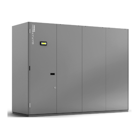
- Datatech
- Installation, use and maintenance manual
-
Contents
-
Table of Contents
-
Bookmarks
Quick Links
Datatech
EN
Installation, use and maintenance manual
07-10-2016
Summary of Contents for BlueBox Datatech
- Page 1
Datatech Installation, use and maintenance manual 07-10-2016… - Page 2
THANK YOU Thank you for choosing our product. It is the result of many years’ experience and careful design and has been built with first-class quality materials and advan- ced technologies. The CE marking also guarantees that the equipment meets the requirements of the European Machinery Safety Directive. The quality level is constantly monitored, and therefore our products are synonymous with Safety, Quality and Reliability. -
Page 3: Table Of Contents
Contents Introduction Conformity Description 1.2.1 Symbols 1.2.2 Labels Safety General safety precautions 2.1.1 Discharge of the safety valves Basic rules 2.2.1 Water flow rate at the heat exchangers 2.2.2 Water composition Noise Residual risks Safety information on the refrigerant fluid 2.5.1 Hazards and health consequences Receiving the product and storage Reception Transport Handling…
- Page 4
4.8.1 Switching the unit on/off 4.8.2 Change of set points Wiring diagram Installation Dimensions and weight Place of installation Installation 5.3.1 Positioning the units 5.3.2 The base frame (Versions UNDER) 5.3.3 Separate fan section 5.3.4 Positioning the air condenser 5.3.5 Minimum distances Hydraulic connections 5.4.1 Connections to the plate condenser 5.4.2 Connections to the water chiller coils 5.4.3 Connection to the condensate drain 5.4.4 Connection to the hot water coil 5.4.5 Connection to the humidifier Electrical connections Refrigeration connections 5.6.1 Piping implementation 5.6.2… - Page 5
Decommissioning We reserve the right to make changes without any prior notice. Translation from original instructions… -
Page 6: Introduction
INTRODUCTION 1.1 Conformity With regard to relevant regulations and directives, see the declaration of conformity that is an integral part of the manual. 1.2 Description 1.2.1 Symbols A description of the main symbols used in this manual and on the labels affixed to the unit is given below. Danger symbol;…
-
Page 7: Labels
1.2.2 Labels For the constructional features, available models and technical data, please refer to the Technical Booklet. The model, serial number, features, power supply voltage and so on are shown on the labels affixed to the unit (the following illustrations are shown only as an example). The Manufacturer adopts a continuous development policy and, in this perspective, reserves the right to make changes and improvements to the documentation and to the units without prior notice.
-
Page 8: Safety
SAFETY 2.1 General safety precautions The equipment operator is responsible for complying with regulatory obligations. The equipment operator is the person who has actual control over the technical operation and free access, which means the possibility of monitoring its components and their operation and the possibility of granting access to third parties. The equipment operator has the power (including financial power) to decide on technical modifications, checks and repairs.
-
Page 9: Discharge Of The Safety Valves
In units with capacitors and/or inverters, certain components can remain live for several minutes even after having turned off the main switch. Wait 10 minutes before working on the electrical parts of the unit. Circuits supplied from external sources (made with orange cable) can remain live even after the power sup- ply to the unit has been turned off.
-
Page 10: Basic Rules
2.2 Basic rules All the units are designed and built in compliance with Directive 2014/68/EU of the European Parliament and of the Council of 15 May 2014 on the approximation of the laws of the Member States relating to pressure equipment. To ensure maximum safety, in order to prevent possible risks, follow the instructions below: — this product contains pressurised vessels, live components, moving mechanical parts and very hot and cold surfaces that, in certain situations, can pose a risk: all maintenance work must be carried out by skilled personnel equipped with…
-
Page 11: Water Flow Rate At The Heat Exchangers
2.2.1 Water flow rate at the heat exchangers It is necessary to ensure that the water flow rate during operation is the nominal flow rate of the unit stated in the Technical Booklet. In any case, refer to the specific Technical Booklet for the allowed conditions for water flow in and out of the exchangers.
-
Page 12: Noise
2.3 Noise The starting of the unit, with activation of its components, emits a noise whose intensity varies depending on the operating level. The correct location choice and the correct installation prevent the unit causing annoying noise due to resonances, reflections and vibrations.
-
Page 13: Safety Information On The Refrigerant Fluid
2.5 Safety information on the refrigerant fluid This chapter only applies to units equipped with a cooling circuit; It does not apply to those where there are only one or two water coils. This product contains fluorinated greenhouse gases included in the Kyoto protocol. Do not release these gases into the atmosphere.
-
Page 14: Receiving The Product And Storage
RECEIVING THE PRODUCT AND STORAGE 3.1 Reception On receiving the unit, check that it is undamaged, bearing in mind that it left the factory in perfect condition. Report any signs of damage immediately to the transporter and make a note of these on the Delivery Sheet before signing The relevant sales department or the manufacturer should be informed of the extent of the damage as soon as possible.
-
Page 15: Handling
3.3 Handling Before each unit handling operation, check that the lifting capacity of the machinery used is compatible with the weight of the unit. Handling must be carried out by adequately equipped qualified personnel. In all lifting operations, make sure the unit is firmly secured in order to prevent accidental falls or overturning. Lifting must be carried out by qualified and authorised personnel taking the necessary precautions;…
- Page 16
Pallet trucks or forklift trucks with short forks can be used (e.g. piano lifts) for handling inside buildings. The unit should be lifted as little as possible when handling in order to avoid overturning risks. If forklift trucks with short forks are used, position some protective material between the unit and the forklift trucks and the clamping belts. -
Page 17: Units With Separate Ventilation Section
3.3.2 Units with separate ventilation section The same means used for the unit can be employed to handle the fan section. 3.4 Storage The units are built to be installed in indoor environments. Storage outdoors is not allowed. Upon receipt they must be put in locations protected from weather agents. Since the remote condensing unit is designed to be installed outdoors, it can withstand outdoor atmospheric conditions.
-
Page 18: Product Description
PRODUCT DESCRIPTION 4.1 Intended use The units are designed to control the air temperature and humidity, in «close control» applications and in technological ones in general. Their use is recommended within the operating limits indicated in the Technical Booklet. 4.2 Unintended use The unit must not be used: — in an explosive atmosphere;…
-
Page 19: Control And Safety Devices
4.3 Control and safety devices The unit is integrally managed by an electronic microprocessor control that, through the various temperature and pressure sensors installed in the unit, keeps its operation within the safety limits. All the parameters involved with control of the unit are shown in the “Control Manual” that is an integral part of the docu- mentation of the unit.
-
Page 20: Air System
4.7 Air system 4.7.1 Unit fans The units of the series are equipped with radial fans with reverse blades, with external rotor motor directly coupled to the impeller. These fans do not need any special maintenance as they do not have any couplings (belts, pulleys). The fans can be integrated in the unit or supplied in a separate section.
-
Page 21: Air Flow Sensor
Size «K» for units with integrated fans «K» for units with fans on separate section 4.7.3 Air flow sensor This device prevents the unit operating in the absence of air flow. The control is effected by a differential pressure switch which measures the pressure difference upstream and downstream of the evaporator coil and the air filter, or by a differen- tial pressure transducer in units where EC fans with control of the air flow are present.
-
Page 22: Air Filters
4.7.6 Air filters The units are equipped with air filters on the recirculation line with varying degrees of efficiency. The filter change must always take place from the front of the unit. The filters of the direct expansion units have the same overall size of the evaporator coils, whether they are UNDER or OVER.
-
Page 23: Control Panel
4.8 Control panel The unit is integrally managed by an electronic system with microprocessor, having a graphic display as interface. By using the display, you can access all the unit’s functions, such as visualising the operating parameters, setting the para- meters, managing and analysing any problems.
-
Page 24: Wiring Diagram
4.9 Wiring diagram The wiring diagram is an essential part of the documentation and is present inside each unit. It is essential to refer to this document if you are unsure about anything or need further explanations regarding the auxiliary electrical connections and power connections as well as for the electrical specifications.
-
Page 25: Installation
INSTALLATION During installation or whenever work must be carried out on the unit, it is essential to strictly follow the instructions in this manual, comply with the directions on the unit and in any case take all necessary precautions. The pressures in the refrigerant circuit and the electrical components can create risky situations during installation and maintenance work.
-
Page 26: Installation
5.3 Installation Upon installation, these units require different stages of assembly, depending on their operation and type. The cases can be: — Units consisting of water coil only; the units are shipped from the factory already tested and only need electrical and hydraulic connections for installation.
-
Page 27: The Base Frame (Versions Under)
5.3.2 The base frame (Versions UNDER) The units with downward air flow require an adequate support system, as they are usually installed in rooms with a raised floor. For this purpose, the base frame with adjustable feet is available, if required can also be supplied with an air conveyor. Fig.
-
Page 28: Minimum Distances
5.3.5 Minimum distances These units require (as the minimum necessary) only a clear space in front of the unit, in order to allow opening the panels and the electric box and normal maintenance operations. In particular, refrigeration, plumbing and electrical connections must be accessed from the bottom of the unit.
-
Page 29: Hydraulic Connections
5.4 Hydraulic connections 5.4.1 Connections to the plate condenser Should the unit be equipped with integrated plate condensers, these must be connected to the heat dissipation system (cooling tower, dry cooler, ring). The dimensional drawings show the position of the water connections to the exchangers in their various configurations.
-
Page 30: Connections To The Water Chiller Coils
5.4.2 Connections to the water chiller coils The water chiller coil is fitted as standard with a two or three-way modulating valve, with an electric three-point or 0-10V servo-control (depending on the version or configuration). For the hydraulic connections (whether the coil is the main or the additional one) observe the following guidelines: — use copper or steel pipes;…
-
Page 31: Connection To The Hot Water Coil
5.4.4 Connection to the hot water coil Refer to the dimensional drawings for the position and size of the water connections. Please observe the following guidelines: — use copper or steel pipes; — adequately insulate the pipes; — install shut-off valves in/out of the unit; — install a thermometer and a pressure gauge at the input and output of the unit.
-
Page 32: Electrical Connections
5.5 Electrical connections All electrical operations must be carried out by personnel having the necessary legal requirements, and trained and infor- med on the risks connected with these operations. The sizing and characteristics of the power lines and relevant components must be determined by staff qualified to design electrical systems, following the international and national regulations of the place of installation of the units in conformity with the regulations in force at the time of installation.
-
Page 33: Refrigeration Connections
5.6 Refrigeration connections The units using the refrigeration cycle often require a remote installation of the capacitor. The cooling circuits equipped with shut-off valve, are charged in the factory with anhydrous nitrogen at a pressure of 12 bar. Warning: the following operations require pressurised pipes and brazed connections to be made, and these must be carried out by specialised staff in possession of the necessary qualifications in accordan- ce with current regulations.
- Page 34
Table 1A — R410A Recommended diameters — The thickness of the tube must be compatible with the refrigerant used and with current regulations Equivalent length Equivalent length Equivalent length Equivalent length Equivalent length Number 10 m 20 m 30 m 40 m 50 m Model of circuits Liquid Liquid Liquid Liquid Liquid 11.1 15.1 18.1 17.1 22.1 26.1 30.2 32.1 36.1 34.2 38.1 38.2… - Page 35
Table 1B — R410A Recommended diameters for units with inverter controlled compressors — The thickness of the tube must be compatible with the refrigerant used and with current regulations Equivalent length Equivalent length Equivalent length Equivalent length Equivalent length 10 m 20 m 30 m 40 m 50 m Model Circuit Liquid Liquid Liquid Liquid Liquid 12.1 16.1 23.1 27.1 33.1 35.2 36.2 45.2 44.2 58.2 66.3 82.3 100.4 Should the length of the cooling lines envisage an increase of the diameters compared with those required for… - Page 36
Table 2A — Refrigerant charge * for units with separate section circuits, excluding pipelines (compressors on / off) Refrigerant charge Refrigerant charge Refrigerant charge Refrigerant charge Refrigerant charge with condenser without condenser with condenser with condenser with condenser Model High-performance LN [kg] standard [kg] High-performance [kg] LN [kg] [kg] 11.1 15.1 18.1 17.1 22.1 26.1 30.2 32.1 36.1 34.2 38.1… - Page 37
Table 3 – Additional R410A refrigerant charges per metre of linear pipe Outer Diameter [mm] Gas [kg] Liquid [kg] 0.0045 0.0474 0.007 0.074 0.01 0.014 0.145 0.018 0.19 0.028 0.048 * Discharge saturation temperature 45 ° C, liquid temperature 40 ° C Suggested additional oil charge: over 20 metres of linear development of the pipes, add a quantity of oil equal to 2% in weight of the total refrigerant present in the circuit. -
Page 38: Changes In Temperature And Speed In The Cooling Lines
5.6.2 Changes in temperature and speed in the cooling lines Below are the diagrams for calculating the temperature variations in the delivery pipes and the liquid speed in the cooling line pipes. Fig. 11 Change of saturation temperature in the discharge lines This diagram is useful in order to approximately determine the variation in saturation temperature, per equivalent linear metre of pipe, on the basis of the cooling capacity and the diameter of the discharge line.
- Page 39
Fig. 13 Change of saturation temperature in the liquid lines This diagram is useful in order to determine the approximate variation in saturation temperature, per equivalent linear metre of pipe, on the basis of the cooling capacity and the diameter of the liquid line. Fig. -
Page 40: Change In Performance
5.6.3 Change in performance In order to calculate the actual pressure drop and the consequent performance reduction coefficient, use the graph «Change in the saturation temperature in the flow lines». Given the cooling capacity specifications for each refrigerant circuit: — find the pressure drop per metre of length according to the diameters actually used; — multiply them by the actual equivalent length for each diameter;…
-
Page 41: Vacuum And Refrigerant Charge
5.7 Vacuum and refrigerant charge Open the taps of the indoor unit and evacuate the pre-charged nitrogen before completing the refrigerant connections. Do not leave the refrigerant circuit open for more than 15-30 min as the high hygroscopic capacity of the oil may cause the absorption of moisture detrimental to the circuit.
-
Page 42: Commissioning
COMMISSIONING 6.1 Preliminary operations Make sure the main disconnect switch is in the OFF position. The unit should only be started up by qualified personnel authorised by the manufacturer. Check: — that the electrical connection has been made correctly and that all terminals are properly tightened. — that the voltage on the RST terminals is 400 V ±…
-
Page 43: First Starting
6.2 First starting In all the units pre-set for a remote condenser, make sure the correct electrical connection has been made and that the switch is in the «ON» position. In all units pre-set for a water connection, make sure there is water and that it can circulate properly. So that the unit can operate, the external OK signal device must be closed (refer to the wiring diagram provided with the unit).
-
Page 44: Calibration Of Safety Components
6.3 Calibration of safety components Any work on the unit must be carried out by qualified authorised personnel. Incorrect calibration values can cause serious damage to the unit and harm people. The control and safety equipment is calibrated and tested in the factory before the unit is shipped. However, after the unit has been started, the safety devices must be checked (only the high and low pressure switches).
-
Page 45: Checks During Operation
6.4 Checks during operation After a few minutes from the compressor start-up, check that: — the condensation temperature is approximately 15 ° C higher than the outside air temperature (for units equipped with remote condenser) or 5°C higher than the temperature of the output water from the plate integrated condensers, but in any case not below 35°C of saturation temperature corresponding to the condensation pressure;…
-
Page 46: Alarms And Malfunctions
6.5 Alarms and malfunctions Possible malfunctions will trigger the protective devices and safety devices of the unit before serious faults occur. All the “warnings” and “alarms” are recorded in the memory of the control and displayed on the display of the unit. Before resetting an alarm, the cause that triggered it must be found and eliminated.
-
Page 47: Temporary Stop
6.6 Temporary stop The shutdown of the unit for a few days is considered as temporary. The unit must be stopped using the display of the control, the external OK signal or via serial if included. During the temporary stop, the unit must be powered correctly. When the temporary stop is carried out in this way, all that needs to be done to restart the unit is to set the control to “ON”.
-
Page 48: Maintenance
MAINTENANCE All the operations described in this chapter must always be carried out by qualified and authorised person- nel. Before carrying out any work on the unit or accessing internal parts, make sure you have turned off the power supply to it. The compressors and delivery pipes are very hot.
-
Page 49: External Cleaning
7.2 External cleaning When there is a remote condenser, the finned heat exchanger is the component of the unit which requires greatest attention. It is essential to keep it clean and free of dirt and/or deposits that can hinder or prevent air flow. Regular cleaning of the surface of the coil is essential for the unit to work correctly and also increases the operating life of the exchanger and the unit.
-
Page 50: Periodic Checks
7.4 Periodic checks Carry out periodic checks to make sure the unit is working correctly: RECOMMEN- OPERATION DED FREQUEN- Check the operation of all the control and safety equipment as described previously. Monthly Check the tightness of the electrical terminals in the electrical control panel and in the terminal bo- ards of the compressors.
-
Page 51: Unscheduled Maintenance
7.5 Unscheduled maintenance After correctly starting-up and carrying out the relevant checks, the units normally do not need any intervention by the cu- stomer service in order to check the charge of the refrigerant gas. 7.5.1 Special work With use of the unit, particular situations may occur that require work to be carried out promptly. Even in an emergency, work on the unit must be carried out by skilled personnel in safe conditions.
- Page 52
DECOMMISSIONING This unit contains greenhouse refrigerant gas. It is prohibited to release it into the air, and it is mandatory to recover it and return it to the dealer or take it to special col- lection centres. The law regulating the use of greenhouse substances prohibits the release of refrigerant gases into the environment and obliges owners to recover and return them to the dealer or take them to special collection centres at the end of their ope- rational life. - Page 53
Page intentionally blank We reserve the right to make changes without any prior notice. Translation from original instructions… - Page 54
Page intentionally blank Translation from original instructions We reserve the right to make changes without any prior notice. - Page 55
Page intentionally blank We reserve the right to make changes without any prior notice. Translation from original instructions… - Page 56
Blue Box Group S.r.l. Via Valletta, 5 — 30010 Cantarana di Cona, (VE) Italy — T. +39 0426 921111 — F. +39 0426 302222 www.blueboxcooling.com — info@swegon.it Blue Box Group S.r.l. a socio unico — P.IVA 02481290282 Company directed and coordinated by Investment Latour (Sweden)
- Manuals
- Brands
- BlueBox Manuals
- Air Conditioner
- Datatech
- Installation, use and maintenance manual
-
Contents
-
Table of Contents
-
Bookmarks
Quick Links
Datatech
EN
Installation, use and maintenance manual
07-10-2016
Summary of Contents for BlueBox Datatech
- Page 1
Datatech Installation, use and maintenance manual 07-10-2016… - Page 2
THANK YOU Thank you for choosing our product. It is the result of many years’ experience and careful design and has been built with first-class quality materials and advan- ced technologies. The CE marking also guarantees that the equipment meets the requirements of the European Machinery Safety Directive. The quality level is constantly monitored, and therefore our products are synonymous with Safety, Quality and Reliability. -
Page 3: Table Of Contents
Contents Introduction Conformity Description 1.2.1 Symbols 1.2.2 Labels Safety General safety precautions 2.1.1 Discharge of the safety valves Basic rules 2.2.1 Water flow rate at the heat exchangers 2.2.2 Water composition Noise Residual risks Safety information on the refrigerant fluid 2.5.1 Hazards and health consequences Receiving the product and storage Reception Transport Handling…
- Page 4
4.8.1 Switching the unit on/off 4.8.2 Change of set points Wiring diagram Installation Dimensions and weight Place of installation Installation 5.3.1 Positioning the units 5.3.2 The base frame (Versions UNDER) 5.3.3 Separate fan section 5.3.4 Positioning the air condenser 5.3.5 Minimum distances Hydraulic connections 5.4.1 Connections to the plate condenser 5.4.2 Connections to the water chiller coils 5.4.3 Connection to the condensate drain 5.4.4 Connection to the hot water coil 5.4.5 Connection to the humidifier Electrical connections Refrigeration connections 5.6.1 Piping implementation 5.6.2… - Page 5
Decommissioning We reserve the right to make changes without any prior notice. Translation from original instructions… -
Page 6: Introduction
INTRODUCTION 1.1 Conformity With regard to relevant regulations and directives, see the declaration of conformity that is an integral part of the manual. 1.2 Description 1.2.1 Symbols A description of the main symbols used in this manual and on the labels affixed to the unit is given below. Danger symbol;…
-
Page 7: Labels
1.2.2 Labels For the constructional features, available models and technical data, please refer to the Technical Booklet. The model, serial number, features, power supply voltage and so on are shown on the labels affixed to the unit (the following illustrations are shown only as an example). The Manufacturer adopts a continuous development policy and, in this perspective, reserves the right to make changes and improvements to the documentation and to the units without prior notice.
-
Page 8: Safety
SAFETY 2.1 General safety precautions The equipment operator is responsible for complying with regulatory obligations. The equipment operator is the person who has actual control over the technical operation and free access, which means the possibility of monitoring its components and their operation and the possibility of granting access to third parties. The equipment operator has the power (including financial power) to decide on technical modifications, checks and repairs.
-
Page 9: Discharge Of The Safety Valves
In units with capacitors and/or inverters, certain components can remain live for several minutes even after having turned off the main switch. Wait 10 minutes before working on the electrical parts of the unit. Circuits supplied from external sources (made with orange cable) can remain live even after the power sup- ply to the unit has been turned off.
-
Page 10: Basic Rules
2.2 Basic rules All the units are designed and built in compliance with Directive 2014/68/EU of the European Parliament and of the Council of 15 May 2014 on the approximation of the laws of the Member States relating to pressure equipment. To ensure maximum safety, in order to prevent possible risks, follow the instructions below: — this product contains pressurised vessels, live components, moving mechanical parts and very hot and cold surfaces that, in certain situations, can pose a risk: all maintenance work must be carried out by skilled personnel equipped with…
-
Page 11: Water Flow Rate At The Heat Exchangers
2.2.1 Water flow rate at the heat exchangers It is necessary to ensure that the water flow rate during operation is the nominal flow rate of the unit stated in the Technical Booklet. In any case, refer to the specific Technical Booklet for the allowed conditions for water flow in and out of the exchangers.
-
Page 12: Noise
2.3 Noise The starting of the unit, with activation of its components, emits a noise whose intensity varies depending on the operating level. The correct location choice and the correct installation prevent the unit causing annoying noise due to resonances, reflections and vibrations.
-
Page 13: Safety Information On The Refrigerant Fluid
2.5 Safety information on the refrigerant fluid This chapter only applies to units equipped with a cooling circuit; It does not apply to those where there are only one or two water coils. This product contains fluorinated greenhouse gases included in the Kyoto protocol. Do not release these gases into the atmosphere.
-
Page 14: Receiving The Product And Storage
RECEIVING THE PRODUCT AND STORAGE 3.1 Reception On receiving the unit, check that it is undamaged, bearing in mind that it left the factory in perfect condition. Report any signs of damage immediately to the transporter and make a note of these on the Delivery Sheet before signing The relevant sales department or the manufacturer should be informed of the extent of the damage as soon as possible.
-
Page 15: Handling
3.3 Handling Before each unit handling operation, check that the lifting capacity of the machinery used is compatible with the weight of the unit. Handling must be carried out by adequately equipped qualified personnel. In all lifting operations, make sure the unit is firmly secured in order to prevent accidental falls or overturning. Lifting must be carried out by qualified and authorised personnel taking the necessary precautions;…
- Page 16
Pallet trucks or forklift trucks with short forks can be used (e.g. piano lifts) for handling inside buildings. The unit should be lifted as little as possible when handling in order to avoid overturning risks. If forklift trucks with short forks are used, position some protective material between the unit and the forklift trucks and the clamping belts. -
Page 17: Units With Separate Ventilation Section
3.3.2 Units with separate ventilation section The same means used for the unit can be employed to handle the fan section. 3.4 Storage The units are built to be installed in indoor environments. Storage outdoors is not allowed. Upon receipt they must be put in locations protected from weather agents. Since the remote condensing unit is designed to be installed outdoors, it can withstand outdoor atmospheric conditions.
-
Page 18: Product Description
PRODUCT DESCRIPTION 4.1 Intended use The units are designed to control the air temperature and humidity, in «close control» applications and in technological ones in general. Their use is recommended within the operating limits indicated in the Technical Booklet. 4.2 Unintended use The unit must not be used: — in an explosive atmosphere;…
-
Page 19: Control And Safety Devices
4.3 Control and safety devices The unit is integrally managed by an electronic microprocessor control that, through the various temperature and pressure sensors installed in the unit, keeps its operation within the safety limits. All the parameters involved with control of the unit are shown in the “Control Manual” that is an integral part of the docu- mentation of the unit.
-
Page 20: Air System
4.7 Air system 4.7.1 Unit fans The units of the series are equipped with radial fans with reverse blades, with external rotor motor directly coupled to the impeller. These fans do not need any special maintenance as they do not have any couplings (belts, pulleys). The fans can be integrated in the unit or supplied in a separate section.
-
Page 21: Air Flow Sensor
Size «K» for units with integrated fans «K» for units with fans on separate section 4.7.3 Air flow sensor This device prevents the unit operating in the absence of air flow. The control is effected by a differential pressure switch which measures the pressure difference upstream and downstream of the evaporator coil and the air filter, or by a differen- tial pressure transducer in units where EC fans with control of the air flow are present.
-
Page 22: Air Filters
4.7.6 Air filters The units are equipped with air filters on the recirculation line with varying degrees of efficiency. The filter change must always take place from the front of the unit. The filters of the direct expansion units have the same overall size of the evaporator coils, whether they are UNDER or OVER.
-
Page 23: Control Panel
4.8 Control panel The unit is integrally managed by an electronic system with microprocessor, having a graphic display as interface. By using the display, you can access all the unit’s functions, such as visualising the operating parameters, setting the para- meters, managing and analysing any problems.
-
Page 24: Wiring Diagram
4.9 Wiring diagram The wiring diagram is an essential part of the documentation and is present inside each unit. It is essential to refer to this document if you are unsure about anything or need further explanations regarding the auxiliary electrical connections and power connections as well as for the electrical specifications.
-
Page 25: Installation
INSTALLATION During installation or whenever work must be carried out on the unit, it is essential to strictly follow the instructions in this manual, comply with the directions on the unit and in any case take all necessary precautions. The pressures in the refrigerant circuit and the electrical components can create risky situations during installation and maintenance work.
-
Page 26: Installation
5.3 Installation Upon installation, these units require different stages of assembly, depending on their operation and type. The cases can be: — Units consisting of water coil only; the units are shipped from the factory already tested and only need electrical and hydraulic connections for installation.
-
Page 27: The Base Frame (Versions Under)
5.3.2 The base frame (Versions UNDER) The units with downward air flow require an adequate support system, as they are usually installed in rooms with a raised floor. For this purpose, the base frame with adjustable feet is available, if required can also be supplied with an air conveyor. Fig.
-
Page 28: Minimum Distances
5.3.5 Minimum distances These units require (as the minimum necessary) only a clear space in front of the unit, in order to allow opening the panels and the electric box and normal maintenance operations. In particular, refrigeration, plumbing and electrical connections must be accessed from the bottom of the unit.
-
Page 29: Hydraulic Connections
5.4 Hydraulic connections 5.4.1 Connections to the plate condenser Should the unit be equipped with integrated plate condensers, these must be connected to the heat dissipation system (cooling tower, dry cooler, ring). The dimensional drawings show the position of the water connections to the exchangers in their various configurations.
-
Page 30: Connections To The Water Chiller Coils
5.4.2 Connections to the water chiller coils The water chiller coil is fitted as standard with a two or three-way modulating valve, with an electric three-point or 0-10V servo-control (depending on the version or configuration). For the hydraulic connections (whether the coil is the main or the additional one) observe the following guidelines: — use copper or steel pipes;…
-
Page 31: Connection To The Hot Water Coil
5.4.4 Connection to the hot water coil Refer to the dimensional drawings for the position and size of the water connections. Please observe the following guidelines: — use copper or steel pipes; — adequately insulate the pipes; — install shut-off valves in/out of the unit; — install a thermometer and a pressure gauge at the input and output of the unit.
-
Page 32: Electrical Connections
5.5 Electrical connections All electrical operations must be carried out by personnel having the necessary legal requirements, and trained and infor- med on the risks connected with these operations. The sizing and characteristics of the power lines and relevant components must be determined by staff qualified to design electrical systems, following the international and national regulations of the place of installation of the units in conformity with the regulations in force at the time of installation.
-
Page 33: Refrigeration Connections
5.6 Refrigeration connections The units using the refrigeration cycle often require a remote installation of the capacitor. The cooling circuits equipped with shut-off valve, are charged in the factory with anhydrous nitrogen at a pressure of 12 bar. Warning: the following operations require pressurised pipes and brazed connections to be made, and these must be carried out by specialised staff in possession of the necessary qualifications in accordan- ce with current regulations.
- Page 34
Table 1A — R410A Recommended diameters — The thickness of the tube must be compatible with the refrigerant used and with current regulations Equivalent length Equivalent length Equivalent length Equivalent length Equivalent length Number 10 m 20 m 30 m 40 m 50 m Model of circuits Liquid Liquid Liquid Liquid Liquid 11.1 15.1 18.1 17.1 22.1 26.1 30.2 32.1 36.1 34.2 38.1 38.2… - Page 35
Table 1B — R410A Recommended diameters for units with inverter controlled compressors — The thickness of the tube must be compatible with the refrigerant used and with current regulations Equivalent length Equivalent length Equivalent length Equivalent length Equivalent length 10 m 20 m 30 m 40 m 50 m Model Circuit Liquid Liquid Liquid Liquid Liquid 12.1 16.1 23.1 27.1 33.1 35.2 36.2 45.2 44.2 58.2 66.3 82.3 100.4 Should the length of the cooling lines envisage an increase of the diameters compared with those required for… - Page 36
Table 2A — Refrigerant charge * for units with separate section circuits, excluding pipelines (compressors on / off) Refrigerant charge Refrigerant charge Refrigerant charge Refrigerant charge Refrigerant charge with condenser without condenser with condenser with condenser with condenser Model High-performance LN [kg] standard [kg] High-performance [kg] LN [kg] [kg] 11.1 15.1 18.1 17.1 22.1 26.1 30.2 32.1 36.1 34.2 38.1… - Page 37
Table 3 – Additional R410A refrigerant charges per metre of linear pipe Outer Diameter [mm] Gas [kg] Liquid [kg] 0.0045 0.0474 0.007 0.074 0.01 0.014 0.145 0.018 0.19 0.028 0.048 * Discharge saturation temperature 45 ° C, liquid temperature 40 ° C Suggested additional oil charge: over 20 metres of linear development of the pipes, add a quantity of oil equal to 2% in weight of the total refrigerant present in the circuit. -
Page 38: Changes In Temperature And Speed In The Cooling Lines
5.6.2 Changes in temperature and speed in the cooling lines Below are the diagrams for calculating the temperature variations in the delivery pipes and the liquid speed in the cooling line pipes. Fig. 11 Change of saturation temperature in the discharge lines This diagram is useful in order to approximately determine the variation in saturation temperature, per equivalent linear metre of pipe, on the basis of the cooling capacity and the diameter of the discharge line.
- Page 39
Fig. 13 Change of saturation temperature in the liquid lines This diagram is useful in order to determine the approximate variation in saturation temperature, per equivalent linear metre of pipe, on the basis of the cooling capacity and the diameter of the liquid line. Fig. -
Page 40: Change In Performance
5.6.3 Change in performance In order to calculate the actual pressure drop and the consequent performance reduction coefficient, use the graph «Change in the saturation temperature in the flow lines». Given the cooling capacity specifications for each refrigerant circuit: — find the pressure drop per metre of length according to the diameters actually used; — multiply them by the actual equivalent length for each diameter;…
-
Page 41: Vacuum And Refrigerant Charge
5.7 Vacuum and refrigerant charge Open the taps of the indoor unit and evacuate the pre-charged nitrogen before completing the refrigerant connections. Do not leave the refrigerant circuit open for more than 15-30 min as the high hygroscopic capacity of the oil may cause the absorption of moisture detrimental to the circuit.
-
Page 42: Commissioning
COMMISSIONING 6.1 Preliminary operations Make sure the main disconnect switch is in the OFF position. The unit should only be started up by qualified personnel authorised by the manufacturer. Check: — that the electrical connection has been made correctly and that all terminals are properly tightened. — that the voltage on the RST terminals is 400 V ±…
-
Page 43: First Starting
6.2 First starting In all the units pre-set for a remote condenser, make sure the correct electrical connection has been made and that the switch is in the «ON» position. In all units pre-set for a water connection, make sure there is water and that it can circulate properly. So that the unit can operate, the external OK signal device must be closed (refer to the wiring diagram provided with the unit).
-
Page 44: Calibration Of Safety Components
6.3 Calibration of safety components Any work on the unit must be carried out by qualified authorised personnel. Incorrect calibration values can cause serious damage to the unit and harm people. The control and safety equipment is calibrated and tested in the factory before the unit is shipped. However, after the unit has been started, the safety devices must be checked (only the high and low pressure switches).
-
Page 45: Checks During Operation
6.4 Checks during operation After a few minutes from the compressor start-up, check that: — the condensation temperature is approximately 15 ° C higher than the outside air temperature (for units equipped with remote condenser) or 5°C higher than the temperature of the output water from the plate integrated condensers, but in any case not below 35°C of saturation temperature corresponding to the condensation pressure;…
-
Page 46: Alarms And Malfunctions
6.5 Alarms and malfunctions Possible malfunctions will trigger the protective devices and safety devices of the unit before serious faults occur. All the “warnings” and “alarms” are recorded in the memory of the control and displayed on the display of the unit. Before resetting an alarm, the cause that triggered it must be found and eliminated.
-
Page 47: Temporary Stop
6.6 Temporary stop The shutdown of the unit for a few days is considered as temporary. The unit must be stopped using the display of the control, the external OK signal or via serial if included. During the temporary stop, the unit must be powered correctly. When the temporary stop is carried out in this way, all that needs to be done to restart the unit is to set the control to “ON”.
-
Page 48: Maintenance
MAINTENANCE All the operations described in this chapter must always be carried out by qualified and authorised person- nel. Before carrying out any work on the unit or accessing internal parts, make sure you have turned off the power supply to it. The compressors and delivery pipes are very hot.
-
Page 49: External Cleaning
7.2 External cleaning When there is a remote condenser, the finned heat exchanger is the component of the unit which requires greatest attention. It is essential to keep it clean and free of dirt and/or deposits that can hinder or prevent air flow. Regular cleaning of the surface of the coil is essential for the unit to work correctly and also increases the operating life of the exchanger and the unit.
-
Page 50: Periodic Checks
7.4 Periodic checks Carry out periodic checks to make sure the unit is working correctly: RECOMMEN- OPERATION DED FREQUEN- Check the operation of all the control and safety equipment as described previously. Monthly Check the tightness of the electrical terminals in the electrical control panel and in the terminal bo- ards of the compressors.
-
Page 51: Unscheduled Maintenance
7.5 Unscheduled maintenance After correctly starting-up and carrying out the relevant checks, the units normally do not need any intervention by the cu- stomer service in order to check the charge of the refrigerant gas. 7.5.1 Special work With use of the unit, particular situations may occur that require work to be carried out promptly. Even in an emergency, work on the unit must be carried out by skilled personnel in safe conditions.
- Page 52
DECOMMISSIONING This unit contains greenhouse refrigerant gas. It is prohibited to release it into the air, and it is mandatory to recover it and return it to the dealer or take it to special col- lection centres. The law regulating the use of greenhouse substances prohibits the release of refrigerant gases into the environment and obliges owners to recover and return them to the dealer or take them to special collection centres at the end of their ope- rational life. - Page 53
Page intentionally blank We reserve the right to make changes without any prior notice. Translation from original instructions… - Page 54
Page intentionally blank Translation from original instructions We reserve the right to make changes without any prior notice. - Page 55
Page intentionally blank We reserve the right to make changes without any prior notice. Translation from original instructions… - Page 56
Blue Box Group S.r.l. Via Valletta, 5 — 30010 Cantarana di Cona, (VE) Italy — T. +39 0426 921111 — F. +39 0426 302222 www.blueboxcooling.com — info@swegon.it Blue Box Group S.r.l. a socio unico — P.IVA 02481290282 Company directed and coordinated by Investment Latour (Sweden)
В этой статье я постараюсь максимально подробно рассказать об устройстве и принципах функционирования Blue Box и особо — о том, какую специфику имеет применение Blue Box в России (и большинстве стран СНГ). Автор не несет никакой ответственности за применение информации, изложенной в этой статье и настоятельно советует всем ни при каких условиях не прибегать к помощи Blue Box и прочих подобных устройств. Автор не отвечает ни на какие вопросы, связанные с материалом, изложенным в статье, вроде: «а нельзя-ли поподробнее, а то я разорюсь платить за межгород» и т.д.
1. Что такое blue box?
2. Для чего нужен Blue Box?
Blue Box нужен для управления удаленной АТС (почти всегда — междугородной). При помощи него абонент может заставить ее установить соединение вовсе не с тем номером, который был набран им с телефона в начале звонка, а с любым другим, иногда — и с номером в другом городе или другой стране, если АТС поддерживает транзитные звонки. Можно использовать BB для звонков в те города, с которыми по какой-то причине отсутствует прямая автоматическая междугородняя связь, звоня транзитом через другой город. Также возможно экономить деньги, если первоначальное соединение стоит дешевле, чем разговор с тем городом, в который вы попадаете транзитом, или вообще бесплатно (в США для этого использовались номера 1-800). Blue Box также позволяет устанавливать соединение транзитом через несколько городов, что может быть полезно для некоторых граждан, одержимых манией преследования — спецслужбы будут долго ловить Вас, если Вы позвоните своему соседу транзитом через Магадан.
Atualizar BlueTV no TV BOX. (Launcher FenixTV)
3. Работает ли Blue Box в России?
Blue box работает на всех междугородных каналах, за исключением каналов на которых используется сигнализация ОКС-7 (в последнее время, в связи с «цифровизацией» междугородной сети, таких каналов становится все больше и больше). В последнее время, из-за повышенной активности фрикеров и тотальной замены АМТС на цифровые, началась активная борьба с blue box (цифровые АМТС легко программируются для защиты от BB) В конце статьи описаны реальные случаи применения Blue Box в Петербурге, Москве, Алма-Ате, Караганде. Все это применимо к любому городу России. Историю применения Blue Box в России, вероятно, следует отсчитывать от случая в Петербурге, получившего широкую известность: по чьему-то недомыслию, при установке новой международной АТС (AXE-10) канал между ней и междугородной АТС управлялся по сигнализации ITU-T номер 5 (CCITT5), из-за чего «фрикался» классическим BlueBox, описанным в популярной литературе, в изобилии имеющейся в Интернете. Результат не заставил себя ждать — после появления услуги Home Country Direct (8-10-800-4977-xxx) экспериментаторы, услышав про «бесплатные номера для выхода на операторов» (именно их рекомендуют использовать в классических текстах про фрикинг), попробовали воспользоваться «рецептами», и все заработало. Источник: AboutPhone
xbox one blu ray erro 0x91d70001
 none
none  Опубликована: 2002 г.
  0
0 
![]()
 Вознаградить Я собрал 0 0
Оценить статью
- Техническая грамотность
Источник: cxem.net
Коды ошибок blue box


Если это ваш первый визит, пожалуйста, изучите раздел «Справка». Выполните Вход или Зарегистрирутесь, чтобы задать вопрос или поделиться информацией на форуме. Чтобы начать просмотр сообщений, выберите ниже раздел, с которым вы хотите ознакомиться.

ХОЛОД-КОНСУЛЬТАНТ › Холодильная техника и технология › Чиллеры › Blue box › Чиллер Blue Box. Сброс ошибок. Tetris ST2 
(Группа Модераторов: Член клуба)
Источник: www.holod-konsultant.ru
Ремонт чиллеров Blue Box
Специалисты сервисного центра «Интех сервис» выполняют ремонт чиллеров Blue Box с использованием оригинальных комплектующих и соблюдением всех инструкций изготовителя.
Мы гарантируем оперативное и качественное восстановление холодильного агрегата в срочном порядке.
Точный объем ремонта определяется по результатам диагностики. Мы не просто меняем вышедшие из строя запчасти, а производим проверку и настройку всех систем агрегата.
На произведенные мастерами «Интех сервис» ремонтные работы предоставляется гарантия.
Сервисное обслуживание чиллеров Blue Box
Предлагаемое нашей компанией сервисное обслуживание чиллеров Blue Box обеспечивает эффективную эксплуатацию холодильного агрегата.
В ходе планового обслуживания производится тестирование оборудования в нескольких режимах, проверка его систем, настройка необходимых параметров и выявление сбоев.
Сроки проведения работ согласовываются договором, в соответствии с которым вся ответственность за состояние чиллера возлагается на нашу компанию.
Стоимость ремонта чиллера
Окончательная цена на ремонт чиллеров определяется индивидуально для каждого клиента. На стоимость влияет сложность проекта, тип оборудования и другие факторы. Точную цену вам назовет менеджер после предварительного осмотра.
| Диагностика чиллера | От 6000 до 15000 руб. |
| Опрессовка холодильного контура чиллера азотом ОСЧ | От 8000 до 15000 руб. |
| Замена вентилятора моноблочного чиллера с воздушным конденсатом | От 2000 до 6000 руб. |
| Замена контроллера чиллера | От 2200 до 10000 руб. |
| Эвакуация хладогента | От 12000 руб. |
| Ремонт чиллера с заменой ТРВ или EXV | От 17000 руб. |
| Ремонт чиллера с заменой испарителя | От 25000 до 35000 руб. |
| Ремонт чиллера с заменой компрессора | От 15% стоимости компрессора |
| Диагностика винтового компрессора чиллера на месте | От 80000 до 100000 руб. |
| Техническое обслуживание чиллера (разовое) | От 12000 до 28600р. |
| Ремонт чиллера с устранением утечек, опрессовкой азотом, вакуумированием и полной заправкой хладогентом | От 25000 до 50000 руб. |
| Ремонт чиллера с заменой масла | От 17000 ло 25000 руб. |
| Капитальный ремонт с заменой всех подшипников винтового компрессора | От 180000 до 500000 руб. |
| Стоимость технического обслуживания чиллеров и фанкойлов | |
| Чиллер до 100 кВт | От 23200 руб. |
| Чиллер от 100-300 кВт | От 15200 руб. |
| Чиллер свыше 300 кВт | От 28600 руб. |
| Драйкулеры, сухие градирни | От 8000 руб. |
| Фанкойл | От 3700 руб. |
| Абсорбационная холодильная машина (АБХМ) на горячей воде или на отработанных газах | От 25000 руб. |
+7(495) 146-65-64
Продажа и монтаж. Ремонт и обслуживание (Пн.-пт.: 09.00—19.00, сб-вс: 10.00-17.00):
Источник: www.service-climate.ru
Инструкции на чиллеры Blue Box серии KAPPA с воздушным охлаждением конденсатора
Инструкции на чиллеры Blue Box серии KAPPA с воздушным охлаждением конденсатора
поделиться
Свяжитесь с нами
Каталог товаров
- Кондиционеры
- Обогреватели
- Осушители воздуха
- Увлажнители воздуха
- Очистители воздуха
- Оборудование для вентиляции
- Чиллеры и фанкойлы
- Аксессуары
- Эфирные масла
- Компрессоры
Покупателю
Принимаем к оплате
Товар добавлен в корзину
Вы можете продолжить покупки или перейти в корзину
Источник: ultrasale.ru
ремонт и обслуживание
чиллеров
BlueBox

Поможем быстро почистить или отремонтировать чиллер
пн.-вс. 8:00-22:00
позвоните мне

Починим чиллер сегодня

Узнать цену и
вызвать мастера в 1 клик!
ЗАКАЗАТЬ
Перезвоним за 17 секунд
Бесплатный выезд мастера и комплексная диагностика в день обращения
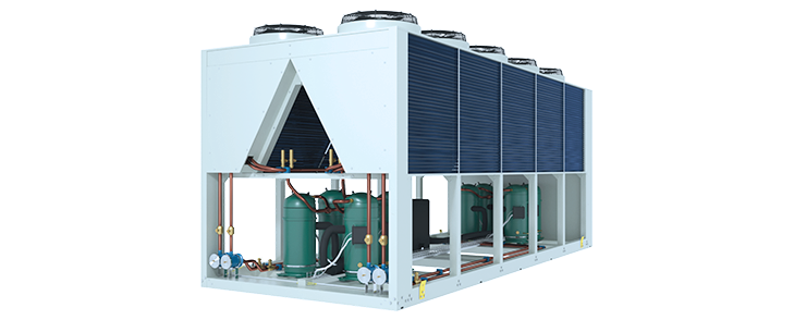
Blue Box – группа компаний, которая специализируется на разработке и изготовлении чиллеров бытового и промышленного типа. Первое предприятие Blue Box появилось в 1986 году, в Италии. Бренд сразу же стал известен: в отличие от конкурентов, компания начала оснащать технику винтовыми компрессорами, благодаря чему значительно снизила уровень шума.
Сегодня производитель оснащает свои чиллеры и вентиляционные системы теплообменниками пластинчатого типа, спиральными компрессорами и другими современными компонентами. Ее оборудование соответствует стандарту CE и требованиям каждой страны, куда оно поставляется. Среди отличительных особенностей чиллеров — возможность применения безопасного для человека и окружающей среды хладагента R407c.
В нашем сервисном центре давно работают с продукцией Blue Box. Мы обслуживаем и ремонтируем системы в короткие сроки (благодаря большому складу запчастей) и предоставляем годовую гарантию.

Зима
Готовь сани летом, а чиллер зимой!
- Приедем в день обращения
- Бесплатная диагностика
- Запчасти в наличии
Техническое обслуживание чиллера увеличивает срок службы и устраняет 80% всех неисправностей
Всё включено4990Р

Чистка и дезинфекция
Замена фильтров

Диагностика
Мелкий ремонт

Проверка герметичности
Дозаправка
Вызвать мастера
Прайс-лист на техническое обслуживание и ремонт
Фильтр быстрой диагностики отобразит в таблице наиболее вероятные неисправности, а также стоимость работ и запасных частей для их устранения
Сообщите мне модель чиллера BlueBox и симптомы неисправности
Я сразу назову наиболее вероятные причины и стоимость ремонта

Цена ремонта по телефону
за 30 секунд
Позвоните мне
или закажите обратный звонок

С 23 по 29 января
Мы выполнили 15 заказов
Постоянным клиентам
Мы помним о Вас

Скидка 10%
Получить скидку
Хотите заключить договор на постоянное обслуживание климатической техники? Это выгодно!
Приедем к Вам, сделаем точную оценку и оформим бумаги

или оставьте свой телефон

Обслуживаем бытовые и полупромышленные системы
-
Больше объект — больше скидка


Бесплатно
Полная антибактериальная обработка
при техобслуживании
в январе!
Заказать обслуживание
Клиенты довольны и рекомендуют нас
Потому что мы чиним чиллеры лучше и дешевле других

отзыв от клиента
Отремонтировали чиллер в помещении 200 кв.м в Москва Сити, ремонт прошел быстро и аккуратно без кучи мусора как это бывает, цена соответствует, так как обычно называешь площадь цена мгновенно взлетает, отдельное спасибо за рекомендации по уходу

отзыв от клиента
Выполнили ремонт чиллера в Видном. Получили то, что ожидали, как и должно быть в нормальной компании, все сделано профессионально, мастеру пять с плюсом, смело могу рекомендовать!

отзыв от клиента
Приглашали данных ребят для ремонта чиллера в офисе. Все четко, никаких претензий, приятное соотношение цена — качество!

отзыв от клиента
Это вторая организация, которую мы вызывали, первая сказали, что такой шум в чиллере вполне нормально, так как он старый, в общем обслужили, почистили, устранили запах, и чиллер снова как новый!

отзыв от клиента
Спасибо за оперативное устранение утечки фреона, была просьба сделать все максимально оперативно, с чем собственно и справились, теперь однозначно только к вам! Г. Химки.
Добавить отзыв

Москва, 1-я улица Ямского Поля, 17с1
Работаем без выходных с 8:00 до 22:00
-
Contents
-
Table of Contents
-
Troubleshooting
-
Bookmarks
Quick Links
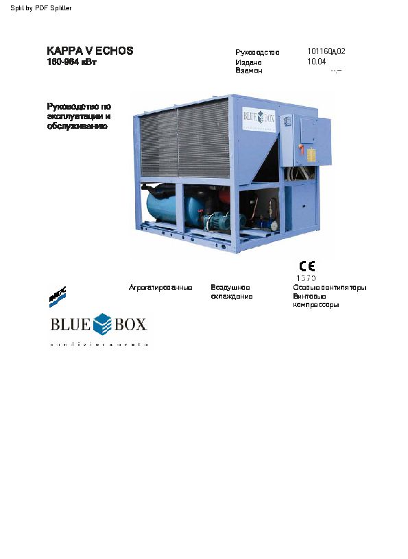
KAPPA V SR
635 ÷ 1065 kW
Installation, operating,
and maintenance
manual
Water chillers
Manual
Issue
Replaces
Air/water
self-contained
ISO 9001 — Cert. n. 0201
101070B02
02.03
06.02
0062
Axial fans and
screw compressors
Related Manuals for Blue Box KAPPA V SR
Summary of Contents for Blue Box KAPPA V SR
- Page 1
KAPPA V SR 101070B02 Manual 02.03 Issue 635 ÷ 1065 kW 06.02 Replaces Installation, operating, and maintenance manual 0062 Water chillers Air/water Axial fans and self-contained screw compressors ISO 9001 — Cert. n. 0201… -
Page 3: Table Of Contents
4.2.2 Spring Anti-Vibration Isolators WATER PIPING CONNECTIONS RECOMMENDED HYDRAULIC CIRCUIT DIAGRAM FOR KAPPA V SR HYDRAULIC CIRCUIT DIAGRAM VERSION KAPPA V SR /ST 2PS EVAPORATOR WATER PIPE CONNECTIONS FLEXIBLE JOINTS DESUPERHEATER HYDRAULIC CONNECTION (optional) HEAT RECOVERY EXCHANGER HYDRAULIC CONNECTIONS (OPTIONAL)
- Page 4
4.14 OPERATION WITH LOW TEMPERATURE CHILLED WATER AT EVAPORATOR TABLE 1 — FREEZING POINT FOR WATER-ANTIFREEZE MIXTURES OPERATING LIMITS EVAPORATOR PRESSURE DROP PUMPS AVAILABLE PRESSURE — MODEL KAPPA V SR /ST 2PS ELECTRICAL PANEL LAY OUT 4.15 ELECTRICAL CONNECTIONS 4.15.1 General 4.15.2… - Page 5
INTRODUCTION REPAIRING THE REFRIGERANT CIRCUIT 8.3.1 Leak test 8.3.2 High vacuum and dehydration of the refrigerant circuit 8.3.3 Refrigerant charge ENVIRONMENTAL CONSIDERATIONS TROUBLESHOOTING DECOMMISSIONING THE UNIT REFRIGERANT CIRCUIT OVERALL DIMENSIONS, WEIGHTS AND HYDRAULIC CONNECTIONS… -
Page 7: Kappa V Sr Water Chiller
KAPPA V SR water chiller UNIT FRAME Self supporting frame with removable panels, internally coated with expanded polyurethane sound-absorbing material; constructed from galvanized sheet steel with RAL 5014 powder paint baked at 180°C to provide a durable weatherproof finish. Threaded fasteners in stainless steel.
-
Page 8: Testing
KAPPA V SR /DC: unit with heat recovery condenser. In addition to the components of version KAPPA V SR this unit includes for each compressor a 100% heat recovery condenser for the production of hot water. The microprocessor automatically controls the water tempe- rature and the heat recovery safety switch.
-
Page 9: Hydraulic Circuit Accessories
— Set-point variable with remote signal (0-1 V, 0-10 V, 0-4 mA, 0-20 ma) VARIOUS ACCESSORIES — Rubber or spring type anti-vibration mounts — Anti-corrosion treatment of coils for use in aggressive environments — Timber crate packing — Pallet/skid for container shipment — Non-standard RAL paint colours Blue Box 3…
-
Page 10: Series
SERIES The KAPPA V SR series of water cooled chillers and heat pumps, are available in various sizes with capacities from 635 to 1.065 kW (capacities refer to water entering/leaving 12/7 °C, ambient air 35 °C) in the following basic versions:…
-
Page 11: Technical Data
TECHNICAL DATA Refrigerant R407C MODEL KAPPA V SR 65.2 73.2 80.2 84. 2 C o o l i n g ( * ) Nominal capacity 635,6 710,2 769,3 813,7 Evaporator water flow 30,37 33,93 36,76 38,88 109.316 122.150 132.323 139.963…
- Page 12
2.432 Shipping weight 7.681 7.632 7.816 8.576 (1) total water flow (*) ambient air temperature 35 °C; evaporator entering/leaving water temperature 12-7 °C;. (**) ambient air temperature 8 °C DB, 50%RH; condenser entering/leaving water temperature 40-45 °C. Blue Box 6… -
Page 13: Electrical Characteristics And Components
(2) maximum current before safety cut-outs stop the unit. This value is never exceeded and must be used to size the electrical supply cables and relevant safety devices (refer to electrical wiring diagram supplied with the unit). All values in brackets are refer to /ST version (units with storage tank) or units with pump. Blue Box 7…
-
Page 14: Technical Data — Kappa V Sr /St 2Ps
TECHNICAL DATA — KAPPA V SR /ST 2PS Refrigerant R407C M O D E L K A P P A V S R 65.2 73.2 80.2 84. 2 Pump section Evaporator water flow 30,37 33,93 36,76 38,88 109.316 122.150 132.323 139.963…
-
Page 15: Sound Pressure Levels
106.3 73,1 77,3 76,0 74,9 76,1 73,9 65,0 54,3 80,0 Lcc: sound pressure values measured in free field conditions with phonometer at 1 m from the unit and 1,5 m from ground levelon the condensing coil side. Blue Box 9…
-
Page 16: Field Of Application
Delivery Note which must be signed by both parties. Blue Box or their Agent must be informed, as soon as possible, of the extent of the damage.
- Page 17
(1) Side panel protection (not supplied) (2) Lifting holes Figure 1 Caution: ensure that the method of lifting does not allow the unit to slip from chains and slings or turn-over or slide from lifting devices. Blue Box 11… -
Page 18: Safety Precautions
— The compressor compartment contains various high temperature components. Adopt maximum caution when working in the vicinity of the compressors and avoid touching any parts of the unit without appropriate protection. — Do not work within the theoretical discharge trajectory of the relief valves. Blue Box 12…
-
Page 19: Mechanical Hazards
UNI EN 294. All the protections supplied to limit and enclose the fan compartments cannot be removed without the use of special tools. Blue Box 13…
-
Page 20: Thermal Hazards
Normal operating regime Contact with electrically live units designed built parts (direct contact). compliance with harmonised standard EN Elements carrying electrical 60204-1. Maintenance current in the case of faults. Inappropriate insulation. Radiated heat due to short- circuits or overloads. Blue Box 14…
-
Page 21: Refrigerant Safety Data — R407C
Personal precautions: Use personal protective equipment. Evacuate personnel to safe RELEASE MEASURES: areas. Do not breath vapours or spray mist. Ensure adequate ventilation. Methods for cleaning Shut off leaks it without risk. Solid evaporates. Ensure adequate ventilation. Blue Box 15…
- Page 22
S59 — Refer to manufacturer/supplier for information on recovery/recycling. Contaminated Do not reuse empty containers. Empty pressure vessels should be packaging: returned to supplier. 12. TRANSPORT No. O.N.U. 3340 INFORMATIQN: ADR/RID UN 3340 Refrigerant gas R407C, 2, 2° A, ADR/RID Label: 2 Blue Box 16… -
Page 23: Positioning
— possible sound reverberation. All models in the KAPPA V SR series are designed for exterior installation: to avoid the risk of air recirculation units must not be covered by a shelter roof or located under trees (even if the unit is only partially covered).
- Page 24
The units should not be installed next to offices, bedrooms, or other areas where low noise levels are a necessity. To avoid excess sound reverberation do not install the units in narrow or confined spaces. Figure 3 Blue Box 18… -
Page 25: Installation
High walls near the machine may interfere with correct functioning. When units are side by side the minimum distance between them should be 3 metres (see figure 4). SIDE BY SIDE UNITS 3 m min. 0.75 m (*) 1.5 m Figure 4 Blue Box 19…
-
Page 26: Anti-Vibration Isolators (Option)
The load of the unit is and two bolts and washers. supported by the full surface of the isolators. The load is not exerted on the bolt. Figure 6 Blue Box 20…
-
Page 27: Water Piping Connections
— Vent valves, to be installed in the upper parts of the circuit, for air bleeding. — Expansion device with accessories for circuit pressurisation, water thermal expansion compensation and system filling. — Unload valve and if necessary drainage tank for circuit emptying during maintenance and seasonal stop. Blue Box 21…
-
Page 28: Recommended Hydraulic Circuit Diagram For Kappa V Sr
Blue Box 22…
-
Page 29: Hydraulic Circuit Diagram Version Kappa V Sr /St 2Ps
HYDRAULIC CIRCUIT DIAGRAM VERSION KAPPA V SR /ST 2PS Blue Box 23…
-
Page 30: Evaporator Water Pipe Connections
It is mandatory to install a flow switch (supplied with the unit) on the evaporator water outlet connection identified by the following decal: EVAPORATOR WATER It is compulsory to install a metallic filter, on the water inlet piping. If a filter is not installed the warranty will be terminated immediately. Blue Box 24…
-
Page 31: Flexible Joints
4) Line up the connection and the counter-connection, place the gasket in the original position and if possible lubricate it on contact areas with a non-aggressive oil or grease. 5) Assemble the joint and tighten the nuts. Joint Gasket Figure 7 Blue Box 25…
-
Page 32: Desuperheater Hydraulic Connection (Optional)
RECOVERY WATER Heat recovery water outlet: RECOVERY WATER On HP version units the hydraulic connection to the desuperheater must be isolated during heat pump operation Entering/leaving chilled water Desuperheater recovery water outlet Desuperheater recovery water inlet Figure 8 Blue Box 26…
-
Page 33: Heat Recovery Exchanger Hydraulic Connections (Optional)
30 °C. DIAGRAM WITH 3-WAY VALVE 3-way valve Recovery water outlet Recovery water inlet Figure 9 Blue Box 27…
-
Page 34: Pressure Relief Valves
The vent pipe must be sized no smaller than the relief valve and it must not be supported from the valve. Caution: The relief valve must be directed into a safe zone where no injuries can be caused to people. Blue Box 28…
-
Page 35: Water Flow Rate To Evaporator
This control is calibrated and factory tested. Warning: speed control calibration settings must not be altered. If it proves necessary to alter speed calibration settings, this task must be entrusted to a skilled engineer, who should refer to the attached instruction sheet. Blue Box 29…
-
Page 36: Operation With Low Temperature Chilled Water At Evaporator
In the case of ST versions with a glycol content greater than 30% pumps with special seals must be specified at the time of the order. Blue Box 30…
-
Page 37: Operating Limits
OPERATING LIMITS KAPPA V SR — Refrigerant R407C Refrigeratore / Chiller Con dispositivi opzionali per basse Raffreddamento temperature dell’aria esterna. Cooling With low ambient temperature kit. Ambient air temperature [°C] Pompa di calore Heat pump Riscaldamento Heating Con dispositivi opzionali per basse Raffreddamento temperature dell’aria esterna.
-
Page 38: Evaporator Pressure Drop
EVAPORATOR PRESSURE DROP 73.2 80.2 100.2 106.3 65.2 84.2-88.2-93.2 Portata acqua [l/s] Water Flow [ l / s ] The water temperature rise for all versions must be between 3 °C (min) and 8 °C (max) Blue Box 32…
-
Page 39: Pumps Available Pressure — Model Kappa V Sr /St 2Ps
PUMPS AVAILABLE PRESSURE — MODEL KAPPA V SR /ST 2PS PREVALENZA UTILE 93.2 84.2-88.2 65.2-73.2 100.2 80.2 106.3 Portata acqua [l/s] Water flow [l/s] Water flow Blue Box 33…
-
Page 40: Electrical Panel Lay Out
ELECTRICAL PANEL LAY OUT MODELS 65.2 — 100.2 Blue Box 34…
- Page 41
ELECTRICAL PANEL LAY OUT MODEL 106.3 Remote electric panel Option — ST version See sheet 2 Blue Box 35… - Page 42
FUSES CAPAC. POW. FACT. CORRECT. COMPR. 1 RELAIS START 3 FU42 FUSES CAPAC. POW. FACT. CORRECT. COMPR. 2 MAIN SWITCH FU46 FUSES CAPAC. POW. FACT. CORRECT. PUMPS TEMPERATURE SENSOR FU50 FUSES AUX. TRANSFORMER AUX. TRANSFORMER FU51 AUX. CIRCUIT FUSES FU52 FUSE CONTROL Blue Box 36… -
Page 43: Electrical Connections
Line voltage fluctuations must not be more than ±5% of the nominal value, while the voltage unbalance between one phase and another must not exceed 2%. If these tolerances are not possible contact Blue Box to provide the necessary devices.
-
Page 44: Potential Free Contacts
4.15.6 RS485 serial interface (optional) All KAPPA V SR units can be equipped with a serial interface board for supervision or remote diagnostics functions by means of a computer. The serial interface board plugs into a dedicated slot on the connection board.
-
Page 45: User Interface — Microprocessor Pco
“Clock” key: press this key to open the clock menus. “Set” key: this key opens the menus in which the various operating set-points can be edited. “Prog” key: this key opens the service menus. Blue Box 39…
- Page 46
Arrow key: the arrow keys allow you to navigate through the menus; when an editable field is selected, the arrow keys serve to change the current value. “Enter” key: pressing this key allows you to access fields containing editable parameters and also to confirm any changes you make to such parameters. Blue Box 40… -
Page 47: Start-Up
In this condition the display shows the values of the various machine parameters, but compressor is inhibited. When in stand-by mode the unit can be powered on. Power-on is obtained by pressing the “ON-OFF” button of the microprocessor control or via serial or an external interlock. Blue Box 41…
-
Page 48: Enabling The Unit
The low temperature water alarm can only be activated when the unit is switched on (in stand-by conditions the freeze alarm is not operational). 5.2.9 Evaporator anti-freeze protection electric heater (optional) Blue Box 42…
-
Page 49: Compressor Operation
With the start rotation function active, the first compressor to start is the first one that previously stopped. The first compressor to start will be the one with the least operating hours. The capacity control of compressors can be carried out either by steps or continuously. Blue Box 43…
-
Page 50: High And Low Pressure Alarms
The evaporation control is active only during heating mode operation. Depending on the ambient air temperature and humidity conditions, condensate or frost will tend to form, consequently obstructing the free passage of air and causing thermal insulation. The frost that builds up on the Blue Box 44…
-
Page 51: Total Heat Recovery (Option)
The valves are sized on the basis of the temperature values specified at the time of the order. The machine operating limits shown in the catalogue are not affected. If the hydraulic circuit contains glycol in sufficient Blue Box 45…
-
Page 52: Operation Leaving Water Temperature Control (Option)
Disconnect the unit from the power supply only in the event of prolonged disuse (e.g. seasonal shutdowns). For temporary shutdown of the unit refer to the guide lines given in paragraph 5.6. Blue Box 46…
-
Page 53: Stopping The Unit
5.5 EMERGENCY STOP Emergency stops are obtained by turning the red colour main disconnect switch on the electrical panel to position 0. (figure 14). Figure 14 Blue Box 47…
-
Page 54: Checks During Operation
(saturation temperature corresponding to condenser delivery pressure); for units charged with R407C refrigerant, refer to the B.P. (Bubble Point) pressure gauge scale. The difference between the temperature values measured in this manner is equivalent to the subcooling value. Blue Box 48…
-
Page 55: Calibration Of Control Equipment
Minimum pressure switch setting 2.5 / 0.7 * manual (from controller) Evaporator heater setting °C automatic Defrost start setting automatic Defrost end setting automatic Defrost end thermostat setting °C automatic Defrost pressure switch setting automatic * Chiller / heat pump Blue Box 49…
-
Page 56: Maintenance And Periodic Checks
Check the colour of the sight glass core (green = no moisture, yellow = moisture every 4 months present): if it is yellow change the refrigerant filter Check that the noise level has not increased. every 4 months Blue Box 50…
-
Page 57: Repairing The Refrigerant Circuit
— Repeat the operation described above. — Repeat the operation described above for the third time in order to reach the highest degree of vacuum possible. This procedure should guarantee the elimination of up to 99% of contaminants. Blue Box 51…
-
Page 58: Refrigerant Charge
Refrigerant R407C is mentioned among substances subject to special monitoring regimes established by law, and as such they are subject to the prescriptions indicated above. Use special care during maintenance work in order to limit the risk of refrigerant leakage as far as possible. Blue Box 52…
-
Page 59: Troubleshooting
We therefore recommend that Blue Box or other skilled HVAC engineers are contacted to identify and correct the problem.
- Page 60
No compressor No consent from Activate operation from running. Display On: supervision system supervision system ”OFF from supervision system” No compressor ⊗ ⊗ No consent from “on/off” Press “on/off” key running. Display On: key of user interface ”OFF” Blue Box 54… - Page 61
Check voltage stability and fit running. Display On: voltage appropriate protection if unit ON with alarm necessary “Thermal protections Compressor 1, 2, 3” ⊗ ⊗ Setting of thermal Contact assistance protections ⊗ ⊗ Circuits partially discharged Call service to replenish charge Blue Box 55… - Page 62
⊗ Faulty controller Contact service organisation ⊗ Defrost sensor short circuit Contact service organisation No compressor ⊗ Excessive thermal load Reduce thermal load running. Display On: unit ON with alarm “Exceeded Threshold Low Temperature User Water Reference” Blue Box 56… - Page 63
⊗ Incorrect phase sequence Invert two of the phase wires of running. Display On: the power supply line unit OFF with alarm ”Incorrect Phase Sequence” and phase sequence relay with green LED On and orange LED Off Blue Box 57… - Page 64
Unit at temperature Normal operation ⊗ ⊗ Compressor fuses burnt- Check continuity of fuses; if burnt-out call service ⊗ ⊗ Controller faulty Call service ⊗ ⊗ Anti-recycle timer running Wait 5 minutes until the timer generates a consent Blue Box 58… - Page 65
Liquid refrigerant valve not Check and open fully completely open ⊗ ⊗ Pressostat faulty Check; replace if necessary ⊗ ⊗ One or more Problems at the compressor Call service organisation compressors switched off. Display On with alarm “Compressor Thermal Protections” Blue Box 59… - Page 66
Call service organisation discharged ⊗ Liquid refrigerant filter Clean or replace clogged ⊗ ⊗ Controller not working Call service organisation ⊗ 4-way reversing valve not Check power supply and energised solenoid valve coils and replace if necessary Blue Box 60… - Page 67
Casing panels vibrate Check that panels are properly fastened; contact service organisation if necessary ⊗ ⊗ Worn fan bearings Check; replace fan if necessary If the display presents alarms other than those described above, contact the service organisation. Blue Box 61… -
Page 68: Decommissioning The Unit
This procedure is designed to assist the work of collection, disposal, and recovery specialists and to reduce the associated environmental impact. Blue Box 62…
-
Page 69: Refrigerant Circuit
REFRIGERANT CIRCUIT KAPPA V SR ≠ ≠ Blue Box 63…
- Page 70
REFRIGERANT CIRCUIT KAPPA V SR /HP ≠ ≠ Blue Box 64… - Page 71
REFRIGERANT CIRCUIT KAPPA V SR /DC ≠ ≠ Blue Box 65… -
Page 72: Overall Dimensions, Weights And Hydraulic Connections
OVERALL DIMENSIONS, WEIGHTS AND HYDRAULIC CONNECTIONS KAPPA V SR — KAPPA V SR/HP Models 65.2 — 73.2 Blue Box 66…
- Page 73
OVERALL DIMENSIONS, WEIGHTS AND HYDRAULIC CONNECTIONS KAPPA V SR — KAPPA V SR/HP — FOOTPRINT Models 65.2 — 73.2 Blue Box 67… - Page 74
OVERALL DIMENSIONS, WEIGHTS AND HYDRAULIC CONNECTIONS KAPPA V SR — KAPPA V SR/HP Models 80.2 — 88.2 Blue Box 68… - Page 75
OVERALL DIMENSIONS, WEIGHTS AND HYDRAULIC CONNECTIONS KAPPA V SR — KAPPA V SR/HP — FOOTPRINT Models 80.2 — 88.2 Blue Box 69… - Page 76
OVERALL DIMENSIONS, WEIGHTS AND HYDRAULIC CONNECTIONS KAPPA V SR — KAPPA V SR/HP Models 93.2 — 100.2 Blue Box 70… - Page 77
OVERALL DIMENSIONS, WEIGHTS AND HYDRAULIC CONNECTIONS KAPPA V SR — KAPPA V SR/HP — FOOTPRINT Models 93.2 — 100.2 Blue Box 71… - Page 78
OVERALL DIMENSIONS, WEIGHTS AND HYDRAULIC CONNECTIONS KAPPA V SR — KAPPA V SR/HP Model — 106.3 Blue Box 72… - Page 79
OVERALL DIMENSIONS, WEIGHTS AND HYDRAULIC CONNECTIONS KAPPA V SR — KAPPA V SR/HP — FOOTPRINT Model — 106.3 Blue Box 73… - Page 80
Blue Box 74… - Page 82
BLUE BOX srl is an associate company of BLUE BOX GROUP BLUE BOX srl Via E. Mattei, 20 35028 Piove di Sacco PD Italy Tel. +39.049.9716300 Fax +39.049.9704105 BLUE BOX GROUP www.blueboxgroup.it Info@blueboxgroup.it Manual 101070B02 — Issue 02.03 / Replaces 05.02…
Бренд: Blue Box
Категория для инструкций: Кондиционеры промышленные и VRF-системы
Алфавит (англ.): B
Описание: Чиллеры Blue Box серии ZETA 2002 (38 — 266 кВт) с воздушным охлаждением конденсатора, осевыми вентиляторами игерметичными спиральными компрессорами. Инструкции по монтажу, эксплуатации и техническому обслуживанию
Размер файла: 1517121 байт
Инструкции на чиллеры Blue Box серии ZETA с воздушным охлаждением конденсатора


В отличие многочисленных типов промышленного оборудования, обслуживание чиллеров Blue Box является важным для обеспечения нормальной работоспособности устройств. Это связано с тем, что через климатические устройства проходит огромных объем воздушных масс, из-за чего внутри остается влага, пыль, различные микроорганизмы. Кроме этого, внутренние элементы изнашиваются за короткий период, так как постоянно в ходе работы они находятся в движении, тогда как составляющие вешнего блока подвергаются воздействию высоких и низких температур.
Возможные ошибки и неполадки в рабочем процессе оборудования позволяет выявить грамотная диагностика чиллера Blue Box, которая наряду с профилактическими работами входит в спектр услуг СЭТКУЛ. После ее осуществления наши мастера приступают к ремонту чиллера Блю Бокс. Можете быть уверены, что после определения причины неполадок профессионалы компании предпримут все необходимые меры, чтобы найти подходящий способ решения вопроса, при этом любые работы осуществляются строго по согласованию с клиентом.