
Содержание
- Kyocera ошибка соединения 0x2101 smtp
- Устранение ошибок передачи и соединения на принтерах Kyocera
- Что значит такая ошибка: информация из руководства
- Когда возникает
- Возможные причины сбоев
- Правильная настройка
- Другие ошибки и их решение
- Устранение ошибки передачи – Инструкция по эксплуатации Kyocera Ecosys m2040dn
- Страница 367
- Kyocera ошибка соединения 0x2101 smtp
- Thread: KM-5050 Scan to SMB Error 2101
- KM-5050 Scan to SMB Error 2101
- Re: KM-5050 Scan to SMB Error 2101
- Re: KM-5050 Scan to SMB Error 2101
- Re: KM-5050 Scan to SMB Error 2101
Kyocera ошибка соединения 0x2101 smtp

Код ошибки:4701,
5101, 5102, 5103, 5104,
7102, 720f
Выключите и затем включите
главный включатель питания. Если
эта ошибка возникнет повторно,
запишите код ошибки, который
отображается на дисплее
сообщений, и обратитесь к
специалисту по обслуживанию.
(См. процедуру в Сбой аппарата
Вызовите сервисный
персонал.)
Возможно, отсканированы
999 страниц оригиналов?
Если число страниц оригинала
превышает 999, передавайте
страницы отдельными пакетами.
Код ошибки при сканировании с отправкой по Email
Возможно, неправильное
имя сервера SMTP/POP3?
Установите правильное имя
сервера в COMMAND CENTER.
Возможно, вы указали
недопустимые имя
пользователя или пароль?
Введите правильные имя
пользователя и пароль.
Указали ли вы адрес
адресата?
Укажите адрес адресата.
Включен ли протокол
SMTP?
Включите протокол SMTP в
COMMAND CENTER.
Код ошибки:2101,
2102, 2103, 2201, 2202,
2203
Выбрано ли «Другая
аутентификация», когда
выполняется
аутентификация POP
перед SMTP?
Выберите действующего
пользователя POP3,
отличающегося от «Other».
Является ли указанный
сервер сервером SMTP?
Установите правильное имя
сервера в COMMAND CENTER.
Правильно ли выполнено
подключение к сети?
Убедитесь, что сетевой кабель
правильно подключен.
Убедитесь, что сетевая среда
(сервер, концентратор или другая
сеть LAN) работает правильно.
Не пытаетесь ли вы
передать слишком
большой объем данных?
Измените размер, который можно
передавать, в COMMAND
CENTER.
Источник
Ошибки передачи (1102, 1101, 2101) и соединения (0×1102) на принтерах Kyocera происходят из-за неправильной настройки, сетевых сбоев, неправильного ввода данных авторизации при подключении к папке на удаленном ПК.
Основной способ устранения сбоя – правильная настройка оборудования. Необходимо указать нужные параметры на печатающем устройстве и на компьютере, через который выполняется удаленное сканирование.
Что значит такая ошибка: информация из руководства
Неисправность возникает во время передачи документа в папку на удаленном ПК. Код 1102 или 1103 говорят, что принтер не получил доступ из-за неправильного ввода пары логин-пароль или адреса компьютера.
На устройствах Kyocera в случае такого сбоя отображается сообщение «Login to the host has failed». Также возможно появление надписи «Connection Error».
Когда возникает
На принтерах и МФУ ошибка вылетает в таких ситуациях:
- Работе через SMB или FTP сервер.
- Отправке электронных писем из-за ввода неактуальных username или пароля для сервера SMTP либо POP3.
Возможные причины сбоев
Причиной могут быть следующие факторы:
- Периодическое или постоянное отсутствие доступа к сети.
- Недопустимое число символов в названии устройства, логине, пароле.
- Указаны неполный домен, пользовательское имя.
- Путь к сетевой директории прописан неверно.
Неправильная настройка брандмауэра: наличие задач с более высоким приоритетом.
Правильная настройка
Для устранения неисправности нужно правильно настроить оборудование. Сначала проверьте параметры на компьютере, затем на печатающем устройстве.
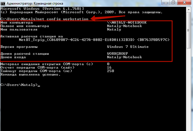
Проверьте, правильно ли указано имя ПК, доменный адрес и username. Для этого введите в командной строке «net config workstation».
Убедитесь, что правильно указан путь к сетевой папке. Его можно посмотреть в свойствах.
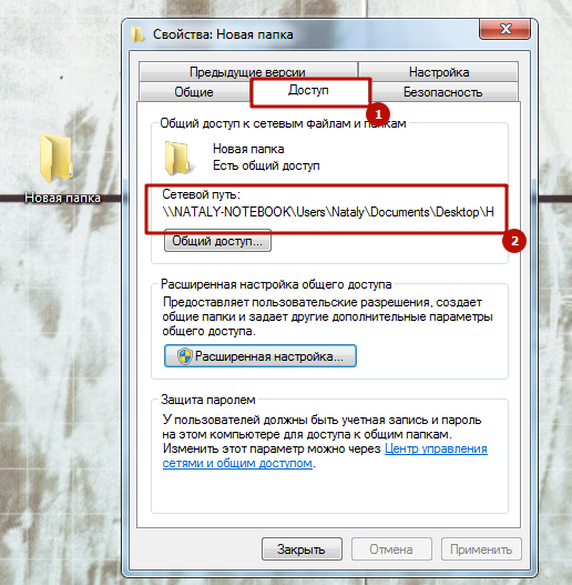 Windows 7
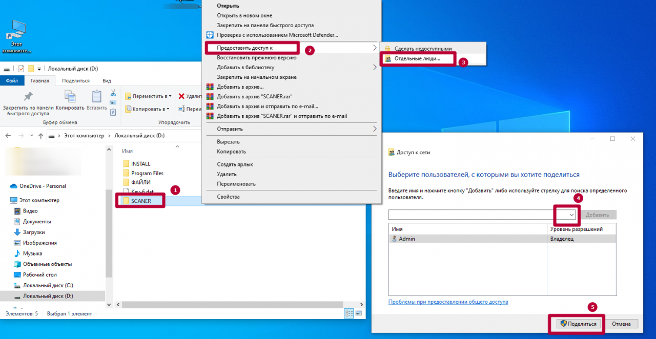 Windows 10
Включите общий доступ для файлов и принтеров. Это можно сделать в «Центре управления сетями», во вкладке «Дополнительные параметры общего доступа».
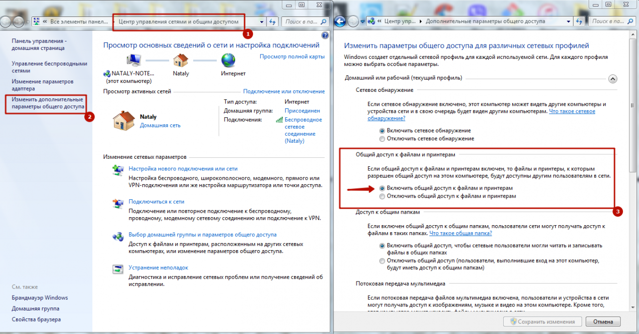 Windows 7
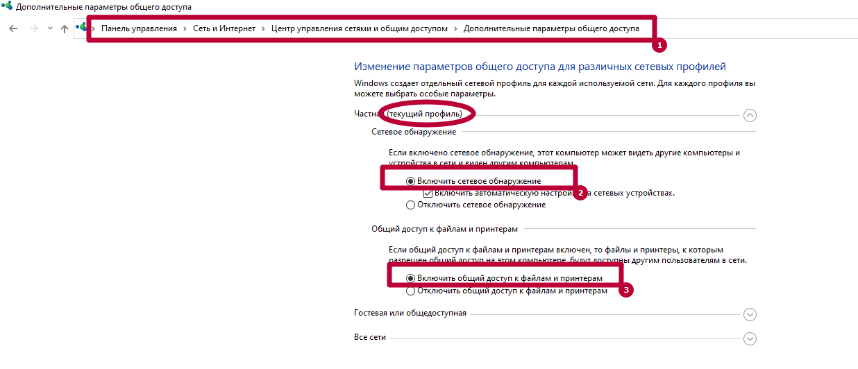 Windows 10
Убедитесь, что на МФУ включены протоколы FTP и SMB. Это можно сделать через интерфейс Command Center. Отправьте оригинал документа, выбрав направление обмена данными.
Укажите имя компьютера и название папки, открытой для общего доступа. Пропишите актуальные данные авторизации для входа на ПК. После проверки подтвердите операцию, нажав «Старт».
Другие ошибки и их решение
На МФУ также могут появиться похожие сбои. Наиболее распространенные – 1103 и 1105.
Появляется при передаче через SMB либо FTP сервер из-за неправильно указанного имени пользователя либо пароля. Также появляется при отсутствии прав доступа к сетевой папке.
Возникает, если в Command Center на Kyocera не включена функция передачи через FTP, SMB или SMTP сервер. В этом случае необходимо задать значение в настройках принтера.
Источник
Устранение ошибки передачи – Инструкция по эксплуатации Kyocera Ecosys m2040dn
Страница 367
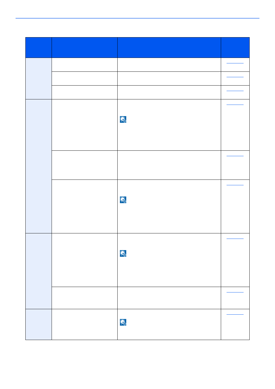
Устранение неисправностей > Устранение неисправностей
Устранение ошибки передачи
Меры по устранению
Не удалось отправить
электронную почту.
Проверьте правильность имени хоста SMTP
сервера в Command Center RX.
Не удалось отправить через
FTP.
Проверьте имя хоста FTP.
Не удалось отправить через
SMB.
Проверьте имя хоста SMB.
Не удалось отправить через
SMB.
Проверьте настройки SMB:
•
имя пользователя и пароль при входе.
Если отправитель является пользователем
домена, укажите имя домена:
•
Не удалось отправить
электронную почту.
Проверьте следующее на Command Center RX:
•
имя пользователя и пароль для сервера SMTP;
имя пользователя и пароль для сервера POP3;
предел размера сообщения эл. почты.
Не удалось отправить через
FTP.
Проверьте настройки FTP-сервера:
•
имя пользователя и пароль при входе.
Если отправитель является пользователем
домена, укажите имя домена:
право доступа получателя к папке.
Не удалось отправить через
SMB.
Проверьте настройки SMB:
•
имя пользователя и пароль при входе.
Если отправитель является пользователем
домена, укажите имя домена:
право доступа получателя к папке.
Не удалось отправить через
FTP.
Проверьте настройки FTP-сервера:
•
право доступа получателя к папке.
Не удалось отправить
электронную почту.
Проверьте адрес электронной почты.
Если адрес отклонен доменом, отправка
электронного письма невозможна.
Источник
Kyocera ошибка соединения 0x2101 smtp
Для сканирования и отправки документов по e-mail для МФУ М2835dw необходимо не только наполнить адресную книгу, но и настроить отправку почты по e-mail. Для реализации этой возможности нужно настроить параметры почтовых протоколов, благодаря которым почта будет отправляться на выбранные адреса.
Для настройки отправки почты придется пройтись по меню аппарата, перепрыгивая с одного окна на другое. Над удобством меню, как и над логикой управления инженерам kyocera явно стоит поработать. Перед настройкой необходимо создать пользователя на любом почтовом сервере. В данном случае был создан пользователь Адрес электронной почты защищен от спам-ботов. Для просмотра адреса в вашем браузере должен быть включен Javascript. (на почтовом сервере yandex).
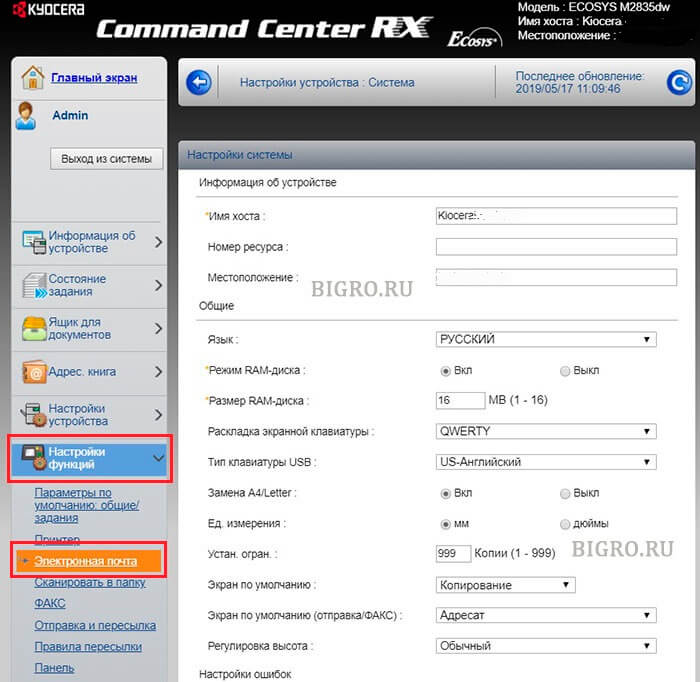
1. Открываем веб-панель МФУ Ecosys Kyocera M2835dw, набираем логин, пароль (по умолчанию Admin — Admin).
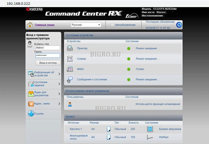
2. Далее переходим «Настройки функций» — «Электронная почта«.
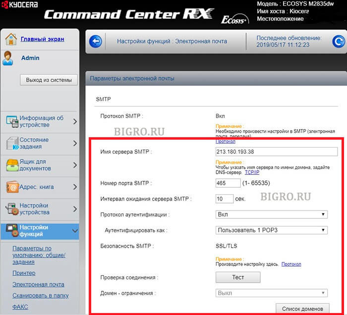
3. В открывшемся окне заполняем:
Имя сервера SMTP: 213.180.193.38
Имя севера SMTP (сервер исходящей почты) зависит от используемого почтового сервера. В данном случае IP-адрес почтового сервера по протоколу smtp 213.180.193.38 (smtp.yandex.ru). Посмотреть настройки основных почтовых серверов можно ЗДЕСЬ.
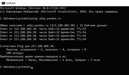
Имя сервера SMTP лучше задать по имени (например, для Yandex — smtp.yandex.ru), но если в сети не работает DNS, то МФУ не будет понимать, что такое smtp.yandex.ru. Проверить можно набрав в командной строке: ping smtp.yandex.ru. Если будет ответ от сервера (пройдут пинги), то можно прописать имя почтового сервера по протоколу smtp, если пинги не пройдут, тогда указываем IP-адрес.
Номер порта smtp: 465.
В данном случае используется шифрование, данный порт используется на почтовом сервере Yandex по протоколу SMTP.
Протокол аутентификации: Вкл.
Аутенфицировать как: Пользователь 1 POP3.
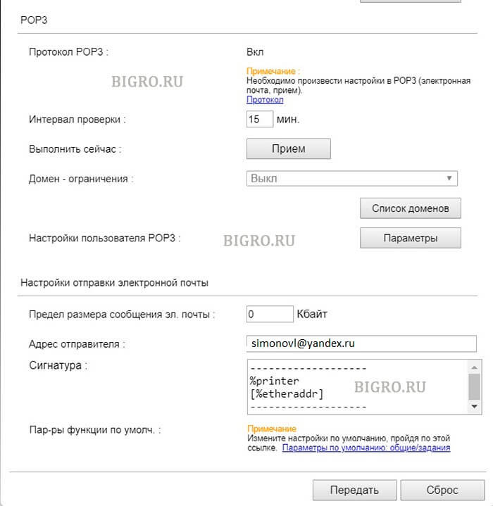
4. В секции «Настройки отправки электронной почты» настраиваем:
Адрес отправителя: Адрес электронной почты защищен от спам-ботов. Для просмотра адреса в вашем браузере должен быть включен Javascript. .
Адрес отправителя — созданный почтовый аккаунт.
Нажимаем «Передать» для сохранения настроек. Далее в секции «POP3» нажимаем кнопку «Параметры» («Настройки пользователя POP3«).
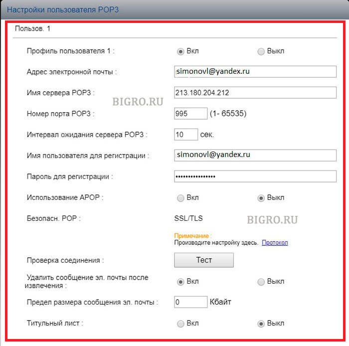
5. В окне «Настройки пользователя POP3«:
Профиль пользователя 1: Вкл.
Адрес электронной почты: Адрес электронной почты защищен от спам-ботов. Для просмотра адреса в вашем браузере должен быть включен Javascript. .
Адрес электронной почты — созданный почтовый аккаунт.
Имя сервера POP3: 213.180.204.212
Имя севера POP3 (сервер входящей почты) зависит от используемого почтового сервера. В данном случае IP-адрес почтового сервера по протоколу pop3 213.180.204.212 (pop.yandex.ru). Посмотреть настройки основных почтовых серверов можно ЗДЕСЬ.
Имя сервера POP3 лучше задать по имени (например, для Yandex — pop.yandex.ru), но если в сети не работает DNS, то МФУ не будет понимать, что такое pop.yandex.ru. Проверить можно набрав в командной строке: ping pop.yandex.ru. Если будет ответ от сервера (пройдут пинги), то можно прописать имя почтового сервера по протоколу POP3, если пинги не пройдут, тогда указываем IP-адрес.
Номер порта POP3: 995.
В данном случае используется шифрование, данный порт используется на почтовом сервере Yandex по протоколу POP3.
Имя пользователя для регистрации Адрес электронной почты защищен от спам-ботов. Для просмотра адреса в вашем браузере должен быть включен Javascript. .
Имя пользователя для регистрации — созданный почтовый аккаунт.
Нажимаем «Передать» для сохранения настроек. Далее нажимаем «Протокол» (Примечание: Произведите настройку здесь).
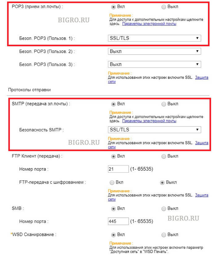
6. В новом окне настраиваем:
POP3 (прием эл. почты): Вкл.
Безоп. POP3 (Пользов. 1): SSL/TLS.
SMTP (передача эл. почты): Вкл.
Безопасность SMTP: SSL/TLS.
Нажимаем «Передать» для сохранения настроек. Далее нажимаем «Защита сети» (Примечание: Для использования этих настроек включите SSL).
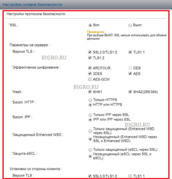
7. В открывшемся окне «Настройки сетевой безопасности» включаем SSL:
SSL: Вкл.
Нажимаем «Передать» для сохранения настроек.
7. Далее переходим в «Настройки электронной почты» (Настройки функций — Электронная почта), в секции SMTP нажимаем кнопку «Тест«. При успешном соединении появится сообщение «Соединение ОК». Это значит, что настройки произведены правильно. Теперь можно сканировать документы и передавать по электронной почте выбранным в адресной книге адресатам.
Источник
Thread: KM-5050 Scan to SMB Error 2101
Thread Tools
Display
KM-5050 Scan to SMB Error 2101
Hello everyone,
I have a KM-5050 with firmware version 2GR_2000.014.028 2007.11.02,
Print works ok.
Trying to hook it up to scan to a folder (via SMB) on Windows Server 2008 R2 Data Center.
Scan to email is also working. I have tried using the hostname and IP address. The username and password is also a domain admin account.
For testing, when hooking it up to an individual laptop, the scan to SMB folder works ok.
Is there any suggestion anyone may know about to get this working?
Is my firmware the culprit?
Thanks in advance for your help.
Claudio
Re: KM-5050 Scan to SMB Error 2101
I remember seeing something like this before. When you put in the username info you need to add the domain info as well. I for the life can’t remember where I saw this but I’ll look around in some stuff I have around and see if I can find it.
update found the info in the Kyocera Scan to SMB(PC) set up guide. check this
Check the information in “domain nameuser name” format for logging onto Windows.
1 Press the Ctrl-Alt-Delete key combination on the
keyboard.
2 Check the Logon Information that appears on the
Windows Security window. In the sample window
below, “ABCDNETjames.smith” corresponds to
“domain nameuser name”.
(Example: ABCDNET james.smith)
Service Manager 1,000+ Posts 

 Join Date Feb 2010 Posts 1,910 Rep Power 71
I think 2101 implies a firewall/anti virus issue
Master Of The Obvious 10,000+ Posts
 Join Date Jul 2007 Location Lapeer, Michigan Posts 21,181 Rep Power 422
Re: KM-5050 Scan to SMB Error 2101
You can get 2101 for a hostname IP issue, or a login/password issue. Either one.
For the sake of diagnosis, I’d suggest creating a new user with a new known password, and new admin properties. Most times it’s login/password related, even if you can log in to the PC/server with this info sometimes it won’t work from the MFP. Many times this has resolved 2101 errors. =^..^=
Re: KM-5050 Scan to SMB Error 2101
Totally agree with this solution, I have a story
Call out to the Customer, 2 local Meath GAA players (Gaelic football) for top tray malfunction on a Kyocera model /Utax 1625. I cleaned the machine located the problem as the try paper size guide was broke etc. I taught I was done, when the Customer told me that the machine won’t print or scan.
I re-installed drivers etc., put in all the scan data and tried to scan ERROR 2101 kept coming up. So out to the car and plugged in the laptop and print and scan function working 100%. I asked the Customer any changes recently and they said the router so I inspect and its fine. I then check the only Pc connected to the machine and give it a good going over. I find the McAfee anti-virus software and disable it and hooray I can print but no scan. I ask the Customer was the anti-virus updated and he said no, shortly after my SM rang because I was there 1.5 hours I explained what happened and he told me to just get going.
I tell the Customer that I must go but would be back with the rtf parts that my SM has been on and that they should have logged the call regarding the print and scan, as I was only into my 2nd year and that call would require a more exp Tech and that if they wanted to print they must either disable or change their settings in the Anti-virus to allow printing. I was not long gone when the Customer called the Office giving out saying I was hopeless etc. and yes my SM called the Customer and asked was the Anti-Virus changed, when he finished that call he gave me the hairdryer treatment. I told him that when I finished the call they wanted me to look at the printing etc., I told him it was the Anti-Virus blocking the printing and he still fumed and sent my Supervisor there. The Supervisor rang me and I told him the story and he came back with a report that the Router was faulty and told the Customer to change it.
It was less than a week and the Customer was raging, the router did not work. The call was logged and the SM sent out his golden boy, the Polish Master who was a lazy git TBH, I have to admit he was there for 3 hours and solved the problem. It was the anti-virus, and yes they had recently got an IT guy in to install it. I was never thanked for attempting the repair but the Customer was charged for the call out and not telling anyone about the change. SUCKER
Источник
- Code: C0030
- Description: FAX PWB system error
- Causes: The FAX processing cannot be continued due to the FAX firmware error.
- Remedy: 1 Resetting the main power The FAX PWB does not operate properly. Turn off the power switch and the main power switch. After 5 seconds, turn on the main power switch and the power switch.
2 Firmware upgrade The firmware is faulty. Reinstall the FAX firmware.
3 Replacing the FAX PWB The FAX PWB is faulty. Replace the FAX PWB.
- Code: C0060
- Description: Engine PWB communication error
- Causes: Error was detected at the initial communication of the engine PWB
- Remedy: 1 Resetting the main power The engine PWB does not operate properly. Turn off the power switch and the main power switch. After 5 seconds, turn on the main power switch and the power switch.
2 Checking the connection The connector is not properly connected. Clean the engine PWB connector (YC17) and reconnect it.
3 Firmware upgrade The firmware is not the latest version. Upgrade the firmware to the latest version.
4 Replacing the engine PWB The engine PWB is faulty. Replace the engine PWB and then execute U411 [Table(ChartA)].
- Code: C0070
- Description: FAX PWB incompatible detection error
- Causes: Abnormal detection of FAX control PWB incompatibility in the initial communication with the FAX control PWB, any normal communication command is not transmitted.
- Remedy: 1 Checking the FAX PWB The incompatible FAX PWB is installed. Install the FAX PWB for the applicable model.
2 Firmware upgrade The FAX firmware is faulty. Reinstall the FAX firmware.
3 Replacing the main PWB The main PWB is faulty. Replace the main PWB.
- Code: C0100
- Description: Backup memory device error
- Causes: An abnormal status is output from the flash memory.
- Remedy: 1 Resetting the main power The flash memory does not operate properly. Turn off the power switch and the main power switch. After 5 seconds, turn on the main power switch and the power switch.
2 Checking the main PWB The connector or the FFC is not connected properly. Or, the wire, FFC, the PWB is faulty. Clean the terminal of the connectors on the main PWB, reconnect the connector of the wire, and reconnect the FFC terminal. If the wire or the FFC is faulty, repair or replace them. If not resolved, replace the main PWB.
- Code: C0120
- Description: MAC address data error
- Causes: The MAC address data is incorrect.
- Remedy: 1 Resetting the main power The flash memory does not operate properly. Turn off the power switch and the main power switch. After 5 seconds, turn on the main power switch and the power switch.
2 Checking the MAC address The MAC address is incorrect. Replace the main PWB when the MAC address is not indicated on the network status page.
- Code: C0130
- Description: Backup memory reading/writing error
- Causes: The reading or writing into the flash memory is unavailable.
- Remedy: 1 Resetting the main power The flash memory does not operate properly. Turn off the power switch and the main power switch. After 5 seconds, turn on the main power switch and the power switch.
2 Checking the main PWB The connector or the FFC is not connected properly. Or, the wire, FFC, the PWB is faulty. Clean the terminal of the connectors on the main PWB, reconnect the connector of the wire, and reconnect the FFC terminal. If the wire or the FFC is faulty, repair or replace them. If not resolved, replace the main PWB.
- Code: C0150
- Description: Engine EEPROM reading / writing error
- Causes: 1. No response from the device is detected for 5ms or more 5 times continuously when reading / writing the data.
2. The reading data of 2 points mismatches 8 times continuously.
3. The reading data and the writing data mismatch 8 times continuously. - Remedy: 1 Resetting the main power The EEPROM on the engine PWB does not operate properly. Turn off the power switch and the main power switch. After 5 seconds, turn on the main power switch and the power switch.
2 Reinstalling the EEPROM The EEPROM is not properly attached. Reattach the EEPROM on the engine PWB.
3 Replacing the EEPROM The EEPROM is faulty. 1. Print Maintenance Report at U000 beforehand. 2. Replace the EEPROM on the engine PWB. C0180 appears when turning the power on. Execute U004 at that state. 3. Then, print Maintenance Report at U000. Compare the setting values with Maintenance Report printed before and change the different values. (Target maintenance mode: U051, U065, U067, U100, U101, U161, etc.) 4. Check the output image and adjust the image at U410, etc. if necessary.
4 Replacing the engine PWB The engine PWB is faulty. Replace the engine PWB and then execute U411 [Table(ChartA)].
- Code: C0160
- Description: EEPROM data error
- Causes: The data read from the EEPROM is judged as abnormal.
- Remedy: 1 Resetting the main power The EEPROM on the engine PWB does not operate properly. Turn off the power switch and the main power switch. After 5 seconds, turn on the main power switch and the power switch.
2 Executing U021 The storage data in the EEPROM on the engine PWB is faulty. Execute U021. 3 Replacing the EEPROM The EEPROM is faulty. 1. Print Maintenance Report at U000 beforehand. 2. Replace the EEPROM on the engine PWB. C0180 appears when turning the power on. Execute U004 at that state.
3. Then, print Maintenance Report at U000. Compare the setting values with Maintenance Report printed before and change the different values. (Target maintenance mode: U051, U065, U067, U100, U101, U161, etc.)
4. Check the output image and adjust the image at U410, etc. if necessary. 4 Replacing the engine PWB The engine PWB is faulty. Replace the engine PWB and then execute U411 [Table(ChartA)].
- Code: C0170
- Description: Charger count error
- Causes: 1. Errors are detected in both backup memory of the engine PWB charge counter and main PWB charge counter.
2. Main PWB counter data and engine PWB counter date are faulty - Remedy: 1 Replacing the main PWB The main PWB is faulty. Replace the main PWB and execute U004.
2 Replacing the EEPROM The EEPROM is faulty. 1. Print Maintenance Report at U000 beforehand. 2. Replace the EEPROM on the engine PWB. C0180 appears when turning the power on. Execute U004 at that state. 3. Then, print Maintenance Report at U000. Compare the setting values with Maintenance Report printed before and change the different values. (Target maintenance mode: U051, U065, U067, U100, U101, U161, etc.) 4. Check the output image and adjust the image at U410, etc. if necessary.
3 Replacing the engine PWB The engine PWB is faulty. Replace the engine PWB and then execute U411 [Table(ChartA)].
- Code: C0180
- Description: Machine serial number mismatch
- Causes: The machine serial Nos. in the main PWB and the EEPROM on the engine PWB mismatch when turning the power on.
- Remedy: 1 Checking the machine serial No. of the main PWB The main PWB for the different main unit is installed. Check the machine serial Nos of MAIN and ENGINE at U004, and install the correct main PWB if the MAIN No. differs.
2 Checking the machine serial No. in the EEPROM on the engine PWB The EEPROM for the different main unit is installed. Check the machine serial Nos of MAIN and ENGINE at U004, and install the correct EEPROM on the engine PWB if the ENGINE machine serial No. differs.
3 Replacing the main PWB The main PWB is faulty. When the MAIN machine serial No. differs at U004, replace the main PWB and execute U004.
4 Replacing the EEPROM The EEPROM is faulty. If the machine serial number on the engine PWB is different at U004, reattach the EEPROM. If not repaired, replace the EEPROM on the engine PWB. 1. Print Maintenance Report at U000 beforehand. 2. Replace the EEPROM on the engine PWB. C0180 appears when turning the power on. Execute U004 at that state. 3. Then, print Maintenance Report at U000. Compare the setting values with Maintenance Report printed before and change the different values. (Target maintenance mode: U051, U065, U066, U067, U100, U101, U161, etc.) 4. Check the output image and adjust the image at U410, etc. if necessary.
5 Replacing the engine PWB The engine PWB is faulty. Replace the engine PWB and then execute U411 [Table(ChartA)].
- Code: C0350
- Description: Operation panel PWB communication error (Electronic volume I2C communication error)
- Causes: Since NACK was received during the I2C communication, the retry was repeated 5 times and the initial command was transmitted, and then the retry was repeated 5 times again. After that, NACK was also received.
- Remedy: 1 Resetting the main power The firmware installed in the engine PWB does not operate correctly. Turn off the power switch and the main power switch. After 5 seconds, turn on the main power switch and the power switch.
2 Checking the connection The connector is not connected properly, or the wire is faulty. Clean the terminal of the following wire connectors and reconnect the connectors. If there is no continuity, replace the wire. • Operation panel 1 — Main PWB
3 Replacing operation panel PWB 1 Operation panel PWB 1 is faulty. Replace operation panel PWB 1.
4 Replacing the main PWB The main PWB is faulty. Replace the main PWB.
- Code: C0500
- Description: Engine firmware drive lock
Remarks: excluding the case of maintenance mode in process - Causes: The main motor drive continued 60 minutes or more during the engine steady control.
- Remedy: 1 Resetting the main power The firmware installed in the engine PWB does not operate correctly. Turn off the power switch and the main power switch. After 5 seconds, turn on the main power switch and the power switch.
2 Replacing the engine PWB The engine PWB is faulty. Replace the engine PWB and then execute U411 [Table(ChartA)].
- Code: C0510
- Description: High voltage remote control error
- Causes: Only the high voltage remote signal is on when the drum is stopped.
- Remedy: 1 Resetting the main power The firmware installed in the engine PWB does not operate correctly. Turn off the power switch and the main power switch. After 5 seconds, turn on the main power switch and the power switch.
2 Replacing the engine PWB The engine PWB is faulty. Replace the engine PWB and then execute U411 [Table(ChartA)].
- Code: C0520
- Description: Developer control error
- Causes: The developer bias on is detected when the main charger bias is off.
- Remedy: 1 Resetting the main power The firmware installed in the engine PWB does not operate correctly. Turn off the power switch and the main power switch. After 5 seconds, turn on the main power switch and the power switch.
2 Replacing the engine PWB The engine PWB is faulty. Replace the engine PWB and then execute U411 [Table(ChartA)].
- Code: C0530
- Description: Backup task error
- Causes: No operation 30s or more when monitoring the backup task operation
- Remedy: 1 Resetting the main power The firmware installed in the engine PWB does not operate correctly. Turn off the power switch and the main power switch. After 5 seconds, turn on the main power switch and the power switch.
2 Replacing the engine PWB The engine PWB is faulty. Replace the engine PWB and then execute U411 [Table(ChartA)].
- Code: C0540
- Description: Engine firmware unanticipated control detection 1
- Causes: The feed-shift solenoid turns on for the specified time
- Remedy: 1 Resetting the main power The firmware installed in the engine PWB does not operate correctly. Turn off the power switch and the main power switch. After 5 seconds, turn on the main power switch and the power switch.
2 Replacing the engine PWB The engine PWB is faulty. Replace the engine PWB and then execute U411 [Table(ChartA)].
- Code: C0550
- Description: Engine firmware unanticipated control detection 2
- Causes: Detecting the main charge control failure when the drum is stopped
- Remedy: 1 Resetting the main power The firmware installed in the engine PWB does not operate correctly. Turn off the power switch and the main power switch. After 5 seconds, turn on the main power switch and the power switch.
2 Replacing the engine PWB The engine PWB is faulty. Replace the engine PWB and then execute U411 [Table(ChartA)].
- Code: C0560
- Description: Engine firmware unanticipated control detection 3
- Causes: Event watch process is come to time-out at start-up.
- Remedy: 1 Resetting the main power The firmware installed in the engine PWB does not operate correctly. Turn off the power switch and the main power switch. After 5 seconds, turn on the main power switch and the power switch.
2 Replacing the engine PWB The engine PWB is faulty. Replace the engine PWB and then execute U411 [Table(ChartA)].
- Code: C0570
- Description: Engine firmware unanticipated control detection 4
- Causes: Time-out of each function control is detected during warm-up.
- Remedy: 1 Resetting the main power The firmware installed in the engine PWB does not operate correctly. Turn off the power switch and the main power switch. After 5 seconds, turn on the main power switch and the power switch.
2 Replacing the engine PWB The engine PWB is faulty. Replace the engine PWB and then execute U411 [Table(ChartA)]. [CONFIDENTIAL
- Code: C0640
- Description: Hard Disk error
- Causes: Hard disk (HDD) cannot be accessed normally.
- Remedy: 1 Releasing the partial operation The partial operation is executed. Reset the partial operation at U906.
2 (In case of HDD non-standard machine) replacing the SSD When installing the 8GB HDD mistakenly, it tries to access the HDD. At that time, the error appears if the HDD is not installed in the main units . Replace with the correct 32GB SSD.
3 (When abnormal sounds occur) Replacing the HDD The HDD is faulty. Replace the HDD when the abnormal sounds are from the HDD.
4 Checking the connection The connector is not connected properly. The SATA cable or the wire is faulty. Reconnect the below SATA cable and connector of the wire. If there is no continuity, replace SATA cable or the wire. • HDD — main PWB
5 Initializing the HDD The HDD storage data is faulty. Execute U024 [FULL] (HDD Format).
6 Replacing the HDD The HDD is faulty. Replace the HDD.
7 Replacing the main PWB The main PWB is faulty. Replace the main PWB. Step
- Code: C0650
- Description: FAX image storage pair-check error
- Causes: The SSD (FAX image storage) used in other main unit is installed.
- Remedy: 1 Checking the SSD The SSD (FAX image storage) already used in other unit is installed. When installing the SSD used once, replace with the correct SSD.
2 Executing U671 The SSD (FAX image storage) already used in other unit is reused without executing U671. When installing the SSD used once, execute U671 [FAX Data CLEAR].
3 Reinstalling the SSD The SSD (FAX image storage) is not properly installed. Be sure to install the SSD to the connector on the main PWB.
4 Replacing the SSD The SSD (FAX image storage) is faulty. Replace with the new SSD.
5 Replacing the main PWB The main PWB is faulty. Replace the main PWB.
- Code: C0660
- Description: Hard Disk encryption key error
- Causes: 1. The encrypted password entered when replacing the main PWB is not correct.
2. Install SSD which is used in the other machine. - Remedy: 1 (When the issue occurs after replacing the main PWB) Executing U004 The encryption key after replacing the main PWB is faulty. Execute U004 when this issue occurs after replacing the main PWB.
2 Replacing the HDD (abnormal sounds) The HDD is faulty. Replace the HDD when the abnormal sounds are from the HDD.
3 Checking the connection The connector is not connected properly. The SATA cable or the wire is faulty. Reconnect the below SATA cable and connector of the wire. If there is no continuity, replace SATA cable or the wire. • HDD — main PWB
4 Initializing the HDD The HDD storage data is faulty. Execute U024 [FULL] (HDD Format).
5 Replacing the HDD The HDD is faulty. Replace the HDD.
6 Replacing the main PWB The main PWB is faulty. Replace the main PWB.
- Code: C0670
- Description: Hard Disk overwriting error
- Causes: The SSD (FAX image storage) used in other main unit is installed.
- Remedy: 1 Replacing the HDD (abnormal sounds) The HDD is faulty. Replace the HDD when the abnormal sounds are from the HDD.
2 Checking the connection The connector is not connected properly. The SATA cable or the wire is faulty. Reconnect the below SATA cable and connector of the wire. If there is no continuity, replace SATA cable or the wire. • HDD — main PWB
3 Initializing the HDD The HDD storage data is faulty. Execute U024 [FULL] (HDD Format).
4 Replacing the HDD The HDD is faulty. Replace the HDD.
5 Replacing the main PWB The main PWB is faulty. Replace the main PWB.
- Code: C0680
- Description: SSD error
- Causes: SSD cannot be accessed or an error occurs when accessing SSD.
- Remedy: 1 Checking the SSD (if lit after replacing the SSD) An SSD out of specification is installed. Install the SSD matching the memory capacity specification.
2 Resetting the main power The SSD is faulty. Turn off the power switch and the main power switch. After 5 seconds, turn on the main power switch and the power switch.
3 Reinstalling the SSD The connection with the main PWB is faulty. Reinstall the SSD on the main PWB.
4 Initializing the SSD The data stored in the SSD is faulty. Retrieve data stored in the SSD at U026 and initialize the SSD at U024.
5 Replacing the SSD The SSD is faulty. Retrieve data stored in the SSD at U026 and replace the SSD .
6 Replacing the main PWB The main PWB is faulty. Replace the main PWB.
- Code: C0800
- Description: Image processing error
- Causes: The print sequence jam (J010x) is detected 2 times continuously.
- Remedy: 1 Checking the image data The image data is faulty. When this issue occurs only when handling the certain image data, check if the image data is faulty.
2 Checking the situation The printing operation of the certain file is faulty. Acquire the job’s log if the phenomenon can be reproduced by specifying the job when the error was detected.
3 Checking the main PWB The connector or the FFC is not connected properly. Or, the wire, FFC, the PWB is faulty. Clean the terminal of the connectors on the main PWB, reconnect the connector of the wire, and reconnect the FFC terminal. If the wire or the FFC is faulty, repair or replace them. If not resolved, replace the main PWB.
- Code: C0830
- Description: FAX PWB flash program area checksum error
- Causes: The program stored in the flash memory on the FAX PWB is broken so it cannot perform.
- Remedy: 1 Resetting the main power The FAX PWB is not connected properly. Turn off the power switch and the main power switch. After 5s passes, reinstall the FAX PWB, and then turn on the main power switch and the power switch.
2 Firmware upgrade The firmware is faulty. Reinstall the FAX firmware.
3 Initializing the fax The data in the FAX PWB is faulty. Execute U600 to initialize the FAX.
4 Replacing the FAX PWB The FAX PWB is faulty. Replace the FAX PWB.
- Code: C0840
- Description: RTC error
- Causes: <Check at the start up>
• Setting value of RTC has returned to the past.
• The power has not turned on more than 5 years.
• Setting value of RTC is older than 00:01 January 1st, 2000.
<Check regularly (each 5 minutes) after start up>
• Setting value of RTC has returned to the past which is older than the time previously checked. After detecting C0840, reset the main power to go into disable function and [Time for Maintenance] is displayed. - Remedy: 1 Executing U906 The backup battery on the main PWB is faulty, and so, the RTC settings are erased after unplugging the power cord. Execute U906 and reset the display [Maintenance T]. After that, set the date and time (RTC) through System menu. (It is necessary to perform this process every time when unplug/plug the power cord.)
2 Replacing the main PWB The main PWB is faulty, or the backup battery runs out. The user call regarding C0840 is frequent even if performing the previous treatment, replace the main PWB.
- Code: C0870
- Description: Image data transmission error
- Causes: Data was not properly transmitted even if the specified times of retry were made when the large volume data is transmitted between the FAX PWB and the main PWB.
- Remedy: 1 Resetting the main power The FAX PWB does not operate properly. Turn off the power switch and the main power switch. After 5s passes, reinstall the FAX PWB, and then turn on the main power switch and the power switch.
2 Initializing the fax The data in the FAX PWB is faulty. Execute U600 to initialize the FAX.
3 Firmware upgrade The FAX firmware is faulty. Upgrade the firmware to the latest version.
4 Replacing the FAX PWB The FAX PWB is faulty. Replace the FAX PWB.
5 Replacing the main PWB The main PWB is faulty. Replace the main PWB.
6 Executing U024 The data stored in the SSD is faulty. Execute U024 [SSD Format].
- Code: C0920
- Description: FAX file system error
- Causes: The backup data could not be stored since the file system of the flash memory is faulty.
- Remedy: 1 Resetting the main power The FAX PWB does not operate properly. Turn off the power switch and the main power switch. After 5s passes, reinstall the FAX PWB, and then turn on the main power switch and the power switch.
2 Initializing the fax FAX control values are incorrect. Execute U600 to initialize the FAX.
3 Firmware upgrade The firmware is faulty. Reinstall the FAX firmware.
4 Replacing the FAX PWB The FAX PWB is faulty. Replace the FAX PWB.
- Code: C0950
- Description: FAX job stay error
- Causes: Print processing of the received FAX could not be executed and the job continues staying.
- Remedy: 1 Resetting the main power The printing process is not properly executed. Turn off the power switch and the main power switch. After 5s passes, reinstall the FAX PWB, and then turn on the main power switch and the power switch.
2 Firmware upgrade The firmware does not properly activate. Upgrade the firmware to the latest version.
- Code: C0980
- Description: 24V power interruption detection
- Causes: 24V power off signal is detected for 1s continuously.
- Remedy: 1 Resetting the main power The firmware installed in the engine PWB does not operate correctly. Turn off the power switch and the main power switch. After 5 seconds, turn on the main power switch and the power switch.
2 Checking the connection The connector is not connected properly, or the wire is faulty. Clean the terminal of the following wire connectors and reconnect the connectors. If there is no continuity, replace the wire. • Low voltage PWB — Engine PWB
3 Replacing the low voltage PWB The low voltage PWB is faulty. When the +24V generation from the low voltage PWB is not stable, and it lowers, replace the low voltage PWB.
4 Firmware upgrade The firmware is not the latest version. Upgrade the firmware to the latest version.
5 Replacing the engine PWB The engine PWB is faulty. Replace the engine PWB and then execute U411 [Table(ChartA)].
- Code: C1010
- Description: Lift motor 1 error
- Causes: Cassette 1 lift motor 1 over-current is detected 5 times continuously. The lift sensor not turning on 5 times continuously when passing 15s after loading cassette 1.
- Remedy: 1 Checking the lift plate The lift plate does not operate properly. Repair or replace the lift plate when it does not move vertically.
2 Checking the connection The connector is not connected properly, or the wire is faulty. Clean the terminal of the following wire connectors and reconnect the connectors. If there is no continuity, replace the wire. • Lift motor 1 — Engine PWB • Lift sensor 1 — Engine PWB
3 Checking lift motor 1 Lift motor 1 is not attached properly, or it is faulty. Reattach lift motor 1. If it does not operate correctly, replace it.
4 Checking lift sensor 1 Lift sensor 1 is not attached properly, or it is faulty. Reattach lift sensor 1. If it does not operate correctly, replace it.
5 Firmware upgrade The firmware is not the latest version. Upgrade the firmware to the latest version.
6 Replacing the engine PWB The engine PWB is faulty. Replace the engine PWB and then execute U411 [Table(ChartA)].
- Code: C1020
- Description: Lift motor 2 error
- Causes: Cassette 2 lift motor 2 over-current is detected 5 times continuously. The lift sensor not turning on 5 times continuously when passing 15s after loading cassette 2.
- Remedy: 1 Checking the lift plate The lift plate does not operate properly. Repair or replace the lift plate when it does not move vertically.
2 Checking the connection The connector is not connected properly, or the wire is faulty. Clean the terminal of the following wire connectors and reconnect the connectors. If there is no continuity, replace the wire. • Lift motor 2 — Engine PWB • Lift sensor 2 — Engine PWB
3 Checking lift motor 2 Lift motor 2 is not attached properly, or it is faulty. Reattach lift motor 2. If it does not operate correctly, replace it.
4 Checking lift sensor 2 Lift sensor 2 is not attached properly, or it is faulty. Reattach lift sensor 2. If it does not operate correctly, replace it.
5 Firmware upgrade The firmware is not the latest version. Upgrade the firmware to the latest version.
6 Replacing the engine PWB The engine PWB is faulty. Replace the engine PWB and then execute U411 [Table(ChartA)].
- Code: C1030
- Description: PF lift motor 1 error
Target: Paper feeder (500-sheet x 2) - Causes: The PF lift sensor 1 on is not detected 5 times continuously when passing 15s after loading cassette 3.
- Remedy: 1 Checking the lift plate The lift plate does not operate properly. Repair or replace the lift plate when it does not move vertically.
2 Checking the connection The connector is not connected properly, or the wire is faulty. Clean the terminal of the following wire connectors and reconnect the connectors. If there is no continuity, replace the wire. • PF lift motor 1 — PF PWB • PF lift sensor 1 — PF PWB
3 Checking PF lift motor 1 PF lift motor 1 is not attached properly, or it is faulty. Reattach PF lift motor 1. If it does not operate correctly, replace it.
4 Checking PF lift sensor 1 PF lift sensor 1 is not attached properly, or it is faulty. Reattach PF lift sensor 1. If it does not operate correctly, replace it.
5 PF firmware upgrade The PF firmware is not the latest version. Upgrade the firmware to the latest version.
6 Replacing the PF PWB The PF PWB is faulty. Replace the PF PWB.
- Code: C1040
- Description: PF lift motor 2 error
Target: Paper feeder (500-sheet x 2) - Causes: The PF lift sensor 1 on is not detected 5 times continuously when passing 15s after loading cassette 4.
- Remedy: 1 Checking the lift plate The lift plate does not operate properly. Repair or replace the lift plate when it does not move vertically.
2 Checking the connection The connector is not connected properly, or the wire is faulty. Clean the terminal of the following wire connectors and reconnect the connectors. If there is no continuity, replace the wire. • PF lift motor 2 — PF PWB • PF lift sensor 2 — PF PWB
3 Checking PF lift motor 2 PF lift motor 2 is not attached properly, or it is faulty. Reattach PF lift motor 2. If it does not operate correctly, replace it.
4 Checking PF lift sensor 2 PF lift sensor 2 is not properly attached, or it is faulty. Reattach PF lift sensor 2. If it does not operate correctly, replace it.
5 PF firmware upgrade The PF firmware is not the latest version. Upgrade the firmware to the latest version.
6 Replacing the PF PWB The PF PWB is faulty. Replace the PF PWB.
- Code: C1100
- Description: PF lift motor 1 error
Target: Large capacity paper feeder (1,500-sheet x 2) - Causes: • The PF lift sensor 1 not turning on is detected 5 times continuously when passing 23s after loading cassette 3. (detection time at the 2nd time and later: 2s)
• The lift over-current protection monitor signal is detected for 1s or more 5 times continuously during the motor operation. (however, this is not detected for 1s when starting up PF lift motor 1) - Remedy: 1 Checking the lift plate The lift plate does not operate properly. Repair or replace the lift plate when it does not move vertically.
2 Checking the connection The connector is not connected properly, or the wire is faulty. Clean the terminal of the following wire connectors and reconnect the connectors. If there is no continuity, replace the wire. • PF lift motor 1 — PF PWB • PF lift sensor 1 — PF PWB
3 Checking PF lift motor 1 PF lift motor 1 is not attached properly, or it is faulty. Reattach PF lift motor 1. If it does not operate correctly, replace it.
4 Checking PF lift sensor 1 PF lift sensor 1 is not attached properly, or it is faulty. Reattach PF lift sensor 1. If it does not operate correctly, replace it.
5 PF firmware upgrade The PF firmware is not the latest version. Upgrade the firmware to the latest version.
6 Replacing the PF PWB The PF PWB is faulty. Replace the PF PWB.
- Code: C1110
- Description: PF lift motor 2 error
Target: Large capacity paper feeder (1,500-sheet x 2) - Causes: • The PF lift sensor 2 not turning on is detected 5 times continuously when passing 23s after loading cassette 3. (detection time at the 2nd time and later: 2s)
• The lift over-current protection monitor signal is detected for 1s or more 5 times continuously during the motor operation. (however, this is not detected for 1s when starting up PF lift motor 2) - Remedy: 1 Checking the lift plate The lift plate does not operate properly. Repair or replace the lift plate when it does not move vertically.
2 Checking the connection The connector is not connected properly, or the wire is faulty. Clean the terminal of the following wire connectors and reconnect the connectors. If there is no continuity, replace the wire. • PF lift motor 2 — PF PWB • PF lift sensor 2 — PF PWB
3 Checking PF lift motor 2 PF lift motor 2 is not attached properly, or it is faulty. Reattach PF lift motor 2. If it does not operate correctly, replace it.
4 Checking PF lift sensor 2 PF lift sensor 2 is not attached properly, or it is faulty. Reattach PF lift sensor 2. If it does not operate correctly, replace it.
5 PF firmware upgrade The PF firmware is not the latest version. Upgrade the firmware to the latest version.
6 Replacing the PF PWB The PF PWB is faulty. Replace the PF PWB.
- Code: C1800
- Description: Paper Feeder communication error
Target: Paper feeder (500-sheet x 2) - Causes: The communication error was detected 10 times continuously.
- Remedy: 1 Reinstalling the paper feeder The paper feeder is not properly installed. Clean the drawer connector terminal of the paper feeder and main unit and reinstall the paper feeder.
2 Checking the connection The connector is not connected properly or, the wire or drawer connector is faulty. Check the connection. Repair and clean the terminal. Insert the connector all the way. If there is no continuity or the drawer connector is faulty, replace it.
3 Firmware upgrade The firmware is not the latest version. Upgrade the firmware to the latest version.
4 Replacing the PF PWB The PF PWB is faulty. Replace the PF PWB.
5 Replacing the engine PWB The engine PWB is faulty. Replace the engine PWB and then execute U411 [Table(ChartA)].
- Code: C1800
- Description: Paper Feeder communication error
Target: Large capacity paper feeder (1,500-sheet x 2) - Causes: The communication error was detected 10 times continuously.
- Remedy: 1 Reinstalling the paper feeder The paper feeder is not properly installed. Clean the drawer connector terminal of the paper feeder and main unit and reinstall the paper feeder.
2 Checking the connection The connector is not connected properly or, the wire or drawer connector is faulty. Check the connection. Repair and clean the terminal. Insert the connector all the way. If there is no continuity or the drawer connector is faulty, replace it.
3 Firmware upgrade The firmware is not the latest version. Upgrade the firmware to the latest version.
4 Replacing the PF PWB The PF PWB is faulty. Replace the PF PWB.
5 Replacing the engine PWB The engine PWB is faulty. Replace the engine PWB and then execute U411 [Table(ChartA)].
- Code: C1900
- Description: Paper Feeder EEPROM error
Target: Paper feeder (500-sheet x 2) For internal count - Causes: The writing data and the reading data mismatch 4 times continuously when writing.
- Remedy: 1 Checking the connection The connector is not connected properly or, the wire or drawer connector is faulty. Check the connection. Repair and clean the terminal. Insert the connector all the way. If there is no continuity or the drawer connector is faulty, replace it.
2 Firmware upgrade The firmware is not the latest version. Upgrade the firmware to the latest version.
3 Replacing the PF PWB The PF PWB is faulty. Replace the PF PWB.
4 Replacing the engine PWB The engine PWB is faulty. Replace the engine PWB and then execute U411 [Table(ChartA)].
- Code: C1900
- Description: Paper Feeder EEPROM error
Target: Large capacity paper feeder (1,500-sheet x 2) For internal count - Causes: The writing data and the reading data mismatch 4 times continuously when writing.
- Remedy: 1 Checking the connection The connector is not connected properly or, the wire or drawer connector is faulty. Check the connection. Repair and clean the terminal. Insert the connector all the way. If there is no continuity or the drawer connector is faulty, replace it.
2 Firmware upgrade The firmware is not the latest version. Upgrade the firmware to the latest version.
3 Replacing the PF PWB The PF PWB is faulty. Replace the PF PWB.
4 Replacing the engine PWB The engine PWB is faulty. Replace the engine PWB and then execute U411 [Table(ChartA)].
- Code: C2000
- Description: Main motor steady state error
- Causes: The main motor steady state off is detected 1s continuously after becoming the steady state.
- Remedy: 1 Firmware upgrade The firmware is not the latest version. Upgrade the firmware to the latest version.
2 Checking the connection The connector is not connected properly, or the wire is faulty. Clean the terminal of the following wire connectors and reconnect the connectors. If there is no continuity, replace the wire. • Main motor — Engine PWB
3 Checking drive unit 1 Drive unit 1 is faulty. Execute U030[Main] and check if the gear in drive unit 1 rotates normally. If there is a load in rotation, clean the gear and bushing and apply grease. If not repaired, replace drive unit 1.
4 Checking the main motor The main motor is not attached properly, or it is faulty. Reattach the main motor and execute U030[Main]. If not operating normally, replace it.
5 Replacing the engine PWB The engine PWB is faulty. Replace the engine PWB and then execute U411 [Table(ChartA)].
- Code: C2010
- Description: Main motor startup error
- Causes: The main motor is not in the steady state within 3s after start-up.
- Remedy: 1 Firmware upgrade The firmware is not the latest version. Upgrade the firmware to the latest version.
2 Checking the connection The connector is not connected properly, or the wire is faulty. Clean the terminal of the following wire connectors and reconnect the connectors. If there is no continuity, replace the wire. • Main motor — Engine PWB
3 Checking drive unit 1 Drive unit 1 is faulty. Execute U030[Main] and check if the gear in drive unit 1 rotates normally. If there is a load in rotation, clean the gear and bushing and apply grease. If not repaired, replace drive unit 1.
4 Checking the main motor The main motor is not attached properly, or it is faulty. Reattach the main motor and execute U030[Main]. If not operating normally, replace it.
5 Replacing the engine PWB The engine PWB is faulty. Replace the engine PWB and then execute U411 [Table(ChartA)].
- Code: C2101
- Description: Developer motor steady state error
- Causes: Developer motor steady state off is detected 1s continuously after becoming the steady state.
- Remedy: 1 Firmware upgrade The firmware is not the latest version. Upgrade the firmware to the latest version.
2 Checking the connection The connector is not connected properly, or the wire is faulty. Clean the terminal of the following wire connectors and reconnect the connectors. If there is no continuity, replace the wire. • Developer motor — Engine PWB
3 Checking drive unit 1 Drive unit 1 is not attached properly, or it is faulty. Execute U030[DLP] and check if the gear in drive unit 1 rotates normally. If there is a load in rotation, clean the gear and bushing and apply grease. If not repaired, replace drive unit 1.
4 Checking the developer motor The developer motor is not properly attached, or it is faulty. Reattach the developer motor and execute U030[DLP]. If not operating normally, replace it.
5 Replacing the engine PWB The engine PWB is faulty. Replace the engine PWB and then execute U411 [Table(ChartA)].
- Code: C2111
- Description: Developer motor start-up error
- Causes: The developer motor is not in the steady state within 3s after start-up
- Remedy: 1 Firmware upgrade The firmware is not the latest version. Upgrade the firmware to the latest version.
2 Checking the connection The connector is not connected properly, or the wire is faulty. Clean the terminal of the following wire connectors and reconnect the connectors. If there is no continuity, replace the wire. • Developer motor — Engine PWB
3 Checking drive unit 1 Drive unit 1 is not attached properly, or it is faulty. Execute U030[DLP] and check if the gear in drive unit 1 rotates normally. If there is a load in rotation, clean the gear and bushing and apply grease. If not repaired, replace drive unit 1
4 Checking the developer motor The developer motor is not properly attached, or it is faulty. Reattach the developer motor and execute U030[DLP]. If not operating normally, replace it.
5 Replacing the engine PWB The engine PWB is faulty. Replace the engine PWB and then execute U411 [Table(ChartA)].
- Code: C2300
- Description: Fuser motor steady state error
- Causes: The fuser motor steady state off is detected 1s continuously after becoming steady state.
- Remedy: 1 Firmware upgrade The firmware is not the latest version. Upgrade the firmware to the latest version.
2 Checking the connection The connector is not connected properly, or the wire is faulty. Clean the terminal of the following wire connectors and reconnect the connectors. If there is no continuity, replace the wire. • Fuser motor — Engine PWB
3 Checking drive unit 1 Drive unit 1 is not attached properly, or it is faulty. Execute U030[Fuser] and check if the gear in the drive unit 1 rotates normally. If there is a load in rotation, clean the gear and bushing and apply grease. If not repaired, replace drive unit 1.
4 Checking the fuser motor The fuser motor is not properly attached, or it is faulty. Reattach the fuser motor ad execute U030[Fuser]. If not operating properly, replace the fuser motor.
5 Replacing the engine PWB The engine PWB is faulty. Replace the engine PWB and then execute U411 [Table(ChartA)].
- Code: C2310
- Description: Fuser motor start-up error
- Causes: The fuser motor is not in the steady state within 3s after start-up.
- Remedy: 1 Firmware upgrade The firmware is not the latest version. Upgrade the firmware to the latest version.
2 Checking the connection The connector is not connected properly, or the wire is faulty. Clean the terminal of the following wire connectors and reconnect the connectors. If there is no continuity, replace the wire. • Fuser motor — Engine PWB
3 Checking drive unit 1 Drive unit 1 is not attached properly, or it is faulty. Execute U030[Fuser] and check if the gear in the drive unit 1 rotates normally. If there is a load in rotation, clean the gear and bushing and apply grease. If not repaired, replace drive unit 1.
4 Checking the fuser motor The fuser motor is not properly attached, or it is faulty. Reattach the fuser motor ad execute U030[Fuser]. If not operating properly, replace the fuser motor.
5 Replacing the engine PWB The engine PWB is faulty. Replace the engine PWB and then execute U411 [Table(ChartA)].
- Code: C2600
- Description: PF drive motor error
Target: Paper feeder (500-sheet x 2) - Causes: An error signal was received for 2s continuously when the PF drive motor is driven.
- Remedy: 1 Checking the connection The connector is not connected properly, or the wire is faulty. Clean the terminal of the following wire connectors and reconnect the connectors. If there is no continuity, replace the wire. • PF drive motor — PF PWB
2 Firmware upgrade The firmware is not the latest version. Upgrade the firmware to the latest version.
3 Checking the PF drive motor The PF drive motor is faulty. Replace the PF drive motor.
4 Replacing the PF PWB The PF PWB is faulty. Replace the PF PWB.
- Code: C2610
- Description: PF feed motor error
Target: Large capacity paper feeder (1,500-sheet x 2) - Causes: An error signal was received for 2s continuously when the PF feed motor is driven.
- Remedy: 1 Checking the connection The connector is not connected properly, or the wire is faulty. Clean the terminal of the following wire connectors and reconnect the connectors. If there is no continuity, replace the wire. • PF feed motor — PF PWB
2 Firmware upgrade The firmware is not the latest version. Upgrade the firmware to the latest version.
3 Checking the PF feed motor The PF feed motor is not attached properly, or it is faulty. Reattach the PF feed motor and execute U247 [LCF] > [Motor] > {On]. If not operating properly, replace the PF feed motor.
4 Replacing the PF PWB The PF PWB is faulty. Replace the PF PWB.
- Code: C3100
- Description: Carriage error
- Causes: The home position sensor is off and does not turn on when passing the specified time at initialization and it does not turn on at retry once.
- Remedy: 1 Unlocking the primary mirror unit The primary mirror unit is not unlocked. Unlock the primary mirror unit.
2 Checking the lamp unit operation There is a load at the lamp unit slide motion. Execute U073[Scanner Motor] and check the lamp unit operation. If there is an excess load applied, clean the scanner wire, scanner wire drum, scanner rail, etc.
3 Checking the scanner wires The scanner wire is dirty or comes off. Clean the scanner wires. If the wires come off, reattach the scanner wires.
4 Checking the connection The connector is not connected properly, or the wire is faulty. Clean the terminal of the following wire connectors and reconnect the connectors. If there is no continuity, replace the wire. • Scanner motor — Engine PWB • Home position sensor — Engine PWB
5 Checking the scanner motor The scanner motor is not attached properly, or it is faulty. The belt tension is not enough. Reattach the scanner motor and adjust the belt tension properly. Execute U073[Scanner Motor] and if it does not operate normally, replace the scanner motor.
6 Checking the home position sensor The home position sensor is not attached properly or faulty. Reattach the home position sensor. If it does not operate correctly, replace it.
7 Firmware upgrade The firmware is not the latest version. Upgrade the firmware to the latest version.
8 Replacing the engine PWB The engine PWB is faulty. Replace the engine PWB and then execute U411 [Table(ChartA)].
- Code: C3200
- Description: LED error
- Causes: The white reference data obtained by turning on the LED lamp is lower than the specified value.
- Remedy: 1 Checking the LED lamp The LED lamp does not light. Execute U061 [CCD] and check if the LED lamp turns on. If it does not turn on, replace the LED unit and execute U411[Table(ChartA)].
2 Checking the connection FFC is not connected properly. Or it is faulty. Clean the FFC terminal and reconnect it. If the FFC terminal is deformed or FFC wire is broken, replace the FFC. • LED drive PWB — CCD PWB • CCD PWB — Main PWB
3 Replacing the LED unit The LED drive PWB is faulty. Replace the LED unit.
4 Replacing the lens unit The CCD PWB is faulty. Replace the lens unit and execute U411.
5 Firmware upgrade The firmware is not the latest version. Upgrade the firmware to the latest version.
6 Replacing the engine PWB The engine PWB is faulty. Replace the engine PWB and then execute U411 [Table(ChartA)].
- Code: C3210
- Description: CIS lamp error
Target: Dual scan DP - Causes: The input data did not exceed threshold for 5s when lighting the CIS lamp.
- Remedy: 1 Releasing the partial operation The partial operation is executed. Reset the partial operation at U906.
2 Checking the DPCIS The CIS lamp does not light. Execute U061 [CIS] and check if the CIS lamp turns on. If the CIS lamp does not turn on, replace the DPCIS and execute U091, U411.
3 Cleaning the CIS glass and the CIS roller The CIS glass or the CIS roller is dirty. Clean the CIS glass and the CIS roller.
4 Reconnecting the DPSHD PWB The DPSHD PWB is not properly connected. Reconnect the DPSHD PWB to the DPCIS.
5 Checking the connection The connector is not connected properly, or the wire is faulty. Clean the terminal of the following wire connectors and reconnect the connectors. If there is no continuity, replace the wire. • DPSHD PWB — DP PWB • DP PWB — Engine PWB
6 Firmware upgrade The firmware is faulty. Upgrade the firmware to the latest version.
7 Replacing the DPSHD PWB The DPSHD PWB is faulty. Replace the DPSHD PWB.
8 Replacing the DP PWB The DP PWB is faulty. Replace the DP PWB.
9 Replacing the engine PWB The engine PWB is faulty. Replace the engine PWB and then execute U411 [Table(ChartA)].
- Code: C3300
- Description: CCD AGC error
- Causes: The white reference data after adjustment is not within the target range
- Remedy: 1 Cleaning the backside of the contact glass The white reference sheet is dirty. Clean the white reference sheet at the backside of the contact glass.
2 Checking the LED lamp The LED lamp is broken. Execute U061 [CCD] and check if the LED lamp turns on. If it does not turn on, replace the LED unit and execute U411[Table(ChartA)].
3 Checking the connection FFC is not connected properly. Or it is faulty. Clean the FFC terminal and reconnect it. If the FFC terminal is deformed or FFC wire is broken, replace the FFC. • LED drive PWB — CCD PWB • CCD PWB — Main PWB
4 Replacing the LED unit The LED drive PWB is faulty. Replace the LED unit.
5 Replacing the lens unit The CCD PWB is faulty. Replace the lens unit and execute U411.
6 Firmware upgrade The firmware is not the latest version. Upgrade the firmware to the latest version.
7 Replacing the engine PWB The engine PWB is faulty. Replace the engine PWB and then execute U411 [Table(ChartA)].
- Code: C3310
- Description: CIS AGC error
Target: Dual scan DP For internal count - Causes: The DPCIS could not acquire the correct white reference value while AGC process was executed.
- Remedy: 1 Releasing the partial operation The partial operation is executed. Execute resetting the partial operation at U906.
2 Cleaning the CIS glass and the CIS roller The CIS glass or the CIS roller is dirty. Clean the CIS glass and the CIS roller.
3 Firmware upgrade The firmware is faulty. Upgrade the firmware to the latest version.
4 Reconnecting the DPSHD PWB The DPSHD PWB is not properly connected. Reconnect the DPSHD PWB to the DPCIS.
5 Checking the connection The connector is not connected properly, or the wire is faulty. Clean the terminal of the following wire connectors and reconnect the connectors. If there is no continuity, replace the wire. • DPSHD PWB — DP PWB • DP PWB — Engine PWB
6 Replacing the DPSHD PWB The DPSHD PWB is faulty. Replace the DPSHD PWB.
7 Replacing the DPCIS The DPCIS is faulty. Replace the DPCIS then execute U091 and U411.
8 Replacing the DP PWB The DP PWB is faulty. Replace the DP PWB.
9 Replacing the engine PWB The engine PWB is faulty. Replace the engine PWB and then execute U411 [Table(ChartA)].
- Code: C3500
- Description: Scanner AISC communication error
- Causes: Readback values are different 4 times continuously during communication between the scanner and ASIC
- Remedy: 1 Checking the connection FFC is not connected properly. Or it is faulty. Clean the terminals of the FFC and reconnect if. If the FFC terminal is deformed or FFC wire is broken, replace the FFC. • Main PWB — Engine PWB
2 Firmware upgrade The firmware is not the latest version. Upgrade the firmware to the latest version.
3 Replacing the engine PWB The engine PWB is faulty. Replace the engine PWB and then execute U411 [Table(ChartA)].
4 Replacing the main PWB The main PWB is faulty. Replace the main PWB.
- Code: C3600
- Description: Scanner sequence error
- Causes: • The mail box buffer overflow is detected.
• The software sequence error is detected. - Remedy: 1 Checking the connection FFC is not connected properly. Or it is faulty. Clean the terminals of the FFC and reconnect if. If the FFC terminal is deformed or FFC wire is broken, replace the FFC. • Main PWB — Engine PWB
2 Firmware upgrade The firmware is not the latest version. Upgrade the firmware to the latest version.
3 Replacing the engine PWB The engine PWB is faulty. Replace the engine PWB and then execute U411 [Table(ChartA)].
4 Replacing the main PWB The main PWB is faulty. Replace the main PWB.
- Code: C3800
- Description: AFE error
- Causes: When writing, writing data and reading data does not match 3 times continuously. There is no response from AFE for 100ms.
- Remedy: 1 Checking the connection FFC is not connected properly. Or it is faulty. Clean the FFC terminals of the following FFC and reconnect them. If the FFC terminal is deformed or broken, replace the FFC. • CCD PWB — Engine PWB
2 Replacing the lens unit The CCD PWB is faulty. Replace the lens unit and execute U411.
3 Replacing the engine PWB The engine PWB is faulty. Replace the engine PWB and then execute U411 [Table(ChartA)].
- Code: C3900
- Description: Backup memory reading/writing error (Engine PWB)
- Causes: Read value and write value are different
- Remedy: 1 Resetting the main power The engine PWB does not operate properly. Turn off the power switch and the main power switch. After 5 seconds, turn on the main power switch and the power switch.
2 Replacing the engine PWB The engine PWB is faulty. Replace the engine PWB and then execute U411 [Table(ChartA)].
- Code: C4001
- Description: Polygon motor synchronization error
- Causes: The polygon motor does not become steady state when passing 10s after starting the drive
- Remedy: 1 Checking the connection The connector is not connected properly, or the wire is faulty. Clean the terminal of the following wire connectors and reconnect the connectors. If there is no continuity, replace the wire. • Polygon motor — Engine PWB
2 Checking the polygon motor The polygon motor does not rotate properly. Check the rotation sound of the polygon motor, and reattach or replace the LSU if it does not rotate properly.
3 Firmware upgrade The firmware is not the latest version. Upgrade the firmware to the latest version.
4 Replacing the engine PWB The engine PWB is faulty. Replace the engine PWB and then execute U411 [Table(ChartA)].
- Code: C4011
- Description: Polygon motor steady-state error
- Causes: Steady state off is detected 1s continuously after the polygon motor is in the steady state
- Remedy: 1 Checking the connection The connector is not connected properly, or the wire is faulty. Clean the terminal of the following wire connectors and reconnect the connectors. If there is no continuity, replace the wire. • Polygon motor — Engine PWB
2 Checking the polygon motor The polygon motor does not rotate properly. Check the rotation sound of the polygon motor, and reattach or replace the LSU if it does not rotate properly.
3 Firmware upgrade The firmware is not the latest version. Upgrade the firmware to the latest version.
4 Replacing the engine PWB The engine PWB is faulty. Replace the engine PWB and then execute U411 [Table(ChartA)].
- Code: C4101
- Description: BD initialization error
- Causes: BD is not detected within 1s after the polygon motor is in the steady state
- Remedy: 1 Checking the connection The connector is not connected properly, or the wire is faulty. Clean the terminal of the following wire connectors and reconnect the connectors. If there is no continuity, replace the wire. • LSU (APC PWB) — Engine PWB
2 Checking the LSU The APC PWB does not operate normally. Reattach or replace the LSU.
3 Firmware upgrade The firmware is not the latest version. Upgrade the firmware to the latest version.
4 Replacing the engine PWB The engine PWB is faulty. Replace the engine PWB and then execute U411 [Table(ChartA)].
- Code: C4201
- Description: BD initialization error
- Causes: The BD signal is not detected during the laser lighting.
- Remedy: 1 Checking the connection The connector is not connected properly, or the wire is faulty. Clean the terminal of the following wire connectors and reconnect the connectors. If there is no continuity, replace the wire. • LSU (APC PWB) — Engine PWB
2 Checking the LSU The APC PWB does not operate normally. Reattach or replace the LSU.
3 Firmware upgrade The firmware is not the latest version. Upgrade the firmware to the latest version.
4 Replacing the engine PWB The engine PWB is faulty. Replace the engine PWB and then execute U411 [Table(ChartA)].
- Code: C4701
- Description: VIDEO ASIC device error 1
- Causes: Communication with VIDEO ASIC has fails 10 times continuously. (After writing to VIDEO ASIC, read from same address and the error occurred that the value does not match)
- Remedy: 1 Resetting the main power The ASIC operation on the engine is faulty. Turn off the power switch and the main power switch. After 5 seconds, turn on the main power switch and the power switch.
2 Firmware upgrade The firmware is not the latest version. Upgrade the firmware to the latest version.
3 Replacing the engine PWB The engine PWB is faulty. Replace the engine PWB and then execute U411 [Table(ChartA)].
- Code: C5101
- Description: Main high voltage error
- Causes: When measuring the rush-in current by changing the Vpp in 3 steps at the Vpp adjustment, the difference between zero current value and the third step current value is 5 or less.
- Remedy: 1 Checking the drum unit and the developer unit The drum does not rotate normally with a excess load. Check if the drum is rotated manually. If not, replace the drum unit.
2 Checking the main charger unit Since foreign objects adhere to the main charger high voltage contact, it is deformed or damaged, proper current does not flow. Check the high voltage contact of the main charger unit and clean it if foreign objects adhere. If deformed or damaged, replace the main charger unit and execute U930.
3 Checking the connection FFC is not connected properly. Or it is faulty. Clean the terminals of the FFC and reconnect if. If the FFC terminal is deformed or FFC wire is broken, replace the FFC. • High voltage PWB — Engine PWB
4 Replacing the high voltage PWB The high voltage PWB is faulty. Replace the high voltage PWB.
5 Checking the main motor The main motor is not attached properly, or it is faulty. Reattach the main motor and execute U030[Main]. If not operating normally, replace it.
6 Firmware upgrade The firmware is not the latest version. Upgrade the firmware to the latest version.
7 Replacing the engine PWB The engine PWB is faulty. Replace the engine PWB and then execute U411 [Table(ChartA)].
- Code: C6000
- Description: Broken fuser heater 1 error
- Causes: 1. The fuser thermopile does not detect 100°C/212°F within 20s after starting warm-up
2. During warm-up, the temperature detected by the fuser thermopile does reach the edge ready temperature within 60s after detecting 100°C/212°F. - Remedy: 1 Reinstalling the fuser unit There are foreign objects in the drawer contact terminal of the fuser unit. Clean the drawer connector terminal of the fuser unit. Check if the pin of the drawer connector is not bent, and replace the fuser unit if it is bent. If it is normal, reinstall the fuser unit so that the drawer connector is securely connected.
2 Checking the connection The connector is not connected properly, or the wire is faulty. Clean the terminal of the following wire connectors and reconnect the connectors. If there is no continuity, replace the wire. • Fuser heater 1 — Low voltage PWB • Fuser thermostat — Fuser unit (Drawer connector) — Engine PWB • Fuser thermopile — Engine PWB
3 Replacing the fuser thermopile The fuser thermopile does not detect temperature correctly. Replace the fuser thermopile.
4 Replacing the fuser unit The fuser heater, fuser thermistor or other is faulty. Replace the fuser unit.
5 Replacing the low voltage PWB The low voltage PWB is faulty. Replace the low voltage PWB.
6 Firmware upgrade The firmware is not the latest version. Upgrade the firmware to the latest version.
7 Replacing the engine PWB The engine PWB is faulty. Replace the engine PWB and then execute U411 [Table(ChartA)].
- Code: C6020
- Description: Fuser thermopile error
- Causes: The fuser thermopile detects high temperature 1s continuously
- Remedy: 1 Checking the connection The connector is not connected properly, or the wire is faulty. Clean the terminal of the following wire connectors and reconnect the connectors. If there is no continuity, replace the wire. • Fuser thermopile — Engine PWB
2 Replacing the fuser thermopile The fuser thermopile does not detect temperature correctly. Replace the fuser thermopile.
3 Replacing the low voltage PWB The low voltage PWB is faulty. Replace the low voltage PWB.
4 Firmware upgrade The firmware is not the latest version. Upgrade the firmware to the latest version.
5 Replacing the engine PWB The engine PWB is faulty. Replace the engine PWB and then execute U411 [Table(ChartA)].
- Code: C6030
- Description: Broken fuser thermopile error
- Causes: 1. During warm-up, the fuser thermopile detected the abnormal outer temperature output value for 1s.
2. During warm-up, the fuser thermopile detected the abnormal target output value for 1s. - Remedy: 1 Checking the connection The connector is not connected properly, or the wire is faulty. Clean the terminal of the following wire connectors and reconnect the connectors. If there is no continuity, replace the wire. • Fuser thermopile — Engine PWB
2 Replacing the fuser thermopile The fuser thermopile is faulty. Replace the fuser thermopile.
3 Firmware upgrade The firmware is not the latest version. Upgrade the firmware to the latest version. 4 Replacing the engine PWB The engine PWB is faulty. Replace the engine PWB and then execute U411 [Table(ChartA)].
- Code: C6050
- Description: Fuser thermopile low temperature error
- Causes: The fuser thermopile detected 100°C/212°F or less 1s continuously during printing
- Remedy: 1 Checking the connection The connector is not connected properly, or the wire is faulty. Clean the terminal of the following wire connectors and reconnect the connectors. If there is no continuity, replace the wire. • Fuser heaters — Low voltage PWB • Fuser thermostat — Fuser unit (Drawer connector) — Engine PWB • Fuser thermopile — Engine PWB
2 Replacing the fuser thermopile The fuser thermopile does not detect temperature correctly. Replace the fuser thermopile.
3 Replacing the fuser unit The fuser heater, fuser thermistor or other is faulty. Replace the fuser unit.
4 Replacing the low voltage PWB The low voltage PWB is faulty. Replace the low voltage PWB.
5 Firmware upgrade The firmware is not the latest version. Upgrade the firmware to the latest version.
6 Replacing the engine PWB The engine PWB is faulty. Replace the engine PWB and then execute U411 [Table(ChartA)].
- Code: C6200
- Description: Broken fuser heater 2 error
- Causes: 1. The fuser thermistor does not detect 35°C/95°F within 30s after starting warm-up
2. During warm-up, the temperature detected by the fuser thermistor does reach the edge ready temperature within 60s after detecting 100°C/212°F. - Remedy: 1 Reinstalling the fuser unit There are foreign objects in the drawer contact terminal of the fuser unit. Clean the drawer connector terminal of the fuser unit. Check if the pin of the drawer connector is not bent, and replace the fuser unit if it is bent. If it is normal, reinstall the fuser unit so that the drawer connector is securely connected.
2 Checking the connection The connector is not connected properly, or the wire is faulty. Clean the terminal of the following wire connectors and reconnect the connectors. If there is no continuity, replace the wire. • Fuser heater 2 — Low voltage PWB • Fuser thermostat — Fuser unit (Drawer connector) — Engine PWB • Fuser thermopile — Engine PWB
3 Replacing the fuser unit The fuser heater 2, fuser thermistor or other is faulty. Replace the fuser unit.
4 Replacing the low voltage PWB The low voltage PWB is faulty. Replace the low voltage PWB.
5 Firmware upgrade The firmware is not the latest version. Upgrade the firmware to the latest version.
6 Replacing the engine PWB The engine PWB is faulty. Replace the engine PWB and then execute U411 [Table(ChartA)].
- Code: C6220
- Description: Fuser thermistor high temperature error
- Causes: The fuser thermistor detected high temperature 1s continuously
- Remedy: 1 Reinstalling the fuser unit There are foreign objects in the drawer contact terminal of the fuser unit. Clean the drawer connector terminal of the fuser unit. Check if the pin of the drawer connector is not bent, and replace the fuser unit if it is bent. If it is normal, reinstall the fuser unit so that the drawer connector is securely connected.
2 Checking the connection The connector is not connected properly, or the wire is faulty. Clean the terminal of the following wire connectors and reconnect the connectors. If there is no continuity, replace the wire. • Fuser heaters — Low voltage PWB • Fuser thermostat — Fuser unit (Drawer connector) — Engine PWB • Fuser thermopile — Engine PWB
3 Replacing the fuser unit The fuser thermistor does not detect normal temperature. Replace the fuser unit.
4 Replacing the low voltage PWB The low voltage PWB is faulty. Replace the low voltage PWB.
5 Firmware upgrade The firmware is not the latest version. Upgrade the firmware to the latest version.
6 Replacing the engine PWB The engine PWB is faulty. Replace the engine PWB and then execute U411 [Table(ChartA)].
- Code: C6230
- Description: Broken fuser thermistor error
- Causes: The fuser thermistor detects 10°C/50°F or more while the fuser thermopile detects 100°C/212°F or more during war-up.
- Remedy: 1 Reinstalling the fuser unit There are foreign objects in the drawer contact terminal of the fuser unit. Clean the drawer connector terminal of the fuser unit. Check if the pin of the drawer connector is not bent, and replace the fuser unit if it is bent. If it is normal, reinstall the fuser unit so that the drawer connector is securely connected.
2 Checking the connection The connector is not connected properly, or the wire is faulty. Clean the terminal of the following wire connectors and reconnect the connectors. If there is no continuity, replace the wire. • Fuser heaters — Low voltage PWB • Fuser thermostat — Fuser unit (Drawer connector) — Engine PWB • Fuser thermopile — Engine PWB
3 Replacing the fuser unit The fuser thermistor is faulty. Replace the fuser unit. 4 Replacing the low voltage PWB The low voltage PWB is faulty. Replace the low voltage PWB.
5 Firmware upgrade The firmware is not the latest version. Upgrade the firmware to the latest version.
6 Replacing the engine PWB The engine PWB is faulty. Replace the engine PWB and then execute U411 [Table(ChartA)]. [CONFIDENTIAL
- Code: C6250
- Description: Fuser thermistor low temperature error
- Causes: The fuser thermistor detected 60 degree C or less 1s continuously during printing
- Remedy: 1 Reinstalling the fuser unit There are foreign objects in the drawer contact terminal of the fuser unit. Clean the drawer connector terminal of the fuser unit. Check if the pin of the drawer connector is not bent, and replace the fuser unit if it is bent. If it is normal, reinstall the fuser unit so that the drawer connector is securely connected.
2 Checking the connection The connector is not connected properly, or the wire is faulty. Clean the terminal of the following wire connectors and reconnect the connectors. If there is no continuity, replace the wire. • Fuser heaters — Low voltage PWB • Fuser thermostat — Fuser unit (Drawer connector) — Engine PWB • Fuser thermopile — Engine PWB
3 Replacing the fuser unit The fuser thermistor is faulty. Replace the fuser unit.
4 Replacing the low voltage PWB The low voltage PWB is faulty. Replace the low voltage PWB.
5 Firmware upgrade The firmware is not the latest version. Upgrade the firmware to the latest version.
6 Replacing the engine PWB The engine PWB is faulty. Replace the engine PWB and then execute U411 [Table(ChartA)].
- Code: C6400
- Description: Zero-cross signal error
- Causes: The zero-cross signal did not enter 3s continuously during the fuser heater control.
- Remedy: 1 Checking the connection The connector is not connected properly, or the wire is faulty. Clean the terminal of the following wire connectors and reconnect the connectors. If there is no continuity, replace the wire. • Low voltage PWB — Engine PWB
2 Replacing the low voltage PWB The low voltage PWB is faulty. Replace the low voltage PWB.
3 Firmware upgrade The firmware is not the latest version. Upgrade the firmware to the latest version.
4 Replacing the engine PWB The engine PWB is faulty. Replace the engine PWB and then execute U411 [Table(ChartA)].
- Code: C6410
- Description: Uninstalled fuser unit
- Causes: The fuser pressure release sensor signal was not detected and the fuser thermistor AD value was 252 or more for 3s continuously.
- Remedy: 1 Reinstalling the fuser unit There are foreign objects in the drawer contact terminal of the fuser unit. Clean the drawer connector terminal of the fuser unit. Check if the pin of the drawer connector is not bent, and replace the fuser unit if it is bent. If it is normal, reinstall the fuser unit so that the drawer connector is securely connected.
2 Checking the connection The connector is not connected properly, or the wire is faulty. Clean the terminal of the following wire connectors and reconnect the connectors. If there is no continuity, replace the wire. • Fuser heaters — Low voltage PWB • Fuser thermistor — Fuser unit (Drawer connector) — Engine PWB • Fuser press-release motor — Engine PWB
3 Replacing the fuser unit The fuser thermistor is faulty. Replace the fuser unit.
4 Replacing the low voltage PWB The low voltage PWB is faulty. Replace the low voltage PWB.
5 Firmware upgrade The firmware is not the latest version. Upgrade the firmware to the latest version.
6 Replacing the engine PWB The engine PWB is faulty. Replace the engine PWB and then execute U411 [Table(ChartA)].
- Code: C6610
- Description: Pressure release error
- Causes: 1. The fuser pressure release sensor changing from on to off is not detected when passing 10s after starting the fuser pressure decrease.
2. The fuser pressure release sensor changing from off to on is not detected when passing 10s after starting the fuser pressure increase. - Remedy: 1 Reinstalling the fuser unit There are foreign objects in the drawer contact terminal of the fuser unit. Clean the drawer connector terminal of the fuser unit. Check if the pin of the drawer connector is not bent, and replace the fuser unit if it is bent. If it is normal, reinstall the fuser unit so that the drawer connector is securely connected.
2 Checking the connection The connector is not connected properly, or the wire is faulty. Clean the terminal of the following wire connectors and reconnect the connectors. If there is no continuity, replace the wire. • Fuser heaters — Low voltage PWB • Fuser press-release motor — Engine PWB • Fuser press-release sensor — Fuser unit (Drawer connector) — Engine PWB
3 Replacing the fuser unit The fuser unit is faulty at the fuser pressure release mechanism or the fuser pressure release sensor . Replace the fuser unit. Step
- Code: C6650
- Description: Fuser thermopile EEPROM error
- Causes: 1. Access to the thermopile EEPROM is not available.
2. Data in the thermopile EEPROM is abnormal. - Remedy: 1 Checking the connection The connector is not connected properly, or the wire is faulty. Clean the terminal of the following wire connectors and reconnect the connectors. If there is no continuity, replace the wire. • Fuser thermopile — Engine PWB
2 Replacing the fuser thermopile The fuser thermopile does not detect normal temperature. Replace the fuser thermopile.
3 Firmware upgrade The firmware is not the latest version. Upgrade the firmware to the latest version.
4 Replacing the engine PWB The engine PWB is faulty. Replace the engine PWB and then execute U411 [Table(ChartA)].
- Code: C7200
- Description: Broken inner thermistor error
- Causes: The input sampling value of the sensor is at the reference value or more.
- Remedy: 1 Reinstalling the developer unit The developer unit is not properly installed. Reinstall developer unit so that the connector connects securely.
2 Checking the connection The connector is not connected properly, or the wire is faulty. Clean the terminal of the following wire connectors and reconnect the connectors. If there is no continuity, replace the wire. • Developer relay PWB — Engine PWB
3 Replacing the developer unit The sensor on the developer PWB is faulty. Replace the developer unit.
4 Firmware upgrade The firmware is not the latest version. Upgrade the firmware to the latest version.
5 Replacing the developer relay PWB The developer relay PWB is faulty. Replace the developer relay PWB.
6 Replacing the engine PWB The engine PWB is faulty. Replace the engine PWB and then execute U411 [Table(ChartA)].
- Code: C7210
- Description: Inner thermistor short-circuited
- Causes: The sensor input sampling value is at the reference value or less
- Remedy: 1 Reinstalling the developer unit The developer unit is not properly installed. Reinstall developer unit so that the connector connects securely.
2 Checking the connection The connector is not connected properly, or the wire is faulty. Clean the terminal of the following wire connectors and reconnect the connectors. If there is no continuity, replace the wire. • Developer relay PWB — Engine PWB
3 Replacing the developer unit The sensor on the developer PWB is faulty. Replace the developer unit.
4 Firmware upgrade The firmware is not the latest version. Upgrade the firmware to the latest version.
5 Replacing the developer relay PWB The developer relay PWB is faulty. Replace the developer relay PWB.
6 Replacing the engine PWB The engine PWB is faulty. Replace the engine PWB and then execute U411 [Table(ChartA)].
- Code: C7401
- Description: Developer unit type mismatch error
- Causes: There is mismatch between the main unit and developer unit.
- Remedy: 1 Checking the developer unit The different type of the developer unit is installed. Install the correct developer unit.
2 Reinstalling the developer unit The developer unit is not properly installed. Reinstall developer unit so that the connector connects securely.
3 Checking the connection The connector is not connected properly, or the wire is faulty. Clean the terminal of the following wire connectors and reconnect the connectors. If there is no continuity, replace the wire. • Developer relay PWB — Engine PWB
4 Firmware upgrade The firmware is not the latest version. Upgrade the firmware to the latest version.
5 Replacing the developer relay PWB The developer relay PWB is faulty. Replace the developer relay PWB.
6 Replacing the engine PWB The engine PWB is faulty. Replace the engine PWB and then execute U411 [Table(ChartA)].
- Code: C7411
- Description: Drum unit type mismatch error
- Causes: There is mismatch between the main unit and drum unit.
- Remedy: 1 Checking the drum unit and the developer unit The different drum unit is installed. Install the proper drum unit.
2 Reinstalling the drum unit The drum unit is not properly installed. Reinsert the drum unit connector for secure connection.
3 Checking the connection The connector is not connected properly, or the wire is faulty. Clean the terminal of the following wire connectors and reconnect the connectors. If there is no continuity, replace the wire. • Drum relay PWB — Engine PWB
4 Firmware upgrade The firmware is not the latest version. Upgrade the firmware to the latest version.
5 Replacing the drum relay PWB The drum relay PWB is faulty. Replace the drum relay PWB.
6 Replacing the engine PWB The engine PWB is faulty. Replace the engine PWB and then execute U411 [Table(ChartA)].
- Code: C7800
- Description: Broken outer thermistor error
- Causes: The input sampling value of the sensor is at the reference value or more.
- Remedy: 1 Checking the connection The connector is not connected properly, or the wire is faulty. Clean the terminal of the following wire connectors and reconnect the connectors. If there is no continuity, replace the wire. • Temperature/humidity sensor — Engine PWB
2 Replacing the temperature/ humidity sensor The temperature/humidity sensor is faulty. Replace the temperature/humidity sensor.
3 Firmware upgrade The firmware is not the latest version. Upgrade the firmware to the latest version.
4 Replacing the engine PWB The engine PWB is faulty. Replace the engine PWB and then execute U411 [Table(ChartA)].
- Code: C7810
- Description: Outer thermistor short-circuited
- Causes: The sensor input sampling value is at the reference value or less
- Remedy: 1 Checking the connection The connector is not connected properly, or the wire is faulty. Clean the terminal of the following wire connectors and reconnect the connectors. If there is no continuity, replace the wire. • Temperature/humidity sensor — Engine PWB
2 Replacing the temperature/ humidity sensor The temperature/humidity sensor is faulty. Replace the temperature/humidity sensor.
3 Firmware upgrade The firmware is not the latest version. Upgrade the firmware to the latest version.
4 Replacing the engine PWB The engine PWB is faulty. Replace the engine PWB and then execute U411 [Table(ChartA)].
- Code: C7901
- Description: Drum unit EEPROM error
- Causes: 1. Five times consecutive detection of no response from the device for more than 5ms on reading / writing.
2. Data read in 2 places does not match 8 consecutive times.
3. Writing data and reading data does not match 8 consecutive times. - Remedy: 1 Resetting the main power The data stored in the EEPROM in the drum unit is faulty. Turn off the power switch and the main power switch. After 5 seconds, turn on the main power switch and the power switch.
2 Reinstalling the drum unit The drum unit is not properly installed. Reinsert the drum unit connector for secure connection.
3 Checking the connection The connector is not connected properly, or the wire is faulty. Clean the terminal of the following wire connectors and reconnect the connectors. If there is no continuity, replace the wire. • Drum relay PWB — Engine PWB
4 Replacing the drum unit The EEPROM in the drum unit is faulty. Replace the drum unit.
5 Firmware upgrade The firmware is not the latest version. Upgrade the firmware to the latest version.
6 Replacing the drum relay PWB The drum relay PWB is faulty. Replace the drum relay PWB.
7 Replacing the engine PWB The engine PWB is faulty. Replace the engine PWB and then execute U411 [Table(ChartA)].
- Code: C7911
- Description: Developer unit EEPROM error
- Causes: 1. Five times consecutive detection of no response from the device for more than 5ms on reading / writing.
2. Data read in 2 places does not match 8 consecutive times.
3. Writing data and reading data does not match 8 consecutive times. - Remedy: 1 Resetting the main power The data stored in the EEPROM in the developer unit is faulty. Turn off the power switch and the main power switch. After 5 seconds, turn on the main power switch and the power switch.
2 Reinstalling the developer unit The developer unit is not properly installed. Reinstall developer unit so that the connector connects securely.
3 Checking the connection The connector is not connected properly, or the wire is faulty. Clean the terminal of the following wire connectors and reconnect the connectors. If there is no continuity, replace the wire. • Developer relay PWB — Engine PWB
4 Replacing the developer unit The EEPROM in the developer unit is faulty. Replace the developer unit.
5 Firmware upgrade The firmware is not the latest version. Upgrade the firmware to the latest version.
6 Replacing the developer relay PWB The developer relay PWB is faulty. Replace the developer relay PWB.
7 Replacing the engine PWB The engine PWB is faulty. Replace the engine PWB and then execute U411 [Table(ChartA)].
- Code: C8010
- Description: PH motor error 1
Target: 3,000-sheet finisher + Punch unit, 1,000-sheet finisher + Punch unit - Causes: 1. The PH home position sensor does not turn on even 200ms passed when the PH motor drives.
2. The pulse plate does not count the specified pulse even if passing 300ms after the punch operation is started. - Remedy: 1 Checking the punch unit The punch unit is not assembled properly. If the punch unit does not move manually, repair the position where restricts the operation.
2 Checking the PH cam drive parts The PH cam drive parts are not attached properly, or faulty. Reattach the PH cam drive parts. If not repaired, replace them.
3 Checking the connection The connector is not connected properly, or the wire is faulty. Clean the terminal of the following wire connectors and reconnect the connectors. If there is no continuity, replace the wire. • PH motor — PH PWB • PH home position sensor — PH PWB • PH PWB — DF PW
4 Checking the PH motor The PH motor is not attached properly, or it is faulty. Reattach the PH motor and execute U240 [Motor] > [Punch]. If it does not operate correctly, replace it.
5 Checking the PH home position sensor The PH home position sensor is not attached properly, or it is faulty. Reattach the PH home position sensor and execute U241 [Punch] > [Punch HP]. If it does not operate correctly, replace it.
6 Firmware upgrade The firmware is not the latest version. Upgrade the PH firmware to the latest version.
7 Replacing the PH PWB The PH PWB is faulty. Replace the PH PWB.
8 Replacing the DF PWB The DF PWB is faulty. Replace the DF PWB.
- Code: C8020
- Description: PH motor error 2
Target: 3,000-sheet finisher + Punch unit, 1,000-sheet finisher + Punch unit - Causes: The positioning alignment of the home position is not completed within 3s when initializing or waiting the home position.
- Remedy: 1 Checking the punch unit The punch unit is not assembled properly. If the punch unit does not move manually, repair the position where restricts the operation.
2 Checking the PH cam drive parts The PH cam drive parts are not attached properly, or faulty. Reattach the PH cam drive parts. If not repaired, replace them.
3 Checking the connection The connector is not connected properly, or the wire is faulty. Clean the terminal of the following wire connectors and reconnect the connectors. If there is no continuity, replace the wire. • PH motor — PH PWB • PH PWB — DF PWB
4 Checking the PH motor The PH motor is not attached properly, or it is faulty. Reattach the PH motor and execute U240 [Motor] > [Punch]. If it does not operate correctly, replace it.
5 Firmware upgrade The firmware is not the latest version. Upgrade the PH firmware to the latest version.
6 Replacing the PH PWB The PH PWB is faulty. Replace the PH PWB.
7 Replacing the DF PWB The DF PWB is faulty. Replace the DF PWB.
- Code: C8030
- Description: PH motor error 3
Target: 3,000-sheet finisher + Punch unit, 1,000-sheet finisher + Punch unit - Causes: The home position detection does not turn off within 50ms when initializing the home position.
- Remedy: 1 Checking the punch unit The punch unit is not assembled properly. If the punch unit does not move manually, repair the position where restricts the operation.
2 Checking the PH cam drive parts The PH cam drive parts are not attached properly, or faulty. Reattach the PH cam drive parts. If not repaired, replace them.
3 Checking the connection The connector is not connected properly, or the wire is faulty. Clean the terminal of the following wire connectors and reconnect the connectors. If there is no continuity, replace the wire. • PH motor — PH PWB • PH PWB — DF PWB
4 Checking the PH motor The PH motor is not attached properly, or it is faulty. Reattach the PH motor and execute U240 [Motor] > [Punch]. If it does not operate correctly, replace it.
5 Firmware upgrade The firmware is not the latest version. Upgrade the PH firmware to the latest version.
6 Replacing the PH PWB The PH PWB is faulty. Replace the PH PWB.
7 Replacing the DF PWB The DF PWB is faulty. Replace the DF PWB.
- Code: C8090
- Description: DF paddle motor error
Target: 3,000-sheet finisher, 1,000-sheet finisher - Causes: 1. The DF paddle sensor does not turn on when passing 1s while the DF paddle motor drives.
2. The DF paddle sensor does not turn off when passing 1s from the on condition. - Remedy: 1 Checking the DF paddle drive parts The DF paddle drive parts are not properly attached, or it is faulty. Reattach the DF paddle drive parts. If not repaired, replace them.
2 Checking the connection The connector is not connected properly, or the wire is faulty. Clean the terminal of the following wire connectors and reconnect the connectors. If there is no continuity, replace the wire. • DF paddle motor — DF PWB • DF paddle sensor — DF PWB
3 Checking the DF paddle motor The DF paddle motor is not attached properly, or it is faulty. Reattach the DF paddle motor and execute U240 [Motor] > [Beat]. If it does not operate correctly, replace it.
4 Checking the DF paddle sensor The DF paddle sensor is not attached properly, or it is faulty. Reattach the DF paddle sensor and execute U241 [Finisher] > [Lead Paddle]. If it does not operate correctly, replace it.
5 Replacing the DF PWB The DF PWB is faulty. Replace the DF PWB.
- Code: C8100
- Description: DF exit release motor error
Target: 1,000-sheet finisher - Causes: 1. The DF paper bundle eject switch does not turn on after passing 1s when the DF eject release motor drives.
2. The DF paper bundle eject switch does not turn off when driving for 1s from the on condition. - Remedy: 1 Checking the DF bundle exit unit The exit guide in the DF bundle exit unit is deformed. If the eject guide, etc., of the DF bundle eject unit is deformed, repair or replace it.
2 Checking the DF bundle exit unit drive parts The DF bundle exit unit drive parts are not properly attached, or they are faulty. Reattach the DF bundle exit unit drive parts. If not repaired, replace them.
3 Checking the connection The connector is not connected properly, or the wire is faulty. Clean the terminal of the following wire connectors and reconnect the connectors. If there is no continuity, replace the wire. • DF exit release motor — DF PWB • DF bundle exit switch — DF PWB
4 Checking the DF exit release motor The DF exit release motor is not attached properly, or it is faulty. Reattach the DF exit release motor and execute U240 [Motor] > [Eject Unlock(HP)]. If it does not operate correctly, replace it.
5 Checking the DF bundle exit switch The DF bundle exit switch is not attached properly, or it is faulty. Reattach the DF bundle exit switch and execute U241 [Finisher] > [Bundle Eject HP]. If it does not operate correctly, replace it.
6 Replacing the DF PWB The DF PWB is faulty. Replace the DF PWB.
- Code: C8100
- Description: DF exit release motor error
Target: 3,000-sheet finisher - Causes: 1. The DF paper bundle eject sensor does not turn on after passing 1s when the DF eject release motor drives.
2. The DF paper bundle eject sensor does not turn off when driving for 1s from the on condition. - Remedy: 1 Checking the DF bundle exit unit The exit guide in the DF bundle exit unit is deformed. If the eject guide, etc., of the DF bundle eject unit is deformed, repair or replace it.
2 Checking the DF bundle exit unit drive parts The DF bundle exit unit drive parts are not properly attached, or they are faulty. Reattach the DF bundle exit unit drive parts. If not repaired, replace them.
3 Checking the connection The connector is not connected properly, or the wire is faulty. Clean the terminal of the following wire connectors and reconnect the connectors. If there is no continuity, replace the wire. • DF exit release motor — DF PWB • DF bundle exit sensor — DF PWB
4 Checking the DF exit release motor The DF exit release motor is not attached properly, or it is faulty. Reattach the DF exit release motor and execute U240 [Motor] > [Eject Unlock(HP)]. If it does not operate correctly, replace it.
5 Checking the DF bundle exit sensor The DF bundle exit sensor is not attached properly, or it is faulty. Reattach the DF bundle exit sensor and execute U241 [Finisher] > [Bundle Eject HP]. If it does not operate correctly, replace it.
6 Replacing the DF PWB The DF PWB is faulty. Replace the DF PWB.
- Code: C8110
- Description: DF shift motor 1 error
Target: 3,000-sheet finisher - Causes: 1. DF shift sensor 1 does not turn on when passing 3s while DF shift motor 1 drives.
2. DF shift sensor 1 does not turn off when passing 3s while DF shift motor 1 drives. - Remedy: 1 Checking the front shift guide The front shift guide is not assembled properly. If the front shift guide does not move manually, repair the position where restricts the operation.
2 Checking the front shift guide drive parts The front shift guide drive parts are not properly attached, or they are faulty. Reattach the front shift guide drive parts. If not repaired, replace them.
3 Checking the connection The connector is not connected properly, or the wire is faulty. Clean the terminal of the following wire connectors and reconnect the connectors. If there is no continuity, replace the wire. • DF shift motor 1 — DF PWB • DF shift sensor 1 — DF PWB
4 Checking DF shift motor 1 DF shift motor 1 is not attached properly, or it is faulty. Reattach DF shift motor 1 and execute U240 [Motor] > [Sort Test]. If it does not operate correctly, replace it.
5 Checking DF shift sensor 1 DF shift sensor 1 is not attached properly, or it is faulty. Reattach DF shift sensor 1 and execute U241 [Finisher] > [Shift Front HP]. If it does not operate correctly, replace it.
6 Replacing the DF PWB The DF PWB is faulty. Replace the DF PWB.
- Code: C8120
- Description: DF shift motor 2 error
Target: 3,000-sheet finisher - Causes: 1. DF shift sensor 2 does not turn on when passing 3s while DF shift motor 2 drives.
2. DF shift sensor 2 does not turn off when passing 3s while DF shift motor 2 drives. - Remedy: 1 Checking the rear shift guide The rear shift guide is not assembled properly. If the rear shift guide does not move manually, repair the position where restricts the operation.
2 Checking the rear shift guide drive parts The rear shift guide drive parts are not properly attached, or they are faulty. Reattach the rear shift guide drive parts. If not repaired, replace them.
3 Checking the connection The connector is not connected properly, or the wire is faulty. Clean the terminal of the following wire connectors and reconnect the connectors. If there is no continuity, replace the wire. • DF shift motor 2 — DF PWB • DF shift sensor 2 — DF PWB
4 Checking DF shift motor 2 DF shift motor 2 is not attached properly, or it is faulty. Reattach DF shift motor 2 and execute U240 [Motor] > [Sort Test]. If it does not operate correctly, replace it.
5 Checking DF shift sensor 2 DF shift sensor 2 is not attached properly, or it is faulty. Reattach DF shift sensor 2 and execute U241 [Finisher] > [Shift Tail HP]. If it does not operate correctly, replace it.
6 Replacing the DF PWB The DF PWB is faulty. Replace the DF PWB.
- Code: C8130
- Description: DF shift release motor error
Target: 3,000-sheet finisher - Causes: 1. The DF shift release sensor does not turn on when driving the DF shift release motor for 3s in the direction of HP detection.
2. The DF shift release sensor does not turn off when driving the DF shift release motor for 3s in the direction of HP detection off. - Remedy: 1 Checking the rear shift guide The rear shift guide is not assembled properly. If the rear shift guide does not move manually, repair the position where restricts the operation.
2 Checking the rear shift guide drive parts The rear shift guide drive parts are not properly attached, or they are faulty. Reattach the rear shift guide drive parts. If not repaired, replace them.
3 Checking the connection The connector is not connected properly, or the wire is faulty. Clean the terminal of the following wire connectors and reconnect the connectors. If there is no continuity, replace the wire. • DF shift release motor — DF PWB • DF shift release sensor — DF PWB
4 Checking the DF shift release motor The DF shift release motor is not attached properly, or it is faulty. Reattach the DF shift release motor and execute U240 [Motor] > [Sort Test]. If it does not operate correctly, replace it.
5 Checking the DF shift release sensor The DF shift release sensor is not attached properly, or it is faulty. Reattach the DF shift release sensor and execute U241 [Finisher] > [Shift Unlock HP]. If it does not operate correctly, replace it.
6 Replacing the DF PWB The DF PWB is faulty. Replace the DF PWB.
- Code: C8140
- Description: DF tray motor error 1
Target: 1,000-sheet finisher - Causes: The DF tray sensor or DF tray upper level sensor turning on is not detected when passing 30s while the DF tray is ascending.
- Remedy: 1 Checking the DF tray The DF tray is not assembled properly. If the DF tray does not move up and down manually, repair the position where restricts the operation.
2 Checking the DF tray drive parts The DF tray drive parts are not properly attached, or they are faulty. Reattach the DF tray drive parts. If not repaired, replace them.
3 Checking the connection The connector is not connected properly, or the wire is faulty. Clean the terminal of the following wire connectors and reconnect the connectors. If there is no continuity, replace the wire. • DF tray motor — DF PWB • DF tray sensor 1 — DF PWB • DF tray upper surface sensor 1 — DF PWB • DF tray upper surface sensor 2 — DF PWB
4 Checking the DF tray motor The DF tray motor is not attached properly, or it is faulty. Reattach the DF tray motor and execute U240 [Motor] > [Tray]. If it does not operate correctly, replace it.
5 Checking DF tray sensor 1 DF tray sensor 1 is not attached properly, or it is faulty. Reattach DF tray sensor 1 and execute U241 [Finisher] > [Tray U-Limit]. If it does not operate correctly, replace it.
6 Checking DF tray upper side sensors 1, 2 DF tray upper surface sensor 1, 2 is not attached properly, or it is faulty. Reattach DF tray upper surface sensor 1, 2 and execute U241 [Finisher] > [Tray Top]. If it does not operate correctly, replace it.
7 Replacing the DF PWB The DF PWB is faulty. Replace the DF PWB.
- Code: C8140
- Description: DF tray motor error 1
Target: 3,000-sheet finisher - Causes: The DF tray sensor or DF tray upper level sensor turning on is not detected when passing 30s while the DF main tray is ascending.
- Remedy: 1 Checking the DF main tray The DF main tray is not assembled properly. If the DF main tray does not move up and down manually, repair the position where restricts the operation.
2 Checking the DF main tray drive parts The DF main tray drive parts are not properly attached, or they are faulty. Reattach the DF main tray drive parts. If not repaired, replace them.
3 Checking the connection The connector is not connected properly, or the wire is faulty. Clean the terminal of the following wire connectors and reconnect the connectors. If there is no continuity, replace the wire. • DF tray motor — DF PWB • DF tray sensor 1 — DF PWB • DF tray sensor 2 — DF PWB • DF tray upper surface sensor 1 — DF PWB • DF tray upper surface sensor 2 — DF PWB
4 Checking the DF tray motor The DF tray motor is not attached properly, or it is faulty. Reattach the DF tray motor and execute U240 [Motor] > [Tray]. If it does not operate correctly, replace it.
5 Checking DF tray sensors 1, 2 DF tray sensor 1, 2 is not attached properly, or it is faulty. Reattach DF tray sensor 1, 2 and execute U241 [Finisher] > [Tray U-Limit]. If it does not operate correctly, replace it.
6 Checking DF tray upper side sensors 1, 2 DF tray upper surface sensor 1, 2 is not attached properly, or it is faulty. Reattach DF tray upper surface sensor 1, 2 and execute U241 [Finisher] > [Tray Top]. If it does not operate correctly, replace it.
7 Replacing the DF PWB The DF PWB is faulty. Replace the DF PWB.
- Code: C8150
- Description: DF tray motor error 2
Target: 1,000-sheet finisher - Causes: The DF tray sensor or DF tray upper level sensor turning on to off is not detected when passing 30s while the DF main tray is descending.
- Remedy: 1 Checking the DF tray The DF tray is not assembled properly. If the DF tray does not move up and down manually, repair the position where restricts the operation.
2 Checking the DF tray drive parts The DF tray drive parts are not properly attached, or they are faulty. Reattach the DF tray drive parts. If not repaired, replace them.
3 Checking the connection The connector is not connected properly, or the wire is faulty. Clean the terminal of the following wire connectors and reconnect the connectors. If there is no continuity, replace the wire. • DF tray motor — DF PWB • DF tray sensor 1 — DF PWB • DF tray upper surface sensor 1 — DF PWB • DF tray upper surface sensor 2 — DF PWB
4 Checking the DF tray motor The DF tray motor is not attached properly, or it is faulty. Reattach the DF tray motor and execute U240 [Motor] > [Tray]. If it does not operate correctly, replace it.
5 Checking DF tray sensor 1 DF tray sensor 1 is not attached properly, or it is faulty. Reattach DF tray sensor 1 and execute U241 [Finisher] > [Tray U-Limit]. If it does not operate correctly, replace it.
6 Checking DF tray upper side sensors 1, 2 DF tray upper surface sensor 1, 2 is not attached properly, or it is faulty. Reattach DF tray upper surface sensor 1, 2 and execute U241 [Finisher] > [Tray Top]. If it does not operate correctly, replace it.
7 Replacing the DF PWB The DF PWB is faulty. Replace the DF PWB.
- Code: C8150
- Description: DF tray motor error 2
Target: 3,000-sheet finisher - Causes: The DF tray sensor or DF tray upper level sensor turning on to off is not detected when passing 30s while the DF tray is descending.
- Remedy: 1 Checking the DF main tray The DF main tray is not assembled properly. If the DF main tray does not move up and down manually, repair the position where restricts the operation.
2 Checking the DF main tray drive parts The DF main tray drive parts are not properly attached, or they are faulty. Reattach the DF main tray drive parts. If not repaired, replace them.
3 Checking the connection The connector is not connected properly, or the wire is faulty. Clean the terminal of the following wire connectors and reconnect the connectors. If there is no continuity, replace the wire. • DF tray motor — DF PWB • DF tray sensor 1 — DF PWB • DF tray sensor 2 — DF PWB • DF tray upper surface sensor 1 — DF PWB • DF tray upper surface sensor 2 — DF PWB
4 Checking the DF tray motor The DF tray motor is not attached properly, or it is faulty. Reattach the DF tray motor and execute U240 [Motor] > [Tray]. If it does not operate correctly, replace it.
5 Checking DF tray sensors 1, 2 DF tray sensor 1, 2 is not attached properly, or it is faulty. Reattach DF tray sensor 1, 2 and execute U241 [Finisher] > [Tray U-Limit]. If it does not operate correctly, replace it.
6 Checking DF tray upper side sensors 1, 2 DF tray upper surface sensor 1, 2 is not attached properly, or it is faulty. Reattach DF tray upper surface sensor 1, 2 and execute U241 [Finisher] > [Tray Top]. If it does not operate correctly, replace it.
7 Replacing the DF PWB The DF PWB is faulty. Replace the DF PWB.
- Code: C8160
- Description: DF tray motor error 3
Target: 1,000-sheet finisher - Causes: The DF tray sensor 3 on is not detected when passing 30s at the DF tray descending.
- Remedy: 1 Checking the DF tray The DF tray is not assembled properly. If the DF tray does not move up and down manually, repair the position where restricts the operation.
2 Checking the DF tray drive parts The DF tray drive parts are not properly attached, or they are faulty. Reattach the DF tray drive parts. If not repaired, replace them.
3 Checking the connection The connector is not connected properly, or the wire is faulty. Clean the terminal of the following wire connectors and reconnect the connectors. If there is no continuity, replace the wire. • DF tray motor — DF PWB • DF tray sensor 3 -DF PWB
4 Checking the DF tray motor The DF tray motor is not attached properly, or it is faulty. Reattach the DF tray motor and execute U240 [Motor] > [Tray]. If it does not operate correctly, replace it.
5 Checking DF tray sensor 3 DF tray sensor 3 is not attached properly, or it is faulty. Reattach DF tray sensor 3 and execute U241 [Finisher] > [Tray L-Limit]. If it does not operate correctly, replace it.
6 Replacing the DF PWB The DF PWB is faulty. Replace the DF PWB.
- Code: C8160
- Description: DF tray motor error 3
Target: 3,000-sheet finisher - Causes: The DF tray sensor 4 on is not detected when passing 60s at the DF main tray descending.
- Remedy: 1 Checking the DF main tray The DF main tray is not assembled properly. If the DF main tray does not move up and down manually, repair the position where restricts the operation.
2 Checking the DF main tray drive parts The DF main tray drive parts are not properly attached, or they are faulty. Reattach the DF main tray drive parts. If not repaired, replace them.
3 Checking the connection The connector is not connected properly, or the wire is faulty. Clean the terminal of the following wire connectors and reconnect the connectors. If there is no continuity, replace the wire. • DF tray motor — DF PWB • DF tray sensor 4 -DF PWB
4 Checking the DF tray motor The DF tray motor is not attached properly, or it is faulty. Reattach the DF tray motor and execute U240 [Motor] > [Tray]. If it does not operate correctly, replace it.
5 Checking DF tray sensor 4 DF tray sensor 4 is not attached properly, or it is faulty. Reattach DF tray sensor 4 and execute U241 [Finisher] > [Tray L-Limit]. If it does not operate correctly, replace it.
6 Replacing the DF PWB The DF PWB is faulty. Replace the DF PWB.
- Code: C8170
- Description: DF side registration motor 1 error 1
Target: 1,000-sheet finisher - Causes: The home position cannot be detected after passing 3s when relocating to the home position.
- Remedy: 1 Checking the front DF adjusting plate The DF front adjusting plate is not assembled correctly. If the front DF adjusting plate does not move manually, repair the position where there is stuck.
2 Checking the DF front adjusting plate drive units The DF front adjusting plate drive parts are not attached properly, or they are faulty. Reattach the DF front adjusting plate drive parts. If not resolved, replace the parts.
3 Checking the connection The connector is not connected properly, or the wire is faulty. Clean the terminal of the following wire connectors and reconnect the connectors. If there is no continuity, replace the wire. • DF side registration motor 1 — DF PWB • DF side registration sensor 1 — DF PWB
4 Checking DF side registration motor 1 DF side registration motor 1 is not attached properly, or it is faulty. Reattach DF side registration motor 1 and execute U240 [Motor] > [Width Test(A3)] or [Width Test(LD)]. If it does not operate correctly, replace it.
5 Checking DF side registration sensor 1 DF side registration sensor 1 is not properly attached, or it is faulty. Reattach DF side registration sensor 1, then execute U241 [Finisher] > [Width Front HP]. If DF side registration sensor 1 does not operate properly, replace it.
6 Replacing the DF PWB The DF PWB is faulty. Replace the DF PWB.
- Code: C8170
- Description: DF side registration motor 1 error 1
Target: 3,000-sheet finisher - Causes: The home position cannot be detected after passing 3s when relocating to the home position.
- Remedy: 1 Checking the front DF adjusting plate The DF front adjusting plate is not assembled correctly. If the front DF adjusting plate does not move manually, repair the position where there is stuck.
2 Checking the DF front adjusting plate drive units The DF front adjusting plate drive parts are not attached properly, or they are faulty. Reattach the DF front adjusting plate drive parts. If not resolved, replace the parts.
3 Checking the connection The connector is not connected properly, or the wire is faulty. Clean the terminal of the following wire connectors and reconnect the connectors. If there is no continuity, replace the wire. • DF side registration motor 1 — DF PWB • DF side registration sensor 1 — DF PWB
4 Checking DF side registration motor 1 DF side registration motor 1 is not attached properly, or it is faulty. Reattach DF side registration motor 1 and execute U240 [Motor] > [Width Test(A3)] or [Width Test(LD)]. If it does not operate correctly, replace it.
5 Checking DF side registration sensor 1 DF side registration sensor 1 is not properly attached, or it is faulty. Reattach DF side registration sensor 1, then execute U241 [Finisher] > [Width Front HP]. If DF side registration sensor 1 does not operate properly, replace it.
6 Replacing the DF PWB The DF PWB is faulty. Replace the DF PWB.
- Code: C8180
- Description: DF side registration motor 1 error 2
Target: 1,000-sheet finisher - Causes: J6810/J6811/J6812 (Front DF side registration jam) was detected 2 times continuously.
- Remedy: 1 Checking the front DF adjusting plate The DF front adjusting plate is not assembled correctly. If the front DF adjusting plate does not move manually, repair the position where there is stuck.
2 Checking the DF front adjusting plate drive units The DF front adjusting plate drive parts are not attached properly, or they are faulty. Reattach the DF front adjusting plate drive parts. If not resolved, replace the parts.
3 Replacing the front DF side registration guide drive parts The front DF side registration guide drive parts are faulty. Replace the front DF side registration guide drive parts.
4 Checking the connection The connector is not connected properly, or the wire is faulty. Clean the terminal of the following wire connectors and reconnect the connectors. If there is no continuity, replace the wire. • DF side registration motor 1 — DF PWB • DF side registration sensor 1 — DF PWB
5 Checking DF side registration motor 1 DF side registration motor 1 is not attached properly, or it is faulty. Reattach DF side registration motor 1 and execute U240 [Motor] > [Width Test(A3)] or [Width Test(LD)]. If it does not operate correctly, replace it.
6 Checking DF side registration sensor 1 DF side registration sensor 1 is not properly attached, or it is faulty. Reattach DF side registration sensor 1, then execute U241 [Finisher] > [Width Front HP]. If DF side registration sensor 1 does not operate properly, replace it.
7 Replacing the DF PWB The DF PWB is faulty. Replace the DF PWB.
- Code: C8180
- Description: DF side registration motor 1 error 2
Target: 3,000-sheet finisher - Causes: J6810/J6811/J6812 (Front DF side registration jam) was detected 2 times continuously.
- Remedy: 1 Checking the front DF adjusting plate The DF front adjusting plate is not assembled correctly. If the front DF adjusting plate does not move manually, repair the position where there is stuck.
2 Checking the DF front adjusting plate drive units The DF front adjusting plate drive parts are not attached properly, or they are faulty. Reattach the DF front adjusting plate drive parts. If not resolved, replace the parts.
3 Replacing the front DF side registration guide drive parts The front DF side registration guide drive parts are faulty. Replace the front DF side registration guide drive parts.
4 Checking the connection The connector is not connected properly, or the wire is faulty. Clean the terminal of the following wire connectors and reconnect the connectors. If there is no continuity, replace the wire. • DF side registration motor 1 — DF PWB • DF side registration sensor 1 — DF PWB
5 Checking DF side registration motor 1 DF side registration motor 1 is not attached properly, or it is faulty. Reattach DF side registration motor 1 and execute U240 [Motor] > [Width Test(A3)] or [Width Test(LD)]. If it does not operate correctly, replace it.
6 Checking DF side registration sensor 1 DF side registration sensor 1 is not properly attached, or it is faulty. Reattach DF side registration sensor 1, then execute U241 [Finisher] > [Width Front HP]. If DF side registration sensor 1 does not operate properly, replace it.
7 Replacing the DF PWB The DF PWB is faulty. Replace the DF PWB.
- Code: C8190
- Description: DF side registration motor 2 error 1
Target: 1,000-sheet finisher - Causes: The home position cannot be detected after passing 3s when relocating to the home position.
- Remedy: 1 Checking the rear DF adjusting plate The DF rear adjusting plate is not assembled correctly. If the rear DF adjusting plate does not move manually, repair the position where there is stuck.
2 Checking the DF rear adjusting plate drive units The DF rear adjusting plate drive parts are not attached properly, or they are faulty. Reattach the DF rear adjusting plate drive parts. If not resolved, replace the parts.
3 Checking the connection The connector is not connected properly, or the wire is faulty. Clean the terminal of the following wire connectors and reconnect the connectors. If there is no continuity, replace the wire. • DF side registration motor 2 — DF PWB • DF side registration sensor 2 — DF PWB
4 Checking DF side registration motor 2 DF side registration motor 2 is not attached properly, or it is faulty. Reattach DF side registration motor 2 and execute U240 [Motor] > [Width Test(A3)] or [Width Test(LD)]. If it does not operate correctly, replace it.
5 Checking DF side registration sensor 2 DF side registration sensor 2 is not properly attached, or it is faulty. Reattach DF side registration sensor 2, then execute U241 [Finisher] > [Width Tail HP]. If DF side registration sensor 2 does not operate properly, replace it.
6 Replacing the DF PWB The DF PWB is faulty. Replace the DF PWB.
- Code: C8190
- Description: DF side registration motor 2 error 1
Target: 3,000-sheet finisher - Causes: The home position cannot be detected after passing 3s when relocating to the home position.
- Remedy: 1 Checking the rear DF adjusting plate The DF rear adjusting plate is not assembled correctly. If the rear DF adjusting plate does not move manually, repair the position where there is stuck.
2 Checking the DF rear adjusting plate drive units The DF rear adjusting plate drive parts are not attached properly, or they are faulty. Reattach the DF rear adjusting plate drive parts. If not resolved, replace the parts.
3 Checking the connection The connector is not connected properly, or the wire is faulty. Clean the terminal of the following wire connectors and reconnect the connectors. If there is no continuity, replace the wire. • DF side registration motor 2 — DF PWB • DF side registration sensor 2 — DF PWB
4 Checking DF side registration motor 2 DF side registration motor 2 is not attached properly, or it is faulty. Reattach DF side registration motor 2 and execute U240 [Motor] > [Width Test(A3)] or [Width Test(LD)]. If it does not operate correctly, replace it.
5 Checking DF side registration sensor 2 DF side registration sensor 2 is not properly attached, or it is faulty. Reattach DF side registration sensor 2, then execute U241 [Finisher] > [Width Tail HP]. If DF side registration sensor 2 does not operate properly, replace it.
6 Replacing the DF PWB The DF PWB is faulty. Replace the DF PWB.
- Code: C8200
- Description: DF side registration motor 2 error 2
Target: 1,000-sheet finisher - Causes: J6910/J6911/J6912 (Rear DF side registration jam) was detected 2 times continuously.
- Remedy: 1 Checking the rear DF adjusting plate The DF rear adjusting plate is not assembled correctly. If the rear DF adjusting plate does not move manually, repair the position where there is stuck.
2 Checking the DF rear adjusting plate drive units The DF rear adjusting plate drive parts are not attached properly, or they are faulty. Reattach the DF rear adjusting plate drive parts. If not resolved, replace the parts.
3 Checking the connection The connector is not connected properly, or the wire is faulty. Clean the terminal of the following wire connectors and reconnect the connectors. If there is no continuity, replace the wire. • DF side registration motor 2 — DF PWB • DF side registration sensor 2 — DF PWB
4 Checking DF side registration motor 2 DF side registration motor 2 is not attached properly, or it is faulty. Reattach DF side registration motor 2 and execute U240 [Motor] > [Width Test(A3)] or [Width Test(LD)]. If it does not operate correctly, replace it.
5 Checking DF side registration sensor 2 DF width adjustment sensor 2 is not installed properly. Or, it is faulty. Reattach DF side registration sensor 2, then execute U241 [Finisher] > [Width Tail HP]. If DF side registration sensor 2 does not operate properly, replace it.
6 Replacing the DF PWB The DF PWB is faulty. Replace the DF PWB.
- Code: C8200
- Description: DF side registration motor 2 error 2
Target: 3,000-sheet finisher - Causes: J6910/J6911/J6912 (Rear DF side registration jam) was detected 2 times continuously.
- Remedy: 1 Checking the rear DF adjusting plate The DF rear adjusting plate is not assembled correctly. If the rear DF adjusting plate does not move manually, repair the position where there is stuck.
2 Checking the DF rear adjusting plate drive units The DF rear adjusting plate drive parts are not attached properly, or they are faulty. Reattach the DF rear adjusting plate drive parts. If not resolved, replace the parts.
3 Checking the connection The connector is not connected properly, or the wire is faulty. Clean the terminal of the following wire connectors and reconnect the connectors. If there is no continuity, replace the wire. • DF side registration motor 2 — DF PWB • DF side registration sensor 2 — DF PWB
4 Checking DF side registration motor 2 DF side registration motor 2 is not attached properly, or it is faulty. Reattach DF side registration motor 2 and execute U240 [Motor] > [Width Test(A3)] or [Width Test(LD)]. If it does not operate correctly, replace it.
5 Checking DF side registration sensor 2 DF width adjustment sensor 2 is not installed properly. Or, it is faulty. Reattach DF side registration sensor 2, then execute U241 [Finisher] > [Width Tail HP]. If DF side registration sensor 2 does not operate properly, replace it.
6 Replacing the DF PWB The DF PWB is faulty. Replace the DF PWB.
- Code: C8210
- Description: DF slide motor error
Target: 1,000-sheet finisher - Causes: The home position is not be detected after passing 3s when replacing to the home position at the initial operation.
- Remedy: 1 Checking the DF staple unit The DF staple unit is not assembled properly. If the DF staple unit does not move front and back manually, repair the position where restricts the operation.
2 Checking the DF staple unit drive parts The DF staple unit drive parts are not properly attached, or they are faulty. Reattach the DF staple unit drive parts. If not repaired, replace them.
3 Checking the connection The connector is not connected properly, or the wire is faulty. Clean the terminal of the following wire connectors and reconnect the connectors. If there is no continuity, replace the wire. • DF slide motor — DF PWB • DF slide sensor — DF PWB
4 Checking the DF slide motor The DF slide motor is not attached properly, or it is faulty. Reattach the DF slide motor and execute U240 [Motor] > [Staple Move]. If it does not operate correctly, replace it.
5 Checking the DF slide sensor The DF slide sensor is not attached properly, or it is faulty. Reattach the DF slide sensor and execute U241 [Finisher] > [Staple HP]. If it does not operate correctly, replace it.
6 Replacing the DF PWB The DF PWB is faulty. Replace the DF PWB.
- Code: C8210
- Description: DF slide motor error
Target: 3,000-sheet finisher - Causes: The home position is not be detected after passing 3s when replacing to the home position at the initial operation.
- Remedy: 1 Checking the DF staple unit The DF staple unit is not assembled properly. If the DF staple unit does not move front and back manually, repair the position where restricts the operation.
2 Checking the DF staple unit drive parts The DF staple unit drive parts are not properly attached, or they are faulty. Reattach the DF staple unit drive parts. If not repaired, replace them.
3 Checking the connection The connector is not connected properly, or the wire is faulty. Clean the terminal of the following wire connectors and reconnect the connectors. If there is no continuity, replace the wire. • DF slide motor — DF PWB • DF slide sensor — DF PWB
4 Checking the DF slide motor The DF slide motor is not attached properly, or it is faulty. Reattach the DF slide motor and execute U240 [Motor] > [Staple Move]. If it does not operate correctly, replace it.
5 Checking the DF slide sensor The DF slide sensor is not attached properly, or it is faulty. Reattach the DF slide sensor and execute U241 [Finisher] > [Staple HP]. If it does not operate correctly, replace it.
6 Replacing the DF PWB The DF PWB is faulty. Replace the DF PWB.
- Code: C8230
- Description: DF staple motor error 1
Target: 1,000-sheet finisher - Causes: DF staple jam is detected twice continuously.
- Remedy: 1 Checking the DF staple unit The DF staple unit is not assembled properly. If the DF staple can’t be done without paper jam, repair the position where restricts the operation.
2 Checking the connection The connector is not connected properly, or the wire is faulty. Clean the terminal of the following wire connectors and reconnect the connectors. If there is no continuity, replace the wire. • DF staple unit — DF PWB
3 Replacing the DF staple unit The DF staple motor is faulty. Execute U240 [Motor] > [Staple]. If the DF staple motor does not operate properly, replace the DF staple unit.
4 Replacing the DF PWB The DF PWB is faulty. Replace the DF PWB.
- Code: C8230
- Description: DF staple motor error 1
Target: 3,000-sheet finisher - Causes: DF staple jam is detected 2 times continuously. (The condition of jam detection for the second time: after the DF staple motor (staple unit) is started, home position can’t be detected even 600ms passed.)
- Remedy: 1 Checking the DF staple unit The DF staple unit is not assembled properly. If the DF staple can’t be done without paper jam, repair the position where restricts the operation.
2 Checking the connection The connector is not connected properly, or the wire is faulty. Clean the terminal of the following wire connectors and reconnect the connectors. If there is no continuity, replace the wire. • DF staple unit — DF PWB
3 Replacing the DF staple unit The DF staple motor is faulty. Execute U240 [Motor] > [Staple]. If the DF staple motor does not operate properly, replace the DF staple unit.
4 Replacing the DF PWB The DF PWB is faulty. Replace the DF PWB.
- Code: C8240
- Description: DF staple motor error 2
Target: 3,000-sheet finisher - Causes: DF staple jam is detected 2 times continuously. (The condition of jam detection for the second time: during the DF staple motor (staple unit) operation, the lock detection signal level is 1V or more for 500ms continuously.)
- Remedy: 1 Checking the DF staple unit The DF staple unit is not assembled properly. If the DF staple can’t be done without paper jam, repair the position where restricts the operation.
2 Checking the connection The connector is not connected properly, or the wire is faulty. Clean the terminal of the following wire connectors and reconnect the connectors. If there is no continuity, replace the wire. • DF staple unit — DF PWB
3 Replacing the DF staple unit The DF staple motor is faulty. Execute U240 [Motor] > [Staple]. If the DF staple motor does not operate properly, replace the DF staple unit.
4 Replacing the DF PWB The DF PWB is faulty. Replace the DF PWB.
- Code: C8250
- Description: DF main tray error 4
Target: 1,000-sheet finisher - Causes: The lock detection signal level is 0.7V or less for 10s continuously during the DF tray motor motion.
- Remedy: 1 Checking the DF tray The DF tray is not assembled properly. If the DF tray does not move up and down manually, repair the position where restricts the operation.
2 Checking the DF tray drive parts The DF tray drive parts are not properly attached, or they are faulty. Reattach the DF tray drive parts. If not repaired, replace them.
3 Checking the connection The connector is not connected properly, or the wire is faulty. Clean the terminal of the following wire connectors and reconnect the connectors. If there is no continuity, replace the wire. • DF tray motor — DF PWB
4 Checking the DF tray motor The DF tray motor is not attached properly, or it is faulty. Reattach the DF tray motor and execute U240 [Motor] > [Tray]. If it does not operate correctly, replace it.
5 Replacing the DF PWB The DF PWB is faulty. Replace the DF PWB.
- Code: C8260
- Description: DF middle motor HP detection error
Target: 1,000-sheet finisher - Causes: Home position is not detected when passing 1s or more after driving the DF middle motor.
- Remedy: 1 Checking the DF paddle drive parts The DF paddle drive parts are not properly attached, or it is faulty. Reattach or replace the DF paddle drive parts.
2 Checking the connection The connector is not connected properly, or the wire is faulty. Clean the terminal of the following wire connectors and reconnect the connectors. If there is no continuity, replace the wire. • DF middle motor — DF PWB • DF paddle sensor — DF PWB
3 Checking the DF middle motor The DF middle motor is not attached properly, or it is faulty. Reattach the DF middle motor and execute U240 [Motor] > [Middle(H)]. If it does not operate correctly, replace it.
4 Checking the DF paddle sensor The DF paddle sensor is not attached properly, or it is faulty. Reattach the DF paddle sensor and execute U241 [Finisher] > [Lead Paddle]. If it does not operate correctly, replace it.
5 Replacing the DF PWB The DF PWB is faulty. Replace the DF PWB.
- Code: C8260
- Description: DF middle motor HP detection error
Target: 3,000-sheet finisher - Causes: Home position is not detected when passing 1s or more after driving the DF middle motor.
- Remedy: 1 Checking the DF paddle drive parts The DF paddle drive parts are not properly attached, or it is faulty. Reattach or replace the DF paddle drive parts.
2 Checking the connection The connector is not connected properly, or the wire is faulty. Clean the terminal of the following wire connectors and reconnect the connectors. If there is no continuity, replace the wire. • DF middle motor — DF PWB • DF paddle sensor — DF PWB
3 Checking the DF middle motor The DF middle motor is not attached properly, or it is faulty. Reattach the DF middle motor and execute U240 [Motor] > [Middle(H)]. If it does not operate correctly, replace it.
4 Checking the DF paddle sensor The DF paddle sensor is not attached properly, or it is faulty. Reattach the DF paddle sensor and execute U241 [Finisher] > [Lead Paddle]. If it does not operate correctly, replace it.
5 Replacing the DF PWB The DF PWB is faulty. Replace the DF PWB.
- Code: C8410
- Description: PH slide motor error 1
Target: 1,000-sheet finisher + Punch unit - Causes: The PH slide sensor does not turn on after shifting 30mm when relocating to the home position.
- Remedy: 1 Checking the punch unit The punch unit is not assembled properly. If the punch slide section does not move front and back manually, repair the position where restricts the operation.
2 Checking the PH drive parts The PH drive parts are not attached properly, or faulty. Reattach the PH drive parts. If not repaired, replace them.
3 Checking the connection The connector is not connected properly, or the wire is faulty. Clean the terminal of the following wire connectors and reconnect the connectors. If there is no continuity, replace the wire. • PH slide motor — PH PWB • PH slide sensor — PH PWB • PH PWB — DF PWB
4 Checking the PH slide motor The PH slide motor is not attached properly, or it is faulty. Reattach the PH slide motor and execute U240 [Motor] > [Punch Move]. If it does not operate correctly, replace it.
5 Checking the PH slide sensor The PH slide sensor is not attached properly, or it is faulty. Reattach the PH slide sensor. If it does not operate correctly, replace it.
6 Replacing the PH PWB The PH PWB is faulty. Replace the PH PWB.
7 Replacing the DF PWB The DF PWB is faulty. Replace the DF PWB.
- Code: C8410
- Description: PH slide motor error 1
Target: 3,000-sheet finisher + Punch unit - Causes: The PH slide sensor does not turn on after shifting 30mm when relocating to the home position.
- Remedy: 1 Checking the punch unit The punch unit is not assembled properly. If the punch slide section does not move front and back manually, repair the position where restricts the operation.
2 Checking the PH drive parts The PH drive parts are not attached properly, or faulty. Reattach the PH drive parts. If not repaired, replace them.
3 Checking the connection The connector is not connected properly, or the wire is faulty. Clean the terminal of the following wire connectors and reconnect the connectors. If there is no continuity, replace the wire. • PH slide motor — PH PWB • PH slide sensor — PH PWB • PH PWB — DF PWB
4 Checking the PH slide motor The PH slide motor is not attached properly, or it is faulty. Reattach the PH slide motor and execute U240 [Motor] > [Punch Move]. If it does not operate correctly, replace it.
5 Checking the PH slide sensor The PH slide sensor is not attached properly, or it is faulty. Reattach the PH slide sensor. If it does not operate correctly, replace it.
6 Replacing the PH PWB The PH PWB is faulty. Replace the PH PWB.
7 Replacing the DF PWB The DF PWB is faulty. Replace the DF PWB. Step
- Code: C8420
- Description: PH slide motor error 2
Target: 1,000-sheet finisher + Punch unit - Causes: The paper edge cannot be detected even if shifting 30mm when detecting the paper edge.
- Remedy: 1 Checking the punch unit The punch unit is not assembled properly. If the punch slide section does not move front and back manually, repair the position where restricts the operation.
2 Checking the PH drive parts The PH drive parts are not attached properly, or faulty. Reattach the PH drive parts. If not repaired, replace them.
3 Checking the connection The connector is not connected properly, or the wire is faulty. Clean the terminal of the following wire connectors and reconnect the connectors. If there is no continuity, replace the wire. • PH slide motor — PH PWB • PH paper edge sensor 1 — PH PWB • PH paper edge sensor 2 — PH PWB • PH PWB — DF PWB
4 Checking the PH slide motor The PH slide motor is not attached properly, or it is faulty. Reattach the PH slide motor and execute U240 [Motor] > [Punch Move]. If it does not operate correctly, replace it.
5 Checking the PH paper edge sensors 1, 2 PH paper edge sensor 1 or 2 is not attached properly, or it is faulty. Reattach the sensor and execute U241 [] > []. If it does not operate correctly, replace it.
6 Replacing the PH PWB The PH PWB is faulty. Replace the PH PWB.
7 Replacing the DF PWB The DF PWB is faulty. Replace the DF PWB.
- Code: C8420
- Description: PH slide motor error 2
Target: 3,000-sheet finisher + Punch unit - Causes: The paper edge cannot be detected even if shifting 30mm when detecting the paper edge.
- Remedy: 1 Checking the punch unit The punch unit is not assembled properly. If the punch slide section does not move front and back manually, repair the position where restricts the operation.
2 Checking the PH drive parts The PH drive parts are not attached properly, or faulty. Reattach the PH drive parts. If not repaired, replace them.
3 Checking the connection The connector is not connected properly, or the wire is faulty. Clean the terminal of the following wire connectors and reconnect the connectors. If there is no continuity, replace the wire. • PH slide motor — PH PWB • PH paper edge sensor 1 — PH PWB • PH paper edge sensor 2 — PH PWB • PH PWB — DF PWB
4 Checking the PH slide motor The PH slide motor is not attached properly, or it is faulty. Reattach the PH slide motor and execute U240 [Motor] > [Punch Move]. If it does not operate correctly, replace it.
5 Checking the PH paper edge sensors 1, 2 PH paper edge sensor 1 or 2 is not attached properly, or it is faulty. Reattach the sensor and execute U241 [] > []. If it does not operate correctly, replace it.
6 Replacing the PH PWB The PH PWB is faulty. Replace the PH PWB.
7 Replacing the DF PWB The DF PWB is faulty. Replace the DF PWB.
- Code: C8430
- Description: Main program error / Punch unit communication error
Target: 1,000-sheet finisher + Punch unit - Causes: 1. The punch unit main program is faulty at power-up.
2. Communication is unavailable after establishing the connection with the punch unit. - Remedy: 1 Resetting the main power The PWB malfunctions. Turn off the power switch and the main power switch. After 5 seconds, turn on the main power switch and the power switch.
2 Checking the connection The connector is not connected properly, or the wire is faulty. Clean the terminal of the following wire connectors and reconnect the connectors. If there is no continuity, replace the wire. • PH PWB — DF PWB
3 Replacing the PH PWB The PH PWB is faulty. Replace the PH PWB.
4 Replacing the DF PWB The DF PWB is faulty. Replace the DF PWB.
- Code: C8430
- Description: Main program error / Punch unit communication error
Target: 3,000-sheet finisher + Punch unit - Causes: 1. The punch unit main program is faulty at power-up.
2. Communication is unavailable after establishing the connection with the punch unit. - Remedy: 1 Resetting the main power The PWB malfunctions. Turn off the power switch and the main power switch. After 5 seconds, turn on the main power switch and the power switch.
2 Checking the connection The connector is not connected properly, or the wire is faulty. Clean the terminal of the following wire connectors and reconnect the connectors. If there is no continuity, replace the wire. • PH PWB — DF PWB
3 Replacing the PH PWB The PH PWB is faulty. Replace the PH PWB.
4 Replacing the DF PWB The DF PWB is faulty. Replace the DF PWB.
- Code: C8500
- Description: Main program error / Mail Box communication error
Target: 3,000-sheet finisher + Mail box - Causes: 1. The mail box main program is faulty at power-up.
2. Communication is unavailable after establishing the connection with the mail box. - Remedy: 1 Resetting the main power The PWB malfunctions. Turn off the power switch and the main power switch. After 5 seconds, turn on the main power switch and the power switch.
2 Checking the connection The connector is not connected properly, or the wire is faulty. Clean the terminal of the following wire connectors and reconnect the connectors. If there is no continuity, replace the wire. • MT PWB — DF PWB
3 Replacing the MT PWB The MT PWB is faulty. Replace the MT PWB.
4 Replacing the DF PWB The DF PWB is faulty. Replace the DF PWB.
- Code: C8510
- Description: MB conveying motor error 1
Target: 3,000-sheet finisher + Mail box - Causes: MT home position sensor on is not detected for 5s continuously at the initial operation.
- Remedy: 1 Checking the MT conveying roller The MT conveying roller is not assembled properly. If the MT conveying roller is not rotated manually, repair the part that restricts the operation.
2 Checking the connection The connector is not connected properly, or the wire is faulty. Clean the terminal of the following wire connectors and reconnect the connectors. If there is no continuity, replace the wire. • MT conveying motor — MT PWB • MT home position sensor — MT PWB
3 Checking the MT conveying motor The MT conveying motor is not attached properly, or it is faulty. Reattach the MT conveying motor and execute U240 [Mail Box] > [Conv]. If it does not operate correctly, replace it.
4 Checking the MT home position sensor The MT home position sensor is not attached properly, or it is faulty. Reattach the sensor and execute U241 [] > []. If it does not operate correctly, replace it.
5 Replacing the MT PWB The MT PWB is faulty. Replace the MT PWB.
- Code: C8520
- Description: MB conveying motor error 2
Target: 3,000-sheet finisher + Mail box - Causes: MT home position sensor on is not detected for 1s continuously at the standby operation.
- Remedy: 1 Checking the MT conveying roller The MT conveying roller is not assembled properly. If the MT conveying roller is not rotated manually, repair the part that restricts the operation.
2 Checking the MT conveying roller drive parts The MT conveying roller drive parts are not properly attached, or they are faulty. Reattach the MT conveying roller drive parts.
3 Replacing the MT conveying roller drive parts The MT conveying roller drive parts are faulty. Replace the MT conveying roller drive parts.
4 Checking the connection The connector is not connected properly, or the wire is faulty. Clean the terminal of the following wire connectors and reconnect the connectors. If there is no continuity, replace the wire. • MT conveying motor — MT PWB • MT home position sensor — MT PWB
5 Checking the MT conveying motor The MT conveying motor is not attached properly, or it is faulty. Reattach the MT conveying motor and execute U240 [Mail Box] > [Conv]. If it does not operate correctly, replace it.
6 Checking the MT home position sensor The MT home position sensor is not attached properly, or it is faulty. Reattach the sensor and execute U241 [] > []. If it does not operate correctly, replace it.
7 Replacing the MT PWB The MT PWB is faulty. Replace the MT PWB.
- Code: C8800
- Description: Main program error / communication error between the engine and DF.
Target: 1,000-sheet finisher - Causes: 1. The main program is faulty at power-up.
2. Communication is unavailable after establishing the connection with the finisher. - Remedy: 1 Resetting the main power The program does not start up properly. Turn off the power switch and the main power switch. After 5 seconds, turn on the main power switch and the power switch.
2 Firmware upgrade The firmware is not the latest version. Upgrade the DF firmware to the latest version.
3 Checking the connection The connector is not connected properly, or the wire is faulty. Clean the terminal of the following wire connectors and reconnect the connectors. If there is no continuity, replace the wire. • DF PWB — Engine PWB
4 Replacing the DF PWB The DF PWB is faulty. Replace the DF PWB.
5 Firmware upgrade The firmware is not the latest version. Upgrade the firmware to the latest version.
6 Replacing the engine PWB The engine PWB is faulty. Replace the engine PWB and then execute U411 [Table(ChartA)].
- Code: C8800
- Description: Main program error / communication error between the engine and DF.
Target: 3,000-sheet finisher - Causes: 1. The main program is faulty at power-up.
2. Communication is unavailable after establishing the connection with the finisher. - Remedy: 1 Resetting the main power The program does not start up properly. Turn off the power switch and the main power switch. After 5 seconds, turn on the main power switch and the power switch.
2 Firmware upgrade The firmware is not the latest version. Upgrade the DF firmware to the latest version.
3 Checking the connection The connector is not connected properly, or the wire is faulty. Clean the terminal of the following wire connectors and reconnect the connectors. If there is no continuity, replace the wire. • DF PWB — Engine PWB
4 Replacing the DF PWB The DF PWB is faulty. Replace the DF PWB.
5 Firmware upgrade The firmware is not the latest version. Upgrade the firmware to the latest version.
6 Replacing the engine PWB The engine PWB is faulty. Replace the engine PWB and then execute U411 [Table(ChartA)].
- Code: C8990
- Description: Finisher setup error
Target: 3,000-sheet finisher + Bridge unit, 1,000-sheet finisher + Bridge unit - Causes: 1. The relay conveying unit is not installed while the finisher is connected.
2. The relay conveying unit is installed while the finisher is not connected. - Remedy: 1 Reinstalling the bridge unit The bridge unit is not connected properly. Clean the connecting terminal of the bridge unit and reconnect it to the main unit.
2 Checking the connection The connector is not connected properly, or the wire is faulty. Clean the terminal of the following wire connectors and reconnect the connectors. If there is no continuity, replace the wire. • BR PWB — Engine PWB • DF PWB — Engine PWB
3 Replacing the BR PWB The BR PWB is faulty. Replace the BR PWB.
4 Firmware upgrade The firmware is not the latest version. Upgrade the firmware to the latest version.
5 Replacing the engine PWB The engine PWB is faulty. Replace the engine PWB and then execute U411 [Table(ChartA)].
- Code: C9000
- Description: DP communication error
Target: Document processor - Causes: The communication error was detected 10 times continuously.
- Remedy: 1 Firmware upgrade The main unit firmware and the document processor firmware mismatch. Upgrade the firmware to the latest version.
2 Checking the connection The connector is not connected properly, or the wire is faulty. Clean the terminal of the following wire connectors and reconnect the connectors. If there is no continuity, replace the wire. • DP PWB — Engine PWB
3 Replacing the DP PWB The DP PWB is faulty. Replace the DP PWB.
4 Replacing the engine PWB The engine PWB is faulty. Replace the engine PWB and then execute U411 [Table(ChartA)].
- Code: C9040
- Description: DP lift motor ascend error
Target: Document processor - Causes: Unable to detect turning on the DP lift upper limit sensor continues specified times or more when passing 500 pulses while the DP lift motor is ascending.
- Remedy: 1 Checking the original lift plate The original lift plate is not attached properly. Or, the fulcrum located at the back side of the machine for the original lift plate is broken. If the original lift plate does not move up and down manually, repair the position where there is stuck. If damaged, replace it.
2 Checking the connection The connector is not connected properly, or the wire is faulty. Clean the terminal of the following wire connectors and reconnect the connectors. If there is no continuity, replace the wire. • DP lift motor — DP PWB • DP lift upper limit sensor — DP PWB
3 Checking the DP lift motor The DP lift motor is not attached properly, or it is faulty. Reattach the DP lift motor and execute U243 [Lift Motor]. If it does not operate correctly, replace it.
4 Checking the DP lift upper limit sensor The DP lift upper limit sensor is not attached properly, or it is faulty. Reattach the DP lift upper limit sensor and execute U244 [Lift U-Limit]. If it does not operate correctly, replace it.
5 Replacing the DP PWB The DP PWB is faulty. Replace the DP PWB.
- Code: C9050
- Description: DP lift motor descend error
Target: Document processor - Causes: Unable to detect turning on the DP lift lower limit sensor continues specified times or more when passing 500 pulses while the DP lift motor is descending.
- Remedy: 1 Checking the original lift plate The DP original lift plate is not properly attached. If the original lift plate does not move up and down manually, repair the position where restricts the operation.
2 Checking the connection The connector is not connected properly, or the wire is faulty. Clean the terminal of the following wire connectors and reconnect the connectors. If there is no continuity, replace the wire. • DP lift motor — DP PWB • DP lift lower limit sensor — DP PWB
3 Checking the DP lift motor The DP lift motor is not attached properly, or it is faulty. Reattach the DP lift motor and execute U243 [Lift Motor]. If it does not operate correctly, replace it.
4 Checking the DP lift lower limit sensor The DP lift lower limit sensor is not attached properly, or it is faulty. Reattach the DP lift lower limit sensor and execute U244 [Lift L-Limit]. If it does not operate correctly, replace it.
5 Replacing the DP PWB The DP PWB is faulty. Replace the DP PWB.
- Code: C9060
- Description: DP EEPROM error
Target: Document processor - Causes: The writing data and the reading data into the EEPROM mismatch.
- Remedy: 1 Checking the EEPROM The EEPROM is not properly installed. Reattach the EEPROM on the DP PWB.
2 Replacing the DP PWB The DP PWB is faulty. Replace the DP PWB.
3 Replacing the EEPROM The EEPROM is faulty. Replace the EEPROM on the DP PWB, then execute U411.
- Code: C9070
- Description: DP — SHD communication error
Target: Dual scan DP - Causes: The communication error between the DP PWB and the DP SHD PWB is detected during the communication.
- Remedy: 1 Checking the connection The connector is not connected properly, or the wire is faulty. Clean the terminal of the following wire connectors and reconnect the connectors. If there is no continuity, replace the wire. • DPSHD PWB — DP PWB
2 Replacing the DPSHD PWB The DPSHD PWB is faulty. Replace the DPSHD PWB.
3 Replacing the DP PWB The DP PWB is faulty. Replace the DP PWB.
- Code: C9080
- Description: LED failure detection
Target: Dual scan DP For internal count - Causes: After 4 blocks of the LED lamps of the DPCIS are lit when turning on the power, the acquired peak value of some blocks is the reference value or less.
- Remedy: 1 Checking the LED lamp The LED lamp of the DPCIS does not light. Execute U061 [CIS] and confirm the LED lamp of the DPCIS does not turn on. Then, go to the next step.
2 Reconnecting the DPSHD PWB The DPSHD PWB is not properly connected. Reconnect the DPSHD PWB to the DPCIS.
3 Checking the connection The connector is not connected properly, or the wire is faulty. Clean the terminal of the following wire connectors and reconnect the connectors. If there is no continuity, replace the wire. • DPSHD PWB — DP PWB
4 Executing U411 DP scanning is not properly adjusted. Execute U411 [DP FD(ChartB)] and [DP FD(ChartA)].
5 Replacing the DPCIS The DPCIS is faulty. Replace the DPCIS then execute U091 and U411.
6 Replacing the DPSHD PWB The DPSHD PWB is faulty. Replace the DPSHD PWB.
- Code: C9180
- Description: DP feed-shift motor error
Target: Mechanically reversed DP with the DP feed belt
Remarks: When detecting the DP feed-shift motor error (C9180) (up to 2 times), display J9002. - Causes: HP can’t be detected even after the retrying process for the HP detection of the DP feed-shift guide for 3 times continuously.
* HP detection of the DP feed-shift guide: When the DP feed-shift motor moves to HP, if HP can’t be detected even driving the DP feed-shift motor for 1 round, the retry is done. - Remedy: 1 Removing the original The original accordion jam in the guide between the DP reversing tray and the DP registration roller. (The position is not visible when the DP upper cover is opened.) Remove the original which is stuck in the guide between the DP reversing tray and DP registration roller.
2 Cleaning the DP conveying guide. Sticky foreign objects adhere to the DP conveying guide. Clean the DP conveying guide.
3 Resetting the main power The DP feed-shift motor is not controlled correctly. Turn off the power switch and the main power switch. After 5 seconds, turn on the main power switch and the power switch.
4 Checking the DP feed-shift motor The DP feed-shift motor is not rotated correctly. Or, there is an excess load. After removing the DP feed-shift motor and repair it by rotating the drive section manually, reattach it.
5 Checking the connection The connector is not connected properly, or the wire is faulty. Clean the connector terminal of the wire and reconnect. If there is no continuity, replace the wire. • DP feed-shift motor — DP PWB • DP feed-shift sensor — DP PWB
6 Firmware upgrade The firmware is not the latest version. Upgrade the firmware to the latest version.
7 Replacing the DP feed-shift motor The DP feed-shift motor is faulty. Replace the DP feed-shift motor.
8 Checking the DP feed-shift sensor The DP feed-shift sensor is not attached properly or faulty. Reattach the DP feed-shift sensor. If not repaired, replace it.
9 Replacing the DP PWB The DP PWB is faulty. Replace the DP PWB.
- Code: C9500
- Description: Image processing circuit error (Scanner)
- Causes:
- Remedy: 1 Checking the connection FFC is not connected properly. Or it is faulty. Clean the terminals of the FFC and reconnect if. If the FFC terminal is deformed or FFC wire is broken, replace the FFC. • Main PWB (YC64, YC65)- Engine PWB (YC37, YC3)
2 Replacing the main PWB The main PWB is faulty. Replace the main PWB.
3 Replacing the engine PWB The engine PWB is faulty. Replace the engine PWB and then execute U411 [Table(ChartA)].
- Code: C9510
- Description: Image processing circuit error (DP)
Target: Dual scan DP - Causes:
- Remedy: 1 Reattaching the DP relay PWB The DP relay PWB is not properly attached. Reattach the DP relay PWB.
2 Checking the connection The SATA cable is not properly connected, or it is faulty. Reconnect the connector of the following SATA cable. If there is no continuity, replace the SATA cable. • DP SHD PWB — DP relay PWB
3 Replacing the DPSHD PWB The DPSHD PWB is faulty. Replace the DPSHD PWB.
4 Replacing the DP relay PWB The DP relay PWB is faulty. Replace the DP relay PWB.
5 Replacing the main PWB The main PWB is faulty. Replace the main PWB.
- Code: F000
- Description: Main unit CPU communication error (Controller — Panel)
- Causes: The panel cannot be detected since the CPU communication between the main PWB and operation panel PWB 1 is unavailable.
- Remedy: 1 Resetting the main power The communication between the main PWB and the operation panel PWB 1 is faulty. Turn off the power switch and the main power switch. After 5 seconds, turn on the main power switch and the power switch.
2 Checking the connection The connector is not connected properly. Or, the wire or the SATA cable is faulty. Clean the terminal of the wire and SATA cable connector and reconnect them. If there is no continuity, replace the wire. • Main PWB — Operation panel main PWB 1
3 Executing U021 The backup RAM data is faulty. Execute U021 to initialize the backup RAM data.
4 Replacing the main PWB The main PWB is faulty. Replace the main PWB.
5 Replacing operation panel PWB 1 Operation panel PWB 1 is faulty. Replace operation panel PWB 1.
- Code: F010
- Description: Program read error (SSD)
- Causes: Data corruption is detected at the program read
- Remedy: 1 Resetting the main power The communication between the main PWB and the operation panel PWB 1 is faulty. Turn off the power switch and the main power switch. After 5 seconds, turn on the main power switch and the power switch.
2 Checking the SSD The SSD is not installed properly. Clean the SSD terminals and reinstall the SSD. If the SSD terminals are faulty, correct or replace it.
3 Checking the SSD (if lit after replacing the SSD) An SSD out of specification is installed. Install the SSD matching the memory capacity specification.
4 (When the service call error appears after replacing the SSD) Replacing the SSD along the correct procedures SSD was replaced without installing the USB memory storing the release firmware set in the main unit. Install the USB memory storing the release firmware set in the main unit and turn the power off and on to upgrade the firmware. (For regular procedures, refer to Service Manual Chapter 4 [SSD replacement procedures when SSD replacement message appears])
5 Checking the connection The connector is not connected properly. Or, the wire or the SATA cable is faulty. Clean the terminal of the wire and SATA cable connector and reconnect them. If there is no continuity, replace the wire. • Main PWB — Operation panel main PWB 1
6 Executing U021 The backup RAM data is faulty. Execute U021 to initialize the backup RAM data.
7 Replacing the SSD The SSD is faulty. Replace the SSD. (For regular procedures, refer to Service Manual Chapter 4 [SSD replacement procedures when SSD replacement message appears])
8 Replacing the main PWB The main PWB is faulty. Replace the main PWB.
- Code: F020
- Description: System memory error (RAM read/write error, CPU memory error)
- Causes: The error appears during the reading/writing check of the RAM for the CPU when the main unit starts up.
- Remedy: Resetting the main power The communication between the main PWB and the operation panel main PWB is faulty. Turn off the power switch and the main power switch. After 5 seconds, turn on the main power switch and the power switch.
2 Executing U021 The backup RAM data is faulty. Execute U021 to initialize the backup RAM data.
3 Checking the main PWB The connector or the FFC is not connected properly. Or, the wire, FFC, the PWB is faulty. Clean the terminal of the connectors on the main PWB, reconnect the connector of the wire, and reconnect the FFC terminal. If the wire or the FFC is faulty, repair or replace them. If not resolved, replace the main PWB.
- Code: F021
- Description: System memory error (RAM read/write error, ASIC memory error)
- Causes: Error occurred when checking read/write of RAM for main PWB ASIC at start up.
- Remedy: 1 Resetting the main power The main PWB does not properly start up. Turn off the power switch and the main power switch. After 5 seconds, turn on the main power switch and the power switch.
2 Executing U021 The backup RAM data is faulty. Execute U021 to initialize the backup RAM data.
3 Checking the main PWB The connector or the FFC is not connected properly. Or, the wire, FFC, the PWB is faulty. Clean the terminal of the connectors on the main PWB, reconnect the connector of the wire, and reconnect the FFC terminal. If the wire or the FFC is faulty, repair or replace them. If not resolved, replace the main PWB.
- Code: F022
- Description: System memory error (RAM read/write error, ASIC memory error)
- Causes: Error occurred when checking read/write of RAM for DP relay PWB ASIC at start up.
- Remedy: 1 Resetting the main power The main PWB does not properly start up. Turn off the power switch and the main power switch. After 5 seconds, turn on the main power switch and the power switch.
2 Executing U021 The backup RAM data is faulty. Execute U021 to initialize the backup RAM data.
3 Checking the DP relay PWB The DP relay PWB is not properly connected or attached. Or, it is faulty. Reattach the DP relay PWB and tighten the screw. If not repaired, replace the DP relay PWB.
- Code: F040
- Description: Communication error between the main unit CPU (Communication error between the controller and engine)
- Causes: There is an error in the communication between the main PWB and the engine PWB.
- Remedy: 1 Resetting the main power There is an error in the communication between the main PWB and the engine PWB. Turn off the power switch and the main power switch. After 5 seconds, turn on the main power switch and the power switch.
2 Checking the connection The connector or FFC is not connected properly. Or, the wire or FFC is faulty. Reconnect the following wire connectors and reconnect the FFC. If there is no continuity, replace the wire. If the FFC terminal section is deformed or FFC is broken, replace the FFC. • Main PWB — Engine PWB
3 Firmware upgrade The firmware is not the latest version. Upgrade the firmware to the latest version.
4 Replacing the main PWB The main PWB is faulty. Replace the main PWB.
5 Replacing the engine PWB The engine PWB is faulty. Replace the engine PWB and then execute U411 [Table(ChartA)].
- Code: F041
- Description: Communication error between the main PWB and the scanner engine
- Causes: There is an error in the communication between the main PWB and the engine PWB (Scanner).
- Remedy: 1 Resetting the main power The communication between the controller and the scanner is faulty. Turn off the power switch and the main power switch. After 5 seconds, turn on the main power switch and the power switch.
2 Checking the connection The connector or FFC is not connected properly. Or, the wire or FFC is faulty. Reconnect the following wire connectors and reconnect the FFC. If there is no continuity, replace the wire. If the FFC terminal section is deformed or FFC is broken, replace the FFC. • Main PWB — Engine PWB
3 Firmware upgrade The firmware is not the latest version. Upgrade the firmware to the latest version.
4 Replacing the main PWB The main PWB is faulty. Replace the main PWB.
5 Replacing the engine PWB The engine PWB is faulty. Replace the engine PWB and then execute U411 [Table(ChartA)].
- Code: F050
- Description: Engine program error
- Causes: The engine program cannot start up.
- Remedy: 1 Firmware upgrade The firmware is not the latest version. Upgrade the engine firmware to the latest version.
2 Resetting the main power The engine firmware checksum is faulty. Turn off the power switch and the main power switch. After 5 seconds, turn on the main power switch and the power switch.
3 Reinstalling the EEPROM The EEPROM is not properly attached. Reattach the EEPROM.
4 Checking the engine PWB The connector or the FFC is not connected properly. Or, the wire, FFC, the PWB is faulty. Clean the terminal of the connectors on the engine PWB, reconnect the connector of the wire, and reconnect the FFC terminal. If the wire or the FFC is faulty, repair or replace it. If not resolved, replace the engine PWB and execute U411 [Table(ChartA)].
- Code: F051
- Description: Scanner engine program error
- Causes: The scanner program cannot start up
- Remedy: 1 Firmware upgrade The firmware is not the latest version. Upgrade the engine firmware to the latest version.
2 Resetting the main power The scanner engine RAM checksum is faulty. Turn off the power switch and the main power switch. After 5 seconds, turn on the main power switch and the power switch.
3 Reattaching the SSD The SSD is not installed properly. Reinstall SSD.
4 Checking the engine PWB The connector or the FFC is not connected properly. Or, the wire, FFC, the PWB is faulty. Clean the terminal of the connectors on the engine PWB, reconnect the connector of the wire, and reconnect the FFC terminal. If the wire or the FFC is faulty, repair or replace it. If not resolved, replace the engine PWB and execute U411 [Table(ChartA)].
- Code: F052
- Description: Panel engine program error
- Causes: The panel program cannot start up.
- Remedy: 1 Firmware upgrade The firmware is not the latest version. Upgrade the panel firmware to the latest version.
2 Resetting the main power The panel RAM checksum is faulty. Turn off the power switch and the main power switch. After 5 seconds, turn on the main power switch and the power switch.
3 Checking the connection The connector is not connected properly, or the wire is faulty. Clean the terminals of the operation panel PWB 1 connector and reinsert the wire connector. If there is no continuity, replace the wire.
4 Replacing operation panel PWB 1 Operation panel PWB 1 is faulty. Replace operation panel PWB 1.
Posted: March 30, 2011 | Filed under: Scan Help |
Error 2101 States:
The network cable is disconnected or the hub that it is connected to is not operating properly. Check the cable and the hub. Otherwise, the server name or the host name of the SMTP server is not set correctly. Use COMMAND CENTER and register the SMTP server name and the host name correctly.
Recommended Fix:
Make sure you have a correct DNS Server address inputed
No DNS then you have to resolve the SMTP Server address to IP address
Tech Support 24/7
Ask a Tech Specialist Online
Connect with the Expert via email, text or phone. Include photos, documents, and more. Get step-by-step instructions from verified Tech Support Specialists.

On this page, you will find more information about the most common causes and most relevant solutions for the Printer error ‘Send FTP Error 2101’. Do you need help straight away? Visit our support page.
Let’s get started
It has never been easier to solve error «Send FTP Error 2101».
View list of solutions
Contact an expert
Error information
What causes the Send FTP Error 2101 error?
The Kyocera documentation indicates that error code ‘Send FTP Error 2101’ is caused by the following problem: «Error: Can Not Connect Assign the wrong port number».
Do you think there is another cause for this error? Let others know in the comments.
How to solve Kyocera Printer error Send FTP Error 2101
We’ve created a list of solutions which you can follow if you want to solve this Printer problem yourself. Do you need more help? Visit our support page if you need professional support with Printer right away.
Tech Support 24/7
Ask a Tech Specialist Online
Connect with the Expert via email, text or phone. Include photos, documents, and more. Get step-by-step instructions from verified Tech Support Specialists.
Have you found a solution yourself, but it is not in the list? Share your solution in the comments below.
Need more help?
Do you need more help?
Tech experts are ready to answer your questions.
Ask a question
![]()
Сообщение от Scuzzy

Открываем сервис-мануал и ищем их.
Проблема в том, что мне это мало чем помогло.
1102 — Ошибка передачи через SMB:
имя пользователя и пароль при входе,
имя хоста,
путь.
Всё указано верно, так как конект иногда происходит.
2101 — Ошибка передачи через SMB
подключение сетевого кабеля;
сбои в работе концентратора сети;
сбои в работе сервера;
имя хоста и IP адрес;
номер порта.
Опять таки всё указано верно, и других проблем с сетью не наблюдается
И так как не смог понять, где же всё таки проблема (гугл подобного не находил, только случаи когда всегда ошибка соединения), поэтому и решил на форуме спросить.
P.S. Так же заметил, что когда за данным компьютером никого нет, соединения всегда успешно