
Все современные копировальные аппараты, мфу и принтеры Kyocera имеют возможность диагностировать все узлы устройства в режиме запуска и во время работы аппарата. По этому, если во время включения или во время работы произошел сбой, то техника Kyocera сможет сообщить о наличии ошибки.
В большинстве случаев у аппаратов Kyocera код ошибки отображается на дисплее, в остальных случаях тип ошибки зависит от последовательности и количества миганий индикаторов.
Если Ваш копировальный аппарат, МФУ или принтер Kyocera выдал на дисплее некий код, то узнать причину, описание возникновения ошибки, а так же в каком узле аппарата стоит искать проблему, Вы можете в этом разделе выбрав интересующую модель из списка.
Но диагностика не решит проблему сбоя аппарата, для этого лучше обратиться к профессиональным и опытным сервисным специалистам компании Kyomart! Позвоните нам по телефону
8 (343) 288-23-45 или отправьте запрос на электронную почту: sales@kyomart.ru , и мы обязательно свяжемся с Вами в кратчайшие сроки.
For data in which the MAC address is invalid.
Detecting engine PWB EEPROM communication error.
A checksum error is detected in the main and engine backup memories for the billing counters.
The expansion memory modules (DIMM) are not correctly mounted.
The expansion memory modules (DIMM) mounted on the main PWB does not operate correctly.
The hard disk cannot be accessed.
The time is judged to go back based on the comparison of the RTC time and the current time or five years or more have passed.
When the lift motor is driven, the motor over-current detection signal is detected continuously for 50 times (5 s) at 100 ms intervals. After the lift motor is driven, the ON status of lift sensor cannot be detected for 8 s. The cassette installed confirmation message is displayed on the operation panel, and even if the cassette is opened and closed, the cassette installed confirmation message is displayed 5 times successively.
When the lift motor is driven, the motor over-current detection signal is detected continuously for 50 times (5 s) at 100 ms intervals. After the lift motor is driven, the ON status of lift sensor cannot be detected for 8 s. The cassette installed confirmation message is displayed on the operation panel, and even if the cassette is opened and closed, the cassette installed confirmation message is displayed 5 times successively.
When the lift motor is driven, the motor over-current detection signal is detected continuously for 50 times (5 s) at 100 ms intervals. After the lift motor is driven, the ON status of lift sensor cannot be detected for 8 s. The cassette installed confirmation message is displayed on the operation panel, and even if the cassette is opened and closed, the cassette installed confirmation message is displayed 5 times successively.
A temperature higher than 75C/167F is detected.
A temperature higher than 75C/167F is detected.
A temperature higher than 75aC/167F is detected.
A temperature higher than 75C/167F is detected.
An external temperature higher than + 5C/+ 9F is not detected when one minute elapses after PF heater 1 is turned on.
An external temperature higher than + 5C/+ 9F is not detected when one minute elapses after PF heater 2 is turned on.
An external temperature higher than + 5C/+ 9F is not detected when one minute elapses after PF heater 1 is turned on.
An external temperature higher than + 5C/+ 9F is not detected when one minute elapses after PF heater 2 is turned on.
Communication error between engine PWB and optional paper feeder.
The developing motor ready input is not given for 5 s during the main motor is ON.
The drum motor ready input is not given for 5 s during the drum motor is ON.
When the fuser pressure release motor is driven, the motor over-current detection signal is detected continuously for 8 times (800 ms) at 100 ms intervals.
When the fuser pressure release motor is driven, the envelope switch (EVSW) is not detectable for 6 s.
The drum motor ready input is not given for 5 s during the paper feed motor is ON.
The drum motor ready input is not given for 2 s during the PF paper feed motor is ON.
The drum motor ready input is not given for 2 s during the PF paper feed motor is ON.
When the developing release motor is driven, the motor over-current detection signal is detected continuously for 8 times (800 ms) at 100 ms intervals.
When the developing release motor is driven, the developing release switch (DEVRSW) is not detectable for 1 s.
The fuser motor ready input is not given for 5 s during the fuser motor is ON.
The polygon motor KM ready input is not given for 10 s during the polygon motor is ON.
The polygon motor CY ready input is not given for 10 s during the polygon motor is ON.
The pin photo signal is not output from PD PWB K for one second while laser is emitted.
The pin photo signal is not output from PD PWB C for one second while laser is emitted.
The pin photo signal is not output from PD PWB M for one second while laser is emitted.
The pin photo signal is not output from PD PWB Y for one second while laser is emitted.
When the LSU cleaning motor is driven, the motor over-current detection signal is detected continuously for 50 times (5 s) at 100 ms intervals.
When the cleaning lamp K is driven, the lamp over-current detection signal is detected continuously for 10 times (1 s) at 100 ms intervals.
When the cleaning lamp C is driven, the lamp over-current detection signal is detected continuously for 10 times (1 s) at 100 ms intervals.
When the cleaning lamp M is driven, the lamp over-current detection signal is detected continuously for 10 times (1 s) at 100 ms intervals.
When the cleaning lamp Y is driven, the lamp over-current detection signal is detected continuously for 10 times (1 s) at 100 ms intervals.
The detected temperature of fuser thermistor does not rise 1„aC/1.8„aF after the fuser heater has been turned on continuously for 10 s in warming up. The fuser temperature does not reach 100„aC/212„aF after the fuser heater has been turned on continuously for 30 s in warming up. The detected temperature of fuser thermistor does not reach the specified temperature (ready indication temperature) after the fuser heater has been turned on continuously for 60 s in warming up. The detected temperature of fuser thermistor does not rise 1„aC/1.8„aF after the fuser heater has been turned on continuously for 10 s during printing.
The fuser thermistor detects a temperature higher than 240C/464F. By the activation of the high temperature error detection circuit (230C/446F or more) of fuser thermistor, the illumination of fuser heater was forcibly turned off and 10 s has elapsed.
Input from fuser thermistor is 3 or less (A/D value) continuously for 1 s.
The zero-cross signal does not reach the engine PWB for more than 1 s.
When the toner motor K is driven, the motor over-current detection signal is detected continuously for 50 times (5 s) at 100 ms intervals.
When the toner motor C is driven, the motor over-current detection signal is detected continuously for 50 times (5 s) at 100 ms intervals.
When the toner motor M is driven, the motor over-current detection signal is detected continuously for 50 times (5 s) at 100 ms intervals.
When the toner motor Y is driven, the motor over-current detection signal is detected continuously for 50 times (5 s) at 100 ms intervals.
No density detection signal is output from toner sensor K in developing unit K.
No density detection signal is output from toner sensor C in developing unit C.
No density detection signal is output from toner sensor M in developing unit M.
No density detection signal is output from toner sensor Y in developing unit Y.
The EEPROM of drum PWB K does not communicate normally.
The EEPROM of drum PWB C does not communicate normally.
The EEPROM of drum PWB M does not communicate normally.
The EEPROM of drum PWB Y does not communicate normally.
The serial number of the machine written on the EEPROM of the engine PWB differs with that is written on both the flash memory of the engine PWB and the EEPROM of the drum PWB as a backup.
- Code: 0030
- Description: FAX control PWB system error
Processing with the fax software was disabled due to a hardware problem. - Causes: Defective FAX control PWB.
- Remedy: Defective FAX control PWB. Replace the fax control PWB and check for correct operation..
- Code: 0070
- Description: FAX control PWB incompatible detection error
Abnormal detection of FAX control PWB incompatibility In the initial communication with the FAX control PWB, any normal communication command is not transmitted. - Causes: Defective FAX software.PWB. Defective FAX control PWB.
- Remedy: Defective FAX software. Install the fax software.
Defective FAX control PWB. Replace the fax control PWB and check for correct operation..
- Code: 0100
- Description: Backup memory device error
- Causes: Defective flash memory. Defective main PWB.
- Remedy: Defective flash memory. Replace the main PWB and check for correct operation.
Defective main PWB. Replace the main PWB and check for correct operation.
- Code: 0120
- Description: MAC address data error
For data in which the MAC address is invalid. - Causes: Defective flash memory. Defective engine PWB.
- Remedy: Defective flash memory. Replace the main PWB and check for correct operation.
Defective engine PWB. Replace the engine PWB and check for correct operation.
- Code: 0130
- Description: Backup memory read/write error (main PWB)
- Causes: Defective flash memory. Defective main PWB.
- Remedy: Defective flash memory. Replace the main PWB and check for correct operation.
Defective main PWB. Replace the main PWB and check for correct operation.
- Code: 0140
- Description: Backup memory data error (main PWB)
- Causes: Defective flash memory. Defective main PWB.
- Remedy: Defective flash memory. Replace the main PWB and check for correct operation.
Defective main PWB. Replace the main PWB and check for correct operation.
- Code: 0150
- Description: Engine PWB EEPROM error
Detecting engine PWB EEPROM communication error. - Causes: Improper installation engine PWB EEPROM. Defective engine PWB. Device damage of EEPROM.
- Remedy: Improper installation engine PWB EEPROM. Check the installation of the EEPROM and remedy if necessary.
Defective engine PWB. Replace the engine PWB and check for correct operation.
Device damage of EEPROM. Contact the Service Administrative Division.
- Code: 0170
- Description: Billing counting error
A checksum error is detected in the main and engine backup memories for the billing counters. - Causes: Data damage of EEPROM. Defective PWB.
- Remedy: Data damage of EEPROM. Contact the Service Administrative Division.
Defective PWB. Replace the main PWB or the engine PWB and check for correct operation.
- Code: 0180
- Description: Machine number mismatch
Machine number of main and engine does not match. - Causes: Data damage of EEPROM.
- Remedy: Data damage of EEPROM. Contact the Service Administrative Division.
- Code: 0600
- Description: Expanded memory (DIMM) installing error
The expansion memory modules (DIMM) are not correctly mounted. - Causes: Improper installation expanded memory (DIMM).
- Remedy: Improper installation expanded memory (DIMM). Check the installation of the expanded memory (DIMM).
- Code: 0610
- Description: Expanded memory (DIMM) error
The expansion memory modules (DIMM) mounted on the main PWB does not operate correctly. - Causes: Defective expanded memory (DIMM). Defective main PWB.
- Remedy: Defective expanded memory (DIMM). Replace the expanded memory (DIMM) and check for correct operation.
Defective main PWB. Replace the main PWB and check for correct operation.
- Code: 0640
- Description: Hard disk error
The hard disk cannot be accessed. - Causes: Defective hard disk. Defective main PWB.
- Remedy: Defective hard disk. Replace the hard disk and check for correct operation.
Defective main PWB. Replace the main PWB and check for correct operation.
- Code: 0830
- Description: FAX control PWB flash program area checksum error
A checksum error occurred with the program of the FAX control PWB. - Causes: Defective FAX software. Defective FAX control PWB.
- Remedy: Defective FAX software. Install the fax software.
Defective FAX control PWB. Replace the FAX control PWB.
- Code: 0840
- Description: Faults of RTC
The time is judged to go back based on the comparison of the RTC time and the current time or five years or more have passed. - Causes: The battery is disconnected from the main PWB. Defective main PWB.
- Remedy: The battery is disconnected from the main PWB. Check visually and remedy if necessary
Defective main PWB. Replace the main PWB and check for correct operation.
- Code: 0870
- Description: FAX control PWB to main PWB high capacity data transfer error
High-capacity data transfer between the FAX control PWB and the main PWB of the machine was not normally performed even if the data transfer was retried the specified times. - Causes: Improper installation FAX control PWB. Defective FAX control PWB or main PWB.
- Remedy: Improper installation FAX control PWB. Reinstall the FAX control PWB.
Defective FAX control PWB or main PWB. Replace the FAX control PWB or main PWB and check for correct operation.
- Code: 0920
- Description: Fax file system error
The backup data is not retained for file system abnormality of flash memory of the FAX control PWB. - Causes: Defective FAX control PWB.
- Remedy: Defective FAX control PWB. Replace the FAX control PWB and check for correct operation.
- Code: 0930
- Description: EEPROM bus error
- Causes: Defective drum PWB (EEPROM). Defective engine PWB (EEPROM). Defective engine PWB. Defective main PWB.
- Remedy: Defective drum PWB (EEPROM). Replace the drum unit.
Defective engine PWB (EEPROM). Replace the engine PWB and check for correct operation.
Defective engine PWB. Replace the engine PWB and check for correct operation.
Defective main PWB. Replace the main PWB and check for correct operation.
- Code: 1010
- Description: Lift motor error
When the lift motor is driven, the motor over-current detection signal is detected continuously for 50 times (5 s) at 100 ms intervals. After the lift motor is driven, the ON status of lift sensor cannot be detected for 8 s. The cassette installed confirmation message is displayed on the operation panel, and even if the cassette is opened and closed, the cassette installed confirmation message is displayed 5 times successively. - Causes: Defective bottom plate elevation mechanism in the cassette. Defective connector cable or poor contact in the connector. Defective drive transmission system of the lift motor. Defective lift motor. Defective engine PWB.
- Remedy: Defective bottom plate elevation mechanism in the cassette. Check to see if the bottom plate can move smoothly and repair it if any problem is found.
Defective connector cable or poor contact in the connector. Reinsert the connector. Also check for continuity within the connector cable. If none, replace the cable. Lift motor and engine PWB (YC27)
Defective drive transmission system of the lift motor. Check if the gears rotate smoothly. If not, grease the bushes and gears. Check for broken gears and replace if any.
Defective lift motor. Replace the lift motor
Defective engine PWB. Replace the engine PWB and check for correct operation.
- Code: 1020
- Description: PF lift motor error (paper feeder 1)
When the lift motor is driven, the motor over-current detection signal is detected continuously for 50 times (5 s) at 100 ms intervals. After the lift motor is driven, the ON status of lift sensor cannot be detected for 8 s. The cassette installed confirmation message is displayed on the operation panel, and even if the cassette is opened and closed, the cassette installed confirmation message is displayed 5 times successively. - Causes: Defective bottom plate elevation mechanism in the cassette. Defective connector cable or poor contact in the connector. Defective drive transmission system of the PF lift motor. Defective PF lift motor. Defective PF main PWB.
- Remedy: Defective bottom plate elevation mechanism in the cassette. Check to see if the bottom plate can move smoothly and repair it if any problem is found.
Defective connector cable or poor contact in the connector. Reinsert the connector. Also check for continuity within the connector cable. If none, replace the cable. PF lift motor and PF main PWB (YC7)
Defective drive transmission system of the PF lift motor. Check if the gears rotate smoothly. If not, grease the bushes and gears. Check for broken gears and replace if any.
Defective PF lift motor. Replace the PF lift motor
Defective PF main PWB. Replace the PF main PWB (Refer to the service manual for the paper feeder).
- Code: 1030
- Description: PF lift motor error (paper feeder 2)
When the lift motor is driven, the motor over-current detection signal is detected continuously for 50 times (5 s) at 100 ms intervals. After the lift motor is driven, the ON status of lift sensor cannot be detected for 8 s. The cassette installed confirmation message is displayed on the operation panel, and even if the cassette is opened and closed, the cassette installed confirmation message is displayed 5 times successively. - Causes: Defective bottom plate elevation mechanism in the cassette. Defective connector cable or poor contact in the connector. Defective drive transmission system of the PF lift motor. Defective PF lift motor. Defective PF main PWB.
- Remedy: Defective bottom plate elevation mechanism in the cassette. Check to see if the bottom plate can move smoothly and repair it if any problem is found.
Defective connector cable or poor contact in the connector. Reinsert the connector. Also check for continuity within the connector cable. If none, replace the cable. PF lift motor and PF main PWB (YC7)
Defective drive transmission system of the PF lift motor. Check if the gears rotate smoothly. If not, grease the bushes and gears. Check for broken gears and replace if any.
Defective PF lift motor. Replace the PF lift motor
Defective PF main PWB. Replace the PF main PWB (Refer to the service manual for the paper feeder).
- Code: 1500
- Description: PF heater 1 high temperature error (paper feeder 1)
A temperature higher than 75C/167F is detected. - Causes: Defective connector cable or poor contact in the connector. Shorted PF thermistor 1. Defective PF fan motor 1. Defective PF main PWB.
- Remedy: Defective connector cable or poor contact in the connector. Reinsert the connector. Also check for continuity within the connector cable. If none, replace the cable. PF fan motor 1 and PF main PWB (YC111)
Shorted PF thermistor 1. Replace the top heater unit (Refer to the service manual for the paper feeder).
Defective PF fan motor 1. Replace the top heater unit (Refer to the service manual for the paper feeder).
Defective PF main PWB. Replace the PF main PWB (Refer to the service manual for the paper feeder).
- Code: 1510
- Description: PF heater 2 high temperature error (paper feeder 1)
A temperature higher than 75C/167F is detected. - Causes: Defective connector cable or poor contact in the connector. Shorted PF thermistor 2. Defective PF fan motor 2. Defective PF main PWB.
- Remedy: Defective connector cable or poor contact in the connector. Reinsert the connector. Also check for continuity within the connector cable. If none, replace the cable. PF fan motor 2 and PF main PWB (YC111)
Shorted PF thermistor 2. Replace the side heater unit (Refer to the service manual for the paper feeder).
Defective PF fan motor 2. Replace the side heater unit (Refer to the service manual for the paper feeder).
Defective PF main PWB. Replace the PF main PWB (Refer to the service manual for the paper feeder).
- Code: 1520
- Description: PF heater 1 high temperature error (paper feeder 2)
A temperature higher than 75aC/167F is detected. - Causes: Defective connector cable or poor contact in the connector. Shorted PF thermistor 1. Defective PF fan motor 1. Defective PF main PWB.
- Remedy: Defective connector cable or poor contact in the connector. Reinsert the connector. Also check for continuity within the connector cable. If none, replace the cable. PF fan motor 1 and PF main PWB (YC111)
Shorted PF thermistor 1. Replace the top heater unit (Refer to the service manual for the paper feeder).
Defective PF fan motor 1. Replace the top heater unit (Refer to the service manual for the paper feeder).
Defective PF main PWB. Replace the PF main PWB (Refer to the service manual for the paper feeder).
- Code: 1530
- Description: PF heater 2 high temperature error (paper feeder 2)
A temperature higher than 75C/167F is detected. - Causes: Defective connector cable or poor contact in the connector. Shorted PF thermistor 2. Defective PF fan motor 2. Defective PF main PWB.
- Remedy: Defective connector cable or poor contact in the connector. Reinsert the connector. Also check for continuity within the connector cable. If none, replace the cable. PF fan motor 2 and PF main PWB (YC111)
Shorted PF thermistor 2. Replace the side heater unit (Refer to the service manual for the paper feeder).
Defective PF fan motor 2. Replace the side heater unit (Refer to the service manual for the paper feeder).
Defective PF main PWB. Replace the PF main PWB (Refer to the service manual for the paper feeder).
- Code: 1600
- Description: PF heater 1 low temperature error (paper feeder 1)
An external temperature higher than + 5C/+ 9F is not detected when one minute elapses after PF heater 1 is turned on. - Causes: Defective connector cable or poor contact in the connector. PF thermistor 1 installed incorrectly. Defective PF thermistor 1. Broken PF heater 1. Defective PF heater PWB or PF main PWB.
- Remedy: Defective connector cable or poor contact in the connector. Reinsert the connector. Also check for continuity within the connector cable. If none, replace the cable. PF heater 1 and PF heater PWB (YC1) PF heater PWB (YC3) and PF main PWB (YC113) PF thermistor 1 and PF main PWB (YC114)
PF thermistor 1 installed incorrectly. Check the installation of the PF thermistor 1.
Defective PF thermistor 1. Replace the top heater unit (Refer to the service manual for the paper feeder).
Broken PF heater 1. Replace the top heater unit (Refer to the service manual for the paper feeder).
Defective PF heater PWB or PF main PWB. Replace the PF heater PWB or PF main PWB (Refer to the service manual for the paper feeder).
- Code: 1610
- Description: PF heater 2 low temperature error (paper feeder 1)
An external temperature higher than + 5C/+ 9F is not detected when one minute elapses after PF heater 2 is turned on. - Causes: Defective connector cable or poor contact in the connector. PF thermistor 2 installed incorrectly. Defective PF thermistor 2. Broken PF heater 2. Defective PF heater PWB or PF main PWB.
- Remedy: Defective connector cable or poor contact in the connector. Reinsert the connector. Also check for continuity within the connector cable. If none, replace the cable. PF heater 2 and PF heater PWB (YC2) PF heater PWB (YC3) and PF main PWB (YC113) PF thermistor 2 and PF main PWB (YC115)
PF thermistor 2 installed incorrectly. Check the installation of the PF thermistor 2.
Defective PF thermistor 2. Replace the side heater unit (Refer to the service manual for the paper feeder).
Broken PF heater 2. Replace the side heater unit (Refer to the service manual for the paper feeder).
Defective PF heater PWB or PF main PWB. Replace the PF heater PWB or PF main PWB (Refer to the service manual for the paper feeder).
- Code: 1620
- Description: PF heater 1 low temperature error (paper feeder 2)
An external temperature higher than + 5C/+ 9F is not detected when one minute elapses after PF heater 1 is turned on. - Causes: Defective connector cable or poor contact in the connector. PF thermistor 1 installed incorrectly. Defective PF thermistor 1. Broken PF heater 1. Defective PF heater PWB or PF main PWB.
- Remedy: Defective connector cable or poor contact in the connector. Reinsert the connector. Also check for continuity within the connector cable. If none, replace the cable. PF heater 1 and PF heater PWB (YC1) PF heater PWB (YC3) and PF main PWB (YC113) PF thermistor 1 and PF main PWB (YC114)
PF thermistor 1 installed incorrectly. Check the installation of the PF thermistor 1.
Defective PF thermistor 1. Replace the top heater unit (Refer to the service manual for the paper feeder).
Broken PF heater 1. Replace the top heater unit (Refer to the service manual for the paper feeder).
Defective PF heater PWB or PF main PWB. Replace the PF heater PWB or PF main PWB (Refer to the service manual for the paper feeder).
- Code: 1630
- Description: PF heater 2 low temperature error (paper feeder 2)
An external temperature higher than + 5C/+ 9F is not detected when one minute elapses after PF heater 2 is turned on. - Causes: Defective connector cable or poor contact in the connector. PF thermistor 2 installed incorrectly. Defective PF thermistor 2. Broken PF heater 2. Defective PF heater PWB or PF main PWB.
- Remedy: Defective connector cable or poor contact in the connector. Reinsert the connector. Also check for continuity within the connector cable. If none, replace the cable. PF heater 2 and PF heater PWB (YC2) PF heater PWB (YC3) and PF main PWB (YC113) PF thermistor 2 and PF main PWB (YC115)
PF thermistor 2 installed incorrectly. Check the installation of the PF thermistor 2.
Defective PF thermistor 2. Replace the side heater unit (Refer to the service manual for the paper feeder).
Broken PF heater 2. Replace the side heater unit (Refer to the service manual for the paper feeder).
Defective PF heater PWB or PF main PWB. Replace the PF heater PWB or PF main PWB (Refer to the service manual for the paper feeder).
- Code: 1800
- Description: Paper feeder communication error
Communication error between engine PWB and optional paper feeder. - Causes: Improper installation paper feeder. Defective connector cable or poor contact in the connector. Defective engine PWB. Defective PF main PWB.
- Remedy: Improper installation paper feeder. Follow installation instruction carefully again.
Defective connector cable or poor contact in the connector. Reinsert the connector. Also check for continuity within the connector cable. If none, replace the cable. PF main PWB (YC3) and engine PWB (YC33)
Defective engine PWB. Replace the engine PWB and check for correct operation.
Defective PF main PWB. Replace the PF main PWB (Refer to the service manual for the paper feeder).
- Code: 2100
- Description: Developing motor error
The developing motor ready input is not given for 5 s during the main motor is ON. - Causes: Defective connector cable or poor contact in the connector. Defective drive transmission system of the developing motor. Defective developing motor. Defective engine PWB.
- Remedy: Defective connector cable or poor contact in the connector. Reinsert the connector. Also check for continuity within the connector cable. If none, replace the cable. Developing motor and engine PWB (YC14)
Defective drive transmission system of the developing motor. Check if the rollers and gears rotate smoothly. If not, grease the bushes and gears. Check for broken gears and replace if any.
Defective developing motor. Replace the developing motor.
Defective engine PWB. Replace the engine PWB and check for correct operation.
- Code: 2200
- Description: Drum motor error
The drum motor ready input is not given for 5 s during the drum motor is ON. - Causes: Defective connector cable or poor contact in the connector. Defective drive transmission system of the drum motor. Defective drum motor. Defective engine PWB.
- Remedy: Defective connector cable or poor contact in the connector. Reinsert the connector. Also check for continuity within the connector cable. If none, replace the cable. Drum motor and engine PWB (YC13)
Defective drive transmission system of the drum motor. Check if the rollers and gears rotate smoothly. If not, grease the bushes and gears. Check for broken gears and replace if any.
Defective drum motor. Replace the drum motor.
Defective engine PWB. Replace the engine PWB and check for correct operation.
- Code: 2330
- Description: Fuser pressure release motor error
When the fuser pressure release motor is driven, the motor over-current detection signal is detected continuously for 8 times (800 ms) at 100 ms intervals. - Causes: Defective connector cable or poor contact in the connector. Defective drive transmission system of the fuser pressure release motor. Defective fuser pressure release motor. Defective engine PWB.
- Remedy: Defective connector cable or poor contact in the connector. Reinsert the connector. Also check for continuity within the connector cable. If none, replace the cable. Fuser pressure release motor and engine PWB (YC38)
Defective drive transmission system of the fuser pressure release motor. Check if the rollers and gears rotate smoothly. If not, grease the bushes and gears. Check for broken gears and replace if any.
Defective fuser pressure release motor. Replace the fuser pressure release motor.
Defective engine PWB. Replace the engine PWB and check for correct operation.
- Code: 2340
- Description: Fuser pressure release motor time-out error
When the fuser pressure release motor is driven, the envelope switch (EVSW) is not detectable for 6 s. - Causes: Defective connector cable or poor contact in the connector. Defective drive transmission system of the fuser pressure release motor. Defective fuser pressure release motor. Defective engine PWB.
- Remedy: Defective connector cable or poor contact in the connector. Reinsert the connector. Also check for continuity within the connector cable. If none, replace the cable. Fuser pressure release motor and engine PWB (YC38)
Defective drive transmission system of the fuser pressure release motor. Check if the rollers and gears rotate smoothly. If not, grease the bushes and gears. Check for broken gears and replace if any.
Defective fuser pressure release motor. Replace the fuser pressure release motor.
Defective engine PWB. Replace the engine PWB and check for correct operation.
- Code: 2500
- Description: Paper feed motor error
The drum motor ready input is not given for 5 s during the paper feed motor is ON. - Causes: Defective connector cable or poor contact in the connector. Defective drive transmission system of the paper feed motor. Defective paper feed motor. Defective engine PWB.
- Remedy: Defective connector cable or poor contact in the connector. Reinsert the connector. Also check for continuity within the connector cable. If none, replace the cable. Paper feed motor and engine PWB (YC3)
Defective drive transmission system of the paper feed motor. Check if the rollers and gears rotate smoothly. If not, grease the bushes and gears. Check for broken gears and replace if any.
Defective paper feed motor. Replace the paper feed motor.
Defective engine PWB. Replace the engine PWB and check for correct operation.
- Code: 2600
- Description: PF paper feed motor error (paper feeder 1)
The drum motor ready input is not given for 2 s during the PF paper feed motor is ON. - Causes: Defective connector cable or poor contact in the connector. Defective drive transmission system of the PF paper feed motor. Defective PF paper feed motor. Defective PF main PWB.
- Remedy: Defective connector cable or poor contact in the connector. Reinsert the connector. Also check for continuity within the connector cable. If none, replace the cable. PF paper feed motor and PF main PWB (YC6)
Defective drive transmission system of the PF paper feed motor. Check if the rollers and gears rotate smoothly. If not, grease the bushes and gears. Check for broken gears and replace if any.
Defective PF paper feed motor. Replace the PF paper feed motor.
Defective PF main PWB. Replace the PF main PWB (Refer to the service manual for the paper feeder).
- Code: 2610
- Description: PF paper feed motor error (paper feeder 2)
The drum motor ready input is not given for 2 s during the PF paper feed motor is ON. - Causes: Defective connector cable or poor contact in the connector. Defective drive transmission system of the PF paper feed motor. Defective PF paper feed motor. Defective PF main PWB.
- Remedy: Defective connector cable or poor contact in the connector. Reinsert the connector. Also check for continuity within the connector cable. If none, replace the cable. PF paper feed motor and PF main PWB (YC6)
Defective drive transmission system of the PF paper feed motor. Check if the rollers and gears rotate smoothly. If not, grease the bushes and gears. Check for broken gears and replace if any.
Defective PF paper feed motor. Replace the PF paper feed motor.
Defective PF main PWB. Replace the PF main PWB (Refer to the service manual for the paper feeder).
- Code: 2730
- Description: Developing release motor error
When the developing release motor is driven, the motor over-current detection signal is detected continuously for 8 times (800 ms) at 100 ms intervals. - Causes: Defective connector cable or poor contact in the connector. Defective drive transmission system of the developing release motor. Defective developing release motor. Defective engine PWB.
- Remedy: Defective connector cable or poor contact in the connector. Reinsert the connector. Also check for continuity within the connector cable. If none, replace the cable. Developing release motor and engine PWB (YC35)
Defective drive transmission system of the developing release motor. Check if the rollers and gears rotate smoothly. If not, grease the bushes and gears. Check for broken gears and replace if any.
Defective developing release motor. Replace the developing release motor.
Defective engine PWB. Replace the engine PWB and check for correct operation.
- Code: 2740
- Description: Developing release motor time-out error
When the developing release motor is driven, the developing release switch (DEVRSW) is not detectable for 1 s. - Causes: Defective connector cable or poor contact in the connector. Defective drive transmission system of the developing release motor. Defective developing release motor. Defective engine PWB.
- Remedy: Defective connector cable or poor contact in the connector. Reinsert the connector. Also check for continuity within the connector cable. If none, replace the cable. Developing release motor and engine PWB (YC35)
Defective drive transmission system of the developing release motor. Check if the rollers and gears rotate smoothly. If not, grease the bushes and gears. Check for broken gears and replace if any.
Defective developing release motor. Replace the developing release motor.
Defective engine PWB. Replace the engine PWB and check for correct operation.
- Code: 2820
- Description: Fuser motor error
The fuser motor ready input is not given for 5 s during the fuser motor is ON. - Causes: Defective connector cable or poor contact in the connector. Defective drive transmission system of the fuser motor. Defective fuser motor. Defective engine PWB.
- Remedy: Defective connector cable or poor contact in the connector. Reinsert the connector. Also check for continuity within the connector cable. If none, replace the cable. Fuser motor and engine PWB (YC15)
Defective drive transmission system of the fuser motor. Check if the rollers and gears rotate smoothly. If not, grease the bushes and gears. Check for broken gears and replace if any.
Defective fuser motor. Replace the fuser motor.
Defective engine PWB. Replace the engine PWB and check for correct operation.
- Code: 3100
- Description: ISU home position error
The home position is not correct when the power is turned on or at the start of copying using the table. - Causes: Defective connector cable or poor contact in the connector. Defective home position sensor. Defective ISU motor. Defective CCD PWB. Defective main PWB.
- Remedy: Defective connector cable or poor contact in the connector. Reinsert the connector. Also check for continuity within the connector cable. If none, replace the cable. Home position sensor and CCD PWB (YC3) CCD PWB (YC1) and main PWB (YC8) ISU motor and main PWB (YC36)
Defective home position sensor. Replace the home position sensor.
Defective ISU motor. Replace the ISU motor.
Defective CCD PWB. Replace the scanner unit.
Defective main PWB. Replace the main PWB and check for correct operation.
- Code: 3200
- Description: Exposure lamp error
When input value at the time of exposure lamp illumination does not exceed the threshold value between 5 s. - Causes: Defective connector cable or poor contact in the connector. Defective exposure lamp. Defective inverter PWB or CCD PWB. Defective main PWB.
- Remedy: Defective connector cable or poor contact in the connector. Reinsert the connector. Also check for continuity within the connector cable. If none, replace the cable. Exposure lamp and inverter PWB (CN2) Inverter PWB (CN1) and CCD PWB (YC3) CCD PWB (YC1) and main PWB (YC8)
Defective exposure lamp. Replace the scanner unit.
Defective inverter PWB or CCD PWB. Replace the scanner unit.
Defective main PWB. Replace the main PWB and check for correct operation.
- Code: 3300
- Description: AGC error
After AGC, correct input is not obtained at CCD. - Causes: Defective connector cable or poor contact in the connector. Defective exposure lamp. Defective inverter PWB or CCD PWB. Defective main PWB.
- Remedy: Defective connector cable or poor contact in the connector. Reinsert the connector. Also check for continuity within the connector cable. If none, replace the cable. Inverter PWB (CN1) and CCD PWB (YC3) CCD PWB (YC1) and main PWB (YC8)
Defective exposure lamp. Replace the scanner unit.
Defective inverter PWB or CCD PWB. Replace the scanner unit.
Defective main PWB. Replace the main PWB and check for correct operation.
- Code: 3500
- Description: Communication error between scanner and ASIC
An error code is detected. - Causes: Defective connector cable or poor contact in the connector. Defective CCD PWB. Defective main PWB.
- Remedy: Defective connector cable or poor contact in the connector. Reinsert the connector. Also check for continuity within the connector cable. If none, replace the cable. CCD PWB (YC1) and main PWB (YC8)
Defective CCD PWB. Replace the scanner unit.
Defective main PWB. Replace the main PWB and check for correct operation.
- Code: 4001
- Description: Polygon motor KM error
The polygon motor KM ready input is not given for 10 s during the polygon motor is ON. - Causes: Defective connector cable or poor contact in the connector. Defective polygon motor KM. Defective engine PWB.
- Remedy: Defective connector cable or poor contact in the connector. Reinsert the connector. Also check for continuity within the connector cable. If none, replace the cable. Laser scanner unit KM and engine PWB (YC31)
Defective polygon motor KM. Replace the laser scanner unit KM.
Defective engine PWB. Replace the engine PWB and check for correct operation.
- Code: 4002
- Description: Polygon motor CY error
The polygon motor CY ready input is not given for 10 s during the polygon motor is ON. - Causes: Defective connector cable or poor contact in the connector. Defective polygon motor CY. Defective engine PWB.
- Remedy: Defective connector cable or poor contact in the connector. Reinsert the connector. Also check for continuity within the connector cable. If none, replace the cable. Laser scanner unit CY and engine PWB (YC31)
Defective polygon motor CY. Replace the laser scanner unit CY.
Defective engine PWB. Replace the engine PWB and check for correct operation.
- Code: 4201
- Description: Laser output error (black)
The pin photo signal is not output from PD PWB K for one second while laser is emitted. - Causes: Defective connector cable or poor contact in the connector. Defective APC PWB K. Defective PD PWB K. Defective engine PWB.
- Remedy: Defective connector cable or poor contact in the connector. Reinsert the connector. Also check for continuity within the connector cable. If none, replace the cable. APC PWB K and engine PWB (YC31)
Defective APC PWB K. Replace the laser scanner unit KM.
Defective PD PWB K. Replace the laser scanner unit KM.
Defective engine PWB. Replace the engine PWB and check for correct operation.
- Code: 4202
- Description: Laser output error (cyan)
The pin photo signal is not output from PD PWB C for one second while laser is emitted. - Causes: Defective connector cable or poor contact in the connector. Defective APC PWB C. Defective PD PWB C. Defective engine PWB.
- Remedy: Defective connector cable or poor contact in the connector. Reinsert the connector. Also check for continuity within the connector cable. If none, replace the cable. APC PWB C and engine PWB (YC32)
Defective APC PWB C. Replace the laser scanner unit CY.
Defective PD PWB C. Replace the laser scanner unit CY.
Defective engine PWB. Replace the engine PWB.
- Code: 4203
- Description: Laser output error (magenta)
The pin photo signal is not output from PD PWB M for one second while laser is emitted. - Causes: Defective connector cable or poor contact in the connector. Defective APC PWB M. Defective PD PWB M. Defective engine PWB.
- Remedy: Defective connector cable or poor contact in the connector. Reinsert the connector. Also check for continuity within the connector cable. If none, replace the cable. APC PWB M and engine PWB (YC31)
Defective APC PWB M. Replace the laser scanner unit KM.
Defective PD PWB M. Replace the laser scanner unit KM.
Defective engine PWB. Replace the engine PWB.
- Code: 4204
- Description: Laser output error (yellow)
The pin photo signal is not output from PD PWB Y for one second while laser is emitted. - Causes: Defective connector cable or poor contact in the connector. Defective APC PWB Y. Defective PD PWB Y. Defective engine PWB.
- Remedy: Defective connector cable or poor contact in the connector. Reinsert the connector. Also check for continuity within the connector cable. If none, replace the cable. APC PWB Y and engine PWB (YC32)
Defective APC PWB Y. Replace the laser scanner unit CY.
Defective PD PWB Y. Replace the laser scanner unit CY.
Defective engine PWB. Replace the engine PWB.
- Code: 4600
- Description: LSU cleaning motor error
When the LSU cleaning motor is driven, the motor over-current detection signal is detected continuously for 50 times (5 s) at 100 ms intervals. - Causes: Defective connector cable or poor contact in the connector. Defective drive transmission system of the LSU cleaning motor. Defective LSU cleaning motor. Defective engine PWB.
- Remedy: Defective connector cable or poor contact in the connector. Reinsert the connector. Also check for continuity within the connector cable. If none, replace the cable. LSU cleaning motor and engine PWB (YC36)
Defective drive transmission system of the LSU cleaning motor. Check if the rollers and gears rotate smoothly. If not, grease the bushes and gears. Check for broken gears and replace if any.
Defective LSU cleaning motor. Replace the LSU cleaning motor.
Defective engine PWB. Replace the engine PWB and check for correct operation.
- Code: 4700
- Description: VIDEO ASIC device error
- Causes: Defective connector cable or poor contact in the connector. Defective main PWB or engine PWB.
- Remedy: Defective connector cable or poor contact in the connector. Reinsert the connector. Also check for continuity within the connector cable. If none, replace the cable. Main PWB (YC39) and relay PWB (YC3) Relay PWB (YC2, 4) and engine PWB (YC8, 9)
Defective main PWB or engine PWB. Replace the main PWB or the engine PWB and check for correct operation.
- Code: 5301
- Description: Broken cleaning lamp K wire
When the cleaning lamp K is driven, the lamp over-current detection signal is detected continuously for 10 times (1 s) at 100 ms intervals. - Causes: Defective connector cable or poor contact in the connector. Defective cleaning lamp K. Defective engine PWB.
- Remedy: Defective connector cable or poor contact in the connector. Reinsert the connector. Also check for continuity within the connector cable. If none, replace the cable. Drum unit K and Drum relay PWB (YC2) Drum relay PWB (YC1) and engine PWB (YC34)
Defective cleaning lamp K. Replace the drum unit K..
Defective engine PWB. Replace the engine PWB and check for correct operation.
- Code: 5302
- Description: Broken cleaning lamp C wire
When the cleaning lamp C is driven, the lamp over-current detection signal is detected continuously for 10 times (1 s) at 100 ms intervals. - Causes: Defective connector cable or poor contact in the connector. Defective cleaning lamp C. Defective engine PWB.
- Remedy: Defective connector cable or poor contact in the connector. Reinsert the connector. Also check for continuity within the connector cable. If none, replace the cable. Drum unit C and Drum relay PWB (YC4) Drum relay PWB (YC1) and engine PWB (YC34)
Defective cleaning lamp C. Replace the drum unit C..
Defective engine PWB. Replace the engine PWB and check for correct operation.
- Code: 5303
- Description: Broken cleaning lamp M wire
When the cleaning lamp M is driven, the lamp over-current detection signal is detected continuously for 10 times (1 s) at 100 ms intervals. - Causes: Defective connector cable or poor contact in the connector. Defective cleaning lamp M. Defective engine PWB.
- Remedy: Defective connector cable or poor contact in the connector. Reinsert the connector. Also check for continuity within the connector cable. If none, replace the cable. Drum unit M and Drum relay PWB (YC3) Drum relay PWB (YC1) and engine PWB (YC34)
Defective cleaning lamp M. Replace the drum unit M..
Defective engine PWB. Replace the engine PWB and check for correct operation.
- Code: 5304
- Description: Broken cleaning lamp Y wire
When the cleaning lamp Y is driven, the lamp over-current detection signal is detected continuously for 10 times (1 s) at 100 ms intervals. - Causes: Defective connector cable or poor contact in the connector. Defective cleaning lamp Y. Defective engine PWB.
- Remedy: Defective connector cable or poor contact in the connector. Reinsert the connector. Also check for continuity within the connector cable. If none, replace the cable. Drum unit Y and Drum relay PWB (YC5) Drum relay PWB (YC1) and engine PWB (YC34)
Defective cleaning lamp Y. Replace the drum unit Y..
Defective engine PWB. Replace the engine PWB and check for correct operation.
- Code: 6000
- Description: Broken fuser heater wire
The detected temperature of fuser thermistor does not rise 1„aC/1.8„aF after the fuser heater has been turned on continuously for 10 s in warming up. The fuser temperature does not reach 100„aC/212„aF after the fuser heater has been turned on continuously for 30 s in warming up. The detected temperature of fuser thermistor does not reach the specified temperature (ready indication temperature) after the fuser heater has been turned on continuously for 60 s in warming up. The detected temperature of fuser thermistor does not rise 1„aC/1.8„aF after the fuser heater has been turned on continuously for 10 s during printing. - Causes: Defective connector cable or poor contact in the connector. Fuser thermostat triggered. Broken fuser heater wire. Defective engine PWB.
- Remedy: Defective connector cable or poor contact in the connector. Reinsert the connector. Also check for continuity within the connector cable. If none, replace the cable. Fuser heater and power source PWB (YC102) Fuser unit and eject PWB (YC3) Eject PWB (YC1) and engine PWB (YC19)
Fuser thermostat triggered. Reinsert the fuser unit.
Broken fuser heater wire. Replace the fuser unit.
Defective engine PWB. Replace the engine PWB and check for correct operation.
- Code: 6020
- Description: Abnormally high fuser thermistor temperature
The fuser thermistor detects a temperature higher than 240C/464F. By the activation of the high temperature error detection circuit (230C/446F or more) of fuser thermistor, the illumination of fuser heater was forcibly turned off and 10 s has elapsed. - Causes: Shorted fuser thermistor. Defective engine PWB.
- Remedy: Shorted fuser thermistor. Replace the fuser unit.
Defective engine PWB. Replace the engine PWB and check for correct operation.
- Code: 6030
- Description: Broken fuser thermistor wire
Input from fuser thermistor is 3 or less (A/D value) continuously for 1 s. - Causes: Defective connector cable or poor contact in the connector. Broken fuser thermistor wire. Fuser thermostat triggered. Broken fuser heater wire. Defective engine PWB.
- Remedy: Defective connector cable or poor contact in the connector. Reinsert the connector. Also check for continuity within the connector cable. If none, replace the cable. Fuser unit and eject PWB (YC3) Eject PWB (YC1) and engine PWB (YC19)
Broken fuser thermistor wire. Replace the fuser unit.
Fuser thermostat triggered. Reinsert the fuser unit.
Broken fuser heater wire. Replace the fuser unit.
Defective engine PWB. Replace the engine PWB and check for correct operation.
- Code: 6400
- Description: Zero-cross signal error
The zero-cross signal does not reach the engine PWB for more than 1 s. - Causes: Defective connector cable or poor contact in the connector. Defective power source PWB or engine PWB.
- Remedy: Defective connector cable or poor contact in the connector. Reinsert the connector. Also check for continuity within the connector cable. If none, replace the cable. Power source PWB (YC103) and relay PWB (YC1) Relay PWB (YC4) and engine PWB (YC9)
Defective power source PWB or engine PWB. Replace the power source PWB or the engine PWB and check for correct operation.
- Code: 7001
- Description: Toner motor K error
When the toner motor K is driven, the motor over-current detection signal is detected continuously for 50 times (5 s) at 100 ms intervals. - Causes: Defective connector cable or poor contact in the connector. Defective drive transmission system of the toner motor K. Defective toner motor K. Defective engine PWB.
- Remedy: Defective connector cable or poor contact in the connector. Reinsert the connector. Also check for continuity within the connector cable. If none, replace the cable. Toner motor K and engine PWB (YC23)
Defective drive transmission system of the toner motor K. Check if the rollers and gears rotate smoothly. If not, grease the bushes and gears. Check for broken gears and replace if any.
Defective toner motor K. Replace the toner motor K.
Defective engine PWB. Replace the engine PWB and check for correct operation.
- Code: 7002
- Description: Toner motor C error
When the toner motor C is driven, the motor over-current detection signal is detected continuously for 50 times (5 s) at 100 ms intervals. - Causes: Defective connector cable or poor contact in the connector. Defective drive transmission system of the toner motor C. Defective toner motor C. Defective engine PWB.
- Remedy: Defective connector cable or poor contact in the connector. Reinsert the connector. Also check for continuity within the connector cable. If none, replace the cable. Toner motor C and engine PWB (YC25)
Defective drive transmission system of the toner motor C. Check if the rollers and gears rotate smoothly. If not, grease the bushes and gears. Check for broken gears and replace if any.
Defective toner motor C. Replace the toner motor C.
Defective engine PWB. Replace the engine PWB and check for correct operation.
- Code: 7003
- Description: Toner motor M error
When the toner motor M is driven, the motor over-current detection signal is detected continuously for 50 times (5 s) at 100 ms intervals. - Causes: Defective connector cable or poor contact in the connector. Defective drive transmission system of the toner motor M. Defective toner motor M. Defective engine PWB.
- Remedy: Defective connector cable or poor contact in the connector. Reinsert the connector. Also check for continuity within the connector cable. If none, replace the cable. Toner motor M and engine PWB (YC24)
Defective drive transmission system of the toner motor M. Check if the rollers and gears rotate smoothly. If not, grease the bushes and gears. Check for broken gears and replace if any.
Defective toner motor M. Replace the toner motor M.
Defective engine PWB. Replace the engine PWB and check for correct operation.
- Code: 7004
- Description: Toner motor Y error
When the toner motor Y is driven, the motor over-current detection signal is detected continuously for 50 times (5 s) at 100 ms intervals. - Causes: Defective connector cable or poor contact in the connector. Defective drive transmission system of the toner motor Y. Defective toner motor Y. Defective engine PWB.
- Remedy: Defective connector cable or poor contact in the connector. Reinsert the connector. Also check for continuity within the connector cable. If none, replace the cable. Toner motor Y and engine PWB (YC26)
Defective drive transmission system of the toner motor Y. Check if the rollers and gears rotate smoothly. If not, grease the bushes and gears. Check for broken gears and replace if any.
Defective toner motor Y. Replace the toner motor Y.
Defective engine PWB. Replace the engine PWB and check for correct operation.
- Code: 7401
- Description: Developing unit K noninstalling error
No density detection signal is output from toner sensor K in developing unit K. - Causes: Defective connector cable or poor contact in the connector. Defective toner sensor K. Defective engine PWB.
- Remedy: Defective connector cable or poor contact in the connector. Reinsert the connector. Also check for continuity within the connector cable. If none, replace the cable. Developing unit K and Drum relay PWB (YC6) Drum relay PWB (YC1) and engine PWB (YC34)
Defective toner sensor K. Replace the developing unit K.
Defective engine PWB. Replace the engine PWB and check for correct operation.
- Code: 7402
- Description: Developing unit C noninstalling error
No density detection signal is output from toner sensor C in developing unit C. - Causes: Defective connector cable or poor contact in the connector. Defective toner sensor C. Defective engine PWB.
- Remedy: Defective connector cable or poor contact in the connector. Reinsert the connector. Also check for continuity within the connector cable. If none, replace the cable. Developing unit C and Drum relay PWB (YC10) Drum relay PWB (YC1) and engine PWB (YC34)
Defective toner sensor C. Replace the developing unit C.
Defective engine PWB. Replace the engine PWB and check for correct operation.
- Code: 7403
- Description: Developing unit M noninstalling error
No density detection signal is output from toner sensor M in developing unit M. - Causes: Defective connector cable or poor contact in the connector. Defective toner sensor M. Defective engine PWB.
- Remedy: Defective connector cable or poor contact in the connector. Reinsert the connector. Also check for continuity within the connector cable. If none, replace the cable. Developing unit M and Drum relay PWB (YC7) Drum relay PWB (YC1) and engine PWB (YC34)
Defective toner sensor M. Replace the developing unit M.
Defective engine PWB. Replace the engine PWB and check for correct operation.
- Code: 7404
- Description: Developing unit Y noninstalling error
No density detection signal is output from toner sensor Y in developing unit Y. - Causes: Defective connector cable or poor contact in the connector. Defective toner sensor Y. Defective engine PWB.
- Remedy: Defective connector cable or poor contact in the connector. Reinsert the connector. Also check for continuity within the connector cable. If none, replace the cable. Developing unit Y and Drum relay PWB (YC13) Drum relay PWB (YC1) and engine PWB (YC34)
Defective toner sensor Y. Replace the developing unit Y.
Defective engine PWB. Replace the engine PWB and check for correct operation.
- Code: 7411
- Description: Drum unit K non- installing error
The EEPROM of drum PWB K does not communicate normally. - Causes: Installation of incompatible drum unit K. Defective connector cable or poor contact in the connector. Defective drum PWB K. Defective engine PWB.
- Remedy: Installation of incompatible drum unit K. Install drum unit K compatible with the specifications to the machine.
Defective connector cable or poor contact in the connector. Reinsert the connector. Also check for continuity within the connector cable. If none, replace the cable. Drum unit K and Drum relay PWB (YC2) Drum relay PWB (YC1) and engine PWB (YC34)
Defective drum PWB K. Replace the drum unit K.
Defective engine PWB. Replace the engine PWB and check for correct operation.
- Code: 7412
- Description: Drum unit C non- installing error
The EEPROM of drum PWB C does not communicate normally. - Causes: Installation of incompatible drum unit C. Defective connector cable or poor contact in the connector. Defective drum PWB C. Defective engine PWB.
- Remedy: Installation of incompatible drum unit C. Install drum unit C compatible with the specifications to the machine.
Defective connector cable or poor contact in the connector. Reinsert the connector. Also check for continuity within the connector cable. If none, replace the cable. Drum unit C and Drum relay PWB (YC4) Drum relay PWB (YC1) and engine PWB (YC34)
Defective drum PWB C. Replace the drum unit C.
Defective engine PWB. Replace the engine PWB and check for correct operation.
- Code: 7413
- Description: Drum unit M non- installing error
The EEPROM of drum PWB M does not communicate normally. - Causes: Installation of incompatible drum unit M. Defective connector cable or poor contact in the connector. Defective drum PWB M. Defective engine PWB.
- Remedy: Installation of incompatible drum unit M. Install drum unit M compatible with the specifications to the machine.
Defective connector cable or poor contact in the connector. Reinsert the connector. Also check for continuity within the connector cable. If none, replace the cable. Drum unit M and Drum relay PWB (YC3) Drum relay PWB (YC1) and engine PWB (YC34)
Defective drum PWB M. Replace the drum unit M.
Defective engine PWB. Replace the engine PWB and check for correct operation.
- Code: 7414
- Description: Drum unit Y non- installing error
The EEPROM of drum PWB Y does not communicate normally. - Causes: Installation of incompatible drum unit Y. Defective connector cable or poor contact in the connector. Defective drum PWB Y. Defective engine PWB.
- Remedy: Installation of incompatible drum unit Y. Install drum unit Y compatible with the specifications to the machine.
Defective connector cable or poor contact in the connector. Reinsert the connector. Also check for continuity within the connector cable. If none, replace the cable. Drum unit Y and Drum relay PWB (YC5) Drum relay PWB (YC1) and engine PWB (YC34)
Defective drum PWB Y. Replace the drum unit Y.
Defective engine PWB. Replace the engine PWB and check for correct operation.
- Code: 9500 … 9520
- Description: Contact the Service Administrative Division.
- Causes:
- Remedy: Contact the Service Administrative Division.
- Code: 9530
- Description: Backup data error
The serial number of the machine written on the EEPROM of the engine PWB differs with that is written on both the flash memory of the engine PWB and the EEPROM of the drum PWB as a backup. - Causes: Replacing both the engine PWB and the drum unit at the same time.
- Remedy: Check that the machine operates properly by reverting the engine controller and the drum unit to the old ones. To replace the engine PWB and the drum unit at the same time, turn on the machine after replacing either one. Check that the machine operates properly and then turn off the machine. Replace the other and turn on the machine to check that the machine operates properly. Be sure to replace one by one.
- Code: F000
- Description: Main PWB — operation panel PWB communication error
- Causes: Defective main PWB. Defective operation panel PWB.
- Remedy: Defective main PWB. Turn the main power switch off/on to restart the machine. If the error is not resolved, replace main PWB.
Defective operation panel PWB. Replace the operation panel PWB and check for correct operation.
- Code: F010
- Description: Main PWB checksum error
- Causes: Defective main PWB
- Remedy: Defective main PWB. Turn the main power switch off/on to restart the machine. If the error is not resolved, replace main PWB.
- Code: F020
- Description: Main PWB RAM checksum errors
- Causes: Defective main memory (RAM) on the main PWB. Defective expanded memory (DIMM).
- Remedy: Defective main memory (RAM) on the main PWB. Turn the main power switch off/on to restart the machine. If the error is not resolved, replace main PWB.
Defective expanded memory (DIMM). Replace the expanded memory (DIMM).
- Code: F040
- Description: Main PWB — print engine communication error
- Causes: Defective main PWB. Defective engine PWB.
- Remedy: Defective main PWB. Turn the main power switch off/on to restart the machine. If the error is not resolved, replace main PWB.
Defective engine PWB. Replace the engine PWB and check for correct operation.
- Code: F041
- Description: Main PWB — scanner engine communication error
- Causes: Defective main PWB. Defective engine PWB.
- Remedy: Defective main PWB. Turn the main power switch off/on to restart the machine. If the error is not resolved, replace main PWB.
Defective engine PWB. Replace the engine PWB and check for correct operation.
- Code: F050
- Description: Print engine ROM checksum error
- Causes: Defective engine PWB.
- Remedy: Defective engine PWB. Turn the main power switch off/on to restart the machine. If the error is not resolved, replace engine PWB.
- Code: F051
- Description: Scanner engine ROM checksum error
- Causes: Defective engine PWB.
- Remedy: Defective engine PWB. Turn the main power switch off/on to restart the machine. If the error is not resolved, replace engine PWB.
- Code: F278
- Description: Power supply in drive system error
- Causes: Main power switch was turned off without using the power key, or a power failure has occurred.
- Remedy: Turn on power. (To switch off power, first press the power key until the main power indicator goes off, then turn the main power switch off.)
Чем мы можем вам сегодня помочь?
Изменено: Чт, 12 Июл, 2018 at 3:35 PM
В машинах Kyocera P6021cdn, P6026cdn, M6026cdn/cidn, M6526cdn/cidn, FSC5150/5250/5350 и многих других довольно часто приходится сталкиваться с ошибкам C7401, C7402, C7403, C7404.
Описание этих ошибок в сервисной документации такое: «Developing unit non-installing error». Суть ошибок — машина не «видит» сигнала с датчика концентрации тонера в блоке проявки (7401 –Black, 7402 – Cyan, 7403 – Magenta, 7404 – Yellow).
Т.е. показания датчика выходят за допустимый диапазон, что может быть вызвано чрезмерно низкой концентрацией тонера в девелопере или недостаточным количеством девелопера в блоке проявки. Предлагаемый сервисной документацией способ устранения проблемы обычно заканчивается весьма дорогим пунктом — заменой блоков проявки целиком.
Частые причины появления проблемы – использование «не очень совместимого» тонера или использование машины не по своему назначению. Машины предназначены для офисной печати в нормальных условиях, и не очень хорошо справляются с печатью при высоком или низком заполнении тонером напечатанных страниц, а также в условиях высокой или низкой влажности воздуха.
Рекомендуемый нами метод лечения, опробованный на нескольких машинах:
- Для очистки совести проверить разъемы и провода на пути от датчиков концентрации тонера до платы.
- Проверить систему подачи тонера – часто ломаются шестерни шнеков подачи тонера, которые находятся в блоке ленты переноса.

- Опустить магнит в бункер отработки, чтобы выяснить имел ли место «вынос» девелопера в отработку.
- При отсутствии девелопера в бункере отработки вручную добавить и распределить тонер в блок проявки. Добавлять через входное отверстие блока проявки, распределять вращением валов блока проявки за шестерню. Обычно для вывода машины из состояния ошибки достаточно добавить 3-5 г тонера и вращать вручную шестерню блока проявки 2-3 минуты.


- При присутствии девелопера в бункере отработки сначала вручную добавить совместимый носитель в блок проявки, затем тонер. Добавлять через входное отверстие блока проявки, распределять вращением валов блока проявки за шестерню. Примерное количество носителя, которое нужно добавить, можно выяснить сравнением веса проблемного и «живого» блока проявки.
- После входа машины на готовность запустить из меню машины процедуру DEV-CLN (1 раз, чтобы не заклинить систему вывода отработки!) затем калибровку цвета. Это позволит машине довести концентрацию тонера до установленных значений.
Профилактика:
- Обновление прошивки. Kyocera иногда вносит в прошивки коррекции, связанные с алгоритмом подкачки тонера.
- Использование «нормального» тонера.
- Беседа с клиентом о том, что офисная машина предназначена для печати офисных документов, а не для оперативной полиграфии и т.п.
Была ли эта статья полезной?
Да
Нет
Отправить отзыв
К сожалению, мы не смогли помочь вам в разрешении проблемы. Ваш отзыв позволит нам улучшить эту статью.
Статьи по теме
Описание ошибок:
· Kyocera ошибка 7401 : XXXXXXX –
ошибка блока проявки черного цвета.
· Kyocera ошибка 7402 : XXXXXXX –
ошибка блока проявки синего цвета.
· Kyocera ошибка 7403 : XXXXXXX –
ошибка блока проявки красного цвета.
· Kyocera ошибка 7404 : XXXXXXX –
ошибка блока проявки желтого цвета.
В материале сегодняшнего дня поднимем тему возникновения и решения данной
ошибки в цветных аппаратах Kyocera M5521 / P5021 / / P5026 / M5526 / FS-C5300DN
/ C5350DN / ECOSYS P6030 / FS-C5150DN / ECOSYS P6021 / С8525 / и других.
В большинстве случаев, причиной возникновения данной ошибки, по мнению
специалистов нашей компании, является использование некачественного тонера при
заправке картриджей. В следствии этого нарушается баланс концентрации тонера –
красящего порошка который переноситься на бумагу и девелопера — ферромагнитного
порошка с помощью чего тонер переноситься на барабан. В некоторых случаях
внутренние блоки забиваются так, что валы в них перестаю прокручиваться и
ломаются.
Для решения возникшей проблемы можно
воспользоваться двумя вариантами:
Первое решение — перезаправка качественным
тонером или замена его оригинальным и покупка нового блока проявки.
— Этот вариант приводит практически к стопроцентному решению проблемы, но
требует значительных финансовых затрат. Блок проявки например DV-5230 (цвет
синий) для аппаратов Kyocera M5521 / P5021 на момент написания материала
стоит 8 500 рублей новый оригинальный тонер картридж от 4 000 тысяч. По самым
скромным подсчётам получается двенадцать тысяч пятьсот рублей (без учета стоимости
работ по замене). А если цвет не один – аппарат проще выкинуть ведь новый стоит
двадцать, тридцать тысяч.
Второе решение — восстановление
блока проявки и перезаправка картриджа качественным тонером, что позволит
значительно сэкономить.
— для проведения работ аппарат службой доставки перемещается в нашу
мастерскую.
— специалисты компании производят необходимые работы.
— стоимость работ доставкой за один цвет с не превышает трех тысяч рублей.
— окончательный расчет производится после диагностики в нашем офисе.
— срок выполнения работ – 24 часа (при наличии на складе расходных
материалов).
Особое внимание хотим обратить на использование в данных аппаратах
картриджей Cactus, NV—Print, Colortek. Нам
неоднократно приходилось ремонтировать аппараты после использования данных
аналогов.
Подводя итог всему вышесказанному отметим, что залог долгой работы
оргтехники это грамотное обращение с ней, а так же использование качественных
расходных материалов и своевременное обслуживание.
Нужна консультация? Звоните!
— 8-(812)-448-58-32
Содержание
- Ошибки 7401, 7402, 7403, 7404 в цветных машинах Kyocera Печать
- Как прочистить девелопер Kyocera DV-2100dn
- Как достать девелопер из принтера Kyocera FS-2100dn
- Причины неисправности МФУ
- Способы решения проблемы на Kyocera
- Сброс сообщения «Замените МК» на МФУ kyocera 1035/2035/2535
Ошибки 7401, 7402, 7403, 7404 в цветных машинах Kyocera Печать
Изменено: Чт, 12 Июл, 2018 at 3:35 PM
В машинах Kyocera P6021cdn, P6026cdn, M6026cdn/cidn, M6526cdn/cidn, FSC5150/5250/5350 и многих других довольно часто приходится сталкиваться с ошибкам C7401, C7402, C7403, C7404.
Описание этих ошибок в сервисной документации такое: «Developing unit non-installing error». Суть ошибок — машина не «видит» сигнала с датчика концентрации тонера в блоке проявки (7401 –Black, 7402 – Cyan, 7403 – Magenta, 7404 – Yellow).
Т.е. показания датчика выходят за допустимый диапазон, что может быть вызвано чрезмерно низкой концентрацией тонера в девелопере или недостаточным количеством девелопера в блоке проявки. Предлагаемый сервисной документацией способ устранения проблемы обычно заканчивается весьма дорогим пунктом — заменой блоков проявки целиком.
Частые причины появления проблемы – использование «не очень совместимого» тонера или использование машины не по своему назначению. Машины предназначены для офисной печати в нормальных условиях, и не очень хорошо справляются с печатью при высоком или низком заполнении тонером напечатанных страниц, а также в условиях высокой или низкой влажности воздуха.
Рекомендуемый нами метод лечения, опробованный на нескольких машинах:
- Для очистки совести проверить разъемы и провода на пути от датчиков концентрации тонера до платы.
- Проверить систему подачи тонера – часто ломаются шестерни шнеков подачи тонера, которые находятся в блоке ленты переноса.
- Опустить магнит в бункер отработки, чтобы выяснить имел ли место «вынос» девелопера в отработку.
- При отсутствии девелопера в бункере отработки вручную добавить и распределить тонер в блок проявки. Добавлять через входное отверстие блока проявки, распределять вращением валов блока проявки за шестерню. Обычно для вывода машины из состояния ошибки достаточно добавить 3-5 г тонера и вращать вручную шестерню блока проявки 2-3 минуты.
- При присутствии девелопера в бункере отработки сначала вручную добавить совместимый носитель в блок проявки, затем тонер. Добавлять через входное отверстие блока проявки, распределять вращением валов блока проявки за шестерню. Примерное количество носителя, которое нужно добавить, можно выяснить сравнением веса проблемного и «живого» блока проявки.
- После входа машины на готовность запустить из меню машины процедуру DEV-CLN (1 раз, чтобы не заклинить систему вывода отработки!) затем калибровку цвета. Это позволит машине довести концентрацию тонера до установленных значений.
Профилактика:
- Обновление прошивки. Kyocera иногда вносит в прошивки коррекции, связанные с алгоритмом подкачки тонера.
- Использование «нормального» тонера.
- Беседа с клиентом о том, что офисная машина предназначена для печати офисных документов, а не для оперативной полиграфии и т.п.
Была ли эта статья полезной?
Да
Нет
Отправить отзыв К сожалению, мы не смогли помочь вам в разрешении проблемы. Ваш отзыв позволит нам улучшить эту статью.
Как прочистить девелопер Kyocera DV-2100dn
После того, как снимем данный блок, сможем свободно снять крышку с девелопера, последовательно поддевая каждый зажим. В разобранном виде девелопер выглядит так:
Внутри находится слежавшийся тонер, который необходимо хорошенько вычистить при помощи пылесоса.
Тем кто не в курсе: для работы с тонером категорически запрещается использовать обычный бытовой пылесос, поскольку тонер отлично проникает сквозь мешок и распыляется по помещению. С пылесосами, в работе которых используется водный фильтр тоже мало что выйдет — тонер не менее спокойно пролетают через воду в пузырьках воздуха. Нужно использовать только специальные пылесосы для работы с тонером. Самый известный (и единственный, который я знаю) — это пылесос 3M.
Пусть вас не обманывает количество тонера в полости девелопера — он находится в спресованном состоянии, лезет буквально из всех щелей и никак не собирается заканчиваться. Особенно много его «прячется» между корпусом и ракелем (металлической пластиной) в спресованном виде. Поэтом, вычищая тонер, необходимо слегка постукивать девелопер, чтобы показался забитый в разные места номер.
Кроме того, при работе с пылесосом нужно проявить немного осторожности — пылесос постоянно норовит засосать поролоновую прокладку между корпусом и крышкой (на рисунке указана стрелками). Вот, собственно и всё
После хорошей прочистки серый фон должен исчезнуть. Конечно, лучше сразу поставить оригинальную тубу с тонером, однако, за неимением таковой, чисто печатать принтер будет и на старой, какое-то время, после чего придется прочищать вновь
Вот, собственно и всё. После хорошей прочистки серый фон должен исчезнуть. Конечно, лучше сразу поставить оригинальную тубу с тонером, однако, за неимением таковой, чисто печатать принтер будет и на старой, какое-то время, после чего придется прочищать вновь.
Как достать девелопер из принтера Kyocera FS-2100dn
Особенностью данного принтера является то, что извлечь девелопер не так-то просто, как это делается, к примеру, в FS1370 или 1035, где он просто вытаскивается из корпуса принтера и легко вставляется обратно, здесь все немного сложнее.
Для начала нужно извлечь деталь, стоящую у нас на пути. Открепляется она в левой части (если мы стоим лицом к передней части принтера). В месте, обведенном кружком, находим рычажок, который отгибаем в право, освобождая тем самым левый конец детали:
после чего достаем деталь, приподняв её вверх (сначала левую сторону, потом правую).
Теперь наш будем извлекать, собственно, девелопер, который закреплен в двух точках. Сначала нужно освободить левый край. Находим пластиковую деталь, изображенную на фото ниже. На узком её конце находим стрелку, указывающую вглубь принтера. Этот самый рычаг со стрелкой необходимо аккуратно поддеть вверх и потянуть с том направлении, куда указывает стрелка:
Извлеченная деталь выглядит вот так:
Убираем её в сторону, теперь мы готовы вытащить наш девелопер. В правой части находим рычажок, фиксирующий узел проявки, отгибаем его влево, освобождая девелопер окончательно:
После этого легким круговым движением вытаскиваем девелопер наружу:
Сильно усердствовать не стоит, поскольку можно повредить провода или плату, расположенные слева. Девелопер соединен с платой трехконтактным разъемом, отсоединяем его:
Теперь, когда девелопер полностью извлечен, мы должны его разобрать, чтобы добраться до тонера, накопленного внутри и как следует вычистить его пылесосом.
Узел проявки (developer unit). используемый в принтерах Kyocera FS-3100dn именуется DV-3100. Крышка девелопера крепится на семи защелках, которые нам следует последовательно освободить.
Если с защелками 1-5 все понятно, их хорошо видно снаружи, то с защелками 6-7 сложнее. Лично мне кажется, что лучше предварительно снять блок с шестеренками, изображенный слева. Он крепится на одном винте и трех небольших пластиковых зажимах с трех сторон:
Чтобы навсегда исправить данную ошибку, необходимо выяснить причину её появления. Самые распространённые из них рассмотрим ниже.
Причина 1: картриджу не хватает тонера
Закончился специализированный порошок черного цвета или различных оттенков, который при печати наносится на бумагу.
Вариант решения
Заправить картридж либо заменить его на новый. После чего выключаем МФУ на несколько минут и включаем.
Причина 2: картридж не от производителя
Устройство не может определить неофициальную версию картриджа.
Вариант решения
Меняем картридж на заводской либо на подходящий к данному оборудованию. Скорее всего, неисправность исчезнет.
Причина 3: проявочный блок забит
При интенсивном использовании МФУ на проявочном блоке накапливаются маленькие элементы, которые оставляет краска. Через какое-то время он заполняется целиком, что и является причиной возникновения неисправности.
Вариант решения
Необходимо провести полную чистку проявочного блока. Для этого полностью вытаскиваем элемент и протираем сухим куском тряпки.
Если после проделанных операций неисправность не исчезла, то истинная причина проблемы может быть в поломке устройства или же в чём-то еще. В данном случае необходимо прибегнуть к помощи специалиста из сервисного центра.
Существуют несколько вариантов устранения бага. Чтобы принтер продолжил свою работу, необходимо испробовать все варианты.
Способы решения:
- достать и протереть от грязи, пыли, частичек краски старый;
- заправить тонер;
- потрясти картридж и проверить его на наличие механических повреждений.
- Одновременно зажать две кнопки на корпусе устройства «ОК» и «Старт». Это не устранит причину, но временно отключит сообщение.
Если после проведения всех действий на экране МФУ всё равно возникает баг, следует посетить центр обслуживания клиентов. Сотрудники центра дадут консультацию по необходимому вопросу и устранят нужные факторы, если это возможно.
Многие пользователи МФУ Kyocera марок M2035dn, M2030dn могут столкнуться с отказом аппарата от печати, и соответствующим сообщением на экране устройства «Узел проявки не установлен». Можно предположить, что аппарат, (в частности, узел проявки) вышел из строя, и необходим его ремонт в сервисном центре, но это вовсе не так. В этой статье я расскажу, почему возникает сообщение «Узел проявки не установлен» в Kyocera моделях M2035dn, M2030dn, и что необходимо предпринять для исправления ситуации.
Многие пользователи, впервые столкнувшись с данной проблемой, могут долгое время размышлять над вопросом что это значит «Узел проявки не установлен». Часть пользователей полагает, что узел проявки МФУ сломан, и необходима его полная замена, или сломался датчик блока проявки, который также необходимо менять. Но обычно это не так, и появление сообщения «узел проявки не установлен» имеет следующие причины:
- В картридже закончился или заканчивается тонер
(т.е. специальный чёрный или цветной порошок, благодаря которому изображение наносится на бумагу); - Засорён блок проявки в Kyocera M2035dn, M2030dn
, на блок проявки налипло множество краски, порошка и т.д; - Погнуты, вдавлены, повреждены внешние контакты блока проявки
; - В устройство установлен неоригинальный картридж
, из-за которого МФУ не видит количество оставшегося тонера; - Блок проявки поломан
(такое бывает достаточно редко).
После того, как мы определились с причинами ошибки «Узел проявки не установлен», перейдём к способам исправления указанной проблемы.
Сброс сообщения «Замените МК» на МФУ kyocera 1035/2035/2535
Итак, делается это очень просто:
- Набираем на клавиатуре код: 10871087 и попадаем в сервисное меню
- Открываем программу u251
- Выбираете стрелочками «clear«
- Для выхода выполняете программу u001 (Не все модели поддерживают такой метод выхода из инженерного меню)
Если у Вас не получилось выйти из инженерного меню по программе u001, то просто выключите и включите Ваш аппарат.
Данным действием мы выполняем сброс счетчика обслуживания!
На этом все, надоедливая просьба исчезла. Мой совет — если МФУ начало просить заменить ему детали (по пробегу) и Вы еще ни разу в нем ничего не меняли, советую заранее прикупить новый Drum Unit DK-170 (проверьте, какой стоит у Вас!), так как это обычно первое, что выходит из строя и печать начинается с черными полосами.
Мы надеемся, что данная статья была полезна для Вас.
Модератор: vetal

![]() Усатый Полосатый » Ср авг 29, 2018 6:31 pm
Усатый Полосатый » Ср авг 29, 2018 6:31 pm


 Я купил в рамисе девелоп, 4 флакона, эти самые 110гр девелопера. Тонера насыпал чуть больше, ок 20-25 гр. К слову, вес снаряженной проявки по извлечению составлял ок 670 гр, а вес сухой, после чистки, составил 480 гр, т.е., больше весом, чем засыпаемая мной смесь.
Кто чего то хочет — ищет пути и возможности !!! Кому ничего не надо — только причины ….
-

Усатый Полосатый
- Вместо работы сидит на форуме
-

- ICQ
- Персональный альбом
![]()
-
- Kyocera FS-1120d индикатор «Нет бумаги»
vs-dos в форуме Принтеры, МФУ, факсы, копиры формата A4
- 11
- 14579
СТРОНЦИЙ

Вт ноя 02, 2021 2:24 pm
- Kyocera FS-1120d индикатор «Нет бумаги»
-
- [SCANNER ERROR] Lamp Error Kyocera FS-1016
мастерчип в форуме Принтеры, МФУ, факсы, копиры формата A4
- 3
- 6431
Усатый Полосатый
Вс окт 28, 2018 11:08 pm
- [SCANNER ERROR] Lamp Error Kyocera FS-1016
-
- Kyocera 1035 «бледная» печать
srMax в форуме Принтеры, МФУ, факсы, копиры формата A4
- 2
- 13541
srMax
Пт янв 23, 2015 2:49 pm
- Kyocera 1035 «бледная» печать
-
- Taskalfa 180 ошибка «Е» и «Встряхните картр. с тонером»
manik.76 в форуме Принтеры, МФУ, копиры формата A3
- 3
- 9184
dviz
Пн фев 20, 2017 1:35 pm
- Taskalfa 180 ошибка «Е» и «Встряхните картр. с тонером»
-
- Kyocera Ecosys M2635dn «поворот» изображения
Искатель в форуме Принтеры, МФУ, факсы, копиры формата A4
- 10
- 5742
MatrixAgent
Ср апр 08, 2020 5:18 am
- Kyocera Ecosys M2635dn «поворот» изображения
Вернуться в Принтеры, МФУ, факсы, копиры формата A4
Кто сейчас на форуме
Сейчас этот форум просматривают: нет зарегистрированных пользователей и гости: 98
Содержание
- Чем мы можем вам сегодня помочь?
- Ошибки 7401, 7402, 7403, 7404 в цветных машинах Kyocera
- Ошибки у принтеров Kyocera FS-1020MFP, FS-1025MFP, FS-1030MFP, FS-1120MFP, FS-1125MFP, FS-1220MFP и прочих моделей? Советы по сбросу и устранению!
- Сброс ошибок у принтеров Kyocera своими руками
- Устранение ошибок у принтеров Kyocera в сервисном центре
Чем мы можем вам сегодня помочь?
Ошибки 7401, 7402, 7403, 7404 в цветных машинах Kyocera
Изменено: Чт, 12 Июл, 2018 at 3:35 PM
В машинах Kyocera P6021cdn, P6026cdn, M6026cdn/cidn, M6526cdn/cidn, FSC5150/5250/5350 и многих других довольно часто приходится сталкиваться с ошибкам C7401, C7402, C7403, C7404.
Описание этих ошибок в сервисной документации такое: «Developing unit non-installing error». Суть ошибок — машина не «видит» сигнала с датчика концентрации тонера в блоке проявки (7401 –Black, 7402 – Cyan, 7403 – Magenta, 7404 – Yellow).
Т.е. показания датчика выходят за допустимый диапазон, что может быть вызвано чрезмерно низкой концентрацией тонера в девелопере или недостаточным количеством девелопера в блоке проявки. Предлагаемый сервисной документацией способ устранения проблемы обычно заканчивается весьма дорогим пунктом — заменой блоков проявки целиком.
Частые причины появления проблемы – использование «не очень совместимого» тонера или использование машины не по своему назначению. Машины предназначены для офисной печати в нормальных условиях, и не очень хорошо справляются с печатью при высоком или низком заполнении тонером напечатанных страниц, а также в условиях высокой или низкой влажности воздуха.
Рекомендуемый нами метод лечения, опробованный на нескольких машинах:
- Для очистки совести проверить разъемы и провода на пути от датчиков концентрации тонера до платы.
- Проверить систему подачи тонера – часто ломаются шестерни шнеков подачи тонера, которые находятся в блоке ленты переноса.

- Опустить магнит в бункер отработки, чтобы выяснить имел ли место «вынос» девелопера в отработку.
- При отсутствии девелопера в бункере отработки вручную добавить и распределить тонер в блок проявки. Добавлять через входное отверстие блока проявки, распределять вращением валов блока проявки за шестерню. Обычно для вывода машины из состояния ошибки достаточно добавить 3-5 г тонера и вращать вручную шестерню блока проявки 2-3 минуты.


- При присутствии девелопера в бункере отработки сначала вручную добавить совместимый носитель в блок проявки, затем тонер. Добавлять через входное отверстие блока проявки, распределять вращением валов блока проявки за шестерню. Примерное количество носителя, которое нужно добавить, можно выяснить сравнением веса проблемного и «живого» блока проявки.
- После входа машины на готовность запустить из меню машины процедуру DEV-CLN (1 раз, чтобы не заклинить систему вывода отработки!) затем калибровку цвета. Это позволит машине довести концентрацию тонера до установленных значений.
- Обновление прошивки. Kyocera иногда вносит в прошивки коррекции, связанные с алгоритмом подкачки тонера.
- Использование «нормального» тонера.
- Беседа с клиентом о том, что офисная машина предназначена для печати офисных документов, а не для оперативной полиграфии и т.п.
Ошибки у принтеров Kyocera FS-1020MFP, FS-1025MFP, FS-1030MFP, FS-1120MFP, FS-1125MFP, FS-1220MFP и прочих моделей? Советы по сбросу и устранению!
Японский производитель оргтехники Kyocera выпускает одни из самых качественных печатающих устройств на рынке, которые, в первую очередь, пользуются высоким спросом у бизнеса. А это уже говорит о многом!
Тем не менее, даже самая качественная оргтехника может давать сбои. Особенно, если за ней не следить!
Поэтому сегодня мы рассмотрим наиболее распространенные коды ошибок у популярных принтеров Kyocera FS-1020MFP, FS-1025MFP, FS-1030MFP, FS-1120MFP, FS-1125MFP, FS-1220MFP и прочих моделей, чтобы разобраться, какие неполадки можно устранить своими руками, а в каких случаях необходимо воспользоваться помощью специалистов.
Под сбросом ошибок у принтеров Kyocera нужно понимать комплекс мероприятий, которые потенциально может осуществить опытный пользователь, чтобы восстановить работоспособность печатающих устройств без обращения в сервисный центр.
Ошибка №
Причина
Решение проблемы
E-0001
В принтере установлен совместимый картридж или чип расходника был поврежден.
Проблема решается несколькими способами:
1. установка оригинального картриджа;
2. замена поврежденного чипа;
3. прошивка принтера – затем в печатающее устройство можно будет установить любой картридж неограниченное количество раз;
4. сброс ошибки – зажмите на несколько секунд кнопки «Режим» и «Сброс».
E-0002
Регион используемого картриджа не соответствует характеристикам принтера.
Проблема решается несколькими способами:
1. установка соответствующего региону принтера картриджа;
3. прошивка принтера.
E-0003
Память печатающего устройства заполнена.
Распечатайте уже отсканированные документы или сбросьте операцию соответствующей кнопкой.
E-0007
В картридже закончился тонер.
Замените картридж на новый оригинальный, совместимый или заправьте расходник.
E-0008
Одна из крышек принтера не закрыта.
Захлопните заднюю и переднюю крышки принтера, ощутив характерный щелчок.
E-0009
Лоток с отпечатками переполнен.
Извлеките распечатанные листы с бумагой, а затем возобновите печать кнопкой «Старт».
E-0012
Память принтера заполнена.
Измените разрешение печати в меньшую сторону – до 600 dpi.
E-0014
Установлена бумага такого формата, который принтер не поддерживает.
Замените бумагу листами совместимого формата.
Иногда функционал принтера может быть ограничен на софтверном уровне.
Чтобы расширить диапазон форматов, мы рекомендуем обновить ПО печатающего устройства.
E-0015
1. У принтера отсутствует питание.
2. Сетевой кабель не подключен.
3. На персональном компьютере отсутствует драйвер.
Проверьте целостность сетевого кабеля.
При необходимости установите драйвер.
E-0018
Выбранный файл отсутствует в очереди на печать.
Сбросьте операцию, нажав на кнопку «Сброс». Затем выберите новый файл и продолжите печать.
E-0019
Формат печати не поддерживается принтером.
Сбросьте операцию, нажав на кнопку «Сброс».
J-0511
Бумагу зажевало.
Аккуратно извлеките остатки бумаги из корпуса принтера.
PF
Отсутствует бумага во входном лотке.
Установите бумагу во входной лоток и возобновите печать, нажав на кнопку «Старт».
Устранение ошибок у принтеров Kyocera в сервисном центре
Возможная причина
0030
0100
Неисправна Flash-память или плата PWB.
0120
0190
0630
2000
2. неисправен соединительный кабель или нарушена целостность соединения контактов;
3. неисправен привод или его отдельные узлы.
3100
2. неисправен датчик положения;
3. неисправен привод сканера;
4. неисправна PWB-плата.
3300
2. неисправен датчик CIS;
3. неисправна PWB-плата.
3500
4000
2. неисправен привод;
3. неисправна PWB-плата.
4200
2. неисправна PWB-плата и отдельные компоненты.
6000
2. неисправен термостат;
3. неисправен нагреватель фьюзера;
4. неисправна PWB-плата и отдельные компоненты.
6020
2. выявлен дефект у термистора.
6030
2. выявлен дефект у термистора;
3. неисправен термостат;
4. неисправна PWB-плата и отдельные компоненты.
6400
2. неисправна PWB-плата и отдельные компоненты.
F000
F020
F040
F05D
2. неисправна PWB-плата и отдельные компоненты.
| Ошибка № | Неисправна Flash-память. |
| Неисправна Flash-память или плата PWB. | |
| Неисправна PWB-плата. | |
| 1. Неисправна PWB-плата; | |
| 1. Неисправен соединительный кабель или нарушена целостность соединения контактов; | |
| 1. Неисправен соединительный кабель или нарушена целостность соединения контактов; | |
| Неисправна PWB-плата. | |
| 1. Неисправен соединительный кабель или нарушена целостность соединения контактов; | |
| 1. Неисправен соединительный кабель или нарушена целостность соединения контактов; | |
| 1. Неисправен соединительный кабель или нарушена целостность соединения контактов; | |
| 1. Неисправна PWB-плата и отдельные компоненты; | |
| 1. Неисправен соединительный кабель или нарушена целостность соединения контактов; | |
| 1. Неисправен соединительный кабель или нарушена целостность соединения контактов; | |
| Неисправна PWB-плата и отдельные компоненты. | |
| Неисправна PWB-плата. | |
| Неисправна PWB-плата. | |
| 1. Неисправно программное обеспечение привода; |
Попытались самостоятельно устранить ошибку на принтере Kyocera, но проблемы с печатью остались нерешенными? Сервисный центр МосТонер – круглосуточный бесплатный выезд мастера в пределах МКАД. Вы платите только за результат!
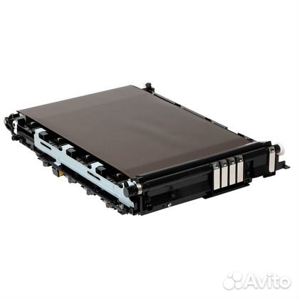
Продаётся Б/У ЗиП для Kyocera FS-C2026MFP,C2126MFP,C2026MFP+, C2126MFP+,C2526MFP,C2626MFP,C5150DN,C5250DN,P6021CDN,P6026CDN,M6526cdn,M6026cdn
302KV93040 | FK-590 Печь в сборе FK-590 3500,00 руб
302HN93013 | 2HN93010 | 2HN93011 | 2HN93012 | 2HN93013 | 302HN93010 | 302HN93011 | 302HN93012 | DV-560 DV560K Блок проявки DV-560K (чёрный цвет) 3500,00 руб
302HN93023 | 2HN93020 | 302HN93020 | 302HN93021 | 302HN93022 | DV-560Y Блок проявки DV-560Y (жёлтый цвет) 3500,00 руб
302HN93033 | 2HN93030 | 302HN93030 | 302HN93031 | 302HN93032 | DV-560C Блок проявки DV-560C (голубой цвет) 3500,00 руб
302HN93043 | 2HN93040 | 2HN93041 | 2HN93042 | 2HN93043 | 302HN93040 | 302HN93041 | 302HN93042 | DV-560M Блок проявки DV-560M (пурпурный цвет) 3500,00 руб
302KV93018 | 302KV93017 | 2KV93011 | 2KV93012 | 2KV93013 | 2KV93014 | 2KV93015 | 2KV93016 | 2KV93017 | 302KV93010 | 302KV93011 | 302KV93012 | 302KV93013 | 302KV93014 | 302KV93015 | 302KV93016 | DK-590 | T02KV00500 | 2KV93010 Драм-юнит DK-590 3500,00руб
302KV93070 | TR-590 Узел переноса изображения TR-590 5000,00 руб
Восстановление блоков проявок, замена девелопера.
Устранение ошибки 7401, 7402, 7403, 7404 в цветных машинах Kyocera.
2. Повреждения данных PWB EEPROM (U17)
2. Обратиться в сервис обслуживания
2. Повреждения данных PWB EEPROM (U17)
2. Обратиться в сервис обслуживания
2. Повреждение провода между платой PWB (YC30) и интерфесным разъемом устройства подачи, либо разъем подключен неправильно.
3. Неисправен кабель между PF основной PWB и подачей бумаги, либо разъем не вставлен. Плата PF неисправна.
4. Неисправность control PWB
2. Убедитесь, что разъем подключен, а кабель не поврежден. При необходимости — замените.
3. Убедитесь, что разъем подключен, а кабель не поврежден.Заменить печатную плату.
4. Заменить плату управления PWB.
2. Неисправность в системе управления факсом PWB
2. Заменить плату управления факсом PWB
2. Отсоединена батарея.
2. Визуально проверить и при необходимости исправить.
2. Неисправен привод основного двигателя.
3. Неисправен двигатель.
4. Неисправность control PWB
2. Проверьте плавность вращения роликов и шестерней. При необходимости смажьте. Убедитесь в отсутсвии разрывов передач.
3. Заменить.
4. Заменить.
2. Неисправность FFC между control PWB (YC6) и сканера WPB (YC103) или неправильная установка FCC.
3. Неисправность датчика исходного положения.
4. Неисправность кабеля между двигателем ISU и сканером PWB (YC104) или разъем вставлен неправильно.
2. Переставить FFC. Проверить на разрыв, при необходимости заменить.
3. Заменить датчик.
4. Вставьте разъем. Проверьте целостность кабеля.
2. Повреждения FFC между CCD PWB (YC1) и control PWB (YC8).
3. Неисправен кабель между CCD PWB (YC3) и LED приводом PWB (YC1) либо разъем не подключен.
4. Неисправен кабель между LED приводом PWB (YC2) и лампой экспонирования.
5. Лампа экспонирования вышла из строя.
6. Неисправен светодиодный привод.
2. Заменить блок сканера.
3. Убедитесь, что разъем подключен, а кабель не поврежден. При необходимости — замените.
4. Убедитесь, что разъем подключен, а кабель не поврежден. При необходимости — замените.
5. Заменить лампу.
6. Заменить привод.
2. Лампа экспонирования вышла из строя.
3. Неисправность CCD PWB
4. Неисправность control PWB
2. Заменить лампу.
3. Заменить CCD PWB
4. Заменить control PWB
2. Неисправность CCD PWB.
3. Неисправность control PWB
2. Заменить CCD PWB
3. Заменить control PWB
2. Неисправен блок лазерного сканера.
3. Неисправность control PWB
2. Заменить блок сканера.
3. Заменить control PWB
2. Неисправен блок лазерного сканера.
2. Заменить блок сканера.
2. Плохой контакт в местах подключения нагревателя термоблока.
3. Термисторы фьюзера установлены неправильно.
4 . Срабатывает термореле
5. Нагреватель фьюзера установлен неправильно
6. Выход из строя термо-элемента
2. Проверьте контакты.
3. Заменить блок закрепления
4. Заменить блок закрепления
5. Заменить блок закрепления
6. Заменить блок закрепления
2. Неисправен шлейф термистора
3. Термистор установлен некорректно
4. Срабатывает термореле
Заменить блок закрепления
2. Дефект соединения между источником питания PWB (YC103) и PWB высокого напряжения (YC201)
3. Неисправен источник питания PWB
4. Неисправность control PWB
2. Переподключите коннектор
3. Заменить источник питания
4. Заменить control PWB
2. Неисправен датчик отработки
3. Неисправность control PWB
2. Замените датчик.
3. Заменить control PWB
4. Очистите драм юнит (инструкция по очистке бункера отработанного тонера)
2. Неисправность панели управления
3. Неисправность control PWB
2. Замените панель.
3. Заменить control PWB
2. Неисправность платы расширения памяти (DIMM)
2. Замените плату расширения (DIMM)
2. Неисправность control PWB
2. Перезагрузите машину кратковременным выключением питания, если ошибка не исчезла, замените control PWB
Чем мы можем вам сегодня помочь?
Изменено: Чт, 12 Июл, 2018 на 3:35 PM
В машинах Kyocera P6021cdn, P6026cdn, M6026cdn/cidn, M6526cdn/cidn, FSC5150/5250/5350 и многих других довольно часто приходится сталкиваться с ошибкам C7401, C7402, C7403, C7404.
Описание этих ошибок в сервисной документации такое: «Developing unit non-installing error». Суть ошибок — машина не «видит» сигнала с датчика концентрации тонера в блоке проявки (7401 –Black, 7402 – Cyan, 7403 – Magenta, 7404 – Yellow).
Т.е. показания датчика выходят за допустимый диапазон, что может быть вызвано чрезмерно низкой концентрацией тонера в девелопере или недостаточным количеством девелопера в блоке проявки. Предлагаемый сервисной документацией способ устранения проблемы обычно заканчивается весьма дорогим пунктом — заменой блоков проявки целиком.
Частые причины появления проблемы – использование «не очень совместимого» тонера или использование машины не по своему назначению. Машины предназначены для офисной печати в нормальных условиях, и не очень хорошо справляются с печатью при высоком или низком заполнении тонером напечатанных страниц, а также в условиях высокой или низкой влажности воздуха.
Рекомендуемый нами метод лечения, опробованный на нескольких машинах:
- Для очистки совести проверить разъемы и провода на пути от датчиков концентрации тонера до платы.
- Проверить систему подачи тонера – часто ломаются шестерни шнеков подачи тонера, которые находятся в блоке ленты переноса.
- Опустить магнит в бункер отработки, чтобы выяснить имел ли место «вынос» девелопера в отработку.
- При отсутствии девелопера в бункере отработки вручную добавить и распределить тонер в блок проявки. Добавлять через входное отверстие блока проявки, распределять вращением валов блока проявки за шестерню. Обычно для вывода машины из состояния ошибки достаточно добавить 3-5 г тонера и вращать вручную шестерню блока проявки 2-3 минуты.
- При присутствии девелопера в бункере отработки сначала вручную добавить совместимый носитель в блок проявки, затем тонер. Добавлять через входное отверстие блока проявки, распределять вращением валов блока проявки за шестерню. Примерное количество носителя, которое нужно добавить, можно выяснить сравнением веса проблемного и «живого» блока проявки.
- После входа машины на готовность запустить из меню машины процедуру DEV-CLN (1 раз, чтобы не заклинить систему вывода отработки!) затем калибровку цвета. Это позволит машине довести концентрацию тонера до установленных значений.
Профилактика:
- Обновление прошивки. Kyocera иногда вносит в прошивки коррекции, связанные с алгоритмом подкачки тонера.
- Использование «нормального» тонера.
- Беседа с клиентом о том, что офисная машина предназначена для печати офисных документов, а не для оперативной полиграфии и т.п.
Была ли эта статья полезной?
Да
Нет
Отправить отзыв
К сожалению, мы не смогли помочь вам в разрешении проблемы. Ваш отзыв позволит нам улучшить эту статью.