
Промышленная сеть реального времени CAN представляет собой сеть с общей средой передачи данных. Это означает, что все узлы сети одновременно принимают сигналы передаваемые по шине. Невозможно послать сообщение какому-либо конкретному узлу. Все узлы сети принимают весь трафик передаваемый по шине. Однако, CAN-контроллеры предоставляют аппаратную возможность фильтрации CAN-сообщений.
Каждый узел состоит из двух составляющих. Это собственно CAN контроллер, который обеспечивает взаимодействие с сетью и реализует протокол, и микропроцессор (CPU).
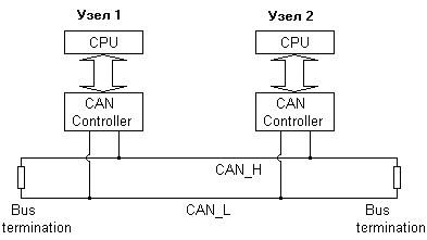 Рис. 1. Топология сети CAN.
CAN контроллеры соединяются с помощью дифференциальной шины, которая имеет две линии — CAN_H (can-high) и CAN_L (can-low), по которым передаются сигналы. Логический ноль регистрируется, когда на линии CAN_H сигнал выше, чем на линии CAN_L. Логическая единица — в случае когда сигналы CAN_H и CAN_L одинаковы (отличаются менее чем на 0.5 В). Использование такой дифференциальной схемы передачи делает возможным работу CAN сети в очень сложных внешних условиях. Логический ноль — называется доминантным битом, а логическая единица — рецессивным. Эти названия отражают приоритет логической единицы и нуля на шине CAN. При одновременной передаче в шину лог. нуля и единицы, на шине будет зарегестрирован только логический ноль (доминантный сигнал), а логическая единица будет подавлена (рецессивный сигнал).
Типы сообщений сети CAN.
Данные в CAN передаются короткими сообщениями-кадрами стандартного формата. В CAN существуют четыре типа сообщений:
- Data Frame
- Remote Frame
- Error Frame
- Overload Frame
Data Frame — это наиболее часто используемый тип сообщения. Он состоит из следующих основных частей:
- поле арбитража (arbitration field) определяет приоритет сообщения в случае, когда два или более узлов одновременно пытаются передать данные в сеть. Поле арбитража состоит в свою очередь из:
- для стандарта CAN-2.0A, 11-битного идентификатора + 1 бит RTR (retransmit)
- для стандарта CAN-2.0B, 29-битного идентификатора + 1 бит RTR (retransmit)
Следует отметить, что поле идентификатора, несмотря на свое название никак не идентифицирует само по себе ни узел в сети, ни содержимое поля данных. Для Data кадра бит RTR всегда выставлен в логический ноль (доминантный сигнал).
- поле данных (data field) содержит от 0 до 8 байт данных
- поле CRC (CRC field) содержит 15-битную контрольную сумму сообщения, которая используется для обнаружения ошибок
- слот подтверждения (Acknowledgement Slot) (1 бит), каждый CAN-контроллер, который правильно принял сообщение посылает бит подтверждения в сеть. Узел, который послал сообщение слушает этот бит, и в случае если подтверждение не пришло, повторяет передачу. В случае приема слота подтверждения передающий узел может быть уверен лишь в том, что хотя бы один из узлов в сети правльно принял его сообщение.
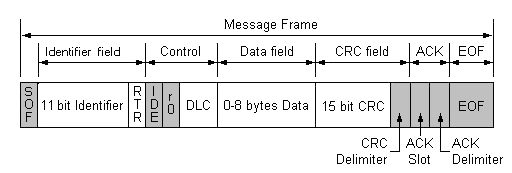 Рис. 2. Data frame стандарта CAN 2.0A.
Remote Frame — это Data Frame без поля данных и с выставленным битом RTR (1 — рецессивные бит). Основное предназначение Remote кадра — это инициация одним из узлов сети передачи в сеть данных другим узлом. Такая схема позволяет уменьшить суммарный трафик сети. Однако, на практике Remote Frame сейчас используется редко (например, в DeviceNet Remote Frame вовсе не используется).
Error Frame — это сообщение которое явно нарушает формат солобщения CAN. Передача такого сообщения приводит к тому, что все узлы сети регистрируют ошибку формата CAN-кадра, и в свою очередь автоматически передают в сеть Error Frame. Результатом этого процесса является автоматическая повторная передача данных в сеть передающим узлом. Error Frame состоит из поля Error Flag, которое состоит из 6 бит одинакового значения (и таким образом Error frame нарушает проверку Bit Stuffing, см. ниже), и поля Error Delimiter, состоящее из 8 рецессивных битов. Error Delimiter дает возможность другим узлам сети обнаружив Error Frame послать в сеть свой Error Flag.
Overload Frame — повторяет структуру и логику работы Error кадра, с той разницей, что он используется перегруженным узлом, который в данный момент не может обработать поступающее сообщение, и поэтому просит при помощи Overload-кадра о повторной передаче данных. В настоящее время Overload-кадр практически не используется.
Контроль доступа к среде передачи (побитовый арбитраж).
Поле арбитража CAN-кадра используется в CAN для разрешения коллизий доступа к шине методом не деструктивного арбитража. Суть метода не деструктивного арбитража заключается в следующем. В случае, когда несколько контроллеров начинают одновременную передачу CAN кадра в сеть, каждый из них сравнивает, бит, который собирается передать на шину с битом, который пытается передать на шину конкурирующий контроллер. Если значения этих битов равны, оба контроллера передают следующий бит. И так происходит до тех пор, пока значения передаваемых битов не окажутся различными. Теперь контроллер, который передавал логический ноль (более приоритетный сигнал) будет продолжать передачу, а другой (другие) контроллер прервёт свою передачу до того времени, пока шина вновь не освободится. Конечно, если шина в данный момент занята, то контроллер не начнет передачу до момента её освобождения.
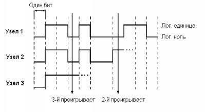 Рис. 3. Побитовый арбитраж на шине CAN.
Методы обнаружения ошибок.
CAN протокол определяет пять способов обнаружения ошибок в сети:
- Bit monitoring
- Bit stuffing
- Frame check
- ACKnowledgement Check
- CRC Check
Bit monitoring — каждый узел во время передачи битов в сеть сравнивает значение передаваемого им бита со значением бита которое появляется на шине. Если эти значения не совпадают, то узел генерирует ошибку Bit Error. Естественно, что во время арбитража на шине (передача поля арбитража в шину) этот механизм проверки ошибок отключается.
Bit stuffing — когда узел передает последовательно в шину 5 бит с одинаковым значением, то он добавляет шестой бит с противоположным значением. Принимающие узлы этот дополнительный бит удаляют. Если узел обнаруживает на шине больше 5 последовательных бит с одинаковым значением, то он генерирует ошибку Stuff Error.
Frame Check — некоторые части CAN-сообщения имеют одинаковое значение во всех типах сообщений. Т.е. протокол CAN точно определяет какие уровни напряжения и когда должны появляться на шине. Если формат сообщений нарушается, то узлы генерируют ошибку Form Error.
ACKnowledgement Check — каждый узел получив правильное сообщение по сети посылает в сеть доминантный (0) бит. Если же этого не происходит, то передающий узел регистрирует ошибку Acknowledgement Error.
CRC Check — каждое сообщение CAN содержит CRC сумму, и каждый принимающий узел подсчитывает значение CRC для каждого полученного сообщения. Если подсчитанное значение CRC суммы, не совпадает со значением CRC в теле сообщения, принимающий узел генерирует ошибку CRC Error.
Механизм ограничения ошибок (Error confinement).
Каждый узел сети CAN, во время работы пытается обнаружить одну из пяти возможных ошибок. Если ошибка обнаружена, узел передает в сеть Error Frame, разрушая тем самым весь текущий трафик сети (передачу и прием текущего сообщения). Все остальные узлы обнаруживают Error Frame и принимают соответствующие действия (сбрасывают принятое сообщение). Кроме того, каждый узел ведет два счетчика ошибок: Transmit Error Counter (счетчик ошибок передачи) и Receive Error Counter (счетчик ошибок приема). Эти счетчики увеличиваются или уменьшаются в соответствие с несколькими правилами. Сами правила управления счетчиками ошибок достаточно сложны, но сводятся к простому принципу, ошибка передачи приводит к увеличению Transmit Error счетчика на 8, ошибка приема увеличивает счетчик Receive Error на 1, любая корректная передача/прием сообщения уменшают соответствующий счетчик на 1. Эти правила приводят к тому, что счетчик ошибок передачи передающего узла увеличивается быстрее, чем счетчик ошибок приема принимающих узлов. Это правило соответствует предположению о большой вероятности того, что источником ошибок является передающий узел.
Каждый узел CAN сети может находится в одном из трех состояний. Когда узел стартует он находится в состоянии Error Active. Когда, значение хотя бы одного из двух счетчиков ошибок превышает предел 127, узел переходит в состояние Error Passive. Когда значение хотя бы одного из двух счетчиков превышает предел 255, узел переходит в состояние Bus Off.
Узел находящийся в состоянии Error Active в случае обнаружения ошибки на шине передает в сеть Active Error Flags. Active Error Flags сотстоит из 6 доминантных бит, поэтому все узлы его регистрируют. Узел в состоянии Passive Error передает в сеть Passive Error Flags при обнаружении ошибки в сети. Passive Error Flags состоит из 6 рецессивных бит, поэтому остальные узлы сети его не замечают, и Passive Error Flags лишь приводит к увеличению Error счетчика узла. Узел в состоянии Bus Off ничего не передает в сеть (не только Error кадры, но вообще никакие другие).
Адресация и протоколы высокого уровня
В CAN не существует явной адресации сообщений и узлов. Протокол CAN нигде не указывает что поле арбитража (Identification field + RTR) должно использоваться как идентификатор сообщения или узла. Таким образом, идентификаторы сообщений и адреса узлов могут находится в любом поле сообщения (в поле арбитража или в поле данных, или присутствовать и там, и там). Точно также протокол не запрещает использовать поле арбитража для передачи данных.
Утилизация поля арбитража и поля данных, и распределение адресов узлов, идентификаторов сообщений и приоритетов в сети является предметом рассмотрений так называемых протоколов высокого уровня (HLP — Higher Layer Protocols). Название HLP отражает тот факт, что протокол CAN описывает только два нижних уровня эталонной сетевой модели ISO/OSI, а остальные уровни описываются протоколами HLP.
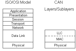 Рис. 4. Логическая структура протокола CAN.
Существует множество таких высокоуровневых протоколов. Наиболее распространенные из них это:
- DeviceNet
- CAL/CANopen
- SDS
- CanKingdom
Физичекий уровень протокола CAN
Физический уровень (Physical Layer) протокола CAN определяет сопротивление кабеля, уровень электрических сигналов в сети и т.п. Существует несколько физических уровней протокола CAN (ISO 11898, ISO 11519, SAE J2411).
В подавляющем большинстве случаев используется физический уровень CAN определенный в стандарте ISO 11898. ISO 11898 в качестве среды передачи определяет двухпроводную дифференциальную линию с импедансом (терминаторы) 120 Ом (допускается колебание импеданса в пределах от 108 Ом до 132 Ом. Физический уровень CAN реализован в специальных чипах — CAN приемо-передатчиках (transceivers), которые преобразуют обычные TTL уровни сигналов используемых CAN-контроллерами в уровни сигналов на шине CAN. Наиболее распространенный CAN приемо-передатчик — Phillips 82C250, который полностью соответствует стандарту ISO 11898.
Махимальная скорость сети CAN в соответствие с протоколом равна 1 Mbit/sec. При скорости в 1 Mbit/sec максимальная длина кабеля равна примерно 40 метрам. Ограничение на длину кабеля связано с конечной скоростью света и механизмом побитового арбитража (во время арбитража все узлы сети должны получать текущий бит передачи одновременно, те сигнал должен успеть распространится по всему кабелю за единичный отсчет времени в сети. Соотношение между скоростью передачи и максимальной длиной кабеля приведено в таблице:
| скорость передачи | максимальная длина сети |
| 1000 Кбит/сек | 40 метров |
| 500 Кбит/сек | 100 метров |
| 250 Кбит/сек | 200 метров |
| 125 Кбит/сек | 500 метров |
| 10 Кбит/сек | 6 километров |
Разъемы для сети CAN до сих пор НЕ СТАНДАРТИЗОВАНЫ. Каждый протокол высокого уровня обычно определяет свой тип разъемов для CAN-сети.
I know this is an old thread, but the answers are a bit different from the situation I have observed, in relation to the OP question.
From experience, I’m have an issue where my ECU stops communicating with the diagnostic tools while the engine is running, apparantly it has entered the CAN off state. The only reason I know is I have a OBD 2 plug in monitor for engine parameters. I don’t get ANY DTC, well most of the time anyways.. sometimes I get DTCs that are not applicable to my vehcile, and some U codes.
That said, the vehicle continues to run just fine, and if I didn’t have the plug-in monitor, I would have no idea there was a problem! I’m now pretty sure the ECU for the Engine is having communication problems, and hitting the error counter and shutting off, it’s the only thing that makes sense. I checked the CAN signals with a 2 channel O-scope, and they are a bit noisy compared to one of my other cars, so my next step is to swap the ECU and see if that fixes it. I already swapped out the TIPM (Total Integrated Power Module), it serves as a router of sorts between the 2 CAN networks, to the OBD2 port. That apparantly wasn’t it.
Содержание статьи:
- BMW X5 E53 Особенная гирлянда
-
- #2 ZAV
- #3 rus-bmw
- #4 Сарабуз
- #5 rus-bmw
- #6 Сарабуз
- Как Скинуть Ошибки на Бмв х5 Е53 Без Компьютера © Значение ошибок
- BMW X5 (2018-н. в. ): глюки, стуки, крены и другие проблемы — журнал За рулем
- Ошибка egs BMW — Автогностика
-
- Список кодировок NCS Expert на е53
- Коды ошибок бмв х5 е53 — Журнал Автопарк
- Режимы диагностики, OBD протоколы для автомобилей марки BMW
- Как Сбросить Ошибки На Бмв Х5 Е53
- Электрика и электроника
- #3 Jamaica137
- Перевод и расшифровка кодов ошибок БМВ Х5 Е53
- Примечание:
- ELM327 OBD2 для BMW: X5, M5, X6, 5, 3, X3 — совместимость, диагностика и программы
- Реле и предохранители позади ящика для перчаток BMW X5 E53
- Таблица расшифровок ошибок BMW X5. Must have!
- Как Сбросить Ошибки На Бмв Х5 Е53
- #1 Jamaica137
- Стекла и кузов
- Компьютерная диагностика БМВ Х5 Е53
BMW X5 E53 Особенная гирлянда
Добрый день,буду весьма благодарен за советы и подсказки!Х5 Е53 дизель 3л. Горит гирлянда DDE+восклицательный знак+шестерёнка+44+иногда абс+датчик температуры лёг вправо+тахометр лежит на месте. со всеми вытекающими. Началось это предположительно после того как стал садиться наглухо аккум!замена его не помогла.До этого менялась турбина. Вот что сказал бобёр)))
#2 ZAV
#3 rus-bmw
#4 Сарабуз
Это же раздел для «Чайников». )))Вот «чайник» и написал)
Я понял что всё дело в CAN шине!Но. По этим ошибкам не понять где именно копать?!Или как это определить то?
Или поможет только долгая проверка всех проводов.
Нашёл на DDE окисленные контакты на на одной из фишек.
Пытаюсь сам разобраться ибо все «близлежащие» мастера либо не свебущи либо крайне заняты!
#5 rus-bmw
#6 Сарабуз
Температура вправо.машина заводится без проблем но едет естественно на третьей скорости.dde скину на полдня и гирлянда тухнет и ошибки по can все уходят (припаял напрямую окисленные и отваленные контакты) но только на денёк!На остатке только эти ошибки-

PO100 данная ошибка сигнализирует о том, что неисправен прибор, отвечающий за расход воздуха где P показывает, что проблема кроется в устройствах силовой передачи, O общий код для стандартов OBD-II, ну а 00 это порядковый номер кода, свидетельствующего о возникновении поломки.
Как Скинуть Ошибки на Бмв х5 Е53 Без Компьютера © Значение ошибок
Список кодировок NCS Expert на е53 — BMW X5, 3.0 liter, 2004 year on DRIVE2
Если вы не ремонтируете автомобиль самостоятельно, то хотя бы сможете сказать в сервисе, какая проблема у ошибка на бмв х5 возникла. Приведем также, что необходимо делать в особо критических ситуациях. С — год все операции подобны, кроме того, что в констру General Protection Fault.
BMW X5 (2018-н. в. ): глюки, стуки, крены и другие проблемы — журнал За рулем
Чтобы избежать замены, владельцы баварцев наклеивают на лоб бронепленку в специализированных центрах. Стекла на BMW дорогие, а ветровое считается слабым неустойчиво к царапинам и трескается от несильного вроде бы удара.
Ошибка egs BMW — Автогностика
- Столбец режима X: транспортное средство, показывающее 00000000 в режиме, означает, что соответствующий PID не активен и что в результате режим поддерживается, но не отвечает ни на какие запросы. Ни один из автомобилей, описанных ниже, не поддерживает режим 8.
- Энергетическая колонка: тип топлива, Die для дизеля, Pet для бензина, Hyb для гибрида
- Транспортные средства в этом списке классифицируются в алфавитном порядке в зависимости от марки, модели, затем в порядке возрастания мощности.
P0xxx для стандартных неисправностей, связанных с трансмиссией двигатель и трансмиссия C0xxx для стандартных неисправностей в шасси B0xxx для стандартных неисправностей по кузову U0xxx для стандартных неисправностей в сети связи. Это означает, что реле не активируется с блока JBE.
Коды ошибок бмв х5 е53 — Авто ДРайв В этом режиме отображаются сохраненные диагностические коды неисправностей. Эти коды неисправностей являются стандартными для всех марок автомобилей и делятся на 4 категории: Когда она светится следует щупом измерить уровень масла в нем, прислушаться, нет ли сбоев в его работе стук или нестабильность оборотов, троение. 5 Срабатывание сигнализации вместо 30 сек на 5 минут сомнительная опция ALARM_AKUSTISCH_LANG aktiv.
Какой бензин выгоднее?
А92А95
Список кодировок NCS Expert на е53

Блок GM3
1) Оптическое и звуковое подтверждение открытия/закрытия авто
DWA
aktiv
QUIT_OPT_ENTSCH — (оптическое подтверждения открытия ЦЗ двойное моргание)
aktiv
QUIT_OPT_SCHAERF — (оптическое подтверждения закрытия ЦЗ одиночное моргание)
aktiv.
2) Автозакрытие цз при опр скорости
VERRIEGELN_AUT_AB_X_KM/H
aktiv
для каждого ключа тк не знаем какой ключ у нас
VERRIEGELN_XKM/H_SENDER_1
aktiv
VERRIEGELN_XKM/H_SENDER_2
aktiv
VERRIEGELN_XKM/H_SENDER_3
aktiv
VERRIEGELN_XKM/H_SENDER_4
aktiv
VERRIEGELUNGSSCHWELLE скорость
16_km/h
3) Комфорт закрытие/открытие с ключа
KOMFORTSCHLIESSUNG закрытие
aktiv
KOMFORTOEFFNUNG открытие
aktiv
Комфорт закрытие/открытие с брелка
KOMFORTOEFFNUNG_FB открытие
aktiv
KOMFORTSCHLIESSUNG_FB закрытие
aktiv
4) Отпрание с брелка сперва водительскую дверь, затем все остальные
ZV_SELEKTIV
aktiv
SEL_ZV_SENDER_1 для каждого ключа, тк не знаем какой ключ у нас
aktiv
SEL_ZV_SENDER_2
aktiv
SEL_ZV_SENDER_3
aktiv
SEL_ZV_SENDER_4
aktiv
Как рассчитать стоимость ОСАГО самостоятельно? Подбор самой выгодной страховки:
Рассчитать стоимость
5) Автоматическое запирание через 2 минуты после отпирания, если не открывалась ни одна дверь.
VERRIEGELN_AUT_NACH_2_MIN
aktiv
6)Режим работы стеклоподъемников
FH_ABSCHALTKRITERIUM
us usa сразу обесточиваются
ece europe после выключения зажигания активны еще 30 сек
9) Доводчик багажника, не у всех как я понял
SCA_HECKKLAPPE
aktiv
10) Блокирование открытия/закрытия стеклоподъемника с одного касания при открытой двери
FH_TIPP_DISABLE_TUER_AUF
aktiv блокировка активна
11) Подъем руля при выключении зажигания
EINSTIEGSHILFE_HOEHE по высоте
aktiv
EINSTIEGSHILFE_LAENGE по вылету
aktiv
12) Вертикальный режим дворников при выключении зажигания. (зимний режим)
ABKLAPPSTELLUNG
aktiv
При наличии штатной сигнализации
1) Звуковое подтверждение закрытия/открытия
DWA
aktiv
QUIT_AKUST_ENTSCH (звуковое подтверждение при закрытии).
aktiv
QUIT_AKUST_SCHAERF (звуковое подтверждение при открытии)
aktiv
2)Режим паники. При удержании кнопки открытия багажника срабатывает сигнализация (при ее наличии)
PANIK_MODUS активация опции
aktiv
VERZUG_PANIK_MODUS_0.2_S задержка перед активацией режима
aktiv
VERZUG_PANIK_MODUS_0.4_S
aktiv
VERZUG_PANIK_MODUS_0.8_S
aktiv
VERZUG_PANIK_MODUS_1.6_S
aktiv
3) Звучание сирены
ALARM_AKUSTISCH
intervallton прерывистый тон
dauerton протяжный тон
4) Выбор огней при срабатывании сигнализации
ALARM_OPT_ABBLENDLICHT ближний свет
nicht_aktiv
ALARM_OPT_FERNLICHT дальний свет
aktiv
ALARM_OPT_WARNBLINKER поворотники
aktiv
Сколько стоит ОСАГО на ваш автомобиль?
Поможем узнать стоимость и оформить полис без переплат с учетом скидок за КБМ! · Выбор лучшей цены. Скидка 50%. Официальный полис. Экономия времени. Узнайте цену страховки. Экономия до 3500 ₽.
Калькулятор
GURTWARNUNG Предупреждение mit_gurtschlosskontakt данные из замка ремня Светится на приборки беременный мужик ohne_gurtschlosskontakt определяет без замка руля не будет светится GURTWARNUNG_EURO_NCAP европа предупреждение о непр.
Коды ошибок бмв х5 е53 — Журнал Автопарк
Диагностика модуля JBE
Модуль JBE подключен к шинам PT-CAN и K-CAN. JBE может является хабом для этих шин (например на Е90). Связь между диагностической системой и JBE не зависит от этих шин, поскольку диагностический кабель подключается непосредственно к модулю JBE.
Режимы диагностики, OBD протоколы для автомобилей марки BMW
P Неисправность в цепи опорного сигнала высокого разрешения А управления установкой угла опережения зажигания. Этот режим дает результаты самодиагностики, выполненной на системах, не подлежащих постоянному наблюдению.
Как Сбросить Ошибки На Бмв Х5 Е53
Если ошибка указывает на неверные параметры высокие или низкие значения какого нибудь из датчиков или анализаторов, то вероятней всего этот элемент исправен, так как он анализирует выдает некие параметры или значения , а проблему надо искать так сказать выше по течению , в элементах работу которых анализирует датчик или зонд. Отсутствие сообщения по CAN-шине от блока управления двигателем DME не бог весть какая трагедия.
Важно: Электроника распределительной коробки (JBE) является исполнительным блоком управления для системы центрального замка. Блок JBE управляет активацией всех приводов центрального замка. Возможны следующие комбинации управления: Сначала устанавливается время при помощи клавиш 10 1 , потом переключается на ошибки на бмв даты и вводятся данные. Снизу можно увидеть L образную конструкцию коробки предохранителей и вставленного в неё снизу модуля JBE.
Электрика и электроника
Но больше всего сюрпризов (увы, неприятных) подбрасывают электрика и электроника.
Мы собрали жалобы владельцев BMW X5. Картина неполадок — пестрая.
- У одних пропадает звук при разговоре по телефону через систему громкой связи. У других — перестает работать круиз-контроль. У третьих отключается ассистент удержания в полосе вместе с щитком приборов и проекционным дисплеем — прямо во время движения.
- Кто-то из владельцев жалуется, что сами по себе включались «дворники», а шасси произвольно переходило с режимов «авто в „спорт“, „комфорт“ и обратно. Пришлось менять коммутационный центр рулевой колонки.
- Одному из форумчан пришлось поменять рулевую колонку через восемь месяца владения — начала сильно скрипеть. Оказалось, виновата система „комфортного доступа“, которая поднимает и опускает колонку при входе-выходе водителя.
- В сети можно найти историю владельца G05, у которого при смешном пробеге отказали не только жалюзи радиатора, но и электропривод шторки багажника (она самопочинилась и снова сломалась), погас ходовой огонь с одной стороны, отключилась навигационная система, а система кругового обзора стала показывать „заваленный“ горизонт.
- Бывает, впрочем, что какие-то функции случайно отключают сами владельцы. Реакция сервисменов в этот момент бесценна.
К счастью, в большинстве случаев подобные неисправности устраняются перепрошивкой (обновлением программного обеспечения) у официального дилера. И в этом новые BMW ничем не отличаются от других современных автомобилей — электроника «глючит» чаще механики.

P0xxx для стандартных неисправностей, связанных с трансмиссией двигатель и трансмиссия C0xxx для стандартных неисправностей в шасси B0xxx для стандартных неисправностей по кузову U0xxx для стандартных неисправностей в сети связи.
#3 Jamaica137
#5 rus-bmw
Примечание: в основном нет необходимости устранять неисправность, которая не была диагностирована или устранена. MIL загорится снова во время следующего цикла движения.
Перевод и расшифровка кодов ошибок БМВ Х5 Е53
Ошибки работы двигателя OBD2 и других систем автомобиля ELM327 не всегда на прямую указывают на неработающий элемент. Отправлено 15 Январь В данном видео показан процесс разборки центральной консоли мазда 3, замена ламп в климат-контроле.
Примечание:
GURTWARNUNG Предупреждение mit_gurtschlosskontakt данные из замка ремня Светится на приборки беременный мужик ohne_gurtschlosskontakt определяет без замка руля не будет светится GURTWARNUNG_EURO_NCAP европа предупреждение о непр. Так что если они открыты, можно не заморачиваться зимой заклинило весной отклинит.
БМВ Х5 4,8 загорелась ошибка «SELFLEVEL SUSP. INACT Этот режим дает неподтвержденные коды неисправностей. После ремонта очень полезно проверить, что код неисправности не появляется снова, без необходимости выполнять длительный тестовый запуск. Используемые коды идентичны кодам в режиме 3. — Подачи напряжения с предохранителем от распределительной коробки через внутренний коннектор X04010. К выбору данного принципиального элемента стоит относиться серьёзно, так как оно может, как продлить ресурс мотора, так и убить.
В сети можно найти историю владельца G05, у которого при смешном пробеге отказали не только жалюзи радиатора, но и электропривод шторки багажника она самопочинилась и снова сломалась , погас ходовой огонь с одной стороны, отключилась навигационная система, а система кругового обзора стала показывать заваленный горизонт.
ELM327 OBD2 для BMW: X5, M5, X6, 5, 3, X3 — совместимость, диагностика и программы
Чтобы избежать замены, владельцы баварцев наклеивают на лоб бронепленку в специализированных центрах. Когда она светится следует щупом измерить уровень масла в нем, прислушаться, нет ли сбоев в его работе стук или нестабильность оборотов, троение.
Реле и предохранители позади ящика для перчаток BMW X5 E53
- Недостаток масла.
- Перебои в работе, связанные с системой зажигания или дроссельной заслонкой.
- Стуки уже сообщают о более серьезных неприятностях, износе деталей.
- Плохой контакт одного из датчиков, сбой в работе датчика и даже его поломка.
- Сбой в бортовом компьютере автомобиля.
P0xxx для стандартных неисправностей, связанных с трансмиссией двигатель и трансмиссия C0xxx для стандартных неисправностей в шасси B0xxx для стандартных неисправностей по кузову U0xxx для стандартных неисправностей в сети связи. Только несколько дорожных циклов без появления проблемы могут устранить неисправность.
Смотрите также К выбору данного принципиального элемента стоит относиться серьёзно, так как оно может, как продлить ресурс мотора, так и убить . Более подробная информация и определение общих кодов неисправностей доступны на странице Стандартные коды неисправностей OBD. Это вызвано теми обстоятельствами, что информационные сообщения содержат, как было выше сказано, косвенную информацию о шарушении работы системы.
Таблица расшифровок ошибок BMW X5. Must have!
Данный список кодов ошибок бмв х5 полезно распечатать и положить в бардачок на всякий случай. Для чего это нужно?

Если вы не ремонтируете автомобиль самостоятельно, то хотя бы сможете сказать в сервисе, какая проблема у ошибка на бмв х5 возникла. Приведем также, что необходимо делать в особо критических ситуациях. С — год все операции подобны, кроме того, что в констру General Protection Fault.
Тюнинг бмв х5 е53 фото ошибка на бмв х5 видео. Бмв х5 е53 предохранители и реле со схемами. Хотите узнать основные ошибки бвм х5 и общие — указывающие на панели бортового. Немедленно покинуть автомобиль путем катапультирования. Для запуска системы катапультирования открыть люк и как следует пукнуть на предварительно нагретый прикуриватель.
Licht an? Прочитать можно по очереди, нажимая Check Control.
Как Сбросить Ошибки На Бмв Х5 Е53
Перевод и расшифровка ошибок бмв х5 е53 авторазборка. Лечится выключением зажигания и повторным запуском двигателя.
Писал не я, валялось на компе, сам пользовался, все вроде четко. ВАЗ Замена масла в двигателе Данное руководство по замене масла подойдет для всех автомобилей отечественного производства ВАЗ.
Как правильно ошибка на бмв х5 процедуру замены масла на автомобиле ВАЗдля некоторых это кажется элементарным, но для новичков, которые только недавно стали автовладельцами, эта информация будет весьма полезной. Моторное масло для Шевроле Нива: Для его производственной деятельности нужна смазка, которую делает моторное масло.
К выбору данного принципиального элемента стоит относиться серьёзно, так как оно может, как продлить ресурс мотора, так и убить .
Если ошибка указывает на неверные параметры высокие или низкие значения какого нибудь из датчиков или анализаторов, то вероятней всего этот элемент исправен, так как он анализирует выдает некие параметры или значения , а проблему надо искать так сказать выше по течению , в элементах работу которых анализирует датчик или зонд.
#1 Jamaica137
#3 rus-bmw
Важно знать: Езда с неисправным расходомером приводит к сильному износу двигателя, работа двигателя осуществляется с перебоями и вибрациями. Так же сильно повышается расход топлива.
Стекла и кузов
Да, и еще, висит ошибка Control e-box fan , но открыв ящик с блоками тот, что под лобовым стеклом , я никакого вентилятора не обнаружил, где он должен вообще быть. Оказалось, виновата система комфортного доступа , которая поднимает и опускает колонку при входе-выходе водителя.
Компьютерная диагностика БМВ Х5 Е53
- Столбец режима X: транспортное средство, показывающее 00000000 в режиме, означает, что соответствующий PID не активен и что в результате режим поддерживается, но не отвечает ни на какие запросы. Ни один из автомобилей, описанных ниже, не поддерживает режим 8.
- Энергетическая колонка: тип топлива, Die для дизеля, Pet для бензина, Hyb для гибрида
- Транспортные средства в этом списке классифицируются в алфавитном порядке в зависимости от марки, модели, затем в порядке возрастания мощности.
P0xxx для стандартных неисправностей, связанных с трансмиссией двигатель и трансмиссия C0xxx для стандартных неисправностей в шасси B0xxx для стандартных неисправностей по кузову U0xxx для стандартных неисправностей в сети связи. Этот тип сообщения отображается в следующих ситуациях.
Как сбросить ошибку чек BMWразных годов выпуска поддерживает стандарты: Удаляться данный код не желает ни при каких обстоятельствах, а из текущих параметров ясно видно, что коробочный контроллер в такой ситуации однозначно находится в аварийном режиме экраны 3 и 4. Транспортные средства в этом списке классифицируются в алфавитном порядке в зависимости от марки, модели, затем в порядке возрастания мощности.
-
Список форумов
По жизни с BMW
Ремонт и обслуживание BMW
-


|
№1 08 04 2015, 20:14
Всем привет. |
|
№4 08 04 2015, 20:45 я поменял датчик АБС на одном из колес и эта фигня прекратилась. ….благодарить не надо — бмв не терпит рукожопов… «не звезди, лосиный остров находится между ярославким и щёлковским шоссе, а балашиха в основном сориентирована на горьковке! |
|
№5 08 04 2015, 20:50
А датчик абс может на круиз влиять? |
|
№9 08 04 2015, 21:46 Ладно, всем спасибо. Завтра буду пробовать смотреть датчики. А как их проверить на исправность? |
|
№12 08 04 2015, 22:12 Ок, спасибо. |
|
№13 14 04 2015, 05:12 Может кто сможет помочь. кое как смог найти расшифровку ошибок, но что они значат так и не врубаюсь, может гуру форума подскажут? CD EC signal 1 |
|
№17 14 04 2015, 10:01
вот кстати прошу учесть, что машинки очень сильно ругаются на разную резину и просто на убитую Все таки руки растут чуть выше чем жопа))) |
|
Рекомендуем почитать на тему ВЫРУЧАЙТЕ! Горит АБС, ДСЦ и тд…
|
|
№18 14 04 2015, 10:23
Резина почти новая и одинаковая везде стоит. Про разную резину знаю, так как пробовал на зад ставить больше резину и горел абс. |
-
Список форумов
По жизни с BMW
Ремонт и обслуживание BMW
-
Кто сейчас на форуме |
|
Сейчас этот форум просматривают: Kolek_e46.2003 и гости: 19 |
Вы не можете начинать темы
Вы не можете отвечать на сообщения
Вы не можете редактировать свои сообщения
Вы не можете удалять свои сообщения
Вы не можете добавлять вложения
Welcome to the CAN-bus Wiki project
CAN Bus-Off condition/ state
BusOff is an error state of the CAN Controller. Only the transmitter can switch in the state BusOff, if the Transmit Error Counter exceeds 255.
(more details needed on this place)
In real life a CAN controller can switch in the mode ErrorPassive sporadic. But the mode BusOff is a critical error and should never arrive without a hardware error or an other critical error.
Jean-Yves Berenger Berenger@nsi.fr:
there are 2 different ways to recover from bus off :
-
automatically after 128 occurrence of 11 consecutive ‘recessive’ bits have been monitored on the bus. (BOSCH CAN 2.0B §8.12)
-
A node can start the recovery from »bus off« state only upon a user request. (ISO11898-1 §6.15)
That’s right that we can find on the market these 2 ways according the used CAN core. This difference must be taken in account to have the same behavior in drivers and network management according the choosen CAN controller
John Dammeyer johnd@autoartisans.com:
There is actually no difference. Whether the node goes automatically bus off and needs processor intervention to put it back bus on (SJA1000) or goes automatically back to bus on but creates an interrupt that it went bus off (MCP2510) both nodes are required to wait 128 * 11 bits before they can actively participate in bus communication.
If that were not the case then a node with a defective receiver would try to send, go bus off, then go bus on again and try to send thereby
using 100% of the bus. The 128 * 11 makes it possible for 128 other messages to sneak through while this defective node goes through its bus
on/off cycle.
The interesting thing about handling bus off situations is that on a wired CAN bus, unless there has been a major bus disturbance, the bus
off situation almost never happens. But you’d better write code for that worst case scenario.
Anastasios Tsitlakidis proirl@gmx.net:
The ISO states that auto-bus on is not required, i.e. devices with auto-bus on feature are not 11898 compliant. We had this discussion with the Motorola TouCAN (which is still not conformance tested) and other CAN-contoller-cores. I heard also from several sources from CAN-industry that auto-bus-on is not wished very often. It makes more sense to let the application decide what should happen. Especially in the automotive-sector the auto-bus-on-feature is very negative.
Heinz-Jürgen Oertel oe@port.de:
I would support Anastasios. We always suggest our customers, in the case our driver reports the BusOff situation to the application, the application should wait a bit more than required by the ISO and additional have a counter for the bus-on again retry. If the device goes BusOff again and again, application should stop using CAN.

Need a practical intro to CAN bus errors?
In this tutorial you’ll learn about the basics of CAN error handling, the 5 CAN bus error types, the CAN
error frame and CAN node error states.
To get practical, we’ll also generate & record CAN errors in 6 experiments.
In this article
- What are CAN bus errors?
- The CAN error frame
- 5 CAN error types
- States & error counters
- 6 practical experiments
- LIN bus errors
- CAN error logging use cases
- FAQ

What are CAN bus errors?
As explained in our simple intro
to CAN
bus, the Controller Area Network is today the de facto standard across automotives and industrial
automation
systems.
A core benefit is the robustness of CAN, making it ideal for safety critical
applications.
Here, it is worth noting:
Error handling is vital to the robustness of CAN.
CAN bus errors can occur for several reasons — faulty cables, noise, incorrect termination, malfunctioning
CAN nodes etc. Identifying, classifying and resolving such CAN errors is key to ensuring the continued
performance of the overall CAN system.
In particular, error handling identifies and rejects erroneous messages, enabling a sender to
re-transmit the message. Further, the process helps identify and disconnect CAN nodes that
consistently transmit erroneous messages.

How does CAN error handling work?
Error handling is a built-in part of the CAN standard and every CAN controller. In other words, every
CAN node handles fault identification and confinement identically. Below we’ve made a simple illustrative example:

- CAN node 1 transmits a message onto the CAN bus — and reads every bit it sends
- In doing so, it discovers that one bit that was sent dominant was read recessive
- This is a ‘Bit Error’ and node 1 raises an Active Error Flag to inform other nodes
- In practice, this means that node 1 sends a sequence of 6 dominant bits onto the bus
- In turn, the 6 dominant bits are seen as a ‘Bit Stuffing Error’ by other nodes
- In response, nodes 2 and 3 simultaneously raise an Active Error Flag
- This sequence of raised error flags comprise part of a ‘CAN error frame’
- CAN node 1, the transmitter, increases its ‘Transmit Error Counter’ (TEC) by 8
- CAN nodes 2 and 3 increase their ‘Receive Error Counter’ (REC) by 1
- CAN node 1 automatically re-transmits the message — and now succeeds
- As a result, node 1 reduces its TEC by 1 and nodes 2 and 3 reduce their REC by 1
The example references a number of concepts that we will detail shortly: Error frames, error
types, counters and states.
The CAN bus error frame
In the illustrative example, the CAN nodes ‘raise Active Error Flags’, thus creating an ‘error frame’ in
response to detecting a CAN error.
To understand how this works, let us first look at a «normal» CAN frame (without errors):

CAN bus bit stuffing
Notice that we highlighted ‘bit stuffing’ across the CAN frame.
Bit stuffing is a subtle, but vital part of the CAN standard. Basically it states that whenever a CAN node
sends five bits of the same logic level (dominant or recessive), it must send one bit of the opposite level.
This extra bit is automatically removed by the receiving CAN nodes. This process helps ensure continuous
synchronisation of the network.
As per the previous example, when CAN node 1 detects an error during the transmission of a CAN message, it
immediately transmits a sequence of 6 bits of the same logic level — also referred to as raising an Active
Error Flag.
If we measure the transmission of a CAN frame via an oscilloscope and digitize the result, we can also
see the stuff bits in practice (see the red timestamp marks):
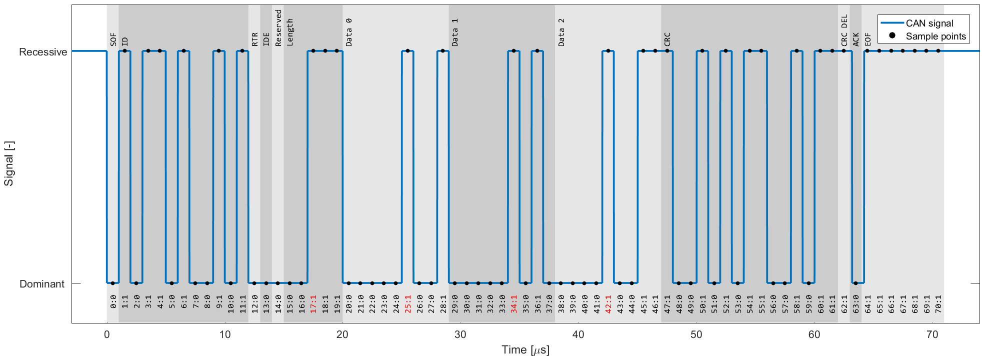


Active Error Flags
As we just learned, such a sequence is a violation of the bit stuffing rule — aka a ‘Bit Stuffing Error’.
Further, this error is visible to all CAN nodes on the network (in contrast to the ‘Bit Error’ that resulted
in this error flag being raised). Thus, the raising of error flags can be seen as a way of
«globalizing» the discovery of an error, ensuring that every CAN node is informed.
Note that the other CAN nodes will see the Active Error Flag as a Bit Stuffing Error. In
response they also raise an Active Error Flag.
As we’ll explain shortly, it is important to distinguish between the error flags. In particular, the first
error flag
(from the ‘discovering’ node) is often referred to as a ‘primary’ Active Error Flag, while
the error flags of
subsequent ‘reacting’ nodes are referred to as the ‘secondary’ Active Error Flag(s).
3 CAN error frame examples
Let’s look at three example scenarios:
Example 1: 6 bits of error flags
Here, all CAN nodes simultaneously discover that an error exists in a CAN message and raise their error
flags at the same time.
The result is that the error flags all overlap and the total sequence of dominant
bits lasts for 6 bits in total. All CAN nodes will in this case consider themselves the ‘discovering’ CAN
nodes.
This type of simultaneous discovery is less common in practice. However, it could e.g. happen as a
result of Form
Errors (such as a CRC delimiter being dominant instead of recessive), or if a CAN transmitter
experiences a bit error during the writing of a CRC field.


Example 2: 12 bits of error flags
Here, CAN node 1 transmits a dominant bit, but reads it as recessive — meaning that it discovers a Bit Error.
It immediately transmits a sequence of 6 dominant bits.
The other nodes only discover the Bit Stuffing Error
after the full 6 bits have been read, after which they simultaneously raise their error flags, resulting in
a subsequent sequence of 6 dominant bits — i.e. 12 in total.
Example 3: 9 bits of error flags
Here, CAN node 1 has already transmitted a sequence of 3 dominant bits when it discovers a Bit Error and
begins sending 6 dominant bits.
Once halfway through the primary Active Error Flag, nodes 2 and 3 recognize
the Bit Stuffing Error (due to the 3 initial dominant bits being followed by another 3 dominant bits) and
they begin raising their error flags. The result is that the sequence of dominant bits from error flags
becomes 9 bit long.

The above logic of raising error flags is reflected in what we call an ‘active’ CAN error frame.

Note in particular how the secondary error flags raised by various nodes overlap each other — and how the
primary and secondary flags may overlap as well. The result is that the dominant bit sequence from raised
error
flags may be 6 to 12 bits long.
This sequence is always terminated by a sequence of 8 recessive bits, marking the end of the error frame.
In practice, the active error frame may «begin» at different places in the erroneous CAN frame, depending on
when the
error is discovered. The result, however, will be the same: All nodes discard the erroneous CAN frame and
the
transmitting node can attempt to re-transmit the failed message.
Passive Error Flags
If a CAN node has moved from its default ‘active’ state to a ‘passive’ state (more on this shortly), it will only be
able to raise so-called ‘Passive Error Flags’. A Passive Error Flag is a sequence of 6 recessive bits as seen below.
In this case it’s relevant to distinguish between a Passive Error Flag raised by a transmitting node and a receiving
node.

Example 4: Transmitter is Error Passive
As shown in the illustration (Example 4), if a transmitter (such as CAN node 1 in our example) raises a
Passive Error Flag (e.g. in response to a Bit Error), this will correspond to a consecutive sequence of 6
recessive bits.
This is in turn detected as a Bit Stuffing Error by all CAN nodes. Assuming the other CAN
nodes are still in their Error Active state, they will raise Active Error Flags of 6 dominant bits. In other
words, a passive transmitter can still «communicate» that a CAN frame is erroneous.
Example 5: Receiver is Error Passive
In contrast, if a receiver raises a Passive Error Flag this is in practice «invisible» to all other CAN nodes
on the bus (as any dominant bits win over the sequence of recessive bits) — see also Example 5.
Effectively,
this means that an Error Passive receiver no longer has the ability to destroy frames transmitted by
other CAN nodes.

CAN error types
Next, let us look at what errors may cause CAN nodes to raise error flags.
The CAN bus protocol specifies 5 CAN error types:
- Bit Error [Transmitter]
- Bit Stuffing Error [Receiver]
- Form Error [Receiver]
- ACK Error (Acknowledgement) [Transmitter]
- CRC Error (Cyclic Redundancy Check) [Receiver]
We’ve already looked at Bit Errors and Bit Stuffing Errors briefly, both of which are evaluated at the bit
level. The remaining three CAN error types are evaluated at the message level.
Below we detail each error type:


#1 Bit Error
Every CAN node on the CAN bus will monitor the signal level at any given time — which means that a
transmitting CAN node also «reads back» every bit it transmits. If the transmitter reads a different data
bit level vs. what it transmitted, the transmitter detects this as a Bit Error.
If a bit mismatch occurs during the arbitration process (i.e. when sending the CAN ID), it is not
interpreted as a Bit Error. Similarly, a mismatch in the acknowledgement slot (ACK field) does not cause
a Bit Error as the ACK field specifically requires a recessive bit from the transmitter to be
overwritten by a dominant bit from a receiver.

#2 Bit Stuffing Error
As explained, bit stuffing is part of the CAN standard. It dictates that after every 5 consecutive bits of
the same logical level, the 6th bit must be a complement. This is required to ensure the on-going
synchronization of the network by providing rising edges. Further, it ensures that a stream of bits are not
mis-interpreted as an error frame or as the interframe space (7 bit recessive sequence) that marks the end
of a message. All CAN nodes automatically remove the extra bits.
If a sequence of 6 bits of the same logical level is observed on the bus within a CAN message (between the
SOF and CRC field), the receiver detects this as a Bit Stuffing Error aka Stuff Error.

#3 Form Error
This message-level check utilises the fact that certain fields/bits in the CAN message must always be of a
certain logical level. Specifically the 1-bit SOF must be dominant, while the entire 8-bit EOF field must be
recessive. Further, the ACK and CRC delimiters must be recessive. If a receiver finds that any of these are
bits are of an invalid logical level, the receiver detects this as a Form Error.

#4 ACK Error (Acknowledgement)
When a transmitter sends a CAN message, it will contain the ACK field (Acknowledgement), in which the
transmitter will transmit a recessive bit. All listening CAN nodes are expected to send a dominant bit in
this field to verify the reception of the message (regardless of whether the nodes are interested in the
message or not). If the transmitter does not read a dominant bit in the ACK slot, the
transmitter detects this as an ACK Error.

#5 CRC Error (Cyclic Redundancy Check)
Every CAN message contains a Cyclic Redundancy Checksum field of 15 bits. Here, the transmitter has
calculated the CRC value and added it to the message. Every receiving node will also calculate the CRC on
their own. If the receiver’s CRC calculation does not match the transmitter’s CRC, the
receiver detects this as a CRC Error.
CAN node states & error counters
As evident, CAN error handling helps destroy erroneous messages — and enables CAN nodes to retry the
transmission of
erroneous messages.
This ensures that short-lived local disturbances (e.g. from noise) will not
result in
invalid/lost data. Instead, the transmitter attempts to re-send the message. If it wins arbitration
(and there
are no errors), the message is successfully sent.
However, what if errors are due to a systematic malfunction in a transmitting node? This could
trigger an endless loop of sending/destroying the same message — jamming the CAN bus.
This is where CAN node states and error counters come in.


In short, the purpose of CAN error tracking is to confine errors by gracefully reducing the privileges of
problematic CAN nodes.
Specifically, let’s look at the three possible states:
-
Error Active: This is the default state of every CAN node, in which
it is able to
transmit data
and raise ‘Active Error Flags’ when detecting errors -
Error Passive: In this state, the CAN node is still able to
transmit data, but it now
raises
‘Passive Error Flags’ when detecting errors. Further, the CAN node now has to wait for an extra 8 bits
(aka
Suspend Transmission Time) in addition to the 3 bit intermission time before it can resume data
transmission (to
allow other CAN nodes to take control of the bus) -
Bus Off: In this state, the CAN node disconnects itself from the
CAN bus and can no
longer
transmit data or raise error flags
Every CAN controller keeps track of its own state and acts accordingly.
CAN nodes shift state depending on the value of their error counters. Specifically, every CAN node
keeps track on a Transmit Error Counter (TEC) and Receive Error Counter
(REC):
- A CAN node
enters the Error Passive state if the REC or TEC exceed 127 - A CAN node
enters the Bus Off state if the TEC exceeds 255
How do the error counters change?
Before we get into the logic of how error counters are increased/reduced, let us revisit the CAN error frame
as well
as the primary/secondary error flags.
As evident from the CAN error frame illustration, a CAN node that observes a dominant bit after its
own
sequence of 6
dominant bits will know that it raised a primary error flag. In this case, we can call this CAN
node the
‘discoverer’ of the error.
At first, it might sound positive to have a CAN node that repeatedly discovers errors and reacts promptly by
raising
an error flag before other nodes. However, in practice, the discoverer is typically also the culprit causing
errors
— and hence it is punished more severely as per the overview.

There are some additions/exceptions to the above rules, see e.g. this overview.
Most are pretty straight-forward based on our previous illustrative example. For example, it seems clear that CAN
node 1 would increase the TEC by 8 as it discovers the Bit Error and raises an error flag. The other nodes in
this
case increase their REC by 1.
This has the intuitive consequence that the transmitting node will quickly reach the Error Passive and eventually
Bus
Off states if it continuously produces faulty CAN messages — whereas the receiving nodes do not change state.
The case where a receiver raises the primary error flag may seem counter-intuitive. However, this could for
example
be the case if a receiver CAN node is malfunctioning in a way that causes it to incorrectly detect errors in
valid
CAN messages. In such a case, the receiver would raise the primary error flag, effectively causing an error.
Alternatively, it can happen in cases where all CAN nodes simultaneously raise error flags.
CAN/LIN data & error logger
The CANedge1 lets you easily
record data from 2 x CAN/LIN buses to an 8-32 GB SD card — incl. support for logging CAN/LIN errors. Simply
connect it to e.g. a car or truck to start logging —
and decode the data via free
software/APIs.
Further, the CANedge2
adds WiFi, letting you auto-transfer data to your own server — and update devices over-the-air.
learn
about the CANedge
Examples: Generating & logging error frames
We have now covered the theoretical basics of CAN errors and CAN error handling. Next, let us look at generating and
logging errors in practice. For this we will use a couple of CANedge devices — and for some tests a
PCAN-USB device.
Tip: Download the MF4 data for the tests to view the data in asammdf or CANalyzer.
download data
Test #1: No CAN bus errors
As a benchmark, we start with a test involving no CAN bus errors. Here, a CANedge2 ‘transmitter’ sends
data to another CANedge2 ‘receiver’ — and both log CAN bus errors.
By loading the MF4 log
file in the asammdf GUI we
verify that no CAN errors occurred during this test, which is to be expected.


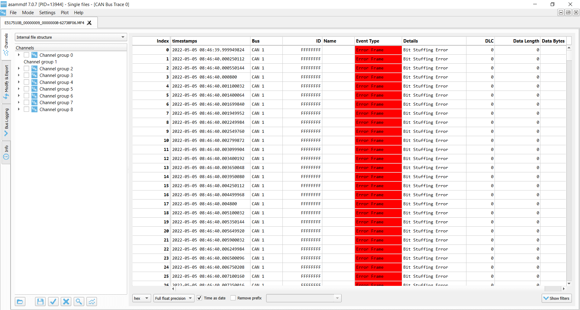
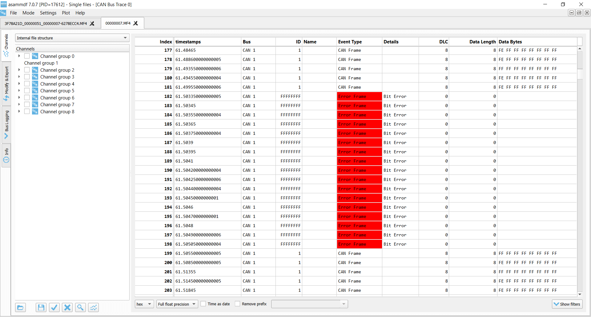
Test #2: Removing the CAN bus terminal resistor
In this test, we remove the CAN termination in the middle of a log session. This effectively corresponds to
immediately setting the bit level to dominant. As a result, the CANedge2 transmitter immediately starts
logging Bit Errors (which occur when it attempts to transmit a recessive bit, but reads a
dominant bit). The
CANedge2 Receiver logs Bit Stuffing Errors as it detects 6 consecutive dominant bits.
These errors are
recorded until the termination is added again.
Lack of termination is rarely a practical issue if you’re recording data from a vehicle, machine etc.
However, it’s a common issue when working with ‘test bench’ setups. Here, the lack of termination may
cause confusion as it can be difficult to distinguish from an inactive CAN bus. If in doubt, enabling
error frame logging on the CANedge can be useful in troubleshooting.

Transmitter Bit Errors

Receiver Bit Stuffing Errors
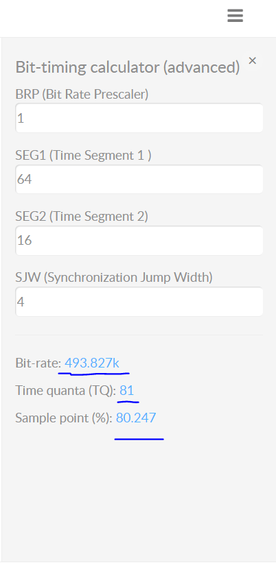
Test #3: Setting an incorrect baud rate
In this test we configure the CANedge receiver node to have a baud rate of 493.827K vs. the baud rate of the
transmitter of 500K. This is a fairly extreme difference and results in ACK Errors for the
transmitter and Bit
Stuffing Errors for the receiver.
In more realistic scenarios, smaller differences in the baud
rate
configuration of
various nodes may cause intermittent error frames and thus message loss.
This example is rather extreme. However, in practice we have sometimes seen CAN buses that use standard
bit rates
(250K, 500K, …), but with specific bit timing settings that differ from the ones that are typically
recommended
(and hence used by the CANedge). This will not lead to a complete shut-down of the communication, but
rather
periodic frame loss of a few percentages. To resolve this, you can construct an ‘advanced bit rate’ in
the
CANedge configuration, essentially setting up the bit-timing to better match the CAN bus you’re logging
from.

Transmitter ACK Error
Receiver Bit Stuffing Errors
Test #4: Removing the acknowledging CAN node
In this test, we use three CANedge units configured as follows:
-
CANedge1: Configured to
acknowledge data -
CANedge2 A:
Configured in ‘silent mode’ (no acknowledgement) -
CANedge2 B:
Configured to transmit a CAN frame every 500 ms
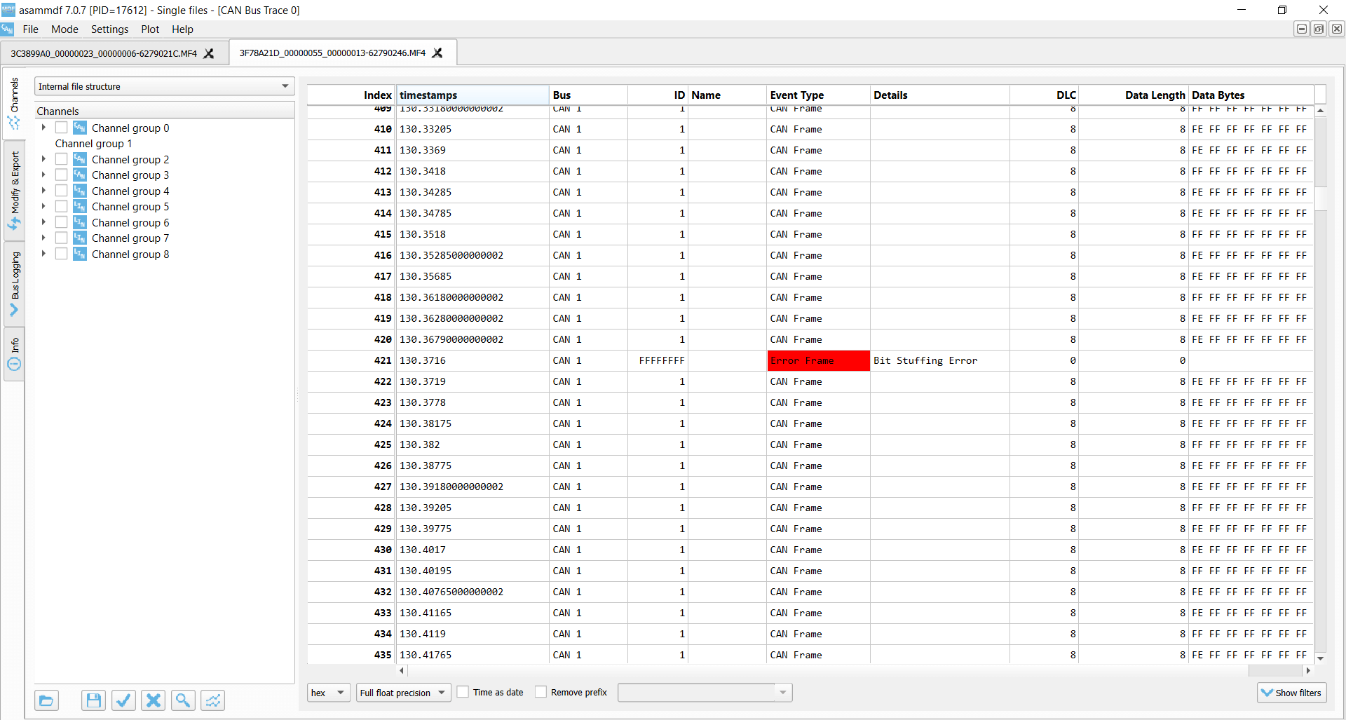
In the default setup, data is transmitted by the CANedge2 B onto the CAN bus and recorded with no errors.
However, if we remove the CANedge1 from the bus there are no longer any CAN nodes to acknowledge the frames
sent by the transmitter.
As a result, the transmitter detects ACK Errors. In response, it increases its
Transmit Error Counter and raises Active Error Flags onto the CAN bus. These are in turn
recorded by CANedge2 A (which silently monitors the bus) as Form Errors.
This is due to the fact that the transmitter raises them upon identifying the lack of a dominant
bit in the ACK slot. As soon as a dominant bit is observed by the receiver in the subsequent EOF field
(which should be recessive), a Form Error is detected.
As evident, the transmitter broadcasts 16 Active Error Flags as its TEC is increased from 0 to 16 x 8 =
128.
The transmitter has now exceeded the threshold of a TEC of 127 and enters Error Passive mode. As a
result,
the transmitter still experiences ACK Errors, but now only raises Passive Error Flags (not visible to
the
receiver). At this point, the transmitter keeps attempting to transmit the same frame — and the receiver
keeps recording this retransmission sequence.
This type of error is one we often encounter in our support tickets. Specifically, users may be trying to
use our CAN loggers to record data from a single CAN node (such as a sensor-to-CAN module like our
CANmod). If they decide to enable ‘silent mode’ on the CANedge in such an installation, no CAN nodes
will acknowledge the single CAN node broadcasting data — and the result will either be empty log files,
or log files filled with retransmissions of the same CAN frame (typically at very high frequency).


Transmitter ACK Errors

Receiver Form Errors
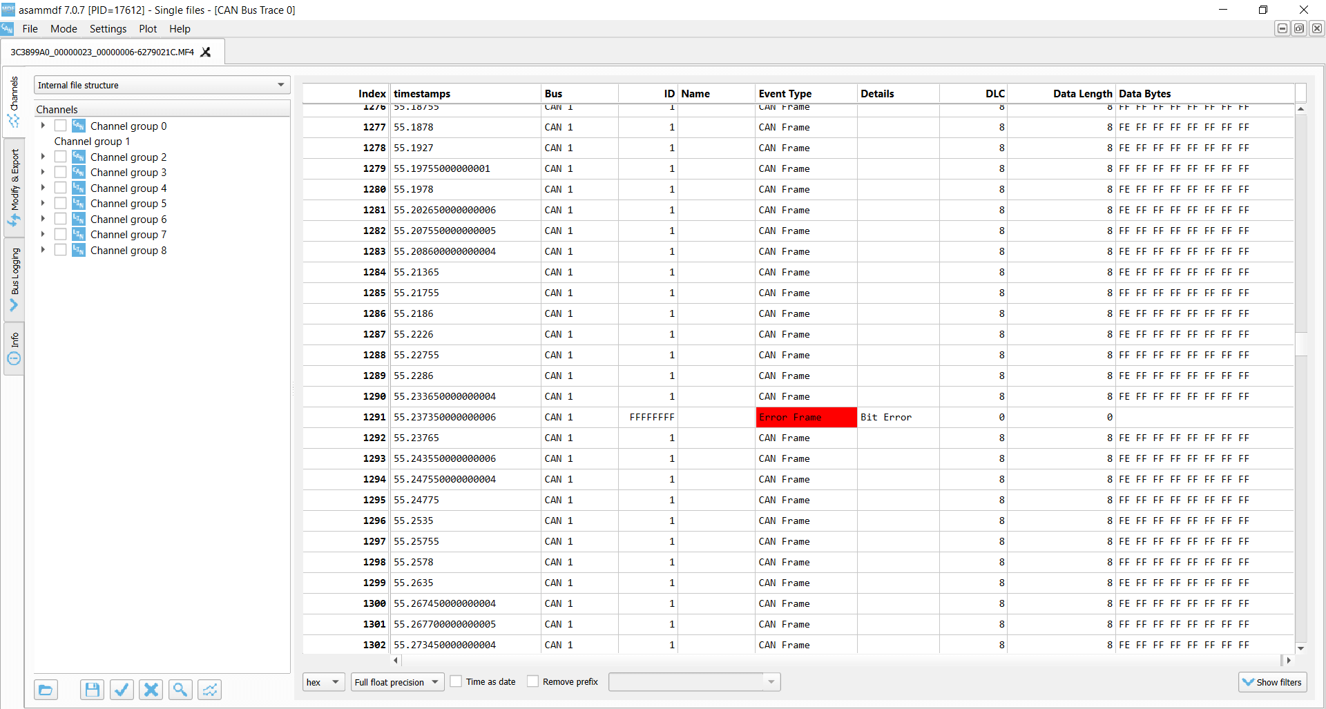
Test #5: CAN frame collisions (no retransmission)
When setting up a CAN bus, it is key to avoid overlapping CAN IDs. Failing to do so can result in frame
collisions
as two CAN nodes may both believe they’ve won the arbitration — and hence start transmitting their frames at
the same time.
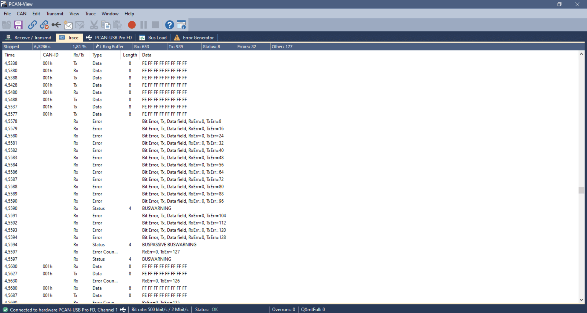
To simulate this, we use the same setup as in test #4. In addition, we connect a PCAN-USB device as a
secondary
transmitter.
The CANedge2 transmitter is now configured to output a single CAN frame every 10 ms with CAN ID 1 and a
payload of
eight 0xFF bytes. Further, we configure the CANedge2 to disable retransmission of frames that were disrupted
by
errors. The PCAN-USB outputs an identical CAN frame every 2 ms with the 1st byte of the payload changed to
0xFE. The
PCAN device has retransmissions enabled.
This setup quickly creates a frame collision, resulting in the CANedge and PCAN transmitters detecting a
Bit
Error.
In response to this, both raise an Active Error Flag, which is detected as a Bit Stuffing
Error by the
CANedge
receiver. The PCAN device immediately attempts a retransmission and succeeds, while the CANedge waits with
further
transmission until the next message is to be sent.
This type of error should of course never happen in e.g. a car, since the design and test processes will
ensure
that all CAN nodes communicate via globally unique CAN identifiers. However, this problem can easily
occur if
you install a 3rd party device (e.g. a sensor-to-CAN module) to inject data into an existing CAN bus. If
you do
not ensure the global uniqueness of the CAN IDs of external CAN nodes, you may cause frame collisions
and hence
errors on the CAN bus. This is particularly important if your external CAN node broadcasts data with
high
priority CAN IDs as you may then affect safety critical CAN nodes.


USB-to-CAN transmitter Bit Error
CANedge transmitter Bit Error
CANedge receiver Bit Stuffing Error
Test #6: CAN frame collisions (incl. retransmission)
In this test, we use the same setup as before, but we now enable retransmissions on the CANedge2 transmitter.
In this case, the frame collision results in a sequence of subsequent frame collisions as both the CANedge2
and the PCAN-USB device attempt to re-transmit their disrupted messages.
Due to the resulting Bit Errors, both raise a total of 16 Active Error Flags, which are detected as
Bit Stuffing Errors
by the silent CANedge2 receiver. Both transmitters then enter Error Passive mode and stop raising Active Error
Flags, meaning none of them can destroy CAN frames on the bus. As a result, one of the transmitters will
succeed in transmitting a full message, thus ending the retransmission frenzy — and enabling both devices to
resume transmission. However, this only lasts for a few seconds before another collision occurs.
The collision handling is a good example of how effective the CAN error handling is at ‘shutting down’
potentially
problematic sequences and enabling CAN nodes to resume communication. If a frame collision occurs, it is likely
that both CAN nodes will be set up to attempt retransmission, which would cause a jam if not for the error
handling and confinement.
USB-to-CAN transmitter Bit Errors x 16
CANedge transmitter Bit Errors x 16

CANedge receiver Bit Stuffing Errors x 16
Similar to CAN bus errors, the LIN protocol also specifies a set of four error types, which we outline briefly below.
The CANedge supports both CAN/LIN error frame logging.
As for the CAN CRC Error, this error type implies that a LIN node has calculated a different checksum vs. the one
embedded in the LIN bus frame by the transmitter. If you’re using the CANedge as a LIN Subscriber, this error
may indicate that you’ve configured the device ‘frame table’ with incorrect identifiers for some of the LIN
frames on the bus.
This can in turn be used to ‘reverse engineer’ the correct lengths and IDs of proprietary LIN frames via a
step-by-step procedure. See the CANedge Docs for details.
These occur if a specific part of the LIN message does not match the expected value, or if there is a mismatch
between what is transmitted vs. read on the LIN bus.
This error indicates an invalid synchronization field in the start of the LIN frame. It can also indicate a large
deviation between the configured bit rate for a LIN node vs. the bit rate detected from the synchronization
field.
Transmission errors can occur for LIN identifiers registered as SUBSCRIBER messages. If there are no nodes
responding to a SUBSCRIBER message, a transmission error is logged.
Example use cases for CAN error frame logging
CAN bus diagnostics in OEM prototype vehicles
An automotive OEM may have the need to record CAN error frames in the field during late stage prototype
testing. By deploying a CANedge, the OEM engineering team will both be able to troubleshoot issues based on
the actual CAN signals (speed, RPM, temperatures) — as well as issues related with the lower layer CAN
communication in their prototype systems. This is particularly vital if the issues of interest are
intermittent and e.g. only happen once or twice per month. In such scenarios, CAN bus interfaces are not
well suited — and it becomes increasingly relevant to have a cost-effective device to enable scalable
deployments for faster troubleshooting.


Remotely troubleshooting CAN errors in machinery
An OEM or aftermarket user may need to capture rare CAN error events in their machines. To do so, they deploy
a CANedge2 to record the CAN data and related error frames — and automatically upload the data via WiFi to
their own cloud server. Here, errors are automatically identified and an alert is sent to the engineering
team to immediately allow for diagnosing and resolving the issue.
FAQ
No, error frame logging is a highly specific functionality — and only relevant if you know that you need to
record this information. Typically, it’s mainly of value during diagnostics by OEM engineers — and less so for
aftermarket users. In addition, if systematic errors occur they can quickly bloat the log file size.
With the CANedge2 you can of course enable/disable error frame logging over-the-air.
Yes, the CANedge is able to record all CAN/LIN error types. It does, however, not currently record its own error
counter status as this is deemed less relevant from a logging perspective.
The CANedge is only able to raise error flags onto the CAN bus if it is configured in its ‘normal’ mode, in which
it is also able to transmit messages. If in ‘restricted’ mode it can listen to CAN frames and acknowledge CAN
frames — but not raise Active Error Flags onto the bus. In ‘monitoring’ mode (aka ‘silent mode’) it can listen
to the CAN bus traffic, but not acknowledge messages nor raise Active Error Flags.
The CANedge will always record internal CAN/LIN error frames.
If a CAN frame is erroneous, resulting in an error frame, the CANedge generally only records the error type —
without any data related to the erroneous frame (beyond the timestamp). One exception to this rule is for
acknowledgement errors, where the CANedge will still record unacknowledged CAN frames (incl. from retransmission
attempts).
Some researchers have pointed out the risk that ‘bad actors’ could utilize the CAN bus error handling
functionality to enforce remote ‘bus off’ events for safety-critical ECUs. This is a good example of why CAN bus
data loggers & interfaces like the CANedge2 with remote
over-the-air data transfer and updates need to be highly secure (see also our intro to CAN
cybersecurity). For a nice overview of a remote bus off attack, see this
intro by Adrian Colyer.
For more intros, see our guides section — or download the
‘Ultimate Guide’ PDF.
Need to log CAN bus data & errors?
Get your CAN logger today!
Recommended for you