
Canon LBP 5050 /Постоянно мигает индикатор застрявшей бумаги, хотя бумаги там нет, внимательно проверял. Что можно сделать?
Спасибо
Канон 5050 зарядили в сервисе в черный картридж чип от красного. Обойти можно? Basil.74@mail.ru
После заправки картриджей бледная передача цвета, примерно на 40-50%.
отпечатает 2-3 листа и орет просит калибровку. при неоднократных попыток выполнить калибровку — не выполняет. для продолжения печати нужно выключить …
При печати изображение повторяется бледно, скорее всего температура запекания тонера не в ТУ и неисправен термистор TH 802
canon lbp5050 почти новый. Печатает цветами какими сам хочет. Коррекция неправильного регистра цветов не помогает. Помогите пожалуйста кто знает что …
Замучила ошибка Could not properly adjust the printing position of each of the toner cartridges.
Чем отличается принтер CANON I-SENYS LBP 5050 от CANON LBP 5050? У меня второй тип . При включении моргает зеленый индикатор , затем независимо от …
Не могу снять вал подачи бумаги. Есть у кого схема разборки данного аппарата?
Расползаются цвета. С одного края нормалько, но чем ближе к другому, тем больше
сдвиг цветов. Смещение около 2-:-3 мм на листе А4
Индикатор состояния не перестает мигать, сам принтер выпускает пустой лист. Что делать?
Проблема с принтером Canon LBP5050 , документ ставится в очередь и не печатает, пишет: Check the following:
— Is the printer turned on?
— Is the …
Принтер не печатает Фотографии! Ни на простой, ни на фото-бумаге. Горит на принтере кнопка, что отсутствует бумага (… Текст печатает. В чем может …
полосит при печати, заправил, распечатал, все равно идут горизонтальные полосы
После заправки картриджей печатать не хочет и выдаёт: (Черный, Желтый, Пурпурный, Бирюзовый)
Возможно, возникла ошибка соединения картриджей с …
Не могу найти прошивку на этот принтер, может кто-нибудь поделиться?
При загрузке плотной бумаги в лоток не видит её. При этом никаких попыток захватить бумагу не предпринимает. Раньше всё удавалось.
При запуске принтера пишет :Возможно, вставлены картриджи с тонером, которые обеспечат печать низкого качества и ускоряет срок службы и т.д., или …
При печати на плотной бумаге появляется полоса отслоения краски (она как расплавленная пленка отклеивается от бумаги).
Полоса посредине листа …
после заправки картриджев и замены чипов, принтер стал печатать со смещением
Принтер LBP5050 перестал печатать PDF-файлы. Первое время после покупки печатал, а потом вдруг расхотел…Принтеру всего-то 4 месяца от …
принтер игнорирует ручную подачу бумаги пока в основном лотке есть бумага,хотя захватывает ее ,даже если в настройках источником бумаги указана ручная …
Code
Detection details
0000
Description: Abnormal output from toner remaining detection sensor
(Yellow)
Cause: Memory controller PCB defect, DC controller PCB defect, toner
cartridge defect
0001
Description: Abnormal output from toner remaining detection sensor
(Magenta)
Cause: Memory controller PCB defect, DC controller PCB defect, toner
cartridge defect
0002
Description: Abnormal output from toner remaining detection sensor
(Cyan)
Cause: Memory controller PCB defect, DC controller PCB defect, toner
cartridge defect
0003
Description: Abnormal output from toner remaining detection sensor
(Black)
Cause: Memory controller PCB defect, DC controller PCB defect, toner
cartridge defect
E066
Environment sensor abnormality
Description: Environment sensor abnormality
Cause: Environment sensor defect, DC controller PCB defect
E100
ITB/TOP sensor failed
Description: ITB/TOP sensor failed.
Cause: ITB/TOP sensor defect, DC controller PCB defect
E100
Scanner unit, laser unit, BD abnormality
0000
Description: Yellow optical assembly failure.
Cause: Laser scanner defect, DC controller PCB defect
0001
Description: Magenta optical assembly failure.
Cause: Laser scanner defect, DC controller PCB defect
0002
Description: Cyan optical assembly failure.
Cause: Laser scanner defect, DC controller PCB defect
0003
Description: Black optical assembly failure.
Cause: Laser scanner defect, DC controller PCB defect
E110
BD correction control failure
Description: The machine does not change to the scanner ready status, after
starting BD control.
Cause: Laser scanner unit defect, DC controller PCB defect
E196
DCON ROM abnormality
DC controller PCB ROM update failed.
E197
Engine communication error
0000
Internal communication error
E198
DC controller memory failure
Description: DC controller memory failure.
Cause: DC controller PCB defect
E747
EEPROM error
Treatment
— Check the connector of the DC controller PCB.
— Replace toner cartridge
— Replace DC controller PCB
— Check the connector of the environment sensor, DC controller PCB.
— Replace environment sensor
— Replace DC controller PCB
— Check the connector of the ITB unit, DC controller PCB.
— Replace ITB unit
— Replace DC controller PCB
— Check the connector of the laser scanner unit, DC controller PCB.
— Replace laser scanner unit
— Replace DC controller PCB
— Replace the laser scanner unit
— Replace DC controller PCB
— Replace DC controller PCB
— Replace DC controller PCB
— Replace main controller PCB
— Replace DC controller PCB
Chapter 5
5-5
-
Contents
-
Table of Contents
-
Troubleshooting
-
Bookmarks
Quick Links
Service Manual
LBP5050 Series
Aug 13 2008
Related Manuals for Canon LBP5050 Series
Summary of Contents for Canon LBP5050 Series
-
Page 1: Service Manual
Service Manual LBP5050 Series Aug 13 2008…
-
Page 3
Canon will release technical information as the need arises. In the event of major changes in the contents of this manual over a long or short period, Canon will issue a new edition of this manual. -
Page 4: Symbols Used
Introduction Symbols Used This documentation uses the following symbols to indicate special information: Symbol Description Indicates an item of a non-specific nature, possibly classified as Note, Caution, or Warning. Indicates an item requiring care to avoid electric shocks. Indicates an item requiring care to avoid combustion (fire). Indicates an item prohibiting disassembly to avoid electric shocks or problems.
-
Page 5
Introduction The following rules apply throughout this Service Manual: 1. Each chapter contains sections explaining the purpose of specific functions and the relationship between electrical and mechanical systems with refer- ence to the timing of operation. In the diagrams, represents the path of mechanical drive; where a signal name accompanies the symbol , the arrow indicates the direction of the electric signal. -
Page 7: Table Of Contents
Contents Contents Chapter 1 PRODUCT DESCRIPTION 1.1 Features …………………………1- 1 1.1.1 Feature …………………………….1- 1 1.2 Product Specifications ……………………..1- 1 1.2.1 Product Specifications ……………………….. 1- 1 1.3 Detailed Specifications ……………………..1- 2 1.3.1 Print Speed…………………………..1- 2 1.4 Name of Parts………………………..1- 3 1.4.1 External View…………………………..
-
Page 8
Contents 2.5.1 Overview/Configuration……………………….2- 10 2.5.1.1 Outline………………………………2- 10 2.5.2 Detecting Jams …………………………2- 11 2.5.2.1 Jam Detection Outline…………………………..2- 11 2.5.2.2 Delay Jams ……………………………… 2- 11 2.5.2.3 Stationary Jams …………………………….2- 11 2.5.2.4 Other Jams ……………………………… 2- 11 2.5.3 Cassette Pickup …………………………2- 12 2.5.3.1 Separation Roller Method ………………………… -
Page 9
Contents 3.1.10.1 Before Removing the Main Motor ……………………….3- 8 3.1.10.2 Removing the Main Motor …………………………3- 8 3.1.11 Operation Panel Unit ……………………….. 3- 9 3.1.11.1 Before Removing the Control Panel……………………….3- 9 3.1.11.2 Removing the Control Panel …………………………3- 9 3.1.12 DC Controller PCB…………………………. -
Page 10
Contents 4.4 Cleaning …………………………4- 1 4.4.1 Cleaning Point…………………………..4- 1 4.4.2 Pickup Roller…………………………..4- 1 4.4.3 Separation Roller …………………………4- 2 4.4.4 Front Fixing Guide …………………………4- 2 4.4.5 Feed Guide …………………………..4- 2 Chapter 5 TROUBLESHOOTING 5.1 MEASUREMENT AND ADJUSTMENT…………………. 5- 1 5.1.1 Test Print…………………………….5- 1 5.1.1.1 Test Pages……………………………… -
Page 11: Chapter 1 Product Description
Chapter 1 PRODUCT DESCRIPTION…
-
Page 13
Contents Contents 1.1 Features …………………………….1-1 1.1.1 Feature………………………………..1-1 1.2 Product Specifications…………………………1-1 1.2.1 Product Specifications …………………………… 1-1 1.3 Detailed Specifications …………………………1-2 1.3.1 Print Speed ………………………………1-2 1.4 Name of Parts……………………………1-3 1.4.1 External View ………………………………1-3 1.4.2 Cross Sectional View …………………………….. 1-4 1.5 Using the Machine ……………………………1-5 1.5.1 Control Panel ……………………………… -
Page 15: Features
Chapter 1 1.1 Features 1.1.1 Feature 0018-8898 LBP5050N / LBP5050 1. Small and low-cost printer The printer uses a flat in-line cartridge method for the first time in the small printer. This lowers the height and reduces the printer size. The printer uses the transfer pad and the separation roller to reduce the parts expenses.
-
Page 16: Detailed Specifications
Chapter 1 Operating environment 10 to 80%RH (Humidity range) Operating environment l810.6 to 1013.3 hpa (0.8 to 1.0 atm) (Atmospheric pressure) Noise During standby: Background noise level During operation: 48 dB (black and white)/47 dB (color) Power supply rating 110-127 V (±10%), 50/60 Hz (±2 Hz), 220-240 V (±10%), 50/60 Hz (±2 Hz) Power consumption (Maximum) LBP5050: Approx.
-
Page 17: Name Of Parts
Chapter 1 1.4 Name of Parts 1.4.1 External View 0018-8908 LBP5050N / LBP5050 F-1-1 Front Cover Paper Guides Manual Feed Slot Power Switch Paper Cassette Manual Feed Slot Cover Manual Feed Guide Output Tray F-1-2 Rear Cover ERR Indicator (Orange) Power Socket USB Port 100 Indicator (Green)
-
Page 18: Cross Sectional View
Chapter 1 1.4.2 Cross Sectional View 0018-7829 LBP5050N / LBP5050 [14] [13] [12] [11] [10] F-1-3 T-1-2 [1] Fixing unit [8] ITB unit [2] Delivery roller [9] Pickup roller [3] Cartridge [10] Separation roller [4] Laser scanner unit [11] Registration roller [5] Photosensitive drum [12] Secondary transfer roller [6] Manual feed roller…
-
Page 19: Using The Machine
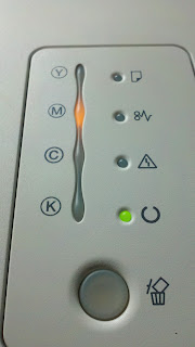
Chapter 1 1.5 Using the Machine 1.5.1 Control Panel 0018-8909 LBP5050N / LBP5050 F-1-4 Functions of the LEDs T-1-3 Name Status Description Printing cannot be performed because a toner cartridge needs to be replaced, or a toner cartridge is not Blinking installed properly.
-
Page 20: Safety
Chapter 1 1.6 Safety 1.6.1 Safety of the Laser Light 0019-1638 LBP5050N / LBP5050 Laser beam radiation may pose a danger to the human body. A laser scanner mounted on the machine is sealed with the protection housing and external cover to prevent the laser beam from leaking to the outside.
-
Page 21: Points To Note At Disassembly/Installation Procedure
Chapter 1 F-1-7 1.6.4 Points to note at disassembly/installation procedure 0019-1647 LBP5050N / LBP5050 At disassembly/installation procedure, make sure to follow the instruction below to proceed. 1. Be sure to unplug the power code before disassembly/installation. 2. At installation, follow the procedure in the reverse order of disassembly unless otherwise instructed. 3.
-
Page 23: Chapter 2 Technical Reference
Chapter 2 TECHNICAL REFERENCE…
-
Page 25
Contents Contents 2.1 Functional Configuration ………………………….2-1 2.1.1 Outline………………………………..2-1 2.2 Basic Sequense…………………………..2-1 2.2.1 Basic Sequence of Operation …………………………. 2-1 2.3 LASER EXPOSURE SYSTEM………………………..2-2 2.3.1 Overview/Configuration …………………………..2-2 2.3.1.1 Outline……………………………………2-2 2.3.2 Laser Scanner Motor Control…………………………. 2-2 2.3.2.1 Fault Detection ………………………………….2-2 2.4 IMAGE FORMATION SYSTEM ……………………..2-3 2.4.1 Overview/Configuration ………………………….. -
Page 26
Contents 2.6.2.1.1 Speed control on small size paper (Throughput down control)………………….2-13 2.6.2.2 Fixing Temperature Control …………………………….2-13 2.6.2.2.1 Fixing temperature control…………………………….2-13 2.6.3 Protective Functions…………………………….. 2-14 2.6.3.1 Protective function ………………………………..2-14 2.6.3.2 Fixing unit failure detection…………………………….2-14 2.7 EXTERNAL AND CONTROLS SYSTEM ………………….. 2-14 2.7.1 Power Supply ………………………………. -
Page 27: Functional Configuration
Chapter 2 2.1 Functional Configuration 2.1.1 Outline 0019-2379 LBP5050N / LBP5050 The machine may be broadly divided into the following 6 functional blocks: engine control system, laser exposure system, image formation system, pickup/trans- port/delivery system, fixing system, and externals/auxiliary control system. Laser exposure system Image formation system Pickup/transport/delivery system…
-
Page 28: Laser Exposure System
Chapter 2 2.3 LASER EXPOSURE SYSTEM 2.3.1 Overview/Configuration 2.3.1.1 Outline 0018-6525 LBP5050N / LBP5050 The laser scanner system forms the latent image on the photosensitive drum according to the VIDEO signals sent from the main controller. The main components of the laser scanner unit are the laser driver and the scanner motor unit and are controlled by the signals sent from the DC controller. Laser driver Polygon mirror Scaner motor unit…
-
Page 29: Image Formation System
Chapter 2 2.4 IMAGE FORMATION SYSTEM 2.4.1 Overview/Configuration 2.4.1.1 Outline 0018-6673 LBP5050N / LBP5050 The image-formation system is the central hub of the printer. It forms the toner image on the media. The following are the main components of the image-formation system: — Four toner cartridges — ITB — Laser scanner unit…
-
Page 30: Latent Image Formation Block
Chapter 2 : Media path : Direction of drum rotation : Block Delivery : Step Fixing Latent image formation 7. Fixing 2. Laser-beam exposure Development 1. Primary charging 3. Development ITB cleaning Photosensitive drum cleaning 8. ITB cleaning 9. Drum cleaning 6.
-
Page 31: Transfer Block
Chapter 2 Toner adheres to the electrostatic latent image on the photosensitive drum, which becomes visible. Step 3: Development Toner acquires a negative charge from the friction that occurs when the developing cylinder rotates against the developing blade. When the negatively charged toner comes in contact with the drum, it adheres to the latent image because the drum surface has a higher potential.
-
Page 32: Fixing Block
Chapter 2 Media ITB drive roller Secondary transfer roller F-2-10 2.4.1.6 Fixing block 0018-6684 LBP5050N / LBP5050 The toner image is fixed onto the print media. Step 7: Fixing The printer uses an on-demand fixing method to fix the toner image onto the media. The toner image is permanently affixed to the print media by the heat and pressure.
-
Page 33: Photosensitive Drum Cleaning Block
Chapter 2 Positive potential waste toner Cartridge Negative potential waste toner Photosensitive drum ITB cleaning roller Partition sheet ITB cleaning brush Sweeper strip DC bias DC bias F-2-12 2.4.1.8 Photosensitive drum cleaning block 0018-6686 LBP5050N / LBP5050 The waste toner is cleared from the photosensitive drum surface. Step 9: Drum cleaning The cleaning blade scrapes the waste toner off the surface of the photosensitive drum.
-
Page 34: Image Stabilizaton Control
Chapter 2 Developing Blade Primary charging high-voltage high-voltage high-voltage generation circuit generation circuit generation circuit Cartridge Photosensitive drum Primary transfer pad ICLB ICLR ITB cleaning unit Secondary transfer roller ITB cleaning brush ITB cleaning roller Secondary transfer Primary transfer high-voltage high-voltage high-voltage high-voltage…
-
Page 35: Image Gradation Correction Control (D-Half Control)
Chapter 2 — When a customer requests the calibration MEMO: — When the calibration is executed, sheet counter reading and elapsed time timer are cleared. — Calibration is not executed in sleep mode. — At power ON, calibration is suspended until the initial print process is completed and the machine is ready or until 15 min passes after the power ON. The time setting can be changed from option >…
-
Page 36: Pickup/Feeding/Delivery System
Chapter 2 Photosensitive drum Wider nip width Narrow nip width Transfer pad Transfer roller <Pad transfer method> <Roller transfer method> F-2-15 2.5 Pickup/Feeding/Delivery System 2.5.1 Overview/Configuration 2.5.1.1 Outline 0018-6692 LBP5050N / LBP5050 The pickup-and-feed system picks up and feeds the print media. It consists of several types of feed rollers. The main components of the pickup-and-feed system are the following: Pickup source: — Cassette…
-
Page 37: Detecting Jams
Chapter 2 Description Signal Driver CASSETTE PICKUP SOLENOID DRIVE Cassette pickup solenoid SL705 DC controller signal Cassette media presence SR601 CASSETTE MEDIA PRESENCE signal DC controller sensor Top of page sensor SR602 TOP OF PAGE signal DC controller Loop sensor SR603 LOOP DETECTION signal DC controller…
-
Page 38: Cassette Pickup
Chapter 2 2.5.3 Cassette Pickup 2.5.3.1 Separation Roller Method 0018-6697 LBP5050N / LBP5050 The printer has a separation roller method to prevent multiple sheets of media from entering to the printer. The paper separation roller follows the rotational direction of the pick-up roller because it does not have its own driving force. — Normal-feed The separation roller is driven by the pickup roller through a sheet of print media.
-
Page 39: Various Control Mechanisms
Chapter 2 — Thermal fuse (FU1): Prevents the fixing heater temperature from rising abnormally high The thermal fuse is located at the center of the fixing heater. If the temperature of the fixing heater rises abnormally high, the thermal fuse blows to interrupt power supply to the fixing heater. These temperature controls in the fixing unit are performed by the fixing control circuit and the fixing heater safety circuit according to the commands from the DC controller.
-
Page 40: Protective Functions
Chapter 2 T-2-5 Speed Paper type Setting on driver 1st temperature to 5th temperature 6/5 speed Plain paper (75 to 90 g/m2) Plain paper 183 to 175 (monochrome) Thin paper (60 to 74 g/m2) Plain paper L 164 to 130 1/1 speed (color) Plain paper (75 to 90 g/m2) Plain paper…
-
Page 41: Other Function
Chapter 2 AC input DC controller Fuse FU901 Noise filter Fixing control circuit Power switch SW801 Fuse FU801 Fixing power supply Noise filter Only for the 200V model FREQSNS Frequency detection circuit REM24V Rectifying circuit +24V +3.3V +24V +3.3V generation generation circuit circuit…
-
Page 42: Motor Control
Chapter 2 The DC controller controls the operational sequence of the printer. DC controller Fixing unit Motor Fixing AC input power supply Solenoid Switch Low-voltage power supply Sensor High-voltage Cartridge power supply Sensor ITB unit Main controller Laser/scanner unit F-2-21 T-2-6 Symbol for component Name…
-
Page 43: Safety
If properly connected with a bi-directional interface, an external device may be used to check the printer status. When printing is executed in a Microsoft Windows or Macintosh environment, CAPT (Canon Advanced Printing Technology) serves to reduce processing speed and enhance the ease of operation to provide a user-friendly printing environment. To that end, CPU is designed for the following: — The print data from the application is turned into dot data and sent to the printer without conversion into the printer’s page description language (PDL).
-
Page 44
Chapter 2 16MB 4Kbit NIC I/F TRANSCEIVER NVRAM SDRAM Connector (IC2S) (IC7) Control system (IC3) Control system Flash ROM SDRAM (IC5) (IC11) (IC12) NW I/F controller Video(K) MEMC Video(C) Video(Y) Video(M) USB2.0 Connector ASIC (IC6) ASIC (IC1) F-2-23 T-2-10 Name Description ASIC handle the image data… -
Page 45: Chapter 3 Disassembly And Assembly
Chapter 3 DISASSEMBLY AND ASSEMBLY…
-
Page 47
Contents Contents 3.1 EXTERNAL AND CONTROLS SYSTEM ……………………3-1 3.1.1 Rear Cover ………………………………3-1 3.1.1.1 Before Removing the Rear Door…………………………….3-1 3.1.1.2 Removing the Rear Door ………………………………3-1 3.1.2 Rear Side Cover …………………………….. 3-1 3.1.2.1 Before Removing the Rear Side Cover …………………………..3-1 3.1.2.2 Removing the Rear Side Cover…………………………….3-1 3.1.3 Rear Upper Cover ……………………………. -
Page 48
Contents 3.3 IMAGE FORMATION SYSTEM ……………………..3-15 3.3.1 Intermediate Transfer Unit…………………………… 3-15 3.3.1.1 Before Removing the ITB Unit …………………………….3-15 3.3.1.2 Removing the ITB Unit ………………………………3-16 3.4 PICKUP/FEEDING/DELIVERY SYSTEM………………….. 3-17 3.4.1 Cassette Pickup Roller …………………………..3-17 3.4.1.1 Removing the Pickup Roller…………………………….3-17 3.4.2 Cassette Separation Roller …………………………… -
Page 49: External And Controls System
Chapter 3 3.1 EXTERNAL AND CONTROLS SYSTEM 3.1.2 Rear Side Cover 3.1.2.1 Before Removing the Rear Side Cover 3.1.1 Rear Cover 0018-7852 LBP5050N / LBP5050 3.1.1.1 Before Removing the Rear Door 1) Remove the right cover. (page 3-2)[Removing the Right Cover] 0018-7071 LBP5050N / LBP5050 3.1.2.2 Removing the Rear Side Cover…
-
Page 50: Right Cover
Chapter 3 row. 5) Free the claw [3] and remove the right cover [2]. F-3-5 3.1.4 Right Cover 3.1.4.1 Removing the Right Cover 0018-7065 LBP5050N / LBP5050 1) Remove the cassette [1]. F-3-9 3.1.5 Left Cover 3.1.5.1 Removing the Left Cover 0018-7066 LBP5050N / LBP5050 1) Remove the cassette [1].
-
Page 51: Upper Cover
Chapter 3 3) Free the 2 claws [1] and open the left cover [2] in the direction of the arrow 1) Remove the upper cover assembly [1]. [A]. — 1 flat cable [2] 4) Free the claw [3] and open the left cover [2] in the direction of the arrow — 1 screw [3] [B].
-
Page 52
Chapter 3 F-3-19 7) Close the front door [1]. F-3-15 2) Open the front door [1]. F-3-20 Open the manual pickup slot cover [1] in the direction of the arrow [A]. 9) Open the manual pickup tray assembly [2] in the direction of the arrow [B].
 -
Page 53: Main Drive Unit
Chapter 3 [ D ] [ A ] [ B ] [ C ] F-3-23 12) Remove the paper pass guide [1]. F-3-27 17) Remove the shaft [1] of the right arm in the direction of the arrow [A] and lift the right arm [2] in the direction of the arrow [B]. 18) Remove the shaft [3] of the left arm in the direction of the arrow [C] and lift the left arm [4] in the direction of the arrow [D].
-
Page 54: Removing The Main Drive Assembly
Chapter 3 6) Remove the upper cover assembly. (page 3-3)[Removing the Upper Cover Assembly] 7) Remove the main controller PCB. (page 3-11)[Removing the Main Con- troller PCB]
Remove the low-voltage power supply assembly. (page 3-11)[Remov- ing the Low-Voltage Power Supply Assembly] 9) Remove the DC controller PCB. -
Page 55
Chapter 3 F-3-35 Free the 2 claws [1] in the direction of the arrow, remove the link shaft stopper [2] in the direction of the arrow and remove the link shaft [3]. F-3-37 Points to Note at Installation Check to see that hook [2] of the gear [1] of the sub drive assembly is situated at the correct position as shown in the following figure. -
Page 56: Sub Driver Unit
Chapter 3 F-3-39 Points to Note At Parts Replacement The dowel pin may come off in certain directions of the shaft [1]. Be careful not to drop or lose the dowel pin [2]. When installing the sub drive assembly, be sure to fix the dowel pin [2] to the shaft [1], rotate the shaft [1] and the gear [3], fit the dowel pin [2] into the pin holder [4] of the gear horizontally and then install the assembly.
-
Page 57: Operation Panel Unit
Chapter 3 F-3-40 2) Slide the motor cover [1] downward and remove it. — 1 connector [2] — 2 claws [3] 3) Remove the motor cover [1] from the harness [4]. F-3-42 3.1.11 Operation Panel Unit 3.1.11.1 Before Removing the Control Panel 0018-7089 LBP5050N / LBP5050 1) Remove the right cover.
-
Page 58: Dc Controller Pcb
Chapter 3 2) Remove the 3 flat cables [1]. F-3-45 3) Remove the DC controller PCB [1]. — 16 connectors [2] — 4 screws [3] F-3-43 3.1.12 DC Controller PCB 3.1.12.1 Before Removing the DC Controller PCB 0018-7634 LBP5050N / LBP5050 1) Remove the right cover.
-
Page 59: Removing The Main Controller Pcb
Chapter 3 1) Remove the right cover. (page 3-2)[Removing the Right Cover] 3.1.13.2 Removing the Main Controller PCB 0019-0205 LBP5050N / LBP5050 1) Remove the 2 flat cables [1] and disconnect the connector [2]. 2) Free the harness [4] from the guide [3]. 3) Remove the main controller PCB [5].
-
Page 60: Fixing Power Supply Assembly
Chapter 3 F-3-54 2) Disconnect the 3 connectors [1] and free the harness [3] from the guide F-3-51 [2]. 5) Free the 2 claws [1] and remove the guide [2] in the direction of the arrow. F-3-52 6) Remove the low-voltage power supply PCB [1]. — 2 screws [2] F-3-55 3) Remove the harness guide [1].
-
Page 61: High-Voltage Pcb
Chapter 3 3.1.16 High-voltage PCB 3.1.16.1 Before Removing the High-Voltage Power Supply PCB 0018-7569 LBP5050N / LBP5050 1) Remove the right cover. (page 3-2)[Removing the Right Cover] 2) Remove the left cover. (page 3-2)[Removing the Left Cover] 3) Remove the rear side cover. (page 3-1)[Removing the Rear Side Cover] 4) Remove the upper rear cover.
-
Page 62
Chapter 3 F-3-63 7) Free the left scanner fixing spring [1] from the hook [2]. Free the right scanner fixing spring [3] from the hook [4]. 9) Remove the spring [6] from the sensor arm [5]. F-3-61 4) Remove the 2 screws [1] and remove the harness support plate [2] in the direction of the arrow [A]. -
Page 63: After Replacing The Laser Scanner Unit
Chapter 3 F-3-67 How to transit to the service mode 1. After the power ON, display the printer driver screen. 2. Change the display from the driver screen to status window. 3. Enter the password “*28*” with keyboards. 4. Select: Option menu > Service mode > Service parts replacement > Scan- ner unit replace settings from the status window.
-
Page 64: Removing The Itb Unit
Chapter 3 2) Remove the left cover. (page 3-2)[Removing the Left Cover] 3) Remove the rear side cover. (page 3-1)[Removing the Rear Side Cover] 3.3.1.2 Removing the ITB Unit 0018-7136 LBP5050N / LBP5050 1) Open the front door [1]. F-3-69 2) Pull out the cartridge tray [1].
-
Page 65: Pickup/Feeding/Delivery System
Chapter 3 When mounting the ITB unit, be sure to route the ITB harness [1] through the mouth [2] of the guide and pull out the ITB connector [3]. When removing the ITB unit, make sure that the connector [1] disconnected in step 6 not be caught in the mouth [2] of the connector guide.
-
Page 66: Cassette Separation Roller
Chapter 3 F-3-76 2) Click ‘Replace Service Parts…’ in service mode. F-3-79 3.4.2 Cassette Separation Roller 3.4.2.1 Removing the Separation Roller 0018-7596 LBP5050N / LBP5050 1) Remove the cassette [1]. F-3-77 3) Click ‘Supply Roller Replace Position Shift…’ to rotate the pickup roller to the replacement position.
-
Page 67: Fixing System
Chapter 3 F-3-81 4) Open the holder [1] in the direction of the arrow to release the protrusions [2] of the separation roller assembly and remove the separation roller as- sembly [3]. F-3-83 2) Disconnect the 5 connectors [1] and free the harness [3] from the 3 harness guides [2].
-
Page 68: Fixing Film Unit
Chapter 3 3) Remove the guide retaining plate [1]. — 2 screws [2] F-3-85 3.5.2 Fixing Film Unit 3.5.2.1 Before Removing the Fixing Film Unit 0018-7537 LBP5050N / LBP5050 1) Remove the right cover. (page 3-2)[Removing the Right Cover] 2) Remove the left cover. (page 3-2)[Removing the Left Cover] 3) Remove the rear side cover.
-
Page 69: Fixing Pressure Roller
Chapter 3 1) Remove the right cover. (page 3-2)[Removing the Right Cover] 2) Remove the left cover. (page 3-2)[Removing the Left Cover] 3) Remove the rear side cover. (page 3-1)[Removing the Rear Side Cover] 4) Remove the upper rear cover. (page 3-1)[Removing the Upper Rear Cover] 5) Remove the upper cover assembly.
-
Page 70
Chapter 3 F-3-92 2) Remove the fixing motor [1]. — 1 connector [2] — 2 screws [3] F-3-93 3-22… -
Page 71: Chapter 4 Maintenance And Inspection
Chapter 4 MAINTENANCE AND INSPECTION…
-
Page 73
Contents Contents 4.1 Periodically Replaced Parts ……………………….4-1 4.1.1 Periodically Replaced Parts …………………………… 4-1 4.2 Consumables …………………………….4-1 4.2.1 Life Expectancy of Consumable Parts ……………………….4-1 4.3 Periodical Service …………………………..4-1 4.3.1 Periodic Service …………………………….. 4-1 4.4 Cleaning …………………………….4-1 4.4.1 Cleaning Point………………………………4-1 4.4.2 Pickup Roller ……………………………… -
Page 75: Periodically Replaced Parts
Chapter 4 4.1 Periodically Replaced Parts 4.1.1 Periodically Replaced Parts 0019-4164 LBP5050N / LBP5050 The machine does not have parts that require periodical replacement. 4.2 Consumables 4.2.1 Life Expectancy of Consumable Parts 0019-4165 LBP5050N / LBP5050 No consumable parts are required in this printer. 4.3 Periodical Service 4.3.1 Periodic Service 0019-4166…
-
Page 76: Separation Roller
Chapter 4 4.4.3 Separation Roller 0019-4172 LBP5050N / LBP5050 Wipe with a lint-free cloth. If dirt cannot be removed, dampen the lint-free cloth with alcohol. 4.4.4 Front Fixing Guide 0019-4173 LBP5050N / LBP5050 Wipe with a lint-free cloth. If dirt cannot be removed, dampen the lint-free cloth with alcohol. 4.4.5 Feed Guide 0019-4174 LBP5050N / LBP5050…
-
Page 77: Chapter 5 Troubleshooting
Chapter 5 TROUBLESHOOTING…
-
Page 79
Contents Contents 5.1 MEASUREMENT AND ADJUSTMENT ……………………5-1 5.1.1 Test Print ……………………………….. 5-1 5.1.1.1 Test Pages………………………………….5-1 5.1.2 Adjustment of Laser Exposure System……………………….5-1 5.1.2.1 After Replacing the laser scanner unit …………………………..5-1 5.1.3 Adjustment of Electrical Components ……………………….5-1 5.1.3.1 After Replacing the DC controller PCB…………………………..5-1 5.1.3.2 After Replacing the Main Controller PCB…………………………5-1 5.1.4 Adjustment of Fixing System ………………………… -
Page 81: Measurement And Adjustment
Chapter 5 5.1 MEASUREMENT AND ADJUSTMENT 3. Enter the password “*28*” with keyboards. 4. Select: Option menu > Service mode > Service parts replacement > Scan- ner unit replace settings from the status window. 5.1.1 Test Print 5.1.1.1 Test Pages 0019-4175 LBP5050N / LBP5050 Printing test pages helps determine if the printer engine and main contoroller…
-
Page 82: Adjustment Of Fixing System
Chapter 5 T-5-2 The information in the NVRAM on the DC controller PCB is saved in NVRAM (IC2S) as backup data. When replacing the NVRAM, perform the same operation as replacing main controller PCB and execute the following item; Option Menu > Service Mode >…
-
Page 83: Service Tools
Chapter 5 5.2 SERVICE TOOLS 5.2.1 Standard Tools 0019-4182 LBP5050N / LBP5050 The table below lists the standard tools required for servicing the printer. T-5-3 Tool name Tool No. Remark Tool case TKN-0001 Jumper wire TKN-0069 With a clip Clearance gauge CK-0057 0.02 to 0.3 mm Compression spring scale…
-
Page 84
Chapter 5 Code Detection details Treatment Description: The detected temperature of the main thermistor does not rise — Check the connector of the fixing unit, DC controller PCB, fixing power after the heater is energised. supply unit. Cause: Main thermistor broken wire, fixer heater broken wire, DC — Replace the fixing film unit. -
Page 85
Chapter 5 Code Detection details Treatment 0000 Description: Abnormal output from toner remaining detection sensor — Check the connector of the DC controller PCB. (Yellow) — Replace toner cartridge Cause: Memory controller PCB defect, DC controller PCB defect, toner — Replace DC controller PCB cartridge defect 0001 Description: Abnormal output from toner remaining detection sensor… -
Page 86: Version Up
Chapter 5 Code Detection details Treatment Description: EEPROM error. — Replace main controller PCB Cause: Main controller PCB defect E840 Release mechanism abnormality Description: Mechanism does not reach home position (engaged) after — Replace fixing drive assembly home position control begins. — Replace fixing release cam Cause: Fixing drive assembly defect, fixing release cam defect 5.4 Version Up…
-
Page 87: Service Mode Table
Chapter 5 F-5-6 F-5-7 5.5.2 Service Mode Table 5.5.2.1 Service Mode Items 0019-0669 LBP5050N / LBP5050 T-5-7 Group Description Settings Service Chart Print Print of Service Chart Print 1 Print of Service Chart Print 2 Counter Details Use it to check the number of printed pages using respective toner cartridges. Service Settings Primary transfer Use this to specify the offset value for primary transfer bias.
-
Page 88: Service Chart Print 1
Chapter 5 Group Description Settings Printer Information Printer settings When replacing the DC controller PCB, use this to overwrite NVRAM with the settings restoration backup data. DCON data When replacing DC controller PCB, use this to backup the NVRAN value of to back up NVRAM of main controller manually.
-
Page 89: Service Chart Print 2
Chapter 5 F-5-9 F-5-10 5.5.2.3 Service Chart Print 2 0019-0672 LBP5050N / LBP5050 Use Service Chart Print 2 to check image density and color tint.
-
Page 90
Chapter 5 F-5-11 F-5-12 5-10… -
Page 91
Chapter 5 F-5-13 F-5-14 5-11… -
Page 92: Status Print B
Chapter 5 F-5-15 F-5-16 5.5.2.4 Status Print B 0019-0674 LBP5050N / LBP5050 In Status Print B, calibration logs are provided with the Status Print of the «Utility» menu in the Status window. 5-12…
-
Page 93
Chapter 5 00: Cyan 01: Magenta 02: Yellow 03: black F-5-17 5-13… -
Page 95: Chapter 6 Appendix
Chapter 6 APPENDIX…
-
Page 97
Contents Contents 6.1 OUTLINE OF ELECTRICAL COMPONENTS………………….6-1 6.1.1 Clutch/Solenoid……………………………… 6-1 6.1.1.1 Solenoid…………………………………….6-1 6.1.2 Motor………………………………..6-1 6.1.2.1 Motor……………………………………6-1 6.1.3 Sensor………………………………..6-2 6.1.3.1 Sensor ……………………………………6-2 6.1.4 PCBs ………………………………..6-3 6.1.4.1 PCBs……………………………………6-3… -
Page 99: Outline Of Electrical Components
Chapter 6 6.1 OUTLINE OF ELECTRICAL COMPONENTS 6.1.1 Clutch/Solenoid 6.1.1.1 Solenoid 0020-1967 LBP5050N / LBP5050 F-6-1 Ref. Notation Name SL706 Developing disengagement solenoid SL705 Cassette pickup solenoid 6.1.2 Motor 6.1.2.1 Motor 0019-4300 LBP5050N / LBP5050…
-
Page 100: Sensor
Chapter 6 F-6-2 Ref. Notation Name M701 Main motor M703 Fixing motor M702 Pickup motor 6.1.3 Sensor 6.1.3.1 Sensor 0020-1968 LBP5050N / LBP5050 [12] [10] [11] F-6-3 Ref. Notation Name Ref. Notation Name Loop sensor SR606 SR603 Developing homeposition sensor…
-
Page 101: Pcbs
Chapter 6 Ref. Notation Name Ref. Notation Name Media width sensor (L) SR607 SR608 Media width sensor (R) Fixing pressure release sensor SR609 Fixing delivery sensor SR610 Rear door open detection sensor Top of page sensor SR613 SR602 Cassette paper presence sensor Front door open detection sensor SR601 [10]…
-
Page 103
Aug 13 2008…
 Open the manual pickup slot cover [1] in the direction of the arrow [A]. 9) Open the manual pickup tray assembly [2] in the direction of the arrow [B].
 На чтение 5 мин. Просмотров 72 Опубликовано 15.12.2019
Отключать насколько я помню еще до того как будет кричать о том что тонер кончился. Но при отключенном контроле чипов надо очень внимательно следить за тонером. Обычное дело после того несведение цветов и как следствие ремонт
На счет тонера — само собой. Но я не видел ни одного Canon или НР, у которого чипы блокировали печать. А эта ситуация меня удивила.
Приносили Canon 5050. на одном прокатило отключение контроля чипов даже когда уже они кончились. На других чипы меняли и отключали сразу. Я себе такой аппарат домой взял. картриджи еще стартовые. контроль включен. как попросит заменить попробую отключить контроль. даже интересно от чего это зависит. Скорей всего версии прошивок разные.
Возможно, если не затруднит — отпишитесь о результате.
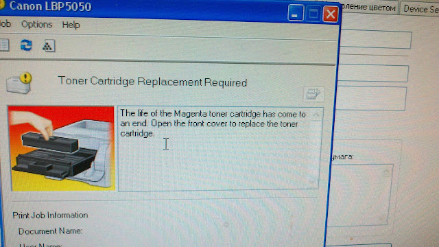
Больше полугода пользуюсь им. Т.к. в семье трое студентов и жена учитель, то, понятное дело, нагружать его приходится по максимуму. За это время два раза заправлял черный картридж, а цветные еще родные. Когда принтер начинает сообщать, что какой-то тонер подходит к концу, то просто меняю чип. Если сразу под рукой чипа нет, то спасает открытие и закрытие крышки с блоком картриджей. Но эту процедуру приходится повторять при каждом выходе на печать. Заправлять картридж носил как только печать становилась неравномерной (в конце страницы или посередине появлялась бледная область печати). За это время ушло где-то 5 пачек бумаги.
Познавательно, но на сколько я знаю, он вообще не должен блокировать печать.
Как обещал отписываюсь. кончился magenta. Заправил отключил контроль чипов. принтер печатает картриджа не просит, калибровку проходит. Версия контроллера 01.03 версия компонента 01.30(данные из страницы конфигурации)
Благодарю, к сожалению версию аппарата, про который я писал узнать уже не могу.
В интернете периодически всплывают вопросы по расхождению цветов и калибровке данного аппарата. И везде проблема начинается в основном с одного – 1) заправил, 2) купили неоригинальную расходку. Советы фактически одни и те же: очистка аппарата от тонерной и бумажной пыли, установка оригинальной расходки, принудительная калибровка аппарата. Но встречаются и исключения.
В моем случае аппарат Canon LBP 5100 у клиента работал на неоригинальных картриджах производства Т2. И вроде бы все было хорошо, пока не случилось это:

Мало того что цвета разбежались, так они еще и потеряли свою насыщенность.
Сразу было принято решение о замене расходников на оригинал и сделана комплексная очистка аппарата. Особенное внимание пришлось уделить блоку лазера. В аппарате он располагается вертикально, и вся пыль оседает на зеркалах и линзах оптики. Особенно было загрязнено самое нижнее зеркало, которое как раз отвечает за красный цвет. Так же были вычищены излучатели и фотоприемники датчиков регистрации цвета, находящиеся также в низу ленты переноса.

Насыщенность цвета вернулась – результат чистой оптики. А вот совмещение цвета осталось на том же уровне. Долговременная принудительная калибровка из драйвера принтера результатов не дала.
По аналогии с аппаратами НР серии 2600, где на калибровку дополнительно влияет функция «отключения контроля чипов» и можно сделать NVRAM Init (грубо говоря сброс на заводские настройки) далее действовать не получится, так как у Canon нет дисплея, нет собственных кнопок меню и нет прошивки на официальном сайте.
Благодаря Танчукову Дмитрию, он же Dimont ® у меня появился дамп прошивки для EEPROM на модель Canon LPB 5000. Но шить родную микросхему 5100 прошивкой от 5000 было боязно, а вдруг чего не так сделаю или спалю микруху. Поэтому в радиодеталях была куплена аналогичная, на которую была залита прошивка. При установке аппарат выдал ошибку Е747 0000, о чем меня предупреждал Тарасов Константин, он же KAT ® — «м/сх не каждого производителя подходят — надо по даташитам подбирать — у некоторых производителей допустимый разброс параметров выходит за рамки, требуемые для принтера. ». Константин советовал вручную править родной дамп, но так как у меня практика по таким вещам отсутствует напрочь (я больше механик), пришлось идти на ход конем – заливать присланную прошивку в родную микросхему.
После установки прошитой микрухи принтер вышел в готовность. В Status Monitor было сообщение – «добавьте бумагу в принтер, или если она там уже есть выставите формат». Формат бумаги выставляется в утилите драйвера принтера. После чего был сделан пробный отпечаток:

Принудительную калибровку проводить не пришлось, хотя Dimont ® в нашей с ним переписке говорил что – «тоже пошло с той, которая с рабочего аппарата не редактированая, правда мне пришлось ещё пяток калибровок сделать чтоб стало идеально, но и сразу было заметно разницу. » При тестировании аппарата результат не изменился.
ВЫВОДЫ:
- прошивка Епром для Canon LBP 5000 и LBP 5100 одинаковые!
- разница в самих производителях микросхем все таки есть!
Саму пошивку можно взять тут
Отдельное спасибо Танчукову Дмитрию, он же Dimont ® и Тарасову Константину, он же KAT ®
Принтер Canon i-SENSYS LBP5050 поверх напечатанного цветного рисунка выдает разноцветные горизонтальные полосы, а нижнюю половину листа еще и подкрашивает в желтый цвет.
Принтер новый, один месяц после покупки, печатал мало, проблема появилась буквально неделю назад, система ХР. Рекомендации англоязычного сервис-центра Canon и руководства провести цикл коррекции вообще не дали ничего.
В черно-белом цвете распечатывает нормально.
Попытки получить помощь в сервисном центре Canon в городе Харькове ничему не привели: люди вымораживаются.
У вас уже есть продукция Canon? Зарегистрируйте свои продукты для доступа к программному обеспечению и обновлениям встроенного ПО, а также подпишитесь на рассылку, чтобы получать персонализированные советы и эксклюзивные предложения
Поддержка
Загружайте драйверы, ПО, встроенное ПО и руководства, а также получите доступ к материалам поддержки для вашего продукта серии i-SENSYS.
Драйверы
Для выполнения подключения некоторых устройств к компьютеру может потребоваться драйвер. На этой вкладке вы найдете соответствующие драйверы для своего устройства или, в случае отсутствия драйверов, описание совместимости устройства с каждой операционной системой.
Полезная информация. Доступ к программному обеспечению, руководствам и другим материалам можно получить с помощью вкладок, расположенных выше.
Операционная система Обнаруженная операционная система
Программное обеспечение
Программное обеспечение загружать необязательно, но оно обеспечивает дополнительные функции и позволяет максимально эффективно пользоваться возможностями устройства. На этой вкладке можно просмотреть и загрузить доступное программное обеспечение для вашего устройства.
Программное обеспечение
Программное обеспечение загружать необязательно, но оно обеспечивает дополнительные функции и позволяет максимально эффективно пользоваться возможностями устройства. На этой вкладке можно просмотреть и загрузить доступное программное обеспечение для вашего устройства.
Руководства пользователя
Руководства для вашего устройства или программного обеспечения перечислены ниже.
Приложения и функции
На этой вкладке можно посмотреть доступные приложения и функции, совместимые с вашим устройством.
Встроенное ПО
Встроенное ПО — это постоянное программное обеспечение, установленное на устройстве и обеспечивающее его корректную работу. Canon может периодически выпускать обновления для этого встроенного ПО, и если обновление доступно, его можно загрузить ниже.
FAQs
На этой вкладке вы найдете ответы на часто задаваемые вопросы и другую полезную информацию, которая поможет вам в решении вопросов и проблем.
Важная информация
На этой вкладке вы найдете подборку часто задаваемых вопросов, которые, на наш взгляд, будут вам интересны.
Коды ошибок
Код ошибки или сообщение об ошибке может появиться на устройстве по различным причинам. С помощью поля поиска можно найти полезную информацию о конкретном коде ошибки, где будут указаны причина ошибки и необходимые действия по ее устранению.
Технические характеристики
Ниже приведены все технические характеристики данного продукта.