
- Manuals
- Brands
- Moeller Manuals
- DC Drives
- DF51
- Hardware and engineering
-
Contents
-
Table of Contents
-
Troubleshooting
-
Bookmarks
Quick Links
Frequency Inverter DF51
Hardware and Engineering
10/05 AWB8230-1541GB
A
T hink future. Switch to green.
Related Manuals for Moeller DF51
Summary of Contents for Moeller DF51
-
Page 1
Frequency Inverter DF51 Hardware and Engineering 10/05 AWB8230-1541GB T hink future. Switch to green. -
Page 2
No part of this manual may be reproduced in any form (printed, photocopy, microfilm or any other process) or processed, duplicated or distributed by means of electronic systems without written permission of Moeller GmbH, Bonn. Subject to alteration without notice. -
Page 3
Warning! Dangerous electrical voltage! Before commencing the installation • Disconnect the power supply of the device. • Devices that are designed for mounting in housings or control cabinets must only be operated and controlled after they have • Ensure that devices cannot be accidentally restarted. been installed and with the housing closed. -
Page 4
• All covers and doors must be kept closed during operation. • To reduce the hazards for people or equipment, the user must include in the machine design measures that restrict the consequences of a malfunction or failure of the drive (increased motor speed or sudden standstill of motor). -
Page 5: Table Of Contents
10/05 AWB8230-1541GB Contents About this manual Abbreviations and symbols About the DF51 series System overview Type code Rating and nameplate Inspecting the items supplied Layout of the DF51 Features of the frequency inverters Selection criteria Intended use From DF5 to DF51…
-
Page 6
– Quick parameter selection – Menu overview – Setting the display parameters – Examples for changing parameters Using the keypad – Controlling the DF51 with keypad DEX-KEY-6 Setting parameters Motor data Motor control – U/f characteristic – Limit and target values –… -
Page 7
10/05 AWB8230-1541GB Contents Monitoring functions – Limiting motor current – Suppressing overcurrent stopping – Overload signal (OL) – Thermal overload – Thermistor (PTC) – Supply voltage (POWER) – Fault messages – Fault register – Fault signal (AL) – External fault signal (EXT) –… -
Page 8
Maintenance and inspection General Device fans Appendix Technical data – General technical data of the DF51 – Specific technical data of the DF51-322 – Specific technical data of the DF51-320 – Specific technical data of the DF51-340 Weights and dimensions Optional modules –… -
Page 9: Abbreviations And Symbols
It contains special information which is required for engineering, of engineering fundamentals and that you are familiar with installation and operation of the DF51 frequency inverters. The electrical systems and the applicable principles and are able to features, parameters and functions are described in detail and read, interpret and apply the information contained in technical illustrated with examples of the most important applications.
-
Page 10
10/05 AWB8230-1541GB… -
Page 11: System Overview
10/05 AWB8230-1541GB 1 About the DF51 series System overview POW ER ALA RM RU N PR G PO W ER AL AR M PR G EN TE R RU N PR G PR G EN TE R PO W ER…
-
Page 12: Type Code
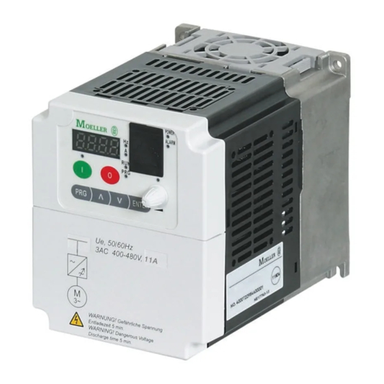
10/05 AWB8230-1541GB About the DF51 series Type code Rating and nameplate Type codes and part numbers of the DF51 series frequency The electrical connection ratings are printed on the terminal inverters: shroud. DF51 — x x x — yyy Ue, 50/60Hz…
-
Page 13
10/05 AWB8230-1541GB Rating and nameplate The DF51’s rating is recorded on the nameplate on the unit’s side. POW ER ALA RM RU N PR G PR G EN TE R Type : DF51-322-025 Input : 1/3AC 230V, 3.1A, 2.0A (Ue : 180…264g0%, 50/60Hz Output : 3AC 0…Ue, 1.4A, 0…400Hz… -
Page 14: Inspecting The Items Supplied
• one DF51 frequency inverter Inspecting the items supplied • installation instructions AWA8230-2146, The DF51 frequency inverters have been carefully packaged and • a CD with: prepared for delivery. The devices must be transported only in their – this manual in PDF format in English and other languages original packaging with a suitable transport system (see weight –…
-
Page 15: Layout Of The Df51
PR G EN TER Figure 6: Overview of the DF51 a LCD keypad with interface g Heat sink b Device fan (DF51…1K5 to …7K5 only) h Earth connection (PE) c RJ 45 communication interface (Modbus) i Power terminals d Microswitch…
-
Page 16: Features Of The Frequency Inverters
10/05 AWB8230-1541GB About the DF51 series Features of the frequency inverters The DF51 frequency inverters convert the voltage and frequency of an existing three-phase supply to a DC voltage and use this voltage to generate a three-phase supply with adjustable voltage and frequency.
-
Page 17: Intended Use
EN 60204. The user of the equipment is responsible for ensuring that the machine use complies with the relevant EU Directives. The CE markings on the DF51 frequency inverter confirm that, when used in a typical drive configuration, the apparatus complies…
-
Page 18: From Df5 To Df51
Service and warranty The frequency inverter DF51 has been developed from the proven In the unlikely event that you have a problem with your Moeller DF5 series. It shares its basic functions, terminal markings, menu frequency inverter, please contact your local sales office.
-
Page 19: Features Of The Df51
10/05 AWB8230-1541GB 2 Engineering This section describes the „Features of the DF51“ and the • Connection to power supply requirements and standards relating to the following issues: • EMC Directive for PDS drive systems Features of the DF51 General Standards EN 50178, IEC 61800-3, EN 61800-3 incl.
-
Page 20
10/05 AWB8230-1541GB Engineering Frequency resolution 0.1 at digital reference values/maximum frequency/1000 at analog reference values Frequency error limit at 20 °C g 10 K g0.01 % of maximum frequency at digital reference values, g0.1 % of maximum frequency at analog reference values Permissible overcurrent 150 % for 60 s, every 600 s Torque during start… -
Page 21
10/05 AWB8230-1541GB Features of the DF51 The illustration below shows an overview of the connections. 3 h 400 V, 50/60 Hz I > I > I > K14 K12 K11 DC+ DC- ˜ Figure 9: Power input connection overview a Network configuration, mains voltage, mains frequency g Motor filter interaction with p.f. -
Page 22: Connection To Power Supply
The ratings of the DF51 frequency inverters cover European and American standard voltages: • 230 V, 50 Hz (EU) and 240 V, 60 Hz (USA) for DF51-320 and DF51-322, • 400 V, 50 Hz (EU) and 460 V, 60 Hz (USA) for DF51-340 The permitted line voltage range is: •…
-
Page 23: Residual Current Circuit-Breakers
The mains contactor is connected to the mains side input cables breakers (RCCBs; also called earth-leakage circuit breakers or L1, L2, L3 or L and N (depending on its type). and allows the DF51 ELCBs) must be used. For the protection of persons, systems with…
-
Page 24: Line Filters
Corresponds with CISPR 11 Class B CISPR 11 Class A Power supply from Group 1 and the public mains, Figure 10: DF51 and radio interference filter in a sealed enclosure Warning which also supplies households. K1: RFI filter T1: Frequency inverter…
-
Page 25: Emc Interference Class
87 Hz 1) Observe the motor’s limit values! Connecting motors in parallel The DF51 frequency inverters allow parallel operation of several motors in U/f control mode: • U/f control: several motors with the same or different ratings. The sum of all motor currents must be less than the frequency inverter’s rated current.
-
Page 26
(paragraph “Mains 5.15 A contactors”, page 210). These mains contactors are DF51-340-2K2, rated current 5.5 A. designed only for the frequency inverter’s mains (primary) currents. If contactors of this size are used in the motor DEX-LM3-008 motor reactor circuit, the contacts could weld. -
Page 27
10/05 AWB8230-1541GB Motor and circuit type When an individual motor is switched into the frequency inverter’s Motor chokes, du/dt filters, sinusoidal filters output, it behaves as if is connected directly to the electrical mains. Motor reactors compensate for capacitive currents with long When you select a frequency inverter, take into account the motor cables and with grouped drives (multiple connection of highest possible inrush current and use a motor reactor or a… -
Page 28: Braking
10/05 AWB8230-1541GB Engineering Bypass operation Braking If you want to have the option of operating the motor with the Motor braking shortens unwanted deceleration distances and frequency inverter or directly from the mains supply, the incoming times. Braking can be mechanical or electrical. supplies must be mechanically interlocked: Mechanical brakes act directly on the motor’s rotating shaft and Caution!
-
Page 29: Pid Control
10/05 AWB8230-1541GB Braking PID control In closed-loop control systems – in contrast to open-loop control – value to the reference value in as short a time as possible, so that the actual value of the controlled variable is automatically fed back the difference between reference value and actual value (the to the controller.
-
Page 30
10/05 AWB8230-1541GB Engineering D: differential component Differential control increases the value of K and therefore the rate of change while reducing system deviation. If the reference values is static, it does not issue a control signal. D-control is therefore used only in combination with P- or PI control. Figure 19: D-control PID control represents an “ideal”… -
Page 31: Fitting The Df51
10/05 AWB8230-1541GB 3 Installation The DF51 frequency inverters are designed for installation in a Fitting dimensions control panel or a metal enclosure (for example to IP 54). A free space of at least 100 mm is required above and below the device to allow air circulation for cooling.
-
Page 32
10/05 AWB8230-1541GB Installation When you mount a DF51 in an individual enclosure, for example Minimum free space for installation of DF51 inside an to increase its degree of protection, the distances to the enclosure enclosure (separate mounting). walls must be at least as shown below. -
Page 33: Mounting The Df51
10/05 AWB8230-1541GB EMC compliance Mounting the DF51 Mount the DF51 frequency inverter as shown in Fig.23 and tighten the screws to the following torque values (a table 3): POW ER ALA RM RU N PR G PR G EN TER…
-
Page 34: Emc Measures In The Control Panel
• the protective conductor must have a cross-section f 10 mm • the protective conductor is monitored to ensure continuity, or • an additional protective conductor is also installed. For DF51 frequency inverters, use the assigned DE51-LZ… filters.
-
Page 35: Earthing
10/05 AWB8230-1541GB EMC compliance POWER ALARM ENTER W2 U2 V2 U1 V1 W1 Figure 27: EMC-compliant setup a Large-area connection of all metallic control panel components. b Mounting surfaces of frequency inverter, RFI filter and cable screen must be free from paint. c Connect screens of cables at frequency inverter’s output with earth potential (PES) across large surface area.
-
Page 36: Cable Routing
100 Figure 29: Crossover of signal and power cables Example: DF51 a Power cable: L1, L2, L3 or L and N, PE, U, V, W, L+, DC+, DC–, RB b Control and signal cables: H, O, OI, L, AM, 1 to 5 and 12, CM2, P24…
-
Page 37: Screening
10/05 AWB8230-1541GB EMC compliance Screening Screening control and signal cables To increase operational reliability, screen analog and Unscreened cables behave like antennae, i.e. they act as digital control signal cables and lay them well away from transmitters and receivers. To ensure EMC-compliant connection, screen all interference-emitting cables (frequency inverter/motor the power cables.
-
Page 38: Electrical Connection
To connect the power supply, motor cables and control signal cables, take off the terminal shroud. Front cover The electrical connections of the DF51 are made through plug-in control signal terminals and combination terminal screws in the power section, which is normally covered by a terminal shroud.
-
Page 39
Then pull the terminal shroud downwards Complete the following steps with the tools stated and without the use of force. On devices DF51-…-5K5 and DF51-…-7K5, the terminal shroud hinges downwards. and can be removed in its lowered position. To open the terminal shroud: Figure 35: Opening the terminal shroud Pull out the cable retainer. -
Page 40
10/05 AWB8230-1541GB Installation Arrangement of the power terminals The arrangement of power terminals depends on the size of the power section. DF51-322-025 DF51-322-055 DF51-322-075 DF51-322-2K2 DF51-322-037 DF51-322-1K1 DF51-320-4K0 DC– DC– L/L1 N/L3 L/L1 N/L3 DF51-340-037 DF51-340-2K2 DF51-340-5K5 DF51-340-7K5 DF51-340-075 DF51-340-3K0… -
Page 41
Select a frequency inverter that is suitable for the available supply voltage (a section “Technical data”, page 189): • DF51-320: Three-phase 230 V (180 to 264 V g 0 %) • DF51-322: Single- or three-phase 230 V (180 to 264 V g 0 %) •… -
Page 42
Table 5: Tightening torques and cable cross-sections for the power terminals (combination and terminal screws) L, L1, L2, L3, N, L+, DC+, DC–, U, V, W, ft-lbs DF51-322-025 6 – 8 M3.5 DF51-322-037 M4 (PE) DF51-322-055 DF51-340-037 8 –… -
Page 43
Connect the mains voltage or the RFI filter outputs to the following terminals: F1, Q1 = UL, fuse sizes L1 L2 L3 DF51-322… DF51-320… 1 h 230 V, 50/60 Hz 3 h 230 V, 50/60 Hz DF51-340… 3 h 400 V, 50/60 Hz DC+ DC–… -
Page 44
– 50 A DF51-322-025 10 A 10 A DF51-322-037 In frequency inverter operation with the DF51, you can reverse the DF51-322-055 direction of rotation of the motor shaft by: DF51-322-075 16 A 16 A • exchanging two of the phases connected to the motor;… -
Page 45: Connecting A Signalling Relay
10/05 AWB8230-1541GB Electrical connection Connecting a signalling relay Table 7: Description of the signalling relay terminals Terminal Description The signalling relay consists of a floating contact (changeover designation switch). The contacts are connected to terminals K11, K12 and K14. Default settings: The illustration to the right indicates the position of the signalling •…
-
Page 46: Connecting The Control Signal Terminals
10/05 AWB8230-1541GB Installation Connecting the control signal terminals The illustration to the right shows the positions of the individual control signal terminals. The control signal terminals are arranged in a single row. Wire the control signal terminals to suit their application. For instructions for changing the function of the control signal terminals, see paragraph “Control signal terminal overview (input)”, page 74.
-
Page 47
10/05 AWB8230-1541GB Electrical connection Function of the control signal terminals Table 10: Function of the control signal terminals Function Level Technical data, description Common reference – Reference potential for the internal voltage sources potential P24 and H Digital input HIGH: 17.4 … 27 V H Reset PNP logic, configurable, R >… -
Page 48
10/05 AWB8230-1541GB Installation – Figure 44: Control signal terminal strip (part 1) Inputs 1 to 5 all have the same function and mode of operation You can configure the actuation of inputs 1 to 5 for special control except for terminal 5, which can also be configured as thermistor circuits and national circuit types Table 11 shows the various input. -
Page 49
10/05 AWB8230-1541GB Electrical connection Table 11: Actuation of inputs 1 to 5 Circuit example SR/SK switch Description • Operation with internal control voltage • Standard circuit +24 V • Operation with external control voltage +24 V) • Standard circuit +24 V •… -
Page 50
10/05 AWB8230-1541GB Installation Circuit example SR/SK switch Description Operation with internal control voltage +24 V • Operation with external control voltage +24 V) • Reference point terminal L +24 V +24 V a If reference point L is connected with the 0 V potential of the external voltage source, the external 24 V potential should be decoupled through a diode. -
Page 51
10/05 AWB8230-1541GB Electrical connection – Figure 46: Control signal terminal strip (part 2) Terminal H outputs +10 V (max. 10 mA) to provide the setpoint All analog inputs and outputs use terminal L as reference voltage for supplying an external potentiometer. Reference point potential and are therefore also connected to the is terminal L. -
Page 52
10/05 AWB8230-1541GB Installation Terminal AM supplies an analog reference signal from 0 to +10 V If a relay is connected to one of the digital outputs 11 or 12, (default = 0 to 50 Hz). The reference potential is terminal L. The connect a freewheel diode in parallel to the relay to prevent analog signal can be configured with parameters PNU B080, C028 destruction of the digital outputs through the self-induced e.m.f. -
Page 53: Using The Df51
10/05 AWB8230-1541GB 4 Using the DF51 This section describes how to take the DF51 frequency inverter into operation and what you should observe during its operation. Operational warnings Warning! When the supply voltage for the frequency inverter is Danger! applied while the start signal is active, the motor will If the supply voltage recovers after an intermittent start immediately.
-
Page 54: Block Diagram
RJ 45 ModBus DC– – K12 K14 * PNU C005 = 19 (PTC) Figure 50: Block diagram, DF51 Power terminals Digital input Analog input, 4 to 20 mA L, L1, L2, L3, N Supply (mains) voltage Digital input Analog output, 0 to 10 V…
-
Page 55: Initial Starting
LED. • Motor ratings: voltage, current and frequency of a normal, surface-cooled, four-pole three-phase asynchronous motor. • Maximum speed: 1500 r.p.m. at 50 Hz (DF51-320: 1800 r.p.m. at 60 Hz). • Acceleration and deceleration time = 10 seconds.
-
Page 56: Standard Operation, Actuation With Default Settings
10/05 AWB8230-1541GB Using the DF51 • control the motor speed (0 to 50 Hz, or 0 to 60 Hz for DF51-320-…) with potentiometer R1 through the analog POWER reference value input. ALARM Switches and potentiometer are not included as standard with the frequency inverter.
-
Page 57
10/05 AWB8230-1541GB Initial starting Table 15: Function of control signal terminals (inputs a fig. 53) Function Level Technical data, description Common reference – Reference potential for the internal voltage sources potential P24 and H HIGH: 17.4 … 27 V H Digital input Reset PNP logic, configurable, R… -
Page 58: Default Functions Of Output Terminals
10/05 AWB8230-1541GB Using the DF51 Default functions of output terminals By default, the control signal outputs have the functions described below. +24 V 0…10 V = 0…50 Hz Figure 54: Active outputs with default settings a Frequency indication, 0 to 10 V = 0 to 50 Hz…
-
Page 59: Keypad
10/05 AWB8230-1541GB Keypad Keypad Number Name Explanation The illustration below shows the elements of the DF51’s built-in PRG key Programming mode. Selection and keypad. activation of the specified parameter (PNU) Start key and Motor start with the selected direction; disabled by default.
-
Page 60: Quick Parameter Selection
10/05 AWB8230-1541GB Using the DF51 Quick parameter selection To change to the second, third and fourth digit of the display, press To activate quick selection mode, press both arrow keys Í and Ú the Enter key each time. The active digit flashes in each case. To change the value of the active digit (0 to 9), use the arrow keys (Í…
-
Page 61: Setting The Display Parameters
Total time in hours in which DF51 is in RUN operation. counter d017 Indication – mains On time Total time in hour in which DF51 was live (mains, internal DC link) (Power display). d080 Indication – total number of Total number of detected fault signals (E…).
-
Page 62: Examples For Changing Parameters
10/05 AWB8230-1541GB Using the DF51 Examples for changing parameters The value 0.0 appears again in the display and the Hz LED lights up. You have reduced the acceleration time from 10 s to 5 s. The following example assumes the default settings.
-
Page 63
10/05 AWB8230-1541GB Keypad ENTER Figure 61: Change maximum frequency (example with default setting) a Display value 0.0 Hz b Parameter to the displayed value a… -
Page 64
10/05 AWB8230-1541GB Using the DF51 Here is a short overview of the most important parameters. This overview is supplied on a self-adhesive foil with every device and when necessary can be affixed, for example, to the inside of the terminal shroud. -
Page 65: Using The Keypad
10/05 AWB8230-1541GB Using the keypad Using the keypad Controlling the DF51 with keypad DEX-KEY-6 The following example compares the input of control signals (FWD = Start/Stop) and the frequency reference value (R1) using keypad DEX-KEY-and the standard connection (a figure 63).
-
Page 66
Micro switch TM/PRG must be in the PRG position. the potentiometer and the start key on the keypad. The assigned green LED lights up to indicate activation. With these parameters the DF51 frequency inverter can be operated through the control signal terminals without commands. POWER… -
Page 67: Setting Parameters
10/05 AWB8230-1541GB 5 Setting parameters You can adapt the DF51 to your specific applications. To do this, you need to change the frequency inverter’s parameters with the built-in keypad, the optional keypads DEX-KEY-… or the Drives- Soft configuration software. Table 20: Devices for changing parameter settings…
-
Page 68: Motor Data
0.4 = 0.37 kW. The connected motor rating should be only one order H203 [kW]/{HP} at 2.2; 3.0; 4.0; lower (for example 0.25 kW connected to a DF51-…-037). If the rated voltage 5.5; 7.5; 11.0 connected load is too small, the motor may suffer thermal overload.
-
Page 69: Motor Control
Name b031 Value Function = 10 A044 – – By default, the DF51 uses a linear U/f characteristic characteristic (constant torque curve) to accelerate and brake the motor. a Linear b Quadratic Constant torque curve Reduced torque curve With a linear U/f characteristic the ratio of output voltage to •…
-
Page 70: Limit And Target Values
30 – 400 Hz (fmax) {60} A204 1) 60 at DF51-320-… End frequency If a constant-voltage frequency range exists beyond the transition frequency set with PNU A003 define this range with PNU A004. The maximum frequency must not be smaller than the base frequency.
-
Page 71: Automatic Voltage Regulation (Avr)
Output voltage – – 200, 215, 220, • 200 V range:DF51-32…-…: 200, 215, 220, 230, 240 230/4 (AVR motor 230, 240, 380, • 400 V range: DF51-340-…: 380, 400, 415, 440, 460, 480 rated voltage) 400, 415, 440, 460, 480…
-
Page 72: Output Voltage And Voltage Boost
10/05 AWB8230-1541GB Setting parameters Output voltage and voltage boost If the mass inertia moment or static friction of the connected load is high, the output voltage must be increased (boosted) beyond the normal U/f component at low output frequencies. This compensates for the voltage drop in the motor windings and can be up to half of the motor’s nominal voltage.
-
Page 73: Reference And Control Signal Inputs
10/05 AWB8230-1541GB Motor control Reference and control signal inputs Figure 72: Microswitches By default (PNU A001 = 01 and A002 = 01), the position of Reference value and control signal inputs depend on microswitch TM/PRG is ignored for the purpose of reference value PNU A001 and A002 and the position of microswitches and control signal input.
-
Page 74
10/05 AWB8230-1541GB Setting parameters POWER ALARM ENTER A001 F002 F003 F-COM Modbus F001 START STOP FWD/REV 1 P24 A002 OPE-Mode Figure 73: Block diagram, reference value/control signal input Name b031 Value Function = 10 A001 Reference – – The setting range is limited by PNU b082 (raised starting frequency) and value source A004 (maximum frequency). -
Page 75
10/05 AWB8230-1541GB Motor control Additional control signals allow the reference source selected with PNU A001 (F-COM) to be temporarily exceeded. Example: When a fixed frequency (CF1 to CF4) is activated, the analog reference value of control signal terminals O or OI is overwritten. Priority Reference input source Description… -
Page 76: Basic Parameters
10/05 AWB8230-1541GB Setting parameters Basic parameters Input/indication of reference frequency PNU F01 indicates the current reference frequency or the current fixed frequency. You can change the frequencies with the arrow keys and save the settings as defined with PNU A01 and the fixed frequency stages CF1 to CF4 (digital inputs) (a section “Fixed frequencies”, page 97).
-
Page 77
10/05 AWB8230-1541GB Motor control Second acceleration and deceleration time F002 F003 F-COM F001 START STOP FWD/REV F004 Figure 75: Acceleration/deceleration ramps Acceleration time 1 Acceleration time 1 defines the time in which the frequency inverter reaches its maximum frequency after a start signal is issued. -
Page 78: Control Signal Terminal Overview (Input)
10/05 AWB8230-1541GB Setting parameters Acceleration and deceleration characteristic Name b031 Value Function = 10 A097 Acceleration – – Here, you can set a linear or an S-curve acceleration characteristic for motor acceleration time, (first and second time ramp): characteristic linear S curve A098 Deceleration…
-
Page 79
10/05 AWB8230-1541GB Motor control Name Value Function Description Programmable fixed Example: Four fixed frequencies frequencies 1 to 4, bit 0 (LSB) to bit 3 (MSB) = 0 to f For four fixed frequency stages (three programmable fixed frequencies and a setpoint value), two fixed frequency inputs (3 = CF1 and 4 = CF2) are required (2 = 4). -
Page 80
10/05 AWB8230-1541GB Setting parameters Name Value Function Description PID control enabled Closing causes temporary disabling of PID control (PNU A071 = 01). PIDC Reset I-component of Closing causes disabling and resetting of the I-component. PID control Acceleration (motor When input UP is switched on, the motor accelerates (available only if you have specified the potentiometer) reference frequency with PNU F001 or A020). -
Page 81: Start Signal Input
(+24 V). input, the frequency in phase sequence U-V-W is applied at the DF51’s output. If connected accordingly, the motor then starts up Caution! in a clockwise direction. When the input is deactivated, the motor If an EEPROM error occurs, (fault message E08), all is decelerated.
-
Page 82
10/05 AWB8230-1541GB Setting parameters Table 23: Function of the digital inputs Value Function Description a page Value Function Description a page Deceleration (motor potentiometer) Start/stop clockwise Reset frequency (motor Start/stop anticlockwise potentiometer) Binary input 1 (LSB) (fixed Keypad frequency 1) Add frequency offset Binary input 2 (fixed frequency 2) -
Page 83: Controller Inhibit And Coasting (Free Run Stop — Frs)
10/05 AWB8230-1541GB Motor control Controller inhibit and coasting (free run stop – FRS) Use PNU b088 to specify whether the motor is to restart at 0 Hz after the FRS input has been deactivated, or if synchronization If you activate the digital input configured as FRS, the motor is to the current motor speed should take place after a waiting switched off and coasts to a stop (for example if an Emergency- time specified under PNU b003.
-
Page 84: Three-Wire Control (Sta — Stp — F/R)
10/05 AWB8230-1541GB Setting parameters Three-wire control (STA – STP – F/R) In PNU A002 enter the value 01 (start signal through digital inputs). Three-wire control is a common control method for machines: Two In PNU A020 enter the reference frequency. inputs are used for start and stop pulses and a third for selecting the direction of rotation.
-
Page 85: Control Signal Terminal Modus (F-Tm) And Keypad (Ope)
10/05 AWB8230-1541GB Motor control Control signal terminal modus (F-TM) and keypad (OPE) PNU A001 = 00 The keypad’s potentiometer as reference frequency source. If you apply value 51 (F-TM) to one of digital inputs 1 to 5 under PNU C001 to C005, the control signal terminals are used as source PNU A002 = 02 The keypad’s Start key as start signal source.
-
Page 86
10/05 AWB8230-1541GB Setting parameters POWER ALARM F-TM POW ER ALAR M RU N ENTER PR G STOP PR G EN TER START STOP F-TM Figure 82: Selecting the control signal source a Start/Stop through digital input 1 (FWD) with active digital input 3 (F-TM, Force Terminal Mode). b Start/Stop through keypad DEX-KEY-…… -
Page 87: Second Parameter Set (Set)
10/05 AWB8230-1541GB Motor control Second parameter set (SET) The functions of the second parameter set are listed in Table 28, page 85. With function SET you can activate the second parameter set through one of digital inputs 1 to 5. Configure one of the digital inputs 1 to 5 as SET by entering the value 08 under the corresponding PNU (C001 to C005).
-
Page 88
10/05 AWB8230-1541GB Setting parameters F003 A093 Digital input 4 C005 = 09 (2CH) FWD/REV When FWD (digital input 1) is deactivated, the drive is slowed with the deceleration ramp specified in PNU F003. To change to another deceleration ramp (PNU A093), activate 2CH (second time ramp) (a section “Changing over time ramps”, page 93). F003 A293 Digital input 3… -
Page 89
10/05 AWB8230-1541GB Motor control Notes about changing settings in the second parameter Functions FRS (11), EXT (12), RST (18), PTC (19) and PID (23) must be assigned to the same digital inputs 1 to 5 Functions SET and SP-SET can not be assigned at the (PNU C001 to C005) in the first and second parameter set same time for digital inputs 1 to 6. -
Page 90: Specifying Reference Frequencies
10/05 AWB8230-1541GB Setting parameters Description of the function Parameter number (PNU) Default Second parameter set (STOP) SET (STOP) SP-SET (RUN) Thermal overload, characteristic (torque curve) b013 b213 – Motor current limitation – function b021 b221 – Tripping current for motor current limitation b022 b222 –…
-
Page 91
10/05 AWB8230-1541GB Motor control POWER ALARM ENTER F001 A001 F-COM Modbus Figure 85: Frequency reference value definition Name b031 Value Function = 10 A001 Reference – – The setting range is limited by PNU b082 (raised starting frequency) and value source A004 (maximum frequency). -
Page 92
10/05 AWB8230-1541GB Setting parameters Analog input the setpoint value. If none of the digital inputs are configured as With PNU A001 select the reference frequency source. By default AT, both voltage input O and current input OI are active. If the (PNU A001 = 01), the voltage of 0 to 10 V H at terminal O or the current and voltage signals are applied at the same time, the incoming current of 4 to 20 mA H at terminal OI is interpreted as… -
Page 93
10/05 AWB8230-1541GB Motor control Defining reference value through voltage Analog input O [Hz] The external reference voltage signal can be specifically matched A004 with parameters PNU A011 to A016, which are described below. You can assign the output frequency to a user-definable voltage A012 reference value range. -
Page 94
10/05 AWB8230-1541GB Setting parameters Reference current Analog input OI [Hz] The external reference current signal can be specifically matched A004 with parameters PNU A101 to A106, which are described below. You can assign the output frequency to a user-definable current A102 reference value range. -
Page 95
10/05 AWB8230-1541GB Motor control Reference value control (AT) When the digital input which has been configured as AT is active, With the AT command you can enable manual selection of analog the reference value is defined by the current flow (4 to 20 mA) at reference sources. -
Page 96
10/05 AWB8230-1541GB Setting parameters Potentiometer (keypad) To define the potentiometer’s function, use the following Reference value input through the built-in potentiometer. parameters: [Hz] A004 A152 POW ER ALA RM RU N PR G A155 = 00 PR G EN TE R A151 A155 = 01 100 %… -
Page 97: Changing Over Time Ramps
10/05 AWB8230-1541GB Motor control Changing over time ramps F002 A092 During operation, you can change over from the time ramps set under PNU F002 and F003 to those programmed under PNU A092 and A093. This can be done either by applying an external signal to digital input 2CH at any time or when the frequencies configured under PNU A095 and A096 are reached.
-
Page 98
10/05 AWB8230-1541GB Setting parameters Name b031 Value Function = 10 A096 Deceleration – – 0.0 – 400 Hz Here, set a frequency at which the changeover from the first to the time, frequency second deceleration time is to take place. A296 for changeover from ramp time… -
Page 99: Minimum And Maximum Operating Frequency
10/05 AWB8230-1541GB Motor control Minimum and maximum operating frequency With PNU A061 and A062 you can limit the frequency range [Hz] defined with PNU b082 (starting frequency) and PNU A004 A004 (maximum frequency) (a fig. 95). As soon as the frequency inverter receives a start signal, it outputs the frequency set with PNU A062;…
-
Page 100: Suppressing Frequency Ranges
10/05 AWB8230-1541GB Setting parameters Suppressing frequency ranges To prevent resonances occurring in the drive system, you can, in [Hz] addition, program three frequency jumps under PNU A063 to A068. A067 In the example (a fig. 96), the first frequency jump (PNU A063) A065 is at 15 Hz, the second (PNU A065) at 25 Hz and the third (PNU A067) at 35 Hz.
-
Page 101: Fixed Frequencies
10/05 AWB8230-1541GB Motor control Fixed frequencies Through digital input configured as CF1 to CF4 you can select up to 16 user-definable fixed frequencies (including a reference frequency) (a table 29). The fixed frequencies have a higher priority than all other reference values and can be accessed at any time through inputs CF1 to CF4 without needing to be enabled separately.
-
Page 102
Press the ENTER key to save the value in PNU A023. If you have configured further digital inputs with CF3 and CF4 (PNU C001 to C005), you can enter up to 15 fixed frequencies. The DF51 saves these values in PNU A021 to A035 (a table 29). -
Page 103: Motor Potentiometer
10/05 AWB8230-1541GB Motor control Motor potentiometer With the UP and DWN (down) signals, you can enter the reference FWD/REV frequency using an electronic motor potentiometer. Figure 99: Control using electronic motor potentiometer Figure 100:Function chart for UP/DWN (acceleration/deceleration – Because the terminal functions UP and DWN can be used only motor potentiometer) when the frequency setpoint has been specified with PNU F001 or A020, you need to make sure that PNU A001 contains the…
-
Page 104
10/05 AWB8230-1541GB Setting parameters Name b031 Value Function = 10 A001 Reference – – The setting range is limited by PNU b082 (raised starting frequency) and value source A004 (maximum frequency). selection • Potentiometer (keypad) • Frequency [Hz] • Process variable [%] with active PID control (PNU A071 = 1) Analog input: Control signal terminals O and OI Set value (PNU F001) of the keypad (arrow keys Í/Ú). -
Page 105: Jog Mode
10/05 AWB8230-1541GB Motor control Jog mode To do this, enter the value 02 in PNU A002. Set microswitch TM/PRG to its PRG position. Jog mode is used, for example, to set up a machine in manual Activate the digital input configured as JOG. control mode.
-
Page 106: Actual Value And Status Signals
10/05 AWB8230-1541GB Setting parameters Control signal terminal overview (output) Actual value and status signals The table below provides an overview of the output control signal This section describes how to assign various actual values and terminals and a brief description of the functions which you can status signals to the control signal terminals.
-
Page 107
10/05 AWB8230-1541GB Actual value and status signals Name Value Name Description Result of logic link LOG (Logical Output) shows the result of PNU C143 (High, Low) of (PNU C143) the logic function (AND, OR, XOR). Fault/Warning: ODc (Overload Disconnect Detect) monitors the serial RS 485 Interrupted interface (Modbus) in connection with optional field bus interface communication through… -
Page 108: Analog Output (Am)
10/05 AWB8230-1541GB Setting parameters Analog output (AM) b080 = 200 % 10 V b080 = 100 % – 0 – 10 V 1 mA b080 = 50 % Figure 103:Analog output AM The AM terminal provides the output frequency or the motor current as voltage signal (0 to +10 V).
-
Page 109: Parameterizable Digital Outputs
10/05 AWB8230-1541GB Actual value and status signals Parameterizable digital outputs Table 32: Functions of the digital outputs Value Function Description a page RUN: In operation FA1: Frequency reference value reached FA2: Frequency signal – output frequency exceeds value in PNU C042 (during acceleration ramp) or PNU C043 (during deceleration ramp)
-
Page 110
10/05 AWB8230-1541GB Setting parameters Configurable digital outputs 11 and 12 are by default configured Response time of outputs as N/O contacts. When an assigned function activates the output, You can set the response time of digital outputs 11 and 12 terminal CM2 is connected with terminal 11 or 12. -
Page 111: Signalling Relay K1 (Terminals K11, K12, K14)
Table 34: Default setting of the signalling relay Default setting of the signalling relay Reconfigured signalling relay terminals (PNU 036 = 00) Fault or DF51 switched off Run signal Fault message Run signal or DF51 switched off K11 K14 K11 K14 K11 K14 K11 K14 Voltage…
-
Page 112
10/05 AWB8230-1541GB Setting parameters Table 35: Functions of the signalling relay Name b031 Value Function = 10 C026 Relay K1 – – – RUN: In operation signal FA1: Frequency reference value reached FA2: Frequency signal – output frequency exceeds value in PNU C042 (during acceleration ramp) or PNU C043 (during deceleration ramp) OL: Overload warning –… -
Page 113: Run Signal
10/05 AWB8230-1541GB Actual value and status signals RUN signal The RUN signal is issued when an enable signal (FWD/REV) is applied. With the set deceleration ramp, the RUN signal remains 24 V active until the output frequency has reached 0 Hz. 50 mA FWD/REV Figure 110:Digital output 12 configured as RUN (Run signal)
-
Page 114: Frequency Value Signal (Fa1/Fa2)
10/05 AWB8230-1541GB Setting parameters Frequency value signal (FA1/FA2) Signal FA1 (FA = Frequency Adjustment) is issued when the output frequency is the same as the reference frequency. C042 C043 24 V 50 mA Figure 111:Digital output 11 configured as FA1 (frequency reached) 60 ms To ensure system hysteresis, signals FA1 and FA2 are activated each time the actual frequency is 0.5 Hz short of the setpoint or…
-
Page 115
10/05 AWB8230-1541GB Actual value and status signals Name b031 Value Function = 10 C042 Output – 0 – 400 Hz The digital output (11 or 12) PNU C042 function – configured as FA2 becomes signalling active when the frequency PNU C043 threshold for entered here is exceeded frequency… -
Page 116: Monitoring Functions
10/05 AWB8230-1541GB Setting parameters Monitoring functions The functions described here are used to monitor the power section for overload and to protect the connected motor. 0 – 10 V Limiting motor current = 10 – 150 % I If the output current (= motor current, I ) exceeds the value set Figure 115:Connection of potentiometer to the external overload with PNU b022 (b222), the output frequency (rotating field…
-
Page 117: Suppressing Overcurrent Stopping
10/05 AWB8230-1541GB Monitoring functions Suppressing overcurrent stopping With PNU b140 you can access the inverter directly when a sudden overcurrent is detected. PNU b140 = 01 sets an automatic In applications with highly dynamic drives and rapid load changes, reduction of the pulse frequency and a delay of the output values motor current limitation (PNU b020 to b028) can not prevent (voltage, frequency) until the current is within the control range sudden overcurrents.
-
Page 118: Overload Signal (Ol)
10/05 AWB8230-1541GB Setting parameters Overload signal (OL) The overload signal (OL) is output when the current value set with PNU C041 is exceeded. 24 V 50 mA C041 Figure 118:Digital output 11 configured as an OL (overload signal) Figure 117:Function chart for OL (overload signal) : Motor current To configure digital output 11 or 12 or signalling relay K1 as OL, define the current under PNU C041 at which, when exceeded,…
-
Page 119: Thermal Overload
Thermal overload In PNU b013, set the overload protection according to the applicable motor load. Using an electronically simulated bimetallic strip, the DF51 frequency inverters can provide thermal monitoring of the connected motor. With PNU b012, match the electronic motor protection to the motor’s rated current.
-
Page 120: Thermistor (Ptc)
If digital input 5 is configured as PTC, but no thermistor is connected, fault message E 35 is displayed. If the DF51 has issued fault signal E 35 and you want to reconfigure digital input 5, which is configured as PTC, do the following: Connect a link between digital input 5 and terminal L.
-
Page 121: Supply Voltage (Power)
(+10 V) and the voltage for the control The DF51 frequency inverters can be supplied with AC voltage signal terminals (+24 V). Charging of the internal DC link and (50/60 Hz mains voltage) or DC voltage.
-
Page 122
10/05 AWB8230-1541GB Setting parameters Name b031 Value Function = 10 b004 POWER, fault – OFF, disabled. No fault message is issued. signal on ON, enabled. In the event of an intermittent power supply failure or intermittent undervoltage, the frequency inverter goes into fault status (E 09). supply voltage failure or undervoltage… -
Page 123: Fault Messages
The connected motor then coasts to a halt and the fault signal is indicated by the red ALARM LED. The display shows an error code (E…). The DF51 remains inhibited until the fault message is acknowledged. To…
-
Page 124: Fault Register
PNU d082 last but one, etc. When a new fault occurs, it is saved to PNU d081 and all older faults are moved on by one The frequency inverters DF51 have a fault register. to which the PNU (PNU d081 a d082, PNU d082 a d083, etc.) three most recent fault messages are saved.
-
Page 125: Fault Signal (Al)
Default setting of the signalling relay interface (RS 485/Modbus). The fault message remains active even if the EXT input is deactivated again and must be acknowledged Fault or DF51 switched off Run signal with a reset. A reset can be carried out with:…
-
Page 126: Resetting Fault Signals (Rst)
10/05 AWB8230-1541GB Setting parameters Resetting fault signals (RST) Configure one of the digital inputs 1 to 5 as RST by entering the value 18 under the corresponding PNU (C001 to C005). A fault message can be acknowledged by activating and subsequently deactivating (i.e.
-
Page 127: Automatic Restart After A Fault
Free run stop (coasting) When the maximum number of permissible automatic restarts (3 Under PNU b004, define how the DF51 frequency inverter or 6) is reached, the frequency inverter must be restarted. responds to an intermittent power supply failure or undervoltage.
-
Page 128: Unattended Start Protection
10/05 AWB8230-1541GB Setting parameters Unattended start protection Configure one of the digital inputs 1 to 5 as USP by entering the value 13 under the corresponding PNU (C001 to C005). If the digital input configured as USP is activated, unattended start protection is also activated.
-
Page 129: Braking
Under PNU A051, define whether DC braking is to be activated braking or braking choppers). automatically when the frequency set under PNU A052 us reached The DF51 devices allow the following braking methods: and/or when the DB input is activated. • Actuation of an external mechanical holding brake through Under PNU A052 enter the frequency at which DC braking is relay K1 (a section “Signalling relay K1 (terminals K11, K12,…
-
Page 130
10/05 AWB8230-1541GB Setting parameters Name b031 Value Function =10s A051 DC braking – OFF, disabled ON, enabled A052 DC braking – – 0 – 60 Hz When PNU A51 is set to 01, DC braking is activated when the actual starting frequency falls below the frequency entered here. -
Page 131: Mathematical And Logic Functions
Mathematical and logic functions With PNU A143 you can establish a mathematical link between The DF51 can establish mathematical links (CAL) between two two input signals (A and B). With PNU A142 select an input signal analog inputs and logic links (LOG) between two digital inputs.
-
Page 132: Frequency Offset (Add)
10/05 AWB8230-1541GB Setting parameters Frequency offset (ADD) The reference frequency source is selected with PNU A001. By default the activation of digital input ADD adds the frequency In PNU A145 you can save a frequency offset and add it to or offset to the reference frequency.
-
Page 133: Logic Functions
10/05 AWB8230-1541GB Mathematical and logic functions Example: Example: PNU A145 = 20 Hz, A146 = 01, A001 = 0 – 50 Hz. PNU A145 = 20 Hz, A004 = 50 Hz, A146 = 00, A001 = 0 – In the range 20 to 50 Hz the frequency offset (20–Hz) is subtracted 50 Hz.
-
Page 134
10/05 AWB8230-1541GB Setting parameters You can assign the result of this logic link (LOG) to a digital output with PNU C021, C022 or C026. Name b031 Value Function = 10 C141 Logic function – – RUN: In operation – select input A FA1: Frequency reference value reached FA2: Frequency signal –… -
Page 135: Pid Control
When PID control is enabled, the reference and actual values become process variables and are automatically The DF51 frequency inverters have a PID controller, which you can converted into percentages. The specified reference value enable with PNU A071 = 1 or through a digital input (PNU C001 (0 –…
-
Page 136
10/05 AWB8230-1541GB Setting parameters Function b031 = Value Function A078 PID controller – output – 0.0 – 100 % Percentage limitation of PID control output signal limit d004 PID feedback display – Indication only with active PID control – (PNU A071 = 01). The display factor is set with PNU A075. -
Page 137
10/05 AWB8230-1541GB PID control POWER ALARM F001 d004 A075 ENTER F001 A001 A020 A035 A005 O/OI 0… 10 V AT: O/OI O + Pot. = 10 kO OI + Pot. = 250 O 4… 20 mA A076 Modbus A012 A011 A015 A013 A014… -
Page 138: Configuring Pid Control
10/05 AWB8230-1541GB Setting parameters A072 A077 A071 x ( 1) A073 A078 A004 + ( ) A061 A062 A075 C005 … C001 Figure 138:Block diagram, PID control (cont. from Fig.137) a w = reference value channel b x = actual value channel (process variable PV) c Manipulated variable (output frequency) Configuring PID control The reference values are given as a percentage (0 to 100 %)
-
Page 139
10/05 AWB8230-1541GB PID control Output limitation (PNU A078) The PID controller has an automatic output limit function. It monitors the percentage deviation of the manipulated variable (output frequency) from the control difference (e = reference value – actual value). You can specify the limit value with PNU A078. This setting can be made only at the lower and upper operating frequency limits (a section “Minimum and maximum operating frequency”, page 95). -
Page 140: Activating And Deactivating Pid Control (Pid)
10/05 AWB8230-1541GB Setting parameters Activating and deactivating PID control (PID) PID system deviation (OD) With a digital input configured as PID, PID control can be switched The PID system deviation (e) is the difference between reference on and off through control signal terminals. When you activate the and actual value (process variable PV).
-
Page 141: Application Examples
10/05 AWB8230-1541GB PID control Application examples Flow control In the example shown in the figure below, the reference values are This section contains a few setting examples. 150 m /min and 300 m /min: 500 m /min 300 m /min 150 m /min 4 mA…
-
Page 142
10/05 AWB8230-1541GB Setting parameters Temperature control The following figure contains an example for temperature control With the flow control in the previous example, the frequency with the two reference values 20 and 30 °C: inverter’s output frequency increases if the feedback signal is less than the reference value and falls if the feedback signal is greater than the reference value. -
Page 143: Feedback Value Check Signal (Fbv)
(11, 12) or, with PNU C026, for signalling relay K1 (K11- automatically de-energized so that fan M2 also stops. K12). With the feedback value check signal (FBV), the DF51’s PID controller can provide a direct “two-stage control”, as commonly used for ventilation and air conditioning applications.
-
Page 144: System Settings
10/05 AWB8230-1541GB Setting parameters You can adapt the Stop key braking function to your drive with the System settings parameter settings: • Deceleration ramp 1 (PNU F003/F203, a page 73) STOP key • Deceleration ramp 2 (PNU A093/A293, a page 93) •…
-
Page 145: Deceleration Ramp, Interrupting
12 kHz and an ambient temperature of link voltage in three-phase, sinusoidal AC voltage for the three- C the DF51 can be operated only at about 80 % rated current phase motor. All ratings of frequency inverter DF51 are based on the default pulse frequency of 5 kHz.
-
Page 146: Reduced Response Time (Rdy)
This inverter (motor connection). The mean response time of the DF51 reduces the response time. The frequency inverter then changes is about 38 ms (for example for the start signal from digital input directly to RUN mode (RUN LED lit).
-
Page 147: Parameter Access Inhibit (Sft)
10/05 AWB8230-1541GB System settings Parameter access inhibit (SFT) Parameter inhibit (PNU b031) When you activate the digital input configured as SFT (terminal 1 Parameter inhibit is active when the SFT input is active. Depending to 5), the entered Parameter values are write-protected. on the value of PNU b031, access to some parameters is permitted even with parameter protection activated.
-
Page 148: Initialization (Restoring Default Settings)
Make sure that PNU b085 is set to the correct country version. Caution! You can perform the following initialization actions: For DF51-322 and DF51-340 only the value 01 (EU) is • Clearing the fault register. permissible, and for DF51-320 only the value 02 (USA).
-
Page 149: Debug Mode (Pnu C091)
10/05 AWB8230-1541GB System settings POWER ALARM ENTER POWER POWER POWER POWER POWER ENTER POWER POWER ENTER Figure 151:Load default settings (DS) Debug mode (PNU C091) Caution! The parameters and information listed in this section are intended only for specially trained personnel. Any changes to the parameters listed here can cause unpredictable operating states.
-
Page 150
10/05 AWB8230-1541GB Setting parameters Name b031 Display and value range Manipulated Remark = 10 variable C091 Debug mode 00: Disabled (do not show parameter) 01: Enabled (display parameter) C092 Indication, DC link 0000 — FFFF – 1200 voltage (do not change) C093 Indication, debug 0000 — FFFF… -
Page 151: Serial Interface (Modbus)
• The master sends a message to all slaves and does not wait for a response (broadcast). The DF51’s built-in RS 485 port supports the Modbus RTU protocol and therefore allows a direct network connection without an additional interface module.
-
Page 152: Connecting To A Modbus Network
The network cable must have a bus termination resistor (120 ohm) connected at each physical end to prevent Connect the DF51 through its RJ 45 socket, which is located reflections and the resulting transmission faults. behind the keypad’s black protective cap.
-
Page 153: Parameter Settings For Modbus
They must be initially set using a keypad the required driver software for Modbus-RTU. (DEX-KEY-…) or a PC. • The parameters of the DF51 frequency inverters (slaves) are set for communication via Modbus. For reliable setting of some The values in the “Required settings” column (such as user-defined parameters, you will need the master’s (i.e.
-
Page 154: Setting The Ope/485 Dip Switch
Setting the OPE/485 DIP switch By default, the DF51 frequency inverters ’s RS 485 interface is set To set up the interface for communications through Modbus, for operation with a keypad (DEX-KEY-…). In this control mode, switch off the power supply.
-
Page 155: Displayed Value (Selection With Pnu B089)
(E xx, ) are displayed regardless of the setting in PNU b089. You can acknowledge the fault signal with the STOP • DF51 shows the value of d00x as selected with PNU b089 if: key or the Reset function (RST, a section “Resetting fault –…
-
Page 156: Function Names And Numbers
In this mode no single station can be addressed and slaves can not respond. Data format Figure 157:Error checking The DF51 frequency inverters’ data format corresponds to the Modbus data format: : Latency (waiting time plus PNU C078) Data name…
-
Page 157
10/05 AWB8230-1541GB The network protocol Structure of response • If the time interval between the data blocks is less than 3.5 Required transfer time characters • The time between receiving a request from the master and the • If the data length is invalid frequency inverter’s response consists of the rest time (3.5 characters) and PNU C078 (the waiting time to the fault The master must be programmed to repeat the request if… -
Page 158
Read coil status [01 This function reads the status (On/Off) of the selected coils. For Digital input example: reading input signal terminals 1 to 6 of the DF51 with Coil status slave address 8. In this example, the inputs have the following states. -
Page 159
Reading the holding registers [03 This function reads the content of a series of consecutive holding registers with specified register addresses. Example: Reading three set parameters of a frequency inverter DF51 with slave address 5 and the following content: DF51 command d001 (N) -
Page 160
10/05 AWB8230-1541GB Serial interface (Modbus) Example: Precondition: PNU A002 has the value 03. This example writes the start signal for a frequency inverter with slave address 10 to coil number 1. Request: Answer: Name Exampl Name Exampl Slave address (broadcast disabled) Slave address Function code Function code… -
Page 161
10/05 AWB8230-1541GB The network protocol Loopback [08 If the data written to the selected coil contains errors, an exception This function tests the transfer between master and slave message is issued (a page 160). (response loop). Example: Sending any test data (request) to the frequency inverter with slave address 1 and return of this data (response) for the loopback test. -
Page 162
10/05 AWB8230-1541GB Serial interface (Modbus) Writing to coils [0F This function writes data to successive coils. Example: State change of digital inputs 1 to 5 of a frequency inverter with slave address 5. The inputs have the following state: Name Data Digital input Coil number… -
Page 163
10/05 AWB8230-1541GB The network protocol Writing to holding register [10 If the data written to the selected holding registers contains errors, This function writes data in consecutive holding registers. an exception message is issued (a page 160). Example: • Acceleration time 1 (PNU F002). Write 3000 Hz as value to the frequency inverter with slave address 1. -
Page 164
10/05 AWB8230-1541GB Serial interface (Modbus) Exception signal (error code) Saving new register data (ENTER function) In the Modbus protocol only the master manages the data The data transmitted to the frequency inverter with function exchange. It addresses each slave separately and waits for a “Force single register”… -
Page 165: Modbus Register
10/05 AWB8230-1541GB Modbus register The tables below contain the basic registers for the DF51 and Modbus register DV51 frequency inverters in Modbus networks. The access rights Coil register (bit variables) are indicated with “ro” and “rw”: • ro = read-only value.
-
Page 166
10/05 AWB8230-1541GB Serial interface (Modbus) Coil Name Access rights Description number 0019 RUN mode signal 0 = OFF 1 = ON 001A Force data 0 = normal status 1= force 001B CRC fault 0 = no fault signal 1 = fault signal 001C Overflow error 0 = no fault signal… -
Page 167: Holding Register (Word Variable)
10/05 AWB8230-1541GB Holding register (word variable) Holding register (word variable) MSB = most significant bit LSB = least significant bit Holding Function Name Access Value range Manipulated register code rights variable 0000 Frequency reference input Active when PNU A001 = 03 (value range: 0 to 0.1 [Hz] 4000) 0000…
-
Page 168
10/05 AWB8230-1541GB Serial interface (Modbus) Holding Function Name Access Value range Manipulated register code rights variable d082 Indication – fault 2 Fault signal E… – d082 Reserved – d082 Frequency (Hz) 0.1 [Hz] d082 Reserved – d082 Current (A) 0.1 [%] d082 Internal DC link voltage (VDc) 1 [V]… -
Page 169
10/05 AWB8230-1541GB Holding register (word variable) Holding Function Name Access Value range Manipulated register code rights variable 100C d013 Indication – output voltage 0 – 600 V (1 V) 1 [%] 100D d014 Reserved – – 100E d016 Indication – operation time 0 –… -
Page 170
10/05 AWB8230-1541GB Serial interface (Modbus) Holding Function Name Access Value range Manipulated register code rights variable 1022 A012 Analog input (O-L) – 0 – 400 Hz 0.1 [Hz] frequency at maximum reference value 1023 A013 Analog input (O-L) – 0 – 100 % 1 [%] minimum reference value (offset) -
Page 171
1049 A039 Jog mode – motor stop Free coasting – method Deceleration ramp DC braking 104A A041 Boost function: DF51 only Manual Automatic 104B A042 Boost, manual voltage 0 – 20 % 0.1 [%] boost 104C A043 Boost, transition frequency 0 –… -
Page 172
10/05 AWB8230-1541GB Serial interface (Modbus) Holding Function Name Access Value range Manipulated register code rights variable 1053 A053 DC braking – waiting time 0 – 5 s 0.1 [s] 1054 A054 DC braking torque 0 – 100 % 1 [%] 1055 A055 DC braking duration… -
Page 173
OFF, disabled DOFF, disabled during deceleration 1071 A082 Output voltage (AVR motor DF51-32…-…: 200, 215, 220, 230, 240 – rated voltage) DF51-340-…: 380, 400, 415, 440, 460, 480 Default setting depends on series 1072 A085 Reserved – – 1073 A086 Reserved –… -
Page 174
10/05 AWB8230-1541GB Serial interface (Modbus) Holding Function Name Access Value range Manipulated register code rights variable 1084 A104 Analog input (OI-L), 0 – 100 % 1 [%] maximum reference value (offset) 1085 A105 Analog input (OI-L), Value from PNU A101 –… -
Page 175
10/05 AWB8230-1541GB Holding register (word variable) Holding Function Name Access Value range Manipulated register code rights variable 109B – Reserved – – … 10A4 10A5 b001 POWER, restarting mode Fault signal E 09, automatic restart at 0 Hz – after power supply Automatic restart at set starting frequency interruption after expiry of time set with PNU b003. -
Page 176
Manipulated register code rights variable 10B6 b022 Tripping current for motor 0.1 – 1.5 x I for DF51 0.01 [A] current limitation 0.2 – 1.5 x I for DV51 Default, dependent on frequency inverter’s rated current (Ie) 10B7 b023 Motor current limitation, 0.1 –… -
Page 177
Indication, value on mains Output frequency (d001) – operation (RS 485) Output current (d002) DF51 only Direction of rotation (d003) Actual value (PV) (d004) State of digital inputs (d005) State of digital outputs (d006) Scaled output frequency (d007) 10D9… -
Page 178
10/05 AWB8230-1541GB Serial interface (Modbus) Holding Function Name Access Value range Manipulated register code rights variable 10DD b096 Braking transistor, starting 330 – 395 V (Ue = 230 V) 1 [V] voltage threshold 660 – 790 V (Ue = 400 V) DV51 only Default, dependent on rated voltage of DV51 (Ue) 10DE… -
Page 179
10/05 AWB8230-1541GB Holding register (word variable) Holding Function Name Access Value range Manipulated register code rights variable 10FA – Reserved – – … 1102 1103 C001 Digital input 1 – function FWD: Clockwise rotating field – REV: Anticlockwise rotating field CF1: Fixed frequency selection, bit 0 (LSB) CF2: Fixed frequency selection, bit 1 CF2: Fixed frequency selection, bit 2… -
Page 180
10/05 AWB8230-1541GB Serial interface (Modbus) Holding Function Name Access Value range Manipulated register code rights variable 1105 C003 Digital input 3 – function Values a PNU C001 – 1106 C004 Digital input 4 – function Values a PNU C001 – 1107 C005 Digital input 5 –… -
Page 181
10/05 AWB8230-1541GB Holding register (word variable) Holding Function Name Access Value range Manipulated register code rights variable 1116 C023 Reserved – – 1117 C024 Reserved – – 1118 C025 Reserved – – 1119 C026 Relay K1 – signal Values a PNU C021 –… -
Page 182
10/05 AWB8230-1541GB Serial interface (Modbus) Holding Function Name Access Value range Manipulated register code rights variable 1133 C058 Reserved – – 1134 C061 Reserved – – 1135 C062 Reserved – – 1136 C063 Reserved – – 1137 C070 Reserved – –… -
Page 183
10/05 AWB8230-1541GB Holding register (word variable) Holding Function Name Access Value range Manipulated register code rights variable 1149 C101 Motor potentiometer – Clear last value and use default for – reference value for motor PNU F001 potentiometer after power Use saved motor potentiometer value set supply interruption with UP/DWN function through digital inputs. -
Page 184
10/05 AWB8230-1541GB Serial interface (Modbus) Holding Function Name Access Value range Manipulated register code rights variable 1154 C145 Digital output 11 – 0 – 100 s 0.1 [s] deceleration time (Off) 1155 C146 Digital output 12 – 0 – 100 s 0.1 [s] deceleration time (On) 1156… -
Page 185
10/05 AWB8230-1541GB Holding register (word variable) Holding Function Name Access Value range Manipulated register code rights variable 117C H034 Reserved – – 117D – Reserved – – 117E H050 Reserved – – 117F H051 Reserved – – 1180 H052 Reserved –… -
Page 186
PNU A001 must equal 02 (second parameter set) 1510 A241 Boost function (second Manual parameter set) Automatic DF51 only 1511 A242 Boost, manual voltage 0 – 20 % 0.1 [%] boost (second parameter set) 1512 A243 Boost, transition frequency 0 –… -
Page 187
10/05 AWB8230-1541GB Holding register (word variable) Holding Function Name Access Value range Manipulated register code rights variable 151E A295 Acceleration time, frequency 0.0 – 400 Hz 0.1 [Hz] for changeover from ramp time 1 to ramp time 2 (second parameter set) 151F A296 Reserved… -
Page 188
10/05 AWB8230-1541GB Serial interface (Modbus) Holding Function Name Access Value range Manipulated register code rights variable 1537 C207 Reserved – – 1538 C208 Reserved – – 1539 C241 Output function – warning 0 – 2 x Ie [A] Default, dependent on frequency 0.01 [%] threshold for overload inverter’s rated current (Ie) -
Page 189: Troubleshooting
07/04 AWB8230-1540GB 7 Troubleshooting Fault Condition Possible cause Remedy The motor does not There is no voltage Is voltage applied to terminals L, N and/or L1, L2 Check terminals L1, L2, L3 and U, V, W. Switch start. present at outputs U, and L3?If yes, is the ON lamp lit? on the supply voltage.
-
Page 190
07/04 AWB8230-1540GB Troubleshooting Fault Condition Possible cause Remedy The drive speed does – Is the maximum frequency set correctly? Check the set frequency range or the set voltage/ not correspond with frequency characteristic. the frequency Are the rated speed of the motor and the gearbox Check the rated motor speed or the gearbox reduction ratio correctly selected? reduction ratio. -
Page 191: Maintenance And Inspection
Compatibility with the check environment for electrical controllers. Mains power Voltage fluctuations Monthly Measure voltage DF51-320, DF51-322: supply between terminals 200 to 240 V 50/60 Hz L1 and N or between DF51-340: L1, L2 and L3 380 to 460 V 50/60 Hz…
-
Page 192: Device Fans
07/04 AWB8230-1540GB Maintenance and inspection Device fans To ensure their proper operation, regularly remove any dust from your frequency inverters. Accumulated dust on fans and heat sink can cause the frequency inverter to overheat. Removing the fan: Complete the following steps with the tools stated and without the use of force.
-
Page 193: Appendix
10/05 AWB8230-1541GB Appendix Technical data General technical data of the DF51 The table below lists the technical data for all DF51 frequency inverters. DF51 Protection class according to EN 60529 IP 20 Overvoltage category Secondary side: Frequency range 0 to 400 Hz With motors which are operated at rated frequencies above 50/60 Hz, the maximum possible motor speed should be observed.
-
Page 194: Specific Technical Data Of The Df51-322
1) If the regenerative braking torque is high, an external braking device with braking resistor must be used. Alternatively, you can use a DV51 with external braking resistor and – if required – optional keypad DEX-KEY-6… instead of the DF51. On the DV51 the braking device function is built in.
-
Page 195: Specific Technical Data Of The Df51-320
1) If the regenerative braking torque is high, an external braking device with braking resistor must be used. Alternatively, you can use a DV51 with external braking resistor and – if required – optional keypad DEX-KEY-6… instead of the DF51. On the DV51 the braking device function is built in.
-
Page 196: Specific Technical Data Of The Df51-340
1) If the regenerative braking torque is high, an external braking device with braking resistor must be used. Alternatively, you can use a DV51 with external braking resistor and – if required – optional keypad DEX-KEY-6… instead of the DF51. On the DV51 the braking device function is built in. Specific technical data of the DF51-340 The table below contains the technical data specific to the three- phase 400 V series (current, voltage, torque values, etc.)
-
Page 197: Weights And Dimensions
10/05 AWB8230-1541GB Weights and dimensions Weights and dimensions POWER POWER ALARM ALARM ENTER ENTER POWER ALARM ENTER Figure 160:Dimensions and frame size, DF51 DF51- [lbin] 320-4K0 320-5K5 – 12.13 320-7K5 – 12.57 322-025 1.75 322-037 2.09 0.95 322-055 2.09 0.95…
-
Page 198
10/05 AWB8230-1541GB Appendix DF51- [lbin] 322-075 3.09 322-1K1 322-1K5 322-2K2 340-037 3.09 340-075 3.09 340-1K5 4.19 340-2K2 340-3K0 340-4K0 340-5K5 – 12.13 340-7K5 – 12.57… -
Page 199: Optional Modules
DEX — KEY — 6 x The optional keypad DEX-KEY-6… is available in two versions: 1 = without reference value potentiometer 6 = menu for device series DF51, DV51, DF6 and DV6 • DEX-KEY-6, with reference value potentiometer; • DEX-KEY-61, without reference value potentiometer.
-
Page 200: Layout Of The Dex-Key-6
Pushbuttons (Start, Stop) Connecting LCD keypad to DF51 The keypad allows a remote parameter programming and operation of the DF51 frequency inverters. To connect frequency inverter DF51 and keypad, use a prefabricated connection cable (DEX-CBL-…). CON-RJ45 = RJ 45 modular interconnect/communications…
-
Page 201: Mounting Frame Dex-Mnt-K6
= 7 mm 4 x M 4 Screw fixing DEX-CBL…ICS 4 x M4 1.2 Nm 0.8 ft-lbs DF51 2 x M3 0.7 Nm 0.45 ft-lbs DV51 2 x M 3 Figure 166:External keypad with mounting frame DEX-MNT-K6 Equipment supplied, mounting frame…
-
Page 202
10/05 AWB8230-1541GB Appendix Flush mounting the keypad in the mounting frame Figure 168:Removing protective foil from the gasket Figure 170:Removing protective foil from the outer gasket Remove the protection foil from the gasket on the inner frame. Remove the protection foil from the gasket on the mounting frame. -
Page 203
10/05 AWB8230-1541GB Optional modules The mounting frame can be fitted in one of two ways: Depending on the application (control panel door or waterproof mounting), apply the supplied gasket to the mounting frame or the front frame. Figure 173:Fitting the mounting frame A on top of the mounting surface (panel mounting) B behind the mounting surface (waterproof mounting) Mounting method A… -
Page 204
10/05 AWB8230-1541GB Appendix Mounting method B Mounting in a waterproof enclosure (IP 54, NEMA4). Only possible with DEX-KEY-61, keypad without potentiometer. Figure 175:Gasket against ingress of liquid (front, B) -
Page 205: Keypad Dex-Key-10
Keypad DEX-KEY-10 Keypad DEX-KEY-10 The optional keypad DEX-KEY-10 provide access to all inverter parameters and therefore allows user-specific adjustment of the settings of frequency inverters DF5, DF51, DV5, DV51, DF6 and DV6. POW ER ALA RM LEDs and a backlit LCD indicate the operating status, operational RU N data and parameter values.
-
Page 206
10/05 AWB8230-1541GB Appendix keys while switching on the power supply. Press LOCAL MODE Select Save ENTER Releas keys Normal opera- CONFIGURATION DIAGNOSE ENTER Data transfer rate in bits per second [bps] 2400 Default value: 4800 4800 DF5, DV5, RA-SP, DF6 and DV6 9600 19200 Assign device series… -
Page 207
4800 Confirm your input with the ENTER key. BPS (bits per second) is the data transfer rate. For the DF5, DF51, Press the RMT key to exit the configuration menu. DF6, DV5, DV51, DV6 and RA-SP series devices, this value must be By default, keypad DEX-KEY-10 is configured for use with 4800. -
Page 208
(for example DF51-322… and DF51-340…). Caution! Never copy data between devices with different operating systems (for example to Japanese or American versions). The DF5, DF51, DF6, DV5, DV51, DV6 and RA-SP devices described here have a European operating system. -
Page 209
10/05 AWB8230-1541GB Keypad DEX-KEY-10 Copy and Read function example The table below describes the steps required to copy the Frequency inverter (A) with connected and configured keypad parameters of frequency inverter (A) to three further, identical DEX-KEY-10. frequency inverters (B, C and D), with the same application (drive unit): The parameters of frequency inverter (A) are configured for the connected drive unit (application, series machine). -
Page 210: Canopen Interface Module De51-Net-Can
The optional DE51-NET-CAN module allows connection of the frequency inverter to a CANopen network. DE51-NET-CAN can be For notes about fitting, see installation instructions mounted to the side (preferably the right side, of the DF51 with AWA8240-2282. DE51xxx. Special features: For a detailed description of the interface module, see •…
-
Page 211: Cables And Fuses
10/05 AWB8230-1541GB Cables and fuses Cables and fuses The cross-sections of the cables and line protection fuses used must correspond with local standards. DF51- Connection to power supply L1, L2, L3, N, U, V, W, PE (2x) Moeller 320-4K0 3-phase 230 V AC…
-
Page 212: Rfi Filters
Radio interference filters DE51-LZ1 and DE51-LZ3 can be side- or footprint-mounted to the frequency inverter (a section “Fitting a radio-interference (RFI) filter”page 29). Figure 182:Block diagram, DE51-LZ1 Table 43: Frequency inverter assignments and technical data for DE51-LZ… DF51- Rated mains RFI filter Rated Overload Maximum…
-
Page 213
10/05 AWB8230-1541GB RFI filters DF51- Rated mains RFI filter Rated Overload Maximum Maximum contact current on Power loss of voltage current current leakage fault at interruption RFI filter at current at rated PE and N , PE rated operation 50/60 Hz… -
Page 214: Mains Contactors
322-075 322-1K1 11.2 322-1K5 17.2 322-2K2 DILM7 + DILM12-XP1 1) For single-phase line connection of the DF51-322-2K2, all three contacts must be connected through paralleling link DILM12-SP1. Connection 3 ~ 230 V (240 V g 10 %) 320-4K0 DILM17 31.9…
-
Page 215
10/05 AWB8230-1541GB Mains contactors DF51- DF51 phase current Mains contactor DF51 starting current (RC load current at maximum Conventional thermal Type input voltage) current I AC-1 at 60 %, open AC-1 [A] 3 ~ 400 V connection 340-037 DILM7 63.7… -
Page 216: Line Reactors
Figure 186:Line reactors DEX-LN… DF51- Mains voltage Maximum input Mains current (I ) of Assigned line reactor voltage V AC the DF51 without line reactor 320-4K0 3 ~ 230 V 240 V + 10 % DEX-LN3-025 320-5K5 DEX-LN3-040 320-7K5…
-
Page 217: Motor Reactors
10/05 AWB8230-1541GB Motor reactors Motor reactors Figure 187:Motor reactor DEX-LM… DF51- Maximum output Rated operational Assigned motor voltage current (motor reactor current) I 320-4K0 3 ~ 240 V + 10 % 17.5 DEX-LM3-035 320-5K5 320-7K5 322-025 DEX-LM3-005 322-037 322-055 322-075…
-
Page 218: Sine-Wave Filter
10/05 AWB8230-1541GB Appendix Block Transformatoren-Elektronik GmbH & Co. KG Sine-wave filter Postfach 1170 Max-Planck-Strasse 36–46 27261 Verden Tel.: +49 (0)4231 6780 Fax: +49 (0)4231 678177 E-mail: info@block-trafo.de Internet: www.block-trafo.de Figure 188:Sine-wave filter SFB 400/… 200 V/div 1 ms/div Figure 189:High frequency components of the output voltage Figure 190:Output voltage to motor a Without sine-wave filter : Inverter output voltage…
-
Page 219
10/05 AWB8230-1541GB Sine-wave filter DF51- Maximum output Rated operational Assigned sine-wave voltage current (motor filter current) I 320-4K0 3 ~ 240 V + 10 % 17.5 SFB 400/16.5 (SFB 400/23.5) 320-5K5 SFB 400/23.5 320-7K5 SFB 400/32 322-025 SFB 400/4 322-037… -
Page 220: Abbreviations Of Parameters And Functions
10/05 AWB8230-1541GB Appendix Abbreviations of parameters and functions Designation Function, description Message German English Zweite Zeitrampe 2-stage acceleration and deceleration Frequenz-Offset addieren Add Frequency (Offset) Fehlermeldung Alarm signal Auswahl der analogen Sollwertquelle (AT = Strom-Sollwert 4 Analog input voltage/current select bis 20 mA) Automatische Spannungsregelung Automatic voltage regulation…
-
Page 221
European operating system. The default settings are listed in the DS column. The DF51-320-… devices can be used The parameters of the second parameter set (PNU 2…) only on three-phase AC mains (200/215/220/230/240 V, always have the figure “2”… -
Page 222
10/05 AWB8230-1541GB Appendix b031 Name Value range page User setting = 10 A012 – Analog input (O-L) – frequency 0 – 400 Hz at maximum reference value A013 – Analog input (O-L) – minimum 0 – 100 % reference value (offset) A014 –… -
Page 223
10/05 AWB8230-1541GB Table for user-defined parameter settings b031 Name Value range page User setting = 10 A038 Jog mode – 0 – 9.99 Hz 1.00 jog mode reference value A039 – Jog mode – Free coasting motor stop method Deceleration ramp DC braking A041 Boost function… -
Page 224
A082 – – Output voltage (AVR motor DF51-32…-…: 200, 215, 220, 230, 240 230/400 rated voltage) DF51-340-…: 380, 400, 415, 440, 460, 480 Default setting depends on series A092 Acceleration time 2 0.01 – 3000 s 15.00 A292 Acceleration time 2 (second 0.01 –… -
Page 225
10/05 AWB8230-1541GB Table for user-defined parameter settings b031 Name Value range page User setting = 10 A095 – – Acceleration time, frequency for 0.0 – 400 Hz changeover from ramp time 1 to ramp time 2 A295 – – Acceleration time, frequency for 0.0 –… -
Page 226
10/05 AWB8230-1541GB Appendix b031 Name Value range page User setting = 10 A153 – Potentiometer (keypad), 0 – 100 % starting point A154 – Potentiometer (keypad), end 0 – 100 % point A155 – Potentiometer (keypad), Value from PNU A151 starting frequency source 0 Hz… -
Page 227
10/05 AWB8230-1541GB Table for user-defined parameter settings b031 Name Value range page User setting = 10 b001 – POWER, restarting mode after Fault signal E 09, automatic restart at power supply interruption 0 Hz Automatic restart at set starting frequency after expiry of time set with PNU b003. -
Page 228
10/05 AWB8230-1541GB Appendix b031 Name Value range page User setting = 10 b022 – Tripping current for motor 0.2 – 1.5 x I x 1.5 current limitation Default, dependent on frequency inverter’s rated current (I b222 – Motor current limitation, Values a PNU b022 x 1.5 tripping current… -
Page 229
10/05 AWB8230-1541GB Table for user-defined parameter settings b031 Name Value range page User setting = 10 b088 – Motor restart after removal of Restart with 0 Hz the FRS signal Restart with the determined output frequency (current motor speed) b089 Indication, value on mains Output frequency (d001) operation (RS 485) -
Page 230
10/05 AWB8230-1541GB Appendix b031 Name Value range page User setting = 10 C001 – – Digital input 1 – function FWD: Clockwise rotating field REV: Anticlockwise rotating field CF1: Fixed frequency selection, bit 0 (LSB) CF2: Fixed frequency selection, bit 1 CF2: Fixed frequency selection, bit 2 CF4: Fixed frequency selection, bit 3 (MSB) -
Page 231
10/05 AWB8230-1541GB Table for user-defined parameter settings b031 Name Value range page User setting = 10 C002 – – Digital input 2 – function Values a PNU C001 C202 – – Digital input 2 – function Values a PNU C001 (second parameter set) C003 –… -
Page 232
10/05 AWB8230-1541GB Appendix b031 Name Value range page User setting = 10 C026 – – Relay K1 – signal Values a PNU C021 C028 – – Analog output AM, measured f-Out: Current output frequency value indication selection I-Out: Current output current C031 –… -
Page 233
10/05 AWB8230-1541GB Table for user-defined parameter settings b031 Name Value range page User setting = 10 C077 – Communication – set 0 – 99.99 s 0.00 monitoring time (watchdog). C078 – Communication – waiting time 0 – 1000 ms (latency between request and response) C081 Analog input O –… -
Page 234
10/05 AWB8230-1541GB Appendix b031 Name Value range page User setting = 10 C141 – – Logic function – select input A RUN: In operation FA1: Frequency reference value reached FA2: Frequency signal – output frequency exceeds value in PNU C042 (during acceleration ramp) or PNU C043 (during deceleration ramp) OL: Overload warning –… -
Page 235
10/05 AWB8230-1541GB Table for user-defined parameter settings b031 Name Value range page = 10 d003 Direction of rotation display • F: Clockwise (forward) rotating field – • O: STOP • R: Anticlockwise (reverse) rotating field d004 PID feedback display • 0.00 – 99.99 (0.01 %) –… -
Page 236
10/05 AWB8230-1541GB Appendix b031 Name Value range page = 10 H003 – – Motor – assigned rating 0.2; 0.4; 0.55; 0.75; 1.1; 1.5; 2.2; 3.0; 4.0; 5.5; 7.5; 11.0 – [kW]/{HP} at rated voltage (U {0.2; 0.4; 0.75; 1.5; 2.2; 3.7; 5.5; 7.5; 11.0} Default depends on rated voltage and type rating. -
Page 237: Ul ® Cautions, Warnings And Instructions
“Suitable for use on a circuit capable of delivering not Preparation for wiring more than 5000 r.m.s. symmetrical amperes, 480 V Danger! maximum”. For models DF51-340. “Use 60/75 °C Cu wire only” or equivalent. Determination of wire and fuse sizes The maximum motor current in your application determines the Danger! recommended wire size.
-
Page 238
Appendix Terminal dimensions and tightening torque The terminal screw dimensions for all DF51 inverters are listed in table 5 (a page 38) and table 9 (a page 42). This information is useful in sizing spade lug or ring lug connectors for wire terminations. -
Page 239: Index
10/05 AWB8230-1541GB Index Abbreviations ……5, 216 Dahlander pole-changing motor ….40 Acceleration time 1 .
-
Page 240
10/05 AWB8230-1541GB Index F/R – Reverse direction of rotation (3-wire) ..80 LCD keypad DEX-KEY-6… ….. 195 FA1 –… -
Page 241
10/05 AWB8230-1541GB Index p.f. correction equipment ….. . . 18 Screening ……..33 Parallel connection of multiple motors .
- ПЛК, ЧПУ, одноплатные компьютеры и т.д. / Контроллеры ПЛК, ЧПУ / Eaton — ПЛК
- Alexsandrs
- 2 430
- 24-10-2015, 02:07
- 0
==================================== Moeller EASY =====================================
Moeller EASY400 — 412; EASY 500 — 512; EASY 600 — 618, 620, 621; EASY 700 — 719, 721:
| Сообщение на дисплее | Описание |
|---|---|
| TEST: AC | Самодиагностика прервана. Аппаратный сбой. |
| TEST: EEPROM | Самодиагностика прервана. Ошибка памяти. |
| TEST: DISPLAY | Самодиагностика прервана. Ошибка дисплея. |
| TEST: CLOCK | Самодиагностика прервана. Ошибка модуля часов. |
| ERROR: I2C | Ошибка карты памяти. |
| ERROR: EEPROM | Ошибка внутренней памяти. |
| ERROR: CLOCK | Ошибка модуля часов. |
| ERROR: LCD | Ошибка дисплея. |
| ERROR: ACLOW | Некорректное питание АС. Аппаратный сбой. |
| пустой дисплей | Нет питания или неисправен дисплей |
(Программируемые реле Moeller EASY являются полными аналогами программируемых реле ABB)
==================================== Moeller PS ========================================
Klockner-Moeller PS3
| Состояние светодиода | Описание |
|---|---|
| POW горит | Питание на ПЛК подано. |
| RUN горит | ПЛК в режиме RUN. |
{banner_rca-news-1-1}
Klockner-Moeller PS4-101, PS4-111:
| Состояние светодиода | Описание |
|---|---|
| RUN зелёный горит | ПЛК в режиме RUN. |
| POW зелёный горит | Питание на ПЛК подано. |
| Q-FAULT мигает | Ошибка выходов. |
Moeller (Klockner-Moeller) PS4-141, PS4-151, PS4-201, PS4-271, PS4-341
| Состояние светодиода | Описание |
|---|---|
| RUN зелёный горит | ПЛК в режиме RUN. |
| READY жёлтый горит | Самодиагностика успешно пройдена и CPU готов к работе. |
| READY жёлтый мигает | Ошибка Suconet K. |
| NOT READY красный горит | Ошибка в программе, аппаратный сбой. |
| READY и NOT READYмигают одновременно | В ПЛК отсутствует прошивка. |
| BATTERY красный горит | Батарейка разряжена или отсутствует. |
Moeller PS416
| Состояние светодиода | Описание |
|---|---|
| RUN горит | ПЛК в режиме RUN. |
| READY горит | Самодиагностика успешно пройдена и CPU готов к работе. |
| READY мигает | Master CPU отсутствует. |
| NOT READY мигает | Самодиагностика, загрузка. |
| RUN, READY, NOT READY и ERROR мигают одновременно | В ПЛК отсутствует прошивка. |
| ERROR красный горит | Суммарная ошибка. |
| CHANGE красный горит | Батарейка разряжена или отсутствует. |
{banner_rca-news-1-2}
==================================== Moeller XControl ===================================
Moeller XControl XC100 XC200: XC-CPU101, XC-CPU201
| Состояние светодиода | Описание |
|---|---|
| RUN/STOP горит | CPU в режиме RUN. |
| RUN/STOP мигает | CPU в режиме STOP. |
| SF горит | Общая ошибка |
Moeller XControl XC600: XC-CPU601
| Состояние светодиода | Описание |
|---|---|
| RUN горит | CPU в режиме RUN. |
| STOP горит | CPU в режиме STOP. |
| SF | Мигает при загрузке, в отсутствие загружаемой программы горит |
================================= Eaton (Cutler-Hummer) ELC =============================
Eaton (Cutler-Hummer) ELC series: ELC-PB, ELC-PC, ELC-PA, ELC-PH, ELC-PV;
Eaton (Cutler-Hummer) ELCM Series: ELCM-PH, ELCM-PA;
Eaton (Cutler-Hummer) ELCB Series: ELCB-PB
| Состояние светодиода | Описание |
|---|---|
| POWER зелёный горит | Питание на ПЛК подано. |
| RUN зелёный горит | ПЛК в режиме RUN. |
| ALARM мигает | Ошибка преобразований A/D или D/A |
| A <-> D мигает | Контроллер PA в работе.. |
| ERROR красный мигает | Ошибка в программе пользователя. Питание 24В не в порядке. |
| ERROR красный горит | Сработал сторожевой таймер. |
| BAT. LOW красный горит | Батарейка разряжена или отсутствует. |
(PLC Eaton серии ELC являются полными аналогами PLC Delta DVP)
Источник: /engine/api/go.php?go=https://promservis-rostov.ru/
Обсудить на форуме
При возникновении проблемы проведите диагностику в соответствии с приведенными в этой статье таблицами прежде, чем связаться с компанией СПИК СЗМА.
Компания СПИК СЗМА как единственный официальный дилер Toshiba в России и СНГ предлагает купить частотные преобразователи серии VF-AS3 для решения задач регулирования скорости электродвигателя. Вы получаете максимально качественную техническую поддержку и гарантию долгой работы преобразователя частоты.
Большинство ошибок, аварийных и предупредительных сообщений также можно соотнести с частотниками серии S15, nC3 и AS1 Toshiba.
| Номер ошибки | Код неисправности | Наименование аварии | Возможные причины | Способы устранения |
|---|---|---|---|---|
| E | 0011 | Экстренный останов | Команда экстренного останова. 1) При управлении от источника, кроме панели управления, двойное нажатие [STOP/RESET]. 2) Сигнал на входе, которому присвоена функция экстренного останова. З) Команда экстренного останова по сети связи. |
|
| E-11 | 002B | Ошибка ответа тормоза * | Сигнал страбатывания тормоза не пришел за время <F630: Время ожидания ответа тормоза>. |
|
| E-12 | 002C | Ошибка энкодера | 1) Энкодер отключен.
2) Ошибка в подключении энкодера. 3) Неправильное напряжение энкодера. |
|
| E-13 | 002D | Ошибка аномальной скорости | 1) Для <Pt: V/f Хар-ка> = от «0» до «9»: В случае F623≠0.0, F624≠0.0 если частота не попадает в диапазон от «выходная частота — <F624>» до «выходная частота + <F623>» в течение времени <F622>. 2) Для <Pt1V/fXap-Ka> = «10» или «11» при ошибке энкодера. 3) Из-за ограничения по перенапряжению, выходная частота превышает <FH: Максимальная частота>+ 12 Гц или <FH> + <vL: Базовая частота 1> х 0.1. |
1) З)
2) Проверить правильность выбора, исправность и подключение энкодера. |
| E-18 | 0032 | Обрыв аналогового входа * | Уровень сигнала на входе [II] равен или меньше <F633: уровень обрыва на входе ІІ> |
|
| E-19 | 0033 | Ошибка связи ЦПУ | Ошибка связи между управляющими ЦПУ. | Отключить и снова включить питание. Если ошибка повторяется свяжитесь с Вашим дистрибьютором Toshiba. |
| E-20 | 0034 | Превышение подъема момента | Установлено слишком высокое значение параметра подъема вращающего момента <F402: Автоматический подъем момента>. Двигатель обладает слишком низким полным сопротивлением. |
Установить параметры двигателя в соответствии с его характеристикой и проведите автонастройку. <vL: Базовая частота 1>, <v: Напряжение базовой частоты>, <F405: Номин. мощность двигателя>, <F415: Номинальный ток двигателя>, <F417: HOMMH. скорость двигателя>, <F400: Автонастройка>. |
| E-21 | 0035 | Ошибка ЦПУ 1 | Ошибка управления ЦПУ | Внутренняя ошибка инвертора. Свяжитесь с Вашим дистрибьютором Toshiba. |
| E-22 | 0036 | Ошибка Ethernet | Ошибка встроенного Ethernet. | Внутренняя ошибка инвертора. Свяжитесь с Вашим дистрибьютором Toshiba. |
| E-23 | 0037 | Ошибка опции (слот A) | Ошибка опции, подключенной к слоту A. | Внутренняя ошибка опции. Свяжитесь с Вашим дистрибьютором Toshiba. |
| E-24 | 0038 | Ошибка опции (слот B) | Ошибка опции, подключенной к слоту B. | Внутренняя ошибка опции. Свяжитесь с Вашим дистрибьютором Toshiba. |
| E-25 | 0039 | Ошибка опции (слот C) | Ошибка опции, подключенной к слоту C. | Внутренняя ошибка опции. Свяжитесь с Вашим дистрибьютором Toshiba. |
| E-26 | 003A | Ошибка ЦПУ2 | Ошибка управления ЦПУ | Внутренняя ошибка инвертора. Свяжитесь с Вашим дистрибьютором Toshiba. |
| E-29 | 003D | Неисправность опционального блока питания цепей управления * | 1) Ошибка в опциональном блоке питания цепей управления.
2) Неправильная настройка <F647: Обнаружение неисправности опционального источника питания>. |
1) Измерить напряжение между терминалами +SU и СС. Должно быть не менее +20 В.
2) Если блок резервного питания цепей управления не подключен, установить параметр F647 = 0. |
| E-31 | 003F | Неисправность реле ограничения зарядного тока | 1) Сбой в работе реле ограничения зарядного тока.
2) Слишком часто происходит ВКЛ/ОТКЛ питания. |
1) Внутренний сбой инвертора. Свяжитесь с Вашим дистрибьютором Toshiba.
2) Вместо включения/отключения питания для Пуска/Останова использовать команду Пуск. |
| E-32 | 0040 | Неисправность PTC | 1) Активна PTC защита двигателя.
2) Сбой в цепи PTC. |
1) Проверить двигатель и датчик PTC.
2) Внутренний сбой инвертора. Свяжитесь Вашим дистрибьютором Toshiba. |
| E-37 | 0045 | Сбой серво-замка (servolock) | 1) Момент нагрузки равен или выше запирающего момента.
2) Неправильная настройка параметров. |
1) Откорректируйте нагрузку для соответствия серво-замку.
2) Установить параметры двигателя в соответствии с его характеристикой и проведите автонастройку. <vL: Базовая частота 1>, <vLv: Напряжение базовой частоты>, <F405: Номин. мощность двигателя>, <F415: Номинальный ток двигателя>, <F417: Номин. Скорость двигателя>, <F400: Автонастройка>. |
| E-38 | 0046 | Ошибка связи c тормозным модулем (для ПЧ типозазмера A6) | 1) Отключена цепь связи VF-AS3 с тормозным модулем A6.
2) Неисправность тормозного модуля A6. |
1) Проверить цепь подключения между VF-AS3 и тормозным модулем A6.
2) Отключить и снова включить питание. Если ошибка повторяется свяжитесь с Вашим дистрибьютором Toshiba. |
| E-39 | 0047 | Сбой ПМ-управления | Слишком высокий ток при автонастройке ПЧ. | Измерить индуктивность LCR-метром и установить необходимые параметры. |
| E-42 | 004A | Неиспр. охлажд. вентилятора | Неисправность встроенного вентилятора. | Необходима замена вентилятора. Свяжитесь с Вашим дистрибьютором Toshiba. |
| E-43 | 004B | Ошибка связи (встроенный Ethernet) | Превышение времени контроля обрыва связи Ethernet | Проверить оборудование и подключение Ethernet. |
| E-44 | 004C | Неисправность батареи панели управления | Активирована функция календаря в одной из ситуаций.
1) Отсутствует батарея. 2) Батарея разряжена. |
1) Вставить батарею.
2) Заменить батарею. |
| E-45 | 004D | Сбой авто настройки GD2 |
|
1) Изменить F481, F482 и повторить автонастройку.
2) Изменить F480 до 0 и установить вручную примерное значение F459. |
| E-48 | 0050 | Внутренний сбой модуля торможения для (для ПЧ типозазмера A6) | Внутренняя неисправность тормозного модуля A6. | Отключить и снова включить питание. Если ошибка повторяется свяжитесь Вашим дистрибьютором Toshiba. |
| E-99 | 0058 | Останов для теста * | Выполнен останов для теста. | Перезапустить, если проблем не обнаружено. |
| EEP1 | 0012 | EEPROM сбой 1 | Внутренняя ошибка записи данных. | Отключить и снова включить питание. Если ошибка повторяется свяжитесь с Вашим дистрибьютором Toshiba. |
| EEP2 | 0013 | EEPROM сбой 2 | 1) Питание было отключено во время установки tYP.
2) Внутренняя ошибка записи данных. |
1) Повторно установите <tYP>. Отключить и снова включить питание. Если ошибка повторяется свяжитесь с Вашим дистрибьютором Toshiba. |
| EEP3 | 0014 | EEPROM сбой 3 | Внутренняя ошибка чтения данных. | Отключить и снова включить питание. Если ошибка повторяется свяжитесь с Вашим дистрибьютором Toshiba. |
| EF2 | 0022 | Замыкание на землю* | 1) В выходном кабеле или в двигателе произошло замыкание на землю.
2) Неисправность может возникнуть в случае быстрого ускорения/останова (зависит от двигателя). |
1) Проверить кабели и обмотки двигателя на целостность изоляции.
2) Увеличить время ускорения/останова <ACC/dEC>. |
| EPHI | 0008 | Обрыв входной фазы * | Произошёл обрыв фазы во входной силовой цепи. | Проверить входные силовые линии на предмет выявления обрыва фазы. |
| EPHO | 0009 | Обрыв выходной фазы * | 1) Обрыв фазы выходной силовой цепи.
2) Выходной ток слишком мал (меньше 8%) относительно номинального тока двигателя. |
1) Проверить выходные силовые линии, двигатель и т.д. для выявления обрыва фазы.
2) Установите <F605> = 0 |
| Err2 | 0015 | Сбой RAM | Неисправность ОЗУ (RAM) основного блока | Внутренняя ошибка инвертора. Свяжитесь с Вашим дистрибьютором Toshiba. |
| Err3 | 0016 | Сбой ROM | Неисправность ПЗУ (ROM) основного блока | Внутренняя ошибка инвертора. Свяжитесь с Вашим дистрибьютором Toshiba. |
| Err4 | 0017 | Сбой А CPU1 | Неисправность CPU | Внутренняя ошибка инвертора. Свяжитесь с Вашим дистрибьютором Toshiba. |
| Err5 | 0018 | Ошибка связи (RS485) | Превышение времени контроля обрыва связи RS485. | Проверить оборудование и подключение по RS485. |
| Err6 | 0019 | Ошибка драйвера | Неисправность выходного драйвера | Внутренняя ошибка инвертора. Свяжитесь с Вашим дистрибьютором Toshiba. |
| Err7 | 001A | Ошибка измерения тока | Неисправность датчика выходного тока | Внутренняя ошибка инвертора. Свяжитесь с Вашим дистрибьютором Toshiba. |
| Err8 | 001B | Ошибка связи (опция) | Превышение времени контроля обрыва связи для опционального модуля связи. | Проверить оборудование и подключение для опционального модуля связи. |
| Err9 | 001C | Отключение панели во время работы | При управлении с панели (удаленной панели) произошло ее отключение | Проверить подключение панели управления к инввертору |
| Etn | 0028 | Ошибка автонастройки | 1) Введенные параметры двигателя не соответствуют его характеристикам.
2) Выполнение автонастройки на вращающемся двигателе. 3) Автонастройка не завершилась в течение нескольких минут |
1) Установить параметры двигателя в соответствии с его характеристикой и провести автонастройку.
<vL: Базовая частота 1>, <vLv: Напряжение базовой частоты>, <F405: Номин. мощность двигателя>, <F415: Номинальный ток двигателя>, <F417: Номин. Скорость двигателя>, <F400: Автонастройка>. 2) Убедиться, что двигатель не вращается. Повторить автонастройку 3) Провести автонастройку снова и, в случае повторения ошибки, задать параметры двигателя вручную. |
| Etn1 | 0054 | Ошибка автонастройки 1 | 1) Двигатель не подключен.
2) Подключено другое устройство, не трёхфазный асинхронный двигатель. 3) Неправильно задано значение F417 |
1) и 2) Проверить подключение.
3) Установить <F417> в соответствии с характеристикой двигателя |
| Etn2 | 0055 | Ошибка автонастройки 2 | Введенные параметры двигателя не соответствуют его характеристике | 1) Установить параметры двигателя в соответствии с его характеристикой и провести автонастройку.
<vL: Базовая частота 1>, <vLv: Напряжение базовой частоты>, <F405: Номин. мощность двигателя>, <F415: Номинальный ток двигателя>, <F417: Номин. Скорость двигателя>, <F400: Автонастройка>. |
| Etn3 | 0056 | Ошибка автонастройки 3 | Значения <vL: Базовая частота 1> или <F417: Номинальная скорость двигателя> не соответствуют характеристике двигателя. | Установить <vL: Базовая частота 1> или <F417: Номинальная скорость двигателя> в соответствии с характеристикой двигателя. |
| EtyP | 0029 | Ошибка типа инвертора | 1) Произошла внутренняя ошибка.
2) Была заменена плата в инверторе (силовая или управления). |
1) Внутренняя ошибка инвертора. Свяжитесь с Вашим дистрибьютором Toshiba.
2) Установить <tYP: По умолчанию> = «6: Инициализация типа». |
| OC1 | 0001 | Превышение тока (при ускорении) | 1) Слишком короткое время ускорения.
2) Неверно настроена хар-ка V/f. 3) Сигнал перезапуска подан на вращающийся двигатель после кратковременного останова. 4) Используется нестандартный двигатель (например, двигатель с небольшим импедансом). 5) Используется двигатель с низкой индуктивностью (например высокоскоростной). 6) Для <Pt> = «11», неправильная полярность знкодера. 7) При <F614: Длительность импульса определения КЗ при пуске >=»0″, и <F613> = 2 или 3, короткое замыкание на выход двигателя. |
1) Увеличить время ускорения. <АСС: Время ускорения 1> и т.д.
2) Проверить настройку параметров V/f. 3) Установить <F301: Автозапуск>. В зависимости от характеристики механизма <F302: Управление за счет регенерации энергии> = «1» также эффективно. 4) Для <Pt>=»0 «, «1», «2» или «7» уменьшить <vb: ручной подъем момента 1>. Для других <Pt> выполнить автонастройку <F400>. <F402: Автоматический подъем момента> установить в соответствии с двигателем. 5) Использовать инвертор большей мощности. |
| OC2 | 0002 | Превышение тока (при торможении) | 1) Слишком короткое время торможения.
2) Используется двигатель с низкой индуктивностью (например высокоскоростной). 3) Для <Pt> = «11», неправильная полярность знкодера. 4) При <F614: Длительность импульса определения КЗ при пуске >=»0″, и <F613> = 2 или З, короткое замыкание на выход двигателя. |
1) Увеличить время торможения. <dEC: Время останова 1>, и т.п.
2) Использовать инвертор большей мощности. |
| OC3 | 0003 | Перегрузка по току при работе на постоянной скорости | 1) Резкое изменение нагрузки
2) Нагрузка длительно превышает номинальное значение. 3) Используется двигатель с низкой индуктивностью (например высокоскоростной). 4) Для <Pt> = «11», неправильная полярность энкодера. 5) При <F614: Длительность импульса определения КЗ при пуске >=”0″ и <F613> = 2 или З, короткое замыкание на выход двигателя. |
1) Исключить колебания нагрузки.
2) Проверить исправность механизма. З) Использовать инвертор большей мощности. |
| OCA1 | 0005 | Перегрузка по току на выходе (фаза U) | Неисправность IGBT в фазе U. | Внутренняя ошибка инвертора. Свяжитесь с Вашим дистрибьютором Toshiba. |
| OCA2 | 0006 | Перегрузка по току на выходе (фаза V) | Неисправность IGBT в фазе V. | Внутренняя ошибка инвертора. Свяжитесь с Вашим дистрибьютором Toshiba. |
| OCA3 | 0007 | Перегрузка по току на выходе (фаза W) | Неисправность IGBT в фазе W. | Внутренняя ошибка инвертора. Свяжитесь с Вашим дистрибьютором Toshiba. |
| OCL | 0004 | Перегрузка по току в нагрузке при пуске | 1) Короткое замыкание на выходе.
2) Нарушение изоляции в кабеле или двигателе. 3) Низкий импеданс двигателя. |
1) Проверить подключение на выходе.
2) Проверить изоляцию на выходе. 3) Установить <F613: Контроль КЗ при старте >= «2» или «3». |
| OCr | 0024 | Перегрузка по току (Тормозной резистор) | 1) Когда в <F304: Динамич.торможение, OLг> установлено «Разрешено» : — Тормозной резистор не подключен. — Обрыв цепи резистора. — Сопротивление подключенного тормозного резистора меньше минимально допустимого.
2) Закорочены терминалы РВ, РС/- З) Неисправность IGBT в цепи управления динамическим торможением. |
1) Проверить подключение и правильный выбор резистора. Если он не нужен, установить «Отключено» в <F304>.
2) Проверить сопротивление резистора и качество подключения. З) Внутренняя ошибка инвертора. Свяжитесь с Вашим дистрибьютором Toshiba. Эта ошибка не может быть сброшена. Для перезапуска отключите и снова включите питание. |
| OH | 0010 | Перегрев | 1) He работает охлаждающий вентилятор.
2) Слишком высокая окружающая температура. З) Вентиляционные отверстия заблокированы. 4) Рядом с инвертором установлено тепловыдепяющее устройство. |
1) Заменить вентилятор.
2) Снизить окружающую температуру. Возобновить работу после того, как инвертор охладился. З) Разблокировать вентиляционные отверстия. 4) Убрать другие тепловыдепяющие устройства от инвертора. |
| OH2 | 002E | Внешняя термозащита * | Поступип сигнал от внешней термозащиты. | Убедиться, что двигатель не перегревается |
| OL1 | 000D | Перегрузка (Инвертор) | 1) Слишком быстрый разгон.
2) Величина постоянного тока торможения слишком велика. 3) Неверно настроена хар-ка V/f. 4) Сигнал перезапуска подан на вращающийся двигатель после кратковременной остановки и т.д. 5) Нагрузка слишком велика. |
1) Увеличить время ускорения.
2) Проверить параметры V/f характеристики. З) Установить <F301: Автозапуск>. В зависимости от характеристики механизма <F302: Управление за счет регенерации энергии> = «1» также эффективно. 4) Снизить ток торможения <F251> и время торможения <F252>. 5) Установить инвертор большей мощности. |
| OL2 | 000E | Перегрузка (Двигатель) * | 1) Двигатель заблокирован.
2) Длительная работа на малой скорости 3) Двигатель перегружен. 4) Настройка электронной термозащиты не соответствует характеристике двигателя. 5) <Pt: V/f характеристика> не соответствует механизму. |
1) Проверить механизм.
2), 3) и 4) Привести электронную термозащиту в соответствие с двигателем.<OLM: Характеристика защиты двигателя>, <tHrA: Ток защиты от перегрузки 1>, и т.п. 5) Установить <Pt: V/f характеристика> в соответствии с механизмом |
| OL3 | 003E | Перегрузка (IGBT) | 1) При работе на малой скорости (15 Гц или менее) с высокой несущей частотой возникает перегрузка.
2) Кратковременный сбой питания и пуск на вращающийся двигатель. |
1)
2) Установить <F301: Автозапуск>. B зависимости от характеристики механизма <F302: Управление за счет регенерации энергии> = «1» также эффективно. |
| OLr | 000F | Перегрузка (Тормозной резистор)* | 1) Величина момента инерции нагрузки слишком велика.
2) Слишком быстрое торможение. |
|
| OP1 | 000A | Перенапряжение (Во время ускорения) | 1) Недопустимые колебания входного напряжения
2) Следующие особенности подключения: — Мощность сети больше 500 кВА. — Используется конденсатор, улучшающий коэффициент мощности — K той же сети питания подключена тиристорная система 3) Сигнал перезапуска подан на вращающийся двигатель после кратковременной остановки и т.д. |
1) Использовать при номинальном напряжении питания. Исключить проблемы с входным напряжением или установить входной дроссель.
2) Подключить соответствующий входной дроссель(опция). 3) Установить <F301: Автозапуск>. В зависимости от характеристики механизма <F302: Управление за счет регенерации энергии> = «1» также эффективно. |
| OP2 | 000B | Перенапряжение (Во время торможения) | 1) Время торможения слишком мало (или велика регенеративная энергия).
2) Функция <F305: Ограничение перегрузок по напряжению> отключена. 3) Недопустимые колебания входного напряжения. 4) Следующие особенности подключения: — Мощность сети больше 500 кВА. — Используется конденсатор, улучшающий коэффициент мощности — K той же сети питания подключена тиристорная система |
1)
2) Установить <F305> = «0», «2» или «3» для ограничения перенапряжения. При малом времени торможения установить тормозной резистор. 3) Использовать при номинальном напряжении питания. Исключить проблемы с входным напряжением или установить входной дроссель. 4) Подключить соответствующий входной дроссель(опция). |
| OP3 | 000C | Перенапряжение (при работе на постоянной скорости) | 1) Недопустимые колебания входного напряжения
2) Следующие особенности подключения: — Мощность сети больше 500 кВА. — Используется конденсатор, улучшающий коэффициент мощности — K той же сети питания подключена тиристорная система 3) Двигатель находится в генераторном режиме из-за того, что нагрузка вынуждает двигатель вращаться с частотой более высокой, чем выходная частота инвертора. |
1) Использовать при номинальном напряжении питания. Исключить проблемы с входным напряжением или установить входной дроссель.
2) Подключить соответствующий входной дроссель(опция). 3) Установить тормозной резистор (опция). |
| Ot | 0020 | Перегрузка по моменту * | Момент нагрузки во время работы превышает уровень обнаружения перегрузки no моменту. |
<F615: Отключение из-за перегрузки no моменту>, <F616: Уровень контроля перегрузки при работе>, <F617: Уровень контроля перегрузки при торможении>, <F618: Время контроля перегрузки>. |
| Ot2 | 0041 | Перегрузка по моменту 2 | 1) Выходной ток при работе достигает <F601: Уровень предотвращения останова 1> или выше в течение времени <F452: Время контроля предотвращения останова в двигательном режиме>.
2) Момент в двигательном режиме достигает <F441: Уровень ограничения момента 1> или выше, и вышло время <F452> . |
|
| OtC3 | 0048 | Перегрузка по моменту / Перегрузка по току * | Перегрузка по моменту или по току при мониторинге ударой нагрузки. |
Параметры от <F590> до <F598> |
| PrF | 003B | Ошибка цепи STO | Ошибка в цепи безопасного отключения (ЅТО). | Внутренняя ошибка инвертора. Свяжитесь с Вашим дистрибьютором Toshiba. |
| SOUT | 002F | Step-out ПМ- двигателя* | 1) Быстро меняется нагрузка.
2) Происходит внезапное ускорение/замедление. 3) Вал двигателя зафиксирован. 4) Сбой входной фазы инвертора. |
1) и 2) Увеличить время ускорения/замедления. <АСС: Время ускорения 1>, <dEC: Время останова 1>, и т.п.
3) Проверить двигатель и устранить блокировку. 4) Проверить подключение на выходе. |
| UC | 001D | Низкий ток * | Выходной ток снижается до уровня диагностики no минимальному току. |
<F610: Отключение по низкому току>, <F611: Уровень контроля низкого тока>, <F612: Время контроля низкого тока>. |
| UP1 | 001E | Пониженное напряжение (Силовая цепь) | Входное напряжение (силовая цепь) уменьшилось. |
|
| Ut | 003C | Низкий момент* | Момент нагрузки достиг уровня контроля низкого момента. |
<F651: Авария по низкому моменту>, F652: Уровень контроля низкого момента в двигательном режиме>, <F653: Уровень контроля низкого момента в генераторном режиме>, <F654: Время контроля низкого момента>. |
| UtC3 | 0049 | Низкий момент / низкий ток* | Низкий момент или низкий ток при мониторинге ударных нагрузок. |
Параметры от <F590> до <F598> |
| Код сообщения | Наименование | Описание | Комментарии |
|---|---|---|---|
| A-01 | Ошибка 1 установки V/f 5-точек | При <Pt:V/f Xap-Ka> = «7: V/f 5-точек», для двух или более из <vL>, <F190>, <F192>, <F194>, <F196> и <F198> заданы одинаковые (не равные 0.0 Гц) значения. | Задайте различные значения для разных параметров |
| A-02 | Ошибка 2 установки V/f 5-точек | Слишком большой наклон V/f. |
|
| A-05 | Ошибка установки базовой частоты | Попытка работы на частоте, превышающей базовую более чем в 10 раз |
|
| ASIA | Настройки для Азии | В стартовом меню выбраны настройки для Азии | |
| Atn | При автонастройке | Идет автонастройка | Сообщение информирует о работе в режиме автонастройки. Должно пропасть через несколько секунд. |
| CHn | Настройка для Китая | В стартовом меню выбраны настройки для Китая. | |
| db | Торможение ПТ | Процесс торможения постоянным током | |
| dbOn | Работа в режиме удержания вала | Активен процесс удержания вала двигателя | Отображает работу в режиме фиксации вала. При команде останова по входу ЅТ управление прекратится. |
| E1 | Переполнение панели на одну цифру | Переполнение числового отображения дисплея панели на одну цифру. | |
| E2 | Переполнение панели на две цифры | Переполнение числового отображения дисплея панели на две цифры. | |
| E3 | Переполнение панели на три цифры | Переполнение числового отображения дисплея панели на три цифры. | |
| EASy | Режим Easy | Переключено на [Режим Easy]. | |
| End | Последние данные | Последнее событие <Функции истории>. | |
| EOFF | Задействована команда экстренного останова | Произошло однократное нажатие кнопки [STOP/RESET] при режиме управления с панели | Для выполнения экстренного останова нажать [STOP] еще раз. Для отмены нажмите любую другую кнопку. |
| Err1 | Ошибка в настройке точек задания | Значения точек 1 и 2 задания частоты расположены слишком близко друг к другу. | Увеличить разницу в настройках точек задания. |
| EU | Настройки для Европы | В стартовом меню выбраны настройки для Европы | |
| FAIL | Ошибка пароля | Значение, введенное в параметре <F739: Проверка пароля>, не совпадает с <F738: Установка пароля>. | |
| FlrE | Принудительная работа на экстренной скорости | Происходит работа на экстренной скорости. (Попеременно отображаются «FlrE» и выходная частота.) | Сообщение отображает информацию о работе на экстренной скорости. Прекращается после отключения питания. |
| FJOG | Толчковый Вперед | Вращение вперед в толчковом режиме | |
| HEAd | Начало данных | Первые данные <Функции истории>. | |
| HI | Верхний предел задания | Достигнут верхний предел величины задания | |
| Init | Процесс инициализации |
|
Все в порядке, если через несколько секунд будет отображаться «0.0». |
| JP | Настройки для Японии | В стартовом меню выбраны настройки для Японии | |
| LO | Нижний предел задания | Достигнут нижний предел величины задания | |
| LStP | Функция сна | Произошел останов после длительной работы на малой скорости (функция сна) | |
| n— | Нет подробной информации о последних аварийных остановах | Подробная информация о последнем аварийном останове отображается при нажатии на [OK] при поочередном отображении «nErr» и значения. | Обычный режим отображения |
| nErr | Нет ошибок | Нет записей о последних аварийных остановах. | |
| OFF | Нет сигнала Готовности (ЅТ) | Нет сигнала на входе, которому присвоена функция готовности | |
| PASS | Пароль совпадает | Значение, введенное в параметре <F739: Проверка паропя>, совпадает с <F738: Установка пароля>. | |
| rJOG | Толчковый Назад | Вращение назад в толчковом режиме | |
| rtry | Процесс повторного пуска | Инвертор находится в процессе повторного пуска / поиска скорости. | |
| SEt | Требуется выбрать регион |
|
Выбрать регион в стартовом меню |
| Srvo | Работает серво-замок (servolock) | Включен серво-замок (servolock) вала двигателя | |
| Std | Режим настроек | Выбран [Режим настроек]. | |
| StOP | Торможение при сбое питания | Происходит останов торможением при отключении питания | Для возобновления работы необходимо v снова подать сигнал Пуска |
| tUn | Процесс обучения | Преобразователь частоты находится в режиме автонастройки параметров высокоскоростной работы на малой нагрузке или внешнего тормоза. | |
| tUn2 | Ошибка при обучении высокоскоростной работе | Произошел сбой во время автонастройки параметров режима высокоскоростной работы на малой нагрузке. | |
| U— | Идет поиск | Идет поиск по условиям в <Измененные параметры, поиск и редактирование>. | |
| U—F | Идет поиск вперед | Идет поиск вперед по условиям в <Измененные параметры, поиск и редакт>. | |
| Undo | Все кнопки разблокированы | Когда в <F737: Блокировка кнопок панели> установлено «Заблокировано» и нажата [OK] на 5 или более секунд. | Действие кнопок на панели управления временно разблокировано. |
| U—r | Идет поиск назад | Идет поиск назад по условиям в <Измененные параметры, поиск и редакт>. | |
| USA | Настройки для Сев.Америки | В стартовом меню выбраны настройки для Сев.Америки |

В процессе эксплуатации преобразователя частоты (ПЧ) рано или поздно возникают проблемы, связанные с его корректной работой. Ошибки и сбои могут происходить как при включении (настройке) частотника, так и при его эксплуатации.
При возникновении большинства ошибок преобразователь прекращает работу. Реакцию на некоторые ошибки можно программировать. Например, при возникновении сбоя ПЧ может останавливаться либо продолжать работать, выдав сообщение о неисправности. В некоторых частотных преобразователях существует так называемый «пожарный режим», когда ПЧ работает, несмотря на проблемы, вплоть до поломки и возгорания.
Для начала рассмотрим типичные сообщения об авариях и ошибках ПЧ, которые отображаются на экране пользователя. Отметим, что большинство этих сообщений передаются по каналу связи (если он присутствует) в контроллер и соответствующим образом обрабатываются.
1. Перегрузка по току
Код на дисплее: OC (Over Current). Это сообщение говорит о том, что выходной ток преобразователя частоты превысил допустимое значение. Если данная ошибка появилась при первом пуске ПЧ, необходимо проверить соответствие номинального тока частотника номинальному и реальному току двигателя – возможно, произошло замыкание внутри двигателя. В некоторых типах ПЧ перегрузка OC может разделяться на 3 разных ошибки – перегрузка по току при разгоне, при торможении, при работе на постоянной скорости.
2. Перегрузка
Код на дисплее: OL (Over Load). Данное сообщение связано с предыдущим и в некоторой степени дублирует его. Сообщение OL может высвечиваться из-за срабатывания внутренней электронной тепловой защиты двигателя, либо из-за превышения механической нагрузки на двигатель (превышения момента). Уровень перегрузки устанавливается при настройке частотного преобразователя, причем задаются как уровень тока (в амперах или процентах), так и время реакции в секундах.
3. Превышение напряжения
Код на дисплее: OV (Over Voltage). Это сообщение появляется, когда напряжение на звене постоянного тока превышает допустимый порог. В первую очередь данная ошибка возникает во время торможения, когда электродвигатель входит в режим генерации электроэнергии. Эту проблему можно решить несколькими способами – увеличить время торможения, применить тормозной резистор, отключить торможение (остановка двигателя на свободном выбеге), поднять предельный уровень ограничения перенапряжения при наличии соответствующей возможности.
4. Низкое напряжение
Код на дисплее: LV (Low Voltage). Данное сообщение может появиться, когда напряжение на звене постоянного тока падает ниже установленного порога. Возможные причины: пониженное напряжение в сети, пропадание одной из фаз. К слову, частотный преобразователь может продолжать работать без одной или даже двух фаз, если подключенный двигатель допускает работу на пониженной мощности и отключено обнаружение пропадания фазы.
5. Перегрев ПЧ
Код на дисплее: OH (Over Heat). Это сообщение говорит о том, что температура ПЧ слишком высока. В первую очередь следует проверить исправность внутренних вентиляторов преобразователя и прочистить его сжатым воздухом. Также необходимо проверить отвод тепла от ПЧ, температуру и циркуляцию воздуха внутри электрошкафа. Возможно, потребуется установить дополнительное охлаждение или уменьшить нагрузку.
Мы перечислили лишь основные сообщения о неисправностях. Их число может доходить до нескольких десятков, что позволяет точнее настраивать работу преобразователя и диагностировать неисправности. В различных моделях ПЧ эти сообщения могут индицироваться по-разному, например, в частотнике ProStar PR6000 они выглядят как Er01, Er02, и т.д., но смысл имеют аналогичный.
При ряде неисправностей преобразователей частоты сообщения на экране не выводятся. В основном, это связано с проблемами питания или с фатальными сбоями в работе ПЧ. Кроме того, если существуют проблемы с первоначальным запуском, то есть вероятность ошибки в подключении цепей управления (запуска). Рассмотрим подробнее такие неисправности.
6. Двигатель не запускается
Шаг 1. Проверяем подключение питания и электродвигателя. Шаг 2. Проверяем цепи запуска. В некоторых моделях ПЧ для запуска двигателя необходимо активировать более одного входа, например, «Пуск» и «Вперед», а также вход разрешения работы. Шаг 3. Проверяем способ задания частоты. Проще всего активировать и задать скорость вращения в панели управления, а затем, после устранения проблем, переключиться на задание скорости с внешнего источника.
7. Двигатель вращается в неправильном направлении
Чаще всего в приводах используется «правое» вращение двигателя. Изменить направление вращения можно двумя способами.
- Аппаратный способ. Необходимо поменять любые две фазы питания двигателя на выходе ПЧ.
- Программный способ. Необходимо изменить направление вращения в соответствующем меню («Forward/Reverse»).
8. Двигатель не вращается с нужной скоростью
Причиной может быть неверное задание частоты, либо слишком большая нагрузка на двигатель (при неправильной уставке защиты). Также существует вероятность неверной установки значений верхней и нижней границ выходной частоты.
9. Проблемы с разгоном и торможением
Если двигатель слишком медленно разгоняется, и время разгона существенно превышает установленное, есть вероятность, что срабатывает функция токоограничения при разгоне. Если же двигатель слишком долго тормозит, то необходимо проверить в меню преобразователя настройки такого параметра, как ограничение перенапряжения, и убедиться в правильности подключения тормозного резистора.
10. Слишком большой ток и температура двигателя
Перегрев электродвигателя является следствием чрезмерной нагрузки на его валу. Следует принять меры по защите двигателя и частотного преобразователя путем настройки соответствующих параметров через меню.
В общем случае при возникновении неисправностей в работе преобразователя частоты следует обратить внимание на температуру двигателя и сообщения на экране, а также обратиться к руководству по эксплуатации.
Другие полезные материалы:
Выбор преобразователя частоты
Назначение сетевых и моторных дросселей
Использование тормозных резисторов с ПЧ
Ошибки частотных преобразователей: примеры и коды ошибок
Частотные преобразователи — это электронные или электротехнические устройства, предназначенные для изменения и регулировки частоты электрического напряжения. Сфера их использования очень широка: насосные станции, системы тепло- и водоснабжения, линии производства, конвейеры, лифты, центрифуги, мельницы, металлургические агрегаты, буровое оборудование и т. д.
Использование частотных преобразователей на промышленных объектах дает следующие преимущества:
- Возможность отказаться от регулирующего оборудования: дросселей, вариаторов, редукторов и др. Это существенно упрощает работу механической системы, снижает расходы на эксплуатацию и повышает ее надежность.
- Плавный разгон управляемого двигателя, защищающий его от механических ударов и пусковых токов, что продлевает срок его службы.
- Частотные преобразователи в паре с асинхронными двигателями можно использовать в качестве альтернативы для приводов постоянного тока.
- Максимально рациональное регулирование скорости контролируемых двигателей и связанных с этим технологических процедур.
- Экономия электроэнергии, благодаря устранению ее неоправданных трат.
Но, несмотря на свою надежность и эффективность, частотные преобразователи, как и любые электронные приборы, подвержены износу. Инженерная компания 555 специализируется на ремонте промышленной электроники, и в частности — на устранении ошибок частотных преобразователей. Наши специалисты готовы отремонтировать вышедшее из строя оборудование в кратчайшие сроки.
Основные виды и причины неисправностей
Опознать неисправности частотников позволяют коды ошибок, высвечивающиеся на мониторе устройства. Каждая такая комбинация символов указывает на совершенно конкретную проблему, и это помогает специалистам выработать правильную стратегию ремонта. Для начала рассмотрим типовые виды ошибок частотных преобразователей:
- Over Current или OC. Данный сигнал на мониторе устройства свидетельствует о его перегрузке. Если подобная проблема возникла при тестовом запуске, необходимо проверить соответствие токов регулятора и электрической машины, а также исправность электроцепей управляемого двигателя. Следует учесть, что некоторые модели частотников высвечивают ошибку Over Current при торможении, работе и запуске электродвигателя.
- Over Heat или ОН. Это сообщение указывает на превышение номинально допустимой температуры частотного преобразователя. Проще говоря — на его перегрев. Устранить проблему можно посредством чистки внутреннего вентилятора или установки дополнительной вентиляционной системы в бокс, где располагается преобразователь. В качестве профилактики следует размещать частотник в месте, гарантирующем эффективный отвод тепла.
- Over Load или OL. Такая ошибка преобразователя может быть вызвана двумя обстоятельствами: превышением на валу момента силы или перегревом управляемого двигателя. Чтобы устранить проблему, необходимо выполнить корректную настройку тепловой защиты. Для этого во время программирования устройства нужно задать требуемую величину тока и время срабатывания защитной функции.
- Low Voltage или LV. Ошибка высвечивается при снижении напряжения питания или обрыве фаз (одной или двух). Существует два варианта решения этой проблемы: «насильственная» остановка двигателя или настройка его работы в однофазном режиме.
- Over Voltage или OV. Такую надпись можно увидеть на мониторе при замедлении вращения двигателя. Для устранения неисправности необходимо воспользоваться одним из трех способов: переводом устройства в режим генератора, активацией тормозного резистора или перенастройкой системы защиты от повышенного напряжения.
Среди других типовых неисправностей преобразователя следует выделить вращение двигателя в неправильном направлении, невозможность его запуска, проблемы с торможением и разгоном и т. д. Каждое повреждение имеет под собой конкретные причины. Например, если двигатель разгоняется очень медленно, скорее всего, дело в срабатывании функции токоограничения в момент разгона.
В число наиболее распространенных причин неисправностей входят:
- Заводской брак. Как правило, фабричные дефекты дают о себе знать в течение гарантийного срока. Поэтому для их устранения следует обращаться к поставщику или в брендовый сервисный центр.
- Ошибки при монтаже. Чаще всего причиной неисправностей становится некорректная сборка схемы привода или установка частотника в неподходящем месте.
- Нарушение норм эксплуатации. Регламент технического обслуживания изложен в инструкции, прилагаемой к устройству. Игнорирование регламента может привести к выходу из строя полупроводниковых элементов, перегреванию частотного регулятора и другим неисправностям.
- Несоответствие частотного преобразователя условиям его эксплуатации. Основные критерии выбора частотника — электрические характеристики двигателя, исполнение, набор функций и т. д. Несоответствие параметров условиям его эксплуатации приводит к некорректной работе устройства, выходу из строя и многочисленным поломкам.
Теперь поговорим об ошибках преобразователя частоты более подробно и предметно. В качестве примера рассмотрим привод известного китайского бренда INVT ELECTRIC CO, серии GDXXX. Предлагаем вашему вниманию таблицу, в которой представлены коды ошибок устройства, их расшифровка, вероятные причины неисправностей, а также способы их устранения.
| Код ошибки | Расшифровка | Вероятные причины | Способы устранения |
| OUt1, 2, 3 | Ошибка фазы. | Отсутствие заземления или контакта при подсоединении кабеля; слишком маленькое время разгона. | Увеличение времени разгона; замена модуля IGBT; устранение неисправностей внешнего оборудования; переподключение кабеля. |
| OC1, 2, 3 | Токовая перегрузка при разгоне, торможении или постоянной скорости. | Чрезмерное время торможения или разгона; слишком высокое напряжение в сети; недостаточная мощность привода; потеря фазы или короткое замыкание «на землю»; воздействие внешнего фактора. |
Сокращение времени разгона; оптимизация питающего напряжения; приобретение привода с более высокой мощностью; проверка конфигурации выхода; устранение внешних помех. |
| OV1, 2, 3 | Сверхнапряжение при разгоне, торможении или постоянной скорости. | Напряжение на входе не соответствует параметрам привода; чрезмерная энергия торможения. |
Проверка входного напряжения; оптимизация времени торможения/разгона. |
| UV | Слишком низкое напряжение шины. | Пониженное напряжение питания. | Проверка и оптимизация входного напряжения. |
| OL1 | Перегрузка электродвигателя. | Слишком низкое питающее напряжение; неверно заданные параметры тока; чрезмерная нагрузка на электродвигатель. |
Проверка входного напряжения; настройка правильных параметров тока в двигателе; оптимизация нагрузки. |
| OL2 | Перегрузка преобразователя частоты. | Чрезмерно быстрый разгон; остановка двигателя; заниженное питающее напряжение; сверхнагрузка; длительная работа двигателя на низкой скорости. |
Увеличение времени разгона; снижение нагрузки на двигатель; проверка мощности двигателя и входного напряжения; приобретение привода с более высокой мощностью; замена двигателя. |
| OL3 | Перегрузка по электричеству. | Сигнализация перегрузки в соответствии с заданными параметрами. | Проверка нагрузки и точки перегрузки. |
| SPI | Потеря фаз входа. | Потеря колебания или фазы напряжения трех входных фаз. | Проверка и оптимизация входного напряжения и/или правильности монтажа. |
| SPO | Потеря фаз выхода. | Асимметричная нагрузка. | Проверка выхода, двигателя и кабеля. |
| OH1 | Перегревание выпрямителя. | Неисправность вентилятора или засорение вентиляционного канала; слишком высокая температура воздуха в помещении; чрезмерно затянутый запуск устройства. |
Замена вентилятора и проверка воздуховода; снижение температуры окружающей среды; проверка и восстановление воздухообмена; оптимизация мощности нагрузки; замена модуля IGBT; ремонт платы управления. |
| EF | Неисправность внешних элементов. | Повреждение клеммы SIn и/или других внешних клемм. | Замена пришедших в негодность клемм. |
| CE | Проблемы со связью. | Некорректная скорость в бодах; повреждение кабеля связи; неверно заданный адрес сообщения; серьезные помехи в кабеле. |
Оптимизация скорости в бодах; проверка кабеля связи; настройка правильного адреса сообщения; замена кабеля или оптимизация защиты от помех. |
| ItE | Проблемы с обнаружением тока. | Некорректное подключение платы управления; отсутствие вспомогательного напряжения; выход из строя индикаторов тока. |
Проверка разъема, датчиков и платы управления. |
| tE | Ошибка автоматической настройки. | Несоответствие мощностей двигателя и частотного преобразователя; неверно заданные параметры электродвигателя; серьезная разница между стандартными параметрами и параметрами автоматической настройки; выход времени на автонастройку. |
Установка параметров, указанных на шильдике двигателя; снижение нагрузки на двигатель; проверка параметров двигателя и его соединения; установка верхнего предела частоты на уровень «выше 2/3 номинальной частоты». |
| bCE | Неисправность тормозного модуля. | Разрыв тормозных коммуникаций или некорректная работа тормозной цепи; недостаток производительности внешнего тормозного резистора. |
Проверка тормозного модуля и замена тормозных кабелей; принудительное повышение мощности тормозного резистора. |
| ETH1, 2 | Короткое замыкание | Замыкание выхода преобразователя частоты «на землю»; неисправность в цепи определения тока. |
Проверка подключения двигателя и индикаторов тока; замена платы управления. |
| dEu | Отклонение скоростного режима. | Избыточная нагрузка. | Оптимизация нагрузки и увеличение времени обнаружения; проверка и при необходимости корректировка параметров управления. |
| STo | Несогласованность параметров. | Отсутствие параметров управления для синхронных электродвигателей; некорректно заданные параметры автоматической настройки; отсутствие подключения частотника к двигателю. |
Корректировка нагрузки на двигатель; установка корректных параметров управления; увеличение времени определения несогласованности. |
| PCE | Обрыв связи с блоком управления. | Повреждение проводов, обеспечивающих подключение к блоку управления; помехи в проводах, связанные с внешним фактором; некорректное функционирование цепи в основной плате и/или в клавиатуре. |
Замена проводов блока управления; проверка внешней среды и устранение источника помех; выполнение комплексного сервисного обслуживания устройства. |
| END | Сброс времени до заводских настроек. | Фактическое время функционирования преобразователя не соответствует внутреннему параметру продолжительности работы. | Корректировка настроек времени. |
| DNE | Проблема с загрузкой параметров. | Повреждение проводов, подключаемых к блоку управления; помехи в проводах; ошибка в базе данных панели управления. |
Замена проводов блока управления; сервисное обслуживание частотного преобразователя; повторная загрузка данных в панель управления. |
Преимущества ремонта в инженерной компании 555
- Огромный опыт в ремонте частотных преобразователей разных моделей и марок.
- Команда профессиональных специалистов.
- Экономия до 70 % средств по сравнению с приобретением нового оборудования.
- Оперативное выполнение работ (максимальный срок ремонта — 15 дней).
- Бесплатная консультация и предварительный осмотр для определения ремонтопригодности привода.
- Доступные цены и оплата только по результату работы.
- Гарантия на отремонтированное оборудование — 12 месяцев.
Обращайтесь к нам из любой точки России, через сайт или по телефону. Промышленная электроника — это очень сложное и специфичное оборудование, которое следует доверять только профессионалам.

Компания ООО «Барс-Гидравлик Групп» на протяжении нескольких лет успешно сотрудничает с ООО «Инженерная компания 555» в вопросах ремонта сложного промышленного оборудования. За время работы наш партнер зарекомендовал себя с самой лучшей стороны. Заказы выполняются в кротчайшие сроки при соблюдении высокого качества работ. Организация приема и выдачи заказов четкая. Гарантийные обязательства выполняются в полном объеме.
Выражаем благодарность Вашим специалистам за профессионализм и оперативное решение поставленных задач.
Особенно хочется отметить высокую клиентоориентированность персонала Вашей компании, готовность помочь в самых сложных ситуациях.
Мы высоко ценим сложившиеся между нашими компаниями открытые и доверительные партнерские отношения и искренне желаем «Инженерной компании «555» долгих лет успеха и процветания.
Читать весь
отзыв

ООО «Инженерная компания «555» оказывала нашей компании услуги по ремонту электродвигателей и проявила пунктуальность, аккуратность и ответственность в работе.
Результат выполненных работ говорит о качественном оборудовании и высококвалифицированных кадрах.
Сотрудники компании готовы выполнить новые для себя виды работ и оказать консультационные услуги, что характеризует их как профессионалов своего дела.
Рекомендуем ООО «ИК «555» как ответственного и надежного поставщика услуг.
Читать весь
отзыв

Сообщаем, что наша организация сотрудничает с ООО «Инженерная компания «555» с мая 2016 года по настоящее время.
За этот период мы обращались к услугам компании более 10 раз.
Благодаря серьезному и квалифицированному подходу сотрудников ООО «Инженерная компания «555» ремонтные работы произведены качественно с учетом сроков, и обеспечены гарантийным сопровождением.
Планируем в дальнейшем работать с ООО «Инженерная компания «555»
Читать весь
отзыв

Уважаемый Дмитрий Васильевич!
ОАО «Октябрьский электровагоноремонтный завод» успешно работает с ООО «Инженерная компания «555» несколько лет, очень довольны данным сотрудничеством. В работе компании наибольшую ценность для нас представляет готовность работать на условиях, удобных Заказчику, качественный ремонт оборудования в заявленные сроки и самое главное, финансовая защищенность Заказчика. В инженерной компании работают внимательные, доброжелательные сотрудники, готовые в любой момент решить проблему Заказчика. Мы рады, что выбрали ООО «Инженерная компания «555» в качестве партнера. Гарантируем дальнейшее сотрудничество!
Читать весь
отзыв

ЗАО «Охтинское» выражает глубокую признательность и истинную благодарность ООО Инженерной компании «555» за качественную работу компании по ремонту сложного оборудования промышленной электроники, оперативность и технически грамотное отношение к работе в течении всего периода сотрудничества.
Мы надеемся на дальнейшее успешное развитие деловых отношений в сфере ремонта промышленной электроники.
Читать весь
отзыв
Преимущества сотрудничества с нами

Оплата только за результат — работающий блок

Гарантия на работоспособность блока целиком 12 месяцев

Срок ремонта от 5 до 15 дней

Бесплатный предварительный осмотр на предмет ремонтопригодности

Не вносим конструктивных изменений

Ремонт на компонентном уровне
Наша лаборатория расположена в Санкт-Петербурге, но обратиться за помощью вы можете из любой точки России.
Закажите обратный звонок или наберите в рабочее время многоканальный телефон
– +7 (800) 555-89-01 (звонок по России бесплатный).
Расскажите о своей проблеме и получите инструкцию к дальнейшим действиям.