
Заказать оборудование Allen Bradley
Купить Allen Bradley powerflex ошибки в компании Олниса можно оптом или в розницу. Доставим Allen Bradley powerflex ошибки в любой регион России. Можем предложить точный аналог. Работаем напрямую с производителем, не используя посредников.
При работе промышленной электроники производителя Аллен-Брэдли могут возникать определённые ошибки. Чтобы быстро их устранить, необходима помощь наладчика оборудования или можно самостоятельно ознакомиться с инструкцией. Приборы максимально адаптированы для работы новичков и настроить их не составит большого труда.
Серия Allen Bradley PowerFlex представлена частотными преобразователями. Зная специфику их работы и наименование модельного ряда, можно быстро сориентироваться для устранения ошибок в промышленном секторе:
- серия PowerFlex 1305;
- серия PowerFlex 1332;
- серия PowerFlex 70;
- серия PowerFlex 700S;
- серия PowerFlex 1333;
- серия PowerFlex 1334;
- серия PowerFlex 1336;
- серия PowerFlex 1341;
- серия PowerFlex 1351;
- серия PowerFlex 527;
- серия PowerFlex 4M;
- серия PowerFlex 4;
- серия PowerFlex 40;
- серия PowerFlex 40P;
- серия PowerFlex 1352;
- серия PowerFlex 1361;
- серия PowerFlex 160;
- серия PowerFlex 755T;
- серия PowerFlex 755 TL;
- серия PowerFlex 755TR;
- серия PowerFlex 755TM;
- серия PowerFlex 753;
- серия PowerFlex 755;
- серия PowerFlex 700;
- серия PowerFlex 700L;
- серия PowerFlex 523;
- серия PowerFlex 525;
- серия PowerFlex 400.
.gif "Allen Bradley powerflex ошибки")
Кодировка ошибки и ее значение
Для всех вышеперечисленных частотников наиболее характерны следующие шифры ошибок:
- сбой F2 – ошибка входа в Auxiliary;
- сбой F3 – нарушение или обрыв фазы сети при подключении;
- сбой F4 – слишком низкий показатель электронапряжения в сети;
- сбой F5 – слишком высокий показатель электронапряжения в сети;
- сбой F6 – поломка двигателя, есть механические повреждения, мешающие нормальной работе устройства;
- сбой F7 – перегрузка электромотора напряжением, опасность;
- сбой F8 – начинает перегреваться радиатор;
- сбой F12 – пиковый скачок напряжения с прицельным электроударом на аппарат;
- сбой F13 – произошло короткое замыкание контакта заземления;
- сбой F29 – аналоговый вход неисправен;
- сбой F33 – невозможно переподключиться автоматически, превышен лимит авто запроса;
- сбои в диапазоне F38-43 – сигнализируют о нарушениях работы фаз U, V, W и их коннекта между собой;
- сбой F48 – аварийный сброс всех предустановленных автонастроек;
- сбой F63 – сбой установки ПО;
- сбой F64 – внезапная перезагрузка в процессе работы –неисправность системы;
- сбой F70 – силовая часть аппарата вышла из строя;
- сбой F71 – нарушена обратная связь с контролирующим устройством;
- сбой F80 – автоматические корректировки более работают, требуется перезагрузка системы;
- error F81 – неисправен порт RS-485;
- сбой F100 – отказ подсчета суммы записанных параметров;
- сбой F122 – плата ввода/вывода вышла из строя.
Это основной перечень, который легко устранить, следуя руководству по эксплуатации преобразователей частоты Аллен-Брэдли.
.gif "Allen Bradley powerflex ошибки")
Покупка в «Олниса»
Выбор конкретного устройства и его настройка – задача специалиста или работника, ответственного за контроль прибора. Оригинальные устройства с длительной гарантией работы и полным сервисным обслуживанием на протяжении 12 месяцев от момента покупки вы найдете в нашем онлайн-каталоге.
Все приборы Allen Bradley можно приобрести с доставкой по России или любому другому городу на территории СНГ.
Reading (03) Drive Error
Codes
The PowerFlex 525 Error Code data can be read through the network by sending
Function Code 03 reads to register address 2101H (Drive Error Codes).
Drive Error Codes
Logic Status
Address (Decimal) Value (Decimal) Description
2101H (8449)
0
2
3
4
5
6
7
8
9
12
13
15
21
29
33
38
39
40
41
42
43
48
59
63
64
70
71
72
73
80
81
82
83
91
94
100
101
105
106
107
109
110
111
114
122
Rockwell Automation Publication 520-UM001A-EN-E — February 2013
RS485 (DSI) Protocol
No Fault
Auxiliary Input
Power Loss
Undervoltage
Overvoltage
Motor Stalled
Motor Overload
Heatsink Overtemperature
Control Module Overtemperature
HW Overcurrent (300%)
Ground Fault
Load Loss
Output Phase Loss
Analog Input Loss
Auto Restart Tries
Phase U to Ground Short
Phase V to Ground Short
Phase W to Ground Short
Phase UV Short
Phase UW Short
Phase VW Short
Parameters Defaulted
Safety Open
Software Overcurrent
Drive Overload
Power Unit Fail
DSI Network Loss
Option Card Network Loss
Embedded EtherNet/IP Adapter Network Loss
AutoTune Fail
DSI Communication Loss
Option Card Communication Loss
Embedded EtherNet/IP Adapter Communication Loss
Encoder Loss
Function Loss
Parameter Checksum Error
External Storage
Control Module Connect Error
Incompatible Control-Power Module
Unrecognized Control-Power Module
Mismatched Control-Power Module
Keypad Membrane
Safety Hardware
Microprocessor Failure
I/O Board Fail
Appendix C
179
31 января 2023 г. 15:55

При работе промышленной электроники Allen Bradley в системах вентиляции, теплоснабжения или автоматизированном производственном оборудовании часто возникают неисправности, распознать которые можно считав коды ошибок и произведя расшифровку этих кодов по инструкции на конкретную модель электронного оборудования. Наиболее частое использование в промышленном оборудовании получили следующие частотные преобразователи фирмы Allen Bradley: PowerFlex, 1305 Series, 1332 Series, 1333 Series, 1334 Series, 1336 Series, 1341 Series, 1351 Series, 1352 Series, 1361 Series, 160 Series,. В свою очередь серия Allen Bradley PowerFlex включает в себя следующие модели: PowerFlex 755T, PowerFlex 755TL, PowerFlex 755TR, PowerFlex 755TM, PowerFlex 753, PowerFlex 755, PowerFlex 755T, PowerFlex 70, PowerFlex 700S, PowerFlex 700, PowerFlex 700L, PowerFlex 523, PowerFlex 525, PowerFlex 527, PowerFlex 4M, PowerFlex 4, PowerFlex 40, PowerFlex 40P, PowerFlex 400. Своевременная расшифровка ошибок может значительно ускорить диагностику и ремонт преобразователей частоты, подробнее об этом написано здесь.
Частотные преобразователи Allen Bradley имеют следующие распространенные ошибки:
Наиболее частые ошибки преобразователей Allen Bradley PowerFlex 40:
Ошибка F2 (error F2) — ошибка входа Auxiliary;
Ошибка F3 (error F3) — обрыв фазы на входе;
Ошибка F4 (error F4) — пониженное напряжение;
Ошибка F5 (error F5) — перенапряжение;
Ошибка F6 (error F6) — механическая неисправность двигателя;
Ошибка F7 (error F7) — перегрузка двигателя;
Ошибка F8 (error F8) — перегрев радиатора;
Ошибка F12 (error F12) — аппаратная перегрузка по току;
Ошибка F13 (error F13) — короткое замыкание на землю;
Ошибка F29 (error F29) — ошибка аналогового входа;
Ошибка F33 (error F33) — превышено количество попыток автоматического повторного включения — АПВ;
Ошибка F38 (error F38) — замыкание фазы U на землю на выходе ПЧ;
Ошибка F39 (error F39) — замыкание фазы V на землю на выходе ПЧ;
Ошибка F40 (error F40) — замыкание фазы W на землю на выходе ПЧ;
Ошибка F41 (error F41) — короткое замыкание между фазами UV;
Ошибка F42 (error F42) — короткое замыкание между фазами UW;
Ошибка F43 (error F43) — короткое замыкание между фазами VW;
Ошибка F48 (error F48) — параметры EEPROM были сброшены;
Ошибка F63 (error F63) — перегрузка по току по программной уставке;
Ошибка F64 (error F64) — перегрузка во время работы;
Ошибка F70 (error F70) — неисправность силовой части;
Ошибка F71 (error F71) — ошибка связи;
Ошибка F80 (error F80) — ошибка автонастройки;
Ошибка F81 (error F81) — ошибка связи RS485;
Ошибка F100 (error F100) — ошибка контрольной суммы записанных параметров;
Ошибка F122 (error F122) — ошибка платы ввода-вывода.
Контактная информация
Время выполнения запроса: 0,00205111503601 секунды.
|
|
#1 |
|
Lifetime Supporting Member
Join Date: Sep 2009 Location: Midwest Posts: 9 |
Hello Everyone, |
|
|


|
|
#2 |
|
Lifetime Supporting Member
Join Date: Apr 2004 Location: Toledo Posts: 280 |
Be sure you ave a good connection to the 0vdc side of your 24VDC power supply to the drive. Terminal 4 should be connected to 0VDC. This has solved similar problems I have had with the PF525s in the past. |
|
|

|
|
#3 |
|
Lifetime Supporting Member
Join Date: Apr 2004 Location: Rockford, Illinois area. Posts: 88 |
What I have found when using the PF525, I sent a Reset Fault through EthernetIP when the Safe Off was tripped. There is no automatic fault reset for this. You can wire in a fault reset push button or reset from the face of the VFD. I use the EthernetIP to monitor the VFD and initialize when first powering up and recovering from an E-Stop condition. I use messages to send a Stop to the VFD then Clear Faults when the E-Stop condition has been removed. |
|
|

|
|
#4 |
|
Lifetime Supporting Member
Join Date: Apr 2006 Location: Vancouver, WA Posts: 3,341 |
When the safety is dropped out on S1 and S2, the default is to throw up that fault. You can set T105 to 1 (Safety Open En) and it will stop giving that as a fault. So whenever you e-stop the machine (or remove 24V from the safety terminals) it will no longer give you a F059 fault. |
|
|

|
|
#5 |
|
Lifetime Supporting Member
Join Date: Sep 2009 Location: Midwest Posts: 9 |
Thanks RoboBob, I set T105 to 1 and within a few minutes got an F114 fault, but I think I may have caused the microprocessor fault in the way I changed the parameter. I think I will install the factory jumper across the S+, S1 and S2 terminals to isolate the safety relay circuit. If I still get F059, it is most certainly internal to the drive. |
|
|
|
|
#6 |
|
Lifetime Supporting Member
Join Date: Sep 2009 Location: Midwest Posts: 9 |
Apologies dmroeder, I meant to reply to your post concerning T105 parameter. |
|
|
|
|
#7 |
|
Lifetime Supporting Member
Join Date: Sep 2009 Location: Midwest Posts: 9 |
Thanks RoboBob, The only physical wiring on this drive other than power conductors is a jumper from 1-11, 3 safe off connections and relay R5 and R6. All other controls are communicated across ethernet. |
|
|
|
|
#8 |
|
Lifetime Supporting Member
Join Date: Sep 2009 Location: Midwest Posts: 9 |
Thanks Swimmy67, |
|
|
|
|
#9 |
|
Member
Join Date: Jul 2014 Location: Westminster, CO Posts: 10 |
Has anyone found a solution to this? I’ve added the jumper back to the PF525s (between S+, S1, and S2) and the F059 faults are still occuring at random. Do I need to flash new firmware? They are running v5 right now. Thank in advance. |
|
|
|
|
#10 |
|
Member
Join Date: Nov 2012 Location: Cleveland, OH Posts: 243 |
Quote: Originally Posted by Robobob Be sure you ave a good connection to the 0vdc side of your 24VDC power supply to the drive. Terminal 4 should be connected to 0VDC. This has solved similar problems I have had with the PF525s in the past. This! The last time I used some 525’s I had a lot of problems with the safe torque off faults and resetting the drives. Once I hooked that common up and set the 105 and 106 parameters life was good. Kurtz- do you have a 0V connection to pin 4? |
|
|

|
|
#11 |
|
Member
Join Date: Jul 2014 Location: Westminster, CO Posts: 10 |
Hey Blue, That’s actually the first thing I checked. Pin 4 has a 0VDC connection. Thanks so much! |
|
|
|
|
#12 |
|
Lifetime Supporting Member
Join Date: Feb 2012 Location: Kildare Posts: 3,010 |
For future reference, and to elaborate on Swimmy67’s good advice, it is advisable to monitor the STO contact status bit via datalinks and once the drive’s Safety Function is reset you can then issue a Clear Fault command via the Logic Command word… 559213 — PowerFlex 525: Disabling Parameter T105 [Safety Open En] / F059 Does Not Disable Safety Circuit Of course, this is more useful when you are actually using the STO feature. Leaving the STO contact looped out is best when not being used. Regards,
__________________ |
|
|


Ремонт частотного преобразователя Rockwell Automation Allen Bradley Powerflex в Ставрополе
|
|

Ремонт частотного преобразователя Rockwell Automation Allen Bradley Powerflex известного американского производителя промышленной электроники, впрочем, как и ремонт частотников выпущенными под другими брендами имеет ряд особенностей в силу своего конструктива. Частотные преобразователи, точнее их начинка делятся на две части:
- Аппаратная часть,
- Программная часть.
Приводы данного производителя не являются исключением из правил, именно поэтому ремонт частотного преобразователя Allen Bradley имеет точно такой же ряд особенностей, как и у других преобразователей.
Диагностировать ту или иную неисправность помогают коды ошибок частотного преобразователя, которые отображаются на небольшом дисплее, расположенном на лицевой панели частотника.
Ремонт частотных преобразователей Rockwell Automation Allen Bradley Powerflex, впрочем, как и любых других частотников выпущенных под другими брендами всегда начинается с аппаратной части, после успешного ремонта аппаратной части наступает очередь программной.
Настройка частотного преобразователя Allen Bradley прописана в инструкции завода производителя, для каждой серии частотных преобразователей настройка будет индивидуальной, так как каждая линейка преобразователей решает свои собственные задачи, этим обусловливается широкая номенклатура данного промышленного оборудования. Но все же есть определенная последовательность настройки привода, которая относится ко всем частотным преобразователям, любого бренда.
Программирование, настройка частотного преобразователя Allen Bradley
Программирование частотных преобразователей Rockwell Automation Allen Bradley Powerflex (настройка) происходит в рамках установленных производителем правил, существует общий алгоритм по настройке (программированию частотных преобразователей), который относится ко всем производителям данного промышленного оборудования. Ниже представлена пошаговая инструкция по настройке частотных преобразователей Allen Bradley и подобного промышленного оборудования других брендов.

- Выбор режима управления приводом (управление по показанию датчиков, дистанционное управление, дистанционное управление).
- В случае использования отдельного (выносного) монитора, настраивается вывод на него технической информации.
- Далее определяем конфигурацию подключения серводвигателя. На данной стадии задаются такие параметры как- возможность применения обратной связи либо без ее применения, а в память блока заносятся данные по: величине крутящего момента, мощности потребителей, номинальное значения частоты, напряжение, ток и скорости вращения ротора.
- Программируется минимально допустимая величина напряжения и частоты, а также время ускорения ротора от ноля до номинального значения.
- И в завершении, в программу управления частотным преобразователем Allen Bradley вносятся функциональные данные со значениями отдельных клемм и особенностями сигналов. Отмечаются действия оборудования, выполняющиеся автоматически при отсутствии информации поступающей в оперативном режиме с датчика.
В некоторых преобразователях частоты существует пункт наличия/отсутствия фильтра в цепи питания двигателя. Этот пункт отвечает за подключение различных видов нагрузок, в том случае, когда возможно выбрать нормальное или инверсное изменение частоты при повышении уровня сигнала обратной связи.
Ошибки частотного преобразователя Allen Bradley

В процессе работы выходит из строя даже самое надежное промышленное оборудование. Частотники в наше время, нашли широкое применение абсолютно во всех сферах промышленности, управляя как мини моторами в оргтехнике, так и гигантскими двигателями в горнодобывающей промышленности.
Для простоты общения со столь сложной электроникой все частотные преобразователи оснащены небольшими дисплеями с помощью которых выводятся информационные сообщения с кодами ошибок, расшифровав которые можно сразу же узнать причину ее возникновения. Если учесть распространенность данной промышленной электроники, то появляется острая нужда в расшифровке кодов ошибок частотных преобразователей. В этой статье мы рассмотрим одного из самых известных производителей промышленной электроники имеющему уважение во всем мире, Rockwell Automation Allen Bradley и серию частотных преобразователей Powerflex 520.
Существует несколько видов ошибок, некоторые из них можно устранить автоматически, а некоторые возможно исправить только, обратившись в специализированный сервисный центр. В руководстве пользователя прописаны все коды ошибок частотного преобразователя Rockwell Automation Allen Bradley Powerflex 520 и их расшифровка.
Коды ошибок частотного преобразователя Allen Bradley Powerflex 520
Ошибка – это условие, останавливающее преобразователь. Существует два типа аварий.
| Тип | Ошибка | Описание |
|---|---|---|
| 1 | С автоматическим сбросом/запуском | Если произошла ошибка этого типа, а для параметра A541 [Auto Rstrt Tries] установлено значение больше «0», запускается настраиваемый пользователем таймер A542 [Auto Rstrt Delay]. Когда таймер достигает нуля, преобразователь предпринимает попытку автоматического сброса ошибки. И в том случае, если условия, вызвавшего ошибку, больше не существует, произойдёт сброс ошибки и преобразователь снова будет запущен. |
| 2 | Несбрасываемая | Этот тип ошибки может потребовать ремонта преобразователя или двигателя, он может быть вызван неправильным подключением кабелей или допущенными в программе ошибками. Для сброса ошибки необходимо устранить её причину. |
| Поз. | Ошибка | Тип | Описание |
|---|---|---|---|
| F000 | Нет ошибки | — | Ошибка отсутствует. |
| F002 | Дополнительный вход | 1 | Вход внешнего отключения (вспом.). |
| F003 | Потеря питания | 2 | В однофазном режиме обнаружена чрезмерная нагрузка. |
| F004 | Пониженное напряжение | 1 | Напряжение шины постоянного тока упало ниже минимального значения. |
| F005 | Перенапряжение | 1 | Напряжение на шине постоянного тока превышает максимальное значение. |
| F006 | Двигатель заблокирован | 1 | Преобразователь не подходит для разгона или торможения двигателя. |
| F007 | Перегрузка двигателя | 1 | Сработал встроенный электронный ограничитель нагрузки. |
| F008 | Перегрев радиатора | 1 | Температура радиатора/модуля питания вышла за пределы допуска. |
| F009 | Перегрев контр.узла | 1 | Температура модуля управления превышает заданное значение. |
| F012 | Превышение аппаратного тока | 2 | Выходной ток преобразователя превысил допустимый предел. |
| F013 | Ошибка заземления | 2 | Обнаружено замыкание на землю одной или нескольких выходных клемм преобразователя. |
| F015(1) | Потеря нагрузки | 2 | Выходной ток крутящего момента ниже значения, установленного параметром A490 [Load Loss Level], в течение времени, превышающего установленное параметром A491 [Load Loss Time]. |
| F021 | Обрыв фазы вывода | 1 | Обрыв фазы вывода (если включена). Настраивается при помощи A557 [Out Phas Loss En]. |
| F029 | Обрыв аналог. ввода | 1 | Для аналогового входа задано сообщение об ошибке в случае пропадания сигнала. Пропал сигнал. Настраивается при помощи t094 [Anlg In V Loss] или t097 [Anlg In mA Loss]. |
| F033 | Попытки авт. перезапуска | 2 | Предпринятые преобразователем попытки сброса ошибки и продолжения работы оканчивались неудачей столько раз, сколько было задано в параметре A541 [Auto Rstrt Tries]. |
| F038 F039 F040 |
Фаза U на землю Фаза V на землю Фаза W на землю |
2 | Ошибка замыкания фазы на землю была обнаружена между преобразователем и двигателем в этой фазе. |
| F041 F042 F043 |
Короткое замыкание фаз U и V Короткое замыкание фаз U и W Короткое замыкание фаз V и W |
2 | Между двумя данными клеммами обнаружено превышение по току. |
| F048 | Запись в параметры значений по умолчанию | 1 | Преобразователь подал команду записи в ЭППЗУ значений по умолчанию. |
| F059(1) | Откр.безопасн. | 1 | Отключены оба защитных входа (Safety 1, Safety 2). Настраивается при помощи t105 [Safety Open En]. |
| F063 | Превышение по току | 1 | Запрограммированное значение A486, A488 [Shear Pinx Level] превышено на период, превышающий время, заданное в A487, A489 [Shear Pin x Time]. |
| F064 | Перегрузка преобразователя | 2 | Превышена допустимая перегрузка преобразователя. |
| F070 | Блок питания | 2 | Обнаружена ошибка питания преобразователя. |
| F071 | Потеря сети DSI | 2 | Управление по Modbus или каналу связи DSI прервано. |
| F072 | Потеря сети Opt | 2 | Управление по удалённой сети платы выбора подключений прервано. |
| F073(1) | Потеря сети EN | 2 | Управление через встроенный адаптер EtherNet/IP прервано. |
| F080 | Ошибка автоподстройки | 2 | Произошла ошибка функции автонастройки или работа функции отменена пользователем. |
| F081 | Потеря DSI Comm | 2 | Связь между преобразователем и ведущим устройством Modbus или DSI прервана. |
| F082 | Потеря Opt Comm | 2 | Связь между преобразователем и сетевой платой выбора подключений прервана. |
| F083(1) | Потеря EN Comm | 2 | Внутренняя связь между преобразователем и встроенным адаптером EtherNet/IP прервана. |
| F091(1) | Потеря энкодера | 2 | Необходим дифференциальный энкодер. Отсутствует сигнал в одном из двух каналов энкодера. |
| F094 | Потеря функции | 2 | Вход «Замораживание-запуск» (потеря функции) не активен, вход к программируемой клемме открыт. |
| F100 | Ошибка контрольной суммы параметра | 2 | Энергонезависимая память параметров преобразователя повреждена. |
| F101 | Внешняя память | 2 | Внешняя энергонезависимая память повреждена. |
| F105 | Ошибка соед. контр. узла | 2 | Модуль управления отсоединён во время включения преобразователя. |
| F106 | Несовместим. контр. уз. – блок пит. | 2 | Модуль управления не может распознать модуль питания. |
| F107 | Замен. контр. уз. – блок пит. | 2 | Модуль управления установлен на модуль питания с отличающейся номинальной мощностью. |
| F109 | Несоотв. контр. уз. – блок пит. | 2 | Модуль управления установлен на модуль питания с отличающейся номинальной мощностью. |
| F110 | Мембранная клавиатура | 2 | Ошибка/отсоединение мембранной клавиатуры. |
| F111(1) | Защитное оборудование | 2 | Аппаратная ошибка включения защитного оборудования. Один из защитных входов не включён. |
| F114 | Сбой микропроц. | 2 | Сбой микропроцессора |
| F122 | Ошибка платы ввода-вывода | 2 | Обнаружен сбой в секции ввода- вывода и управления преобразователя. |
| F125 | Требуется обновление флеш-памяти | 2 | Встроенное ПО в преобразователе повреждено, не согласовано или несовместимо с аппаратурой. |
| F126 | NonRecoverablErr | 2 | Была обнаружена неустранимая ошибка встроенного ПО или аппаратуры. Преобразователь был автоматически остановлен и выполнен сброс. |
| F127 | DSIFlashUpdatReq | 2 | Была обнаружена существенная проблема со встроенным ПО, и преобразователь работает с использованием резервного встроенного ПО, которое поддерживает только связь DSI. |
(1) Эта ошибка неприменима к преобразователям PowerFlex 523.
Частотный преобразователь Allen Bradley инструкция на русском, скачать
Все настройки частотных преобразователей Rockwell Automation Allen Bradley Powerflex приведены в технической документации ниже в удобном формате (PDF) который можно скачать на свой компьютер, распечатать или просто открыть на нашем сайте.
Промышленный частотный преобразователь Allen Bradley инструкции, скачать русскоязычные и англоязычные версии в формате PDF.
|
Частотный преобразователь Allen Bradley PowerFlex 4 инструкция |
|
|
Частотный преобразователь Allen Bradley PowerFlex 4M инструкция |
|
|
Частотный преобразователь Allen Bradley PowerFlex 40 инструкция |
|
|
Частотный преобразователь Allen Bradley PowerFlex 40P инструкция |
|
|
Частотный преобразователь Allen Bradley PowerFlex 70 инструкция |
|
|
Частотный преобразователь Allen Bradley PowerFlex 400 инструкция |
|
|
Частотный преобразователь Allen Bradley PowerFlex 520 инструкция на руссокм |
|
|
Частотный преобразователь Allen Bradley PowerFlex 520 технические характеристики на русском |
|
|
Частотный преобразователь Allen Bradley PowerFlex 700AFE инструкция на русском |
|
|
Частотный преобразователь Allen Bradley PowerFlex 700L инструкция |
|
|
Частотный преобразователь Allen Bradley PowerFlex 700 инструкция на русском |
|
|
Частотный преобразователь Allen Bradley PowerFlex 750 инструкция на русском |
|
|
Частотный преобразователь Allen Bradley PowerFlex 750 инструкция по монтажу на русском |
|
|
Частотный преобразователь Allen Bradley PowerFlex-750 инструкция по программированию на русском |
|
 Скачать PDF
Схемы подключения частотных преобразователей Allen Bradley
Схемы подключений частотных преобразователей Allen Bradley могут отличатся друг от друга даже если эти преобразователи относятся ко одной линейке. Схема подключения преобразователя зависит от потребляемой частотным преобразователем нагрузки или питающей сети к которой подключается частотник 200V – 380V, а также от оборудования с которым предполагается работа данного частотника.
Ниже приведены схемы подключения частотного преобразователя Allen Bradley.
|
Схема подключения частотного преобразователя Allen Bradley PowerFlex-4 |
Схема подключения частотного преобразователя Allen Bradley PowerFlex-4M |
|
|

|
|
Схема подключения частотного преобразователя Allen Bradley PowerFlex-40 |
|

|

Ремонт частотных преобразователей Allen Bradley в сервисном центре

Сервисный центр «Кернел» производит ремонт частотных преобразователей Rockwell Automation Allen Bradley Powerflex в Ставрополе с 2002 года. За время существования компании наши сотрудники накопили колоссальный опыт в ремонте преобразователей частоты такого известного производителя как Ален Бредли. Ремонт подобного промышленного оборудования ответственное и сложное занятие, требующие максимальной отдачи, профессионализма и максимально полной материальной базе.
Специалисты нашего сервисного центра максимальное внимание уделяют качеству исполнения ремонта, программирования и настройке промышленных преобразователей частоты, не зависимо от производителя данного промышленного оборудования. Именно поэтому мы смело даем гарантию на ремонт частотных преобразователей Rockwell Automation Allen Bradley Powerflex и запасные части замененные в процессе ремонта шесть месяцев.
Ремонт частотных преобразователей Allen Bradley в Ставрополе производится исключительно с использованием оригинальных запасных частей, на компонентном уровне с применением высокотехнологичного оборудования, квалифицированным персоналом с инженерным образованием.
Мы ремонтируем все линейки частотных преобразователей Allen Bradley в том числе:
| Серия ПЧ | Типы частотных преобразователей Rockwell Automation Allen Bradley Powerflex |
|---|---|
| PowerFlex 755 | 20G11GD2P1JA0NNNNN; 20G11GD3P4JA0NNNNN; 20G11GD5P0JA0NNNNN; 20G11GD8P0JA0NNNNN; 20G11GD011JA0NNNNN; 20G11GD014JA0NNNNN; 20G11GD022JA0NNNNN; 20G11GD027JA0NNNNN; 20G11GD034JA0NNNNN; 20G11GD040JA0NNNNN; 20G11GD052JA0NNNNN; 20G11GD065JA0NNNNN; 20G11GD077JA0NNNNN; 20G1AJD430JN0NNNNN; 20G1AJD485JN0NNNNN; 20G1AJD545JN0NNNNN; 20G1AJD617JN0NNNNN; 20G1AJD710JN0NNNNN; 20G1AJD740JN0NNNNN; 20G11JD800JN0NNNNN; 20G11JD960JN0NNNNN; 20G11JD1K0JN0NNNNN; 20G11JD1K2JN0NNNNN; 20G11JD1K3JN0NNNNN; 20G11JD1K4JN0NNNNN; 20G11JD1K5JN0NNNNN; 20G11JD2K0JN0NNNNN; 20G11RB2P2JA0NNNNN; 20G11RB4P2JA0NNNNN; 20G11RB6P8JA0NNNNN; 20G11RB9P6JA0NNNNN; 20G11RB015JA0NNNNN; 20G11NB2P2JA0NNNNN; 20G11NB4P2JA0NNNNN; 20G11NB6P8JA0NNNNN; 20G11NB9P6JA0NNNNN; 20G11NB015JA0NNNNN; 20G11NB022JA0NNNNN; 20G11NB028JA0NNNNN; 20G11NB042JA0NNNNN; 20G11NB054JA0NNNNN; 20G11NB070JA0NNNNN; 20G11NB080JA0NNNNN |
| PowerFlex 753 | 20F11RB2P2JA0NNNNN; 20F11RB4P2JA0NNNNN; 20F11RB6P8JA0NNNNN; 20F11RB9P6JA0NNNNN; 20F11RB015JA0NNNNN; 20F11NB2P2JA0NNNNN; 20F11NB4P2JA0NNNNN; 20F11NB6P8JA0NNNNN; 20F11NB9P6JA0NNNNN; 20F11NB015JA0NNNNN; 20F11NB022JA0NNNNN; 20F11NB028JA0NNNNN; 20F11NB042JA0NNNNN; 20F11NB054JA0NNNNN; 20F11NB070JA0NNNNN; 20F11NB080JA0NNNNN; 20F11GB2P2JA0NNNNN; 20F11GB4P2JA0NNNNN; 20F11GB6P8JA0NNNNN; 20F11GB9P6JA0NNNNN; 20F11GB015JA0NNNNN; 20F11GB022JA0NNNNN; 20F11GB028JA0NNNNN; 20F11GB042JA0NNNNN; 20F11GB054JA0NNNNN; 20F11GB070JA0NNNNN; 20F11FB2P2JA0NNNNN; 20F11FB4P2JA0NNNNN; 20F11FB6P8JA0NNNNN; 20F11FB9P6JA0NNNNN; 20F11FB015JA0NNNNN; 20F11FB022JA0NNNNN; 20F11FB028JA0NNNNN; 20F11FB042JA0NNNNN; 20F11FB054JA0NNNNN; 20F11FB070JA0NNNNN; 20F11FB080JA0NNNNN |
| PowerFlex 755TL PowerFlex 755TR PowerFlex 755TM |
20G1xxC302xNxNNNNN-Cx-Px; 20G1xxC367xNxNNNNN-Cx-Px; 20G1xxC460xNxNNNNN-Cx-Px; 20G1xxC540xNxNNNNN-Cx-Px; 20G1xxC585xNxNNNNN-Cx-Px; 20G1xxC650xNxNNNNN-Cx-Px; 20G1xxC750xNxNNNNN-Cx-Px; 20G1xxC770xNxNNNNN-Cx-Px; 20G1xxC920xNxNNNNN-Cx-Px; 20G1xxC1K0xNxNNNNN-Cx-Px; 20G1xxC1K1xNxNNNNN-Cx-Px; 20G1xxD302xNxNNNNN-Cx-Px; 20G1xxD505xNxNNNNN-Cx-Px; 20G1xxD710xNxNNNNN-Cx-Px; 20G1xxD960xNxNNNNN-Cx-Px; 20G1xxD1K3xNxNNNNN-Cx-Px; 20G1xxD1K6xNxNNNNN-Cx-Px; 20G1xxD2K6xNxNNNNN-Cx-Px; 20G1xxD3K4xNxNNNNN-Cx-Px; 20G1xxE242xNxNNNNN-Cx-Px; 20G1xxE295xNxNNNNN-Cx-Px; 20G1xxE435xNxNNNNN-Cx-Px; 20G1xxE690xNxNNNNN-Cx-Px; 20G1xxE980xNxNNNNN-Cx-Px; 20G1xxE1K2xNxNNNNN-Cx-Px; 20G1xxE2K4xNxNNNNN-Cx-Px; 20G1xxF215xNxNNNNN-Cx-Px; 20G1xxF330xNxNNNNN-Cx-Px; 20G1xxF415xNxNNNNN-Cx-Px; 20G1xxF650xNxNNNNN-Cx-Px; 20G1xxF920xNxNNNNN-Cx-Px; 20G1xxF1K4xNxNNNNN-Cx-Px; 20G1xxF1K8xNxNNNNN-Cx-Px; 20G1xxF2K3xNxNNNNN-Cx-Px; |
| PowerFlex 70 | 20AB2P2A0AYNNNC0; 20AB2P2A0AYNANC0; 20AB4P2A0AYNNNC0; 20AB4P2A0AYNANC0; 20AB6P8A0AYNNNC0; 20AB6P8A0AYNANC0; 20AB9P6A0AYNNNC0; 20AB9P6A0AYNANC0; 20AB015A0AYNANC0; 20AB022A0AYNANC0; 20AB028A0AYNANC0; 20AB042A0AYNANC0; 20AB054A0AYNANC0; 20AB070A0AYNANC0; 20AC1P3A0AYNNNC0; 20AC1P3A0AYNANC0; 20AC2P1A0AYNNNC0; 20AC2P1A0AYNANC0; 20AC3P5A0AYNNNC0; 20AC3P5A0AYNANC0; 20AC5P0A0AYNNNC0; 20AC5P0A0AYNANC0; 20AC8P7A0AYNNNC0; 20AC8P7A0AYNANC0; 20AC011A0AYNANC0; 20AC015A0AYNANC0; 20AC043A0AYNANC0; 20AE0P9A0AYNNNC0; 20AE3P9A0AYNNNC0; 20AE011A0AYNNNC0; 20AE022A0AYNNNC0; 20AE041A0AYNANC0; 20AB2P2C3AYNNNC0; 20AB022C3AYNANC0; 20AB070C3AYNANC0; 20AC2P1C3AYNNNC0; 20AD2P1C3AYNANC0; 20AD011C3AYNANC0; 20AC037C3AYNANC0; 20AD052C3AYNANC0; 20AC072C3AYNANC0 |
| PowerFlex 523 | 25A-V1P6N104; 25A-V2P5N104; 25A-V4P8N104; 25A-V6P0N104; 25A-A1P6N104; 25A-A1P6N114; 25A-A2P5N104; 25A-A2P5N114; 25A-A4P8N104; 25A-A4P8N114; 25A-A8P0N104; 25A-A8P0N114; 25A-A011N104; 25A-A011N114; 25A-B1P6N104; 25A-B2P5N104; 25A-B5P0N104; 25A-B8P0N104; 25A-B011N104; 25A-B017N104; 25A-B024N104; 25A-B032N104; 25A-B048N104; 25A-B062N104; 25A-D1P4N104; 25A-D2P3N114; 25A-D4P0N104; 25A-D6P0N114; 25A-D010N104; 25A-D013N114; 25A-D017N104; 25A-D024N114; 25A-D030N104; 25A-D037N114; 25A-E0P9N104; 25A-E1P7N104; 25A-E3P0N104; 25A-E4P2N104; 25A-E6P6N104; 25A-E9P9N104; 25A-E012N104; 25A-E019N104; 25A-E022N104; 25A-E027N104; 25A-E032N104 |
| PowerFlex 525 | 25B-V2P5N104; 25B-V4P8N104; 25B-V6P0N104; 25B-A2P5N104; 25B-A2P5N114; 25B-A4P8N104; 25B-A4P8N114; 25B-A8P0N104; 25B-A8P0N114; 25B-A011N104; 25B-A011N114; 25B-B2P5N104; 25B-B5P0N104; 25B-B8P0N104; 25B-B011N104; 25B-B017N104; 25B-B024N104; 25B-B032N104; 25B-B048N104; 25B-B062N104; 25B-D1P4N104; 25B-D2P3N114; 25B-D4P0N104; 25B-D6P0N114; 25B-D010N104; 25B-D013N114; 25B-D017N104; 25B-D024N114; 25B-D030N104; 25B-D037N114; 25B-E0P9N104; 25B-E1P7N104; 25B-E3P0N104; 25B-E4P2N104; 25B-E6P6N104; 25B-E9P9N104; 25B-E012N104; 25B-E022N104; 25B-E032N104 |
| PowerFlex 527 | 25C-V2P5N104; 25C-V4P8N104; 25C-V6P0N104; 25C-A2P5N104; 25C-A4P8N104; 25C-A8P0N104; 25C-A011N104; 25C-A2P5N114; 25C-A4P8N114; 25C-A8P0N114; 25C-A011N114; 25C-B2P5N104; 25C-B5P0N104; 25C-B8P0N104; 25C-B011N104; 25C-B017N104; 25C-B024N104; 25C-B032N104; 25C-B048N104; 25C-B062N104; 25C-D1P4N104; 25C-D2P3N104; 25C-D4P0N104; 25C-D6P0N104; 25C-D010N104; 25C-D013N104; 25C-D017N104; 25C-D024N104; 25C-D030N104; 25C-D1P4N114; 25C-D2P3N114; 25C-D4P0N114; 25C-D6P0N114; 25C-D010N114; 25C-D013N114; 25C-D017N114; 25C-D024N114; 25C-D030N114; 25C-D037N114; 25C-D043N114; 25C-E0P9N104; 25C-E1P7N104; 25C-E3P0N104; 25C-E4P2N104; 25C-E6P6N104; 25C-E9P9N104; 25C-E012N104; 25C-E019N104; 25C-E022N104; 25C-E027N104; 25C-E032N104 |
| PowerFlex 4M | 22F-V1P6N103; 22F-V2P5N103; 22F-V4P5N103; 22F-V6P0N103; 22F-A1P6N103; 22F-A1P6N113; 22F-A2P5N103; 22F-A2P5N113; 22F-A4P2N103; 22F-A4P2N113; 22F-A8P0N103; 22F-A8P0N113; 22F-A011N103; 22F-A011N113; 22F-B1P6N103; 22F-B2P5N103; 22F-B4P2N103; 22F-B8P0N103; 22F-B012N103; 22F-B017N103; 22F-B025N104; 22F-B033N104; 22F-D1P5N103; 22F-D1P5N113; 22F-D2P5N103; 22F-D2P5N113; 22F-D4P2N103; 22F-D4P2N113; 22F-D6P0N103; 22F-D6P0N113; 22F-D8P7N103; 22F-D8P7N113; 22F-D013N104; 22F-D013N114; 22F-D018N104; 22F-D018N114; 22F-D024N104; 22F-D024N114 |
| PowerFlex 400 | 22C-B012N103; 22C-B012F103; 22C-B017N103; 22C-B017F103; 22C-B024N103; 22C-B024F103; 22C-B033N103; 22C-B033F103; 22C-B049A103; 22C-B065A103; 22C-B075A103; 22C-B090A103; 22C-B120A103; 22C-B145A103; 22C-D6P0N103; 22C-D6P0F103; 22C-D010N103; 22C-D010F103; 22C-D012N103; 22C-D012F103; 22C-D017N103; 22C-D017F103; 22C-D022N103; 22C-D022F103; 22C-D030N103; 22C-D030F103; 22C-D038A103; 22C-D045A103; 22C-D060A103; 22C-D072A103; 22C-D088A103; 22C-D105A103; 22C-D142A103; 22C-D170A103; 22C-D208A103; 22C-D260A103; 22C-D310A103; 22C-D370A103; 22C-D460A103 |
| PowerFlex 4 | 22A-V1P5N104; 22A-V2P3N104; 22A-V4P5N104; 22A-V6P0N104; 22A-A1P4N103; 22A-A2P1N103; 22A-A3P6N103; 22A-A6P8N103; 22A-A9P6N103; 22A-A1P4N113; 22A-A2P1N113; 22A-A3P6N113; 22A-A6P8N113; 22A-A9P6N113; 22A-A1P5N114; 22A-A2P3N114; 22A-A4P5N114; 22A-A8P0N114; 22A-A1P5N104; 22A-A2P3N104; 22A-A4P5N104; 22A-A8P0N104; 22A-B1P5N104; 22A-B2P3N104; 22A-B4P5N104; 22A-B8P0N104; 22A-B012N104; 22A-B017N104; 22A-D1P4N104; 22A-D2P3N104; 22A-D4P0N104; 22A-D6P0N104; 22A-D8P7N104; 22B-A2P3N114 |
| PowerFlex 40 | 22B-V2P3N104; 22B-V5P0N104; 22B-V6P0N104; 22B-A5P0N114; 22B-A8P0N114; 22B-A012N114; 22B-A2P3N104; 22B-A5P0N104; 22B-A8P0N104; 22B-A012N104; 22B-B2P3N104; 22B-B5P0N104; 22B-B8P0N104; 22B-B012N104; 22B-B017N104; 22B-B024N104; 22B-B033N104; 22B-D1P4N104; 22B-D2P3N104; 22B-D4P0N104; 22B-D6P0N104; 22B-D010N104; 22B-D012N104; 22B-D017N104; 22B-D024N104; 22B-E1P7N104; 22B-E3P0N104; 22B-E4P2N104; 22B-E6P6N104; 22B-E9P9N104; 22B-E012N104; 22B-E019N104 |
| PowerFlex 40P | 22D-B2P3N104; 22D-B5P0N104; 22D-B8P0N104; 22D-B012N104; 22D-B017N104; 22D-B024N104; 22D-B033N104; 22D-B2P3H204; 22D-B5P0H204; 22D-B8P0H204; 22D-B012H204; 22D-B017H204; 22D-B024H204; 22D-B033H204; 22D-B2P3F104; 22D-B5P0F104; 22D-B8P0F104; 22D-B012F104; 22D-B017F104; 22D-B024F104; 22D-B033F104; 22D-D1P4N104; 22D-D2P3N104; 22D-D4P0N104; 22D-D6P0N104; 22D-D010N104; 22D-D012N104; 22D-D017N104; 22D-D024N104; 22D-D1P4F104; 22D-D2P3F104; 22D-D4P0F104; 22D-D6P0F104; 22D-D010F104; 22D-D012F104; 22D-D017F104; 22D-D024F104; 22D-E1P7H204; 22D-E3P0H204; 22D-E4P2H204; 22D-E6P6H204; 22D-E9P9H204; 22D-E012H204; 22D-E019H204 |
| PowerFlex 700 | 20BD011A3AYYADB0; 20BD8P0A3AYYAEB0; 20BD011A3NYNAED0; 20BD156A3ANNAED0; 20BC011A3AYYANC1; 20BD248A3AYNANC0; 20BH105A3AYNANA0; 20BD180A3ANNACB0; 20BC037A3AYNACA0; 20BE144A3AYNACD0; 20BC205A3ANNAEC0; 20BR156F0ANNAND0; 20BB015A3AYNBNB0; 20BD8P0A3NYNACD1; 20BB154A3ANNANB0; 20BB015A3AYNBEC0NNAD; 20BD077A3NYNANC0; 20BD180A3AYNACD0; 20BD8P0A3AYYACB0; 20BD8P0A3NYYAND0; 20BD180A3ANNADD1; 20BC022A3AYNANC1; 20BR180A3ANNANA0; 20BD125A3AYNAEB0; 20BE125A3ANNADD0; 20BR248A3AYNACC1; 20BE125A3ANNAND0; 20BC125A3ANNACA0; 20BC170A3NYNAEA0; 20BP105A3ANNAEC1; 20BP140F3ANNANC0; 20BD180A3ANNANC0NNAD; 20BP205A3ANNADC1; 20BD248A3ANNAEA0; 20BB154A3ANNACB0; 20BD8P0A3NYNADB0; 20BD125A3AYNAND0; 20BD248A3ANNAEB0; 20BD180A3ANNADD0; 20BD156A0NYNACC0 |
| PowerFlex 700S | 20DB015A3EYNACGNE; 20DD5P0A3NYYACGNE; 20DB022A3EYNACGNE; 20DB042A3EYNACGNE; 20DD077A3EYNANASE; 20DD3P4A3EYNACASE; 20DD180A3EYNAEASE; 20DC3P5A3EYNAEBSE; 20DR180A3NNNACHNE; 20DD027A3NYNANANE; 20DD052A3NYNANANE; 20DB4P2A0EYNANANE; 20DD5P0A3EYNAEBNE; 20DC037A0NYNANANE; 20DR156A0NNNACGNE; 20DD077A3EYNANDNK; 20DD052A0NYNANANE; 20DD027A0EYNANGNE; 20DD014A3NYYACBSE; 20DD034A0EYYANANE; 20DC8P7A0NYNANCNK; 20DR125A3ENNACASE; 20DD248A3ENNANGNE; 20DD027A3EYNACGNE; 20DD065A0NYNANANK; 20DH300N0ENNBNANK; 20LF705N0QNNJNB0KA; 20DD261A3EYNBEASE; 20DD156A0EYNACASE; 20DR125A0ENNACANE |
| PowerFlex 700L | 21LC1K2N0NNNTEZ0WA; 20LD650N3ENNEEASEA; 20LD650ACENNACA0EA; 20LC1K2ACENNAN10WA; 20LD1K2ACENNAEA0EA; 20LD650A0NNNANBSEA; 20LD1K2ACENNANDSLA; 20LC1K2N0QNNJNC0LA; 20LF380N0QNNEND0LA; 20LD650ACENNAND0LA; 20LD650N0QNNENA0LA; 20LD360N3ENNADDCLA; 20LD650N0QNNEND0LA; 20LD650ACENNA2CSLA; 20LF380N3ENNLNCBLA; 20LD650A0ENNANA0EA; 20LD650N0NNNLEBSEA; 20LC180N3ENNACBAEABB; 20LE425N0QNNENA0LA; 20LF705N0QNNJNA0LA; 20LD650ACENNACABEA; 20LF380N0QNNENB0LA; 20LD1K2N0QNNJND0LA; 20LD650A0ENNAND0LA; 20LE425N0ENNLNASEA; 20LD1K2N0ENNJNASEA; 20LC1K2N0QNNJND0LA; 20LF380N0QNNENA0LA; 20LD360N0ENNANC0LA; 20LD650ACENNA6CSLA |
В таблице указаны далеко не все типы частотных преобразователей Rockwell Automation Allen Bradley Powerflex ремонт которых выполняет сервисный центр «Кернел».
В случае выхода из строя преобразователя частоты на вашем производстве либо появились проблемы с приводом, которые вы не можете решить самостоятельно, мы всегда рады вам помочь. Специалисты нашего сервисного центра в минимальные сроки проведут глубокую диагностику с последующим ремонтом частотного преобразователя PowerFlex. Оставьте заказ на ремонт промышленного оборудования используя форму на сайте, либо свяжетесь с нашими менеджерами, сделать это очень просто.
Как заказать ремонт частотного преобразователя Allen Bradley
У вас остались вопросы, связанные с ремонтом частотных преобразователей Allen Bradley? Оставьте заявку на ремонт частотного преобразователя Rockwell Automation Allen Bradley Powerflex в Ставрополе нашим менеджерам. Связаться с ними можно несколькими способами:

- Заказав обратный звонок (кнопка в правом нижнем углу сайта)
- Посредством чата (кнопка расположена с левой стороны сайта)
- Позвонив по номеру телефона: +7(8482) 79-78-54; +7(917) 121-53-01
- Написав на электронную почту: 89171215301@mail.ru
Далеко не полный список производителей промышленной электроники и оборудования, ремонтируемой в нашей компании.
- В начало статьи
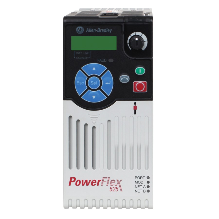
When your Allen Bradley PowerFlex 525 drive gives trouble, diagnosing the issue and getting the drive back in service quickly can be imperative. Fortunately, most problems with the PowerFlex 525 drive series VFD products can be diagnosed by the fault code indicated on its display.
Below are listed the PowerFlex 525 Fault Codes with fault number, Fault/Alarm Text, description of the fault and possible solutions. For more detailed information, see below for a link to the PowerFlex 525 troubleshooting guide.
Fault Name/Description/Action
F000 No Fault
No fault present.
——
F002 Auxiliary Input
External trip (Auxiliary) input.
• Check remote wiring.
• Verify communications programming for intentional fault.
——
F003 Power Loss
Single phase operation detected with excessive load.
• Monitor the incoming AC line for low voltage or line power interruption.
• Check input fuses.
——
F004 UnderVoltage
DC bus voltage fell below the minimum value.
• Monitor the incoming AC line for low voltage or line power interruption.
——
F005 OverVoltage
DC bus voltage exceeded maximum value.
• Monitor the AC line for high line voltage or transient conditions. Bus overvoltage can also be caused by motor regeneration. Extend the decel time or install dynamic brake option.
——
F006 Motor Stalled
Drive is unable to accelerate or decelerate motor.
• Increase P041, A442, A444, A446 [Accel Time x] or reduce load so drive output current does not exceed the current set by parameter A484, A485 [Current Limit x] for too long.
——
F007 Motor Overload
Internal electronic overload trip.
• An excessive motor load exists.
• Reduce load so drive output current does not exceed the current set by parameter P033 [Motor OL Current].
• Verify A530 [Boost Select] setting.
——
F008 Heatsink OvrTmp
Heatsink/Power Module temperature exceeds a predefined value.
• Check for blocked or dirty heat sink fins.
• Verify that ambient temperature has not exceeded the rated ambient temperature.
• Check fan.
——
F009 CC OvrTmp
Control module temperature exceeds a predefined value.
• Check product ambient temperature.
• Check for airflow obstruction.
• Check for dirt or debris.
• Check fan.
——
F012 HW OverCurrent
The drive output current has exceeded the hardware current limit.
• Check programming.
• Check for excess load, improper A530 [Boost Select] setting, DC brake volts set too high or other causes of excess current.
——
F013 Ground Fault
A current path to earth ground has been detected at one or more of the drive output terminals.
• Check the motor and external wiring to the drive output terminals for a grounded condition.
——
F015 Load Loss
The output torque current is below the value programmed in A490 [Load Loss Level] for a time period greater than the time programmed in A491 [Load Loss Time].
• Verify connections between motor and load.
• Verify level and time requirements
——
F021 Output Ph Loss
Output Phase Loss (if enabled).
Configure with A557 [Out Phas Loss En].
• Verify motor wiring.
• Verify motor.
——
F029 Analog In Loss
An analog input is configured to fault on signal loss. A signal loss has occurred. Configure with t094 [Anlg In V Loss] or t097 [Anlg In mA Loss].
• Check for broken/loose connections at inputs.
• Check parameters.
——
F033 Auto Rstrt Tries
Drive unsuccessfully attempted to reset a fault and resume running for the programmed number of A541 [Auto Rstrt Tries].
• Correct the cause of the fault and manually clear.
——
F038 Phase U to Gnd
A phase to ground fault has been detected between the drive and motor in this phase.
• Check the wiring between the drive and motor.
• Check motor for grounded phase.
——
F039 Phase V to Gnd
A phase to ground fault has been detected between the drive and motor in this phase.
• Check the wiring between the drive and motor.
• Check motor for grounded phase.
——
F040 Phase W to Gnd
A phase to ground fault has been detected between the drive and motor in this phase.
• Check the wiring between the drive and motor.
• Check motor for grounded phase.
——
F041 Phase UV Short
Excessive current has been detected between these two output terminals.
• Check the motor and drive output terminal wiring for a shorted condition.
——
F042 Phase UW Short
Excessive current has been detected between these two output terminals.
• Check the motor and drive output terminal wiring for a shorted condition.
——
F043 Phase VW Short
Excessive current has been detected between these two output terminals.
• Check the motor and drive output terminal wiring for a shorted condition.
——
F048 Params Defaulted
The drive was commanded to write default values to EEPROM.
• Clear the fault or cycle power to the drive.
• Program the drive parameters as needed.
——
F059 Safety Open
Both of the safety inputs (Safety 1, Safety 2) are not enabled. Configure with t105 [Safety Open En].
• Check safety input signals. If not using safety, verify and tighten jumper for I/O terminals S1, S2 and S+.
——
F063 SW OverCurrent
Programmed A486, A488 [Shear Pinx Level] has been exceeded for a time period greater than the time programmed in A487, A489 [Shear Pin x Time].
• Verify connections between motor and load.
• Verify level and time requirements.
——
F064 Drive Overload
Drive overload rating has been exceeded.
• Reduce load or extend Accel Time.
——
F070 Power Unit
Failure has been detected in the drive power section.
• Check maximum ambient temperature has not been exceeded.
• Cycle power.
• Replace drive if fault cannot be cleared.
——
F071 DSI Net Loss
Control over the Modbus or DSI communication link has been interrupted.
• Cycle power.
• Check communications cabling.
• Check Modbus or DSI setting.
• Check Modbus or DSI status.
——
F072 Opt Net Loss
Control over the network option card’s remote network has been interrupted.
• Cycle power.
• Check communications cabling.
• Check network adapter setting.
• Check external network status.
——
F073 EN Net Loss
Control through the embedded EtherNet/IP adapter has been interrupted.
• Cycle power.
• Check communications cabling.
• Check EtherNet/IP setting.
• Check external network status.
——
F080 Autotune Failure
The autotune function was either cancelled by the user or failed.
• Restart procedure.
——
F081 DSI Comm Loss
Communications between the drive and the Modbus or DSI master device have been interrupted.
• Cycle power.
• Check communications cabling.
• Check Modbus or DSI setting.
• Check Modbus or DSI status.
• Modify using C125 [Comm Loss Action].
• Connecting I/O terminals C1 and C2 to ground may improve noise immunity.
• Replace wiring, Modbus master device, or control module.
——
F082 Opt Comm Loss
Communications between the drive and the network option card have been interrupted.
• Cycle power.
• Reinstall option card in drive.
• Modify using C125 [Comm Loss Action].
• Replace wiring, port expander, option card, or control module.
——
F083 EN Comm Loss
Internal communications between the drive and the embedded EtherNet/IP adapter have been interrupted.
• Cycle power.
• Check EtherNet/IP setting.
• Check drive’s Ethernet settings and diagnostic parameters.
• Modify using C125 [Comm Loss Action].
• Replace wiring, Ethernet switch, or control module.
——
F091 Encoder Loss
Requires differential encoder. One of the 2 encoder channel signals is missing.
• Check Wiring.
• If P047, P049, P051 [Speed Referencex] = 16 “Positioning” and A535 [Motor Fdbk Type] = 5 “Quad Check”, swap the Encoder channel inputs or swap any two motor leads.
• Replace encoder.
——
F094 Function Loss
“Freeze-Fire” (Function Loss) input is inactive, input to the programmed terminal is open.
• Close input to the terminal and cycle power.
——
F100 Parameter Chksum
Drive parameter non-volatile storage is corrupted.
• Set P053 [Reset To Defalts] to 2 “Factory Rset”.
——
F101 External Storage
External non-volatile storage has failed.
• Set P053 [Reset To Defalts] to 2 “Factory Rset”.
——
F105 C Connect Err
Control module was disconnected while drive was powered.
• Clear fault and verify all parameter settings. Do not remove or install the control module while power is applied.
——
F106 Incompat C-P
The PowerFlex 525 control module does not support power modules with 0.25 HP power rating.
• Change to a different power module.
• Change to a PowerFlex 523 control module.
——
F107 Replaced C-P
The control module could not recognize the power module. Hardware failure.
• Change to a different power module.
• Replace control module if changing power module does not work.
——
F109 Mismatch C-P
The control module was mounted to a different drive type power module.
• Set P053 [Reset To Defalts] to 3 “Power Reset”.
——
F110 Keypad Membrane
Keypad membrane failure / disconnected.
• Cycle power.
• Replace control module if fault cannot be cleared.
——
F111 Safety Hardware
Safety input enable hardware malfunction. One of the safety inputs is not enabled.
• Check safety input signals. If not using safety, verify and tighten jumper for I/O terminals S1, S2 and S+.
• Replace control module if fault cannot be cleared.
——
F114 uC Failure
Microprocessor failure.
• Cycle power.
• Replace control module if fault cannot be cleared.
——
F122 I/O Board Fail
Failure has been detected in the drive control and I/O section.
• Cycle power.
• Replace drive or control module if fault cannot be cleared.
——
F125 Flash Update Req
The firmware in the drive is corrupt, mismatched, or incompatible with the hardware.
• Perform a firmware flash update operation to attempt to load a valid set of firmware.
——
F126 NonRecoverablErr
A non-recoverable firmware or hardware error was detected. The drive was automatically stopped and reset.
• Clear fault or cycle power to the drive.
• Replace drive or control module if fault cannot be cleared.
——
F127 DSIFlashUpdatReq
A critical problem with the firmware was detected and the drive is running using backup firmware that only supports DSI communications.
• Perform a firmware flash update operation using DSI communications to attempt to load a valid set of firmware.
——
If you determine that your PowerFlex 525 drive needs service, or you’re just not sure, give us a call at 1-800-732-4695 to send your defective VFD in for repair. We have the experience necessary to get your defective PowerFlex 525 back in operation quickly with our quality repair service.
*There is a link to the troubleshooting section of the PowerFlex 525 manual below.
-
Contents
-
Table of Contents
-
Bookmarks
Quick Links
User Manual
PowerFlex 525 Adjustable Frequency AC Drive
Original Instructions
Related Manuals for Allen-Bradley PowerFlex 525
Summary of Contents for Allen-Bradley PowerFlex 525
-
Page 1
User Manual PowerFlex 525 Adjustable Frequency AC Drive Original Instructions… -
Page 2: Important User Information
IMPORTANT Identifies information that is critical for successful application and understanding of the product. Allen-Bradley, Rockwell Automation, Rockwell Software, PowerFlex, Connected Components Workbench, Studio 5000, DriveTools SP, AppView, CustomView, MainsFree Programming, and PointStop are trademarks of Rockwell Automation, Inc. Trademarks not belonging to Rockwell Automation are property of their respective companies.
-
Page 3: Table Of Contents
Table of Contents Important User Information ……..2 Preface Overview Who Should Use this Manual .
-
Page 4
Table of Contents Advanced Display Group ……… 94 Advanced Program Group . -
Page 5
EMC Instructions……….208 Using PowerFlex 525 Safe-Torque-Off……208 Safety Concept. -
Page 6
Table of Contents Notes: Rockwell Automation Publication 520-UM001A-EN-E — February 2013… -
Page 7: Preface
Guarding Against Electrostatic Damage 8000-4.5.2 The following publications provide specific PowerFlex 520-Series information on drive installation, features, specifications, and service: Title Publication PowerFlex 525 AC Drive Specifications 520-TD001 PowerFlex Dynamic Braking Resistor Calculator PFLEX-AT001 PowerFlex AC Drives in Common Bus Configurations DRIVES-AT002…
-
Page 8: Manual Conventions
Drive as; drive, PowerFlex 520, PowerFlex 520 Drive or PowerFlex 520 AC drive. • Specific drives within the PowerFlex 520-Series may be referred to as: – PowerFlex 525, PowerFlex 525 drive or PowerFlex 525 AC drive. • Parameter numbers and names are shown in this format: P 031 [Motor NP Volts]…
-
Page 9: Drive Frame Sizes
Overview Preface Drive Frame Sizes Similar PowerFlex 525 drive sizes are grouped into frame sizes to simplify spare parts ordering, dimensioning, etc. A cross reference of drive catalog numbers and their respective frame sizes is provided in Appendix General Precautions ATTENTION: The drive contains high voltage capacitors which take time to discharge after removal of mains supply.
-
Page 10: Catalog Number Explanation
Rating Enclosure Reserved Emission Class Reserved Dash Dash Code Braking Standard Code Type 25B PowerFlex 525 Code EMC Filter No Filter Filter Code Voltage Phase Code Interface Module 120V AC 1 Standard 240V AC 1 240V AC 3 480V AC 3…
-
Page 11: Installation/Wiring
Chapter Installation/Wiring This chapter provides information on mounting and wiring the PowerFlex 525 drive. For information on… See page… Mounting Considerations AC Supply Source Considerations General Grounding Requirements Fuses and Circuit Breakers Power and Control Module Control Module Cover Power Module Terminal Guard…
-
Page 12
Chapter 1 Installation/Wiring • Do not expose to a corrosive atmosphere. • Protect from moisture and direct sunlight. Minimum Mounting Clearances Appendix B for mounting dimensions. Vertical Vertical, Zero Stacking Vertical with Control Module Fan Kit Vertical, Zero Stacking with No clearance between drives. -
Page 13
Installation/Wiring Chapter 1 Ambient Operating Temperatures Appendix B for option kits. Mounting Enclosure Rating Ambient Temperature Minimum Maximum (No Derate) Maximum (Derate) Maximum with (3)(5) Control Module Fan Kit (Derate) 50 °C (122 °F) 60 °C (140 °F) 70 °C (158 °F) Vertical IP 20/Open Type 45 °C (113 °F) -
Page 14
Chapter 1 Installation/Wiring Derating Guidelines for High Altitude The drive can be used without derating at a maximum altitude of 1000 m (3300 ft). If the drive is used above 1000 m (3300 ft): • Derate the maximum ambient temperature by 5 °C (41 °F) for every additional 1000 m (3300 ft), subject to limits listed in the Altitude Limit (Based on Voltage) -
Page 15: Ac Supply Source Considerations
AC Supply Source Ungrounded Distribution Systems Considerations ATTENTION: PowerFlex 525 contains protective MOVs that are referenced to ground. These devices must be disconnected if the drive is installed on an ungrounded or resistive grounded distribution system. ATTENTION: Removing MOVs in drives with an embedded filter will also disconnect the filter capacitor from earth ground.
-
Page 16: General Grounding Requirements
Chapter 1 Installation/Wiring Input Power Conditioning The drive is suitable for direct connection to input power within the rated voltage of the drive (see Appendix A). Listed in the Input Power Conditions table below are certain input power conditions which may cause component damage or reduction in product life.
-
Page 17
Installation/Wiring Chapter 1 Ground Fault Monitoring If a system ground fault monitor (RCD) is to be used, only Type B (adjustable) devices should be used to avoid nuisance tripping. Safety Ground — (PE) This is the safety ground for the drive that is required by code. One of these points must be connected to adjacent building steel (girder, joist), a floor ground rod or bus bar. -
Page 18: Fuses And Circuit Breakers
Installation/Wiring Fuses and Circuit Breakers The PowerFlex 525 drive does not provide branch short circuit protection. This product should be installed with either input fuses or an input circuit breaker. National and local industrial safety regulations and/or electrical codes may determine additional requirements for these installations.
-
Page 19
Installation/Wiring Chapter 1 Rockwell Automation Publication 520-UM001A-EN-E — February 2013… -
Page 20
Chapter 1 Installation/Wiring Rockwell Automation Publication 520-UM001A-EN-E — February 2013… -
Page 21
Installation/Wiring Chapter 1 Rockwell Automation Publication 520-UM001A-EN-E — February 2013… -
Page 22: Power And Control Module
Chapter 1 Installation/Wiring Power and Control Module PowerFlex 525 drives consists of a Power Module and Control Module. Separating the Power and Control Module 1. Press and hold down the catch on both sides of the frame cover, then pull out and swing upwards to remove (Frames B…E only).
-
Page 23
Installation/Wiring Chapter 1 3. Hold the sides and top of the Control Module firmly, then pull out to separate it from the Power Module. Connecting the Power and Control Module 1. Align the connectors on the Power Module and Control Module, then push the Control Module firmly onto the Power Module. -
Page 24
Chapter 1 Installation/Wiring 2. Push the top cover of the Control Module towards the Power Module to lock it. 3. Insert the catch at the top of the frame cover into the Power Module, then swing the frame cover to snap the side catches onto the Power Module (Frames B…E only). -
Page 25: Control Module Cover
Installation/Wiring Chapter 1 Control Module Cover To access the control terminals, DSI port, and Ethernet port, the front cover must be removed. To remove: 1. Press and hold down the arrow on the front of the cover. 2. Slide the front cover down to remove from the Control Module. Re-attach the front cover when wiring is complete.
-
Page 26: Power Wiring
Chapter 1 Installation/Wiring 2. Press and hold down the locking tab on the terminal guard. 3. Slide the terminal guard down to remove from the Power Module. Re-attach the terminal guard when wiring is complete. To access the power terminals for Frame A, you need to separate the Power and Control Modules.
-
Page 27
Installation/Wiring Chapter 1 UL installations above 50 °C ambient must use 600V, 90 °C wire. UL installations in 50 °C ambient must use 600V, 75 °C or 90 °C wire. UL installations in 40 °C ambient should use 600V, 75 °C or 90 °C wire. Use copper wire only. -
Page 28
Chapter 1 Installation/Wiring the overall drive performance. Unless specified in the individual distance tables as tested with the drive, these cables are not recommended and their performance against the lead length limits supplied is not known. Recommended Shielded Wire Location Rating/Type Description Standard (Option 1) 600V, 90 °C (194 °F) XHHW2/RHW-2… -
Page 29: Power Terminal Block
Installation/Wiring Chapter 1 Power Terminal Block Power Terminal Block Frame A, B, C & D Frame E L1/R L2/S L3/T T1/U T2/V T3/W L1/R L2/S L3/T T1/U T2/V T3/W DC- DC+ Terminal Description L1/R, L2/S, L3/T Input Line Voltage Connection T1/U, T2/V, T3/W Motor Phase Connection = Switch any two motor leads to change forward direction.
-
Page 30: Common Bus/Precharge Notes
Chapter 1 Installation/Wiring Common Bus/Precharge If drives are used with a disconnect switch to the common DC bus, then an auxiliary contact on the disconnect must be connected to a digital input of the Notes drive. The corresponding input (parameter t062, t063, t065…t068 [DigIn TermBlk xx]) must be set to 30, “Precharge En”…
-
Page 31
Installation/Wiring Chapter 1 Recommended Signal Wire Signal Type/ Belden Wire Type(s) Description Min. Insulation Where Used (or equivalent) Rating Analog I/O & PTC 8760/9460 0.750 mm (18 AWG), twisted pair, 300V, 60 °C (140 °F) 100% shield with drain Remote Pot 8770 0.750 mm (18 AWG), 3 conductor, shielded… -
Page 32: Control I/O Terminal Block
Chapter 1 Installation/Wiring Control I/O Terminal Block Control I/O Wiring Block Diagram Typical Typical SRC wiring SNK wiring Stop Safety 1 DigIn TermBlk 02/ Start/Run FWD Safe-Torque-Off Safety 2 DigIn TermBlk 03/ Direction/Run REV Safety +24V Digital Common DigIn TermBlk 05 DigIn TermBlk 06 DigIn TermBlk 07/Pulse DigIn TermBlk 0…
-
Page 33
Installation/Wiring Chapter 1 t064 [2-Wire Mode] Normal Stop I/O Terminal 01 Stop 0 “Edge Trigger” Per P045 Coast [Stop Mode] 1 “Level Sense” Per P045 [Stop Mode] 2 “Hi-Spd Edge” Coast 3 “Momentary” Per P045 [Stop Mode] The drive is shipped with a jumper installed between I/O Terminals 01 and 11. IMPORTANT Remove this jumper when using I/O Terminal 01 as a stop or enable input. -
Page 34
Chapter 1 Installation/Wiring Control I/O Terminal Designations No. Signal Default Description Parameter 13 ±10V In Not Active For external 0-10V (unipolar) or ±10V (bipolar) input supply or P047, P049, potentiometer wiper. t062, t063, t065, t066, Input impedance: t093, A459, Voltage source = 100 kΩ A471 Allowable potentiometer resistance range = 1…10 kΩ… -
Page 35
Installation/Wiring Chapter 1 Connection Example Analog Input Bipolar Unipolar (Voltage) Unipolar (Current) 0-10V, 100k Ω impedance P047 [Speed Reference1] P047 [Speed Reference1] P047 [Speed Reference1] 4-20 mA, 250 Ω = 5 “0-10V Input” and = 5 “0-10V Input” = 6 “4-20mA Input” t093 [10V Bipolar Enbl] impedance… -
Page 36
Chapter 1 Installation/Wiring Connection Example 2 Wire SNK Control — Internal Supply (SNK) Non-Reversing Stop-Run 2 Wire SRC Control — Internal Supply (SRC) External Supply (SRC) Run FWD/Run REV P046 [Start Source 1] = 2, t062 [DigIn TermBlk 02] = 48 and t063 [DigIn Stop-Run Forward TermBlk 03] = 50… -
Page 37
Installation/Wiring Chapter 1 Connection Example 3 Wire SRC Control — Internal Supply (SRC) External Supply (SRC) Reversing P046 [Start Source 1] = 2, Stop t062 [DigIn TermBlk 02] Stop = 49 and t063 [DigIn TermBlk 03] = 51 Start A momentary input will Start Direction start the drive. -
Page 38
Chapter 1 Installation/Wiring Typical Multiple Drive Connection Examples Input/Output Connection Example Multiple Digital Input Connections Customer Inputs can be wired per External Supply (SRC). Customer Inputs Optional Ground Connection When connecting a single input such as Run, Stop, Reverse or Preset Speeds to multiple drives, it is important to connect I/O Terminal 04 common together for all drives. -
Page 39: Start And Speed Reference Control
Installation/Wiring Chapter 1 Start and Speed Reference Start Source and Speed Reference Selection Control The start and drive speed command can be obtained from a number of different sources. By default, start source is determined by P046 [Start Source 1] and drive speed source is determined by P047 [Speed Reference1].
-
Page 40
Chapter 1 Installation/Wiring Digital Input Selection for Start Source If P046, P048 P050 [Start Source x] has been set to 2, “DigIn TermBlk”, then t062 t063 [DigIn TermBlk xx] must be configured for 2-Wire or 3-Wire control for the drive to function properly. [Start Source x] Start and Direction [DigIn TermBlk… -
Page 41: Ce Conformity
Directive has been demonstrated using harmonized European Norm (EN) standards published in the Official Journal of the European Communities. PowerFlex 525 drives comply with the EN standards listed below when installed according to the installation instructions in this manual. CE Declarations of Conformity are available online at: http://www.rockwellautomation.com/products/certification/.
-
Page 42
• For CE compliance, drives must satisfy installation requirements related to both EN 61800-5-1 and EN 61800-3 provided in this document. • PowerFlex 525 drives must be installed in a pollution degree 1 or 2 environment to be compliant with the CE LV Directive. See… -
Page 43
Installation/Wiring Chapter 1 • PowerFlex 525 drives are not intended to be used on public low-voltage networks which supply domestic premises. Without additional mitigation, radio frequency interference is expected if used on such a network. The installer is responsible to take measures such as a supplementary line filter… -
Page 44
• Motor cabling must be separated from control and signal wiring wherever possible. • Maximum motor cable length must not exceed the maximum length indicated in PowerFlex 525 RF Emission Compliance and Installation Requirements on page 45 for compliance with radio frequency emission limits for the specific standard and installation environment. -
Page 45
Building structure steel (1) Some installations require a shielded enclosure. Keep wire length as short as possible between the enclosure entry point and the EMI filter. PowerFlex 525 RF Emission Compliance and Installation Requirements Filter Type Standard/Limits EN61800-3 Category C1… -
Page 46
Chapter 1 Installation/Wiring Additional Installation Requirements Frame Size Class C1 Class C2 Enclosure and Conduit Cable EMC Cores Required Enclosure EMC Cores Required (Input and Output) 380…480V AC (-15%, +10%) – 3-Phase Input with Internal EMC Filter, 0…460V 3-Phase Output –… -
Page 47: Start Up
Chapter Start Up This chapter describes how to start up the PowerFlex 525 drive. To simplify drive setup, the most commonly programmed parameters are organized in a single Basic Program Group. For information on… See page… Prepare for Drive Start-Up…
-
Page 48
Chapter 2 Start Up 4. Verify that the Sink (SNK)/Source (SRC) jumper is set to match your control wiring scheme. See the Control I/O Wiring Block Diagram on page 32 for location. The default control scheme is Source (SRC). The Stop terminal is jumpered to IMPORTANT allow starting from the keypad or comms. -
Page 49: Display And Control Keys
Start Up Chapter 2 Display and Control Keys Menu Parameter Group and Description Basic Display Commonly viewed drive operating conditions. ENET LINK Basic Program EtherNet/IP Commonly used programmable functions. Terminal Blocks Programmable terminal functions. Communications Programmable communication functions. Logic Programmable logic functions. Advanced Display Advanced drive operating conditions.
-
Page 50: Viewing And Editing Parameters
Chapter 2 Start Up Name Description Reverse Used to reverse direction of the drive. Default is active. Controlled by parameters P046, P048 and P050 [Start Source x] and A544 [Reverse Disable]. Start Used to start the drive. Default is active. Controlled by parameters P046, P048 and P050 [Start Source x].
-
Page 51: Drive Programming Tools
[Output Freq] is displayed. Press Enter or Sel to enter the group list again. Some features in the PowerFlex 525 drive are not supported by older Drive Programming Tools configuration software tools. It is strongly recommended that customers using such tools migrate to RSLogix 5000 (version 17.0 or greater) or Logix Designer…
-
Page 52: Smart Start-Up With Basic Program Group Parameters
– Czech – – The PowerFlex 525 drive is designed so that start up is simple and efficient. The Smart Start-Up with Basic Basic Program Group contains the most commonly used parameters. See Program Group Parameters Programming and Parameters on page 57 for detailed descriptions of the parameters listed here, as well as the full list of available parameters.
-
Page 53: Lcd & Scrolling Description
Use parameter A556 [Text Scroll] to set the speed at which the text scrolls across the display. Select 0 “Off ” to turn off text scrolling. See Language Support on page 51 for the languages supported by PowerFlex 525. Rockwell Automation Publication 520-UM001A-EN-E — February 2013…
-
Page 54: Usb
Chapter 2 Start Up The PowerFlex 525 drive has a USB port that connects to a PC for the purpose of upgrading drive firmware or uploading/downloading a parameter configuration. You do not need to power up the control module. Simply connect the PowerFlex 525 drive to your PC with a USB Type B cable, and you will benefit from MainsFree™…
-
Page 55
Start Up Chapter 2 Double-click on the PF52XUSB.EXE file to launch the USB utility application. The main menu is displayed. Follow the program instructions to upgrade the firmware or upload/download configuration data. Make sure your PC is powered by an AC power outlet or has a fully charged IMPORTANT battery before starting any operation. -
Page 56
Chapter 2 Start Up Notes: Rockwell Automation Publication 520-UM001A-EN-E — February 2013… -
Page 57: Programming And Parameters
Chapter Programming and Parameters This chapter provides a complete listing and description of the PowerFlex 525 parameters. Parameters are programmed (viewed/edited) using either the drive’s built-in keypad, RSLogix 5000 version 17.0 or greater, Logix Designer version 21.0 or greater, or Connected Components Workbench version 3.0 or greater software.
-
Page 58: About Parameters
Chapter 3 Programming and Parameters About Parameters To configure a drive to operate in a specific way, drive parameters may have to be set. Three types of parameters exist: • ENUM ENUM parameters allow a selection from 2 or more items. Each item is represented by a number.
-
Page 59
Programming and Parameters Chapter 3 Logic Stp Logic 4 L184 Stp Logic Time 4 L194 Step Units 2 L204 Step Units 6 L212 Stp Logic 5 L185 Stp Logic Time 5 L195 Step Units F 2 L205 Step Units F 6 L213 Stp Logic 6 L186… -
Page 60
F684 Drv 1 Logic Cmd F709 AppView Parameter Groups PowerFlex 525 drives include various AppView™ parameter groups that groups certain parameters together for quick and easy access based on different types of applications. See AppView Parameter Groups on page 126 for more information. -
Page 61
Programming and Parameters Chapter 3 Centrifugal Pump Motor OL Current P033 Start Source 1 P046 Anlg In4-20mA Hi t096 PID 1 Diff Rate A463 Motor NP FLA P034 Speed Reference1 P047 Anlg In mA Loss t097 PID 1 Setpoint A464 Motor NP Poles P035 Relay Out1 Sel… -
Page 62
Chapter 3 Programming and Parameters CustomView Parameter Group PowerFlex 525 drives include a CustomView™ parameter group for you to store frequently used parameters for your application. See CustomView Parameter Group on page 127 for more information. Custom Group This group can store up to 100 parameters. -
Page 63: Basic Display Group
Programming and Parameters Chapter 3 Basic Display Group b001 [Output Freq] Related Parameter(s): b002, b010, P043, P044, P048, P050, P052 Output frequency present at T1, T2 & T3 (U, V & W). Does not include slip frequency. Values Default: Read Only Min/Max: 0.00/[Maximum Freq] Display:…
-
Page 64
Chapter 3 Programming and Parameters Basic Display Group (continued) b007 [Fault 1 Code] Related Parameter(s): F604-F610 b008 [Fault 2 Code] b009 [Fault 3 Code] A code that represents a drive fault. Codes appear in these parameters in the order they occur (b007 [Fault 1 Code] = the most recent fault). -
Page 65
Programming and Parameters Chapter 3 Basic Display Group (continued) b013 [Contrl In Status] Related Parameter(s): b002, P044, P045 State of the digital terminal blocks 1…3 and DB transistor. IMPORTANT Actual control commands may come from a source other than the control terminal block. 1 = Closed State, 0 = Open State DigIn TBlk 1 Digit 1… -
Page 66
Chapter 3 Programming and Parameters Basic Display Group (continued) b018 [Power Saved] Related Parameter(s): b017 Instantaneous power savings of using this drive compared to an across the line starter. Values Default: Read Only Min/Max: 0.00/655.35 kW Display: 0.01 kW b019 [Elapsed Run time] Related Parameter(s): A555 Accumulated time drive is outputting power. -
Page 67
Programming and Parameters Chapter 3 Basic Display Group (continued) b025 [Accum Cost Sav] Related Parameter(s): b024, P052, A555 Total approximate accumulated cost savings of the drive compared to using an across the line starter. [Accum Cost Sav] = [Average kWh cost] x [Accum kWh Sav] Values Default: Read Only… -
Page 68: Basic Program Group
Chapter 3 Programming and Parameters Basic Program Group P030 [Language] Language Support Selects the language displayed. A reset or power cycle is required after selection is made. HIM/LCD Display RSLogix 5000/ Connected Logix Designer Components Workbench Options 1 English (Default) 2 Français 3 Español 4 Italiano…
-
Page 69
Programming and Parameters Chapter 3 Basic Program Group (continued) P035 [Motor NP Poles] Related Parameter(s): b015 Sets the number of poles in the motor. Values Default: Min/Max: 2/40 Display: P036 [Motor NP RPM] Stop drive before changing this parameter. Sets the rated nameplate rpm of the motor. Used to calculate the rated slip of the motor. To reduce the slip frequency, set this parameter closer to the motor synchronous speed. Values Default: 1750 rpm… -
Page 70
Chapter 3 Programming and Parameters Basic Program Group (continued) P041 [Accel Time 1] Related Parameter(s): P044, A439 Sets the time for the drive to accelerate from 0 Hz to P044 [Maximum Freq]. Accel Rate = [Maximum Freq] / [Accel Time x] [Maximum Freq] Speed [Accel Time x]… -
Page 71
Programming and Parameters Chapter 3 Basic Program Group (continued) P045 [Stop Mode] Related Parameter(s): t086, t087, A434, A435 Determines the stopping mode used by the drive when a stop is initiated. Options 0 “Ramp, CF” (Default) Ramp to Stop. Stop command clears active fault. 1 “Coast, CF”… -
Page 72
Chapter 3 Programming and Parameters Basic Program Group (continued) P047 [Speed Reference1] Related Parameter(s): C125 P049 [Speed Reference2] P051 [Speed Reference3] Selects the source of speed command for the drive. Changes to these inputs take effect as soon as they are entered. P047 [Speed Reference1] is the factory default speed reference unless overridden. -
Page 73: Terminal Block Group
Programming and Parameters Chapter 3 Terminal Block Group t062 [DigIn TermBlk 02] t063 [DigIn TermBlk 03] Related Parameter(s): b012, b013, b014, P045, P046, P048, P049, P050, P051, t064, t065 [DigIn TermBlk 05] t066 [DigIn TermBlk 06] t086, A410-A425, A427, A431, A432, A433, A434, A435, t067 [DigIn TermBlk 07] t068 [DigIn TermBlk 08] A442, A443, A488, A535, A560, A562, A563, A567,…
-
Page 74
Chapter 3 Programming and Parameters Options 27 “Anlg Invert” Inverts the scaling of the analog input levels set in t091 [Anlg In 0-10V Lo] and t092 [Anlg In 0-10V Hi] or t095 [Anlg In4-20mA Lo] and t096 [Anlg In4-20mA Hi]. 28 “EM Brk Rlse”… -
Page 75
Programming and Parameters Chapter 3 Options 47 Reserved 48 “2-Wire FWD” [DigIn TermBlk 02] default. Selects 2-Wire FWD for this input. (only for DigIn TermBlk 02) Select this option and set P046, P048 P050 [Start Source x] to 2 “DigIn TrmBlk” to configure [Start Source x] to a 2-wire run forward mode. -
Page 76
Chapter 3 Programming and Parameters Terminal Block Group (continued) ì t069 [Opto Out1 Sel] Related Parameter(s): P046, P048, P050, t070, t073, t077, t082, t072 [Opto Out2 Sel] t086, t087, t093, t094, t097, A541, A564 Determines the operation of the programmable digital outputs. Options Setting Output Changes State When… -
Page 77
Programming and Parameters Chapter 3 Terminal Block Group (continued) t070 [Opto Out1 Level] Related Parameter(s): t069, t072 t073 [Opto Out2 Level] 32 bit parameter. Determines the on/off point for the digital outputs when t069 t072 [Opto Outx Sel] is set to the values shown below. Min/Max Value Range Based On [Opto Outx Sel] Setting 6: 0…500 Hz 10: 0…100%… -
Page 78
Chapter 3 Programming and Parameters Terminal Block Group (continued) t076 [Relay Out1 Sel] Related Parameter(s): P046, P048, P050, t070, t073, t077, t082, t081 [Relay Out2 Sel] t086, t087, t093, t094, t097, A541, A564 Determines the operation of the programmable output relay. Options Output Relay Changes State When… -
Page 79
Programming and Parameters Chapter 3 Terminal Block Group (continued) t077 [Relay Out1 Level] Related Parameter(s): t076, t081 t082 [Relay Out2 Level] 32 bit parameter. Determines the on/off point for the output relay when t076 t081 [Relay Outx Sel] is set to the values shown below. Min/Max Value Range Based On [Relay Outx Sel] Setting 6: 0…500 Hz 10: 0…100%… -
Page 80
Chapter 3 Programming and Parameters Terminal Block Group (continued) t087 [EM Brk On Delay] Related Parameter(s): P045 Sets the time the drive remains at minimum frequency (after releasing the brake coil relay) before stopping if EM Brake Control Mode is enabled with P045 [Stop Mode]. -
Page 81
Programming and Parameters Chapter 3 Terminal Block Group (continued) t089 [Analog Out High] Scales the maximum output value (V or mA) when the source setting is at maximum. Values Default: 100% Min/Max: 0/800% Display: t090 [Anlg Out Setpt] Related Parameter(s): t088 Sets the percentage of output desired when t088… -
Page 82
Chapter 3 Programming and Parameters Terminal Block Group (continued) t094 [Anlg In V Loss] Related Parameter(s): P043, P044, A426, A427 Sets the response to a loss of input. When the 0-10V input (or –10 to +10V) is used for any reference, any input less than 1V is reported as a signal loss. Input must exceed 1.5V for the signal loss condition to end. -
Page 83
Programming and Parameters Chapter 3 Terminal Block Group (continued) t098 [Anlg Loss Delay] Related Parameter(s): t094, t097 Sets the length of time after power-up during which the drive detects no analog signal loss. Response to an analog signal loss is set in t094 t097 [Analog In x Loss]. -
Page 84
Chapter 3 Programming and Parameters Terminal Block Group (continued) t104 [Wake Time] Sets the analog input time the drive must stay above to wake from sleep mode. Values Default: 0.0 s Min/Max: 0.0/600.0 s Display: 0.1 s t105 [Safety Open En] Sets the action when both safety inputs (Safety 1 and Safety 2) are disabled (de-energized –… -
Page 85: Communications Group
Programming and Parameters Chapter 3 Communications Group C121 [Comm Write Mode] Saves parameter values in active drive memory (RAM) or in drive non-volatile memory (EEPROM). ATTENTION: If Automatic Drive Configuration (ADC) is used, this parameter must remain at its default value of 0 “Save”. IMPORTANT Parameter values set prior to setting 1 “RAM only”…
-
Page 86
Chapter 3 Programming and Parameters Communications Group (continued) C127 [RS485 Format] Determines the details related to the specific Modbus protocol used by the drive. A reset or power cycle is required after selection is made. Options 0 “RTU 8-N-1” (Default) 1 “RTU 8-E-1”… -
Page 87
Programming and Parameters Chapter 3 Communications Group (continued) C137 [EN Gateway Cfg 1] Related Parameter(s): C128 C138 [EN Gateway Cfg 2] C139 [EN Gateway Cfg 3] C140 [EN Gateway Cfg 4] Sets the bytes of the gateway address. A reset or power cycle is required after selection is made. 192.168.1.1 [EN Gateway Cfg 1] [EN Gateway Cfg 2]… -
Page 88
Chapter 3 Programming and Parameters Communications Group (continued) C144 [EN Idle Flt Actn] Related Parameter(s): P045, C145, C146, C147-C150 Sets the action that the EtherNet/IP interface and drive takes if the EtherNet/IP interface detects that the scanner is idle because the controller was switched to program mode. ATTENTION: Risk of injury or equipment damage exists. -
Page 89
Programming and Parameters Chapter 3 Communications Group (continued) C157 [EN Data Out 1] C158 [EN Data Out 2] C159 [EN Data Out 3] C160 [EN Data Out 4] Datalink parameter number whose value is read from the embedded EtherNet/IP data table. Values Default: Min/Max:… -
Page 90
Chapter 3 Programming and Parameters C175 [DSI I/O Cfg] Sets the configuration of the Drives that are active in the multi-drive mode. Identifies the connections that would be attempted on a reset or power cycle. A reset or power cycle is required after selection is made. -
Page 91: Logic Group
Programming and Parameters Chapter 3 Logic Group L180 [Stp Logic 0] L181 [Stp Logic 1] Related Parameter(s): L182 [Stp Logic 2] L183 [Stp Logic 3] L184 [Stp Logic 4] L185 [Stp Logic 5] L186 [Stp Logic 6] L187 [Stp Logic 7] Stop drive before changing this parameter.
-
Page 92
Chapter 3 Programming and Parameters StepLogic Settings The logic for each function is determined by the four digits for each StepLogic parameter. The following is a listing of the available settings for each digit. See Appendix D for more information. Logic for next step Digit 1 Logic to jump to a different step… -
Page 93
Programming and Parameters Chapter 3 Logic Group (continued) L190 [Stp Logic Time 0] L191 [Stp Logic Time 1] L192 [Stp Logic Time 2] L193 [Stp Logic Time 3] L194 [Stp Logic Time 4] L195 [Stp Logic Time 5] L196 [Stp Logic Time 6] L197 [Stp Logic Time 7] Sets the time to remain in each step if the corresponding command word is set to “Step based on time”. -
Page 94: Advanced Display Group
Chapter 3 Programming and Parameters Advanced Display Group d360 [Analog In 0-10V] Related Parameter(s): t091, t092 Displays the 0-10V analog input as a percent of full scale. Values Default: Read Only Min/Max: 0.0/100.0% Display: 0.1% d361 [Analog In 4-20mA] Related Parameter(s): t095, t096 Displays the 4-20 mA analog input as a percent of full scale.
-
Page 95
Programming and Parameters Chapter 3 Advanced Display Group (continued) d368 [Testpoint Data] Related Parameter(s): A483 Displays the present value of the function selected in A483 [Testpoint Sel]. Values Default: Read Only Min/Max: 0/FFFF Display: d369 [Motor OL Level] Displays the motor overload counter. Values Default: Read Only… -
Page 96
Chapter 3 Programming and Parameters Advanced Display Group (continued) d382 [Torque Current] Displays the current value of the motor torque current measured by the drive. Values Default: Read Only Min/Max: 0.00/(Drive Rated Amps x 2) Display: 0.01 A d383 [PID1 Fdbk Displ] d385 [PID2 Fdbk Displ] Displays the active PID Feedback value. -
Page 97
Programming and Parameters Chapter 3 Advanced Display Group (continued) d390 [Fiber Status] Present status of the Fibers features. 1 = Condition True, 0 = Condition False Sync Hold Digit 1 Sync Ramp Digit 2 Traverse On Digit 3 Traverse Dec Digit 4 Not Used Values… -
Page 98: Advanced Program Group
Chapter 3 Programming and Parameters Advanced Program Group A410 [Preset Freq 0] A411 [Preset Freq 1] A412 [Preset Freq 2] A413 [Preset Freq 3] A414 [Preset Freq 4] A415 [Preset Freq 5] A416 [Preset Freq 6] A417 [Preset Freq 7] A418 [Preset Freq 8] A419 [Preset Freq 9] A420 [Preset Freq 10]…
-
Page 99
Programming and Parameters Chapter 3 Advanced Program Group (continued) A428 [MOP Reset Sel] Determines if the current MOP reference command is saved on power down. Options 0 “Zero MOP Ref” Resets the MOP frequency to zero on power down. 1 “Save MOP Ref” (Default) A429 [MOP Preload] Determines the operation of the MOP function. -
Page 100
Chapter 3 Programming and Parameters Advanced Program Group (continued) A435 [DC Brake Level] Related Parameter(s): P045 Defines the maximum DC brake current, in amps, applied to the motor when P045 [Stop Mode] is set to either 4 “Ramp” or 6 “DC Brake”. Ramp-to-Stop Mode DC Injection Stop Mode [DC Brake Time]… -
Page 101
Programming and Parameters Chapter 3 Advanced Program Group (continued) A439 [S Curve %] Enables a fixed shape S-Curve that is applied to the acceleration and deceleration ramps (including jog). S-Curve Time = (Accel or Decel Time) x (S-Curve Setting in percentage) Example: 100% S-Curve 50% S-Curve… -
Page 102
Chapter 3 Programming and Parameters Advanced Program Group (continued) A442 [Accel Time 2] Related Parameter(s): P044 Time for the drive to ramp from 0.0 Hz to P044 [Maximum Freq] if Accel Time 2 is selected. Accel Rate = [Maximum Freq] / [Accel Time] [Maximum Freq] Speed [Accel Time x]… -
Page 103
Programming and Parameters Chapter 3 Advanced Program Group (continued) A449 [Skip Freq Band 1] Related Parameter(s): A448, A450, A452, A454 A451 [Skip Freq Band 2] A453 [Skip Freq Band 3] A455 [Skip Freq Band 4] Determines the band around A448, A450, A452 A454 [Skip Frequency x]. -
Page 104
Chapter 3 Programming and Parameters Advanced Program Group (continued) A458 [PID 1 Trim Sel] A470 [PID 2 Trim Sel] Stop drive before changing this parameter. Sets the PID output as trim to the source reference. Options 0 “Disabled” (Default) PID Trim is disabled. 1 “TrimOn Pot”… -
Page 105
Programming and Parameters Chapter 3 Advanced Program Group (continued) A460 [PID 1 Fdback Sel] A472 [PID 2 Fdback Sel] Selects the source of the PID feedback. Options 0 “0-10V Input” (Default) Note: PID does not function with bipolar input. Negative voltages are ignored and treated as zero. 1 “4-20mA Input”… -
Page 106
Chapter 3 Programming and Parameters Advanced Program Group (continued) A466 [PID 1 Preload] A478 [PID 2 Preload] Sets the value used to preload the integral component on start or enable. Values Default: 0.0 Hz Min/Max: 0.0/500.0 Hz Display: 0.1 Hz A467 [PID 1 Invert Err] A479 [PID 2 Invert Err] Changes the sign of the PID error. -
Page 107
Programming and Parameters Chapter 3 Advanced Program Group (continued) A486 [Shear Pin1 Level] Related Parameter(s): A487, A489 A488 [Shear Pin2 Level] Sets the value of current at which the shear pin fault occurs after the time set in A487, A489 [Shear Pin x Time]. -
Page 108
Chapter 3 Programming and Parameters Advanced Program Group (continued) A493 [Motor OL Select] Related Parameter(s): P032, P033 Drive provides Class 10 overload protection. Settings 0…2 select the derating factor for the I t overload function. No Derate Min Derate Max Derate % of [Motor NP Hertz] % of [Motor NP Hertz] % of [Motor NP Hertz]… -
Page 109
Programming and Parameters Chapter 3 Advanced Program Group (continued) A499 [Motor Lm] Mutual Inductance of induction motor. Values Default: Based on Drive Rating Min/Max: 0.0/6553.5 mH Display: 0.1 mH A500 [Motor Lx] Leakage Inductance of induction motor. Values Default: Based on Drive Rating Min/Max: 0.0/6553.5 mH Display:… -
Page 110
Chapter 3 Programming and Parameters Advanced Program Group (continued) A522 [Freq 1 Ki] Related Parameter(s): A509, A510 A524 [Freq 2 Ki] A526 [Freq 3 Ki] Sets I-gain of “Vector” control mode when in frequency region 1, 2 or 3 for faster speed response during steady-state where motor is at its rated speed. If A509 [Speed Reg Sel] is set to 1 “Manual”, these parameters can be changed. -
Page 111
Programming and Parameters Chapter 3 Advanced Program Group (continued) A531 [Start Boost] Related Parameter(s): P031, P032, P039, A530 Sets the boost voltage (% of P031 [Motor NP Volts]) and redefines the V/Hz curve when A530 [Boost Select] = 0 “Custom V/Hz” and P039 [Torque Perf Mode] = 0 “V/Hz”. -
Page 112
Chapter 3 Programming and Parameters Advanced Program Group (continued) A535 [Motor Fdbk Type] Related Parameter(s): A537 Stop drive before changing this parameter. Selects the encoder type. ATTENTION: The loss of analog input, encoder or other feedback may cause unintended speed or motion. Take appropriate precautions to guard against possible unintended speed or motion. -
Page 113
Programming and Parameters Chapter 3 Advanced Program Group (continued) A541 [Auto Rstrt Tries] Related Parameter(s): A542 Sets the maximum number of times the drive attempts to reset a fault and restart. See Chapter 4 for more information on faults and fault codes. Clear a Type 1 fault and restart the drive. -
Page 114
Chapter 3 Programming and Parameters Advanced Program Group (continued) A547 [Compensation] Enables/disables correction options that may improve problems with motor instability. Options 0 “Disabled” No compensation. 1 “Electrical” (Default) Some drive/motor combinations have inherent instabilities which are exhibited as non-sinusodial motor currents. This setting attempts to correct this condition 2 “Mechanical”… -
Page 115
Programming and Parameters Chapter 3 Advanced Program Group (continued) A554 [Drv Ambient Sel] Sets the maximum expected ambient of the drive when used above 50 °C. When ambient temperature is above 50 °C, the drive will apply necessary current derating. Options 0 “Normal”… -
Page 116
Chapter 3 Programming and Parameters Advanced Program Group (continued) A560 [Enh Control Word] Related Parameter(s): t062, t063, t065 — t068, A571 Allows control of positioning and other functions through parameter control for use over comms. The functions replicate the digital input options and function in the same way. 1 = Input Present, 0 = Input Not Present Home Limit Digit 1… -
Page 117
Programming and Parameters Chapter 3 Advanced Program Group (continued) A564 [Encoder Pos Tol] Sets the “At Position” and the “At Home’ tolerance around the encoder count. The value is added to and subtracted from the target encoder unit value to create the tolerance range. Values Default: Min/Max:… -
Page 118: Network Parameter Group
Chapter 3 Programming and Parameters Advanced Program Group (continued) A570 [P Jump] Related Parameter(s): A567 Sets the frequency amplitude that is added to or subtracted from the commanded frequency. See the diagram at A567 [Max Traverse]. Values Default: 0.00 Hz Min/Max: 0.00/300.00 Hz Display:…
-
Page 119: Fault And Diagnostic Group
Programming and Parameters Chapter 3 Fault and Diagnostic Group F604 [Fault 4 Code] Related Parameter(s): b007-b009 F605 [Fault 5 Code] F606 [Fault 6 Code] F607 [Fault 7 Code] F608 [Fault 8 Code] F609 [Fault 9 Code] F610 [Fault10 Code] A code that represents a drive fault. The codes appear in these parameters in the order they occur (b007 [Fault 1 Code] = the most recent fault). Repetitive faults are only recorded once. Values Default: Read Only…
-
Page 120
Chapter 3 Programming and Parameters Fault and Diagnostic Group (continued) F641 [Fault 1 Current] F642 [Fault 2 Current] Related Parameter(s): b003 F643 [Fault 3 Current] F644 [Fault 4 Current] F645 [Fault 5 Current] F646 [Fault 6 Current] F647 [Fault 7 Current] F648 [Fault 8 Current] F649 [Fault 9 Current] F650 [Fault10 Current]… -
Page 121
Programming and Parameters Chapter 3 Fault and Diagnostic Group (continued) F682 [Comm Sts — Opt] Displays the status of the internal communication to the drive. Digit 3 = “Internal Com option” 1 = Condition True, 0 = Condition False “Not Active (no connection)” Digit 1 “Internal option connected/active”… -
Page 122
Chapter 3 Programming and Parameters Fault and Diagnostic Group (continued) F686 [DSI I/O Act] Displays the Drives that are active in Multi-Drive mode. 1 = Drive Inactive, 0 = Drive Active Drive 0 Actv Digit 1 Drive 1 Actv Digit 2 Drive 2 Actv Digit 3 Drive 3 Actv… -
Page 123
Programming and Parameters Chapter 3 Fault and Diagnostic Group (continued) F697 [EN Subnet Act 1] F698 [EN Subnet Act 2] F699 [EN Subnet Act 3] F700 [EN Subnet Act 4] Shows the actual subnet mask used by the embedded EtherNet/IP interface at the time. This will indicate 0 if no address is set. 255.255.255.255 [EN Subnet Act 1] [EN Subnet Act 2]… -
Page 124
Chapter 3 Programming and Parameters Fault and Diagnostic Group (continued) F706 [Drv 0 Reference] F710 [Drv 1 Reference] F714 [Drv 2 Reference] F718 [Drv 3 Reference] F722 [Drv 4 Reference] In multi-drive mode, this is the reference being transmitted to drive 0/1/2/3/4. In single-drive mode, this is the reference being used by the drive (whether HS-DSI, EtherNet/IP, or DSI) at the time. -
Page 125
Programming and Parameters Chapter 3 Fault and Diagnostic Group (continued) F728 [EN Tx Packets] A count of the number of transmitted packets reported by the embedded EtherNet/IP interface. Values Default: Read Only Min/Max: 0/65535 Display: F729 [EN Tx Errors] A count of the number of transmit errors reported by the embedded EtherNet/IP interface. Values Default: Read Only… -
Page 126: Appview Parameter Groups
Chapter 3 Programming and Parameters AppView Parameter Groups PowerFlex 525 drives include various AppView parameter groups that groups certain parameters together for quick and easy access based on different types of applications. These applications include: • Conveyor • Mixer • Compressor •…
-
Page 127: Customview Parameter Group
Programming and Parameters Chapter 3 CustomView Parameter Use the CustomView parameter group to: • store frequently used parameters for your application for quicker access. Group • select only those parameters needed for your application and if required, hide all other parameters with A552 [Program Lock].
-
Page 128: Parameter Cross Reference By Name
Chapter 3 Programming and Parameters Parameter Cross Reference by Name Parameter Name Parameter Name Parameter Name 10V Bipolar Enbl DB Resistor Sel DSI Errors 2-Wire Mode DB Threshold DSI I/O Act Accel Time 1 DC Brake Level DSI I/O Cfg Accel Time 2 DC Brake Time Elapsed kWh…
-
Page 129
Programming and Parameters Chapter 3 Parameter Name Parameter Name Parameter Name EN Rx Overrruns Fault 6 Current HW Addr 2 EN Rx Packets Fault 6 Freq HW Addr 3 EN Subnet Act 1 Fault 6 Time-hr HW Addr 4 EN Subnet Act 2 Fault 6 Time-min HW Addr 5 EN Subnet Act 3… -
Page 130
Chapter 3 Programming and Parameters Parameter Name Parameter Name Parameter Name Output Voltage Preset Freq 13 Sleep Level Opto Out2 LevelF Preset Freq 14 Sleep Time Opto Out2 Sel Preset Freq 15 Sleep-Wake Sel Out Phas Loss En Preset Freq 2 Slip Hz Meter Output Current Preset Freq 3… -
Page 131
Programming and Parameters Chapter 3 Parameter Name Parameter Name Parameter Name Stp Logic 6 Stp Logic Time 6 Torque Perf Mode Stp Logic 7 Stp Logic Time 7 Traverse Dec Stp Logic Status Sync Time Traverse Inc Stp Logic Time 0 Testpoint Data Units Traveled H Stp Logic Time 1… -
Page 132
Chapter 3 Programming and Parameters Notes: Rockwell Automation Publication 520-UM001A-EN-E — February 2013… -
Page 133: Drive Status
Chapter Troubleshooting This chapter provides information to guide you in troubleshooting the PowerFlex 525 drive. Included is a listing and description of drive faults with possible solutions, when applicable. For information on… See page… Drive Status Faults Fault Descriptions Common Symptoms and Corrective Actions ATTENTION: Risk of injury or equipment damage exists.
-
Page 134
Chapter 4 Troubleshooting Fault Indication Condition Display Drive is indicating a fault. The integral LCD display provides visual notification of a fault condition by displaying the following. • Flashing fault number FAULT • Flashing fault indicator (LED) Press the Esc key to regain control of the display. Manually Clearing Faults Step Key(s) -
Page 135: Fault Descriptions
Troubleshooting Chapter 4 Auto Restart (Reset/Run) The Auto Restart feature provides the ability for the drive to automatically perform a fault reset followed by a start attempt without user or application intervention. This allows remote or “unattended” operation. Only certain faults are allowed to be reset.
-
Page 136
Chapter 4 Troubleshooting Fault Types, Descriptions and Actions No. Fault Type Description Action F015 Load Loss The output torque current is below the • Verify connections between motor value programmed in A490 [Load Loss and load. Level] for a time period greater than the •… -
Page 137
Troubleshooting Chapter 4 Fault Types, Descriptions and Actions No. Fault Type Description Action F081 DSI Comm Loss Communications between the drive and • Cycle power. the Modbus or DSI master device have • Check communications cabling. been interrupted. • Check Modbus or DSI setting. •… -
Page 138: Common Symptoms And Corrective Actions
Chapter 4 Troubleshooting Fault Types, Descriptions and Actions No. Fault Type Description Action F122 I/O Board Fail Failure has been detected in the drive • Cycle power. control and I/O section. • Replace drive or control module if fault cannot be cleared. F125 Flash Update Req The firmware in the drive is corrupt, Perform a firmware flash update…
-
Page 139
Incorrect input wiring. None • Wire inputs correctly and/or install jumper. • If the PowerFlex 525 Safe-Torque-Off function is used, verify that inputs are active. page 34 for wiring examples. • If 2-wire or 3-wire mode is used, verify that… -
Page 140
Chapter 4 Troubleshooting Drive does not respond to changes in speed command. Cause(s) Indication Corrective Action No value is coming from the source of the command. The drive “Run” indicator is • Check b012 [Control Source] for correct source. lit and output is 0 Hz. •… -
Page 141
Troubleshooting Chapter 4 Drive does not power up. Cause(s) Indication Corrective Action No input power to drive. None • Check the power circuit. • Check the supply voltage. • Check all fuses and disconnects. Control module is not connected properly to power module. None 1. -
Page 142
Chapter 4 Troubleshooting Notes: Rockwell Automation Publication 520-UM001A-EN-E — February 2013… -
Page 143: Drives, Fuse & Circuit Breaker Ratings
Appendix Supplemental Drive Information For information on… See page… Drives, Fuse & Circuit Breaker Ratings Specifications Drives, Fuse & Circuit Breaker The tables found in Fuses and Circuit Breakers on page 18 provide drive ratings and recommended AC line input fuse and circuit breaker information. Both Ratings types of short circuit protection are acceptable for UL and IEC requirements.
-
Page 144: Specifications
Appendix A Supplemental Drive Information Specifications Category PowerFlex 525 Certifications c-UL-us Listed to UL508C and CAN/CSA-C22.2 No. 14-05. C-Tick Australian Communications and Media Authority In conformity with the following: Radiocommunications Act: 1992 Radiocommunications Standard: 2008 N223 Radiocommunications Labelling Notice: 2008…
-
Page 145
Supplemental Drive Information Appendix A Category Specifications Protection Bus Overvoltage Trip 100…120V AC Input: 405V DC bus (equivalent to 150V AC incoming line) 200…240V AC Input: 405V DC bus (equivalent to 290V AC incoming line) 380…480V AC Input: 810V DC bus (equivalent to 575V AC incoming line) 525…600V AC Input: 1005V DC bus (equivalent to 711V AC incoming line) Bus Undervoltage Trip… -
Page 146
Appendix A Supplemental Drive Information Category Specifications Environment Sound Pressure Level (A-weighted) Measurements are taken 1 m from the drive. Frame A & B: Maximum 53 dBA Frame C: Maximum 57 dBA Frame D: Maximum 64 dBA Frame E: Maximum 68 dBA Electrical Voltage Tolerance: -15% / +10%… -
Page 147
(1) Non-Isolated 0-10V or 4-20 mA Specification Resolution: 10-bit 0-10V DC Analog: 1 k ohm minimum 4-20 mA Analog: 525 ohm maximum PowerFlex 525 Estimated Watts Loss (Rated Load, Speed & PWM) Voltage Output Current (A) Total Watts Loss 100…120V, 27.0 50/60 Hz 1-Phase 53.0 67.0… -
Page 148
Appendix A Supplemental Drive Information PowerFlex 525 Estimated Watts Loss (Rated Load, Speed & PWM) Voltage Output Current (A) Total Watts Loss 380…480V, 27.0 50/60 Hz 3-Phase 37.0 80.0 86.0 10.5 129.0 13.0 170.0 17.0 221.0 24.0 303.0 30.0 387.0 380…480V,… -
Page 149: Product Selection
Appendix Accessories and Dimensions Product Selection Catalog Number Description Drive Voltage Rating Rating Enclosure Emission Class Version PowerFlex 525 Drives Output Ratings Normal Duty Heavy Duty Output Input Frame Catalog No. Current (A) Voltage Range Size 100…120V AC (-15%, +10%) – 1-Phase Input, 0…230V 3-Phase Output 25B-V2P5N104 85…132…
-
Page 150
Appendix B Accessories and Dimensions PowerFlex 525 Drives Output Ratings Normal Duty Heavy Duty Output Input Frame Catalog No. Current (A) Voltage Range Size 380…480V AC (-15%, +10%) – 3-Phase Input with EMC Filter, 0…460V 3-Phase Output 25B-D1P4N114 323…528 25B-D2P3N114 0.75… -
Page 151
Accessories and Dimensions Appendix B Dynamic Brake Resistors Drive Ratings Minimum Resistance Resistance Input Voltage Ω ±10% Ω ±5% (1)(2) Catalog No. 100…120V AK-R2-091P500 50/60 Hz 0.75 AK-R2-091P500 1-Phase AK-R2-091P500 200…240V AK-R2-091P500 50/60 Hz 0.75 AK-R2-091P500 1-Phase AK-R2-091P500 AK-R2-047P500 200…240V AK-R2-091P500 50/60 Hz 0.75… -
Page 152
Appendix B Accessories and Dimensions EMC Line Filters Drive Ratings Input Voltage Current (A) Frame Size Catalog No. 100…120V 25-RF011-AL 50/60 Hz 0.75 25-RF023-BL 1-Phase 25-RF023-BL 200…240V 25-RF011-AL 50/60 Hz 0.75 25-RF011-AL 1-Phase 25-RF023-BL 11.0 25-RF023-BL 200…240V 25-RF014-AL 50/60 Hz 0.75 25-RF014-AL 3-Phase… -
Page 153
Accessories and Dimensions Appendix B Human Interface Module (HIM) Option Kits and Accessories Item Description Catalog No. LCD Display, Remote Panel Digital speed control 22-HIM-C2S Mount CopyCat capable IP66 (NEMA Type 4X/12) indoor use only Includes 2.9 meter cable LCD Display, Remote Digital speed control 22-HIM-A3 Handheld… -
Page 154
Appendix B Accessories and Dimensions Replacement Parts PowerFlex 520-Series Power Module Item Description PowerFlex 525 Power Replacement power module for use with PowerFlex 520-Series drives. Includes: Module • Power Module • Power Module Front Cover • Power Terminal Guard • Heatsink Fan… -
Page 155
32.0 446…660 25-PM1-E032 PowerFlex 520-Series Control Module Frame Item Description Size Catalog No. PowerFlex 525 Control Replacement control module for use with A…E 25B-CTM1 Module PowerFlex 520-Series drives. Includes: • Control Module • Control Module Front Cover Other Parts Frame… -
Page 156
AK-U0-RJ45-TR1 Terminal Block RJ45 Two position terminal block (5 pieces) AK-U0-RJ45-TB2P Connected Components Windows-based software packages for programming and http:// Workbench Software configuring Allen-Bradley drives and other Rockwell ab.rockwellautomation.co (Download or DVD-ROM) Automation products. m/programmable- controllers/connected- Compatibility: components-workbench- Windows XP, Windows Vista and Windows 7… -
Page 157: Product Dimensions
(3) Input line reactors were sized based on the NEC fundamental motor amps. Output line reactors were sized based on the VFD rated output currents. The PowerFlex 525 drive is available in five frame sizes. See PowerFlex 525 Drives Product Dimensions on page 149 for information on power ratings.
-
Page 158
Appendix B Accessories and Dimensions IP 20/Open Type – Frame A Dimensions are in millimeters and (inches) 72.0 (2.83) 172.0 (6.77) 57.5 (2.26) 6.0 (0.24) IP 20/Open Type – Frame B Dimensions are in millimeters and (inches) 87.0 (3.43) 172.0 (6.77) 72.5 (2.85) 6.0 (0.24) Rockwell Automation Publication 520-UM001A-EN-E — February 2013… -
Page 159
Accessories and Dimensions Appendix B IP 20/Open Type – Frame C Dimensions are in millimeters and (inches) 109.0 (4.29) 184.0 (7.24) 90.5 (3.56) 6.0 (0.24) IP 20/Open Type – Frame D Dimensions are in millimeters and (inches) 130.0 (5.12) 212.0 (8.35) 116.0 (4.57) 6.0 (0.24) Rockwell Automation Publication 520-UM001A-EN-E — February 2013… -
Page 160
Appendix B Accessories and Dimensions IP 20/Open Type – Frame E Dimensions are in millimeters and (inches) 185.0 (7.28) 279.0 (10.98) 160.0 (6.30) 7.6 (0.30) Rockwell Automation Publication 520-UM001A-EN-E — February 2013… -
Page 161
Accessories and Dimensions Appendix B IP 20/Open Type with Control Module Fan Kit – Frame A…E Dimensions are in millimeters and (inches) Frame A Frame B Frame C 109.0 (4.29) 72.0 (2.83) 87.0 (3.43) 72.5 (2.85) 57.5 (2.26) 90.5 (3.56) Frame D Frame E 196.0 (7.72) -
Page 162
Appendix B Accessories and Dimensions IP 30/NEMA 1/UL Type 1 – Frame A Dimensions are in millimeters and (inches) IP 30/NEMA 1/ UL Type 1 top panel 72.0 (2.83) 57.5 (2.26) 172.0 (6.77) 6.0 (0.24) IP 30/NEMA 1/ UL Type 1 conduit box 51.1 (2.01) 21.0 (0.82) ø21.5 (ø0.85) -
Page 163
Accessories and Dimensions Appendix B IP 30/NEMA 1/UL Type 1 – Frame B Dimensions are in millimeters and (inches) IP 30/NEMA 1/ UL Type 1 top panel 87.0 (3.43) 172.0 (6.77) 72.5 (2.85) 6.1 (0.24) IP 30/NEMA 1/ UL Type 1 conduit box 66.1 (2.60) 63.1 (2.48) 33.5 (1.32) -
Page 164
Appendix B Accessories and Dimensions IP 30/NEMA 1/UL Type 1 – Frame C Dimensions are in millimeters and (inches) IP 30/NEMA 1/ UL Type 1 top panel 109.0 (4.29) 90.5 (3.56) 184.0 (7.24) 6.0 (0.24) IP 30/NEMA 1/ UL Type 1 conduit box 80.5 (3.17) 66.5 (2.62) 34.5 (1.36) -
Page 165
Accessories and Dimensions Appendix B IP 30/NEMA 1/UL Type 1 – Frame D Dimensions are in millimeters and (inches) IP 30/NEMA 1/ UL Type 1 top panel 130.0 (5.12) 212.0 (8.35) 116.0 (4.57) 6.0 (0.24) IP 30/NEMA 1/ UL Type 1 conduit box 96.0 (3.78) 70.0 (2.76) 44.0 (1.73) -
Page 166
Appendix B Accessories and Dimensions IP 30/NEMA 1/UL Type 1 – Frame E Dimensions are in millimeters and (inches) IP 30/NEMA 1/ UL Type 1 top panel 185.0 (7.28) 160.0 (6.30) 279.0 (10.98) 7.6 (0.30) IP 30/NEMA 1/ UL Type 1 conduit box 127.5 (5.02) 82.5 (3.25) 62.5 (2.46) -
Page 167
Accessories and Dimensions Appendix B EMC Line Filter – Frame A Dimensions are in millimeters and (inches) Filter can be mounted onto the back of the drive. 55.0 (2.17) 72.0 (2.83) 30.0 (1.18) 54.0 (2.13) ø5.5 (ø0.22) 234.0 223.0 (9.21) 223.0 (8.78) (8.78) 20.0 (0.79) -
Page 168
Appendix B Accessories and Dimensions EMC Line Filter – Frame C Dimensions are in millimeters and (inches) Filter can be mounted onto the back of the drive. 70.0 (2.76) 109.0 (4.29) 37.0 (1.46) 76.0 (2.99) ø5.5 (ø0.22) 275.0 (10.83) 263.0 263.0 (10.35) (10.35) -
Page 169
Accessories and Dimensions Appendix B EMC Line Filter – Frame E Dimensions are in millimeters and (inches) 80.0 (3.15) 155.0 (6.10) 33.0 (1.30) 28.0 (1.10) 110.0 (4.33) ø5.5 (ø0.22) 390.0 (15.35) 375.0 375.0 (14.76) (14.76) 33.0 (1.30) 28.0 (1.10) 5.5 (0.22) 110.0 (4.33) Rockwell Automation Publication 520-UM001A-EN-E — February 2013… -
Page 170: Optional Accessories And Kits
Appendix B Accessories and Dimensions Optional Accessories and Kits Installing a Communication Adapter 1. Insert the communication adapter interface connector into the Control Module. Make sure the indicator line on the connector is aligned with the surface of the Control Module. Communication adapter interface connector…
-
Page 171
Accessories and Dimensions Appendix B Removing a Communication Adapter 1. Insert a finger into the slot at the top of the back cover. Lift to separate the back cover from the Control Module. Rockwell Automation Publication 520-UM001A-EN-E — February 2013… -
Page 172
Appendix B Accessories and Dimensions Notes: Rockwell Automation Publication 520-UM001A-EN-E — February 2013… -
Page 173: Network Wiring
PowerFlex 525 drives support the RS485 (DSI) protocol to allow efficient operation with Rockwell Automation peripherals. In addition, some Modbus functions are supported to allow simple networking. PowerFlex 525 drives can be multi-dropped on an RS485 network using Modbus protocol in RTU mode.
-
Page 174: Parameter Configuration
0.3 meters (1 foot). • Network wiring should only cross power wires at a right angle. I/O Terminal C1 (RJ45 Shield) on the PowerFlex 525 drive must also be connected to PE ground (there are two PE terminals on the drive). See…
-
Page 175: Supported Modbus Function Codes
RS485 (DSI) Protocol Appendix C Supported Modbus Function The peripheral interface (DSI) used on PowerFlex 525 drives supports some of the Modbus function codes. Codes Supported Modbus Function Codes Modbus Function Code (Decimal) Command Read Holding Registers Preset (Write) Single Register…
-
Page 176
Appendix C RS485 (DSI) Protocol Velocity Bit Definitions Comm Logic Command – C122 = 0 “Velocity” Address (Decimal) Bit(s) Description 2000H (8192) 1 = Stop, 0 = Not Stop 1 = Start, 0 = Not Start 1 = Jog, 0 = No Jog 1 = Clear Faults, 0 = Not Clear Faults 5, 4 00 = No Command… -
Page 177: Writing (06) Comm Frequency Command
Used by internal comm modules to control the reference of the drive. In units of 0.01 Hz. Reading (03) Logic Status The PowerFlex 525 Logic Status data can be read through the network by sending Function Code 03 reads to register address 2100H (Logic Status). Data…
-
Page 178
Appendix C RS485 (DSI) Protocol Parameter C122 [Cmd Stat Select] is used to select Velocity or Position Bit definitions. Velocity Bit Definitions Comm Logic Status – C122 = 0 “Velocity” Address (Decimal) Bit(s) Description 2100H (8448) 1 = Ready, 0 = Not Ready 1 = Active (Running), 0 = Not Active 1 = Cmd Forward, 0 = Cmd Reverse 1 = Rotating Forward, 0 = Rotating Reverse… -
Page 179: Reading (03) Drive Error Codes
RS485 (DSI) Protocol Appendix C Reading (03) Drive Error The PowerFlex 525 Error Code data can be read through the network by sending Function Code 03 reads to register address 2101H (Drive Error Codes). Codes Drive Error Codes Logic Status…
-
Page 180: Reading (03) Drive Operational Values
Flash Update Required Non Recoverable Error DSI Flash Update Required Reading (03) Drive The PowerFlex 525 Drive Operational Values can be read through the network by sending Function Code 03 reads to register addresses 2102H…210AH. Operational Values Drive Operational Values…
-
Page 181
Appendix Velocity StepLogic, Basic Logic and Timer/ Counter Functions Four PowerFlex 525 logic functions provide the capability to program simple logic functions without a separate controller. • Velocity StepLogic™ Function Steps through up to eight preset speeds based on programmed logic. -
Page 182: Velocity Steplogic Using Timed Steps
Appendix D Velocity StepLogic, Basic Logic and Timer/Counter Functions Velocity StepLogic Using To activate this function, set one of the three speed reference sources, parameter P047, P049 or P051[Speed Referencex] to 13 “Step Logic” and activate that Timed Steps speed reference source. Three parameters are used to configure the logic, speed reference and time for each step.
-
Page 183: Timer Function
Velocity StepLogic, Basic Logic and Timer/Counter Functions Appendix D • Transition to Step 3 when Logic In 2 returns to a false or off state. Inputs are not required to remain in the “on” condition except under the logic conditions used for the transition from Step 2 to Step 3. Start Step 0 Step 1…
-
Page 184: Counter Function
Appendix D Velocity StepLogic, Basic Logic and Timer/Counter Functions – P049 [Speed Reference2] = 7 “Preset Freq” – t062 [DigIn TermBlk 02] = 1 “Speed Ref 2” – t063 [DigIn TermBlk 03] = 19 “Timer Start” – t076 [Relay Out1 Sel] = 25 “Timer Out” –…
-
Page 185: Velocity Steplogic Parameters
Velocity StepLogic, Basic Logic and Timer/Counter Functions Appendix D Output Frequency Start Relay Out Photo Eye DigIn TermBlk 05 Counter In DigIn TermBlk 06 Reset Counter Limit Switch Velocity StepLogic Code Descriptions for Parameters L180…L187 Parameters Digit 4 Digit 3 Digit 2 Digit 1 Digit 4 –…
-
Page 186: Rockwell Automation Publication 520-Um001A-En-E — February
Appendix D Velocity StepLogic, Basic Logic and Timer/Counter Functions Digit 2 – Defines what logic must be met to jump to a step other than the very next step. Setting Description Logic Skip Step (jump immediately) SKIP Step based on the time programmed in the respective [Stp Logic Time x] parameter. TIMED Step if “Logic In 1”…
-
Page 187: Encoder And Pulse Train Usage
Encoder/Pulse Train Usage and Position StepLogic Application Encoder and Pulse Train The PowerFlex 525 drive includes a pulse train input built into the terminal block, and an encoder option card. The pulse train and encoder can be used for Usage many of the same functions, but the pulse train supports up to 100 kHz at 24V, and uses the drive built-in terminal block.
-
Page 188: Wiring Notes
Appendix E Encoder/Pulse Train Usage and Position StepLogic Application No. Signal Description Encoder A Single channel, pulse train or quadrature A input. Encoder A (NOT) Encoder B Quadrature B input. Encoder B (NOT) Power Return Internal power source 250 mA (isolated). (1)(2) 5…12V Power …
-
Page 189: Positioning Overview
Fdbk Type] is set to 5 “Quad Check”. Positioning Overview The PowerFlex 525 drive includes a simple position regulator which can be used in a variety of position applications without the need for multiple limit switches or photo-eyes. This can be used as a stand-alone controller for simple applications (up to 8 positions) or in conjunction with a controller for more flexibility.
-
Page 190: Positioning Operation
P035 [Motor NP Poles] must be set to match the number of motor poles on the motor driven by the PowerFlex 525 drive. A536 [Encoder PPR] must be set to match the number of pulses per revolution of the encoder used (i.e., 1024 PPR Encoder).
-
Page 191
Encoder/Pulse Train Usage and Position StepLogic Application Appendix E This can be used when the desired position is based only on time. In addition, this mode only accepts absolute positions in a positive direction from “home”. This option provides an easy way to implement a simple positioning program or to test the basic positioning setup. -
Page 192
Appendix E Encoder/Pulse Train Usage and Position StepLogic Application A410…A417 [Preset Freq x] are the parameters that define the maximum frequency the drive will run at during the corresponding step. For example, if [Preset Freq 2] is set to 40 Hz, the drive will accelerate to 40 Hz maximum when moving to Position 2. -
Page 193
Encoder/Pulse Train Usage and Position StepLogic Application Appendix E Logic for next step Digit 1 Logic to jump to a different step Digit 2 Different step to jump Digit 3 Step settings Digit 4 Not Used Velocity Control Settings (Digit 4) Settings (Digit 3) Required Accel/Decel… -
Page 194: Homing Routine
Appendix E Encoder/Pulse Train Usage and Position StepLogic Application overshoot, the filter should be increased and/or the gain should be reduced. In general, the gain will have a larger effect on most systems than the filter. Homing Routine This drive supports incremental encoders only. Therefore, when the drive powers up it will reset the current position to zero.
-
Page 195: Encoder And Position Feedback
Encoder/Pulse Train Usage and Position StepLogic Application Appendix E point too quickly it will then reverse direction at 1/10th A562 [Find Home Freq] to the point where the Home Limit switch reactivates. Approximately one second after the routine finds home the drive will stop. Alternately, the “Find Home Freq”…
-
Page 196: Use Over Communications
Appendix E Encoder/Pulse Train Usage and Position StepLogic Application Use Over Communications If 8 steps are not adequate for the application or if dynamic program changes are required, many of the positioning functions can be controlled through an active communication network. The following parameters will allow this control. C121 [Comm Write Mode] Repeated writes to parameters over a communication network can cause damage…
-
Page 197: Setup Notes
Encoder/Pulse Train Usage and Position StepLogic Application Appendix E position) using comms control without requiring actual digital input transitions. L200…L214 [Step Units x] All of the position steps can be written to while the drive is running. The changes will take place at the next move. For example, if step 0 is over-written while the drive is moving to step 0, the drive will move to the previous commanded position at step 0.
-
Page 198
Appendix E Encoder/Pulse Train Usage and Position StepLogic Application Notes: Rockwell Automation Publication 520-UM001A-EN-E — February 2013… -
Page 199: Pid Loop
PID Set Up PID Loop The PowerFlex 525 drive has two built-in PID (proportional, integral, derivative) control loops, of which only one can be in use at any time. The PID loop is used to maintain a process feedback (such as pressure, flow or tension) at a desired set point.
-
Page 200
Appendix F PID Set Up • When the PID Control Loop is disabled, the Commanded Speed is the Ramped Speed Reference. PID Feedback = Pressure Transducer Signal Pump PID Reference = Desired System Pressure Trim Control In Trim Control, the PID Output is added to the Speed Reference. In Trim mode, the output of the PID loop bypasses the accel/decel ramp as shown. -
Page 201: Pid Reference And Feedback
PID Set Up Appendix F PID Reference and Feedback PID mode is enabled by setting P047, P049 P051 [Speed Referencex] to 11 “PID1 Output” or 12 “PID2 Output”, and activating the corresponding speed reference. A459 A471 [PID x Ref Sel] is not set to 0 “PID Setpoint”, PID can still be disabled by select programmable digital input options (parameters t062, t063, t065…t068 [DigIn TermBlk xx]) such as “Purge”.
-
Page 202
Appendix F PID Set Up • A459 [PID 1 Ref Sel] = 5 “0-10V Input” 0 10 20 30 40 50 60 70 80 90 100 PID Reference (%) Invert Function For a 4-20 mA signal, the following parameter settings are used so that a 20 mA signal = 0% PID Reference and a 4 mA signal = 100% PID Reference. -
Page 203
PID Set Up Appendix F drive’s frequency command to initially jump to that preload frequency, and the PID loop starts regulating from there. PID Enabled PID Pre-load Value PID Output Freq Cmd PID Pre-load Value 0 PID Limits A456 A468 [PID x Trim Hi] and A457 A469… -
Page 204
Appendix F PID Set Up • A463 A475 [PID x Diff Rate] The Differential gain (units of 1/seconds) affects the rate of change of the PID output. The differential gain is multiplied by the difference between the previous error and current error. Thus, with a large error the D has a large effect and with a small error the D has less of an effect. -
Page 205
PID Set Up Appendix F Unstable Response PID Reference PID Feedback Time Slow Response – Over Damped PID Reference PID Feedback Time Oscillation – Under Damped PID Reference PID Feedback Time Good Response – Critically Damped PID Reference PID Feedback Time Rockwell Automation Publication 520-UM001A-EN-E — February 2013… -
Page 206
Appendix F PID Set Up Notes: Rockwell Automation Publication 520-UM001A-EN-E — February 2013… -
Page 207: Powerflex 525 Safe-Torque-Off Overview
The PowerFlex 525 Safe-Torque-Off function, when used with other safety components, helps provide protection according to EN ISO 13849 and EN62061 for safe-off and protection against restart. The PowerFlex 525 Safe- Torque-Off function is just one component in a safety control system.
-
Page 208: Ec Type Examination Certification
• IEC 61508 Part 1-7:2010 Functional safety of electrical/electronic/ programmable electronic safety-related systems – Parts 1-7. TÜV also certifies that the PowerFlex 525 STO may be used in applications up to Category 3/ PL(d) according to EN ISO 13849-1 and SIL 2 according to EN 62061 / EN 61800-5-2 / IEC 61508.
-
Page 209: Safety Concept
ATTENTION: In the event of the failure of two output IGBTs in the drive, when the PowerFlex 525 Safe-Torque-Off has controlled the drive outputs to the off state, the drive may provide energy for up to 180° of rotation in a 2-pole motor before torque production in the motor ceases.
-
Page 210
Appendix G Safe-Torque-Off Function • access control to the system, including password handling. • analyzing all configuration settings and choosing the proper setting to achieve the required safety rating. When applying Functional Safety, restrict access to qualified, authorized IMPORTANT personnel who are trained and experienced. ATTENTION: When designing your system, consider how personnel will exit the machine if the door locks while they are in the machine. -
Page 211: Enabling Powerflex 525 Safe-Torque-Off
If Safety Inputs S1 and S2 are powered by an external +24V source, apply it only in SELV system, PELV system or low voltage Class 2 circuit. PowerFlex 525 Safe-Torque- The PowerFlex 525 Safe-Torque-Off function disables the drive’s output IGBT’s by breaking the link with the drive microcontroller. When used in combination Off Operation with a safety input device, the system satisfies the requirements of EN ISO 13849 and EN62061 for safe-torque-off and helps protect against restart.
-
Page 212: Verify Operation
Verify Operation Test the safety function for proper operation after the initial setup of the PowerFlex 525 Safe-Torque-Off function. Retest the safety function at the intervals determined by the safety analysis described on page 208.
-
Page 213: Connection Examples
(1) Safety relay and PowerFlex 525 must be installed in the same enclosure. (2) In some situations, a safety relay is not required if both the switch and PowerFlex 525 are installed in the same enclosure. Rockwell Automation Publication 520-UM001A-EN-E — February 2013…
-
Page 214
A single fault detected on the PowerFlex 525 safety enable redundant inputs will result in the lock-out of the drive and will not cause loss of the safety function. -
Page 215
A single fault detected on the PowerFlex 525 safety enable redundant inputs will result in the lock-out of the drive and will not cause the loss of the safety function. -
Page 216
External 100-C 24V DC COM contactor 100S-C (1) Safety relay and PowerFlex 525 must be installed in the same enclosure. Circuit Status Circuit shown with guard door closed and system ready for normal drive operation. Operating Principle This is a dual channel system with monitoring of the Safe-Torque-Off circuit and drive. -
Page 217: Powerflex 525 Certification For Safe-Torque-Off
Safe-Torque-Off Function Appendix G PowerFlex 525 Certification for Safe-Torque-Off Rockwell Automation Publication 520-UM001A-EN-E — February 2013…
-
Page 218
Appendix G Safe-Torque-Off Function Notes: Rockwell Automation Publication 520-UM001A-EN-E — February 2013… -
Page 219: Establishing A Connection With Ethernet/Ip
This section contains only basic information to setup an EtherNet/IP connection with your PowerFlex 525 drive. For comprehensive information about EtherNet/IP (single and dual port) and how to use it, refer to “PowerFlex 525 Embedded EtherNet/IP Adapter”, publication 520COM-UM001. Establishing A Connection…
-
Page 220
Appendix H EtherNet/IP Notes: Rockwell Automation Publication 520-UM001A-EN-E — February 2013… -
Page 221: Induction Motor Tuning Diagrams
Appendix Control Diagrams This chapter contains various diagrams on the PowerFlex 525 functions and behaviors. Induction Motor Tuning [Speed Reg Sel] Diagrams For Motor Tuning Diagrams Low Speed Mid Speed High Speed Control Mode Control Mode Control Mode Speed Controller…
-
Page 222: Adjusting Speed Control Parameters
Appendix I Control Diagrams Adjusting Speed Control These settings show how to adjust the speed control for motor tuning. Parameters Speed Loop Bandwidth: Increase the bandwidth to obtain A511 [Freq 1 BW] = 10 Hz faster speed response. If oscillation A513 [Freq 2 BW] = 10 Hz occurs, decrease the bandwidth.
-
Page 223
Index Numerics auxiliary contact basic operation 2-wire common bus inputs mount 3-wire programming safety inputs drive damage preventing ungrounded distribution systems accel override priority selecting encoder accessing programming control terminals wiring power terminals environment applications storage safety Ethernet auxiliary contact programming drive fault monitoring… -
Page 224
Index reading programming writing motor ground start rating stop fuses mount ratings drive circuit breakers mounting reading dimensions Modbus recommended circuit breakers fuses noise immunity wiring wiring reflected wave protection RFI filter ground output RS485(DSI) disconnect configuring override priority accel decel speed reference safety… -
Page 225
Index wiring testing wave protection safety reflected timer wiring programming encoder tools noise immunity programming recommended RS485 (DSI) safety shielded unshielded temperature wiring unshielded voltage reflections writing Modbus voltage reflections wiring Rockwell Automation Publication 520-UM001A-EN-E — December 2012… -
Page 226
Index Notes: Rockwell Automation Publication 520-UM001A-EN-E — December 2012… -
Page 228
Rockwell Automation Support Rockwell Automation provides technical information on the Web to assist you in using its products. , you can find technical manuals, a knowledge base of FAQs, technical and http://www.rockwellautomation.com/support/ application notes, sample code and links to software service packs, and a MySupport feature that you can customize to make the best use of these tools.
Reading (03) Drive Error
Codes
The PowerFlex 525 Error Code data can be read through the network by sending
Function Code 03 reads to register address 2101H (Drive Error Codes).
Drive Error Codes
Logic Status
Address (Decimal) Value (Decimal) Description
2101H (8449)
0
2
3
4
5
6
7
8
9
12
13
15
21
29
33
38
39
40
41
42
43
48
59
63
64
70
71
72
73
80
81
82
83
91
94
100
101
105
106
107
109
110
111
114
122
Rockwell Automation Publication 520-UM001A-EN-E — February 2013
RS485 (DSI) Protocol
No Fault
Auxiliary Input
Power Loss
Undervoltage
Overvoltage
Motor Stalled
Motor Overload
Heatsink Overtemperature
Control Module Overtemperature
HW Overcurrent (300%)
Ground Fault
Load Loss
Output Phase Loss
Analog Input Loss
Auto Restart Tries
Phase U to Ground Short
Phase V to Ground Short
Phase W to Ground Short
Phase UV Short
Phase UW Short
Phase VW Short
Parameters Defaulted
Safety Open
Software Overcurrent
Drive Overload
Power Unit Fail
DSI Network Loss
Option Card Network Loss
Embedded EtherNet/IP Adapter Network Loss
AutoTune Fail
DSI Communication Loss
Option Card Communication Loss
Embedded EtherNet/IP Adapter Communication Loss
Encoder Loss
Function Loss
Parameter Checksum Error
External Storage
Control Module Connect Error
Incompatible Control-Power Module
Unrecognized Control-Power Module
Mismatched Control-Power Module
Keypad Membrane
Safety Hardware
Microprocessor Failure
I/O Board Fail
Appendix C
179
Заказать оборудование Allen Bradley
Купить Allen Bradley powerflex ошибки в компании Олниса можно оптом или в розницу. Доставим Allen Bradley powerflex ошибки в любой регион России. Можем предложить точный аналог. Работаем напрямую с производителем, не используя посредников.
При работе промышленной электроники производителя Аллен-Брэдли могут возникать определённые ошибки. Чтобы быстро их устранить, необходима помощь наладчика оборудования или можно самостоятельно ознакомиться с инструкцией. Приборы максимально адаптированы для работы новичков и настроить их не составит большого труда.
Серия Allen Bradley PowerFlex представлена частотными преобразователями. Зная специфику их работы и наименование модельного ряда, можно быстро сориентироваться для устранения ошибок в промышленном секторе:
- серия PowerFlex 1305;
- серия PowerFlex 1332;
- серия PowerFlex 70;
- серия PowerFlex 700S;
- серия PowerFlex 1333;
- серия PowerFlex 1334;
- серия PowerFlex 1336;
- серия PowerFlex 1341;
- серия PowerFlex 1351;
- серия PowerFlex 527;
- серия PowerFlex 4M;
- серия PowerFlex 4;
- серия PowerFlex 40;
- серия PowerFlex 40P;
- серия PowerFlex 1352;
- серия PowerFlex 1361;
- серия PowerFlex 160;
- серия PowerFlex 755T;
- серия PowerFlex 755 TL;
- серия PowerFlex 755TR;
- серия PowerFlex 755TM;
- серия PowerFlex 753;
- серия PowerFlex 755;
- серия PowerFlex 700;
- серия PowerFlex 700L;
- серия PowerFlex 523;
- серия PowerFlex 525;
- серия PowerFlex 400.
Кодировка ошибки и ее значение
Для всех вышеперечисленных частотников наиболее характерны следующие шифры ошибок:
- сбой F2 – ошибка входа в Auxiliary;
- сбой F3 – нарушение или обрыв фазы сети при подключении;
- сбой F4 – слишком низкий показатель электронапряжения в сети;
- сбой F5 – слишком высокий показатель электронапряжения в сети;
- сбой F6 – поломка двигателя, есть механические повреждения, мешающие нормальной работе устройства;
- сбой F7 – перегрузка электромотора напряжением, опасность;
- сбой F8 – начинает перегреваться радиатор;
- сбой F12 – пиковый скачок напряжения с прицельным электроударом на аппарат;
- сбой F13 – произошло короткое замыкание контакта заземления;
- сбой F29 – аналоговый вход неисправен;
- сбой F33 – невозможно переподключиться автоматически, превышен лимит авто запроса;
- сбои в диапазоне F38-43 – сигнализируют о нарушениях работы фаз U, V, W и их коннекта между собой;
- сбой F48 – аварийный сброс всех предустановленных автонастроек;
- сбой F63 – сбой установки ПО;
- сбой F64 – внезапная перезагрузка в процессе работы –неисправность системы;
- сбой F70 – силовая часть аппарата вышла из строя;
- сбой F71 – нарушена обратная связь с контролирующим устройством;
- сбой F80 – автоматические корректировки более работают, требуется перезагрузка системы;
- error F81 – неисправен порт RS-485;
- сбой F100 – отказ подсчета суммы записанных параметров;
- сбой F122 – плата ввода/вывода вышла из строя.
Это основной перечень, который легко устранить, следуя руководству по эксплуатации преобразователей частоты Аллен-Брэдли.
Покупка в «Олниса»
Выбор конкретного устройства и его настройка – задача специалиста или работника, ответственного за контроль прибора. Оригинальные устройства с длительной гарантией работы и полным сервисным обслуживанием на протяжении 12 месяцев от момента покупки вы найдете в нашем онлайн-каталоге.
Все приборы Allen Bradley можно приобрести с доставкой по России или любому другому городу на территории СНГ.
Allen-Bradley is a company that manufactures a variety of different types of industrial and commercial products. Powerflex 525 AC drivers are used in a variety of different kinds of applications. Powerflex 525 AC drivers are a product produced by Allen-Bradley.
But AC drivers can cause a variety of problems, and error codes are not something that should be ignored. AC drivers frequently display error codes that indicate that something is wrong with the drive. These errors can cause a wide variety of problems. If an error code is displayed on a Powerflex 525 AC driver, this article provides information about some of the most common error codes and how to deal with them.
F007 Motor Overload
Electrical overload trip is caused by the overloading of the internal circuitry. An excessive motor load is being generated by the AC drive. Turn the AC driver off. Reduce drive load so that it does not exceed the current limit set in the parameter P033 [Motor OL Current]. Check all of the A530 [Boost Select] settings.
Tech Support 24/7
Ask a Tech Specialist Online
Connect with the Expert via email, text or phone. Include photos, documents, and more. Get step-by-step instructions from verified Tech Support Specialists.

F013 Ground Fault
At one or more of the output terminals, a path to earth ground has been detected. If that is the case, replace the drive and check the ground contacts. Check that the motor and the electrical connection to the drive output terminals are grounded.
F042 Phase UW Short
Check that the power supply wires are not connected in a short manner. Check the motor and drive output terminals for a short circuit.
F070 Power Unit
Cycle power if necessary. If the problem persists, replace the drive. Check that the power unit has not reached its maximum temperature. If the power unit does not reach its maximum temperature, install a new power unit. Cycle power. If there is no input for safety, verify the output. Replace drive if error code is not removed.
F111 Safety Hardware
Safety inputs enable some types of hardware malfunction to occur. The driver does not enable one of the safety inputs that it should be enabled for. Check whether or not the safety output signals are enabled. If it is not possible to enable safety, check and tighten the jumpers for I/O terminals S1, S2 and S+. Replace control module if failure cannot be resolved.
Disconnect the power supply and clean the drive of any loose components using compressed air. If the Powerflex drive is soaked in oil or other greasy liquid, it should be sent to a lubrication center for repair.
Tech Support 24/7
Ask a Tech Specialist Online
Connect with the Expert via email, text or phone. Include photos, documents, and more. Get step-by-step instructions from verified Tech Support Specialists.
Over time, and after use, cables will eventually be completely worn out due to physical damage and contamination. If you haven’t swapped out the cables in a while, get a new one and try to connect it again.
When there are frequent power supply voltage transients, the system memory could be leaking out and errors could occur when the parameters change. It’s very common for drivers to cause problems with power supply drivers. Back up the parameters using the HIM and then reset the drive to factory defaults. Then try restoring the appropriate settings.
It is very dangerous to overheat electronic circuitry. Providing good ventilation requires that the fans be clean and free of any obstructions.
(Visited 45 times, 1 visits today)