
2.
Если во время проверки возникнет проблема
, появится сообщение с кодом ошибки и описанием проблемы. Запишите код ошибки и описание
проблемы
, а затем следуйте инструкциям на экране.
3.
Если вы выполняете проверку типа
Custom Test (Настраиваемая проверка) или Symptom Tree (Дерево симптомов), откройте соответствующую
вкладку
, описанную в приведенной ниже таблице, для получения дополнительной информации.
4.
Если программа
Dell Diagnostics запущена с компакт-диска Drivers and Utilities (Драйверы и утилиты), после завершения тестирования выньте этот
диск
.
5.
Закройте окно проверок
, чтобы вернуться на экран Main Menu (Главное меню). Чтобы выйти из программы Dell Diagnostics и перезапустить
компьютер
, закройте экран Main Menu (Главное меню).
Коды индикатора кнопки питания
Диагностические индикаторы дают очень много информации о состоянии системы
, также в компьютере поддерживаются стандартные состояния
индикаторов питания
. Состояния индикаторов питания приведены в следующей таблице.
Кодовые сигналы
Если во время выполнения процедуры
POST монитор не удается отобразить сообщения об ошибках, компьютер может испускать серию звуковых
сигналов
, идентифицирующих неполадку. Такие сигналы полезны при определении неисправных компонентов или узлов. В приведенной ниже таблице
перечисляются кодовые сигналы
, которые могут генерироваться во время выполнения процедуры POST. Большинство кодовых сигналов указывает на
неустранимые ошибки
, которые не позволяют компьютеру завершить процедуру загрузки без устранения указанного состояния.
Extended Test
(Расширенная проверка)
Полная проверка устройств
. Данная проверка обычно занимает не менее 1 часа, при этом периодически следует
отвечать на определенные вопросы
.
Custom Test
(Настраиваемая
проверка
)
Проверка конкретного устройства
. Можно настроить параметры проверок, которые вы хотите выполнить.
Symptom Tree (Дерево
симптомов
)
Выводится список наиболее часто встречающихся внешних проявлений неполадок
, что позволяет вам выбрать проверку
на основании внешнего проявления возникшей неполадки
.
Вкладка
Функция
Results (Результаты) Результаты проверки и выявленные ошибки.
Errors (Ошибки)
Выявленные ошибки
, их коды и описание проблемы.
Help (Справка)
Описание проверки и возможных требований для ее запуска
.
Configuration
(Конфигурация)
Описание аппаратной конфигурации выбранного устройства
.
Программа
Dell Diagnostics получает информацию о конфигурации всех устройств из программы настройки системы, памяти и
различных внутренних проверок
, а затем отображает ее как список устройств в левой части экрана. В списке устройств могут
отсутствовать имена некоторых установленных компонентов компьютера или подключенных к нему устройств
.
Parameters
(Параметры)
Настройка проверки путем изменения ее параметров
.
Состояние индикатора
питания
Описание
Не горит
.
Питание отключено
, индикатор не горит.
Мигает желтым
светом
Начальное состояние при включении питания
.
Указывает на наличие питания в системе при неактивности сигнала
POWER_GOOD.
Если индикатор жесткого диска не светится
, возможно, необходимо заменить блок питания.
Если светодиод жесткого диска горит
, возможно, неисправен регулятор на плате или VRM. Дополнительные сведения
можно получить от диагностических индикаторов
.
Горит желтым цветом
Второе состояние индикатора при включении питания
. Указывает на наличие сигнала POWER_GOOD. Возможно, питание в
норме
. Дополнительные сведения можно получить от диагностических индикаторов.
Мигает зеленым
светом
Система в состоянии низкого энергопотребления
S1 или S3. Для определения состояния системы посмотрите на
диагностические индикаторы
.
Горит зеленым
Система в состоянии
S0, обычном состоянии для питания функционирующей машины.
BIOS переводит индикатор в это состояние, чтобы указать на начало считывания кодов операций в оперативную память.
Код
Причина
1-1-2
Сбой регистра микропроцессора
1-1-3
Ошибка чтения
/записи энергонезависимого ОЗУ
1-1-4
Ошибка контрольной суммы ПЗУ
BIOS
1-2-1
Ошибка программируемого таймера временных интервалов
1-2-2
Ошибка инициализации прямого доступа к памяти
1-2-3
Ошибка чтения
/записи регистра страницы прямого доступа к памяти
Компания Dell в своей продукции достаточно давно использует систему звуковых и световых кодировок неисправностей. Это помогает пользователю и сервисным центрам определить примерную причину остановки запуска. И соответственно значительно упростить общую диагностику в случаях отсутствия изображения на дисплее.
Звуковые сигналы
Ниже приведен список из повторяющихся звуковых кодов ошибок. Цифра в списке означает количество звуковых сигналов через короткий интервал времени. Сигнал повторяется, что удобно при подсчете.
- BIOS ROM checksum in progress or failure System board failure, covers BIOS corruption or ROM errors. Неисправна материнская плата, возможно повреждение BIOS или сбой ПЗУ.
- No Memory (RAM) detected Memory or Memory slot failure. Не обнаружена оперативная память (ОЗУ).
- Сhipset Error (North and South bridge error, DMA/IMR/Timer error). Time-Of-Day Clock test failure. Gate A20 failure. Super I/O chip failure. Keyboard controller test failure. System board failure. Неисправна материнская плата или компоненты системной логики (процессор, северный мост, южный мост, хаб, мультиконтроллер IO).
- Memory read / write failure Memory failure. Ошибки при процедурах чтения и записи в модуль ОЗУ.
- Real Time Clock (RTC) power fail. CMOS battery failure. Сбой питания часов реального времени. Возможно отсутствует или разряжена батарейка CMOS.
- Video BIOS test failure. Video subsystem failure. Сбой видеопроцессора или набора микросхем.
- CPU. Cache test failure. Processor failure. Сбой центрального процессора.
- LCD. LCD failure. Сбой ЖК-дисплея или ошибка чтения EDID.
Световые сигналы.
Диагностические индикаторы ноутбуков (с 2006 по 2014 гг.)
В системах, выпущенных в этот период времени, индикаторы используются только для отображения состояния аккумулятора и жесткого диска. Диагностические коды ошибок сообщаются путем звуковых сигналов на основные динамики ноутбука.
| Белый | Адаптер питания подключен и аккумулятор заряжается. |
| Желтый | Низкий или критически низкий заряд аккумулятора. |
| Не горит | Компьютер работает от сети и аккумулятор заряжен. Если работает от аккумулятора, это означает что уровень заряда аккумулятора более 10%. |
Диагностические индикаторы ноутбуков серии Inspiron, XPS, Vostro (с 2014 года и по настоящее время).
В новых сериях компьютеров не используются звуковые коды. Для сообщения ошибки, используются различные схемы мигания и цвета подсветки кнопки питания. И других элементов в зависимости от конкретной модели ноутбука.
Мигающие индикаторы определяют 2 набора чисел. Они представлены первой группой (мигает желтый индикатор) и второй группой (мигает белый индикатор).
- Первая группа: индикатор аккумулятора мигает желтым светом до 9 раз, затем приостанавливается на 1,5 секунды перед запуском второй группы.
- Вторая группа: индикатор аккумулятора мигает белым светом до 9 раз, затем приостанавливается на 3 секунды перед повторным запуском первой группы.
Например: если память не обнаружена (2, 3), индикатор аккумулятора мигает два раза желтым светом, приостанавливается, а затем мигает три раза белым светом, приостанавливается и т. д. Этот шаблон продолжается до отключения питания системы.
| Желтый | Белый | Описание кода |
| 2 | 1 | Ошибка центрального процессора. |
| 2 | 2 | Сбой запуска BIOS. |
| 2 | 3 | Отсутствие ОЗУ. |
| 2 | 4 | Ошибки чтениязаписи ОЗУ. |
| 2 | 5 | Установлена недопустимая память. |
| 2 | 6 | Ошибка системной платы, набора микросхем. |
| 2 | 7 | Cбой чтения EDID дисплея. |
| 3 | 1 | Сбой питания RTC. |
| 3 | 2 | Ошибка PCI или видеопроцессора. |
| 3 | 3 | Образ для восстановления BIOS не найден. |
| 3 | 4 | Образ для восстановления BIOS не подходит. |
В некоторых сериях Dell Vostro (с 2010 — 2015 года)
Использовался одноцветный световой, диагностический индикатор. Который также выдавал код. В середине повторяющегося кода вставлена 3-секундная пауза.
Например: если не обнаружены модули памяти, индикатор кнопки питания мигает два раза, затем делает паузу, мигает два раза, делает паузу и т. д. Этот процесс продолжается до выключения питания системы.
Расшифровка количества миганий одноцветного светового индикатора соответствует таблице звуковых сигналов представленной в начале статьи.
Заключение.
В заключении хочу сказать что основная информация взята с официального сайта компании dell. Старался для себя, ну и всех Вас. Для более удобного поиска и использования в процессе ремонта. Спасибо за уделенное моей статье внимание, ставьте лайки, делайте репосты с указанием автора. Можете подписаться на группу в вконтакте для получения ссылок на новые посты. Удачи!
Кнопка питания Dell мигает янтарным цветом
Вам нужно посмотреть на шаблон моргания. Он задокументирован в Руководстве пользователя и точно скажет вам, что не так:
Диагностика светодиодов питания
Светодиод кнопки питания, расположенный на передней панели корпуса, также функционирует как двухцветный диагностический светодиод. Диагностический светодиод активен и виден только во время процедуры POST. Как только операционная система начинает загружаться, она больше не видна.
Схема мигания желтого светодиода — схема состоит из 2 или 3 миганий, за которыми следует короткая пауза, затем x раз мигает до 7. Повторяющийся рисунок имеет длинную паузу, вставленную посередине. Например, 2,3 = 2 мигания янтарного цвета, короткая пауза, 3 мигания желтого цвета, затем длинная пауза, затем повторение.
…
2,1 system board failure
2,2 system board, PSU or PSU cabling failure
2,3 system board, memory or CPU failure
2,4 coin-cell battery failure
2,5 corrupt BIOS
2,6 CPU configuration failure or CPU failure
2,7 memory modules are detected, but a memory failure
3,1 possible peripheral card or system board failure
3,2 possible USB failure
3,3 no memory modules are detected
3,4 possible system board error
3,5 memory modules are detected, but a memory configuration or compatibility error
3,6 possible system board resource and/or hardware failure
3,7 some other failure with messages on screen
- Manuals
- Brands
- Dell Manuals
- Desktop
- OptiPlex 3050
- Owner’s manual
-
Contents
-
Table of Contents
-
Troubleshooting
-
Bookmarks
Quick Links
Dell OptiPlex 3050 All-in-One
Owner’s Manual
Regulatory Model: W18B
Regulatory Type: W18B001
Related Manuals for Dell OptiPlex 3050
Summary of Contents for Dell OptiPlex 3050
- Page 1
Dell OptiPlex 3050 All-in-One Owner’s Manual Regulatory Model: W18B Regulatory Type: W18B001… - Page 2
A WARNING indicates a potential for property damage, personal injury, or death. © 2017 Dell Inc. or its subsidiaries. All rights reserved. Dell, EMC, and other trademarks are trademarks of Dell Inc. or its subsidiaries. Other trademarks may be trademarks of their respective owners. -
Page 3: Table Of Contents
Contents 1 Working on your computer……………………..7 Safety instructions…………………………..7 Before working inside your computer……………………..7 Turning off your computer…………………………8 Turning off your computer — Windows 10…………………..8 Turning off your computer — Windows 7…………………….8 After working inside your computer……………………..8 Important Information…………………………..8 2 Removing and installing components………………….
- Page 4
Heat sink…………………………….. 20 Removing heat sink …………………………20 Installing heat sink …………………………20 System fan…………………………….21 Removing system fan (35 W optional)……………………21 Installing system fan (35 W optional)……………………21 Removing system fan (65 W)……………………..22 Installing system fan (65 W)………………………..22 Power and On-Screen Display……………………….23 Removing power and On-Screen Display (OSD) board ……………… - Page 5
Display options…………………………… 40 Identifying the display adapter……………………..40 Changing the screen resolution……………………..40 Adjusting brightness in Windows 7………………………41 Adjusting brightness in Windows 10……………………. 41 Connecting to external display devices……………………41 Intel HD Graphics …………………………..41 Intel HD Graphics drivers……………………….41 Hard drive options…………………………..42 Identifying the hard drive in Windows 7…………………… - Page 6
Running the ePSA diagnostics……………………….62 LCD built in self test (BIST)……………………….62 Invoking BIST with user modes……………………..64 OSD toggle…………………………… 64 ePSA………………………………64 7 Contacting Dell……………………….66 Contents… -
Page 7: Working On Your Computer
Damage due to servicing that is not authorized by Dell is not covered by your warranty. Read and follow the safety instructions that came with the product.
-
Page 8: Turning Off Your Computer
Turning off your computer Turning off your computer — Windows 10 CAUTION: To avoid losing data, save and close all open files and exit all open programs before you turn off your computer. Click or tap Click or tap and then click or tap Shut down. NOTE: Ensure that the computer and all attached devices are turned off.
-
Page 9: Removing And Installing Components
Removing and installing components This section provides detailed information on how to remove or install the components from your computer. Stand Removing easel stand Follow the procedure in Before working inside your computer. Place the computer on a flat surface with the display facing downward. To lift the stand: Lift the stand to access the stand cover.[1].
-
Page 10: Installing Easel Stand
Installing easel stand Position the stand to allow the metal plate tab to align with the notches on the back cover. Replace the M4x7 screws to secure the stand to the computer. Place the cover on the metal plate until snaps in. Follow the procedure in After working inside your computer.
-
Page 11: Back Cover
Back cover Removing back cover Follow the procedure in Before working inside your computer. Remove the: stand optical drive Pry the edges and remove the back cover optical drive slot. NOTE: On system with POGO Intrusion feature; after replacing the system board, it is very important that technicians reassemble the back cover prior booting the system up to the SMMM service menu.
-
Page 12: Intrusion Switch
Intrusion switch Removing intrusion switch Follow the procedure in Before working inside your computer. Remove the: stand optical drive back cover To remove intrusion switch: Turn the holder clockwise direction [1]. b Lift the holder [2]. Lift the intrusion switch [3]. Installing intrusion switch Insert the switch on the holder on the back cover.
-
Page 13: System Board Shield
System board shield Removing system board shield Follow the procedure in Before working inside your computer. Remove the: stand optical drive back cover To remove system board shield: Remove the M3 0.5×5 screw that secures system board shield to the computer [1]. b Lift the system board shield away from the computer [2].
-
Page 14: Hard Drive
Hard drive Removing hard drive Follow the procedure in Before working inside your computer. Remove the: stand optical drive back cover system board shield To remove hard drive: Remove the M3X3.5.5 screws that secure the hard drive to the computer [1]. b Slide and remove the hard drive from the computer [2].
-
Page 15: Cable Holder
Cable holder Removing cable holder Follow the procedure in Before working inside your computer. Remove the: stand optical drive back cover system board shield graphics card assembly To remove cable holder: Disconnect and unroute VGA and SATA ODD cables from the system board [1] b Remove the M2x2.5 screws that secure VGA and SATA ODD cables on the computer [2].
-
Page 16: Memory Module
stand Follow the procedure in After working inside your computer. Memory module Removing memory module Follow the procedure in Before working inside your computer. Remove the: stand optical drive back cover system board shield To remove memory module: Pry the retention clips away from the memory module until it pops-up [1]. b Lift the memory module from the connector [2].
-
Page 17: Coin Cell Battery
Follow the procedure in After working inside your computer. Coin cell battery Removing coin cell battery Follow the procedure in Before working inside your computer. Remove the: stand optical drive back cover system board shield To remove coin cell battery: Push the metal latch to release the coin cell battery [1].
-
Page 18: Solid State Drive (Ssd)
Solid State Drive (SSD) Removing Solid State Drive (SSD) card Follow the procedure in Before working inside your computer. Remove the: stand optical drive back cover system board shield To remove SSD card: Remove the M2x2.5 screw that secures the SSD card to the system board [1]. b Lift the SSD card away from the connector [2].
-
Page 19: Wlan Card
WLAN card Removing WLAN card Follow the procedure in Before working inside your computer. Remove the: stand optical drive back cover system board shield To remove WLAN card: Disconnect the antenna cables from the connectors on the WLAN card [1]. b Remove the M2x 2.5 screw that secures the WLAN card to the system board [2].
-
Page 20: Heat Sink
stand Follow the procedure in After working inside your computer. Heat sink Removing heat sink Follow the procedure in Before working inside your computer. Remove the: stand optical drive back cover system board shield To remove heat sink: Remove the screw M2x2.5 that secures the heat sink to the chassis [1]. b Loosen the captive screws that secure the heat sink to the system board [2].
-
Page 21: System Fan
Replace the M2x2.5 screw to secure the heat sink to the chassis. Install the: system board shield back cover optical drive stand Follow the procedure in After working inside your computer. System fan Removing system fan (35 W optional) Follow the procedure in Before working inside your computer.
-
Page 22: Removing System Fan (65 W)
Connect the system fan cable to the connector on the system board. Install the: system board shield back cover optical drive stand Follow the procedure in After working inside your computer. Removing system fan (65 W) Follow the procedure in Before working inside your computer.
-
Page 23: Power And On-Screen Display
system board shield back cover optical drive stand Follow the procedure in After working inside your computer. Power and On-Screen Display Removing power and On-Screen Display (OSD) board Follow the procedure in Before working inside your computer. Remove the: stand optical drive back cover To remove OSD board:…
-
Page 24: Speaker
optical drive stand Follow the procedure in After working inside your computer. Speaker Removing speaker Follow the procedure in Before working inside your computer. Remove the: stand optical drive back cover system board shield To remove speaker cover: Remove the M2x5 screws that secure the speaker cover to the computer [1]. b Lift the speaker cover away from the computer [2].
-
Page 25: Installing Speaker
Installing speaker Align and place the system fan into the slot on the chassis. Route the speaker cables through the retention clips. Connect the speaker cable to the connector on the system board. Align the speaker cover to its position on the back of the computer. Replace the M2x2.5 screws to secure the speaker cover to the computer.
-
Page 26: Installing Graphics Card Assembly
b Remove the M2x2.5 screws that secure graphics card assembly on the computer [3]. Lift the graphics card assembly away from the computer [4]. Installing graphics card assembly Align and place the graphics card assembly in the slot on the chassis. Replace the M2x2.5 screws to secure the graphics card assembly on the computer.
-
Page 27: Installing Processor
Release the socket lever by pushing the lever down and out from under the tab on the processor shield [1]. b Lift the lever upward, and lift the processor shield [2]. CAUTION: The processor socket pins are fragile and can be permanently damaged. Be careful not to bend the pins in the processor socket when removing the processor out of the socket.
- Page 28
memory module WLAN card heat sink system fan processor Disconnect following cables: SATA ODD cable [1] b VGA serial cable [2] VGA cable [3] d Speaker cable [4] LCD link bar cable [5] LCD assembly [6] g Heat sink cable [7] h LCD assembly [8] To remove system board: Remove M3 0.5×5 screws that secure the system board to release it from the chassis [1]… - Page 29
Remove the system board. Removing and installing components… -
Page 30: Installing System Board
Installing system board Place the system board on the chassis. Replace the screws to secure the system board to the computer. Connect the following cables to the system board: LCD assembly cable b Heat sink cable LCD assembly cable d LCD link bar cable Speaker cable VGA serial cable g VGA cable…
- Page 31
system board Unroute cable [1,2] Unroute the WLAN cable [1] and peel the OSD cable [2]. Remove the M3 0.5×5 screws, and lift the chassis frame from the display assembly. Removing and installing components… -
Page 32: Installing Chassis Frame
Installing chassis frame Align and place the chassis frame on the display assembly. Replace the M3 0.5×5 screws to secure the chassis frame to the display assembly. Route the cables to the chassis frame. Install the: system board graphics card assembly speaker OSD board system fan…
-
Page 33: Display Assembly
Display assembly Removing display assembly Follow the procedure in Before working inside your computer. Remove the: stand optical drive back cover hard drive system board shield cable holder memory module coin cell battery SSD card WLAN card heat sink processor system fan OSD board speaker…
-
Page 34: Installing Display Assembly
Remove the M3x3.7 screws that secure the display assembly to the chassis [1]. b Lift the display assembly away from the computer [1] Installing display assembly Place the chassis display assembly on the chassis. Replace the M3x3.7 screws to secure the display assembly to the computer. Connect the touch and eDP cable.
-
Page 35: Camera
stand Follow the procedure in After working inside your computer. Camera Removing camera Follow the procedure in Before working inside your computer. Remove the: stand optical drive back cover hard drive system board shield cable holder memory module coin cell battery SSD card WLAN card heat sink…
-
Page 36: Installing Camera
Installing camera Align and place the camera module on the display frame on the computer. Connect the camera cables. Tighten the M3 0.5×5 screws to secure the camera to the computer. Install the: display assembly chassis frame system board graphics card assembly speaker OSD board system fan…
-
Page 37: Technology And Components
• Realtek HD audio drivers Processors OptiPlex 3050 AIO system is shipped with Intel 6th generation and 7th generation core processor technology. • Intel 6th Generation Core i5-6500T QC/ 6 MB/ 4T/ 2.5 GHz, 35 W(Support for Windows 7/8.1/10/Linux) •…
-
Page 38: Kaby Lake — 7Th Generation Intel Core Processors
Intel 6th Generation Core 2.80 GHz 8 MB 35 W DDR4-2133 Intel HD graphics i7-6700T QC, 8 MB, 8T, 2.8 GHz, 35 W Kaby Lake — 7th Generation Intel Core processors The 7th Gen Intel Core processor (Kaby Lake) family is the successor of 6th generation processors (Sky Lake). Its main features include: •…
-
Page 39: Verifying The Processor Usage In Task Manager
Verifying the processor usage in Task Manager Right click on the desktop. Select Start Task Manager. The Windows Task Manager window is displayed. Click the Performance tab in the Windows Task Manager window. Verifying the processor usage in Resource Monitor Right click the desktop.
-
Page 40: Downloading The Chipset Driver
Downloading the chipset driver Turn on the computer. Go to Dell.com/support. Click Product Support, enter the Service Tag of your computer, and then click Submit. NOTE: If you do not have the Service Tag, use the autodetect feature or manually browse for your computer model.
-
Page 41: Adjusting Brightness In Windows 7
Adjusting brightness in Windows 7 To enable or disable automatic screen brightness adjustment: Click Start → Control Panel → Display. Use the Adjust brightness slider to enable or disable automatic-brightness adjustment. NOTE: You can also use the Brightness level slider to adjust the brightness manually. Adjusting brightness in Windows 10 To enable or disable automatic screen brightness adjustment: Right-click All Settings…
-
Page 42: Hard Drive Options
Entering BIOS setup Turn on or restart your laptop. When the Dell logo appears, perform one of the following actions to enter the BIOS setup program: • With keyboard — Tap F2 until the Entering BIOS setup message appears. To enter the Boot selection menu, tap F12.
-
Page 43: Speed
finally has the answer to the consumers’ demands with a theoretically 10 times faster than its predecessor. In a nutshell, USB 3.1 Gen 1 features are as follows: • Higher transfer rates (up to 5 Gbps) • Increased maximum bus power and increased device current draw to better accommodate power-hungry devices •…
-
Page 44: Applications
Applications USB 3.0/USB 3.1 Gen 1 opens up the laneways and provides more headroom for devices to deliver a better overall experience. Where USB video was barely tolerable previously (both from a maximum resolution, latency, and video compression perspective), it’s easy to imagine that with 5-10 times the bandwidth available, USB video solutions should work that much better.
-
Page 45: Verifying System Memory In Windows 10 And Windows 7
Verifying system memory in setup Turn on or restart your computer.. Perform one of the following actions after the Dell logo is displayed: • With keyboard — Tap F2 until the Entering BIOS setup message appears. To enter the Boot selection menu, tap F12.
-
Page 46: Testing Memory Using Epsa
Figure 3. Curved edge Testing memory using ePSA Turn on or restart your computer. Perform one of the following actions after the Dell logo is displayed: • With keyboard — Press F2. The PreBoot System Assessment (PSA) starts on your computer.
- Page 47
Table 6. Realtek HD audio drivers Before installation After installation Technology and components… -
Page 48: System Setup
Boot menu Press <F12> when the Dell™ logo appears to initiate a one-time boot menu with a list of the valid boot devices for the system. Diagnostics and BIOS Setup options are also included in this menu. The devices listed on the boot menu depend on the bootable devices in the system.
- Page 49
Option Description • Memory Information: Displays Memory Installed, Memory Available, Memory Speed, Memory Channels Mode, Memory Technology, DIMM A Size, DIMM B Size, • PCI Information: Slot1, Slot2 • Processor Information: Displays Processor Type, Core Count, Processor ID, Current Clock Speed, Minimum Clock Speed, Maximum Clock Speed, Processor L2 Cache, Processor L3 Cache, HT Capable, and 64-Bit Technology. - Page 50
Option Description • SATA-0: (Enabled by default) • SATA-1: (Enabled by default) • M.2 PCIe SSD-0: (Enabled by default) SMART Reporting This field controls whether hard drive errors for integrated drives are reported during system startup. This technology is part of the SMART (Self-Monitoring Analysis and Reporting Technology) specification. - Page 51
Option Description • Secure Digital (SD) card Boot • Secure Digital (SD) card Read-Only Mode Table 9. Security Option Description Admin Password Allows you to set, change, or delete the administrator (admin) password. NOTE: You must set the admin password before you set the system or hard drive password. - Page 52
Option Description NOTE: To upgrade or downgrade TPM1.2/2.0, download the TPM wrapper tool (software). Computrace Allows you to activate or disable the optional Computrace software The options are: • Deactivate • Disable • Activate NOTE: The Activate and Disable options will permanently activate or disable the feature and no further changes are allowed. - Page 53
Table 11. Intel Software Guard Extensions screen options Option Description Intel SGX Enable This field specifies you to provide a secured environment for running code/storing sensitive information in the context of the main OS. The options are: • Disabled • Enabled •… - Page 54
Table 13. Power Management Option Description AC Behavior Allows you to enable or disable the computer from turning on automatically when an AC adapter is connected. • Power Off (Default) • Power On • Last Power State Auto On Time Allows you to set the time at which the computer must turn on automatically. - Page 55
Table 14. POST Behavior Option Description Adapter Warnings Allows you to enable or disable the system setup (BIOS) warning messages when you use certain power adapters. • Default Setting: Enable Adapter Warnings Numlock LED This option specifies whether the NumLock LED should be on when the system boots. •… - Page 56
Option Description • Bluetooth Table 17. Maintenance Option Description Service Tag Displays the Service Tag of your computer. Asset Tag Allows you to create a system asset tag if an asset tag is not already set. This option is not set by default. -
Page 57: Technical Specifications
Technical specifications NOTE: Offerings may vary by region. For more information regarding the configuration of your computer • Windows 10, click or tap Start > Settings > System > About. • Windows 7, click Start , right-click My Computer, and then select Properties. Topics: •…
-
Page 58: Video Specifications
Feature Specification • Up to 2400 MHz (7th generation Intel processors), unbuffered non-ECC, dual‑channel DDR4 configuration Memory capacity Up to 16 GB each Memory connectors Two internally accessible DDR4 SODIMM sockets Minimum memory 2 GB Maximum memory 32 GB Video specifications Feature Specification Video Controller…
-
Page 59: Cards Specifications
Cards specifications Feature Specification Display specifications Feature Specification Type 19.5 inches, HD+ WLED Maximum resolution 1600 x 900 Refresh rate 60 Hz Brightness Brightness up/down buttons Operating angle 85 degrees horizontal/ 75 degrees vertical Pixel pitch • 271.2 mm x 262.6 mm (touch) •…
-
Page 60: Power Specifications
Power specifications Feature Specifications Type 130 W; 180 W Voltage 90 V AC–264 V AC Input current: 1.8 A / 0.9 A; 2.34 A / 1.25 A Frequency 47–63 Hz Rated output 19.50 V DC voltage Camera specifications Feature Specification Image resolution 1.0 megapixels Video resolution…
-
Page 61: Environmental Specifications
Features Specifications Height 12.94 inches (32.87 cm) Width 19.0 inches (48.25 cm) Depth 2.38 inches (5.89 cm) Touch (without stand): Height 12.94 inches (32.87 cm) Width 19.00 inches (48.25 cm) Depth 2.32 inches (5.80 cm) Environmental specifications Temperature Specifications Operating 0°C to 35°C (32°F to 95°F) Storage –40°C to 65°C (–40°F to 149°F)
-
Page 62: Troubleshooting
LCD built in self test (BIST) All-in-One (AIO) systems supports LCD BIST similar to any other Dell systems that have BIST test implemented. It allows the user to isolate the LCD during troubleshooting to determine which sub-system is at fault. The main difference is the lack of an integrated keyboard scan controller in the AIO.
- Page 63
Troubleshooting… -
Page 64: Invoking Bist With User Modes
Invoking BIST with user modes There are two methods to invoke the LCD BIST . • OSD Toggle • ePSA OSD toggle The first method of user initiation is via OSD toggle button. The user should press the OSD toggle button and hold it in while the power button is applied to turn the AIO on.
- Page 65
approximately 20 seconds giving 2 cycles of color bar patterns that the user can observe. The time period is controlled by BIOS. After the time period, the BIOS will return the system to the ePSA menu. Troubleshooting… -
Page 66: Contacting Dell
Dell product catalog. Dell provides several online and telephone-based support and service options. Availability varies by country and product, and some services may not be available in your area. To contact Dell for sales, technical support, or customer service issues: Go to Dell.com/support.
2.
Если во время проверки возникнет проблема
, появится сообщение с кодом ошибки и описанием проблемы. Запишите код ошибки и описание
проблемы
, а затем следуйте инструкциям на экране.
3.
Если вы выполняете проверку типа
Custom Test (Настраиваемая проверка) или Symptom Tree (Дерево симптомов), откройте соответствующую
вкладку
, описанную в приведенной ниже таблице, для получения дополнительной информации.
4.
Если программа
Dell Diagnostics запущена с компакт-диска Drivers and Utilities (Драйверы и утилиты), после завершения тестирования выньте этот
диск
.
5.
Закройте окно проверок
, чтобы вернуться на экран Main Menu (Главное меню). Чтобы выйти из программы Dell Diagnostics и перезапустить
компьютер
, закройте экран Main Menu (Главное меню).
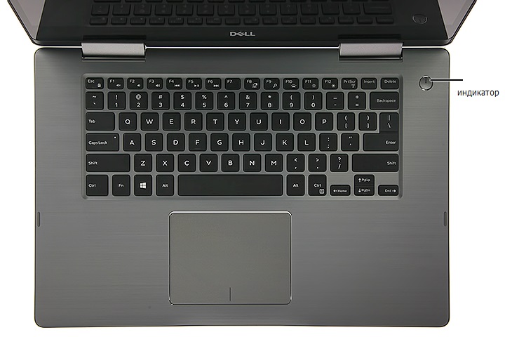
Коды индикатора кнопки питания
Диагностические индикаторы дают очень много информации о состоянии системы
, также в компьютере поддерживаются стандартные состояния
индикаторов питания
. Состояния индикаторов питания приведены в следующей таблице.
Кодовые сигналы
Если во время выполнения процедуры
POST монитор не удается отобразить сообщения об ошибках, компьютер может испускать серию звуковых
сигналов
, идентифицирующих неполадку. Такие сигналы полезны при определении неисправных компонентов или узлов. В приведенной ниже таблице
перечисляются кодовые сигналы
, которые могут генерироваться во время выполнения процедуры POST. Большинство кодовых сигналов указывает на
неустранимые ошибки
, которые не позволяют компьютеру завершить процедуру загрузки без устранения указанного состояния.
Extended Test
(Расширенная проверка)
Полная проверка устройств
. Данная проверка обычно занимает не менее 1 часа, при этом периодически следует
отвечать на определенные вопросы
.
Custom Test
(Настраиваемая
проверка
)
Проверка конкретного устройства
. Можно настроить параметры проверок, которые вы хотите выполнить.
Symptom Tree (Дерево
симптомов
)
Выводится список наиболее часто встречающихся внешних проявлений неполадок
, что позволяет вам выбрать проверку
на основании внешнего проявления возникшей неполадки
.
Вкладка
Функция
Results (Результаты) Результаты проверки и выявленные ошибки.
Errors (Ошибки)
Выявленные ошибки
, их коды и описание проблемы.
Help (Справка)
Описание проверки и возможных требований для ее запуска
.
Configuration
(Конфигурация)
Описание аппаратной конфигурации выбранного устройства
.
Программа
Dell Diagnostics получает информацию о конфигурации всех устройств из программы настройки системы, памяти и
различных внутренних проверок
, а затем отображает ее как список устройств в левой части экрана. В списке устройств могут
отсутствовать имена некоторых установленных компонентов компьютера или подключенных к нему устройств
.
Parameters
(Параметры)
Настройка проверки путем изменения ее параметров
.
Состояние индикатора
питания
Описание
Не горит
.
Питание отключено
, индикатор не горит.
Мигает желтым
светом
Начальное состояние при включении питания
.
Указывает на наличие питания в системе при неактивности сигнала
POWER_GOOD.
Если индикатор жесткого диска не светится
, возможно, необходимо заменить блок питания.
Если светодиод жесткого диска горит
, возможно, неисправен регулятор на плате или VRM. Дополнительные сведения
можно получить от диагностических индикаторов
.
Горит желтым цветом
Второе состояние индикатора при включении питания
. Указывает на наличие сигнала POWER_GOOD. Возможно, питание в
норме
. Дополнительные сведения можно получить от диагностических индикаторов.
Мигает зеленым
светом
Система в состоянии низкого энергопотребления
S1 или S3. Для определения состояния системы посмотрите на
диагностические индикаторы
.
Горит зеленым
Система в состоянии
S0, обычном состоянии для питания функционирующей машины.
BIOS переводит индикатор в это состояние, чтобы указать на начало считывания кодов операций в оперативную память.
Код
Причина
1-1-2
Сбой регистра микропроцессора
1-1-3
Ошибка чтения
/записи энергонезависимого ОЗУ
1-1-4
Ошибка контрольной суммы ПЗУ
BIOS
1-2-1
Ошибка программируемого таймера временных интервалов
1-2-2
Ошибка инициализации прямого доступа к памяти
1-2-3
Ошибка чтения
/записи регистра страницы прямого доступа к памяти
Компания Dell в своей продукции достаточно давно использует систему звуковых и световых кодировок неисправностей. Это помогает пользователю и сервисным центрам определить примерную причину остановки запуска. И соответственно значительно упростить общую диагностику в случаях отсутствия изображения на дисплее.
Звуковые сигналы
Ниже приведен список из повторяющихся звуковых кодов ошибок. Цифра в списке означает количество звуковых сигналов через короткий интервал времени. Сигнал повторяется, что удобно при подсчете.
- BIOS ROM checksum in progress or failure System board failure, covers BIOS corruption or ROM errors. Неисправна материнская плата, возможно повреждение BIOS или сбой ПЗУ.
- No Memory (RAM) detected Memory or Memory slot failure. Не обнаружена оперативная память (ОЗУ).
- Сhipset Error (North and South bridge error, DMA/IMR/Timer error). Time-Of-Day Clock test failure. Gate A20 failure. Super I/O chip failure. Keyboard controller test failure. System board failure. Неисправна материнская плата или компоненты системной логики (процессор, северный мост, южный мост, хаб, мультиконтроллер IO).
- Memory read / write failure Memory failure. Ошибки при процедурах чтения и записи в модуль ОЗУ.
- Real Time Clock (RTC) power fail. CMOS battery failure. Сбой питания часов реального времени. Возможно отсутствует или разряжена батарейка CMOS.
- Video BIOS test failure. Video subsystem failure. Сбой видеопроцессора или набора микросхем.
- CPU. Cache test failure. Processor failure. Сбой центрального процессора.
- LCD. LCD failure. Сбой ЖК-дисплея или ошибка чтения EDID.
Световые сигналы.
Диагностические индикаторы ноутбуков (с 2006 по 2014 гг.)
В системах, выпущенных в этот период времени, индикаторы используются только для отображения состояния аккумулятора и жесткого диска. Диагностические коды ошибок сообщаются путем звуковых сигналов на основные динамики ноутбука.
| Белый | Адаптер питания подключен и аккумулятор заряжается. |
| Желтый | Низкий или критически низкий заряд аккумулятора. |
| Не горит | Компьютер работает от сети и аккумулятор заряжен. Если работает от аккумулятора, это означает что уровень заряда аккумулятора более 10%. |
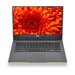
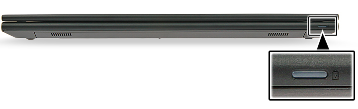
Диагностические индикаторы ноутбуков серии Inspiron, XPS, Vostro (с 2014 года и по настоящее время).
В новых сериях компьютеров не используются звуковые коды. Для сообщения ошибки, используются различные схемы мигания и цвета подсветки кнопки питания. И других элементов в зависимости от конкретной модели ноутбука.
Мигающие индикаторы определяют 2 набора чисел. Они представлены первой группой (мигает желтый индикатор) и второй группой (мигает белый индикатор).
- Первая группа: индикатор аккумулятора мигает желтым светом до 9 раз, затем приостанавливается на 1,5 секунды перед запуском второй группы.
- Вторая группа: индикатор аккумулятора мигает белым светом до 9 раз, затем приостанавливается на 3 секунды перед повторным запуском первой группы.
Например: если память не обнаружена (2, 3), индикатор аккумулятора мигает два раза желтым светом, приостанавливается, а затем мигает три раза белым светом, приостанавливается и т. д. Этот шаблон продолжается до отключения питания системы.
| Желтый | Белый | Описание кода |
| 2 | 1 | Ошибка центрального процессора. |
| 2 | 2 | Сбой запуска BIOS. |
| 2 | 3 | Отсутствие ОЗУ. |
| 2 | 4 | Ошибки чтениязаписи ОЗУ. |
| 2 | 5 | Установлена недопустимая память. |
| 2 | 6 | Ошибка системной платы, набора микросхем. |
| 2 | 7 | Cбой чтения EDID дисплея. |
| 3 | 1 | Сбой питания RTC. |
| 3 | 2 | Ошибка PCI или видеопроцессора. |
| 3 | 3 | Образ для восстановления BIOS не найден. |
| 3 | 4 | Образ для восстановления BIOS не подходит. |
В некоторых сериях Dell Vostro (с 2010 — 2015 года)
Использовался одноцветный световой, диагностический индикатор. Который также выдавал код. В середине повторяющегося кода вставлена 3-секундная пауза.
Например: если не обнаружены модули памяти, индикатор кнопки питания мигает два раза, затем делает паузу, мигает два раза, делает паузу и т. д. Этот процесс продолжается до выключения питания системы.
Расшифровка количества миганий одноцветного светового индикатора соответствует таблице звуковых сигналов представленной в начале статьи.
Заключение.
В заключении хочу сказать что основная информация взята с официального сайта компании dell. Старался для себя, ну и всех Вас. Для более удобного поиска и использования в процессе ремонта. Спасибо за уделенное моей статье внимание, ставьте лайки, делайте репосты с указанием автора. Можете подписаться на группу в вконтакте для получения ссылок на новые посты. Удачи!
Enhanced Pre-Boot System Assessment (ePSA)
diagnostics
The ePSA diagnostics (also known as system diagnostics) performs a complete check of your hardware. The ePSA is embedded with the
BIOS and is launched by the BIOS internally. The embedded system diagnostics provides a set of options for particular devices or device
groups allowing you to:
•
Run tests automatically or in an interactive mode
•
Repeat tests
•
Display or save test results
•
Run thorough tests to introduce additional test options to provide extra information about the failed device(s)
•
View status messages that inform you if tests are completed successfully
•
View error messages that inform you of problems encountered during testing
CAUTION:
Use the system diagnostics to test only your computer. Using this program with other computers may cause invalid
results or error messages.
NOTE:
Some tests for specific devices require user interaction. Always ensure that you are present at the computer terminal
when the diagnostic tests are performed.
NOTE:
Regular ePSA’s run for about 5 to 10 minutes, however, the extended test takes about three and half hours with only 8GB
of ram in the system.
Running the ePSA diagnostics
1
Power-on the computer.
2
As the computer boots, press the F12 key as the Dell logo appears.
3
On the boot menu screen, select the Diagnostics option.
The Enhanced Pre-boot System Assessment window is displayed, listing all devices detected in the computer. The diagnostics starts
running the tests on all the detected devices.
4
To run a diagnostic test on a specific device, press Esc and click Yes to stop the diagnostic test.
5
Select the device from the left pane and click Run Tests.
6
If there are any issues, error codes are displayed.
Note the error code and contact Dell.
LCD built in self test (BIST)
All-in-One (AIO) systems supports LCD BIST similar to any other Dell systems that have BIST test implemented. It allows the user to isolate
the LCD during troubleshooting to determine which sub-system is at fault. The main difference is the lack of an integrated keyboard scan
controller in the AIO. When BIST is initiated, an internal generated pattern from the LCD will be emitted for user’s observation. This pattern
will go by sequence through this pattern. Black-White-Red-Green-Blue or a White-Black-Red-Green-Blue where each pattern is emitted for
2 to 3 seconds. The following images displays the pattern of the colors on the LCD.
62
Troubleshooting
6