
IC100C Series
33. A
C
E
LARM
ODE AND
VENTS
Cod
Meaning
Cause / Origin
P1
Pb1 probe alarm
Missing,
probe or resistance
exceeding value
P2
Pb2 probe alarm
Missing,
probe or resistance
exceeding value
P3
Pb3 probe alarm
Missing,
probe or resistance
/current exceeding
value
P4
Pb4 probe alarm
Missing,
probe or resistance
exceeding value
A01
High pressure
Digital input for
switch alarm
high
activated
A02
Low
pressure
Digital input for low
switch alarm
pressure activated
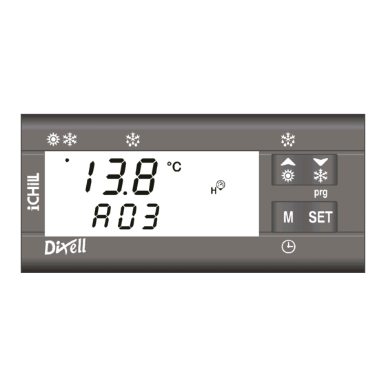
A03
Low
temperature
Digital input active
alarm
of
the
if CF01=0,1 and
supplied
Pb1<
temperature
AR05 seconds.
A04
Low
temperature
Digital input active
alarm of the outlet
if CF01=0,1 and
air
from
Pb2<
evaporator.
AR05 seconds
A05
High temperature
Digital input active
High pressure
Pb3 o Pb4 > AL11
A06
Low temperature
Digital input active
Low pressure
Pb3 o Pb4 < AL14
1592015000 Manual IC100C Series
Instrument behaviour
faulty
Open collector / alarm relay ON
Buzzer ON
General alarm icon lighted
Alarm code on display
faulty
Open collector / alarm relay ON
Buzzer ON
General alarm icon lighted
Alarm code on display
faulty
Open collector / alarm relay ON
Buzzer ON
General alarm icon lighted
Alarm code on display
faulty
Open collector / alarm relay ON
Buzzer ON
General alarm icon lighted
Alarm code on display
Open collector / alarm relay ON
pressure
Buzzer ON
High pressure icon lighted
Alarm code on display
Open collector / alarm relay ON
Buzzer ON
Low pressure icon lighted
Alarm code on display
Open collector / alarm relay ON
Buzzer ON
AR03
for
General alarm icon lighted
Alarm code on display
Open collector / alarm relay ON
Buzzer ON
AR03
for
General alarm icon lighted
Alarm code on display
Open collector / alarm relay ON
Buzzer ON
High alarm icon lighted
Alarm code on display
Open collector / alarm relay ON
Buzzer ON
Low alarm icon lighted
Alarm code on display
28/05/03
PRELIMINARY
Reset
Automatic if the probe value
recovers
Automatic if the probe value
recover
Automatic if the probe value
recovers
Automatic if the probe value
recovers
Manual:
after the alarm event expires,
proceed with manual reset.
Automatic.
It turns to manual after AL02
events in 1 hour.
Manual:
after the alarm event expires,
proceed with manual reset.
Automatic:
when Pb1 value increases over
AR03+AR04 value.
Automatic.
It turns to manual after Ar06
events in 1 hour.
Manual:
the event expires if Pb2 >
(AR03+ AR04), then proceed
with manual reset.
Manual:
the event expires if Pb3 or Pb4
< (AL11-AL12), then proceed
with manual reset.
Automatic.
It turns to manual after AL06
events in 1 hour.
Manual:
the event expires if Pb3 or Pb4
> (AL14+AL15), then proceed
with manual reset.
Page 14 di 38

-
Contents
-
Table of Contents
-
Bookmarks
Quick Links
IC200L Series
User manual
dIXEL
Related Manuals for dixell ichill IC260L
Summary of Contents for dixell ichill IC260L
-
Page 1
IC200L Series User manual dIXEL… -
Page 2: Table Of Contents
INDEX GENERAL ADVICE GENERAL FEATURES MAIN FUNCTION IC200 L TABLE OF THE FEATURES USER INTERFACE FUNCTION OF THE LEDS OF THE KEY BUTTONS USE OF THE LED ON THE MODELS VI620 — VI620S REMOTE PANELS USE OF THE LED ON THE MODELS VI820 — VI820S REMOTE PANELS KEY FUNCTION KEY COMBINANTION LED AND ICONS…
-
Page 3
12.3 CHILLER – HEAT PUMP FUNCTIONING MODE 12.4 KEYBOARD SELECTION 12.5 ANALOG INPUT SELECTION UNIT START- STOP 13.1 START – STOP AND STAND- BY FROM KEYBOARD 13.2 UNIT START- STOP FROM DIGITAL INPUT DISPLAY LAYOUT 14.1 HOW TO SHOW THE MEASUREMENT LIST. 14.2 SHOW THE CIRCUIT 1 OR 2 CUSTOM DISPLAY… -
Page 4
23.3 THERMOREGULATION OF THE SUPPORT HEATERS FOR AIR/AIR UNIT 23.4 CONDENSER ANTI-FREEZE HEATERS REGULATION 23.5 THE THERMOREGULATION OF THE ANTI-FREEZE HEATERS OF THE CONDENSER/RECOVERY 23.6 GRAPH OF THE ANTI-FREEZE- INTEGRATION HEATING — BOILER HEATER RELAYS 23.7 BOILER THERMOREGULATION(ANTIFREEZE), BOILER FUNCTION ANTI — FREEZE ALARM AND HEATERS REGULATION THROUGH DIGITAL INPUT THERMOREGULATION AND COMPRESSORS ROTATION… -
Page 5
DEFROST CYCLE 38.1 FORCED DEFROST 38.2 COMBINED DEFROST 38.3 MANUAL DEFROST 38.4 DEFROST START CONDITION WITH TWO CIRCUIT UNIT 38.5 END OF THE DEFROST IN A TWO CIRCUITS WITH ONE CONDENSING FAN CONTROL UNIT 38.6 AUTOMATIC DEFROST PROCEDURE 38.7 OTHER INFORMATION ABOUT THE DEFROST 38.8 DEFROST PARAMETER DESCRIPTION RECOVERY… -
Page 6: Electrical Connections
45.2 PLEXIGLASS PROTECTION BOTTOM OPEN 45.3 PLEXIGLASS PROTECTION TOP OPEN 45.4 METAL FRONT FRAME 45.5 VERTICAL BOARDS VI620 – VI820 PANEL CUT-OUT ELECTRICAL CONNECTIONS ACCESSORIES 47.1 MONOPHASE FAN CONTROL: 230VAC AND CUT PHASE CONTROL 47.2 INVERTER: MICROFAN 380VAC UP TO 4KW OR 8KW 47.3 TRANSFORMER TECHNICAL DATA…
-
Page 8: General Advice
· The instrument must not be opened. • · In case of failure or faulty operation send the instrument back to the • distributor or to “Dixell s.r.l.” (see address) with a detailed description of • the fault. • · Consider the maximum current which can be applied to each relay (see •…
-
Page 9: General Features
1592015300 User manual iCHILL 200 L GB r1.3 09/09/2005 GENERAL FEATURES iCHILL IC200L is an electronic controller for chiller unit applications having one or two circuits: • Air/air • Air/water • Water/water • Motocondensing Additional features : • Heat pump with gas reversibility •…
-
Page 10
Internal Data logger up to 100 events Supervisor / tele assistance/ monitoring • TTL output for XJ485 interface (Mod #Bus protocol) for XWEB300 / XWEB3000 Dixell monitoring system for local and remote control Up to 2 remote terminals with display read-out customizable •… -
Page 11: Ic200 L Table Of The Features
1592015300 User manual iCHILL 200 L GB r1.3 09/09/2005 3 IC200 L TABLE OF THE FEATURES FEATURES IC260L IC261L IC280L IC281L CHILLER WITH HEAT PUMP, CHILLER WITH HEAT PUMP FREE COOLING AND HEATING RECOVERY FRONTPANEL KEY BUTTONS OUTPUT RELAYS DIGITAL INPUTS configurable configurable configurable…
-
Page 12: User Interface
1592015300 User manual iCHILL 200 L GB r1.3 09/09/2005 4 USER INTERFACE 4.1 F KEY BUTTONS UNCTION OF THE S OF THE Use of the led on the IC260L / IC261L models Use of the led on the IC260L / IC261L metal models…
-
Page 13
1592015300 User manual iCHILL 200 L GB r1.3 09/09/2005 Use of the led on the models IC280L / IC281L Use of the led on the metal models IC280L / IC281L Pg.12/105… -
Page 14
1592015300 User manual iCHILL 200 L GB r1.3 09/09/2005 4.2 U VI620 — VI620S SE OF THE LED ON THE MODELS REMOTE PANELS 4.3 U VI820 — VI820S SE OF THE LED ON THE MODELS REMOTE PANELS… -
Page 15: Key Function
1592015300 User manual iCHILL 200 L GB r1.3 09/09/2005 4.4 KEY FUNCTION ACTION FUNCTION Push and release Show chiller set point SetC and heat pump SetH In chiller or heat pump if the Energy saving or the Dynamic Push once setpoint are enabled it shows the real setpoint Setr, the led is blinking.
-
Page 16: Key Combinantion
1592015300 User manual iCHILL 200 L GB r1.3 09/09/2005 4.5 KEY COMBINANTION ACTION FUNCTION Push for 3 seconds together Enter the programming In Pr3 level: push SET and the push Select the parameter level visibility Pr1 / Pr2 / Pr3 DOWN key Push once together Exit the programming…
-
Page 17
1592015300 User manual iCHILL 200 L GB r1.3 09/09/2005 4.7 D ISPLAY AND CONS ICON MEANING / FUNCTIONNING Celsius degrees: ON for temperature measurements of probe values or parameters Fahrenheit degrees: ON for temperature measurements of probe values or parameters Bar: ON for pressure measurements of probe values, setpoint or parameters Psi: ON for pressure measurements of probe values, setpoint or parameters ON = compressor 1 active… -
Page 18: Remote Terminal
1592015300 User manual iCHILL 200 L GB r1.3 09/09/2005 4.8 M EANING UNCTIONNING OF THE BOTTOM DISPLAY LED Led # 1 – 2 (With RTC) If the bottom display shows the RTC the 1 and 2 leds are blinking. Led # 1 – 2 In function Menu During the time counting to the next defrost for one or both circuits the led 1 and 2 are blinking.
-
Page 19: Wiring Connections
1592015300 User manual iCHILL 200 L GB r1.3 09/09/2005 7 WIRING CONNECTIONS 7.1 H IC260L — IC280L M ARDWARE ESOURCES FOR ODELS 10 digital outputs (relays) 18 digital inputs (free of voltage) 10 analogue inputs: NTC probes or through configuration 6 NTC / PTC and 4 pressure transducer 4÷20mA or ratio-metric 0÷ 5.0Volt 6 modulating outputs 1 output for remote panel (max 2 remote panels) 1 TTL output for “Hot Key 64”…
-
Page 20
1592015300 User manual iCHILL 200 L GB r1.3 09/09/2005 7.3 A NTC – PTC P NALOG NPUTS ROBES PbC = Common terminal 7.4 D IGITAL NPUTS GND = Common terminal 7.5 A 30 (4 ÷ 20 NALOG NPUT FOR RESSURE RANSDUCER SIGNAL Using 4÷20mA pressure transducer set the Parameter CF07 = 0 / 1… -
Page 21
1592015300 User manual iCHILL 200 L GB r1.3 09/09/2005 7.6 A 30 (0 ÷ 5V NALOG NPUT FOR RESSURE ATIOMETRIC RANSDUCER SIGNAL Using 5V ratio-metric pressure transducer set the Parameter CF07 = 2 / 3 7.7 PWM O UTPUT FOR ONDENSING PEED ONTROL… -
Page 22
With only one condensing circuit configured, the Out1 / Out2 outputs work together giving the same signal. With the two 0 – 10V outputs the iCHILL can drive a mono-phase or three-phase controllers (such as the Dixell inverter models XV340GS) up to 8KW. -
Page 23
1592015300 User manual iCHILL 200 L GB r1.3 09/09/2005 7.10 P 0 ÷ 10V ROPORTIONAL OUTPUTS DUMPER CONTROL GND = common 7.11 P ROPORTIONAL OUTPUTS CONFIGURED FOR AUX RELAY CONTROL GND = common By parameter programming is possible to connect a 12 volt, 40mA relay. Pg.22/105… -
Page 24
1592015300 User manual iCHILL 200 L GB r1.3 09/09/2005 7.12 H 64 C ONNECTION The programming HOT KEY 64 allows to upload or download a copy of the parameters of the instrument (see HOT KEY paragraph). 7.13 XJ485 C ONNECTION The XJ485 interface is a converter between the RS485 and the TTL connector output. -
Page 25
1592015300 User manual iCHILL 200 L GB r1.3 09/09/2005 7.14 R VI620 – VI820 EMOTE ANELS The instrument receives up to two remote panels. Using the remote panels provided with the ambient NTC probe the display measurement, and the control can be managed directly by this probe. Use shielded cable for the connection up to 150mt maximum. In case of communication failure the upper display shows “noL”… -
Page 26: Digital Inputs
1592015300 User manual iCHILL 200 L GB r1.3 09/09/2005 23. Temperature probe NTC for auxiliary output #2 24. Temperature probe NTC for condensing circuit #1 25. Temperature probe NTC for condensing circuit #22 After the number 25 the display configuration can be selected from o 1 to c62 that allows to set an analogue input as digital input (see polarity of the digital input/outputs).
-
Page 27
1592015300 User manual iCHILL 200 L GB r1.3 09/09/2005 26. Water pump overload of evaporator 1 27. Water support pump overload of evaporator 28. Water pump overload of condenser 1 29. Water support pump overload of condenser 30. Recovery request for circuit 1 31. -
Page 28
1592015300 User manual iCHILL 200 L GB r1.3 09/09/2005 Star-delta start: relay linea #2 compressor #1 31. Star centre of the Star-delta start of the compressor 1# 32. Capacity step valve #1 compressor #1 33. Capacity step valve #2 compressor #1 34. -
Page 29: Table Of The Parameters
1592015300 User manual iCHILL 200 L GB r1.3 09/09/2005 9 TABLE OF THE PARAMETERS MENU SELECTION Description Label Shows all the parameters Shows only the Thermoregulation parameters Shows only the Configuration parameters Shows only the Dynamic Setpoint parameters Shows only the Energy Saving, RTC parameters Shows only the compressor parameters Shows only the Auxiliary Output parameters Shows only the Fan Control parameters…
-
Page 30
1592015300 User manual iCHILL 200 L GB r1.3 09/09/2005 dP 1 Default read-out of the top display dP 2 Default read-out of the bottom display dP 3 Default display read-out configuration top / bottom 0= Configurable 1= Top display: Evaporator IN, Bottom display: Evaporator OUT 2= Top display: Condenser IN, Bottom display: Condenser OUT 3=Top display:… -
Page 31
1592015300 User manual iCHILL 200 L GB r1.3 09/09/2005 CF 7 Pressure or temperature analogue input functioning = Temperature / pressure NTC – 4÷20 mA : The condensing temperature is controlled with NTC probe while for the evaporating pressures of the circuits 1 and 2 and the pressure probe configured as auxiliary output 1 and 2 are controlled with 4÷20mA transducers. -
Page 32
1592015300 User manual iCHILL 200 L GB r1.3 09/09/2005 CF 26 PB9 Offset -12.0 12.0 °C °F CF 27 PB10 Offset -12.0 12.0 °C °F CF 28 Pressure value at 4mA or 0.5 Vdc of the PB3 transducer 50.0 CF 29 Pressure value at 20mA or 5 Vdc of the PB3 transducer 50.0 CF 30… -
Page 33
1592015300 User manual iCHILL 200 L GB r1.3 09/09/2005 CF 71 Proportional output 2 0= Not enabled 1= Free cooling Dumper / Mixing valve 2= 3-way valve for hot water 3= Dumper for air change 4= auxiliary output Relay driver ON / OFF CF 72 Proportional output 3 0= Not enabled… -
Page 34
1592015300 User manual iCHILL 200 L GB r1.3 09/09/2005 Sd 3 External air setpoint in chiller mode -30.0 70.0 °C °F Sd 4 External air setpoint in heat pump mode 70.0 °C °F Sd 5 External air differential in chiller mode -30.0 30.0 °C… -
Page 35
1592015300 User manual iCHILL 200 L GB r1.3 09/09/2005 CO 8 Relay ON time of the Solenoid valve Intermittent for screw compressor, with 0 the function is not enabled. CO 9 Relay OFF time of the Solenoid valve Intermittent for screw compressor Compressor start-up CO 10 Kind of compressor start-up… -
Page 36
1592015300 User manual iCHILL 200 L GB r1.3 09/09/2005 CO 36 Pump down operating mode (See pump down ON/OFF function) 0= Not enabled 1= Unit off with pump–down, unit on without pump–down 2= Unit off with pump–down, unit on with pump–down 3= Chiller mode off with pump–down, chiller mode on without pump–down 4= Chiller mode off with pump–down, chiller mode on with pump–down CO 37… -
Page 37
1592015300 User manual iCHILL 200 L GB r1.3 09/09/2005 US 7 Auxiliary setpoint 2 (See graph and auxiliary relay functions) -30.0 70.0 °C °F 50.0 US 8 Auxiliary differential 1 (See graph and auxiliary relay functions) 25.0 °C °F 14.0 Password Password Password… -
Page 38
1592015300 User manual iCHILL 200 L GB r1.3 09/09/2005 FA 16 Minimum speed for condenser fan in Heat Pump mode. To set the minimum fan speed percentage value (30..100%), it is related to the fan power supply. FA 17 Maximum speed for condenser fan in Heat Pump mode. To set the maximum fan speed percentage value (30..100%), it is related to the fan power supply. -
Page 39
1592015300 User manual iCHILL 200 L GB r1.3 09/09/2005 Ar 6 Antifreeze alarm probe / heaters / appoggio in Chiller mode. 0= Not enabled 1= Evaporator inlet 2= Evaporator outlet 1 and 2 3= Evaporator outlet 1 and 2 and common outlet Ar 7 Antifreeze alarm probe / heaters / support heaters in HP mode. -
Page 40
1592015300 User manual iCHILL 200 L GB r1.3 09/09/2005 dF 11 Temperature setpoint for combined defrost end of the 1 circuit. -30.0 70.0 °C °F dF 12 Temperature setpoint for combined defrost of the 2 circuit after parameter -30.0 70.0 °C DF10 counting. -
Page 41
1592015300 User manual iCHILL 200 L GB r1.3 09/09/2005 Password Password Alarms Parameters Description m. u. Resolution Low alarm AL 1 Low pressure alarm delay from analog and digital input AL 2 Low pressure alarm delay from digital input after compressor stop if the low pressure switch is used for the pump down. -
Page 42
1592015300 User manual iCHILL 200 L GB r1.3 09/09/2005 AL 22 Maximum number of pump down alarm events per hour in start-up condition. After this number the alarm is logged, displayed and signalled with alarm relay + buzzer. Always manual reset if AL22 = 0 Always automatic reset if AL22 =16 From automatic to manual reset if AL21 =1..15 and parameter AL23 config. -
Page 43
1592015300 User manual iCHILL 200 L GB r1.3 09/09/2005 AL 41 Number of compressor high discharge temperature events per hour to determine the alarm reset condition: Always manual reset if AL41 = 0 Always automatic reset if AL41 =16 From automatic to manual if AL41 = 1..15 AL 42 Maximum number of generic alarm events (each event stop the regulation) before turning the alarm from automatic to manual:… -
Page 44
1592015300 User manual iCHILL 200 L GB r1.3 09/09/2005 • The parameter can be showed but not changed. 11.2 E 1 — P 2 — P NTER THE PROGRAMMING LEVELS Pr1 LEVEL: Push SET + DOWN together for 3 seconds, the top display shows the PAS label and the bottom display shows the Pr1 label. The leds cir1/cir2 are blinking (up and down leds) to inform that you now are in PR1 programming level. -
Page 45
1592015300 User manual iCHILL 200 L GB r1.3 09/09/2005 Parameter status, leds and bottom display in Pr1 • If the selected parameter can not be changed the leds 1 and 2 are blinking. • In Pr1 level the user can not see and change any parameter of Pr2 and Pr3. •… -
Page 46
1592015300 User manual iCHILL 200 L GB r1.3 09/09/2005 • Leds 1 / 2 are blinking: the parameter can not be changed. • All the leds are off: the parameter is available only in Pr3. • Led 4 on: the parameter can be changed also in Pr2. •… -
Page 47: Selection And Start Of The Running Mode
1592015300 User manual iCHILL 200 L GB r1.3 09/09/2005 Proportional output configured as ON/OFF Analogue input configured as digital input have a different parameter description that allows to configure the operating mode and the corresponding polarity. Example of programming: The bottom display shows the parameter label (CF36) Digital input ID1 configuration; Note that the top display shows “c”…
-
Page 48: Unit Start- Stop
1592015300 User manual iCHILL 200 L GB r1.3 09/09/2005 12.3 C – H HILLER UMP FUNCTIONING MODE IT IS DEFINED BY THE PARAMETER CF78. 12.4 K EYBOARD SELECTION CF78 = 0: pushing key the unit starts in chiller, pushing key the unit starts in heat pump CF78 = 1: pushing key the unit starts in heat pump, pushing key the unit starts in chiller…
-
Page 49: Display Layout
1592015300 User manual iCHILL 200 L GB r1.3 09/09/2005 14 DISPLAY LAYOUT As default, In normal condition, the display shows the circuit 1 information. The displayed circuit is indicated from the corresponding led Cir1 on (UP key), or Cir2 (circuit 2, DOWN key). 14.1 H OW TO SHOW THE MEASUREMENT LIST With the led Cir1 on, push UP or Down keys to display the labels of the information of the circuit 1.
-
Page 50
1592015300 User manual iCHILL 200 L GB r1.3 09/09/2005 Select the dP01 parameter into the range 0..14 descripted here below: PARAMETER CORRESPONDING DESCRIPTION VALUE LABEL dP01=0 No display read out No label dP01=1 NTC temperature probe of the evaporator water inlet Out1 circuit 1 dP01=2 NTC temperature probe of the evaporator water outlet 1 and 2… -
Page 51
1592015300 User manual iCHILL 200 L GB r1.3 09/09/2005 15.2 D EFAULT READ OUT OF THE BOTTOM DISPLAY To set the default value displayed on the bottom display: Set the parameter dP03 = 0, it means configurable; Select the dP02 parameter into the range 0..17 descripted here below: PARAMETER CORRESPONDING DESCRIPTION… -
Page 52: Display Information
1592015300 User manual iCHILL 200 L GB r1.3 09/09/2005 Bottom display: circuit 2: • Evaporator 2 water outlet, with the label OuT2. Par. dP03 = 2 Top display of the circuit 1: • Condenser 1 water inlet temperature with the label CIn1 Bottom display of the circuit 1 •…
-
Page 53: Function Menu » M» Key
1592015300 User manual iCHILL 200 L GB r1.3 09/09/2005 16.4 D ISPLAY IN EMOTE From digital input configured as remote ON/OFF: the active input sets the unit in OFF (even when the unit is a motocondensing unit). The top display shows “OFF ”, the led of the decimal point is blinking. 16.5 D ISPLAY IN OTOCONDENSING CONFIGURATION…
-
Page 54
1592015300 User manual iCHILL 200 L GB r1.3 09/09/2005 Repeat operation 1 – 5 to reset the other alarms. 17.3 C OMPRESSOR OVERLOAD PASSWORD The default value is 0 to change this value enter Pr3 level under the AL parameter family 17.4 A LARM LOG LIST ALOG FUNCTION TO SEE THE ALARM LOG… -
Page 55
1592015300 User manual iCHILL 200 L GB r1.3 09/09/2005 To exit the COEn function push MENU key or wait the timeout. 17.10 R OUT OF A COMPRESSOR OT ENABLED During the normal running condition a disabled compressor is displayed with a blinking label alternated with the measurement value of the display. -
Page 56
1592015300 User manual iCHILL 200 L GB r1.3 09/09/2005 17.16 R OUT OF THE ROPORTIONAL UTPUT PERCENTAGE OF THE CONDENSER FAN CONTROL The proportional outputs of the two circuits, that control the fan speed, can be showed in the menu function. Cond FUNCTION selects the proportional output 1 and 2. -
Page 57: Energy Saving
1592015300 User manual iCHILL 200 L GB r1.3 09/09/2005 FUNCTION trEM to show the temperature of the remote panels Identification label trEM. trE1 value of the NTC probe of the remote #1 trE2 value of the NTC probe of the remote #2 Select with UP or DOWN the trEM function Push SET the trE1 or trE2 label is shown on the bottom display, the top display shows the probe value.
-
Page 58: Dynamic Setpoint
1592015300 User manual iCHILL 200 L GB r1.3 09/09/2005 Energy saving or unit ON/OFF where: X with range 0..7 represents the energy saving with RTC and X Y where: Y with range 0..7 represents the unit on/off Example of a daily programming: Monday Enater parameter programming In the ES parameter family, select the parameter ES07, the top display shows 0 — 0…
-
Page 59
1592015300 User manual iCHILL 200 L GB r1.3 09/09/2005 • In chiller mode the parameter Sd01 is not equal to 0. • In heat pump mode the parameter Sd02 is not equal to 0. • a 4÷20mA analogue input is configured as dynamic setpoint control or a NTC analogue input is configured as external air temperature for dynamic setpoint control. -
Page 60: Auxiliary Relays
1592015300 User manual iCHILL 200 L GB r1.3 09/09/2005 20 AUXILIARY RELAYS The auxiliary relays can be configured to manage two independent, from heat pump or chiller mode, output controls. Each output can be managed with a dedicated temperature or pressure probe input ( NTC probe, 4..20mA or 0..5V transducers) or with the common available temperature or pressure configurable inputs.
-
Page 61: Selection Of The Kind Of Thermoregulation
1592015300 User manual iCHILL 200 L GB r1.3 09/09/2005 Par. ST04 Heat pump setpoint It allows to set the Heat pump working temperature within the range ST05..ST06. Par. ST05 Minimum setpoint limit in heat pump. The user can not program a setpoint value lower than ST05, the range is –30 °C..ST04. Par.
-
Page 62: Graph Neutral Zone Compressor Control
1592015300 User manual iCHILL 200 L GB r1.3 09/09/2005 22.2 G RAPH OF THE COMPRESSOR THERMOREGULATION N HEAT PUMP 22.3 GRAPH NEUTRAL ZONE COMPRESSOR CONTROL Not yet available on this version Compressor regulation in chiller Compressor regulation in heat pump 22.4 GRAPH PROPORTIONAL INTEGRAL COMPRESSOR REGULATION CONTROL Not yet available on this version Compressor regulation in chiller…
-
Page 63
1592015300 User manual iCHILL 200 L GB r1.3 09/09/2005 Par. Ar07 = 3: the thermoregulation, the anti-freeze alarm and the relay outputs for heaters circuit 1 and 2 is controlled throughout the NTC probes configured as evaporator water outlet circuit #1, circuit #2 and evaporator water common outlet , or if they are all configured, by the first probe that goes below the setpoint. -
Page 64: Anti — Freeze Alarm And Heaters Regulation Through Digital Input
1592015300 User manual iCHILL 200 L GB r1.3 09/09/2005 23.6 G RAPH OF THE ANTI FREEZE INTEGRATION HEATING BOILER HEATER RELAYS 23.7 B ), B OILER THERMOREGULATION ANTIFREEZE OILER FUNCTION To determine the electrical heater control in chiller or heat pump mode because the electrical heaters can be used as anti-freeze or can also be used to integrate or heating the heat pump mode or in particular situation in chiller mode.
-
Page 65: Saturation — Circuit Balancing
1592015300 User manual iCHILL 200 L GB r1.3 09/09/2005 CO14= 0 Sequential. Depending on the thermoregulation: the 1 compressor is turned on, then the 2 and the 3 etc.; then the 3 off, the 2 and then 1st. The first is off only if the 2 and 3 are off.
-
Page 66: Part Winding
1592015300 User manual iCHILL 200 L GB r1.3 09/09/2005 Fig. 1 27.3 D IRECT START UP OF A CAPACITY COMPRESSOR When working with capacity compressors and with full power start-up: the controller turns the solenoid valve on first and then, after 1 second, the compressor motor.
-
Page 67: Capacity Control
1592015300 User manual iCHILL 200 L GB r1.3 09/09/2005 Set Par CF56 = 31. Star-delta centre relay of the compressor #1; 27.8 S ELTA TART OMPRESSOR Each compressor needs three relay outputs: One relay output as Line #1 of the compressor #1 (Relay K1 of the Fig.3). One relay output as Line #2 of the compressor #1 (Relay K3 of the Fig.3).
-
Page 68
1592015300 User manual iCHILL 200 L GB r1.3 09/09/2005 Compr. Compressor ON Compressor ON Compressor ON Compressor ON Out relay Step P 1 ON Step P 1 ON Step P 1 ON Step P 1 OFF Out relay Step P 2 OFF Step P 2 ON Step P 2 ON Step P 2 OFF… -
Page 69: Pump Down
1592015300 User manual iCHILL 200 L GB r1.3 09/09/2005 Having one compressor with 3 partializations, with CO07=2 when the compressor is off the partialization valve is always on, so as, in case of start-up, it allows to have the minimum load. After the compressor is started the valve is on only for CO13 time and it won’t be considered as regulation step.
-
Page 70
1592015300 User manual iCHILL 200 L GB r1.3 09/09/2005 If the thermoregulation is stopped via digital input (as remote off) or from chiller/heat pump keys, during the pump down process the chiller or the heat pump led will blink. When the next thermoregulation restarts the PD solenoid valve turns on and after 1 seconds, if the low pressure switch is not active, the compressors start. -
Page 71: Unloading
1592015300 User manual iCHILL 200 L GB r1.3 09/09/2005 ATTENTION If the pump down function is enabled, during the unit start-up from digital input as pump down pressure switch and also from analogue input as low pressure transducer, the compressor will restart only if both the inputs are satisfied. 29.5 P OWN ALARM DURING COMPRESSORS SWITCHING OFF ACTIVATION…
-
Page 72: Regulation
1592015300 User manual iCHILL 200 L GB r1.3 09/09/2005 30.4 U NLOADING WITH RESSURE ONDENSING TEMPERATURE OR VAPORATING PRESSURE CONTROL The function is always enabled for both the running mode in order to reduce the load and helps the unit to start: in chiller for high temperature of the external air to avoid high pressure alarms, in heat pump for low temperature of external air to avoid the low pressure alarms.
-
Page 73: Water Pump Of The Evaporator / Supply Fan
1592015300 User manual iCHILL 200 L GB r1.3 09/09/2005 ATTENTION The display resolution is 0.1°C until the read-out is 99.9, over 100°C it is 1°C. 32 WATER PUMP OF THE EVAPORATOR / SUPPLY FAN 32.1 WATER PUMP OF THE EVAPORATOR / SUPPLY FAN ( With only one evaporator water pump configured, the parameter CO19 / CO20 values do not affect the water pump functioning itself.
-
Page 74: Hot Start
1592015300 User manual iCHILL 200 L GB r1.3 09/09/2005 Note: During the defrost and when the compressor is off in dripping time the pump is on. 33.3 H TART FA25 Hot start Setpoint Low temperature value of PB2 to stop the supply fan. This function is available only with air / air unit configured as heat pump and allows to run the supply fan only when the air temperature is enough hot.
-
Page 75: Load Maintenance
1592015300 User manual iCHILL 200 L GB r1.3 09/09/2005 36 LOAD MAINTENANCE PARAMETERS CO26..CO31 are the set of the running hour counters of the compressors. They establish, for each load, the number of running hours limit to display a maintenance message. If one of these parameters is equal to 0 the maintenance signalling is disabled but the running hours counter remains active.
-
Page 76: Pwm Output For Fan Control
1592015300 User manual iCHILL 200 L GB r1.3 09/09/2005 37.1 ’ OUTPUT STEP RELE CONDENSER FAN Par FA01 = 2 ON/OFF step regulation N° 1 circuit with 4 step of ventilation Step regulation OUT relè step n° 1 step n° 2 step n°…
-
Page 77
1592015300 User manual iCHILL 200 L GB r1.3 09/09/2005 Pg.76/105… -
Page 78: Defrost Cycle
1592015300 User manual iCHILL 200 L GB r1.3 09/09/2005 37.5 G : ON / OFF RAPH REGULATION OF THE CONDENSER FAN HILLER 37.6 G : ON / OFF RAPH REGULATION OF THE CONDENSER FAN 38 DEFROST CYCLE The defrost cycle starts only if all these steps are determined: CF02=1 heat pump unit.
-
Page 79: Combined Defrost
1592015300 User manual iCHILL 200 L GB r1.3 09/09/2005 The count-down to the defrost cycle starts when the temperature/pressure of the probe, configured as condensing/evaporating circuit 1 or 2 probe, is lower than dF02 parameter. After the dF09 counting the instruments checks the temperature probe value (configured as combined defrost circuit 1 or 2) and if it is lower than dF10 (temperature setpoint to start the defrost of the circuit1) or dF12 (temperature setpoint to start the defrost of the circuit2) the defrost cycle starts otherwise the unit still runs in heat pump mode.
-
Page 80
1592015300 User manual iCHILL 200 L GB r1.3 09/09/2005 The compressors and the steps are turned off ( the compressor/s led is blinking, the defrost led is on) Start the dF07 / 2 (half time) time counting; The valve is activated; Start the dF07 / 2 (half time) time counting. -
Page 81
1592015300 User manual iCHILL 200 L GB r1.3 09/09/2005 After the interval dF09 determined by the defrost request of one of the circuits the other 2 circuits must wait also the time dF06 before defrosting. dF07 Compressor off time before the defrost (the led of the compressor is blinking) After the dF09 delay and before activating the defrost, the compressors are stopped for the dF07 time. -
Page 82: Recovery
1592015300 User manual iCHILL 200 L GB r1.3 09/09/2005 39 RECOVERY The recovery function is Enabled if: 1 Par. rC01 not equal to 0. 2 Chiller running mode. 3 The recovery key is pushed to enable the function and the recovery led is on. 4 The condensing temperature / pressure is lower than set rC06 –rC07 (differential).
-
Page 83: Condenser Temperaure / Pressure Condition To Enable/Disable The Recovery Cycle
1592015300 User manual iCHILL 200 L GB r1.3 09/09/2005 When the system is running with 100% (eg all the three compressor of a circuit are on) of power and the digital input stop the recovery function: after the rC04 time delay (minimum on time of the recovery function when activated) and before turning off the recovery valve, one of the step is turned off for the time set in rC02.
-
Page 84: Messages — Alarm Codes
1592015300 User manual iCHILL 200 L GB r1.3 09/09/2005 40.2 R ECOVERY NABLED If the temperaTure/pressure decreases under the set rC06-rC07 (differential) the recovery cycle, of the circuit detected by that transducer , is anabled again. 40.3 N BOUT ECOVERY NABLED ISABLED To avoid long periodof time with recovery function disabled and the temperature/pressure within the range rC06-rC07, the units starts…
-
Page 85: Atsf: Overload Alarm Of The Supply Fan
1592015300 User manual iCHILL 200 L GB r1.3 09/09/2005 CO16 / CO21=2 Compressor on – pump on The alarm is managed only if one digital input is configured as flow switch, the restart is always automatic, in stand–by or remote OFF ( pump off), it becomes manual after AL16 events per hour.
-
Page 86: Acf1 — Acf2 — Acf3 — Acf4 — Acf5 — Acf6 — Acf7 — Acf8 — Acf9 Configuration Alarm Of The Unit
1592015300 User manual iCHILL 200 L GB r1.3 09/09/2005 41.8 AF OWER SUPPLY FREQUENCY ALARM Label on the display AFr (Line frequency alarm) Origin The power supply frequency is not equal to the Par. CF81 + tolerance Reset Ferquency control parameter adjusted, disabled CF81 = 2, frequency within the tolerance Restart Automatic Icon…
-
Page 87
1592015300 User manual iCHILL 200 L GB r1.3 09/09/2005 ACF6 • The total number of compressor of the 2 circuits ( CF04 + CF05 ) is: √ > 6 √ > 4 with no direct compressor start-up (CO10 ≠ 0) or the number of steps is ≠ 0 (CF06), √… -
Page 88: Alarm Relay And Buzzer
1592015300 User manual iCHILL 200 L GB r1.3 09/09/2005 41.12 A LOCK ALARM ArtC (clock alarm) Label o the display Origin Wrong setting Reset Clock adjusted Restart Manual in function menu Icon Blinking Action Alarm relay + buzzer ON Regulation Loads Not changed Energy saving…
-
Page 89
1592015300 User manual iCHILL 200 L GB r1.3 09/09/2005 Actions Only signalling Loads Not modified 41.17 B1HP — B2HP H RESSURE SWITCH CIRCUIT Label on display b1HP (high pressure switch circuit #1) b2HP (high pressure switch circuit #2) Reason The unit is running and the digital input of the high pressure switch is active Reset Digital input not active Restart… -
Page 90
1592015300 User manual iCHILL 200 L GB r1.3 09/09/2005 Normal conditions, stand-by, remote OFF: when the anti-freeze probe value is lower than AL33 for Origin AL36 seconds. With the anti-freeze digital input is active. When the anti-freeze probe value is higher than AL33 + AL34(differenziale). Reset With digital input ont active Restart… -
Page 91
1592015300 User manual iCHILL 200 L GB r1.3 09/09/2005 41.24 ONDENSER FAN OVERLOAD ALARM Label o the display b1tF (Condenser fan overload alarm of the circuit #1) b2tF (Condenser fan overload alarm of the circuit #2) When the digital input is active Origin When the digital input is not active Reset… -
Page 92
1592015300 User manual iCHILL 200 L GB r1.3 09/09/2005 Action Alarm relay + buzzer ON Compressor involved If AL47=0 or 1: OFF Compressor not involved If AL47=0: it follows its regulation. If AL47=1: OFF ATTENTION The parameter AL47 determines the functioning of the overload alarm of the compressors. If AL47 = 0 single compressor locked when its digital input protection is active, on the display the corresponding alarm message. -
Page 93
1592015300 User manual iCHILL 200 L GB r1.3 09/09/2005 41.33 1PH — 2PH: P OWN STOP ALARM FROM PRESSURE SWITCH OW PRESSURE SWITCH Label on the display b1PH (Pump down stop alarm of the circuit 1) b2PH (Pump down stop alarm of the circuit 2) Origin Pressure switch: if CO36 = 1,2,3,4 and ID not active, the pump down stops because of the timeout CO39. -
Page 94
1592015300 User manual iCHILL 200 L GB r1.3 09/09/2005 41.37 ACP1 — ACP1 C ONDENSER PUMP MINTENANCE ACP1 (Condenser #1 pump maintenance) Label o the display ACP1 (Condenser #2 pump maintenance) Pump running hours > Hour counter setpoint Origin Reset Hour reset in function menu Restart Manual… -
Page 95: Alarm: «A» Type And Corresponding Output Off
1592015300 User manual iCHILL 200 L GB r1.3 09/09/2005 43 TABLE OF THE OUTPUT STATUS IN ALARM CONDITION The alarm codes are made of letters and numbers to define the different typologies:. 43.1 ALARM: “A” TYPE AND CORRESPONDING OUTPUT OFF Alarm Alarm description Compressor…
-
Page 96: Alarm: «A» Type And Corresponding Output Off
1592015300 User manual iCHILL 200 L GB r1.3 09/09/2005 ACF8 Configuration alarm ACF9 Configuration alarm ArtF Faulty clock ArtC Clock error AEUn Unloading signalling from high temp of. evaporator water ALti Low evaporator inlet temperature in air/air unit AEP1 Evaporator #1 water pump maintenance AEP2 Evaporator #2 water pump maintenance ACP1…
-
Page 97: Alarm: «A» Type And Corresponding Compressor Output Off
1592015300 User manual iCHILL 200 L GB r1.3 09/09/2005 43.3 ALARM: “A” TYPE AND CORRESPONDING COMPRESSOR OUTPUT OFF Alarm Alarm description Compressor Compressors not involved Code C(n)HP Compressor(n) high pressure switch C(n)oP Compressor(n) oil pressure switch / Oil level switch C(n)tr Compressor(n) overload C(n)dt…
-
Page 98: Black-Out
1592015300 User manual iCHILL 200 L GB r1.3 09/09/2005 44 BLACK-OUT After the black-out is restored: The instrument resores the same operating mode lost after the supply failure. If active, the defrost is aborted. All the timers and time parameters are reloaded. The manual alarm is not reset.
-
Page 99: Metal Front Frame
1592015300 User manual iCHILL 200 L GB r1.3 09/09/2005 45.4 METAL FRONT FRAME 45.5 V 620 – V ERTICAL BOARDS PANEL CUT The remote terminals are for panel mounting, panel cut-out 72×56 mm, and screwed with two screws. The IP65 can be reached with the gasket RGW-V (optional). WALL MOUNTING: use the vertical V-KIT (black, white and grey) as described in the following scheme: Pg.98/105…
-
Page 100: Electrical Connections
1592015300 User manual iCHILL 200 L GB r1.3 09/09/2005 46 ELECTRICAL CONNECTIONS The instrument is provided with: • 3 removable terminal blocks MOLEX with 0.5 mm wires: 16 / 8 /22 ways for digital / analogue inputs and modulating outputs. •…
-
Page 101: Transformer
NVERTER ICROFAN VAC UP TO KW OR Dixell models XV340GS, power up to 8KW (scheme 2) (Scheme 2) 47.3 TRANSFORMER The standard power supply is 12 volt AC/DC or 24 volt AC/DC (optional) The TF10 trasnformer models: 230/12 Vac , 230 /24 Vac, 110 / 12 Vac, 24 / 12 Vac…
-
Page 102: Technical Data
1592015300 User manual iCHILL 200 L GB r1.3 09/09/2005 48 TECHNICAL DATA Housing: self extinguishing ABS. Case: frontal 185×38 mm; depth 70mm (L format) Mounting: panel mounting in a 150x31mm panel cut-out Frontal protection: IP65 with gasket Display: Top Display 3 digits with d.p. Bottom Display 4 digits with d.p.
-
Page 103
1592015300 User manual iCHILL 200 L GB r1.3 09/09/2005 NOTE Pg.102/105… -
Page 104
1592015300 User manual iCHILL 200 L GB r1.3 09/09/2005… -
Page 105
1592015300 User manual iCHILL 200 L GB r1.3 09/09/2005 Dixell S.p.A. Z.I. Via dell’Industria, 27 32010 Pieve d’Alpago (BL) ITALY tel. +39 — 0437 — 98 33 — fax +39 — 0437 — 98 93 13 E-mail:dixell@dixell.com — http://www.dixell.com Pg.104/105…
1592015300 User manual iCHILL 200 L GB
40.2 R
E
ECOVERY
NABLED
If the temperaTure/pressure decreases under the set rC06-rC07 (differential) the recovery cycle, of the circuit detected by that
transducer , is anabled again.
40.3 N
A
OTE
BOUT
To avoid long periodof time with recovery function disabled and the temperature/pressure within the range rC06-rC07, the units starts
counting the delay set in rC08. After this delay if the decreasing temperature is still within the rC06-rC07 range, the recovery cycle is
forced on again.
the alarm codes are defined by letters and numbers:.
Alarm typology:
•
A = alarm of the unit
•
b = alarm of the circuit
•
C = alarm of the compressor
41.1 AP1 — AP2 — AP3 — AP4 — AP5 — AP6 — AP7 — AP8 — AP9 — AP10 — AP11 — AP12
PROBE FAILURE
Label on display
Reason
Reset
Restart
Icon
Action
41.2 AEFL:
EVAPORATOR FLOW ALARM
Label o the display
Origin
Reset
Restart
Icon
Action
41.3 ACFL:
CONDENSER FLOW ALARM
Label o the display
Origin
Reset
Restart
Icon
Action
ATTENTION
The alarm relay and the buzzer are activated only if the alarm appears during normal running conditions.
When the temperature setpoint has been reached and CO16/CO21= 2, the icon
NOTE ABOUT THE FLOW ALARM
CO16 / CO21=0 Water pump not enabled.
The alarm is managed only if one digital input is configured as flow switch, the restart is always automatic.
CO16 / CO21=1 Water pump with continuous control.
The alarm is managed only if one digital input is configured as flow switch, the restart is always automatic, in stand–by or remote
OFF ( pump off), it becomes manual after AL16 events per hour.
In chiller or heat pump only. During the functioning of the unit any flow alarm stop the loads described in the table, the water pump
follow its regulation algorithm and is turned off, after AL16 events per hours it is completely locked.
R
E
ECOVERY
NABLED
AP1 = PB1 probe alarm…AP10 = PB10 regulator probe alarm
AP11 keyboard N° 1 probe alarm
AP12 keyboard N° 2 probe alarm
Probe configured but the read-out is not in the range
Probe not configured or probe in the right range
Automatic
blinking
Alarm Relay + and buzzer on
AEFL
evaporator flow alarm
Available only for air/water — water/water units
Digital input active for the time set in AL15 after the water pump is on and, after the digital input
itself is activated, for the time set in AL17.
Digital input not active for the time AL18.
Automatic – Manual after AL16 events per hours (Reset procedure in Menu function).
Blinking
Alarm Relay + and buzzer on only during normal running conditions.
ACFL condenser flow alarm
Available only for air/water — water/water units
Digital input active for the time set in AL15 after the water pump is on and, after the digital input
itself is activated, for the time set in AL17.
Alarm not enable if AL14=0
Alarm enabled in chiller only if AL14=1
Alarm enabled in heat pump only if AL14=2
Alarm enabled in chiller and heat pump if AL14=3
Digital input not active for the time AL18.
Automatic – Manual after AL16 events per hours (Reset procedure in Menu function).
Blinking
Alarm Relay + and buzzer on only during normal running conditions.
r1.3
09/09/2005
/D
ISABLED
(
P
DIFFERENTIAL
RESSURE SWITCH
(
P
DIFFERENTIAL
RESSURE SWITCH
)
)
blinks without alarm.
-
Contents
-
Table of Contents
-
Bookmarks
Quick Links
IC100C Series
PRELIMINARY
dIXEL
Instruction Manual
1592015000 Manual IC100C Series
28/05/03
Page 1 di 38
Related Manuals for dixell ichill IC100C series
Summary of Contents for dixell ichill IC100C series
-
Page 1
IC100C Series PRELIMINARY dIXEL Instruction Manual 1592015000 Manual IC100C Series 28/05/03 Page 1 di 38… -
Page 2: Table Of Contents
• In case of failure or faulty operation send the instrument Compressor Functioning __________________ 9 back to the distributor or to “Dixell s.r.l.” (see address) with a Condenser Fan Regulation ________________ 10 detailed description of the fault. Hot Start Function _______________________ 11 •…
-
Page 3: User Interface
IC100C Series PRELIMINARY NTERFACE UNCTION M to enter the function Menu or to set the clock SET allows to show and modify the set point. In programming mode it selects a parameter and confirm its value. Depending on the programming, push it for 5 s to run the unit in Chiller or Heat Pump mode.
-
Page 4: Keyboard Leds
IC100C Series PRELIMINARY It selects the external /defrost air temperature EYBOARD read-out. During the programming it scrolls the parameter code or decreases its value. Symbol Function If pushed for 5s it allows to start the unit in Heat pump chiller or heat pump function. If pushed for 5s it allow to start the unit in Chiller chiller or heat pump function.
-
Page 5: Silencing The Buzzer
IC100C Series PRELIMINARY • Turn the power supply on. 6.2 Icon Dedicated to the Alarm Read-Outs • The download starts and lasts some seconds. The following four icons are dedicated to a better alarm During this phase the whole regulation is locked and the understanding: “dOL”…
-
Page 6: Change The Password
IC100C Series PRELIMINARY Reach “Pr1” as described in 11.1. 13. V –O . CF36 ALUE OF ISPLAY Select the parameter “Pr2”, the “PAS” label appears The parameter data can change depending on CF03 on the upper side. parameter value. Push SET: the lower display shows Pas while the upper display 0 blinking.
-
Page 7: Start / Stop Chiller Or Heat Pump
IC100C Series PRELIMINARY 14. S To exit the function Menu push and release the M key or TART HILLER OR wait the time-out. The “menu” icon disappears. 16.4 How to Reset an Alarm Event By pressing key for 5 seconds the unit starts or stops the Chiller cycle if the parameter CF31 =0, otherwise Enter the function Menu.
-
Page 8: Keyboard Functions
IC100C Series PRELIMINARY If the password is active enter its value. 17.3 How to See the Set Point with Energy The infrared icon is now lighted. The controller Saving or Dynamic Set Functions Enabled starts sending the data. You have 1 minute to place When working in Chiller or Heat Pump, the first time SET the IR receiver device in front of the instrument.
-
Page 9: Energy Saving
IC100C Series PRELIMINARY Eg: ES01 = 8.0 and ES02 = 10.0 it means that the Energy Saving is active from 8 to 10.0 for all the days of the week. Eg: ES01 = 23.0 and ES02 = 8.0 it means that the Energy Saving is active from 23.0 to 8.0 of the next morning;…
-
Page 10: Condenser Fan Regulation
IC100C Series PRELIMINARY 22.3 Triac or 4..20mA Output in Chiller Mode Parameter CF21=1 (1 compressor with step) Parameter CF21=2 (2 compressors) 22.4 Triac or 4..20mA Output in Heat Pump 22. C ONDENSER EGULATION 22.1 ON/OFF Fan in Chiller Mode 22.2 ON/OFF Fan in Heat Pump 1592015000 Manual IC100C Series 28/05/03 Page 10 di 38…
-
Page 11: Hot Start Function
IC100C Series PRELIMINARY 23. H When the temperature value is within the CF30 range, the TART UNCTION changeover is allowed only though keyboard. Available only if the parameter CF01=1 air/air unit 25. D configured as heat pump, it allows to start the supply air fan EFROST UNCTION only if the temperature of the condenser side is enough hot.
-
Page 12: Relay Configuration
IC100C Series PRELIMINARY 26. R If the external air temperature becomes higher than Ar21 + ELAY ONFIGURATION Ar22 (differential), the integration function stops working Relay n° 1 = Compressor 1 and the unit restarts (or still work) with Heat Pump mode.
-
Page 13: Electrical Wiring
IC100C Series PRELIMINARY To obtain the IP65 protection, even for the panel, use the rubber gasket RGW-V (optional). For wall mounting use the V-KIT plastic adapter as illustrated in figure 2. Fig. 2 Fig. 1 The temperature range allowed for correct operation is — 10÷60°C.
-
Page 14: Alarm Code And Events
IC100C Series PRELIMINARY 33. A LARM ODE AND VENTS Meaning Cause / Origin Instrument behaviour Reset Pb1 probe alarm Missing, faulty Open collector / alarm relay ON Automatic if the probe value probe or resistance Buzzer ON recovers exceeding value General alarm icon lighted Alarm code on display Pb2 probe alarm…
-
Page 15
IC100C Series PRELIMINARY Anti freeze alarm Digital input active Open collector / alarm relay ON Automatic. anti freeze probe Buzzer ON It turns to manual after Ar06 Pbr < AR03 for General alarm icon lighted events in 1 hour. minimum AR05 Alarm code on display Manual:… -
Page 16
IC100C Series PRELIMINARY Water pump Running hour > Open collector / alarm relay ON Manual: supply CO16 Buzzer ON Proceed with the hour reset (air/air) maint. Maintenance icon lighted procedure 16.6 Warning Alarm code on display Clock alarm Need to set the Open collector / alarm relay ON Manual: clock time… -
Page 17: Output Lock For Alarm Event Table
IC100C Series PRELIMINARY 34. O UTPUT OCK FOR LARM VENT ABLE Alarm Alarm Description Comp. Comp. Anti — freeze Water Supply Cond. Code Heater Pump air fan Pb1 Probe Alarm with Ar19 =0 Pb2 Probe Alarm with Ar19 =0 Pb3 Probe Alarm with Ar19 =0 Pb4 Probe Alarm with Ar19 =0…
-
Page 18: Connecting Diagram
IC100C Series PRELIMINARY 35. C ONNECTING IAGRAM MF= Multifunction digital input “C” Format or 32*74 mm shape remote Vertical shape remote terminal 1592015000 Manual IC100C Series 28/05/03 Page 18 di 38…
-
Page 19: Parameter Description
IC100C Series PRELIMINARY If the digital input becomes not active and then active 36. P ARAMETER DESCRIPTION again the unit stops and then restarts with the selected mode. Only with active input is possible to change the functioning again through o and n keys. 36.1 Regulation Parameters 3 = Digital input for motocondensing unit.
-
Page 20
IC100C Series PRELIMINARY CF11 determines the functions of Pb4 when configured as digital input: CF28 It determines which command has the priority to 0= If active it generates a compressor 1 thermal turn the unit in Chiller or Heat Pump. protection alarm. -
Page 21
IC100C Series PRELIMINARY CF36 Default read-out of the display. 0 = Pb1 on the upper side, Pb3 or Pb4 on the lower side. 1 = Pb2 on the upper side, Pb3 or Pb4 on the lower side. 2 = Pb1 on the upper side, the clock on the lower side. -
Page 22
IC100C Series PRELIMINARY 2 = “water pump / air supply fan” is related to compressor on/off status (par CO06 , CO07 activated). CO12 Compressor_1 off line for maintenance. 0 = ON; 1 = OFF If set to OFF, the compressor is not more included into the regulation and the relay output will never be turned on. -
Page 23
IC100C Series PRELIMINARY 0 = Fan related to the compressor status; It allows to set the band within the controller increases 1 = Fan independent from compressor. or decreases the fan speed. (default value is the FA04 Maximum fan speed time after starting request. difference between Fa19 and Fa20). -
Page 24
IC100C Series PRELIMINARY Temperature value under which the controller 0 = Temperature/pressure control. The defrost delay switches on the anti-freeze heater (with probe NTC counting time dF10 starts just after Pb1-Pb2). temperature/pressure goes below the setpoint dF03. Ar10 Setpoint anti-freeze heater for water/water unit The defrost stops for temperature/pressure control. -
Page 25
IC100C Series PRELIMINARY supply black-out or changed functioning mode the AL02 Maximum number of “low pressure alarm” / defrost is postponed and the dF10 is reloaded. The hour before turning to manual reset procedure counting stops if the compressor stops or if the AL03 Low alarm detection with unit in Off or Stand-by. -
Page 26
IC100C Series PRELIMINARY by-passed for AL04 (to control the unit restart) if 36.10 Logging Parameters during this time the alarm recovers. The data recording is enabled only for IR device AL07 Minimum time with inactive water flow input mounted on board and the parameter LG08<>0. The (after alarm event). -
Page 27: Parameter Table
IC100C Series PRELIMINARY 37. P ARAMETER ABLE SUB MENU SELECTIONS LABEL Meaning Shows the whole set of parameters It contains only the regulation parameters It contains only the configuration parameters It contains only the dynamic Set point parameters It contains only the Energy Saving parameters It contains only the compressor parameters It contains only the fan regulation parameters It contains only the anti freeze parameters…
-
Page 28
IC100C Series PRELIMINARY Configuration Parameters Parameter Description Meas. Resolution CF01 Unit model: 0= Chiller air / air 1= Chiller air / air with heat pump 2= Chiller air / water 3= Chiller air / water with heat pump 4= Chiller water / water 5= Chiller water / water with heat pump CF02 Motocondensing unit… -
Page 29
IC100C Series PRELIMINARY CF09 0= 1 compressor thermal protection 1= Condenser fan thermal protection 2= Supply air fan thermal protection 3= Remote On/off 4= Cooling/Heating 5= 2 compressor thermal protection 6= 2 compressor or step request (Motocondensing unit) 7= End defrost 8= Energy Saving 9= Anti Freeze alarm CF10… -
Page 30
IC100C Series PRELIMINARY CF19 Pb4 input polarity 0= active for closed contact 1= active for open contact CF20 RL4 configuration of the relay 4 0= Reversing valve 1= ON / OFF condenser fan CF21 RL5 configuration of the relay 5 0= General alarm 1= one compressor with 1 stage valve 2= Compressor 2… -
Page 31
IC100C Series PRELIMINARY CF38 Eeprom – Parameter mapping Password value Dynamic Setpoint Parameter Description Meas Resolution Sd01 Dynamic Setpoint 0= Not enabled 1= Enabled Sd02 Maximum summer dynamic Offset — 30 °C Decimal °F integer Sd03 Maximum winter dynamic Offset — 30 °C Decimal… -
Page 32
IC100C Series PRELIMINARY CO10 Stage vale polarity 0= Capacity stage ON 1= Capacity stage OFF CO11 Pump/”Supply fan” operating mode 0= Not used 1= Continuously 2= Only for compressor demand CO12 Compressor 1 0 = Enabled 1 = OFF CO13 Compressor 2 / Stage valve. -
Page 33
IC100C Series PRELIMINARY FA13 CUT-OFF differential in summer 25.0 °C Decimal °F integer 30.0 Decimal integer FA14 Override CUT-OFF in summer 25.0 °C Decimal °F integer 30.0 Decimal integer FA15 Delay time for CUT-OFF FA16 Fan speed in summer night function FA17 Minimum fan speed in winter FA18… -
Page 34
IC100C Series PRELIMINARY Ar07 Anti-Freeze alarm delay after starting in Heat Pump Ar08 Anti-Freeze Setpoint of the electrical heater in Chiller mode °C Decimal °F integer Ar09 Anti-Freeze Setpoint of the electrical heater in Heat Pump °C Decimal mode °F integer Ar10 Anti-Freeze… -
Page 35
IC100C Series PRELIMINARY DF03 Temperature / pressure Setpoint for starting the defrost -40.0 °C Decimal cycle — 40 °F integer Decimal integer DF04 Temperature / pressure Setpoint for stopping the defrost -40.0 °C Decimal cycle — 40 °F integer Decimal integer DF05 Minimum delay time before starting a forced defrost cycle… -
Page 36
IC100C Series PRELIMINARY AL05 Maximum number of “Water flow”/”Supply fan thermal protection” alarm events in 1 hour AL06 “Water flow/Supply fan thermal protection” input activation duration AL07 “Water flow/Supply fan thermal protection” input de- activation duration AL08 Thermal protection alarm delay after starting the compressor AL09 Maximum number of compressor thermal protection alarm events in 1 hour… -
Page 37
IC100C Series PRELIMINARY LG03 Pb2 logging 0 = No 1 = Yes LG04 Pb3 logging 0.5 °C 0 = No 0.9°F 1 = Yes 0.5 bar 7.2 Psi LG05 Pb4 logging 0 = No 0.5 °C 1 = Yes LG06 compressor logging 0 = No 1 = Yes… -
Page 38: Technical Data
Resolution: 0,1 °C or 1°C. Accuracy (ambient temp. 25°C): ±0,5 °C ±1 digit Dixell s.r.l. Z.I. Via dell’Industria, 27 32010 Pieve d’Alpago (BL) ITALY tel. +39 — 0437 — 98 33 — fax +39 — 0437 — 98 93 13 E-mail:dixell@dixell.com — http://www.dixell.com…
-
Contents
-
Table of Contents
-
Bookmarks
Quick Links
IC100C Series
PRELIMINARY
dIXEL
Instruction Manual
1592015000 Manual IC100C Series
28/05/03
Page 1 di 38
Related Manuals for dixell ichill IC100C series
Summary of Contents for dixell ichill IC100C series
-
Page 1
IC100C Series PRELIMINARY dIXEL Instruction Manual 1592015000 Manual IC100C Series 28/05/03 Page 1 di 38… -
Page 2: Table Of Contents
• In case of failure or faulty operation send the instrument Compressor Functioning __________________ 9 back to the distributor or to “Dixell s.r.l.” (see address) with a Condenser Fan Regulation ________________ 10 detailed description of the fault. Hot Start Function _______________________ 11 •…
-
Page 3: User Interface
IC100C Series PRELIMINARY NTERFACE UNCTION M to enter the function Menu or to set the clock SET allows to show and modify the set point. In programming mode it selects a parameter and confirm its value. Depending on the programming, push it for 5 s to run the unit in Chiller or Heat Pump mode.
-
Page 4: Keyboard Leds
IC100C Series PRELIMINARY It selects the external /defrost air temperature EYBOARD read-out. During the programming it scrolls the parameter code or decreases its value. Symbol Function If pushed for 5s it allows to start the unit in Heat pump chiller or heat pump function. If pushed for 5s it allow to start the unit in Chiller chiller or heat pump function.
-
Page 5: Silencing The Buzzer
IC100C Series PRELIMINARY • Turn the power supply on. 6.2 Icon Dedicated to the Alarm Read-Outs • The download starts and lasts some seconds. The following four icons are dedicated to a better alarm During this phase the whole regulation is locked and the understanding: “dOL”…
-
Page 6: Change The Password
IC100C Series PRELIMINARY Reach “Pr1” as described in 11.1. 13. V –O . CF36 ALUE OF ISPLAY Select the parameter “Pr2”, the “PAS” label appears The parameter data can change depending on CF03 on the upper side. parameter value. Push SET: the lower display shows Pas while the upper display 0 blinking.
-
Page 7: Start / Stop Chiller Or Heat Pump
IC100C Series PRELIMINARY 14. S To exit the function Menu push and release the M key or TART HILLER OR wait the time-out. The “menu” icon disappears. 16.4 How to Reset an Alarm Event By pressing key for 5 seconds the unit starts or stops the Chiller cycle if the parameter CF31 =0, otherwise Enter the function Menu.
-
Page 8: Keyboard Functions
IC100C Series PRELIMINARY If the password is active enter its value. 17.3 How to See the Set Point with Energy The infrared icon is now lighted. The controller Saving or Dynamic Set Functions Enabled starts sending the data. You have 1 minute to place When working in Chiller or Heat Pump, the first time SET the IR receiver device in front of the instrument.
-
Page 9: Energy Saving
IC100C Series PRELIMINARY Eg: ES01 = 8.0 and ES02 = 10.0 it means that the Energy Saving is active from 8 to 10.0 for all the days of the week. Eg: ES01 = 23.0 and ES02 = 8.0 it means that the Energy Saving is active from 23.0 to 8.0 of the next morning;…
-
Page 10: Condenser Fan Regulation
IC100C Series PRELIMINARY 22.3 Triac or 4..20mA Output in Chiller Mode Parameter CF21=1 (1 compressor with step) Parameter CF21=2 (2 compressors) 22.4 Triac or 4..20mA Output in Heat Pump 22. C ONDENSER EGULATION 22.1 ON/OFF Fan in Chiller Mode 22.2 ON/OFF Fan in Heat Pump 1592015000 Manual IC100C Series 28/05/03 Page 10 di 38…
-
Page 11: Hot Start Function
IC100C Series PRELIMINARY 23. H When the temperature value is within the CF30 range, the TART UNCTION changeover is allowed only though keyboard. Available only if the parameter CF01=1 air/air unit 25. D configured as heat pump, it allows to start the supply air fan EFROST UNCTION only if the temperature of the condenser side is enough hot.
-
Page 12: Relay Configuration
IC100C Series PRELIMINARY 26. R If the external air temperature becomes higher than Ar21 + ELAY ONFIGURATION Ar22 (differential), the integration function stops working Relay n° 1 = Compressor 1 and the unit restarts (or still work) with Heat Pump mode.
-
Page 13: Electrical Wiring
IC100C Series PRELIMINARY To obtain the IP65 protection, even for the panel, use the rubber gasket RGW-V (optional). For wall mounting use the V-KIT plastic adapter as illustrated in figure 2. Fig. 2 Fig. 1 The temperature range allowed for correct operation is — 10÷60°C.
-
Page 14: Alarm Code And Events
IC100C Series PRELIMINARY 33. A LARM ODE AND VENTS Meaning Cause / Origin Instrument behaviour Reset Pb1 probe alarm Missing, faulty Open collector / alarm relay ON Automatic if the probe value probe or resistance Buzzer ON recovers exceeding value General alarm icon lighted Alarm code on display Pb2 probe alarm…
-
Page 15
IC100C Series PRELIMINARY Anti freeze alarm Digital input active Open collector / alarm relay ON Automatic. anti freeze probe Buzzer ON It turns to manual after Ar06 Pbr < AR03 for General alarm icon lighted events in 1 hour. minimum AR05 Alarm code on display Manual:… -
Page 16
IC100C Series PRELIMINARY Water pump Running hour > Open collector / alarm relay ON Manual: supply CO16 Buzzer ON Proceed with the hour reset (air/air) maint. Maintenance icon lighted procedure 16.6 Warning Alarm code on display Clock alarm Need to set the Open collector / alarm relay ON Manual: clock time… -
Page 17: Output Lock For Alarm Event Table
IC100C Series PRELIMINARY 34. O UTPUT OCK FOR LARM VENT ABLE Alarm Alarm Description Comp. Comp. Anti — freeze Water Supply Cond. Code Heater Pump air fan Pb1 Probe Alarm with Ar19 =0 Pb2 Probe Alarm with Ar19 =0 Pb3 Probe Alarm with Ar19 =0 Pb4 Probe Alarm with Ar19 =0…
-
Page 18: Connecting Diagram
IC100C Series PRELIMINARY 35. C ONNECTING IAGRAM MF= Multifunction digital input “C” Format or 32*74 mm shape remote Vertical shape remote terminal 1592015000 Manual IC100C Series 28/05/03 Page 18 di 38…
-
Page 19: Parameter Description
IC100C Series PRELIMINARY If the digital input becomes not active and then active 36. P ARAMETER DESCRIPTION again the unit stops and then restarts with the selected mode. Only with active input is possible to change the functioning again through o and n keys. 36.1 Regulation Parameters 3 = Digital input for motocondensing unit.
-
Page 20
IC100C Series PRELIMINARY CF11 determines the functions of Pb4 when configured as digital input: CF28 It determines which command has the priority to 0= If active it generates a compressor 1 thermal turn the unit in Chiller or Heat Pump. protection alarm. -
Page 21
IC100C Series PRELIMINARY CF36 Default read-out of the display. 0 = Pb1 on the upper side, Pb3 or Pb4 on the lower side. 1 = Pb2 on the upper side, Pb3 or Pb4 on the lower side. 2 = Pb1 on the upper side, the clock on the lower side. -
Page 22
IC100C Series PRELIMINARY 2 = “water pump / air supply fan” is related to compressor on/off status (par CO06 , CO07 activated). CO12 Compressor_1 off line for maintenance. 0 = ON; 1 = OFF If set to OFF, the compressor is not more included into the regulation and the relay output will never be turned on. -
Page 23
IC100C Series PRELIMINARY 0 = Fan related to the compressor status; It allows to set the band within the controller increases 1 = Fan independent from compressor. or decreases the fan speed. (default value is the FA04 Maximum fan speed time after starting request. difference between Fa19 and Fa20). -
Page 24
IC100C Series PRELIMINARY Temperature value under which the controller 0 = Temperature/pressure control. The defrost delay switches on the anti-freeze heater (with probe NTC counting time dF10 starts just after Pb1-Pb2). temperature/pressure goes below the setpoint dF03. Ar10 Setpoint anti-freeze heater for water/water unit The defrost stops for temperature/pressure control. -
Page 25
IC100C Series PRELIMINARY supply black-out or changed functioning mode the AL02 Maximum number of “low pressure alarm” / defrost is postponed and the dF10 is reloaded. The hour before turning to manual reset procedure counting stops if the compressor stops or if the AL03 Low alarm detection with unit in Off or Stand-by. -
Page 26
IC100C Series PRELIMINARY by-passed for AL04 (to control the unit restart) if 36.10 Logging Parameters during this time the alarm recovers. The data recording is enabled only for IR device AL07 Minimum time with inactive water flow input mounted on board and the parameter LG08<>0. The (after alarm event). -
Page 27: Parameter Table
IC100C Series PRELIMINARY 37. P ARAMETER ABLE SUB MENU SELECTIONS LABEL Meaning Shows the whole set of parameters It contains only the regulation parameters It contains only the configuration parameters It contains only the dynamic Set point parameters It contains only the Energy Saving parameters It contains only the compressor parameters It contains only the fan regulation parameters It contains only the anti freeze parameters…
-
Page 28
IC100C Series PRELIMINARY Configuration Parameters Parameter Description Meas. Resolution CF01 Unit model: 0= Chiller air / air 1= Chiller air / air with heat pump 2= Chiller air / water 3= Chiller air / water with heat pump 4= Chiller water / water 5= Chiller water / water with heat pump CF02 Motocondensing unit… -
Page 29
IC100C Series PRELIMINARY CF09 0= 1 compressor thermal protection 1= Condenser fan thermal protection 2= Supply air fan thermal protection 3= Remote On/off 4= Cooling/Heating 5= 2 compressor thermal protection 6= 2 compressor or step request (Motocondensing unit) 7= End defrost 8= Energy Saving 9= Anti Freeze alarm CF10… -
Page 30
IC100C Series PRELIMINARY CF19 Pb4 input polarity 0= active for closed contact 1= active for open contact CF20 RL4 configuration of the relay 4 0= Reversing valve 1= ON / OFF condenser fan CF21 RL5 configuration of the relay 5 0= General alarm 1= one compressor with 1 stage valve 2= Compressor 2… -
Page 31
IC100C Series PRELIMINARY CF38 Eeprom – Parameter mapping Password value Dynamic Setpoint Parameter Description Meas Resolution Sd01 Dynamic Setpoint 0= Not enabled 1= Enabled Sd02 Maximum summer dynamic Offset — 30 °C Decimal °F integer Sd03 Maximum winter dynamic Offset — 30 °C Decimal… -
Page 32
IC100C Series PRELIMINARY CO10 Stage vale polarity 0= Capacity stage ON 1= Capacity stage OFF CO11 Pump/”Supply fan” operating mode 0= Not used 1= Continuously 2= Only for compressor demand CO12 Compressor 1 0 = Enabled 1 = OFF CO13 Compressor 2 / Stage valve. -
Page 33
IC100C Series PRELIMINARY FA13 CUT-OFF differential in summer 25.0 °C Decimal °F integer 30.0 Decimal integer FA14 Override CUT-OFF in summer 25.0 °C Decimal °F integer 30.0 Decimal integer FA15 Delay time for CUT-OFF FA16 Fan speed in summer night function FA17 Minimum fan speed in winter FA18… -
Page 34
IC100C Series PRELIMINARY Ar07 Anti-Freeze alarm delay after starting in Heat Pump Ar08 Anti-Freeze Setpoint of the electrical heater in Chiller mode °C Decimal °F integer Ar09 Anti-Freeze Setpoint of the electrical heater in Heat Pump °C Decimal mode °F integer Ar10 Anti-Freeze… -
Page 35
IC100C Series PRELIMINARY DF03 Temperature / pressure Setpoint for starting the defrost -40.0 °C Decimal cycle — 40 °F integer Decimal integer DF04 Temperature / pressure Setpoint for stopping the defrost -40.0 °C Decimal cycle — 40 °F integer Decimal integer DF05 Minimum delay time before starting a forced defrost cycle… -
Page 36
IC100C Series PRELIMINARY AL05 Maximum number of “Water flow”/”Supply fan thermal protection” alarm events in 1 hour AL06 “Water flow/Supply fan thermal protection” input activation duration AL07 “Water flow/Supply fan thermal protection” input de- activation duration AL08 Thermal protection alarm delay after starting the compressor AL09 Maximum number of compressor thermal protection alarm events in 1 hour… -
Page 37
IC100C Series PRELIMINARY LG03 Pb2 logging 0 = No 1 = Yes LG04 Pb3 logging 0.5 °C 0 = No 0.9°F 1 = Yes 0.5 bar 7.2 Psi LG05 Pb4 logging 0 = No 0.5 °C 1 = Yes LG06 compressor logging 0 = No 1 = Yes… -
Page 38: Technical Data
Resolution: 0,1 °C or 1°C. Accuracy (ambient temp. 25°C): ±0,5 °C ±1 digit Dixell s.r.l. Z.I. Via dell’Industria, 27 32010 Pieve d’Alpago (BL) ITALY tel. +39 — 0437 — 98 33 — fax +39 — 0437 — 98 93 13 E-mail:dixell@dixell.com — http://www.dixell.com…