
Special symbol »
and displayed numerical
code:
656
657
Special symbol »
and displayed numerical
code:
102
103
104
105
106
107
108
109
111
112
113
114
115
116
«
Cause
The calibration interval for
DrägerSensor XXS EC 4 has
elapsed
Alarm setpoint A2 setting is
greater than 60 %LEL
«
Cause
The customer’s service life
counter has elapsed
The device is defective
Check sum error program
code
The bump test interval has
elapsed
The calibration interval has
elapsed (at least 1 calibration
interval has elapsed)
Bump test error (at least
1 channel has a bump test
error)
The device is defective
The menu function cannot be
carried out because of an
error.
Failed alarm element test:
alarm light.
Failed alarm element test:
alarm horn.
Failed alarm element test:
Vibration motor.
Defective parameter check
Device is disabled by X-dock. Activate device with X-dock.
Failed software update.
Faults, Cause and Remedy
Remedy
Carry out span calibration for
DrägerSensor XXS EC 4,
page 50.
Set alarm setpoint to less than
60 %LEL.
Remedy
Reset the service life counter
using Dräger CC Vision.
The device must be repaired by
DrägerService.
The device must be repaired by
DrägerService.
Carry out bump test, page 43.
Carry out span calibration,
page 47 or page 50.
Carry out bump test, page 43 or
carry out span calibration,
page 47 or page 50.
The device must be repaired by
DrägerService.
Determine the error code via the
info menu and switch it off, if
necessary.
Repeat alarm element test with
Dräger X-dock.
Repeat alarm element test with
X-dock.
Repeat alarm element test with
X-dock.
Correct parameters and repeat
test using X-dock
The device must be repaired by
DrägerService.
33
-
Contents
-
Table of Contents
-
Bookmarks
Quick Links
Visit: www.thesafetyequipmentstore.com or besafe@thesafetyequipmentstore.com for sales and service.
®
Dräger X-am
5000
approved as type MQG 0010
Multi-Gas Monitor
Technical Manual
Related Manuals for Dräger X-AM 5000
Summary of Contents for Dräger X-AM 5000
-
Page 1
Visit: www.thesafetyequipmentstore.com or besafe@thesafetyequipmentstore.com for sales and service. ® Dräger X-am 5000 approved as type MQG 0010 Multi-Gas Monitor Technical Manual… -
Page 2: Table Of Contents
Content Content For Your Safety ……….. . . 4 Safety symbols used in this Technical Manual .
-
Page 3
X-am 5000 …….. -
Page 4: For Your Safety
Instructions for Use/data sheets for DrägerSensors can be downloaded on the product page of the X-am 5000 at the following Internet address: www.draeger.com. See also the enclosed Instructions for Use and data sheets for the sensors used.
-
Page 5: Safety Symbols Used In This Technical Manual
Portable gas detection instrument for the continuous monitoring of the concentration of several gases in the ambient air within the working area and in explosion-hazard areas. X-am 5000, depending on the device type and configuration of DrägerSensors: independent measurement of one up to five gases.
-
Page 6: Tests And Approvals
Tests and Approvals Tests and Approvals Marking upply unit 83 22 237; approved as Type ABT 0100 Temperature class T4 -20 °C +50 °C when used with alkaline batteries Duracell Procell MN 1500 Temperature class T3 -20 °C +40 °C when used with NiMH batteries GP 180AAHC (1800 mAh)
-
Page 7: Intended Operating Area And Operating Conditions
Tests and Approvals Intended operating area and operating conditions Hazardous areas classified by zones The device is intended for use in explosion-hazard areas or mines, in which firedamp classified by zone 0, zone 1 or zone 2 may occur. It is determined for use within a tem- perature range of –20 °C to +50 °C, and for areas in which gases of explosion groups IIA, IIB or IIC and temperature class T3 or T4 (depending on the batteries and rechar- geable battery) may be present.
-
Page 8
Tests and Approvals WARNING High off-scale readings may indicate an explosive concentration. CAUTION Use only supply units ABT 0100 (83 22 237), HBT 0000 (83 18 704) or HBT 0100 (83 22 244). Check the supply unit for approved batteries and applicable temperature class. -
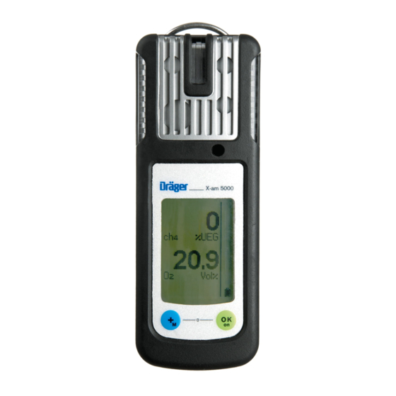
Page 9: What Is What
What is What What is What Front panel Gas entry Alarm LED Buzzer X-am 5000 Display Tool for replacing the sensor Rear panel IR interface Fastening clip Type plate Charging contacts Power pack Serial no. Display for 5 measuring channels…
-
Page 10: Special Symbols
What is What Special symbols Fault message, refer to page 15 Warning message, refer to page 15 The peak value display for all measuring gases, refer to page 15 The exposure evaluation display (TWA) for measuring gases, e.g., H S and refer to page 15 The exposure evaluation display (STEL) for measuring gases, e.g,.
-
Page 11: Configuration
Different settings can be selected to meet customer requirements on delivery. The current setting can be che- cked and changed with the Dräger CC Vision software. A version of Dräger CC-Vision suitable for the Dräger X-am 5000/2000 can be downloaded on the product page of the X-am 5000: www.draeger.com. In the case of O…
-
Page 12: Standard Device Configuration
Different settings can be selected to meet customer requirements on delivery. The current setting can be checked and changed with the Dräger CC Vision software. A version of Dräger CC-Vision suitable for the Dräger X-am 5000/2000 can be downloaded on the product page of the X-am 5000: www.drae- ger.com.
-
Page 13: Operation
Operation Operation Switching on the device • Press and hold the key for approx. 3 seconds until the countdown » 3 . 2 . 1 « shown in the display has elapsed. − All the display segments, including the visual, audible and vibration alarms, are ac- tivated for a short time.
-
Page 14: During Operation
0 to 100%LEL. WARNING When using a CatEx sensor in the Dräger X-am 5000, a calibration of zero point and sensitivity must be carried out after an impact load that results in a fresh air display not equal to zero.
-
Page 15: Calling The Info Mode
Operation Calling the Info Mode • In measuring mode, press the key for approx. 3 seconds. If any warning or fault messages exist, the corresponding information or error codes are displayed (page 24 to page 30). Press the key successively for the next display. The peak values and the exposition values TWA and STEL are displayed.
-
Page 16: Calling The Quick Menu
Operation Calling the Quick Menu − Only the fresh air calibration is activated in the quick menu on delivery. The PC soft- ware Dräger CC Vision can be used to activate the bump test for the quick menu and/or the function for displaying and deleting peak values. •…
-
Page 17: Calling The Calibration Menu
Operation Quick menu «Displaying and deleting peak values» After the function has been selected, the current peak values are displayed; the peak values special symbol appears in %LEL the display at the same time. Vol% • The peak values can be deleted by pressing the key for 5 sec.
-
Page 18: Calibration Menu Functions
Operation − The display shows » 000 «, with the first digit flashing. • Use the key to set the flashing digit. • Press the key, the second digit starts flashing. • Use the key to set the flashing digit. •…
-
Page 19: Identifying Alarms
Identifying Alarms Identifying Alarms An alarm is displayed visually, audibly and through vibration in a specific pattern. Concentration pre-alarm A1 The alarm is indicated by an intermittent alarm message: Display » A1 « and measured value alternating: not for O −…
-
Page 20: Stel / Twa Exposure Alarm
Identifying Alarms STEL / TWA exposure alarm The alarm is indicated by an intermittent alarm message: Display » A2 « and » « (TWA) or » « (STEL) and measured value alternating: CAUTION Leave the area immediately. After this alarm, the deployment of per- sonnel is subject to the relevant national regulations.
-
Page 21: Operation With Pump
Operation with pump Operation with pump With Dräger Pump X-am 1/2/5000 Accessories: Dräger Pump X-am 1/2/5000, sampling hose and probes, refer to Order List, see “Accessories” on page 57.. Commissioning and performing the measurement: • Refer to the Instructions for Use of the Dräger Pump X-am 1/2/5000. With manual pump adapter and rubber ball pump Accessories: For manual pump adapter, rubber ball pump, sampling hose and probes, refer to Order…
-
Page 22: Configuring The Device
The installed PC software Dräger CC Vision is used for configuration. • Observe the documentation and online help of the software. − A version of Dräger CC-Vision suitable for the Dräger X-am 5000 can be downloaded on the product page of the X-am 5000: www.draeger.com.
-
Page 23: Read Database And Display Graphically
Read Database and Display Graphically Read Database and Display Graphically To read the database of the device and display it graphically, the device must be con- nected with a PC. Dräger USB 1.1 GasVision USB DIRA with USB cable (order no. 83 17 409) Dräger USB 1.1 GasVision…
-
Page 24: Faults, Cause And Remedy
Faults, Cause and Remedy Faults, Cause and Remedy Fault Cause Remedy Not possible to switch on Discharge the power pack Charge the power pack, the device page 46. Discharge the alkaline batte- Insert new alkaline batteries, ries page 45. Not possible to switch off The device is not set to Select measuring mode.
-
Page 25
Faults, Cause and Remedy Special symbol » « Cause Remedy and displayed numerical code: Ex concentration has drifted Carry out fresh air calibration, into the negative range page 38. The temperature is too high Operate the device within the allowed temperature range. The temperature is too low Operate the device within the allowed temperature range. -
Page 26
Faults, Cause and Remedy Special symbol » « Cause Remedy and displayed numerical code: The calibration interval for Carry out span calibration for DrägerSensor XXS EC2 has DrägerSensor XXS EC 3, elapsed page 42. Alarm setpoint A2 setting is Set alarm setpoint to less than greater than 60 %LEL 60 %LEL. -
Page 27: Fault Messages
Faults, Cause and Remedy Fault messages Special symbol » « Cause Remedy and displayed numerical code: The customer’s service life Reset the service life counter counter has elapsed using Dräger CC Vision. The device is defective The device must be repaired by DrägerService.
-
Page 28
Faults, Cause and Remedy Special symbol » « Cause Remedy and displayed numerical code: The measurement value of Carry out fresh air calibration, DrägerSensor CatEx 125 PR page 38. is in the negative range DrägerSensor CatEx 125 PR Check DrägerSensor is not inserted or defective CatEx 125 PR, page 49. -
Page 29
Faults, Cause and Remedy Special symbol » « Cause Remedy and displayed numerical code: Device incorrectly configured Change sensor for applicable by Dräger CC-Vision. channel with Dräger CC-Vision. Error during warm-up accele- Disconnect and reconnect ration Dräger Sensor XXS power pack or replace the sen- sor. -
Page 30
Faults, Cause and Remedy Special symbol » « Cause Remedy and displayed numerical code: Error during the function test Repeat function test. Calibrate with gas (bump test) of Drä- or replace DrägerSensor XXS gerSensor XXS EC3 EC3, if necessary page 49. Failed filter test. -
Page 31: Maintenance
Maintenance Maintenance Maintenance intervals The device should be inspected and maintained by suitably qualified persons annually (consult: EN 60079-29-2 – Gas measuring device — Selection, installation, use and maintenance of apparatus for the measurement of combustible gases or oxygen, EN 45544-4 – Electrical apparatus used for the direct detection and direct concentra- tion measurement of toxic gases and vapors — Part 4: Guide for selection, installation, use and maintenance and national regulations).
-
Page 32: Carrying Out The Function Test With Gas (Bump Test)
Maintenance Carrying Out the Function Test with Gas (Bump Test) Manual implementation without the documentation of results in the device memory • Prepare a test gas cylinder, the volu- me flow must be 0.5 L/min and the 0.5 L/min gas concentration must be higher than the alarm setpoint concentration to be tested.
-
Page 33: Menu Implementation With The Documentation Of Results In The Device Memory
Maintenance Menu implementation with the documentation of results in the device memory The «Quick bump test» or the «Extended bump test» is selected using the Dräger CC Vision PC software. The «Quick bump test» checks whether the gas concentration has exceeded the Alarm 1 threshold (with oxygen, the check is whether the concentration has fallen below the Alarm 1 threshold).
-
Page 34
Maintenance − The current gas concentration values and the special symbol » « (for bump test) flash. %LEL • Press the key to start the function test with gas. Vol% • Open the test gas cylinder valve to let test gas flow over the sensor. −… -
Page 35: Automatic Implementation With The Bump Test Station
Maintenance Automatic implementation with the Bump Test Station Prerequisite: The device must first be configured for the automatic function test with gas (bump test) using the PC software Dräger CC Vision. − Activating the device for the automatic function test. −…
-
Page 36
Maintenance • Remove the device from the Bump Test Station. − If the concentration values have now fallen under the A1 alarm setpoints, the device returns to the measuring mode. − An error will be triggered if the preset bump test concentration is not reached within the specified time. -
Page 37: Calibrating The Device
Maintenance Calibrating the Device Calibration may not be possible due to device and channel errors. Allow the sensors to warm up before the calibration! Warm-up time: see Instructions for Use/data sheets of the installed DrägerSensors (at www.draeger.com). Calibration interval: − Observe the relevant specifications in the Instructions for Use/data sheets of the DrägerSensors installed.
-
Page 38: Carrying Out The Fresh Air Calibration
Maintenance Carrying out the fresh air calibration To improve the zero point accuracy, you can carry out a fresh air calibration. NOTICE If none of the sensors fitted permits calibration with fresh air (e.g. only O , only IR- ), fresh air calibration is not offered as a menu function. −…
-
Page 39
Maintenance − The display containing the current gas concentration changes with the display » OK «. %LEL • Press the key to confirm the calib- ration or wait for approx. 5 seconds. Vol% If a fault occurred during the fresh air calibration. -
Page 40: Carrying Out 1-Button Calibration
Maintenance Carrying out 1-button calibration NOTICE If no sensors are enabled for 1-button calibration by the Dräger CC Vision PC pro- gram, the 1-button calibration menu function will not be offered. − All sensors that are enabled by the Dräger CC Vision PC program take part in the 1- button calibration.
-
Page 41
Maintenance • Open the test gas cylinder valve to let test gas flow over the sensor. − The currently displayed measured values start to flash. The flashing stops after a static measured value has been reached. − The calibration is now carried out automatically. −… -
Page 42: Calibrating The Sensitivity For An Individual Measuring Channel
• Connect the test gas cylinder with the calibration cradle. • Vent the test gas into a fume cup- X-am 5000 board or into the open air (with a hose %LEL Vol% connected to the second connector of the calibration cradle).
-
Page 43: Span Calibration For Catex
Maintenance Span calibration for CatEx − If the measuring range end value < = 100%LEL, the adjustment for the heat tinting is offered. − Display in the case of channel selection: • Open the test gas cylinder valve to let test gas flow over the sensor.
-
Page 44
Maintenance If a fault occurred during the span calibration. − The fault message » « appears %LEL and » « is displayed for the sensor instead of the measured value. • In this case, repeat the calibration. Vol% If necessary, replace the sensor, page 49. -
Page 45: Replacing The Batteries / Rechargeable Batteries
Maintenance Note on adjusting the Ex channel to nonane as the measured gas: − When calibrating the Ex channel, propane can be used as a substitute for the calibration gas. − When using propane to adjust the Ex channel to nonane, the display must be set to 2x the test gas concentration used.
-
Page 46: Charging The Rechargeable Batteries
Maintenance After replacing the power pack T4, it is recommended that a complete charging is car- ried out. After the batteries have been replaced: − The settings and data are stored when the battery is replaced. The sensors warm up again. Charging the rechargeable batteries WARNING Do not charge underground or in explosion-hazard areas! Danger of explosion!
-
Page 47
Maintenance X-am 5000 X-am 5000 X-am 5000 %LEL %LEL %LEL Vol% Vol% Vol% • Attach additional charging modules in the same way. − Always connect or disconnect the charging modules individually and not in groups in order to prevent the charging station from becoming damaged. During transpor- tation, the power pack and the charging modules should also always be handled in- dividually and without inserted devices. -
Page 48: Adapter
83 18 785) is suitable for charging a device. − When using the vehicle charging adapter (order no. 45 30 057) it is recommended that you supply every charging module separately. X-am 5000 %LEL Vol% 83 16 994 (100 … 240 V) 83 17 754 83 15 635 (100 …
-
Page 49: Replacing The Sensors
Replacing the Sensors Replacing the Sensors • To replace the sensors of the device, connect the device with a PC. • Replace the sensors using the PC program Dräger CC Vision. Dräger USB 1.1 CC-Vision USB DIRA with USB cable (order no.
-
Page 50
Replacing the Sensors Electrochemical sensors WARNING Do not throw into fire, Do not force open. Danger! Acid burn risk! Sensors of type XXS O and XXS NO LC contain small quantities of nanomaterials. Like batteries, only dispose of as special waste, in accordance with local waste disposal regulations. -
Page 51: Sensor Warm-Up Acceleration
The time to activate the calibration is not changed. • In order to use the sensor warm-up acceleration function in the Dräger X-am 5000, at least one sensor suitable for the purpose must be fitted and registered in the unit using the Dräger CC-Vision PC software.
-
Page 52: Care
Care − Start of the warm-up acceleration. − The remaining time is displayed and decremented. WARNING This function requires that the device is in a gas-free environment. A warning screen is displayed and the remaining time during which no gas may be applied is shown It is essential to 04:08 ensure that the sensor is in the fresh air…
-
Page 53: Disposing Of The Device
Disposing of the Device Disposing of the Device Dispose of product in accordance to applicable regulations. WEEE In accordance with EU Directive 2002/96/EC thisproduct must not be disposed of as household waste. It is therefore marked with the icon opposite. You can return this product to Dräger free of charge.
-
Page 54: Technical Data
Technical Data Technical Data X-am 5000 Ambient conditions: during operation and –20 to +50 °C for NiMH power packs type: storage HBT 0000 and HBT 0100, with alkali single cells type: Duracell Procell MN 1500 -20 to +40 °C for NiMH single cells type:…
-
Page 56: Order List
Order List Order List Name and Description Order No. Dräger X-am 5000 83 20 000 Unlimited 1 to 5 multi gas monitor with exchangeable sensors. With selectable special calibration. Standard calibration of the Ex sensor: Methane. Inclusive to country-specific adjustable standard alarm set- points.
-
Page 57: Accessories
Order List Name and Description Order No. Accessories The accessories are not subject to BVS10 ATEX E 080X and PFG 10 G 001X. Pump accessories: Dräger Pump X-am 1/2/5000 83 19 400 Case for Dräger Pump X-am 1/2/5000 83 19 385 Rubber ball pump 68 01 933 Manual pump adapter…
-
Page 58: Spare Parts
, CO and H S >5 years, CatEx > 3 years. Data sheets for all sensors that can be used for the device can be downloaded on the product page of the X-am 5000 at the following Internet address: www.draeger.com.
-
Page 59: Declaration Of Conformity
Declaration of Conformity Declaration of Conformity…
-
Page 60
Dräger Safety AG & Co. KGaA Revalstraße 1 D-23560 Lübeck Germany Phone +49 451 8 82- 0 +49 451 8 82- 20 80 www.draeger.com 90 23 999 — TM 4638.210 en © Dräger Safety AG & Co. KGaA Edition 11 — February 2013 (Edition 01 — April 2007) Subject to alteration Visit: www.thesafetyequipmentstore.com or besafe@thesafetyequipmentstore.com for sales and service.
Specifications:2044/2044183-xam_5000.pdf file (30 Nov 2022) |
Accompanying Data:
Dräger X-AM 5000 Gas Detectors, Measuring Instruments PDF User Manual Manual (Updated: Wednesday 30th of November 2022 09:20:37 AM)
Rating: 4.5 (rated by 38 users)
Compatible devices: RVP 5000, Panorama Nova PE/ESA, PIR 7200, 68 01 933, REGARD 39 0 Series, Flame 5000, X-am 3500, Polytron 8700.
Recommended Documentation:
Text of User Manual Manual
(Ocr-Read Version Summary of Contents, UPD: 30 November 2022)
-
3, 3 Zu Ihrer Sicherheit Vor Gebrauch des Produkts diese Gebrauchsanweisung und die der zugehö- rigen Produkte aufmerksam lesen. Gebrauchsanweisung genau beachten. Der Anwender muss die Anweisun- gen vollständig verstehen und den Anweisungen genau Folge leisten. Das Produkt darf nur entsprechend dem Verwendungszweck verwendet werden. Gebrauchsanweisung nicht entsorgen. Auf…
-
56, Dräger X-AM 5000 56 Efectuar o teste de absorção de gás (Bump Test) Preparar a garrafa com gás de teste, de modo que o fluxo volumétrico seja de 0,5 L/min e a concentração de gás superior à concentração do valor limite a testar. Ligar a garrafa com gás de teste à base de calibração (Nº enc. 83 18 752). Ligar o aparelho e colocar na base de calibraç�…
-
66, 66 Attivazione del menu rapido In modalità di rilevamento premere tre volte il pulsante [+]. – Se con il software «Dräger CC-Vision» sono state attivate le funzioni relative al menu rapido, allora si potranno selezionare tali funzioni con il pulsante [+]. Se nel menù rapido non risulta attivata alcuna funzione l’apparecchio resta in modalità di ri…
-
212, 212 Se cuplează aparatul şi se introduce în furca de calibrare. Se apasă tasta [+] şi se menţine 5 secunde pentru a accesa meniul de calibrare, se introduce parola (parola la livrare = 001). Selectaţi cu tasta [+] funcţia Ajustare cu un gaz, se aprinde intermitent simbolul pentru ajustarea sensibilităţii »«. Apăsaţi tasta [OK] pentru a porni selectare…
-
196, 196 Проверка на параметрите За да се гарантира, че стойностите са били пренесени коректно върху уреда за измерване на газове: Команден бутон Изберете данните от X-am 1/2/5×00 в CC-Vision. Проверете параметри…
-
69, 69 modalità di rilevamento. Chiudere la valvola della bomboletta del gas di prova ed estrarre l’apparecchio dalla gabbia di calibrazione. Se durante la regolazione della sensibilità si è verificato un errore: – Appare l’indicazione di riscontro di un’anomalia »« e al posto del valore misurato appare »« in relazione al sensore interessato. I…
-
157, 157 s dovedenim ispitnim plinom. Ako je prikazana mjerna vrijednost stabilna (nakon minimalno 120 sekundi): Pritisnite tipku [OK] kako biste proveli ugađanje. – Pokazatelj aktualne koncentracije plina izmjenjuje se s pokazateljem «OK». Pritisnite tipku [OK] ili pričekajte oko 5 sekundi kako biste završili ugađanje ovoga mjernog kanala. – Zatim se …
-
232, 232 Λειτουργία Info-Off Έχοντας απενεργοποιήσει τη συσκευή πιέστε το πλήκτρο [+]. Για όλα τα κανάλια εμφανίζονται όνομα αερίου, μονάδα μέτρησης και τελική τιμή πεδίου μέτρησης. Πατώντας ξανά το πλήκτρο [+] τ…
-
86, Dräger X-AM 5000 86 Kontrol af parameter For at sikre, at værdierne overføres korrekt til gasmåleren: Vælg knappen Data fra X-am 1/2/5×00 i CC-Vision. Kontrollér parameter. Første ibrugtagning Før første ibrugtagning af instrumentet skal de medfølgende batterier eller en opladet NiMH-strømforsyningsenhed T4 (type HBT 0000, bestillingsnr. 83 18 704) / T4 HC (type HBT 0100, …
-
108, 108 Kontroll av parametrene For å kontrollere at verdiene er overført riktig til gassmåleinstrumentet: Velg knappen Data fra X-am 1/2/5×00 i CC-Vision. Kontroller parametre. Første gangs bruk Før første gangs bruk av instrumentet skal de vedlagte batteriene eller en oppladet NiMH-forsyningsenhet T4 (type HBT 0000, bestillingsnr. 83 18 704) / T4 HC (t…
Dräger X-AM 5000 Recommended Instructions:
FIGHTER 1250, DW756, 40A, J2BP85


-
STATUS SCIENTIFIC CONTROLS
FGD2
STATUS SCIENTIFIC CONTROLS Issue: 8 Date: 14/10/19 Version: 9.6P FGD2 & 3 Atex Flammable Gas Detector Heads STATUS SCIENTIFIC CONTROLS LTD. Hermitage Lane Industrial Estate, Kings Mill Way, Mansfield, Nottinghamshire. NG18 5ER England Tel Fax : 01623 651381 : 01623 421063 …
FGD2 26
-
LEGRAND
Tynetec Aidcall ZXT486
Doc No. FM0725 issue C Page 1 169MHz Telecare Devices Gas Detector __________________________________________________________________________________________________________ • Compatible with Reach at-home alarms, Advent xt warden call, Altec Response and Touchsafe Pro Nursecall systems • Alarm at 10% of LEL (Lower Explosive Limit) • 85dB @ 1m sounder � …
Tynetec Aidcall ZXT486 6
-
Tecno Control
SE155M
IST-2155.SM02.01 Istruzione / User’s Manual / Manuel d’utilisation Pag. .1/2 (IST-2155 SM02.01.DOC) Cercafughe portatile di gas Portable gas leaks detector Détecteur portatif de gaz TECNOCONTROL S.r.l. — Via Miglioli, 47 20090 SEGRATE (MI) Tel. 02/26922890 — Fax 02/2133734 http: www.tecnocontrol.it e-mail: [email protected] SE155M IT DESC …
SE155M 2
-
GasTech
D-Guard
D‐GuardTMDigitalGuardIntrinsicallySafeIntelligentGasDetectorPartNumber65‐1010xxxManualRevisionv2.08(updated5June2009) …
D-Guard 47
-
WatchGas
BAT-1
1 ● WatchGas B.V. ● Klaverbaan 121, 2908KD, Capelle a/d IJssel, The Netherlands ● ● T: +31 (0) 85 0187709 ● [email protected] ● www.watchgas.eu WatchGas BAT-1, 2, 3 Breathing Air Quality Test Kit Full Compliance with BS EN12021 Edition 11, August 2021 …
BAT-1 19
-
Sensor Electronics
SEC 3000
SEC 3000 Gas Detector Instruction and Operation Manual Sensor Electronics Corporation 5500 Lincoln Drive Minneapolis, Minnesota 55436 USA (952) 938-9486 Fax (952) 938-9617 Email [email protected] Part Number 75-3000 Version 091404-001 …
SEC 3000 14
-
SeeedStudio
Grove MQ3
1 Grove — Gas Sensor (MQ3) Version: 1.0 Release date: 9/20/2015 Wiki: http://www.seeedstudio.com/wiki/Grove_-_Gas_Sensor(MQ3) Bazaar: http://www.seeedstudio.com/depot/Grove-Gas-SensorMQ3-p-1418.html …
Grove MQ3 16
-
Riken Keiki
SC-8000
PT0E-1050 Portable Toxic Gas Monitor SC-8000 Operating Manual (PT0-105) Request for the Customers • Read and understand this operating manual before using the gas monitor. • Use the gas monitor in accordance with the operating manual. • Regardless of warranty period, we shall not make any indemnification for accidents and damage caused by using this product. The indem …
SC-8000 49