

Ваша корзина пуста
Выберите в каталоге интересующий товар
и нажмите кнопку «В корзину».
Перейти в каталог

Отложенных товаров нет
Выберите в каталоге интересующий товар
и нажмите кнопку ![]()
Перейти в каталог

Зарядное устройство программируемое 48V 25A EAGLE
Зарядное устройство программируемое 48V 25A EAGLE
Описание
В нашем интернет-магазине вы можете приобрести качественные запчасти по доступным ценам. Мы предлагаем продукцию известных производителей из России и других стран.
Мы работаем только с проверенными поставщиками, хорошо зарекомендовавшими себя по результатам долгосрочного сотрудничества с нашей компанией.
Качественные комплектующие и запчасти являются залогом того, что Ваш электромобиль прослужит Вам максимально долго и будет безопасен в эксплуатации.
Отзывы
Отзывов ещё нет – ваш может стать первым
Error 16 — VE.Bus dongle is missing
(Ошибка
16- потеря ключа шины VE.Bus)
Обновление
прошивки до последней версии — ключи шины VE.bus больше не нужны.
Инструкции
по обновлению ПО находятся здесь (https://victronenergy.store/obnovlenie-proshivki-invertorov-victron-energy—ve-bus-s-ispolzovaniem-veflash)
Error 17 — Phase master missing
(Ошибка
17 — потеря задающего фазу устройства (Master missing))
Ошибка
17 показывается только на ведомых устройствах (Slave). Ведомые устройства в
системе сообщат об этой ошибке, когда связь с задающим устройством (Master)
будет потеряна.
Эта
ошибка может возникнуть только в системах с несколькими устройствами,
установленными на одной фазе. Например, однофазная установка с двумя или более
устройствами параллельно или трехфазная установка с шестью или более
устройствами.
Ниже
указаны возможные причины и шаги, которые необходимо предпринять для поиска
проблемы:
1. В
некоторых случаях эта ошибка может быть отмечена временно, при использовании
удаленного VEConfigure — при записи новой конфигурации системы.
Решение:
не обращайте внимания на ошибку — система восстановится сама по себе.
2. Наиболее
вероятной причиной является проблема связи, связанная с качеством кабеля VE.Bus.
Решение:
сначала проверьте разъемы сетевых кабелей. Если это не решит проблему, замените
все сетевые кабели, включая кабель к устройству GX. Убедитесь также в том, что
вы проверяете разъемы розетки RJ-45, а не только кабели: иногда плохо
установленные кабельные разъемы RJ45 мешают пружинным контактам в разъемах
розетки RJ45 на Multi плотно подсоединять контакты. Убедитесь, что кабели
сделаны фабричным способом. Не используйте самодельные кабели.
3. Перегорел
предохранитель постоянного тока. В этом случае кажется, что все работает
нормально — пока есть сеть 220В. Но затем, когда на входе больше нет напряжения
переменного тока (сеть выходит из строя или генератор останавливается), блоки без питания DC — автоматически отключаются
от системы.
Решение:
проверьте предохранитель на всех блоках, замените перегоревший.
4. Обновите
прошивки и программы Assistants для инвертора.
А так же для всех устройств GX.
Решение: обновить прошивки здесь:
Update the Inverter/charger firmware (https://victronenergy.store/obnovlenie-proshivki-invertorov-victron-energy—ve-bus-s-ispolzovaniem-veflash)
Updatethe GX Device firmware (https://victronenergy.store/color-control-gx-obnovlenie-do-versii-2-xx)
Системы с несколькими ведомыми
устройствами (Slave) на одной фазе.
Ошибка
Error 17 может отображаться на одном или нескольких ведомых устройствах (Slave),
подключенных по одной фазе (информация видна при взгляде на светодиоды на
передней панели инвертора, а не на портале VRM или мониторе GX). Если ведомые
устройства (Slave) все еще могут общаться друг с другом, то ошибка будет
отображаться только на одном ведомом устройстве (Slave). Это надо иметь ввиду, что
все ведомые устройства , которые могут видеть друг друга в сети, и если один ведомый
уже показывает ошибку Error 17, то другие не будут
показывать эту ошибку.
Не удалось решить эту
проблему?
Если
после всех вышеперечисленных шагов вы все еще видите ошибку Error 17,
обратитесь к своему дилеру, который свяжется с Victron службой поддержки.
Пожалуйста,
предоставьте фотографии прибора, места установки и сетевого кабеля. В
зависимости от ситуации они могут посоветовать заменить устройство GX или
инвертор. Мы советуем сначала заменить кабели, а если это не поможет, то
сначала только устройство GX, так как для
этого потребуется меньше усилий, чем для
замены Multi.
Error 18 — AC Over-voltage
on the output of a slave while switched off
(Ошибка
Error 18 — присутствие напряжения переменного тока на выходе ведомого
устройства (Slave) при выключенном питании).
Решение
проблемы: проверьте, не были ли перепутаны провода переменного тока. Когда
устройство выключено, напряжение на выходе переменного тока AC Out — всегда
отсутствует.
Error 22 — This device
cannot function as a slave
(Ошибка
22 — Это устройство не может функционировать в качестве ведомого устройства
(Slave))
Причина:
Это устройство является устаревшей и непригодной для
этих целей моделью. Оно должно быть заменено.
Error 24 — Switch-over system
protection initiated
(Ошибка
24 — инициирована Защита системы переключения).
Эта
ошибка означает, что один или несколько блоков сообщают о передаче обратного
тока через свое Back-Feed реле, в то время как эти
реле должны быть разомкнуты. И, соответственно, никакой ток не может протекать
через разомкнутую цепь.
Что
такое реле обратной подачи? Это реле, которое замыкается при подключении к сети
220В или генератору. И которое размыкается, когда нет доступного входного питания,
то есть когда система находится в режиме Island или в режиме Инвертирования.
Ошибка
Error 24 возникает, когда Multi или Quattro обнаруживает
ток, протекающий через Back-Feed реле в течение одного периода,
когда реле должно быть разомкнуто. Это может означать одно из двух:
1. Реле
не переключилось.
2. Соответствующая
схема датчика переменного тока — неисправна.
Ошибка
Error 24 — это очень редкая ошибка. Возможные причины (в порядке вероятности
возникновения):
1. Слишком
большая нагрузка переменного тока (чаще — индуктивная) подключена в тот момент,
когда реле должно отключиться. Этот большой ток будет препятствовать размыканию
контактов реле.
Решение:
снимите чрезмерную нагрузку. Для получения максимальной номинальной мощности
смотрите раздел мощность реле в таблице данных на конкретный инвертор.
2. Входное
напряжение переменного тока медленно снижается до нижнего предела. Обычно это
происходит в системах с генератором. Это особенно характерно с такими нагрузками
переменного тока, которые увеличивают свою потребляемую мощность при падении питающего
напряжения переменного тока — к тому
моменту времени, когда инвертор/зарядное устройство инициирует отключение (при
просадке напряжения), ток через реле значительно превышает номинальные значения
и слишком высок, чтобы разомкнуть контакты реле.
Решение:
сделайте отключение Multi или Quattro более ранним — поднимите нижний предел
входного напряжения переменного тока в настройках VEConfigure3. Например, до 200В
или 210 В переменного тока. По умолчанию — заводская настройка составляет 180 В
переменного тока.
3. Back-Feed реле имеет
аппаратный сбой.
Решение:
замените неисправный блок реле.
4. Соответствующая
схема измерения переменного тока неисправна.
Решение:
замените неисправный блок.
Как диагностировать
параллельную, мульти- или двухфазную систему?
Ошибка
24 всегда будет появляться на всех блоках одновременно. К сожалению, нет
никакой индикации, ни на светодиодах, ни на устройстве GX, VRM или любым другим способом,
чтобы увидеть, какое из устройств вызвало ошибку. Ниже приведены процедуры,
описывающие, как вручную определить, какой блок имеет неисправное реле.
Для
начала, дважды проверьте Вариант 1 и 2 в
приведенном выше списке процедур. Это самые распространенные причины. В случае,
если это не приведет к решению проблемы, выполните нижеуказанные процедуры,
чтобы выяснить, является ли это проблемой реле, а затем — какой блок вышел из
строя.
Выполните
эту процедуру сразу после возникновения ошибки — не пытайтесь сначала
перегрузить (сбросить) систему.
1. Начните
с создания видео (фотофиксация) всех блоков и их светодиодного кода. В начале
проверки не сбрасывайте систему, а также не сбрасывайте ее после создания
видео.
2.
Полностью отключите все провода переменного тока, как входную, так и выходную
группы, на всех блоках. Сделайте фотографии терминалов — для того, чтобы не
было никакого недопонимания при
обсуждении с техническим консультантом.
3.
Теперь с помощью омметра измерьте сопротивление между нейтральными клеммами на
входе переменного тока и выходе переменного тока — рабочий блок не будет
показывать никакой связи между этими клеммами (разрыв). А также измерьте
сопротивление между клеммами переменного тока — Line AC Input и переменного тока — Line AC Output (вход и выход).
Неисправный
блок будет показывать нулевое или близкое к нулю сопротивление.
Исправный
блок показывает разрыв (бесконечное сопротивление) между входом и выходом (Line
In и
Line Out).
Между
клеммами Neutral In и Neutral Out — должно быть сопротивление несколько сотен Ом.

-
Contents
-
Table of Contents
-
Bookmarks
Quick Links
HAMMERHEAD
CHARGER 48V
Electric Vehicle Operator’s Manual
Related Manuals for Hammerhead Charger 48V
Summary of Contents for Hammerhead Charger 48V
-
Page 1
HAMMERHEAD CHARGER 48V Electric Vehicle Operator’s Manual… -
Page 2: Table Of Contents
HAZARD LIGHT SWITCH …………………… 1 2 SPEEDOMETER …………………….. 1 2 ACCELERATOR PEDAL …………………… 1 3 BRAKE PEDAL …………………….. 1 3 PARKING BRAKE LEVER …………………… 1 3 BED USE ………………………… 1 4 MANUAL LIFT BED OPERATION …………………. 1 5 TAIL GATE OPERATION …………………… 1 6 OPERATING THE VEHICLE …………………… 1 7 Hammerhead Charger Electric Vehicle Operator’s Manual Page 1 …
-
Page 3
Brakes ……………………….. 2 4 Rear Axle ………………………. 2 4 Fasteners ………………………. 2 4 BATTERIES AND CHARGING …………………… 2 5 Batteries ………………………. 2 5 Charger ………………………. 2 5 GENERAL SPECIFICATIONS …………………… 2 6 LIMITED WARRANTY POLICY ……………………. 2 8 Hammerhead Charger Electric Vehicle Operator’s Manual Page 2 … -
Page 4: Safety Information
No warning can take place of good common sense and prudent driving practices. With electric powered vehicles, be sure that all electrical accessories are grounded directly to the (‐) post. Never uses chassis or body as a ground connection. Never modify the vehicle in any way that will alter the weight distribution of the vehicle, decrease its stability or increase the speed beyond the factory specification. Such modifications can cause serious personal Injuries or death. Do not make any such modifications or changes. The manufacturer prohibits and disclaims responsibility for any such modifications or any other alternation which would adversely affect and safety of the vehicle. Once again thank you for purchasing Hammerhead product, and we hope you will have an enjoyable experience. Hammerhead Charger Electric Vehicle Operator’s Manual Page 3 …
-
Page 5: General Operation Instructions
Never charge a battery in an area that is subject to flame or spark. Pay ‐ particular attention to natural gas or propane gas water heaters and furnaces. Battery charger must be operated according to manufacturer’s instructions. ‐ Please refer to battery charger’s separate operator’s manual for further instructions. Hammerhead Charger Electric Vehicle Operator’s Manual Page 4 …
-
Page 6: Display Of Warning Labels
DISPLAY WARNING LABELS Following are the warning labels affixed to the vehicles; read, observe and follow all warning and operation instructions carefully. Failure to follow these warnings can result in series injuries or death. Hammerhead Charger Electric Vehicle Operator’s Manual Page 5 …
-
Page 7
DISPLAY OF WARNING LABELS ‐ 2 Hammerhead Charger Electric Vehicle Operator’s Manual Page 6 … -
Page 8: Display Of Controls
DISPLAY OF CONTROLS 1. Steering Wheel 2. Combination Lever 3. Digital Speedometer 4. Key Switch / Light Switch 5. Directional Selector 6. State of Charging Meter 7. Hazard Switch 8. Radio (optional) 9. Glove Compartment 10. Brake Pedal 11. Accelerator Pedal 12. Front Batteries access panel Hammerhead Charger Electric Vehicle Operator’s Manual Page 7 …
-
Page 9: Before Initial Use
Five air exchanges per hour is considered the minimum requirements. Never charge a battery in an area that is subject to flame or spark. Pay particular attention to natural gas or propane gas water heaters and furnaces. Before a new vehicle is put into operation, the “Initial Service Check List” below must be performed to ensure safety operation of the vehicle. Determine and record braking distance required to stop vehicle for future brake performance tests. Initial Service Check List Fully charge batteries Check brake operation and adjust if necessary Check brake hydraulic brake fluid level Check parking brake and adjust if necessary Check accelerator pedal and brake pedal make sure they are not sticking Check tire pressure (see SPECIFICATION) Check head lights, turn signals, brake lights Hammerhead Charger Electric Vehicle Operator’s Manual Page 8 …
-
Page 10: Batteries
There are another four batteries located underneath the bench seat. (See location image below) ON‐BOARD CHARGER The 110‐Volts Delta‐Q onboard charger is located under the seat on the driver’s side of the vehicle (see image below). It is wired directly to the batteries. There is also a charging port below the driver’s seat that can be plugged directly into any 110 Volt wall outlets. (See location image below). For more information about Delta‐Q Charger, please reference included copy of Delta‐Q charger’s operators manual. Hammerhead Charger Electric Vehicle Operator’s Manual Page 9 …
-
Page 11: Controls And Indicators
To prevent inadvertent operation of the vehicle when left unattended, the key should be turned to the ‘OFF’ position and removed. The key switch also has a position for turn on the head lights. (See image below) Hammerhead Charger Electric Vehicle Operator’s Manual Page 10 …
-
Page 12: Direction Selector
) URNING IGNALS IGH EAM IGHTS Much like a car’s turning signal lever, this combination lever is located below the steering wheel on the steering column operates turning signals, high/low beam lights and horn. Push down on the combination lever to signal turning left, push up the lever to signal turning right. Push in on the lever to turn on high beam, pull back on the lever to turn on the high beam. Push in on the end of the lever to horn. (See image below) Hammerhead Charger Electric Vehicle Operator’s Manual Page 11 …
-
Page 13: Hazard Light Switch
Digital speedometer is located in the middle of the console. It displays current speed information in MPH, as well as odometer in Miles. At the bottom of the speedometer are turning signal indicators, parking brake indicator and high beam indicator. (See image below) Hammerhead Charger Electric Vehicle Operator’s Manual Page 12 …
-
Page 14: Accelerator Pedal
With the key switch “ON”, release the parking brake, depressing the accelerator starts the motor. When pedal is released, the motor will stop. To stop the vehicle more quickly, depress the brake pedal. (See image below) BRAKE PEDAL This vehicle is equipped with hydraulic brake system that controls a set of four brake discs; one on each wheel. To slow down the vehicle or to stop the vehicle, depress the brake pedal. Depressing the brake pedal further will increase the effectiveness of braking. (See Image Below) PARKING BRAKE LEVER This vehicle is equipped with parking brake lever. Push the release button and then pull the parking brake lever up to active parking brake. When parking the vehicle, pull up the parking brake and then turn the key to “OFF” position. (See image below) To release the parking brake, push the release button in and then push the parking brake lever down. Hammerhead Charger Electric Vehicle Operator’s Manual Page 13 …
-
Page 15: Bed Use
Never fill a gas can in bed of a vehicle. Static discharge could ignite gasoline vapor and cause an explosion. Always place a gas can on the ground before filling. NEVER fill a gas can in the bed of the vehicle. Static electricity is build up during the fueling process and could discharge causing the gasoline vapor to ignite. Hammerhead Charger Electric Vehicle Operator’s Manual Page 14 …
-
Page 16: Manual Lift Bed Operation
Raise the bed using handle on the side of the bed. The gas struts will assist in raising the empty load bed and will keep the bed raised. To lower the manual lift bed, grasp the bed handle and lower the bed to the rest position. Be sure fingers are not trapped by the bed. Hammerhead Charger Electric Vehicle Operator’s Manual Page 15 …
-
Page 17: Tail Gate Operation
TAIL GATE OPERATION There are two tailgate switches located on the top side of the bed. To open the tailgate, push the small tab forward on the switch, and pull back the locking plate. (See image below) To close the tailgate, hook the tailgate latch and push down on the locking plate. Hammerhead Charger Electric Vehicle Operator’s Manual Page 16 …
-
Page 18: Operating The Vehicle
Never drive vehicle up, down or across an incline that exceeds 14 degrees. STARTING DRIVING To avoid the possible of roll back which could result in severe injury or vehicle damage, do not release the brake until motor has started. Remove charger plug from vehicle receptacle and properly store the cables before moving the vehicle. To operate vehicle: Hammerhead Charger Electric Vehicle Operator’s Manual Page 17 …
-
Page 19: Staring Vehicle On Ahill
Note: When the direction selector is in the reserve position, a warning signal will sound to indicate that the vehicle is ready to run in reverse. STARING VEHICLE HILL To reduce the possibility of roll‐back which could result in severe injury or vehicle damage, do not release the parking brake lever until motor has started. Do not hold the vehicle on a hill by using accelerator and motor. Leaving motor in a stalled condition for more than 3‐4 seconds will cause permanent damage to the motor. To reduce the possibility of permanent damage to the drive system, it is important to prevent excessive roll‐back when starting the vehicle on a hill. Place left foot on foot brake and release the parking brake. Depress the accelerator with right foot and release the foot brake by lifting the left foot. Hammerhead Charger Electric Vehicle Operator’s Manual Page 18 …
-
Page 20: Vehicle Clearning And Care
VEHICLE CLEARNING CARE When cleaning the exterior of the vehicle, do not use pressure in excess of 700 psi. To reduce the possibility of cosmetic damage, do not use any abrasive or reactive solvents to clean plastic parts. Normal cleaning of vinyl seats and plastic or rubber trim requires the use of a mild soap solution applied with a sponge or soft brush and wipe with damp cloth. Rinse with clear water. Hammerhead Charger Electric Vehicle Operator’s Manual Page 19 …
-
Page 21: Repair
The vehicle is fitted with low pressure tubeless tires mounted on one piece rims; therefore, the most cost effective way to repair a puncture in the thread is to use a commercial tire plug. FUSE REPLACEMENT To replace fuses, locate the fuse block under the bench seat. Pull out old fuse and replace with new fuse. Fuses are available from local authorized repair center. Hammerhead Charger Electric Vehicle Operator’s Manual Page 20 …
-
Page 22
(See images below). There are three types of fuses used on this vehicle, see wiring diagram for details. Do not attempt any type of repairs beyond your technical skills; contact your local authorized repair center for help. Unauthorized repairs can cause serious safety hazard to the operator, as well as permanent damage to the vehicle. Hammerhead Charger Electric Vehicle Operator’s Manual Page 21 … -
Page 23: Service And Maintenance
EHICLE DENTIFICATION LATE OCATION The vehicle Identification plate is on the vehicle behind the driver’s seat. (See image below). Design changes take place on an ongoing basis. In order to obtain the correct components for the vehicle, the VIN number must be provided when ordering service parts. Hammerhead Charger Electric Vehicle Operator’s Manual Page 22 …
-
Page 24: Periodic Maintenance Schedule
To perform service that is in this schedule but not described in this manual, contact a local authorized service center for this vehicle. Daily Service Before Use: Check brake operation Check parking brake operation Check warning device function in reverse Check Lights, turning Signals, Horns Check tire condition Check overall vehicle condition Recharge battery to full state of charge after each day’s use Weekly Service Tires: Exam for cuts, excessive war and pressure Wheels: Check for bent rims, missing or loose lug nuts Monthly Service or Every 20 Hours (includes list in weekly service above) Front Axle: Check for damage to axle and loose or missing hardware Shock Absorbers: Check front and rear shock absorbers for oil leakage and loose fasteners Front Wheel Alignment: Check for unusual tire wear, align if required Parking Brake: Check for bent/binding linkage rod. Hardware and fasteners: Check for loose or missing hardware and components. Semi‐Annual or Every 125 Hours (includes list in previous service above) Direction Selector: Check for wear and smooth movements Steering Assembly: Check for rack and pinion seal or damage or grease leakage Rod End ball Joints: Check for excessive play, Lubricate. Rear Axle: check for unusual noise and loose or missing mounting hardware Annual or Every 250 Hours (includes list in previous service above) Front wheel bearings: Check and adjust as required. Rear Axle: Check lubricant, add lubricant (SAE 30 oil) as required Brake: Clean and adjust. Check for brake pads linings. Check brake fluid. Hammerhead Charger Electric Vehicle Operator’s Manual Page 23 …
-
Page 25: Tire Inspection
To reduce the possibility of severe injury or death, always evaluate pedal travel before operating a vehicle to verify some braking function is present. Check master cylinder fluid annually or if there is a decrease in braking effectiveness. Inspect components for damage or wear. EAR The rear axle is provided with a lubricant level check/fill plug located on the bottom of the differential. Unless leakage is evident, the lubricant need only be replaced after five years. ASTENERS Periodically, the vehicle should be inspected for loose fasteners. Hammerhead Charger Electric Vehicle Operator’s Manual Page 24 …
-
Page 26: Batteries And Charging
If the electrolyte level is barely covering the plates, add distilled or de‐ionized water to a level 1/8” (3mm) below the vent well (this is the plastic shield inside the vent hole) for standard batteries and to the maximum (MAX) level indicator for PLUS Series batteries. After adding water, secure vent cap back on batteries. This vehicle uses Deep Cycle Deep Acid battery from Trojan. Please read “Trojan Battery Users Guide” for more information. HARGER The Delta‐Q charger is programmed to run Trojan batteries. If batteries need to be changed, please contact your authorized dealer for compatibility questions. This vehicle uses a 48 Volt Delta‐Q Charger. Please read included “Delta‐Q Charger Owner’s Manual” for more information. Hammerhead Charger Electric Vehicle Operator’s Manual Page 25 …
-
Page 27: General Specifications
Six 8 Volts Deep Cycle Battery Charger 220 Volt Delta‐Q On Board Charger Top Speed 25 MPH Front Tire Tubeless 21 x 8 ‐10 Front Tire Pressure Maximum 36 PSI Rear Tire Tubeless 23 x 8.5 ‐ 12 Rear Tire Pressure Maximum 36 PSI Weight 990 lbs (450 KG) Length 85” (2330 mm) Width 49” (1300 mm) Height 71” (1750 mm) Wheelbase 63” (1600 mm) Ground Clearance 8.6” (220 mm) Cargo Bed Capacity 39” x 23” x 11” (970 x 590 x 280 mm) Vehicle Payload 1200 Lbs (550 KG) *Specification subject to change without notice Hammerhead Charger Electric Vehicle Operator’s Manual Page 26 …
-
Page 28
Hammerhead Charger Electric Vehicle Operator’s Manual Page 27 … -
Page 29: Limited Warranty Policy
This warranty does not cover damage or faults caused by misuse, negligence, alternation, accidents or any abnormal use including the use of none genuine replace parts, renting or leasing, competition or racing. This warranty does not cover loss of use of the vehicle or loss of time, inconvenience. This warranty also does not cover normal wear and deterioration of consumable items such as tires, brakes, suspension parts, light bulbs, tires, batteries and etc. Hammerhead Charger Electric Vehicle Operator’s Manual Page 28 …
-
Page 30
TROJAN BATTERY USER’S GUIDE Congratulations on your purchase from Trojan Battery Company, the manufacturer of the world’s most trusted deep cycle batteries. The battery you purchased was engineered by Trojan to deliver superior power, performance, durability and reliability for use in a broad range of demanding applications. -
Page 32
TROJAN BATTERY USER’S GUIDE Table of Contents Equipment Needed …………4 Battery Installation . -
Page 34: Equipment Needed
TROJAN BATTERY USER’S GUIDE This User’s Guide was created by Trojan’s applications engineers and contains vital information regarding proper care and maintenance of your new battery. Please read through this user’s guide carefully and completely before using your battery. It will help you achieve optimum performance and long life from your new investment.
-
Page 35: Battery Connections
TROJAN BATTERY USER’S GUIDE Battery Connections 2.2. Battery cables provide the link between the batteries, equipment and charging system. Faulty connections can lead to poor performance and terminal damage, meltdown or fire. To ensure proper connections, please use the following guidelines for cable size, torque values and terminal protection.
-
Page 36: Torque Values
Torque Values 2.2.2. Tighten all cable connections to the proper specification to make sure there is good contact with the terminals. Over-tightening the connection to the terminal can result in terminal breakage and loose connections which can result in meltdown or fire. Refer to Table 2 for the proper torque values based on the type of terminal on your battery.
-
Page 37: Connecting Batteries To Increase System Power
TROJAN BATTERY USER’S GUIDE Connecting Batteries to Increase System Power 2.4. Series Connections 2.4.1. To increase voltage, connect batteries in series. This will not increase the system capacity. Refer to Diagram 1 for series connections. Diagram 1 Example : Two T-105, 6V Batteries rated at 225AH Connected in Series System Voltage: 6V + 6V = 12V System Capacity = 225AH…
-
Page 38: Series/Parallel Connections
Series/Parallel Connections 2.4.3. To increase both voltage and capacity, connect additional batteries in series and parallel. Refer to Diagram 3 for series/parallel connections. Diagram 3 Example : Four T-105, 6V Batteries rated at 225AH Connected in Series/Parallel System Voltage: 6V + 6V = 12V System Capacity = 225AH + 225AH = 450AH Battery Orientation 2.5.
-
Page 39: Preventative Maintenance
TROJAN BATTERY USER’S GUIDE Preventative Maintenance Inspection 3.1. • Examine the outside appearance of the battery. The tops of the batteries and terminal connections should be clean, free of dirt and corrosion, and dry. Refer to section 3.2 Cleaning • If fluids are on the top of a flooded/wet battery this may mean that the battery is being over-watered.
-
Page 40: Watering (Flooded/Wet Batteries Only)
Watering (flooded/wet batteries ONLY) 3.3. Water should never be added to gel or AGM batteries as they do not lose water during use. Flooded/wet batteries need to be watered periodically. The frequency depends upon battery usage and operating temperatures. Check new batteries every few weeks to determine the watering frequency for your application.
-
Page 41
TROJAN BATTERY USER’S GUIDE Table 3 Recommended Maximum Allowable Impurities In Water for Battery Use Impurity Parts Per Million Effects of Impurity Color Clear and “White” Suspended Matter Trace Total Solids 100.00 Organic and Volatile 50.0 Corrosion of positive plate Matter Ammonia Slight self-discharge of both plates… -
Page 42: Charging And Equalizing
Charging and Equalizing 3.4. Charging 3.4.1. Proper charging is imperative to maximize battery performance. Both under- or over-charging batteries can significantly reduce the life of the battery. For proper charging, refer to the instructions that came with your equipment. Most chargers are automatic and pre-programmed.
-
Page 43
TROJAN BATTERY USER’S GUIDE Diagram 5 Recommended Trojan Deep-Cycle Gel™ Charging Profile Voltage Current (per cell) (Amps) Charge Current 2.35V to 2.40V Total Charge Input is (@ 25 C , 77 105 to 109% of Amp Hours of Capacity Removed Charge Voltage Approximately C /200… -
Page 44: Equalizing (Flooded/Wet Batteries Only)
Equalizing (flooded/wet batteries ONLY) 3.4.2. Equalizing is an overcharge performed on flooded/wet batteries after they have been fully charged. Trojan recommends equalizing only when batteries have low specific gravity, below 1.250 or wide ranging specific gravity, 0.030, after fully charging a battery. Gel or AGM batteries should never be equalized. •…
-
Page 45
TROJAN BATTERY USER’S GUIDE Table 4 State of Charge as a measure of Specific Gravity and Open- Circuit Voltage Open Circuit Voltage Percentage Specific Charge Gravity Cell 6 Volt 8 Volt 12 Volt 1.277 2.122 6.37 8.49 12.73 1.258 2.103 6.31 8.41 12.62… -
Page 46: Storage In Hot Environments (Greater Than 90°F Or 32°C)
Storage in Hot Environments (greater than 90°F or 32°C) 4.1. Avoid direct exposure to heat sources, if possible, during storage. Batteries self- discharge faster in high temperatures. If batteries are stored during hot, summer months, monitor the specific gravity or voltage more frequently (approximately every 2-4 weeks).
-
Page 47: Trouble-Shooting
TROJAN BATTERY USER’S GUIDE Trouble-Shooting These battery testing procedures are guidelines only for identifying a battery that may need to be replaced. Unique situations may be observed that are not identified within this procedure. Please contact Trojan Battery Company’s technical support engineers at 800-423-6569 or +1-562-236-3000 for help interpreting the test data.
-
Page 48: Specific Gravity Testing
Specific Gravity Testing (flooded/wet batteries ONLY) 7.3. • Fill and drain the hydrometer 2-3 times before drawing a sample from the battery • Measure specific gravity readings for all battery cells • Correct specific gravity readings for temperature by adding 0.004 for every 10°F (5°C) above 80°F (27°C) and subtract 0.004 for every 10°F (5°C) below 80°F (27°C) •…
-
Page 49: Discharge Testing
TROJAN BATTERY USER’S GUIDE Discharge Testing 7.5. • Connect and start discharger • Record the runtime (minutes) when discharge is complete • Correct runtime minutes for temperature using the following formula (valid between 24°C (75°F) and 32°C (90°F): o Mc = Mr [1 – 0.009 (T — 27)] where Mc is the corrected minutes, Mr is the minutes recorded and T is the temperature at the end of discharge in °C •…
-
Page 50: Battery Recycling
TROJAN BATTERY USER’S GUIDE Battery Recycling Lead-acid batteries are the environmental success story of our time because more than 97 percent of all battery lead is recycled. In fact, lead-acid batteries top the list of the most highly recycled consumer products and Trojan Battery supports proper recycling of your battery to keep the environment clean.
-
Page 51
TROJAN BATTERY USER’S GUIDE Trojan Battery Company would like to thank you for selecting our battery. With over 80 years of experience, Trojan Battery is the world’s most trusted name in deep cycle battery technology backed by our outstanding technical support. We look forward to serving your battery needs. -
Page 52
Notes… -
Page 53
For more information call 800-423-6569 or +1-562-236-3000 www.trojanbattery.com… -
Page 54: Safety Instructions
User’s Guide SAVE THESE IMPORTANT INFORMATIONS IMPORTANTES DE SÉCURITÉ SAFETY INSTRUCTIONS Ce manuel contient des instructions importantes This manual contains important safety and operating concernant la sécurité et le fonctionnement. instructions – read before using charger. Attention: Utiliser le chargeur seulement avec un algorithme Warning: Use charger only with an algorithm selected that is approprié…
-
Page 55
4. Optional Charger Single-LED Display (internal or external) LED Colour Indication (following “Power-On Self Test”) Green Solid: Charging complete. Charger in Maintenance Mode. Flashing: Short: <80% Charge. Long: >80% Charge. When battery is not connected: Algorithm Number display. Amber Flashing: Reduced Power Mode: Low AC Voltage or High internal charger temperature.
Устройство зарядное HF9 48V 200Ah высокочастотное
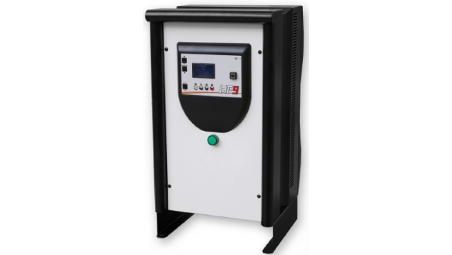
Данная серия трехфазных высокочастотных зарядных устройство oбеспечивает заряд АКБ с жидким электролитом, малообслуживаемых, гелевых, AGM и литий-йонных аккумуляторных батарей.
В HF9 использована не просто привычная высокочастотная технология заряда с частотами 25-50 кГц, а технология SIC-MOSFET, позволяющая работать на частотах до 100 кГц. Это дает возможность трансформатору и другим компонентам зарядного устройства работать с большей эффективностью и меньшим энергопотреблением. В новой конструкции корпуса воздушный поток проходит непосредственно через теплоотводящие каналы по задней части зарядного устройства, предотвращая оседание пыли и образование конденсата на плате управления, что повышает еe надежность и срок службы. Одним из основных преимуществ является упрощение обслуживания и ремонта зарядного устройства. Для упрощения поиска неисправности, существует система самодиагностики, выводящая коды ошибок на дисплей зарядного устройства. А отдельные светодиоды на платах управления позволяют быстро
и безошибочно определить место поломки и устранить проблему.
ТЕХНИЧЕСКИЕ ХАРАКТЕРИСТИКИ
• Трехфазный вариант с питанием 400В переменного тока, частота: 50/60 Гц
• Возможные корректировки под напряжение сети в пределах +/- 15%
• Оптимизированная система охлаждения
• Четкий ЖК-дисплей с дополнительным светодиодом состояния процесса
заряда
• Возможность выбора и настройки параметров кривой заряда
• Отображение кодов ошибок
• Объем памяти 50 последних циклов
• Возможность подключения ПК для считывания статистической информации
• Автоматический плавный старт
• Функции пропорционального и выравнивающего зарядов
• Предохранители на входной и выходной линиях
• В комплекте с силовым и сетевым кабелями (установка коннекторов и
сетевых вилок по запросу)
• Класс защиты — IP 30.
• Металлический корпус
• Температура эксплуатации: от -10 +40 ºC
Характеристики:
| Производитель: | PBM |
| Сила тока, A: | 200 |
|---|---|
| Количество фаз: | 3 |
| Тип зарядного устройства: | Высокочастотное |
| Модель: | HF9 |
| Производитель | PBM (Италия) |
| Тип, серия (модель) | HF9 |
| Напряжение заряда | 48V |
| Зарядный ток | 200А |
| Входное напряжение | 440В |
| Емкость минимальная (7-8 часов) | 1200Ah |
| Емкость максимальная (10-12 часов) | 2000Ah |
| Размеры | 450х360х810 мм |
| Тип: | Зapядные устройства PBM |
Документация:

РАЗДЕЛ 4 – РАБОТА МАШИНЫ
4-10
– Подъемник JLG –
3122454
1. Подключите зарядное устройство к заземленной
розетке.
2. Зарядное устройство аккумуляторной батареи
автоматически включится и выполнит короткое
автотестирование с использованием светодиодных
индикаторов. Все светодиоды будут мигать,
включаясь и выключаясь, в течение двух секунд.
3. Зарядка батарей заканчивается, когда загорается
зеленая лампочка на панели статуса зарядного
устройства батареи.
ПРИМЕЧАНИЕ. Если оставить зарядное устройство
включенным, оно автоматически
повторит полный цикл зарядки при
падении напряжения аккумулятора
ниже установленного предела или
по истечении 30 дней.
Коды неисправности зарядного
устройства
Если во время зарядки возникнет неисправность,
будет мигать красный светодиод «Неисправность»,
обозначая код. Число миганий указывает на
соответствующую ошибку. См. Таблица 4-1, Коды по
числу миганий светодиода зарядного устройства.