

CityCat 2020 не работают круглые счетки по уборке улиц — ChipTuner Forum
![]()
Чип-тюнинг коммерческой техники Кама3, ГАЗ от SMS-Soft
| Прошивки Hyundai SIM2K-24x от Argutin Motors | Прошивки M86 и Гранта M74M от Argutin Motors | Прошивки Kia SIM2K-24x и Bosch ME17.9.21 от Argutin Motors | Прошивки M74-RCO ВАЗ от Владимира Башкирова |
-
Закрытая тема.
-

offline
Авто диагност
- Регистрация:
- 15.06.2007
- Сообщений:
- 146
- Адрес:
- г. Москва
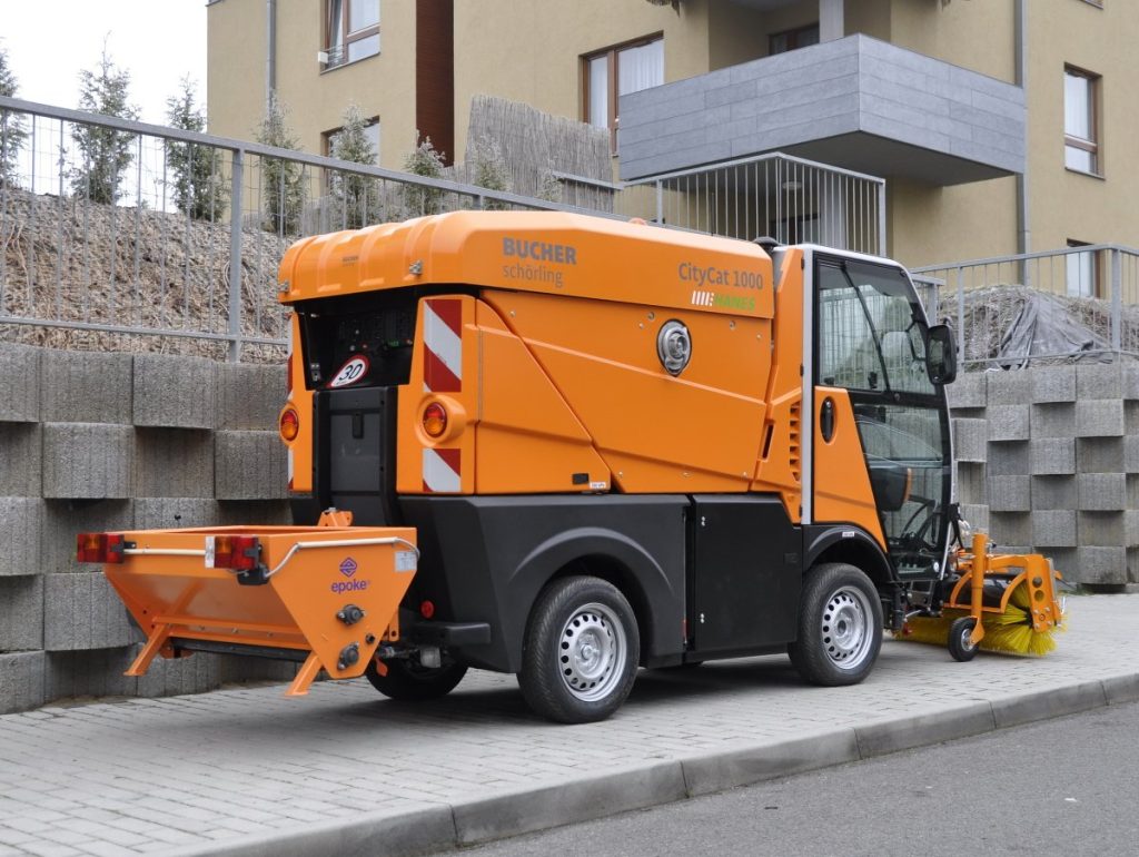
Сам я не сталкивался с этими машинами,но обратились помочь найти неисправность.Суть дела в том ,что после обильной мойки отказал работать джойстик управления круглыми счетками,частично не работает световая электроника,не работает подъем кузова.Подкидывали блок управления,который стоит с переди с праой стороны по ходу движения -не помогло.Есть ошибка на дисплее- неисправность блока управления.Документацию не нашол.Помогите разобраться.
-
offline
Авто диагност
- Регистрация:
- 15.06.2007
- Сообщений:
- 146
- Адрес:
- г. Москва
Про щетки понял,а по сути.
-
offline
Авто диагност
- Регистрация:
- 15.06.2007
- Сообщений:
- 146
- Адрес:
- г. Москва
Предохранители целые.Сушу плату джойстика.
-
offline
Авто диагност
- Регистрация:
- 15.06.2007
- Сообщений:
- 146
- Адрес:
- г. Москва
Сушка платы ничего не дала.Нашел где находится блок управления навесного оборудования,жду донора, попробую подставить.
-
offline
Диагностика, ремонт, ГБО, дизели, бензин
- Регистрация:
- 17.02.2006
- Сообщений:
- 12,764
- Адрес:
- г. Пятигорск, лички нет
Разъёмы все продувать сжатым воздухом, и силиконом или нанопротектом туда брызгать.
Так и не понял, что такое «круглые счётки»…
-
Закрытая тема.
Здесь присутствуют: 1 (пользователей: 0 , гостей: 1)
Текущее время: 08:37. Часовой пояс GMT +4.
Ручной процесс: Процесс ручной диагностики системы через дисплей коды, мигающие коды …
Диагностика: Позволяет считывать ошибки в памяти ECU предоставляя пользователю информацию о кодах ошибок обнаруженных в нем. Эта функция позволяет пользователю осуществлять удаление ошибок из памяти, логически, если ошибка присутствует, то она снова будет обнаружена в ECU и будет отображаться при следующей диагностике.
Измерение Величин: Отображение на экране значений различных датчиков, подключенных к ECU. Зависит от каждой системы.
Активация Компонентов: Это прямые тесты, которые можно сделать с помощью компонентов системы. Например, активировать модулятор ABS, активируйте соленоидные клапаны подвески для того, чтобы поднять или опустить шасси, … Это активная диагностика, которая, например для двигателя, позволяет проводить испытания калибровки его состояния, такие как как балансировка цилиндров, компрессию и т. д. Зависит от каждой системы.
Данные ECU: Это технические данные ECU, серийный номер, версия программного обеспечения, референция производителя и т.д. Зависит от каждой системы.
Параметры: Некоторые ECU могут работать с различными конфигурациями. С помощью этой опции Вы можете скопировать конфигурацию и параметры блока управления, таким образом блоки управления могут быть запрограммированы при их первой установке. Для некоторых систем допускаются даже изменение некоторых параметров, не влияющих на безопасность транспортных средств.
Калибрование: Некоторые системы требуют калибровку некоторых компонентов для их правильной работы. Лучшим примером являются электронные подвески, в которых должны храниться контрольные значения, так что бы ECU мог правильно работать.
Сброс: Этот пункт относится к сбросу счетчиков блоков управления обслуживания . Если обслуживание операций сделано, но сигнал обслуживания не отменяется, предупреждающее сообщение относительно обслуживания будет активным. Ничего общего с удалением кодов ошибок памяти, которые являются частью диагностики.
Технические данные системы: Техническая информация о системе с указанием проверки значений, описаний, графиков, диаграмм …
Электрическая Схема: Подробная схема системы, содержащая дополнтительную информацию о конфигурации, комплектующих, местоположении и заметках, которые делают диагностику проще.
Технические Данные о Транспортном Средстве : Техническая информация o транспортных средствах, включая все технические данные по моторизации, моменты затяжки, мощности, графики и другие проверочные значения …
Эксплуатация транспортного средства : Раздел, в котором отображаются интервалы технического обслуживания с указанием операций, которые будут выполняться с транспортным средством, и через который можно получить отчёты, что упрощают учёт клиентов мастерской.
V20 series
One
revolutionary
series
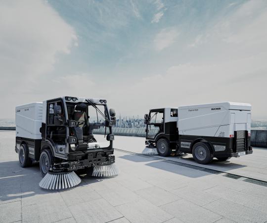
Bucher Municipal is about to revolutionise the world of street cleaning with the all new series of 2 m³ compact CityCat sweepers.
With a choice of sizes, configurations and all-electric options, welcome to improved suction, enhanced connectivity, increased comfort and ever-important sustainability.

CityCat V20 & CityCat V20e
CityCat V20 & CityCat V20e
- Articulated steering for great manoeuvrability
- Floating suction intake with patented hanging mechanism and straight suction hose
- Unique HMI for intuitive and comfortable operation
- Big water & hopper volume for greatest autonomy
- Single wheel suspension for unparalleled driving comfort
- High payload of up to 2100 kg at 4800 kg GVW
- Euro 6d for minimum environmental impact
- Customized, 63 kWh Bucher Battery Pack for zero emission
- Bucher Connect for service and fleet management with ease
CityCat VS20 & CityCat VS20e
CityCat VS20 & CityCat VS20e
- 3.5 t gross vehicle weight for increased accessibility
- Drivable with a class B (car) driver’s license
- Adaptable for the simplest application up to high-end sweeping
- Up to 1 tone payload, combined with a 2 m³ hopper and 425 l water for maximum autonomy
- Stage V engine for low environmental impact and lowest maintenance costs
- Customized, 45 kWh Bucher Battery Pack for zero emission
- Bucher Connect for service and fleet management with ease
Innovation at its best
Future-proof drive system
Unmatched sweep performance
Operation at your fingertips
Future-proof drive system
(Double click for full screen)
Unmatched sweep performance
(Double click for full screen)
Operation at your fingertips
(Double click for full screen)
Подметально-уборочная машина BUCHER, в том числе — CITYCAT 2020, очень надежная техника и редко подводит. Но даже и у нее иногда случаются поломки. Бывает очень неприятная ситуация, когда двигатель BUCHER заглох и не хочет заводиться. При этом на дисплее панели приборов горит сообщение с соответствующим описанием кода ошибки неисправности. Но бывают и исключения, когда ошибки не высвечиваются. Специалистами нашей компании накоплен солидный опыт по диагностике и ремонту описываемых неисправностей. Есть два кардинально различных вариантов «незапуска» двигателя:
- При повороте ключа в замке зажигания, стартер прокручивает двигатель экскаватора
- Стартер не включается и не крутит двигатель
Постараюсь более подробно рассказать про каждый из вариантов неисправности техники.

Запуск двигателя на выезде
Специалистами нашего предприятия накоплен огромный опыт оказания услуг по запуску двигателя BUCHER, когда уборочная техника заглоха при выполнении работ. У нас имеются автомобили техпомощи, опытные мастера готовые в любой момент приехать на помощь. Специализированное диагностическое оборудование.
Не крутит стартер BUCHER
Если система управления вышеуказанной техники при повороте ключа зажигания на старт, не включает стартер, то причина поломки заключается в электрическом оборудовании или электронных системах грузовика. Причины могут быть следующие:
- Неисправность блока реле и предохранителей
- Отсутствие контактов в разъемах электропроводки
- Неисправность главного реле грузового автомобиля
- Выход из строя замка зажигания Выход из строя стартера
- Обрыв или замыкание шины КАН
- Отсутствие “массы”
- Отсутствие напряжения питания на блоке управления двигателем
- Обрыв или замыкание жгута проводки
- Неисправность втягивающего реле стартера
- Выход из строя замка зажигания
- Выход из строя блока управления двигателем

Стартер крутит — не заводится
Если стартер описываемой техники при повороте ключа в замке зажигания крутится, но при этом мотор не подает никаких признаков. Причина неисправности может заключаться как в электрооборудовании автомобиля, так и в механике. Неисправности автоэлектрики могут быть как описанные выше, кроме неисправностей связанных со стартером и его цепями, плюс следующие причины:
- Неисправность топливного насоса высокого давления (ТНВД)
- Механическая поломка двигателя
- “Завоздушивание“ топливной аппаратуры
- Неисправность иммобилайзера
- Отсутствие солярки в баке
- Засорение топливного фильтра
- Неисправность чипа в ключе
- Засорение топливопроводов
- Поломка обратного клапана
- Механические неисправности форсунок
Теги: глюканул монитор управления оборудованием bucher cityfant 6000
Bucher Municipal
Software Updates
Bucher Municipal
Software Updates
Software Updates
Street Sweepers
Keeping the control software up to date will ensure that the sweeper benefits from all of the latest user functions and improvements.
-
DON’T USE for the V65T — VT652 REV AA — DON’T USE for the V65t
-
V Range Technical Bulletin
V Range Software Update Computer Download Instructions
V Range Software Update Instructions — JVM inside the cab
CityCat 5006 Software Updates
CityCat 5006 Software Update Instructions
-
Instructions — CityCat 5006 Software Update
-
CityCat 5006 NOVEMBER 2020
CityCat 5006 Software Update Computer Download Instructions
CityCat 5006 Software Update Instructions — inside the cab
-
Contents
-
Table of Contents
-
Bookmarks
Quick Links
Installation and startup guide
Issue: 08.08
C−LRV Lift Control Valve, Size 175 / 350 / 700
NTA−2 power supply unit and C−DELCON
Reference: 300−I−9010212−E−10/08.08
Classification: 450.500.500
1/92
Summary of Contents for Bucher C-LRV Series
-
Page 1
Installation and startup guide Issue: 08.08 C−LRV Lift Control Valve, Size 175 / 350 / 700 NTA−2 power supply unit and C−DELCON Reference: 300−I−9010212−E−10/08.08 Classification: 450.500.500 1/92… -
Page 2
Because the products are subject to continual improvement, we reserve the right to amend the product specifications contained in this catalogue. The original language and legal terminology of all Bucher Hydraulics AG documentation is exclusively German. Bucher Hydraulics AG cannot be held liable for any possible errors in translation. -
Page 3: Table Of Contents
C−LRV lift control valve Content Page …………….General .
-
Page 4
C−LRV lift control valve ……….. . . Installation and commissioning . -
Page 5: General
C−LRV lift control valve General This guide is an integral part of the product. It describes the product´s safe use in all phases of operation and is valid for all model series that are referred to. Target group S Operator S Installer S Service engineer S Repair technician…
-
Page 6
C−LRV lift control valve 300−I−9010212−E−10/08.08 6/92… -
Page 7: Product Description
C−LRV lift control valve Product description Product description Important notes 1.1.1 Subassemblies This guide differentiates between the following subassemblies: C−LRV lift control valve C−DELCON electronic control card NTA−2 power supply unit 300−I−9010212−E−10/08.08 7/92…
-
Page 8: Intended Use
C−LRV lift control valve Product description 1.1.2 intended use Lift control valve for operating hydraulically−driven passenger and goods lifts. The products must not be handled in any way by unauthorised persons. 1.1.3 Conformity The product was designed and developed in conformity with the follow- ing standards: Standards EN 81−2…
-
Page 9: Product Identification
C−LRV lift control valve Product description Product identification 1.2.1 Nameplate 1 Valve type = C−LRV 175 2 Flow rate UP = 120 l/min 3 Flow rate DOWN = 150 l/min 4 Minimum static pressure (empty car) = 21 bar 5 Maximum static pressure (full car) C−LRV 175 −…
-
Page 10: Model Code
C−LRV lift control valve Product description 1.2.3 Model code C−LRV 175 R 250 K 251 Valve type/size = C−LRV 175 = C−LRV 350 = C−LRV 700 Flow range: flow rate/type C−LRV 175 15–45 l/min = R 45 46–90 l/min = R 90 91–250 l/min = R 250 C−LRV 350…
-
Page 11: C−Lrv Lift Control Valve
C−LRV lift control valve Product description C−LRV lift control valve Legend Maximum−pressure setscrew Flow−rate measuring system Bypass−pressure setscrew Emergency−lowering valve Pressure−relief valve DOWN spool Pilot filter Check valve Test point, G½ UP spool Pressure gauge UP damping jet Pressure gauge shut−off screw DOWN damping jet Air−bleed screw Ball valve…
-
Page 12: Simplified Hydraulic-Electrical Diagram
C−LRV lift control valve Product description 1.3.1 Simplified hydraulic–electrical diagram Legend Pressure−relief valve DOWN spool Test point, G½ Check valve Pressure gauge UP spool Pressure gauge shut−off screw Pipe−rupture valve Feedback sensor Ball valve (non−contacting) Electrical emergency−lowering Main filter valve (optional) Flow−rate measuring system Pressure switch Emergency−lowering valve…
-
Page 13: Factory Settings
C−LRV lift control valve Product description 1.3.2 Factory settings All valves are factory−set to the values for the particular installation and then tested. S Pressure−relief valve set to the maximum working pressure S Bypass pressure as per the calculated minimum static pressure S Mechanical null point of the feedback sensor S Emergency−lowering valve set to 5−10 % of maximum DOWN speed 1.3.3…
-
Page 14
C−LRV lift control valve Product description 2. DOWN section / emergency−lowering valve The down section is constructed in a similar way to the up section. S Initial position: DOWN spool (14) is closed leak−free in the 0 position S Down travel / acceleration: DOWN spool (14) is progressively opened by the electro−proportional valve (DOWN solenoid);… -
Page 15
C−LRV lift control valve Product description 3. Flow−rate measuring system S The oil flows through the flow meter (12) in both the up and down directions S The baffle−disc is displaced axially as a function of the flow rate S This axial displacement is converted by a non−contacting feedback transducer (10) into an electrical DC signal (the feedback signal), which is then sent to the C−DELCON S The output signal (the feedback) is proportional to the flow rate… -
Page 16: Technical Data
C−LRV lift control valve Product description 1.3.4 Technical data Legend Flow−rate measuring system Pressure−relief valve DOWN solenoid UP solenoid View A Pressure switch port Orientation of Z port Pressure switch port (specify when ordering!) Hand pump port rear (standard) Pump port left Tank port right…
-
Page 17
C−LRV lift control valve Product description Type Ports Ports Weight Max. press. Z, T, P Z1, Z2, Z3 [kg] [bar] C−LRV 175 G¼ C−LRV 350 G1½ G¼ C−LRV 700 G2, G2½, G2 G¼, G¼, G 22.5 Type Dimensions [mm] C−LRV 175 C−LRV 350 C−LRV 700 Type… -
Page 18: Pressure Drop
C−LRV lift control valve Product description 1.3.5 Pressure drop C−LRV 175 R250 Flow ring (R) 15.0 12.5 10.0 Spool K 251 DOWN (Z−T) Spool K 91 UP (P−Z) C−LRV 350 R500 Flow ring (R) 15.0 12.5 10.0 DOWN (Z−T) Spool K 501 UP (P−Z) Legend Pressure drop [bar] Min.
-
Page 19
C−LRV lift control valve Product description C−LRV 700 R1000 Flow ring (R) 12.5 DOWN (Z−T) Spool K 1001 UP (P−Z) 1000 Legend Pressure drop [bar] Min. required dyn. pressure Flow rate Q [l/min.] 300 cSt (HLP 46) 75 cSt (HLP 46) 300−I−9010212−E−10/08.08 19/92… -
Page 20: C−Delcon Electronic Card
C−LRV lift control valve Product description C−DELCON electronic card The C−DELCON controls the oil flow − and therefore the lift’s travel pro- file − in accordance with a preset curve. Attention Electrostatic discharge (ESD) The C−DELCON can be damaged by incorrect handling. Always keep the DELCON in its ESD protective bag and only hold it by the spacer studs (4).
-
Page 21: Description Of Function
C−LRV lift control valve Product description 1.4.2 Description of function S The lift control system sends the command signals to the C−DELCON via potential−free relay contacts or semiconductors (K1−K4) S The feedback value is compared with the demand travel curve throughout the whole travel.
-
Page 22: Technical Data
C−LRV lift control valve Product description 1.4.3 Technical data Weight: 150 g General description S Digital electronic card for the C−LRV valve S Conforms to the European format (100 mm x 160 mm) S Enhanced ride comfort S Automatic reduction of demand signal if nominal speed is not at- tained S Extended functions S Simple set−up…
-
Page 23: Travel And Switching Diagram For Normal Travel Distance
C−LRV lift control valve Product description 1.4.4 Travel and switching diagram for normal travel distance * motor run−on time of 0.5 … 1 s Y−Δ Y starting time of up to approx. 3 s with Y−Δ, ** Drop−out delay of 0.5 … 1 s K1 and K2 not until Δ…
-
Page 24: Travel And Switching Diagram For Short Travel Distances
C−LRV lift control valve Product description 1.4.5 Travel and switching diagram for short travel distances The electronics of the C−LRV valve make it possible to control stops at mezzanines and similar short travel distances with the same ride comfort as in normal travel. Important: The maximum speed should be reduced to a value that, despite the short travel distance, can actually be attained.
-
Page 25
C−LRV lift control valve Product description S By using relays K6, K7 or K8, various reductions in the nominal speed can be achieved (e.g. for different floor spacings) S The speed reduction can be adjusted between 20–100 % of nominal speed S Speed can be set by means of parameter «K6 speed»… -
Page 26: Nta−2 Power Supply Unit
C−LRV lift control valve Product description NTA−2 power supply unit The NTA−2 power supply unit provides both power supply and physical support for the C−DELCON. Legend Mains voltage terminals Terminal block for emergency power supply Socket for feedback cable Jumper JP1 (demand/feed- Terminal block back monitoring −…
-
Page 27: Description
C−LRV lift control valve Product description 1.5.1 Description The power supply unit is connected directly to the main supply or the control system supply. The control signals for the C−DELCON are connected to the terminal block (3). Through the terminals 18–17a (N.O. make contact) 18–17b (N.C.
-
Page 28: Technical Data
C−LRV lift control valve Product description 1.5.2 Technical data 8 12 151.7 Weight 0.675 kg Mains voltage NTA−2/115 100/(110)115/120 VAC NTA−2/230 220/230/240 VAC ±10 % NTA−2/400 380/(400)415/440 VAC Frequency 50/60 Hz ±10 % Power consumption 20 W during travel, approx. 8 W at standstill EMC standards EN−50081, EN−50082, EN−50011/22, IEC 1000−4 Protection class…
-
Page 29: Terminal Assignments
C−LRV lift control valve Product description 1.5.3 Terminal assignments L1c/L2c L1b/L2b L1a/L2a N/L1 Legend Control signals Demand / feedback monitoring Connection for feedback cable Emergency power supply Mains voltage connection Terminal Description Mains Voltage Connection NTA−2/115 NTA−2/230 NTA−2/400 N/L1 Neutral (N) Neutral (N) Phase (L1) L1a/L2a*…
-
Page 30
C−LRV lift control valve Product description Terminal Description Control signals K1 Fast UP K2 Slow UP K3 Fast DOWN K4 Slow DOWN K5 Inspection speed K6 Speed reduction (auxiliary speed) K7 Speed reduction (auxiliary speed) K8 Speed reduction (auxiliary speed) Ground/reference potential (GND) for command inputs (K1…K8) Ground/reference potential (GND) for command inputs (K1…K8) Common, DOWN solenoid… -
Page 31: Iwk−1 Feedback Cable
C−LRV lift control valve Product description IWK−1 feedback cable Important: The feedback cable must be run from the lift control valve directly to the NTA−2 power supply unit without any intermediate ter- minals. Any discontinuity in the feedback cable (break, kink, etc.) can endanger trouble−free operation.
-
Page 32: Surroundings
C−LRV lift control valve Product description Surroundings For reliable operation, the following conditions must be maintained in the surroundings: Surroundings Requirement 2…40 °C Machine room tempera- ture 2…60 °C Oil temperature Relative air humidity max. 90 % (non−condensing) Emissions The following emissions can occur during operation: Emission Corrective action / Note Heat…
-
Page 33: Safety Information
C−LRV lift control valve Safety information Safety information It is essential to take note of the important safety information contained in this document (guide). Attention Denotes a potentially harmful situation. If it is not prevented, the pro- duct or its surroundings may be damaged. Caution Denotes a potentially dangerous situation.
-
Page 34
C−LRV lift control valve Safety information 300−I−9010212−E−10/08.08 34/92… -
Page 35: Operating Controls And Indicators
C−LRV lift control valve Operating controls and indicators Operating controls and indicators Description Tools Maximum−pressure setscrew 1 x open−ended spanner, 13 A/F mm (Screw À) Allen key, 4 mm A/F Bypass−pressure setscrew Open−ended spanner, 10 A/F mm (Screw Á) Allen key, 5 mm A/F Pressure gauge shut−off screw Allen key, 4 mm A/F Filter screw, UP…
-
Page 36: Emergency−Lowering Valve
C−LRV lift control valve Operating controls and indicators Emergency−lowering valve Pressing lever = lowering the car The car is lowered by pressing the lever of the emergency−lowering valve. Important: The minimum preload pressure of 6–10 bar continues to exist (prevents slack−rope build−up as per EN 81−2) Danger Car descent People may suffer injury and materials may be…
-
Page 37: Handterminal
C−LRV lift control valve Operating controls and indicators Handterminal Keys Demand values menu Options menu Null point display Menu − Information ↑ Steps to previous parameter ↓ Steps to next parameter Increases the value of the current parameter − Decreases the value of the current parameter General description S Easy set−up of the travel curve…
-
Page 38
C−LRV lift control valve Operating controls and indicators Description of function S By pressing any of the keys 1 to 4, the C−DELCON switches into parameterisation mode. No travel is possible; the green RUN LED on the C−DELCON goes out S Select the desired parameter using the ↑… -
Page 39
C−LRV lift control valve Operating controls and indicators Password The C−DELCON’s parameters and functions can be password−protected. The password consists of four numbers. Password 0000″ means that password protection is not activated (this is the factory setting). The password is entered one number at a time: S Increase the value with the + key, decrease it with the −… -
Page 40
C−LRV lift control valve Operating controls and indicators e.g. Display during travel K1−K8 1100 0000 S 1st line: status of command inputs K1 to K8 C: +3.45 F: +4.18 no command command is present S 2nd line: existing control voltage (C) and feedback value (F) in volts e.g. -
Page 41: Windelta32 − Pc Program
C−LRV lift control valve Operating controls and indicators WinDelta32 − PC program Software, adapter and cable can be ordered as Part No. 7010867 The software can be downloaded free of charge from: http://www.bucherhydraulics.com 3.4.1 General description Parameterisation S C−DELCON parameters can be read off and set via PC S Parameter sets can be saved S Comments can be added to parameter sets S Print function…
-
Page 42: Pc Requirements
C−LRV lift control valve Operating controls and indicators 3.4.2 PC requirements S Operating system: Windows 95/98/ME/NT/2000/XP/Vista S Processor: 133 MHz or faster S RAM: 32 MByte S Free hard disc space: min. 10 MByte for the program and min. 5 MByte for saving curves S Serial port (RS232, 19200 Baud) 3.4.3…
-
Page 43
C−LRV lift control valve Operating controls and indicators Removing the old version: Exit and close all programmes Remove the old version of WinDelta32 (refer to the Windows help for information about how to remove a programme) Installing the new version (the following steps may take a few minutes): Navigate to the installation file Install_WinDelta32_1pXX_EN.exe (XX = programme version) either by clicking the Windows Start but- ton and selecting Run then Browse, or by using the Windows Ex-… -
Page 44
C−LRV lift control valve Operating controls and indicators If you wish to reuse the parameter sets that you previously exported: Select the menu Parameters/LRV and import (click Import => All parameter sets) the stored file (e.g. the file Para_LRV.prm from the folder C:Temp) Click the button (Refresh data) -
Page 45: Connect Delcon To Pc / Laptop
C−LRV lift control valve Operating controls and indicators 3.4.4 Connect DELCON to PC / Laptop Possibilities for connecting DELCON to PC / Laptop Never connect DELCON to an Ethernet port! 300−I−9010212−E−10/08.08 45/92…
-
Page 46
C−LRV lift control valve Operating controls and indicators Connecting to serial port using Bucher adaptor Connecting to USB port using a USB−RS232 converter (with Bucher adaptor) 300−I−9010212−E−10/08.08 46/92… -
Page 47: Installation And Commissioning
C−LRV lift control valve Installation and commissioning Installation and commissioning Installation Orientation of the ball−valve outlet As standard, the ball−valve outlet is rear−facing (code H) Alteration to left (L) or right (R) is possible. Important: the ball−valve outlet must not be turned to a new position unless the hose is first disconnected.
-
Page 48: Assembly
C−LRV lift control valve Installation and commissioning Assembly 4.2.1 Hose or pipe Caution Contamination in the line Contamination adversely affects the valve’s function. This can lead to a dangerous system condition. Preventive measures: S Clean the hose or pipe before fitting it S Leave sealing caps/plugs in place until assembly S Check that all fittings are assembled correctly 4.2.2…
-
Page 49: Wiring The Power Supply Unit
C−LRV lift control valve Installation and commissioning 4.2.3 Wiring the power supply unit Legend Fast UP Slow UP Fast DOWN Slow DOWN Inspection speed Speed reduction Speed reduction Speed reduction 6a/6b Common DOWN solenoid UP solenoid Stabilised voltage supply +15 V Feedback signal (input) Stabilised voltage supply…
-
Page 50: Electrical Emergency−Lowering 2 X 24 Vdc
C−LRV lift control valve Installation and commissioning 4.2.4 Electrical emergency−lowering 2 x 24 VDC Important: the operator must undertake any further measures required to ensure short−circuit and overvoltage protection. If a mains (line) failure occurs, the power supply unit can be powered by an external battery supply (2 x 24 V) through terminals 12, 19 and 20.
-
Page 51: Electrical Emergency−Lowering 1 X 12 Or 1 X 24 Vdc (Option)
C−LRV lift control valve Installation and commissioning 4.2.5 Electrical emergency−lowering 1 x 12 or 1 x 24 VDC (option) Warning Do not activate the electrical emergency−lowering valve unless the safety circuit is closed! In an emergency the lift car can be lowered by operating the emergency lowering valve electrically.
-
Page 52: Commissioning/Settings
C−LRV lift control valve Installation and commissioning Commissioning/settings 4.3.1 Checking the test numbers S The valve test number is stamped on the body (below the manual emergency−lowering valve) ⇒ 1.2.2. S The C−DELCON test number is on a label on the connector ⇒ 1.4. Important: always quote the test number when making enquiries.
-
Page 53: The Bypass Pressure Setting
C−LRV lift control valve Installation and commissioning 4.3.3 The bypass pressure setting Important: the car must be empty Setting the bypass pressure with the Handterminal (car out of sight) Set the «SIU Type» parameter in the C−DELCON to «Off» make a note of the existing setting ⇒…
-
Page 54
C−LRV lift control valve Installation and commissioning Setting the bypass pressure with a pressure gauge (car out of sight) Set the «SIU Type» parameter in the C−DELCON to «Off» make a note of the existing setting ⇒ Page 71, Section 5.1.4.2 Read the minimum static pressure on the pressure gauge Close the ball valve Press emergency−lowering lever (vents pressure in the valve) -
Page 55
C−LRV lift control valve Installation and commissioning Setting the bypass pressure with the car in sight Set the «SIU Type» parameter in the C−DELCON to «Off» make a note of the existing setting ⇒ Page 71, Section 5.1.4.2 Remove the UP solenoid plug (10) Slacken the locknut for bypass−pressure setscrew (2) Unscrew bypass−pressure setscrew (2) approx. -
Page 56: The Maximum Pressure Setting
C−LRV lift control valve Installation and commissioning 4.3.4 The maximum pressure setting Adjusting the maximum pressure Set the «SIU Type» parameter in the C−DELCON to «Off» make a note of the existing setting ⇒ Page 71, Section 5.1.4.2 Close the ball valve Press emergency−lowering lever Slacken the locknut for screw (1) Turn screw (1) approx.
-
Page 57: Speed−Monitoring In The Door Zone, Siu−4
C−LRV lift control valve Installation and commissioning 4.3.6 Speed−monitoring in the door zone, SIU−4 The SIU−4 function monitors the speed in the door zone and during relevelling. If the speed setting is exceeded, the lift is stopped (per EN 81−2, max. 0.3 m/s) S When the speed setting is exceeded, the relay activates S The speed can be set with the Handterminal or PC software 4.3.7…
-
Page 58: Positioning The Shaft Switches For The Deceleration Distance
C−LRV lift control valve Installation and commissioning 4.3.8 Positioning the shaft switches for the deceleration distance The spacing of the shaft switches depends on the car speed ⇒ 4.3.9 Aux. speed e.g. v=50 % v=50 % v=100 % v=100 % X Deceleration distance (shaft switches) for maximum speed Y Deceleration distance (shaft switches) for auxiliary speed (for example, 50 % of maximum speed;…
-
Page 59: Required Deceleration Distance
C−LRV lift control valve Installation and commissioning 4.3.9 Required deceleration distance Guidelines for positioning the deceleration switches. Examples Deceleration distance «X» for direct (1:1) drive e.g.: v=0.4 m/s → x =0.4 m Deceleration distance «X» for indirect (2:1) drive e.g.: v=0.63 m/s → x =0.71 m Deceleration distance «Y»…
-
Page 60: Setting The Mechanical Null Point
C−LRV lift control valve Installation and commissioning 4.3.10 Setting the mechanical null point The null point is factory−set. With Handterminal, see This can be checked with the Handterminal (or PC). If, on commission- Page 37, Section 3.3 ing, the reading is outside the range ±0.05V, then the null point must be reset.
-
Page 61: Pilot Filters
C−LRV lift control valve Installation and commissioning 4.3.11 Pilot filters Filter−strainers are positioned upstream of the lowering and lifting valves in accordance with the international standards for lifts. The filters are easily accessible from outside the valve. Caution Contamination in valve (filter) This can cause leakage.
-
Page 62: The Pipe−Rupture Valve Test
C−LRV lift control valve Installation and commissioning 4.3.12 The pipe−rupture valve test A precondition for testing the pipe−rupture valve is that the lift must be working properly, without any faults. Danger Uncontrolled descent (free fall) People may suffer injury and materials may be damaged. Before testing the pipe−rupture valve, make sure that there are no people or materials in the lift shaft.
-
Page 63
C−LRV lift control valve Installation and commissioning Testing the pipe−rupture valve (for C−DELCON software version 2.110 or higher) On the Handterminal, select the Pipe rupture» function in the In- formation (4) menu under Commands» ⇒ Page 76, Section 5.1.4.4 Press and hold the + key on the Handterminal; the «DOWN» LED on the C−DELCON will start to flash Send DOWN command Wait until the car is accelerating… -
Page 64
C−LRV lift control valve Installation and commissioning Testing the pipe−rupture valve (up to C−DELCON software version 2.100 or with WinDelta32 PC program) Set the «SIU Type» parameter in the C−DELCON to «Off» make a note of the existing setting ⇒ Page 71, Section 5.1.4.2 Set the «Demand val. -
Page 65: Operation
C−LRV lift control valve Operation Operation Handterminal 5.1.1 Parameter overview Handterminal Demand values (1) Options (2) Hall sensor (3) Informationen (4) ⇒ 5.1.4.1 ⇒ 5.1.4.2 ⇒ 5.1.4.3 ⇒ 5.1.4.4 Demand Demand Commands Information list values UP values DOWN − Start speed −…
-
Page 66: Overview Of Travel Curve
C−LRV lift control valve Operation 5.1.2 Overview of travel curve Legend Start speed Demand signal Acceleration Control voltage (prop. sol.) Fast speed Deceleration Slow speed Soft−Stop (steepness) Minimum pressure / offset sol. 5.1.3 Overview of control parameters (PID) Dynamic Static Dynamic P sol.
-
Page 67: Description Of Parameters
C−LRV lift control valve Operation 5.1.4 Description of parameters 5.1.4.1 Demand values Up / Down (1) Setting «Start speed» S Higher value: faster starting speed, shorter starting time, harsher start−up jolt S Setting range: 0.05–0.50 V S Standard: 0.30 V Important: low settings for «Start speed»…
-
Page 68
C−LRV lift control valve Operation Setting «Fast speed» S Higher value: faster travel speed S Setting range: 1.00–10.00 V S Standard: 7.00 V S Example of litres <=> volts conversion, ⇒ Page 79 Setting «Deceleration» S Higher value: greater deceleration, i.e. shorter deceleration distance S Setting range: 0.30–5.00 V/s S Standard:… -
Page 69
C−LRV lift control valve Operation Setting «Relevelling» S Operative during fine adjustment S Higher value: faster travel speed S Setting range: 0.20–1.50 V S Standard: 0.40 V Important: low settings for «Relevelling» may cause slow travel to be uneven due to static friction in the cylinder and car guides Important: low settings for «Relevelling»… -
Page 70
C−LRV lift control valve Operation Setting «P sol. dynamic» S Operative in dynamic control processes (acceleration, deceleration) S Higher value: higher solenoid control gain S Setting range: 0.20–1.50 S Standard: 0.80 DOWN 0.70 Important: high settings may cause oscillations. Setting «I sol. dynamic» S Operative in dynamic control processes (acceleration, deceleration) S Higher value: longer solenoid reset time, greater control error in dynamic processes… -
Page 71
C−LRV lift control valve Operation 5.1.4.2 Options menu (2) Setting «Valve type» S Selection of valve type S Overwrites the current control parameters (PID) with the factory settings for this valve S Setting range: − C−LRV 175 − C−LRV 350 −… -
Page 72
C−LRV lift control valve Operation Setting «SIU−1 difference» S Demand/feedback difference − only operative when SIU−1 is activated S Setting range: 20–50 % of fast travel speed S Standard: 25 % Setting «SIU−4 threshold» S Feedback threshold − only operative when SIU−4 is activated S Setting range: 2.0–5.0 V S Standard:… -
Page 73
C−LRV lift control valve Operation Setting «K6/K7/K8 acceleration» S Only operative with auxiliary speeds (K6, K7, K8) S Higher value: greater acceleration, i.e. shorter acceleration distance S Setting range: 0.30–5.00 V/s S Standard K6: 0.80 V/s S Standard K7: 1.20 V/s S Standard K8: 1.60 V/s Setting «K6/K7/K8 speed»… -
Page 74
C−LRV lift control valve Operation Setting «Demand val. red.» S Setting the sensitivity of the automatic demand−signal reduction S Standard: Normal S Functions − Off − Few sensitivity − Normal − Sensitive Setting «Start delay» S Pause between command and start of travel S Higher value: longer pause S Setting range: 0.1–1.0 s… -
Page 75
C−LRV lift control valve Operation Setting «Command input» S Selection of command evaluation S Standard: Bucher K1 … K8 S Setting range: − Bucher K1…K8 − ELRV K1…K8 − binary B1…B4 − 3 Sign. K1…K8 Important: On the control side it must be guaranteed that a command change is concluded within 20 ms Bucher K1…K8… -
Page 76
C−LRV lift control valve Operation 5.1.4.3 Null point / Hall sensor menu (3) S Displays the current feedback value 5.1.4.4 Information menu / Commands» (4) Setting «Language/Sprache» S Selection of the user language S Possible languages − German − English −… -
Page 77
C−LRV lift control valve Operation 5.1.4.5 Information menu / Information list» (4) Errors / Warnings / Info For explanation of errors, S Fault memory for the last 8 faults, with operating−hours count see Page 84 «Software version» S Software version S Example: 2.130 «Hardware version»… -
Page 78
C−LRV lift control valve Operation «Drive down» S Number of Down travels S Max. 1.3 million Important: Relevelling Down operations are not counted «Operation hour» S C−DELCON operating−hours counter S Max. 65535 hrs «+ unstab voltage» Positive unstabilised voltage from the power supply unit S Range: +17 … -
Page 79: Calculating The Demand Values For Maximum Speed
C−LRV lift control valve Operation Calculating the demand values for maximum speed The demand values are shown on a label on the C−DELCON’s microprocessor The demand values for the maximum UP and DOWN speeds can be calculated from the following table: Valve type Flow range, Q Flow ring…
-
Page 80: Faults / Fault−Finding
C−LRV lift control valve Operation Faults / Fault−finding 5.3.1 Check list for fault correction Fault Cause Corrective action Page (Chapter) S Motor / pump not running S Check connection No UP travel S Wiring fault S Check wiring 49 (4.2.3) S Electrics −…
-
Page 81
C−LRV lift control valve Operation Fault Cause Corrective action Page (Chapter) S Mechanical null point is S Check 60 (4.3.10) displaced S Plunger cylinder is at S Cylinder pillar is too short end−stop S Check cylinder stroke S Extension of telescopic S Check cylinder stroke cylinder is not S Telescopic cylinder is… -
Page 82
C−LRV lift control valve Operation Fault Cause Corrective action Page (Chapter) S Hydraulic line to the S Fit larger line cylinder is too small S Oil is too cold S Use multigrade oil S Install oil heater S Provide parking circuitry S Too much friction in S Align cylinder and rails system… -
Page 83
C−LRV lift control valve Operation Fault Cause Corrective action Page (Chapter) S DOWN pilot pin is bent S Exchange DOWN pilot valve S Emergency−lowering S Operate it several times 36 (3.1) Attention valve leaking during UP command¨ The UP and DOWN spools are not S Check valve is leaking S Replace seal… -
Page 84: Fault Description
C−LRV lift control valve Operation 5.3.2 Fault description Display on Further de- Cause Remedy tails (code, Handterminal see 5.3.3) Err:None No fault Warn: Temperature of C−DELCON ex- Warning message, not a fault 102, 301, ceeds 70 °C Board−T. S Ambient temperature is too high S Lower the ambient temperature S Poor ventilation in control cabinet S Improve control cabinet ventila-…
-
Page 85
C−LRV lift control valve Operation Display on Further de- tails (code, Cause Remedy Handterminal see 5.3.3) Warn: Null point outside of ±0.20 V Warning message, not a fault 103, 301, 0 Point S Mechanical null point is wrongly S Reset the mechanical null point S Bypass pressure is too high S Set the bypass screw on the valve correctly (unscrew it… -
Page 86
C−LRV lift control valve Operation Display on Further de- tails (code, Cause Remedy Handterminal see 5.3.3) Warn: Automatic null point adjustment Warning message, not a fault 103, 105, Bypass pre outside of +0.20 V 301, 401 S Hand pump activated S Bypass pressure is too high S Set the bypass screw on the 103, 105,… -
Page 87: Code For Further Details
C−LRV lift control valve Operation 5.3.3 Code for further details Code Meaning Monitoring Constantly At standstill At start of travel During travel Not monitored during inspection travel When the program is started Dependent on parameterisation Effect Travel is disabled Travel is aborted (relay is opened) Travel is aborted (relay is NOT opened) Travel is aborted (dependent on parameterisation, relay may be opened) Save…
-
Page 88
C−LRV lift control valve Operation 300−I−9010212−E−10/08.08 88/92… -
Page 89: Maintenance
C−LRV lift control valve Maintenance Maintenance Maintenance schedule This service plan is just a guide. Adjustments or changes should be un- dertaken by the installation company. Work to be carried out Time Valve Check internal leakage Check external leakage Check the maximum pressure setting (pressure−relief valve / screw) Check mechanical null point (Hall sensor) Clean pilot filters…
-
Page 90: Operating Materials And Aids
C−LRV lift control valve Maintenance Operating materials and aids Hydraulic oil (code) Viscosity Permissible temperature range [mm2/s] (cSt) to DIN 51525 to ISO 6074 at 40 °C min. °C max. °C H−LP 32 ISO VG 32 H−LP 46 ISO VG 46 * H−LP 68 ISO VG 68 H−LP 100…
-
Page 91: Installation Guide For Down Pilot Valve
C−LRV lift control valve Maintenance Installation guide for DOWN pilot valve Exchanging the DOWN pilot valve Switch main switch OFF Close the ball valve Vent all pressure in the valve block (manual lowering valve) Remove solenoid and the A and C parts Assemble the A parts and insert them in the bore Insert O−ring (B) Assemble the C parts, then insert the unit in the bore.
-
Page 92: Customer Service Information
C−LRV lift control valve Maintenance Customer service information World Wide Bucher Hydraulics AG Industriestrasse 15 CH−6345 Neuheim Tel.: +41 41 757 03 33 Fax: +41 41 757 03 19 elevator@bucherhydraulics.com Germany Bucher Hydraulics AG Service South−East Jürgen Zehrer Franz Schubert Strasse 13 D−90768 Fürth…
Component Selection and PCB Fabrication
Supervisor: Dr. Peter Driessen
Presenter: Justin Curran
NanoSatellites
• Within nanosatellites, there are a set of standard sizes for ‘cubesats’:`
Classification Size
1U
10x10x10 cm
Weight
<1.33kg
2U
10x10x20 cm
<2.66 kg
3U
(two 1Us stacked)
10x10x30 cm
< 4 kg
This is ECOSat’s Size
Up to 12U
PROBLEM DESCRIPTION
•
Whisker growth (heightened probability in vacuum)
• Primary concern when using pure Tin, Zinc, Cadmium, or Silver
•
Growth mechanism not well understood or proven
PROBLEM MITIGATION
Single solution is not possible since the
mechanism is not well understood
Multi prong approach to problem mitigation
• Component Selection Criteria
• Hot Solder dipping
• Silicone Conformal Coating final PCB
COMPONENT SELECTION
Complex problem many attributes to mitigate and optimize
• Plating material
• Operating temperature
• Package form factor
• Material composition
• Off gassing Characteristics
• Not Limited to IC’s
HOT SOLDER DIPPING
Completely resolves Whisker problem
Disadvantages
• Time Consuming
• Not Available on Campus
• Induces thermal shock on ICs
• Not all packages can be dipped
CONFORMAL COATING
Conformal coating is not a guaranteed solution
However it does mitigate the issue and helps impede the growth
• Can be performed on campus
• Requires little preperation
• Performed with minimal equipment
Critical Subsystems
Name
Function
Predicted Hardware
Attitude
Determination and
Control System
Determine ECOSat’s position,
allowing accurate control of
orientation
Sun Sensors, GPS, Magnetometers and
Magnetorquer Coils
Power Regulation/
Power Generation
Regulate and Distribute power
+7V, +5V, and +3.3V voltage rails, 2 Solar
Panels (14 cells)
Battery Charging
Store energy and manage pack
charging and connection
16 Lithium Batteries (4s1p configuration) 2
independent boards with charge controllers
Thermal Monitoring
Maintain temperature within optimal
range
Radiators for heat dissipation, Temperature
Sensors for monitoring, Duty Cycle used to
maintain temperature
Communications
Communicate with Control Station,
Facilitate Amateur Radio
2 Dipole Antennas, 1 Digital board, 2 analog
boards for up and down conversion from
baseband
PCB DESIGN AND FABRICATION
Design complications mitigated through the use of templates
PCB DESIGN AND FABRICATION
PCB templates to guarantee alignment during final assembly
PCB DESIGN AND FABRICATION
Power Regulation Board
PCB DESIGN AND FABRICATION
Battery PCB
PCB DESIGN AND FABRICATION
Boards designs to be completed
• Attitude Determination and Control System
• With GPS adapter interface
• Battery Charging board
• Maximum Power Point Tracker
• Magnetorquer with drive circuitry
• Digital RF Communication Board
• Half board for Payload Storage and Communication Interfacing
SPECIAL THANKS TO OUR SPONSORS
Questions?
Check us out at csdc.engr.uvic.ca
Or email [email protected]
Posted: 26 april 2022, 18:40
могет все проще и протокол не тот?
этти же лх100 и 866 умеют в протоколы
P20:0: 2 number protocol 1: 5S protocol 2:standby 3:standby
► Answers: 1

Nindosha
Новичок
![]()
Posted: 26 april 2022, 19:08
Ответ пользователю
13_chip_13 : 26 april 2022, 17:51
на это сообщение (развернуть)
Нет, эта ошибка лишь говорит что БК не видит данных от моторного контроллера, а причин много, но у данного…
Нет, эта ошибка лишь говорит что БК не видит данных от моторного контроллера, а причин много, но у данного описания больше всего похоже на обрыв в линии данных. Алгорим у этой ошибки такой примерно: включили БК и он посылает данные моторнику при если колесо реагирует на курок то уже можно сказать что моторник и БК больше живы чем нет. А перестаёт крутиться, потому что сам БК не видит данных от моторника и сам же блокирует сигнал курка.
Пы.Сы. Я так то вообще с этой ошибкой полгода прокатал на самодельном БК (щас уже совсем другой проект), ну нету данных скорости, зато едет 🤭
И что делать в таком случаи? Если сам бк не видит данных
► Answers: 1
Nindosha
Новичок
![]()
Posted: 26 april 2022, 19:13
Ответ пользователю
dstasv : 26 april 2022, 18:40
на это сообщение (развернуть)
могет все проще и протокол не тот?этти же лх100 и 866 умеют в протоколыP20:0: 2 number protocol 1: 5S protocol 2:standby 3:standby
могет все проще и протокол не тот?
этти же лх100 и 866 умеют в протоколы
P20:0: 2 number protocol 1: 5S protocol 2:standby 3:standby
а что это такое вообще? я так понял это настройки, а что они из себя представляют
► Answers: 1
Posted: 26 april 2022, 19:33
Ответ пользователю
Nindosha : 26 april 2022, 19:13
на это сообщение (развернуть)
а что это такое вообще? я так понял это настройки, а что они из себя представляют
а что это такое вообще? я так понял это настройки, а что они из себя представляют
вот
► Answers: 1
Nindosha
Новичок
![]()
Posted: 26 april 2022, 19:45
Ответ пользователю
dstasv : 26 april 2022, 19:33
на это сообщение (развернуть)
вот
вот
ну да это настройка, но там же не пишет что это делает, ну или я не могу найти
► Answers: 1
Posted: 26 april 2022, 19:48
Ответ пользователю
Nindosha : 26 april 2022, 19:45
на это сообщение (развернуть)
ну да это настройка, но там же не пишет что это делает, ну или я не могу найти
ну да это настройка, но там же не пишет что это делает, ну или я не могу найти
это изменение протокола общения с контроллером
может у вас сбилась настройка
а мы тут головову ломаем и желоезо ковыряем
Posted: 26 april 2022, 19:54
Ответ пользователю
Nindosha : 26 april 2022, 19:08
на это сообщение (развернуть)
И что делать в таком случаи? Если сам бк не видит данных
И что делать в таком случаи? Если сам бк не видит данных
Я же написал, по вашему описанию очень похоже на обрыв в линии: провод, контакты в разъёме, на плате дорожки и элементы этой линии. Проверьте там обрыв где вам под силу хотя-бы.
► Answers: 1
Posted: 26 april 2022, 20:01
кстати да в этих разъемах часто контакт пропадает
или вылазиет в обратную сторону, потому как фиксатор загнулся
думал что провода проверены уже
Nindosha
Новичок
![]()
Posted: 26 april 2022, 20:07
Ответ пользователю
13_chip_13 : 26 april 2022, 19:54
на это сообщение (развернуть)
Я же написал, по вашему описанию очень похоже на обрыв в линии: провод, контакты в разъёме, на плате дорожки и…
Я же написал, по вашему описанию очень похоже на обрыв в линии: провод, контакты в разъёме, на плате дорожки и элементы этой линии. Проверьте там обрыв где вам под силу хотя-бы.
самокат в сервисе, мне сказали только менять контроллер, я напишу завтра сможет он проверить проводки или нет
► Answers: 1
Posted: 26 april 2022, 20:10
Ответ пользователю
Nindosha : 26 april 2022, 20:07
на это сообщение (развернуть)
самокат в сервисе, мне сказали только менять контроллер, я напишу завтра сможет он проверить проводки или нет
самокат в сервисе, мне сказали только менять контроллер, я напишу завтра сможет он проверить проводки или нет
поломанный заберите
► Answers: 1
Nindosha
Новичок
![]()
Posted: 26 april 2022, 20:13
Ответ пользователю
dstasv : 26 april 2022, 20:10
на это сообщение (развернуть)
поломанный заберите
поломанный заберите
контроллер забрать или самокат?
► Answers: 1
Posted: 26 april 2022, 20:25
Ответ пользователю
Nindosha : 26 april 2022, 20:13
на это сообщение (развернуть)
контроллер забрать или самокат?
контроллер забрать или самокат?
Контроллер конечно, по вашему описанию он вполне работающий, пусть даже в самом плохом случае и без обратной связи.
► Answers: 1
Nindosha
Новичок
![]()
Posted: 26 april 2022, 20:26
Ответ пользователю
13_chip_13 : 26 april 2022, 20:25
на это сообщение (развернуть)
Контроллер конечно, по вашему описанию он вполне работающий, пусть даже в самом плохом случае и без обратной…
Контроллер конечно, по вашему описанию он вполне работающий, пусть даже в самом плохом случае и без обратной связи.
хорошо, заберу
► Answers: 1
mytors
Новичок
![]()
Posted: 27 july 2022, 20:20
Ответ пользователю
Nindosha : 26 april 2022, 20:26
на это сообщение (развернуть)
хорошо, заберу
хорошо, заберу
В итоге что было ?
у меня просто видимо такая же проблема обнаружилась на курке lh-100. При включении курка и сразу нажатии на газ то реакция есть на 1 секунду а потом появляется ошибка e-10. На другом курке тоже самое.
► Answers: 1
Posted: 27 july 2022, 21:50
Ответ пользователю
mytors : 27 july 2022, 20:20
на это сообщение (развернуть)
В итоге что было ? у меня просто видимо такая же проблема обнаружилась на курке lh-100. При включении курка и…
В итоге что было ?
у меня просто видимо такая же проблема обнаружилась на курке lh-100. При включении курка и сразу нажатии на газ то реакция есть на 1 секунду а потом появляется ошибка e-10. На другом курке тоже самое.
переткните все разъемы от БК до контроллера
прозвоните
► Answers: 1
mytors
Новичок
![]()
Posted: 27 july 2022, 22:08
Ответ пользователю
dstasv : 27 july 2022, 21:50
на это сообщение (развернуть)
переткните все разъемы от БК до контроллерапрозвоните
переткните все разъемы от БК до контроллера
прозвоните
Попробую сделать это. У меня это началось все когда вечером вчера при повороте руля у меня стал вырубаться курок (стал искать возможный обрыв) Нашёл в итоге его и соединил все 5 проводов которые идут на курок. После этого курок стал включаться на пол секунды и гаснуть. Сегодня дали два курка на тест и вот с ними происходит ошибка е-10(( Пол дня сегодня вожусь с этим делом и не могу понять в чем причина
► Answers: 1
Posted: 27 july 2022, 22:29
Ответ пользователю
mytors : 27 july 2022, 22:08
на это сообщение (развернуть)
Попробую сделать это. У меня это началось все когда вечером вчера при повороте руля у меня стал вырубаться…
Попробую сделать это. У меня это началось все когда вечером вчера при повороте руля у меня стал вырубаться курок (стал искать возможный обрыв) Нашёл в итоге его и соединил все 5 проводов которые идут на курок. После этого курок стал включаться на пол секунды и гаснуть. Сегодня дали два курка на тест и вот с ними происходит ошибка е-10(( Пол дня сегодня вожусь с этим делом и не могу понять в чем причина
Курок не получает данных от моторника, всёж и так ясно, а если ещё и секунду крутит, то линия связи на приём от моторника 100%.
► Answers: 1
mytors
Новичок
![]()
Posted: 27 july 2022, 23:09
Ответ пользователю
13_chip_13 : 27 july 2022, 22:29
на это сообщение (развернуть)
Курок не получает данных от моторника, всёж и так ясно, а если ещё и секунду крутит, то линия связи на приём от…
Курок не получает данных от моторника, всёж и так ясно, а если ещё и секунду крутит, то линия связи на приём от моторника 100%.
Ну по линии вроде все ок (которая идёт от фишки курка и до контроллера) Может дело в распиновки курка? У меня до этого курок был где провод шёл цельный без круглого разъёма. Пробовал менять местами зелёный и желтый но результата не получил. Может стоит чёрный или синий поместить за место зелёного или желтого?
► Answers: 1


Posted: 28 july 2022, 8:29
Ответ пользователю
mytors : 27 july 2022, 23:09
на это сообщение (развернуть)
Ну по линии вроде все ок (которая идёт от фишки курка и до контроллера) Может дело в распиновки курка? У меня…
Ну по линии вроде все ок (которая идёт от фишки курка и до контроллера) Может дело в распиновки курка? У меня до этого курок был где провод шёл цельный без круглого разъёма. Пробовал менять местами зелёный и желтый но результата не получил. Может стоит чёрный или синий поместить за место зелёного или желтого?
Линия данных не ограничивается разъёмом и разъёмом, это вся цепочка от ножки одного микроконтроллера до ножки другого микроконтроллера. Тыкать можно конечно наугад и потом получить вообще кирпич. Из таго что написано можно сделать вывод что минус вроде правильно подключён, плюс вроде правильно подключён раз БК включается, данные в моторник правильно раз БК запускается, неправильно данные в БК подключены(если не обрыва где-то конечно).
mytors
Новичок
![]()
Posted: 28 july 2022, 9:20
Восстановил старый курок (перебит где то минус) По итогу моторы стали крутиться и все вроде заработало. Но ошибка е-10 не перестала гореть.
► Answers: 2