
Ch 2
Ch 2
92
92
page
page
The basic functions of the automatic system
are the automatic shifting of gears, adaption
of the optimum shifting points, the
comprehensive safety functions in relation
to operating errors and overloads of the
power-transmitting components with a
comprehensive fault storage.
Due to the great number of the available
TCU, the exact Technical Data must be
taken from the respective installation
drawing.
Description of the Basic functions:
The Powershift transmission of the Ergopower-
Series 6 WG-310 is equipped with the Electronic
transmission control EST-37A, developped for it.
The system is processing the desire of the driver accord-
ing to the following criteria:
•
Gear determination dependent on controller
position driving speed and load condition.
•
Protection from operating error as far as
necessary, is possible via electronic protection
(programming).
•
Protection from over-speeds (on the base of
engine and turbine speed).
•
Automatic reversing (driving speed-dependent,
depending on vehicle type).
•
Pressure cut-off possible (vehicle-specific, only
after contact with ZF).
•
Change-over possibility for Auto- / Manual
mode.
Important parts information
If the Transmission 6WG310 is to be returned to Moxy Trucks AS or ZF for repair or any
others reasons, the Transmission controller EST-37A is to be returned together with the
Transmission.
1.
Fasten the controller to the Transmission.
2.
Indicate in the delivery note the serial number of the
Transmission and the controller.
This information will help us if the controller should be
separated from the Transmission under transport.
3.
If the Transmission shoud have a waranty repair at
other workshop, it is necessery that the testreport
printing are following with the claim.
Pole 23
Pole 45
Pole 68
23
68
45
2
24
46
1
Pole 46
Pole 24
Pole 1
SHOP MANUAL MT26/31 — 08.2006
SHOP MANUAL MT26/31 — 08.2006
EST-37A; with filterbypass; Smart Software;
CAN; engine brake; AutoRetarder; KD only
via ED7
(TCU must be ordered separate)
TRANSMISSION
TRANSMISSION
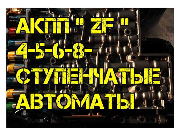
АКПП ZF: 4,5,6,8-ступенчатые автоматы
АКПП ZF: 4,5,6,8-ступенчатые автоматы
Коробки от ZF устанавливались практически на всю линейку немецкого автопрома. Это BMW, Audi, VW, Skoda, а также на ряд корейский производителей.
В данной статье мы обозначим общие неисправности 4-5-6-8-ступенчатых автоматов ZF.
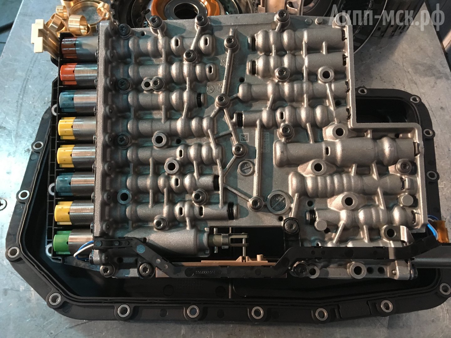
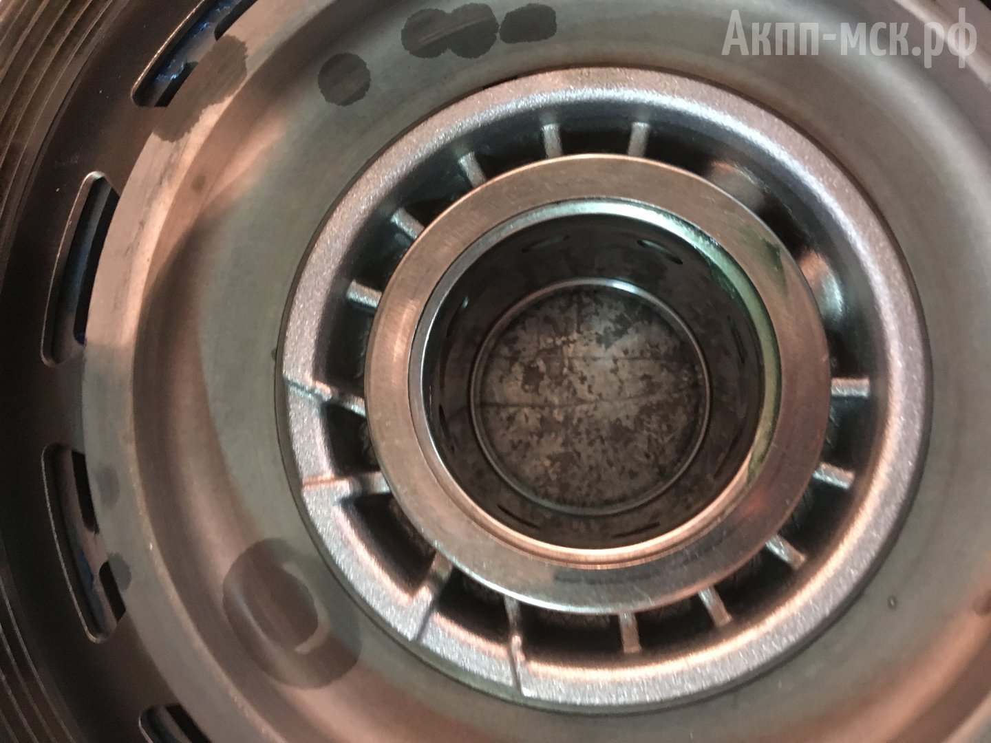
У всех этих линеек продольных трансмиссий, вплоть до 8-ступенчатых, конструкция примерно одинаковая. Главное отличие — на 4-х и 5-ступенчатых автоматах идет обычный гидроблок. На 6-ти и 8-ступенчатых автоматах уже вместо гидроблока идет мехатроник.
Основные неисправности АКПП ZF.
Ключевые неисправности 4-ступенчатых АКПП ZF – это гидроблок, насос и центральный суппорт. В результате поломок данных узлов выходят из строя фрикционы.
5-ступенчатые АКПП ZF — 5HP19, 5HP24 – имеют гидроблок как главную неисправность. В нем в обязательном порядке требуется менять основной соленоид давления черного, либо желтого цвета. Первое и более дорогое поколение – это соленоид черного цвета. Последующее поколение этого соленоида на гидроблоках 2000-2004 годов выпуска – желтого цвета.
Также подлежат замене механические клапаны в самой гидроплите. В них идут гидрокомпенсаторы на резиновой основе, которые со временем просто сдавливает и клапаны перестают держать давление.
Еще одна неисправность 5-ступок – насос. В нем на втулке установлен подшипник. Втулку проворачивает, в результате чего вытекает масло и коробка сгорает. Некоторые автосервисы по ремонту АКПП стараются просто заменить втулку на ремонтную. Поскольку посадка по втулке все равно изнашивается, наш техцентр этого не делает и ставит новый насос в сборе.
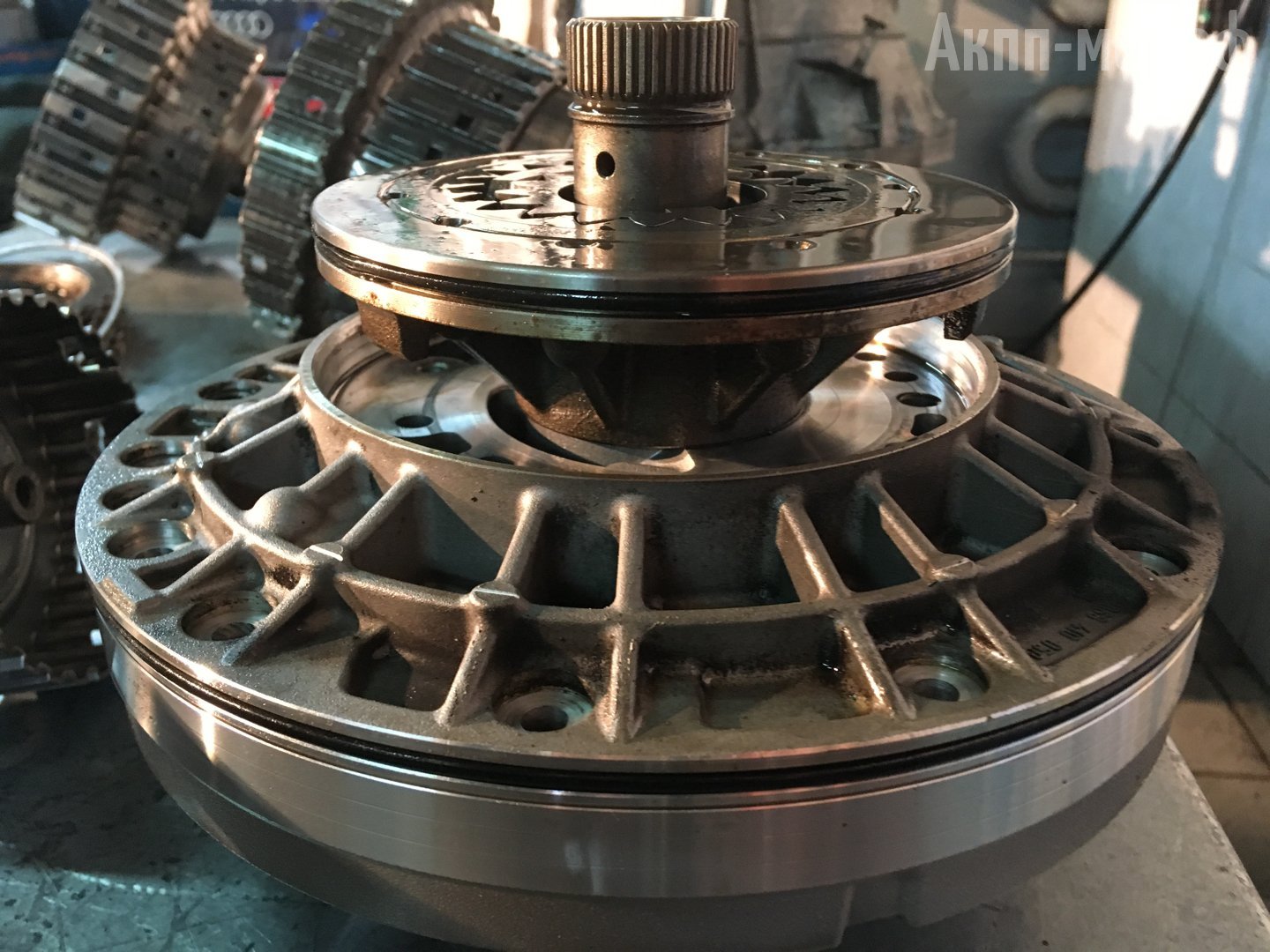
Часто на линейке ZF 5HP.. выявляются неполадки по центральному суппорту. В суппорте установлен поршень, который нередко обламывает. В результате этого на АКПП пропадают передачи. Как следствие, выходит из строя задний планетарный редуктор (для 5HP19).
Центральный суппорт ZF 6HP28
Поршень суппорта ZF 6HP28
У 5HP24 основная проблема – в гидроплите. Она идет составная из верхней и нижней пластины. Одна из этих частей лопается в результате перегрева. Давление пропадает. Решение – пластина идет под замену.
В результате неисправности насоса и гидроблока горят фрикционы. Все это выражается в следующих симптомах неисправности:
- толчки/рывки;
- пробуксовки;
- отказ в движении.
У агрегата 5HP19 частый симптом – сильные толчки/рывки при переключении селектора в положение D, или R.
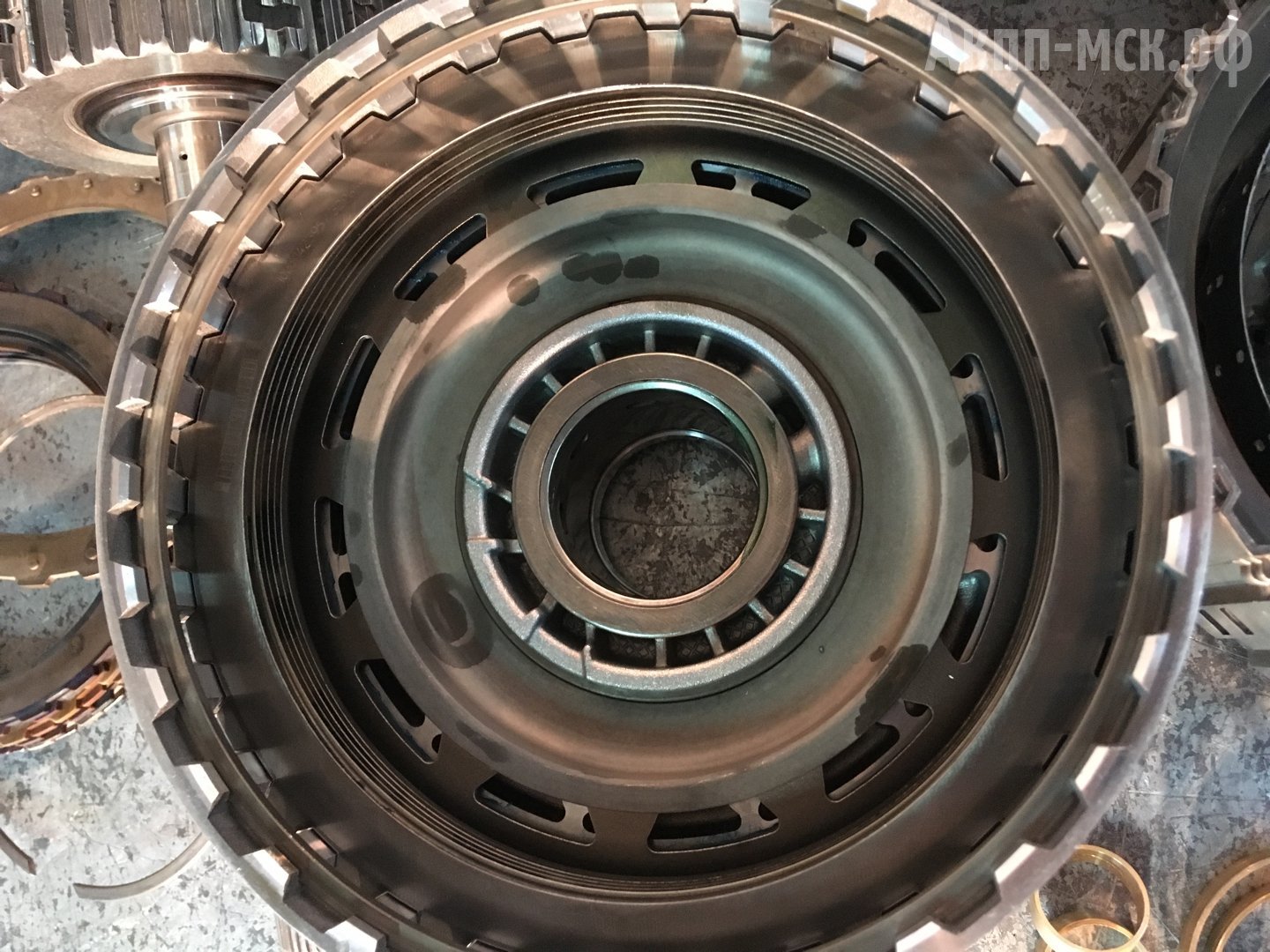
В линейке 6HP19, 6HP21, 6HP26, 6HP28, 6HP32 (Audi Q7 6.0 diesel) главная неисправность — достаточно редкий и дорогостоящий барабан Е. Его рвет по корпусу, и он начинает «давить» масло не туда, куда надо. Чаще, естественно, это случается на 6HP32. Барабан идет под замену.
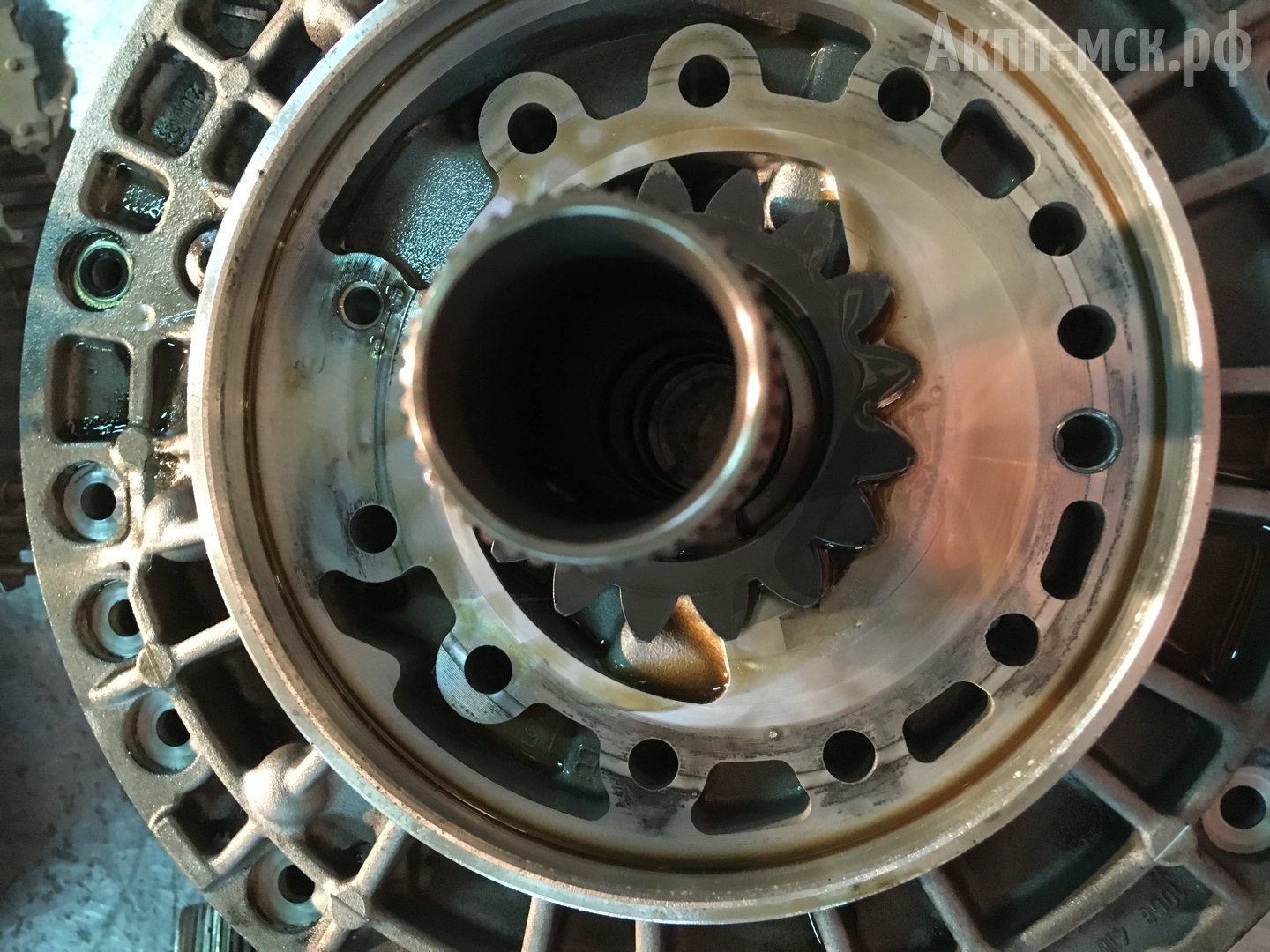
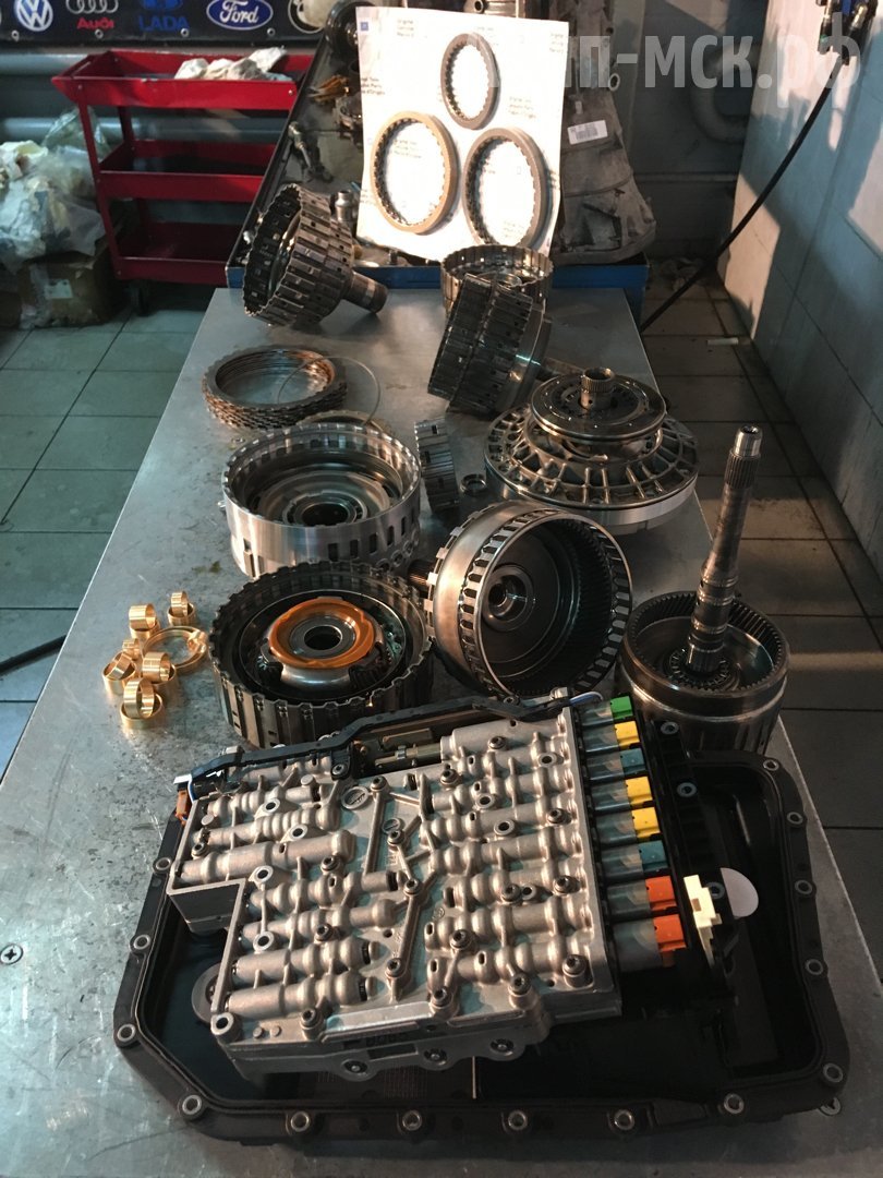
Основные неисправности линейки 6HP – мехатроник, насос и втулки. По посадкам в АКПП везде стоят наборные втулки. Когда втулка изношена, через нее уходит давление канала. Соответственно барабан перестает работать – коробка начинает буксовать, толкаться и горят фрикционы.
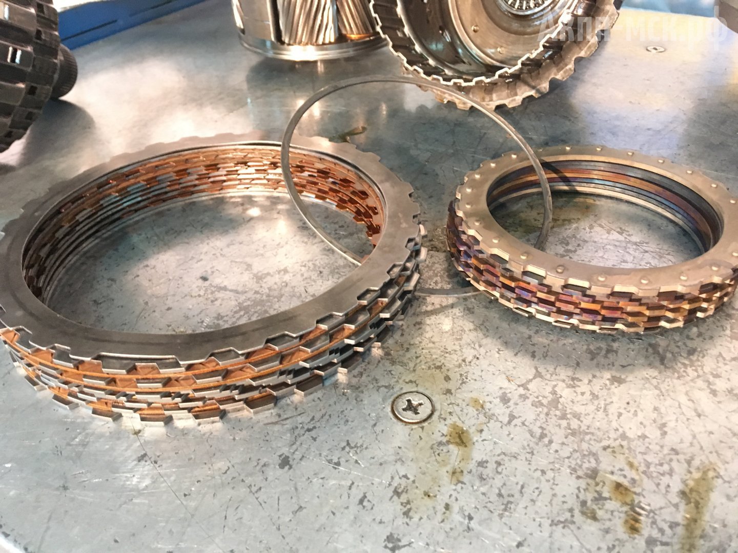
По фрикционным дискам 6-ступенчатых автоматов желательно прибегать к оригинальным комплектам. Получаем максимальное качество, по стоимости сравнимое с аналогами. По цене оригинал и неоригинал особо не отличаются.
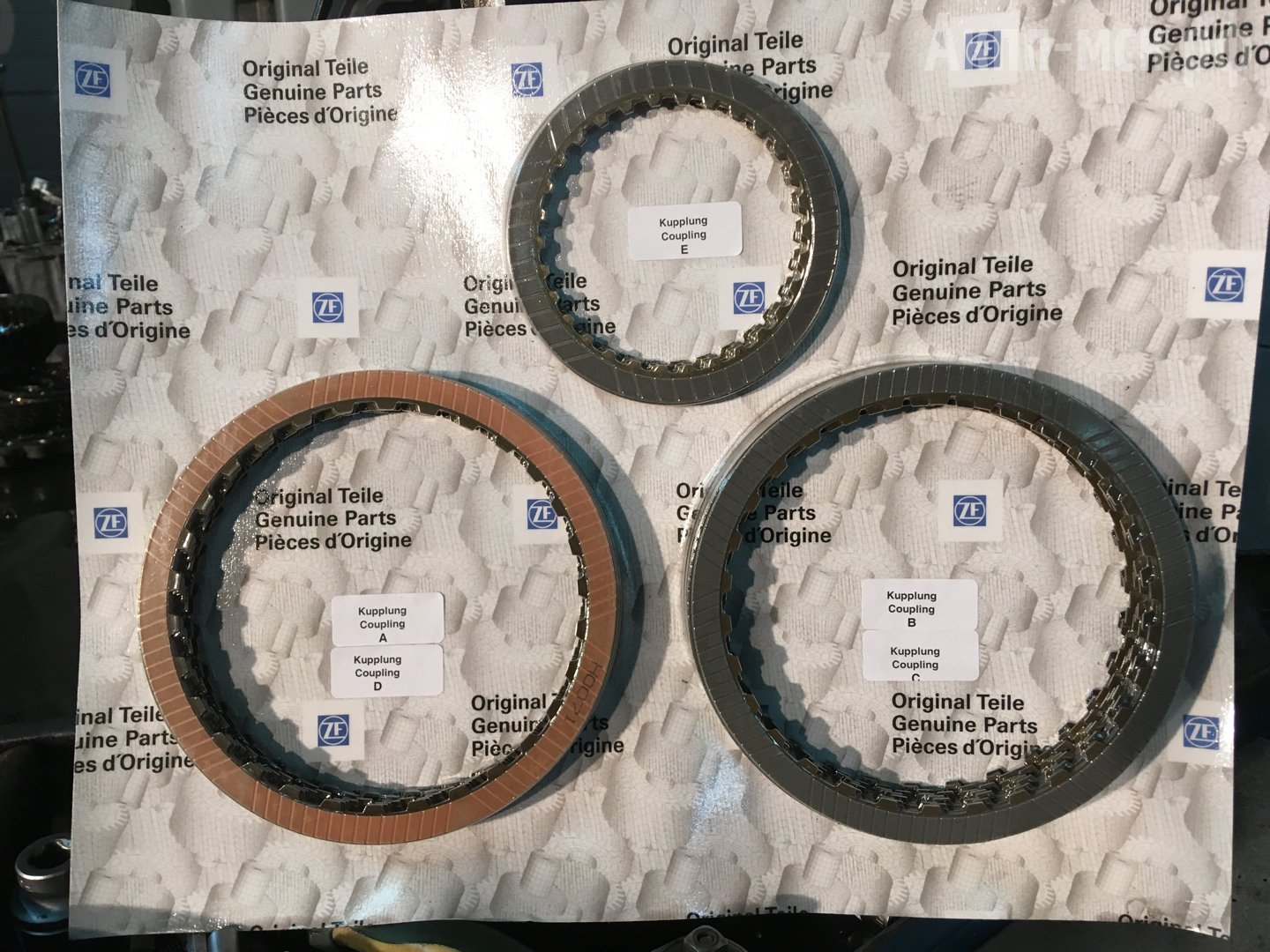
Оригинальные комплекты фрикционов ZF
По втулкам завод-изготовитель производит биметаллические втулки. Наш техцентр большее предпочтение отдает бронзовым втулкам. По опыту, они более надежные и долговечные.
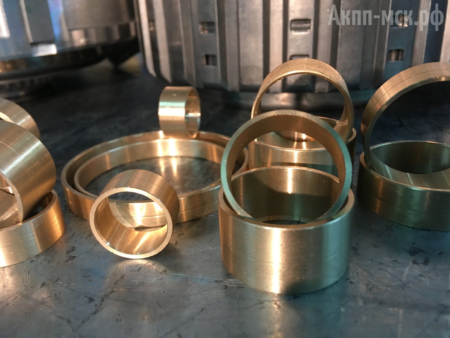
Бронзовые втулки для ремонта АКПП ZF
При ремонте обязательна замена комплекта соленоидов мехатроника. На каждой линейке 6-ти и 8-ступенчатых автоматов может быть несколько разновидностей соленоидов. Бывает 7 соленоидов; бывает 9. Также это зависит от привода ручки КПП. При наличии джойстика (например, на БМВ) имеется отдельный привод и соленоид на него и переключение происходит за счет электрики.
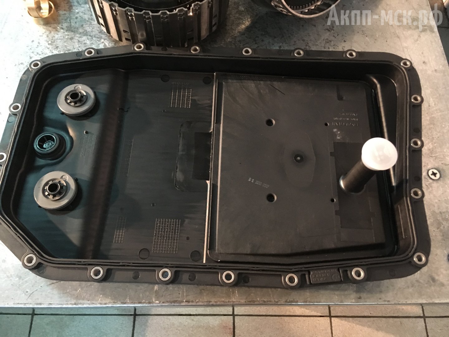
Неудобство – фильтр меняется вместе с поддоном. Поэтому фильтр ценой в 1,5-2 тысячи рублей оборачивается комплексной заменой вместе с поддоном на 7 тысяч рублей.
Частая неисправность – барабан С. В нем появляются микротрещины и он начинает пропускать масло.
По планетарным редукторам износ очень редок. Такая неисправность встречается, если автовладелец совсем запустил своевременный ремонт и эксплуатировал автомобиль до последнего.
В целом, по ремонту данные трансмиссии — неприхотливые. Особых сложностей нет. Квалифицированный сервис по ремонту АКПП сможет починить коробку за 1-4 дня. Гарантия в нашем техцентре – 1 год без ограничения по пробегу.
Агрегаты ZF – достаточно прочные. Впервые с ремонтом автовладелец может столкнуться, в среднем, не ранее 150 тыс. км. пробега. Все зависит от того, где и как эксплуатируют автомобиль, как проводят техническое обслуживание АКПП.
Диагностика АКПП ZF.
На большинство вопросов о причинах неисправности можно ответить сразу после первичной диагностики.
Первичная диагностика заключается, во-первых, в компьютерной диагностике, когда считываются параметры работы электрики и мехатроника. Если по электрике ошибок нет, проводится тест-драйв автомобиля на прогретой и непрогретой АКПП. Смотрится симптоматика коробки при работе в данных условиях.
Если трансмиссия толкается/пинается – проблема, скорее всего, в гидроблоке, либо втулках.
Если имеем полный отказ в движении – вышел из строя барабан и поэтому коробку следует снимать и дефектовать. После полного разбора уже будет точно установлен перечень вышедших из строя узлов.
Также если компьютерная диагностика ничего не выявила, берется проба масла на присутствие частиц. Если масло чистое, прозрачное и отсутствует запах гари, нужно обращать внимание лишь на мехатроник/гидроблок. Если движения нет, но масло чистое – значит срезало барабан.
То есть первичная диагностика нам покажет – стоит ли делать только мехатроник/гидроблок, или нужно полностью разбирать коробку. Это мы будем знать после диагностики на 100%. Что же произошло непосредственно с механической частью АКПП (фрикционы, барабан, втулки) станет известно после разбора. Но уже точно будет известно, что трансмиссию надо разбирать.
При наличии неисправности какая-либо буксировка запрещается. При серьезной неисправности (пробуксовки, отказ в движении, вытекло масло) в настоятельном порядке рекомендуем воспользоваться эвакуатором. При небольших рывках только на прогретой коробке, что говорит о сбоях в работе гидроблока/мехатроника, своим ходом недалеко до сервиса добраться можно.
Механика процесса следующая. Насос подключен к гидротрансформатору. Гидротрансформатор подключен к мотору. При буксировке Вы ставите автомобиль на нейтраль. Откуда Вы знаете, что в нейтрали не заклинит пакет, или планетарный механизм? Данные узлы даже в нейтралипродолжают работать. На заведенном автомобиле насос работает не в полную силу – происходит масляное голодание. Происходит перегрев гидротрансформатора и насоса. На заглушенном двигателе насос также крутится и может выходить из строя.
Поэтому любую АКПП не стоит буксировать ни в каком виде. Иначе стоимость ремонта может возрасти раза в 2, а то и больше. Лучше заплатить несколько тысяч рублей за эвакуатор.
Стоит ли покупать б/у АКПП ZF?
Подержанная коробка ZF совсем недешева. 5-ступенчатая коробка стоит в районе 50 тыс. руб., 6-ступенчатая — около 70-80 тыс. руб., 8-ступенчатая коробка может иметь ценник в 120 тыс. руб. Добавьте затраты на масло, фильтр, прошивку, снятие и установку АКПП. И гарантия будет 2 недели, либо месяц максимум. Если купленная «бэушка» не поехала – расходы на снятие/установку и масло вам никто не вернет.
Ремонт, например, 8HP70 обходится в районе стоимости подержанной коробки. Если же Вашей коробке требуется только ремонт гидроблока/мехатроника, такой ремонт с годовой гарантией обойдется гораздо дешевле любой подержанной коробки.
Важный момент. Трансмиссии, которые продает сама компания ZF – это не новые, а восстановленные трансмиссии. Новая АКПП ZF ставится только на конвейере и в рознице не представлена.
Обслуживание трансмиссий ZF.
На рынке нет коробок-автомат, предназначенных для гонок. АКПП с трущимися поверхностями – это не «механика» с прочным набором шестерен. У автоматов есть фрикционы со своим моментом и прочностью, за пределы которых они выйти не могут. Тем более у автоматической трансмиссии с пробегом больше 100 тыс. км. в любом случае имеется их износ.
- несвоевременное техническое обслуживание;
- пробки;
- нагрузки.
После ремонта АКПП прослужит как минимум не меньше, чем новая – те же 150-200 тыс. километров пробега. Прирост составит порядка 25-30%. Например, за счет использования более мощных втулок. Это не исключает необходимость проведения своевременного ТО коробки.
Под своевременным техническим обслуживанием подразумевается замена масла, профилактический осмотр и диагностика АКПП.
Регламент замены масла в АКПП ZF:
- первая замена на 60 тыс. км. пробега;
- вторая замена на 120 тыс. км. пробега;
- последующие замены каждые 35 тыс. км. пробега.
Обязательно меняйте масло. «Вечных» масел не существует. Износ идет в любом случае даже при бережной эксплуатации коробки. Те же фрикционы — трутся, осыпаются. Продукты износа попадают в фильтр. Поддон фильтра ZF удержать все это не может. Продукты износа, тем самым, попадают в гидравлическую часть трансмиссии (гидроблок/мехатроник).
Если автовладелец проехал на автомобиле 200 тысяч и решил поменять масло – это может закончится плачевными последствиями. Свежее масло обладает хорошими очищающими свойствами. Когда на изношенный фрикцион попадает свежее масло – фрикционный элемент может отслоиться от стального основания.
При больших пробегах также не рекомендуется менять масло целиком через аппарат (полная замена масла). Под давлением все продукты износа проходят через мехатроник/гидроблок. Это делается на работающем двигателе, когда все агрегаты трансмиссии работают. Клапаны гидроблока начинают клинить, забиваются и выходят из строя электромагнитные клапаны. В итоге автомобиль может даже не сойти с подъемника.
Если появились какие-либо симптомы неисправности АКПП, замена масла не поможет! Надо делать комплексную диагностику, выявлять и устранять неисправность. Зачастую, многие на замену масла просто «выбрасывают деньги на ветер» 15-20 тыс. руб., надеясь, что эта процедура поможет.
- чистый гидроблок/мехатроник;
- нормальное охлаждение.
Следите за охлаждением коробки. Многие автовладельцы выводят дополнительное охлаждение АКПП. В основном, это практикуют владельцы Range Rover. Для автомобилей, находящихся в режимах постоянного перегрева, устанавливают целых 2 больших радиатора охлаждения.
Если остались вопросы – пишите комментарии под данной статьей, либо звоните напрямую нашему мастеру. Телефон указан в разделе «Контакты». Также через любой мессенджер можно отправить мастеру фотографии запчастей, кодов ошибок и т.п., либо также позвонить и проконсультироваться по любому вопросу.
Источник
Error code list. Ergopower- EST37/A. Z F P a s s a u G m b h Donaustraße D Passau
1 Error code list Ergopower- EST37/A Z F P a s s a u G m b h Donaustraße D Passau
2 DIAGNOSE — UND PROGRAMMIERUNG EST 37 ERGOPOWER mit LAPTOP und DPA-05 Pentium Laptop min. 1,0 GHz Zulässiges Betriebssystem Windows 95 / 98 / Me oder NT Windows 2000 / Win XP Software auf CD Testman Pro und Getriebe Applikation ERGOPOWER Adapterkabel = RS = USB Programmieradapter DPA — 05 Diagnose — Set Adapterkabel ZFP Diagnose Software auf CD-ROM für ERGOPOWER EST — 37 WG 110 WG 115 EST — 37 WG 130/131 WG 160/161 EST — 37 WG 190/191 WG 210/211 EST — 37 WG 260/261 WG 310/311 Enthaltene Sprachversionen : DEUTSCH / ENGLISH / FRANCAI`S / ITALIANO Gewicht : 2,060 kg ASDT ZF Passau G.m.b.H / 11 Ducu..CorelPerspektivdarst5870AB200220017
6 codes ERGO-Control EST37A 1 Introduction 1.1 Abbreviations o.c. s.c. OP-Mode TCU EEC PTO open circuit short circuit operating mode transmission control unit electronic engine controller power take off 1.2 ZF — Display: If a fault is detected, the display shows a spanner symbol (g) for a fault. The display shows the fault code, if the gear selector is on neutral position. If more than one fault is detected, each fault code is shown for about 1 second. h f e d left character right character S T O P a b c g (special symbols a-h) 1.3 Display during operation Symbol meaning remarks 1F, 1R 2F, 2R 3F, 3R 4F 5F 6F LF, LR F or R, no gear F or R flashing actual gear and direction left digit shows actual gear right digit shows actual direction limp home gear Clutch Cutoff direction F or R selected while turbine speed is too high NN not neutral, waiting for neutral after power up or a severe fault ** oil temperature too low, no gear available *N oil temperature low, only one gear available CAUTION gear will engage if turbine speed drops to engage a gear, first move shift selector to neutral position and again to F or R position warm up engine / transmission warm up engine / transmission TE-AB N:AsttElektrikneuFc_37_V912.doc Seite 3 von 53
7 codes ERGO-Control EST37A 1 bar (special manual mode 1 st gear symbol) 2 bars manual mode 2 nd gear 3 bars manual mode 3 rd gear 4 bars manual mode 4 th gear and also 5 th and 6 th gear in 6WG 4 bars and 2 arrows automatic mode Bars flashing 6 WG: converter lockup clutch open difference of engine and turbine speed above a certain limit and lockup clutch not activated 4 WG: Downshift mode activ Spanner at least one fault activ select neutral to get fault code displayed code see faultcode list WS warning sump temperature changes between actual gear/direction while driving, in neutral only displayed if no fault is detected (spanner) WR warning retarder temperature changes between actual gear/direction while driving, in neutral only displayed if no fault is detected (spanner) WT warning torque converter temperature changes between actual gear/direction while driving, in neutral only displayed if no fault is detected (spanner) WE warning high engine speed changes between actual gear/direction while driving, in neutral only displayed if no fault is detected (spanner) PN direction F or R selected while parking brake engaged transmission in neutral until parking brake is released CAUTION: vehicle starts to move after release of parking brake EE flashing no communication with display checked wiring from TCU to display TE-AB N:AsttElektrikneuFc_37_V912.doc Seite 4 von 53
8 AEB Clutch Calibration instructions Before starting the AEB following instructions must be followed. Parking Brake must be on Gear selector lever in Neutral Transmission sump temperature between Celsius Engine Idle speed between rpm if to low increase engine speed with gas pedal and keep RPM. Correct Oil Level check Dip stick Vehicle must be on flat surfice level. Please make shure that safety instructions are followed and no persons next to the vehicle! When connecting AEB Starter symbol PL will show up on display. To start AEB please push red botton at least 3 seconds till K1 show up on display after that release the button AEB will continiue itself. Finally if clutches could be calibrated OK will show up on display! Switch off ignition, for at least 5 seconds. Any Errors appear during AEB procedure please read the Error code book German englisch copyright Hermann Wagner ASI
9 codes ERGO-Control EST37A 1.4 Display during AEB-Mode symbol meaning remarks PL AEB — Starter is plugged at the ST diagnostic plug AEB-Starter-button is pressed K1..K4,KV,KR calibrating clutch K1..K4, KV or KR resp. _ and Kx wait for start, initialization of clutch Kx, x: 1, 2, 3, 4, V, R fast fill time determination of clutch Kx and Kx = and Kx compensating pressure determination of clutch Kx OK calibration for all clutches finished Transmissions stays in neutral, you have to restart the TCU (ignition off/on) after removing AEB-Starter STOP AEB canceled (activation stopped) Transmissions stays in neutral, you have to restart the STOP and Kx AEB stopped, clutch Kx can’t be calibrated Spanner and Kx Kx couldn’t be calibrated, AEB finished E E T T FT FB engine speed too low, raise engine speed engine speed too high, lower engine speed transmission oil temperature too low, heat up transmission transmission oil temperature too high cool down transmission transmission temperature not in defined range during calibration operating mode not NORMAL or transmission temperature sensor defective or storing of Calibrated values to EEPROM-has failed. TCU (ignition off/on) Transmissions stays in neutral, you have to restart the TCU (ignition off/on) Transmissions stays in neutral, you have to restart the TCU (ignition off/on) Transmissions stays in neutral, you have to restart the TCU (ignition off/on) Transmissions stays in neutral, you have to restart the TCU (ignition off/on) FO Outputspeed_not_zero Transmissions stays in neutral, you have to restart the TCU (ignition off/on) FN Shift lever not in Neutral position Transmissions stays in neutral, you have to restart the TCU (ignition off/on) FP Parkbrake_not_applied Transmissions stays in neutral, you have to restart the STOP AEB — Starter was used incorrect or is defective. Wrong device or wrong cable used TCU (ignition off/on) Transmissions stays in neutral, you have to restart the TCU (ignition off/on) TE-AB N:AsttElektrikneuFc_37_V912.doc Seite 5 von 53
10 codes ERGO-Control EST37A 2 definition of operating modes NORMAL: There’s no failure detected in the transmission-system or the failure has no or slight effects on transmission control. TCU will work without or in special cases with little limitations. (see following table) SUBSTITUTE CLUTCH CONTROL: TCU can’t change the gears or the direction under the control of the normal clutch modulation. TCU uses the substitute strategy for clutch control. All modulations are only time controlled. (Comparable with EST 25) LIMP-HOME: The detected failure in the system has strong limitations to transmission control. TCU can engage only one gear in each direction. In some cases only one direction will be possible. TCU will shift the transmission into neutral at the first occurrence of the failure. First, the operator must shift the gear selector into neutral position. If output speed is less than a threshold for neutral to gear and the operator shifts the gear selector into forward or reverse, the TCU will select the limp-home gear. If output speed is less than a threshold for reversal speed and TCU has changed into the limp-home gear and the operator selects a shuttle shift, TCU will shift immediately into the limp-home gear of the selected direction. If output speed is greater than the threshold, TCU will shift the transmission into neutral. The operator has to slow down the vehicle and must shift the gear selector into neutral position. TRANSMISSION-SHUTDOWN: TCU has detected a severe failure that disables control of the transmission. TCU will shut off the solenoid valves for the clutches and also the common power supply (VPS1). Transmission shifts to Neutral. The park brake will operate normally, also the other functions which use ADM 1 to ADM 8. The operator has to slow down the vehicle. The transmission will stay in neutral. TCU-SHUTDOWN: TCU has detected a severe failure that disables control of system. TCU will shut off all solenoid valves and also both common power supplies (VPS1, VPS2). The park brake will engage, also all functions are disabled which use ADM 1 to ADM 8. The transmission will stay in neutral. TE-AB N:AsttElektrikneuFc_37_V912.doc Seite 6 von 53
11 3 table of fault codes LOGICAL ERROR AT GEAR RANGE SIGNAL TCU detected a wrong signal combination for the gear range cable from shift lever to TCU is broken or vehicle shift lever is defective TCU shifts transmission to neutral OP-Mode: transmission shutdown check the cables from TCU to shift lever check signal combinations of shift lever positions for gear range failure cannot be detected in systems with DW2/DW3 shift lever fault is taken back if TCU detects a valid signal for the position all LOGICAL ERROR AT DIRECTION SELECT SIGNAL TCU detected a wrong signal combination for the direction cable from shift lever to TCU is broken or vehicle shift lever is defective TCU shifts transmission to neutral OP-Mode: transmission shutdown check the cables from TCU to shift lever check signal combinations of shift lever positions F-N-R fault is taken back if TCU detects a valid signal for the direction at the shift lever all LOGICAL ERROR AT ENGINE DERATING DEVICE TCU detected of engine while derating device activ after selecting neutral, TCU changes to OP-Mode limp home check engine derating device This fault is reset after power up of TCU all LOGICAL ERROR AT PARKBRAKE STATUS Parkbrake-status-signal measured by TCU and parkbrake-status-signal send by CAN don’t fit one of the cables from status-switch to electronic box is broken one of the status-switches is defective TCU shifts transmission to DCO- State check the cables from electronic boxes to status switches check signals of the status switches Case TE-AB N:AsttElektrikneuFc_37_V912.doc Seite 7 von 53
12 LOGICAL ERROR AT DIRECTION SELECT SIGNAL 2. SHIFT LEVER TCU detected a wrong signal combination for the direction cable from shift lever 2 to TCU is broken or vehicle shift lever is defective TCU shifts transmission to neutral if selector activ OP-Mode: transmission shutdown if selector activ check the cables from TCU to shift lever 2 check signal combinations of shift lever positions F-N-R fault is taken back if TCU detects a valid neutral signal for the direction at the shift lever all case LOGICAL ERROR AT AXLE CONNECTION feedback axle connection measured by TCU and output signal axle connection don’t fit axle can t be connected or disconnected due to mechanical problem one of the cables from feedback axle connection -switch to TCU is broken check the cables from TCU to feedback axle connection switch check signals of the feedback axle connection switch all S.C. TO GROUND AT CUSTOMER SPECIFIC FUNCTION NO. 1 output pin, that looks like a s.c. to vehicle vehicle customer specific function no. 1 device has an internal defect connector pin is contacted to vehicle customer specific check the cable from TCU to customer specific function no. 1 device check the connectors from customer specific function no. 1 to TCU check the resistance of customer specific function no. 1 device 1) see chapter 4 Z- Funkti on S.C. TO BATTERY VOLTAGE AT CUSTOMER SPECIFIC FUNCTION NO. 1 customer specific check the cable from TCU to customer specific function no. 1 device check the connectors from customer 1) see chapter 4 Z- Funkti on1 TE-AB N:AsttElektrikneuFc_37_V912.doc Seite 8 von 53
13 output pin, that looks like a s.c. to battery customer specific function no. 1 device has an internal defect connector pin is contacted to battery specific function no. 1 to TCU check the resistance of customer specific function no. 1 device O.C. AT CUSTOMER SPECIFIC FUNCTION NO. 1 output pin, that looks like a o.c. for this output pin cable is defective and has no connection to TCU customer specific function no. 1 device has an internal defect connector has no connection to TCU customer specific check the cable from TCU to customer specific function no. 1 device check the connectors from customer specific function no. 1 device to TCU check the resistance of customer specific function no. 1 device 1) see chapter 4 Z- Funkti on1 1A S.C. TO GROUND AT CUSTOMER SPECIFIC FUNCTION NO. 2 output pin, that looks like a s.c. to vehicle vehicle customer specific function no. 2 device has an internal defect connector pin is contacted to vehicle customer specific check the cable from TCU to customer specific function no. 2 device check the connectors from customer specific function no. 2 device to TCU check the resistance of customer specific function no. 2 device 1) see chapter 4 Z- Funkti on2 1B S.C. TO BATTERY VOLTAGE AT CUSTOMER SPECIFIC FUNCTION NO. 2 customer specific check the cable from TCU to customer specific function no. 2 device check the connectors from customer 1) see chapter 4 Z- Funkti on2 TE-AB N:AsttElektrikneuFc_37_V912.doc Seite 9 von 53
14 output pin, that looks like a s.c. to battery customer specific function no. 2 device has an internal defect connector pin is contacted to battery specific function no. 2 device to TCU check the resistance of customer specific function no. 2 device 1C O.C. AT CUSTOMER SPECIFIC FUNCTION NO. 2 output pin, that looks like a o.c. for this output pin cable is defective and has no connection to TCU customer specific function no. 2 device has an internal defect connector has no connection to TCU customer specific check the cable from TCU to customer specific function no. 2 device check the connectors from customer specific function no. 2 device to TCU check the resistance of customer specific function no. 2 device 1) see chapter 4 Z- Funkti on2 1D S.C. TO GROUND AT CUSTOMER SPECIFIC FUNCTION NO. 3 output pin, that looks like a s.c. to vehicle vehicle customer specific function no. 3 device has an internal defect connector pin is contacted to vehicle customer specific check the cable from TCU to customer specific function no. 3 device check the connectors from customer specific function no. 3 device to TCU check the resistance of customer specific function no. 3 device 1) see chapter 4 Z- Funkti on3 1E S.C. TO BATTERY VOLTAGE AT CUSTOMER SPECIFIC FUNCTION NO. 3 customer specific check the cable from TCU to customer specific customer specific function no. 3 device 1) see chapter 4 Z- Funkti on3 TE-AB N:AsttElektrikneuFc_37_V912.doc Seite 10 von 53
15 output pin, that looks like a s.c. to battery customer specific function no. 3 device has an internal defect connector pin is contacted to battery check the connectors from customer specific function no. 3 device to TCU check the resistance of customer specific function no. 3 device 1F O.C. AT CUSTOMER SPECIFIC FUNCTION NO. 3 output pin, that looks like a o.c. for this output pin cable is defective and has no connection to TCU customer specific function no. 3 device has an internal defect connector has no connection to TCU customer specific check the cable from TCU to customer specific function no. 3 device check the connectors from customer specific function no. 3 device to TCU check the resistance of customer specific function no. 3 device 1) see chapter 4 Z- Funkti on S.C. TO BATTERY VOLTAGE AT CLUTCH CUTOFF INPUT the measured is too high: clutch cut off sensor has an internal defect connector pin is contacted to battery clutch cutoff function is disabled check the cable from TCU to the sensor check the connectors check the clutch cutoff sensor John Deere S.C. TO GROUND OR O.C. AT CLUTCH CUTOFF INPUT the measured is too low: clutch cutoff function is disabled check the cable from TCU to the sensor check the connectors check the clutch cutoff sensor John Deere TE-AB N:AsttElektrikneuFc_37_V912.doc Seite 11 von 53
16 vehicle cable has no connection to TCU clutch cut off sensor has an internal defect connector pin is contacted to vehicle or is broken S.C. TO BATTERY VOLTAGE AT LOAD SENSOR INPUT the measured is too high: load sensor has an internal defect connector pin is contacted to battery retarder function is affected TCU uses default load check the cable from TCU to the sensor check the connectors check the load sensor sensor check the assembly tolerances of load sensor availability of retarder depends on default load ohne CAN S.C. TO GROUND OR O.C. AT LOAD SENSOR INPUT the measured is too low: vehicle cable has no connection to TCU load sensor has an internal defect connector pin is contacted to vehicle or is broken retarder function is affected TCU uses default load check the cable from TCU to the sensor check the connectors check the load sensor sensor check the assembly tolerances of load sensor availability of retarder depends on default load ohne CAN S.C. TO BATTERY VOLTAGE OR O.C. AT TRANSMISSION SUMP TEMPERATURE SENSOR INPUT the measured is too high: cable has no connection to TCU temperature sensor has an internal defect, TCU uses default temperature check the cable from TCU to the sensor check the connectors check the temperature sensor TE-AB N:AsttElektrikneuFc_37_V912.doc Seite 12 von 53
17 connector pin is contacted to battery or is broken S.C. TO GROUND AT TRANSMISSION SUMP TEMPERATURE SENSOR INPUT the measured is too low: vehicle temperature sensor has an internal defect connector pin is contacted to vehicle, TCU uses default temperature check the cable from TCU to the sensor check the connectors check the temperature sensor S.C. TO BATTERY VOLTAGE OR O.C. AT RETARDER TEMPERATURE SENSOR INPUT the measured is too high: cable has no connection to TCU temperature sensor has an internal defect connector pin is contacted to battery or is broken, TCU uses default temperature check the cable from TCU to the sensor check the connectors check the temperature sensor 6WG S.C. TO GROUND AT RETARDER TEMPERATURE SENSOR INPUT the measured is too low: vehicle temperature sensor has an internal defect connector pin is contacted to vehicle, TCU uses default temperature check the cable from TCU to the sensor check the connectors check the temperature sensor 6WG TE-AB N:AsttElektrikneuFc_37_V912.doc Seite 13 von 53
18 S.C. TO BATTERY VOLTAGE OR O.C. AT PARKING BRAKE SENSOR INPUT the measured is too high: cable has no connection to TCU sensor has an internal defect connector pin is contacted to battery or is broken TCU uses default value check the cable from TCU to the sensor check the connectors check the parking brake sensor all 2A S.C. TO GROUND PARKING BRAKE SENSOR INPUT the measured is too low: vehicle sensor has an internal defect connector pin is contacted to vehicle TCU uses default value check the cable from TCU to the sensor check the connectors check the parking brake sensor all 2B INCHSENSOR-SIGNAL MISMATCH the measured from CCO and CCO2 signal don t match: cable is defective sensor has an internal defect During inching mode: TCU shifts to neutral While not inching: no change check the cable from TCU to the sensor check the connectors check sensor all S.C. TO BATTERY VOLTAGE OR O.C. AT ENGINE SPEED INPUT TCU measures a higher than 7.00 V at speed input pin cable has no connection to TCU speed sensor has an internal defect OP-Mode: substitute clutch control check the cable from TCU to the sensor check the connectors check the speed sensor TE-AB N:AsttElektrikneuFc_37_V912.doc Seite 14 von 53
19 connector pin is contacted to battery or has no contact S.C. TO GROUND AT ENGINE SPEED INPUT TCU measures a less than 0.45V at speed input pin cable / connector is defective and is contacted to vehicle speed sensor has an internal defect OP-Mode: substitute clutch control check the cable from TCU to the sensor check the connectors check the speed sensor LOGICAL ERROR AT ENGINE SPEED INPUT TCU measures a engine speed over a threshold and the next moment the measured speed is zero cable / connector is defective and has bad contact speed sensor has an internal defect sensor gap has the wrong size OP-Mode: substitute clutch control check the cable from TCU to the sensor check the connectors check the speed sensor check the sensor gap This fault is reset after power up of TCU S.C. TO BATTERY VOLTAGE OR O.C. AT TURBINE SPEED INPUT TCU measures a higher than 7.00 V at speed input pin cable has no connection to TCU speed sensor has an internal defect connector pin is contacted to battery or has no contact OP-Mode: substitute clutch control if a failure is existing at output speed, check the cable from TCU to the sensor check the connectors check the speed sensor S.C. TO GROUND AT TURBINE SPEED INPUT TCU measures a less than 0.45V at speed input pin OP-Mode: substitute clutch control if a failure is existing at output speed, check the cable from TCU to the sensor check the connectors check the speed sensor TE-AB N:AsttElektrikneuFc_37_V912.doc Seite 15 von 53
20 cable / connector is defective and is contacted to vehicle speed sensor has an internal defect LOGICAL ERROR AT TURBINE SPEED INPUT TCU measures a turbine speed over a threshold and at the next moment the measured speed is zero cable / connector is defective and has bad contact speed sensor has an internal defect sensor gap has the wrong size OP-Mode: substitute clutch control if a failure is existing at output speed, check the cable from TCU to the sensor check the connectors check the speed sensor check the sensor gap This fault is reset after power up of TCU S.C. TO BATTERY VOLTAGE OR O.C. AT INTERNAL SPEED INPUT TCU measures a higher than 7.00 V at speed input pin cable has no connection to TCU speed sensor has an internal defect connector pin is contacted to battery or has no contact OP-Mode: substitute clutch control check the cable from TCU to the sensor check the connectors check the speed sensor S.C. TO GROUND AT INTERNAL SPEED INPUT TCU measures a less than 0.45V at speed input pin cable / connector is defective and is contacted to vehicle speed sensor has an internal defect OP-Mode: substitute clutch control check the cable from TCU to the sensor check the connectors check the speed sensor LOGICAL ERROR AT INTERNAL SPEED INPUT OP-Mode: substitute clutch control check the cable from TCU to the sensor check the connectors This fault is reset after power up of TCU TE-AB N:AsttElektrikneuFc_37_V912.doc Seite 16 von 53
21 TCU measures a internal speed over a threshold and at the next moment the measured speed is zero cable / connector is defective and has bad contact speed sensor has an internal defect sensor gap has the wrong size check the speed sensor check the sensor gap 3A S.C. TO BATTERY VOLTAGE OR O.C. AT OUTPUT SPEED INPUT TCU measures a higher than 12.5 V at speed input pin cable has no connection to TCU speed sensor has an internal defect connector pin is contacted to battery or has no contact special mode for gear selection OP-Mode: substitute clutch control if a failure is existing at turbine speed, check the cable from TCU to the sensor check the connectors check the speed sensor 3B S.C. TO GROUND AT OUTPUT SPEED INPUT TCU measures a less than 1.00V at speed input pin cable / connector is defective and is contacted to vehicle speed sensor has an internal defect special mode for gear selection OP-Mode: substitute clutch control if a failure is existing at turbine speed, check the cable from TCU to the sensor check the connectors check the speed sensor 3C LOGICAL ERROR AT OUTPUT SPEED INPUT TCU measures a output speed over a threshold and at the next moment the measured speed is zero cable / connector is defective and has bad contact speed sensor has an internal defect special mode for gear selection OP-Mode: substitute clutch control if a failure is existing at turbine speed, check the cable from TCU to the sensor check the connectors check the speed sensor check the sensor gap This fault is reset after power up of TCU TE-AB N:AsttElektrikneuFc_37_V912.doc Seite 17 von 53
22 sensor gap has the wrong size 3D 71 TURBINE SPEED ZERO DOESN T FIT TO OTHER SPEED SIGNALS — — not used 3E OUTPUT SPEED ZERO DOESN T FIT TO OTHER SPEED SIGNALS if transmission is not neutral and the shifting has finished, TCU measures outputspeed zero and turbine speed or internal speed not equal to zero. speed sensor has an internal defect sensor gap has the wrong size special mode for gear selection OP-Mode: substitute clutch control if a failure is existing at turbine speed, check the sensor signal of output speed sensor check the sensor gap of output speed sensor check the cable from TCU to the sensor This fault is reset after power up of TCU GEAR RANGE RESTRICTION SIGNAL CAN signal for gear range restriction is defective cluster controller is defective no gear range restriction check cluster controller check cable to cluster controller Case FCAN MESSAGE GEAR RANGE SELECT (ZF_3_IDENT) contains invalid data DECLUTCH MODULATION SELECTION SIGNAL gear range set from 1 st to 5 th check FWD controller O&K — — not used Case TCU RECEIVES MESSAGES GEAR RANGE SELECT (ZF_3_IDENT) AND FRONT WHEEL DRIVE STATUS (V_IDENT_FWD) ALTHOUGH CONFIGURATION STATES THAT FWD CONTROLLER IS NOT INSTALLED FMR1 TIMEOUT Timeout of CAN-message FMR1 from ignore FWD commands reconfigure with TCU Configuration Command (ID PC) TCU operates like jake brake is off and exhaut brake is off. check engine controller O&K IES TE-AB N:AsttElektrikneuFc_37_V912.doc Seite 18 von 53
23 engine controller CAN wire/connector is broken CAN wire/connector is defective and has contact to vehicle or engine controller is defective check cable to engine controller FMR2 TIMEOUT Timeout of CAN-message FMR2 from engine controller CAN wire/connector is broken CAN wire/connector is defective and has contact to vehicle or engine controller is defective OP-Mode: substitute clutch control check engine controller check cable to engine controller IES EAMODUL1 TIMEOUT Timeout of CAN-message EAM1 from I/O — controller CAN wire/connector is broken CAN wire/connector is defective and has contact to vehicle or and uses substitute gear selector check I/O controller check cable to I/O controller Liebh err ABS TIMEOUT Timeout of CAN-message ABS from ABS — controller CAN wire/connector is broken CAN wire/connector is defective and has contact to vehicle or check ABS controller check cable to ABS controller IES TE-AB N:AsttElektrikneuFc_37_V912.doc Seite 19 von 53
24 MDU1 TIMEOUT Timeout of CAN-message MDU1 from cluster controller CAN wire/connector is broken CAN wire/connector is defective and has contact to vehicle or TCU keeps old auto downshift information and old manual downshift information check cluster controller check cable to cluster controller John Deere DCT1 TIMEOUT Timeout of CAN-message DCT1 from display computer CAN wire/connector is broken CAN wire/connector is defective and has contact to vehicle or check display computer check cable to display computer JCB, Kalma r GEAR RANGE SELECT TIMEOUT Timeout of CAN-message Gear Range Select (ZF_3_IDENT) CAN wire/connector is broken CAN wire/connector is defective and has contact to vehicle or FWD Controller is defective gear range set from 1 st to 5 th check FWD controller O&K DNS1 TIMEOUT Timeout of CAN-message DNS1 from OMRON-master CAN wire/connector is broken check OMRON-master check cable to OMRON-master TE-AB N:AsttElektrikneuFc_37_V912.doc Seite 20 von 53
25 CAN wire/connector is defective and has contact to vehicle or SCT1 TIMEOUT Timeout of CAN-message SCT 1 from steering computer CAN wire/connector is broken CAN wire/connector is defective and has contact to vehicle or check steering computer check cable to steering computer Kalma r FLC1 TIMEOUT Timeout of CAN-message FCL1 from cluster controller CAN wire/connector is broken CAN wire/connector is defective and has contact to vehicle or TCU keeps old auto/man selection, old Clutch cutoff selection and old Clutch Cuttoff Setting check cluster controller check cable to cluster controller John Deere FRONT WHEEL DRIVE STATUS TIMEOUT Timeout of CAN-message Front Wheel Drive Status (V_IDENT_FWD) CAN wire/connector is broken CAN wire/connector is defective and has contact to vehicle or FWD Controller is defective check FWD controller O&K ENGINE CONF TIMEOUT Timeout of CAN-message ENGINE CONF OP-Mode: substitute clutch control check engine controller J1939 TE-AB N:AsttElektrikneuFc_37_V912.doc Seite 21 von 53
26 from engine controller CAN wire/connector is broken CAN wire/connector is defective and has contact to vehicle or check cable to engine controller EEC1 TIMEOUT Timeout of CAN-message EEC1 from EEC controller CAN wire/connector is broken CAN wire/connector is defective and has contact to vehicle or OP-Mode: substitute clutch control check EEC controller check cable to EEC controller J EEC3 TIMEOUT Timeout of CAN-message EEC3 from EEC controller CAN wire/connector is broken CAN wire/connector is defective an has contact to vehicle or OP-Mode: substitute clutch control check EEC controller check cable to EEC controller J TEST MODE SIGNAL CAN signal for test mode status is defective cluster controller is defective Testmode is aborted, if activ check cluster controller check cable to cluster controller Case 5A PARKBRAKE STATUS SIGNAL CAN signal for parkbrake status is defective cluster controller is defective. check cluster controller check cable to cluster controller Case, TE-AB N:AsttElektrikneuFc_37_V912.doc Seite 22 von 53
27 5B SHIFT QUALITY SEL SIGNAL CAN signal for shift qualtiy selection is defective cluster controller is defective check cluster controller check cable to cluster controller Not used Case 5C AUTO DOWNSHIFT SIGNAL CAN signal for automatic downshift is defective cluster controller is defective last selection is kept check cluster controller check cable to cluster controller John Deere 5D MANUAL DOWNSHIFT SIGNAL CAN signal for manual downshift is defective cluster controller is defective last selection is kept check cluster controller check cable to. controller John Deere 5E CCO REQUEST SIGNAL CAN signal for CCO request is defective cluster controller is defective last selection is kept check cluster controller check cable to. controller John Deere 5F SHIFT LEVER SIGNAL CAN signal for shift lever is defective I/O controller is defective and uses informations from substitute shift lever check I/O controller check cable to I/O controller Liebh err, 5F TRANSMISSION NEUTRAL REQUEST SIGNAL CAN signal for transmission Neutral Request is defective check steering computer check cable to steering computer Kalma r TE-AB N:AsttElektrikneuFc_37_V912.doc Seite 23 von 53
28 steering computer is defective 5F CAN MESSAGE FRONT WHEEL DRIVE STATUS (V_IDENT_FWD) CONTAINS INVALID DATA ADDITIONAL BRAKE STATUS SIGNAL CAN signal for additional park brake status is defective I/O controller is defective check FWD controller O&K check I/O controller check cable to I/O controller Liebh err AEB REQUEST SIGNAL CAN signal for AEB request is defective I/O controller is defective PTO TORQUE SIGNAL CAN signal for PTO torque is defective I/O controller is defective Last selection is kept, TCU uses default PTO torque signal check I/O controller check cable to I/O controller check I/O controller check cable to I/O controller Liebh err,, John Deere Liebh err DRIVING MODE SIGNAL CAN signal for driving mode is defective I/O controller is defective, TCU uses default driving mode signal check I/O controller check cable to I/O controller Liebh err STARTING GEAR SIGNAL CAN signal for starting gear is defective I/O controller is defective (illegal starting gear), TCU uses default starting gear check I/O controller check cable to I/O controller Liebh err ENGINGE TORQUE SIGNAL OP-Mode:substitute clutch check engine controller IES, TE-AB N:AsttElektrikneuFc_37_V912.doc Seite 24 von 53
Источник
Пояснения к таблице
- Коды неисправностей могут быть считаны в двух стандартах, в ВАГовском формате, без буквы Р впереди и в OBD-формате, с буквой Р вначале. Правильнее конечно первый вариант, при показе кодов неисправностей в OBD-формате ( обычно мультимарочными сканерами) могут возникать ошибки в интерпретации. В любом случае определенному коду в ВАГ-формате соответствует определенный код в OBD-формате. Оба приведены в таблице.
- У блоков управления примерно с 2007 года коды неисправностей могут быть в другом обозначении, но интерпретация (название ошибки) будет прежним, найти ошибку в таблице будет легко
- Графа “Устранение неисправности” чаще имеет справочный характер — это то, как производитель предлагал бороться с проблемой. Обычно не стоит этому следовать.
- После каждой ошибки приведен мой комментарий что за ошибка и как её устранить
- Внизу добавил две актуальные ошибки, которых не было в таблице
|
Вывод данных на -VAS 5051 A- |
Возможная причина неисправности |
Устранение неисправности |
||||
|
16889 / P0505 |
|
|
Встречается на старых коробках, проблемы с мотором, к АКПП не относится
|
Вывод данных на -VAS 5051 A- |
Возможная причина неисправности |
Устранение неисправности |
||
|
16987 / P0603 |
|
Внутренняя ошибка блока. Можно попытаться залить новую прошивку, но обычно блок под замену
|
Вывод данных на -VAS 5051 A- |
Возможная причина неисправности |
Устранение неисправности |
||
|
16988 / P0604 |
|
Внутренняя ошибка блока. Можно попытаться залить новую прошивку, но 90 процентов, что блок под замену
|
Вывод данных на -VAS 5051 A- |
Возможная причина неисправности |
Устранение неисправности |
||
|
16989 / P0605 |
|
Внутренняя ошибка блока. Можно попытаться залить новую прошивку, но 90 процентов, что блок под замену
|
Вывод данных на -VAS 5051 A- |
Возможная причина неисправности |
Устранение неисправности |
||
|
17086 / P0702 |
|
Внутренняя ошибка блока. Можно попытаться залить новую прошивку, но 90 процентов, что блок под замену
|
Вывод данных на -VAS 5051 A- |
Возможная причина неисправности |
Устранение неисправности |
||||
|
17087 / P0703 |
|
|
||||
|
|
|||||
|
|
t |
Сигнал от выключателя стоп-сигнала -F- передается с блока управления двигателя на блок управления АКПП -J217-. |
|
t |
Обмен данными между блоками управления производится через CAN-шину → Глава. |
|
t |
После десяти последовательных появлений несоответствия между выключателями стоп-сигнала -F- (один выключатель срабатывает, другой нет) данная ошибка сохраняется в блоке управления коробки передач. К ЭБУ не относится.Обычно замена “лягушки” тормоза |
|
Вывод данных на -VAS 5051 A- |
Возможная причина неисправности |
Устранение неисправности |
||
|
17090 / P0706 |
|
|||
|
||||
|
||||
|
|
t |
Электрическое обозначение датчика диапазона измерения передаточного отношения мультифункциональный переключатель -F125-. |
|
t |
Магнит вала переключения передает на датчики Холла мультифункционального переключателя -F125- фактическое положение вала переключателя. При правильной установке рычага управления КП эта позиция соответствует положению селектора АКПП. |
|
t |
Мультифункциональный переключатель -F125- интегрирован в блок управления АКПП -J217-. |
|
Неисправен ЭБУ АКПП, требуется (всегда возможен) ремонт ЭБУ |
|
Вывод данных на -VAS 5051 A- |
Возможная причина неисправности |
Устранение неисправности |
||
|
17094 / P0710 |
|
|
t |
Датчик температуры масла КП -G93- интегрирован в блок управления АКПП -J217-. |
|
Обычно ремонт блока НЕ возможен, замена |
|
Вывод данных на -VAS 5051 A- |
Возможная причина неисправности |
Устранение неисправности |
||
|
17095 / P0711 |
|
|
t |
Датчик температуры масла КП -G93- интегрирован в блок управления АКПП -J217-. |
|
Обычно ремонт блока не возможен, замена |
|
Вывод данных на -VAS 5051 A- |
Возможная причина неисправности |
Устранение неисправности |
||
|
17096 / P0712 |
|
|
t |
Датчик температуры масла КП -G93- интегрирован в блок управления АКПП -J217-. |
|
t |
Условие для распознавания ошибки: измеряемый уровень температуры опустился ниже –40 °C. |
|
Обычно ремонт блока не возможен, замена |
|
Вывод данных на -VAS 5051 A- |
Возможная причина неисправности |
Устранение неисправности |
||
|
17097 / P0713 |
|
|||
|
|
t |
Датчик температуры масла КП -G93- интегрирован в блок управления АКПП -J217-. |
|
t |
Условие для распознавания ошибки: измеряемый уровень температуры превысил 150 °C. |
|
Обычно ремонт блока не возможен, замена |
|
Вывод данных на -VAS 5051 A- |
Возможная причина неисправности |
Устранение неисправности |
||
|
17100 / P0716 |
|
|
t |
Датчик числа оборотов на входе КП -G182- интегрирован в блок управления Getriebe -J217- integriert. |
|
t |
Условие для распознавания ошибки: блок управления АКПП -J217- временно распознает число оборотов входного вала более 7000об/мин. (бензиновые двигатели) либо более 5500об/мин. (двигатели TDI). |
Неисправен ЭБУ, либо (ЧАЩЕ) эта ошибка будет появляться вторично при ошибке 17105 по датчику скорости выходного вала G195 . В любом случае ремонт ЭБУ
|
Вывод данных на -VAS 5051 A- |
Возможная причина неисправности |
Устранение неисправности |
||
|
17101 / P0717 |
|
|||
|
|
t |
Датчик числа оборотов на входе КП -G182- интегрирован в блок управления АКПП -J217-. |
|
t |
Условие для распознавания ошибки: блок управления коробки передач временно распознает число оборотов входного вала менее или равное 1об/мин. и одновременно число оборотов входного вала более 100об/мин. Неисправен ЭБУ, либо (ЧАЩЕ) эта ошибка будет появляться вторично при ошибке 17105 по датчику скорости выходного вала G195 . В любом случае ремонт ЭБУ |
|
Вывод данных на -VAS 5051 A- |
Возможная причина неисправности |
Устранение неисправности |
||
|
17105 / P0721 |
|
|
t |
Датчик числа оборотов на выходе КП -G195- интегрирован в блок управления АКПП -J217-. Неисправен ЭБУ. Ремонт возможен. Обычно сопровождается второй ошибкой- 17101 |
|
Вывод данных на -VAS 5051 A- |
Возможная причина неисправности |
Устранение неисправности |
||
|
17106 / P0722 |
|
|||
|
|
t |
Датчик числа оборотов на выходе КП -G195- интегрирован в блок управления АКПП -J217-. |
Неисправен ЭБУ. Ремонт возможен. Обычно сопровождается второй ошибкой- 17101
Ошибка 17110 / P0726
|
Вывод данных на -VAS 5051 A- |
Возможная причина неисправности |
Устранение неисправности |
||||||||
|
17110 / P0726 |
|
|
||||||||
|
|
|||||||||
|
|
|||||||||
|
||||||||||
|
|
Вывод данных на -VAS 5051 A- |
Возможная причина неисправности |
Устранение неисправности |
||||||
|
17111 / P0727 |
|
|
||||||
|
|
|||||||
|
||||||||
|
|
t |
При прерывании передачи числа оборотов запасной сигнал числа оборотов двигателя передается от блока управления двигателя по CAN-шине на блок управления АКПП -J217-. |
В первую очередь проверить, нет ли проблем с датчиком коленвала на моторе и видит ли ЭБУ МОТОРА обороты двигателя . Если видит, но в измеряемых группах по АКПП значение не отображается, то неисправен ЭБУ. Ремонт возможен
Ошибка 17114 / P0730
|
Вывод данных на -VAS 5051 A- |
Возможная причина неисправности |
Устранение неисправности |
||
|
17114 / P0730 |
||||
|
|
ВАЖНО! Если это единственная ошибка, то вероятнее действительно механические проблемы в АКПП. НО! Если эта ошибка присутствует ОДНОВРЕМЕННО с ЕЩЕ ДВУМЯ- 17105 и 17101( по датчикам G195 И G182), но она является вторичной, рассчетной и пропадет при устранении первых двух ошибок. Это частая ситуация! |
|
Вывод данных на -VAS 5051 A- |
Возможная причина неисправности |
Устранение неисправности |
||||||
|
17134 / P0750 |
|
|
||||||
|
Вывод данных на -VAS 5051 A- |
Возможная причина неисправности |
Устранение неисправности |
||||||
|
17137 / P0753 |
|
|
|
t |
Провода интегрированы в блок управления АКПП -J217- и могут быть заменены только вместе с блоком управления коробки передач. |
ВАЖНО! Если присутствует ТОЛЬКО ошибка 17134, то это функциональный сбой ГИДРОБЛОКА, Эбу не причем. Требуется замена гидроблока( сам клапан N88 также не причем!). НО если присутствуют обе ошибки 17134 и 17137 одновременно, То проблема только в ЭБУ. Чаще ремонт возможен
Ошибка 18031 / P1623
|
Вывод данных на -VAS 5051 A- |
Возможная причина неисправности |
Устранение неисправности |
||||
|
18031 / P1623 |
|
|
||||
|
|
|||||
|
||||||
|
||||||
|
|
t |
Шина данных также называется CAN-шиной. |
|
t |
Обмен данными между блоками управления производится через CAN-шину → Глава. |
|
t |
Хотя блок управления и может отправлять сигналыи данные, но он ничего не может принимать. |
Довольно запутанная ситуация при ошибке “нет связи по КАН-шине” Вкратце.Более новые, примерно с 2007 года блоки имеют диагностику по CAN-шине, и если вы видите эту ошибку в ТАКОМ Эбу, это значит чио проблема с Кан- внешняя, проводка или другой блок, иначе бы вы в этот блок не вошли диагностикой. Для более старых блоков, с диагностикой по К-линии, проблема может быть с КАН-интерфейсом ЭБУ АКПП. Проверяется опросом других блоков- моторника, АБС, приборки. В блоках измерений 125й канал. Если связь с ЭБУ АКПП стоит как “0”, то проблема в ЭБУ АКПП, если “1”, надо искать другую причину
Ошибка 18112 / P0704
|
Вывод данных на -VAS 5051 A- |
Возможная причина неисправности |
Устранение неисправности |
||||||
|
18112 / P1704 |
|
|
||||||
|
|
|||||||
|
||||||||
|
|
|
t |
Не является самостоятельной деталью. |
|
t |
У автомобилей с двигателями TDI в блоке с датчиком положения педали акселераора -G79- |
|
t |
У автомобилей с бензиновым двигателем функцию берут на себя датчик положения педали акселератора -G79- и датчик 2 положения педали акселератора -G185-, оба интегрированы в модуль педали акселератора |
|
t |
Сигнал от датчика положения педали акселератора -G79- или модуля педали акселератора передается с блока управления двигателя на блок управления АКПП -J217-. |
|
t |
Обмен данными между блоками управления производится через CAN-шину → Глава. |
|
Такая ошибка не встречается |
|
Вывод данных на -VAS 5051 A- |
Возможная причина неисправности |
Устранение неисправности |
||||
|
18113 / P1705 |
|
|
||||
|
||||||
|
|
Механические проблемы в АКПП |
|
Вывод данных на -VAS 5051 A- |
Возможная причина неисправности |
Устранение неисправности |
||||
|
18132 / P1724 |
|
|||||
|
|
|
t |
Блок управления не может определить обрыв цепи. |
Ошибка означает, что в исполнительной цепи блокировки стартера есть какой-то обрыв, обычно дополнительный иммобилайзер.Эбу и коробка не причем, ничего делать не надо
Ошибка 18137 / P1729
|
Вывод данных на -VAS 5051 A- |
Возможная причина неисправности |
Устранение неисправности |
||||
|
18137 / P1729 |
|
|||||
|
|
|
t |
Блок управления не может определить обрыв цепи. |
Ошибка означает, что в исполнительной цепи блокировки стартера есть какой-то обрыв, обычно дополнительный иммобилайзер.Эбу и коробка не причем, ничего делать не надо
Ошибка 18141 / P1723
|
Вывод данных на -VAS 5051 A- |
Возможная причина неисправности |
Устранение неисправности |
||||||||
|
18141 / P1733 |
|
|
||||||||
|
|
t |
В случае этой ошибки блок измерительных величин 003 всегда показывает „выключатель понижения передачи“. |
В подавляющем большинстве случаев ошибки по переключателю типтроника F189 (не путать с F125 !) не связаны с ЭБУ АКПП. Эта деталь (F189) находится в салоне, под накладкой селектора. Могут быть сломана, (чаще залита) плата F189 либо сами шторки, на которых стоят магниты. Необходима замена этих деталей. ЭБУ не причем.Наличие этой ошибки никак не влияет на работу АКПП
Ошибка 18147 / P1739
|
Вывод данных на -VAS 5051 A- |
Возможная причина неисправности |
Устранение неисправности |
||||||||
|
18147 / P1739 |
|
|
||||||||
|
|
t |
Появится сообщение об ошибке, если помимо положения селектора АКПП „D“ было распознано срабатывание переключателя повышения передач. |
|
t |
В случае этой ошибки блок измерительных величин 003 всегда показывает „выключатель повышения передачи“. |
В подавляющем большинстве случаев ошибки по переключателю типтроника F189 (не путать с F125 !) не связаны с ЭБУ АКПП. Эта деталь (F189) находится в салоне, под накладкой селектора. Могут быть сломана, (чаще залита) плата F189 либо сами шторки, на которых стоят магниты. Необходима замена этих деталей. ЭБУ не причем.Наличие этой ошибки никак не влияет на работу АКПП
Ошибка 18148 / P1740
|
Вывод данных на -VAS 5051 A- |
Возможная причина неисправности |
Устранение неисправности |
||
|
18148 / P1740 |
|
|||
|
|
t |
Сообщение об ошибке появится, если температура сцепления слишком высокая. |
|
t |
Вращающий момент двигателя автоматически снижается до тех пор, пока температура вновь не опустится до допустимого рабочего уровня. |
Обычно возникает при избыточном трении, сильной пробуксовке сцепления. Причина в несправном гидроблоке, ЭБУ не причем
Ошибка 18149 / P1741
|
Вывод данных на -VAS 5051 A- |
Возможная причина неисправности |
Устранение неисправности |
||
|
18149 / P1741 |
|
|
t |
Если данная ошибка возникает спорадически, очистить память неисправностей. Затем совершить пробную поездку и заново опросить память неисправностей. Если ошибка возникает снова, заменить гидравлический блок управления. |
Самая частая ошибка при неисправном гидроблоке, почти всегда “старого образца”, до 2005 года. Обычно сопровождается рывками при старте и ошибкой по датчику давления G193. Не лечится, только замена гидроблока. Иногда может пройти само после пары дней езды
Ошибка 18151 / P1743
|
Вывод данных на -VAS 5051 A- |
Возможная причина неисправности |
Устранение неисправности |
||
|
18151 / P1743 |
|
|||
|
||||
|
t |
Сообщение об этой ошибке появляется, если была установлена неверная коробка передач, например, коробка для 2,4 л двигателя в автомобиле с 2,8 л двигателем. |
Несколько причин этой ошибки
-Установлена не подходящая АКПП
-может возникать при “троении” двигателя, часто на 1.8Т( проверять пропуски сгорания)
-сильно сгоревшее сцепление (редко)
Ошибка 18152 / P1744
|
Вывод данных на -VAS 5051 A- |
Возможная причина неисправности |
Устранение неисправности |
||||||||
|
18152 / P1744 |
|
|
||||||||
|
|
t |
Сообщение об ошибке появится, если было распознано включение Tiptronic, несмотря на то, что селектор АКПП не находится в пазу Tiptronic. |
|
Вывод данных на -VAS 5051 A- |
Возможная причина неисправности |
Устранение неисправности |
||
|
18156 / P1748 |
|
|
Замена ЭБУ. Иногда помогает перезаливка софта |
|
Вывод данных на -VAS 5051 A- |
Возможная причина неисправности |
Устранение неисправности |
||||
|
18158 / P1750 |
|
|||||
|
|
|||||
|
|
|||||
|
Низкое напряжение в сети (севший аккумулятор и т.д.) Эбу не причем
Ошибка 18159 / P1751
|
Вывод данных на -VAS 5051 A- |
Возможная причина неисправности |
Устранение неисправности |
|||||
|
18159 / P1751 |
|
||||||
|
|
||||||
|
|
|
Вначале проверить напряжение в проводке,если ниже 15-16 вольт( бывает редко при неисправном регуляторе), то неисправен ЭБУ. Достаточно частая ситуация. Замена блока, ремонт не возможен, причина обычно в попадании металлизированного масла внутрь ЭБУ |
||||
|
Вывод данных на -VAS 5051 A- |
Возможная причина неисправности |
Устранение неисправности |
||||||||||
|
18161 / P1753 |
|
|||||||||||
|
||||||||||||
|
|
|||||||||||
|
|
В подавляющем большинстве случаев ошибки по переключателю типтроника F189 (не путать с F125 !) не связаны с ЭБУ АКПП. Эта деталь (F189) находится в салоне, под накладкой селектора. Могут быть сломана, (чаще залита) плата F189 либо сами шторки, на которых стоят магниты. Необходима замена этих деталей. ЭБУ не причем.Наличие этой ошибки никак не влияет на работу АКПП |
|
Вывод данных на -VAS 5051 A- |
Возможная причина неисправности |
Устранение неисправности |
||||||
|
18162 / P1754 |
|
|
||||||
|
|
|
В подавляющем большинстве случаев ошибки по переключателю типтроника F189 (не путать с F125 !) не связаны с ЭБУ АКПП. Эта деталь (F189) находится в салоне, под накладкой селектора. Могут быть сломана, (чаще залита) плата F189 либо сами шторки, на которых стоят магниты. Необходима замена этих деталей. ЭБУ не причем.Наличие этой ошибки никак не влияет на работу АКПП |
|
Вывод данных на -VAS 5051 A- |
Возможная причина неисправности |
Устранение неисправности |
||||||
|
18163 / P1755 |
|
|
||||||
|
|
|
Вывод данных на -VAS 5051 A- |
Возможная причина неисправности |
Устранение неисправности |
||||
|
18164 / P1756 |
|
|
||||
|
|
В подавляющем большинстве случаев ошибки по переключателю типтроника F189 (не путать с F125 !) не связаны с ЭБУ АКПП. Эта деталь (F189) находится в салоне, под накладкой селектора. Могут быть сломана, (чаще залита) плата F189 либо сами шторки, на которых стоят магниты. Необходима замена этих деталей. ЭБУ не причем.Наличие этой ошибки никак не влияет на работу АКПП
Ошибка 18165 / P1757
|
Вывод данных на -VAS 5051 A- |
Возможная причина неисправности |
Устранение неисправности |
||||
|
18165 / P1757 |
|
|||||
|
|
Не верное определение ошибки. Это так называемый “обрыв второго питания”( в ЭБУ с 2002 года два питания). ПОВАЛЬНО на А6 С5 из-за неисправного реле в боксе ЭБУ МОТОРА( заменить его на любое обычное реле из магазина). Либо проводка, чаще сгнившие коннекторы там же в глубине бокса мотроника. Если это все в порядке- проблема в ЭБУ. Чаще чинится |
|
Вывод данных на -VAS 5051 A- |
Возможная причина неисправности |
Устранение неисправности |
||||||
|
18169 / P1761 |
|
|
||||||
|
|
|||||||
|
|
t |
Магнит блокиратора селектора АКПП -N110- не может быть выключен, т.е. селектор при нажатой педали тормоза не может быть переключен из положения „P“ или „N“. |
Ошибка не важная, обычно вторичная при других проблемах с селектором. Проводка или сам магнит. ЭБУ не причем
Ошибка 18172 / P1764
|
Вывод данных на -VAS 5051 A- |
Возможная причина неисправности |
Устранение неисправности |
||
|
18172 / P1764 |
|
|
t |
Сообщение об ошибке появится, если температура сцепления слишком высокая. |
|
t |
Вращающий момент двигателя снижается до тех пор, пока температура вновь не опустится до допустимого рабочего уровня. |
Такой ошибки не бывает, вероятно убрали из софта
Ошибка 18173 / P1765
|
Вывод данных на -VAS 5051 A- |
Возможная причина неисправности |
Устранение неисправности |
||||
|
18173 / P1765 |
|
|
||||
|
|
Проверить показания по датчику G194 (в блоках измерений 18/1) на незаведенном моторе . Если не ноль- замена ЭБУ. Редко. Если ноль- скорее механические проблемы в АКПП |
|
Вывод данных на -VAS 5051 A- |
Возможная причина неисправности |
Устранение неисправности |
||
|
18181 / P1773 |
|
Основная ошибка при неисправном гидроблоке АКПП. (также смотри. ошибку 18149). Появляется обычно одновременно. Замена ГИДРОБЛОКА. Изредка может проходить само
Ошибка 18183 / P1775
|
Вывод данных на -VAS 5051 A- |
Возможная причина неисправности |
Устранение неисправности |
||||
|
18183 / P1775 |
|
|
||||
|
Проверить показания по датчику G193 (в блоках измерений 18/3) на не заведенном моторе. Если не НОЛЬ- заменить ЭБУ. Иногда можно заменить датчик давления на ЭБУ. Если ноль- вероятно проблемы с гидроблоком
Ошибка 18185 / P1777
|
Вывод данных на -VAS 5051 A- |
Возможная причина неисправности |
Устранение неисправности |
||||
|
18185 / P1777 |
|
|
||||
|
Частая ошибка. Проверить стартовый ток вперед( в блоках измерений 10/1) Если значение низкое, типа 0.195А, то проблема во внешнем фильтре АКПП. Актуально для старых дизелей. Если стартовый ток в норме, чаще проблема механическая,
Ошибка 18194 / P1786
|
Вывод данных на -VAS 5051 A- |
Возможная причина неисправности |
Устранение неисправности |
||
|
18194 / P1786 |
|
|||
|
||||
|
|
К коробке не относится, ЭБУ не причем. В исполнительной цепи какое-то нарушение, обрыв или замыкание |
|
Вывод данных на -VAS 5051 A- |
Возможная причина неисправности |
Устранение неисправности |
||||
|
18195 / P1787 |
|
|
||||
|
||||||
|
К коробке не относится, ЭБУ не причем. В исполнительной цепи какое-то нарушение, обрыв или замыкание
Ошибка 18196 / P1788
|
Вывод данных на -VAS 5051 A- |
Возможная причина неисправности |
Устранение неисправности |
||||
|
18196 / P1788 |
|
|
||||
|
||||||
|
|
К коробке не относится, ЭБУ не причем. В исполнительной цепи какое-то нарушение, обрыв или замыкание |
|
Вывод данных на -VAS 5051 A- |
Возможная причина неисправности |
Устранение неисправности |
||||
|
18198 / P1790 |
|
|
||||
|
|
|||||
|
||||||
|
|
t |
Индикатор позиции селектора АККП -Y6- интегрирован в комбинацию приборов и не может быть заменен отдельно. |
Такая ошибка не существует
Ошибка 18199 / P1791
|
Вывод данных на -VAS 5051 A- |
Возможная причина неисправности |
Устранение неисправности |
||||
|
18199 / P1791 |
|
|
||||
|
|
|||||
|
||||||
|
|
t |
Нет индикации на комбинации приборов |
|
t |
Индикатор позиции селектора АККП -Y6- интегрирован в комбинацию приборов и не может быть заменен отдельно. |
Такая ошибка не существует
Ошибка 18200 / P1792
|
Вывод данных на -VAS 5051 A- |
Возможная причина неисправности |
Устранение неисправности |
||||
|
18200 / P1792 |
|
|
||||
|
|
|||||
|
||||||
|
|
t |
Индикатор позиции селектора АККП -Y6- интегрирован в комбинацию приборов и не может быть заменен отдельно. |
Такая ошибка не существует
Ошибка 18201 / P1793
|
Вывод данных на -VAS 5051 A- |
Возможная причина неисправности |
Устранение неисправности |
||
|
18201 / P1793 |
|
|
t |
Если дополнительно отображается ошибка 18181 / P1773, то, вероятно, неисправна звездочка датчика. |
Самая частая ошибка по ЭБУ АКПП. Возможен ремонт. “Пояснение” выше не верное. Если одновременно с ошибкой 18181- то это либо ЭБУ( часто0, либо механические проблемы( Кратковременная остановка вала,обычно при тотальном износе)
Ошибка 18203 / P1795
|
Вывод данных на -VAS 5051 A- |
Возможная причина неисправности |
Устранение неисправности |
||
|
18203 / P1795 |
|
|||
|
||||
|
|
Вывод данных на -VAS 5051 A- |
Возможная причина неисправности |
Устранение неисправности |
||||
|
18204 / P1796 |
|
|
||||
|
||||||
|
|
Вывод данных на -VAS 5051 A- |
Возможная причина неисправности |
Устранение неисправности |
||||
|
18205 / P1797 |
|
|
||||
|
||||||
|
|
Вывод данных на -VAS 5051 A- |
Возможная причина неисправности |
Устранение неисправности |
||
|
18206 / P1798 |
|
|||
|
Ошибка не встречается
Ошибка 18221 / P1813
|
Вывод данных на -VAS 5051 A- |
Возможная причина неисправности |
Устранение неисправности |
||||
|
18221 / P1813 |
|
|
||||
|
|
Неисправен ЭБУ. Сам клапан не причем! Ремонт ЭБУ обычно НЕ ВОЗМОЖЕН, замена |
|
Вывод данных на -VAS 5051 A- |
Возможная причина неисправности |
Устранение неисправности |
||||
|
18226 / P1818 |
|
|
||||
|
|
|
Вывод данных на -VAS 5051 A- |
Возможная причина неисправности |
Устранение неисправности |
|||
|
18249 / P1841 |
|
||||
|
|
|
t |
В идентификации блока управления коробки передач указывается кодировка „00000“. |
Установлен не подходящий ЭБУ, сверяться по совместимости. Не решается. Замена прошивки или ЭБУ
Ошибка 18258 / P1850
|
Вывод данных на -VAS 5051 A- |
Возможная причина неисправности |
Устранение неисправности |
||||
|
18258 / P1850 |
|
|
||||
|
|
|
t |
Шина данных также называется CAN-шиной. |
|
t |
Обмен данными между блоками управления производится через CAN-шину → Глава. |
Нет CAN от соответствующего блока управления.В блоках измерений группа 125( в большинстве блоков).”1” -связь есть,”0”-связи нет.Проблема в КАН проводке к соответствующему блоку или сам блок. ЭБУ АКПП не причем
Ошибка 18259 / P1851
“
|
Вывод данных на -VAS 5051 A- |
Возможная причина неисправности |
Устранение неисправности |
||||
|
18259 / P1851 |
|
|
||||
|
|
t |
Шина данных также называется CAN-шиной. |
|
t |
Обмен данными между блоками управления производится через CAN-шину → Глава. |
Нет CAN от соответствующего блока управления.В блоках измерений группа 125( в большинстве блоков).”1” -связь есть,”0”-связи нет.Проблема в КАН проводке к соответствующему блоку или сам блок. ЭБУ АКПП не причем
Ошибка 18260 / P1852
|
Вывод данных на -VAS 5051 A- |
Возможная причина неисправности |
Устранение неисправности |
||||
|
18260 / P1852 |
|
|
|
t |
Шина данных также называется CAN-шиной. |
|
t |
Обмен данными между блоками управления производится через CAN-шину → Глава. |
Нет CAN от соответствующего блока управления.В блоках измерений группа 125( в большинстве блоков).”1” -связь есть,”0”-связи нет.Проблема в КАН проводке к соответствующему блоку или сам блок. ЭБУ АКПП не причем
Ошибка 18262 / P1854
|
Вывод данных на -VAS 5051 A- |
Возможная причина неисправности |
Устранение неисправности |
||||
|
18262 / P1854 |
|
|
||||
|
|
t |
Шина данных также называется CAN-шиной. |
|
t |
Обмен данными между блоками управления производится через CAN-шину → Глава. |
|
Проверить связи по CAN ото всех блоков ( АКПП, Мотор ,АБС, приборка) в канале 125 блоков измерений, можно снимать разъемы по одному.По результатам определить причинный блок (чаще АКПП или АБС) или неисправна проводка CAN |
|
Вывод данных на -VAS 5051 A- |
Возможная причина неисправности |
Устранение неисправности |
||||
|
18263 / P1855 |
|
|
||||
|
||||||
|
|
|
t |
Шина данных также называется CAN-шиной. |
|
t |
Обмен данными между блоками управления производится через CAN-шину → Глава. |
|
Вывод данных на -VAS 5051 A- |
Возможная причина неисправности |
Устранение неисправности |
||||||
|
18265 / P1857 |
|
|
||||||
|
|
|
t |
Сигнал „выключателя стоп-сигнала“ передается с блока управления двигателя на блок управления АКПП -J217-. |
|
t |
Обмен данными между блоками управления производится через CAN-шину → Глава. |
Коробка не причем. Мотор. Обычно дроссельная заслонка или ДМРВ
Ошибка 18269 / P1861
|
Вывод данных на -VAS 5051 A- |
Возможная причина неисправности |
Устранение неисправности |
||||
|
18269 / P1861 |
|
|
||||
|
|
|
t |
Сигнал датчика положения педали акселератора -G79- передается от блока управления Motronic -J220- на блок управления АКПП -J217-. |
|
t |
Автомобили с бензиновым двигателем наряду с датчиком положения педали акселератора -G79- дополнительно оснащены датчиком 2 положения педали акселератора -G185-, оба интегрированы в модуль педали акселератора |
|
t |
Обмен данными между блоками управления производится через CAN-шину → Глава. |
Коробка не причем. Мотор. Обычно проводка
Ошибка 18270 / P1862
|
Вывод данных на -VAS 5051 A- |
Возможная причина неисправности |
Устранение неисправности |
||||
|
18270 / P1862 |
|
|
||||
|
|
t |
Шина данных также называется CAN-шиной. |
|
t |
Обмен данными между блоками управления производится через CAN-шину → Глава. |
|
Коробка не причем. Мотор. Обычно проводка Ошибка 006031/P178F |
||||
|
Вывод данных на -VAS 5051 A- |
Возможная причина неисправности |
Устранение неисправности |
||
|
006031 / P178F Регулятор давления заедает или загрязнен |
|
|||
Ошибка появилась на ЭБУ с 2008 года. Часто страдают машины 2009-2010 годов. Обычно сопровождается рывками на большой скорости( размыкание сцепления)Регулятор давления- механическая часть гидроблока, заменить естественно нельзя. Электрические клапана не причем. ЭБУ НЕ ПРИЧЕМ! Сброс этой ошибки возможен только после сброса адаптации
Ошибка 005889/P1701
|
Вывод данных на -VAS 5051 A- |
Возможная причина неисправности |
Устранение неисправности |
||||
|
005889 / P1701 Модуль ЭБУ АКПП заблокирован |
|
|
||||
На Ауди А6, А8 с 2006 модельного года введена Защите компонентов, основные блоки прошиты, привязаны к иммобилайзеру. При замене ЭБУ АКПП даже на блок полностью с таким же номером будет появляться эта ошибка и ошибки по иммобилайзеру.Авто заводится, но не трогается с места. Требуется адаптация иммобилайзера через дилерский онлайн. Не всегда возможно, при привязке блока проверяются серийный номера. Если аналогичный ЭБУ уже привязывался в другому авто может последовать отказ

ZF FRIEDRICHSHAFEN Aktiengesellschaft
Benennung:Zusatzbenennung:
fault codesdescription of fault codes for Ergo control
Nr.:
DINA4
Seite 1von 52
Diese technische Unterlage darf weder kopiertnoch dritten Personen ohne unsere Erlaubnis 17
03-03-28 Schwarz
mitgeteilt werden. Index Nr. Datum Name FilmK3 ZFN 904 Ä N D E R U N G E N
Erstellt: Geprüft: Freigegeben :Name: Schwarz Abteilung: TE-AB Datum: 03-03-28
Descriptionof the
fault codesfor
ERGO-Control EST37

ZF Friedrichshafen AG 03-05-13Faultcodes ERGO-Control EST37A
TE-AB J:DATNBANKEST37FEHLERLIFc_37_V912.doc Seite 2 von 52
Index of changes:
date index comment software version97-12-12 first document based on error.doc dated 97-11-0398-03-18 corrections98-04-02 adjusted for document automation98-05-04 inserted internal faultcode-numbers, completed
reaction of TCU for s.c to Battery at K1..KR98-05-15 inserted fault code F698-05-25 inserted fault code BB, BD .. BF98-07-08 inserted fault code for additional customer specific
functions98-07-24 add customer Sisu98-09-07 inserted fault code 1598-10-06 add description of conditions for taking faults back98-10-20 overlie fault code 55 for DeviceNet
replace retarder request signal with aeb requestsignal, retarder request was not used
99-02-09 inserted internal faultcode-number 173 and 174,add customer Kalmar,add fault code for difflock
99-08-05 7 add display description99-09-0699-11-1899-12-1600-01-1400-01-2500-02-1100-03-28
8 remove faults in display description (sz)insert high/low voltage limits for 12V / 24 V devicesadd fault code for overtemp torqueconverterchange SCT and DCT (sz)several corrections (so)engine derating fault (sz)add customer JCB
V826
00-05-12 9 remove faultcodes 0x66-0x68, 0x6C, 0x6D (sz)add faultcode 0xC4-0xC6 joystick status indicator
V828
00-06-29 10 add custommer O&Kadd O&K specific faults
00-09-14 11 remove faults in display description (sz)add O&K faultcode E6
00-09-27 12 Add faultcode 0xc7-0c9 for overtemp Neutral signal V82900-11-02 13 Add faultcode 0xb9 for Customer Case01-02-06 14 remove faultcode 0x6F V83601-10-12 15 add software version in index
Add faultcode 0xCA and 0xCBV839
02-07-16 16 modify possible reason for fault detection for faultcodes 0x71, 0x72, 0x74, 0x75, 0x77, 0x78, 0x81,0x82, 0x84, 0x85, 0x87, 0x88
V904
03-03-28 17 Add J1939-73, DM1 FMI and SPNAdd faultcode 0x2B
V912
03-05-13 18 Correct FMI and SPN for faultcode 0x2B V912

ZF Friedrichshafen AG 03-05-13Faultcodes ERGO-Control EST37A
TE-AB J:DATNBANKEST37FEHLERLIFc_37_V912.doc Seite 3 von 52
1 Introduction
1.1 Abbreviations
o.c. open circuits.c. short circuitOP-Mode operating modeTCU transmission control unitEEC electronic engine controllerPTO power take off
1.2 ZF — Display:If a fault is detected, the display shows a spanner symbol (g) for a fault. The display shows the faultcode, if the gear selector is on neutral position.If more than one fault is detected, each fault code is shown for about 1 second.
STOP
h f e d
a b c g
(special symbols a-h)
leftcharacter
rightcharacter
1.3 Display during operationSymbol meaning remarks1F, 1R2F, 2R3F, 3R4F5F6FLF, LR
actual gear and directionleft digit shows actual gearright digit shows actual direction
limp home gearF or R, no gear Clutch CutoffF or R flashing direction F or R selected while turbine
speed is too highCAUTION gear will engage if turbine speed drops
NN not neutral, waiting for neutral afterpower up or a severe fault
to engage a gear, first move shift selector to neutralposition and again to F or R position
** oil temperature too low, no gearavailable
warm up engine / transmission
*N oil temperature low, only one gearavailable
warm up engine / transmission
1 bar (special manual mode 1st gear

ZF Friedrichshafen AG 03-05-13Faultcodes ERGO-Control EST37A
TE-AB J:DATNBANKEST37FEHLERLIFc_37_V912.doc Seite 4 von 52
symbol)2 bars manual mode 2nd gear3 bars manual mode 3rd gear4 bars manual mode 4th gear and also 5th and
6th gear in 6WG4 bars and 2arrows
automatic mode
Bars flashing 6 WG: converter lockup clutch open
4 WG: Downshift mode activ
difference of engine and turbine speed above a certainlimit and lockup clutch not activated
Spanner at least one fault activ select neutral to get fault code displayedFault code see faultcode listWS warning sump temperature changes between actual gear/direction while driving,
in neutral only displayed if no fault is detected(spanner)
WR warning retarder temperature changes between actual gear/direction while driving,in neutral only displayed if no fault is detected(spanner)
WT warning torque converter temperature changes between actual gear/direction while driving,in neutral only displayed if no fault is detected(spanner)
WE warning high engine speed changes between actual gear/direction while driving,in neutral only displayed if no fault is detected(spanner)
PN direction F or R selected while parkingbrake engaged
transmission in neutral until parking brake is releasedCAUTION: vehicle starts to move after release ofparking brake
EE flashing no communication with display checked wiring from TCU to display

ZF Friedrichshafen AG 03-05-13Faultcodes ERGO-Control EST37A
TE-AB J:DATNBANKEST37FEHLERLIFc_37_V912.doc Seite 5 von 52
1.4 Display during AEB-Modesymbol meaning remarksPL AEB — Starter is plugged at the
diagnostic plugST AEB-Starter-button is pressed
K1..K4,KV,KR calibrating clutch K1..K4, KV or KRresp.
_ and Kx wait for start, initialization of clutch Kx,x: 1, 2, 3, 4, V, R
≡ and Kx fast fill time determination of clutch Kx
= and Kx compensating pressure determination ofclutch Kx
OK calibration for all clutches finished Transmissions stays in neutral, you have to restart theTCU (ignition off/on) after removing AEB-Starter
STOP AEB canceled (activation stopped) Transmissions stays in neutral, you have to restart theTCU (ignition off/on)
STOP and Kx AEB stopped, clutch Kx can’t becalibrated
Transmissions stays in neutral, you have to restart theTCU (ignition off/on)
Spanner and Kx Kx couldn’t be calibrated, AEB finished Transmissions stays in neutral, you have to restart theTCU (ignition off/on)
∆ E engine speed too low,ð raise engine speed
∇ E engine speed too high,ð lower engine speed
∆ T transmission oil temperature too low,ð heat up transmission
∇ T transmission oil temperature too highð cool down transmission
FT transmission temperature not in definedrange during calibration
Transmissions stays in neutral, you have to restart theTCU (ignition off/on)
FB operating mode not NORMAL ortransmission temperature sensordefective or storing of Calibrated valuesto EEPROM-has failed.
Transmissions stays in neutral, you have to restart theTCU (ignition off/on)
FO Outputspeed_not_zero Transmissions stays in neutral, you have to restart theTCU (ignition off/on)
FN Shift lever not in Neutral position Transmissions stays in neutral, you have to restart theTCU (ignition off/on)
FP Parkbrake_not_applied Transmissions stays in neutral, you have to restart theTCU (ignition off/on)
STOP AEB — Starter was used incorrect or isdefective. Wrong device or wrong cableused
Transmissions stays in neutral, you have to restart theTCU (ignition off/on)

ZF Friedrichshafen AG 03-05-13Faultcodes ERGO-Control EST37A
TE-AB J:DATNBANKEST37FEHLERLIFc_37_V912.doc Seite 6 von 52
2 definition of operating modes
NORMAL:
There’s no failure detected in the transmission-system or the failure has no or slight effects on
transmission control. TCU will work without or in special cases with little limitations. (see
following table)
SUBSTITUTE CLUTCH CONTROL:
TCU can’t change the gears or the direction under the control of the normal clutch modulation. TCU
uses the substitute strategy for clutch control. All modulations are only time controlled.
(Comparable with EST 25)
LIMP-HOME:
The detected failure in the system has strong limitations to transmission control. TCU can engage
only one gear in each direction. In some cases only one direction will be possible.
TCU will shift the transmission into neutral at the first occurrence of the failure. First, the operator
must shift the gear selector into neutral position.
If output speed is less than a threshold for neutral to gear and the operator shifts the gear selector
into forward or reverse, the TCU will select the limp-home gear .
If output speed is less than a threshold for reversal speed and TCU has changed into the limp-home
gear and the operator selects a shuttle shift, TCU will shift immediately into the limp-home gear of
the selected direction.
If output speed is greater than the threshold, TCU will shift the transmission into neutral. The
operator has to slow down the vehicle and must shift the gear selector into neutral position.
TRANSMISSION-SHUTDOWN:
TCU has detected a severe failure that disables control of the transmission.
TCU will shut off the solenoid valves for the clutches and also the common power supply (VPS1).
Transmission shifts to Neutral. The park brake will operate normally, also the other functions which
use ADM 1 to ADM 8.
The operator has to slow down the vehicle. The transmission will stay in neutral.
TCU-SHUTDOWN:
TCU has detected a severe failure that disables control of system.
TCU will shut off all solenoid valves and also both common power supplies (VPS1, VPS2). The
park brake will engage, also all functions are disabled which use ADM 1 to ADM 8.
The transmission will stay in neutral.

ZF Friedrichshafen AGdescription of fault codes for ERGO-Control 97-09-18
TE-AB J:DATNBANKEST37FEHLERLIFc_37_V912.doc Seite 7 von 52
3 table of fault codes
FaultCode(hex)
SPN FMI Int.Code(dec)
MEANING OF THE FAULT CODEpossible reason for fault detection
reaction of the TCU possible steps to repair remarks costumer
11 5000 12 48 LOGICAL ERROR AT GEAR RANGE SIGNALTCU detected a wrong signal combinationfor the gear range• cable from shift lever to TCU is
broken• cable is defective and is contacted to
battery voltage or vehicle ground• shift lever is defective
TCU shifts transmission toneutralOP-Mode: transmissionshutdown
• check the cables from TCU to shiftlever
• check signal combinations of shift leverpositions for gear range
failure cannot be detected insystems with DW2/DW3shift lever
fault is taken back if TCUdetects a valid signal for theposition
all
12 5010 12 46 LOGICAL ERROR AT DIRECTION SELECTSIGNALTCU detected a wrong signal combinationfor the direction• cable from shift lever to TCU is
broken• cable is defective and is contacted to
battery voltage or vehicle ground• shift lever is defective
TCU shifts transmission toneutralOP-Mode: transmissionshutdown
• check the cables from TCU to shiftlever
• check signal combinations of shift leverpositions F-N-R
fault is taken back if TCUdetects a valid signal for thedirection at the shift lever
all
13 5020 12 95 LOGICAL ERROR AT ENGINE DERATINGDEVICETCU detected no reaction of engine whilederating device activ
after selecting neutral, TCUchanges to OP-Mode limp home
• check engine derating device This fault is reset after powerup of TCU
all
14 5030 12 169 LOGICAL ERROR AT PARKBRAKE STATUSParkbrake-status-signal measured by TCUand parkbrake-status-signal send by CANdon’t fit• one of the cables from status-switch to
electronic box is broken
TCU shifts transmission to DCO-StateOP-Mode: normal
• check the cables from electronic boxesto status switches
• check signals of the status switches
Case

ZF Friedrichshafen AGdescription of fault codes for ERGO-Control 97-09-18
TE-AB J:DATNBANKEST37FEHLERLIFc_37_V912.doc Seite 8 von 52
FaultCode(hex)
SPN FMI Int.Code(dec)
MEANING OF THE FAULT CODEpossible reason for fault detection
reaction of the TCU possible steps to repair remarks costumer
• one of the status-switches is defective
15 5040 12 176 LOGICAL ERROR AT DIRECTION SELECTSIGNAL 2. SHIFT LEVERTCU detected a wrong signal combinationfor the direction• cable from shift lever 2 to TCU is
broken• cable is defective and is contacted to
battery voltage or vehicle ground• shift lever is defective
TCU shifts transmission toneutral if selector activOP-Mode: transmissionshutdown if selector activ
• check the cables from TCU to shiftlever 2
• check signal combinations of shift leverpositions F-N-R
fault is taken back if TCUdetects a valid neutral signalfor the direction at the shiftlever
allcase
16 5050 12 178 LOGICAL ERROR AT AXLE CONNECTIONfeedback axle connection measured byTCU and output signal axle connectiondon’t fit• axle can’t be connected or
disconnected due to mechanicalproblem
• one of the cables from feedback axleconnection -switch to TCU is broken
OP-Mode: normal • check the cables from TCU to feedbackaxle connection switch
• check signals of the feedback axleconnection switch
all
17 5060 4 148 S.C. TO GROUND AT CUSTOMER SPECIFICFUNCTION NO. 1TCU detected a wrong voltage at theoutput pin, that looks like a s.c. to vehicleground• cable is defective and is contacted to
vehicle ground• customer specific function no. 1 device
has an internal defect• connector pin is contacted to vehicle
ground
customer specific • check the cable from TCU to customerspecific function no. 1 device
• check the connectors from customerspecific function no. 1 to TCU
• check the resistance of customerspecific function no. 1 device
1) see chapter 4 Z-Funktion1

ZF Friedrichshafen AGdescription of fault codes for ERGO-Control 97-09-18
TE-AB J:DATNBANKEST37FEHLERLIFc_37_V912.doc Seite 9 von 52
FaultCode(hex)
SPN FMI Int.Code(dec)
MEANING OF THE FAULT CODEpossible reason for fault detection
reaction of the TCU possible steps to repair remarks costumer
18 5060 3 150 S.C. TO BATTERY VOLTAGE AT CUSTOMERSPECIFIC FUNCTION NO. 1TCU detected a wrong voltage at theoutput pin, that looks like a s.c. to batteryvoltage• cable is defective and is contacted to
battery voltage• customer specific function no. 1 device
has an internal defect• connector pin is contacted to battery
voltage
customer specific • check the cable from TCU to customerspecific function no. 1 device
• check the connectors from customerspecific function no. 1 to TCU
• check the resistance of customerspecific function no. 1 device
1) see chapter 4 Z-Funktion1
19 5060 5 149 O.C. AT CUSTOMER SPECIFIC FUNCTION NO.1TCU detected a wrong voltage at theoutput pin, that looks like a o.c. for thisoutput pin• cable is defective and has no
connection to TCU• customer specific function no. 1 device
has an internal defect• connector has no connection to TCU
customer specific • check the cable from TCU to customerspecific function no. 1 device
• check the connectors from customerspecific function no. 1 device to TCU
• check the resistance of customerspecific function no. 1 device
1) see chapter 4 Z-Funktion1
1A 5070 4 151 S.C. TO GROUND AT CUSTOMER SPECIFICFUNCTION NO. 2TCU detected a wrong voltage at theoutput pin, that looks like a s.c. to vehicleground• cable is defective and is contacted to
vehicle ground• customer specific function no. 2 device
has an internal defect• connector pin is contacted to vehicle
ground
customer specific • check the cable from TCU to customerspecific function no. 2 device
• check the connectors from customerspecific function no. 2 device to TCU
• check the resistance of customerspecific function no. 2 device
1) see chapter 4 Z-Funktion2

ZF Friedrichshafen AGdescription of fault codes for ERGO-Control 97-09-18
TE-AB J:DATNBANKEST37FEHLERLIFc_37_V912.doc Seite 10 von 52
FaultCode(hex)
SPN FMI Int.Code(dec)
MEANING OF THE FAULT CODEpossible reason for fault detection
reaction of the TCU possible steps to repair remarks costumer
1B 5070 3 153 S.C. TO BATTERY VOLTAGE AT CUSTOMERSPECIFIC FUNCTION NO. 2TCU detected a wrong voltage at theoutput pin, that looks like a s.c. to batteryvoltage• cable is defective and is contacted to
battery voltage• customer specific function no. 2 device
has an internal defect• connector pin is contacted to battery
voltage
customer specific • check the cable from TCU to customerspecific function no. 2 device
• check the connectors from customerspecific function no. 2 device to TCU
• check the resistance of customerspecific function no. 2 device
1) see chapter 4 Z-Funktion2
1C 5070 5 152 O.C. AT CUSTOMER SPECIFIC FUNCTION NO.2TCU detected a wrong voltage at theoutput pin, that looks like a o.c. for thisoutput pin• cable is defective and has no
connection to TCU• customer specific function no. 2 device
has an internal defect• connector has no connection to TCU
customer specific • check the cable from TCU to customerspecific function no. 2 device
• check the connectors from customerspecific function no. 2 device to TCU
• check the resistance of customerspecific function no. 2 device
1) see chapter 4 Z-Funktion2
1D 5080 4 154 S.C. TO GROUND AT CUSTOMER SPECIFICFUNCTION NO. 3TCU detected a wrong voltage at theoutput pin, that looks like a s.c. to vehicleground• cable is defective and is contacted to
vehicle ground• customer specific function no. 3 device
has an internal defect• connector pin is contacted to vehicle
ground
customer specific • check the cable from TCU to customerspecific function no. 3 device
• check the connectors from customerspecific function no. 3 device to TCU
• check the resistance of customerspecific function no. 3 device
1) see chapter 4 Z-Funktion3

ZF Friedrichshafen AGdescription of fault codes for ERGO-Control 97-09-18
TE-AB J:DATNBANKEST37FEHLERLIFc_37_V912.doc Seite 11 von 52
FaultCode(hex)
SPN FMI Int.Code(dec)
MEANING OF THE FAULT CODEpossible reason for fault detection
reaction of the TCU possible steps to repair remarks costumer
1E 5080 3 156 S.C. TO BATTERY VOLTAGE AT CUSTOMERSPECIFIC FUNCTION NO. 3TCU detected a wrong voltage at theoutput pin, that looks like a s.c. to batteryvoltage• cable is defective and is contacted to
battery voltage• customer specific function no. 3
device has an internal defect• connector pin is contacted to battery
voltage
customer specific • check the cable from TCU to customerspecific customer specific function no. 3device
• check the connectors from customerspecific function no. 3 device to TCU
• check the resistance of customerspecific function no. 3 device
1) see chapter 4 Z-Funktion3
1F 5080 5 155 O.C. AT CUSTOMER SPECIFIC FUNCTION NO.3TCU detected a wrong voltage at theoutput pin, that looks like a o.c. for thisoutput pin• cable is defective and has no
connection to TCU• customer specific function no. 3
device has an internal defect• connector has no connection to TCU
customer specific • check the cable from TCU to customerspecific function no. 3 device
• check the connectors from customerspecific function no. 3 device to TCU
• check the resistance of customerspecific function no. 3 device
1) see chapter 4 Z-Funktion3
21 5090 3 32 S.C. TO BATTERY VOLTAGE AT CLUTCHCUTOFF INPUTthe measured voltage is too high:• cable is defective and is contacted to
battery voltage• clutch cut off sensor has an internal
defect• connector pin is contacted to battery
voltage
clutch cutoff function is disabledOP-Mode: normal
• check the cable from TCU to the sensor• check the connectors• check the clutch cutoff sensor
JohnDeere
22 5090 4 29 S.C. TO GROUND OR O.C. AT CLUTCH clutch cutoff function is disabled • check the cable from TCU to the sensor John

ZF Friedrichshafen AGdescription of fault codes for ERGO-Control 97-09-18
TE-AB J:DATNBANKEST37FEHLERLIFc_37_V912.doc Seite 12 von 52
FaultCode(hex)
SPN FMI Int.Code(dec)
MEANING OF THE FAULT CODEpossible reason for fault detection
reaction of the TCU possible steps to repair remarks costumer
CUTOFF INPUTthe measured voltage is too low:• cable is defective and is contacted to
vehicle ground• cable has no connection to TCU• clutch cut off sensor has an internal
defect• connector pin is contacted to vehicle
ground or is broken
OP-Mode: normal • check the connectors• check the clutch cutoff sensor
Deere
23 5100 3 69 S.C. TO BATTERY VOLTAGE AT LOADSENSOR INPUTthe measured voltage is too high:• cable is defective and is contacted to
battery voltage• load sensor has an internal defect• connector pin is contacted to battery
voltage
retarder function is affectedTCU uses default loadOP-Mode: normal
• check the cable from TCU to the sensor• check the connectors• check the load sensor sensor• check the assembly tolerances of load
sensor
availability of retarderdepends on default load
ohneCAN
24 5100 4 70 S.C. TO GROUND OR O.C. AT LOAD SENSORINPUTthe measured voltage is too low:• cable is defective and is contacted to
vehicle ground• cable has no connection to TCU• load sensor has an internal defect• connector pin is contacted to vehicle
ground or is broken
retarder function is affectedTCU uses default loadOP-Mode: normal
• check the cable from TCU to the sensor• check the connectors• check the load sensor sensor• check the assembly tolerances of load
sensor
availability of retarderdepends on default load
ohneCAN
25 5110 3 33 S.C. TO BATTERY VOLTAGE OR O.C. ATTRANSMISSION SUMP TEMPERATURESENSOR INPUTthe measured voltage is too high:• cable is defective and is contacted to
no reaction,TCU uses default temperatureOP-Mode: normal
• check the cable from TCU to the sensor• check the connectors• check the temperature sensor
all,Sisu

ZF Friedrichshafen AGdescription of fault codes for ERGO-Control 97-09-18
TE-AB J:DATNBANKEST37FEHLERLIFc_37_V912.doc Seite 13 von 52
FaultCode(hex)
SPN FMI Int.Code(dec)
MEANING OF THE FAULT CODEpossible reason for fault detection
reaction of the TCU possible steps to repair remarks costumer
battery voltage• cable has no connection to TCU• temperature sensor has an internal
defect• connector pin is contacted to battery
voltage or is broken
26 5110 4 30 S.C. TO GROUND AT TRANSMISSION SUMPTEMPERATURE SENSOR INPUTthe measured voltage is too low:• cable is defective and is contacted to
vehicle ground• temperature sensor has an internal
defect• connector pin is contacted to vehicle
ground
no reaction,TCU uses default temperatureOP-Mode: normal
• check the cable from TCU to the sensor• check the connectors• check the temperature sensor
all,Sisu
27 5120 3 76 S.C. TO BATTERY VOLTAGE OR O.C. ATRETARDER TEMPERATURE SENSOR INPUTthe measured voltage is too high:• cable is defective and is contacted to
battery voltage• cable has no connection to TCU• temperature sensor has an internal
defect• connector pin is contacted to battery
voltage or is broken
no reaction,TCU uses default temperatureOP-Mode: normal
• check the cable from TCU to the sensor• check the connectors• check the temperature sensor
6WG
28 5120 4 74 S.C. TO GROUND AT RETARDERTEMPERATURE SENSOR INPUTthe measured voltage is too low:• cable is defective and is contacted to
vehicle ground• temperature sensor has an internal
no reaction,TCU uses default temperatureOP-Mode: normal
• check the cable from TCU to the sensor• check the connectors• check the temperature sensor
6WG

ZF Friedrichshafen AGdescription of fault codes for ERGO-Control 97-09-18
TE-AB J:DATNBANKEST37FEHLERLIFc_37_V912.doc Seite 14 von 52
FaultCode(hex)
SPN FMI Int.Code(dec)
MEANING OF THE FAULT CODEpossible reason for fault detection
reaction of the TCU possible steps to repair remarks costumer
defect• connector pin is contacted to vehicle
ground
29 5130 3 31 S.C. TO BATTERY VOLTAGE OR O.C. ATPARKING BRAKE SENSOR INPUTthe measured voltage is too high:• cable is defective and is contacted to
battery voltage• cable has no connection to TCU• sensor has an internal defect• connector pin is contacted to battery
voltage or is broken
TCU uses default valueOP-Mode: normal
• check the cable from TCU to the sensor• check the connectors• check the parking brake sensor
all
2A 5130 4 28 S.C. TO GROUND PARKING BRAKE SENSORINPUTthe measured voltage is too low:• cable is defective and is contacted to
vehicle ground• sensor has an internal defect• connector pin is contacted to vehicle
ground
TCU uses default valueOP-Mode: normal
• check the cable from TCU to the sensor• check the connectors• check the parking brake sensor
all
2B 5313 12 135 INCHSENSOR-SIGNAL MISMATCHthe measured voltage from CCO andCCO2 signal don’t match:• cable is defective• sensor has an internal defect
During inching mode: TCU shiftsto neutralWhile not inching: no changeOP-Mode: normal
• check the cable from TCU to the sensor• check the connectors• check sensor
all
31 5140 3 38 S.C. TO BATTERY VOLTAGE OR O.C. ATENGINE SPEED INPUTTCU measures a voltage higher than 7.00V at speed input pin
OP-Mode: substitute clutchcontrol
• check the cable from TCU to the sensor• check the connectors• check the speed sensor
all,Sisu

ZF Friedrichshafen AGdescription of fault codes for ERGO-Control 97-09-18
TE-AB J:DATNBANKEST37FEHLERLIFc_37_V912.doc Seite 15 von 52
FaultCode(hex)
SPN FMI Int.Code(dec)
MEANING OF THE FAULT CODEpossible reason for fault detection
reaction of the TCU possible steps to repair remarks costumer
• cable is defective and is contacted tobattery voltage
• cable has no connection to TCU• speed sensor has an internal defect• connector pin is contacted to battery
voltage or has no contact
32 5140 4 34 S.C. TO GROUND AT ENGINE SPEED INPUTTCU measures a voltage less than 0.45Vat speed input pin• cable / connector is defective and is
contacted to vehicle ground• speed sensor has an internal defect
OP-Mode: substitute clutchcontrol
• check the cable from TCU to the sensor• check the connectors• check the speed sensor
all,Sisu
33 5140 12 42 LOGICAL ERROR AT ENGINE SPEED INPUTTCU measures a engine speed over athreshold and the next moment themeasured speed is zero• cable / connector is defective and has
bad contact• speed sensor has an internal defect• sensor gap has the wrong size
OP-Mode: substitute clutchcontrol
• check the cable from TCU to the sensor• check the connectors• check the speed sensor• check the sensor gap
This fault is reset after powerup of TCU
all,Sisu
34 5150 3 39 S.C. TO BATTERY VOLTAGE OR O.C. ATTURBINE SPEED INPUTTCU measures a voltage higher than 7.00V at speed input pin• cable is defective and is contacted to
battery voltage• cable has no connection to TCU• speed sensor has an internal defect• connector pin is contacted to battery
voltage or has no contact
OP-Mode: substitute clutchcontrolif a failure is existing at outputspeed,TCU shifts to neutralOP-Mode: limp home
• check the cable from TCU to the sensor• check the connectors• check the speed sensor
all,Sisu

ZF Friedrichshafen AGdescription of fault codes for ERGO-Control 97-09-18
TE-AB J:DATNBANKEST37FEHLERLIFc_37_V912.doc Seite 16 von 52
FaultCode(hex)
SPN FMI Int.Code(dec)
MEANING OF THE FAULT CODEpossible reason for fault detection
reaction of the TCU possible steps to repair remarks costumer
35 5150 4 35 S.C. TO GROUND AT TURBINE SPEED INPUTTCU measures a voltage less than 0.45Vat speed input pin• cable / connector is defective and is
contacted to vehicle ground• speed sensor has an internal defect
OP-Mode: substitute clutchcontrolif a failure is existing at outputspeed,TCU shifts to neutralOP-Mode: limp home
• check the cable from TCU to the sensor• check the connectors• check the speed sensor
all,Sisu
36 5150 12 43 LOGICAL ERROR AT TURBINE SPEED INPUTTCU measures a turbine speed over athreshold and at the next moment themeasured speed is zero• cable / connector is defective and has
bad contact• speed sensor has an internal defect• sensor gap has the wrong size
OP-Mode: substitute clutchcontrolif a failure is existing at outputspeed,TCU shifts to neutralOP-Mode: limp home
• check the cable from TCU to the sensor• check the connectors• check the speed sensor• check the sensor gap
This fault is reset after powerup of TCU
all,Sisu
37 5160 3 40 S.C. TO BATTERY VOLTAGE OR O.C. ATINTERNAL SPEED INPUTTCU measures a voltage higher than 7.00V at speed input pin• cable is defective and is contacted to
battery voltage• cable has no connection to TCU• speed sensor has an internal defect• connector pin is contacted to battery
voltage or has no contact
OP-Mode: substitute clutchcontrol
• check the cable from TCU to the sensor• check the connectors• check the speed sensor
all,Sisu
38 5160 4 36 S.C. TO GROUND AT INTERNAL SPEED INPUTTCU measures a voltage less than 0.45Vat speed input pin• cable / connector is defective and is
contacted to vehicle ground• speed sensor has an internal defect
OP-Mode: substitute clutchcontrol
• check the cable from TCU to the sensor• check the connectors• check the speed sensor
all,Sisu

ZF Friedrichshafen AGdescription of fault codes for ERGO-Control 97-09-18
TE-AB J:DATNBANKEST37FEHLERLIFc_37_V912.doc Seite 17 von 52
FaultCode(hex)
SPN FMI Int.Code(dec)
MEANING OF THE FAULT CODEpossible reason for fault detection
reaction of the TCU possible steps to repair remarks costumer
39 5160 12 44 LOGICAL ERROR AT INTERNAL SPEED INPUTTCU measures a internal speed over athreshold and at the next moment themeasured speed is zero• cable / connector is defective and has
bad contact• speed sensor has an internal defect• sensor gap has the wrong size
OP-Mode: substitute clutchcontrol
• check the cable from TCU to the sensor• check the connectors• check the speed sensor• check the sensor gap
This fault is reset after powerup of TCU
all,Sisu
3A 5170 3 41 S.C. TO BATTERY VOLTAGE OR O.C. ATOUTPUT SPEED INPUTTCU measures a voltage higher than 12.5V at speed input pin• cable is defective and is contacted to
battery voltage• cable has no connection to TCU• speed sensor has an internal defect• connector pin is contacted to battery
voltage or has no contact
special mode for gear selectionOP-Mode: substitute clutchcontrolif a failure is existing at turbinespeed,TCU shifts to neutralOP-Mode: limp home
• check the cable from TCU to the sensor• check the connectors• check the speed sensor
all,Sisu
3B 5170 4 37 S.C. TO GROUND AT OUTPUT SPEED INPUTTCU measures a voltage less than 1.00Vat speed input pin• cable / connector is defective and is
contacted to vehicle ground• speed sensor has an internal defect
special mode for gear selectionOP-Mode: substitute clutchcontrolif a failure is existing at turbinespeed,TCU shifts to neutralOP-Mode: limp home
• check the cable from TCU to the sensor• check the connectors• check the speed sensor
all,Sisu
3C 5170 12 45 LOGICAL ERROR AT OUTPUT SPEED INPUTTCU measures a output speed over athreshold and at the next moment themeasured speed is zero• cable / connector is defective and has
bad contact• speed sensor has an internal defect
special mode for gear selectionOP-Mode: substitute clutchcontrolif a failure is existing at turbinespeed,TCU shifts to neutralOP-Mode: limp home
• check the cable from TCU to the sensor• check the connectors• check the speed sensor• check the sensor gap
This fault is reset after powerup of TCU
all,Sisu

ZF Friedrichshafen AGdescription of fault codes for ERGO-Control 97-09-18
TE-AB J:DATNBANKEST37FEHLERLIFc_37_V912.doc Seite 18 von 52
FaultCode(hex)
SPN FMI Int.Code(dec)
MEANING OF THE FAULT CODEpossible reason for fault detection
reaction of the TCU possible steps to repair remarks costumer
• sensor gap has the wrong size
3D 71 TURBINE SPEED ZERO DOESN’T FIT TOOTHER SPEED SIGNALS
— — not used
3E 5180 2 72 OUTPUT SPEED ZERO DOESN’T FIT TOOTHER SPEED SIGNALSif transmission is not neutral and theshifting has finished,TCU measures outputspeed zero andturbine speed or internal speed not equalto zero.• speed sensor has an internal defect• sensor gap has the wrong size
special mode for gear selectionOP-Mode: substitute clutchcontrolif a failure is existing at turbinespeed,TCU shifts to neutralOP-Mode: limp home
• check the sensor signal of output speedsensor
• check the sensor gap of output speedsensor
• check the cable from TCU to the sensor
This fault is reset after powerup of TCU
all,Sisu
40 5190 2 146 GEAR RANGE RESTRICTION SIGNALCAN signal for gear range restriction isdefective• cluster controller is defective• interference on CAN-Bus
no gear range restriction • check cluster controller• check wire of CAN-Bus• check cable to cluster controller
Case
40 5200 2 146 FCAN MESSAGE ‘GEAR RANGE SELECT(ZF_3_IDENT)’ contains invalid data
gear range set from 1st to 5th • check FWD controller• check wire of CAN-Bus
O&K
41 5210 2 147 DECLUTCH MODULATION SELECTIONSIGNAL
— — not used Case
41 5210 2 147 TCU RECEIVES MESSAGES ‘GEAR RANGESELECT (ZF_3_IDENT)’ AND ‘FRONTWHEEL DRIVE STATUS’ (V_IDENT_FWD)ALTHOUGH CONFIGURATION STATES THATFWD CONTROLLER IS NOT INSTALLED
ignore FWD commands • reconfigure withTCU Configuration Command (ID PC)
O&K
50 5220 9 99 FMR1 TIMEOUTTimeout of CAN-message FMR1 fromengine controller
TCU operates like jake brake isoff and exhaut brake is off.OP-Mode: normal
• check engine controller• check wire of CAN-Bus• check cable to engine controller
IES

ZF Friedrichshafen AGdescription of fault codes for ERGO-Control 97-09-18
TE-AB J:DATNBANKEST37FEHLERLIFc_37_V912.doc Seite 19 von 52
FaultCode(hex)
SPN FMI Int.Code(dec)
MEANING OF THE FAULT CODEpossible reason for fault detection
reaction of the TCU possible steps to repair remarks costumer
• interference on CAN-Bus• CAN wire/connector is broken• CAN wire/connector is defective and
has contact to vehicle ground orbattery voltage
• engine controller is defective
51 5230 9 100 FMR2 TIMEOUTTimeout of CAN-message FMR2 fromengine controller• interference on CAN-Bus• CAN wire/connector is broken• CAN wire/connector is defective and
has contact to vehicle ground orbattery voltage
• engine controller is defective
OP-Mode: substitute clutchcontrol
• check engine controller• check wire of CAN-Bus• check cable to engine controller
IES
52 5240 9 101 EAMODUL1 TIMEOUTTimeout of CAN-message EAM1 from I/O- controller• interference on CAN-Bus• CAN wire/connector is broken• CAN wire/connector is defective and
has contact to vehicle ground orbattery voltage
TCU shifts to neutral and usessubstitute gear selectorOP-Mode: normal
• check I/O controller• check wire of CAN-Bus• check cable to I/O controller
Liebherr
53 5250 9 102 ABS TIMEOUTTimeout of CAN-message ABS from ABS- controller• interference on CAN-Bus• CAN wire/connector is broken• CAN wire/connector is defective and
has contact to vehicle ground orbattery voltage
no reaction • check ABS controller• check wire of CAN-Bus• check cable to ABS controller
IES

ZF Friedrichshafen AGdescription of fault codes for ERGO-Control 97-09-18
TE-AB J:DATNBANKEST37FEHLERLIFc_37_V912.doc Seite 20 von 52
FaultCode(hex)
SPN FMI Int.Code(dec)
MEANING OF THE FAULT CODEpossible reason for fault detection
reaction of the TCU possible steps to repair remarks costumer
54 5260 9 103 MDU1 TIMEOUTTimeout of CAN-message MDU1 fromcluster controller• interference on CAN-Bus• CAN wire/connector is broken• CAN wire/connector is defective and
has contact to vehicle ground orbattery voltage
TCU keeps old auto downshiftinformation and old manualdownshift informationOP-Mode: normal
• check cluster controller• check wire of CAN-Bus• check cable to cluster controller
JohnDeere
54 5260 9 103 DCT1 TIMEOUTTimeout of CAN-message DCT1 fromdisplay computer• interference on CAN-Bus• CAN wire/connector is broken• CAN wire/connector is defective and
has contact to vehicle ground orbattery voltage
OP-Mode: normal • check display computer• check wire of CAN-Bus• check cable to display computer
JCB,Kalmar
54 5260 9 103 GEAR RANGE SELECT TIMEOUTTimeout of CAN-message ‘Gear RangeSelect (ZF_3_IDENT)’• interference on CAN-Bus• CAN wire/connector is broken• CAN wire/connector is defective and
has contact to vehicle ground orbattery voltage
• FWD Controller is defective
gear range set from 1st to 5th • check wire of CAN-Bus• check FWD controller
O&K
55 5270 9 177 DNS1 TIMEOUTTimeout of CAN-message DNS1 fromOMRON-master• interference on CAN-Bus• CAN wire/connector is broken
TCU shifts to neutralOP-Mode: normal
• check OMRON-master• check wire of CAN-Bus• check cable to OMRON-master
Sisu

ZF Friedrichshafen AGdescription of fault codes for ERGO-Control 97-09-18
TE-AB J:DATNBANKEST37FEHLERLIFc_37_V912.doc Seite 21 von 52
FaultCode(hex)
SPN FMI Int.Code(dec)
MEANING OF THE FAULT CODEpossible reason for fault detection
reaction of the TCU possible steps to repair remarks costumer
• CAN wire/connector is defective andhas contact to vehicle ground orbattery voltage
55 5270 9 177 SCT1 TIMEOUTTimeout of CAN-message SCT1 fromsteering computer• interference on CAN-Bus• CAN wire/connector is broken• CAN wire/connector is defective and
has contact to vehicle ground orbattery voltage
OP-Mode: normal • check steering computer• check wire of CAN-Bus• check cable to steering computer
Kalmar
55 5270 9 177 FLC1 TIMEOUTTimeout of CAN-message FCL1 fromcluster controller• interference on CAN-Bus• CAN wire/connector is broken• CAN wire/connector is defective and
has contact to vehicle ground orbattery voltage
TCU keeps old auto/manselection, old Clutch cutoffselection and old Clutch CuttoffSettingOP-Mode: normal
• check cluster controller• check wire of CAN-Bus• check cable to cluster controller
JohnDeere
55 5270 9 177 FRONT WHEEL DRIVE STATUS TIMEOUTTimeout of CAN-message‘Front Wheel Drive Status(V_IDENT_FWD)’• interference on CAN-Bus• CAN wire/connector is broken• CAN wire/connector is defective and
has contact to vehicle ground orbattery voltage
• FWD Controller is defective
TCU shifts to neutral • check wire of CAN-Bus• check FWD controller
O&K
56 5280 9 105 ENGINE CONF TIMEOUT OP-Mode: substitute clutch • check engine controller J1939

ZF Friedrichshafen AGdescription of fault codes for ERGO-Control 97-09-18
TE-AB J:DATNBANKEST37FEHLERLIFc_37_V912.doc Seite 22 von 52
FaultCode(hex)
SPN FMI Int.Code(dec)
MEANING OF THE FAULT CODEpossible reason for fault detection
reaction of the TCU possible steps to repair remarks costumer
Timeout of CAN-message ENGINECONF from engine controller• interference on CAN-Bus• CAN wire/connector is broken• CAN wire/connector is defective and
has contact to vehicle ground orbattery voltage
control • check wire of CAN-Bus• check cable to engine controller
57 5290 9 106 EEC1 TIMEOUTTimeout of CAN-message EEC1 fromEEC controller• interference on CAN-Bus• CAN wire/connector is broken• CAN wire/connector is defective and
has contact to vehicle ground orbattery voltage
OP-Mode: substitute clutchcontrol
• check EEC controller• check wire of CAN-Bus• check cable to EEC controller
J1939
58 5300 9 107 EEC3 TIMEOUTTimeout of CAN-message EEC3 fromEEC controller• interference on CAN-Bus• CAN wire/connector is broken• CAN wire/connector is defective an
has contact to vehicle ground orbattery voltage
OP-Mode: substitute clutchcontrol
• check EEC controller• check wire of CAN-Bus• check cable to EEC controller
J1939
59 5310 2 108 TEST MODE SIGNALCAN signal for test mode status isdefective• cluster controller is defective• interference on CAN-Bus
Testmode is aborted, if activ • check cluster controller• check wire of CAN-Bus• check cable to cluster controller
Case
5A 5320 2 109 PARKBRAKE STATUS SIGNALCAN signal for parkbrake status is
no reaction ???? • check cluster controller• check wire of CAN-Bus
Case,Sisu

ZF Friedrichshafen AGdescription of fault codes for ERGO-Control 97-09-18
TE-AB J:DATNBANKEST37FEHLERLIFc_37_V912.doc Seite 23 von 52
FaultCode(hex)
SPN FMI Int.Code(dec)
MEANING OF THE FAULT CODEpossible reason for fault detection
reaction of the TCU possible steps to repair remarks costumer
defective• cluster controller is defective• interference on CAN-Bus
• check cable to cluster controller
5B 5330 2 110 SHIFT QUALITY SEL SIGNALCAN signal for shift qualtiy selection isdefective• cluster controller is defective• interference on CAN-Bus
• check cluster controller• check wire of CAN-Bus• check cable to cluster controller
Not used Case
5C 5340 2 111 AUTO DOWNSHIFT SIGNALCAN signal for automatic downshift isdefective• cluster controller is defective• interference on CAN-Bus
last selection is kept • check cluster controller• check wire of CAN-Bus• check cable to cluster controller
JohnDeere
5D 5350 2 112 MANUAL DOWNSHIFT SIGNALCAN signal for manual downshift isdefective• cluster controller is defective• interference on CAN-Bus
last selection is kept • check cluster controller• check wire of CAN-Bus• check cable to ???? controller
JohnDeere
5E 5360 2 113 CCO REQUEST SIGNALCAN signal for CCO request is defective• cluster controller is defective• interference on CAN-Bus
last selection is kept • check cluster controller• check wire of CAN-Bus• check cable to ???? controller
JohnDeere
5F 5370 2 114 SHIFT LEVER SIGNALCAN signal for shift lever is defective• I/O controller is defective• interference on CAN-Bus
TCU shifts to neutral and usesinformations from substitute shiftleverOP-Mode: normal
• check I/O controller• check wire of CAN-Bus• check cable to I/O controller
Liebherr,Sisu
5F 5370 2 179 TRANSMISSION NEUTRAL REQUEST SIGNALCAN signal for transmission Neutral
OP-Mode: normal • check steering computer• check wire of CAN-Bus
Kalmar

ZF Friedrichshafen AGdescription of fault codes for ERGO-Control 97-09-18
TE-AB J:DATNBANKEST37FEHLERLIFc_37_V912.doc Seite 24 von 52
FaultCode(hex)
SPN FMI Int.Code(dec)
MEANING OF THE FAULT CODEpossible reason for fault detection
reaction of the TCU possible steps to repair remarks costumer
Request is defective• steering computer is defective• interference on CAN-Bus
• check cable to steering computer
5F 5370 2 179 CAN MESSAGE ‘ FRONT WHEEL DRIVESTATUS (V_IDENT_FWD)’ CONTAINSINVALID DATA
TCU shifts to neutral • check FWD controller O&K
60 5380 2 115 ADDITIONAL BRAKE STATUS SIGNALCAN signal for additional park brakestatus is defective• I/O controller is defective• interference on CAN-Bus
no reactionOP-Mode: normal
• check I/O controller• check wire of CAN-Bus• check cable to I/O controller
Liebherr
61 5390 2 116 AEB REQUEST SIGNALCAN signal for AEB request is defective• I/O controller is defective• interference on CAN-Bus
no reactionOP-Mode: normalLast selection is kept
• check I/O controller• check wire of CAN-Bus• check cable to I/O controller
Liebherr,Sisu,JohnDeere
62 5400 2 117 PTO TORQUE SIGNALCAN signal for PTO torque is defective• I/O controller is defective• interference on CAN-Bus
no reaction,TCU uses default PTO torquesignalOP-Mode: normal
• check I/O controller• check wire of CAN-Bus• check cable to I/O controller
Liebherr
63 5410 2 118 DRIVING MODE SIGNALCAN signal for driving mode is defective• I/O controller is defective• interference on CAN-Bus
no reaction,TCU uses default driving modesignalOP-Mode: normal
• check I/O controller• check wire of CAN-Bus• check cable to I/O controller
Liebherr
64 5420 2 119 STARTING GEAR SIGNALCAN signal for starting gear is defective• I/O controller is defective
(illegal starting gear)• interference on CAN-Bus
no reaction,TCU uses default starting gearOP-Mode: normal
• check I/O controller• check wire of CAN-Bus• check cable to I/O controller
Liebherr

ZF Friedrichshafen AGdescription of fault codes for ERGO-Control 97-09-18
TE-AB J:DATNBANKEST37FEHLERLIFc_37_V912.doc Seite 25 von 52
FaultCode(hex)
SPN FMI Int.Code(dec)
MEANING OF THE FAULT CODEpossible reason for fault detection
reaction of the TCU possible steps to repair remarks costumer
65 5430 2 120 ENGINGE TORQUE SIGNALCAN signal for engine torque is defective• engine controller is defective• interference on CAN-Bus
OP-Mode:substitute clutchcontrol
• check engine controller• check wire of CAN-Bus• check cable to engine controller
IES,J1939
69 5440 2 124 REFERENCE ENGINE TORQUE SIGNALCAN signal for reference of engine torqueis defective• engine controller is defective• interference on CAN-Bus
OP-Mode:substitute clutchcontrol
• check engine controller• check wire of CAN-Bus• check cable to engine controller
J1939
6A 5450 2 125 ACTUAL ENGINE TORQUE SIGNALCAN signal for actual engine torque isdefective• engine controller is defective• interference on CAN-Bus
OP-Mode:substitute clutchcontrol
• check engine controller• check wire of CAN-Bus• check cable to engine controller
J1939
6B 5460 2 126 NOM FRICTION TORQUE SIGNALCAN signal for nominal friction torque isdefective• engine controller is defective• interference on CAN-Bus
OP-Mode:substitute clutchcontrol
• check engine controller• check wire of CAN-Bus• check cable to engine controller
J1939
6E 5470 2 144 EEC2 TIMEOUTTimeout of CAN-message EEC2 fromEEC controller• interference on CAN-Bus• CAN wire/connector is broken• CAN wire/connector is defective and
has contact to vehicle ground orbattery voltage
no reaction,TCU uses default signalaccelerator pedal in idle positionOP-Mode: normal
• check EEC controller• check wire of CAN-Bus• check cable to EEC controller
J1939
71 5480 3 22 S.C. TO BATTERY VOLTAGE AT CLUTCH K1the measured resistance value of the valve
TCU shifts to neutralOP-Mode: limp home
• check the cable from TCU to thegearbox
1) see chapter 4 all,Sisu

ZF Friedrichshafen AGdescription of fault codes for ERGO-Control 97-09-18
TE-AB J:DATNBANKEST37FEHLERLIFc_37_V912.doc Seite 26 von 52
FaultCode(hex)
SPN FMI Int.Code(dec)
MEANING OF THE FAULT CODEpossible reason for fault detection
reaction of the TCU possible steps to repair remarks costumer
is out of limit, the voltage at K1 valve istoo high.• cable / connector is defective and has
contact to battery voltage• regulator has an internal defect
if failure at another clutch ispendingTCU shifts to neutralOP-Mode: TCU shutdown
• check the connectors from TCU to thegearbox
• check the regulator resistance 1)
• check internal wire harness of thegearbox
72 5480 4 10 S.C. TO GROUND AT CLUTCH K1the measured resistance value of the valveis out of limit, the voltage at K1 valve istoo low.• cable / connector is defective and has
contact to vehicle ground• cable / connector is defective and has
contact to another regulator output ofthe TCU
• regulator has an internal defect
TCU shifts to neutralOP-Mode: limp homeif failure at another clutch ispendingTCU shifts to neutralOP-Mode: TCU shutdown
• check the cable from TCU to thegearbox
• check the connectors from gearbox toTCU
• check the regulator resistance 1)
• check internal wire harness of thegearbox
1) see chapter 4 all,Sisu
73 5480 5 16 O.C. AT CLUTCH K1the measured resistance value of the valveis out of limit.• cable / connector is defective and has
no contact to TCU• regulator has an internal defect
TCU shifts to neutralOP-Mode: limp homeif failure at another clutch ispendingTCU shifts to neutralOP-Mode: TCU shutdown
• check the cable from TCU to thegearbox
• check the connectors from gearbox toTCU
• check the regulator resistance 1)
• check internal wire harness of thegearbox
1) see chapter 4 all,Sisu
74 5490 3 23 S.C. TO BATTERY VOLTAGE AT CLUTCH K2the measured resistance value of the valveis out of limit, the voltage at K2 valve istoo high.• cable / connector is defective and has
contact to battery voltage• regulator has an internal defect
TCU shifts to neutralOP-Mode: limp homeif failure at another clutch ispendingTCU shifts to neutralOP-Mode: TCU shutdown
• check the cable from TCU to thegearbox
• check the connectors from gearbox toTCU
• check the regulator resistance 1)
• check internal wire harness of thegearbox
1) see chapter 4 all,Sisu
75 5490 4 11 S.C. TO GROUND AT CLUTCH K2the measured resistance value of the valve
TCU shifts to neutralOP-Mode: limp home
• check the cable from TCU to thegearbox
1) see chapter 4 all,Sisu

ZF Friedrichshafen AGdescription of fault codes for ERGO-Control 97-09-18
TE-AB J:DATNBANKEST37FEHLERLIFc_37_V912.doc Seite 27 von 52
FaultCode(hex)
SPN FMI Int.Code(dec)
MEANING OF THE FAULT CODEpossible reason for fault detection
reaction of the TCU possible steps to repair remarks costumer
is out of limit, the voltage at K2 valve istoo low.• cable / connector is defective and has
contact to vehicle ground• cable / connector is defective and has
contact to another regulator output ofthe TCU
• regulator has an internal defect
if failure at another clutch ispendingTCU shifts to neutralOP-Mode: TCU shutdown
• check the connectors from gearbox toTCU
• check the regulator resistance 1)
• check internal wire harness of thegearbox
76 5490 5 17 O.C. AT CLUTCH K2the measured resistance value of the valveis out of limit.• cable / connector is defective and has
no contact to TCU• regulator has an internal defect
TCU shifts to neutralOP-Mode: limp homeif failure at another clutch ispendingTCU shifts to neutralOP-Mode: TCU shutdown
• check the cable from TCU to thegearbox
• check the connectors from gearbox toTCU
• check the regulator resistance 1)
• check internal wire harness of thegearbox
1) see chapter 4 all,Sisu
77 5500 3 24 S.C. TO BATTERY VOLTAGE AT CLUTCH K3the measured resistance value of the valveis out of limit, the voltage at K3 valve istoo high.• cable / connector is defective and has
contact to battery voltage• regulator has an internal defect
TCU shifts to neutralOP-Mode: limp homeif failure at another clutch ispendingTCU shifts to neutralOP-Mode: TCU shutdown
• check the cable from TCU to thegearbox
• check the connectors from gearbox toTCU
• check the regulator resistance 1)
• check internal wire harness of thegearbox
1) see chapter 4 all,Sisu
78 5500 4 12 S.C. TO GROUND AT CLUTCH K3the measured resistance value of the valveis out of limit, the voltage at K3 valve istoo low.• cable / connector is defective and has
contact to vehicle ground• cable / connector is defective and has
contact to another regulator output ofthe TCU
• regulator has an internal defect
TCU shifts to neutralOP-Mode: limp homeif failure at another clutch ispendingTCU shifts to neutralOP-Mode: TCU shutdown
• check the cable from TCU to thegearbox
• check the connectors from gearbox toTCU
• check the regulator resistance 1)
• check internal wire harness of thegearbox
1) see chapter 4 all,Sisu

ZF Friedrichshafen AGdescription of fault codes for ERGO-Control 97-09-18
TE-AB J:DATNBANKEST37FEHLERLIFc_37_V912.doc Seite 28 von 52
FaultCode(hex)
SPN FMI Int.Code(dec)
MEANING OF THE FAULT CODEpossible reason for fault detection
reaction of the TCU possible steps to repair remarks costumer
79 5500 5 18 O.C. AT CLUTCH K3the measured resistance value of the valveis out of limit.• cable / connector is defective and has
no contact to TCU• regulator has an internal defect
TCU shifts to neutralOP-Mode: limp homeif failure at another clutch ispendingTCU shifts to neutralOP-Mode: TCU shutdown
• check the cable from TCU to thegearbox
• check the connectors from gearbox toTCU
• check the regulator resistance 1)
• check internal wire harness of thegearbox
1) see chapter 4 all,Sisu
7A 5540 3 78 S.C. TO BATTERY VOLTAGE AT CONVERTERCLUTCH
— — not used
7B 5540 4 79 S.C. TO GROUND AT CONVERTER CLUTCH — — not used
7C 5540 5 80 O.C. AT CONVERTER CLUTCH — — not used
7D 5550 4 166 S.C. TO GROUND ATENGINE DERATING DEVICE
• cable is defective and is contacted tovehicle ground
• engine derating device has an internaldefect
• connector pin is contacted to vehicleground
engine derating will be on untilTCU power down even if faultvanishes (loose connection)OP-Mode: normal
• check the cable from TCU to the enginederating device
• check the connectors from enginederating device to TCU
• check the resistance 1) of enginederating device
1) see chapter 4 SHIProtoT10
7E 5550 3 168 S.C. TO BATTERY VOLTAGE ATENGINE DERATING DEVICE
• cable / connector is defective and iscontacted to battery voltage
• engine derating device has an internaldefect
no reactionOP-Mode: normal
• check the cable from TCU to the enginederating device
• check the connectors from backup alarmdevice to TCU
• check the resistance 1) of backup alarmdevice
SHIProtoT10
7F 5550 5 167 O.C. AT ENGINE DERATING DEVICETCU detected a wrong voltage at theoutput pin, that looks like a o.c. for this
no reactionOP-Mode: normal
• check the cable from TCU to the enginederating device
• check the connectors from engine
1) see chapter 4 SHIProtoT10

ZF Friedrichshafen AGdescription of fault codes for ERGO-Control 97-09-18
TE-AB J:DATNBANKEST37FEHLERLIFc_37_V912.doc Seite 29 von 52
FaultCode(hex)
SPN FMI Int.Code(dec)
MEANING OF THE FAULT CODEpossible reason for fault detection
reaction of the TCU possible steps to repair remarks costumer
output pin• cable is defective and has no
connection to TCU• engine derating device has an internal
defect• connector has no connection to TCU
derating device to TCU• check the resistance 1) of engine
derating device
81 5510 3 25 S.C. TO BATTERY VOLTAGE AT CLUTCH K4the measured resistance value of the valveis out of limit, the voltage at K4 valve istoo high.• cable / connector is defective and has
contact to battery voltage• regulator has an internal defect
TCU shifts to neutralOP-Mode: limp homeif failure at another clutch ispendingTCU shifts to neutralOP-Mode: TCU shutdown
• check the cable from TCU to thegearbox
• check the connectors from gearbox toTCU
• check the regulator resistance 1)
• check internal wire harness of thegearbox
1) see chapter 4 all
82 5510 4 13 S.C. TO GROUND AT CLUTCH K4the measured resistance value of the valveis out of limit, the voltage at K4 valve istoo low.• cable / connector is defective and has
contact to vehicle ground• cable / connector is defective and has
contact to another regulator output ofthe TCU
• regulator has an internal defect
TCU shifts to neutralOP-Mode: limp homeif failure at another clutch ispendingTCU shifts to neutralOP-Mode: TCU shutdown
• check the cable from TCU to thegearbox
• check the connectors from gearbox toTCU
• check the regulator resistance 1)
• check internal wire harness of thegearbox
1) see chapter 4 all
83 5510 5 19 O.C. AT CLUTCH K4the measured resistance value of the valveis out of limit.• cable / connector is defective and has
no contact to TCU• regulator has an internal defect
TCU shifts to neutralOP-Mode: limp homeif failure at another clutch ispendingTCU shifts to neutralOP-Mode: TCU shutdown
• check the cable from TCU to thegearbox
• check the connectors from gearbox toTCU
• check the regulator resistance 1)
• check internal wire harness of thegearbox
1) see chapter 4 all
84 5520 3 26 S.C. TO BATTERY VOLTAGE AT CLUTCH KV TCU shifts to neutral • check the cable from TCU to the 1) see chapter 4 all,

ZF Friedrichshafen AGdescription of fault codes for ERGO-Control 97-09-18
TE-AB J:DATNBANKEST37FEHLERLIFc_37_V912.doc Seite 30 von 52
FaultCode(hex)
SPN FMI Int.Code(dec)
MEANING OF THE FAULT CODEpossible reason for fault detection
reaction of the TCU possible steps to repair remarks costumer
the measured resistance value of the valveis out of limit, the voltage at KV valve istoo high.• cable / connector is defective and has
contact to battery voltage• regulator has an internal defect
OP-Mode: limp homeif failure at another clutch ispendingTCU shifts to neutralOP-Mode: TCU shutdown
gearbox• check the connectors from gearbox to
TCU• check the regulator resistance 1)
• check internal wire harness of thegearbox
Sisu
85 5520 4 14 S.C. TO GROUND AT CLUTCH KVthe measured resistance value of the valveis out of limit, the voltage at KV valve istoo low.• cable / connector is defective and has
contact to vehicle ground• cable / connector is defective and has
contact to another regulator output ofthe TCU
• regulator has an internal defect
TCU shifts to neutralOP-Mode: limp homeif failure at another clutch ispendingTCU shifts to neutralOP-Mode: TCU shutdown
• check the cable from TCU to thegearbox
• check the connectors from gearbox toTCU
• check the regulator resistance 1)
• check internal wire harness of thegearbox
1) see chapter 4 all,Sisu
86 5520 5 20 O.C. AT CLUTCH KVthe measured resistance value of the valveis out of limit.• cable / connector is defective and has
no contact to TCU• regulator has an internal defect
TCU shifts to neutralOP-Mode: limp homeif failure at another clutch ispendingTCU shifts to neutralOP-Mode: TCU shutdown
• check the cable from TCU to thegearbox
• check the connectors from gearbox toTCU
• check the regulator resistance 1)
• check internal wire harness of thegearbox
1) see chapter 4 all,Sisu
87 5530 3 27 S.C. TO BATTERY VOLTAGE AT CLUTCH KRthe measured resistance value of the valveis out of limit, the voltage at KR valve istoo high.• cable / connector is defective and has
contact to battery voltage• regulator has an internal defect
TCU shifts to neutralOP-Mode: limp homeif failure at another clutch ispendingTCU shifts to neutralOP-Mode: TCU shutdown
• check the cable from TCU to thegearbox
• check the connectors from gearbox toTCU
• check the regulator resistance 1)
• check internal wire harness of thegearbox
1) see chapter 4 all,Sisu
88 5530 4 15 S.C. TO GROUND AT CLUTCH KR TCU shifts to neutral • check the cable from TCU to the 1) see chapter 4 all,

ZF Friedrichshafen AGdescription of fault codes for ERGO-Control 97-09-18
TE-AB J:DATNBANKEST37FEHLERLIFc_37_V912.doc Seite 31 von 52
FaultCode(hex)
SPN FMI Int.Code(dec)
MEANING OF THE FAULT CODEpossible reason for fault detection
reaction of the TCU possible steps to repair remarks costumer
the measured resistance value of the valveis out of limit, the voltage at KR valve istoo low.• cable / connector is defective and has
contact to vehicle ground• cable / connector is defective and has
contact to another regulator output ofthe TCU
• regulator has an internal defect
OP-Mode: limp homeif failure at another clutch ispendingTCU shifts to neutralOP-Mode: TCU shutdown
gearbox• check the connectors from gearbox to
TCU• check the regulator resistance 1)
• check internal wire harness of thegearbox
Sisu
89 5530 5 21 O.C. AT CLUTCH KRthe measured resistance value of the valveis out of limit.• cable / connector is defective and has
no contact to TCU• regulator has an internal defect
TCU shifts to neutralOP-Mode: limp homeif failure at another clutch ispendingTCU shifts to neutralOP-Mode: TCU shutdown
• check the cable from TCU to thegearbox
• check the connectors from gearbox toTCU
• check the regulator resistance 1)
• check internal wire harness of thegearbox
1) see chapter 4 all,Sisu
91 5560 4 1 S.C. TO GROUND AT RELAY REVERSEWARNING ALARMTCU detected a wrong voltage at theoutput pin, that looks like a s.c. to vehicleground• cable is defective and is contacted to
vehicle ground• backup alarm device has an internal
defect• connector pin is contacted to vehicle
ground
backup alarm will be on untilTCU power down even if faultvanishes (loose connection)OP-Mode: normal
• check the cable from TCU to the backupalarm device
• check the connectors from backup alarmdevice to TCU
• check the resistance 1) of backup alarmdevice
1) see chapter 4 all
92 5560 3 3 S.C. TO BATTERY VOLTAGE AT RELAYREVERSE WARNING ALARMTCU detected a wrong voltage at theoutput pin, that looks like a s.c. to batteryvoltage
no reactionOP-Mode: normal
• check the cable from TCU to the backupalarm device
• check the connectors from backup alarmdevice to TCU
• check the resistance 1) of backup alarm
1) see chapter 4 all

ZF Friedrichshafen AGdescription of fault codes for ERGO-Control 97-09-18
TE-AB J:DATNBANKEST37FEHLERLIFc_37_V912.doc Seite 32 von 52
FaultCode(hex)
SPN FMI Int.Code(dec)
MEANING OF THE FAULT CODEpossible reason for fault detection
reaction of the TCU possible steps to repair remarks costumer
• cable is defective and is contacted tobattery voltage
• backup alarm device has an internaldefect
• connector pin is contacted to batteryvoltage
device
93 5560 5 2 O.C. AT RELAY REVERSE WARNING ALARMTCU detected a wrong voltage at theoutput pin, that looks like a o.c. for thisoutput pin• cable is defective and has no
connection to TCU• backup alarm device has an internal
defect• connector has no connection to TCU
no reactionOP-Mode: normal
• check the cable from TCU to the backupalarm device
• check the connectors from backup alarmdevice to TCU
• check the resistance 1) of backup alarmdevice
1) see chapter 4 all
94 5570 4 4 S.C. TO GROUND AT RELAY STARTERINTERLOCKTCU detected a wrong voltage at theoutput pin, that looks like a s.c. to vehicleground• cable is defective and is contacted to
vehicle ground• starter interlock relay has an internal
defect• connector pin is contacted to vehicle
ground
no reactionOP-Mode: normal
• check the cable from TCU to the starterinterlock relay
• check the connectors from starterinterlock relay to TCU
• check the resistance 1) of starterinterlock relay
1) see chapter 4
95 5570 3 6 S.C. TO BATTERY VOLTAGE AT RELAYSTARTER INTERLOCKTCU detected a wrong voltage at theoutput pin, that looks like a s.c. to batteryvoltage
no reactionOP-Mode: normal
• check the cable from TCU to the starterinterlock relay
• check the connectors from starterinterlock relay to TCU
• check the resistance 1) of starter
1) see chapter 4

ZF Friedrichshafen AGdescription of fault codes for ERGO-Control 97-09-18
TE-AB J:DATNBANKEST37FEHLERLIFc_37_V912.doc Seite 33 von 52
FaultCode(hex)
SPN FMI Int.Code(dec)
MEANING OF THE FAULT CODEpossible reason for fault detection
reaction of the TCU possible steps to repair remarks costumer
• cable is defective and is contacted tobattery voltage
• starter interlock relay has an internaldefect
• connector pin is contacted to batteryvoltage
interlock relay
96 5570 5 5 O.C. AT RELAY STARTER INTERLOCKTCU detected a wrong voltage at theoutput pin, that looks like a o.c. for thisoutput pin• cable is defective and has no
connection to TCU• starter interlock relay has an internal
defect• connector has no connection to TCU
no reactionOP-Mode: normal
• check the cable from TCU to the starterinterlock relay
• check the connectors from starterinterlock relay to TCU
• check the resistance 1) of starterinterlock relay
1) see chapter 4
97 5580 4 7 S.C. TO GROUND AT PARK BRAKE SOLENOIDTCU detected a wrong voltage at theoutput pin, that looks like a s.c. to vehicleground• cable is defective and is contacted to
vehicle ground• park brake solenoid has an internal
defect• connector pin is contacted to vehicle
ground
no reactionOP-Mode: normal
• check the cable from TCU to the parkbrake solenoid
• check the connectors from park brakesolenoid to TCU
• check the resistance 1) of park brakesolenoid
1) see chapter 4 JohnDeere
98 5580 3 9 S.C. TO BATTERY VOLTAGE AT PARK BRAKESOLENOIDTCU detected a wrong voltage at theoutput pin, that looks like a s.c. to batteryvoltage• cable is defective and is contacted to
no reactionoptional: (some customers)TCU shifts to neutral caused bypark brake feed backOP-Mode: normal
• check the cable from TCU to the parkbrake solenoid
• check the connectors from park brakesolenoid to TCU
• check the resistance 1) of park brakesolenoid
1) see chapter 4 JohnDeere

ZF Friedrichshafen AGdescription of fault codes for ERGO-Control 97-09-18
TE-AB J:DATNBANKEST37FEHLERLIFc_37_V912.doc Seite 34 von 52
FaultCode(hex)
SPN FMI Int.Code(dec)
MEANING OF THE FAULT CODEpossible reason for fault detection
reaction of the TCU possible steps to repair remarks costumer
battery voltage• park brake solenoid has an internal
defect• connector pin is contacted to battery
voltage
99 5580 5 8 O.C. AT PARK BRAKE SOLENOIDTCU detected a wrong voltage at theoutput pin, that looks like a o.c. for thisoutput pin• cable is defective and has no
connection to TCU• park brake solenoid has an internal
defect• connector has no connection to TCU
no reactionoptional: (some customers)TCU shifts to neutral caused bypark brake feed backOP-Mode: normal
• check the cable from TCU to the parkbrake solenoid
• check the connectors from park brakesolenoid to TCU
• check the resistance 1) of park brakesolenoid
1) see chapter 4 JohnDeere
9A 5590 4 66 S.C. TO GROUND AT CONVERTER LOCK UPCLUTCH SOLENOIDTCU detected a wrong voltage at theoutput pin, that looks like a s.c. to vehicleground• cable is defective and is contacted to
vehicle ground• converter clutch solenoid has an
internal defect• connector pin is contacted to vehicle
ground
no reactionOP-mode: normal
• check the cable from TCU to theconverter clutch solenoid
• check the connectors from converterclutch solenoid to TCU
• check the resistance 1) of converterclutch solenoid
1) see chapter 4 6WG
9B 5590 3 67 O.C. AT CONVERTER LOCK UP CLUTCHSOLENOIDTCU detected a wrong voltage at theoutput pin, that looks like a o.c. for thisoutput pin• cable is defective and has no
converter clutch always open,retarder not availableOP-mode: normal
• check the cable from TCU to theconverter clutch solenoid
• check the connectors from converterclutch solenoid to TCU
• check the resistance 1) of converterclutch solenoid
1) see chapter 4 6WG

ZF Friedrichshafen AGdescription of fault codes for ERGO-Control 97-09-18
TE-AB J:DATNBANKEST37FEHLERLIFc_37_V912.doc Seite 35 von 52
FaultCode(hex)
SPN FMI Int.Code(dec)
MEANING OF THE FAULT CODEpossible reason for fault detection
reaction of the TCU possible steps to repair remarks costumer
connection to TCU• converter clutch solenoid has an
internal defect• connector has no connection to TCU
9C 5590 5 68 S.C. TO BATTERY VOLTAGE AT CONVERTERLOCK UP CLUTCH SOLENOIDTCU detected a wrong voltage at theoutput pin, that looks like a s.c. to batteryvoltage• cable is defective and is contacted to
battery voltage• converter clutch solenoid has an
internal defect• connector pin is contacted to battery
voltage
no reactionOP-mode: normal
• check the cable from TCU to theconverter clutch solenoid
• check the connectors from converterclutch solenoid to TCU
• check the resistance 1) of converterclutch solenoid
1) see chapter 4 6WG
9D 5600 4 81 S.C. TO GROUND AT RETARDER SOLENOIDTCU detected a wrong voltage at theoutput pin, that looks like a s.c. to vehicleground• cable is defective and is contacted to
vehicle ground• retarder solenoid has an internal
defect• connector pin is contacted to vehicle
ground
no reactionOP-mode: normal
• check the cable from TCU to theretarder solenoid
• check the connectors from retardersolenoid to TCU
• check the resistance 1) of retardersolenoid
1) see chapter 4 6WG
9E 5600 3 82 O.C. AT RETARDER SOLENOIDTCU detected a wrong voltage at theoutput pin, that looks like a o.c. for thisoutput pin• cable is defective and has no
connection to TCU
no reactionOP-mode: normal
• check the cable from TCU to theretarder solenoid
• check the connectors from retardersolenoid to TCU
• check the resistance 1) of retardersolenoid
1) see chapter 4 6WG

ZF Friedrichshafen AGdescription of fault codes for ERGO-Control 97-09-18
TE-AB J:DATNBANKEST37FEHLERLIFc_37_V912.doc Seite 36 von 52
FaultCode(hex)
SPN FMI Int.Code(dec)
MEANING OF THE FAULT CODEpossible reason for fault detection
reaction of the TCU possible steps to repair remarks costumer
• retarder solenoid has an internaldefect
• connector has no connection to TCU
9F 5600 5 83 S.C. TO BATTERY VOLTAGE AT RETARDERSOLENOIDTCU detected a wrong voltage at theoutput pin, that looks like a s.c. to batteryvoltage• cable is defective and is contacted to
battery voltage• retarder solenoid has an internal
defect• connector pin is contacted to battery
voltage
no reactionOP-mode: normal
• check the cable from TCU to theretarder solenoid
• check the connectors from retardersolenoid to TCU
• check the resistance 1) of retardersolenoid
1) see chapter 4 6WG
A1 5610 4 84 S.C. TO GROUND AT DIFFLOCK OR AXLECONNECTION SOLENOIDTCU detected a wrong voltage at theoutput pin, that looks like a s.c. to vehicleground• cable is defective and is contacted to
vehicle ground• difflock solenoid has an internal defect• connector pin is contacted to vehicle
ground
no reactionOP-mode: normal
• check the cable from TCU to thedifflock solenoid
• check the connectors from difflocksolenoid to TCU
• check the resistance 1) of difflocksolenoid
1) see chapter 4 6WG
A2 5610 3 85 S.C. TO BATTERY VOLTAGE AT DIFFLOCKOR AXLE CONNECTION SOLENOIDTCU detected a wrong voltage at theoutput pin, that looks like a s.c. to batteryvoltage• cable is defective and is contacted to
battery voltage
no reactionOP-mode: normal
• check the cable from TCU to thedifflock solenoid
• check the connectors from difflocksolenoid to TCU
• check the resistance 1) of difflocksolenoid
1) see chapter 4 6WG

ZF Friedrichshafen AGdescription of fault codes for ERGO-Control 97-09-18
TE-AB J:DATNBANKEST37FEHLERLIFc_37_V912.doc Seite 37 von 52
FaultCode(hex)
SPN FMI Int.Code(dec)
MEANING OF THE FAULT CODEpossible reason for fault detection
reaction of the TCU possible steps to repair remarks costumer
• difflock solenoid has an internal defect• connector pin is contacted to battery
voltage
A3 5610 5 86 O.C. AT DIFFLOCK OR AXLE CONNECTIONSOLENOIDTCU detected a wrong voltage at theoutput pin, that looks like a o.c. for thisoutput pin• cable is defective and has no
connection to TCU• difflock solenoid has an internal defect• connector has no connection to TCU
no reactionOP-mode: normal
• check the cable from TCU to thedifflock solenoid
• check the connectors from difflocksolenoid to TCU
• check the resistance 1) of difflocksolenoid
1) see chapter 4 6WG
A4 5620 4 96 S.C. TO GROUND AT WARNING SIGNALOUTPUTTCU detected a wrong voltage at theoutput pin, that looks like a s.c. to vehicleground• cable is defective and is contacted to
vehicle ground• warning device has an internal defect• connector pin is contacted to vehicle
ground
no reactionOP-mode: normal
• check the cable from TCU to thewarning device
• check the connectors from warningdevice to TCU
• check the resistance 1) of warning device
1) see chapter 4 6WG
A5 5620 5 97 O.C. AT WARNING SIGNAL OUTPUTTCU detected a wrong voltage at theoutput pin, that looks like a o.c. for thisoutput pin• cable is defective and has no
connection to TCU• warning device has an internal defect• connector has no connection to TCU
no reactionOP-mode: normal
• check the cable from TCU to thewarning device
• check the connectors from warningdevice to TCU
• check the resistance 1) of warning device
1) see chapter 4 6WG

ZF Friedrichshafen AGdescription of fault codes for ERGO-Control 97-09-18
TE-AB J:DATNBANKEST37FEHLERLIFc_37_V912.doc Seite 38 von 52
FaultCode(hex)
SPN FMI Int.Code(dec)
MEANING OF THE FAULT CODEpossible reason for fault detection
reaction of the TCU possible steps to repair remarks costumer
A6 5620 3 98 S.C. TO BATTERY VOLTAGE AT WARNINGSIGNAL OUTPUTTCU detected a wrong voltage at theoutput pin, that looks like a s.c. to batteryvoltage• cable is defective and is contacted to
battery voltage• warning device has an internal defect• connector pin is contacted to battery
voltage
no reactionOP-mode: normal
• check the cable from TCU to thewarning device
• check the connectors from warningdevice to TCU
• check the resistance 1) of warning device
1) see chapter 4 6WG
A7 5630 4 157 S.C. TO GROUND AT CUSTOMER SPECIFICFUNCTION NO. 4TCU detected a wrong voltage at theoutput pin, that looks like a s.c. to vehicleground• cable is defective and is contacted to
vehicle ground• customer specific function no. 4 device
has an internal defect• connector pin is contacted to vehicle
ground
customer specific • check the cable from TCU to customerspecific function no. 4 device
• check the connectors from customerspecific function no. 4 device to TCU
• check the resistance of customerspecific function no. 4 device
1) see chapter 4 Z-Funktion4
A8 5630 3 159 S.C. TO BATTERY VOLTAGE AT CUSTOMERSPECIFIC FUNCTION NO. 4TCU detected a wrong voltage at theoutput pin, that looks like a s.c. to batteryvoltage• cable is defective and is contacted to
battery voltage• customer specific function no. 4 device
has an internal defect• connector pin is contacted to battery
voltage
customer specific • check the cable from TCU to customerspecific function no. 4 device
• check the connectors from customerspecific function no. 4 device to TCU
• check the resistance of customerspecific function no. 4 device
1) see chapter 4 Z-Funktion4

ZF Friedrichshafen AGdescription of fault codes for ERGO-Control 97-09-18
TE-AB J:DATNBANKEST37FEHLERLIFc_37_V912.doc Seite 39 von 52
FaultCode(hex)
SPN FMI Int.Code(dec)
MEANING OF THE FAULT CODEpossible reason for fault detection
reaction of the TCU possible steps to repair remarks costumer
A9 5630 5 158 O.C. AT CUSTOMER SPECIFIC FUNCTION NO.4TCU detected a wrong voltage at theoutput pin, that looks like a o.c. for thisoutput pin• cable is defective and has no
connection to TCU• customer specific function no. 4 device
has an internal defect• connector has no connection to TCU
customer specific • check the cable from TCU to customerspecific function no. 4 device
• check the connectors from customerspecific function no. 4 device to TCU
• check the resistance of customerspecific function no. 4 device
1) see chapter 4 Z-Funktion4
AA 5640 4 160 S.C. TO GROUND AT CUSTOMER SPECIFICFUNCTION NO. 5TCU detected a wrong voltage at theoutput pin, that looks like a s.c. to vehicleground• cable is defective and is contacted to
vehicle ground• customer specific function no. 5 device
has an internal defect• connector pin is contacted to vehicle
ground
customer specific • check the cable from TCU to customerspecific function no. 5 device
• check the connectors from customerspecific function no. 5 device to TCU
• check the resistance of customerspecific function no. 5 device
1) see chapter 4 Z-Funktion5
AB 5640 3 162 S.C. TO BATTERY VOLTAGE AT CUSTOMERSPECIFIC FUNCTION NO. 5TCU detected a wrong voltage at theoutput pin, that looks like a s.c. to batteryvoltage• cable is defective and is contacted to
battery voltage• customer specific function no. 5 device
has an internal defect• connector pin is contacted to battery
voltage
customer specific • check the cable from TCU to customerspecific function no. 5 device
• check the connectors from customerspecific function no. 5 device to TCU
• check the resistance of customerspecific function no. 5 device
1) see chapter 4 Z-Funktion5

ZF Friedrichshafen AGdescription of fault codes for ERGO-Control 97-09-18
TE-AB J:DATNBANKEST37FEHLERLIFc_37_V912.doc Seite 40 von 52
FaultCode(hex)
SPN FMI Int.Code(dec)
MEANING OF THE FAULT CODEpossible reason for fault detection
reaction of the TCU possible steps to repair remarks costumer
AC 5640 5 161 O.C. AT CUSTOMER SPECIFIC FUNCTION NO.5TCU detected a wrong voltage at theoutput pin, that looks like a o.c. for thisoutput pin• cable is defective and has no
connection to TCU• customer specific function no. 5 device
has an internal defect• connector has no connection to TCU
customer specific • check the cable from TCU to customerspecific function no. 5 device
• check the connectors from customerspecific function no. 5 device to TCU
• check the resistance of customerspecific function no. 5 device
1) see chapter 4 Z-Funktion5
AD 5650 4 163 S.C. TO GROUND AT CUSTOMER SPECIFICFUNCTION NO. 6TCU detected a wrong voltage at theoutput pin, that looks like a s.c. to vehicleground• cable is defective and is contacted to
vehicle ground• customer specific function no. 6 device
has an internal defect• connector pin is contacted to vehicle
ground
customer specific • check the cable from TCU to function 6device
• check the connectors from customerspecific function no. 6 device to TCU
• check the resistance of function 6 device
1) see chapter 4 Z-Funktion6
AE 5650 3 165 S.C. TO BATTERY VOLTAGE AT CUSTOMERSPECIFIC FUNCTION NO. 6TCU detected a wrong voltage at theoutput pin, that looks like a s.c. to batteryvoltage• cable is defective and is contacted to
battery voltage• customer specific function no. 6 device
has an internal defect• connector pin is contacted to battery
voltage
customer specific • check the cable from TCU to customerspecific function no. 6 device
• check the connectors from customerspecific function no. 6 device to TCU
• check the resistance of customerspecific function no. 6 device
1) see chapter 4 Z-Funktion6

ZF Friedrichshafen AGdescription of fault codes for ERGO-Control 97-09-18
TE-AB J:DATNBANKEST37FEHLERLIFc_37_V912.doc Seite 41 von 52
FaultCode(hex)
SPN FMI Int.Code(dec)
MEANING OF THE FAULT CODEpossible reason for fault detection
reaction of the TCU possible steps to repair remarks costumer
AF 5650 5 164 O.C. AT CUSTOMER SPECIFIC FUNCTION NO.6TCU detected a wrong voltage at theoutput pin, that looks like a o.c. for thisoutput pin• cable is defective and has no
connection to TCU• customer specific function no. 6 device
has an internal defect• connector has no connection to TCU
customer specific • check the cable from TCU to customerspecific function no. 6 device
• check the connectors from customerspecific function no. 6 device to TCU
• check the resistance of customerspecific function no. 6 device
1) see chapter 4 Z-Funktion6
B1 5660 2 60 SLIPPAGE AT CLUTCH K1TCU calculates a differential speed atclosed clutch K1. If this calculated valueis out of range, TCU interprets this asslipping clutch.• low pressure at clutch K1• low main pressure• wrong signal at internal speed sensor• wrong signal at output speed sensor• wrong size of the sensor gap• clutch is defective
TCU shifts to neutralOP-Mode: limp homeif failure at another clutch ispendingTCU shifts to neutralOP-Mode: TCU shutdown
• check pressure at clutch K1• check main pressure in the system• check sensor gap at internal speed
sensor• check sensor gap at output speed sensor• check signal at internal speed sensor• check signal at output speed sensor• replace clutch
all,Sisu
B2 5665 2 61 SLIPPAGE AT CLUTCH K2TCU calculates a differential speed atclosed clutch K2. If this calculated valueis out of range, TCU interprets this asslipping clutch.• low pressure at clutch K2• low main pressure• wrong signal at internal speed sensor• wrong signal at output speed sensor• wrong size of the sensor gap• clutch is defective
TCU shifts to neutralOP-Mode: limp homeif failure at another clutch ispendingTCU shifts to neutralOP-Mode: TCU shutdown
• check pressure at clutch K2• check main pressure in the system• check sensor gap at internal speed
sensor• check sensor gap at output speed sensor• check signal at internal speed sensor• check signal at output speed sensor• replace clutch
all,Sisu

ZF Friedrichshafen AGdescription of fault codes for ERGO-Control 97-09-18
TE-AB J:DATNBANKEST37FEHLERLIFc_37_V912.doc Seite 42 von 52
FaultCode(hex)
SPN FMI Int.Code(dec)
MEANING OF THE FAULT CODEpossible reason for fault detection
reaction of the TCU possible steps to repair remarks costumer
B3 5670 2 62 SLIPPAGE AT CLUTCH K3TCU calculates a differential speed atclosed clutch K3. If this calculated valueis out of range, TCU interprets this asslipping clutch.• low pressure at clutch K3• low main pressure• wrong signal at internal speed sensor• wrong signal at output speed sensor• wrong size of the sensor gap• clutch is defective
TCU shifts to neutralOP-Mode: limp homeif failure at another clutch ispendingTCU shifts to neutralOP-Mode: TCU shutdown
• check pressure at clutch K3• check main pressure in the system• check sensor gap at internal speed
sensor• check sensor gap at output speed sensor• check signal at internal speed sensor• check signal at output speed sensor• replace clutch
all,Sisu
B4 5675 2 63 SLIPPAGE AT CLUTCH K4TCU calculated a difference speed at TCUcalculates a differential speed at closedclutch K4. If this calculated value is out ofrange, TCU interprets this as slippingclutch.• low pressure at clutch K4• low main pressure• wrong signal at internal speed sensor• wrong signal at turbine speed sensor• wrong size of the sensor gap• clutch is defective
TCU shifts to neutralOP-Mode: limp homeif failure at another clutch ispendingTCU shifts to neutralOP-Mode: TCU shutdown
• check pressure at clutch K4• check main pressure in the system• check sensor gap at internal speed
sensor• check sensor gap at turbine speed
sensor• check signal at internal speed sensor• check signal at turbine speed sensor• replace clutch
all
B5 5680 2 64 SLIPPAGE AT CLUTCH KVTCU calculates a differential speed atclosed clutch KV. If this calculated valueis out of range, TCU interprets this asslipping clutch.• low pressure at clutch KV• low main pressure• wrong signal at internal speed sensor
TCU shifts to neutralOP-Mode: limp homeif failure at another clutch ispendingTCU shifts to neutralOP-Mode: TCU shutdown
• check pressure at clutch KV• check main pressure in the system• check sensor gap at internal speed
sensor• check sensor gap at turbine speed
sensor• check signal at internal speed sensor• check signal at turbine speed sensor
all,Sisu

ZF Friedrichshafen AGdescription of fault codes for ERGO-Control 97-09-18
TE-AB J:DATNBANKEST37FEHLERLIFc_37_V912.doc Seite 43 von 52
FaultCode(hex)
SPN FMI Int.Code(dec)
MEANING OF THE FAULT CODEpossible reason for fault detection
reaction of the TCU possible steps to repair remarks costumer
• wrong signal at turbine speed sensor• wrong size of the sensor gap• clutch is defective
• replace clutch
B6 5685 2 65 SLIPPAGE AT CLUTCH KRTCU calculates a differential speed atclosed clutch KR. If this calculated valueis out of range, TCU interprets this asslipping clutch.• low pressure at clutch KR• low main pressure• wrong signal at internal speed sensor• wrong signal at turbine speed sensor• wrong size of the sensor gap• clutch is defective
TCU shifts to neutralOP-Mode: limp homeif failure at another clutch ispendingTCU shifts to neutralOP-Mode: TCU shutdown
• check pressure at clutch KR• check main pressure in the system• check sensor gap at internal speed
sensor• check sensor gap at turbine speed
sensor• check signal at internal speed sensor• check signal at turbine speed sensor• replace clutch
all,Sisu
B7 5700 0 87 OVERTEMP SUMPTCU measured a temperature in the oilsump that is over the allowed threshold.
no reactionOP-Mode: normal
• cool down machine• check oil level• check temperature sensor
all,Sisu
B8 5710 0 88 OVERTEMP RETARDERTCU measured a temperature in theretarder oil that is over the allowedthreshold.
TCU disables retarderOP-Mode: normal
• cool down machine• check oil level• check temperature sensor
6WG
B9 5720 0 89 OVERSPEED ENGINE retarder applies if configuredOP-Mode: normal
— 6WG,Sisu,Case
BA 5730 0 90 DIFFERENTIAL PRESSURE OIL FILTERTCU measured a voltage at differentialpressure switch out of the allowed range• oil filter is polluted• cable/connector is broken or
cable/connector is contacted to battery
no reactionOP-Mode: normal
• check oil filter• check wiring from TCU to differential
pressure switch• check differential pressure switch
(measure resitance)
all

ZF Friedrichshafen AGdescription of fault codes for ERGO-Control 97-09-18
TE-AB J:DATNBANKEST37FEHLERLIFc_37_V912.doc Seite 44 von 52
FaultCode(hex)
SPN FMI Int.Code(dec)
MEANING OF THE FAULT CODEpossible reason for fault detection
reaction of the TCU possible steps to repair remarks costumer
voltage or vehicle ground• differential pressure switch is defective
BB 5740 2 172 SLIPPAGE AT CONVERTER LOCKUP CLUTCHTCU calculates a differential speed atclosed converter lockup clutch. If thiscalculated value is out of range, TCUinterprets this as slipping clutch.• low pressure at converter lockup
clutch• low main pressure• wrong signal at engine speed sensor• wrong signal at turbine speed sensor• wrong size of the sensor gap• clutch is defective
• check pressure at converter lockupclutch
• check main pressure in the system• check sensor gap at engine speed sensor• check sensor gap at turbine speed
sensor• check signal at engine speed sensor• check signal at turbine speed sensor• replace clutch
6WG
BD 5750 4 169 S.C. TO GROUND AT ENGINE BRKAESOLENOIDTCU detected a wrong voltage at theoutput pin, that looks like a s.c. to vehicleground• cable is defective and is contacted to
vehicle ground• engine brake solenoid has an internal
defect• connector pin is contacted to vehicle
ground
no reactionOP-mode: normal
• check the cable from TCU to the enginebrake solenoid
• check the connectors from engine brakesolenoid to TCU
• check the resistance 1) of engine brakesolenoid
1) see chapter 4 6WG
BE 5750 3 171 S.C. TO BATTERY VOLTAGE AT ENGINEBRAKETCU detected a wrong voltage at theoutput pin, that looks like a s.c. to batteryvoltage• cable is defective and is contacted to
no reactionOP-mode: normal
• check the cable from TCU to the enginebrake solenoid
• check the connectors from engine brakesolenoid to TCU
• check the resistance 1) of engine brakesolenoid
1) see chapter 4 6WG

ZF Friedrichshafen AGdescription of fault codes for ERGO-Control 97-09-18
TE-AB J:DATNBANKEST37FEHLERLIFc_37_V912.doc Seite 45 von 52
FaultCode(hex)
SPN FMI Int.Code(dec)
MEANING OF THE FAULT CODEpossible reason for fault detection
reaction of the TCU possible steps to repair remarks costumer
battery voltage• engine brake solenoid has an internal
defect• connector pin is contacted to battery
voltage
BF 5750 5 170 O.C. AT ENGINE BRAKETCU detected a wrong voltage at theoutput pin, that looks like a o.c. for thisoutput pin• cable is defective and has no
connection to TCU• engine brake solenoid has an internal
defect• connector has no connection to TCU
no reactionOP-mode: normal
• check the cable from TCU to the enginebrake solenoid
• check the connectors from engine brakesolenoid to TCU
• check the resistance 1) of engine brakesolenoid
1) see chapter 4 6WG
C3 5760 0 91 OVERTEMP CONVERTER OUTPUTTCU measured a oil temperature at theconverter ouput that is over the allowedthreshold.
no reactionOP-Mode: normal
• cool down machine• check oil level• check temperature sensor
4WG,Sisu6WG
C4 5770 4 129 S.C. TO GROUND AT JOYSTICK STATUSINDICATORTCU detected a wrong voltage at theoutput pin, that looks like a s.c. to vehicleground• cable is defective and is contacted to
vehicle ground• joystick status indicator has an
internal defect• connector pin is contacted to vehicle
ground
no reactionOP-Mode: normal
• check the cable from TCU to joystickstatus indicator
• check the connectors from joystickstatus indicator to TCU
• check the resistance 1) of joystick statusindicator
Case
C5 5770 3 131 S.C. TO BATTERY VOLTAGE AT JOYSTICK no reaction • check the cable from TCU to joystick Case

ZF Friedrichshafen AGdescription of fault codes for ERGO-Control 97-09-18
TE-AB J:DATNBANKEST37FEHLERLIFc_37_V912.doc Seite 46 von 52
FaultCode(hex)
SPN FMI Int.Code(dec)
MEANING OF THE FAULT CODEpossible reason for fault detection
reaction of the TCU possible steps to repair remarks costumer
STATUS INDICATORTCU detected a wrong voltage at theoutput pin, that looks like a s.c. to batteryvoltage• cable is defective and is contacted to
battery voltage• joystick status indicator has an
internal defect• connector pin is contacted to battery
voltage
OP-Mode: normal status indicator• check the connectors from joystick
status indicator to TCU• check the resistance 1) of joystick status
indicator
C6 5770 5 130 O.C. AT JOYSTICK STATUSINDICATORTCU detected a wrong voltage at theoutput pin, that looks like a o.c. for thisoutput pin• cable is defective and has no
connection to TCU• joystick status indicator has an
internal defect• connector has no connection to TCU
no reactionOP-Mode: normal
• check the cable from TCU to joystickstatus indicator
• check the connectors from joystickstatus indicator to TCU
• check the resistance 1) of joystick statusindicator
Case
C7 5780 4 132 S.C. TO GROUND AT OVERTEMPNEUTRAL INDICATORTCU detected a wrong voltage at theoutput pin, that looks like a s.c. to vehicleground• cable is defective and is contacted to
vehicle ground• overtemp status indicator has an
internal defect• connector pin is contacted to vehicle
ground
no reactionOP-Mode: normal
• check the cable from TCU toOVERTEMP NEUTRAL INDICATOR
• check the connectors from OVERTEMPNEUTRAL INDICATOR to TCU
• check the resistance 1) of OVERTEMPNEUTRAL INDICATOR
Shinsung

ZF Friedrichshafen AGdescription of fault codes for ERGO-Control 97-09-18
TE-AB J:DATNBANKEST37FEHLERLIFc_37_V912.doc Seite 47 von 52
FaultCode(hex)
SPN FMI Int.Code(dec)
MEANING OF THE FAULT CODEpossible reason for fault detection
reaction of the TCU possible steps to repair remarks costumer
C8 5780 3 134 S.C. TO BATTERY VOLTAGE ATOVERTEMP NEUTRAL INDICATORTCU detected a wrong voltage at theoutput pin, that looks like a s.c. to batteryvoltage• cable is defective and is contacted to
battery voltage• overtemp status indicator has an
internal defect• connector pin is contacted to battery
voltage
no reactionOP-Mode: normal
• check the cable from TCU toOVERTEMP NEUTRAL INDICATOR
• check the connectors from OVERTEMPNEUTRAL INDICATOR to TCU
• check the resistance 1) of OVERTEMPNEUTRAL INDICATOR
Shinsung
C9 5780 5 133 O.C. AT OVERTEMP NEUTRALINDICATORTCU detected a wrong voltage at theoutput pin, that looks like a o.c. for thisoutput pin• cable is defective and has no
connection to TCU• OVETEMP status indicator has an
internal defect• connector has no connection to TCU
no reactionOP-Mode: normal
• check the cable from TCU toOVERTEMP NEUTRAL INDICATOR
• check the connectors from OVERTEMPNEUTRAL INDICATOR to TCU
• check the resistance 1) of OVERTEMPNEUTRAL INDICATOR
Shinsung
CA 5790 9 121 ENGINE_RETARDER CONFIG_TIMEOUTTimeout of CAN-messageENGINE_RETARDER CONFIG from EECcontroller• interference on CAN-Bus• CAN wire/connector is broken• CAN wire/connector is defective an
has contact to vehicle ground orbattery voltage
OP-Mode: substitute clutchcontrol
• check EEC controller• check wire of CAN-Bus• check cable to EEC controller
J1939
CB 5800 9 122 ERC1 TIMEOUT OP-Mode: substitute clutch • check EEC controller J1939

ZF Friedrichshafen AGdescription of fault codes for ERGO-Control 97-09-18
TE-AB J:DATNBANKEST37FEHLERLIFc_37_V912.doc Seite 48 von 52
FaultCode(hex)
SPN FMI Int.Code(dec)
MEANING OF THE FAULT CODEpossible reason for fault detection
reaction of the TCU possible steps to repair remarks costumer
Timeout of CAN-message ERC1 fromEEC controller• interference on CAN-Bus• CAN wire/connector is broken• CAN wire/connector is defective an
has contact to vehicle ground orbattery voltage
control • check wire of CAN-Bus• check cable to EEC controller
D1 5810 3 54 S.C. TO BATTERY VOLTAGE AT POWERSUPPLY FOR SENSORSTCU measures more than 6V at the pinAU1 (5V sensor supply)
see fault codes no. 21 to 2C • check cables and connectors to sensors,which are supplied from AU1
• check the power supply at the pin AU1(should be appx. 5V)
fault codes no. 21 to no. 2Cmay be a reaction of this fault
all,Sisu
D2 5810 4 55 S.C. TO GROUND AT POWER SUPPLY FORSENSORSTCU measures less than 4V at the pinAU1 (5V sensor supply)
see fault codes no. 21 to 2C • check cables and connectors to sensors,which are supplied from AU1
• check the power supply at the pin AU1(should be appx. 5V)
fault codes no. 21 to no. 2Cmay be a reaction of this fault
all,Sisu
D3 5820 4 53 LOW VOLTAGE AT BATTERYmeasured voltage at power supply is lowerthan 10 V (12V device)lower than 18 V (24V device)
shift to neutralOP-Mode: TCU shutdown
• check power supply battery• check cables from batteries to TCU• check connectors from batteries to TCU
all,Sisu
D4 5820 3 52 HIGH VOLTAGE AT BATTERYmeasured voltage at power supply ishigher than 18 V (12V device)higher than 32.5 V (24V device)
shift to neutralOP-Mode: TCU shutdown
• check power supply battery• check cables from batteries to TCU• check connectors from batteries to TCU
all,Sisu
D5 5830 2 57 ERROR AT VALVE POWER SUPPLY VPS1TCU switched on VPS1 and measuredVPS1 is off or TCU switched off VPS1and measured VPS1 is still on• cable or connectors are defect and are
contacted to battery voltage• cable or connectors are defect and are
contacted to vehicle ground• permanent power supply KL30 missing
shift to neutralOP-Mode: TCU shutdown
• check fuse• check cables from gearbox to TCU• check connectors from gearbox to TCU• replace TCU
all,Sisu

ZF Friedrichshafen AGdescription of fault codes for ERGO-Control 97-09-18
TE-AB J:DATNBANKEST37FEHLERLIFc_37_V912.doc Seite 49 von 52
FaultCode(hex)
SPN FMI Int.Code(dec)
MEANING OF THE FAULT CODEpossible reason for fault detection
reaction of the TCU possible steps to repair remarks costumer
• TCU has an internal defect
D6 5840 2 58 ERROR VALVE POWER SUPPLY VPS2TCU switched on VPS2 and measuredVPS2 is off or TCU switched off VPS2and measured VPS2 is still on• cable or connectors are defect and are
contacted to battery voltage• cable or connectors are defect and are
contacted to vehicle ground• permanent power supply KL30 missing• TCU has an internal defect
shift to neutralOP-Mode: TCU shutdown
• check fuse• check cables from gearbox to TCU• check connectors from gearbox to TCU• replace TCU
all,Sisu
E3 5860 3 50 S.C. TO BATTERY VOLTAGE AT DISPLAYOUTPUTTCU sends data to the display andmeasures allways a high voltage level onthe connector• cable or connectors are defective and
are contacted to battery voltage• display has an internal defect
no reactionOP-Mode: normal
• check the cable from TCU to the display• check the connectors at the display• change display
all
E4 5860 4 49 S.C. TO GROUND AT DISPLAY OUTPUTTCU sends data to the display andmeasures allways a high voltage level onthe connector• cable or connectors are defective and
are contacted to vehicle ground• display has an internal defect
no reactionOP-Mode: normal
• check the cable from TCU to the display• check the connectors at the display• change display
all
E5 5270 9 104 DISPID1_TIMEOUTTimeout of CAN-message DISPID1 fromdisplay controller• interference on CAN-Bus
TCU select parameter set withID0OP-Mode: Limp Home
• check display controller• check wire of CAN-Bus• check cable to display controller
JCB

ZF Friedrichshafen AGdescription of fault codes for ERGO-Control 97-09-18
TE-AB J:DATNBANKEST37FEHLERLIFc_37_V912.doc Seite 50 von 52
FaultCode(hex)
SPN FMI Int.Code(dec)
MEANING OF THE FAULT CODEpossible reason for fault detection
reaction of the TCU possible steps to repair remarks costumer
• CAN wire/connector is broken• CAN wire/connector is defective and
has contact to vehicle ground orbattery voltage
E5 5270 9 104 CL1 TIMEOUTTimeout of CAN-message CL1 fromcluster controller• interference on CAN-Bus• CAN wire/connector is broken• CAN wire/connector is defective and
has contact to vehicle ground orbattery voltage
TCU keeps old information for:status test modestatus plockshift quality selectiongear range restrictionOP-Mode: normal
• check cluster controller• check wire of CAN-Bus• check cable to cluster controller
Case
E6 5880 2 94 ILLEGAL ID REQUEST VIA CAN transmission stay neutralOP-Mode: TCU shutdown
Case,JCB,O&K
F1 5890 2 51 GENERAL EEPROM FAULTTCU can’t read non volantile memoy• TCU is defective
no reactionOP-Mode: normal
• replace TCU often shown together withfault code F2
all,Sisu
F2 5900 13 56 CONFIGURATION LOSTTCU has lost the correct configuration andcan’t control the transmission.• interference during saving data on non
volatile memory• TCU is brand new or from another
vehicle
transmission stay neutralOP-Mode: TCU shutdown
• Reprogramm the correct configurationfor the vehicle (e.g. with clustercontroller,…)
Case,JohnDeere, JCB
F2 5900 13 56 FWD CONFIGURATION LOSTTCU has lost the FWD configuration.• interference during saving data on non
volatile memory• TCU is brand new or from another
gear range set from 1st to 4th • reconfigure withTCU Configuration Command (ID PC)
O&K

ZF Friedrichshafen AGdescription of fault codes for ERGO-Control 97-09-18
TE-AB J:DATNBANKEST37FEHLERLIFc_37_V912.doc Seite 51 von 52
FaultCode(hex)
SPN FMI Int.Code(dec)
MEANING OF THE FAULT CODEpossible reason for fault detection
reaction of the TCU possible steps to repair remarks costumer
vehicle
F3 5910 13 59 APPLICATION ERRORsomething of this application is wrong
transmission stay neutralOP-Mode: TCU shutdown
• replace TCU !! This fault occurs only if antest engineer did somethingwrong in the application ofthe vehicle
all,Sisu
F4 5920 13 73 LIMP HOME REQUEST
no fault! indicates that another computerrequested limp home via CAN
shift to neutralOP-Mode: limp home
• The external controller has to cancel therequest
JohnDeere
F5 5930 7 173 CLUTCH FAILUREAEB was not able to adjust clutch fillingparameters• One of the AEB-Values is out of limit
transmission stay neutralOP-Mode: TCU shutdown
• check clutch TCU shows also the affectedclutch on the Display
all,Sisu
F6 5930 13 174 CLUTCH ADJUSTMENT DATA LOST ORINCHPEDAL CALIBRATION DATA LOSTTCU was not able to read correct clutchadjustment parameters• interference during saving data on non
volatile memory• TCU is brand new
default values = 0 for AEBoffsets usedOP-Mode: normalno Inchmode available
• execute AEB all,Sisu

ZF Friedrichshafen AGdescription of fault codes for ERGO-Control 97-09-18
TE-AB J:DATNBANKEST37FEHLERLIFc_37_V912.doc Seite 52 von 52
4 measuring of resistance at actuator/sensors and cable
4.1 actuator:
R
2
1
G
open circuit: R12 ≈ R1G ≈ R2G ≈ ∞short cut to ground: R12 ≈ R; R1G ≈ 0, R2G ≈ R or R1G ≈ R, R2G ≈ 0 (for s.c. to ground, G is connected to vehicle ground)short cut to battery: R12 ≈ R; R1G ≈ 0, R2G ≈ R or R1G ≈ R, R2G ≈ 0 (for s.c. to battery, G is connected to battery voltage)
4.2 cable:
P (power supply)
1 2
TCU
Actuator /Sensor
UBat
Gnd
C (chassis)
open circuit: R12 ≈ R1P ≈ R1C ≈ R2P ≈ R2C ≈ ∞short cut to ground: R12 ≈ 0; R1C ≈ R2C ≈ 0, R1P ≈ R2P ≈ ∞short cut to battery: R12 ≈ 0, R1C ≈ R2C ≈ ∞, R1P ≈ R2P ≈ 0
Suggest us how to improve StudyLib
(For complaints, use
another form
)
Your e-mail
Input it if you want to receive answer
Rate us
1
2
3
4
5
Ch 2
Ch 2
92
92
page
page
The basic functions of the automatic system
are the automatic shifting of gears, adaption
of the optimum shifting points, the
comprehensive safety functions in relation
to operating errors and overloads of the
power-transmitting components with a
comprehensive fault storage.
Due to the great number of the available
TCU, the exact Technical Data must be
taken from the respective installation
drawing.
Description of the Basic functions:
The Powershift transmission of the Ergopower-
Series 6 WG-310 is equipped with the Electronic
transmission control EST-37A, developped for it.
The system is processing the desire of the driver accord-
ing to the following criteria:
•
Gear determination dependent on controller
position driving speed and load condition.
•
Protection from operating error as far as
necessary, is possible via electronic protection
(programming).
•
Protection from over-speeds (on the base of
engine and turbine speed).
•
Automatic reversing (driving speed-dependent,
depending on vehicle type).
•
Pressure cut-off possible (vehicle-specific, only
after contact with ZF).
•
Change-over possibility for Auto- / Manual
mode.
Important parts information
If the Transmission 6WG310 is to be returned to Moxy Trucks AS or ZF for repair or any
others reasons, the Transmission controller EST-37A is to be returned together with the
Transmission.
1.
Fasten the controller to the Transmission.
2.
Indicate in the delivery note the serial number of the
Transmission and the controller.
This information will help us if the controller should be
separated from the Transmission under transport.
3.
If the Transmission shoud have a waranty repair at
other workshop, it is necessery that the testreport
printing are following with the claim.
Pole 23
Pole 45
Pole 68
23
68
45
2
24
46
1
Pole 46
Pole 24
Pole 1
SHOP MANUAL MT26/31 — 08.2006
SHOP MANUAL MT26/31 — 08.2006
EST-37A; with filterbypass; Smart Software;
CAN; engine brake; AutoRetarder; KD only
via ED7
(TCU must be ordered separate)
TRANSMISSION
TRANSMISSION
АКПП ZF: 4,5,6,8-ступенчатые автоматы
АКПП ZF: 4,5,6,8-ступенчатые автоматы
Коробки от ZF устанавливались практически на всю линейку немецкого автопрома. Это BMW, Audi, VW, Skoda, а также на ряд корейский производителей.
В данной статье мы обозначим общие неисправности 4-5-6-8-ступенчатых автоматов ZF.
У всех этих линеек продольных трансмиссий, вплоть до 8-ступенчатых, конструкция примерно одинаковая. Главное отличие — на 4-х и 5-ступенчатых автоматах идет обычный гидроблок. На 6-ти и 8-ступенчатых автоматах уже вместо гидроблока идет мехатроник.
Основные неисправности АКПП ZF.
Ключевые неисправности 4-ступенчатых АКПП ZF – это гидроблок, насос и центральный суппорт. В результате поломок данных узлов выходят из строя фрикционы.
5-ступенчатые АКПП ZF — 5HP19, 5HP24 – имеют гидроблок как главную неисправность. В нем в обязательном порядке требуется менять основной соленоид давления черного, либо желтого цвета. Первое и более дорогое поколение – это соленоид черного цвета. Последующее поколение этого соленоида на гидроблоках 2000-2004 годов выпуска – желтого цвета.
Также подлежат замене механические клапаны в самой гидроплите. В них идут гидрокомпенсаторы на резиновой основе, которые со временем просто сдавливает и клапаны перестают держать давление.
Еще одна неисправность 5-ступок – насос. В нем на втулке установлен подшипник. Втулку проворачивает, в результате чего вытекает масло и коробка сгорает. Некоторые автосервисы по ремонту АКПП стараются просто заменить втулку на ремонтную. Поскольку посадка по втулке все равно изнашивается, наш техцентр этого не делает и ставит новый насос в сборе.
Часто на линейке ZF 5HP.. выявляются неполадки по центральному суппорту. В суппорте установлен поршень, который нередко обламывает. В результате этого на АКПП пропадают передачи. Как следствие, выходит из строя задний планетарный редуктор (для 5HP19).
Центральный суппорт ZF 6HP28
Поршень суппорта ZF 6HP28
У 5HP24 основная проблема – в гидроплите. Она идет составная из верхней и нижней пластины. Одна из этих частей лопается в результате перегрева. Давление пропадает. Решение – пластина идет под замену.
В результате неисправности насоса и гидроблока горят фрикционы. Все это выражается в следующих симптомах неисправности:
- толчки/рывки;
- пробуксовки;
- отказ в движении.
У агрегата 5HP19 частый симптом – сильные толчки/рывки при переключении селектора в положение D, или R.
В линейке 6HP19, 6HP21, 6HP26, 6HP28, 6HP32 (Audi Q7 6.0 diesel) главная неисправность — достаточно редкий и дорогостоящий барабан Е. Его рвет по корпусу, и он начинает «давить» масло не туда, куда надо. Чаще, естественно, это случается на 6HP32. Барабан идет под замену.
Основные неисправности линейки 6HP – мехатроник, насос и втулки. По посадкам в АКПП везде стоят наборные втулки. Когда втулка изношена, через нее уходит давление канала. Соответственно барабан перестает работать – коробка начинает буксовать, толкаться и горят фрикционы.
По фрикционным дискам 6-ступенчатых автоматов желательно прибегать к оригинальным комплектам. Получаем максимальное качество, по стоимости сравнимое с аналогами. По цене оригинал и неоригинал особо не отличаются.
Оригинальные комплекты фрикционов ZF
По втулкам завод-изготовитель производит биметаллические втулки. Наш техцентр большее предпочтение отдает бронзовым втулкам. По опыту, они более надежные и долговечные.
Бронзовые втулки для ремонта АКПП ZF
При ремонте обязательна замена комплекта соленоидов мехатроника. На каждой линейке 6-ти и 8-ступенчатых автоматов может быть несколько разновидностей соленоидов. Бывает 7 соленоидов; бывает 9. Также это зависит от привода ручки КПП. При наличии джойстика (например, на БМВ) имеется отдельный привод и соленоид на него и переключение происходит за счет электрики.
Неудобство – фильтр меняется вместе с поддоном. Поэтому фильтр ценой в 1,5-2 тысячи рублей оборачивается комплексной заменой вместе с поддоном на 7 тысяч рублей.
Частая неисправность – барабан С. В нем появляются микротрещины и он начинает пропускать масло.
По планетарным редукторам износ очень редок. Такая неисправность встречается, если автовладелец совсем запустил своевременный ремонт и эксплуатировал автомобиль до последнего.
В целом, по ремонту данные трансмиссии — неприхотливые. Особых сложностей нет. Квалифицированный сервис по ремонту АКПП сможет починить коробку за 1-4 дня. Гарантия в нашем техцентре – 1 год без ограничения по пробегу.
Агрегаты ZF – достаточно прочные. Впервые с ремонтом автовладелец может столкнуться, в среднем, не ранее 150 тыс. км. пробега. Все зависит от того, где и как эксплуатируют автомобиль, как проводят техническое обслуживание АКПП.
Диагностика АКПП ZF.
На большинство вопросов о причинах неисправности можно ответить сразу после первичной диагностики.
Первичная диагностика заключается, во-первых, в компьютерной диагностике, когда считываются параметры работы электрики и мехатроника. Если по электрике ошибок нет, проводится тест-драйв автомобиля на прогретой и непрогретой АКПП. Смотрится симптоматика коробки при работе в данных условиях.
Если трансмиссия толкается/пинается – проблема, скорее всего, в гидроблоке, либо втулках.
Если имеем полный отказ в движении – вышел из строя барабан и поэтому коробку следует снимать и дефектовать. После полного разбора уже будет точно установлен перечень вышедших из строя узлов.
Также если компьютерная диагностика ничего не выявила, берется проба масла на присутствие частиц. Если масло чистое, прозрачное и отсутствует запах гари, нужно обращать внимание лишь на мехатроник/гидроблок. Если движения нет, но масло чистое – значит срезало барабан.
То есть первичная диагностика нам покажет – стоит ли делать только мехатроник/гидроблок, или нужно полностью разбирать коробку. Это мы будем знать после диагностики на 100%. Что же произошло непосредственно с механической частью АКПП (фрикционы, барабан, втулки) станет известно после разбора. Но уже точно будет известно, что трансмиссию надо разбирать.
При наличии неисправности какая-либо буксировка запрещается. При серьезной неисправности (пробуксовки, отказ в движении, вытекло масло) в настоятельном порядке рекомендуем воспользоваться эвакуатором. При небольших рывках только на прогретой коробке, что говорит о сбоях в работе гидроблока/мехатроника, своим ходом недалеко до сервиса добраться можно.
Механика процесса следующая. Насос подключен к гидротрансформатору. Гидротрансформатор подключен к мотору. При буксировке Вы ставите автомобиль на нейтраль. Откуда Вы знаете, что в нейтрали не заклинит пакет, или планетарный механизм? Данные узлы даже в нейтралипродолжают работать. На заведенном автомобиле насос работает не в полную силу – происходит масляное голодание. Происходит перегрев гидротрансформатора и насоса. На заглушенном двигателе насос также крутится и может выходить из строя.
Поэтому любую АКПП не стоит буксировать ни в каком виде. Иначе стоимость ремонта может возрасти раза в 2, а то и больше. Лучше заплатить несколько тысяч рублей за эвакуатор.
Стоит ли покупать б/у АКПП ZF?
Подержанная коробка ZF совсем недешева. 5-ступенчатая коробка стоит в районе 50 тыс. руб., 6-ступенчатая — около 70-80 тыс. руб., 8-ступенчатая коробка может иметь ценник в 120 тыс. руб. Добавьте затраты на масло, фильтр, прошивку, снятие и установку АКПП. И гарантия будет 2 недели, либо месяц максимум. Если купленная «бэушка» не поехала – расходы на снятие/установку и масло вам никто не вернет.
Ремонт, например, 8HP70 обходится в районе стоимости подержанной коробки. Если же Вашей коробке требуется только ремонт гидроблока/мехатроника, такой ремонт с годовой гарантией обойдется гораздо дешевле любой подержанной коробки.
Важный момент. Трансмиссии, которые продает сама компания ZF – это не новые, а восстановленные трансмиссии. Новая АКПП ZF ставится только на конвейере и в рознице не представлена.
Обслуживание трансмиссий ZF.
На рынке нет коробок-автомат, предназначенных для гонок. АКПП с трущимися поверхностями – это не «механика» с прочным набором шестерен. У автоматов есть фрикционы со своим моментом и прочностью, за пределы которых они выйти не могут. Тем более у автоматической трансмиссии с пробегом больше 100 тыс. км. в любом случае имеется их износ.
- несвоевременное техническое обслуживание;
- пробки;
- нагрузки.
После ремонта АКПП прослужит как минимум не меньше, чем новая – те же 150-200 тыс. километров пробега. Прирост составит порядка 25-30%. Например, за счет использования более мощных втулок. Это не исключает необходимость проведения своевременного ТО коробки.
Под своевременным техническим обслуживанием подразумевается замена масла, профилактический осмотр и диагностика АКПП.
Регламент замены масла в АКПП ZF:
- первая замена на 60 тыс. км. пробега;
- вторая замена на 120 тыс. км. пробега;
- последующие замены каждые 35 тыс. км. пробега.
Обязательно меняйте масло. «Вечных» масел не существует. Износ идет в любом случае даже при бережной эксплуатации коробки. Те же фрикционы — трутся, осыпаются. Продукты износа попадают в фильтр. Поддон фильтра ZF удержать все это не может. Продукты износа, тем самым, попадают в гидравлическую часть трансмиссии (гидроблок/мехатроник).
Если автовладелец проехал на автомобиле 200 тысяч и решил поменять масло – это может закончится плачевными последствиями. Свежее масло обладает хорошими очищающими свойствами. Когда на изношенный фрикцион попадает свежее масло – фрикционный элемент может отслоиться от стального основания.
При больших пробегах также не рекомендуется менять масло целиком через аппарат (полная замена масла). Под давлением все продукты износа проходят через мехатроник/гидроблок. Это делается на работающем двигателе, когда все агрегаты трансмиссии работают. Клапаны гидроблока начинают клинить, забиваются и выходят из строя электромагнитные клапаны. В итоге автомобиль может даже не сойти с подъемника.
Если появились какие-либо симптомы неисправности АКПП, замена масла не поможет! Надо делать комплексную диагностику, выявлять и устранять неисправность. Зачастую, многие на замену масла просто «выбрасывают деньги на ветер» 15-20 тыс. руб., надеясь, что эта процедура поможет.
- чистый гидроблок/мехатроник;
- нормальное охлаждение.
Следите за охлаждением коробки. Многие автовладельцы выводят дополнительное охлаждение АКПП. В основном, это практикуют владельцы Range Rover. Для автомобилей, находящихся в режимах постоянного перегрева, устанавливают целых 2 больших радиатора охлаждения.
Если остались вопросы – пишите комментарии под данной статьей, либо звоните напрямую нашему мастеру. Телефон указан в разделе «Контакты». Также через любой мессенджер можно отправить мастеру фотографии запчастей, кодов ошибок и т.п., либо также позвонить и проконсультироваться по любому вопросу.
Источник
Error code list. Ergopower- EST37/A. Z F P a s s a u G m b h Donaustraße D Passau
1 Error code list Ergopower- EST37/A Z F P a s s a u G m b h Donaustraße D Passau
2 DIAGNOSE — UND PROGRAMMIERUNG EST 37 ERGOPOWER mit LAPTOP und DPA-05 Pentium Laptop min. 1,0 GHz Zulässiges Betriebssystem Windows 95 / 98 / Me oder NT Windows 2000 / Win XP Software auf CD Testman Pro und Getriebe Applikation ERGOPOWER Adapterkabel = RS = USB Programmieradapter DPA — 05 Diagnose — Set Adapterkabel ZFP Diagnose Software auf CD-ROM für ERGOPOWER EST — 37 WG 110 WG 115 EST — 37 WG 130/131 WG 160/161 EST — 37 WG 190/191 WG 210/211 EST — 37 WG 260/261 WG 310/311 Enthaltene Sprachversionen : DEUTSCH / ENGLISH / FRANCAI`S / ITALIANO Gewicht : 2,060 kg ASDT ZF Passau G.m.b.H / 11 Ducu..CorelPerspektivdarst5870AB200220017
6 codes ERGO-Control EST37A 1 Introduction 1.1 Abbreviations o.c. s.c. OP-Mode TCU EEC PTO open circuit short circuit operating mode transmission control unit electronic engine controller power take off 1.2 ZF — Display: If a fault is detected, the display shows a spanner symbol (g) for a fault. The display shows the fault code, if the gear selector is on neutral position. If more than one fault is detected, each fault code is shown for about 1 second. h f e d left character right character S T O P a b c g (special symbols a-h) 1.3 Display during operation Symbol meaning remarks 1F, 1R 2F, 2R 3F, 3R 4F 5F 6F LF, LR F or R, no gear F or R flashing actual gear and direction left digit shows actual gear right digit shows actual direction limp home gear Clutch Cutoff direction F or R selected while turbine speed is too high NN not neutral, waiting for neutral after power up or a severe fault ** oil temperature too low, no gear available *N oil temperature low, only one gear available CAUTION gear will engage if turbine speed drops to engage a gear, first move shift selector to neutral position and again to F or R position warm up engine / transmission warm up engine / transmission TE-AB N:AsttElektrikneuFc_37_V912.doc Seite 3 von 53
7 codes ERGO-Control EST37A 1 bar (special manual mode 1 st gear symbol) 2 bars manual mode 2 nd gear 3 bars manual mode 3 rd gear 4 bars manual mode 4 th gear and also 5 th and 6 th gear in 6WG 4 bars and 2 arrows automatic mode Bars flashing 6 WG: converter lockup clutch open difference of engine and turbine speed above a certain limit and lockup clutch not activated 4 WG: Downshift mode activ Spanner at least one fault activ select neutral to get fault code displayed code see faultcode list WS warning sump temperature changes between actual gear/direction while driving, in neutral only displayed if no fault is detected (spanner) WR warning retarder temperature changes between actual gear/direction while driving, in neutral only displayed if no fault is detected (spanner) WT warning torque converter temperature changes between actual gear/direction while driving, in neutral only displayed if no fault is detected (spanner) WE warning high engine speed changes between actual gear/direction while driving, in neutral only displayed if no fault is detected (spanner) PN direction F or R selected while parking brake engaged transmission in neutral until parking brake is released CAUTION: vehicle starts to move after release of parking brake EE flashing no communication with display checked wiring from TCU to display TE-AB N:AsttElektrikneuFc_37_V912.doc Seite 4 von 53
8 AEB Clutch Calibration instructions Before starting the AEB following instructions must be followed. Parking Brake must be on Gear selector lever in Neutral Transmission sump temperature between Celsius Engine Idle speed between rpm if to low increase engine speed with gas pedal and keep RPM. Correct Oil Level check Dip stick Vehicle must be on flat surfice level. Please make shure that safety instructions are followed and no persons next to the vehicle! When connecting AEB Starter symbol PL will show up on display. To start AEB please push red botton at least 3 seconds till K1 show up on display after that release the button AEB will continiue itself. Finally if clutches could be calibrated OK will show up on display! Switch off ignition, for at least 5 seconds. Any Errors appear during AEB procedure please read the Error code book German englisch copyright Hermann Wagner ASI
9 codes ERGO-Control EST37A 1.4 Display during AEB-Mode symbol meaning remarks PL AEB — Starter is plugged at the ST diagnostic plug AEB-Starter-button is pressed K1..K4,KV,KR calibrating clutch K1..K4, KV or KR resp. _ and Kx wait for start, initialization of clutch Kx, x: 1, 2, 3, 4, V, R fast fill time determination of clutch Kx and Kx = and Kx compensating pressure determination of clutch Kx OK calibration for all clutches finished Transmissions stays in neutral, you have to restart the TCU (ignition off/on) after removing AEB-Starter STOP AEB canceled (activation stopped) Transmissions stays in neutral, you have to restart the STOP and Kx AEB stopped, clutch Kx can’t be calibrated Spanner and Kx Kx couldn’t be calibrated, AEB finished E E T T FT FB engine speed too low, raise engine speed engine speed too high, lower engine speed transmission oil temperature too low, heat up transmission transmission oil temperature too high cool down transmission transmission temperature not in defined range during calibration operating mode not NORMAL or transmission temperature sensor defective or storing of Calibrated values to EEPROM-has failed. TCU (ignition off/on) Transmissions stays in neutral, you have to restart the TCU (ignition off/on) Transmissions stays in neutral, you have to restart the TCU (ignition off/on) Transmissions stays in neutral, you have to restart the TCU (ignition off/on) Transmissions stays in neutral, you have to restart the TCU (ignition off/on) FO Outputspeed_not_zero Transmissions stays in neutral, you have to restart the TCU (ignition off/on) FN Shift lever not in Neutral position Transmissions stays in neutral, you have to restart the TCU (ignition off/on) FP Parkbrake_not_applied Transmissions stays in neutral, you have to restart the STOP AEB — Starter was used incorrect or is defective. Wrong device or wrong cable used TCU (ignition off/on) Transmissions stays in neutral, you have to restart the TCU (ignition off/on) TE-AB N:AsttElektrikneuFc_37_V912.doc Seite 5 von 53
10 codes ERGO-Control EST37A 2 definition of operating modes NORMAL: There’s no failure detected in the transmission-system or the failure has no or slight effects on transmission control. TCU will work without or in special cases with little limitations. (see following table) SUBSTITUTE CLUTCH CONTROL: TCU can’t change the gears or the direction under the control of the normal clutch modulation. TCU uses the substitute strategy for clutch control. All modulations are only time controlled. (Comparable with EST 25) LIMP-HOME: The detected failure in the system has strong limitations to transmission control. TCU can engage only one gear in each direction. In some cases only one direction will be possible. TCU will shift the transmission into neutral at the first occurrence of the failure. First, the operator must shift the gear selector into neutral position. If output speed is less than a threshold for neutral to gear and the operator shifts the gear selector into forward or reverse, the TCU will select the limp-home gear. If output speed is less than a threshold for reversal speed and TCU has changed into the limp-home gear and the operator selects a shuttle shift, TCU will shift immediately into the limp-home gear of the selected direction. If output speed is greater than the threshold, TCU will shift the transmission into neutral. The operator has to slow down the vehicle and must shift the gear selector into neutral position. TRANSMISSION-SHUTDOWN: TCU has detected a severe failure that disables control of the transmission. TCU will shut off the solenoid valves for the clutches and also the common power supply (VPS1). Transmission shifts to Neutral. The park brake will operate normally, also the other functions which use ADM 1 to ADM 8. The operator has to slow down the vehicle. The transmission will stay in neutral. TCU-SHUTDOWN: TCU has detected a severe failure that disables control of system. TCU will shut off all solenoid valves and also both common power supplies (VPS1, VPS2). The park brake will engage, also all functions are disabled which use ADM 1 to ADM 8. The transmission will stay in neutral. TE-AB N:AsttElektrikneuFc_37_V912.doc Seite 6 von 53
11 3 table of fault codes LOGICAL ERROR AT GEAR RANGE SIGNAL TCU detected a wrong signal combination for the gear range cable from shift lever to TCU is broken or vehicle shift lever is defective TCU shifts transmission to neutral OP-Mode: transmission shutdown check the cables from TCU to shift lever check signal combinations of shift lever positions for gear range failure cannot be detected in systems with DW2/DW3 shift lever fault is taken back if TCU detects a valid signal for the position all LOGICAL ERROR AT DIRECTION SELECT SIGNAL TCU detected a wrong signal combination for the direction cable from shift lever to TCU is broken or vehicle shift lever is defective TCU shifts transmission to neutral OP-Mode: transmission shutdown check the cables from TCU to shift lever check signal combinations of shift lever positions F-N-R fault is taken back if TCU detects a valid signal for the direction at the shift lever all LOGICAL ERROR AT ENGINE DERATING DEVICE TCU detected of engine while derating device activ after selecting neutral, TCU changes to OP-Mode limp home check engine derating device This fault is reset after power up of TCU all LOGICAL ERROR AT PARKBRAKE STATUS Parkbrake-status-signal measured by TCU and parkbrake-status-signal send by CAN don’t fit one of the cables from status-switch to electronic box is broken one of the status-switches is defective TCU shifts transmission to DCO- State check the cables from electronic boxes to status switches check signals of the status switches Case TE-AB N:AsttElektrikneuFc_37_V912.doc Seite 7 von 53
12 LOGICAL ERROR AT DIRECTION SELECT SIGNAL 2. SHIFT LEVER TCU detected a wrong signal combination for the direction cable from shift lever 2 to TCU is broken or vehicle shift lever is defective TCU shifts transmission to neutral if selector activ OP-Mode: transmission shutdown if selector activ check the cables from TCU to shift lever 2 check signal combinations of shift lever positions F-N-R fault is taken back if TCU detects a valid neutral signal for the direction at the shift lever all case LOGICAL ERROR AT AXLE CONNECTION feedback axle connection measured by TCU and output signal axle connection don’t fit axle can t be connected or disconnected due to mechanical problem one of the cables from feedback axle connection -switch to TCU is broken check the cables from TCU to feedback axle connection switch check signals of the feedback axle connection switch all S.C. TO GROUND AT CUSTOMER SPECIFIC FUNCTION NO. 1 output pin, that looks like a s.c. to vehicle vehicle customer specific function no. 1 device has an internal defect connector pin is contacted to vehicle customer specific check the cable from TCU to customer specific function no. 1 device check the connectors from customer specific function no. 1 to TCU check the resistance of customer specific function no. 1 device 1) see chapter 4 Z- Funkti on S.C. TO BATTERY VOLTAGE AT CUSTOMER SPECIFIC FUNCTION NO. 1 customer specific check the cable from TCU to customer specific function no. 1 device check the connectors from customer 1) see chapter 4 Z- Funkti on1 TE-AB N:AsttElektrikneuFc_37_V912.doc Seite 8 von 53
13 output pin, that looks like a s.c. to battery customer specific function no. 1 device has an internal defect connector pin is contacted to battery specific function no. 1 to TCU check the resistance of customer specific function no. 1 device O.C. AT CUSTOMER SPECIFIC FUNCTION NO. 1 output pin, that looks like a o.c. for this output pin cable is defective and has no connection to TCU customer specific function no. 1 device has an internal defect connector has no connection to TCU customer specific check the cable from TCU to customer specific function no. 1 device check the connectors from customer specific function no. 1 device to TCU check the resistance of customer specific function no. 1 device 1) see chapter 4 Z- Funkti on1 1A S.C. TO GROUND AT CUSTOMER SPECIFIC FUNCTION NO. 2 output pin, that looks like a s.c. to vehicle vehicle customer specific function no. 2 device has an internal defect connector pin is contacted to vehicle customer specific check the cable from TCU to customer specific function no. 2 device check the connectors from customer specific function no. 2 device to TCU check the resistance of customer specific function no. 2 device 1) see chapter 4 Z- Funkti on2 1B S.C. TO BATTERY VOLTAGE AT CUSTOMER SPECIFIC FUNCTION NO. 2 customer specific check the cable from TCU to customer specific function no. 2 device check the connectors from customer 1) see chapter 4 Z- Funkti on2 TE-AB N:AsttElektrikneuFc_37_V912.doc Seite 9 von 53
14 output pin, that looks like a s.c. to battery customer specific function no. 2 device has an internal defect connector pin is contacted to battery specific function no. 2 device to TCU check the resistance of customer specific function no. 2 device 1C O.C. AT CUSTOMER SPECIFIC FUNCTION NO. 2 output pin, that looks like a o.c. for this output pin cable is defective and has no connection to TCU customer specific function no. 2 device has an internal defect connector has no connection to TCU customer specific check the cable from TCU to customer specific function no. 2 device check the connectors from customer specific function no. 2 device to TCU check the resistance of customer specific function no. 2 device 1) see chapter 4 Z- Funkti on2 1D S.C. TO GROUND AT CUSTOMER SPECIFIC FUNCTION NO. 3 output pin, that looks like a s.c. to vehicle vehicle customer specific function no. 3 device has an internal defect connector pin is contacted to vehicle customer specific check the cable from TCU to customer specific function no. 3 device check the connectors from customer specific function no. 3 device to TCU check the resistance of customer specific function no. 3 device 1) see chapter 4 Z- Funkti on3 1E S.C. TO BATTERY VOLTAGE AT CUSTOMER SPECIFIC FUNCTION NO. 3 customer specific check the cable from TCU to customer specific customer specific function no. 3 device 1) see chapter 4 Z- Funkti on3 TE-AB N:AsttElektrikneuFc_37_V912.doc Seite 10 von 53
15 output pin, that looks like a s.c. to battery customer specific function no. 3 device has an internal defect connector pin is contacted to battery check the connectors from customer specific function no. 3 device to TCU check the resistance of customer specific function no. 3 device 1F O.C. AT CUSTOMER SPECIFIC FUNCTION NO. 3 output pin, that looks like a o.c. for this output pin cable is defective and has no connection to TCU customer specific function no. 3 device has an internal defect connector has no connection to TCU customer specific check the cable from TCU to customer specific function no. 3 device check the connectors from customer specific function no. 3 device to TCU check the resistance of customer specific function no. 3 device 1) see chapter 4 Z- Funkti on S.C. TO BATTERY VOLTAGE AT CLUTCH CUTOFF INPUT the measured is too high: clutch cut off sensor has an internal defect connector pin is contacted to battery clutch cutoff function is disabled check the cable from TCU to the sensor check the connectors check the clutch cutoff sensor John Deere S.C. TO GROUND OR O.C. AT CLUTCH CUTOFF INPUT the measured is too low: clutch cutoff function is disabled check the cable from TCU to the sensor check the connectors check the clutch cutoff sensor John Deere TE-AB N:AsttElektrikneuFc_37_V912.doc Seite 11 von 53
16 vehicle cable has no connection to TCU clutch cut off sensor has an internal defect connector pin is contacted to vehicle or is broken S.C. TO BATTERY VOLTAGE AT LOAD SENSOR INPUT the measured is too high: load sensor has an internal defect connector pin is contacted to battery retarder function is affected TCU uses default load check the cable from TCU to the sensor check the connectors check the load sensor sensor check the assembly tolerances of load sensor availability of retarder depends on default load ohne CAN S.C. TO GROUND OR O.C. AT LOAD SENSOR INPUT the measured is too low: vehicle cable has no connection to TCU load sensor has an internal defect connector pin is contacted to vehicle or is broken retarder function is affected TCU uses default load check the cable from TCU to the sensor check the connectors check the load sensor sensor check the assembly tolerances of load sensor availability of retarder depends on default load ohne CAN S.C. TO BATTERY VOLTAGE OR O.C. AT TRANSMISSION SUMP TEMPERATURE SENSOR INPUT the measured is too high: cable has no connection to TCU temperature sensor has an internal defect, TCU uses default temperature check the cable from TCU to the sensor check the connectors check the temperature sensor TE-AB N:AsttElektrikneuFc_37_V912.doc Seite 12 von 53
17 connector pin is contacted to battery or is broken S.C. TO GROUND AT TRANSMISSION SUMP TEMPERATURE SENSOR INPUT the measured is too low: vehicle temperature sensor has an internal defect connector pin is contacted to vehicle, TCU uses default temperature check the cable from TCU to the sensor check the connectors check the temperature sensor S.C. TO BATTERY VOLTAGE OR O.C. AT RETARDER TEMPERATURE SENSOR INPUT the measured is too high: cable has no connection to TCU temperature sensor has an internal defect connector pin is contacted to battery or is broken, TCU uses default temperature check the cable from TCU to the sensor check the connectors check the temperature sensor 6WG S.C. TO GROUND AT RETARDER TEMPERATURE SENSOR INPUT the measured is too low: vehicle temperature sensor has an internal defect connector pin is contacted to vehicle, TCU uses default temperature check the cable from TCU to the sensor check the connectors check the temperature sensor 6WG TE-AB N:AsttElektrikneuFc_37_V912.doc Seite 13 von 53
18 S.C. TO BATTERY VOLTAGE OR O.C. AT PARKING BRAKE SENSOR INPUT the measured is too high: cable has no connection to TCU sensor has an internal defect connector pin is contacted to battery or is broken TCU uses default value check the cable from TCU to the sensor check the connectors check the parking brake sensor all 2A S.C. TO GROUND PARKING BRAKE SENSOR INPUT the measured is too low: vehicle sensor has an internal defect connector pin is contacted to vehicle TCU uses default value check the cable from TCU to the sensor check the connectors check the parking brake sensor all 2B INCHSENSOR-SIGNAL MISMATCH the measured from CCO and CCO2 signal don t match: cable is defective sensor has an internal defect During inching mode: TCU shifts to neutral While not inching: no change check the cable from TCU to the sensor check the connectors check sensor all S.C. TO BATTERY VOLTAGE OR O.C. AT ENGINE SPEED INPUT TCU measures a higher than 7.00 V at speed input pin cable has no connection to TCU speed sensor has an internal defect OP-Mode: substitute clutch control check the cable from TCU to the sensor check the connectors check the speed sensor TE-AB N:AsttElektrikneuFc_37_V912.doc Seite 14 von 53
19 connector pin is contacted to battery or has no contact S.C. TO GROUND AT ENGINE SPEED INPUT TCU measures a less than 0.45V at speed input pin cable / connector is defective and is contacted to vehicle speed sensor has an internal defect OP-Mode: substitute clutch control check the cable from TCU to the sensor check the connectors check the speed sensor LOGICAL ERROR AT ENGINE SPEED INPUT TCU measures a engine speed over a threshold and the next moment the measured speed is zero cable / connector is defective and has bad contact speed sensor has an internal defect sensor gap has the wrong size OP-Mode: substitute clutch control check the cable from TCU to the sensor check the connectors check the speed sensor check the sensor gap This fault is reset after power up of TCU S.C. TO BATTERY VOLTAGE OR O.C. AT TURBINE SPEED INPUT TCU measures a higher than 7.00 V at speed input pin cable has no connection to TCU speed sensor has an internal defect connector pin is contacted to battery or has no contact OP-Mode: substitute clutch control if a failure is existing at output speed, check the cable from TCU to the sensor check the connectors check the speed sensor S.C. TO GROUND AT TURBINE SPEED INPUT TCU measures a less than 0.45V at speed input pin OP-Mode: substitute clutch control if a failure is existing at output speed, check the cable from TCU to the sensor check the connectors check the speed sensor TE-AB N:AsttElektrikneuFc_37_V912.doc Seite 15 von 53
20 cable / connector is defective and is contacted to vehicle speed sensor has an internal defect LOGICAL ERROR AT TURBINE SPEED INPUT TCU measures a turbine speed over a threshold and at the next moment the measured speed is zero cable / connector is defective and has bad contact speed sensor has an internal defect sensor gap has the wrong size OP-Mode: substitute clutch control if a failure is existing at output speed, check the cable from TCU to the sensor check the connectors check the speed sensor check the sensor gap This fault is reset after power up of TCU S.C. TO BATTERY VOLTAGE OR O.C. AT INTERNAL SPEED INPUT TCU measures a higher than 7.00 V at speed input pin cable has no connection to TCU speed sensor has an internal defect connector pin is contacted to battery or has no contact OP-Mode: substitute clutch control check the cable from TCU to the sensor check the connectors check the speed sensor S.C. TO GROUND AT INTERNAL SPEED INPUT TCU measures a less than 0.45V at speed input pin cable / connector is defective and is contacted to vehicle speed sensor has an internal defect OP-Mode: substitute clutch control check the cable from TCU to the sensor check the connectors check the speed sensor LOGICAL ERROR AT INTERNAL SPEED INPUT OP-Mode: substitute clutch control check the cable from TCU to the sensor check the connectors This fault is reset after power up of TCU TE-AB N:AsttElektrikneuFc_37_V912.doc Seite 16 von 53
21 TCU measures a internal speed over a threshold and at the next moment the measured speed is zero cable / connector is defective and has bad contact speed sensor has an internal defect sensor gap has the wrong size check the speed sensor check the sensor gap 3A S.C. TO BATTERY VOLTAGE OR O.C. AT OUTPUT SPEED INPUT TCU measures a higher than 12.5 V at speed input pin cable has no connection to TCU speed sensor has an internal defect connector pin is contacted to battery or has no contact special mode for gear selection OP-Mode: substitute clutch control if a failure is existing at turbine speed, check the cable from TCU to the sensor check the connectors check the speed sensor 3B S.C. TO GROUND AT OUTPUT SPEED INPUT TCU measures a less than 1.00V at speed input pin cable / connector is defective and is contacted to vehicle speed sensor has an internal defect special mode for gear selection OP-Mode: substitute clutch control if a failure is existing at turbine speed, check the cable from TCU to the sensor check the connectors check the speed sensor 3C LOGICAL ERROR AT OUTPUT SPEED INPUT TCU measures a output speed over a threshold and at the next moment the measured speed is zero cable / connector is defective and has bad contact speed sensor has an internal defect special mode for gear selection OP-Mode: substitute clutch control if a failure is existing at turbine speed, check the cable from TCU to the sensor check the connectors check the speed sensor check the sensor gap This fault is reset after power up of TCU TE-AB N:AsttElektrikneuFc_37_V912.doc Seite 17 von 53
22 sensor gap has the wrong size 3D 71 TURBINE SPEED ZERO DOESN T FIT TO OTHER SPEED SIGNALS — — not used 3E OUTPUT SPEED ZERO DOESN T FIT TO OTHER SPEED SIGNALS if transmission is not neutral and the shifting has finished, TCU measures outputspeed zero and turbine speed or internal speed not equal to zero. speed sensor has an internal defect sensor gap has the wrong size special mode for gear selection OP-Mode: substitute clutch control if a failure is existing at turbine speed, check the sensor signal of output speed sensor check the sensor gap of output speed sensor check the cable from TCU to the sensor This fault is reset after power up of TCU GEAR RANGE RESTRICTION SIGNAL CAN signal for gear range restriction is defective cluster controller is defective no gear range restriction check cluster controller check cable to cluster controller Case FCAN MESSAGE GEAR RANGE SELECT (ZF_3_IDENT) contains invalid data DECLUTCH MODULATION SELECTION SIGNAL gear range set from 1 st to 5 th check FWD controller O&K — — not used Case TCU RECEIVES MESSAGES GEAR RANGE SELECT (ZF_3_IDENT) AND FRONT WHEEL DRIVE STATUS (V_IDENT_FWD) ALTHOUGH CONFIGURATION STATES THAT FWD CONTROLLER IS NOT INSTALLED FMR1 TIMEOUT Timeout of CAN-message FMR1 from ignore FWD commands reconfigure with TCU Configuration Command (ID PC) TCU operates like jake brake is off and exhaut brake is off. check engine controller O&K IES TE-AB N:AsttElektrikneuFc_37_V912.doc Seite 18 von 53
23 engine controller CAN wire/connector is broken CAN wire/connector is defective and has contact to vehicle or engine controller is defective check cable to engine controller FMR2 TIMEOUT Timeout of CAN-message FMR2 from engine controller CAN wire/connector is broken CAN wire/connector is defective and has contact to vehicle or engine controller is defective OP-Mode: substitute clutch control check engine controller check cable to engine controller IES EAMODUL1 TIMEOUT Timeout of CAN-message EAM1 from I/O — controller CAN wire/connector is broken CAN wire/connector is defective and has contact to vehicle or and uses substitute gear selector check I/O controller check cable to I/O controller Liebh err ABS TIMEOUT Timeout of CAN-message ABS from ABS — controller CAN wire/connector is broken CAN wire/connector is defective and has contact to vehicle or check ABS controller check cable to ABS controller IES TE-AB N:AsttElektrikneuFc_37_V912.doc Seite 19 von 53
24 MDU1 TIMEOUT Timeout of CAN-message MDU1 from cluster controller CAN wire/connector is broken CAN wire/connector is defective and has contact to vehicle or TCU keeps old auto downshift information and old manual downshift information check cluster controller check cable to cluster controller John Deere DCT1 TIMEOUT Timeout of CAN-message DCT1 from display computer CAN wire/connector is broken CAN wire/connector is defective and has contact to vehicle or check display computer check cable to display computer JCB, Kalma r GEAR RANGE SELECT TIMEOUT Timeout of CAN-message Gear Range Select (ZF_3_IDENT) CAN wire/connector is broken CAN wire/connector is defective and has contact to vehicle or FWD Controller is defective gear range set from 1 st to 5 th check FWD controller O&K DNS1 TIMEOUT Timeout of CAN-message DNS1 from OMRON-master CAN wire/connector is broken check OMRON-master check cable to OMRON-master TE-AB N:AsttElektrikneuFc_37_V912.doc Seite 20 von 53
25 CAN wire/connector is defective and has contact to vehicle or SCT1 TIMEOUT Timeout of CAN-message SCT 1 from steering computer CAN wire/connector is broken CAN wire/connector is defective and has contact to vehicle or check steering computer check cable to steering computer Kalma r FLC1 TIMEOUT Timeout of CAN-message FCL1 from cluster controller CAN wire/connector is broken CAN wire/connector is defective and has contact to vehicle or TCU keeps old auto/man selection, old Clutch cutoff selection and old Clutch Cuttoff Setting check cluster controller check cable to cluster controller John Deere FRONT WHEEL DRIVE STATUS TIMEOUT Timeout of CAN-message Front Wheel Drive Status (V_IDENT_FWD) CAN wire/connector is broken CAN wire/connector is defective and has contact to vehicle or FWD Controller is defective check FWD controller O&K ENGINE CONF TIMEOUT Timeout of CAN-message ENGINE CONF OP-Mode: substitute clutch control check engine controller J1939 TE-AB N:AsttElektrikneuFc_37_V912.doc Seite 21 von 53
26 from engine controller CAN wire/connector is broken CAN wire/connector is defective and has contact to vehicle or check cable to engine controller EEC1 TIMEOUT Timeout of CAN-message EEC1 from EEC controller CAN wire/connector is broken CAN wire/connector is defective and has contact to vehicle or OP-Mode: substitute clutch control check EEC controller check cable to EEC controller J EEC3 TIMEOUT Timeout of CAN-message EEC3 from EEC controller CAN wire/connector is broken CAN wire/connector is defective an has contact to vehicle or OP-Mode: substitute clutch control check EEC controller check cable to EEC controller J TEST MODE SIGNAL CAN signal for test mode status is defective cluster controller is defective Testmode is aborted, if activ check cluster controller check cable to cluster controller Case 5A PARKBRAKE STATUS SIGNAL CAN signal for parkbrake status is defective cluster controller is defective. check cluster controller check cable to cluster controller Case, TE-AB N:AsttElektrikneuFc_37_V912.doc Seite 22 von 53
27 5B SHIFT QUALITY SEL SIGNAL CAN signal for shift qualtiy selection is defective cluster controller is defective check cluster controller check cable to cluster controller Not used Case 5C AUTO DOWNSHIFT SIGNAL CAN signal for automatic downshift is defective cluster controller is defective last selection is kept check cluster controller check cable to cluster controller John Deere 5D MANUAL DOWNSHIFT SIGNAL CAN signal for manual downshift is defective cluster controller is defective last selection is kept check cluster controller check cable to. controller John Deere 5E CCO REQUEST SIGNAL CAN signal for CCO request is defective cluster controller is defective last selection is kept check cluster controller check cable to. controller John Deere 5F SHIFT LEVER SIGNAL CAN signal for shift lever is defective I/O controller is defective and uses informations from substitute shift lever check I/O controller check cable to I/O controller Liebh err, 5F TRANSMISSION NEUTRAL REQUEST SIGNAL CAN signal for transmission Neutral Request is defective check steering computer check cable to steering computer Kalma r TE-AB N:AsttElektrikneuFc_37_V912.doc Seite 23 von 53
28 steering computer is defective 5F CAN MESSAGE FRONT WHEEL DRIVE STATUS (V_IDENT_FWD) CONTAINS INVALID DATA ADDITIONAL BRAKE STATUS SIGNAL CAN signal for additional park brake status is defective I/O controller is defective check FWD controller O&K check I/O controller check cable to I/O controller Liebh err AEB REQUEST SIGNAL CAN signal for AEB request is defective I/O controller is defective PTO TORQUE SIGNAL CAN signal for PTO torque is defective I/O controller is defective Last selection is kept, TCU uses default PTO torque signal check I/O controller check cable to I/O controller check I/O controller check cable to I/O controller Liebh err,, John Deere Liebh err DRIVING MODE SIGNAL CAN signal for driving mode is defective I/O controller is defective, TCU uses default driving mode signal check I/O controller check cable to I/O controller Liebh err STARTING GEAR SIGNAL CAN signal for starting gear is defective I/O controller is defective (illegal starting gear), TCU uses default starting gear check I/O controller check cable to I/O controller Liebh err ENGINGE TORQUE SIGNAL OP-Mode:substitute clutch check engine controller IES, TE-AB N:AsttElektrikneuFc_37_V912.doc Seite 24 von 53
Источник
На чтение 5 мин. Просмотров 2.7k. Опубликовано 05.07.2019
Содержание
- Руководство по поиску и устранению ошибок кода 37 в диспетчере устройств
- Как исправить ошибку Code 37
- Нужна дополнительная помощь?
Руководство по поиску и устранению ошибок кода 37 в диспетчере устройств
Ошибка Code 37 – это один из нескольких кодов ошибок диспетчера устройств, который в основном означает, что драйвер, установленный для аппаратного устройства, каким-то образом вышел из строя.
Ошибка Code 37 почти всегда будет отображаться следующим образом:
Windows не может инициализировать драйвер устройства для этого оборудования. (Код 37)
Подробная информация о кодах ошибок диспетчера устройств, таких как код 37, доступна в области Состояние устройства в свойствах устройства: Как просмотреть состояние устройства в диспетчере устройств.
Коды ошибок диспетчера устройств являются эксклюзивными для диспетчера устройств. Если вы видите ошибку Code 37 в другом месте в Windows, скорее всего, это код системной ошибки, который не следует устранять как проблему диспетчера устройств.
Ошибка Code 37 может относиться к любому аппаратному устройству в диспетчере устройств. Однако большинство ошибок Code 37 появляются на оптических дисках, таких как Blu-ray, DVD и CD, а также на видеокартах и USB-устройствах.
Любая из операционных систем Microsoft может столкнуться с ошибкой диспетчера устройств Code 37, включая Windows 10, Windows 8, Windows 7, Windows Vista, Windows XP и другие.
Как исправить ошибку Code 37
-
Перезагрузите компьютер, если вы еще не перезагрузили его хотя бы один раз после появления ошибки Code 37.
Возможно, код ошибки 37, который вы видите, был вызван временной проблемой с оборудованием. Если это так, перезагрузка вашего компьютера может быть все, что вам нужно, чтобы исправить ошибку Code 37.
-
Вы устанавливали устройство или вносили изменения в диспетчере устройств непосредственно перед появлением ошибки Code 37? Если это так, весьма вероятно, что внесенные вами изменения вызвали ошибку Code 37.
Отмените изменение, если можете, перезагрузите компьютер, а затем снова проверьте наличие ошибки Code 37.
В зависимости от внесенных изменений некоторые решения могут включать:
- Удаление или перенастройка недавно установленного устройства
- Откат драйвера до версии до вашего обновления
- Использование восстановления системы для отмены последних изменений, связанных с диспетчером устройств
-
Удалите значения реестра UpperFilters и LowerFilters. Одной из распространенных причин ошибок Code 37 является повреждение двух значений реестра в разделе реестра DVD/CD-ROM Drive Class.
Удаление аналогичных значений в реестре Windows также может стать решением для ошибки Code 37, которая появляется на устройстве, отличном от дисковода Blu-ray, DVD или CD. Приведенный выше учебник UpperFilters/LowerFilters покажет вам, что вам нужно делать.
-
Попробуйте использовать другой порт USB, если при использовании устройства USB обнаружена ошибка Code 37.
Если у вас старое устройство, оно может работать только на более медленном USB-порту, и в этом случае – если на вашем компьютере есть оба – вы можете поменять устройство с более быстрого порта, например, 3.0, на более медленный, например, 2.0.
-
Переустановите драйвер для устройства. Удаление, а затем переустановка драйверов для устройства – это еще одно вероятное решение ошибки Code 37, особенно если ошибка обнаруживается на устройстве, отличном от дисковода BD/DVD/CD.
Для этого откройте Диспетчер устройств, а затем щелкните правой кнопкой мыши или удерживайте нажатой клавишу на устройстве, перейдите на вкладку Драйвер и выберите Удалить . Когда закончите, используйте параметр Действие> Сканировать на предмет изменений оборудования , чтобы заставить Windows искать новые драйверы.
Если устройство USB генерирует ошибку Code 37, удалите каждое устройство в категории оборудования контроллеров универсальной последовательной шины в диспетчере устройств как часть переустановки драйвера. Это включает в себя любое запоминающее устройство USB, хост-контроллер USB и корневой USB-концентратор.
Правильная переустановка драйвера – это не то же самое, что простое обновление драйвера. Полная переустановка драйвера включает в себя полное удаление установленного в данный момент драйвера и последующую установку Windows с нуля.
-
Обновите драйверы для устройства. Установка последних версий драйверов для устройства с ошибкой Code 37 – это еще одно возможное исправление.
Убедитесь, что вы устанавливаете соответствующий, поставляемый производителем 64-разрядный драйвер для устройства, если вы используете 64-разрядную версию Windows. Это всегда важно, но это не может быть причиной проблемы с кодом 37, поэтому мы хотели бы остановиться здесь.
См. Я использую 32-разрядную или 64-разрядную версию Windows? если вам нужна помощь, чтобы выяснить, какую Windows вы используете.
-
Запустите команду проверки системных файлов sfc/scannow и замените отсутствующие или поврежденные файлы Windows, если необходимо.
Некоторые пользователи сообщали о проблемах Code 37, которые не удалось решить путем переустановки драйвера, но они исчезли после запуска средства проверки системных файлов. Это означает, что, по крайней мере, некоторые ошибки Code 37 могут быть вызваны проблемами с самой Windows.
-
Замените оборудование. Если ни одно из предыдущих действий по устранению неполадок не помогло, вам может потребоваться заменить оборудование, на котором имеется ошибка Code 37.
Хотя это не очень вероятно, также возможно, что устройство не совместимо с вашей версией Windows. Это может быть проблемой, если оборудование с ошибкой Code 37 было изготовлено много лет назад, или если ваше оборудование более новое, но ваша операционная система более старой версии. Вы можете сослаться на Windows HCL для совместимости, если вы думаете, что это может относиться к вам.
Если вы уверены, что само оборудование не является причиной этой конкретной ошибки Code 37, вы можете попробовать восстановить Windows и затем установить Windows, если восстановление не сработало. Я не рекомендую делать какие-либо из этих до попыток заменить аппаратное обеспечение, но они могут быть вашими единственными оставшимися вариантами.
-
Пожалуйста, дайте мне знать, если вы исправили ошибку Code 37, используя метод, которого у меня нет выше. Я хотел бы сохранить эту страницу как можно более обновленной.
Нужна дополнительная помощь?
Если вы не заинтересованы в устранении этой проблемы Code 37 самостоятельно, см. Как исправить мой компьютер? полный список вариантов поддержки, а также помощь по всем вопросам, таким как определение затрат на ремонт, удаление ваших файлов, выбор службы ремонта и многое другое.
Описание
Характеристики
Отзывы
Задать вопрос
Доставка
Дополнительный модуль для диагностического сканера ДК-5.
Применяемость: Тракторы «Кировец».
ЭБУ: ZF TCU EST-37/A.
Функционал:
- Мониторинг текущих параметров;
- Считывание и стирание текущих и сохраненных ошибок из памяти блока управления;
- Выполнение процедуры AEB-калибровки системы.
ⒺⓁⓂ❸❷❼ⓇⓊⓈ► Программный модуль для ДК-5: Диагностика блоков управления АКПП ZF Ergopower EST-37/A (ID 1002) по доступной цене ✔ в интернет-магазине «ELM327rus». ✈ Заказывайте с доставкой в Новосибирск и по всему миру.

На данной странице публикуются только отзывы!
Задать ваш вопрос по товару вы можете на соседней вкладке «Задать вопрос».
На данной странице публикуются только отзывы!
Задать ваш вопрос по товару вы можете на соседней вкладке «Задать вопрос».