
Содержание
- F46f kyocera ошибка что делать
- Коды ошибок аппаратов Kyocera серии FS-1030/1035/1130/1135/2030/2035
- Коды ошибок Kyocera FS 1030-1035/2030-2035
- Kyocera P3155dn — Error Code F46F / Not able to Cancel Print Job
- Thread: F46F error on Taskalfa-300i (PowerPoint Print Issue)
- F46F error on Taskalfa-300i (PowerPoint Print Issue)
- Re: F46F error on Taskalfa-300i (PowerPoint Print Issue)
КОНФЕРЕНЦИЯ СТАРТКОПИ
Принтеры, копировальные аппараты, МФУ, факсы и другая офисная техника:
вопросы ремонта, обслуживания, заправки, выбора
0. SaintRomik 17.07.20 13:34
В целом печатает без этой ошибки,но если отправить много страниц на печать то выпадает данная ошибка.
В чем может быть причина?
В суммарном объеме заданий печати
В прошивках куча исправлений таких ошибок. Надо пробовать.
Если кто заделится, поделитесь и со мной, пожалуйста.
2040 нет но есть ECOSYS M2540dn / M2540dw / M2635dn / M2635dw
Шил ей 2040 все работает, вроде как свежак.
https://dropmefiles.com/piLCa
(3) ей можно прошить m2040dn, и прошьет все кроме main.
а p2040dn без шансов, покажет комплитед, но изменений не будет.
там main 2rx, engine 2rv.
но за ссылочку спасибо
ешкин кот, прошу прощения. Бес попутал почудилось, что разговор про мфу.
6. SaintRomik 21.07.20 07:19
Извиняюсь что долго не отвечал.
Scuzzy (1): В суммарном объеме заданий печати
Одно задание где-то на листов 40-50
7. SaintRomik 21.07.20 07:22
phoenix (2): В прошивках куча исправлений таких ошибок. Надо пробовать.
Как понял дело в прошивке,осталось только её достать)
8. aleksejjgmyzin 21.07.20 07:27
9. Lisirgin 21.07.20 14:50
10. SaintRomik 23.07.20 12:50
Lisirgin (9): (0) (2) В почте.
Спасибо большое
Источник
Коды ошибок аппаратов Kyocera серии FS-1030/1035/1130/1135/2030/2035
Решил сделать небольшую шпаргалку с кодами ошибок к принтерам Kyocera FS 1030/1035, 1130/1135, 2030/2035. Может быть и вам пригодится.
Коды ошибок Kyocera FS 1030-1035/2030-2035
В серии Kyocera FS код ошибки выводится в формате С#### или F###. Небольшая сводная таблица по ним:
| Код | Значение | Описание | Причина | Решение |
|---|---|---|---|---|
| C0030 | Системная ошибка в управлении факсом | Обработка при помощи программного обеспечения факса была отключена из за проблем с оборудованием | Неисправность в системе управления факсом PWB | Заменить систему управления факсом PWB |
| C0070 | Обнаружена несовместимость платы управления PWB | Обнаружена несовместимость при первичной инициализации системы управления факсом PWB. Никакие команды связи не проходят. | Дефект программного обеспечения факса | Установить программное обеспечение для факса |
| C0100 | Ошибка при резервном копировании памяти устройства | Неисправна флеш память | Заменить плату управления PWB | |
| C0120 | Ошибка данных MAC адреса | Неисправность в плате управления PWB | Заменить плату управления PWB | |
| C0130 | Ошибка чтения/записи при резервном копировании | Неисправна флеш память | Заменить плату управления PWB | |
| C0140 | Ошибка при резервном копировании данных | Неисправна флеш память | Заменить плату управления PWB | |
| C0150 | Ошибка EEPROM платы управления PWB | Обнаружена ошибка связи PWB EEPROM (U17) | Неправильная установка PWB EEPROM (U17) | Проверить установку EEPROM (U17) и при необходимости исправить |
| C0170 | Ошибка счетчика | 1. Неисправность control PWB.
2. Повреждения данных PWB EEPROM (U17) |
1. Заменить плату управления PWB.
2. Обратиться в сервис обслуживания |
|
| C0180 | Номер аппарата не совпадает | Основной номер и номер двигателя не совпадают | 1. Основная PWB или PWB двигателя была заменена.
2. Повреждения данных PWB EEPROM (U17) |
1. U004 Задать номер.
2. Обратиться в сервис обслуживания |
| C0420 | Ошибка связи с системой подачи бумаги | Ошибка коммуникации между платой PWB и дополнительным устройством подачи бумаги | 1. Неправильная установка устройства подачи бумаги
2. Повреждение провода между платой PWB (YC30) и интерфесным разъемом устройства подачи, либо разъем подключен неправильно. 3. Неисправен кабель между PF основной PWB и подачей бумаги, либо разъем не вставлен. Плата PF неисправна. 4. Неисправность control PWB |
1. Еще раз внимательно прочитайте инструкцию по установке.
2. Убедитесь, что разъем подключен, а кабель не поврежден. При необходимости — замените. 3. Убедитесь, что разъем подключен, а кабель не поврежден.Заменить печатную плату. 4. Заменить плату управления PWB. |
| C0830 | Ошибка контрольной суммы прошивки FAX control PWB | Произошла ошибка контрольной суммы программы управления FAX control PWB | 1. Дефект программного обеспечения факса.
2. Неисправность в системе управления факсом PWB |
1. Установить программное обеспечение для факса.
2. Заменить плату управления факсом PWB |
| C0840 | Неисправность RTС | Расхождение во времени между RTC и текущим пять и более лет. | 1. Неисправность control PWB
2. Отсоединена батарея. |
1. Заменить плату управления PWB.
2. Визуально проверить и при необходимости исправить. |
| C0870 | Проблема передачи данных большой емкости между FAX control PWB и control PWB | Не выполняется передача данных между FAX control PWB и control PWB, даже при повторе через заданный промежуток | Неправильная установка FAX control PWB | Переставить FAX control PWB |
| C0920 | Ошибка файловой системы факса | Резервное копирование данных не производится по причине ошибки файловой системы флеш-памяти | Неисправность в системе управления факсом PWB | Заменить плату управления факсом PWB |
| C2000 | Ошибка главного двигателя | Главный двигатель не выходит на готовность в течение 2 секунд после включения | 1. Неисправен кабель между основным двигателем (CN1) и платой PWB (YC17) или разъем вставлен неправильно.
2. Неисправен привод основного двигателя. 3. Неисправен двигатель. 4. Неисправность control PWB |
1. Вставьте разъем. Проверьте целостность кабеля.
2. Проверьте плавность вращения роликов и шестерней. При необходимости смажьте. Убедитесь в отсутсвии разрывов передач. 4. Заменить. |
| C2610 | Ошибка дигателя устройства подачи бумаги | Двигатель устройства подачи бумаги лотка 2 не выходит на готовность более чем через 2 секунды после включения. | Неисправность кабеля между двигателем устройства подачи бумаги и control PWB (YC4). | Вставьте разъем. Проверьте целостность кабеля (Обратитесь к инструкции) |
| C2620 | Ошибка дигателя устройства подачи бумаги | Двигатель устройства подачи бумаги лотка 3 не выходит на готовность более чем через 2 секунды после включения. | Неисправность кабеля между двигателем устройства подачи бумаги и control PWB (YC4). | Вставьте разъем. Проверьте целостность кабеля (Обратитесь к инструкции) |
| C3100 | Ошибка исходного положения ISU | 1. Неисправность FFC между CCD PWB (YC1) и control PWB (YC8).
2. Неисправность FFC между control PWB (YC6) и сканера WPB (YC103) или неправильная установка FCC. 3. Неисправность датчика исходного положения. 4. Неисправность кабеля между двигателем ISU и сканером PWB (YC104) или разъем вставлен неправильно. |
1. Заменить блок сканера ISU
2. Переставить FFC. Проверить на разрыв, при необходимости заменить. 3. Заменить датчик. 4. Вставьте разъем. Проверьте целостность кабеля. |
|
| C3200 | Ошибка лампы экспозиции | Лампа экспозиции не включается | 1. Повреждения FFC между сканером PWB (YC103) и control PWB (YC6), либо некорректная установка FFC.
2. Повреждения FFC между CCD PWB (YC1) и control PWB (YC8). 3. Неисправен кабель между CCD PWB (YC3) и LED приводом PWB (YC1) либо разъем не подключен. 4. Неисправен кабель между LED приводом PWB (YC2) и лампой экспонирования. 5. Лампа экспонирования вышла из строя. 6. Неисправен светодиодный привод. |
1. Переустановите FFC. Проверьте целостность, при необходимости замените.
2. Заменить блок сканера. 3. Убедитесь, что разъем подключен, а кабель не поврежден. При необходимости — замените. 4. Убедитесь, что разъем подключен, а кабель не поврежден. При необходимости — замените. 5. Заменить лампу. 6. Заменить привод. |
| C3300 | Ошибка AGC | 1. Повреждения FFC между CCD PWB (YC1) и control PWB (YC8).
2. Лампа экспонирования вышла из строя. 3. Неисправность CCD PWB 4. Неисправность control PWB |
1. Заменить блок сканера.
2. Заменить лампу. 3. Заменить CCD PWB 4. Заменить control PWB |
|
| C3500 | Ошибка связи CPU — ASIC (CCD PWB) | Обнаружен код ошибки | 1. Повреждения FFC между CCD PWB (YC1) и control PWB (YC8).
2. Неисправность CCD PWB. 3. Неисправность control PWB |
1. Заменить блок сканера (ISU).
2. Заменить CCD PWB 3. Заменить control PWB |
| C4000 | Ошибка полигон-мотора (блока лазерного сканера) | Полигон-мотор не выходит на готовность после 6 секунд после включения. | 1. Поврежден кабель между полигон-мотором и control PWB (YC10) или разъем не вставлен.
2. Неисправен блок лазерного сканера. 3. Неисправность control PWB |
1. Убедитесь, что разъем подключен, а кабель не поврежден. При необходимости — замените.
2. Заменить блок сканера. 3. Заменить control PWB |
| C4200 | Ошибка BD (блока лазерного сканера) | 1. BD датчик не обнаруживает лазерный луч из-за скопления конденсата на зеркале.
2. Неисправен блок лазерного сканера. |
1. Выключите питание машины минимум на 30 минут, затем снова включите, если это не помогает необходимо менять блок сканера.
2. Заменить блок сканера. |
|
| C6000 | Выход из строя термо-элемента (фьюзера) | Температура фьюзера не поднимается после включения устройства. | 1. Плохой контакт клемм термистора фьюзера.
2. Плохой контакт в местах подключения нагревателя термоблока. 3. Термисторы фьюзера установлены неправильно. 4 . Срабатывает термореле 5. Нагреватель фьюзера установлен неправильно 6. Выход из строя термо-элемента |
1. Проверьте контакты.
2. Проверьте контакты. 3. Заменить блок закрепления 4. Заменить блок закрепления 5. Заменить блок закрепления 6. Заменить блок закрепления |
| C6020 | Слишком высокая температура фьюзера | Термистор фьюзера обнаружил аномально высокую температуру. | Пробой термистора фьюзера | Заменить блок закрепления |
| C6030 | Поврежден шлейф термистора термоэлемента | Значени на входе термистора равно 0 | 1. Плохой контакт в клеммах термистора.
2. Неисправен шлейф термистора 3. Термистор установлен некорректно 4. Срабатывает термореле |
Проверить контакты
Заменить блок закрепления |
| C6400 | Ошибка пересечения нуля | Сигнал пересечения нуля не достигает контрольной платы за указанное время | 1. Неисправен кабель между PWB высокого напряжения(YC202) и control PWB (YC23) или разъем не вставлен
2. Дефект соединения между источником питания PWB (YC103) и PWB высокого напряжения (YC201) Источник Kyocera P3155dn — Error Code F46F / Not able to Cancel Print JobWe solved the issue however I could not find anything that was even remotely useful online, so here is my contribution to the wider IT community. Me and a coworker encountered an issue with our Kyocera P3155dn, where the printer would keep showing the error code F46F. We tried to find what it means however Kyocera does not have a very well maintained / easy to get list with error codes for each printer which explain what it means. The best we could find was this page which some of the error codes that Kyocera uses. When checking on the printer itself we noticed that one job was always listed in the Printing Job List. When we tried to remove the printjob via the Webinterface it stayed as canceling even after multiple restarts of the device + a «factory reset» via Webinterface. The printer was added via a print-server and we selected the KPDL-Driver as it was the only driver that worked with our program which selects the paper-tray and does not work with the KX or XPS driver. Additionally I would like to mention that the printer was working fine for about a month as locally installed and about a week as a printserver printer. We also noticed that the printer did sometimes print out the other jobs waiting after a restart and then once it was done it printed page 1 of the job and got stuck again. When unplugging the network cable, it was possible to navigate the menu, print out the usual reports etc. The last hint I got was when the PC was shut off and the printer worked fine with every other PC I tested. Источник Thread: F46F error on Taskalfa-300i (PowerPoint Print Issue)Thread ToolsDisplayF46F error on Taskalfa-300i (PowerPoint Print Issue)This is to bring to your notice that we are facing a challenge on Taskalfa-300i that we have in one of our Client’s premises.
To further confirm this assertion, we sent the same 30 page-PowerPoint file to a TA-4500i within the same premises and the job printed very well without any error. And we did that also on a FS-3540MFP machine and it printed very well. Nevertheless, it is important to state here that we noticed that the processing and printing of the 30 page PowerPoint file on the FS-3540 was faster than that of TA-4500i—
your response will be highly appreciated Re: F46F error on Taskalfa-300i (PowerPoint Print Issue)This is to bring to your notice that we are facing a challenge on Taskalfa-300i that we have in one of our Client’s premises.
To further confirm this assertion, we sent the same 30 page-PowerPoint file to a TA-4500i within the same premises and the job printed very well without any error. And we did that also on a FS-3540MFP machine and it printed very well. Nevertheless, it is important to state here that we noticed that the processing and printing of the 30 page PowerPoint file on the FS-3540 was faster than that of TA-4500i—
your response will be highly appreciated Have you tried the latest KX driver Ver 6.2.0827 ? Источник Читайте также: Simply linux установка пакета Adblock |
Содержание
- Error power off f46f kyocera p2040dn
- Kyocera P3155dn — Error Code F46F / Not able to Cancel Print Job
- Thread: F46F error on Taskalfa-300i (PowerPoint Print Issue)
- F46F error on Taskalfa-300i (PowerPoint Print Issue)
- Re: F46F error on Taskalfa-300i (PowerPoint Print Issue)
- Error power off f46f kyocera p2040dn
- Thread: F46F error on Taskalfa-300i (PowerPoint Print Issue)
- F46F error on Taskalfa-300i (PowerPoint Print Issue)
- Re: F46F error on Taskalfa-300i (PowerPoint Print Issue)
Error power off f46f kyocera p2040dn
КОНФЕРЕНЦИЯ СТАРТКОПИ
Принтеры, копировальные аппараты, МФУ, факсы и другая офисная техника:
вопросы ремонта, обслуживания, заправки, выбора
0. SaintRomik 17.07.20 13:34
В целом печатает без этой ошибки,но если отправить много страниц на печать то выпадает данная ошибка.
В чем может быть причина?
В суммарном объеме заданий печати
В прошивках куча исправлений таких ошибок. Надо пробовать.
Если кто заделится, поделитесь и со мной, пожалуйста.
2040 нет но есть ECOSYS M2540dn / M2540dw / M2635dn / M2635dw
Шил ей 2040 все работает, вроде как свежак.
https://dropmefiles.com/piLCa
(3) ей можно прошить m2040dn, и прошьет все кроме main.
а p2040dn без шансов, покажет комплитед, но изменений не будет.
там main 2rx, engine 2rv.
но за ссылочку спасибо
ешкин кот, прошу прощения. Бес попутал почудилось, что разговор про мфу.
6. SaintRomik 21.07.20 07:19
Извиняюсь что долго не отвечал.
Scuzzy (1): В суммарном объеме заданий печати
Одно задание где-то на листов 40-50
7. SaintRomik 21.07.20 07:22
phoenix (2): В прошивках куча исправлений таких ошибок. Надо пробовать.
Как понял дело в прошивке,осталось только её достать)
8. aleksejjgmyzin 21.07.20 07:27
9. Lisirgin 21.07.20 14:50
10. SaintRomik 23.07.20 12:50
Lisirgin (9): (0) (2) В почте.
Спасибо большое
Источник
Kyocera P3155dn — Error Code F46F / Not able to Cancel Print Job
We solved the issue however I could not find anything that was even remotely useful online, so here is my contribution to the wider IT community.
Me and a coworker encountered an issue with our Kyocera P3155dn, where the printer would keep showing the error code F46F. We tried to find what it means however Kyocera does not have a very well maintained / easy to get list with error codes for each printer which explain what it means. The best we could find was this page which some of the error codes that Kyocera uses.
When checking on the printer itself we noticed that one job was always listed in the Printing Job List. When we tried to remove the printjob via the Webinterface it stayed as canceling even after multiple restarts of the device + a «factory reset» via Webinterface.
The printer was added via a print-server and we selected the KPDL-Driver as it was the only driver that worked with our program which selects the paper-tray and does not work with the KX or XPS driver. Additionally I would like to mention that the printer was working fine for about a month as locally installed and about a week as a printserver printer.
We also noticed that the printer did sometimes print out the other jobs waiting after a restart and then once it was done it printed page 1 of the job and got stuck again. When unplugging the network cable, it was possible to navigate the menu, print out the usual reports etc. The last hint I got was when the PC was shut off and the printer worked fine with every other PC I tested.
Источник
Thread: F46F error on Taskalfa-300i (PowerPoint Print Issue)
Thread Tools
Display
F46F error on Taskalfa-300i (PowerPoint Print Issue)
This is to bring to your notice that we are facing a challenge on Taskalfa-300i that we have in one of our Client’s premises.
It is discovered that when Power Point files are sent to these machines (TA-300i), the machines process the job for a long time and finally comes up with ‘’F46F’’ error.
Several troubleshooting has been done to understand what is causing the error, but all to no avail.
Below are the troubleshooting/test done so far
- We converted the PowerPoint file to a PDF file and sent to the machine and it printed very well, but once in PowerPoint file, it comes up with the error and doesn’t print.
- We reduced the number of pages of the PowerPoint file from 30 pages to 10 pages, and it printed well without error; but once we reverted to 30 pages, the error comes up again.
- We actually carried out these test on other TA-300i machines (5 other machines to be precise) and we got the same result, from where we established that this issue was only related to the TA-300i.
To further confirm this assertion, we sent the same 30 page-PowerPoint file to a TA-4500i within the same premises and the job printed very well without any error. And we did that also on a FS-3540MFP machine and it printed very well. Nevertheless, it is important to state here that we noticed that the processing and printing of the 30 page PowerPoint file on the FS-3540 was faster than that of TA-4500i—
We also have run check on the Memory and Hard disk of the machine.
- However it is important to state here that ALL the TA-300i machines in the premises run on the latest firmware version which has a release date of 2012.02.15,
your response will be highly appreciated
Re: F46F error on Taskalfa-300i (PowerPoint Print Issue)
This is to bring to your notice that we are facing a challenge on Taskalfa-300i that we have in one of our Client’s premises.
It is discovered that when Power Point files are sent to these machines (TA-300i), the machines process the job for a long time and finally comes up with ‘’F46F’’ error.
Several troubleshooting has been done to understand what is causing the error, but all to no avail.
Below are the troubleshooting/test done so far
- We converted the PowerPoint file to a PDF file and sent to the machine and it printed very well, but once in PowerPoint file, it comes up with the error and doesn’t print.
- We reduced the number of pages of the PowerPoint file from 30 pages to 10 pages, and it printed well without error; but once we reverted to 30 pages, the error comes up again.
- We actually carried out these test on other TA-300i machines (5 other machines to be precise) and we got the same result, from where we established that this issue was only related to the TA-300i.
To further confirm this assertion, we sent the same 30 page-PowerPoint file to a TA-4500i within the same premises and the job printed very well without any error. And we did that also on a FS-3540MFP machine and it printed very well. Nevertheless, it is important to state here that we noticed that the processing and printing of the 30 page PowerPoint file on the FS-3540 was faster than that of TA-4500i—
We also have run check on the Memory and Hard disk of the machine.
- However it is important to state here that ALL the TA-300i machines in the premises run on the latest firmware version which has a release date of 2012.02.15,
your response will be highly appreciated
Have you tried the latest KX driver Ver 6.2.0827 ?
Источник
Error power off f46f kyocera p2040dn
КОНФЕРЕНЦИЯ СТАРТКОПИ
Принтеры, копировальные аппараты, МФУ, факсы и другая офисная техника:
вопросы ремонта, обслуживания, заправки, выбора
Новый принтер, вчера распаковал, сегодня установил в кабинет.
Подключен по USB и расшарен.
Стала выскакивать ошибка error. power off. F266.
После выключения и включения питания какоt-то время работает, потом опять эта ошибка.
Кто нибудь сталкивался именно с ошибкой F266?
Это ошибка платы управления. А что мешает отнести в гарантию?
Ну а на всяк случай. если чип заклеить? Не пробовали?
ошибка вылетает после задания на печать или на ровном месте ?
Дата прошивки какая в аппарате ?
(2) чип заклеивать сейчас точно смысла нет. Зачем в логе аппарата не оригинальный тонер? Ему еще в гарантию ехать)))
Он сразу не запишет в лог. Только при событии пустой картридж+отсутствие чипа. Сколько раз приходили аппараты с только что впервые перещаправленными картриджами и оторванными чипами с пустой строкой unknown toner в эвенте.
А так то да. Не понятен вектор мысли ТС в сторону самостоятельного инвазивного решения проблемы при новом аппарате.
staler (1): А что мешает отнести в гарантию?
Есть подозрение на компьютер: Как-то был с Киоцерой 1024 похожий глюк-клиент отправлял на печать выделенную область из браузера и мфу вылетал в ошибку — то же какую-то fxxx, связанную с прошивкой.
А так ни чего не мешает.
bmwmtv (3): ошибка вылетает после задания на печать?
После задания с подключенного по сети компьютера, при том не всех заданий подряд.
bmwmtv (3): Дата прошивки какая в аппарате ?
2018.04.13
Драйвера обновить , в настройках драйвера попереключать языки описания страниц (PCL XL , KPDL) или вообще включить Режим совместимости с GDI
(6)вы ваши подозрения уже проверили?
Пока нет, пользователи мало печатают — праздники уже на носу.
Подключил ещё к 3 компьютерам, посмотрю, от всех будет вылетать в ошибку или только от одного.
Вполне может оказаться и оно самое, по аналогии с 49 ошибкой в hp. От кого то из пользователей прилетает спецсимвол и вот вам пожалуйста. Она, ошибка, связанна как бы не с самой прошивкой, а по большей степени, неспособностью ПО «прожевать» элементы входящего кода, не имея на это алгоритмов обходного инструментария. Присоединюсь к совету данному в (7).
Пляски с бубном не помогли.
Один лист печатает, как с одной стороны, так и двухсторонний.
Стоит отправить на печать 2 и более листа с любого из подключенных компьютеров — сразу F266.
Так что поедет по гарантии.
Источник
Thread: F46F error on Taskalfa-300i (PowerPoint Print Issue)
Thread Tools
Display
F46F error on Taskalfa-300i (PowerPoint Print Issue)
This is to bring to your notice that we are facing a challenge on Taskalfa-300i that we have in one of our Client’s premises.
It is discovered that when Power Point files are sent to these machines (TA-300i), the machines process the job for a long time and finally comes up with ‘’F46F’’ error.
Several troubleshooting has been done to understand what is causing the error, but all to no avail.
Below are the troubleshooting/test done so far
- We converted the PowerPoint file to a PDF file and sent to the machine and it printed very well, but once in PowerPoint file, it comes up with the error and doesn’t print.
- We reduced the number of pages of the PowerPoint file from 30 pages to 10 pages, and it printed well without error; but once we reverted to 30 pages, the error comes up again.
- We actually carried out these test on other TA-300i machines (5 other machines to be precise) and we got the same result, from where we established that this issue was only related to the TA-300i.
To further confirm this assertion, we sent the same 30 page-PowerPoint file to a TA-4500i within the same premises and the job printed very well without any error. And we did that also on a FS-3540MFP machine and it printed very well. Nevertheless, it is important to state here that we noticed that the processing and printing of the 30 page PowerPoint file on the FS-3540 was faster than that of TA-4500i—
We also have run check on the Memory and Hard disk of the machine.
- However it is important to state here that ALL the TA-300i machines in the premises run on the latest firmware version which has a release date of 2012.02.15,
your response will be highly appreciated
Re: F46F error on Taskalfa-300i (PowerPoint Print Issue)
This is to bring to your notice that we are facing a challenge on Taskalfa-300i that we have in one of our Client’s premises.
It is discovered that when Power Point files are sent to these machines (TA-300i), the machines process the job for a long time and finally comes up with ‘’F46F’’ error.
Several troubleshooting has been done to understand what is causing the error, but all to no avail.
Below are the troubleshooting/test done so far
- We converted the PowerPoint file to a PDF file and sent to the machine and it printed very well, but once in PowerPoint file, it comes up with the error and doesn’t print.
- We reduced the number of pages of the PowerPoint file from 30 pages to 10 pages, and it printed well without error; but once we reverted to 30 pages, the error comes up again.
- We actually carried out these test on other TA-300i machines (5 other machines to be precise) and we got the same result, from where we established that this issue was only related to the TA-300i.
To further confirm this assertion, we sent the same 30 page-PowerPoint file to a TA-4500i within the same premises and the job printed very well without any error. And we did that also on a FS-3540MFP machine and it printed very well. Nevertheless, it is important to state here that we noticed that the processing and printing of the 30 page PowerPoint file on the FS-3540 was faster than that of TA-4500i—
We also have run check on the Memory and Hard disk of the machine.
- However it is important to state here that ALL the TA-300i machines in the premises run on the latest firmware version which has a release date of 2012.02.15,
your response will be highly appreciated
Have you tried the latest KX driver Ver 6.2.0827 ?
Источник
- Code: 0100
- Description: Backup memory device error Outputs an abnormal status from the flash memory.
- Remedy: Flash memory (Main/Engine PWB) 1. Unplug the power cord from the wall outlet, and wait five seconds. Then plug in the power cord and then turn on the power switch. 2. Check that the connectors on the main/engine PWB are properly connected, and if not, re-connect them. 3. Replace the main/engine PWB.
- Code: 0120
- Description: MAC address data error In case MAC address is invalid data
- Remedy: Flash memory (Main/Engine PWB) 1. Unplug the power cord from the wall outlet, and wait five seconds. Then plug in the power cord and then turn on the power switch. 2. Check the MAC address on the network status page. 3. If it is blank, obtain an EEPROM with its MAC address written by the service support and install it. 4. Replace the main/engine PWB.
- Code: 0130
- Description: Backup memory Read/write error (Main/ Engine PWB) Read/write to the NAND memory cannot be executed.
- Remedy: Flash memory (Main/Engine PWB) 1. Unplug the power cord from the wall outlet, and wait five seconds. Then plug in the power cord and then turn on the power switch. 2. Check that the connectors on the main/engine PWB are properly connected, and if not, re-connect them. 3. Replace the main/engine PWB.
- Code: 0140
- Description: Backup memory data error (Main/Engine PWB) At power up, the data that was read from the NAND memory has been determined to be a error.
- Remedy: Flash memory (Main/Engine PWB) 1. Unplug the power cord from the wall outlet, and wait five seconds. Then plug in the power cord and then turn on the power switch. 2. Replace the main/engine PWB.
- Code: 0150
- Description: EEPROM read/ write error (Main/Engine PWB) No response is issued from the device in reading/ writing for 5 ms or more and this problem is repeated 5 times successively. Mismatch of reading data from two locations occurs 8 times successively. Mismatch between writing data and reading data occurs 8 times successively.
- Remedy: EEPROM (Main/Engine PWB) 1. Unplug the power cord from the wall outlet, and wait five seconds. Then plug in the power cord and then turn on the power switch. 2. Check that the EEPROM is properly installed on the main/ engine PWB and if not, reinstall it. 3. Replace the main/engine PWB. 4. Check the EEPROM and if it is damaged, contact the service support.
- Code: 0160
- Description: EEPROM data error (Main/Engine PWB) Reading data from EEPROM is detected abnormal.
- Remedy: EEPROM (Main/Engine PWB) 1. Unplug the power cord from the wall outlet, and wait five seconds. Then plug in the power cord and then turn on the power switch. 2. If the EEPROM data is corrupted, contact the service support.
- Code: 0170
- Description: Billing counting error Mismatch between the value of the main/engine PWB and EEPROM, in one of the value of billing counter, life counter, or scanner counter.
- Remedy: EEPROM (Main/Engine PWB) 1. Check that the EEPROM installed in the main/ engine PWB is correct and, if not, install the correct EEPROM for the model. 2. Replace the main/engine PWB. 3. If the EEPROM data is corrupted, contact the service support.
- Code: 0190
- Description: Backup memory device error (engine) Unable to read out data from the IC on the main unit PWB. Read out data from the IC on the main unit PWB. (3 retrials)
- Remedy: EEPROM (Main/Engine PWB) 1. Unplug the power cord from the wall outlet, and wait five seconds. Then plug in the power cord and then turn on the power switch. 2. Check that the connectors on the main/engine PWB are properly connected, and if not, re-connect them. 3. Contact service headquarters to get an EEPROM to install.
- Code: 0800
- Description: Image formation problems The printing sequence JAM (J010X) is detected for 2 consecutive times.
- Remedy: Main/Engine PWB 1. Check if the problem is a printing operation error detection in a particular file, and if it is possible to obtain the reproduction of the phenomena by the identification of the job that detected the error, and take the job log. 2. If the problem occurs in an unspecified job, check the connectors on the main/engine PWB, and reattach it. 3. Replace the main/engine PWB.
- Code: 0840
- Description: Faults of RTC [Check at powerup] The RTC setting has reverted to a previous state. Or, the machine has not been turned on for 5 years (regularly compared with a set value stored in the EEPROM). The RTC setting is older than 00:01 on January 1, 2000. [Checked periodically (at every 5 minutes) after powerup.] The RTC setting has reverted to a state older than the last time it was checked. 10 minutes have been passed since the previous check.
- Remedy: Settings of RTC Execute Date Setting using the system menu.
Backup battery (Main/Engine PWB) 1. Check if the backup battery on the main/engine PWB is not short-circuited. 2. Unplug the power cord from the wall outlet, and wait five seconds. Then plug in the power cord and then turn on the power switch. Then plug in the power cord and then turn on the power switch. If the same service call error is displayed, replace the backup battery.
Main/Engine PWB 1. If the communication error (due to a noise, etc.) is present with the RTC on the main/engine PWB, check that the PWB is properly grounded or secured by screws. 2. Replace the main/engine PWB.
- Code: 0970
- Description: 24V power down detect
- Remedy: Low voltage power supply PWB 1. Check that the interlock switch (ILSW) is turned on properly by the rear cover closing. 2. Check if there is a defective connection in the connector of the low voltage power supply PWB, and then check the 24V output from the main/ engine PWB (YC1-7,8). 3. Replace the low voltage power supply PWB.
Main/Engine PWB 1. Unplug the power cord from the wall outlet, and wait five seconds. Then plug in the power cord and then turn on the power switch. 2. Check that the connectors on the main/engine PWB are properly connected, and if not, re-connect them. 3. Replace the main/engine PWB.
- Code: 1810
- Description: Paper feeder Communication error No PF connection is detected after PF connection is detected at powerup PF detection.
- Remedy: Paper feeder Check the wiring connection status with the main unit, and if necessary, reconnect it.
PF main PWB 1. Confirm that the wiring connector is firmly connected, and if necessary, connect the connector all the way in. DP main PWB — Main/Engine PWB (YC47) 2. If the wiring is disconnected, short-circuited or has a ground fault, replace the wire. 3. Replace the PF main PWB.
Main/Engine PWB 1. Check the engine firmware and upgrade to the latest version if necessary. 2. Replace the main/engine PWB.
- Code: 2200
- Description: Main motor steady-state error After the motor is stabilized, the ready signal is turned OFF for continuous 1 s.
- Remedy: Drum unit BK Check that the drum can be rotated by hand, and if it is locked, replace the drum unit BK.
Defective connector cable or poor contact in the connector 1. Reconnect the connector if its connection is loose. 2. Check the continuity within the connector wire. If none, replace the wire. Main motor — Main/Engine PWB (YC11)
Main motor drive transmission system 1. Check if the couplings and gears rotate smoothly, and if not, clean or grease the gears. 2. Check for broken couplings and gears, and replace if any are found.
Main motor Replace the main motor.
Main/Engine PWB Replace the main/engine PWB.
- Code: 2500
- Description: Paper feed motor error After the motor starting, the ready signal is not turned ON for continuous 2 s. In case the Ready signal does not turn ON 1s in succession after the motor is in the steady-state.
- Remedy: Defective connector cable or poor contact in the connector 1. Reconnect the connector if its connection is loose. 2. Check the continuity within the connector wire. If none, replace the wire. Paper feed motor — container relay PWB (YC11)
Drive transmission system for the paper feed motor 1. Check if the rollers and gears rotate smoothly. If not, clean or grease the bushes and gears. 2. Check for broken gears and replace if any are found.
Paper feed motor Replace the paper feed motor.
Main/Engine PWB Replace the main/engine PWB.
- Code: 4000
- Description: Polygon motor startup error After the polygon motor starts, the motor stable signal is not turned ON after 30 s.
- Remedy: Polygon motor 1. Confirm that the wiring connector is firmly connected, and if necessary, connect the connector all the way in. Polygon motor — Main/Engine PWB(YC20) 2. If the wiring is disconnected, short-circuited or has a ground fault, replace the wire. 3. Replace the LSU.
Main/Engine PWB 1. Check the engine firmware and upgrade to the latest version if necessary. 2. Replace the main/engine PWB.
- Code: 4010
- Description: Polygon motor steady-state error After the polygon motor stabilization, the motor stable signal is turned OFF for consecutive 1 s or more.
- Remedy: Polygon motor 1. Confirm that the wiring connector is firmly connected, and if necessary, connect the connector all the way in. Polygon motor — Main/Engine PWB (YC20) 2. If the wiring is disconnected, short-circuited or has a ground fault, replace the wire. 3. Replace the LSU.
Main/Engine PWB 1. Check the engine firmware and upgrade to the latest version if necessary. 2. Replace the main/engine PWB.
- Code: 4101
- Description: BD initialization error(K) In case the BD signal is not detected for 1s after starting the polygon motor drive.
- Remedy: Laser scanner unit (LSU) 1. Confirm that the wiring connector is firmly connected, and if necessary, connect the connector all the way in. LSU — Main/Engine PWB (YC21) 2. If the wiring is disconnected, short-circuited or has a ground fault, replace the wire. 3. Replace the LSU.
Main/Engine PWB 1. Check the controller firmware and engine firmware, and upgrade to the latest version. 2. Replace the main/engine PWB.
- Code: 4102
- Description: BD initialization error(C) In case the BD signal is not detected for 1s after starting the polygon motor drive.
- Remedy: Laser scanner unit (LSU) 1. Confirm that the wiring connector is firmly connected, and if necessary, connect the connector all the way in. LSU — Main/Engine PWB(YC21)If the wiring is disconnected, short-circuited or has a ground fault, replace the wire. 2. Replace the LSU.
Main/Engine PWB 1. Check the controller firmware and engine firmware, and upgrade to the latest version. 2. Replace the main/engine PWB.
- Code: 4103
- Description: BD initialization error(M) In case the BD signal is not detected for 1s after starting the polygon motor drive.
- Remedy: Laser scanner unit (LSU) 1. Confirm that the wiring connector is firmly connected, and if necessary, connect the connector all the way in. LSU — Main/Engine PWB (YC21) 2. If the wiring is disconnected, short-circuited or has a ground fault, replace the wire. 3. Replace the LSU.
Main/Engine PWB 1. Check the controller firmware and engine firmware, and upgrade to the latest version. 2. Replace the main/engine PWB.
- Code: 4104
- Description: BD initialization error(Y) In case the BD signal is not detected for 1s after starting the polygon motor drive.
- Remedy: Laser scanner unit (LSU) 1. Confirm that the wiring connector is firmly connected, and if necessary, connect the connector all the way in. LSU — Main/Engine PWB (YC21) 2. If the wiring is disconnected, short-circuited or has a ground fault, replace the wire. 3. Replace the LSU.
Main/Engine PWB 1. Check the controller firmware and engine firmware, and upgrade to the latest version. 2. Replace the main/engine PWB.
- Code: 4600
- Description: LSU cleaning motor error Over-current is detected for 5s during the LSU cleaning motor drive
- Remedy: Cleaning wire 1. Execute [LSU cleaning] using [Adjustment/Maintenance] of the system menu. 2. Check that the drive gear and cleaning spiral can rotate and they are not unusually loaded, and if necessary, clean and grease.
Cleaning motor 1. Confirm that the cleaning motor has been firmly attached. 2. Replace the LSU.
Main/Engine PWB 1. Reconnect the connector if its connection is loose. 2. If a wire is pinched by another component, or has defective conduction, replace it. Cleaning motor — container relay PWB (YC13) 3. Replace the main/engine PWB.
- Code: 4700
- Description: error Communication with the video ASIC has failed 5 times successively. After writing to the VIDEO ASIC, the error that the reading value from the same address does not match occurs 8 times successively.
- Remedy: Main/Engine PWB 1. Unplug the power cord from the wall outlet, and wait five seconds. Then plug in the power cord and then turn on the power switch. 2. Check that the connectors on the main/engine PWB are properly connected, and if not, re-connect them. 3. Replace the main/engine PWB.
High voltage PWB 1. Check if the main charger roller contact on the high voltage PWB is deformed or dirty. 2. Replace the high voltage PWB.
Main/Engine PWB Replace the main/engine PWB.
- Code: 6000
- Description: Broken fuser heater wire During warm up, the temperature detected by the thermistor does not reach 100 °C/212.0 °F for 20 s. During warm up, the temperature detected by the thermistor does not reach the stable display temperature for 40 s, after it reaches 100 °C/212.0 °F.
- Remedy: Fuser unit 1. Make sure there is no paper jam. 2. Confirm that the wiring connector is firmly connected, and if necessary, connect the connector all the way in. Fuser unit — Main/Engine PWB(YC23) 3. If the wiring is disconnected, short-circuited or has a ground fault, replace the wire. 4. If the fuser heater is not turned on (broken thermostat wire), replace the fuser unit.
Low voltage power supply PWB 1. Confirm that the wiring connector is firmly connected, and if necessary, connect the connector all the way in. Low voltage power supply PWB — Maine/Engine PWB(YC1)Replace the main/engine PWB.
Main/Engine PWB 1. Check the engine firmware and upgrade to the latest version if necessary. 2. Replace the main/engine PWB.
- Code: 6020
- Description: Fuser thermistor High temperature error The temperature detected by the thermistor (edge) exceeded 220 °C/428.0 °F for 1s in succession.
- Remedy: Fuser unit 1. Make sure there is no paper jam. 2. Check if the fuser roller has foreign objects such as the toner contamination. 3. Confirm that the wiring connector is firmly connected, and if necessary, connect the connector all the way in. Fuser unit — Main/Engine PWB(YC23) 4. If the wiring is disconnected, short-circuited or has a ground fault, replace the wire. 5. Replace the fuser unit.
Low voltage power supply PWB 1. Confirm that the wiring connector is firmly connected, and if necessary, connect the connector all the way in. Low voltage power supply PWB — Maine/Engine PWB(YC23)If the fuser heater is turned on at all times, replace the low voltage power supply PWB.
Main/Engine PWB 1. Check the engine firmware and upgrade to the latest version if necessary. 2. Check if the main/engine PWB is properly secured with screws. 3. Replace the main/engine PWB.
- Code: 6030
- Description: Fuser thermistor wire break The average AD value from ten values at every 2ms while deducting the maximum and minimum values is monitored at every 100ms and it is detected at the wire break level (1020 or more).
- Remedy: Fuser unit 1. Make sure there is no paper jam. 2. Confirm that the wiring connector is firmly connected, and if necessary, connect the connector all the way in. Fuser unit — Main/Engine PWB(YC23) 3. If the wiring is disconnected, short-circuited or has a ground fault, replace the wire. 4. Replace the fuser unit.
Main/Engine PWB 1. Check the engine firmware and upgrade to the latest version if necessary. 2. Replace the main/engine PWB.
- Code: 6050
- Description: Fuser thermistor Low temperature error In case the temperature detected by the fuser thermistor (edge) continues 80 °C/176.0 °F or less for 1 second during ready or printing.
- Remedy: Reduction of the power supply voltage 1. Check that no voltage drop of more than 10% of the rated is caused during printing. 2. If the power is overloaded, change the AC outlet that supplies power.
Fuser unit 1. Make sure there is no paper jam. 2. Confirm that the wiring connector is firmly connected, and if necessary, connect the connector all the way in. Fuser unit — Main/Engine PWB(YC23) 3. If the wiring is disconnected, short-circuited or has a ground fault, replace the wire. 4. If the fuser heater is not turned on (broken thermostat wire), replace the fuser unit.
Low voltage power supply PWB 1. Confirm that the wiring connector is firmly connected, and if necessary, connect the connector all the way in. Low voltage power supply PWB — Main/Engine PWB(YC1) 2. Replace the low voltage power supply PWB.
Main/Engine PWB 1. Check the engine firmware and upgrade to the latest version if necessary. 2. Replace the main/engine PWB.
- Code: 6400
- Description: Zero-cross signal error During the fuser heater on, the zero-cross signal is not input for 1 s successively.
- Remedy: Low voltage power supply PWB 1. Confirm that the wiring connector is firmly connected, and if necessary, connect the connector all the way in. Low voltage power supply PWB — Maine/Engine PWB(YC1)Replace the main/engine PWB.
Main/Engine PWB 1. Check the engine firmware and upgrade to the latest version if necessary. 2. Replace the main/engine PWB.
- Code: 6610
- Description: The fuser pressure release error The fuser release sensor does not turn on or off, after 10 s from starting pressurization or depressurization operation.
- Remedy: Fuser unit 1. Make sure there is no paper jam. 2. Check if the fuser pressure can be reduced by inverse rotation of the fuser gear by hand. 3. Check if the envelope sensor light is blocked out by the actuator during depressurization operation. 4. Confirm that the wiring connector is firmly connected, and if necessary, connect the connector all the way in. Fuser pressure release sensor — container relay PWB (YC2) 5. If the wiring is disconnected, short-circuited or has a ground fault, replace the wire. 6. Replace the fuser unit.
Main/Engine PWB 1. Check the engine firmware and upgrade to the latest version if necessary. 2. Replace the main/engine PWB.
- Code: 7101
- Description: Toner sensor error (Black) For a certain period of time, the sensor output value is less than 0.1V, or more than 3.2V
- Remedy: Toner container 1. Check that the toner container is properly installed, and if necessary, re-install. 2. Check that the toner supply inlet of the toner container can be opened by the lever operation. 3. Replace the toner container.
Toner Sensor 1. Confirm that the connector of the developer unit is firmly connected, and if necessary, push the unit all the way in. Toner sensor — Unit relay PWB Unit relay PWB — Main/Engine PWB(YC7) 2. If the wire is disconnected, short-circuited or has a ground fault, or the connector pin is deformed, replace the wire. 3. Check if the gears and spirals in the developer unit rotate smoothly. 4. Replace the developer unit.
Toner Solenoid 1. Check that the toner solenoid is properly attached. 2. Check if the couplings and gears can rotate or if they are not unusually loaded, and if necessary, replace. 3. Confirm that the wiring connector is firmly connected, and if necessary, connect the connector all the way in. Toner solenoid — container relay PWB (YC3) 4. If the wire is disconnected, short-circuited or has a ground fault, or the connector pin is deformed, replace the wire. 5. Change the toner solenoid.
Unit relay PWB Replace the unit relay PWB.
Main/Engine PWB 1. Check the engine firmware and upgrade to the latest version if necessary. 2. Replace the main/engine PWB.
- Code: 7102
- Description: Toner sensor error (Cyan) For a certain period of time, the sensor output value is less than 0.1V, or more than 3.2V.
- Remedy: Toner container 1. Check that the toner container is properly installed, and if necessary, re-install. 2. Check that the toner supply inlet of the toner container can be opened by the lever operation. 3. Replace the toner container.
Toner Sensor 1. Confirm that the connector of the developer unit is firmly connected, and if necessary, push the unit all the way in. Toner sensor — Unit relay PWB Unit relay PWB — Main/Engine PWB(YC7) 2. If the wire is disconnected, short-circuited or has a ground fault, or the connector pin is deformed, replace the wire. 3. Check if the gears and spirals in the developer unit rotate smoothly. 4. Replace the developer unit.
Toner Solenoid 1. Check that the toner solenoid is properly attached. 2. Check if the couplings and gears can rotate or if they are not unusually loaded, and if necessary, replace. 3. Confirm that the wiring connector is firmly connected, and if necessary, connect the connector all the way in. Toner solenoid — container relay PWB (YC3) 4. If the wire is disconnected, short-circuited or has a ground fault, or the connector pin is deformed, replace the wire. 5. Change the toner solenoid.
Unit relay PWB Replace the unit relay PWB.
Main/Engine PWB 1. Check the engine firmware and upgrade to the latest version if necessary. 2. Replace the main/engine PWB.
- Code: 7103
- Description: Toner sensor error (Magenta) For a certain period of time, the sensor output value is less than 0.1V, or more than 3.2V.
- Remedy: Toner container 1. Check that the toner container is properly installed, and if necessary, re-install. 2. Check that the toner supply inlet of the toner container can be opened by the lever operation. 3. Replace the toner container.
Toner Sensor 1. Confirm that the connector of the developer unit is firmly connected, and if necessary, push the unit all the way in. Toner sensor — Unit relay PWB Unit relay PWB — Main/Engine PWB(YC7) 2. If the wire is disconnected, short-circuited or has a ground fault, or the connector pin is deformed, replace the wire. 3. Check if the gears and spirals in the developer unit rotate smoothly. 4. Replace the developer unit.
Toner Solenoid 1. Check that the toner solenoid is properly attached. 2. Check if the couplings and gears can rotate or if they are not unusually loaded, and if necessary, replace. 3. Confirm that the wiring connector is firmly connected, and if necessary, connect the connector all the way in. Toner solenoid — container relay PWB (YC3) 4. If the wire is disconnected, short-circuited or has a ground fault, or the connector pin is deformed, replace the wire. 5. Change the toner solenoid.
Unit relay PWB Replace the unit relay PWB.
Main/Engine PWB 1. Check the engine firmware and upgrade to the latest version if necessary. 2. Replace the main/engine PWB.
- Code: 7104
- Description: Toner sensor error (Yellow) For a certain period of time, the sensor output value is less than 0.1V, or more than 3.2V.
- Remedy: Toner container 1. Check that the toner container is properly installed, and if necessary, re-install. 2. Check that the toner supply inlet of the toner container can be opened by the lever operation. 3. Replace the toner container.
Toner Sensor 1. Confirm that the connector of the developer unit is firmly connected, and if necessary, push the unit all the way in. Toner sensor — Unit relay PWB Unit relay PWB — Main/Engine PWB(YC7) 2. If the wire is disconnected, short-circuited or has a ground fault, or the connector pin is deformed, replace the wire. 3. Check if the gears and spirals in the developer unit rotate smoothly. 4. Replace the developer unit.
Toner Solenoid 1. Check that the toner solenoid is properly attached. 2. Check if the couplings and gears can rotate or if they are not unusually loaded, and if necessary, replace. 3. Confirm that the wiring connector is firmly connected, and if necessary, connect the connector all the way in. Toner solenoid — container relay PWB (YC3) 4. If the wire is disconnected, short-circuited or has a ground fault, or the connector pin is deformed, replace the wire. 5. Change the toner solenoid.
Unit relay PWB Replace the unit relay PWB.
Main/Engine PWB 1. Check the engine firmware and upgrade to the latest version if necessary. 2. Replace the main/engine PWB.
- Code: 7200
- Description: Broken inner thermistor wire (Developer) The sensor input sampling value is greater than the reference value. (After detection, controlled at 25 °C/77.0 °F)
- Remedy: Developer unit BK 1. Confirm that the connector of the developer unit BK is firmly connected, and if necessary, push the unit all the way in. Toner sensor BK — Unit relay PWB (YC9) Unit relay PWB — Main/Engine PWB(YC7) 2. If the wire is disconnected, short-circuited or has a ground fault, or the connector pin is deformed, replace the wire. 3. Replace the developer unit BK.
Unit relay PWB Replace the unit relay PWB.
Main/Engine PWB 1. Check the engine firmware and upgrade to the latest version if necessary. 2. Replace the main/engine PWB.
- Code: 7210
- Description: Short-circuited inner thermistor (Developer) The sensor input sampling value is less than the reference value. (After detection, controlled at 25 °C/77.0 °F)
- Remedy: Developer unit BK 1. Confirm that the connector of the developer unit BK is firmly connected, and if necessary, push the unit all the way in. Toner sensor BK — Unit relay PWB (YC9) Unit relay PWB — Main/Engine PWB(YC7) 2. If the wire is disconnected, short-circuited or has a ground fault, or the connector pin is deformed, replace the wire. 3. Replace the developer unit BK.
Unit relay PWB Replace the unit relay PWB.
Main/Engine PWB 1. Check the engine firmware and upgrade to the latest version if necessary. 2. Replace the main/engine PWB.
- Code: 7221
- Description: Broken inner thermistor wire (LSU) The sensor input sampling value is greater than the reference value. (After detection, controlled at 25 °C/77.0 °F)
- Remedy: Laser scanner unit (LSU) 1. Confirm that the wiring connector of the LSU is firmly connected, and if necessary, connect the connector all the way in. LSU — Main/Engine PWB (YC21) 2. If the wire is disconnected, short-circuited or has a ground fault, or the connector pin is deformed, replace the wire. 3. Replace the LSU.
Main/Engine PWB 1. Check the engine firmware and upgrade to the latest version if necessary. 2. Replace the main/engine PWB.
- Code: 7231
- Description: Short-circuited inner thermistor (LSU) The sensor input sampling value is less than the reference value. (After detection, controlled at 25 °C/77.0 °F)
- Remedy: Laser scanner unit (LSU) 1. Confirm that the wiring connector of the LSU is firmly connected, and if necessary, connect the connector all the way in. LSU — Main/Engine PWB (YC21) 2. If the wire is disconnected, short-circuited or has a ground fault, or the connector pin is deformed, replace the wire. 3. Replace the LSU.
Main/Engine PWB 1. Check the engine firmware and upgrade to the latest version if necessary. 2. Replace the main/engine PWB.
- Code: 7401
- Description: Developer unit type Mismatch error (K) Improper adaptation of the main unit and developer unit is detected.
- Remedy: Developer unit 1. Check if the developer unit of different models is mounted, and replace it to the correct one. 2. Confirm that the wiring connector is firmly connected, and if necessary, connect the connector all the way in. Developer unit — Unit relay PWB Unit relay PWB — Main/Engine PWB(YC7) 3. If the wiring is disconnected, short-circuited or has a ground fault, replace the wire.
Unit relay PWB Replace the unit relay PWB.
Main/Engine PWB 1. Check the engine firmware and upgrade to the latest version if necessary. 2. Replace the main/engine PWB.
- Code: 7402
- Description: Developer unit type Mismatch error (C) Improper adaptation of the main unit and developer unit is detected.
- Remedy: Developer unit 1. Check if the developer unit of different models is mounted, and replace it to the correct one. 2. Confirm that the wiring connector is firmly connected, and if necessary, connect the connector all the way in. Developer unit — Unit relay PWB Unit relay PWB — Main/Engine PWB(YC7) 3. If the wiring is disconnected, short-circuited or has a ground fault, replace the wire.
Unit relay PWB Replace the unit relay PWB.
Main/Engine PWB 1. Check the engine firmware and upgrade to the latest version if necessary. 2. Replace the main/engine PWB.
- Code: 7403
- Description: Developer unit type Mismatch error (M) Improper adaptation of the main unit and developer unit is detected.
- Remedy: Developer unit 1. Check if the developer unit of different models is mounted, and replace it to the correct one. 2. Confirm that the wiring connector is firmly connected, and if necessary, connect the connector all the way in. Developer unit — Unit relay PWB Unit relay PWB — Main/Engine PWB(YC7) 3. If the wiring is disconnected, short-circuited or has a ground fault, replace the wire.
Unit relay PWB Replace the unit relay PWB.
Main/Engine PWB 1. Check the engine firmware and upgrade to the latest version if necessary. 2. Replace the main/engine PWB.
- Code: 7404
- Description: Developer unit type mismatch error (Yellow) Improper adaptation of the main unit and developer unit is detected.
- Remedy: Developer unit 1. Check if the developer unit of different models is mounted, and replace it to the correct one. 2. Confirm that the wiring connector is firmly connected, and if necessary, connect the connector all the way in. Developer unit — Unit relay PWB Unit relay PWB — Main/Engine PWB(YC7) 3. If the wiring is disconnected, short-circuited or has a ground fault, replace the wire.
Unit relay PWB Replace the unit relay PWB.
Main/Engine PWB 1. Check the engine firmware and upgrade to the latest version if necessary. 2. Replace the main/engine PWB.
- Code: 7411
- Description: Drum unit type Mismatch error (K) Improper adaptation of the main unit and drum unit is detected.
- Remedy: Drum unit 1. Check if the drum unit of different models is attached, and replace it to the correct one. 2. Confirm that the wiring connector is firmly connected, and if necessary, connect the connector all the way in. Drum unit — Unit relay PWB Unit relay PWB — Main/Engine PWB(YC7) 3. If the wiring is disconnected, short-circuited or has a ground fault, replace the wire.
Unit relay PWB Replace the unit relay PWB.
Main/Engine PWB 1. Check the engine firmware and upgrade to the latest version if necessary. 2. Replace the main/engine PWB.
- Code: 7412
- Description: Drum unit type Mismatch error (C) Improper adaptation of the main unit and drum unit is detected.
- Remedy: Drum unit 1. Check if the drum unit of different models is attached, and replace it to the correct one. 2. Confirm that the wiring connector is firmly connected, and if necessary, connect the connector all the way in. Drum unit — Unit relay PWB Unit relay PWB — Main/Engine PWB(YC7) 3. If the wiring is disconnected, short-circuited or has a ground fault, replace the wire.
Unit relay PWB Replace the unit relay PWB.
Main/Engine PWB 1. Check the engine firmware and upgrade to the latest version if necessary. 2. Replace the main/engine PWB.
- Code: 7413
- Description: Drum unit type Mismatch error (M) Improper adaptation of the main unit and drum unit is detected.
- Remedy: Drum unit 1. Check if the drum unit of different models is attached, and replace it to the correct one. 2. Confirm that the wiring connector is firmly connected, and if necessary, connect the connector all the way in. Drum unit — Unit relay PWB Unit relay PWB — Main/Engine PWB(YC7) 3. If the wiring is disconnected, short-circuited or has a ground fault, replace the wire.
Unit relay PWB Replace the unit relay PWB.
Main/Engine PWB 1. Check the engine firmware and upgrade to the latest version if necessary. 2. Replace the main/engine PWB.
- Code: 7414
- Description: Drum unit type Mismatch error (Y) Improper adaptation of the main unit and drum unit is detected.
- Remedy: Drum unit 1. Check if the drum unit of different models is attached, and replace it to the correct one. 2. Confirm that the wiring connector is firmly connected, and if necessary, connect the connector all the way in. Drum unit — Unit relay PWB Unit relay PWB — Main/Engine PWB(YC7) 3. If the wiring is disconnected, short-circuited or has a ground fault, replace the wire.
Unit relay PWB Replace the unit relay PWB.
Main/Engine PWB 1. Check the engine firmware and upgrade to the latest version if necessary. 2. Replace the main/engine PWB.
- Code: 7601
- Description: ID sensor error (front) When the measured value of the ID sensor matches any of the following. The dark potential P/Swave is greater than 0.8V. If the light potential S-wave is lower than the dark potential S-wave. If the light potential P-wave is lower than the dark potential P-wave (+0.5V).
- Remedy: ID sensor 1. Clean the ID sensor surface. 2. Check how the ID sensor is attached. 3. Check if the error is detected after performing the calibration. 4. Confirm that the wiring connector is firmly connected, and if necessary, connect the connector all the way in. ID sensor — Main/Engine PWB (YC24) 5. If the wiring is disconnected, short-circuited or has a ground fault, replace the wire. 6. Replace the ID sensor.
Main/Engine PWB 1. Check the engine firmware and upgrade to the latest version if necessary. 2. Replace the main/engine PWB.
- Code: 7602
- Description: ID sensor error (rear) When the measured value of the ID sensor matches any of the following. The dark potential P/Swave is greater than 0.8V. If the light potential S-wave is lower than the dark potential S-wave. If the light potential P-wave is lower than the dark potential P-wave (+0.5V).
- Remedy: ID sensor 1. Clean the ID sensor surface. 2. Check how the ID sensor is attached. 3. Check if the error is detected after performing the calibration. 4. Confirm that the wiring connector is firmly connected, and if necessary, connect the connector all the way in. ID sensor — Main/Engine PWB (YC24) 5. If the wiring is disconnected, short-circuited or has a ground fault, replace the wire. 6. Replace the ID sensor.
Main/Engine PWB 1. Check the engine firmware and upgrade to the latest version if necessary. 2. Replace the main/engine PWB.
- Code: 7611
- Description: Bias calibration reading value error (Black) During the calibration, the ID sensor cannot read a patch density on the primary transfer belt normally.
- Remedy: Primary transfer belt ID sensor 1. Unplug the power cord from the wall outlet, and wait five seconds. Then plug in the power cord and then turn on the power switch. 2. Execute [Calibration] using [Adjustment/Maintenance] of the system menu. 3. Check the occurrence of this service call error in the Event Log. 4. When the same service call error is detected again, clean if there is any dirt or stains on the primary transfer belt or the ID sensor surface. 5. Check whether or not the ID sensor shutter is open, by opening and closing the paper tray. 6. If not corrected, replace the primary transfer unit. 7. After performing the test print, if the poor density occurs, check whether there is any failure in the drum unit, developer unit, LSU.
Main/Engine PWB 1. Check the engine firmware and upgrade to the latest version if necessary. 2. Replace the main/engine PWB.
- Code: 7612
- Description: Bias calibration reading value error (Cyan) During the calibration, the ID sensor cannot read a patch density on the primary transfer belt normally.
- Remedy: Primary transfer belt ID sensor 1. Unplug the power cord from the wall outlet, and wait five seconds. Then plug in the power cord and then turn on the power switch. 2. Execute [Calibration] using [Adjustment/Maintenance] of the system menu. 3. Check the occurrence of this service call error in the Event Log. 4. When the same service call error is detected again, clean if there is any dirt or stains on the primary transfer belt or the ID sensor surface. 5. Check whether or not the ID sensor shutter is open, by opening and closing the paper tray. 6. If not corrected, replace the primary transfer unit. 7. After performing the test print, if the poor density occurs, check whether there is any failure in the drum unit, developer unit, LSU.
Main/Engine PWB 1. Check the engine firmware and upgrade to the latest version if necessary. 2. Replace the main/engine PWB.
- Code: 7613
- Description: Bias calibration reading value error (Magenta) During the calibration, the ID sensor cannot read a patch density on the primary transfer belt normally.
- Remedy: Primary transfer belt ID sensor 1. Unplug the power cord from the wall outlet, and wait five seconds. Then plug in the power cord and then turn on the power switch. 2. Execute [Calibration] using [Adjustment/Maintenance] of the system menu. 3. Check the occurrence of this service call error in the Event Log. 4. When the same service call error is detected again, clean if there is any dirt or stains on the primary transfer belt or the ID sensor surface. 5. Check whether or not the ID sensor shutter is open, by opening and closing the paper tray. 6. If not corrected, replace the primary transfer unit. 7. After performing the test print, if the poor density occurs, check whether there is any failure in the drum unit, developer unit, LSU.
Main/Engine PWB 1. Check the engine firmware and upgrade to the latest version if necessary. 2. Replace the main/engine PWB.
- Code: 7614
- Description: Bias calibration reading value error (Yellow) During the calibration, the ID sensor cannot read a patch density on the primary transfer belt normally.
- Remedy: Primary transfer belt ID sensor 1. Unplug the power cord from the wall outlet, and wait five seconds. Then plug in the power cord and then turn on the power switch. 2. Execute [Calibration] using [Adjustment/Maintenance] of the system menu. 3. Check the occurrence of this service call error in the Event Log. 4. When the same service call error is detected again, clean if there is any dirt or stains on the primary transfer belt or the ID sensor surface. 5. Check whether or not the ID sensor shutter is open, by opening and closing the paper tray. 6. If not corrected, replace the primary transfer unit. 7. After performing the test print, if the poor density occurs, check whether there is any failure in the drum unit, developer unit, LSU.
Main/Engine PWB 1. Check the engine firmware and upgrade to the latest version if necessary. 2. Replace the main/engine PWB.
- Code: 7620
- Description: Color Registration timing of detection Color patches printed on the primary transfer belt are not within the ID sensor readable range. Or the poor density occurs.
- Remedy: Primary transfer belt ID sensor LSU 1. Unplug the power cord from the wall outlet, and wait five seconds. Then plug in the power cord and then turn on the power switch. 2. Execute [Calibration] using [Adjustment/Maintenance] of the system menu. 3. Check the occurrence of this service call error in the Event Log. 4. When the same service call error is detected again, clean if there is any dirt or stains on the primary transfer belt or the ID sensor surface. 5. Check whether or not the ID sensor shutter is open, by opening and closing the paper tray. 6. If not corrected, replace the primary transfer unit. 7. After performing the test print, if the poor density occurs, check whether there is any failure in the drum unit, developer unit, LSU. 8. When checking the printing position of the color, if any color shift occurs, re-install the LSU and the drum unit. 9. If not corrected, replace the LSU.
Main/Engine PWB 1. Check the engine firmware and upgrade to the latest version if necessary. 2. Replace the main/engine PWB.
- Code: 7800
- Description: Broken outer thermistor wire The temperature and humidity sensor input sampling value is abnormal compared with the reference. (After detection, controlled at 25 °C/77.0 °F)
- Remedy: Temperature and humidity Sensor 1. Confirm that the wiring connector is firmly connected, and if necessary, connect the connector all the way in. Temperature and humidity sensor — Main/Engine PWB (YC35) 2. If the wiring is disconnected, short-circuited or has a ground fault, replace the wire. 3. Replace the Temperature and humidity sensor PWB.
Main/Engine PWB 1. Check the engine firmware and upgrade to the latest version if necessary. 2. Replace the main/engine PWB.
- Code: 7810
- Description: Short-circuited outer thermistor The sensor input sampling value is less than the reference value. (After detection, controlled at 25 °C/77.0 °F)
- Remedy: Temperature and humidity Sensor 1. Confirm that the wiring connector is firmly connected, and if necessary, connect the connector all the way in. Temperature and humidity sensor — Main/Engine PWB (YC35) 2. If the wiring is disconnected, short-circuited or has a ground fault, replace the wire. 3. Replace the Temperature and humidity sensor PWB.
Main/Engine PWB 1. Check the engine firmware and upgrade to the latest version if necessary. 2. Replace the main/engine PWB.
- Code: 7901
- Description: Drum unit EEPROM error (Black) No response is issued from the device in reading/ writing for 5 ms or more and this problem is repeated 5 times successively. Mismatch of reading data from two locations occurs 8 times successively. Mismatch between writing data and reading data occurs 8 times successively.
- Remedy: Drum unit 1. Unplug the power cord from the wall outlet, and wait five seconds. Then plug in the power cord and then turn on the power switch. 2. Confirm that the connector of the drum unit is firmly connected, and if necessary, push the unit all the way in. 3. Confirm that the wiring connector is firmly connected, and if necessary, connect the connector all the way in. Drum unit — Unit relay PWB Unit relay PWB — Main/Engine PWB(YC7) 4. If the wire is disconnected, short-circuited or has a ground fault, or the connector pin is deformed, replace the wire. 5. Replace the drum unit.
Unit relay PWB Replace the unit relay PWB.
Main/Engine PWB 1. Check the engine firmware and upgrade to the latest version if necessary. 2. Replace the main/engine PWB.
- Code: 7902
- Description: Drum unit EEPROM error (Cyan) No response is issued from the device in reading/ writing for 5 ms or more and this problem is repeated 5 times successively. Mismatch of reading data from two locations occurs 8 times successively. Mismatch between writing data and reading data occurs 8 times successively.
- Remedy: Drum unit 1. Unplug the power cord from the wall outlet, and wait five seconds. Then plug in the power cord and then turn on the power switch. 2. Confirm that the connector of the drum unit is firmly connected, and if necessary, push the unit all the way in. 3. Confirm that the wiring connector is firmly connected, and if necessary, connect the connector all the way in. Drum unit — Unit relay PWB Unit relay PWB — Main/Engine PWB(YC7) 4. If the wire is disconnected, short-circuited or has a ground fault, or the connector pin is deformed, replace the wire. 5. Replace the drum unit.
Unit relay PWB Replace the unit relay PWB.
Main/Engine PWB 1. Check the engine firmware and upgrade to the latest version if necessary. 2. Replace the main/engine PWB.
- Code: 7903
- Description: Drum unit EEPROM error (Magenta) No response is issued from the device in reading/ writing for 5 ms or more and this problem is repeated 5 times successively. Mismatch of reading data from two locations occurs 8 times successively. Mismatch between writing data and reading data occurs 8 times successively.
- Remedy: Drum unit 1. Unplug the power cord from the wall outlet, and wait five seconds. Then plug in the power cord and then turn on the power switch. 2. Confirm that the connector of the drum unit is firmly connected, and if necessary, push the unit all the way in. 3. Confirm that the wiring connector is firmly connected, and if necessary, connect the connector all the way in. Drum unit — Unit relay PWB Unit relay PWB — Main/Engine PWB(YC7) 4. If the wire is disconnected, short-circuited or has a ground fault, or the connector pin is deformed, replace the wire. 5. Replace the drum unit.
Unit relay PWB Replace the unit relay PWB.
Main/Engine PWB 1. Check the engine firmware and upgrade to the latest version if necessary. 2. Replace the main/engine PWB.
- Code: 7904
- Description: Drum unit EEPROM error (Yellow) No response is issued from the device in reading/ writing for 5 ms or more and this problem is repeated 5 times successively. Mismatch of reading data from two locations occurs 8 times successively. Mismatch between writing data and reading data occurs 8 times successively.
- Remedy: Drum unit 1. Unplug the power cord from the wall outlet, and wait five seconds. Then plug in the power cord and then turn on the power switch. 2. Confirm that the connector of the drum unit is firmly connected, and if necessary, push the unit all the way in. 3. Confirm that the wiring connector is firmly connected, and if necessary, connect the connector all the way in. Drum unit — Unit relay PWB Unit relay PWB — Main/Engine PWB(YC7) 4. If the wire is disconnected, short-circuited or has a ground fault, or the connector pin is deformed, replace the wire. 5. Replace the drum unit.
Unit relay PWB Replace the unit relay PWB.
Main/Engine PWB 1. Check the engine firmware and upgrade to the latest version if necessary. 2. Replace the main/engine PWB.
- Code: 7911
- Description: Developer unit EEPROM error (Black) No response is issued from the device in reading/ writing for 5 ms or more and this problem is repeated 5 times successively. Mismatch of reading data from two locations occurs 8 times successively. Mismatch between writing data and reading data occurs 8 times successively.
- Remedy: Developer unit 1. Unplug the power cord from the wall outlet, and wait five seconds. Then plug in the power cord and then turn on the power switch. 2. Confirm that the connector of the developer unit is firmly connected, and if necessary, push the unit all the way in. 3. Confirm that the wiring connector is firmly connected, and if necessary, connect the connector all the way in. Developer unit — Unit relay PWB Unit relay PWB — Main/Engine PWB(YC7) 4. If the wire is disconnected, short-circuited or has a ground fault, or the connector pin is deformed, replace the wire. 5. Replace the developer unit.
Unit relay PWB Replace the unit relay PWB.
Main/Engine PWB 1. Check the engine firmware and upgrade to the latest version if necessary. 2. Replace the main/engine PWB.
- Code: 7912
- Description: Developer unit EEPROM error (Cyan) No response is issued from the device in reading/ writing for 5 ms or more and this problem is repeated 5 times successively. Mismatch of reading data from two locations occurs 8 times successively. Mismatch between writing data and reading data occurs 8 times successively.
- Remedy: Developer unit 1. Unplug the power cord from the wall outlet, and wait five seconds. Then plug in the power cord and then turn on the power switch. 2. Confirm that the connector of the developer unit is firmly connected, and if necessary, push the unit all the way in. 3. Confirm that the wiring connector is firmly connected, and if necessary, connect the connector all the way in. Developer unit — Unit relay PWB Unit relay PWB — Main/Engine PWB(YC7) 4. If the wire is disconnected, short-circuited or has a ground fault, or the connector pin is deformed, replace the wire. 5. Replace the developer unit.
Unit relay PWB Replace the unit relay PWB.
Main/Engine PWB 1. Check the engine firmware and upgrade to the latest version if necessary. 2. Replace the main/engine PWB.
- Code: 7913
- Description: Developer unit EEPROM error (Magenta) No response is issued from the device in reading/ writing for 5 ms or more and this problem is repeated 5 times successively. Mismatch of reading data from two locations occurs 8 times successively. Mismatch between writing data and reading data occurs 8 times successively.
- Remedy: Developer unit 1. Unplug the power cord from the wall outlet, and wait five seconds. Then plug in the power cord and then turn on the power switch. 2. Confirm that the connector of the developer unit is firmly connected, and if necessary, push the unit all the way in. 3. Confirm that the wiring connector is firmly connected, and if necessary, connect the connector all the way in. Developer unit — Unit relay PWB Unit relay PWB — Main/Engine PWB(YC7) 4. If the wire is disconnected, short-circuited or has a ground fault, or the connector pin is deformed, replace the wire. 5. Replace the developer unit.
Unit relay PWB Replace the unit relay PWB.
Main/Engine PWB 1. Check the engine firmware and upgrade to the latest version if necessary. 2. Replace the main/engine PWB.
- Code: 7914
- Description: EEPROM error (Yellow) No response is issued from the device in reading/ writing for 5 ms or more and this problem is repeated 5 times successively. Mismatch of reading data from two locations occurs 8 times successively. Mismatch between writing data and reading data occurs 8 times successively.
- Remedy: Developer unit 1. Unplug the power cord from the wall outlet, and wait five seconds. Then plug in the power cord and then turn on the power switch. 2. Confirm that the connector of the developer unit is firmly connected, and if necessary, push the unit all the way in. 3. Confirm that the wiring connector is firmly connected, and if necessary, connect the connector all the way in. Developer unit — Unit relay PWB Unit relay PWB — Main/Engine PWB(YC7) 4. If the wire is disconnected, short-circuited or has a ground fault, or the connector pin is deformed, replace the wire. 5. Replace the developer unit.
Unit relay PWB Replace the unit relay PWB.
Main/Engine PWB 1. Check the engine firmware and upgrade to the latest version if necessary. 2. Replace the main/engine PWB.
- Code: 9540
- Description: Backup data error The internal data changes by replacing multiple parts at the same time, interfering with the machine operation and will not enter ready mode.
- Remedy: PWBs In case two or more of the parts below were replaced at the same time, reattach them. Applicable parts: Memory, PWBs *When replacing the applicable parts, 2 or more do not replace then at the same time. *When replacing the above applicable parts, do not work the following at the same time. Replace the drum unit or the developing unit. Replace the drum unit for one color with another in the same machine.
- Code: F000
- Description: Communication error between Main/Engine PWB — Operation panel PWB
- Remedy: Main/Engine PWB 1. Unplug the power cord from the wall outlet, and wait five seconds. Then plug in the power cord and then turn on the power switch. 2. Check the wiring and connectors between the main/engine PWB — the operation panel PWB. Operation panel PWB — Main/Engine PWB (YC26) : M21 ppm model — Main/Engine PWB (YC56) : M26 ppm model 3. Check the connection of the DDR memory on the main/engine PWB by reinstalling it or replacing it. 4. Replace the main/engine PWB.
Operation panel PWB Replace the operation panel PWB.
- Code: F000
- Description: CF000 will be displayed if * notes progress is carried out for a definite period of time with a Welcome screen.The communication fault between Panel-Main boardsCommunication fault between Panel Core-Main Core Notes 2
- Remedy: (1) Check the harness of * (between Main board <=>HDD), and the connection state of a connector between Panel<=>Main boards, and perform an operation check. (2) Check contact of a DDR memory (extracting) and perform an operation check. If exchangeable, it will exchange and will perform an operation check. (3) Initialize HDD and perform an operation check. (FULL of U024) * ( 4) U021 Controller backup initialization is carried out and an operation check is performed. (5) Exchange a Main board and perform an operation check. (6) Exchange a PanelMain board and perform an operation check. (7) It will get, if USBLOG is obtainable, and contact service headquarters. * : only HDD standard model * Note 2 : Only Dual Core CPU model
- Code: F010
- Description: Main/Engine PWB Checksum error
- Remedy: Main/Engine PWB 1. Unplug the power cord from the wall outlet, and wait five seconds. Then plug in the power cord and then turn on the power switch. 2. If not corrected, replace the main/engine PWB and check operation.
- Code: F020
- Description: Main/Engine PWB memory error In case an error occurs at the start-up DIMM read/ write check.
- Remedy: Main/Engine PWB 1. Unplug the power cord from the wall outlet, and wait five seconds. Then plug in the power cord and then turn on the power switch. 2. If not corrected, replace the main/engine PWB and check operation.
- Code: F040
- Description: Communication error between controller — Print engine
- Remedy: Main/Engine PWB 1. Unplug the power cord from the wall outlet, and wait five seconds. Then plug in the power cord and then turn on the power switch. 2. Repair or replace the wire from the main/engine PWB that may be grounded. (Check for a shortcircuit between 5V and 3.3V.) 3. Check the FFC cable connector connecting to the main/engine PWB and reconnect it. Or replace the FFC. 4. Check both the main and engine firmware, and upgrade to the latest version, if necessary. 5. Replace the main/engine PWB.
- Code: F050
- Description: Print engine Main program error
- Remedy: Main/Engine PWB 1. Unplug the power cord from the wall outlet, and wait five seconds. Then plug in the power cord and then turn on the power switch. 2. Confirm that the EEPROM has been properly installed. 3. Check both the main and engine firmware, and upgrade to the latest version, if necessary. 4. If not corrected, replace the main/engine PWB.
- Code: F12X
- Description: Abnormality detecting in a Scan control section
- Remedy: (1) Check the harness between Scan/DP<=>Main boards, and the connection state of a connector, and perform an operation check. (2) Initialize HDD and perform an operation check. (FULL of U024) * ( 3) U021 Controller backup initialization is carried out and an operation check is performed. (4) Exchange a Scan/DP board and perform an operation check. (5) Exchange a Main board and perform an operation check. (6) Get USBLOG and contact service headquarters. * Only HDD standard model
- Code: F14X
- Description: Abnormality detecting in a FAX control part
- Remedy: (1) Check the harness between FAX<=>Main boards, and the connection state of a connector, and perform an operation check. (2) Initialize HDD and perform an operation check. (FULL of U024) * ( 3) U021 Controller backup initialization is carried out and an operation check is performed. (4) Perform a deed operation check for DIMM Clear by U671. * Notes(Since it disappears when received data remain, cautions are required.) (5) Exchange FAX_DIMM and perform an operation check. * Notes (6) Exchange a FAX board and perform an operation check. (7) Exchange a Main board and perform an operation check. (8) Get USBLOG and contact service headquarters. * Only HDD standard model * Note Only model which has Flash for FAX data in a Main board
- Code: F15X
- Description: Abnormality detecting in an authentication device control section
- Remedy: (1) Check the harness between authentication device <=>Main boards, and the connection situation of a connector, and perform an operation check. (2) Initialize HDD and perform an operation check. (FULL of U024) * ( 3) Carry out U021 Main backup initialization and perform an operation check. (4) Exchange a Main board and perform an operation check. (5) Exchange HDD and perform an operation check. * (6) Get USBLOG and contact service headquarters. * Only HDD standard model
- Code: F18X
- Description: Abnormality detecting in a Video control section
- Remedy: (1) Check the harness between Engine<=>Main boards, and the connection state of a connector, and perform an operation check. (2) Initialize HDD and perform an operation check. (FULL of U024) * ( 3) U021 Controller backup initialization is carried out and an operation check is performed. (3) Exchange an Engine board and perform an operation check. (4) Exchange a Main board and perform an operation check. (5) Get USBLOG and contact service headquarters. * Only HDD standard model
- Code: F1DX
- Description: Abnormality detecting of the image memory Management Department
- Remedy: (1) Initialize HDD and perform an operation check. (FULL of U024) * ( 2) Carry out U021 Main backup initialization and perform an operation check. (3) Exchange a Main board and perform an operation check. (4) Exchange HDD and perform an operation check. * (5) Get USBLOG and contact service headquarters. * Only HDD standard model
- Code: F21X, F22X, F23X
- Description: Abnormality detecting in an image-processing part
- Remedy: (1) Check contact of a DDR memory and perform an operation check. (2) Initialize HDD and perform an operation check. (FULL of U024) * ( 3) Carry out U021 Main backup initialization and perform an operation check. (4) Exchange a Main board and perform an operation check. (5) Exchange HDD and perform an operation check. * (6) Get USBLOG and contact service headquarters. * Only HDD standard model
- Code: F24X
- Description: Abnormality detecting in the system Management Department
- Remedy: (1) Check contact of a DDR memory and perform an operation check. (2) Initialize HDD and perform an operation check. (FULL of U024) * ( 3) Carry out U021 Main backup initialization and perform an operation check. (4) Exchange a Main board and perform an operation check. (5) Exchange HDD and perform an operation check. * (6) Get USBLOG and contact service headquarters. * Only HDD standard model
- Code: F25X
- Description: Abnormality detecting in a network management department
- Remedy: (1) Initialize HDD and perform an operation check. (FULL of U024) * ( 2) Carry out U021 Main backup initialization and perform an operation check. (3) Exchange a Main board and perform an operation check. (4) Get USBLOG and packet capture and contact service headquarters. * Only HDD standard model
- Code: F26X, F27X, F28X
- Description: Abnormality detecting in the system Management Department
- Remedy: (1) Initialize HDD and perform an operation check. (FULL of U024) * ( 2) Carry out U021 Main backup initialization and perform an operation check. (3) Exchange a Main board and perform an operation check. (4) Exchange HDD and perform an operation check. * (5) Get USBLOG and contact service headquarters. * Only HDD standard model
- Code: F29X, F2AX
- Description: Abnormality detecting in the system Management Department
- Remedy: (1) Initialize HDD and perform an operation check. (FULL of U024) * ( 2) Carry out U021 Main backup initialization and perform an operation check. (3) Exchange a Main board and perform an operation check. (4) Exchange HDD and perform an operation check. * (5) Get USBLOG and contact service headquarters. * Only HDD standard model
- Code: F2BX, F2CX, F2DX
- Description: Abnormality detecting in a network control part
- Remedy: (1) Initialize HDD and perform an operation check. (FULL of U024) * ( 2) Carry out U021 Main backup initialization and perform an operation check. (3) Exchange a Main board and perform an operation check. (4) Get USBLOG and contact service headquarters. (Depending on an analysis result, it is packet capture acquisition) * Only HDD standard model
- Code: F2EX, F2FX, F30X
- Description: Abnormality detecting in a network control part
- Remedy: (1) Initialize HDD and perform an operation check. (FULL of U024) * ( 2) Carry out U021 Main backup initialization and perform an operation check. (3) Exchange a Main board and perform an operation check. (4) Get USBLOG and contact service headquarters. (Depending on an analysis result, it is packet capture acquisition) * Only HDD standard model
- Code: F31X, F32X
- Description: Abnormality detecting in a network control part
- Remedy: (1) Initialize HDD and perform an operation check. (FULL of U024) * ( 2) Carry out U021 Main backup initialization and perform an operation check. (3) Exchange a Main board and perform an operation check. (4) Get USBLOG and contact service headquarters. (Depending on an analysis result, it is packet capture acquisition) * Only HDD standard model
- Code: F33X
- Description: Abnormality detecting in the Scan Management Department
- Remedy: (1) Check the harness between Scan/DP<=>Main boards, and the connection state of a connector, and perform an operation check. (2) Initialize HDD and perform an operation check. (FULL of U024) * ( 3) U021 Controller backup initialization is carried out and an operation check is performed. (4) Exchange a Scan/DP board and perform an operation check. (5) Exchange a Main board and perform an operation check. (6) Get USBLOG and contact service headquarters. * Only HDD standard model
- Code: F34X
- Description: Abnormality detecting in the Panel Management Department
- Remedy: (1) Check the harness between Panel<=>Main boards, and the connection state of a connector, and perform an operation check. * Notes (2) Initialize HDD and perform an operation check. (FULL of U024) * ( 3) U021 Controller backup initialization is carried out and an operation check is performed. (4) Exchange a Panel board and perform an operation check. * Notes (5) Exchange a Main board and perform an operation check. (6) Get USBLOG and contact service headquarters. * Only HDD standard model * Note : A Dual Core CPU model and HyPAS model
- Code: F35X
- Description: Abnormality detecting in the printing controlling Management Department
- Remedy: (1) Initialize HDD and perform an operation check. (FULL of U024) * ( 2) Carry out U021 Main backup initialization and perform an operation check. (3) Exchange a Main board and perform an operation check. (4) Exchange HDD and perform an operation check. * (5) Get USBLOG and contact service headquarters. * Only HDD standard model
- Code: F37X
- Description: Abnormality detecting in the FAX Management Department
- Remedy: (1) Initialize HDD and perform an operation check. (FULL of U024) * ( 2) Carry out U021 Main backup initialization and perform an operation check. (3) Perform a deed operation check for DIMM Clear by U671.(Since it disappears when received data remain, cautions are required.) * notes (4) Exchange FAX_DIMM and perform an operation check. * Notes (5) Exchange a Main board and perform an operation check. (6) Exchange HDD and perform an operation check. * (7) Get USBLOG and contact service headquarters. * Only HDD standard model * Note Only model which has Flash for FAX data in a Main board
- Code: F38X
- Description: Abnormality detecting in the authentication authorized Management Department
- Remedy: (1) Initialize HDD and perform an operation check. (FULL of U024) * ( 2) Carry out U021 Main backup initialization and perform an operation check. (3) Exchange a Main board and perform an operation check. (4) Exchange HDD and perform an operation check. * (5) Get USBLOG and contact service headquarters. * Only HDD standard model
- Code: F3AX, F3BX, F3CX
- Description: Abnormality detecting in the Entity Management Department
- Remedy: (1) Initialize HDD and perform an operation check. (FULL of U024) * ( 2) Carry out U021 Main backup initialization and perform an operation check. (3) Exchange a Main board and perform an operation check. (4) Exchange HDD and perform an operation check. * (5) Get USBLOG and contact service headquarters. * Only HDD standard model
- Code: F3DX, F3EX, F3FX
- Description: Abnormality detecting in the Entity Management Department
- Remedy: (1) Initialize HDD and perform an operation check. (FULL of U024) * ( 2) Carry out U021 Main backup initialization and perform an operation check. (3) Exchange a Main board and perform an operation check. (4) Exchange HDD and perform an operation check. * (5) Get USBLOG and contact service headquarters. * Only HDD standard model
- Code: F40X, F41X, F42X
- Description: Abnormality detecting in the Entity Management Department
- Remedy: (1) Initialize HDD and perform an operation check. (FULL of U024) * ( 2) Carry out U021 Main backup initialization and perform an operation check. (3) Exchange a Main board and perform an operation check. (4) Exchange HDD and perform an operation check. * (5) Get USBLOG and contact service headquarters. * Only HDD standard model
- Code: F43X, F44X, F45X
- Description: Abnormality detecting in the Entity Management Department
- Remedy: (1) Initialize HDD and perform an operation check. (FULL of U024) * ( 2) Carry out U021 Main backup initialization and perform an operation check. (3) Exchange a Main board and perform an operation check. (4) Exchange HDD and perform an operation check. * (5) Get USBLOG and contact service headquarters. * Only HDD standard model
- Code: F46X
- Description: Abnormality detecting of a printer rendering part
- Remedy: (1) Exchange boards and perform an operation check. (2) the acquisition wish of USBLOG — carry out (Depending on the (2) case, it is print capture data acquisition) * Only HDD standard model
- Code: F47X, F48X
- Description: Abnormality detecting of an image editing processing part
- Remedy: (1) Initialize HDD and perform an operation check. (FULL of U024) * ( 2) Carry out U021 Main backup initialization and perform an operation check. (3) Exchange a Main board and perform an operation check. (4) Exchange HDD and perform an operation check. * (5) Get USBLOG and contact service headquarters. * Only HDD standard model
- Code: F4DX, F4EX
- Description: Abnormality detecting in the Entity Management Department
- Remedy: (1) Initialize HDD and perform an operation check. (FULL of U024) * ( 2) Carry out U021 Main backup initialization and perform an operation check. (3) Exchange a Main board and perform an operation check. (4) Exchange HDD and perform an operation check. * (5) Get USBLOG and contact service headquarters. * Only HDD standard model
- Code: F4FX
- Description: Abnormality detecting in the JOB Management Department
- Remedy: (1) Initialize HDD and perform an operation check. (FULL of U024) * ( 2) Carry out U021 Main backup initialization and perform an operation check. (3) Exchange a Main board and perform an operation check. (4) Exchange HDD and perform an operation check. * (5) Get USBLOG and contact service headquarters. * Only HDD standard model
- Code: F50X
- Description: Abnormality detecting in the FAX Management Department
- Remedy: (1) Initialize HDD and perform an operation check. (FULL of U024) * ( 2) Carry out U021 Main backup initialization and perform an operation check. (3) Exchange a Main board and perform an operation check. (4) Exchange HDD and perform an operation check. * (5) Get USBLOG and contact service headquarters. * Only HDD standard model
- Code: F51X, F52X, F53X
- Description: Abnormality detecting in a JOB execution part
- Remedy: (1) Initialize HDD and perform an operation check. (FULL of U024) * ( 2) Carry out U021 Main backup initialization and perform an operation check. (3) Exchange a Main board and perform an operation check. (4) Exchange HDD and perform an operation check. * (5) Get USBLOG and contact service headquarters. * Only HDD standard model
- Code: F55X, F56X, F57X
- Description: Abnormality detecting in a JOB execution part
- Remedy: (1) Initialize HDD and perform an operation check. (FULL of U024) * ( 2) Carry out U021 Main backup initialization and perform an operation check. (3) Exchange a Main board and perform an operation check. (4) Exchange HDD and perform an operation check. * (5) Get USBLOG and contact service headquarters. * Only HDD standard model
- Code: F58X, F59X, F5AX
- Description: Abnormality detecting in the various-services Management Department
- Remedy: (1) Initialize HDD and perform an operation check. (FULL of U024) * ( 2) Carry out U021 Main backup initialization and perform an operation check. (3) Exchange a Main board and perform an operation check. (4) Exchange HDD and perform an operation check. * (5) Get USBLOG and contact service headquarters. * Only HDD standard model
- Code: F5BX, F5CX
- Description: Abnormality detecting in the various-services Management Department
- Remedy: (1) Initialize HDD and perform an operation check. (FULL of U024) * ( 2) Carry out U021 Main backup initialization and perform an operation check. (3) Exchange a Main board and perform an operation check. (4) Exchange HDD and perform an operation check. * (5) Get USBLOG and contact service headquarters. * Only HDD standard model
- Code: F5DX, F5EX
- Description: Abnormality detecting in the various-services Management Department
- Remedy: (1) Initialize HDD and perform an operation check. (FULL of U024) * ( 2) Carry out U021 Main backup initialization and perform an operation check. (3) Exchange a Main board and perform an operation check. (4) Exchange HDD and perform an operation check. * (5) Get USBLOG and contact service headquarters. * Only HDD standard model
- Code: F5FX
- Description: Abnormality detecting in a service execution part
- Remedy: (1) Initialize HDD and perform an operation check. (FULL of U024) * ( 2) Carry out U021 Main backup initialization and perform an operation check. (3) Exchange a Main board and perform an operation check. (4) Exchange HDD and perform an operation check. * (5) Get USBLOG and contact service headquarters. * Only HDD standard model
- Code: F62X
- Description: Abnormality detecting in a service execution part
- Remedy: (1) Initialize HDD and perform an operation check. (FULL of U024) * ( 2) Carry out U021 Main backup initialization and perform an operation check. (3) Exchange a Main board and perform an operation check. (4) Exchange HDD and perform an operation check. * (5) Get USBLOG and contact service headquarters. * Only HDD standard model
- Code: F63X
- Description: Abnormality detecting in a device control section
- Remedy: (1) Initialize HDD and perform an operation check. (FULL of U024) * ( 2) Carry out U021 Main backup initialization and perform an operation check. (3) Exchange a Main board and perform an operation check. (4) Exchange HDD and perform an operation check. * (5) Get USBLOG and contact service headquarters. * Only HDD standard model
- Code: C0030
- Description: FAX PWB system error
- Causes: The FAX processing cannot be continued due to the firmware error.
- Remedy: 1 Reinstalling the firmware The firmware is faulty. Reinstall the firmware.
2 Checking the connection The connector is not properly connected or the wire is faulty. Clean the terminal of the following wire connectors and reconnect the connectors. If there is no continuity, replace the wire. • FAX PWB — Main/engine PWB
3 Replacing the FAX PWB The FAX PWB is faulty. Replace the FAX PWB.
4 Main/engine PWB replacement The main/engine PWB is faulty. Replace the main/engine PWB.
- Code: C0070
- Description: FAX PWB incompatible detection error
- Causes: Abnormal detection of FAX control PWB incompatibility in the initial communication with the FAX control PWB, any normal communication command is not transmitted.
- Remedy: 1 Checking the FAX PWB The incompatible FAX PWB is installed. Install the FAX PWB for the applicable model.
2 Reinstalling the firmware The firmware is faulty. Reinstall the firmware.
- Code: C0100
- Description: Backup memory device error
- Causes: The abnormal status is output from the flash memory.
- Remedy: 1 Resetting the main power The EEPROM does not operate properly. Turn off the power switch and pull out the power plug. After passing 5s, reinsert the power plug and turn on the power switch.
2 Reinstalling the EEPROM The EEPROM is not properly attached. Reattach the EEPROM on the main/engine PWB.
3 Replacing the EEPROM The EEPROM is faulty. Replace the EEPROM on the main/engine PWB and execute U004 when C0180 appears
4 Checking the main/engine PWB The connector and FFC are not connected properly or the wire, FFC or PWB is faulty. Clean the terminal of the connectors on the main/engine PWB, reconnect the connector of the wire, and reconnect the FFC terminal. If the wire or the FFC is faulty, repair or replace them. If not resolved, replace the main/engine PWB.
- Code: C0120
- Description: MAC address data error
- Causes: MAC address data was incorrect data.
- Remedy: 1 Resetting the main power The flash memory does not operate properly. Turn off the power switch and pull out the power plug. After passing 5s, reinsert the power plug and turn on the power switch.
2 Main/engine PWB replacement The MAC address is incorrect. Replace the main/engine PWB when the MAC address is not indicated on the network status page.
- Code: C0130
- Description: Backup memory reading/writing error
- Causes: The reading or writing into the flash memory is unavailable.
- Remedy: 1 Resetting the main power The flash memory does not operate properly. Turn off the power switch and pull out the power plug. After passing 5s, reinsert the power plug and turn on the power switch.
2 Checking the main/engine PWB The connector and FFC are not connected properly or the wire, FFC or PWB is faulty. Clean the terminal of the connectors on the main/engine PWB, reconnect the connector of the wire, and reconnect the FFC terminal. If the wire or the FFC is faulty, repair or replace them. If not resolved, replace the main/engine PWB.
- Code: C0140
- Description: Backup memory data error
- Causes: The data read from the flash memory is judged as abnormal at the startup.
- Remedy: 1 Resetting the main power The flash memory does not operate properly. Turn off the power switch and pull out the power plug. After passing 5s, reinsert the power plug and turn on the power switch.
2 Executing U021 The flash memory does not operate properly. Execute U021.
3 Checking the main/engine PWB The connector and FFC are not connected properly or the wire, FFC or PWB is faulty. Clean the terminal of the connectors on the main/engine PWB, reconnect the connector of the wire, and reconnect the FFC terminal. If the wire or the FFC is faulty, repair or replace them. If not resolved, replace the main/engine PWB.
- Code: C0150
- Description: EEPROM writing / reading error
- Causes: 1. No response from the device is detected for 5ms or more 5 times continuously when reading / writing the data. 2. The reading data of 2 points mismatches 8 times continuously. 3. The reading data and the writing data mismatch 8 times continuously.
- Remedy: 1 Resetting the main power The EEPROM does not operate properly. Turn off the power switch and pull out the power plug. After passing 5s, reinsert the power plug and turn on the power switch.
2 Reinstalling the EEPROM The EEPROM is not properly attached. Reattach the EEPROM on the main/engine PWB.
3 Replacing the EEPROM The EEPROM is faulty. Replace the EEPROM on the main/engine PWB and execute U004.
4 Checking the main/engine PWB The connector and FFC are not connected properly or the wire, FFC or PWB is faulty. Clean the terminal of the connectors on the main/engine PWB, reconnect the connector of the wire, and reconnect the FFC terminal. If the wire or the FFC is faulty, repair or replace them. If not resolved, replace the main/engine PWB.
- Code: C0160
- Description: EEPROM data error
- Causes: The data read from the EEPROM is judged as abnormal.
- Remedy: 1 Resetting the main power The EEPROM does not operate properly. Turn off the power switch and pull out the power plug. After passing 5s, reinsert the power plug and turn on the power switch.
2 Executing U021 The data stored in the EEPROM on the main/ engine PWB is faulty. Execute U021.
3 Replacing the EEPROM The EEPROM is faulty. Replace the EEPROM on the main/engine PWB and execute U004.
- Code: C0170
- Description: Charger count error
- Causes: The values in one of the billing counters, life counter or the scanner counter mismatch between the main side and the engine side.
- Remedy: 1 Reinstalling the EEPROM The EEPROM for the different main unit is installed. Execute U004 to check machine serial number at MAIN and ENGINE. If different numbers are displayed, attach the proper EEPROM to the main/engine PWB
2 Replacing the EEPROM The EEPROM is faulty. Replace the EEPROM on the main/engine PWB and execute U004 when C0180 appears
3 Checking the main/engine PWB The connector and FFC are not connected properly or the wire, FFC or PWB is faulty. Clean the terminal of the connectors on the main/engine PWB, reconnect the connector of the wire, and reconnect the FFC terminal. If the wire or the FFC is faulty, repair or replace them. If not resolved, replace the main/engine PWB.
- Code: C0180
- Description: Machine serial number mismatch
- Causes: The machine serial Nos. in the main PWB and the EEPROM on the engine PWB mismatch when turning the power on.
- Remedy: 1 Reinstalling the EEPROM The EEPROM for the different main unit is installed. Execute U004 to check machine serial number at MAIN and ENGINE. If different numbers are displayed, attach the proper EEPROM to the main/engine PWB
2 Replacing the EEPROM The EEPROM is faulty. Replace the EEPROM on the main/engine PWB and execute U004 when C0180 appears
- Code: C0190
- Description: Backup memory device error
- Causes: Data from the FRAM cannot be read at start-up (3 times retries)
- Remedy: 1 Resetting the main power FRAM (main/engine PWB) is faulty. Turn off the power switch and pull out the power plug. After passing 5s, reinsert the power plug and turn on the power switch.
2 Checking the main/engine PWB The connector and FFC are not connected properly or the wire, FFC or PWB is faulty. Clean the terminal of the connectors on the main/engine PWB, reconnect the connector of the wire, and reconnect the FFC terminal. If the wire or the FFC is faulty, repair or replace them. If not resolved, replace the main/engine PWB.
- Code: C0360
- Description: Communication error between the engine PWB and ASIC
- Causes: The checksum error appears or the video signal is not reversed when checking the read-back data after transmitting the data. (Successive failure 10 times)
- Remedy: 1 Resetting the main power The main/engine PWB does not operate correctly. Turn off the power switch and pull out the power plug. After passing 5s, reinsert the power plug and turn on the power switch.
2 Checking the engine relay PWB The connector and FFC are not connected properly or the wire, FFC or PWB is faulty. Clean the terminal of the connectors on the engine relay PWB, reconnect the connector of the wire, and reconnect the FFC terminal. If the wire or the FFC is faulty, repair or replace them. If not resolved, replace the engine relay PWB.
3 Checking the main/engine PWB The connector and FFC are not connected properly or the wire, FFC or PWB is faulty. Clean the terminal of the connectors on the main/engine PWB, reconnect the connector of the wire, and reconnect the FFC terminal. If the wire or the FFC is faulty, repair or replace them. If not resolved, replace the main/engine PWB.
- Code: C0640
- Description: Hard Disk (SSD) error
- Causes: The SSD I/O error is detected when accessing the file after the ready mode. (SSD format error after restart such as the system initialization, Sanitization or encrypted format after introducing the security kit)
- Remedy: 1 Resetting the main power The main/engine PWB does not operate correctly. Turn off the power switch and pull out the power plug. After passing 5s, reinsert the power plug and turn on the power switch.
2 Reinstalling HD-6/7 (SSD) The HD-6/7 (SSD) is not connected to the KUIO connector of the main/ engine PWB Turn the power switch off and disconnect the power cord. Check the HD-6/7 (SSD) is connected to the KUIO connector of the main/engine PWB properly and reinstalled the HD-6/7 (SSD).
3 Initializing HD-6/7 (SSD) HD-6 or HD-7 (SSD) does not operate correctly. Initialize the HD-6/7 (SSD) at [System Menu/Counter] key > [Adjustment/Maintenance] > [Service Settings] > [SSD Format].
4 Main/engine PWB replacement The main/engine PWB is faulty. Replace the main/engine PWB.
- Code: C0800
- Description: Image processing error
- Causes: The print sequence jam (J010x) is detected 2 times in succession.
- Remedy: 1 Checking the image data The image data is faulty. When this issue occurs only when handling the certain image data, check if the image data is faulty.
2 Checking the situation The printing operation of the certain file is faulty. Acquire the job’s log if the phenomenon can be reproduced by specifying the job when the error was detected.
3 Checking the main/engine PWB The connector and FFC are not connected properly or the wire, FFC or PWB is faulty. Clean the terminal of the connectors on the main/engine PWB, reconnect the connector of the wire, and reconnect the FFC terminal. If the wire or the FFC is faulty, repair or replace them. If not resolved, replace the main/engine PWB.
- Code: C0830
- Description: FAX PWB flash program area checksum error
- Causes: The program stored in the flash memory is broken so it cannot perform.
- Remedy: 1 Reinstalling the firmware The firmware is faulty. Reinstall the firmware.
2 Initializing the fax The FAX data is faulty. Execute U600 to initialize the FAX.
3 Checking the connection The connector is not properly connected or the wire is faulty. Clean the terminal of the following wire connectors and reconnect the connectors. If there is no continuity, replace the wire. • FAX PWB — Main/engine PWB
4 Replacing the FAX PWB The FAX PWB is faulty. Replace the FAX PWB.
5 Main/engine PWB replacement The main/engine PWB is faulty. Replace the main/engine PWB.
- Code: C0840
- Description: RTC error (‘Time for maintenance T’ appears)
- Causes: [Check at start-up] • RTC values are old. • Power has not been turned on for over 5 years. • RTC value is older than 2000/1/1 00:01. [Periodic check per 5 minutes after start-up] • RTC values are older than the ones at the last check. • Partial operation by power reset after C840 error and ‘Time for Maintenance T’ is indicated.
- Remedy: 1 Setting the RTC RTC is not properly set. Set the RTC in the System Menu.
2 Checking the life of the backup battery The backup battery has run out. If the same service call error appears after resetting the power, check the backup battery. If it has run out, replace the backup battery on the main/engine PWB.
3 Reattaching the main/ engine PWB The main/engine PWB is not properly attached. Retighten the screws for the main/engine PWB.
4 Checking the main/engine PWB The connector and FFC are not connected properly or the wire, FFC or PWB is faulty. Clean the terminal of the connectors on the main/engine PWB, reconnect the connector of the wire, and reconnect the FFC terminal. If the wire or the FFC is faulty, repair or replace them. If not resolved, replace the main/engine PWB.
- Code: C0870
- Description: Image data transmission error to FAX PWB
- Causes: Data was not properly transmitted even if the specified times of retry were made when the large volume data is transmitted into the FAX PWB
- Remedy: 1 Reinstalling the firmware The firmware is faulty. Reinstall the firmware.
2 Initializing the fax The FAX data is faulty. Execute U600 to initialize the FAX.
3 Checking the connection The connector is not properly connected or the wire is faulty. Clean the terminal of the following wire connectors and reconnect the connectors. If there is no continuity, replace the wire. • FAX PWB — Main/engine PWB
4 Replacing the FAX PWB The FAX PWB is faulty. Replace the FAX PWB.
5 Main/engine PWB replacement The main/engine PWB is faulty. Replace the main/engine PWB.
- Code: C0920
- Description: FAX file system error
- Causes: The backup data cannot be stored in the flash memory device due to the file system error
- Remedy: 1 Reinstalling the firmware The firmware is faulty. Reinstall the firmware.
2 Initializing the fax The FAX data is faulty. Execute U600 to initialize the FAX.
3 Checking the connection The connector is not properly connected or the wire is faulty. Clean the terminal of the following wire connectors and reconnect the connectors. If there is no continuity, replace the wire. • FAX PWB — Main/engine PWB
4 Replacing the FAX PWB The FAX PWB is faulty. Replace the FAX PWB.
5 Main/engine PWB replacement The main/engine PWB is faulty. Replace the main/engine PWB.
- Code: C1010
- Description: Lift motor error
- Causes: After installing cassette 1, either of the following 1 to 4 is detected 5 times continuously. 1. The lift motor excess current is detected for 80ms. 2. The lift sensor does not turn on when passing 10s after installing the cassette. 3. During printing, after detecting the lift sensor off, the lift sensor does not turn on when passing 1s after the ascending control. 4. During motor operation, the lock signal is detected for 1s continuously and it is detected 5 times continuously.
- Remedy: 1 Checking the lift plate The lift plate does not operate properly. If the lift plate does not ascend or descend, correct it or replace it.
2 Checking the drive gear The drive gear does not rotate properly. Check if MP lift plate elevation drive gears rotate or have no excessive load. And apply the grease to the frictional parts and repair the related parts so that they can rotate properly.
3 Checking the connection The connector or FFC is not connected properly. Or, the wire or FFC is faulty. Reconnect the following wire connectors and clean the FFC and reconnect. If there is no continuity, replace the wire. If the FFC terminal section is deformed or FFC is broken, replace the FFC. • Lift sensor — Engine relay PWB • Engine relay PWB — Main/ engine PWB
4 Checking the lift motor The lift motor is not properly attached, or it is faulty. Reattach the lift motor. If it is not repaired, replace it.
5 Checking the lift sensor The lift sensor is not properly attached, or it is faulty. Reattach PF lift upper limit sensor. If not repaired, replace it.
6 Replacing the engine relay PWB The engine relay PWB is faulty. Replace the engine relay PWB.
7 Firmware upgrade The firmware is not the latest version. Upgrade the engine firmware to the latest version
8 Main/engine PWB replacement The main/engine PWB is faulty. Replace the main/engine PWB.
- Code: C1020
- Description: PF lift motor 1 error
- Causes: Target: Paper feeder (1st) After installing the cassette, either of the following 1 to 3 is detected 5 times continuously. 1. The PF lift motor excess current is detected for 80ms. 2. The PF lift sensor does not turn on when passing 10s after installing the cassette. 3. During printing, after detecting the PF lift sensor off, the PF lift sensor does not turn on when passing 1s after the ascending control.
- Remedy: 1 Checking the lift plate The lift plate does not operate properly. If the lift plate does not ascend or descend, correct it or replace it.
2 Checking the drive gear The drive gear does not rotate properly. Check if MP lift plate elevation drive gears rotate or have no excessive load. And apply the grease to the frictional parts and repair the related parts so that they can rotate properly.
3 Reinstalling the paper feeder The paper feeder is not properly installed. Reinstall the paper feeder
4 Checking the connection The connector is not connected properly or, the wire or drawer connector is faulty. Check the following wire connection, and correct the terminals and reconnect the connectors all the way. If the wire has no continuity or the drawer connector is faulty, replace them.• PF lift sensor — PF PWB• PF lift motor — PF PWB• PF PWB — Drawer connector• Drawer connector — PF PWB (2nd paper feeder)
5 Checking the PF lift motor PF lift motor is not attached properly or faulty. Reattach the PF lift motor. If it is not repaired, replace it.
6 Checking the PF lift sensor The PF lift motor is not properly attached, or it is faulty. Reattach the PF lift sensor. If it is not repaired, replace it.
7 Replacing the PF PWB The PF PWB is faulty. Replace the PF PWB.
8 Firmware upgrade The firmware is not the latest version. Upgrade the engine firmware to the latest version
9 Replacing the engine relay PWB The engine relay PWB is faulty. Replace the engine relay PWB.
- Code: C1030
- Description: PF lift motor 2 error
- Causes: Target: Paper feeder (2nd) After installing the cassette, either of the following 1 to 3 is detected 5 times continuously. 1. The PF lift motor excess current is detected for 80ms. 2. The PF lift sensor does not turn on when passing 10s after installing the cassette. 3. During printing, after detecting the PF lift sensor off, the PF lift sensor does not turn on when passing 1s after the ascending control.
- Remedy: 1 Checking the lift plate The lift plate does not operate properly. If the lift plate does not ascend or descend, correct it or replace it.
2 Checking the drive gear The drive gear does not rotate properly. Check if MP lift plate elevation drive gears rotate or have no excessive load. And apply the grease to the frictional parts and repair the related parts so that they can rotate properly.
3 Reinstalling the paper feeder The paper feeder is not properly installed. Reinstall the paper feeder
3 Checking the connection The connector is not connected properly or, the wire or drawer connector is faulty. Check the following wire connection, and correct the terminals and reconnect the connectors all the way. If the wire has no continuity or the drawer connector is faulty, replace them.• PF lift sensor — PF PWB• PF lift motor — PF PWB• PF PWB — Drawer connector• Drawer connector — PF PWB (2nd paper feeder)
4 Checking the PF lift motor PF lift motor is not attached properly or faulty. Reattach the PF lift motor. If it is not repaired, replace it.
5 Checking the PF lift sensor The PF lift motor is not properly attached, or it is faulty. Reattach the PF lift sensor. If it is not repaired, replace it.
6 Replacing the PF PWB The PF PWB is faulty. Replace the PF PWB.
- Code: C1040
- Description: PF lift motor 3 error
- Causes: Target: Paper feeder (3rd) After installing the cassette, either of the following 1 to 3 is detected 5 times continuously. 1. The PF lift motor excess current is detected for 80ms. 2. The PF lift sensor does not turn on when passing 10s after installing the cassette. 3. During printing, after detecting the PF lift sensor off, the PF lift sensor does not turn on when passing 1s after the ascending control.
- Remedy: 1 Checking the lift plate The lift plate does not operate properly. If the lift plate does not ascend or descend, correct it or replace it.
2 Checking the drive gear The drive gear does not rotate properly. Check if MP lift plate elevation drive gears rotate or have no excessive load. And apply the grease to the frictional parts and repair the related parts so that they can rotate properly.
3 Reinstalling the paper feeder The paper feeder is not properly installed. Reinstall the paper feeder
4 Checking the connection The connector is not connected properly or, the wire or drawer connector is faulty. Check the following wire connection, and correct the terminals and reconnect the connectors all the way. If the wire has no continuity or the drawer connector is faulty, replace them.• PF lift sensor — PF PWB• PF lift motor — PF PWB• PF PWB — Drawer connector• Drawer connector — PF PWB (2nd paper feeder)
5 Checking the PF lift motor PF lift motor is not attached properly or faulty. Reattach the PF lift motor. If it is not repaired, replace it.
6 Checking the PF lift sensor The PF lift motor is not properly attached, or it is faulty. Reattach the PF lift sensor. If it is not repaired, replace it.
7 Replacing the PF PWB The PF PWB is faulty. Replace the PF PWB.
- Code: C1810
- Description: Paper Feeder communication error
- Causes: Target: Paper feeder (1st) The communication error was detected 10 times continuously.
- Remedy: 1 Reinstalling the paper feeder The paper feeder is not properly installed. Reinstall the paper feeder
2 Checking the connection The connector is not connected properly or, the wire or drawer connector is faulty. Check the following wire connection, and correct the terminals and reconnect the connectors all the way. If the wire has no continuity or the drawer connector is faulty, replace them.• PF lift sensor — PF PWB• PF lift motor — PF PWB• PF PWB — Drawer connector• Drawer connector — PF PWB (2nd paper feeder)
3 Firmware upgrade The firmware is not the latest version. Upgrade the firmware to the latest version.
4 Replacing the PF PWB The PF PWB is faulty. Replace the PF PWB.
5 Replacing the engine relay PWB The engine relay PWB is faulty. Replace the engine relay PWB.
- Code: C1820
- Description: Paper feeder communication error
- Causes: Target: Paper feeder (2nd) The communication error was detected 10 times continuously.
- Remedy: 1 Reinstalling the paper feeder The paper feeder is not properly installed. Reinstall the paper feeder
2 Checking the connection The connector is not connected properly or, the wire or drawer connector is faulty. Check the following wire connection, and correct the terminals and reconnect the connectors all the way. If the wire has no continuity or the drawer connector is faulty, replace them.• PF lift sensor — PF PWB• PF lift motor — PF PWB• PF PWB — Drawer connector• Drawer connector — PF PWB (2nd paper feeder)
3 Firmware upgrade The firmware is not the latest version. Upgrade the firmware to the latest version.
4 Replacing the PF PWB The PF PWB is faulty. Replace the PF PWB.
5 Replacing the PF PWB The PF PWB is faulty. Replace the PF PWB in the 1st paper feeder.
- Code: C1830
- Description: Paper feeder communication error
- Causes: Target: Paper feeder (3rd) The communication error was detected 10 times continuously.
- Remedy: 1 Reinstalling the paper feeder The paper feeder is not properly installed. Reinstall the paper feeder
2 Checking the connection The connector is not connected properly or, the wire or drawer connector is faulty. Check the following wire connection, and correct the terminals and reconnect the connectors all the way. If the wire has no continuity or the drawer connector is faulty, replace them.• PF lift sensor — PF PWB• PF lift motor — PF PWB• PF PWB — Drawer connector• Drawer connector — PF PWB (2nd paper feeder)
3 Firmware upgrade The firmware is not the latest version. Upgrade the firmware to the latest version.
4 Replacing the PF PWB The PF PWB is faulty. Replace the PF PWB.
5 Replacing the PF PWB The PF PWB is faulty. Replace the PF PWB in the 2nd paper feeder.
- Code: C1900
- Description: Paper Feeder EEPROM error
- Causes: Target: Paper feeder (1st) For the internal count The writing data and the reading data mismatch 4 times continuously when writing.
- Remedy: 1 Reinstalling the paper feeder The paper feeder is not properly installed. Reinstall the paper feeder
2 Checking the connection The connector is not properly connected or the wire is faulty. Reinsert the connectors into all the connectors on the PF PWB. Also, if there is no continuity, replace the wire.
3 Replacing the PF PWB The PF PWB is faulty. Replace the PF PWB.
- Code: C1910
- Description: Paper feeder EEPROM error
- Causes: Target: Paper feeder (2nd) For the internal count The writing data and the reading data mismatch 4 times continuously when writing.
- Remedy: 1 Reinstalling the paper feeder The paper feeder is not properly installed. Reinstall the paper feeder
2 Checking the connection The connector is not properly connected or the wire is faulty. Reinsert the connectors into all the connectors on the PF PWB. Also, if there is no continuity, replace the wire.
3 Replacing the PF PWB The PF PWB is faulty. Replace the PF PWB.
- Code: C1920
- Description: Paper feeder EEPROM error
- Causes: Target: Paper feeder (3rd) For the internal count The writing data and the reading data mismatch 4 times continuously when writing.
- Remedy: 1 Reinstalling the paper feeder The paper feeder is not properly installed. Reinstall the paper feeder
2 Checking the connection The connector is not properly connected or the wire is faulty. Reinsert the connectors into all the connectors on the PF PWB. Also, if there is no continuity, replace the wire.
3 Replacing the PF PWB The PF PWB is faulty. Replace the PF PWB.
- Code: C2101
- Description: Developer motor steady state error
- Causes: The steady signal turns off for 2s continuously after the motor is stabilized.
- Remedy: 1 Checking the developer unit The developer roller is faulty. Replace developer unit C, M or Y if the developer roller does not rotate.
2 Checking the driving parts The developer motor drive is not transmitted correctly. Check if the drive gear rotates smoothly and has no excessive load. And apply the grease to the frictional parts and repair the related parts so that the drive gear rotates smoothly.
3 Checking the connection The connector or FFC is not connected properly. Or, the wire or FFC is faulty. Reconnect the following wire connectors and clean the FFC and reconnect. If there is no continuity, replace the wire. If the FFC terminal section is deformed or FFC is broken, replace the FFC. • Developer motor — Engine relay PWB • Engine relay PWB — Main/ engine PWB
4 Checking the developer motor The developer motor is not properly attached, or it is faulty. Reattach the developer motor. If it is not repaired, replace it.
5 Firmware upgrade The firmware is not the latest version. Upgrade the engine firmware to the latest version
6 Replacing the engine relay PWB The engine relay PWB is faulty. Replace the engine relay PWB.
7 Main/engine PWB replacement The main/engine PWB is faulty. Replace the main/engine PWB.
- Code: C2111
- Description: Developer motor start-up error
- Causes: The steady signal does not turn on after passing 3s since the motor started up
- Remedy: 1 Checking the developer unit The developer roller is faulty. Replace developer unit C, M or Y if the developer roller does not rotate.
2 Checking the driving parts The developer motor drive is not transmitted correctly. Check if the drive gear rotates smoothly and has no excessive load. And apply the grease to the frictional parts and repair the related parts so that the drive gear rotates smoothly.
3 Checking the connection The connector or FFC is not connected properly. Or, the wire or FFC is faulty. Reconnect the following wire connectors and clean the FFC and reconnect. If there is no continuity, replace the wire. If the FFC terminal section is deformed or FFC is broken, replace the FFC. • Developer motor — Engine relay PWB • Engine relay PWB — Main/ engine PWB
4 Checking the developer motor The developer motor is not properly attached, or it is faulty. Reattach the developer motor. If it is not repaired, replace it.
5 Firmware upgrade The firmware is not the latest version. Upgrade the engine firmware to the latest version
6 Replacing the engine relay PWB The engine relay PWB is faulty. Replace the engine relay PWB.
7 Main/engine PWB replacement The main/engine PWB is faulty. Replace the main/engine PWB.
- Code: C2201
- Description: Drum motor 2 steady-state error
- Causes: The steady signal turns off for 2s continuously after the motor is stabilized.
- Remedy: 1 Checking the drum unit and the developer unit The drum does not rotate smoothly. Check if the drum and the drum cleaning screw rotates manually. If it locks up, replace drum unit C or Y.
2 Checking the driving parts The drum motor 2 drive is not transmitted correctly. Check if the drive gear rotates smoothly and has no excessive load. And apply the grease to the frictional parts and repair the related parts so that the drive gear rotates smoothly.
3 Checking the connection The connector or FFC is not connected properly. Or, the wire or FFC is faulty. Reconnect the following wire connectors and clean the FFC and reconnect. If there is no continuity, replace the wire. If the FFC terminal section is deformed or FFC is broken, replace the FFC. • Drum motor 2 — Engine relay PWB • Engine relay PWB — Main/ engine PWB
4 Checking drum motor 2 Drum motor 2 is not properly attached, or it is faulty. Reattach drum motor 2. If it is not repaired, replace it.
5 Firmware upgrade The firmware is not the latest version. Upgrade the engine firmware to the latest version
6 Replacing the engine relay PWB The engine relay PWB is faulty. Replace the engine relay PWB.
7 Main/engine PWB replacement The main/engine PWB is faulty. Replace the main/engine PWB.
- Code: C2202
- Description: Drum motor 1 steady-state error
- Causes: The steady signal turns off for 2s continuously after the motor is stabilized.
- Remedy: 1 Checking the drum unit and the developer unit The drum does not rotate smoothly. Check if the drum and the drum cleaning screw rotates manually. If it locks up, replace drum unit K or M.
2 Checking the driving parts The drum motor 1 drive is not transmitted correctly. Check if the drive gear rotates smoothly and has no excessive load. And apply the grease to the frictional parts and repair the related parts so that the drive gear rotates smoothly.
3 Checking the connection The connector or FFC is not connected properly. Or, the wire or FFC is faulty. Reconnect the following wire connectors and clean the FFC and reconnect. If there is no continuity, replace the wire. If the FFC terminal section is deformed or FFC is broken, replace the FFC. • Drum motor 1 — Engine relay PWB • Engine relay PWB — Main/ engine PWB
4 Checking drum motor 1 Drum motor 1 is not properly attached, or it is faulty. Reattach drum motor 1. If it is not repaired, replace it.
5 Firmware upgrade The firmware is not the latest version. Upgrade the engine firmware to the latest version
6 Replacing the engine relay PWB The engine relay PWB is faulty. Replace the engine relay PWB.
7 Main/engine PWB replacement The main/engine PWB is faulty. Replace the main/engine PWB.
- Code: C2211
- Description: Drum motor 2 standby error
- Causes: The steady signal does not turn on after passing 3s since the motor started up
- Remedy: 1 Checking the drum unit and the developer unit The drum does not rotate smoothly. Check if the drum and the drum cleaning screw rotates manually. If it locks up, replace drum unit C or Y.
2 Checking the driving parts The drum motor 2 drive is not transmitted correctly. Check if the drive gear rotates smoothly and has no excessive load. And apply the grease to the frictional parts and repair the related parts so that the drive gear rotates smoothly.
3 Checking the connection The connector or FFC is not connected properly. Or, the wire or FFC is faulty. Reconnect the following wire connectors and clean the FFC and reconnect. If there is no continuity, replace the wire. If the FFC terminal section is deformed or FFC is broken, replace the FFC. • Drum motor 2 — Engine relay PWB • Engine relay PWB — Main/ engine PWB
4 Checking drum motor 2 Drum motor 2 is not properly attached, or it is faulty. Reattach drum motor 2. If it is not repaired, replace it.
5 Firmware upgrade The firmware is not the latest version. Upgrade the engine firmware to the latest version
6 Replacing the engine relay PWB The engine relay PWB is faulty. Replace the engine relay PWB.
7 Main/engine PWB replacement The main/engine PWB is faulty. Replace the main/engine PWB.
- Code: C2212
- Description: Drum motor 1 standby error
- Causes: The steady signal does not turn on after passing 3s since the motor started up
- Remedy: 1 Checking the drum unit and the developer unit The drum does not rotate smoothly. Check if the drum and the drum cleaning screw rotates manually. If it locks up, replace drum unit K or M.
2 Checking the driving parts The drum motor 1 drive is not transmitted correctly. Check if the drive gear rotates smoothly and has no excessive load. And apply the grease to the frictional parts and repair the related parts so that the drive gear rotates smoothly.
3 Checking the connection The connector or FFC is not connected properly. Or, the wire or FFC is faulty. Reconnect the following wire connectors and clean the FFC and reconnect. If there is no continuity, replace the wire. If the FFC terminal section is deformed or FFC is broken, replace the FFC. • Drum motor 1 — Engine relay PWB • Engine relay PWB — Main/ engine PWB
4 Checking drum motor 1 Drum motor 1 is not properly attached, or it is faulty. Reattach drum motor 1. If it is not repaired, replace it.
5 Firmware upgrade The firmware is not the latest version. Upgrade the engine firmware to the latest version
6 Replacing the engine relay PWB The engine relay PWB is faulty. Replace the engine relay PWB.
7 Main/engine PWB replacement The main/engine PWB is faulty. Replace the main/engine PWB.
- Code: C2500
- Description: Conveying developer motor error
- Causes: The steady signal does not turn on after passing 3s since the motor started up or the steady signal turns off for 2s continuously after the motor is stabilized
- Remedy: 1 Checking the driving parts The conveying developer motor drive is not transmitted correctly. Check if the paper conveying roller and the drive gear rotate smoothly and have no excessive load. And apply the grease to the frictional parts and repair the related parts so that the drive gear rotates smoothly.
2 Checking the connection The connector or FFC is not connected properly. Or, the wire or FFC is faulty. Reconnect the following wire connectors and clean the FFC and reconnect. If there is no continuity, replace the wire. If the FFC terminal section is deformed or FFC is broken, replace the FFC. • Conveying developer motor — Engine relay PWB • Engine relay PWB — Main/ engine PWB • LSU — Main/engine PWB
3 Checking the conveying developer motor The conveying developer motor is not properly attached, or it is faulty. Reattach the conveying developer motor. If it is not repaired, replace it.
4 Replacing the conveying drive unit The conveying drive unit is faulty. Replace the conveying drive unit.
5 Firmware upgrade The firmware is not the latest version. Upgrade the engine firmware to the latest version
6 Replacing the engine relay PWB The engine relay PWB is faulty. Replace the engine relay PWB.
7 Main/engine PWB replacement The main/engine PWB is faulty. Replace the main/engine PWB.
- Code: C2600
- Description: PF feed motor error
- Causes: Target: Paper feeder (1st) The steady signal does not turn on for 5s continuously when the motor drives
- Remedy: 1 Checking the driving parts The PF feed motor drive is not transmitted correctly. Check if the PF feed roller or the drive gear rotates or have no excessive load. And apply the grease to the frictional parts and repair the related parts so that the drive gear rotates properly.
2 Checking the connection The connector is not properly connected or the wire is faulty. Clean the terminal of the following wire connectors and reconnect the connectors. If there is no continuity, replace the wire. • PF feed motor — PF PWB
3 Checking the PF feed motor The PF feed motor is not properly attached, or it is faulty. Reattach the PF feed motor. If it is not repaired, replace it.
4 Replacing the PF PWB The PF PWB is faulty. Replace the PF PWB.
- Code: C2610
- Description: PF feed motor error
- Causes: Target: Paper feeder (2nd) The steady signal does not turn on for 5s continuously when the motor drives
- Remedy: 1 Checking the driving parts The PF feed motor drive is not transmitted correctly. Check if the PF feed roller or the drive gear rotates or have no excessive load. And apply the grease to the frictional parts and repair the related parts so that the drive gear rotates properly.
2 Checking the connection The connector is not properly connected or the wire is faulty. Clean the terminal of the following wire connectors and reconnect the connectors. If there is no continuity, replace the wire. • PF feed motor — PF PWB
3 Checking the PF feed motor The PF feed motor is not properly attached, or it is faulty. Reattach the PF feed motor. If it is not repaired, replace it.
4 Replacing the PF PWB The PF PWB is faulty. Replace the PF PWB.
- Code: C2620
- Description: PF feed motor error
- Causes: Target: Paper feeder (3rd) The steady signal does not turn on for 5s continuously when the motor drives
- Remedy: 1 Checking the driving parts The PF feed motor drive is not transmitted correctly. Check if the PF feed roller or the drive gear rotates or have no excessive load. And apply the grease to the frictional parts and repair the related parts so that the drive gear rotates properly.
2 Checking the connection The connector is not properly connected or the wire is faulty. Clean the terminal of the following wire connectors and reconnect the connectors. If there is no continuity, replace the wire. • PF feed motor — PF PWB
3 Checking the PF feed motor The PF feed motor is not properly attached, or it is faulty. Reattach the PF feed motor. If it is not repaired, replace it.
4 Replacing the PF PWB The PF PWB is faulty. Replace the PF PWB.
- Code: C2760
- Description: Primary transfer motor startup error
- Causes: The steady signal does not turn on after passing 3s since the motor started up
- Remedy: 1 Checking the driving parts The primary transfer motor drive is not transmitted correctly. Check if the excessive load is given by rotating the drive gears, roller and the transfer belt, and clean the drive section for the primary transfer unit.
2 Checking the connection The connector or FFC is not connected properly. Or, the wire or FFC is faulty. Reconnect the following wire connectors and clean the FFC and reconnect. If there is no continuity, replace the wire. If the FFC terminal section is deformed or FFC is broken, replace the FFC. • Primary transfer motor — Engine relay PWB • Engine relay PWB — Main/ engine PWB
3 Checking the primary transfer motor The primary transfer motor is not properly attached, or it is faulty. Reattach the primary transfer motor. If it is not repaired, replace it.
4 Firmware upgrade The firmware is not the latest version. Upgrade the engine firmware to the latest version
5 Replacing the engine relay PWB The engine relay PWB is faulty. Replace the engine relay PWB.
6 Main/engine PWB replacement The main/engine PWB is faulty. Replace the main/engine PWB.
- Code: C2820
- Description: Primary transfer motor steady-state error
- Causes: The steady signal turns off for 2s continuously after the motor is stabilized.
- Remedy: 1 Checking the driving parts The primary transfer motor drive is not transmitted correctly. Check if the excessive load is given by rotating the drive gears, roller and the transfer belt, and clean the drive section for the primary transfer unit.
2 Checking the connection The connector or FFC is not connected properly. Or, the wire or FFC is faulty. Reconnect the following wire connectors and clean the FFC and reconnect. If there is no continuity, replace the wire. If the FFC terminal section is deformed or FFC is broken, replace the FFC. • Primary transfer motor — Engine relay PWB • Engine relay PWB — Main/ engine PWB
3 Checking the primary transfer motor The primary transfer motor is not properly attached, or it is faulty. Reattach the primary transfer motor. If it is not repaired, replace it.
4 Firmware upgrade The firmware is not the latest version. Upgrade the engine firmware to the latest version
5 Replacing the engine relay PWB The engine relay PWB is faulty. Replace the engine relay PWB.
6 Main/engine PWB replacement The main/engine PWB is faulty. Replace the main/engine PWB.
- Code: C3100
- Description: Scanner carriage error
- Causes: The home position is not correct when the power is turned on or at the end of a reading process of the table or document processor.
- Remedy: 1 Checking the scanner carriage A load is applied to the scanner movement. If there is an excessive load when manually operating the scanner carriage, check if foreign objects is on the drive belt. Then, clean the drive belt and after that, apply the grease to the ISU shaft.
2 Checking the connection The connector or FFC is not connected properly. Or, the wire or FFC is faulty. Reconnect the following wire connectors and clean the FFC and reconnect. If there is no continuity, replace the wire. If the FFC terminal section is deformed or FFC is broken, replace the FFC. • Scanner motor — Engine relay PWB • Engine relay PWB — Main/ engine PWB
3 Checking the home position sensor The home position sensor is not properly attached, or it is faulty. Reattach the home position sensor. If it is not repaired, replace it.
4 Checking the scanner motor The scanner motor is not attached properly or faulty. Reattach the scanner motor. If it is not repaired, replace it.
5 Replacing the scanner carriage The CCD PWB is faulty. Replace the scanner carriage.
6 Main/engine PWB replacement The main/engine PWB is faulty. Replace the main/engine PWB.
- Code: C3200
- Description: LED lamp error
- Causes: The white reference data retrieved by lighting the lamp at the initial operation is at the specified value or less.
- Remedy: 1 Checking the connection FFC is not properly connected, or it is faulty. Clean the following FFC terminal of the FFC and reconnect. If the FFC terminal is deformed or FFC is short circuited, replace FFC. • CCD PWB — Main/engine PWB
2 Replacing the scanner carriage The LED is faulty if the LED lamp does not turn on. Or, the CCD PWB is faulty. Replace the scanner carriage.
4 Main/engine PWB replacement The main/engine PWB is faulty. Replace the main/engine PWB.
- Code: C3210
- Description: CIS lamp error
- Causes: Target: Dual scan DP (For 35ppm model) The white reference data obtained by turning the lamp on at initialization is less than the specified value.
- Remedy: 1 Checking the connection The connector or FFC is not connected properly. Or, the wire or FFC is faulty. Reconnect the following wire connectors and clean the FFC and reconnect. If there is no continuity, replace the wire. If the FFC terminal section is deformed or FFC is broken, replace the FFC. • DPCIS — DPCIS relay PWB • DPCIS relay PWB — Main/ Engine PWB
2 (When the CIS lamp does not turn on) Replacing the DPCIS The DPCIS is faulty. Replace the DPCIS.
3 (When the CIS lamp does not turn on) Replacing the DPCIS relay PWB The DPCIS relay PWB is faulty. Replace the DPCIS relay PWB.
4 Main/engine PWB replacement The main/engine PWB is faulty. Replace the main/engine PWB.
- Code: C3500
- Description: Communication error between the scanner and ASIC
- Causes: The communication error was detected during communication
- Remedy: 1 Checking the connection FFC is not properly connected, or it is faulty. Clean the following FFC terminal of the FFC and reconnect. If the FFC terminal is deformed or FFC is short circuited, replace FFC. • CCD PWB — Main/engine PWB
2 Replacing the scanner carriage The CCD PWB is faulty. Replace the scanner carriage.
3 Main/engine PWB replacement The main/engine PWB is faulty. Replace the main/engine PWB.
- Code: C4001
- Description: Polygon motor KM startup error
- Causes: The steady signal of the motor does not turn on after passing 6s since the polygon motor starts up
- Remedy: 1 Checking the connection The connector is not properly connected or the wire is faulty. Clean the terminal of the following wire connectors and reconnect the connectors. If there is no continuity, replace the wire. • LSU(KM) — Main/engine PWB
2 LSU replacement The LSU is faulty. Replace the LSU (KM).
3 Firmware upgrade The firmware is faulty. Upgrade the engine firmware to the latest version
4 Main/engine PWB replacement The main/engine PWB is faulty. Replace the main/engine PWB.
- Code: C4002
- Description: Polygon motor CY startup error
- Causes: The steady signal of the motor does not turn on after passing 6s since the polygon motor starts up
- Remedy: 1 Checking the connection The connector is not properly connected or the wire is faulty. Clean the terminal of the following wire connectors and reconnect the connectors. If there is no continuity, replace the wire. • LSU(CY) — Main/engine PWB
2 LSU replacement The LSU is faulty. Replace the LSU (CY).
3 Firmware upgrade The firmware is faulty. Upgrade the engine firmware to the latest version
4 Main/engine PWB replacement The main/engine PWB is faulty. Replace the main/engine PWB.
- Code: C4011
- Description: Polygon motor KM stabilization error
- Causes: The steady signal of the motor turns off for 6s in succession after the polygon motor was stabilized
- Remedy: 1 Checking the connection The connector is not properly connected or the wire is faulty. Clean the terminal of the following wire connectors and reconnect the connectors. If there is no continuity, replace the wire. • LSU(KM) — Main/engine PWB
2 LSU replacement The LSU is faulty. Replace the LSU (KM).
3 Firmware upgrade The firmware is faulty. Upgrade the engine firmware to the latest version
4 Main/engine PWB replacement The main/engine PWB is faulty. Replace the main/engine PWB.
- Code: C4012
- Description: Polygon motor CY stabilization error
- Causes: The steady signal of the motor turns off for 6s in succession after the polygon motor was stabilized
- Remedy: 1 Checking the connection The connector is not properly connected or the wire is faulty. Clean the terminal of the following wire connectors and reconnect the connectors. If there is no continuity, replace the wire. • LSU(CY) — Main/engine PWB
2 LSU replacement The LSU is faulty. Replace the LSU (CY).
3 Firmware upgrade The firmware is faulty. Upgrade the engine firmware to the latest version
4 Main/engine PWB replacement The main/engine PWB is faulty. Replace the main/engine PWB.
- Code: C4101
- Description: Laser error (Black)
- Causes: The laser is not received for 1s since the light emission of the laser (Black) was started.
- Remedy: 1 Checking the connection The connector is not properly connected or the wire is faulty. Clean the terminal of the following wire connectors and reconnect the connectors. If there is no continuity, replace the wire. • LSU(KM) — Main/engine PWB
2 LSU replacement The LSU is faulty. Replace the LSU (KM).
3 Firmware upgrade The firmware is faulty. Upgrade the engine firmware to the latest version
4 Main/engine PWB replacement The main/engine PWB is faulty. Replace the main/engine PWB.
- Code: C4102
- Description: Laser error (Cyan)
- Causes: The laser is not received for 1s since the light emission of the laser (Cyan) was started.
- Remedy: 1 Checking the connection The connector is not properly connected or the wire is faulty. Clean the terminal of the following wire connectors and reconnect the connectors. If there is no continuity, replace the wire. • LSU(CY) — Main/engine PWB
2 LSU replacement The LSU is faulty. Replace the LSU (CY).
3 Firmware upgrade The firmware is faulty. Upgrade the engine firmware to the latest version
4 Main/engine PWB replacement The main/engine PWB is faulty. Replace the main/engine PWB.
- Code: C4103
- Description: Laser error (Magenta)
- Causes: The laser is not received for 1s since the light emission of the laser (Magenta) was started.
- Remedy: 1 Checking the connection The connector is not properly connected or the wire is faulty. Clean the terminal of the following wire connectors and reconnect the connectors. If there is no continuity, replace the wire. • LSU(KM) — Main/engine PWB
2 LSU replacement The LSU is faulty. Replace the LSU (KM).
3 Firmware upgrade The firmware is faulty. Upgrade the engine firmware to the latest version
4 Main/engine PWB replacement The main/engine PWB is faulty. Replace the main/engine PWB.
- Code: C4104
- Description: Laser error (Yellow)
- Causes: The laser is not received for 1s since the light emission of the laser (Yellow) was started.
- Remedy: 1 Checking the connection The connector is not properly connected or the wire is faulty. Clean the terminal of the following wire connectors and reconnect the connectors. If there is no continuity, replace the wire. • LSU(CY) — Main/engine PWB
2 LSU replacement The LSU is faulty. Replace the LSU (CY).
3 Firmware upgrade The firmware is faulty. Upgrade the engine firmware to the latest version
4 Main/engine PWB replacement The main/engine PWB is faulty. Replace the main/engine PWB.
- Code: C4201
- Description: Laser BD steady-state error (Black)
- Causes: The black BD signal is not detected during the polygon motor steady rotation
- Remedy: 1 Checking the connection The connector is not properly connected or the wire is faulty. Clean the terminal of the following wire connectors and reconnect the connectors. If there is no continuity, replace the wire. • LSU(KM) — Main/engine PWB
2 LSU replacement The LSU is faulty. Replace the LSU (KM).
3 Firmware upgrade The firmware is faulty. Upgrade the engine firmware to the latest version
4 Main/engine PWB replacement The main/engine PWB is faulty. Replace the main/engine PWB.
- Code: C4202
- Description: Laser BD steady-state error (Cyan)
- Causes: The black Cyan signal is not detected during the polygon motor steady rotation
- Remedy: 1 Checking the connection The connector is not properly connected or the wire is faulty. Clean the terminal of the following wire connectors and reconnect the connectors. If there is no continuity, replace the wire. • LSU(CY) — Main/engine PWB
2 LSU replacement The LSU is faulty. Replace the LSU (CY).
3 Firmware upgrade The firmware is faulty. Upgrade the engine firmware to the latest version
4 Main/engine PWB replacement The main/engine PWB is faulty. Replace the main/engine PWB.
- Code: C4203
- Description: Laser BD steady-state error (Magenta)
- Causes: The black Magenta signal is not detected during the polygon motor steady rotation
- Remedy: 1 Checking the connection The connector is not properly connected or the wire is faulty. Clean the terminal of the following wire connectors and reconnect the connectors. If there is no continuity, replace the wire. • LSU(KM) — Main/engine PWB
2 LSU replacement The LSU is faulty. Replace the LSU (KM).
3 Firmware upgrade The firmware is faulty. Upgrade the engine firmware to the latest version
4 Main/engine PWB replacement The main/engine PWB is faulty. Replace the main/engine PWB.
- Code: C4204
- Description: Laser BD steady-state error (Yellow)
- Causes: The Yellow Magenta signal is not detected during the polygon motor steady rotation
- Remedy: 1 Checking the connection The connector is not properly connected or the wire is faulty. Clean the terminal of the following wire connectors and reconnect the connectors. If there is no continuity, replace the wire. • LSU(CY) — Main/engine PWB
2 LSU replacement The LSU is faulty. Replace the LSU (CY).
3 Firmware upgrade The firmware is faulty. Upgrade the engine firmware to the latest version
4 Main/engine PWB replacement The main/engine PWB is faulty. Replace the main/engine PWB.
- Code: C4600
- Description: LSU cleaning motor error
- Causes: Excess current was detected for 5s continuously during the LSU cleaning motor operation
- Remedy: 1 Executing the Laser Scanner Cleaning The LSU cleaning drive gear or the cleaning spiral does not smoothly rotate due to the load. Execute Laser Scanner Cleaning.
2 Cleaning the LSU The LSU cleaning drive gear or the cleaning spiral does not smoothly rotate due to the load. Clean the LSU cleaning drive gear and the cleaning spiral, and then apply grease to these parts.
3 LSU replacement The LSU cleaning drive gear or the cleaning spiral is deformed or there is a fault in them. Replace the LSU.
4 Checking the connection The connector is not properly connected or the wire is faulty. Clean the terminal of the following wire connectors and reconnect the connectors. If there is no continuity, replace the wire. • LSU cleaning motor — Engine relay PWB
5 Checking the LSU cleaning motor The LSU cleaning motor is not properly attached, or it is faulty. Reattach the LSU cleaning motor. If it is not repaired, replace it.
6 Firmware upgrade The firmware is not the latest version. Upgrade the engine firmware to the latest version
7 Main/engine PWB replacement The main/engine PWB is faulty. Replace the main/engine PWB.
- Code: C4700
- Description: VIDEO ASIC device error
- Causes: 1. The communication with VIDEO ASIC failed 5 times continuously. 2. After writing the data to VIDEO ASIC, the value mismatching error repeated 8 times continuously by trying to read the data from the same address.
- Remedy: 1 Resetting the main power The ASIC operation on the PWB is faulty. Turn off the power switch and pull out the power plug. After passing 5s, reinsert the power plug and turn on the power switch.
2 Firmware upgrade The firmware is not the latest version. Upgrade the main firmware and the engine firmware to the latest version.
3 Checking the main/engine PWB The connector and FFC are not connected properly or the wire, FFC or PWB is faulty. Clean the terminal of the connectors on the main/engine PWB, reconnect the connector of the wire, and reconnect the FFC terminal. If the wire or the FFC is faulty, repair or replace them. If not resolved, replace the main/engine PWB.
- Code: C5101
- Description: Charger error (Black)
- Causes: Target: 40ppm model The rush-in current to drum unit K is less at the Vpp adjustment for the main charge adjustment
- Remedy: 1 Checking the drum unit and the developer unit The drum or drum screw does not rotate normally Replace the drum unit if the drum or the drum screw does not rotate smoothly.
2 Checking the main charger unit The main charger unit is not attached properly Reinstall the main charger unit on the drum unit properly. If it is not resolved, replace the main charger unit.
3 Checking the connection FFC is not properly connected, or it is faulty. Clean the following FFC terminal of the FFC and reconnect. If the FFC terminal is deformed or FFC is short circuited, replace FFC. • High voltage PWB — Main/ engine PWB
4 Replacing the high voltage PWB The high voltage PWB is faulty. Replace the high voltage PWB.
5 Firmware upgrade The firmware is not the latest version. Upgrade the main firmware and the engine firmware to the latest version.
6 Main/engine PWB replacement The main/engine PWB is faulty. Replace the main/engine PWB.
- Code: C5102
- Description: Charger error (Cyan)
- Causes: Target: 40ppm model The rush-in current to drum unit C is less at the Vpp adjustment for the main charge adjustment
- Remedy: 1 Checking the drum unit and the developer unit The drum or drum screw does not rotate normally Replace the drum unit if the drum or the drum screw does not rotate smoothly.
2 Checking the main charger unit The main charger unit is not attached properly Reinstall the main charger unit on the drum unit properly. If it is not resolved, replace the main charger unit.
3 Checking the connection FFC is not properly connected, or it is faulty. Clean the following FFC terminal of the FFC and reconnect. If the FFC terminal is deformed or FFC is short circuited, replace FFC. • High voltage PWB — Main/ engine PWB
4 Replacing the high voltage PWB The high voltage PWB is faulty. Replace the high voltage PWB.
5 Firmware upgrade The firmware is not the latest version. Upgrade the main firmware and the engine firmware to the latest version.
6 Main/engine PWB replacement The main/engine PWB is faulty. Replace the main/engine PWB.
- Code: C5103
- Description: Charger error (Magenta)
- Causes: Target: 40ppm model The rush-in current to drum unit M is less at the Vpp adjustment for the main charge adjustment
- Remedy: 1 Checking the drum unit and the developer unit The drum or drum screw does not rotate normally Replace the drum unit if the drum or the drum screw does not rotate smoothly.
2 Checking the main charger unit The main charger unit is not attached properly Reinstall the main charger unit on the drum unit properly. If it is not resolved, replace the main charger unit.
3 Checking the connection FFC is not properly connected, or it is faulty. Clean the following FFC terminal of the FFC and reconnect. If the FFC terminal is deformed or FFC is short circuited, replace FFC. • High voltage PWB — Main/ engine PWB
4 Replacing the high voltage PWB The high voltage PWB is faulty. Replace the high voltage PWB.
5 Firmware upgrade The firmware is not the latest version. Upgrade the main firmware and the engine firmware to the latest version.
6 Main/engine PWB replacement The main/engine PWB is faulty. Replace the main/engine PWB.
- Code: C5104
- Description: Charger error (Yellow)
- Causes: Target: 40ppm model The rush-in current to drum unit Y is less at the Vpp adjustment for the main charge adjustment
- Remedy: 1 Checking the drum unit and the developer unit The drum or drum screw does not rotate normally Replace the drum unit if the drum or the drum screw does not rotate smoothly.
2 Checking the main charger unit The main charger unit is not attached properly Reinstall the main charger unit on the drum unit properly. If it is not resolved, replace the main charger unit.
3 Checking the connection FFC is not properly connected, or it is faulty. Clean the following FFC terminal of the FFC and reconnect. If the FFC terminal is deformed or FFC is short circuited, replace FFC. • High voltage PWB — Main/ engine PWB
4 Replacing the high voltage PWB The high voltage PWB is faulty. Replace the high voltage PWB.
5 Firmware upgrade The firmware is not the latest version. Upgrade the main firmware and the engine firmware to the latest version.
6 Main/engine PWB replacement The main/engine PWB is faulty. Replace the main/engine PWB.
- Code: C6000
- Description: Broken fuser heater 1 error
- Causes: 1. During warm-up, the temperature detected by fuser thermistor 2 does not reach 100°C / 212°F when passing 20s. 2. During warm-up, when passing 30s after the temperature detected by fuser thermistor 2 reaches 100°C / 212°F , the ready state temperature is not reached.
- Remedy: 1 Removing a piece of paper The fuser thermistor cannot detect the normal temperature with paper strip Remove a piece of paper remaining in the fuser unit.
2 Checking the connection The connector is not properly connected or the wire is faulty. Clean the terminal of the following wire connectors and reconnect the connectors. If there is no continuity, replace the wire. • Fuser unit (fuser thermistor) — Exit PWB • Exit PWB — Main/engine PWB • Low voltage PWB — Main/ engine PWB
3 Replacing the fuser unit The normal temperature cannot be detected with the fuser heater not being turned on, broken fuser thermostat wire, etc. Replace the fuser unit.
4 Firmware upgrade The firmware is not the latest version. Upgrade the engine firmware to the latest version
5 Main/engine PWB replacement The main/engine PWB is faulty. Replace the main/engine PWB.
6 Replacing the low voltage PWB The low voltage PWB is faulty. Replace the low voltage PWB when the fuser heaters always turn on.
7 Replacing the exit PWB The exit PWB is faulty. Replace the exit PWB.
- Code: C6020
- Description: Fuser thermistor 2 high temperature error
- Causes: Fuser thermistor 2 detects 240°C / 464°F or more for 1s.
- Remedy: 1 Removing a piece of paper The fuser thermistor cannot detect the normal temperature with paper strip Remove a piece of paper remaining in the fuser unit.
2 Checking the connection The connector is not properly connected or the wire is faulty. Clean the terminal of the following wire connectors and reconnect the connectors. If there is no continuity, replace the wire. • Fuser unit (fuser thermistor) — Exit PWB • Exit PWB — Main/engine PWB • Low voltage PWB — Main/ engine PWB
3 Replacing the fuser unit The fuser thermistor cannot detect correct temperature due to foreign objects adhering to the fuser heat roller or fuser press roller, short-circuit of the fuser thermistor, etc. Replace the fuser unit.
4 Firmware upgrade The firmware is not the latest version. Upgrade the engine firmware to the latest version
5 Main/engine PWB replacement The main/engine PWB is faulty. Replace the main/engine PWB.
6 Replacing the low voltage PWB The low voltage PWB is faulty. Replace the low voltage PWB when the fuser heaters always turn on.
7 Replacing the exit PWB The exit PWB is faulty. Replace the exit PWB.
- Code: C6030
- Description: Broken fuser thermistor 1 error
- Causes: Fuser thermistor 2 detects the low temperature for 1.6s when the fuser thermistor 1 detects 30 °C / 86 °F or more.
- Remedy: 1 Removing a piece of paper The fuser thermistor cannot detect the normal temperature with paper strip Remove a piece of paper remaining in the fuser unit.
2 Checking the connection The connector is not properly connected or the wire is faulty. Clean the terminal of the following wire connectors and reconnect the connectors. If there is no continuity, replace the wire. • Fuser unit (fuser thermistor) — Exit PWB • Exit PWB — Main/engine PWB
3 Replacing the fuser unit The normal temperature cannot be detected with the fuser heater not being turned on, broken fuser thermostat wire, etc. Replace the fuser unit.
4 Firmware upgrade The firmware is not the latest version. Upgrade the engine firmware to the latest version
5 Main/engine PWB replacement The main/engine PWB is faulty. Replace the main/engine PWB.
6 Replacing the exit PWB The exit PWB is faulty. Replace the exit PWB.
- Code: C6040
- Description: Fuser heater error
- Causes: The input from fuser thermistor 2 is abnormal for 1s continuously.
- Remedy: 1 Removing a piece of paper The fuser thermistor cannot detect the normal temperature with paper strip Remove a piece of paper remaining in the fuser unit.
2 Checking the connection The connector is not properly connected or the wire is faulty. Clean the terminal of the following wire connectors and reconnect the connectors. If there is no continuity, replace the wire. • Fuser unit (fuser thermistor) — Exit PWB • Exit PWB — Main/engine PWB
3 Replacing the fuser unit The normal temperature cannot be detected with the fuser heater not being turned on, broken fuser thermostat wire, etc. Replace the fuser unit.
4 Firmware upgrade The firmware is not the latest version. Upgrade the engine firmware to the latest version
5 Main/engine PWB replacement The main/engine PWB is faulty. Replace the main/engine PWB.
6 Replacing the exit PWB The exit PWB is faulty. Replace the exit PWB.
- Code: C6050
- Description: Fuser thermistor 2 low temperature error
- Causes: During standby or printing, the fuser thermistor 2 detected 100°C / 212°F or less for 1s continuously.
- Remedy: 1 Checking the power supply voltage The power supply voltage reduces. Connect the power cord to a different wall outlet if the power supply voltage descends by 10% or more of the rated voltage, or multiple devices use the same outlet.
2 Removing a piece of paper The fuser thermistor cannot detect the normal temperature with paper strip Remove a piece of paper remaining in the fuser unit.
3 Checking the connection The connector is not properly connected or the wire is faulty. Clean the terminal of the following wire connectors and reconnect the connectors. If there is no continuity, replace the wire. • Fuser unit (fuser thermistor) — Exit PWB • Exit PWB — Main/engine PWB • Low voltage PWB — Main/ engine PWB
4 Replacing the fuser unit The normal temperature cannot be detected with the fuser heater not being turned on, broken fuser thermostat wire, etc. Replace the fuser unit.
5 Firmware upgrade The firmware is not the latest version. Upgrade the engine firmware to the latest version
6 Main/engine PWB replacement The main/engine PWB is faulty. Replace the main/engine PWB.
7 Replacing the low voltage PWB The low voltage PWB is faulty. Replace the low voltage PWB when the fuser heaters always turn on.
8 Replacing the exit PWB The exit PWB is faulty. Replace the exit PWB.
- Code: C6200
- Description: Fuser heater 1 error
- Causes: Target: 30ppm model 1. During warm-up, the fuser thermistor 1 does not detect 100°C / 212°F if turning the fuser heater 1 on for 30s continuously. 2. During warm-up, if turning the fuser heater 1 on for 30s continuously after the temperature detected by the fuser thermistor 1 reaches 100°C / 212°F , the fuser thermistor 1 does not detect the ready state temperature.
- Remedy: 1 Removing a piece of paper The fuser thermistor cannot detect the normal temperature with paper strip Remove a piece of paper remaining in the fuser unit.
Checking the connection The connector is not properly connected or the wire is faulty. Clean the terminal of the following wire connectors and reconnect the connectors. If there is no continuity, replace the wire. • Fuser unit (fuser thermistor) — Exit PWB • Exit PWB — Main/engine PWB • Low voltage PWB — Main/ engine PWB
3 Replacing the fuser unit The normal temperature cannot be detected with the fuser heater not being turned on, broken fuser thermostat wire, etc. Replace the fuser unit.
4 Firmware upgrade The firmware is not the latest version. Upgrade the engine firmware to the latest version
5 Main/engine PWB replacement The main/engine PWB is faulty. Replace the main/engine PWB.
7 Replacing the low voltage PWB The low voltage PWB is faulty. Replace the low voltage PWB when the fuser heaters always turn on.
8 Replacing the exit PWB The exit PWB is faulty. Replace the exit PWB.
- Code: C6200
- Description: Fuser heater 2 error
- Causes: Target: 35/40ppm model 1. During warm-up, fuser thermistor 1 does not detect 100°C / 212°F if turning the fuser heater 2 on for 30s continuously. 2. During warm-up, if turning the fuser heater 2 on for 30s continuously after the temperature detected by the fuser thermistor 1 reaches 100°C / 212°F , fuser thermistor 1 does not detect the ready state temperature.
- Remedy: 1 Removing a piece of paper The fuser thermistor cannot detect the normal temperature with paper strip Remove a piece of paper remaining in the fuser unit.
2 Checking the connection The connector is not properly connected or the wire is faulty. Clean the terminal of the following wire connectors and reconnect the connectors. If there is no continuity, replace the wire. • Fuser unit (fuser thermistor) — Exit PWB • Exit PWB — Main/engine PWB • Low voltage PWB — Main/ engine PWB
3 Replacing the fuser unit The normal temperature cannot be detected with the fuser heater not being turned on, broken fuser thermostat wire, etc. Replace the fuser unit.
4 Firmware upgrade The firmware is not the latest version. Upgrade the engine firmware to the latest version
5 Main/engine PWB replacement The main/engine PWB is faulty. Replace the main/engine PWB.
7 Replacing the low voltage PWB The low voltage PWB is faulty. Replace the low voltage PWB when the fuser heaters always turn on.
8 Replacing the exit PWB The exit PWB is faulty. Replace the exit PWB.
- Code: C6220
- Description: Fuser heater high temperature error
- Causes: Fuser thermistor 1 detected 240 °C / 464 °F for 1s continuously
- Remedy: 1 Removing a piece of paper The fuser thermistor cannot detect the normal temperature with paper strip Remove a piece of paper remaining in the fuser unit.
2 Checking the connection The connector is not properly connected or the wire is faulty. Clean the terminal of the following wire connectors and reconnect the connectors. If there is no continuity, replace the wire. • Fuser unit (fuser thermistor) — Exit PWB • Exit PWB — Main/engine PWB • Low voltage PWB — Main/ engine PWB
3 Replacing the fuser unit The normal temperature cannot be detected with the fuser heater not being turned on, broken fuser thermostat wire, etc. Replace the fuser unit.
4 Firmware upgrade The firmware is not the latest version. Upgrade the engine firmware to the latest version
5 Main/engine PWB replacement The main/engine PWB is faulty. Replace the main/engine PWB.
6 Replacing the low voltage PWB The low voltage PWB is faulty. Replace the low voltage PWB when the fuser heaters always turn on.
- Code: C6230
- Description: Broken fuser thermistor 1 error
- Causes: Fuser thermistor 1 detected low temperature for 1.6s continuously
- Remedy: 1 Removing a piece of paper The fuser thermistor cannot detect the normal temperature with paper strip Remove a piece of paper remaining in the fuser unit.
2 Checking the connection The connector is not properly connected or the wire is faulty. Clean the terminal of the following wire connectors and reconnect the connectors. If there is no continuity, replace the wire. • Fuser unit (fuser thermistor) — Exit PWB • Exit PWB — Main/engine PWB
3 Replacing the fuser unit The normal temperature cannot be detected with the fuser heater not being turned on, broken fuser thermostat wire, etc. Replace the fuser unit.
4 Firmware upgrade The firmware is not the latest version. Upgrade the engine firmware to the latest version
5 Main/engine PWB replacement The main/engine PWB is faulty. Replace the main/engine PWB.
6 Replacing the exit PWB The exit PWB is faulty. Replace the exit PWB.
- Code: C6250
- Description: Fuser thermistor 1 low temperature error
- Causes: Fuser thermistor 1 detects a temperature lower than 100 °C / 212 °F for 1s in succession during ready or print
- Remedy: 1 Checking the power supply voltage The power supply voltage reduces. Connect the power cord to a different wall outlet if the power supply voltage descends by 10% or more of the rated voltage, or multiple devices use the same outlet.
2 Removing a piece of paper The fuser thermistor cannot detect the normal temperature with paper strip Remove a piece of paper remaining in the fuser unit.
3 Checking the connection The connector is not properly connected or the wire is faulty. Clean the terminal of the following wire connectors and reconnect the connectors. If there is no continuity, replace the wire. • Fuser unit (fuser thermistor) — Exit PWB • Exit PWB — Main/engine PWB • Low voltage PWB — Main/ engine PWB
4 Replacing the fuser unit The normal temperature cannot be detected with the fuser heater not being turned on, broken fuser thermostat wire, etc. Replace the fuser unit.
5 Firmware upgrade The firmware is not the latest version. Upgrade the engine firmware to the latest version
6 Main/engine PWB replacement The main/engine PWB is faulty. Replace the main/engine PWB.
7 Replacing the low voltage PWB The low voltage PWB is faulty. Replace the low voltage PWB when the fuser heaters always turn on.
8 Replacing the exit PWB The exit PWB is faulty. Replace the exit PWB.
- Code: C6400
- Description: Zero-cross signal error
- Causes: The zero-cross signal is not input for 1s continuously when the fuser heater turns on and the 24V broken wire is not detected.
- Remedy: 1 Checking the connection The connector is not properly connected or the wire is faulty. Clean the terminal of the following wire connectors and reconnect the connectors. If there is no continuity, replace the wire. • Low voltage PWB — Main/ engine PWB
2 Replacing the low voltage PWB The low voltage PWB is faulty. Replace the low voltage PWB when the fuser heaters always turn on.
3 Firmware upgrade The firmware is not the latest version. Upgrade the engine firmware to the latest version
4 Main/engine PWB replacement The main/engine PWB is faulty. Replace the main/engine PWB.
- Code: C6610
- Description: Press-release sensor error
- Causes: The press-release sensor does not turn on or off after passing 30s from the start of the fuser compression or decompression.
- Remedy: 1 Removing a piece of paper The fuser thermistor cannot detect the normal temperature with paper strip Remove a piece of paper remaining in the fuser unit.
2 Checking the fuser pressure release operation The fuser press-release does not operate properly. Check if the pressure can be reduced by reverse-rotating the fuser gear
3 Checking the pressrelease sensor The press-release sensor is not properly attached. Check if the press-release sensor is interrupted by the actuator during the decompression operation.
4 Checking the connection The connector or FFC is not connected properly. Or, the wire or FFC is faulty. Reconnect the following wire connectors and clean FFC and reconnect. If there is no continuity, replace the wire. If the FFC terminal section is deformed or FFC is broken, replace the FFC. • Press-release sensor — Exit PWB • Exit PWB — Main/engine PWB • Fuser motor — Engine relay PWB • Engine relay PWB — Main/ engine PWB
5 Checking the fuser motor The fuser motor is not properly attached, or it is faulty. Reattach the fuser motor. If it is not repaired, replace it.
6 Replacing the fuser unit The parts such as the press-release sensor in the fuser unit are faulty. Replace the fuser unit.
7 Replacing the exit PWB The exit PWB is faulty. Replace the exit PWB.
8 Replacing the engine relay PWB The engine relay PWB is faulty. Replace the engine relay PWB.
9 Firmware upgrade The firmware is not the latest version. Upgrade the engine firmware to the latest version
10 Main/engine PWB replacement The main/engine PWB is faulty. Replace the main/engine PWB.
- Code: C6910
- Description: Engine firmware unexpected error
- Causes: 1. The drum motor drive continued for 60 min. or more while not printing. 2. The developer bias turns on while the main charger bias is off. (On for 3,263ms or more continuously) 3. The high voltage remote or main charger DC bias turns on while the drum motor is stopped. (On for 270ms or more continuously) 4. The periodic writing process to the EEPROM locked for 30s. (The EEPROM writing is not processed for 30s or other priority process occupies (locks) to have no process for the EEPROM.)
- Remedy: 1 Reset the main power The main power start-up is slow. Turn the power switch off and unplug the power plug. After 5s, reconnect the power plug and turn the power switch on.
2 Upgrade the firmware The firmware is not the latest version. Upgrade the engine firmware to the latest version.
3 Check Main/Engine PWB Main/Engine PWB is not attached and connected properly. Fix Main/Engine PWB with screws and reconnect the connectors so that the ground is secured.
4 Replace Main/Engine PWB Main/Engine PWB is faulty. Replace Main/Engine PWB.
- Code: C7001
- Description: Toner motor K error
- Causes: The excess current signal was detected for 5s continuously
- Remedy: 1 Replacing toner container K The spiral locks up. (It does not rotate.) Replace toner container K.
2 Checking the driving parts The drive gear or the coupling do not properly rotate or the excessive load is applied to them. Clean the drive gears and the couplings in the toner motor unit and apply the grease to them.
3 Checking the connection The connector or FFC is not connected properly. Or, the wire or FFC is faulty. Reconnect the following wire connectors and clean FFC and reconnect. If there is no continuity, replace the wire. If the FFC terminal section is deformed or FFC is broken, replace the FFC. • Toner motor K — Engine relay PWB • Engine relay PWB — Main/ engine PWB
4 Checking toner motor K Toner motor K is not properly attached, or it is faulty. Reattach toner motor K. If it is not repaired, replace it.
5 Replacing the toner motor unit The toner motor unit is faulty. Replace the toner motor unit.
6 Replacing the engine relay PWB The engine relay PWB is faulty. Replace the engine relay PWB.
7 Firmware upgrade The firmware is not the latest version. Upgrade the engine firmware to the latest version
8 Main/engine PWB replacement The main/engine PWB is faulty. Replace the main/engine PWB.
- Code: C7002
- Description: Toner motor C error
- Causes: The excess current signal was detected for 5s continuously
- Remedy: 1 Replacing toner container C The spiral locks up. (It does not rotate.) Replace toner container C.
2 Checking the driving parts The drive gear or the coupling do not properly rotate or the excessive load is applied to them. Clean the drive gears and the couplings in the toner motor unit and apply the grease to them.
3 Checking the connection The connector or FFC is not connected properly. Or, the wire or FFC is faulty. Reconnect the following wire connectors and clean the FFC and reconnect. If there is no continuity, replace the wire. If the FFC terminal section is deformed or FFC is broken, replace the FFC. • Toner motor C — Engine relay PWB • Engine relay PWB — Main/ engine PWB
4 Checking toner motor K Toner motor C is not properly attached, or it is faulty. Reattach toner motor C. If it is not repaired, replace it.
5 Replacing the toner motor unit The toner motor unit is faulty. Replace the toner motor unit.
6 Replacing the engine relay PWB The engine relay PWB is faulty. Replace the engine relay PWB.
7 Firmware upgrade The firmware is not the latest version. Upgrade the engine firmware to the latest version
8 Main/engine PWB replacement The main/engine PWB is faulty. Replace the main/engine PWB.
- Code: C7003
- Description: Toner motor M error
- Causes: The excess current signal was detected for 5s continuously
- Remedy: 1 Replacing toner container M The spiral locks up. (It does not rotate.) Replace toner container M.
2 Checking the driving parts The drive gear or the coupling do not properly rotate or the excessive load is applied to them. Clean the drive gears and the couplings in the toner motor unit and apply the grease to them.
3 Checking the connection The connector or FFC is not connected properly. Or, the wire or FFC is faulty. Reconnect the following wire connectors and clean the FFC and reconnect. If there is no continuity, replace the wire. If the FFC terminal section is deformed or FFC is broken, replace the FFC. • Toner motor M — Engine relay PWB • Engine relay PWB — Main/ engine PWB
4 Checking toner motor K Toner motor M is not properly attached, or it is faulty. Reattach toner motor M. If it is not repaired, replace it.
5 Replacing the toner motor unit The toner motor unit is faulty. Replace the toner motor unit.
6 Replacing the engine relay PWB The engine relay PWB is faulty. Replace the engine relay PWB.
7 Firmware upgrade The firmware is not the latest version. Upgrade the engine firmware to the latest version
8 Main/engine PWB replacement The main/engine PWB is faulty. Replace the main/engine PWB.
- Code: C7004
- Description: Toner motor Y error
- Causes: The excess current signal was detected for 5s continuously
- Remedy: 1 Replacing toner container Y The spiral locks up. (It does not rotate.) Replace toner container Y.
2 Checking the driving parts The drive gear or the coupling do not properly rotate or the excessive load is applied to them. Clean the drive gears and the couplings in the toner motor unit and apply the grease to them.
3 Checking the connection The connector or FFC is not connected properly. Or, the wire or FFC is faulty. Reconnect the following wire connectors and clean the FFC and reconnect. If there is no continuity, replace the wire. If the FFC terminal section is deformed or FFC is broken, replace the FFC. • Toner motor Y — Engine relay PWB • Engine relay PWB — Main/ engine PWB
4 Checking toner motor K Toner motor Y is not properly attached, or it is faulty. Reattach toner motor Y. If it is not repaired, replace it.
5 Replacing the toner motor unit The toner motor unit is faulty. Replace the toner motor unit.
6 Replacing the engine relay PWB The engine relay PWB is faulty. Replace the engine relay PWB.
7 Firmware upgrade The firmware is not the latest version. Upgrade the engine firmware to the latest version
8 Main/engine PWB replacement The main/engine PWB is faulty. Replace the main/engine PWB.
- Code: C7101
- Description: Toner sensor K error
- Causes: The sensor output value is 0.1v and less or 3.2v or more during a certain time.
- Remedy: 1 Reinstalling toner container K The toner container is not properly installed. Reinstall toner container K.
2 Replacing toner container K The toner supply opening of the toner container cannot be opened by operating the lever. Replace toner container K.
3 Checking the driving parts The drive gear or the coupling do not properly rotate or the excessive load is applied to them. Clean the drive gear and the coupling and apply the grease to them.
4 Correcting the toner supply opening The toner supply opening on the primary transfer unit is not opened even when installing toner container K. Correct the toner supply opening at the upper part of the primary transfer unit so that it is opened by the lever operation.
5 Checking the primary transfer unit Toner is clogged at the toner supply path in the primary transfer unit Clean the inside of the primary transfer unit. If not resolved, replace it.
6 Checking the connection The connector or FFC is not connected properly. Or, the wire or FFC is faulty. Reconnect the following wire connectors and clean the FFC and reconnect. If there is no continuity, replace the wire. If the FFC terminal section is deformed or FFC is broken, replace the FFC. • Developer unit K — Drum relay PWB • Drum relay PWB — Main/ engine PWB • Toner motor K — Engine relay PWB • Engine relay PWB — Main/ engine PWB
7 Replacing developer unit K The gear or spiral does not rotate in the developer unit, or toner sensor K is faulty. Replace developer unit K.
8 Checking toner motor K Toner motor K is not properly attached, or it is faulty. Reattach toner motor K. If it is not repaired, replace it.
9 Replacing the drum relay PWB The drum relay PWB is faulty. Replace the drum relay PWB.
10 Replacing the engine relay PWB The engine relay PWB is faulty. Replace the engine relay PWB.
11 Firmware upgrade The firmware is not the latest version. Upgrade the engine firmware to the latest version
12 Main/engine PWB replacement The main/engine PWB is faulty. Replace the main/engine PWB.
- Code: C7102
- Description: Toner sensor C error
- Causes: The sensor output value is 0.1v and less or 3.2v or more during a certain time.
- Remedy: 1 Reinstalling toner container C The toner container is not properly installed. Reinstall toner container C.
2 Replacing toner container C The toner supply opening of the toner container cannot be opened by operating the lever. Replace toner container C.
3 Checking the driving parts The drive gear or the coupling do not properly rotate or the excessive load is applied to them. Clean the drive gear and the coupling and apply the grease to them.
4 Correcting the toner supply opening The toner supply opening on the primary transfer unit is not opened even when installing toner container C. Correct the toner supply opening at the upper part of the primary transfer unit so that it is opened by the lever operation.
5 Checking the primary transfer unit Toner is clogged at the toner supply path in the primary transfer unit Clean the inside of the primary transfer unit. If not resolved, replace it.
6 Checking the connection The connector or FFC is not connected properly. Or, the wire or FFC is faulty. Reconnect the following wire connectors and clean the FFC and reconnect. If there is no continuity, replace the wire. If the FFC terminal section is deformed or FFC is broken, replace the FFC. • Developer unit C — Drum relay PWB • Drum relay PWB — Main/ engine PWB • Toner motor C — Engine relay PWB • Engine relay PWB — Main/ engine PWB
7 Replacing developer unit C The gear or spiral does not rotate in the developer unit, or toner sensor C is faulty. Replace the developer unit C.
8 Checking toner motor C Toner motor C is not properly attached, or it is faulty. Reattach toner motor C. If it is not repaired, replace it.
9 Replacing the drum relay PWB The drum relay PWB is faulty. Replace the drum relay PWB.
10 Replacing the engine relay PWB The engine relay PWB is faulty. Replace the engine relay PWB.
11 Firmware upgrade The firmware is not the latest version. Upgrade the engine firmware to the latest version
12 Main/engine PWB replacement The main/engine PWB is faulty. Replace the main/engine PWB.
- Code: C7103
- Description: Toner sensor M error
- Causes: The sensor output value is 0.1v and less or 3.2v or more during a certain time.
- Remedy: 1 Reinstalling toner container M The toner container is not properly installed. Reinstall toner container M.
2 Replacing toner container M The toner supply opening of the toner container cannot be opened by operating the lever. Replace toner container M.
3 Checking the driving parts The drive gear or the coupling do not properly rotate or the excessive load is applied to them. Clean the drive gear and the coupling and apply the grease to them.
4 Correcting the toner supply opening The toner supply opening on the primary transfer unit is not opened even when installing toner container M. Correct the toner supply opening at the upper part of the primary transfer unit so that it is opened by the lever operation.
5 Checking the primary transfer unit Toner is clogged at the toner supply path in the primary transfer unit Clean the inside of the primary transfer unit. If not resolved, replace it.
6 Checking the connection The connector or FFC is not connected properly. Or, the wire or FFC is faulty. Reconnect the following wire connectors and clean the FFC and reconnect. If there is no continuity, replace the wire. If the FFC terminal section is deformed or FFC is broken, replace the FFC. • Developer unit M — Drum relay PWB • Drum relay PWB — Main/ engine PWB • Toner motor M — Engine relay PWB • Engine relay PWB — Main/ engine PWB
7 Replacing developer unit M The gear or spiral does not rotate in the developer unit, or toner sensor M is faulty. Replace the developer unit M.
8 Checking toner motor M Toner motor M is not properly attached, or it is faulty. Reattach toner motor M. If it is not repaired, replace it.
9 Replacing the drum relay PWB The drum relay PWB is faulty. Replace the drum relay PWB.
10 Replacing the engine relay PWB The engine relay PWB is faulty. Replace the engine relay PWB.
11 Firmware upgrade The firmware is not the latest version. Upgrade the engine firmware to the latest version
12 Main/engine PWB replacement The main/engine PWB is faulty. Replace the main/engine PWB.
- Code: C7104
- Description: Toner sensor Y error
- Causes: The sensor output value is 0.1v and less or 3.2v or more during a certain time.
- Remedy: 1 Reinstalling toner container Y The toner container is not properly installed. Reinstall toner container Y.
2 Replacing toner container Y The toner supply opening of the toner container cannot be opened by operating the lever. Replace toner container Y.
3 Checking the driving parts The drive gear or the coupling do not properly rotate or the excessive load is applied to them. Clean the drive gear and the coupling and apply the grease to them.
4 Correcting the toner supply opening The toner supply opening on the primary transfer unit is not opened even when installing toner container Y. Correct the toner supply opening at the upper part of the primary transfer unit so that it is opened by the lever operation.
5 Checking the primary transfer unit Toner is clogged at the toner supply path in the primary transfer unit Clean the inside of the primary transfer unit. If not resolved, replace it.
6 Checking the connection The connector or FFC is not connected properly. Or, the wire or FFC is faulty. Reconnect the following wire connectors and clean the FFC and reconnect. If there is no continuity, replace the wire. If the FFC terminal section is deformed or FFC is broken, replace the FFC. • Developer unit Y — Drum relay PWB • Drum relay PWB — Main/ engine PWB • Toner motor Y — Engine relay PWB • Engine relay PWB — Main/ engine PWB
7 Replacing developer unit Y The gear or spiral does not rotate in the developer unit, or toner sensor Y is faulty. Replace the developer unit Y.
8 Checking toner motor Y Toner motor Y is not properly attached, or it is faulty. Reattach toner motor Y. If it is not repaired, replace it.
9 Replacing the drum relay PWB The drum relay PWB is faulty. Replace the drum relay PWB.
10 Replacing the engine relay PWB The engine relay PWB is faulty. Replace the engine relay PWB.
11 Firmware upgrade The firmware is not the latest version. Upgrade the engine firmware to the latest version
12 Main/engine PWB replacement The main/engine PWB is faulty. Replace the main/engine PWB.
- Code: C7200
- Description: Developer thermistor error
- Causes: The sensor input sampling exceeds the reference value. (After detection, controlled at 25 °C / 77.0 °F)
- Remedy: 1 Checking the connection The connector is not properly connected or the wire is faulty. Reinsert developer unit K into the main unit all the way to reconnect the connector. Also, if the wire is faulty, replace it. • Developer unit K — Drum relay PWB • Drum relay PWB — Main/ engine PWB
2 Replacing developer unit K Toner sensor K is faulty. Replace developer unit K.
3 Replacing the drum relay PWB The drum relay PWB is faulty. Replace the drum relay PWB.
4 Firmware upgrade The firmware is not the latest version. Upgrade the engine firmware to the latest version
5 Main/engine PWB replacement The main/engine PWB is faulty. Replace the main/engine PWB.
- Code: C7221
- Description: LSU thermistor K error
- Causes: The sensor input sampling exceeds the reference value. (After detection, controlled at 25 °C / 77.0 °F)
- Remedy: 1 Checking the connection The connector is not properly connected or the wire is faulty. Clean the terminal of the following wire connectors and reconnect the connectors. If there is no continuity, replace the wire. • LSU(KM) (LSU thermistor K) — Main/engine PWB
2 LSU replacement The LSU is faulty. Replace the LSU (KM).
3 Firmware upgrade The firmware is not the latest version. Upgrade the engine firmware to the latest version
4 Main/engine PWB replacement The main/engine PWB is faulty. Replace the main/engine PWB.
- Code: C7222
- Description: LSU thermistor C error
- Causes: The sensor input sampling exceeds the reference value. (After detection, controlled at 25 °C / 77.0 °F)
- Remedy: 1 Checking the connection The connector is not properly connected or the wire is faulty. Clean the terminal of the following wire connectors and reconnect the connectors. If there is no continuity, replace the wire. • LSU(CY) (LSU thermistor C) — Main/engine PWB
2 LSU replacement The LSU is faulty. Replace the LSU (CY).
3 Firmware upgrade The firmware is not the latest version. Upgrade the engine firmware to the latest version
4 Main/engine PWB replacement The main/engine PWB is faulty. Replace the main/engine PWB.
- Code: C7401
- Description: Developer unit K type mismatch error
- Causes: The main unit and developer unit K is not matched.
- Remedy: 1 Checking developer unit K The different type of the developer unit is installed. Install the correct developer unit.
- Code: C7402
- Description: Developer unit C type mismatch error
- Causes: The main unit and developer unit C is not matched.
- Remedy: 1 Checking developer unit C The different type of the developer unit is installed. Install the correct developer unit.
- Code: C7403
- Description: Developer unit M type mismatch error
- Causes: The main unit and developer unit M is not matched.
- Remedy: 1 Checking developer unit M The different type of the developer unit is installed. Install the correct developer unit.
- Code: C7404
- Description: Developer unit Y type mismatch error
- Causes: The main unit and developer unit Y is not matched.
- Remedy: 1 Checking developer unit Y The different type of the developer unit is installed. Install the correct developer unit.
- Code: C7411
- Description: Drum unit K type mismatch error
- Causes: The main unit and drum unit K is not matched.
- Remedy: 1 Checking drum unit K The different drum unit is installed. Install the proper drum unit.
- Code: C7412
- Description: Drum unit C type mismatch error
- Causes: The main unit and drum unit C is not matched.
- Remedy: 1 Checking drum unit C The different drum unit is installed. Install the proper drum unit.
- Code: C7413
- Description: Drum unit M type mismatch error
- Causes: The main unit and drum unit M is not matched.
- Remedy: 1 Checking drum unit M The different drum unit is installed. Install the proper drum unit.
- Code: C7414
- Description: Drum unit Y type mismatch error
- Causes: The main unit and drum unit Y is not matched.
- Remedy: 1 Checking drum unit Y The different drum unit is installed. Install the proper drum unit.
- Code: C7601
- Description: ID sensor 1 error (Machine left side)
- Causes: The measurement value of the ID sensor apply either of the following. 1. The P-wave of the light potential is lower than the p-wave of the dark potential +0.5V. 2. The S-wave of the light potential is lower than the S-wave of the dark potential. 3. The P/S-wave is more than 0.8V, or lower than 0.15V.
- Remedy: 1 Cleaning the ID sensors ID sensor 1 is dirty. Clean ID sensor 1 surface.
2 Reattaching the ID sensor ID sensor 1 is not properly attached. Reattach ID sensor 1.
3 Checking the connection The connector is not properly connected or the wire is faulty. Clean the terminal of the following wire connectors and reconnect the connectors. If there is no continuity, replace the wire. • ID sensor 1 — Main/engine PWB
4 Replacing the ID sensor ID sensor 1 is faulty, so the error is detected when executing Calibration. Replace ID sensor 1.
5 Firmware upgrade The firmware is not the latest version. Upgrade the engine firmware to the latest version
6 Main/engine PWB replacement The main/engine PWB is faulty. Replace the main/engine PWB.
- Code: C7602
- Description: ID sensor 2 error (Machine right side)
- Causes: The measurement value of the ID sensor apply either of the following. 1. The P-wave of the light potential is lower than the p-wave of the dark potential +0.5V. 2. The S-wave of the light potential is lower than the S-wave of the dark potential. 3. The P/S-wave is more than 0.8V, or lower than 0.15V.
- Remedy: 1 Cleaning the ID sensors ID sensor 2 is dirty. Clean ID sensor 2 surface.
2 Reattaching the ID sensor ID sensor 2 is not properly attached. Reattach ID sensor 2.
3 Checking the connection The connector is not properly connected or the wire is faulty. Clean the terminal of the following wire connectors and reconnect the connectors. If there is no continuity, replace the wire. • ID sensor 2 — Main/engine PWB
4 Replacing the ID sensor ID sensor 2 is faulty, so the error is detected when executing Calibration. Replace ID sensor 2.
5 Firmware upgrade The firmware is not the latest version. Upgrade the engine firmware to the latest version
6 Main/engine PWB replacement The main/engine PWB is faulty. Replace the main/engine PWB.
- Code: C7611
- Description: Bias calibration read value error (Black)
- Causes: The ID sensor cannot read the patch image density on the transfer belt normally when executing Calibration.
- Remedy: 1 Resetting the main power The ID sensor does not operate properly. Turn off the power switch and pull out the power plug. After passing 5s, reinsert the power plug and turn on the power switch.
2 Cleaning the ID sensors The ID sensor is dirty. Clean the surface of ID sensor 1, 2.
3 Reexecuting Calibration Calibration failed last time. Execute [Calibration] in [System Menu/Counter] key > [Adjustment/Maintenance].
Checking the ID sensor shutter The ID sensor shutter is not opened. Check if the ID sensor shutter opens and closes according to the paper tray opening and closing. If it does not open properly, repair it.
5 Checking the primary transfer unit The transfer belt surface is dirty or scratched Clean the transfer belt surface. Or, replace the primary transfer unit.
6 (When the image is too light) Checking the drum unit and developer unit The drum unit or developer unit parts are dirty or worn down. Clean drum unit K and developer unit K. If the parts are worn down, replace the unit.
7 Reattaching the ID sensor The ID sensor is not attached properly Reattach ID sensor 1, 2.
8 Checking the connection The connector is not properly connected or the wire is faulty. Clean the terminal of the following wire connectors and reconnect the connectors. If there is no continuity, replace the wire. • ID sensor 1, 2 — Main/engine PWB
9 Replacing the ID sensor ID sensor 1, 2 are abnormal and an error is detected when executing Calibration. Replace ID sensor 1, 2.
10 Firmware upgrade The firmware is not the latest version. Upgrade the engine firmware to the latest version
11 Main/engine PWB replacement The main/engine PWB is faulty. Replace the main/engine PWB.
- Code: C7612
- Description: Bias calibration read value error (Cyan)
- Causes: The ID sensor cannot read the patch image density on the transfer belt normally when executing Calibration.
- Remedy: 1 Resetting the main power The ID sensor does not operate properly. Turn off the power switch and pull out the power plug. After passing 5s, reinsert the power plug and turn on the power switch.
2 Cleaning the ID sensors The ID sensor is dirty. Clean the surface of ID sensor 1, 2.
3 Reexecuting Calibration Calibration failed last time. Execute [Calibration] in [System Menu/Counter] key > [Adjustment/Maintenance].
4 Checking the ID sensor shutter The ID sensor shutter is not opened. Check if the ID sensor shutter opens and closes according to the paper tray opening and closing. If it does not open properly, repair it.
5 Checking the primary transfer unit The transfer belt surface is dirty or scratched Clean the transfer belt surface. Or, replace the primary transfer unit.
6 (When the image is too light) Checking the drum unit and developer unit The drum unit or developer unit parts are dirty or worn down. Clean drum unit C and developer unit C. If the parts are worn down, replace the unit.
7 Reattaching the ID sensor The ID sensor is not attached properly Reattach ID sensor 1, 2.
8 Checking the connection The connector is not properly connected or the wire is faulty. Clean the terminal of the following wire connectors and reconnect the connectors. If there is no continuity, replace the wire. • ID sensor 1, 2 — Main/engine PWB
9 Replacing the ID sensor ID sensor 1, 2 are abnormal and an error is detected when executing Calibration. Replace ID sensor 1, 2.
10 Firmware upgrade The firmware is not the latest version. Upgrade the engine firmware to the latest version
11 Main/engine PWB replacement The main/engine PWB is faulty. Replace the main/engine PWB.
- Code: C7613
- Description: Bias calibration read value error (Magenta)
- Causes: The ID sensor cannot read the patch image density on the transfer belt normally when executing Calibration.
- Remedy: 1 Resetting the main power The ID sensor does not operate properly. Turn off the power switch and pull out the power plug. After passing 5s, reinsert the power plug and turn on the power switch.
2 Cleaning the ID sensors The ID sensor is dirty. Clean the surface of ID sensor 1, 2.
3 Reexecuting Calibration Calibration failed last time. Execute [Calibration] in [System Menu/Counter] key > [Adjustment/Maintenance].
4 Checking the ID sensor shutter The ID sensor shutter is not opened. Check if the ID sensor shutter opens and closes according to the paper tray opening and closing. If it does not open properly, repair it.
5 Checking the primary transfer unit The transfer belt surface is dirty or scratched Clean the transfer belt surface. Or, replace the primary transfer unit.
6 (When the image is too light) Checking the drum unit and developer unit The drum unit or developer unit parts are dirty or worn down. Clean drum unit M and developer unit M. If the parts are worn down, replace the unit.
7 Reattaching the ID sensor The ID sensor is not attached properly Reattach ID sensor 1, 2.
8 Checking the connection The connector is not properly connected or the wire is faulty. Clean the terminal of the following wire connectors and reconnect the connectors. If there is no continuity, replace the wire. • ID sensor 1, 2 — Main/engine PWB
9 Replacing the ID sensor ID sensor 1, 2 are abnormal and an error is detected when executing Calibration. Replace ID sensor 1, 2.
10 Firmware upgrade The firmware is not the latest version. Upgrade the engine firmware to the latest version
11 Main/engine PWB replacement The main/engine PWB is faulty. Replace the main/engine PWB.
- Code: C7614
- Description: Bias calibration read value error (Yellow)
- Causes: The ID sensor cannot read the patch image density on the transfer belt normally when executing Calibration.
- Remedy: 1 Resetting the main power The ID sensor does not operate properly. Turn off the power switch and pull out the power plug. After passing 5s, reinsert the power plug and turn on the power switch.
2 Cleaning the ID sensors The ID sensor is dirty. Clean the surface of ID sensor 1, 2.
3 Reexecuting Calibration Calibration failed last time. Execute [Calibration] in [System Menu/Counter] key > [Adjustment/Maintenance].
4 Checking the ID sensor shutter The ID sensor shutter is not opened. Check if the ID sensor shutter opens and closes according to the paper tray opening and closing. If it does not open properly, repair it.
5 Checking the primary transfer unit The transfer belt surface is dirty or scratched Clean the transfer belt surface. Or, replace the primary transfer unit.
6 (When the image is too light) Checking the drum unit and developer unit The drum unit or developer unit parts are dirty or worn down. Clean drum unit Y and developer unit Y. If the parts are worn down, replace the unit.
7 Reattaching the ID sensor The ID sensor is not attached properly Reattach ID sensor 1, 2.
8 Checking the connection The connector is not properly connected or the wire is faulty. Clean the terminal of the following wire connectors and reconnect the connectors. If there is no continuity, replace the wire. • ID sensor 1, 2 — Main/engine PWB
9 Replacing the ID sensor ID sensor 1, 2 are abnormal and an error is detected when executing Calibration. Replace ID sensor 1, 2.
10 Firmware upgrade The firmware is not the latest version. Upgrade the engine firmware to the latest version
11 Main/engine PWB replacement The main/engine PWB is faulty. Replace the main/engine PWB.
- Code: C7620
- Description: Automatic color registration failure
- Causes: The image patch position on the transfer belt is outside the range of the ID sensor reading. The transfer belt surface is dirty or image patch density is light.
- Remedy: 1 Resetting the main power The ID sensor does not operate properly. Turn off the power switch and pull out the power plug. After passing 5s, reinsert the power plug and turn on the power switch.
2 Cleaning the ID sensors The ID sensor is dirty. Clean the surface of ID sensor 1, 2.
3 Reexecuting Calibration Calibration failed last time. Execute [Calibration] in [System Menu/Counter] key > [Adjustment/Maintenance].
4 Checking the ID sensor shutter The ID sensor shutter is not opened. Check if the ID sensor shutter opens and closes according to the paper tray opening and closing. If it does not open properly, repair it.
5 Checking the primary transfer unit The transfer belt surface is dirty or scratched Clean the transfer belt surface. Or, replace the primary transfer unit.
6 (When the image is too light) Checking the drum unit, developer unit and LSU The parts for the drum unit, developer unit and LSU is dirty or worn out. Clean drum unit Y, developer unit Y and the LSU. If the parts are worn down, replace the unit.
7 (When the color shift occurs) Checking the LSU and the drum unit The LSU or drum unit is not installed in the proper position. The LSU is faulty. Reinstall the LSU and the drum unit. If it is not resolved, replace the LSU.
8 Reattaching the ID sensor The ID sensor is not attached properly Reattach ID sensor 1, 2.
8 Checking the connection The connector is not properly connected or the wire is faulty. Clean the terminal of the following wire connectors and reconnect the connectors. If there is no continuity, replace the wire. • ID sensor 1, 2 — Main/engine PWB
Replacing the ID sensor ID sensor 1, 2 are abnormal and an error is detected when executing Calibration. Replace ID sensor 1, 2.
10 Firmware upgrade The firmware is not the latest version. Upgrade the engine firmware to the latest version
11 Main/engine PWB replacement The main/engine PWB is faulty. Replace the main/engine PWB.
- Code: C7800
- Description: Outer thermistor error
- Causes: The sensor input sampling exceeds the reference value. (After detection, controlled at 25 °C / 77.0 °F)
- Remedy: 1 Checking the connection The connector is not properly connected or the wire is faulty. Clean the terminal of the following wire connectors and reconnect the connectors. If there is no continuity, replace the wire. • Outer temperature sensor — Main engine PWB
2 Checking the outer temperature sensor The outer temperature sensor is not properly attached, or it is faulty. Reattach the outer temperature sensor. If it is not repaired, replace it.
3 Firmware upgrade The firmware is not the latest version. Upgrade the engine firmware to the latest version
4 Main/engine PWB replacement The main/engine PWB is faulty. Replace the main/engine PWB.
- Code: C7901
- Description: Drum unit EEPROM error (Black)
- Causes: 1. No response from the device is detected for 5ms or more 5 times continuously when reading / writing the data. 2. The reading data of 2 points mismatches 8 times continuously. 3. The reading data and the writing data mismatch 8 times continuously.
- Remedy: 1 Resetting the main power The EEPROM data in drum unit K is faulty. Turn off the power switch and pull out the power plug. After passing 5s, reinsert the power plug and turn on the power switch.
2 Checking the connection The connector is not properly connected or the wire is faulty. Reinsert drum unit K into the main unit all the way to reconnect the connector. Also, if the wire is faulty, replace it. • Drum unit K — Drum relay PWB • Drum relay PWB — Main/ engine PWB
3 Replacing drum unit K The EEPROM in drum unit K is faulty. Replace drum unit K.
4 Firmware upgrade The firmware is not the latest version. Upgrade the engine firmware to the latest version
5 Replacing the drum relay PWB The drum relay PWB is faulty. Replace the drum relay PWB.
6 Main/engine PWB replacement The main/engine PWB is faulty. Replace the main/engine PWB.
- Code: C7902
- Description: Drum unit EEPROM error (Cyan)
- Causes: 1. No response from the device is detected for 5ms or more 5 times continuously when reading / writing the data. 2. The reading data of 2 points mismatches 8 times continuously. 3. The reading data and the writing data mismatch 8 times continuously.
- Remedy: 1 Resetting the main power The EEPROM data in drum unit C is faulty. Turn off the power switch and pull out the power plug. After passing 5s, reinsert the power plug and turn on the power switch.
2 Checking the connection The connector is not properly connected or the wire is faulty. Reinsert drum unit C into the main unit all the way to reconnect the connector. Also, if the wire is faulty, replace it. • Drum unit C — Drum relay PWB • Drum relay PWB — Main/ engine PWB
3 Replacing drum unit C The EEPROM in drum unit C is faulty. Replace drum unit C.
4 Firmware upgrade The firmware is not the latest version. Upgrade the engine firmware to the latest version
5 Replacing the drum relay PWB The drum relay PWB is faulty. Replace the drum relay PWB.
6 Main/engine PWB replacement The main/engine PWB is faulty. Replace the main/engine PWB.
- Code: C7903
- Description: Drum unit EEPROM error (Magenta)
- Causes: 1. No response from the device is detected for 5ms or more 5 times continuously when reading / writing the data. 2. The reading data of 2 points mismatches 8 times continuously. 3. The reading data and the writing data mismatch 8 times continuously.
- Remedy: 1 Resetting the main power The EEPROM data in drum unit M is faulty. Turn off the power switch and pull out the power plug. After passing 5s, reinsert the power plug and turn on the power switch.
2 Checking the connection The connector is not properly connected or the wire is faulty. Reinsert drum unit M into the main unit all the way to reconnect the connector. Also, if the wire is faulty, replace it. • Drum unit M — Drum relay PWB • Drum relay PWB — Main/ engine PWB
3 Replacing drum unit M The EEPROM in drum unit M is faulty. Replace drum unit M.
4 Firmware upgrade The firmware is not the latest version. Upgrade the engine firmware to the latest version
5 Replacing the drum relay PWB The drum relay PWB is faulty. Replace the drum relay PWB.
6 Main/engine PWB replacement The main/engine PWB is faulty. Replace the main/engine PWB.
- Code: C7904
- Description: Drum unit EEPROM error (Yellow)
- Causes: 1. No response from the device is detected for 5ms or more 5 times continuously when reading / writing the data. 2. The reading data of 2 points mismatches 8 times continuously. 3. The reading data and the writing data mismatch 8 times continuously.
- Remedy: 1 Resetting the main power The EEPROM data in drum unit Y is faulty. Turn off the power switch and pull out the power plug. After passing 5s, reinsert the power plug and turn on the power switch.
2 Checking the connection The connector is not properly connected or the wire is faulty. Reinsert drum unit Y into the main unit all the way to reconnect the connector. Also, if the wire is faulty, replace it. • Drum unit Y — Drum relay PWB • Drum relay PWB — Main/ engine PWB
3 Replacing drum unit Y The EEPROM in drum unit Y is faulty. Replace drum unit Y.
4 Firmware upgrade The firmware is not the latest version. Upgrade the engine firmware to the latest version
5 Replacing the drum relay PWB The drum relay PWB is faulty. Replace the drum relay PWB.
6 Main/engine PWB replacement The main/engine PWB is faulty. Replace the main/engine PWB.
- Code: C7911
- Description: Developer unit EEPROM error (Black)
- Causes: 1. No response from the device is detected for 5ms or more 5 times continuously when reading / writing the data. 2. The reading data of 2 points mismatches 8 times continuously. 3. The reading data and the writing data mismatch 8 times continuously.
- Remedy: 1 Resetting the main power The EEPROM data in developer unit K is faulty. Turn off the power switch and pull out the power plug. After passing 5s, reinsert the power plug and turn on the power switch.
2 Checking the connection The connector is not properly connected or the wire is faulty. Reinsert developer unit K into the main unit all the way to reconnect the connector. Also, if the wire is faulty, replace it. • Developer unit K — Drum relay PWB • Drum relay PWB — Main/ engine PWB
3 Replacing developer unit K The EEPROM in developer unit K is faulty. Replace developer unit K.
4 Firmware upgrade The firmware is not the latest version. Upgrade the engine firmware to the latest version
5 Replacing the drum relay PWB The drum relay PWB is faulty. Replace the drum relay PWB.
Main/engine PWB replacement The main/engine PWB is faulty. Replace the main/engine PWB.
- Code: C7912
- Description: Developer unit EEPROM error (Cyan)
- Causes: 1. No response from the device is detected for 5ms or more 5 times continuously when reading / writing the data. 2. The reading data of 2 points mismatches 8 times continuously. 3. The reading data and the writing data mismatch 8 times continuously.
- Remedy: 1 Resetting the main power The EEPROM data in developer unit C is faulty. Turn off the power switch and pull out the power plug. After passing 5s, reinsert the power plug and turn on the power switch.
2 Checking the connection The connector is not properly connected or the wire is faulty. Reinsert developer unit C into the main unit all the way to reconnect the connector. Also, if the wire is faulty, replace it. • Developer unit C — Drum relay PWB • Drum relay PWB — Main/ engine PWB
3 Replacing developer unit C The EEPROM in developer unit C is faulty. Replace the developer unit C.
4 Firmware upgrade The firmware is not the latest version. Upgrade the engine firmware to the latest version
5 Replacing the drum relay PWB The drum relay PWB is faulty. Replace the drum relay PWB.
6 Main/engine PWB replacement The main/engine PWB is faulty. Replace the main/engine PWB.
- Code: C7913
- Description: Developer unit EEPROM error (Magenta)
- Causes: 1. No response from the device is detected for 5ms or more 5 times continuously when reading / writing the data. 2. The reading data of 2 points mismatches 8 times continuously. 3. The reading data and the writing data mismatch 8 times continuously.
- Remedy: 1 Resetting the main power The EEPROM data in developer unit M is faulty. Turn off the power switch and pull out the power plug. After passing 5s, reinsert the power plug and turn on the power switch.
2 Checking the connection The connector is not properly connected or the wire is faulty. Reinsert developer unit M into the main unit all the way to reconnect the connector. Also, if the wire is faulty, replace it. • Developer unit M — Drum relay PWB • Drum relay PWB — Main/ engine PWB
3 Replacing developer unit M The EEPROM in developer unit M is faulty. Replace the developer unit M.
4 Firmware upgrade The firmware is not the latest version. Upgrade the engine firmware to the latest version
5 Replacing the drum relay PWB The drum relay PWB is faulty. Replace the drum relay PWB.
6 Main/engine PWB replacement The main/engine PWB is faulty. Replace the main/engine PWB.
- Code: C7914
- Description: Developer unit EEPROM error (Yellow)
- Causes: 1. No response from the device is detected for 5ms or more 5 times continuously when reading / writing the data. 2. The reading data of 2 points mismatches 8 times continuously. 3. The reading data and the writing data mismatch 8 times continuously.
- Remedy: 1 Resetting the main power The EEPROM data in developer unit Y is faulty. Turn off the power switch and pull out the power plug. After passing 5s, reinsert the power plug and turn on the power switch.
2 Checking the connection The connector is not properly connected or the wire is faulty. Reinsert developer unit Y into the main unit all the way to reconnect the connector. Also, if the wire is faulty, replace it. • Developer unit Y — Drum relay PWB • Drum relay PWB — Main/ engine PWB
3 Replacing developer unit Y The EEPROM in developer unit Y is faulty. Replace the developer unit Y.
4 Firmware upgrade The firmware is not the latest version. Upgrade the engine firmware to the latest version
5 Replacing the drum relay PWB The drum relay PWB is faulty. Replace the drum relay PWB.
6 Main/engine PWB replacement The main/engine PWB is faulty. Replace the main/engine PWB.
- Code: C9180
- Description: DP reverse motor error
- Causes: Target: 30ppm model For the internal count The home position cannot be detected at 3 time of retries. .*HP (home position) detection: Retry is executed if HP is not detected after driving the DP reversing motor for one round when moving to HP.
- Remedy: 1 Resetting the main power The DP reverse motor is not controlled normally. Turn off the power switch and pull out the power plug. After passing 5s, reinsert the power plug and turn on the power switch.
2 Checking the connection The connector is not properly connected or the wire is faulty. Clean the terminal of the following wire connectors and reconnect the connectors. If there is no continuity, replace the wire. • DP reverse motor — Main/ engine PWB • DP reverse sensor — Main/ engine PWB
3 Checking the DP reverse motor The DP reverse motor does not normally rotate, or it is faulty. Remove the DP reverse motor and fix it by rotating the drive parts manually. Then, reattach it. If not fixed, replace it.
4 Checking the DP reverse sensor The DP reverse sensor is not properly attached, or it is faulty. Reattach the DP reverse sensor. If it is not repaired, replace it.
5 Firmware upgrade The firmware is not the latest version. Upgrade the engine firmware to the latest version
6 Main/engine PWB replacement The main/engine PWB is faulty. Replace the main/engine PWB.
- Code: C9540
- Description: Backup data error
- Causes: When multiple parts are replaced at the same time, the internal data is changed and it interferes with the machine operation. Consequently, the main unit cannot recover.
- Remedy: 1 Checking the PWB Multiple PWBs were replaced at the same time. Recover to the original, if 2 or more of the following related parts were replaced at the same time. • Related parts: Memory, each PWB
2 Checking the unit Multiple units were replaced at the same time. Be sure not to perform the following works at the same time when the memory or each PWB is replaced. • Replacing the drum unit or the developer unit
- Code: F000
- Description: System Error
- Causes: Communication error between the main/engine PWB and the operation panel PWB
- Remedy: 1 Resetting the main power The communication is faulty between the main/ engine PWB and the operation panel PWB. Turn off the power switch and pull out the power plug. After passing 5s, reinsert the power plug and turn on the power switch.
2 Checking the connection The connector is not properly connected or the wire is faulty. Clean the terminal of the following wire connectors and reconnect the connectors. If there is no continuity, replace the wire. • Main/engine PWB — Operation panel PWB
3 Executing U021 The backup RAM data is faulty. Execute U021 to initialize the backup RAM data.
4 Replacing the main/engine PWB The main/engine PWB is faulty. Replace the main/engine PWB.
5 Replacing the operation panel PWB The operation panel PWB is faulty. Replace the operation panel PWB.
- Code: F010
- Description: System Error
- Causes: Program ready error
- Remedy: 1 Resetting the main power The checksum in the main/ engine PWB is faulty. Turn off the power switch and pull out the power plug. After passing 5s, reinsert the power plug and turn on the power switch.
Checking the main/engine PWB The connector and FFC are not connected properly or the wire, FFC or PWB is faulty. Clean the terminal of the connectors on the main/engine PWB, reconnect the connector of the wire, and reconnect the FFC terminal. If the wire or the FFC is faulty, repair or replace them. If not resolved, replace the main/engine PWB.
- Code: F020
- Description: System Error
- Causes: RAM checksum error
- Remedy: 1 Resetting the main power The checksum in the main/ engine PWB is faulty. Turn off the power switch and pull out the power plug. After passing 5s, reinsert the power plug and turn on the power switch.
2 Checking the main/engine PWB The connector and FFC are not connected properly or the wire, FFC or PWB is faulty. Clean the terminal of the connectors on the main/engine PWB, reconnect the connector of the wire, and reconnect the FFC terminal. If the wire or the FFC is faulty, repair or replace them. If not resolved, replace the main/engine PWB.
- Code: F040
- Description: System Error
- Causes: Communication error between the controller and the print engine
- Remedy: 1 Resetting the main power The communication between the controller and the print engine is faulty. Turn off the power switch and pull out the power plug. After passing 5s, reinsert the power plug and turn on the power switch.
2 Checking the main/engine PWB The connector and FFC are not connected properly or the wire, FFC or PWB is faulty. Clean the terminal of the connectors on the main/engine PWB, reconnect the connector of the wire, and reconnect the FFC terminal. If the wire or the FFC is faulty, repair or replace them. If not resolved, replace the main/engine PWB.
- Code: F050
- Description: System Error
- Causes: Print engine main program error
- Remedy: 1 Firmware upgrade The firmware is not the latest version. Upgrade the engine firmware to the latest version
2 Resetting the main power The print engine ROM checksum is faulty. Turn off the power switch and pull out the power plug. After passing 5s, reinsert the power plug and turn on the power switch.
3 Reinstalling the EEPROM The EEPROM is not properly attached. Reattach the EEPROM on the main/engine PWB.
4 Checking the main/engine PWB The connector and FFC are not connected properly or the wire, FFC or PWB is faulty. Clean the terminal of the connectors on the main/engine PWB, reconnect the connector of the wire, and reconnect the FFC terminal. If the wire or the FFC is faulty, repair or replace them. If not resolved, replace the main/engine PWB.
- Code: F12X
- Description: System Error
- Causes: An error is detected at scan control section
- Remedy: 1. Check the wire or connector between Scan/DP PWB (CCD PWB or DP relay PWB) and Main/ engine PWB and correct it if necessary. (Reconnect the connector or replace the wire) Check the operation after that. 2. Execute U021 (Init memory) and check function. 3. Replace the CCD PWB or DP relay PWB and check function. 4. Replace the main/engine PWB and check function. 5. Retrieve the USBLOG and contact the Service Administrative Division.
Authentication device: Card Reader, etc.
- Code: F14D
- Description: System Error
- Causes: An error in the FAX control section is detected.
- Remedy: 1 Reinstalling the firmware The firmware is faulty. Reinstall the firmware.
2 Checking the connection The connector is not properly connected or the wire is faulty. Clean the terminal of the following wire connectors and reconnect the connectors. If there is no continuity, replace the wire. • FAX PWB — Main/engine PWB
3 Replacing the FAX PWB The FAX PWB is faulty. Replace the FAX PWB.
4 Replacing the main/engine PWB The main/engine PWB is faulty. Replace the main/engine PWB.
- Code: F14X
- Description: System Error
- Causes: An error is detected at the FAX control section
- Remedy: 1. Check the wire or connector between FAX PWB, IO replay PWB and Main/engine PWB and correct it if necessary. (Reconnect the connector or replace the wire) Check the operation after that. 2. Execute U021 (Init memory) and check function. 3. Replace the FAX PWB and check function. 4. Replace the main/engine PWB and check function. 5. Retrieve the USBLOG and contact the Service Administrative Division.
[Checking the FAX connector connection] FAX exclusive I/F (It is not the eKUIO)
- Code: F15X
- Description: System Error
- Causes: An error is detected at the authentication device control section
- Remedy: 1. Check the wire or connector between the authentication device and Main/engine PWB and correct it if necessary. (Reconnect the connector or replace the wire) Check the operation after that. 2. Execute U021 (Init memory) and check function. 3. Replace the main/engine PWB and check function. 4. Retrieve the USBLOG and contact the Service Administrative Division.
- Code: F17X
- Description: System Error
- Causes: An error is detected at the print data control section
- Remedy: 1. Execute U021 (Init memory) and check function. 2. Replace the main/engine PWB and check function. 3. Retrieve the USBLOG and contact the Service Administrative Division.
- Code: F18X
- Description: System Error
- Causes: An error is detected at the Video control secion
- Remedy: 1. Execute U021 (Init memory) and check function. 2. Replace the main/engine PWB and check function. 3. Retrieve the USBLOG and contact the Service Administrative Division.
- Code: F1DX
- Description: System Error
- Causes: An error is detected at the Image memory management section
- Remedy: 1. Execute U021 (Init memory) and check function. 2. Replace the main/engine PWB and check function. 3. Retrieve the USBLOG and contact the Service Administrative Division.
* Poor arrangement of F1D4:Random Access Memory (1) Confirmation of U340 (2) Initialization of a set point (U021)
- Code: F21X, F22X, F23X
- Description: System Error
- Causes: An error is detected at the Image processing section
- Remedy: 1. Check contact of the DIMM by releasing and reinserting, and check the function. Replace DIMM if available, and check function. 2. Execute U021 (Init memory) and check function. 3. Replace the main/engine PWB and check function. 4. Retrieve the USBLOG and contact the Service Administrative Division.
- Code: F24X
- Description: System Error
- Causes: An error is detected at the System management section
- Remedy: 1. Check contact of the DIMM by releasing and reinserting, and check the function. Replace DIMM if available, and check function.??? 2. Execute U021 (Init memory) and check function. 3. Replace the main/engine PWB and check function. 4. Retrieve the USBLOG and contact the Service Administrative Division.
F248 eror is printer process error. If it repeats with a certain print data, retrieve the capture data and USBLOG.
- Code: F25X
- Description: System Error
- Causes: Abnormality detecting in a network management department
- Remedy: 1. Execute U021 (Init memory) and check function. 2. Replace the main/engine PWB and check function. 3. Retrieve the USBLOG and contact the Service Administrative Division.
[Main body to External network] Ethernet connector
- Code: F26X … F2AX
- Description: System Error
- Causes: An error is detected at the System management section
- Remedy: 1. Execute U021 (Init memory) and check function. 2. Replace the main/engine PWB and check function. 3. Retrieve the USBLOG and contact the Service Administrative Division.
- Code: F2BX … F32X
- Description: System Error
- Causes: Abnormality detecting in a network control part
- Remedy: 1. Execute U021 (Init memory) and check function. 2. Replace the main/engine PWB and check function. 3. Retrieve the USBLOG and contact the Service Administrative Division.
- Code: F33X
- Description: System Error
- Causes: An error is detected at the Scan management section
- Remedy: 1. Check the wire or connector between Scan/DP PWB (CCD PWB or DP relay PWB) and Main/ engine PWB and correct it if necessary. (Reconnect the connector or replace the wire) Check the operation after that. 2. Execute U021 (Init memory) and check function. 3. Replace the operation panel PWB and check function. 4. Replace the main/engine PWB and check function. 5. Retrieve the USBLOG and contact the Service Administrative Division.
- Code: F34X
- Description: System Error
- Causes: An error is detected at the Panel management section
- Remedy: 1. Check the wire and the connection of the connectors between the operation panel PWB and the main/engine PWB, and check function. (For HyPAS model only) 2. Execute U021 (Init memory) and check function. 3. Replace the operation panel PWB and check function. (For HyPAS model only) 4. Replace the main/engine PWB and check function. 5. Retrieve the USBLOG and contact the Service Administrative Division.
- Code: F35X
- Description: System Error
- Causes: An error is detected at the Print control section
- Remedy: 1. Execute U021 (Init memory) and check function. 2. Replace the main/engine PWB and check function. 3. Retrieve the USBLOG and contact the Service Administrative Division.
- Code: F38X
- Description: System Error
- Causes: An error is detected at the Authentication/ permit management section
- Remedy: 1. Execute U021 (Init memory) and check function. 2. Replace the main/engine PWB and check function. 3. Retrieve the USBLOG and contact the Service Administrative Division.
- Code: F3AX … F45X
- Description: System Error
- Causes: An error is detected at the Entity control section
- Remedy: 1. Execute U021 (Init memory) and check function. 2. Replace the main/engine PWB and check function. 3. Retrieve the USBLOG and contact the Service Administrative Division.
- Code: F46X
- Description: System Error
- Causes: An error is detected at the Print image process section
- Remedy: 1. Replace the main/engine PWB and check function. 2. Retrieve the USBLOG and contact the Service Administrative Division. (or retrieve the print capture data by case)
F46F eror is printer process error. If it repeats with a certain print data, retrieve the capture data and USBLOG.
- Code: F47X, F48X
- Description: System Error
- Causes: An error is detected at the Image edit process control section
- Remedy: 1. Execute U021 (Init memory) and check function. 2. Replace the main/engine PWB and check function. 3. Retrieve the USBLOG and contact the Service Administrative Division.
- Code: F4DX
- Description: System Error
- Causes: An error is detected at the Entity control section
- Remedy: 1. Execute U021 (Init memory) and check function. 2. Replace the main/engine PWB and check function. 3. Retrieve the USBLOG and contact the Service Administrative Division.
- Code: F4FX
- Description: System Error
- Causes: An error is detected at the Job control section
- Remedy: 1. Execute U021 (Init memory) and check function. 2. Replace the main/engine PWB and check function. 3. Retrieve the USBLOG and contact the Service Administrative Division.
- Code: F50X
- Description: System Error
- Causes: An error is detected at the FAX control section
- Remedy: 1. Execute U021 (Init memory) and check function. 2. Replace the main/engine PWB and check function. 3. Retrieve the USBLOG and contact the Service Administrative Division.
- Code: F52X … F57X
- Description: System Error
- Causes: An error is detected at the Job control section
- Remedy: 1. Execute U021 (Init memory) and check function. 2. Replace the main/engine PWB and check function. 3. Retrieve the USBLOG and contact the Service Administrative Division.
- Code: F63X
- Description: System Error
- Causes: An error is detected at the Device control section
- Remedy: 1. Execute U021 (Init memory) and check function. 2. Replace the main/engine PWB and check function. 3. Retrieve the USBLOG and contact the Service Administrative Division.
- Code: F68X
- Description: System Error
- Causes: An error is detected at the Storage device control section
- Remedy: 1. Execute U021 (Init memory) and check function. 2. Replace the main/engine PWB and check function. 3. Retrieve the USBLOG and contact the Service Administrative Division.
- Code: F90X
- Description: System Error
- Causes: Abnormality detecting in the extension application service part
- Remedy: 1. Execute U021 (Init memory) and check function. 2. Replace the main/engine PWB and check function. 3. Retrieve the USBLOG and contact the Service Administrative Division.
- Code: F93X
- Description: System Error
- Causes: Abnormality detecting in the extension application management part
- Remedy: 1. Execute U021 (Init memory) and check function. 2. Replace the main/engine PWB and check function. 3. Retrieve the USBLOG and contact the Service Administrative Division.
- Code: F9FX
- Description: System Error
- Causes: Abnormality detecting in the extension application various service part
- Remedy: 1. Execute U021 (Init memory) and check function. 2. Replace the main/engine PWB and check function. 3. Retrieve the USBLOG and contact the Service Administrative Division.
- Code: FC0X
- Description: System Error
- Causes: Abnormality detecting in system application
- Remedy: 1. Execute U021 (Init memory) and check function. 2. Replace the main/engine PWB and check function. 3. Retrieve the USBLOG and contact the Service Administrative Division.
- Code: FCAX
- Description: System Error
- Causes: Abnormality detecting in Print application
- Remedy: 1. Execute U021 (Init memory) and check function. 2. Replace the main/engine PWB and check function. 3. Retrieve the USBLOG and contact the Service Administrative Division.
- Code: FD4X
- Description: System Error
- Causes: Abnormality detecting in Box application
- Remedy: 1. Execute U021 (Init memory) and check function. 2. Replace the main/engine PWB and check function. 3. Retrieve the USBLOG and contact the Service Administrative Division.
- Code: FD9X
- Description: System Error
- Causes: Abnormality detecting in FAX application
- Remedy: 1. Execute U021 (Init memory) and check function. 2. Replace the main/engine PWB and check function. 3. Retrieve the USBLOG and contact the Service Administrative Division
- Code: FDEX
- Description: System Error
- Causes: Abnormality detecting in maintenance application
- Remedy: 1. Execute U021 (Init memory) and check function. 2. Replace the main/engine PWB and check function. 3. Retrieve the USBLOG and contact the Service Administrative Division.
- Code: FF7X
- Description: System Error
- Causes: Abnormality detecting in a report creation part
- Remedy: 1. Execute U021 (Init memory) and check function. 2. Replace the main/engine PWB and check function. 3. Retrieve the USBLOG and contact the Service Administrative Division.
[Controller failure] Only turn off/on the power to solve the problem. It is necessary to provide USBLOG for the investigation.
We solved the issue however I could not find anything that was even remotely useful online, so here is my contribution to the wider IT community.
Me and a coworker encountered an issue with our Kyocera P3155dn, where the printer would keep showing the error code F46F. We tried to find what it means however Kyocera does not have a very well maintained / easy to get list with error codes for each printer which explain what it means. The best we could find was this page which some of the error codes that Kyocera uses.
When checking on the printer itself we noticed that one job was always listed in the Printing Job List. When we tried to remove the printjob via the Webinterface it stayed as canceling even after multiple restarts of the device + a «factory reset» via Webinterface.
The printer was added via a print-server and we selected the KPDL-Driver as it was the only driver that worked with our program which selects the paper-tray and does not work with the KX or XPS driver. Additionally I would like to mention that the printer was working fine for about a month as locally installed and about a week as a printserver printer.
We also noticed that the printer did sometimes print out the other jobs waiting after a restart and then once it was done it printed page 1 of the job and got stuck again. When unplugging the network cable, it was possible to navigate the menu, print out the usual reports etc. The last hint I got was when the PC was shut off and the printer worked fine with every other PC I tested.
-
10-29-2014
#1
F46F error on Taskalfa-300i (PowerPoint Print Issue)
Hello all
This is to bring to your notice that we are facing a challenge on Taskalfa-300i that we have in one of our Client�s premises.
It is discovered that when Power Point files are sent to these machines (TA-300i), the machines process the job for a long time and finally comes up with ��F46F�� error.
Several troubleshooting has been done to understand what is causing the error, but all to no avail.
Below are the troubleshooting/test done so far- We converted the PowerPoint file to a PDF file and sent to the machine and it printed very well, but once in PowerPoint file, it comes up with the error and doesn�t print.
- We reduced the number of pages of the PowerPoint file from 30 pages to 10 pages, and it printed well without error; but once we reverted to 30 pages, the error comes up again.
- We actually carried out these test on other TA-300i machines (5 other machines to be precise) and we got the same result, from where we established that this issue was only related to the TA-300i.
To further confirm this assertion, we sent the same 30 page-PowerPoint file to a TA-4500i within the same premises and the job printed very well without any error. And we did that also on a FS-3540MFP machine and it printed very well. Nevertheless, it is important to state here that we noticed that the processing and printing of the 30 page PowerPoint file on the FS-3540 was faster than that of TA-4500i�
We also have run check on the Memory and Hard disk of the machine.- However it is important to state here that ALL the TA-300i machines in the premises run on the latest firmware version which has a release date of 2012.02.15,
your response will be highly appreciated
-
10-29-2014
#2

Senior Tech
250+ Posts
- Rep Power
- 34
Re: F46F error on Taskalfa-300i (PowerPoint Print Issue)
Originally Posted by dayosoof@yahoo.com
Hello all
This is to bring to your notice that we are facing a challenge on Taskalfa-300i that we have in one of our Client�s premises.
It is discovered that when Power Point files are sent to these machines (TA-300i), the machines process the job for a long time and finally comes up with ��F46F�� error.
Several troubleshooting has been done to understand what is causing the error, but all to no avail.
Below are the troubleshooting/test done so far- We converted the PowerPoint file to a PDF file and sent to the machine and it printed very well, but once in PowerPoint file, it comes up with the error and doesn�t print.
- We reduced the number of pages of the PowerPoint file from 30 pages to 10 pages, and it printed well without error; but once we reverted to 30 pages, the error comes up again.
- We actually carried out these test on other TA-300i machines (5 other machines to be precise) and we got the same result, from where we established that this issue was only related to the TA-300i.
To further confirm this assertion, we sent the same 30 page-PowerPoint file to a TA-4500i within the same premises and the job printed very well without any error. And we did that also on a FS-3540MFP machine and it printed very well. Nevertheless, it is important to state here that we noticed that the processing and printing of the 30 page PowerPoint file on the FS-3540 was faster than that of TA-4500i�
We also have run check on the Memory and Hard disk of the machine.- However it is important to state here that ALL the TA-300i machines in the premises run on the latest firmware version which has a release date of 2012.02.15,
your response will be highly appreciated
Have you tried the latest KX driver Ver 6.2.0827 ?


Японская компания Kyocera производит высококачественные лазерные принтеры и МФУ для офисной печати. Их продукция одна из самых востребованных на сегодняшний день. Ведь печатающие устройства Kyocera характеризуются высокой надежностью, износостойкостью и большим сроком эксплуатации. Однако даже их изделия не являются вечными. Со временем принтеры Kyocera начинают сбоить.
К счастью, оргтехника Kyocera оснащена системой самодиагностики (так же, как и струйные принтеры Canon). Поэтому, в случае возникновения проблемы, устройство самостоятельно выявит уязвимое место и сообщит Вам об этом миганием соответствующего индикатора на панели управления либо кодом ошибки, выведенным на дисплей принтера.
Если Вы не являетесь мастером по обслуживанию принтеров и МФУ Kyocera, то, чтобы понять, о чем сообщает печатающее устройство, Вам потребуется расшифровать указанный им код. Для этого мы добавили в статью таблицу кодов ошибок лазерных принтеров Kyocera серии FS и не только.
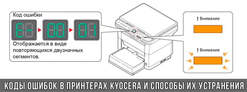
Коды ошибок принтеров и МФУ Kyocera, которые можно исправить самостоятельно
|
Код ошибки |
Значение ошибки |
Решение проблемы |
|
E-0001 (E1) |
Поврежден чип картриджа либо установлен неоригинальный картридж. |
Замените установленный картридж оригинальной версией изделия. Если хотите сэкономить, тогда купите и установите новый чип на картридж или перепрошейте принтер Kyocera. Однако предварительно не помешает попробовать сбросить ошибку соответствующей комбинацией клавиш (как это сделать, читайте в статье «Сброс ошибки установки неоригинального картриджа в принтерах Kyocera»). |
|
E-0002 (E2) |
Регион использования картриджа и принтера не совпадают. |
Замените чип или прошейте принтер Kyocera. |
|
E-0003 (E3) |
Заполнена память принтера или МФУ Kyocera. |
Отпечатайте ранее отсканированные листы или очистите очередь печати нажатием кнопки Стоп/Сброс (ранее отсканированные листы также удалятся из памяти принтера, даже если они еще не были распечатаны). |
|
E-0007 (E7) |
Тонер-картридж Kyocera израсходовал ресурс красящего вещества. |
Замените или заправьте картридж Kyocera (если используете совместимый или перезаправленный расходник, то после установки его в принтер не забудьте сбросить ошибку зажатием на 3-5 секунды кнопок [Ок] и [Сброс/Стоп]). |
|
E-0008 (E8) |
Открыта крышка принтера либо не работает датчик закрытия крышек устройства. |
Откройте и еще раз закройте переднюю и заднюю крышку принтера. Во время закрытия Вы должны услышать характерный щелчок. Если не помогло, то причина в неисправности датчика. |
|
E-0009 (E9) |
Лоток приема бумаги полон. |
Уберите все отпечатанные листы бумаги из выходящего лотка. Чтобы возобновить печать, нажмите кнопку [Старт]. |
|
E-0012 (E12) |
Ошибка памяти принтера Kyocera. |
Попробуйте уменьшить разрешение печати. Скорее всего, формат создаваемого отпечатка не соответствует возможностям принтера. |
|
E-0014 (E14) |
Установлен неверный формат бумаги (неподдерживаемый принтером Kyocera). |
Поменяйте бумагу на поддерживаемую принтером либо смените ее формат в настройках печати. Попробуйте обновить программное обеспечение. Возможно, это расширит поддерживаемые принтером Kyocera форматы. |
|
E-0015 (E15) |
Устройство не подключено к электрической сети либо на компьютере нет (не работает) драйвера принтера Kyocera. |
Проверьте подключение печатающего аппарата к электрической сети, а также целостность кабеля. Если ошибка не исчезает, скачайте драйвер принтера Kyocera и установите его на компьютер. |
|
E-0017 (E17) |
Ошибка передачи данных. |
Проверьте подключение принтера к компьютеру. Кабель не должен быть длиннее 5 метров, а также обязан поддерживать стандарт USB 2.0. Кроме того, переустановите драйвер принтера и утилиту Kyocera Client Tool. |
|
E-0018 (E18) |
Очередь печати заполнена. |
Очистите очередь печати нажатием кнопки [Сброс] либо через драйвер принтера. |
|
E-0019 (E19) |
Неверный формат печати. |
Отмените печать нажатием кнопки [Стоп/Сброс]. Выберите в настройках принтера соответствующий режим печати, а также установите в лоток поддерживаемый принтером формат бумаги. |
|
J-0000 (jam0000) |
Замятие бумаги за задней крышкой. |
Откройте крышку и извлеките бумагу. Проверьте надежность крепления бумаги в лотке, а также принтер на наличие посторонних предметов. Еще причина может быть в пружине выходного флажка. Если она растянулась, то может плохо работать фиксатор. Также проблема может быть из-за печки, сделайте ее ревизию, переборку и смазку. |
|
J-0501 (jam0501) |
Бумага застряла в принтере Kyocera |
Извлеките замятую бумагу. Проверьте надежность установки бумаги во входной лоток. Проверьте целостность роликов протяжки бумаги, а также принтер на наличие посторонних предметов. Если не помогло, стоит внимательно осмотреть ребра на направляющей пластине. На них могут образоваться сколы, трещины и заусенцы. Их можно слегка подчистить наждачной бумагой (нулевкой). |
|
J-0511 (jam0511) |
Принтер Kyocera замял бумагу. |
Извлеките замятую бумагу и повторите печать. Если проблема не исчезла, несите принтер в сервис. Скорее всего, изношен ролик протяжки бумаги. |
|
C7990 |
Бункер драм-картриджа (блока фотобарабана) заполнен отработанным тонером либо неисправен счетчик отработки красящего вещества. Еще проблема может быть в главной плате PWB. |
Осуществите чистку драм-картриджа (блока фотобарабана). Если проблема в датчике или плате, то нужно отнести принтер в СЦ на диагностику. |
|
F248 |
Ошибка обработки отпечатываемого материала. |
Перезагрузите принтер. Уберите неподдерживаемые спецсимволы из отпечатка. Обновите ПО принтера Kyocera. Смените режим работы принтера с PDL на GDI (Пуск -> Принтеры -> Свойства -> Параметры устройства). |
|
PF |
Отсутствует бумага в лотке подачи. |
Загрузите листы бумаги во входной лоток. Если принтер по-прежнему не печатает, значит нужно искать проблему в чем-то другом. |
|
1101 |
Ошибка сканирования через сеть из-за неправильного имени SMTP сервера. |
Пропишите DNS-адреса помимо прочих настроек печати по сети. |
|
1102 |
Некорректная настройка сканера для работы через сеть |
Зайдите в Web-панель управления принтером (нужно в адресную строку браузера ввести iP принтера Kyocera). Далее в зависимости от модели введите логин и пароль (Admin/Admin или просто admin00 без логина). Далее следуйте инструкции:
Логин и пароль нужны обязательно, если их нет, то следует создать. |
|
2101 |
Ошибка передачи данных при сканировании через сеть. |
Правильно настройте параметры (как для ошибки 1102), только предварительно отключите на ПК антивирус и брандмауэр. |
Если Вы испытали все способы, но не смогли убрать ошибку, то следует нести печатающее устройство в сервисный центр. Кроме того, есть ряд ошибок (высвечиваемых на дисплее принтера), которые нельзя устранить в домашних условиях. Соответствующие коды ошибок принтеров Kyocera представляем в очередной таблице.
Коды ошибок принтеров и МФУ Kyocera, которые нужно устранять в сервисном центре
|
Код ошибки |
Значение ошибки |
Решение проблемы |
|
0030 |
Неисправность платы управления факсом принтера. |
Замена платы. |
|
0100 |
Неисправность платы управления или флеш-памяти принтера. |
Замена платы. |
|
0120 |
Ошибка чтения mac-адреса из-за неисправности флеш-памяти принтера. |
Замена платы. |
|
0190 |
Неисправность платы управления или флеш-памяти принтера. |
Замена платы. |
|
0630 |
Неисправность платы управления принтера. |
Замена платы. |
|
1020 |
Неисправность мотора, привода или отсутствие контакта. |
Разборка принтера и замена изношенных частей. Проверка надежности подключений, замена разорванных (прогоревших) кабелей. Ремонт или замена привода мотора. |
|
1040 |
Неисправность мотора, привода или отсутствие контакта. |
Разборка принтера и замена изношенных частей. Проверка надежности подключений, замена разорванных (прогоревших) кабелей. Ремонт или замена привода мотора. |
|
2000 |
Неисправность главной платы управления, соединительного кабеля или привода принтера. |
Проверить ремни, шестерни и ролики привода. Смазать или заменить, если есть дефекты. Заменить привод или главную плату. |
|
3100 (C3100) |
Неисправность главной платы, привода сканера, датчика положения или нарушение целостности соединений. |
Проверить наличие разрывов и отсутствия контакта. Смазать или заменить изношенные элементы привода. Заменить привод, главную плату, датчик или соединительный кабель. Если Вам повезло, то возможно забыли отключить фиксатор блока сканера. |
|
3101 |
Сетевой кабель не подсоединен, или нарушена работа концентратора. Еще может быть из-за наличия вирусов в системе или неправильно заданным параметрам сервера SMTP. |
Проверить соединения, правильно настроить параметры сети. |
|
3300 |
Неисправность главной платы, датчика CIS или соединительного кабеля. |
Проверить контакты, заменить плату или датчик. |
|
3500 |
Неисправность главной платы или нарушение соединения контактов. |
Проверить контакты, заменить плату. |
|
4000 (C4000) |
Неисправность главной платы, привода сканера или нарушение соединений. Однако чаще всего ошибка лазера. |
Проверить контакты, заменить плату или привод блока сканера. Почистить лазер, смазать ось полигон-мотора, либо полностью заменить блок лазера. |
|
4200 |
Неисправность главной платы, блока сканера или датчика BD. |
Отключить питание принтера на 30 минут. Если не помогло, то следует заменить привод сканера или главную плату принтера. |
|
6000 (С6000) |
Неисправность главной платы, термостата, печки или нарушение соединения контактов. |
Проверить и поправить контакты. Заменить фьюзер. Ремонт или замена печки, термодатчика, термопредохранителя и т.д. |
|
6020 |
Сгорание термистора или главной платы. |
Замена термистора или главной платы. |
|
6030 |
Неисправность главной платы, термостата или термистора. Возможно, причина в отсутствии контакта. |
Проверить соединения. Заменить плату, термостат или термистор. |
|
6400 |
Неисправность главной платы, отсутствие питания или контакта. |
Заменить плату или источник питания. |
|
F000 |
Неисправность главной платы или отсутствие контакта. |
Проверить соединение ремня безопасности. Заменить ремень или плату управления. |
|
F020 |
Неисправность элементов памяти принтера. |
Перезагрузить принтер. Если ошибка не устранилась – заменить плату управления. |
|
F040 |
Неисправность главной платы принтера. |
Перезагрузить принтер. Если ошибка не устранилась – заменить плату управления. |
|
F05D |
Неисправность главной платы. Сбой программного оборудования привода. Проблемы с прошивкой принтера Kyocera. |
Перезагрузить принтер. Если ошибка не устранилась – заменить плату управления. Перепрошить принтер Kyocera. |
|
F245 F246 F247 F375 |
Принтер Kyocera заблокирован из-за проблемы, вызванной отказом источника питания. |
Нужно перепрошить принтер специальной сервисной микропрограммой. |
Обратите внимание: Если у печатающего устройства нет дисплея, то определить проблему можно по светодиодным индикаторам, встроенным в панель управления принтером. Например, у Kyocera Ecosys P2135D нужно сосчитать количество миганий индикаторов красного цвета и таким образом определить число, указывающее на ту или иную ошибку. В свою очередь, у модели Kyocera FS-1040 все зависит от темпа мигания светодиода с надписью «Внимание!» («Attention!»):
- Мигает медленно – указывает на отсутствие бумаги в лотке или тонера в картридже.
- Мигает быстро – оповещает о проблеме с памятью устройства, переполненном лотке или замятии бумаги, а также об использовании неоригинальных расходных материалов.
- Горит постоянно – говорит о проблемах с картриджем или фотобарабаном либо указывает на открытые крышки принтера.
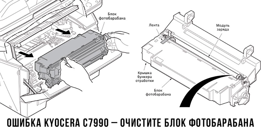
Чтобы потребитель мог наверняка определить проблему, рекомендуем использовать утилиту Kyocera Client Tool, которая идет в комплекте с драйверами принтера.
Ваше Имя:
Ваш вопрос:
Внимание: HTML не поддерживается! Используйте обычный текст.
Оценка:
Плохо
Хорошо
Введите код, указанный на картинке:

We solved the issue however I could not find anything that was even remotely useful online, so here is my contribution to the wider IT community.
Me and a coworker encountered an issue with our Kyocera P3155dn, where the printer would keep showing the error code F46F. We tried to find what it means however Kyocera does not have a very well maintained / easy to get list with error codes for each printer which explain what it means. The best we could find was this page which some of the error codes that Kyocera uses.
When checking on the printer itself we noticed that one job was always listed in the Printing Job List. When we tried to remove the printjob via the Webinterface it stayed as canceling even after multiple restarts of the device + a «factory reset» via Webinterface.
The printer was added via a print-server and we selected the KPDL-Driver as it was the only driver that worked with our program which selects the paper-tray and does not work with the KX or XPS driver. Additionally I would like to mention that the printer was working fine for about a month as locally installed and about a week as a printserver printer.
We also noticed that the printer did sometimes print out the other jobs waiting after a restart and then once it was done it printed page 1 of the job and got stuck again. When unplugging the network cable, it was possible to navigate the menu, print out the usual reports etc. The last hint I got was when the PC was shut off and the printer worked fine with every other PC I tested.