
Рекомендованные сообщения
liqvidator
17
-
- Жалоба
- Рассказать
Здравствуйте коллеги.
На фрезерном ОЦ (3х осевом) с Fanuc 0i-MD возникли проблемы. При включении станка выдает ошибки:
SP1220 (S) ОТСУТ. УСИЛ. ШПИН
SV5136 FSSB: Сила тока недостаточна
На частотном усилителе A06B-6164-H343#H580 сразу после включения загорается индикатор ALM.
После загрузки станка и отжатия аварийного останова на катушку главного электромагнитного пускателя не приходит 110V.
Между фазами напряжение 223В, а относительно заземления 150В, 136В, 114В.
- Цитата
Ссылка на сообщение
Поделиться на других сайтах
bfi
99
-
- Жалоба
- Рассказать
поищите в сообщениях 5136, скоро писал, может где-то к.з. на линии +5В, тогда привод не отвечает ЧПУ, итог-5136
Ссылка на сообщение
Поделиться на других сайтах
liqvidator
17
- Автор
-
- Жалоба
- Рассказать
В 17.05.2018 в 10:49, bfi сказал:
поищите в сообщениях 5136, скоро писал, может где-то к.з. на линии +5В, тогда привод не отвечает ЧПУ, итог-5136
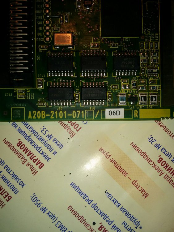
Прозвонил все разъемы энкодеров — всё ОК. Решил делать свап плат чтобы понять какая плата вышла из строя. Снял плату A20B-2101-0711/06DR и поменял с аналогичной A20B-2101-0029/02B, ошибка исчезла. Привод заработал. То ли микротрещина где то на родной плате, то ли понять не могу почему так система себя ведёт. Плату несколько раз спиртом с щёткой почистил. Поставил снова родную — итог станок проработал минуты 2 потом снова ушёл в защиту. Плату меняю система опять работает.
- Цитата
Ссылка на сообщение
Поделиться на других сайтах

Viktor2004
605
-
- Жалоба
- Рассказать
У меня была микротрещина на процессорной плате ЧПУ. Когда надавливал на середину и чуть-чуть пальцами отгибал края, все работало. Как только отпускал, сразу отказ. Найти дефект на плате оказалось нереально. Слишком плотный монтаж с BCD-корпусами чипов. Только менять. При чем фанук платы просто так не продает, обязательно приезжает сам, меняет и забирает неисправную плату с собой. Еще и за его приезд надо денег вывалить. Есть вариант купить в Кетае. Это дешевле, но и рискованнее.
- Цитата
Ссылка на сообщение
Поделиться на других сайтах
liqvidator
17
- Автор
-
- Жалоба
- Рассказать
Сейчас чистил плату и снова поменял местами. Включил контроллер и станок загрузился, ошибка была только Emergency Stop. Простоял минуты 3-4 потом снова вылетел.
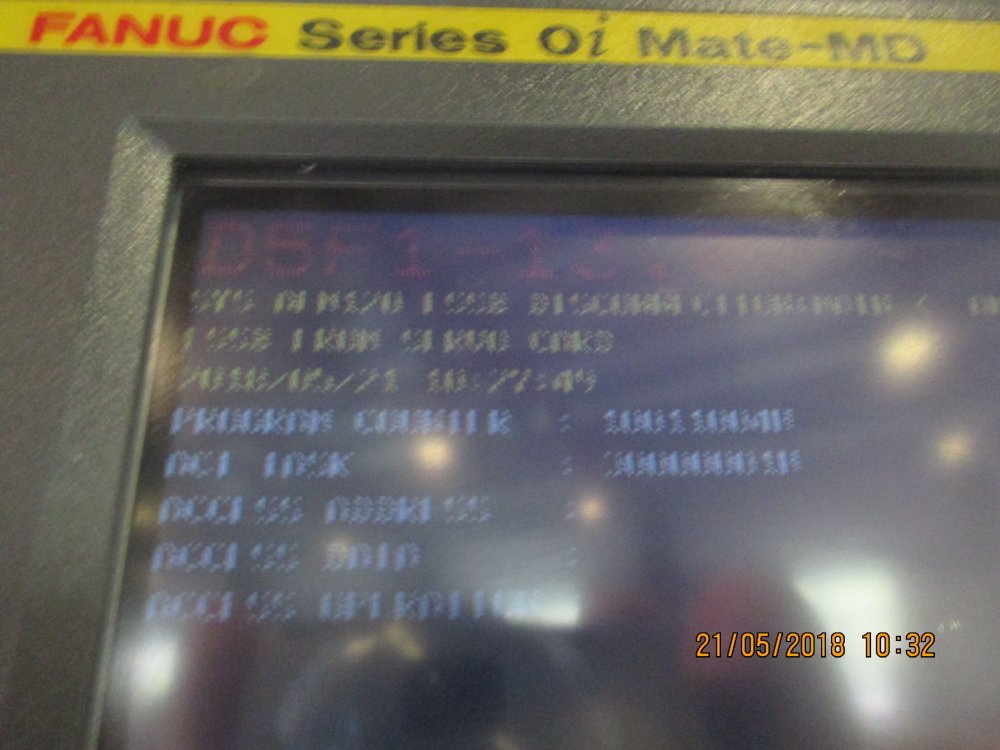
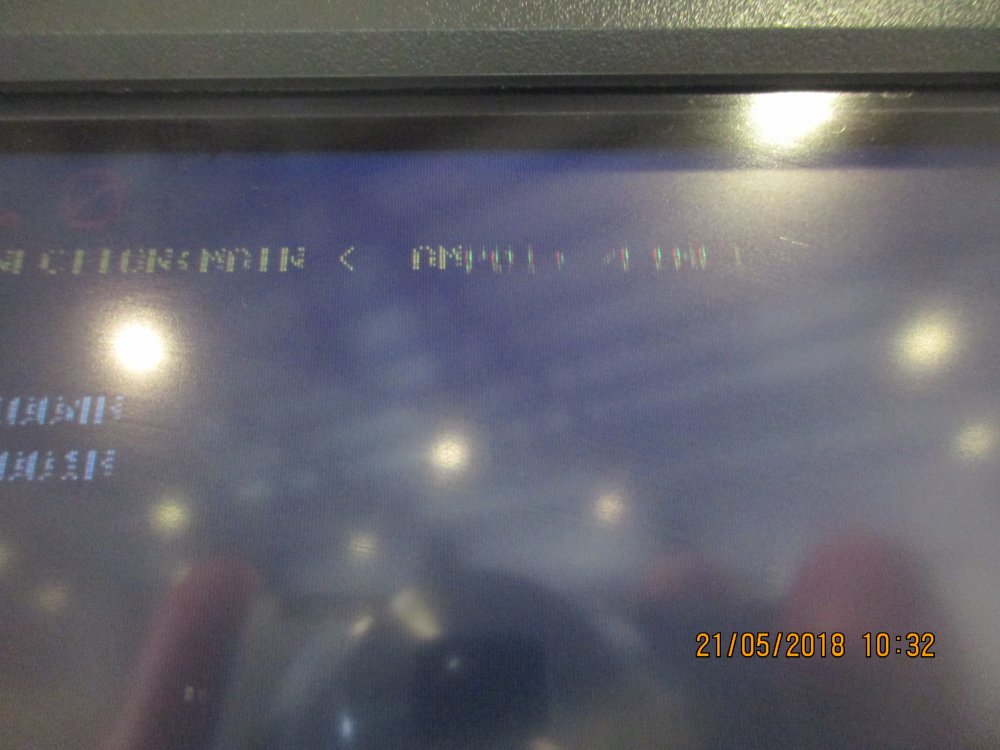
SYS ALM 120 FSSB DISCONNECTION MAIN + «7 страниц кодов» было. Монитор залитый был когда-то из-за этого матрица повреждена и изображение на нём не четкое.
Ну и разумеется после этого он перестал работать снова.
По существу 3 вопроса:
1. Можно ли прямо в разъём FSSB заливать спирт? Но я так понимаю туда лучше ничем не лазить?
2. Можно ли FSSB разъемы перепаять местами? Плата многослойная и на просвет непонятно есть ли там внутренние дорожки, хотя скорей всего есть.
3. По какому принципу подбирать плату? Я так понимаю A20B-2101-0711 далее уже что будет написано это без разницы или нет?
Изменено 21 мая 2018 пользователем liqvidator
- Цитата
Ссылка на сообщение
Поделиться на других сайтах
liqvidator
17
- Автор
-
- Жалоба
- Рассказать
Обратил внимание, что при возникновении данной ошибки и состояния индикация COP10A и COP10B горит в «полнакала».
- Цитата
Ссылка на сообщение
Поделиться на других сайтах
Viktor2004
605
-
- Жалоба
- Рассказать
Разъем FSSB зачем перепаивать? Там оптика. Промыть ее можно. Там светодиод и фотодиод. Думаю перепайка нанесет больше вреда чем пользы.
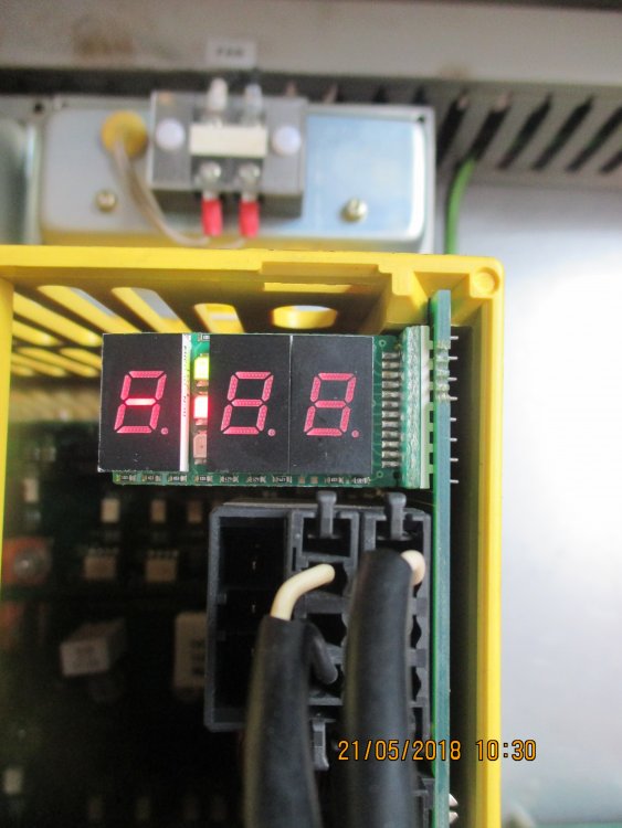
Плату лучше искать такую же. Из-за несовпадения версии софта прошивки платы, оно не будет работать. Версия прошивки смотрится при включении блока. Там на 7-сегментном индикаторе начинают по очереди загораться буквы, цифры, дефисы. Их надо переписать. Какой-то софт совместим, какой-то нет, этого никто не скажет.
Это плата осевого привода или шпиндельного? Вроде изначально ошибки были на двух приводах
- Цитата
Ссылка на сообщение
Поделиться на других сайтах
liqvidator
17
- Автор
-
- Жалоба
- Рассказать
1 час назад, Viktor2004 сказал:
Разъем FSSB зачем перепаивать? Там оптика. Промыть ее можно. Там светодиод и фотодиод. Думаю перепайка нанесет больше вреда чем пользы.
Плату лучше искать такую же. Из-за несовпадения версии софта прошивки платы, оно не будет работать. Версия прошивки смотрится при включении блока. Там на 7-сегментном индикаторе начинают по очереди загораться буквы, цифры, дефисы. Их надо переписать. Какой-то софт совместим, какой-то нет, этого никто не скажет.
Это плата осевого привода или шпиндельного? Вроде изначально ошибки были на двух приводах
Станок 0i-Mate там beta привод один на все оси + шпиндель (beta i SVSP 40/40/80-15).
- Цитата
Ссылка на сообщение
Поделиться на других сайтах
Anat2015
303
-
- Жалоба
- Рассказать
1 час назад, liqvidator сказал:
там beta привод один на все оси + шпиндель
Это не привод, это модуль приводов, контроль каждой координаты идет индивидуально
- Цитата
Ссылка на сообщение
Поделиться на других сайтах
liqvidator
17
- Автор
-
- Жалоба
- Рассказать
Попробую завтра найти кондёры и все заменить. SMD-шные не буду трогать. Если б был транзистор сразу бы ошибку выдавала, а кондёр что-то мне кажется может периодически и работать.
На силовой то плате бывало что приходилось пропаивать нижние резисторы по 30кОм на подобных плат, там из-за нагрева что ли бывает в пайке микротрещины образуются.
- Цитата
Ссылка на сообщение
Поделиться на других сайтах
![]()
vl_cnc
85
-
- Жалоба
- Рассказать
В 22.05.2018 в 16:15, liqvidator сказал:
SMD-шные не буду трогать.
Несколько раз приходилось ремонтировать платы фануковских драйверов, и проблема была именно в SMD конденсаторах, они не долговечны, лучше менять все сразу и на 105-ти градусные. Но в моё случае ошибки были другие, и с прогревом около 15-20 минут драйвера начинали работать нормально.
Ссылка на сообщение
Поделиться на других сайтах
- 4 недели спустя…
liqvidator
17
- Автор
-
- Жалоба
- Рассказать
Эпопея закончилась — заменой платы A20B-2101-0711/06DR — станок YOPM поставщик из Москвы периодически в течении гарантии появлялась данная ошибка, ну и как всегда Москвичи не добили проблему. Менял кондёры и компараторы (потому что у одно нога отпавшая была когда под лупой смотрел) — результата не дало.
- Цитата
Ссылка на сообщение
Поделиться на других сайтах
- 3 года спустя…
Дмитрий К
0
-
- Жалоба
- Рассказать
А где установлена эта плата A20B-2101-0711/06DR на станке
- Цитата
Ссылка на сообщение
Поделиться на других сайтах
gudstartup
492
-
- Жалоба
- Рассказать
2 часа назад, Дмитрий К сказал:
А где установлена эта плата A20B-2101-0711/06DR на станке
Это плата управления приводом и находится непосредственно в нем.
- Цитата
Ссылка на сообщение
Поделиться на других сайтах
- 6 месяцев спустя…
Slon4es
0
-
- Жалоба
- Рассказать
Добрый день. Похожая проблема, те же ошибки. После включения главного рубильника нет никакой индикации ни на одном из серво приводов.
- Цитата
Ссылка на сообщение
Поделиться на других сайтах
Viktor2004
605
-
- Жалоба
- Рассказать
2 часа назад, Slon4es сказал:
После включения главного рубильника нет никакой индикации ни на одном из серво приводов.
Какой PSM у вас стоит?
А еще лучше электросхему дайте нам посмотреть
- Цитата
Ссылка на сообщение
Поделиться на других сайтах
Присоединяйтесь к обсуждению
Вы можете опубликовать сообщение сейчас, а зарегистрироваться позже.
Если у вас есть аккаунт, войдите в него для написания от своего имени.
Примечание: вашему сообщению потребуется утверждение модератора, прежде чем оно станет доступным.
-
05-17-2018, 08:05 AM
#1

Registered
Hello.
I have a problem with 3rd axial milling center on Fanuc 0i-Mate-MD. I see two troubles after machine power on:
SP1220 (S)
SV5136 FSSB: Current is insufficient
Also servo amplifier A06B-6164-H343#H580 indicated the ALM status lights up after power on CNC-controller.
And doesn’t come to the coil of the main electromagnetic actuator 110V (MCC).
I check the voltage between phases tension 223V, and concerning grounding 150V, 136V, 114V.
What need I do now for checking and repair machine?
-
05-17-2018, 08:49 AM
#2
Member
Re: Need Help! Error SV5136 & SP1220 & not activated MCC
did you measure voltage between all phases R-S S-T R-T?
-
05-17-2018, 09:21 AM
#3
Registered
Re: Need Help! Error SV5136 & SP1220 & not activated MCC
Originally Posted by guhl
did you measure voltage between all phases R-S S-T R-T?
Yes. 223V between all phases after transformer, but between phase and ground other voltage: 150V, 136V, 114V.
-
05-17-2018, 02:23 PM
#4
Member
Re: Need Help! Error SV5136 & SP1220 & not activated MCC
what’s on the drive’s led display inside the control cabinet?
-
05-21-2018, 08:34 AM
#5
Registered
Re: Need Help! Error SV5136 & SP1220 & not activated MCC
Originally Posted by guhl
what’s on the drive’s led display inside the control cabinet?
Yesterday I made a replacement management card for verification. I removed the board A20B-2101-0711 / 06DR and supplied the A20B-2101-0711 / 02AR. The machine worked stably for 1 hour.
Then I changed the boards again. The system started up and booted and worked for 3 minutes. Then again, the indication greed & red on the servo amplifier and the error on the display SYS_ALM_120 FSSB DISCONNECTION MAIN.
-
05-22-2018, 08:11 AM
#6
Member
Re: Need Help! Error SV5136 & SP1220 & not activated MCC
I would change all electrolitic capacitiors on PCBs. at least in servo drives
-
12-05-2018, 02:49 PM
#7
Junior Member
Re: Need Help! Error SV5136 & SP1220 & not activated MCC
I have a problem i feel is in the same area of the servo amplifiers, MCC, and emergency stop that is tied into this circuit
I have a 1985 Amada OCTO 334 with Fanuc System 6M Series M31 Version 03 controller. Monday morning came to turn the machine on and it has a external alarm 14: Emergency/Reset. Did some testing in the area of it being a problem with the EMG switch or circuit( tested relays, changed switched etc .) I was suggested by amada service in CA to jump 205 with any common 200.(205=*WEM emergency stop switch) when i did this the machine no longer had code 14, but then a code 401 Servo.: The ready signal (VRDY) for velocity control of X-,Y-,or T-axis is off.
So from what i have learned so far is that , the code 14 is a builders alarm , based off a initial system check , NC is not ready . My guess something to do with the servo’s since when i jump 205 it then gives me 401 alarm. So i started with basics. i cleaned the brushes and cleaned out the dust. then topped off the fluid.
a bit more information.
The servo amplifiers(and if i have this correctly are also the velocity control unit ) have two led green lights. on the boards it says RDY with a small v slightly above it but could possibly belong to something else on the board, and the other light has PRDY(positional control). . Only the RDY light is lit on all X-,Y-,Z(T)and C the auto-index.Behind all these PCB is several components like two breakers,terminal boards,MCC, thermal relay etc. the magnetic contactor is supposed to send the signal to the servos and then recieve a ready signal back, right? Well it looks like these MCC’s don’t suck the center tab in like a much bigger magnetic contactor on the input signal board does when i turn on the power . Wonder if that is telling me anything or if they aren’t activating because the problem could be before the signal even gets that far .
Help would be greatly appreciated
Thanks
-
12-05-2018, 07:11 PM
#8
Member
Re: Need Help! Error SV5136 & SP1220 & not activated MCC
SV 5136 is number of AMPLIFIERS is small. The amps reporting to the control and the FSSB settings dont match. Lots of times the fiber optic cable is broken from COP10B — COP10A.
-
12-06-2018, 02:30 AM
#9
Junior Member
I second ‘freakycnc’ comment. Check fiber cables first.
Plus its easier than the capacitors on the first pass unless you already have it opened up.
-
05-05-2021, 11:40 AM
#10
the same problem if any one can help
-
06-03-2022, 07:23 PM
#11
Re: Need Help! Error SV5136 & SP1220 & not activated MCC
Originally Posted by Semoogad
the same problem if any one can help
That seems that the Spindle Amplifier isn’t working.— — — Updated — — —
Originally Posted by Semoogad
the same problem if any one can help
That seems that the Spindle Amplifier isn’t working.


доброго времени суток. у меня слетела система с fanuc oi-mc, систему я восстановил,найдя копии у поставщика,но возникли проблемы с лицензией. надпись ,о ней будет говорят 30 дней мигать ,а потом станок зависнет,но пока не до неё. после запуска системы ,через какое-то время система выкинула ошибку 926-ошибка FSSB и мелким шрифтом были написаны адреса ошибки. после перезагрузки ,через некоторое время опять тоже самое.наладчик сказал,что перед тем,как слетела система было тоже . нашёл неисправность чисто случайно ,стал проверять не оборвались ли где кабеля датчиков осей,и обнаружил,что корпус датчика х очень горячий. разобрал,оказалось,что один из штырьков разъёма отвалился практически от шлейфа(мои предположения,так как само место пайки залито,а ковырять я побоялся),что идёт на плату датчика. и вот этот штырёк так грелся,что вокруг него был обугленный материал .штырёк я убрал совсем ,кинул проводок напрямую,собрал и о чудо-ошибки больше не появлялось (926). стал проверять настройки осей и усилителей,данные о двигателях осей и шпинделе оказалось всё пусто,стал пытаться через автоматическую установку произвести установку, бесполезно. появились только данные о двигателях осей . много делал попыток,параметры разные менял ,бесполезно,стойка пишет ошибка 750 и ошибка-недостаточно усилителей 5136 (конечно недостаточно ,их вообще нет и не устанавливаются). потом откинул разъём датчика х , выключив станок, загрузил и вот всё появилось и характеристики двигателя шпинделя,и его серийный номер,и 4 усилителя с токовыми характеристиками(оси 4-и),все ошибки пропали,появилась только ошибка х 368(нельзя получить данные от встроенного импульсного шифратора) и это правильно,разъём датчика х то откинут. и вот я выключаю станок ,одеваю разъём датчика х,с надеждой ,что параметры не исчезнут…Но нет ,опять нет параметров двигателя шпинделя,нет ни одного усилителя… снял снова разъём х ,загрузил ,вуаля, параметры на месте. если вы дочитали хочу у вас спросить ,может что подскажете,что не так,это датчик или всё же с конфигурацией что-то не так? заменить бы датчик ,да нечем. или может подскажете ,как его обойти ,убедится ,что это он ,а не что иное.
- Ответ
- Жалоба
- И
Изменено 16.11.2016 15:35 пользователем Alescaput82
A FANUC alarm code, also called a FANUC fault or error code, is how a CNC control indicates there is a problem. This error message could indicate issues with either the machine itself, be that electric or mechanical. The FANUC error code might also indicate an issue with the g-code program.
Use the list below to interpret what exactly the fault code is trying to communicate. If you require a replacement part, know that MRO Electric stocks thousands of FANUC CNC replacements. Get your new FANUC servo amplifier or check out our FANUC servo motors. To order a replacement part or a repair job, please call 800-691-8511 or email sales@mroelectric.com. Curious about other common FANUC CNC problems? Check out our FAQ here.
• 0i Model A
• 0i/0iMate Model B
• 16/18 Model PB
• 16/18 Model C
• 16i/18i Model A
• 16i/18i Model B
• 16iL Model A
• 20i
• 21 Model B
• 21i Model A
• 21i Model B
• 21i Model A

Добавил:
Upload
Опубликованный материал нарушает ваши авторские права? Сообщите нам.
Вуз:
Предмет:
Файл:
Скачиваний:
785
Добавлен:
21.03.2015
Размер:
6.94 Mб
Скачать
![]()
|
B—64144RU/01 |
ПРИЛОЖЕНИЕ |
G. СПИСОК СИГНАЛОВ ТРЕВОГИ |
|
Номер |
Сообщение |
Содержание |
|
130 |
ILLEGAL AXIS OPERATION |
Команда осевого управления выдана PMC для оси, |
|
(НЕВЕРНАЯ ОПЕРАЦИЯ ПО ОСИ) |
управляемойЧПУ. Иликомандаосевогоуправлениявыдана |
|
|
ЧПУ для оси, управляемой РМС. Измените программу. |
||
|
131 |
TOO MANY EXTERNAL ALARM MESSAGES |
Вовнешнемаварийномсообщенииуказаныпятьилибольше |
|
(СЛИШКОМ МНОГО ВНЕШНИХ |
сигналов тревоги. |
|
|
АВАРИЙНЫХ СООБЩЕНИЙ) |
Для выяснения причины смотрите цепную схему PMC. |
|
|
132 |
ALARM NUMBER NOT FOUND |
При удалении внешнего аварийного сообщенияотсутствует |
|
(НЕ НАЙДЕННОМЕР СИГНАЛАТРЕВОГИ) |
номер соответствующего сигнала тревоги. |
|
|
Проверьте цепную схему PMC. |
133ILLEGAL DATA IN EXT. ALARM MSG (НЕВЕРНЫЕ ДАННЫЕ ВО ВНЕШНЕМ АВАРИЙНОМ СООБЩЕНИИ)
135ILLEGAL ANGLE COMMAND (НЕВЕРНОЕ ПРОГРАММИРОВАНИЕ УГЛА)
136ILLEGAL AXIS COMMAND (НЕВЕРНОЕ ПРОГРАММИРОВАНИЕ ОСИ)
141CAN NOT COMMAND G51 IN CRC (НЕЛЬЗЯ ПРОГРАММИРОВАТЬ G51 В CRC)
142ILLEGAL SCALE RATE (НЕВЕРНЫЙ КЛАСС ШКАЛЫ)
Неверны данные небольшого раздела во внешнем аварийном сообщении или внешнем сообщении для оператора. Проверьте цепную схему PMC.
Угол позиционирования индексации таблицы индексов был задан иначе, чем кратным целым значения минимального угла. Измените программу.
При индексировании таблицы индексов задана другая контрольная ось вместе с осью B. Измените программу.
G51 (Scaling ON (масштабирование включено)) запрограммирован в режиме коррекции на инструмент.
Измените программу.
Увеличение масштабирования программируется иначе, чем с использованием 1 — 999999. Исправьте установку увеличения масштабирования (G51 Pp . . . или параметр
5411, или 5421).
143SCALED MOTION DATA OVERFLOW (ПЕРЕПОЛНЕНИЕ ДАННЫХ ПО МАСШТАБИРУЕМОМУ ДВИЖЕНИЮ)
144ILLEGAL PLANE SELECTED (НЕВЕРНО ВЫБРАНА ПЛОСКОСТЬ)
148ILLEGAL SETTING DATA (НЕВЕРНЫЕ ДАННЫЕ УСТАНОВКИ)
149FORMAT ERROR IN G10L3 (ОШИБКА ФОРМАТА В G10L3)
150ILLEGAL TOOL GROUP NUMBER (НЕВЕРНЫЙ НОМЕР ГРУППЫ ИНСТРУМЕНТОВ)
151TOOL GROUP NUMBER NOT FOUND (НЕ НАЙДЕН НОМЕР ГРУППЫ ИНСТРУМЕНТОВ)
Результаты масштабирования, расстояние перемещения, значение координаты и радиус круга превышают макс. программное значение. Исправьте программу или увеличение масштабирования.
Плоскость координатного вращения и плоскость дуги или компенсации на режущий инструмент С должны совпадать. Измените программу.
Уровень замедления автоматического изменения скорости подачи при обработке углов находится вне устанавливаемого диапазона оцениваемого угла. Измените параметры
(ном.1710-1714)
При расширенном управлении ресурсом инструмента в качестветипаучетаресурсазаданкод, кроме Q1, Q2, P1 или
P2.
Номер группы инструментов превышает максимально допустимое значение. Измените программу.
Не установлена группа инструментов, заданная в программе обработки. Измените значение в программе или параметре.
|
152 |
NO SPACE FOR TOOL ENTRY (НЕТ МЕСТА |
Число инструментов в одной группе превышает макс. реги- |
|
ДЛЯ ВВОДА ИНСТРУМЕНТА) |
стрируемое значение. Измените количество инструментов. |
|
|
153 |
T-CODE NOT FOUND |
При регистрации данных ресурса инструмента Т-код не |
|
(НЕ НАЙДЕН Т-КОД) |
был задан в блоке, в котором он требуется. Или же только |
|
|
M06 был задан в блоке для замены инструмента типа D. |
||
|
Исправьте программу. |
||
|
154 |
NOT USING TOOL IN LIFE GROUP |
Если группа не программируется, H99 или D99 не запро- |
|
(НЕ ИСПОЛЬЗУЕТСЯ ИНСТРУМЕНТ В |
граммированы. Исправьте программу. |
|
|
ГРУППЕ РЕСУРСА) |
||
|
155 |
ILLEGAL T-CODE IN M06 |
В программе обработки М06 и Т-код водном итом жеблоке |
|
(НЕВЕРНЫЙ Т-КОД В М06) |
не соответствуют используемой группе. Исправьте |
|
|
программу. |
817

|
G. СПИСОК СИГНАЛОВ ТРЕВОГИ |
ПРИЛОЖЕНИЕ |
B—64144RU/01 |
Номер Сообщение
156P/L COMMAND NOT FOUND (НЕ НАЙДЕНА КОМАНДА P/L)
157TOO MANY TOOL GROUPS (СЛИШКОМ МНОГО ГРУПП ИНСТРУМЕНТОВ)
158ILLEGAL TOOL LIFE DATA (НЕВЕРНЫЕ ДАННЫЕ РЕСУРСА СТОЙКОСТИ ИНСТРУМЕНТА)
159TOOL DATA SETTING INCOMPLETE (НЕЗАВЕРШЕНА УСТАНОВКА ДАННЫХ ИНСТРУМЕНТА)
177CHECK SUM ERROR
(ОШИБКА КОНТРОЛЬНОЙ СУММЫ) (G05 MODE)(РЕЖИМ G05)
178G05 COMMANDED IN G41/G42 MODE
(G05 ЗАПРОГРАМИРОВАН В РЕЖИМЕ
G41/G42)
190ILLEGAL AXIS SELECT (НЕВЕРНЫЙ ВЫБОР ОСИ)
199MACRO WORD UNDEFINED
(НЕ ОПРЕДЕЛЕНО МАКРОСЛОВО)
200ILLEGAL S CODE COMMAND (НЕВЕРНАЯ КОМАНДА S-КОДА)
201FEEDRATE NOT FOUND IN RIGID TAP (В РЕЖИМЕ ЖЕСТКОГО НАРЕЗАНИЯ РЕЗЬБЫ МЕТЧИКОМ НЕ НАЙДЕНА СКОРОСТЬ ПОДАЧИ)
202POSITION LSI OVERFLOW (ПЕРЕПОЛНЕНИЕ БИС ПОЛОЖЕНИЯ)
203PROGRAM MISS AT RIGID TAPPING (ПРИ ЖЕСТКОМ НАРЕЗАНИИ РЕЗЬБЫ МЕТЧИКОМ ИМЕЕТСЯ ПРОГРАММНОЕ НЕСООТВЕТСТВИЕ)
204ILLEGAL AXIS OPERATION (НЕВЕРНАЯ ОПЕРАЦИЯ ПО ОСИ)
205RIGID MODE DI SIGNAL OFF (СИГНАЛ DI ЖЕСТКОГО РЕЖИМА ВЫКЛЮЧЕН)
206CAN NOT CHANGE PLANE (RIGID TAP) (НЕЛЬЗЯ ЗАМЕНИТЬ ПЛОСКОСТЬ (ЖЕСТКОЕ НАРЕЗАНИЕ РЕЗЬБЫ)
207RIGID DATA MISMATCH (НЕСООТВЕТСТВИЕ ДАННЫХ ЖЕСТКОГО РЕЖИМА)
Содержание
В заголовке программы, в которой задана группа инструментов, отсутствуют команды P и L. Исправьте программу.
Устанавливаемое количество групп инструментов превышаетмаксимальнодопустимоезначение. См. параметрGS1, GS2 (ном. 6800 бит 0 и 1). Измените программу.
Устанавливаемый ресурс стойкости инструмента слишком велик. Измените устанавливаемое значение.
В процессе выполнения программы установки данных ресурса стойкости отключено питание. Установите данные снова.
Проверьте контрольную сумму Измените программу.
G05 запрограммирован в режиме G41/G42. Исправьте программу.
Приконтролепостоянстваскоростирезанияневернозадана ось. (Смотрите параметр ном. 3770) Заданная команда по оси(Р) содержитневерноезначение. Исправьтепрограмму.
Использовано неопределенное макрослово. Измените макропрограмму пользователя.
Врежиме жесткого нарезания резьбы метчиком, задано значение S, не входящее в диапазон, или не задано совсем. Максимальное значение для S, которое можно задать при жестком нарезании резьбы метчиком установлено в параметре (ном. 52415243). Замените установку в параметре или измените программу.
Врежиме жесткого нарезания резьбы метчиком не задано значение F. Исправьте программу.
Врежиме жесткого нарезания резьбы метчиком слишком большая величина распределения импульсов для шпинделей.
Врежиме жесткого нарезания резьбы метчиком неверно положение М-кода жесткого режима (М29)
или S-команды. Измените программу.
Врежиме жесткого нарезания резьбы метчиком между блоком М-кода жесткого режима (М29) и блоком G84 (G77) задано перемещение по оси. Измените программу.
Когда выполняется G84 (G88), несмотря на то, что задан М-код жесткого режима (M29), сигнал жесткого нарезания резьбы метчиком (DGNG061 #1) не — 1.
Смотрите цепную схему РМС для выяснения причины, по которой сигнал не был включен.
Переключение плоскости было задано в жестком режиме. Исправьте программу.
При жестком нарезании резьбы метчиком заданное расстояние — слишком короткое или слишком длинное.
818

|
B—64144RU/01 |
ПРИЛОЖЕНИЕ |
G. СПИСОК СИГНАЛОВ ТРЕВОГИ |
Номер Сообщение
210CAN NOT COMAND M198/M99 (НЕЛЬЗЯ ЗАПРОГРАММИРОВАТЬ
M198/M99)
224RETURN TO REFERENCE POINT (ВОЗВРАТ В РЕФЕРЕНТНУЮ ТОЧКУ)
231ILLEGAL FORMAT IN G10 OR L50 (НЕВЕРНЫЙ ФОРМАТ В G10 ИЛИ L50)
232TOO MANY HELICAL AXIS COMMANDS (СЛИШКОМ МНОГО КОМАНД С ВИНТОВОЙ ОСЬЮ)
233DEVICE BUSY (УСТРОЙСТВО ЗАНЯТО)
239BP/S ALARM (СИГНАЛ ТРЕВОГИ BP/S)
240BP/S ALARM (СИГНАЛ ТРЕВОГИ BP/S)
253G05 IS NOT AVAIRABLE
(G05 НЕ ДОСТУПЕН)
5010 END OF RECORD (КОНЕЦ ЗАПИСИ)
5020 PARAMETER OF RESTART ERROR (ОШИБКА ПАРАМЕТРА ПЕРЕЗАПУСКА)
5073 NO DECIMAL POINT
(НЕТ ДЕСЯТИЧНОЙ ТОЧКИ)
5074 ADDRESS DUPLICATION ERROR (ОШИБКА ДУБЛИРОВАНИЯ АДРЕСА)
5110 IMPROPER G-CODE (G05.1 Q1 MODE) (НЕПРАВИЛЬНЫЙ G-КОД
(РЕЖИМ G05.1 Q1))
5111 IMPROPER MODAL G-CODE (G05.1 Q1) (НЕПРАВИЛЬНЫЙ МОДАЛЬНЫЙ G-КОД
(РЕЖИМ G05.1 Q1)
5112 G08 CAN NOT BE COMMANDED (G05.1 Q1) (НЕЛЬЗЯ ЗАПРОГРАММИРОВАТЬ G08 (G05.1 Q1))
5114 NOT STOP POSITION (G05.1 Q1) (ПОЗИЦИЯ НЕОСТАНОВА) (G05.1 Q1)
Содержание
1)ВоперациипланированиявыполненыМ198 иM99. Илив операции группового ЧУ выполнен М198.
2)В многократно повторяющемся постоянном цикле фрезерования глубоких выемок задана макропрограмма прерывания и выполнен М99.
Возврат в референтное положение не был выполнен до начала автоматической операции. Выполните возврат в референтное положение, только если параметр ZRNX (ном.1005#0) соответствует 0.
При вводе программируемого параметра возникла одна из следующих ошибок в заданном формате.
1)Не введен адрес N или R.
2)Введен номер, не предусмотренный для параметра.
3)Слишком большой номер оси.
4)Не задан номер оси в параметре осевого типа.
5)Номер оси задан в параметре, который не является параметром осевого типа.
6)Сделана попытка переустановить разряд 4 параметра 3202 (NE9) или изменить параметр 3210 (PSSWD), когда они защищены паролем. Исправьте программу.
В режиме винтовой интерполяции заданы две или три оси в качестве винтовых осей.
При попытке использовать устройство, например, устройство, подсоединенное через интерфейс RS-232-C, обнаружено, что оно используется другими пользователями.
Фоновое редактирование выполнялось в процессе вывода данных на перфоленту с применением функции управления внешними устройствами ввода-вывода.
Фоновое редактирование выполнялось во время операции ручного ввода данных.
Операция двойного ввода с высокоскоростным удаленным буфером (G05) или высокоскоростной циклической обработкой (G05) задана в режиме предварительного управления (G08P1). До попытки задать эти команды сначала задайте G08P0 ; для отмены режима предварительного управления.
Задан конец записи (%).
Параметр, задающий перезапуск программы, установлен неправильно.
Не задана десятичная точка для команды, в которой обязательно указание десятичной точки.
Один и тот же адрес указан в блоке более одного раза. Или блок содержит два или более G-кодов, принадлежащих к одной группе.
В режиме управления с предпросмотром AI был задан неверный G-код.
НеверныйG-кодосталсямодальным, когдабылзаданрежим управления с предпросмотром AI.
Управление с предпросмотром (G08) былозадано врежиме управления с предпросмотром AI.
Во время перезапуска после ручного вмешательства координаты, в которых произошло ручное вмешательство, не были восстановлены.
819

|
G. СПИСОК СИГНАЛОВ ТРЕВОГИ |
ПРИЛОЖЕНИЕ |
B—64144RU/01 |
Номер Сообщение
5134 FSSB : OPEN READY TIME OUT (ИСТЕЧЕНИЕ ЛИМИТА ВРЕМЕНИ ДЛЯ ПОДГОТОВКИ К ОТКРЫТИЮ)
5135 FSSB : ERROR MODE (РЕЖИМ ОШИБКИ)
5136 FSSB : NUMBER OF AMPS IS SMALL (МАЛЕНЬКОЕ КОЛИЧЕСТВО УСИЛИТЕЛЕЙ)
5137 FSSB : CONFIGURATION ERROR (ОШИБКА КОНФИГУРАЦИИ)
5138 FSSB : AXIS SETTING NOT COMPLETE (НЕ ЗАВЕРШЕНА УСТАНОВКА ОСИ)
5139 FSSB : ERROR
(ШПИНДЕЛЬ _n_ : ОШИБКА ПАРАМЕТРА ОБНАРУЖЕНИЯ СКОРОСТИ)
5156 ILLEGAL AXIS OPERATION (AICC) (НЕВЕРНАЯ ОПЕРАЦИЯ С ОСЬЮ (AICC))
5157 PARAMETER ZERO (AICC) (ПАРАМЕТР НОЛЬ (AICC))
5197 FSSB : OPEN TIME OUT (ИСТЕЧЕНИЕ ЛИМИТА ВРЕМЕНИ ДЛЯ ОТКРЫТИЯ)
5198 FSSB : ID DATA NOT READ (ДАННЫЕ ИДЕНТИФИКАЦИИ НЕ СЧИТЫВАЮТСЯ)
5212 SCREEN COPY : PARAMETER ERROR (ЭКРАННАЯ КОПИЯ :
ОШИБКА ПАРАМЕТРА)
5213 SCREEN COPY : COMMUNICATION ERROR (ЭКРАННАЯ КОПИЯ : ОШИБКА СОЕДИНЕНИЯ)
5214 SCREEN COPY : DATA TRANSFER ERROR (ЭКРАННАЯ КОПИЯ :
ОШИБКА ПЕРЕДАЧИ ДАННыХ)
5220 REFERENCE POINT ADJUSTMENT MODE (РЕЖИМ УСТАНОВКИ РЕФЕРЕНТНОЙ ТОЧКИ)
5222 SRAM CORRECTABLE ERROR (ИСПРАВИМАЯ ОШИБКА СОЗУ)
5227 FILE NOT FOUND(ФАЙЛ НЕ НАЙДЕН)
5228 SAME NAME USED
(ИМЯ УЖЕ ИСПОЛЬЗУЕТСЯ)
5229 WRITE PROTECTED (ЗАЩИТА ОТ ЗАПИСИ)
5231 TOO MANY FILES
(СЛИШКОМ МНОГО ФАЙЛОВ)
Содержание
Во время инициализации FSSB не перешла в состояние готовности к открытию.
FSSB вошла в ошибочный режим.
Недостаточное число усилителей, распознаваемых FSSB, по сравнению с числом управляемых осей.
FSSB обнаружила ошибку конфигурации.
В режиме автоматической установки не выполнена установка оси. Выполните установку оси с использованием экрана установок FSSB.
Инициализация сервосистемы не завершена должным образом. Возможнонеисправеноптическийкабель, возможна ошибка в соединении с усилителем или другим модулем. Проверьте оптический кабель и состояние соединения.
Врежиме управления с предпросмотром AI сигнал выбора управляемой оси (управление осью PMC) изменяется.
Врежиме управления с предпросмотром сигнал выбора простой синхронной оси изменяется.
Ноль установлен в параметре для максимальной скорости подачи резания (параметр ном.1422 или 1432).
Ноль установлен в параметре для ускорения/замедления перед интерполяцией (параметр ном. 1770 или 1771).
FSSB не открылась, когда ЧПУ разрешило FSSB открыться.
Исходная ID-информация для усилителя не может быть считана из-за сбоя во временном присваивании.
Существуетошибкаустановкипараметра. Проверьте, чтобы в качестве канала ввода-вывода было установлено 4.
Нельзяиспользоватьплатупамяти. Проверьтеплатупамяти. (Проверьте, защищена ли плата памяти от записи,исправна ли она).
Не удалась передача данных в плату памяти. Проверьте, достаточно лиместа наплате памятиили невынута липлата памяти во время передачи данных.
Установлен параметр для автоматической установки референтного положения. (Разряд 2 параметра ном. 1819 = 1) Выполните автоматическую установку.
(Переместите вручную рабочие органы станка в референтное положение, затем выполните ручной возврат в референтное положение). Дополнительно: Разряд 2 параметра 1819 автоматически устанавливается на 0.
Нельзя исправить исправимую ошибку статического ОЗУ. Причина: В процессе инициализации памяти возникла проблема памяти. Действие: Замените главную печатную плату (модуль СОЗУ).
В процессе соединения со встроенным Handy File не найден заданный файл.
Во встроенном Handy File имеются дублирующие имена файлов.
Гибкий диск во встроенном Handy File защищен от записи.
В процессе соединения со встроенным Handy File превышено предельное количество файлов.
820

|
B—64144RU/01 |
ПРИЛОЖЕНИЕ |
G. СПИСОК СИГНАЛОВ ТРЕВОГИ |
||
|
Номер |
Сообщение |
Содержание |
||
|
5232 |
DATA OVER-FLOW |
Во встроенном Handy File недостаточно места для гибкого |
||
|
(ПЕРЕПОЛНЕНИЕ ДАННЫХ) |
диска. |
|||
|
5235 |
COMMUNICATION ERROR |
В процессе соединения со встроенным Handy File возникла |
||
|
(ЭКРАННАЯ КОПИЯ : |
ошибка соединения. |
|||
|
ОШИБКА СОЕДИНЕНИЯ) |
||||
|
5237 |
READ ERROR (ОШИБКА СЧИТЫВАНИЯ) |
Невозможно выполнить считывание с гибкого диска во |
||
|
встроенном Handy File. Возможно неисправен гибкий диск |
||||
|
или грязная головка. Или неисправен Handy File. |
||||
|
5238 |
WRITE ERROR (ОШИБКА ЗАПИСИ) |
Невозможно выполнить запись на гибкий диск во встро- |
||
|
енном Handy File. |
Возможно неисправен гибкий диск или |
|||
|
грязная головка. Или неисправен Handy File. |
||||
|
5257 |
G41/G42 NOT ALLOWED IN MDI MODE |
G41/G42 (Коррекция на резец C: М-серия, коррекция на |
||
|
(G41/G42 ЗАПРЕЩЕН В РЕЖИМЕ |
радиус вершины инструмента: T-серия) задан в режиме |
|||
|
РУЧНОГО ВВОДА ДАННЫХ) |
ручного ввода данных. (Зависит от установки разряда 4 |
|||
|
параметра ном. 5008). |
||||
|
5302 |
ILLEGAL COMMAND IN G68 MODE |
Команда установить систему координат задана в режиме |
||
|
(НЕВЕРНАЯ КОМАНДА В РЕЖИМЕ G68) |
вращения системы координат. |
|||
|
5303 |
TOUCH PANEL ERROR |
Возникла ошибка, относящаяся к сенсорной панели. |
||
|
(ОШИБКА СЕНСОРНОЙ ПАНЕЛИ) |
Причина: |
|||
|
1. Все еще нажата сенсорная панель. |
||||
|
2. При включении питания была нажата сенсорная панель. |
||||
|
Устраните указанные выше причины и снова включите |
||||
|
питание. |
||||
|
5311 |
FSSB : ILLEGAL CONNECTION |
1. Этотсигналтревогивыдается, есливпареосей, вкоторой |
||
|
(НЕПРАВИЛЬНОЕ СОЕДИНЕНИЕ) |
у одной оси нечетный номер сервооси (параметр ном. |
|||
|
1023), а у другой четный номер сервооси, являющийся |
соседним с нечетным номером сервооси, одна из осей назначается усилителю, подсоединенному к FSSB в системе, отличной от системы другой оси.
2.Этот сигнал тревоги выдается, если система не удовлетворяет ограничивающему требованию выполнения высокоскоростного управления HRV, периоды контроля тока для двух FSSB различны и задано, что должны использоваться импульсные модули, подключенные к FSSB в различных контурах.
2)Сигналы тревоги при фоновом редактировании
|
Номер |
Сообщение |
Содержание |
|
??? |
Сигнал тревоги BP/S |
Сигнал тревоги BP/S имеет тот же номер, что и сигнал |
|
тревоги P/S, который возникает при обычном редактиро- |
||
|
вании программы. (Сигнал тревоги P/S ном. 070, 071, 072, |
||
|
073, 074, 085 — 087) Измените программу. |
||
|
140 |
Сигнал тревоги BP/S |
Сделана попытка выбрать или удалить в фоновом режиме |
|
программу, выбранную на переднем плане. |
||
|
(ПРИМЕЧАНИЕ) Применяйте фоновое редактирование |
||
|
надлежащим образом. |
ПРИМЕЧАНИЕ
Сигнал тревоги при фоновом редактировании отображается в строке ввода с клави— атуры на экране фонового редактирования, а не на обычном экране аварийных сооб— щений, и сбрасывается нажатием любой клавиши на панели ручного ввода данных.
821

|
G. СПИСОК СИГНАЛОВ ТРЕВОГИ |
ПРИЛОЖЕНИЕ |
B—64144RU/01 |
3) Сигналы тревоги, относящиеся к абсолютному импульсному шифратору (АИШ)
Номер Сообщение
300Возврат в начало координат по оси n
301Сигнал тревоги АИШ: соединение по n-оси
302Сигнал тревоги АИШ: превышение лимита времени по n-оси
303Сигнал тревоги АИШ: кадрирование по n-оси
304Сигнал тревоги АИШ: четность по n-оси
305Сигнал тревоги АИШ: ошибка импульса по n-оси
306Сигнал тревоги АИШ: напряжение батареи 0 для n-оси
307Сигнал тревоги АИШ:
низкое напряжение 1 батареи для n-оси
308Сигнал тревоги АИШ:
низкое напряжение 2 батареи для оси n
309Сигнал тревоги АИШ : n AXIS ZRN IMPOSSIBL
(НЕВОЗМОЖЕН ВОЗВРАТ В НУЛЕВУЮ ТОЧКУ ОСИ n)
Содержание
Требуется ручной возврат в референтную позицию для оси n (n=1 — 4).
Ошибка соединения с АИШ по n-оси (n=1 — 3). Сбой в передаче данных Возможными причинами могут быть неисправный АИШ, кабель или модуль интерфейса сервосистемы.
Ошибка превышения лимита времени АИШ по n-оси (n=1 — 3). Сбой в передаче данных.
Возможными причинами могут быть неисправный АИШ, кабель или модуль интерфейса сервосистемы.
Ошибка кадрирования АИШ по оси n (n=1 — 3). Сбой в передаче данных. Возможными причинами могут быть неисправный АИШ, кабель или модуль интерфейса сервосистемы.
ОшибкачетностиАИШпоn-оси(n=1-3). Сбойвпередачеданных. Возможными причинами могут быть неисправный АИШ, кабель или модуль интерфейса сервосистемы.
Сигнал тревоги обошибке импульса в АИШ по n-оси (n=1 — 3). Сигнал тревоги АИШ. АИШ или кабель могут быть неисправны.
НапряжениебатареиАИШдляn-оси(n=1-3) снизилосьдотакого низкого уровня, что нельзя сохранить данные. Сигнал тревоги АИШ. Возможно неисправная батарея или кабель.
НапряжениебатареиАИШдляn-оси(n=1-3) снизилосьдотакого уровня, что требуется замена батареи.
Сигнал тревоги АИШ. Замените батарею.
НапряжениебатареиАИШдляn-оси(n=1-3) снизилосьдотакого уровня, что требуется замена батареи (даже когда питание отключено).
Сигнал тревоги АИШ. Замените батарею.
Сделана попытка выполнить возврат в референтное положение безвращениямоторанаодинилиболееоборотов. Осуществите вращение мотора на один или более оборотов, отключите питание, затем снова включите, после чего выполните возврат в референтное положение.
822

|
B—64144RU/01 |
ПРИЛОЖЕНИЕ |
G. СПИСОК СИГНАЛОВ ТРЕВОГИ |
4) Сигналы тревоги, относящиеся к серийному импульсному шифратору (СИШ)
|
Ном. |
Сообщение |
Описание |
|
360 |
n AXIS : ABNORMAL CHECKSUM (INT) |
Во встроенном импульсном шифраторе возникла ошибка |
|
(ОСЬ n : НЕВЕРНАЯ КОНТРОЛЬНАЯ |
контрольной суммы. |
|
|
СУММА (ВНУТРЕННИЙ)) |
||
|
361 |
n AXIS : ABNORMAL PHASE DATA (INT) |
Во встроенном импульсном шифраторе возникла ошибка |
|
(ОСЬ n : НЕВЕРНЫЕ ДАННЫЕ ФАЗЫ |
данных фазы. |
|
|
(ВНУТРЕННИЙ)) |
||
|
362 |
n AXIS : ABNORMAL REV.DATA (INT) |
Во встроенном импульсном шифраторе возникла ошибка |
|
(ОСЬ n : НЕВЕРНЫЕ ДАННЫЕ |
счетчика оборотов. |
|
|
ВРАЩЕНИЯ (ВНУТРЕННИЙ)) |
363n AXIS : ABNORMAL CLOCK (INT) (ОСЬ n :
НЕВЕРНОЕ ВРЕМЯ (ВНУТРЕННИЙ))
364n AXIS : SOFT PHASE ALARM (INT) (ОСЬ n : СИГНАЛ ТРЕВОГИ ПРОГРАММНОГО ОБЕСПЕЧЕНИЯ О ФАЗЕ (ВНУТРЕННИЙ))
365n AXIS : BROKEN LED (INT)
(ОСЬ n : СЛОМАННЫЙ СВЕТОДИОДНЫЙ ИНДИКАТОР (ВНУТРЕННИЙ))
Во встроенном импульсном шифраторе возникла ошибка времени.
С помощью программного обеспечения цифровой сервосистемы обнаружены неверные данные во встроенном импульсном шифраторе.
Во встроенном импульсном шифраторе возникла ошибка светодиодного индикатора.
|
366 |
n AXIS : PULSE MISS (INT) |
Во встроенном импульсном шифраторе возникла ошибка |
|
(ОСЬ n : ОТСУТСТВИЕ ИМПУЛЬСА |
импульса. |
|
|
(ВНУТРЕННИЙ)) |
367n AXIS : COUNT MISS (INT) (ОСЬ n :
ОТСУТСТВИЕ СЧЕТА (ВНУТРЕННИЙ))
368n AXIS : SERIAL DATA ERROR (INT)
(ОСЬ n : ОШИБКА ПОСЛЕДОВАТЕЛЬНО ПЕРЕДАВАЕМЫХ ДАННЫХ (ВНУТРЕННИЙ))
369n AXIS : DATA TRANS. ERROR (INT) (ОСЬ n : ОШИБКА ПЕРЕДАЧИ ДАННЫХ (ВНУТРЕННИЙ))
380n AXIS : BROKEN LED (INT)
(ОСЬ n : СЛОМАННыЙ СВЕТОДИОДНыЙ ИНДИКАТОР (ВНУТРЕННИЙ))
Во встроенном импульсном шифраторе возникла ошибка счета.
Нельзя получить данные, передаваемые от встроенного импульсного шифратора.
В передаваемых данных, полученных от встроенного импульсного шифратора, возникла ошибка CRC или стопового бита.
Неисправен автономный датчик.
|
381 |
n AXIS : ABNORMAL PHASE (EXT LIN) |
В автономной линейной шкале возникла ошибка данных |
|
(ОСЬ n : НЕВЕРНАЯ ФАЗА (ВНЕШНЯЯ |
фазы. |
|
|
ЛИНЕЙНАЯ ШКАЛА)) |
382n AXIS : COUNT MISS (INT) (ОСЬ n : В автономном датчике возникла ошибка импульса. ОТСУТСТВИЕ СЧЕТА (ВНУТРЕННИЙ))
383n AXIS : PULSE MISS (EXT)(ОСЬ n : В автономном датчике возникла ошибка счета. ОТСУТСТВИЕ ИМПУЛЬСА (ВНЕШНИЙ))
384n AXIS : SOFT PHASE ALARM (EXT) (ОСЬn: С помощью программного обеспечения цифровой серво-
|
СИГНАЛ ТРЕВОГИ ПРОГРАММНОГО |
системы обнаружены неверные данные в автономном |
|
|
ОБЕСПЕЧЕНИЯ О ФАЗЕ (ВНЕШНИЙ)) |
датчике. |
|
|
385 |
n AXIS : SERIAL DATA ERROR (EXT) |
Нельзя получить данные, передаваемые от автономного |
|
(ОСЬ n : ОШИБКА ПОСЛЕДОВАТЕЛЬНО |
датчика. |
|
|
ПЕРЕДАВАЕМЫХ ДАННЫХ (ВНЕШНИЙ)) |
386n AXIS : DATA TRANS. ERROR (EXT) (ОСЬ n : ОШИБКА ПЕРЕДАЧИ ДАННЫХ (ВНЕШНИЙ))
В передаваемых данных, полученных от автономного датчика, возникла ошибка CRC или стопового бита.
|
387 |
n AXIS : ABNORMAL ENCODER |
Ошибка возникает в автономном детекторе. За более |
|
(EXT) (НЕВЕРНЫЙ ШИФРАТОР(EXT)) |
подробной информацией обращайтесь к изготовителю |
|
|
шкалы. |
823

G. СПИСОК СИГНАЛОВ ТРЕВОГИ ПРИЛОЖЕНИЕ B—64144RU/01
D Описание сигналов
|
тревоги, относящихся |
|||||||||||||||
|
к серийному |
#7 |
#6 |
#5 |
#4 |
#3 |
#2 |
#1 |
#0 |
|||||||
|
импульсному |
|||||||||||||||
|
202 |
CSA |
BLA |
PHA |
PCA |
BZA |
CKA |
SPH |
||||||||
|
шифратору |
|||||||||||||||
|
#6 (CSA) : |
Появился сигнал тревоги о контрольной сумме. |
||||||||||||||
|
#5 (BLA) : |
Появился сигнал тревоги о низком напряжении батареи. |
||||||||||||||
|
#4 (PHA) : |
Появился сигнал тревоги о сбое в данных фазы. |
||||||||||||||
|
#3 (PCA) : |
Появился сигнал тревоги о сбое в тахометре. |
||||||||||||||
|
#2 (BZA) : |
Появился сигнал тревоги об отсутствии напряжения батареи. |
||||||||||||||
|
#1 (CKA) : |
Появился сигнал тревоги о времени. |
||||||||||||||
|
#0 (SPH) : |
Появился сигнал тревоги программного обеспечения о сбое в |
||||||||||||||
|
данных фазы. |
|||||||||||||||
|
#7 |
#6 |
#5 |
#4 |
#3 |
#2 |
#1 |
#0 |
||||||||
|
203 |
DTE |
CRC |
STB |
PRM |
|||||||||||
|
#7 (DTE) : |
Возникла ошибка данных. |
||||||||||||||
|
#6 (CRC) : |
Возникла ошибка CRC. |
||||||||||||||
|
#5 (STB) : |
Возникла ошибка стопового бита. |
||||||||||||||
|
#4 (PRM) : |
Появился сигнал тревоги об ошибке в параметре. В данном |
||||||||||||||
|
случае также выводится сигнал тревоги об ошибке в параметре |
|||||||||||||||
|
сервосистемы (ном. 417). |
5) Сигналы тревоги сервосистемы (1/2)
Номер Сообщение
401SERVO ALARM: n-TH AXIS VRDY OFF (СИГНАЛ ТРЕВОГИ СЕРВОСИСТЕМЫ: СИГНАЛ VRDY ПО ОСИ n ОТКЛЮЧЕН)
402SERVO ALARM: SV CARD NOT EXIST (СИГНАЛ ТРЕВОГИ СЕРВОСИСТЕМЫ: ОТСУТСТВУЕТ ПЛАТА СЕРВОСИСТЕМЫ)
403SERVO ALARM: CARD/SOFT MISMATCH (СИГНАЛ ТРЕВОГИ СЕРВОСИСТЕМЫ: НЕСООТВЕТСТВИЕ ПЛАТЫ/ ПРОГРАММНОГО ОБЕСПЕЧЕНИЯ)
404SERVO ALARM: n-TH AXIS VRDY ON (СИГНАЛ ТРЕВОГИ СЕРВОСИСТЕМЫ: СИГНАЛ VRDY ПО ОСИ n ВКЛЮЧЕН)
405SERVO ALARM:
(ZERO POINT RETURN FAULT) (СИГНАЛ ТРЕВОГИ СЕРВОСИСТЕМЫ:
(СБОЙ ПРИ ВОЗВРАТЕ В НУЛЕВУЮ ТОЧКУ))
407SERVO ALARM: EXCESS ERROR (СИГНАЛ ТРЕВОГИ СЕРВОСИСТЕМЫ: ОШИБКА ПРЕВЫШЕНИЯ ПРЕДЕЛА)
Содержание
Отключен сигнал сервоусилителя READY (ГОТОВО) (DRDY) по оси n (ось 1-3).
Отсутствует плата осевого управления.
Неверная комбинация платы осевого управления и программного обеспечения сервосистемы. Возможные причины следующие:
·Отсутствуетнеобходимаяплатаосевогоуправления.
·На флэш-памяти не установлено необходимое программное обеспечение.
Несмотря на то, что отключен сигнал READY (ГОТОВО) (MCON) по оси n (оси 1-3), все еще включен сигнал сервоусилителя READY (ГОТОВО) (DRDY). Или при подключении питания был включен сигнал DRDY, несмотря на то, что был выключен MCON. Проверьте, подсоединены ли модуль интерфейса сервосистемы и сервоусилитель.
Неисправность системы позиционного регулирования. ПопричиненеисправностивЧУилисервосистеме при возврате в референтное положение, возможно возврат в референтное положение не будет выполнен надлежащим образом. Повторите попытку с ручного возврата в референтное положение.
Во время простого синхронного управления возникла следующая ошибка: Разница в координатах станка между синхронизированными осями превышает значение, установленное в параметре ном. 8314.
824

|
B—64144RU/01 |
ПРИЛОЖЕНИЕ |
G. СПИСОК СИГНАЛОВ ТРЕВОГИ |
|
Номер |
Сообщение |
Содержание |
409SERVO ALARM: n AXIS TORQUE ALM (СИГНАЛ ТРЕВОГИ СЕРВОСИСТЕМЫ: СИГНАЛ ТРЕВОГИ КРУТЯЩЕГО МОМЕНТА ПО ОСИ n)
Обнаружена непредусмотренная нагрузка сервомотора. ИливрежимеCs обнаруженанепредусмотренная нагрузка мотора шпинделя.
410SERVO ALARM: n-TH AXIS — EXCESS ERROR Величинаотклоненияположенияприостановке пооси (СИГНАЛ ТРЕВОГИ СЕРВОСИСТЕМЫ: n (оси 1-3) превышает установленное значение.
|
ОШИБКА ПРЕВЫШЕНИЯ ПРЕДЕЛА ПО |
Смотрите процедуру устранения неисправностей. |
|
ОСИ n) |
411SERVO ALARM: n-TH AXIS — EXCESS ERROR Величина отклонения положенияпри перемещениипо (СИГНАЛ ТРЕВОГИ СЕРВОСИСТЕМЫ: оси n (оси 1-3) превышает установленное значение.
|
ОШИБКА ПРЕВЫШЕНИЯ ПРЕДЕЛА ПО |
Смотрите процедуру устранения неисправностей. |
||
|
ОСИ n) |
|||
|
413 |
SERVO ALARM: n-th AXIS — LSI OVERFLOW |
Содержимое регистра ошибок для оси n (оси 1-3) |
|
|
(СИГНАЛ ТРЕВОГИ СЕРВОСИСТЕМЫ: |
превысило 231 степени. Эта ошибка обычно возни- |
||
|
ПЕРЕПОЛНЕНИЕ БИС ПО ОСИ n) |
кает в результате неверной установки параметров. |
||
|
415 |
SERVO ALARM: n-TH AXIS — EXCESS SHIFT |
Сделанапопыткаустановитьдляосиn (оси1-3) скорость, |
|
|
(СИГНАЛ ТРЕВОГИ СЕРВОСИСТЕМЫ: |
превышающую 524288000 единиц/сек. Эта ошибка |
||
|
ПРЕВЫШЕНИЕ ПРЕДЕЛА СДВИГА) |
обычновозникаетврезультатеневернойустановкиCMR. |
||
|
417 |
SERVO ALARM: n-TH AXIS — PARAMETER |
Данный сигнал тревоги возникает, когда для оси n |
|
|
INCORRECT |
(оси 1-3) существует одно из следующих условий, |
||
|
(СИГНАЛ ТРЕВОГИ СЕРВОСИСТЕМЫ: |
перечисленных ниже. (Сигналтревоги, относящийсяк |
||
|
НЕВЕРНЫЙ ПАРАМЕТР ДЛЯ ОСИ n) |
цифровой сервосистеме) |
||
|
1) |
Значение, установленное в параметре ном. 2020 |
||
|
(формамотора), находитсявнезаданныхпределов. |
|||
|
2) |
В параметре ном. 2022 не установлено требуемое |
||
|
значение (111 или -111) (направление вращения |
|||
|
мотора). |
|||
|
3) В параметре ном. 2023 установлены неверные дан- |
|||
|
ные(значениениже0 ит.п.) (количествоимпульсов |
|||
|
обратной связи по скорости за оборот мотора). |
|||
|
4) В параметре ном. 2024 установлены неверные |
|||
|
данные (значение ниже 0 и т.п.) (количество |
|||
|
импульсовобратнойсвязипоположениюзаоборот |
|||
|
мотора). |
|||
|
5) |
Не установлены параметры ном. 2084 и ном. 2085 |
||
|
(скорость передачи в гибком поле). |
|||
|
6) |
Значение, не входящее в диапазон (от 1 до коли- |
||
|
чествауправляемыхосей), или непостояннаявели- |
|||
|
чина (параметр 1023 (номер сервооси)) содержит |
|||
|
значение, невходящеевдиапазонот1 доколичест- |
|||
|
ва осей, или в параметре ном. 1023 (номер серво- |
оси) установлена независимая величина (например, 4 не предшествует 3).
420SERVO ALARM: n AXIS SYNC TORQUE (СИГНАЛ ТРЕВОГИ СЕРВОСИСТЕМЫ: КРУТЯЩИЙ МОМЕНТ СИНХРОНИЗАЦИИ ПО ОСИ n)
421SERVO ALARM: n AXIS EXCESS ER (D) (СИГНАЛ ТРЕВОГИ СЕРВОСИСТЕМЫ: ОШИБКА ПРЕВЫШЕНИЯ ПРЕДЕЛА ПО ОСИ n (D))
422SERVO ALARM: n AXIS (СИГНАЛ ТРЕВОГИ СЕРВОСИСТЕМЫ: ОСЬ n)
423SERVO ALARM: n AXIS (СИГНАЛ ТРЕВОГИ СЕРВОСИСТЕМЫ: ОСЬ n)
В процессе синхронного управления различие между командами крутящего момента для ведущей и подчиненной осей превысило значение, установленное в параметре 2031.
Различие в погрешностях в полузамкнутом цикле и замкнутом цикле при обратной связи по двойственному положению стало слишком большим. Проверьте значения коэффициентов преобразования двойственного положения в параметрах ном. 2078 и 2079.
При регулировании крутящего момента в процессе осевого управления с помощью РМС превышена заданная допустимая скорость.
При регулировании крутящего момента в процессе осевого управления с помощью РМС превышена установленное параметром допустимое совокупное расстояние перемещения.
825

|
G. СПИСОК СИГНАЛОВ ТРЕВОГИ |
ПРИЛОЖЕНИЕ |
B—64144RU/01 |
Номер Сообщение
430n AXIS : SV. MOTOR OVERHEAT
(ОСЬ n : ПЕРЕГРЕВ СЕРВОМОТОРА)
431n AXIS : CNV. OVERLOAD
(ОСЬ n : ПЕРЕГРУЗКА КОНВЕРТОРА)
432n AXIS : CNV. LOW VOLT CONTROL
(ОСЬ n : НИЗКОЕ НАПРЯЖЕНИЕ В СИСТЕМЕ УПРАВЛЕНИЯ ИНВЕРТОРА)
433n AXIS : CNV. LOW VOLT DC LINK (ШПИНДЕЛЬ _n_ : НИЗКОЕ НАПРЯЖЕНИЕ ЦЕПИ ПОСТОЯННОГО ТОКА)
434n AXIS : INV. LOW VOLT CONTROL
(ОСЬ n : НИЗКОЕ НАПРЯЖЕНИЕ В СИСТЕМЕ УПРАВЛЕНИЯ ИНВЕРТОРА)
435n AXIS : INV. LOW VOLT DC LINK (ШПИНДЕЛЬ _n_ : НИЗКОЕ НАПРЯЖЕНИЕ ЦЕПИ ПОСТОЯННОГО ТОКА)
436n AXIS : SOFTTHERMAL (OVC) (ОСЬ n : НАГРЕВ (OVC))
437n AXIS : CNV. OVERCURRENT POWER (ОСЬ n : ПИТАНИЕ КОНВЕРТОРА С ПЕРЕГРУЗКОЙ ПО ТОКУ)
438n AXIS : INV. ABNORMAL CURRENT (ОСЬ n : НЕСТАНДАРТНЫЙ ТОК ИНВЕРТОРА)
439n AXIS : CNV. OVER VOLT DC LINK (СЛИШКОМ БОЛЬШОЕ НАПРЯЖЕНИЕ В ЦЕПИ ПОСТ. ТОКА)
440n AXIS : CNV. EX DECELERATION POW. (ОСЬ n : ПИТАНИЕ КОНВЕРТОРА С ЧРЕЗМЕРНЫМ ТОРМОЖЕНИЕМ)
441n AXIS : ABNORMAL CURRENT OFFSET (ОСЬ n : НЕСТАНДАРТНОЕ СМЕЩЕНИЕ ТОКА)
442n AXIS : CNV. CHARGE FAILURE (ПОТЕРЯ ЗАРЯДА)
443n AXIS : CNV. COOLING FAN FAILURE
(ОСЬ n : НЕИСПРАВНОСТЬ ВЕНТИЛЯТОРА ОХЛАЖДЕНИЯ КОНВЕРТОРА)
Содержание
Произошел перегрев сервомотора.
1)Б/П: Произошел перегрев.
2)СЕРВОСИСТЕМА β серия: Произошел перегрев.
1)PSMR: Упало напряжение источника питания системы управления.
2)СЕРВОСИСТЕМА α серия: Упало напряжение источника питания системы управления.
1)Б/П: Упало напряжение цепи постоянного тока.
2)PSMR: Упало напряжение цепи постоянного тока.
3) СЕРВОСИСТЕМА серия: Упало напряжение цепи постоянного тока.
4)СЕРВОСИСТЕМА β серия: Упало напряжение цепи постоянного тока.
СЕРВОМОТОР: Упало напряжение источника питания системы управления.
СЕРВОМОТОР: Упало напряжение цепи постоянного тока.
С помощью программного обеспечения цифровой сервосистемы обнаружено состояние нагрева (OVC).
Б/П: Во входную цепь поступил ток с перегрузкой.
1)СЕРВОМОТОР: Ток мотора слишком высокий.
2)СЕРВОСИСТЕМА α серия: Ток мотора слишком высокий.
3)СЕРВОСИСТЕМА β серия: Ток мотора слишком высокий.
1)Б/П: Слишком высокое напряжение цепи постоянного тока.
2)PSMR: Слишком высокое напряжение цепи постоянного тока.
3)СЕРВОСИСТЕМА α серия: Слишком высокое напряжение цепи постоянного тока.
4)СЕРВОСИСТЕМАβсерия: Слишкомвысокоенапряжение цепи постоянного тока.
1)PSMR: Слишком большая величина регенеративного разряда.
2)СЕРВОСИСТЕМАαсерия: Слишкомбольшаявеличинарегенеративногоразряда. Илинеисправность в цепи регенеративного разряда.
С помощью программного обеспечения цифровой сервосистемы обнаружена неисправность в цепи обнаружения тока мотора.
1)Б/П: Неисправна резервная цепь разряда цепи постоянного тока.
2)PSMR: Неисправна резервная цепь разряда цепи постоянного тока.
1)Б/П: Неисправный внутренний вращающийся вентилятор.
2)PSMR: Неисправный внутренний вращающийся вентилятор.
3)СЕРВОСИСТЕМА β серия: Неисправный внутренний вращающийся вентилятор.
826
Соседние файлы в предмете [НЕСОРТИРОВАННОЕ]
- #
- #
- #
- #
- #
- #
- #
- #
- #
- #
- #