
Vladimir1983 писал(а): ↑02 сен 2020, 10:14
А подскажите ещё, какой разъем нужен для подключения к ПК
Нужен сервисный кабель (опция J9), приобретается в Российском представительстве.
Разъём там то ли RJ11 то ли RJ12, но физически там TTL и самодельными конверторами за $5 частенько жгут сервисный порт насовсем (один раз сожгли и USB в компьютере). Так что рекомендую фирменный кабель.
Либо, можете использовать любой (фирменный) конвертер RS-485/USB и подключаться не в сервисный порт, а на зажимы RS-485 ModBUS (если не ошибаюсь, это «49» и «51» — на тыльной стороне контроллера они обозначены). Тогда в сервисном ПО нужно выбрать (в настройках) подключение через COM-порт (не через сервисный), указать номер порта конвертера (посмотреть в диспетчере устройств, кнопка вызова диспетчера устройств есть тут же в настройках), скорость 9600 бод, slave-адрес по-умолчанию 3. Это если настройки ModBUS не были изменены с заводских (если были изменены, то придется перебирать адреса и скорости, лучше программой-сканером).
Если Вы купили у ПСМ именно контроллер, новый, то таймер ТО в нём не должен срабатывать — двигатель-то ещё не работал. Таймер считает либо когда двигатель работает, либо когда на контроллер подано питание (есть подробное описание. можно посмотреть). Для нового контроллера выглядит странно.
Не могли бы Вы прислать фото тыльной части контроллера целиком, чтобы все надписи было видно?
-
Contents
-
Table of Contents
-
Bookmarks
Quick Links
INSTALLATION INSTRUCTIONS AND
REFERENCE HANDBOOK
Genset Controller, GC-1F
Installation instructions
Functional description
Parameter list
Document no.: 4189340472L
Related Manuals for Deif GC-1F
Summary of Contents for Deif GC-1F
-
Page 1
INSTALLATION INSTRUCTIONS AND REFERENCE HANDBOOK Genset Controller, GC-1F Installation instructions Functional description Parameter list Document no.: 4189340472L… -
Page 2
GC-1F Installation Instructions and Reference Handbook This description includes the following versions: GC-1F SW version 1.2x.x GC-1F/2 SW version 2.x.x or later DEIF A/S Page 2 of 123… -
Page 3: Table Of Contents
GC-1F Installation Instructions and Reference Handbook Table of contents ABOUT THIS DOCUMENT ………………..5 ……………………….. 5 ENERAL PURPOSE ……………………….5 NTENDED USERS ……………………5 ONTENTS OVERALL STRUCTURE WARNINGS AND LEGAL INFORMATION …………….7 …………………. 7 EGAL INFORMATION AND RESPONSIBILITY …………………. 7 LECTROSTATIC DISCHARGE AWARENESS ……………………….
-
Page 4
GC-1F Installation Instructions and Reference Handbook …………………………68 FF MODE …………………………69 OGIC …………………………70 UZZER ……………………..71 PGRADE OF FIRMWARE ………………….75 AND MODEM COMMUNICATION ……………………….76 ALARMS ………………. 77 UTILITY SOFTWARE CONNECTION VIA MODEM ………………. 78 UTILITY SOFTWARE COMMUNICATION SAFETY …………………….. -
Page 5: About This Document
General product information The third chapter will deal with the unit in general and its place in the DEIF product range. Installation instructions This chapter includes the information needed to perform correct installation of the unit, for example mounting instructions, terminals, wiring, inputs, etc.
-
Page 6
GC-1F Installation Instructions and Reference Handbook Functional descriptions This chapter includes functional descriptions for the unit’s standard functions. Screen dumps and flow charts are used in order to simplify the information. Parameter list This chapter includes a complete standard parameter list for setup. Therefore, this chapter is to be used for reference, when information about specific parameters is needed. -
Page 7: Warnings And Legal Information
Legal information and responsibility DEIF takes no responsibility for installation or operation of the genset. If there is any doubt about how to install or operate the generator set controlled by the unit, the company responsible for the installation or the operation of the set must be contacted.
-
Page 8: Ul Applications
GC-1F Installation Instructions and Reference Handbook UL applications These flat surface panel-mounted controllers are intended to be used in Listed Generator Assemblies, where the suitability of the combination has been determined by Underwriters Laboratories. DEIF A/S Page 8 of 123…
-
Page 9: General Product Information
This chapter includes overall product information about the unit in general and its place in the DEIF product range. Introduction The concept of the GC-1F is to offer a simple and effective solution to genset builders, who need a flexible yet cost-competitive protection and control unit for small and medium-sized generators.
-
Page 10: Options
Real time clock for time and date Options The basic GC-1F genset controller unit can be equipped with an AMF and option needed to provide a real emergency power system controller. Furthermore, CAN bus communication for different engine types is available, and CAN bus for up to two AOPs is possible at the same time.
-
Page 11: Installation Instructions
The unit is designed for flush mounting by means of 4 fixing clamps (IP52), which are included at delivery. To have the IP65 (12 fixing clamps), the unit must be ordered with option L. The two fixing clamps on each side are mounted on the top and bottom of the GC-1F box. Mounting of the unit The unit is designed for mounting in the panel front.
-
Page 12
GC-1F Installation Instructions and Reference Handbook Tightening torques Unit panel door mounting: 0.3 Nm (see diagram in «Unit dimensions «) Plug connections (terminals): 0.5 Nm AOP-1 and AOP-2 (see diagram below) Panel door mounting: 0.7 Nm Sub-D screw: 0.2 Nm DC-DC converter terminals: 0.5 Nm… -
Page 13: Terminals
GC-1F Installation Instructions and Reference Handbook Terminals Unit rear view 3 4 5 6 7 9 10 11 12 13 14 15 16 17 18 19 20 21 22 23 24 25 26 27 3 4 5 6 com Input…
-
Page 14
GC-1F Installation Instructions and Reference Handbook Terminal description For the relay outputs the following terms will be used: NO means Normally Open. NC means Normally Closed. Com. means common terminal for the individual relay. Term. Technical data Description Power supply + Aux. -
Page 15
GC-1F Installation Instructions and Reference Handbook Gen. current L3, s2 3-phase mains voltage inputs Mains voltage L1 Mains voltage neutral Mains voltage L2 Not used, must not be connected Mains voltage L3 Breaker relays Relay R45. Contact ratings 2 A 30 V DC/250 V AC… -
Page 16
GC-1F Installation Instructions and Reference Handbook It is possible to choose run coil on one relay and stop coil on another, thus supporting engines with double systems. The multi-functional inputs can be configured to cover the following functions: — VDO sensor input… -
Page 17: Wiring
GC-1F Installation Instructions and Reference Handbook Wiring If a stop coil is used, the REX resistor can be connected to the starter relay (crank). The illustrated configuration is the default factory setting. The use of the relays can be chosen freely.
-
Page 18: Binary Inputs
GC-1F Installation Instructions and Reference Handbook Binary inputs All binary inputs are 12/24 V DC bi-directional optocoupler type. The typical wiring is illustrated below: V DC 12/24 The binary inputs use fixed signals. Only the mode shift input and the test input (if the timer is used) use pulse signal.
-
Page 19: Breaker Selection
GC-1F Installation Instructions and Reference Handbook Breaker selection The GC-1F can handle contactors and pulse breakers. Selection of breaker type is done under output setting. Pulse breaker: GB ON + GB OFF GB pulse ON time: GB ON + GB OFF can be set in menu 6234…
-
Page 20: Charger Alternator Connections
GC-1F Installation Instructions and Reference Handbook Charger alternator connections The charger alternator can be used as running-feedback in 2 different ways: 1) Using the D+ terminal connected to terminal 12 2) Using the W terminal connected to the RPM input Usually only one of these possibilities is used.
-
Page 21: Connection Of The 3-Phase Voltage And Current
GC-1F Installation Instructions and Reference Handbook Connection of the 3-phase voltage and current Wiring, AC interface GC-1F CONSUMER Supply GB ON command GB OFF feedback U L1 U L2 Generator voltages Neutral U L3 L1 s2 L1 s1 Generator L2 s2…
-
Page 22: Connection Of The Split-Phase Voltage And Current
GC-1F Installation Instructions and Reference Handbook Connection of the split-phase voltage and current Voltage measurement fuses: If the wires/cables are protected with fuses, use 2 A slow blow or higher, dependent on the wires/cables being protected. DEIF A/S Page 22 of 123…
-
Page 23: Communication
Connect the cable shield to earth at one end only. GND terminal connection In case of communication problems, the GND terminals of the GC-1F unit and the external device can be linked together using a third wire. CAN bus termination resistor The size of the terminating resistors should be 120 …
-
Page 24
GC-1F Installation Instructions and Reference Handbook Connection with 3-wire shielded cable: For wiring details, please refer to ‘Wiring instructions’ in this section. In case of very long lines on the network, terminating resistors might be needed (typically 120 1 %, 0.5 W). -
Page 25
GC-1F Installation Instructions and Reference Handbook Option H5, CAN bus engine communication Connection with 2-wire shielded cable (recommended): Connection with 3-wire shielded cable: For wiring details, please refer to “Wiring instructions” in this section. DEIF A/S Page 25 of 123… -
Page 26
GC-1F Installation Instructions and Reference Handbook Option H8, external I/O modules For wiring details, please refer to “Wiring instructions” in this section. If option H8 is used together with AOP-2, the total terminal resistance of the AOP-2 and the external I/O controller must be 120 . -
Page 27
GC-1F Installation Instructions and Reference Handbook Option X4, additional operator’s panel AOP-2 For wiring details, please refer to ‘Wiring instructions’ in this section. If option H8 is used together with AOP-2, the total end resistance of the AOP-2 and the external I/O controller must be 120 . -
Page 28: Technical Information
GC-1F Installation Instructions and Reference Handbook Technical information Technical specifications Class 2.0 Accuracy: To IEC/EN 60688 -20 to 70 °C (-4 to 158 °F) Operating temp.: (UL/cUL Listed: Max. 50 °C ambient) -40 to 70 °C (-40 to 158 °F) Storage temp.:…
-
Page 29
GC-1F Installation Instructions and Reference Handbook Active binary input voltage: Dry contact inputs (see note) 3 V DC supply, with cable supervision 240 ~ 16 mA Impedance: Relay outputs: Relays 21-23: 30 V DC/AC 2 A (UL/cUL Listed: 1 A Resistive) -
Page 30
GC-1F Installation Instructions and Reference Handbook All inputs: 0.5 Nm (5-7 lb-in) Tightening torque: RS-232 converter box (option J5) PC connection: or USB interface cable (option J9) for service use 0.9 kg (1.9 lbs) Weight: UL/cUL Listed: To be installed in accordance with the NEC (US) -
Page 31: Push-Buttons, Leds And Display
GC-1F Installation Instructions and Reference Handbook 5. Push-buttons, LEDs and display This chapter deals with the display including the push-button and LED functions. Unit 160 × 220 mm (6.30” × 8.66”) Front dimensions H × W 54 mm (2.13 “)
-
Page 32
GC-1F Installation Instructions and Reference Handbook LED functions Alarm: Flashing: Active, non-acknowledged alarm(s) present. Power: Steady: Active, acknowledged alarm(s) present. Power OK indicator. Additional alarm indication LEDs: On when the confi- gured alarm or con- dition is present (for more information,… -
Page 33
Max. value The available parameters depend on the set options. Some parameters can only be changed using the PC utility software (USW) for GC-1F. The parameter list will automatically be abandoned, if no button is pressed during a 30 s period. -
Page 34: Functional Descriptions
GC-1F Installation Instructions and Reference Handbook 6. Functional descriptions This chapter includes functional descriptions for the unit’s standard functions. Screen dumps and flow charts are used in order to simplify the information. Alarm function The unit will detect and display individual alarms which are enabled. Furthermore, it is possible to activate relays for alarm purposes.
-
Page 35: Mains Voltage Unbalance Detection
GC-1F Installation Instructions and Reference Handbook Mains voltage unbalance detection The formula for mains voltage unbalance is: (Most deviating line-to-line voltage — average voltage)*100/average voltage (nominal value in %) Phase sequence error Prior to closing a breaker, the unit checks that the phase sequence is correct, depending on the chosen phase direction in parameter 2280: “phase rotation”.
-
Page 36
10. GB Pos on When this input is activated, the GC-1F sees the generator breaker as closed. If the GB and the off feedback are on or off simultaneously, a GB position failure is displayed. -
Page 37
GC-1F Installation Instructions and Reference Handbook 22. Island mode Change genset mode to “Island” 23. GB close inhibit Inhibit used for GB, where ext. PLC or other equipment controls when load is on genset. If nominal setting is going to be selected by a binary input, M-Logic must be used. -
Page 38
GC-1F Installation Instructions and Reference Handbook Complete the input settings and select the appropriate fail class and outputs. The outputs A and B can be used to activate one or two of the configurable relay outputs or LEDs. If the relay function is set as a limit relay, no warning pop-up will be shown in the display. -
Page 39
GC-1F Installation Instructions and Reference Handbook Auto acknowledge and alarm inhibit Auto acknowledge Alarms are auto-acknowledged when the alarm becomes inactive. Inhibit In order to select when the alarms are to be active, a configurable inhibit setting for every alarm can be made. -
Page 40: Output Functions
Test mode Off mode GB status Relays 21/22/23 cannot be configured as MB or GB. Relay 47 is closed when deenergised, but works as all other relays when GC-1F is powered up. Output function description 1. Run coil The relay configured to Run coil will be closed the entire time the engine is supposed to run.
-
Page 41
GC-1F Installation Instructions and Reference Handbook 7. Horn The horn relay is a common alarm output. This means that every time an alarm state ap- pears, the horn relay will close for the time configured in the parameter 6130 Alarm horn regardless of fail class. -
Page 42
After configuration of the input parameter, it is possible to assign an output. Use the dialogue box below for configuration of the output relay. Remember to write the settings to the GC-1F before closing the dialogue box. DEIF A/S Page 42 of 123… -
Page 43: Configuration Of The External I/O (Option H8)
External I/Os have the same popup window with parameter settings as the internal I/Os of the GC-1F. Programming of external I/Os is done in the same way as the built-in I/Os of the GC-1F, using the PC utility software (USW).
-
Page 44
GC-1F Installation Instructions and Reference Handbook Only available external I/Os are listed in the Input/Output view. If for example one hardware module is removed, it will also be removed from the list above. DEIF A/S Page 44 of 123… -
Page 45: Alarm Indication Leds
Alarm indication LEDs Alarm indication LEDs are the four LEDs placed in the right side of the front label on the GC-1F. In the clear window next to the LEDs a label can be placed to explain the function of the LEDs.
-
Page 46: Parameter Groups
GC-1F Installation Instructions and Reference Handbook Parameter groups Parameters shown in the display are split up in a default parameter list and the rest into three groups. It is possible to select one or two of the groups or to select them all.
-
Page 47
Here it is possible to change between Arial and Arial Unicode MS fonts de- pendent on the country keyboard code. Extended characters/symbols. Characters not supported by the GC-1F will be indicated by a question mark in the text field. DEIF A/S Page 47 of 123… -
Page 48: Fail Class
Installation Instructions and Reference Handbook Fail class All the activated alarms of the GC-1F must be configured with a fail class. The fail classes define the category of the alarms and the subsequent action of the alarm. Four different fail classes are available:…
-
Page 49: Service Timers
The service timers both have the possibility of a setting for days (total elapsed time) and hours (running hours). The day setting counts whenever there is aux. supply on the GC-1F, and the hours count when a running feedback is present. It is possible to set the service timers to count up or count down.
-
Page 50: Command Timer
The reset function cannot be left active. The service timer alarm must be reset in the parameter list via the GC-1F display or via the utility software in parameter 6116 or 6126 to remove the actual alarm. Command timer The purpose of the command timer is to be able to start and stop the genset automatically at specific times each weekday or certain weekdays.
-
Page 51
GC-1F Installation Instructions and Reference Handbook Select day(s) command timer should be active Hour setting Minute setting The digital input “auto start/stop” cannot be used, when this function is enabled. It is necessary to use the PC utility software when setting up command timers (settings 10000 to 10310). -
Page 52: Configurable Views In The Display
GC-1F Installation Instructions and Reference Handbook Configurable views in the display The views in the display are configurable, this gives the customers the opportunity to make their own views. There are up to 15 configurable views, which can all be set to 3 or 4 line views.
-
Page 53
GC-1F Installation Instructions and Reference Handbook Multi-input 1 Fuel level XXX % Multi-input 2 Oil press XX.X bar Multi-input 3 Water Temp XX ˚C Run hours Run hours XXXXXh Fire pump hours Fire pump XXXXXh Counting when running feedback OK and shutdown override input is… -
Page 54
GC-1F Installation Instructions and Reference Handbook Factory default views DEIF A/S Page 54 of 123… -
Page 55: Eic Speed Ramp (Requires Option H5)
GC-1F Installation Instructions and Reference Handbook 8-15 display views are empty EIC Speed Ramp (requires option H5) Manual speed ramp up/down regulation via CAN engine communication, can be done by using two digital inputs. The speed ramp up/down can be adjusted in menu 2774. The regulation span is +/- 120 RPM.
-
Page 56: Vdo Sensors
GC-1F Installation Instructions and Reference Handbook VDO sensors VDO sensors are noise sensitive, therefore we recommend to use 2-wire sensors. There are three VDO inputs in the unit. The inputs have different functions due to the fact that the hardware design is able to cover several VDO types.
-
Page 57
GC-1F Installation Instructions and Reference Handbook The PC utility software setting looks like this: Eight settings are available from 0 to 150 %. VDO input 2, oil pressure VDO sensor type Pressure Type 1 Type 2 Type 3 Type 4 … -
Page 58
GC-1F Installation Instructions and Reference Handbook The PC utility software setting looks like this: Eight settings are available from 0 to 10 bar. VDO input 3, cooling water temperature VDO sensor type Temperature Type 1 Type 2 Type 3 Type 4 Type 5 … -
Page 59
GC-1F Installation Instructions and Reference Handbook The PC utility software setting looks like this: Eight settings are available from 0 to 150 ° or 104 to 302 °F. VDO usage The VDO inputs are used as alarm inputs and can be configured in the following menus. -
Page 60: Binary Input With Wire Break Detection
GC-1F Installation Instructions and Reference Handbook Illustration of configurable inputs Value (bar/psi/Cel/F Set point Set point 7 Set point 6 Set point 5 Set point 4 Set point 3 Set point 2 Set point 1 Resistance (Ohm) Set points All Y and X axis values can be adjusted in the entire range.
-
Page 61: Fuel Pump Logic
GC-1F Installation Instructions and Reference Handbook Fuel pump logic The fuel pump logic is used in order to start and stop the fuel supply pump to maintain the fuel level in the service tank at predefined levels. The start and stop limits are detected from the VDO 1 input.
-
Page 62
GC-1F Installation Instructions and Reference Handbook Fuel fill check The fuel pump logic includes a fuel fill check function. When the fuel pump is running, the fuel level must increase with 4 % within the fuel fill check timer. This timer is adjusted in 6550 Fuel pump logic, but the level of increase cannot be changed. -
Page 63: Analogue Inputs 0(4) To 20 Ma
GC-1F Installation Instructions and Reference Handbook Analogue inputs 0(4) to 20 mA The 0(4) to 20 mA setting can only be set in the PC utility software. 4 to 20 mA inputs have wire break detection; the detection limit is 2.5 mA.
-
Page 64
Installation Instructions and Reference Handbook RPM inputs Charger alternator connections This schematic diagram shows the basic way the charger alternator and the GC-1F can cooperate. Only one running feedback is needed, but for optimal safety and function both the RPM (Tacho) input and the digital running feedback (D+) can be used as shown in the example below. -
Page 65
GC-1F Installation Instructions and Reference Handbook NPN transistor output pickup Since the NPN output is a frequency modulated DC pulse signal, a few external components are needed in order to eliminate the DC component. +12/24VDC GC-1F +VDC Senso Output 0 VDC -12/24VDC R = 1200 … -
Page 66: Generator Breaker Control
Hz/V OK status is reached (AUTO), or if the breaker close button is activated (LOCAL). In LOCAL mode the breaker can be closed by pressing the GB close button on the front of the GC-1F, when Hz/V is OK. Relay output control The generator breaker can be a contactor or pulse breaker.
-
Page 67: Test Function
The GC-1F has two test sequences with or without option B3. The test sequences can be initiated in two ways: Either with the test push-button on the front of the GC-1F or by a digital input configured to this function.
-
Page 68: Off Mode
7040. In this parameter it is also selected if this sequence should be started by a digital input and/or the test push-button on the front of the GC-1F. If the timer is set to 0, the test sequence will be interrupted when the digital input or test push-button is deactivated.
-
Page 69: M-Logic
GC-1F Installation Instructions and Reference Handbook M-Logic M-Logic functionality is included in the unit and is not an option-dependent function. M-Logic is used to execute different commands at predefined conditions. M-Logic is not a PLC but substitutes one, if only very simple commands are needed.
-
Page 70: Buzzer
Installation Instructions and Reference Handbook Buzzer The GC-1F has a built-in buzzer. The buzzer is configured in M-Logic. This means that if the buzzer is going to be used as a horn annunciator, the input must be set to “Horn” and the output must be set to “Buzzer”.
-
Page 71: Upgrade Of Firmware
GC-1F Installation Instructions and Reference Handbook Upgrade of firmware 1. Connect PC to GC-1F using either DEIF programming interface box (option J5) or USB interface cable (option J9) 2. Open utility software (USW) and connect to GC-1F 3. Read parameters from GC-1F using “Batch job” function…
-
Page 72
GC-1F Installation Instructions and Reference Handbook 4. Select parameters to be saved in USW project file. 5. Choose file name and where to save project file on PC 6. Press Firmware update button and select new application software (*.A79 file) -
Page 73
This will force GC-1F into boot mode. The four alarm LEDs in the front of the GC-1F will start to light one after one. Slow rotation will indicate erase of flash memory and fast rotation which indicates program- ming of flash memory. -
Page 74
GC-1F Installation Instructions and Reference Handbook 8. Open saved project file from PC 9. Write to device, using “Batch job” function 10. Select parameters that are to be downloaded into the unit. 11. Restart unit DEIF A/S Page 74 of 123… -
Page 75: Gsm And Modem Communication
SIM card in a mobile phone and change the PIN code there. The SIM card will remember the PIN code when it is installed in the modem. Should an alarm occur during the interruption, the GC-1F unit will re-transmit it when the modem starts again, so no messages are lost.
-
Page 76: Sms Alarms
2. Set up alarm call numbers. 3. Connect GSM modem to service port. 4. Disconnect aux. supply to GC-1F. 5. Connect aux. supply to GC-1F. 6. GC-1F will then set up the GSM modem under start-up. DEIF A/S Page 76 of 123…
-
Page 77: Pc Utility Software Connection Via Modem
GC-1F Installation Instructions and Reference Handbook PC utility software connection via modem If a PC utility software connection is required, then the SIM card must support data transfer. Contact your GSM provider for details. PC utility software Press the application settings push-button.
-
Page 78: Pc Utility Software Communication Safety
Use single setting downloads. PC utility software communication safety If the communication fails, the GC-1F unit will operate according to the received data. If for example only half of the parameter file has been downloaded when the communication is interrupted, the settings are going to be a mix.
-
Page 79: Auto Engine Start
GC-1F Installation Instructions and Reference Handbook Auto engine start Start Auto Different mode R emote start input Mains fail The mains fail is an option Initiate star t sequence Engine running Start sequence ended Generator system Start fail f/U OK…
-
Page 80: Start Sequences
GC-1F Installation Instructions and Reference Handbook Start sequences Start sequence Stop coil/normal prepare Start prepare Start output Stop output Start attempts Running feedback Start sequence Run coil/normal prepare Start prepare Start output Run coil Start attempts Running feedback DEIF A/S…
-
Page 81
GC-1F Installation Instructions and Reference Handbook Start sequence: Run coil / extended prepare Start prepare Start output Run coil Start attempts Running feedback Start sequence Stop coil/extended prepare Start prepare Start output Stop output Start attempts Running feedback DEIF A/S… -
Page 82
GC-1F Installation Instructions and Reference Handbook Start sequence Stop coil (not acc. in start seq.)/normal prepare/no stop between start attempts Start prepare Start output Stop output Start attempts Running feedback DEIF A/S Page 82 of 123… -
Page 83
GC-1F Installation Instructions and Reference Handbook Running feedbacks Voltage/frequency The frequency measurement requires a voltage measurement of 30 % U . So the running feedback based on the frequency measurement can only be used where the voltage builds up rapidly. -
Page 84
In all cases, a relay must be selected to Idle in the output list. When idle mode is selected, a delay where the engine is running at low RPM is given. The delay is controlled by the GC-1F, and a relay output will activate the idle control on the engine. -
Page 85: Stop Sequences
GC-1F Installation Instructions and Reference Handbook Stop sequences The illustrations indicate the stop sequence schematically. Stop sequence / RUN coil Cool dow n time COOL Run coil Running feedback Stop sequence/Stop coil and Stop Stop sequence / STOP coil coil (not acc. in start seq.)
-
Page 86
GC-1F Installation Instructions and Reference Handbook Stop sequence The stop sequence will be activated, if a stop command is given. The stop sequence can include the cooling down time, if the stop is a normal or controlled stop. Description Cooling down… -
Page 87: Parameter List
6950 to 6970. If a parameter group is enabled, the parameters will be accessible from the display of the GC-1F. To see the specific parameter, refer to the parameter list. If for example a parameter is marked (P2), it is available from the display, if parameter group 2 is enabled.
-
Page 88
GC-1F Installation Instructions and Reference Handbook The first column indicates the channel number in the USW. The second column indicates the changeable setting in the PC utility software. The third and fourth columns indicate the minimum/maximum set point available for this setting. -
Page 89: Parameter Overview
GC-1F Installation Instructions and Reference Handbook Parameter overview 6123 Service timer 2: Days Parameter group 1 (Disp. view settings) 6181 Start prepare 6126 Service timer 2: Reset 6183 Start On time 6130 Alarm horn 6184 Start Off time 6221 Hz/V OK timer…
-
Page 90
GC-1F Installation Instructions and Reference Handbook 6021…6025 Nominal settings 3 (1 ph) 6960 Parameter group 2 6031…6035 Nominal settings 4 (2ph) 6970 Parameter group 3 6041 Transformer U pri. Gen. 6980 Sleep mode settings 6042 Transformer U sec. Gen. 7040 AMF test function 6043 Transformer I pri. -
Page 91
GC-1F Installation Instructions and Reference Handbook Parameter table description The table consists of the following possible adjustments: Set point: The alarm set point is adjusted in the set point menu. The setting can be in percentage of the nominal values. -
Page 92: Fail Class
GC-1F Installation Instructions and Reference Handbook Fail class: When the alarm occurs, the unit will react depending on the selected fail class. Small differences due to the character of the parameters may exist between the individual tables. Fail class The fail class settings for the protections have the following possibilities:…
-
Page 93: Engine Alarm Settings (Protection)
R26 (relay 26) R0 (none) 1145 Over-current 2 Enable Inhibit 1146 Over-current 2 Fail class Warning Shutdown Trip GB Menu 1130 + 1140 is only available if GC-1F hardware is 1.05 and software 2.0x.x DEIF A/S Page 93 of 123…
-
Page 94
GC-1F Installation Instructions and Reference Handbook 1150 Gen over-voltage Setting Min. setting Max. setting Third Factory setting setting 1151 Over-voltage (P2) Set point 80.0 % 150.0 % 115.0 % 1152 Over-voltage (P2) Timer 0.1 s 100.0 s 10.0 s 1153… -
Page 95
GC-1F Installation Instructions and Reference Handbook 1220 Gen over-frequency 2 Setting Min. setting Max. setting Third Factory setting setting 1221 Over-frequency 2 Set point 80.0 % 120.0 % 117.0 % 1222 Over-frequency 2 Timer 0.1 s 100.0 s 10.0 s… -
Page 96
GC-1F Installation Instructions and Reference Handbook 1300 Busbar under-voltage Setting Min. setting Max. setting Third Factory setting setting 1171 Under-voltage Set point 50.0 % 110.0 % 90.0 % 1172 Under-voltage Timer 0.1 s 100.0 s 5.0 s 1173 Under-voltage Relay output A… -
Page 97
GC-1F Installation Instructions and Reference Handbook 1390 Busbar under-frequency 2 Setting Min. setting Max. setting Third Factory setting setting 1251 Under-frequency 2 Set point 50.0 % 110.0 % 85.0 % 1252 Under-frequency 2 Timer 0.1 s 100.0 s 5.0 s… -
Page 98
GC-1F Installation Instructions and Reference Handbook 1620 Mains voltage unbalance Setting Min. setting Max. setting Factory setting 1621 Voltage unbalance Set point 0.0 % 50.0 % 10.0 % 1622 Voltage unbalance Timer 0.0 s 10.0 s 1.0 s 1623 Voltage unbalance… -
Page 99
GC-1F Installation Instructions and Reference Handbook 2210 MB close failure Setting Min. setting Max. setting Factory setting 2211 MB close failure Timer 0.0 s 60.0 s 1.0 s 2220 MB position failure Setting Min. setting Max. setting Factory setting 2221… -
Page 100
GC-1F Installation Instructions and Reference Handbook 2770 EIC control Setting Min. setting Max. setting Factory setting 2771 EIC control Droop 0.0 % 25.0 % 0.0 % 2772 EIC control Scania rpm User User 1500 rpm 1800 rpm Low idle 2773… -
Page 101: Multi-Inputs
GC-1F Installation Instructions and Reference Handbook Multi-inputs It is possible to combine VDO inputs with binary inputs and (0)4 to 20 mA inputs in a mix. Binary inputs with wire break The text for the inputs for correct display reading can only be done via the PC utility software.
-
Page 102: Analogue Inputs 0(4) To 20 Ma
GC-1F Installation Instructions and Reference Handbook Analogue inputs 0(4) to 20 mA The scaling of the 0(4) to 20 mA inputs for correct display reading can only be done via the PC utility software. 4 to 20 mA inputs have wire break function. Wire break alarm will be active when current goes below 2.5 mA.
-
Page 103: Vdo Inputs
GC-1F Installation Instructions and Reference Handbook 4390 0-20 4-20 mA 3.2 Setting Min. setting Max. setting Factory setting 4391 0(4)-20 mA 3.2 Set point 4 mA 20 mA 10 mA 4392 0(4)-20 mA 3.2 Delay 0.0 s 100.0 s 5.0 s 4393 0(4)-20 mA 3.2…
-
Page 104: Rpm Input
GC-1F Installation Instructions and Reference Handbook 4460 VDO water temp. input 3.1 Setting Min. setting Max. setting Factory setting 4461 VDO 3.1 Set point 0 °C 150 °C 95 °C 4462 VDO 3.1 Delay 0.0 s 100.0 s 5.0 s 4463 VDO 3.1…
-
Page 105
GC-1F Installation Instructions and Reference Handbook 4560 Hz/V failure Setting Min. setting Max. setting Factory setting 4561 Hz/V failure* Timer 1.0 s 99.0 s 30.0 s 4562 Hz/V failure Relay output A R0 (none) R26 (relay 26) R0 (none) 4563… -
Page 106
GC-1F Installation Instructions and Reference Handbook 4620 VDO fuel level input 1.3 Setting Min. setting Max. setting Factory setting 4621 Fuel level 1.3 (P3) Set point 100 % 80 % 4622 Fuel level 1.3 (P3) Delay 0.0 s 100.0 s 5.0 s… -
Page 107
GC-1F Installation Instructions and Reference Handbook Alarm/limit function of relays Alarm relay function: When an alarm activates the relay, it is activated as long as the alarm is present and unacknowledged. If the off delay is set dif- ferent from 0.0 s, a short reset of the relay will take place when a new alarm appears. -
Page 108
GC-1F Installation Instructions and Reference Handbook 6030 Nominal settings 4 (split ph) Setting Min. setting Max. setting Factory setting 6031 Nominal settings 4 Frequency 48.0 Hz 62.0 Hz 50.0 Hz 6032 Nominal settings 4 Generator power 4 kW 20000 kW… -
Page 109
GC-1F Installation Instructions and Reference Handbook The date and time can easily be synchronised with the laptop using the utility software or changed manually via display. 6100 Counter Setting Min. setting Max. setting Factory setting 6101 Counter* Running, hours 32000… -
Page 110
“START” push-button in local (hand) mode. If no output relay has been chosen as starter relay, the start and stop sequenc- es (cooling down) will be ignored, and the GC-1F will only operate as a safety stop device. 6190 Start attempts Setting Min. -
Page 111: Hz/V Monitoring Settings
GC-1F Installation Instructions and Reference Handbook Hz/V monitoring settings 6220 Hz/V OK Setting Min. setting Max. setting Factory setting 6221 Hz/V OK* Timer 1.0 s 99.0 s 5.0 s 6222 Hz/V OK* Voltage 70 % 10 % 6223 Hz/V OK*…
-
Page 112
GC-1F Installation Instructions and Reference Handbook 6350 D+ input Setting Min. setting Max. setting Factory setting 6351 D+ input (P3) Timer 0.0 s 100.0 s 10.0 s 6352 D+ input Relay output A R0 (none) R26 (relay 26) R0 (none) -
Page 113
GC-1F Installation Instructions and Reference Handbook 6700 Diode compensation Setting Min. setting Max. setting Factory setting 6700 Diode compensation Set point The parameter 6700 can add an offset to the supply voltage measurement displayed. This can be useful, if a diode is mounted in the supply connection. -
Page 114
GC-1F Installation Instructions and Reference Handbook 7060 Mains failure voltage Setting Min. setting Max. setting Factory setting 7063* Mains failure U low Set point 80 % 100 % 92 % 7061* Mains failure Timer 1.0 s 990.0 s 5.0 s… -
Page 115
GC-1F Installation Instructions and Reference Handbook 7510 Modbus comm. settings Setting Min. setting Max. setting Factory setting 7511 Modbus comm. 7512 Modbus comm. Speed 9600 Baud 19200 Baud 9600 Baud 7513 Modbus comm. Mode ASCII 7520 Modbus comm. error Setting Min. -
Page 116
GC-1F Installation Instructions and Reference Handbook 7580 EIC warning Setting Min. setting Max. setting Factory setting 7581 EIC warning Delay 0.0 s 100.0 s 0.0 s 7582 EIC warning Relay output A Not used Option- Not used dependent 7583 EIC warning… -
Page 117
GC-1F Installation Instructions and Reference Handbook 7630 EIC oil press. 1 Setting Min. setting Max. setting Factory setting 7631 EIC oil press. 1 Set point 0.0 bar 10.0 bar 2.0 bar 7632 EIC oil press. 1 Delay 0.0 s 100.0 s 5.0 s… -
Page 118: Communication Setup
9116 Password Customer 9999 2000 9117 Password Service 9999 2001 User password If you forget the password, contact DEIF Support for details. 9210 Setup norms Setting Min. setting Max. setting Factory setting 9211 Setup norms Service None selected VDE notstrom…
-
Page 119
GC-1F Installation Instructions and Reference Handbook 10000 Cmd.1 timer/start/stop Setting Min. setting Max. setting Factory setting 10001 Cmd.1 timer/start/stop Set point Timer M-Logic Stop Timer M-Logic 10002 Cmd.1 timer/start/stop Enable 10010 Cmd.1 day(s) Setting Setting Factory setting 10010 Cmd.1 day(s) -
Page 120
GC-1F Installation Instructions and Reference Handbook 10460-10620 Fuel level config. sensor Setting Min. setting Max. setting Factory setting 10460 Fuel level type Type 10470 VDO 1 Fuel level Input 1 0 ohm 180 ohm 0 ohm 10480 VDO 1 Fuel level Output 1… -
Page 121
GC-1F Installation Instructions and Reference Handbook 10800-10950 Water temp. config. sensor Setting Min. setting Max. setting Factory setting 10800 VDO Type 10810 VDO 3 Water temp. Input 1 0 ohm 2500 ohm 0 ohm 10820 VDO 3 Water temp. Output 1 0 °C… -
Page 122: External I/Osetup
Not used dependent Relay output B Not used Not used Enable Same order for settings 12030 to 12230. Analogue outputs The GC-1F does not support analogue outputs. Digital inputs 12540 Ext. dig. in 1 Setting Min. setting Max. setting Factory setting 12540 Ext.
-
Page 123
Relay output A Not used Option- Not used Relay output B Not used dependent Not used Enable Same order for settings 12810 to 12940. DEIF A/S reserves the right to change any of the above. DEIF A/S Page 123 of 123…
Микропроцессорный контроллер GC-1 (устаревшая версия GC-1F) предназначен для контроля, управления и защиты различных типов генераторных агрегатов c функцией управления одним контактором — автономная работа дизельных генераторов. Контроллер также может иметь опцию B3 — автоматическое резервирование сети с управлением двумя контакторами…
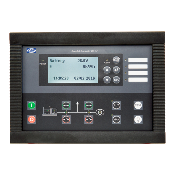
Контроллер GC-1F (Generator Controller – контроллер генераторного агрегата (ГА)) является микропроцессорным устройством, осуществляющим функции управления, контроля и защиты дизельного агрегата. Кроме этих функций блок содержит схемы для измерения 3-фазного тока и напряжения. Блок снабжен ЖК-дисплеем, на который выводятся значения параметров и аварийные сигналы. Для снижения энергопотребления дисплей контроллера управления генератором автоматически отключается через определенный промежуток времени и снова включается, при нажатии одной из кнопок или при изменении рабочих параметров. После включения питания GC-1F автоматически выполняет самодиагностику. В случае обнаружения неисправностей на дисплей выводится сообщение с номером неисправности, срабатывают реле звуковой сигнализации и реле состояния GC-1F.
Графический дисплей
• ЖК-дисплей STN, размеры 128 x 64 пикселей, с подсветкой;
• Вывод текстовых сообщений о неисправностях с помощью графических символов;
• Вывод текстовых диагностических сообщений, как по монтажным входам, так и по входам через шину CAN (разъем J1939);
• Журнал событий, хранящий до 30 сообщений;
• Часы реального времени с датой и временем суток;
Опции
Базовый блок контроллера генератора GC-1F может быть оснащен опцией AMF B3 (автоматического пуска при исчезновении/неисправности сетевого напряжения), необходимой для создания систем аварийного энергоснабжения. Кроме того, GC-1F поддерживает протокол CAN J1939 предназначенный для связи с двигателями, оборудованными собственными контроллерами с поддержкой данного протокола. Список всех возможных опций приведен в технической спецификации блока.
Настройка контроллера
Настройка GC-1F может производиться как посредством меню выводимого на его дисплей, так и с помощью компьютера, на котором установлено специальное программное обеспечение (ПО). ПО позволяет контролировать работу генераторной установки, а также управлять ею. Контроллер поддерживает как прямое подключение к компьютеру (интерфейса RS232), так и подключение с помощью модема. Параметры GC-1F закрыты от несанкционированного доступа с помощью пароля.
Стандартные функции
Управление двигателем
• Подготовка к пуску (подогреватель или предпусковая смазка);
• Конфигурируемый пуск/останов с числом попыток пуска, которое выбирается пользователем;
• Выбор электромагнитного клапана подачи топлива;
• Обеспечение режима холостого хода;
• Выбор схемы локального или дистанционного пуска/останова;
• Последовательность отключения с периодом охлаждения;
• Способ обнаружения запуска генераторного агрегата (выбирается пользователем):
— Вход переменного тока зарядного генератора (зажим W);
— Дискретный вход (клемма D+ зарядного генератора);
— Частота генератора;
— Давление масла;
• Счетчик времени наработки ГА и задание периодов ТО.
Контроль работы двигателя
• 3 многофункциональных входа: входы VDO, или 4-20 мА от активного датчика, или дискретные входы с функцией контроля состояния кабелей;
• 6 конфигурируемых дискретных входов;
• По выбору, вход таходатчика:
— Магнитный измерительный преобразователь;
— Измерительный преобразователь на npn- или pnp-структуре;
— Тахогенератор;
— Генератор переменного тока зарядного устройства.
Контроль работы генератора
• Контроль параметров 3-х фазных или однофазных синхронных генераторов электростанций: напряжение /ток /частота /мощность /реактивная мощность/cosφ
Защита генератора (ANSI)
• Повышение/понижение напряжения;
• Повышение/понижение частоты;
• Перегрузка по току;
• Обратная мощность;
• Несимметрия напряжений на шинах;
• Контроль чередования фаз.
Дополнительные функции
• Контроль несимметрии напряжения;
• Контроль чередования фаз;
• Управление насосом топливозакачки с функцией контроля заполнения;
• Функция “Тест”(режим “Простой тест” и режим “Неисправность сети”);
• Включение генераторного выключателя по температуре охлаждающей жидкости;
• Внешний подогрев.