
For some reason whenever I enter «router rip» on global config mode, I get the error msg «IP routing not enabled» Why is this ?
Comments
-
post your config
does it contain»no ip routing»?
-
enable password 654
!
no ip routing
!
interface Serial0
no ip address
no ip mroute-cache
no ip route-cache
shutdown
!
interface Serial1
no ip address
no ip mroute-cache
no ip route-cache
shutdownI have an IP + mask assigned to Serial0 though
-
 dmaftei
Member Posts: 83 ■■□□□□□□□□enable password 654
!
no ip routing <—- you don’t want this here…
!
… -
K, I went through setup and enabled RIP on the Serial0 interface. Here is the new config
!
interface Serial0
ip address 192.168.1.1 255.255.255.0
no ip mroute-cache
bandwidth 64000However, I’m still getting this:
Toes#show ip interface brief
Interface IP-Address OK? Method Status Protocol
Serial0 192.168.1.1 YES manual down downEh?
-
What’s it hooked to? Your layer one and layer two are down.
-
Interface IP-Address OK? Method Status Protocol
Serial0 192.168.1.1 YES manual down downSo if status is Down, and Protocol is Down, I suppose that means the cable is bad / not connected, and there is no routing protocol enabled on the interface ?
-
dmaftei
Member Posts: 83 ■■□□□□□□□□So if status is Down, and Protocol is Down, I suppose that means the cable is bad / not connected
That’s correct.
and there is no routing protocol enabled on the interface ?
No, protocol is down does not refer to a routing protocol.
-
What does ‘Protocol is down’ refer to ?
-
dmaftei
Member Posts: 83 ■■□□□□□□□□It refers to the line protocol. If you want to understand this stuff read about HDLC and PPP. If all you want is a live serial connection, your cable must be connected at both ends, and you must set the clock at one end; go to www.cisco.com and search for «HDLC back-to-back».
-
And the cable end connected to the router with the clockrate setting must be the DCE end.
-
Enabling ip routing is pretty simple, yet I am very concerned why my CCNA book did not mention ANYTHING about even checking to see if its enabled before they talk about rip, etc. I understand ip routing is enabled by default, but they never get into the fact incase someone disables it, and how to reenable ip routing, when the command is simply «(config)# ip routing» (!!!!)
I got my 1720 from ciscokits and they never cleared the previous config. I was messing around and came across the same issue. I googled it up and found out that to enable it I just typed «ip routing». As soon as I did this, router rip allowed me to configure rip routing.
CCNA Lab: Two 1720’s, one 2520, two 2924XL switches
[IPCop box] PIII 1GHz | 512MB RAM | 1 Gig Compact Flash HD
Errors in your CCNA text book? Never mind, the authors don’t care.
 dmaftei
 ![]()
Download Article
![]()
Download Article
Do you need to enable IP routing on a Cisco switch or router? By default, IP routing is disabled on most Cisco routers and switches. This can prevent devices on different VLANs from communicating with one another. In order for these devices to communicate with one another, the VLAN switches or routers need to have IP routing enabled and configured to route traffic between the two devices. This wikiHow teaches you how to use simple IOS commands to enable IP routing on your Cisco router or switch.
-
1
Connect your computer to the router or switch. If your router has a USB port, you can connect to your PC using a USB connection. If your router only has a Console port, you will most likely need a DB9-to-RJ45 cable. Connect the DB9 end of the cable to the Console port on your router. Then connect the female RJ45 end to a male RJ45 port on your computer. If your computer does not have a male RJ45 port, you can use a female RJ45-to-USB adapter.
- Alternatively, you can use a rollover cable (which is similar to an Ethernet cable, except the pins are reversed on the other end), and connect it to a female DB9-to-RJ45 adapter.
- Warning: Do NOT connect a rollover cable from the Ethernet port on your computer to the Console port on your router or switch. This will blow out the Console port on the router or switch.
-
2
Download a Terminal Emulation program (Windows only). If you are using a Mac or Linux computer, you already have a Terminal program built-in. If you are using a Windows PC, you need to download a terminal emulation program, such PuTTY.
Advertisement
-
3
Find the port number that your Cisco router or switch is connected to. If you are using a DB9-to-RJ45 cable, you will first need to install the drivers that came with the cable. Once you have your Cisco router or switch connected to your PC, use one of the following steps to find out the port number it is connected to:
- Windows: Right-click the Windows Start menu and click Device Manager. Expand «Ports (COM & LPT)» in the list of devices. Note the port number your router is connected to (i.e, «COM1»)
- Mac: Open the Terminal and type cd /dev and press Enter. Then type ls -ltr /dev/*usb* and press Enter. The port number will be listed after «/dev/tty.usbmodem» or » /dev/tty.usbserial».
-
Linux: Open the Terminal and type cd /dev and press Enter. Then type ls -ltr *ACM* and press Enter. The port number will be listed after «/dev/ttyUSB» or «/dev/ttyACM».[1]
-
4
Open a Terminal connection to the router or switch. Once you have the port number it is connected to, use one of the following steps to open a Terminal connection to your router or switch:[2]
-
Windows: Open PuTTY. Select Sessions in the Category menu to the left. Select Serial under «Connection type». Enter the port number the switch is connected to in the box labeled «Serial line.» Leave the speed as «9600». Then click Open.[3]
- Mac: Open the Terminal and type screen /dev/tty.usbmodem[port number] 9600 and press Enter. Replace «[port number]» with the port number you retrieved from the previous step.
- Linux: Open the Terminal and type screen /dev/ttyACM[port number] 9600 and press Enter. Replace «[port number]» with the port number you retrieved from the previous step.
-
Windows: Open PuTTY. Select Sessions in the Category menu to the left. Select Serial under «Connection type». Enter the port number the switch is connected to in the box labeled «Serial line.» Leave the speed as «9600». Then click Open.[3]


Advertisement
-
1
Connect to your router or switch. If you haven’t already done so, connect your router or switch to your computer. Then open a PuTTY or Terminal connection to your router or switch.
-
2
Type enable and press ↵ Enter. This enables EXEC mode. You may be asked to enter a password, if one is set.
-
3
Type configure terminal and press ↵ Enter. This enters Global Configuration mode.
-
4
Type ip routing and press ↵ Enter. This enables IP routing on your router or switch.
- If you want to exit Global Configuration mode, type end and press Enter.


Advertisement
-
1
Understand what Switch Virtual Interfaces are. A single router or switch can host multiple networks called «VLANs» Devices on a VLAN can communicate with each other without the user or a router or switch. However, each VLAN must have a Switch Virtual Interface in order for devices from different VLANs to communicate with each other.[4]
-
2
Enter Global Configuration mode. To enter Global Configuration mode, open a Terminal or PuTTY connection to the switch or router, and type «enable» and press «Enter.» Then type «configure terminal» and press «enter».
-
3
Type interface vlan followed by the VLAN ID and press ↵ Enter. This specifies the VLAN you want to configure. For example, if you wanted to configure VLAN1, you would type interface vlan 1 and press Enter.
-
4
Type ip address followed by the IP address and subnet mask of the network. An example command would be ip address 10.0.0.1 255.255.255.0 This assigns an IP address and subnet mask to the VLAN
-
5
Type end and press ↵ Enter. This exits the VLAN configuration mode and returns you to Global Configuration mode.
- If you want to view statistics for all the VLAN interfaces on your router or switch, type show interfaces vlan [vlan id] and press enter Replace [vlan id] with the actual VLAN ID number.


Advertisement
-
1
Understand what default routes and networks are. When a router receives a packet of information, it checks the destination address to route that information to the proper address. If a packet of information does not have a destination address, you can assign a default address and network to send all packets that do not have a destination address.[5]
-
2
Enter Global Configuraion mode. If you have not already done so, connect to your router or switch using PuTTY or the Terminal. Then type enable and press Enter to enter Exec mode. Then type configure terminal and press Enter to enter Global Configuration mode.
-
3
Type ip route followed by the default IP address and press ↵ Enter. This assigns the default route and network. An example of a default network could be «0.0.0.0 0.0.0.0» To set this as the default network, you would type, ip route 0.0.0.0 0.0.0.0.[6]


Advertisement
Ask a Question
200 characters left
Include your email address to get a message when this question is answered.
Submit
Advertisement
Thanks for submitting a tip for review!
References
About This Article
Thanks to all authors for creating a page that has been read 15,636 times.
Is this article up to date?
Обновлено 16.06.2016

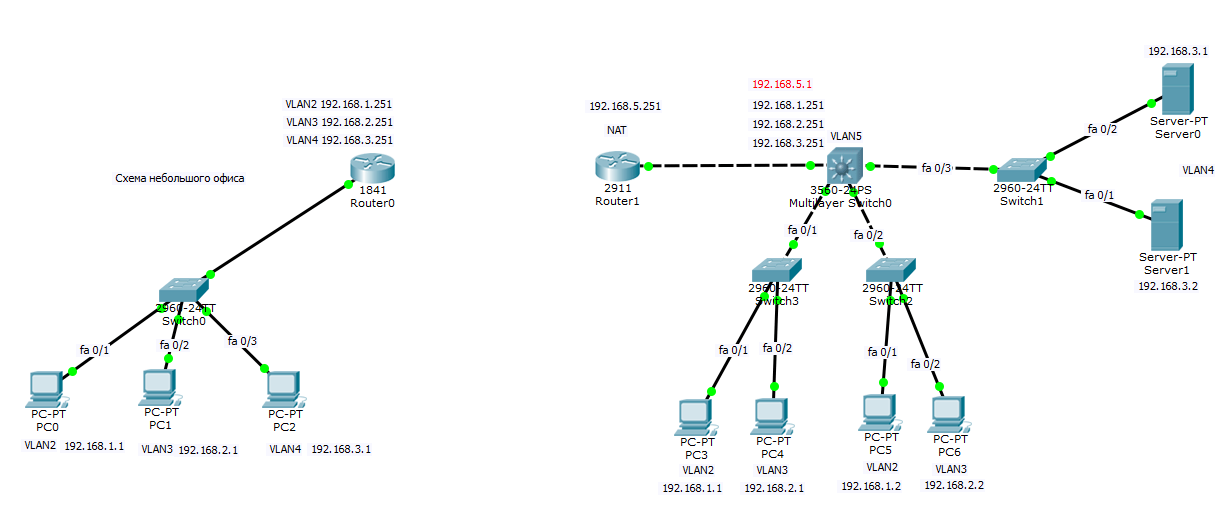
Всем привет сегодня мы с вами поговорим про такую вещь как статическая маршрутизация в оборудовании Cisco. Эта статья продолжение поста Как настроить маршрутизатор cisco / Организация сети для небольшого офиса. Там мы настроили локальную сеть в двух офисах компании, один маленький офис, второй чуть побольше. На роутере во втором офисе мы остановились на настройке статической маршрутизации, чем мы и займемся.
Таблица маршрутизации
Первое с чем нужно познакомиться, это с понятием таблицы маршрутизации. Если в двух словах это некая карта маршрутов, до сетей о которых знает ваш коммутатор 3 уровня или роутер. Для большей наглядности ее можно сравнить с картой дорог до городов России. И для того, чтобы например мне попасть из Москвы в Нижний Новгород, я должен выбрать определенную дорогу. Так и ваш роутер выбирает ее. Далее если мне нужно из Москвы попасть в Казань, и мне нужно ехать туда через Нижний Новгород, то В НН должен быть свой маршрут до Казани и так далее.

Статический маршрут — это постоянный неизменный маршрут, чаще всего прописанный в ручную.
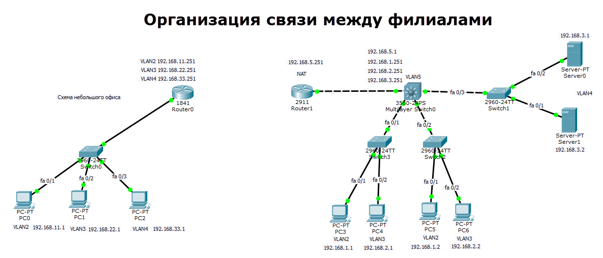
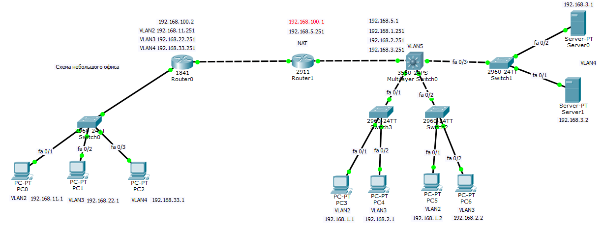
Схема сети офисов
У нас есть филиал, в котором 3 компьютера коммутатор второго уровня Cisco 2960 и Роутер Cisco 1841, есть три vlan (2,3,4). Есть главный офис в котором есть 5 vlan (2,3,4,5), маршрутизацией локального трафика занимается ядро в виде коммутатора 3 уровня Cisco 3560, который VLAN 5 подключен к роутеру Cisco 2911, на котором настроен будет интернет и канал до филиала.
В предыдущем посте где мы создавали данную локальную сеть я не настроил vlan 5 на роутере и ядре, исправим это.
Настройка Cisco 2911 и Cisco 3560
Настройка Cisco 3560
enable
conf t
Создаем Vlan 5
vlan 5
name VLAN5
exit
Настроим ip адрес VLAN5
int vlan 5
ip address 192.168.5.1 255.255.255.0
exit
Добавим порт gi1/1 в VLAN5
int gi0/1
выставляем режим доступа
switchport mode access
switchport access vlan 5
no shutdown
do wr mem
Настройка Cisco 2911
Так как у нас локальной маршрутизацией трафика занимается ядро то тут sub интерфейсов создавать не нужно. Настроим порт роутера gi0/0 на vlan5.
enable
conf t
Настроим ip адрес VLAN5
int gi0/0
ip address 192.168.5.251 255.255.255.0
no shutdown
do wr mem
Добавление статических маршрутов на Cisco 2911
Так как наш роутер Cisco 2911 ничего не знает о сетях 192.168.1.0, 192.168.2.0, 192.168.3.0, то нужно задать ему статические маршруты до них, через ядро делается это следующим образом.
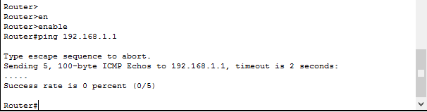
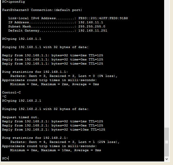
Удостоверимся что пинг не проходит до компьютера 192.168.1.1, вводим на роутере.
Видим ответов нет
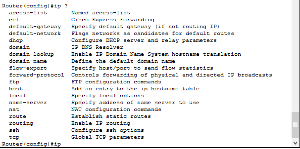
Переходим в режим конфигурирования командой
и смотрим команду ip:
Router(config)#ip ?
access-list Named access-list
cef Cisco Express Forwarding
default-gateway Specify default gateway (if not routing IP)
default-network Flags networks as candidates for default routes
dhcp Configure DHCP server and relay parameters
domain IP DNS Resolver
domain-lookup Enable IP Domain Name System hostname translation
domain-name Define the default domain name
flow-export Specify host/port to send flow statistics
forward-protocol Controls forwarding of physical and directed IP broadcasts
ftp FTP configuration commands
host Add an entry to the ip hostname table
local Specify local options
name-server Specify address of name server to use
nat NAT configuration commands
route Establish static routes
routing Enable IP routing
ssh Configure ssh options
tcp Global TCP parameters
Нам нужна команда ip route.
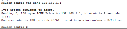
так как ip адрес на ядре сети (Cisco 3560) у VLAN 5 у нас 192.168.5.1 то он будет выступать для нас шлюзом. В итоге пишем.
ip route 192.168.1.0 255.255.255.0 192.168.5.1
ip route 192.168.2.0 255.255.255.0 192.168.5.1
ip route 192.168.3.0 255.255.255.0 192.168.5.1
и выполнив теперь команду Ping мы видим. что пакет дошел до 192.168.1.1
Планирование сети
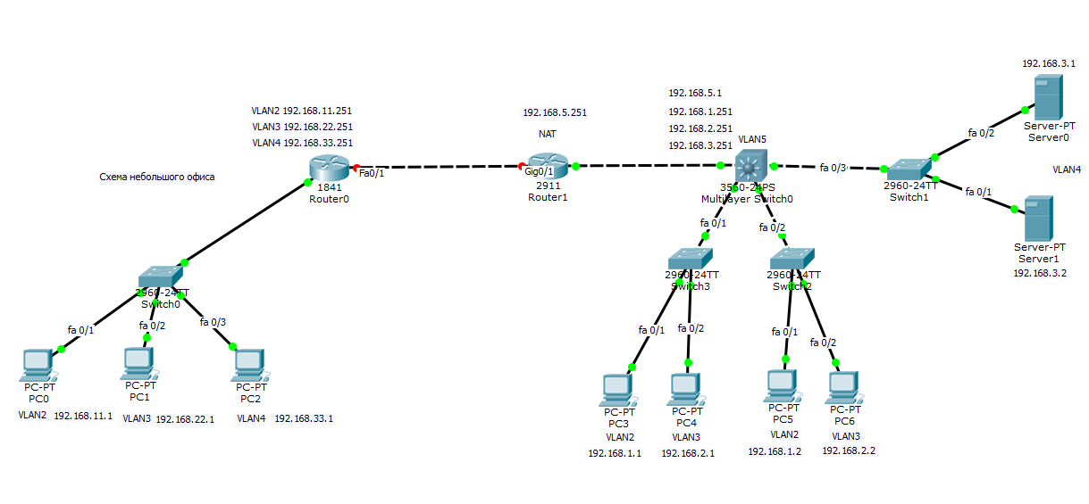
Все бы хорошо, но мы не правильно спланировали сеть в удаленном офисе. Так как там как и в главном, тоже есть сеть 192.168.1.0, 192.168.2.0, 192.168.3.0, такого быть не должно иначе получается дубли. Как правильно планировать сеть я писал тут, вам нужно перенастроить, как ранее описано в предыдущей статье. В итоге в филиале я заменил сети на 11, 22, 33 третьи актеты ip адреса. Общая картина теперь выглядит так.
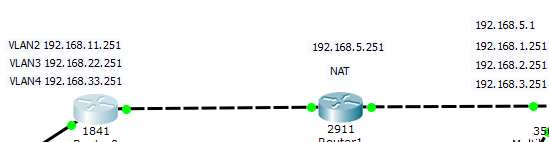
Соединение роутеров
Соединяем наши роутеры. Предположим, что между ними есть прямой линк, в жизни конечно это VPN канал. настроим в начале роутер Cisco 2911 в главном офисе.
маска тут 32 бита так как нам достаточно всего 2 ip адреса.
enable
conf t
int gi0/1
no shutdown
ip address 192.168.100.1 255.255.255.252
end
wr mem
Теперь настроим роутер Cisco 1841 в филиале. У меня это интерфейс fa0/1
enable
conf t
int fa0/1
ip address 192.168.100.2 255.255.255.252
no shutdown
do wr mem
У нас загорелись порты обоих коммутаторов.
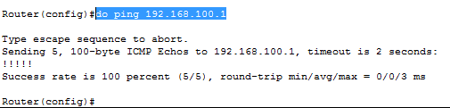
Проверяем пинги с роутеров друг до друга
Видим, что все успешно.
Настройка маршрутов между роутерами
Пробуем например с роутера в филиале пропинговать компьютер 192.168.1.1, и естественно пинг не пройдет так как нет маршрутов, чем мы и займемся. Так как у нас один шлюз соединения между офисами, то правильнее будет прописать один дефолтный путь, но можно и прописывать конкретный статический маршрут, например если основной шлюз интернет и весь трафик по умолчанию идет туда и вы хотите на конкретную сеть завернуть через другой шлюз.
ip route 0.0.0.0 0.0.0.0 192.168.100.1
но если бы нужно было прописать ручками каждый то вот так
ip route 192.168.1.0 255.255.255.0 192.168.100.1
ip route 192.168.2.0 255.255.255.0 192.168.100.1
ip route 192.168.3.0 255.255.255.0 192.168.100.1
do wr mem
Настроим теперь роутер у главного офиса, нам нужно добавить маршруты до сетей 192.168.11.0, 192.168.22.0, 192.168.33.0.
ip route 0.0.0.0 0.0.0.0 192.168.100.2
либо если нужно в ручную отдельным маршрутом.
ip route 192.168.11.0 255.255.255.0 192.168.100.2
ip route 192.168.22.0 255.255.255.0 192.168.100.2
ip route 192.168.33.0 255.255.255.0 192.168.100.2
do wr mem
Настройка маршрутов на ядре
Напомню, что локальный трафик маршрутизирует ядро сети коммутатор 3 уровня Cisco 3560, и на нем нужно тоже указать маршруты, до филиала. В качестве шлюза указывается, ip адрес vlan5 на роутере 2911 192.168.5.251
ip route 192.168.11.0 255.255.255.0 192.168.5.251
ip route 192.168.22.0 255.255.255.0 192.168.5.251
ip route 192.168.33.0 255.255.255.0 192.168.5.251
do wr mem
Вот финальный вид нашей филиальной сети.
Берем теперь компьютер из филиала с ip адресом 192.16811.1 и пробуем с него пропинговать 192.168.1.1 для примера. И видим, что все отлично пингуется, значит связь между офисами есть.
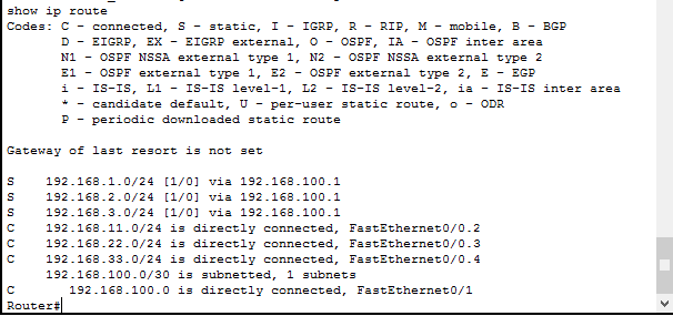
Посмотреть таблицу маршрутизации на Cisco можно командой
Где буква C означает что соединение установлено, буква S означает что маршрут статический.
Вот так вот просто объединить офисы в одну сеть, мы с вами разобрались со статической маршрутизацией, рассмотрели ее на примерах. В организации тестового стенда мне помог симулятор, Скачать Cisco packet tracer можно тут. На этом все.
Материал сайта pyatilistnik.org
Can someone help point me in the right direction. I’m trying to learn to configure this router for my home connection on my own. iOS 12.4 Cisco 2800 series router.
My client is pulling all the right info, IP, subnet mask, default gateway.
Initially I did not add a DNS server in there as I used import all to pull ISP config, but when that didn’t work I added the router as a DNS, then tried Google’s public.
I get a DNS_Probe error in chrome when attempting to browse.
However, I can’t ping an external address either.
Config is below.
Text
dot11 syslog
ip source-route
no ip routing
!
!
no ip cef
ip dhcp excluded-address 192.168.1.1
ip dhcp excluded-address 192.168.1.2
!
ip dhcp pool HOME
   import all
   network 192.168.0.0 255.255.0.0
   default-router 192.168.1.2
   dns-server 8.8.8.8
!
!
multilink bundle-name authenticated
!
!
!
!
!
!
!
!
!
!
!
!
!
!
!
!
!
!
!
voice-card 0
 no dspfarm
!
!
!
!
!
archive
 log config
  hidekeys
!
!
!
!
!
!
interface FastEthernet0/0
 ip address dhcp
 ip nat outside
 ip virtual-reassembly
 no ip route-cache
 duplex auto
 speed auto
!
interface FastEthernet0/1
 ip address 192.168.1.2 255.255.0.0
 ip nat inside
 ip virtual-reassembly
 no ip route-cache
 duplex full
 speed auto
 no mop enabled
!
ip forward-protocol nd
ip route 0.0.0.0 0.0.0.0 FastEthernet0/0
no ip http server
no ip http secure-server
!
!
ip nat inside source list 101 interface FastEthernet0/0 overload
!
access-list 101 permit ip 192.168.0.0 0.0.255.255 any
!
!
!
control-plane
!
!
!
!
!
!
!
!
!
line con 0
line aux 0
line vty 0 4
Switch#show license feature
Feature name Enforcement Evaluation Clear Allowed Enabled
ipservices yes yes yes no
ipbase yes no yes no
lanbase no no yes yes
Switch#show license fi
Switch#show license file
License Store: Primary License Storage
Store Index: 0
License: 11 lanbase 1.0 LONG NORMAL STANDALONE EXCL INFINITE_KEYS INFINITE
_KEYS NEVER NEVER NiL SLM_CODE CL_ND_LCK NiL *1X6KDW5XHCP25F4400
NiL NiL NiL 5_MINS <UDI><PID>WS-C3560X-24T-L</PID><SN>FDO1747P2KU
</SN></UDI> yJaPWRPQ1VO4nM68DvXf3PgXtM5J,Wk8T,ypXAkAgO3wwqySvIdkR
F0sAUvWAuX4VOoRR,9Y5ax7sSkt16juooLTJBHEcS0sjRTIxvDvv3d0Voozm1qyND
UE8fC4tkVtwcLB$<WLC>AQEBIf8B///7du8IK82WwtcpEEPO798jh93KySr3Egsmr
8SrfejHrR/de6mv2/kPeX0cSRwA+4ZHebPkGlARtYd1UQO7GJ3KnufZ9oZ6JdFniD
f5HrQ8DrXdpCz5RgZE+y8fbN200xiXA5cB3fwcJqoPIFZm2HmD1qFfsyTAzuio66t
6Xk5y8xo1lbVhvoh/FZfy5iRY3oE=</WLC>
Comment:
Hash: 8iRht3eRX9HGEpt7lbpv6YMv66w=
License Store: Evaluation License Storage
Store Index: 0
License: 11 ipservices 1.0 LONG TRIAL DISABLED 1440 DISABLED STANDALONE AD
D INFINITE_KEYS INFINITE_KEYS NEVER NEVER NiL SLM_CODE DEMO NiL N
iL Ni NiL NiL 5_MINS NiL CAORxVRms0Pgk9GAaXYO3UJxU1ygYKTzvmj21bkR
uc3R31Lqkj8kRdeCUAqUaMZcVZ$<WLC>AQEBIQAB//+ieoScBwE/AiB2ai9+tZznU
wNydhE5UCxJOb7Jny9vusIN27slWgVytw5m7vdezm+RqwInXo3s+nsLU7rOtdOxoI
xYZAo3LYmUJ+MFzsqlhKoJVlPyEvQ8H21MNUjVbhoN0gyIWsyiJaM8AQIkVBQFzhr
10GYolVzdzfJfEPQIx6tZ++/Vtc/q3SF/5Ko8XCY=</WLC>
Comment:
Hash: LInf2cvlrUoapigLGVfAyQcdBlo=
Добавлено через 2 минуты
Switch(config)#license boot level ipservices
PLEASE READ THE FOLLOWING TERMS CAREFULLY. INSTALLING THE LICENSE OR
LICENSE KEY PROVIDED FOR ANY CISCO PRODUCT FEATURE OR USING SUCH
PRODUCT FEATURE CONSTITUTES YOUR FULL ACCEPTANCE OF THE FOLLOWING
TERMS. YOU MUST NOT PROCEED FURTHER IF YOU ARE NOT WILLING TO BE BOUND
BY ALL THE TERMS SET FORTH HEREIN.
You hereby acknowledge and agree that the product feature license
is terminable and that the product feature enabled by such license
may be shut down or terminated by Cisco after expiration of the
applicable term of the license (e.g., 30-day trial period). Cisco
reserves the right to terminate or shut down any such product feature
electronically or by any other means available. While alerts or such
messages may be provided, it is your sole responsibility to monitor
your terminable usage of any product feature enabled by the license
and to ensure that your systems and networks are prepared for the shut
down of the product feature. You acknowledge and agree that Cisco will
not have any liability whatsoever for any damages, including, but not
limited to, direct, indirect, special, or consequential damages related
to any product feature being shutdown or terminated. By clicking the
«accept» button or typing «yes» you are indicating you have read and
agree to be bound by all the terms provided herein.
ACCEPT? (yes/[no]):