
Японская компания Kyocera производит высококачественные лазерные принтеры и МФУ для офисной печати. Их продукция одна из самых востребованных на сегодняшний день. Ведь печатающие устройства Kyocera характеризуются высокой надежностью, износостойкостью и большим сроком эксплуатации. Однако даже их изделия не являются вечными. Со временем принтеры Kyocera начинают сбоить.
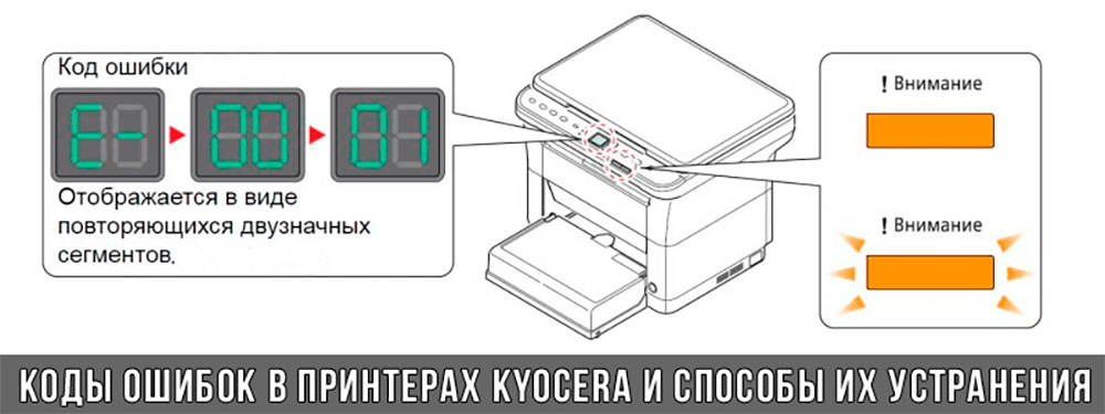
К счастью, оргтехника Kyocera оснащена системой самодиагностики (так же, как и струйные принтеры Canon). Поэтому, в случае возникновения проблемы, устройство самостоятельно выявит уязвимое место и сообщит Вам об этом миганием соответствующего индикатора на панели управления либо кодом ошибки, выведенным на дисплей принтера.
Если Вы не являетесь мастером по обслуживанию принтеров и МФУ Kyocera, то, чтобы понять, о чем сообщает печатающее устройство, Вам потребуется расшифровать указанный им код. Для этого мы добавили в статью таблицу кодов ошибок лазерных принтеров Kyocera серии FS и не только.
Коды ошибок принтеров и МФУ Kyocera, которые можно исправить самостоятельно
|
Код ошибки |
Значение ошибки |
Решение проблемы |
|
E-0001 (E1) |
Поврежден чип картриджа либо установлен неоригинальный картридж. |
Замените установленный картридж оригинальной версией изделия. Если хотите сэкономить, тогда купите и установите новый чип на картридж или перепрошейте принтер Kyocera. Однако предварительно не помешает попробовать сбросить ошибку соответствующей комбинацией клавиш (как это сделать, читайте в статье «Сброс ошибки установки неоригинального картриджа в принтерах Kyocera»). |
|
E-0002 (E2) |
Регион использования картриджа и принтера не совпадают. |
Замените чип или прошейте принтер Kyocera. |
|
E-0003 (E3) |
Заполнена память принтера или МФУ Kyocera. |
Отпечатайте ранее отсканированные листы или очистите очередь печати нажатием кнопки Стоп/Сброс (ранее отсканированные листы также удалятся из памяти принтера, даже если они еще не были распечатаны). |
|
E-0007 (E7) |
Тонер-картридж Kyocera израсходовал ресурс красящего вещества. |
Замените или заправьте картридж Kyocera (если используете совместимый или перезаправленный расходник, то после установки его в принтер не забудьте сбросить ошибку зажатием на 3-5 секунды кнопок [Ок] и [Сброс/Стоп]). |
|
E-0008 (E8) |
Открыта крышка принтера либо не работает датчик закрытия крышек устройства. |
Откройте и еще раз закройте переднюю и заднюю крышку принтера. Во время закрытия Вы должны услышать характерный щелчок. Если не помогло, то причина в неисправности датчика. |
|
E-0009 (E9) |
Лоток приема бумаги полон. |
Уберите все отпечатанные листы бумаги из выходящего лотка. Чтобы возобновить печать, нажмите кнопку [Старт]. |
|
E-0012 (E12) |
Ошибка памяти принтера Kyocera. |
Попробуйте уменьшить разрешение печати. Скорее всего, формат создаваемого отпечатка не соответствует возможностям принтера. |
|
E-0014 (E14) |
Установлен неверный формат бумаги (неподдерживаемый принтером Kyocera). |
Поменяйте бумагу на поддерживаемую принтером либо смените ее формат в настройках печати. Попробуйте обновить программное обеспечение. Возможно, это расширит поддерживаемые принтером Kyocera форматы. |
|
E-0015 (E15) |
Устройство не подключено к электрической сети либо на компьютере нет (не работает) драйвера принтера Kyocera. |
Проверьте подключение печатающего аппарата к электрической сети, а также целостность кабеля. Если ошибка не исчезает, скачайте драйвер принтера Kyocera и установите его на компьютер. |
|
E-0017 (E17) |
Ошибка передачи данных. |
Проверьте подключение принтера к компьютеру. Кабель не должен быть длиннее 5 метров, а также обязан поддерживать стандарт USB 2.0. Кроме того, переустановите драйвер принтера и утилиту Kyocera Client Tool. |
|
E-0018 (E18) |
Очередь печати заполнена. |
Очистите очередь печати нажатием кнопки [Сброс] либо через драйвер принтера. |
|
E-0019 (E19) |
Неверный формат печати. |
Отмените печать нажатием кнопки [Стоп/Сброс]. Выберите в настройках принтера соответствующий режим печати, а также установите в лоток поддерживаемый принтером формат бумаги. |
|
J-0000 (jam0000) |
Замятие бумаги за задней крышкой. |
Откройте крышку и извлеките бумагу. Проверьте надежность крепления бумаги в лотке, а также принтер на наличие посторонних предметов. Еще причина может быть в пружине выходного флажка. Если она растянулась, то может плохо работать фиксатор. Также проблема может быть из-за печки, сделайте ее ревизию, переборку и смазку. |
|
J-0501 (jam0501) |
Бумага застряла в принтере Kyocera |
Извлеките замятую бумагу. Проверьте надежность установки бумаги во входной лоток. Проверьте целостность роликов протяжки бумаги, а также принтер на наличие посторонних предметов. Если не помогло, стоит внимательно осмотреть ребра на направляющей пластине. На них могут образоваться сколы, трещины и заусенцы. Их можно слегка подчистить наждачной бумагой (нулевкой). |
|
J-0511 (jam0511) |
Принтер Kyocera замял бумагу. |
Извлеките замятую бумагу и повторите печать. Если проблема не исчезла, несите принтер в сервис. Скорее всего, изношен ролик протяжки бумаги. |
|
C7990 |
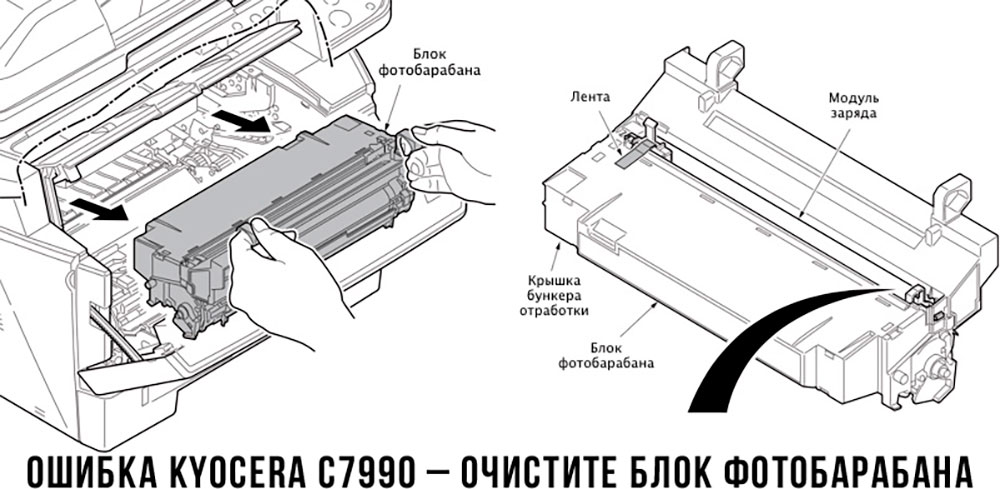
Бункер драм-картриджа (блока фотобарабана) заполнен отработанным тонером либо неисправен счетчик отработки красящего вещества. Еще проблема может быть в главной плате PWB. |
Осуществите чистку драм-картриджа (блока фотобарабана). Если проблема в датчике или плате, то нужно отнести принтер в СЦ на диагностику. |
|
F248 |
Ошибка обработки отпечатываемого материала. |
Перезагрузите принтер. Уберите неподдерживаемые спецсимволы из отпечатка. Обновите ПО принтера Kyocera. Смените режим работы принтера с PDL на GDI (Пуск -> Принтеры -> Свойства -> Параметры устройства). |
|
PF |
Отсутствует бумага в лотке подачи. |
Загрузите листы бумаги во входной лоток. Если принтер по-прежнему не печатает, значит нужно искать проблему в чем-то другом. |
|
1101 |
Ошибка сканирования через сеть из-за неправильного имени SMTP сервера. |
Пропишите DNS-адреса помимо прочих настроек печати по сети. |
|
1102 |
Некорректная настройка сканера для работы через сеть |
Зайдите в Web-панель управления принтером (нужно в адресную строку браузера ввести iP принтера Kyocera). Далее в зависимости от модели введите логин и пароль (Admin/Admin или просто admin00 без логина). Далее следуйте инструкции:
Логин и пароль нужны обязательно, если их нет, то следует создать. |
|
2101 |
Ошибка передачи данных при сканировании через сеть. |
Правильно настройте параметры (как для ошибки 1102), только предварительно отключите на ПК антивирус и брандмауэр. |
Если Вы испытали все способы, но не смогли убрать ошибку, то следует нести печатающее устройство в сервисный центр. Кроме того, есть ряд ошибок (высвечиваемых на дисплее принтера), которые нельзя устранить в домашних условиях. Соответствующие коды ошибок принтеров Kyocera представляем в очередной таблице.
Коды ошибок принтеров и МФУ Kyocera, которые нужно устранять в сервисном центре
|
Код ошибки |
Значение ошибки |
Решение проблемы |
|
0030 |
Неисправность платы управления факсом принтера. |
Замена платы. |
|
0100 |
Неисправность платы управления или флеш-памяти принтера. |
Замена платы. |
|
0120 |
Ошибка чтения mac-адреса из-за неисправности флеш-памяти принтера. |
Замена платы. |
|
0190 |
Неисправность платы управления или флеш-памяти принтера. |
Замена платы. |
|
0630 |
Неисправность платы управления принтера. |
Замена платы. |
|
1020 |
Неисправность мотора, привода или отсутствие контакта. |
Разборка принтера и замена изношенных частей. Проверка надежности подключений, замена разорванных (прогоревших) кабелей. Ремонт или замена привода мотора. |
|
1040 |
Неисправность мотора, привода или отсутствие контакта. |
Разборка принтера и замена изношенных частей. Проверка надежности подключений, замена разорванных (прогоревших) кабелей. Ремонт или замена привода мотора. |
|
2000 |
Неисправность главной платы управления, соединительного кабеля или привода принтера. |
Проверить ремни, шестерни и ролики привода. Смазать или заменить, если есть дефекты. Заменить привод или главную плату. |
|
3100 (C3100) |
Неисправность главной платы, привода сканера, датчика положения или нарушение целостности соединений. |
Проверить наличие разрывов и отсутствия контакта. Смазать или заменить изношенные элементы привода. Заменить привод, главную плату, датчик или соединительный кабель. Если Вам повезло, то возможно забыли отключить фиксатор блока сканера. |
|
3101 |
Сетевой кабель не подсоединен, или нарушена работа концентратора. Еще может быть из-за наличия вирусов в системе или неправильно заданным параметрам сервера SMTP. |
Проверить соединения, правильно настроить параметры сети. |
|
3300 |
Неисправность главной платы, датчика CIS или соединительного кабеля. |
Проверить контакты, заменить плату или датчик. |
|
3500 |
Неисправность главной платы или нарушение соединения контактов. |
Проверить контакты, заменить плату. |
|
4000 (C4000) |
Неисправность главной платы, привода сканера или нарушение соединений. Однако чаще всего ошибка лазера. |
Проверить контакты, заменить плату или привод блока сканера. Почистить лазер, смазать ось полигон-мотора, либо полностью заменить блок лазера. |
|
4200 |
Неисправность главной платы, блока сканера или датчика BD. |
Отключить питание принтера на 30 минут. Если не помогло, то следует заменить привод сканера или главную плату принтера. |
|
6000 (С6000) |
Неисправность главной платы, термостата, печки или нарушение соединения контактов. |
Проверить и поправить контакты. Заменить фьюзер. Ремонт или замена печки, термодатчика, термопредохранителя и т.д. |
|
6020 |
Сгорание термистора или главной платы. |
Замена термистора или главной платы. |
|
6030 |
Неисправность главной платы, термостата или термистора. Возможно, причина в отсутствии контакта. |
Проверить соединения. Заменить плату, термостат или термистор. |
|
6400 |
Неисправность главной платы, отсутствие питания или контакта. |
Заменить плату или источник питания. |
|
F000 |
Неисправность главной платы или отсутствие контакта. |
Проверить соединение ремня безопасности. Заменить ремень или плату управления. |
|
F020 |
Неисправность элементов памяти принтера. |
Перезагрузить принтер. Если ошибка не устранилась – заменить плату управления. |
|
F040 |
Неисправность главной платы принтера. |
Перезагрузить принтер. Если ошибка не устранилась – заменить плату управления. |
|
F05D |
Неисправность главной платы. Сбой программного оборудования привода. Проблемы с прошивкой принтера Kyocera. |
Перезагрузить принтер. Если ошибка не устранилась – заменить плату управления. Перепрошить принтер Kyocera. |
|
F245 F246 F247 F375 |
Принтер Kyocera заблокирован из-за проблемы, вызванной отказом источника питания. |
Нужно перепрошить принтер специальной сервисной микропрограммой. |
Обратите внимание: Если у печатающего устройства нет дисплея, то определить проблему можно по светодиодным индикаторам, встроенным в панель управления принтером. Например, у Kyocera Ecosys P2135D нужно сосчитать количество миганий индикаторов красного цвета и таким образом определить число, указывающее на ту или иную ошибку. В свою очередь, у модели Kyocera FS-1040 все зависит от темпа мигания светодиода с надписью «Внимание!» («Attention!»):
- Мигает медленно – указывает на отсутствие бумаги в лотке или тонера в картридже.
- Мигает быстро – оповещает о проблеме с памятью устройства, переполненном лотке или замятии бумаги, а также об использовании неоригинальных расходных материалов.
- Горит постоянно – говорит о проблемах с картриджем или фотобарабаном либо указывает на открытые крышки принтера.
Чтобы потребитель мог наверняка определить проблему, рекомендуем использовать утилиту Kyocera Client Tool, которая идет в комплекте с драйверами принтера.
Ваше Имя:
Ваш вопрос:
Внимание: HTML не поддерживается! Используйте обычный текст.
Оценка:
Плохо
Хорошо
Введите код, указанный на картинке:


Ошибка C6030 Kyocera ECOSYS M2035dn – сбой в работе термистора узла термозакрепления.
Закрепление тонера на бумаги происходит за счет давления и температуры. Рабочая температура узла термозакрепления 170-180 градусов. Температура создается нагревательной лампой, установленной внутри тефлонового вала, и поддерживается термистором — датчиком температуры. Вероятная причина ошибки C6030 – неисправен термистор, отклонение положения установки термистора, нет соединения термистора с платой управления.
Мы выполняем ремонт Kyocera ECOSYS M2035dn для устранения ошибки C6030.
Цены на услуги ремонт МФУ в нашей компании.
Ремонт принтеров Kyocera в нашей компании — качество, надёжность и оперативность.
Мы 20 лет успешно работаем на рынке ремонта офисной техники в Москве.
Наша компания работает с физическими и юридическими лицами, и принимает любые способы оплаты. Вам нужно просто позвонить по телефону и задать свои вопросы нашему инженеру по ремонту принтеров. Мы уделяем максимальное внимание каждому клиенту. Выезд инженера для ремонта по Москве. Любая форма оплаты.
Срочный ремонт офисной техники Kyocera в Москве в районе метро Серпуховская.
Стоимость
Ремонт принтеров
| Вид устройства и формат печати | Монохромные формата А4 | Монохромные формата А3 | Цветной формата А4 | Цветной формата А3 |
| Диагностика | бесплатно | бесплатно | 300 | 300 |
| Мелкий ремонт | 500 | 500 | 500 | 800 |
| Средний ремонт | 1000 | 1000 | 1500 | 1500 |
| Сложный Ремонт |
1500 | 1500 | 2000 | 2500 |
| Профилактика принтера | 1000 | 1200 | 1500 | 2000 |
Ремонт МФУ
| Вид устройства и формат печати | Монохромные МФУ формата A4 |
Монохромные МФУ формата A3 |
Цветной МФУ формата A4 |
Цветной МФУ формата A3 |
| Диагностика МФУ |
Бесплатно | Бесплатно | 400 руб. | 600 руб. |
| Мелкий ремонт МФУ | 600 руб. | 800 руб. | 500 руб. | 800 руб. |
| Средний ремонт МФУ | 1000 руб. | 1500 руб. | 1500 руб. | 1500 руб. |
| Сложный ремонт МФУ |
1500 руб. | 2000 руб. | 2000 руб. | 2500 руб. |
| Профилактика МФУ | 1200 руб. | 1500 руб. | 1500 руб. | 2000 руб. |
Ремонт копировальных аппаратов
| Тип копировального аппарата | Диагностика копировального аппарата в нашем сервисном центре |
Диагностика копировального аппарата на выезде у заказчика | Ремонт копировального аппарата в нашем сервисном центре |
Ремонт копировального аппарата на выезде у заказчика |
| Копировальные аппараты формата А4 до 20 коп./мин. | 400 | 1000 | 1000 | 2500 |
| Копировальные аппараты формата А4 свыше 20 коп./мин. | 400 | 1000 | 1000 | 2500 |
| Копировальные аппараты формата А3 до 20 коп./мин. | 400 | 1000 | 1500 | 2500 |
| Копировальные аппараты формата А3 свыше 20 коп./мин. | 400 | 1000 | 1500 | 2500 |
| Копировальные аппараты формата А3 свыше 40 коп./мин. |
400 | 1000 | 2000 | 3500 |
| Цветные копировальные аппараты | 600 | 1500 | 2000 | 3500 |
| Инженерные машины А0 | 800 | 2000 | 4000 | 6000 |
Заправка картриджей HP
| № картриджа | модель аппарата | цена заправки | цена восстановлени |
| Q2612A | 1010/1015/1018/ 1020/1022/3015/3030/ 3050/3055/M1005 |
500 | 1000 |
| C4092A | 1100 / 3200/3220 | 500 | 1100 |
| C7115A | 1000 / 1005/1200/3380 | 500 | 1000 |
| C7115X | 1000 / 1005/1200/3380 | 700 | 1200 |
| Q2613A | 1300 | 500 | 1000 |
| Q2613X | 1300 | 700 | 1200 |
| Q2624A | 1150 | 500 | 1000 |
| Q5949A | 1160 / 1320 | 500 | 1000 |
| Q5949X | 1320 | 700 | 1200 |
| Q7553A | P2015/M2727 | 500 | 1000 |
| Q7553X | P2015/M2727 | 700 | 1200 |
| C4096A | 2100 / 2200 | 600 | 1200 |
| Q2610A | 2300 | 800 | 1300 |
| Q6511A | 2410 /2420/2430 | 800 | 1400 |
| Q6511X | 2410/2420/2430 | 1100 | 1700 |
| Q7551A+ЧИП | P3005 | 800 | 1400 |
| Q7551X+ЧИП | P3005 | 1200 | 1800 |
| C4127X | 4000 /4050 | 1000 | 1600 |
| C8061A | 4100 | 800 | 1400 |
| Q1338A | 4200 | 1500 | 2100 |
| Q1339A | 4300 | 1500 | 2100 |
| Q5942A | 4250 /4350 | 1000 | 1600 |
| C4129X | 5000 /5100 | 1300 | 2000 |
| Q7516A+ЧИП | 5200 | 1100 | 1800 |
| Q7570A+ЧИП | M5025/M5035 | 1100 | 1800 |
| CF214A | LaserJet Enterprise 700 Printer M712dn, M712xh | 1100 | 1800 |
| CF214X | LaserJet Enterprise 700 Printer M712dn, M712xh | 1500 | 2200 |
| C3909A | 5Si/8000 | 1100 | 1800 |
| C4182X | 8100 | 1300 | 2000 |
| C8543X | 9000/9040/9050 | 1900 | 2600 |
| CE 278A | P1566/1606 | 500 | 1000 |
| CE285A | P1102 | 500 | 1000 |
| CB435A | P1005/P1006 | 500 | 1000 |
| CB436A | P1505/M1120/M1522 | 500 | 1000 |
| CE 505A | P2035/P2055 | 500 | 1000 |
| CE 505X | P2055 | 700 | 1200 |
| CE255A | P3015 | 600 | 1200 |
| CE255X | P3015 | 900 | 1500 |
| CC364A | P4014/P4015/P4515 | 1000 | 1700 |
| CC364X | P4015/P4515 | 1400 | 2100 |
| CE390A | Enterprise M4555/M601/M602/ M603 |
1000 | 1700 |
| CE390X | Enterprise M4555/M602/ M603 |
1400 | 2100 |
| CZ192A | Pro M435 | 1100 | 1800 |
Заправка картриджей Brother
| Модель принтера Brother | Картридж | ресурс | Цена, руб. |
| DCP 7010, 7010R, 7020, 7025, 7025R, FAX 2820, 2825, 2825R, 2920, 2920R, HL 2030, 2030R, 2040, 2040R, 2070, 2070N, 2070NR, MFC 7225, 7225N, 7420, 7420R, 7820, 7820N, 7820NR, 7820R | TN 2075 | 2000 | 600 |
| DCP 8040, 8040LT, 8045, 8045D, 8045DN, HL 5130, 5140, 5140LT, 5150, 5150D, 5150DLT, 5170, 5170DN, MFC 8040, 8045, 8045D, 8045DN, 8220, 8440, 8840, 8840D, 8840DN, 8840LT |
TN 3030 TN 3060 |
3500 6500 |
900 1200 |
| HL 2035, 2035R | TN 2085 | 1500 | 600 |
| DCP 7030, 7030R, 7032, 7032R, 7040, 7045, 7045NR, HL 2140, 2140R, 2142, 2142R, 2150, 2150N, 2150NR, 2170, 2170W, 2170WR, MFC 7320, 7320R, 7440, 7440N, 7440NR, 7840, 7840W, 7840WR |
TN 2135 TN 2175 |
1500 2000 |
600 |
| DCP 8060, 8065, 8065DN, HL 5200, 5240, 5250, 5250DN, 5270, 5270DN, 5280, 5280DW, MFC 8460, 8460N, 8860, 8860DN, 8860N, 8870, 8870DW |
TN 3130 TN 3170 |
3500 5000 |
900 1200 |
| HL2130R/DCP7055R | TN-2080 | 700 | 600 |
| Brother HL-1112R/DCP-1512R/HL-1110R/DCP-1510R/MFC-1810R/MFC-1815R (новинка) | TN-1075 | 1000 | 600 |
| HL-2240R/ 2240DR/ 2250DNR/ DCP-7060DR/ 7065DNR/ MFC-7360NR/ 7860DWR |
TN-2235 TN-2275 |
1200 2600 |
600 600 |
| HL-5340D/5350DN/5350DNLT/ 5370DW/5380DN для DCP-8070D/8085DN для MFC-8370DN/8380DN/8880DN/8890DW |
TN-3230 TN-3280 |
3000 8000 |
900 1200 |
Заправка картриджей Samsung
| Номер картриджа | Модель аппарата | Стоимость заправки | Стоимость восстановления |
| MLTD101S | ML-2160/2165/2168/ SCX-3400F/3405F/3407 1.5К (ЧИП) | 900 | 1400 |
| MLTD103S/L | ML-2950/2955/SCX-4728/4729 1,5/ 2,5 К (ЧИП) | 800 | 1200 |
| MLTD104S | ML1660/ 1665/SCX3200/ 3205 1,5 К (ЧИП) | 800 | 1200 |
| MLTD105L | ML1910/ 1915/ML2525/2580N/ SCX4600/4623F/SF-650 2,5 К (ЧИП) | 800 | 1200 |
| MLTD105S | ML1910/ ML2525/SCX4600 1,5 К (ЧИП) | 800 | 1200 |
| MLTD106S | ML2245 2K. (ЧИП) | 800 | 1200 |
| MLTD108S | ML1640/1645/2240/2241Black 1,5K (ЧИП) | 800 | 1200 |
| MLTD109S | SCX4300 2 К (ЧИП) | 900 | 1300 |
| MLTD111S | Xpress SL-M2020/SL-M2022/SL-M2022W/SL-M2070 1K (ЧИП) | 900 | 1500 |
| MLT-D115L | Xpress SL-M2620/SL-M2620D/SL-M2820/SL-M2820ND/SL-M2820DW 3K | 1200 | 1600 |
| MLTD117S | SCX-4650M/4655FN 2,5K (ЧИП) | 900 | 1400 |
| MLTD203E | M3820/3870/4020/4070 | 1500 | 1800 |
| MLTD205L | SCX4833/ML3310 5К (ЧИП) | 900 | 1300 |
| MLTD205S | SCX4833/ML3310 2К (ЧИП) | 800 | 1100 |
| MLTD209L | ML2855ND/ SCX4824FN/4828 5К (ЧИП) | 900 | 1300 |
| MLTD209S | ML2855ND/ SCX4824FN/4828 2К (ЧИП) | 800 | 1100 |
| ML1210D3 | ML1210/ ML1250/ML1430 2,5К | 500 | 800 |
| ML1520D3 | ML1520P/ ML1720 3K | 500 | 800 |
| ML1610D2 | ML1615 2K | 500 | 800 |
| MLD1630A | ML1630/ SCX4500 2K (ЧИП) | 700 | 1100 |
| ML1710D3 | ML1510/ ML1710/ML1750 3К | 500 | 1100 |
| ML2010D3 | ML2015/ ML2510/ML2570 3К (предохр.) | 600 | 1000 |
| ML2150D8 | ML2150/ ML2151N/ML2152W 8К (ЧИП) | 900 | 1300 |
| ML2250D5 | ML2250/ ML2251N/ML2252W 5К (ЧИП) | 800 | 1200 |
| ML2550DA | ML2550/ ML2551N/ML2552W 10К (ЧИП) | 1000 | 1300 |
| MLD2850A | ML2850D/ ML2851ND 2К (ЧИП) | 700 | 1100 |
| MLD3050A | ML3050/ ML3051N 4К (ЧИП) | 800 | 1200 |
| MLD3050B | ML3050/ ML3051N 8К (ЧИП) | 900 | 1300 |
| MLD3470A | ML3470D/ ML3471ND 4К (ЧИП) | 900 | 1300 |
| MLD3470B | ML3470/ 3471ND 10К (ЧИП) | 1000 | 1400 |
| ML3560D6 | ML3560/ ML3561N 6К (ЧИП) | 800 | 1200 |
| SCX4100D3 | SCX4100 3К | 500 | 800 |
| SCXD4200A | SCX4200 3K (ЧИП) | 600 | 1000 |
| ML4500D3 | ML4500 2,5К | 600 | 1000 |
| SCX4521D3 | SCX4321/ SCX4521F 3К (предохранитель) | 600 | 1000 |
| MLD4550A | ML4550/ ML4551N 10К (ЧИП) | 1000 | 1400 |
| MLD4550B | ML4550/ ML4551N 20К (ЧИП) | 1500 | 1900 |
| SCX4720D3 | SCX4720 3К (ЧИП) | 800 | 1200 |
| SCX4720D5 | SCX4720 5К (ЧИП) | 900 | 1300 |
| SCXD4725A | SCX4725F/SCX4725FN 3К (ЧИП) | 700 | 1100 |
| SF5100D3 | SF5100/ SF5100P 2,5К | 500 | 800 |
| SCX5312D6 | SCX5112/SCX5312F 6K (ЧИП) | 1200 | 1600 |
| SCXD5530A | SCX5330N/ SCX5530FN 4К (ЧИП) | 900 | 1300 |
| SCXD5530B | SCX5330N/ SCX5530FN 8К (ЧИП) | 1000 | 1400 |
| SCX6320D8 | SCX6122FN 8K (ЧИП) | 1200 | 1800 |
| ML6060D6 | ML1440/ ML6040/ML6060 6К (ЧИП) | 900 | 1300 |
| ML7300DA | ML7300N 10К (ЧИП) | 1500 | 1900 |
Заправка картриджей Xerox
| Модель принтера, ресурс | Номер картриджа | Цена заправки |
| Phaser 3010/3040/WC3045 (3К) | 106R02183 (ЧИП) | 600 |
| Phaser 3100 + смарт карта (3К) | 106R01378/106R011379(смарт-карта) | 900 |
| Phaser 3110/3210 (3К) | 109R00639 | 500 |
| Phaser 3116 (3К) | 109R00748 (предохр.) | 600 |
| Phaser 3117/3122/3124/3125 (3К) | 106R01159 (предохр.) | 600 |
| Phaser 3120/3121/3130 (3К) | 109R00725 | 500 |
| Phaser 3140/3155/3160 (2.5К) | 108R00908/108R00909(ЧИП) | 600 |
| Phaser 3150 (3.5/5К) | 109R00746/109R00747(ЧИП) | 700 |
| Phaser 3200 (2/3К) | 113R00735/113R00730 (ЧИП) | 600 |
| Phaser 3250 (3.5/5К) | 106R01373/106R01374 (ЧИП) | 700 |
| Phaser 3300 (8К) | 106К01411/106К01412(ЧИП) | 800 |
| Phaser 3310 (6К) | 106R00646 | 700 |
| Phaser 3400 (6/8К) | 106R00461/106R00462 | 700 |
| Phaser 3420/3425 (5/10К) | 106R01033/106R01034(ЧИП) | 900 |
| Phaser 3428 (4/8К) | 106R01245/106R01246 (ЧИП) | 800 |
| Phaser 3435 (5/10К) | 106R01414/106R01415 (ЧИП) | 900 |
| Phaser 3500 (6/12К) | 106R01148/106R01149 (ЧИП) | 1000 |
| Phaser 3550 (5К) | 106R01529 (ЧИП) | 800 |
| Phaser 3600 (7/14/20К) | 106R01370/106R01371/106R01372 | 1100 |
| Phaser3635 (10К) | 108R00794/108R00796(ЧИП) | 1000 |
| Phaser 4400 (10/15К) | 113R00627/113К00628 | 1000 |
| Phaser 4510 (10/19К) | 113R00711/113R00712 | 1000 |
| Phaser 5335 (10К) | 113R00737 | 1000 |
| Phaser 5400 (20К) | 113R00495 | 1300 |
| WC-312/M15 (6К) | 106R00586 | 800 |
| WC-3119 (3К) | 013R00625 (ЧИП) | 600 |
| WC3210/3220 (4.1К) | 106R01485/106R01487(ЧИП) | 700 |
| WC-4118 (8К) | 006R01278(ЧИП) | 800 |
| WC-M20 (8К) | 106R01048 (ЧИП) | 800 |
| WC-PE16 (3.5К) | 113R00667 (предохр.) | 600 |
| WC-PE114 (3К) | 013R00607 | 500 |
| WC-PE120 (3.5/5К) | 013R00601/013К00606 (ЧИП) | 700 |
| WC-PE220 (3К) | 013R00621 (ЧИП) | 700 |
| P8EX (5К) | 603P06174 (113R00296) | 700 |
Заправка картриджей Kyocera
| Тонер-картридж | МОДЕЛЬ АППАРАТА | РЕСУРС | ЦЕНА Заправки в сервисном центре руб. |
| TK-100 | KM-1500 | 6000 | 1 000 |
| TK-110 | FS-720 / 820 / 920 / 1016 | 6000 | 1 000 |
| TK-1100 | FS -1110 / 1024MFP / 1124MFP | 2100 | 700 |
| TK-110E | FS-720 / 820 / 920 / 1016 | 2000 | 700 |
| TK-1110 | FS -1040, FS-1020MFP / FS-1040MFP / FS-1120MFP | 2500 | 700 |
| TK-1120 | FS-1060 / FS-1025MFP / FS-1125MFP | 3000 | 750 |
| TK-1130 | FS -1030MFP / 1130MFP | 3000 | 750 |
| TK-1140 | FS -1035MFP / 1135MFP | 7200 | 1 100 |
| TK-120 | FS-1030D | 7200 | 1 100 |
| TK-130 | FS-1028 / 1128 / 1300 / 1350 | 7200 | 1 100 |
| TK-140 | FS-1100 | 4000 | 850 |
| TK-160 | FS-1120 | 2500 | 700 |
| TK-17 | FS-1000 / 1010 / 1050 | 6000 | 1 000 |
| TK-170 | FS-1320 / FS-1370 | 7200 | 1 100 |
| TK-18 | FS-1018 / 1020D | 7200 | 1 100 |
| TK-310 | FS-2000 / FS-3900 / FS-4000 | 12000 | 1 500 |
| TK-3100 | FS-2100 | 12500 | 1 550 |
| TK-3110 | FS-4100 | 15500 | 1 800 |
| TK-3130 | FS-4200 / FS-4300 | 25000 | 2 550 |
| TK-320 | FS-3900 / 4000 | 15000 | 1 750 |
| TK-330 | FS-4000 | 20000 | 2 200 |
| TK 340 | FS 2020 | 12000 | 1 500 |
| TK-350 | FS-3040 / FS-3920 / FS-3140 / FS-3540 / FS3640 | 15000 | 1 750 |
| TK-360 | FS-4020 | 20000 | 2 200 |
| TK-410 | KM-1620 / 1635 / 1650 / 2020 / 2035 / 2050 | 15000 | 1 750 |
| TK-435 | TASKalfa 180 / 181 / 220 / 221 | 15000 | 1 750 |
| TK-440 | FS-6950 | 12000 | 1 500 |
| TK-450 | FS-6970 | 15000 | 1 750 |
| TK-475 | FS-6025MFP / 6030MFP | 15000 | 1 750 |
| TK-55 | FS-1920 | 15000 | 1 750 |
| TK-6305 | TASKalfa 3500i / 4500i / 5500i | 35000 | 3 450 |
| TK-65 | FS-3820 / 3830 | 20000 | 2 200 |
| TK-675 | KM-2540 / 3040 / 2560 / 3060 | 20000 | 2 200 |
| TK-685 | TASKalfa 300i | 20000 | 2 200 |
| TK-70 | FS-9100 / 9120 / 9500 / 9520 | 40000 | 3 850 |
| TK-710 | FS-9130 / 9530 | 40000 | 3 850 |
| TK-715 | KM-3050 / 4050 / 5050 | 34000 | 3 450 |
| TK-725 | TASKalfa 420i / 520i | 34000 | 3 450 |
| TK-4105 | TASKalfa 1800 / 1801 / 2200 / 2201 | 15000 | 2 300 |
Оплата и доставка
Важную роль для нас играют интересы каждого клиента. Именно поэтому мы предлагаем удобные способы оплаты услуг и товаров: наличными или посредством перечисления денежных средств на наш расчетный счет (реквизиты мы предоставим по индивидуальному запросу после получения заявки). Обратите внимание, что мы осуществляем оперативную доставку курьером по Москве, при этом ее стоимость умеренная. Кроме того, у нас налажено сотрудничество с проверенной транспортной компанией, которая выполняет перевозку в любые населенные пункты России. Можете полностью на нас положиться!
Схема работы

Обязательно позвоните нам, или оставьте заявку на сайте или по e-mail.

Нередко устранить мелкий дефект в работе оборудования возможно по телефону.

В сложных случаях инженер выезжает на диагностику к заказчику с целью определения окончательной стоимости ремонта.

Только при Вашем согласии выполняется ремонт. Оплатить ремонт Вы сможете как за наличные, так и по безналичному расчету.

Мы предоставляем гарантию на выполненные работы.
Наши инженеры имеют стаж работы более 20 лет, они смогут диагностировать неисправность по телефону с определением стоимости ремонта и, при необходимости, запасных частей. В результате Вам будет понятна целесообразность ремонта.
Модераторы: avalon, Konstantin_stv
-
StewieG
-
- Ответить с цитатой

![]() a65rivn » Чт мар 19, 2020 12:57 pm
a65rivn » Чт мар 19, 2020 12:57 pm


StewieG писал(а):Снял печку,прозвонил все.Вроде живая.
Тут слова «вроде» не должно быть. Огласите результаты прозвонки. Аппаратик ругается на термистор, так что особое внимание к нему и проводам с разъемами от него до платы.
А когда произошла ошибка, случаем не после разборки и сборки печки?
-
a65rivn
- Заправщик
-
![]()
![]() a65rivn » Чт мар 19, 2020 3:07 pm
a65rivn » Чт мар 19, 2020 3:07 pm
StewieG писал(а):термистор 280 показывает
Если это сопротивление в Ом, то обычно это очень мало при комнатной температуре.
-
a65rivn
- Заправщик
-
![]()
Вернуться в Гостевой форум
Кто сейчас на форуме
Сейчас этот форум просматривают: нет зарегистрированных пользователей и гости: 19

Troubleshooting Information for the Kyocera FS1028MFP Error Code C6030 Thermistor Problem
While the Kyocera FS1028MFP Error Code C6030 is related to the thermistor, if you look at the troubleshooting steps it can mean a wide range of things are going on in the fusing assembly. Therefore, if you are going to troubleshoot this problem then you are going to have to go through the whole unit to make sure everything is working the way it should. Below you will find service manual troubleshooting information and tips to help figure out exactly what is going on. Also, you will find links to get a replacement fuser along with a link at the bottom of the article to remove the fusing assembly.
![]()
–

Last updated on February 11, 2023 2:09 am
Kyocera FS1028MFP Error Code C6030 Description
Broken fuser thermistor wire
Input from fuser thermistor is 0 (A/D value).
Service Manual Troubleshooting Advice for the Kyocera FS1028MFP Error Code C6030
1. Poor contact in the fuser thermistor connector terminals.
2. Reinsert the connector
3. Broken fuser thermistor wire.
4. Fuser thermistor installed incorrectly.
5. Fuser thermal cutout triggered.
6. Fuser heater lamp installed incorrectly.
7. Broken fuser heater lamp wire.
8. Replace the fuser unit
Additional Troubleshooting Information
1. Turn the machine off then back on. Sudden interruptions in power can cause fuser related errors.
2. Check the connectors. Remove the side cover and reseat.
3. With the side covers off, turn the machine on and tell it to print. See if the lamp in the fuser turns on.
4. If the lamp turns on then check the thermistors and clean as needed.
5. If the lamp does not turn on then check continuity across the lamps, across the thermal fuse, and across the wiring in the fuser.
6. Replace the fusing assembly.
Click on the link below for the fuser removal and replacement instructions along with details on finding the connectors that were talked about reseating in the steps above.
— Kyocera FS1028MFP Fuser Removal Procedure – FK-150 —

Kyocera FK-150 FS-1028MFP 1128MFP 1350DN Fuser Assembly
$131.93 out of stock
as of February 11, 2023 2:09 am
Features
| Binding | Electronics |
| Brand | Kyocera |
| EAN | 0799666148330 |
| EAN List | EAN List Element: 0799666148330 |
| Label | KYOCERA |
| Manufacturer | KYOCERA |
| Model | FK150 |
| MPN | FK150 |
| Package Quantity | 1 |
| Part Number | FK150 |
| Product Group | CE |
| Product Type Name | CONSUMER_ELECTRONICS |
| Publisher | KYOCERA |
| Studio | KYOCERA |
| Title | Kyocera FK-150 FS-1028MFP 1128MFP 1350DN Fuser Assembly |
| UPC | 799666148330 |
| UPC List | UPC List Element: 799666148330 |

Genuine Original Kyocera Mita FS -1028MFP Fuser Unit 120v FK-150
$102.65 in stock
3 new from $102.65
as of February 11, 2023 2:09 am
Features
| Binding | Office Product |
| Brand | Kyocera |
| Color | no color |
| EAN | 5053866726626 |
| EAN List | EAN List Element: 5053866726626 |
| Label | Kyocera Mita |
| Manufacturer | Kyocera Mita |
| Model | FK-150 |
| MPN | FK-150 |
| Part Number | FK-150 |
| Product Group | CE |
| Product Type Name | OFFICE_ELECTRONICS |
| Publisher | Kyocera Mita |
| Studio | Kyocera Mita |
| Title | Genuine Original Kyocera Mita FS -1028MFP Fuser Unit 120v FK-150 |


REPLACING FUSER UNIT KYOCERA FS 1028 1128 1350 (FK-150) Fast version
How to replace FUSER UNIT KYOCERA FS1028 FS1128 FS1350DN FS-1028 FS-1128 FS-1350 UTAX CD1028 CD1128 LP3230 CD-1028 CD-1128 LP-3230 OLIVETTI dCopia 283MF, 284MF FK-150 FK150 302H493021 Comment…
C0030
Системная ошибка в управлении факсом
Обработка при помощи программного обеспечения факса была отключена из за проблем с оборудованием
Неисправность в системе управления факсом PWB
Заменить систему управления факсом PWB
C0070
Обнаружена несовместимость платы управления PWB
Обнаружена несовместимость при первичной инициализации системы управления факсом PWB. Никакие команды связи не проходят.
Дефект программного обеспечения факса
Установить программное обеспечение для факса
C0100
Ошибка при резервном копировании памяти устройства
Неисправна флеш память
Заменить плату управления PWB
C0120
Ошибка данных MAC адреса
Неисправность в плате управления PWB
Заменить плату управления PWB
C0130
Ошибка чтения/записи при резервном копировании
Неисправна флеш память
Заменить плату управления PWB
C0140
Ошибка при резервном копировании данных
Неисправна флеш память
Заменить плату управления PWB
C0150
Ошибка EEPROM платы управления PWB
Обнаружена ошибка связи PWB EEPROM (U17)
Неправильная установка PWB EEPROM (U17)
Проверить установку EEPROM (U17) и при необходимости исправить
C0170
Ошибка счетчика
1. Неисправность control PWB.
2. Повреждения данных PWB EEPROM (U17)
1. Заменить плату управления PWB.
2. Обратиться в сервис обслуживания
C0180
Номер аппарата не совпадает
Основной номер и номер двигателя не совпадают
1. Основная PWB или PWB двигателя была заменена.
2. Повреждения данных PWB EEPROM (U17)
1. U004 Задать номер.
2. Обратиться в сервис обслуживания
C0420
Ошибка связи с системой подачи бумаги
Ошибка коммуникации между платой PWB и дополнительным устройством подачи бумаги
1. Неправильная установка устройства подачи бумаги
2. Повреждение провода между платой PWB (YC30) и интерфесным разъемом устройства подачи, либо разъем подключен неправильно.
3. Неисправен кабель между PF основной PWB и подачей бумаги, либо разъем не вставлен. Плата PF неисправна.
4. Неисправность control PWB
1. Еще раз внимательно прочитайте инструкцию по установке.
2. Убедитесь, что разъем подключен, а кабель не поврежден. При необходимости — замените.
3. Убедитесь, что разъем подключен, а кабель не поврежден.Заменить печатную плату.
4. Заменить плату управления PWB.
C0830
Ошибка контрольной суммы прошивки FAX control PWB
Произошла ошибка контрольной суммы программы управления FAX control PWB
1. Дефект программного обеспечения факса.
2. Неисправность в системе управления факсом PWB
1. Установить программное обеспечение для факса.
2. Заменить плату управления факсом PWB
C0840
Неисправность RTС
Расхождение во времени между RTC и текущим пять и более лет.
1. Неисправность control PWB
2. Отсоединена батарея.
1. Заменить плату управления PWB.
2. Визуально проверить и при необходимости исправить.
C0870
Проблема передачи данных большой емкости между FAX control PWB и control PWB
Не выполняется передача данных между FAX control PWB и control PWB, даже при повторе через заданный промежуток
Неправильная установка FAX control PWB
Переставить FAX control PWB
C0920
Ошибка файловой системы факса
Резервное копирование данных не производится по причине ошибки файловой системы флеш-памяти
Неисправность в системе управления факсом PWB
Заменить плату управления факсом PWB
C2000
Ошибка главного двигателя
Главный двигатель не выходит на готовность в течение 2 секунд после включения
1. Неисправен кабель между основным двигателем (CN1) и платой PWB (YC17) или разъем вставлен неправильно.
2. Неисправен привод основного двигателя.
3. Неисправен двигатель.
4. Неисправность control PWB
1. Вставьте разъем. Проверьте целостность кабеля.
2. Проверьте плавность вращения роликов и шестерней. При необходимости смажьте. Убедитесь в отсутсвии разрывов передач.
3. Заменить.
4. Заменить.
C2610
Ошибка дигателя устройства подачи бумаги
Двигатель устройства подачи бумаги лотка 2 не выходит на готовность более чем через 2 секунды после включения.
Неисправность кабеля между двигателем устройства подачи бумаги и control PWB (YC4).
Вставьте разъем. Проверьте целостность кабеля (Обратитесь к инструкции)
C2620
Ошибка дигателя устройства подачи бумаги
Двигатель устройства подачи бумаги лотка 3 не выходит на готовность более чем через 2 секунды после включения.
Неисправность кабеля между двигателем устройства подачи бумаги и control PWB (YC4).
Вставьте разъем. Проверьте целостность кабеля (Обратитесь к инструкции)
C3100
Ошибка исходного положения ISU
1. Неисправность FFC между CCD PWB (YC1) и control PWB (YC8).
2. Неисправность FFC между control PWB (YC6) и сканера WPB (YC103) или неправильная установка FCC.
3. Неисправность датчика исходного положения.
4. Неисправность кабеля между двигателем ISU и сканером PWB (YC104) или разъем вставлен неправильно.
1. Заменить блок сканера ISU
2. Переставить FFC. Проверить на разрыв, при необходимости заменить.
3. Заменить датчик.
4. Вставьте разъем. Проверьте целостность кабеля.
C3200
Ошибка лампы экспозиции
Лампа экспозиции не включается
1. Повреждения FFC между сканером PWB (YC103) и control PWB (YC6), либо некорректная установка FFC.
2. Повреждения FFC между CCD PWB (YC1) и control PWB (YC8).
3. Неисправен кабель между CCD PWB (YC3) и LED приводом PWB (YC1) либо разъем не подключен.
4. Неисправен кабель между LED приводом PWB (YC2) и лампой экспонирования.
5. Лампа экспонирования вышла из строя.
6. Неисправен светодиодный привод.
1. Переустановите FFC. Проверьте целостность, при необходимости замените.
2. Заменить блок сканера.
3. Убедитесь, что разъем подключен, а кабель не поврежден. При необходимости — замените.
4. Убедитесь, что разъем подключен, а кабель не поврежден. При необходимости — замените.
5. Заменить лампу.
6. Заменить привод.
C3300
Ошибка AGC
1. Повреждения FFC между CCD PWB (YC1) и control PWB (YC8).
2. Лампа экспонирования вышла из строя.
3. Неисправность CCD PWB
4. Неисправность control PWB
1. Заменить блок сканера.
2. Заменить лампу.
3. Заменить CCD PWB
4. Заменить control PWB
C3500
Ошибка связи CPU — ASIC (CCD PWB)
Обнаружен код ошибки
1. Повреждения FFC между CCD PWB (YC1) и control PWB (YC8).
2. Неисправность CCD PWB.
3. Неисправность control PWB
1. Заменить блок сканера (ISU).
2. Заменить CCD PWB
3. Заменить control PWB
C4000
Ошибка полигон-мотора (блока лазерного сканера)
Полигон-мотор не выходит на готовность после 6 секунд после включения.
1. Поврежден кабель между полигон-мотором и control PWB (YC10) или разъем не вставлен.
2. Неисправен блок лазерного сканера.
3. Неисправность control PWB
1. Убедитесь, что разъем подключен, а кабель не поврежден. При необходимости — замените.
2. Заменить блок сканера.
3. Заменить control PWB
C4200
Ошибка BD (блока лазерного сканера)
1. BD датчик не обнаруживает лазерный луч из-за скопления конденсата на зеркале.
2. Неисправен блок лазерного сканера.
1. Выключите питание машины минимум на 30 минут, затем снова включите, если это не помогает необходимо менять блок сканера.
2. Заменить блок сканера.
C6000
Выход из строя термо-элемента (фьюзера)
Температура фьюзера не поднимается после включения устройства.
1. Плохой контакт клемм термистора фьюзера.
2. Плохой контакт в местах подключения нагревателя термоблока.
3. Термисторы фьюзера установлены неправильно.
4 . Срабатывает термореле
5. Нагреватель фьюзера установлен неправильно
6. Выход из строя термо-элемента
1. Проверьте контакты.
2. Проверьте контакты.
3. Заменить блок закрепления
4. Заменить блок закрепления
5. Заменить блок закрепления
6. Заменить блок закрепления
C6020
Слишком высокая температура фьюзера
Термистор фьюзера обнаружил аномально высокую температуру.
Пробой термистора фьюзера
Заменить блок закрепления
C6030
Поврежден шлейф термистора термоэлемента
Значени на входе термистора равно 0
1. Плохой контакт в клеммах термистора.
2. Неисправен шлейф термистора
3. Термистор установлен некорректно
4. Срабатывает термореле
Проверить контакты
Заменить блок закрепления
C6400
Ошибка пересечения нуля
Сигнал пересечения нуля не достигает контрольной платы за указанное время
1. Неисправен кабель между PWB высокого напряжения(YC202) и control PWB (YC23) или разъем не вставлен
2. Дефект соединения между источником питания PWB (YC103) и PWB высокого напряжения (YC201)
3. Неисправен источник питания PWB
4. Неисправность control PWB
1. Переподключите коннектор.Убедитесь что кабель не поврежден.
2. Переподключите коннектор
3. Заменить источник питания
4. Заменить control PWB
C7990
Бункер отработки переполнен
Датчик тонера обнаружил, что бункер для отработки переполнен
1. Бункер отработки драм-юнита переполнен.
2. Неисправен датчик отработки
3. Неисправность control PWB
1. Перезагрузите машину кратковременным выключением питания, если ошибка не исчезла замените драм-юнит.
2. Замените датчик.
3. Заменить control PWB
4. Очистите драм юнит (инструкция по очистке бункера отработанного тонера)
F000
Ошибка связи control PWB — панель управления PWB
1. Неисправность соединения панели управления PWB (YC1) и control PWB (YC7).
2. Неисправность панели управления
3. Неисправность control PWB
1. Переподключите коннектор.Убедитесь что кабель не поврежден.
2. Замените панель.
3. Заменить control PWB
F020
Ошибка контрольной суммы RAM control PWB
1. Неисправность основной микросхемы памяти (ОЗУ) на главной плате управления PWB
2. Неисправность платы расширения памяти (DIMM)
1. Перезагрузите машину кратковременным выключением питания, если ошибка не исчезла, замените control PWB
2. Замените плату расширения (DIMM)
F040
Ошибка связи control PWB двигателя
Обнаружена ошибка связи
Неисправность control PWB
Перезагрузите машину кратковременным выключением питания, если ошибка не исчезла, замените control PWB
F041
Ошибка связи между гланой платой управления и платой управления сканером
Обнаружена ошибка связи
Неисправна главная плата управления или управления сканером
Перезагрузите машину кратковременным выключением питания, если ошибка не исчезла, замените control PWB или scanner PWB
F050
Ошибка контрольной суммы платы управления двигателем
1. Такие ошибки могут происходить при обновлении прошивки control PWB
2. Неисправность control PWB
1. Скачайте прошивку снова
2. Перезагрузите машину кратковременным выключением питания, если ошибка не исчезла, замените control PWB
F186
Ошибка управления видеоданными главной панели управления
Неисправность control PWB
Перезагрузите машину кратковременным выключением питания, если ошибка не исчезла, замените control PWB
Японская компания Kyocera производит высококачественные лазерные принтеры и МФУ для офисной печати. Их продукция одна из самых востребованных на сегодняшний день. Ведь печатающие устройства Kyocera характеризуются высокой надежностью, износостойкостью и большим сроком эксплуатации. Однако даже их изделия не являются вечными. Со временем принтеры Kyocera начинают сбоить.
К счастью, оргтехника Kyocera оснащена системой самодиагностики (так же, как и струйные принтеры Canon). Поэтому, в случае возникновения проблемы, устройство самостоятельно выявит уязвимое место и сообщит Вам об этом миганием соответствующего индикатора на панели управления либо кодом ошибки, выведенным на дисплей принтера.
Если Вы не являетесь мастером по обслуживанию принтеров и МФУ Kyocera, то, чтобы понять, о чем сообщает печатающее устройство, Вам потребуется расшифровать указанный им код. Для этого мы добавили в статью таблицу кодов ошибок лазерных принтеров Kyocera серии FS и не только.
|
Код ошибки |
Значение ошибки |
Решение проблемы |
|
E-0001 (E1) |
Поврежден чип картриджа либо установлен неоригинальный картридж. |
Замените установленный картридж оригинальной версией изделия. Если хотите сэкономить, тогда купите и установите новый чип на картридж или перепрошейте принтер Kyocera. Однако предварительно не помешает попробовать сбросить ошибку соответствующей комбинацией клавиш (как это сделать, читайте в статье «Сброс ошибки установки неоригинального картриджа в принтерах Kyocera»). |
|
E-0002 (E2) |
Регион использования картриджа и принтера не совпадают. |
Замените чип или прошейте принтер Kyocera. |
|
E-0003 (E3) |
Заполнена память принтера или МФУ Kyocera. |
Отпечатайте ранее отсканированные листы или очистите очередь печати нажатием кнопки Стоп/Сброс (ранее отсканированные листы также удалятся из памяти принтера, даже если они еще не были распечатаны). |
|
E-0007 (E7) |
Тонер-картридж Kyocera израсходовал ресурс красящего вещества. |
Замените или заправьте картридж Kyocera (если используете совместимый или перезаправленный расходник, то после установки его в принтер не забудьте сбросить ошибку зажатием на 3-5 секунды кнопок [Ок] и [Сброс/Стоп]). |
|
E-0008 (E8) |
Открыта крышка принтера либо не работает датчик закрытия крышек устройства. |
Откройте и еще раз закройте переднюю и заднюю крышку принтера. Во время закрытия Вы должны услышать характерный щелчок. Если не помогло, то причина в неисправности датчика. |
|
E-0009 (E9) |
Лоток приема бумаги полон. |
Уберите все отпечатанные листы бумаги из выходящего лотка. Чтобы возобновить печать, нажмите кнопку [Старт]. |
|
E-0012 (E12) |
Ошибка памяти принтера Kyocera. |
Попробуйте уменьшить разрешение печати. Скорее всего, формат создаваемого отпечатка не соответствует возможностям принтера. |
|
E-0014 (E14) |
Установлен неверный формат бумаги (неподдерживаемый принтером Kyocera). |
Поменяйте бумагу на поддерживаемую принтером либо смените ее формат в настройках печати. Попробуйте обновить программное обеспечение. Возможно, это расширит поддерживаемые принтером Kyocera форматы. |
|
E-0015 (E15) |
Устройство не подключено к электрической сети либо на компьютере нет (не работает) драйвера принтера Kyocera. |
Проверьте подключение печатающего аппарата к электрической сети, а также целостность кабеля. Если ошибка не исчезает, скачайте драйвер принтера Kyocera и установите его на компьютер. |
|
E-0017 (E17) |
Ошибка передачи данных. |
Проверьте подключение принтера к компьютеру. Кабель не должен быть длиннее 5 метров, а также обязан поддерживать стандарт USB 2.0. Кроме того, переустановите драйвер принтера и утилиту Kyocera Client Tool. |
|
E-0018 (E18) |
Очередь печати заполнена. |
Очистите очередь печати нажатием кнопки [Сброс] либо через драйвер принтера. |
|
E-0019 (E19) |
Неверный формат печати. |
Отмените печать нажатием кнопки [Стоп/Сброс]. Выберите в настройках принтера соответствующий режим печати, а также установите в лоток поддерживаемый принтером формат бумаги. |
|
J-0000 (jam0000) |
Замятие бумаги за задней крышкой. |
Откройте крышку и извлеките бумагу. Проверьте надежность крепления бумаги в лотке, а также принтер на наличие посторонних предметов. Еще причина может быть в пружине выходного флажка. Если она растянулась, то может плохо работать фиксатор. Также проблема может быть из-за печки, сделайте ее ревизию, переборку и смазку. |
|
J-0501 (jam0501) |
Бумага застряла в принтере Kyocera |
Извлеките замятую бумагу. Проверьте надежность установки бумаги во входной лоток. Проверьте целостность роликов протяжки бумаги, а также принтер на наличие посторонних предметов. Если не помогло, стоит внимательно осмотреть ребра на направляющей пластине. На них могут образоваться сколы, трещины и заусенцы. Их можно слегка подчистить наждачной бумагой (нулевкой). |
|
J-0511 (jam0511) |
Принтер Kyocera замял бумагу. |
Извлеките замятую бумагу и повторите печать. Если проблема не исчезла, несите принтер в сервис. Скорее всего, изношен ролик протяжки бумаги. |
|
C7990 |
Бункер драм-картриджа (блока фотобарабана) заполнен отработанным тонером либо неисправен счетчик отработки красящего вещества. Еще проблема может быть в главной плате PWB. |
Осуществите чистку драм-картриджа (блока фотобарабана). Если проблема в датчике или плате, то нужно отнести принтер в СЦ на диагностику. |
|
F248 |
Ошибка обработки отпечатываемого материала. |
Перезагрузите принтер. Уберите неподдерживаемые спецсимволы из отпечатка. Обновите ПО принтера Kyocera. Смените режим работы принтера с PDL на GDI (Пуск -> Принтеры -> Свойства -> Параметры устройства). |
|
PF |
Отсутствует бумага в лотке подачи. |
Загрузите листы бумаги во входной лоток. Если принтер по-прежнему не печатает, значит нужно искать проблему в чем-то другом. |
|
1101 |
Ошибка сканирования через сеть из-за неправильного имени SMTP сервера. |
Пропишите DNS-адреса помимо прочих настроек печати по сети. |
|
1102 |
Некорректная настройка сканера для работы через сеть |
Зайдите в Web-панель управления принтером (нужно в адресную строку браузера ввести iP принтера Kyocera). Далее в зависимости от модели введите логин и пароль (Admin/Admin или просто admin00 без логина). Далее следуйте инструкции:
Логин и пароль нужны обязательно, если их нет, то следует создать. |
|
2101 |
Ошибка передачи данных при сканировании через сеть. |
Правильно настройте параметры (как для ошибки 1102), только предварительно отключите на ПК антивирус и брандмауэр. |
Если Вы испытали все способы, но не смогли убрать ошибку, то следует нести печатающее устройство в сервисный центр. Кроме того, есть ряд ошибок (высвечиваемых на дисплее принтера), которые нельзя устранить в домашних условиях. Соответствующие коды ошибок принтеров Kyocera представляем в очередной таблице.
Коды ошибок принтеров и МФУ Kyocera, которые нужно устранять в сервисном центре
|
Код ошибки |
Значение ошибки |
Решение проблемы |
|
0030 |
Неисправность платы управления факсом принтера. |
Замена платы. |
|
0100 |
Неисправность платы управления или флеш-памяти принтера. |
Замена платы. |
|
0120 |
Ошибка чтения mac-адреса из-за неисправности флеш-памяти принтера. |
Замена платы. |
|
0190 |
Неисправность платы управления или флеш-памяти принтера. |
Замена платы. |
|
0630 |
Неисправность платы управления принтера. |
Замена платы. |
|
1020 |
Неисправность мотора, привода или отсутствие контакта. |
Разборка принтера и замена изношенных частей. Проверка надежности подключений, замена разорванных (прогоревших) кабелей. Ремонт или замена привода мотора. |
|
1040 |
Неисправность мотора, привода или отсутствие контакта. |
Разборка принтера и замена изношенных частей. Проверка надежности подключений, замена разорванных (прогоревших) кабелей. Ремонт или замена привода мотора. |
|
2000 |
Неисправность главной платы управления, соединительного кабеля или привода принтера. |
Проверить ремни, шестерни и ролики привода. Смазать или заменить, если есть дефекты. Заменить привод или главную плату. |
|
3100 (C3100) |
Неисправность главной платы, привода сканера, датчика положения или нарушение целостности соединений. |
Проверить наличие разрывов и отсутствия контакта. Смазать или заменить изношенные элементы привода. Заменить привод, главную плату, датчик или соединительный кабель. Если Вам повезло, то возможно забыли отключить фиксатор блока сканера. |
|
3101 |
Сетевой кабель не подсоединен, или нарушена работа концентратора. Еще может быть из-за наличия вирусов в системе или неправильно заданным параметрам сервера SMTP. |
Проверить соединения, правильно настроить параметры сети. |
|
3300 |
Неисправность главной платы, датчика CIS или соединительного кабеля. |
Проверить контакты, заменить плату или датчик. |
|
3500 |
Неисправность главной платы или нарушение соединения контактов. |
Проверить контакты, заменить плату. |
|
4000 (C4000) |
Неисправность главной платы, привода сканера или нарушение соединений. Однако чаще всего ошибка лазера. |
Проверить контакты, заменить плату или привод блока сканера. Почистить лазер, смазать ось полигон-мотора, либо полностью заменить блок лазера. |
|
4200 |
Неисправность главной платы, блока сканера или датчика BD. |
Отключить питание принтера на 30 минут. Если не помогло, то следует заменить привод сканера или главную плату принтера. |
|
6000 (С6000) |
Неисправность главной платы, термостата, печки или нарушение соединения контактов. |
Проверить и поправить контакты. Заменить фьюзер. Ремонт или замена печки, термодатчика, термопредохранителя и т.д. |
|
6020 |
Сгорание термистора или главной платы. |
Замена термистора или главной платы. |
|
6030 |
Неисправность главной платы, термостата или термистора. Возможно, причина в отсутствии контакта. |
Проверить соединения. Заменить плату, термостат или термистор. |
|
6400 |
Неисправность главной платы, отсутствие питания или контакта. |
Заменить плату или источник питания. |
|
F000 |
Неисправность главной платы или отсутствие контакта. |
Проверить соединение ремня безопасности. Заменить ремень или плату управления. |
|
F020 |
Неисправность элементов памяти принтера. |
Перезагрузить принтер. Если ошибка не устранилась – заменить плату управления. |
|
F040 |
Неисправность главной платы принтера. |
Перезагрузить принтер. Если ошибка не устранилась – заменить плату управления. |
|
F05D |
Неисправность главной платы. Сбой программного оборудования привода. Проблемы с прошивкой принтера Kyocera. |
Перезагрузить принтер. Если ошибка не устранилась – заменить плату управления. Перепрошить принтер Kyocera. |
|
F245 F246 F247 F375 |
Принтер Kyocera заблокирован из-за проблемы, вызванной отказом источника питания. |
Нужно перепрошить принтер специальной сервисной микропрограммой. |
Обратите внимание: Если у печатающего устройства нет дисплея, то определить проблему можно по светодиодным индикаторам, встроенным в панель управления принтером. Например, у Kyocera Ecosys P2135D нужно сосчитать количество миганий индикаторов красного цвета и таким образом определить число, указывающее на ту или иную ошибку. В свою очередь, у модели Kyocera FS-1040 все зависит от темпа мигания светодиода с надписью «Внимание!» («Attention!»):
- Мигает медленно – указывает на отсутствие бумаги в лотке или тонера в картридже.
- Мигает быстро – оповещает о проблеме с памятью устройства, переполненном лотке или замятии бумаги, а также об использовании неоригинальных расходных материалов.
- Горит постоянно – говорит о проблемах с картриджем или фотобарабаном либо указывает на открытые крышки принтера.
Чтобы потребитель мог наверняка определить проблему, рекомендуем использовать утилиту Kyocera Client Tool, которая идет в комплекте с драйверами принтера.
Ваше Имя:
Ваш вопрос:
Внимание: HTML не поддерживается! Используйте обычный текст.
Оценка:
Плохо
Хорошо
Введите код, указанный на картинке:
- Code: 0030
- Description: FAX PWB system error The FAX process can not be continued due to the malfunction of the FAXPWB. *Only 4in1 models detect
- Remedy: FAX PWB 1. Unplug the power cord from the wall outlet, and reinstall the FAX controller PWB, and then plug the power cord and turn power on. 2. Reinstall the FAX firmware. 3. Replace the FAX PWB.
- Code: 0070
- Description: FAX PWB incompatible detection error In the initial communication with the FAX control PWB, any normal communication command is not transmitted. *Only 4in1 models detect
- Remedy: FAX PWB 1. Install the FAX system designed for the model. 2. Reinstall the FAX firmware.
- Code: 0100
- Description: Backup memory device error Outputs an abnormal status from the flash memory.
- Remedy: Flash memory (Main/Engine PWB) 1. Unplug the power cord from the wall outlet, and wait five seconds. Then plug the power cord and then turn on the power switch. 2. Check that the connectors on the Main/ Engine PWB are properly connected, and if not, re-connect them. 3. Replace the Main/Engine PWB.
- Code: 0120
- Description: MAC address data error In case MAC address is invalid data
- Remedy: Flash memory (Main/Engine PWB) 1. Unplug the power cord from the wall outlet, and wait five seconds. Then plug the power cord and then turn on the power switch. 2. Check the MAC address on the network status page. 3. Replace the Main/Engine PWB.
- Code: 0130
- Description: Backup memory read/write error (Main/Engine PWB) Read/write to the NAND memory can not be executed.
- Remedy: Flash memory (Main/Engine PWB) 1. Unplug the power cord from the wall outlet, and wait five seconds. Then plug the power cord and then turn on the power switch. 2. Check that the connectors on the Main/ Engine PWB are properly connected, and if not, re-connect them. 3. Replace the Main/Engine PWB.
- Code: 0140
- Description: Backup memory data error (Main/Engine PWB) At power up, the data that was read from the NAND memory has been determined to be a error.
- Remedy: Flash memory (Main/Engine PWB) 1. Unplug the power cord from the wall outlet, and wait five seconds. Then plug the power cord and then turn on the power switch. 2. Execute U021 initialize memory. 3. Replace the Main/Engine PWB.
- Code: 0150
- Description: EEPROM read/write error (Main/Engine PWB) 1. No response is issued from the device in reading/ writing for 5 ms or more and this problem is repeated 5 times successively. 2. Mismatch of reading data from two locations occurs 8 times successively. 3. Mismatch between writing data and reading data occurs 8 times successively.
- Remedy: EEPROM (Main/ Engine PWB) 1. Unplug the power cord from the wall outlet, and wait five seconds. Then plug the power cord and then turn on the power switch. 2. Check that the EEPROM is peroperly installed on the Main/Engine PWB and if not, reinstall it. 3. Replace the Main/Engine PWB. 4. Check the EEPROM and if it is damaged, contact the service support.
- Code: 0160
- Description: EEPROM data error (Main/ Engine PWB) Reading data from EEPROM is detected abnormal.
- Remedy: EEPROM (Main/ Engine PWB) 1. Unplug the power cord from the wall outlet, and wait five seconds. Then plug the power cord and then turn on the power switch. 2. Execute U021 initialize memory. 3. If the EEPROM data are currupted, contact the service support.
- Code: 0170
- Description: Billing counting error Mismatch between the value of the Main/Engine PWB and EEPROM, in one of the value of billing counter, life counter, or scanner counter.
- Remedy: EEPROM (Main/ Engine PWB) 1. Check that the EEPROM installed in the Main/Engine PWB is correct and, if not, install the correct EEPROM for the model. 2. Replace the Main/Engine PWB. 3. If the EEPROM data are currupted, contact the service support.
- Code: 0180
- Description: Machine number mismatch When the power is turned on, the machine number does not match the one stored in the Main/Engine PWB.
- Remedy: EEPROM (Main/ Engine PWB) 1. Check that the EEPROM installed in the Main/Engine PWB is correct and, if not, install the correct EEPROM for the model. 2. Confirm the serial number data for the Main/Engine PWB by using U004. If the mutually different machine number data between «Machine No. (Main)» and «Machine No. (Eng)» is displayed, or if there is a difference between the actual machine number and the number of «Machine No. (Eng)», install the correct EEPROM, and then execute U004.
- Code: 0190
- Description: Backup memory device error (Main/Engine PWB) At power up, read/write data from FRAM can not be performed. (retry: 3times)
- Remedy: FRAM (Main/ Engine PWB) 1. Unplug the power cord from the wall outlet, and wait five seconds. Then plug the power cord and then turn on the power switch. 2. Check that the connectors on the Main/ Engine PWB are properly connected, and if not, re-connect them. 3. Replace the Main/Engine PWB.
- Code: 0360
- Description: Communication error between the engine ASIC During the readback data checked after data transmission, the checksum error or the video signal is not inverted. (failed 10 consecutive times)
- Remedy: Defective connector cable or poor contact in the connector 1. Reinsert the connector. 2. Check continuity within the connector wire. If none, replace the wire. Engine relay PWB (YC1) and Main/Engine PWB (YC4)
Engine relay PWB Replace the engine relay PWB.
Main/Engine PWB Replace the Main/Engine PWB.
- Code: 0640
- Description: Hard disk (SSD) error During the file access after Ready, the I/O error of SSD is detected. (SSD format error after rebooting. For example, System initialization, Sanitization, Encrypted format when installing security kit.)
- Remedy: SSD (optional HD- 6/7) 1. Unplug the power cord from the wall outlet, and wait five seconds. Then plug the power cord and then turn on the power switch. 2. Unplug the power cord from the wall outlet, and reinstall the HD-6/7 (SSD). 3. Check that the connection between KUIO connector on the Main/Engine PWB and HD-6/7 (SSD) is proper, and if not, re-connect them. 4. Initialize the HD-6/7 (SSD). 5. Replace the Main/Engine PWB.
- Code: 0800
- Description: Image formation problems The printing sequence JAM (J010X) is detected for 2 consecutive times.
- Remedy: Main/Engine PWB 1. Check if the problem is a printing operation error detection in a particular file, and if it is possible to obtain the reproduction of phenomena by the identification of the job that detected the error, take the job log. 2. If the problem occurs in unspecified job, check the connectors on the Main/ Engine PWB, and reattach it. 3. Replace the Main/Engine PWB.
- Code: 0830
- Description: FAX PWB flash program area checksum error The program stored in the flash memory on the FAX control PWB is broken and can not be executed. *Only 4in1 models dete
- Remedy: FAX firmware 1. Reinstall the FAX firmware.
FAX PWB 1. Unplug the power cord from the wall outlet, and reinstall the FAX controller PWB, and then plug the power cord and turn power on. 2. Check that the connection between KUIO connector on the Main/Engine PWB and Fax PWB is proper, and if not, re-connect them. 3. Execute [Initializing] by U600. 4. Replace the FAX PWB.
- Code: 0840
- Description: Faults of RTC Check at power up. The RTC setting has reverted to a previous state. The machine has not been powered for 5 years (compared to the settings stored periodically in the EEPROM). The RTC setting is older than 00:01 on January 1, 2000. Checked periodically (at every 5 minutes) after power-up. The RTC setting has reverted to a state older than the last time it was checked. 10 minutes have been passed since the previous check.
- Remedy: Settings of RTC 1. Execute Date Setting using the system menu.
Backup battery (Main/Engine PWB) 1. Check if the backup battery on the Main/ Engine PWB is not short-circuited. 2. Unplug the power cord from the wall outlet, and wait five seconds. Then plug the power cord and then turn on the power switch. If the same service call error is displayed, replace the backup battery
Main/Engine PWB 1. If the communication error (due to a noise, etc.) is present with the RTC on the Main/Engine PWB, check that the PWB is properly grounded or secured by screws. 2. Replace the Main/Engine PWB.
- Code: 0870
- Description: FAX PWB to Main/Engine PWB image data transfer error High-capacity data transfer between the FAX PWB and the Main/Engine PWB was not normally performed even if the data transfer was retried the specified times. *Only 4in1 models detect
- Remedy: FAX PWB 1. Unplug the power cord from the wall outlet, and reinstall the FAX controller PWB, and then plug the power cord and turn power on. 2. Check that the connection between KUIO connector on the Main/Engine PWB and Fax PWB is proper, and if not, re-connect them. 3. Replace the FAX PWB.
Main/Engine PWB 1. Replace the Main/Engine PWB.
- Code: 0920
- Description: Fax file system error The backup data is not retained for file system abnormality of the flash memory of the FAX PWB. *Only 4in1 models detect
- Remedy: FAX PWB 1. Execute [Initializing] by U600. 2. Reinstall the FAX firmware. 3. Unplug the power cord from the wall outlet, and reinstall the FAX controller PWB, and then plug the power cord and turn power on. 4. Check that the connection between KUIO connector on the Main/Engine PWB and Fax PWB is proper, and if not, re-connect them. 5. Replace the FAX PWB.
- Code: 1010
- Description: Lift motor error (main unit) The following states have been detected 5 times in succession. The lift motor overcurrent is detected for 80 ms. After the cassette is installed, the upper limit detection sensor does not turn ON within 10 s. During printing, after the upper limit detection sensor detects off, and 1 s after ascending control, and the upper limit detection sensor does not detect on. The upper limit detection sensor does not turn off within 5 s after descending control.
- Remedy: Bottom plate 1. Check to see if the bottom plate can move smoothly and repair or replace it if any problem is found.
Defective connector cable or poor contact in the connector 1. Reinsert the connector. 2. If a wire is pinched by other component, or has defect conduction, replace it. Lift motor and Engine relay PWB (YC25) Engine relay PWB (YC1) and Main/Engine PWB (YC4) Llift sensor and Engine relay PWB
Drive transmission system for the lift motor 1. Check if the gears rotate smoothly. If not, clean or grease the bushes and gears. 2. Check broken gears and replace if any.
Lift motor Replace the lift motor.
Lift sensor (upper limit detection sensor) 1. Check if the actuator of the lift sensor can be turned ON/OFF to suit the rise of the cassette bottom plate. 2. Replace the lift sensor
Engine relay PWB 1. Replace the engine relay PWB.
Main/Engine PWB 1. Replace the Main/Engine PWB.
- Code: 1020
- Description: PF lift motor error (PF1) The following states have been detected 5 times in succession. The lift motor overcurrent is detected for 200 ms. After the cassette is installed, the upper limit detection sensor does not turn ON within 10 s. During printing, after the upper limit detection sensor detects off, and 1 s after ascending control, and the upper limit detection sensor does not detect on. The upper limit detection sensor does not turn off within 5 s after descending control.
- Remedy: Bottom plate Check to see if the bottom plate can move smoothly and repair or replace it if any problem is found.
Defective connector cable or poor contact in the connector 1. Reinsert the connector. 2. If a wire is pinched by other component, or has defect conduction, replace it. PF lift motor and PF main PWB (YC7) Llift sensor and PF main PWB (YC7) PF main PWB and Engine relay PWB (YC19)
Drive transmission system for the lift motor 1. Check if the gears rotate smoothly. If not, clean or grease the bushes and gears. 2. Check broken gears and replace if any.
PF lift motor Replace the PF lift motor 1.
PF lift sensor (upper limit detection sensor) 1. Check if the actuator of the PF lift sensor can be turned ON/OFF to suit the rise of the cassette bottom plate. 2. Replace the PF lift sensor.
PF main PWB Replace the PF main PWB.
Engine relay PWB Replace the engine relay PWB.
- Code: 1030
- Description: PF lift motor error (PF2) The following states have been detected 5 times in succession. The lift motor overcurrent is detected for 200 ms. After the cassette is installed, the upper limit detection sensor does not turn ON within 10 s. During printing, after the upper limit detection sensor detects off, and 1 s after ascending control, and the upper limit detection sensor does not detect on. The upper limit detection sensor does not turn off within 5 s after descending control.
- Remedy: Bottom plate Check to see if the bottom plate can move smoothly and repair or replace it if any problem is found.
Defective connector cable or poor contact in the connector 1. Reinsert the connector. 2. If a wire is pinched by other component, or has defect conduction, replace it. PF lift motor and PF main PWB (YC7) Llift sensor and PF main PWB (YC7) PF main PWB and Engine relay PWB (YC19)
Drive transmission system for the lift motor 1. Check if the gears rotate smoothly. If not, clean or grease the bushes and gears. 2. Check broken gears and replace if any.
PF lift motor Replace the PF lift motor 2.
PF lift sensor (upper limit detection sensor) 1. Check if the actuator of the PF lift sensor can be turned ON/OFF to suit the rise of the cassette bottom plate. 2. Replace the PF lift sensor.
PF main PWB Replace the PF main PWB.
Engine relay PWB Replace the engine relay PWB.
- Code: 1040
- Description: PF lift motor error (PF3) The following states have been detected 5 times in succession. The lift motor overcurrent is detected for 200 ms. After the cassette is installed, the upper limit detection sensor does not turn ON within 10 s. During printing, after the upper limit detection sensor detects off, and 1 s after ascending control, and the upper limit detection sensor does not detect on. The upper limit detection sensor does not turn off within 5 s after descending control.
- Remedy: Bottom plate Check to see if the bottom plate can move smoothly and repair or replace it if any problem is found.
Defective connector cable or poor contact in the connector 1. Reinsert the connector. 2. If a wire is pinched by other component, or has defect conduction, replace it. PF lift motor and PF main PWB (YC7) Llift sensor and PF main PWB (YC7) PF main PWB and Engine relay PWB (YC19)
Drive transmission system for the lift motor 1. Check if the gears rotate smoothly. If not, clean or grease the bushes and gears. 2. Check broken gears and replace if any.
PF lift motor Replace the PF lift motor.
PF lift sensor (upper limit detection sensor) 1. Check if the actuator of the PF lift sensor can be turned ON/OFF to suit the rise of the cassette bottom plate. 2. Replace the PF lift sensor.
PF main PWB Replace the PF main PWB.
Engine relay PWB Replace the engine relay PWB.
- Code: 1810
- Description: Paper feeder communication error (first cassette) A communication error from paper feeder is detected 10 times in succession.
- Remedy: Paper feeder 1 Check the wiring connection status with the main unit, and if necessary, reconnecting it.
PF1 main PWB 1. Confirm that the wiring connector is firmly connected, and if necessary, connect the connector all the way in. PF1 main PWB (YC3 and Engine relay PWB (YC19) 2. If the wiring is disconnected, short-circuited or has ground fault, replace the wire. 3. Reinstall the PF firmware. 4. Replace the PF main PWB. (Refer to the service manual for the paper feeder).
Engine relay PWB 1. Replace the engine relay PWB.
Main/Engine PWB 1. Check the engine firmware and upgrade to the latest version if necessary. 2. Replace the Main/Engine PWB.
- Code: 1820
- Description: Paper feeder communication error (second cassette) A communication error from paper feeder is detected 10 times in succession.
- Remedy: Paper feeder 2 Check the wiring connection status with PF1, and if necessary, reconnect it.
PF2 main PWB 1. Confirm that the wiring connector is firmly connected, and if necessary, connect the connector all the way in. PF1 main PWB (YC3)and PF2 main PWB (YC5,4) 2. If the wiring is disconnected, short-circuited or has ground fault, replace the wire. 3. Reinstall the PF firmware. 4. Replace the PF2 main PWB.
PF1 main PWB Replace the PF1 main PWB.
- Code: 1830
- Description: Paper feeder communication error (third cassette) A communication error from paper feeder is detected 10 times in succession.
- Remedy: Paper feeder 3 Check the wiring connection status with PF2, and if necessary, reconnect it.
PF3 main PWB 1. Confirm that the wiring connector is firmly connected, and if necessary, connect the connector all the way in. PF2 main PWB (YC3 and PF3 main PWB (YC5,4) 2. If the wiring is disconnected, short-circuited or has ground fault, replace the wire. 3. Reinstall the PF firmware. 4. Replace the PF3 main PWB.
PF2 main PWB Replace the PF2 main PWB.
- Code: 1900
- Description: Paper feeder 1 EEPROM error (first cassette) When writing the data, read and write data does not match 4 times in succession.
- Remedy: PF1 main PWB (EEPROM) 1. Unplug the power cord from the wall outlet, and wait five seconds. Then plug the power cord and then turn on the power switch. 2. Confirm that the wiring connector to the main unit is firmly connected, and if necessary, connect the connector all the way in. 3. Replace the PF1 main PWB.
- Code: 1910
- Description: Paper feeder 2 EEPROM error (second cassette) When writing the data, read and write data does not match 4 times in succession.
- Remedy: PF2 main PWB (EEPROM) 1. Unplug the power cord from the wall outlet, and wait five seconds. Then plug the power cord and then turn on the power switch. 2. Confirm that the wiring connector with the PF1 is firmly connected, and if necessary, connect the connector all the way in. 3. Replace the PF2 main PWB.
- Code: 1920
- Description: Paper feeder 3 EEPROM error (third cassette) When writing the data, read and write data does not match 4 times in succession.
- Remedy: PF3 main PWB 1. Unplug the power cord from the wall outlet, and wait five seconds. Then plug the power cord and then turn on the power switch. 2. Confirm that the wiring connector with the PF2 is firmly connected, and if necessary, connect the connector all the way in. 3. Replace the PF3 main PWB.
- Code: 2101
- Description: Developer motor steadystate error (C,M,Y) After motor is stabilized, the stable signal is turned OFF for continuous 2 s.
- Remedy: Developer unit 1. Check that the developer roller can be rotated by hand, and if it is locked, replace the developer unit.
Developer motor 1. Check if the couplings and gears rotate smoothly, and if necessary replace them. 2. Reinsert the connector. 3. Check continuity within the connector wire. If none, replace the wire. Developer motor and Engine relay PWB (YC12) Engine relay PWB (YC1) and Main/ Engine PWB (YC4) 4. Replace the developer motor
Engine relay PWB Replace the engine relay PWB.
Main/Engine PWB 1. Check the engine firmware and upgrade to the latest version if necessary. 2. Replace the Main/Engine PWB.
- Code: 2111
- Description: Developer motor startup error (C,M,Y) After the motor starting, the stable signal is not turned ON within 3 s.
- Remedy: Developer unit 1. Check that the developer roller can be rotated by hand, and if it is locked, replace the developer unit.
Developer motor 1. Check if the couplings and gears rotate smoothly, and if necessary replace them. 2. Reinsert the connector. 3. Check continuity within the connector wire. If none, replace the wire. Developer motor and Engine relay PWB (YC12) Engine relay PWB (YC1) and Main/ Engine PWB (YC4) 4. Replace the developer motor
Engine relay PWB Replace the engine relay PWB.
Main/Engine PWB 1. Check the engine firmware and upgrade to the latest version if necessary. 2. Replace the Main/Engine PWB.
- Code: 2201
- Description: Drum motor CY steadystate error After motor is stabilized, the stable signal is turned OFF for continuous 2 s.
- Remedy: Drum unit C or Drum unit Y Check that the drum can be rotated by hand, and if it is locked, replace the drum unit C or drum unit Y.
Defective connector cable or poor contact in the connector 1. Reinsert the connector. 2. Check continuity within the connector wire. If none, replace the wire. Drum motor CY and Engine relay PWB (YC13) Engine relay PWB (YC1) and Main/Engine PWB (YC4)
Drive transmission system for the drum motor CY 1. Check if the couplings and gears rotate smoothly, and if not, clean or grease the gears. 2. Check broken couplings and gears, and replace if any.
Drum motor CY Replace the drum motor CY.
Engine relay PWB Replace the engine relay PWB.
Main/Engine PWB Replace the Main/Engine PWB.
- Code: 2202
- Description: Drum motor KM steadystate error After motor is stabilized, the stable signal is turned OFF for continuous 2 s.
- Remedy: Drum unit K or Drum unit M Check that the drum can be rotated by hand, and if it is locked, replace the drum unit K or drum unit M.
Defective connector cable or poor contact in the connector 1. Reinsert the connector. 2. Check continuity within the connector wire. If none, replace the wire. Drum motor KM and Engine relay PWB (YC13) Engine relay PWB (YC1) and Main/Engine PWB (YC4)
Drive transmission system for the drum motor KM 1. Check if the couplings and gears rotate smoothly, and if not, clean or grease the gears. 2. Check broken couplings and gears, and replace if any.
Drum motor KM Replace the drum motor KM.
Engine relay PWB Replace the engine relay PWB.
Main/Engine PWB Replace the Main/Engine PWB.
- Code: 2211
- Description: Drum motor CY startup error After the motor starting, the stable signal is not turned ON within 3 s.
- Remedy: Drum unit C or Drum unit Y Check that the drum can be rotated by hand, and if it is locked, replace the drum unit C or drum unit Y.
Defective connector cable or poor contact in the connector 1. Reinsert the connector. 2. Check continuity within the connector wire. If none, replace the wire. Drum motor CY and Engine relay PWB (YC13) Engine relay PWB (YC1) and Main/Engine PWB (YC4)
Drive transmission system for the drum motor CY 1. Check if the couplings and gears rotate smoothly, and if not, clean or grease the gears. 2. Check broken couplings and gears, and replace if any.
Drum motor CY Replace the drum motor CY.
Engine relay PWB Replace the engine relay PWB.
Main/Engine PWB Replace the Main/Engine PWB.
- Code: 2212
- Description: Drum motor KM startup error After the motor starting, the stable signal is not turned ON within 3 s.
- Remedy: Drum unit K or Drum unit M Check that the drum can be rotated by hand, and if it is locked, replace the drum unit K or drum unit M.
Defective connector cable or poor contact in the connector 1. Reinsert the connector. 2. Check continuity within the connector wire. If none, replace the wire. Drum motor KM and Engine relay PWB (YC13) Engine relay PWB (YC1) and Main/Engine PWB (YC4)
Drive transmission system for the drum motor KM 1. Check if the couplings and gears rotate smoothly, and if not, clean or grease the gears. 2. Check broken couplings and gears, and replace if any.
Drum motor KM Replace the drum motor KM.
Engine relay PWB Replace the engine relay PWB.
Main/Engine PWB Replace the Main/Engine PWB.
- Code: 2500
- Description: Paper feed motor error After the motor starting, the stable signal is not turned ON within 3 s. After motor is stabilized, the stable signal is turned OFF for continuous 2 s.
- Remedy: Defective connector cable or poor contact in the connector 1. Reinsert the connector. 2. Check continuity within the connector wire. If none, replace the wire. Paper feed motor and Engine relay PWB (YC15) Engine relay PWB (YC1) and Main/Engine PWB (YC4)
Drive transmission system for the paper feed motor 1. Check if the rollers and gears rotate smoothly. If not, clean or grease the bushes and gears. 2. Replace the gears, if damaged.
Paper feed motor Replace the paper feed motor.
Engine relay PWB Replace the engine relay PWB.
Main/Engine PWB Replace the Main/Engine PWB.
- Code: 2600
- Description: PF drive motor 1 error (PF1) During the motor drive, the stable signal is not turned on for continuous 5 s.
- Remedy: Defective connector cable or poor contact in the connector 1. Reinsert the connector. 2. Check continuity within the connector wire. If none, replace the wire. PF drive motor 1 and PF main PWB (YC6)
Drive transmission system for the PF drive motor 1. Check if the rollers and gears rotate smoothly. If not, clean or grease the bushes and gears. 2. Replace the gears, if damaged.
PF drive motor Replace the PF drive motor 1.
PF main PWB Replace the PF main PWB.
- Code: 2610
- Description: PF drive motor 2 error (PF2) During the motor drive, the stable signal is not turned on for continuous 5 s.
- Remedy: Defective connector cable or poor contact in the connector 1. Reinsert the connector. 2. Check continuity within the connector wire. If none, replace the wire. PF drive motor 2 and PF main PWB (YC6)
Drive transmission system for the PF drive motor 1. Check if the rollers and gears rotate smoothly. If not, clean or grease the bushes and gears. 2. Replace the gears, if damaged.
PF drive motor Replace the PF drive motor 2.
PF main PWB Replace the PF main PWB.
- Code: 2620
- Description: PF drive motor 3 error (PF3) During the motor drive, the stable signal is not turned on for continuous 5 s.
- Remedy: Defective connector cable or poor contact in the connector 1. Reinsert the connector. 2. Check continuity within the connector wire. If none, replace the wire. PF drive motor 3 and PF main PWB (YC6)
Drive transmission system for the PF drive motor 1. Check if the rollers and gears rotate smoothly. If not, clean or grease the bushes and gears. 2. Replace the gears, if damaged.
PF drive motor Replace the PF drive motor 3.
PF main PWB Replace the PF main PWB.
- Code: 2760
- Description: Primary transfer belt motor startup error After the motor starting, the stable signal is not turned ON within 3 s.
- Remedy: Primary transfer unit 1. Check that the belt can be rotated by hand, and if it is locked, get rid of the factor. 2. Replace the primary transfer unit.
Defective connector cable or poor contact in the connector 1. Reinsert the connector. 2. Check continuity within the connector wire. If none, replace the wire. Transfer belt motor and Engine relay PWB (YC14) Engine relay PWB (YC1) and Main/Engine PWB (YC4)
Drive transmission system for the primary transfer belt motor 1. Check if the rollers and gears rotate smoothly. If not, clean or grease the bushes and gears. 2. Replace the gears, if damaged.
Primary transfer belt motor Replace the primary transfer belt motor.
Engine relay PWB Replace the engine relay PWB.
Main/Engine PWB Replace the Main/Engine PWB.
- Code: 2820
- Description: Primary transfer belt motor steady-state error After motor is stabilized, the stable signal is turned OFF for continuous 2 s.
- Remedy: Primary transfer unit 1. Check that the belt can be rotated by hand, and if it is locked, check if foreign objects such as jammed paper, and if jammed, get rid of it. 2. Replace the primary transfer unit.
Defective connector cable or poor contact in the connector 1. Reinsert the connector. 2. Check continuity within the connector wire. If none, replace the wire. Transfer belt motor and Engine relay PWB (YC14) Engine relay PWB (YC1) and Main/Engine PWB (YC4)
Drive transmission system for the primary transfer belt motor 1. Check if the rollers and gears rotate smoothly. If not, clean or grease the bushes and gears. 2. Replace the gears, if damaged.
Primary transfer belt motor Replace the primary transfer belt motor.
Engine relay PWB Replace the engine relay PWB.
Main/Engine PWB Replace the Main/Engine PWB.
- Code: 3100
- Description: Scanner carriage error When turning the power on, or when the reading of the original document by table or DP scanning has completed, the home position sensor is not turned off, even if the home position sensor is on and the scanner carriage moves to the scanning direction. Or, the home position sensor does not turn on, even if the home position sensor is in off and the scanner carriage move to the return direction.
- Remedy: Image scanner motor 1. Move the scanner by hand to check whether it smoothly moves, and if necessary, remedy it. 2. Check that the scanner drive belt is not disengaged, and if necessary, remedy it. 3. Confirm that the wiring connector is firmly connected, and if necessary, connect the connector all the way in. Image scanner motor and Main/Engine PWB (YC17) 4. If the wiring is disconnected, short-circuited or has ground fault, replace the wire. 5. Replace the image scanner motor.
Home position sensor 1. Check that the sensor is correctly positioned. 2. Confirm that the wiring connector is firmly connected, and if necessary, connect the connector all the way in. Home position sensor and CCD PWB (YC3) CCD PWB (YC1) and Main/Engine PWB (YC2014) 3. Replace the home position sensor.
CCD PWB Replace the scanner carriage and execute the U411.
Main/Engine PWB Replace the Main/Engine PWB.
- Code: 3200
- Description: LED lamp error The white standard data obtained when the lamp is turned on at the time of an initialization is lower than the rated value.
- Remedy: LED PWB 1. Confirm that the wiring connector is firmly connected, and if necessary, connect the connector all the way in. LED PWB and CCD PWB (YC2) CCD PWB (YC1) and Main/Engine PWB (YC2014)
Mirror Replace the image scanner unit and execute U411, if the mirror is dropped off by drop shock.
CCD PWB Replace the scanner carriage and execute the U411.
Main/Engine PWB Replace the Main/Engine PWB.
- Code: 3500
- Description: Communication error between scanner ASIC (MFP model only) A communication error is detected. (Read back values are different.)
- Remedy: CCD PWB 1. Confirm that the wiring connector is firmly connected, and if necessary, connect the connector all the way in. CCD PWB (YC1) and Main/Engine PWB (YC2014) 2. If the wiring is disconnected, short-circuited or has ground fault, replace the wire. 3. Replace the scanner carriage and execute the U411.
Main/Engine PWB 1. Upgrade the scanner firmware to the latest version. 2. Replace the Main/Engine PWB.
- Code: 4001
- Description: Polygon motor (Black, Magenta) startup error After the polygon motor starting, the motor stable signal is not turned ON after 6 s.
- Remedy: Polygon motor (Black, Magenta) 1. Confirm that the wiring connector is firmly connected, and if necessary, connect the connector all the way in. LSU and Main/Engine PBW (YC2016) 2. If the wiring is disconnected, short-circuited or has ground fault, replace the wire. 3. Replace the LSU.
Main/Engine PWB 1. Check the engine firmware and upgrade to the latest version if necessary. 2. Replace the Main/Engine PWB.
- Code: 4002
- Description: Polygon motor (Cyan, Yellow) startup error After the polygon motor starting, the motor stable signal is not turned ON after 6 s.
- Remedy: Polygon motor (Cyan, Yellow) 1. Confirm that the wiring connector is firmly connected, and if necessary, connect the connector all the way in. LSU and Main/Engine PBW (YC2017) 2. If the wiring is disconnected, short-circuited or has ground fault, replace the wire. 3. Replace the LSU.
Main/Engine PWB 1. Check the engine firmware and upgrade to the latest version if necessary. 2. Replace the Main/Engine PWB.
- Code: 4011
- Description: Polygon motor (Black, Magenta) steady error After the polygon motor stabilization, the motor stable signal is turned OFF for consecutive 6 s.
- Remedy: Polygon motor (Black, Magenta) 1. Confirm that the wiring connector is firmly connected, and if necessary, connect the connector all the way in. LSU and Main/Engine PBW (YC2016) 2. If the wiring is disconnected, short-circuited or has ground fault, replace the wire. 3. Replace the LSU.
Main/Engine PWB 1. Check the engine firmware and upgrade to the latest version if necessary. 2. Replace the Main/Engine PWB.
- Code: 4012
- Description: Polygon motor (Cyan, Yellow) steady error After the polygon motor stabilization, the motor stable signal is turned OFF for consecutive 6 s.
- Remedy: Polygon motor (Cyan, Yellow) 1. Confirm that the wiring connector is firmly connected, and if necessary, connect the connector all the way in. LSU and Main/Engine PBW (YC2017) 2. If the wiring is disconnected, short-circuited or has ground fault, replace the wire. 3. Replace the LSU.
Main/Engine PWB 1. Check the engine firmware and upgrade to the latest version if necessary. 2. Replace the Main/Engine PWB.
- Code: 4101
- Description: Laser BD (Black) error The laser can not be received for 1 s, after the Black laser emission starts.
- Remedy: LSU (Black,Magenta) 1. Confirm that the wiring connector is firmly connected, and if necessary, connect the connector all the way in. LSU and Main/Engine PBW (YC2016) 2. If the wiring is disconnected, short-circuited or has ground fault, replace the wire. 3. Replace the LSU.
Main/Engine PWB 1. Check both main and engine firmware, and upgrade to the latest version, if necessary. 2. Replace the Main/Engine PWB.
- Code: 4102
- Description: Laser BD (Cyan) error The laser can not be received for 1 s, after the Cyan laser emission starts.
- Remedy: LSU (Cyan, Yellow) 1. Confirm that the wiring connector is firmly connected, and if necessary, connect the connector all the way in. LSU and Main/Engine PBW (YC2017) 2. If the wiring is disconnected, short-circuited or has ground fault, replace the wire. 3. Replace the LSU.
Main/Engine PWB 1. Check both main and engine firmware, and upgrade to the latest version, if necessary. 2. Replace the Main/Engine PWB.
- Code: 4103
- Description: Laser BD (Magenta) error The laser can not be received for 1 s, after the Magenta laser emission starts.
- Remedy: LSU (Black,Magenta) 1. Confirm that the wiring connector is firmly connected, and if necessary, connect the connector all the way in. LSU and Main/Engine PBW (YC2016) 2. If the wiring is disconnected, short-circuited or has ground fault, replace the wire. 3. Replace the LSU.
Main/Engine PWB 1. Check both main and engine firmware, and upgrade to the latest version, if necessary. 2. Replace the Main/Engine PWB.
- Code: 4104
- Description: Laser BD (Yellow) error The laser can not be received for 1 s, after the Yellow laser emission starts.
- Remedy: LSU (Cyan, Yellow) 1. Confirm that the wiring connector is firmly connected, and if necessary, connect the connector all the way in. LSU and Main/Engine PBW (YC2017) 2. If the wiring is disconnected, short-circuited or has ground fault, replace the wire. 3. Replace the LSU.
Main/Engine PWB 1. Check both main and engine firmware, and upgrade to the latest version, if necessary. 2. Replace the Main/Engine PWB.
- Code: 4201
- Description: Laser BD (Black) steadystate error During the polygon motor steady rotation, the BD signal of Black is not detected.
- Remedy: LSU (Black,Magenta) 1. Confirm that the wiring connector is firmly connected, and if necessary, connect the connector all the way in. LSU and Main/Engine PBW (YC2016) 2. If the wiring is disconnected, short-circuited or has ground fault, replace the wire. 3. Replace the LSU.
Main/Engine PWB 1. Check both main and engine firmware, and upgrade to the latest version, if necessary. 2. Replace the Main/Engine PWB.
- Code: 4202
- Description: Laser BD (Cyan) steadystate error During the polygon motor steady rotation, the BD signal of Cyan is not detected.
- Remedy: LSU (Cyan,Yellow) 1. Confirm that the wiring connector is firmly connected, and if necessary, connect the connector all the way in. LSU and Main/Engine PBW (YC2017) 2. If the wiring is disconnected, short-circuited or has ground fault, replace the wire. 3. Replace the LSU.
Main/Engine PWB 1. Check both main and engine firmware, and upgrade to the latest version, if necessary. 2. Replace the Main/Engine PWB.
- Code: 4203
- Description: Laser BD (Magenta) steadystate error During the polygon motor steady rotation, the BD signal of Magenta is not detected.
- Remedy: LSU (Black,Magenta) 1. Confirm that the wiring connector is firmly connected, and if necessary, connect the connector all the way in. LSU and Main/Engine PBW (YC2016) 2. If the wiring is disconnected, short-circuited or has ground fault, replace the wire. 3. Replace the LSU.
Main/Engine PWB 1. Check both main and engine firmware, and upgrade to the latest version, if necessary. 2. Replace the Main/Engine PWB.
- Code: 4204
- Description: Laser BD (Yellow) steadystate error During the polygon motor steady rotation, the BD signal of Yellow is not detected.
- Remedy: LSU (Cyan,Yellow) 1. Confirm that the wiring connector is firmly connected, and if necessary, connect the connector all the way in. LSU and Main/Engine PBW (YC2017) 2. If the wiring is disconnected, short-circuited or has ground fault, replace the wire. 3. Replace the LSU.
Main/Engine PWB 1. Check both main and engine firmware, and upgrade to the latest version, if necessary. 2. Replace the Main/Engine PWB.
- Code: 4600
- Description: LSU cleaning motor error During driving the LSU cleaning motor, an over-current is detected for 5 s successively
- Remedy: LSU cleaning spiral 1. Execute [LSU cleaning] using [Adjustment/ Maintenance] of the system menu. 2. Check that the drive gear and cleaning spiral can rotate and they are not unusually loaded, and if necessary, clean and grease.
LSU cleaning motor 1. Confirm that the LSU cleaning motor has been firmly attached. 2. Replace the LSU cleaning motor.
Engine relay PWB 1. Reconnect the connector if its connection is loose. 2. If a wire is pinched by other component, or has defect conduction, replace it. LSU cleaning motor and Engine relay PWB (YC26) 3. Replace the engine relay PWB.
- Code: 4700
- Description: VIDEO_ASIC device error Communication with the video ASIC has failed 5 times successively. After writing to VIDEO ASIC, the error that the reading value from same address does not match occurs 8 times successively.
- Remedy: Main/Engine PWB 1. Unplug the power cord from the wall outlet, and wait five seconds. Then plug the power cord and then turn on the power switch. 2. Check that the connectors on the Main/ Engine PWB are properly connected, and if not, re-connect them. 3. Replace the Main/Engine PWB.
- Code: 6000
- Description: Broken fuser main heater wire During the warming up, the temperature detected by the center thermistor does not reach 100 °C/212.0 °F for 20 s. During the warming up, the temperature detected by the center thermistor does not reach the stable display temperature for 30 s successively, after it reach to 100 °C/212.0 °F.
- Remedy: Fuser unit 1. Check there is no paper jam. 2. Confirm that the wiring connector is firmly connected, and if necessary, connect the connector all the way in. Fuser unit and Eject PWB (YC2) Eject PWB (YC1) and Main/Engine PWB (YC11) 3. If the wiring is disconnected, short-circuited or has ground fault, replace the wire. 4. If the fuser heater is not turned on (broken thermostat wire), replace the fuser unit.
Power source PWB 1. Confirm that the wiring connector is firmly connected, and if necessary, connect the connector all the way in. Power source PWB (YC105) and Main/ Engine PWB (YC20) 2. Replace the power source PWB.
Eject PWB Replace the eject PWB.
Main/Engine PWB 1. Check the engine firmware and upgrade to the latest version if necessary. 2. Replace the Main/Engine PWB.
- Code: 6020
- Description: Abnormally high fuser center thermistor temperature The center thermistor detected the temperature exceeds 240 °C/464.0 °F. for 1 s successively.
- Remedy: Fuser unit 1. Check there is no paper jam. 2. Check if the fuser roller has foreign objects such as the toner contamination. 3. Confirm that the wiring connector is firmly connected, and if necessary, connect the connector all the way in. Fuser unit and Eject PWB (YC2) Eject PWB (YC1) and Main/Engine PWB (YC11) 4. If the wiring is disconnected, short-circuited or has ground fault, replace the wire. 5. Replace the fuser unit.
Power source PWB 1. Confirm that the wiring connector is firmly connected, and if necessary, connect the connector all the way in. Power source PWB (YC105) and Main/ Engine PWB (YC20) 2. If the fuser heater is turned on at all times, replace the power source PWB.
Main/Engine PWB 1. Check the engine firmware and upgrade to the latest version if necessary. 2. Check if the Main/Engine PWB is properly secured with screws. 3. Replace the Main/Engine PWB.
- Code: 6030
- Description: Broken fuser center thermistor wire During the edge thermistor detects more than 30 °C/86.0 °F, the center thermistor detects low temperature for 1.6 s.
- Remedy: Fuser unit 1. Check there is no paper jam. 2. Confirm that the wiring connector is firmly connected, and if necessary, connect the connector all the way in. Fuser unit and Eject PWB (YC2) Eject PWB (YC1) and Main/Engine PWB (YC11) 3. If the wiring is disconnected, short-circuited or has ground fault, replace the wire. 4. Replace the fuser unit.
Eject PWB Replace the eject PWB.
Main/Engine PWB 1. Check the engine firmware and upgrade to the latest version if necessary. 2. Replace the Main/Engine PWB.
- Code: 6040
- Description: Fuser heater error (35 ppm models) Input value from the fuser center thermistor is abnormal for 1 s successively.
- Remedy: Fuser unit 1. Check there is no paper jam. 2. Confirm that the wiring connector is firmly connected, and if necessary, connect the connector all the way in. Fuser unit and Eject PWB (YC2) Eject PWB (YC1) and Main/Engine PWB (YC11) 3. If the wiring is disconnected, short-circuited or has ground fault, replace the wire. 4. Replace the fuser unit.
Eject Main/Engine PWB 1. Check the engine firmware and upgrade to the latest version if necessary. 2. Replace the Main/Engine PWB.PWB Replace the eject PWB.
- Code: 6050
- Description: Abnormally low fuser center thermistor temperature During the warming up and the printing, the center thermistor has detected less than 100 °C/212.0 °F. for 1 s successively.
- Remedy: Reduction of the power supply voltage 1. Check that no voltage drop of more than 10% of the rated is caused during printing. 2. If the power is overloaded, change the AC outlet that supplies power.
Fuser unit 1. Check there is no paper jam. 2. Confirm that the wiring connector is firmly connected, and if necessary, connect the connector all the way in. Fuser unit and Eject PWB (YC2) Eject PWB (YC1) and Main/Engine PWB (YC11) 3. If the wiring is disconnected, short-circuited or has ground fault, replace the wire. 4. If the fuser heater is not turned on (broken thermostat wire), replace the fuser unit.
Power source PWB 1. Confirm that the wiring connector is firmly connected, and if necessary, connect the connector all the way in. Power source PWB (YC105) and Main/ Engine PWB (YC20) 2. Replace the power source PWB.
Eject PWB Replace the eject PWB.
Main/Engine PWB 1. Check the engine firmware and upgrade to the latest version if necessary. 2. Replace the Main/Engine PWB.
- Code: 6200
- Description: Fuser heater error (SUb heater: for 35ppm models) During the warming up, even if the main heater (sub heater for 35ppm models) is turned on for 30 s successively, the temperature detected by the edge thermistor does not reach 100 °C/212.0 °F. During the warming up, the temperature detected by the edge thermistor does not reach the stable display temperature, even if the main heater (sub heater for 35ppm models) is turned on for 30 s successively, after the temperature detected by the edge thermistor has reached to 100 °C/212.0 °F.
- Remedy: Fuser unit 1. Check there is no paper jam. 2. Confirm that the wiring connector is firmly connected, and if necessary, connect the connector all the way in. Fuser unit and Eject PWB (YC2) Eject PWB (YC1) and Main/Engine PWB (YC11) 3. If the wiring is disconnected, short-circuited or has ground fault, replace the wire. 4. If the fuser sub-heater is not turned on (broken thermostat wire), replace the fuser unit.
Power source PWB 1. Confirm that the wiring connector is firmly connected, and if necessary, connect the connector all the way in. Power source PWB (YC105) and Main/ Engine PWB (YC20) 2. Replace the power source PWB.
Eject PWB Replace the eject PWB.
Main/Engine PWB 1. Check the engine firmware and upgrade to the latest version if necessary. 2. Replace the Main/Engine PWB.
- Code: 6220
- Description: Abnormally high fuser heater temperature The temperature detected by the edge thermistor exceeds 240 °C/464.0 °F for 1 s successively.
- Remedy: Fuser unit 1. Check there is no paper jam. 2. Check if the fuser roller has foreign objects such as the toner contamination. 3. Confirm that the wiring connector is firmly connected, and if necessary, connect the connector all the way in. Fuser unit and Eject PWB (YC2) Eject PWB (YC1) and Main/Engine PWB (YC11) 4. If the wiring is disconnected, short-circuited or has ground fault, replace the wire. 5. Replace the fuser unit.
Power source PWB 1. Confirm that the wiring connector is firmly connected, and if necessary, connect the connector all the way in. Power source PWB (YC105) and Main/ Engine PWB (YC20) 2. If the fuser heater is turned on at all times, replace the power source PWB.
Main/Engine PWB 1. Check the engine firmware and upgrade to the latest version if necessary. 2. Check if the Main/Engine PWB is properly secured with screws. 3. Replace the Main/Engine PWB.
- Code: 6230
- Description: Broken fuser edge thermistor wire Fuser edge thermistor detects low temperature for 1.6 s.
- Remedy: Fuser unit 1. Check there is no paper jam. 2. Confirm that the wiring connector is firmly connected, and if necessary, connect the connector all the way in. Fuser unit and Eject PWB (YC2) Eject PWB (YC1) and Main/Engine PWB (YC11) 3. If the wiring is disconnected, short-circuited or has ground fault, replace the wire. 4. Replace the fuser unit.
Eject PWB Replace the eject PWB.
Main/Engine PWB 1. Check the engine firmware and upgrade to the latest version if necessary. 2. Replace the Main/Engine PWB.
- Code: 6250
- Description: Abnormally low fuser edge thermistor temperature During the warming up and the printing, the edge thermistor has detected less than 100 °C/212.0 °F for 1 s successively.
- Remedy: Reduction of the power supply voltage 1. Check that no voltage drop of more than 10% of the rated is caused during printing. 2. If the power is overloaded, change the AC outlet that supplies power.
Fuser unit 1. Check there is no paper jam. 2. Confirm that the wiring connector is firmly connected, and if necessary, connect the connector all the way in. Fuser unit and Eject PWB (YC2) Eject PWB (YC1) and Main/Engine PWB (YC11) 3. If the wiring is disconnected, short-circuited or has ground fault, replace the wire. 4. If the fuser heater is not turned on (broken thermostat wire), replace the fuser unit.
Power source PWB 1. Confirm that the wiring connector is firmly connected, and if necessary, connect the connector all the way in. Power source PWB (YC105) and Main/ Engine PWB (YC20) 2. Replace the power source PWB.
Eject PWB Replace the eject PWB.
Main/Engine PWB 1. Check the engine firmware and upgrade to the latest version if necessary. 2. Replace the Main/Engine PWB.
- Code: 6400
- Description: Zero-cross signal error During the fuser heater on, and no detection the disconnection 24V, the zero-cross signal is not input for 1 s successively.
- Remedy: Power source PWB 1. Confirm that the wiring connector is firmly connected, and if necessary, connect the connector all the way in. Power source PWB (YC105) and Main/ Engine PWB (YC20) 2. Replace the power source PWB.
Main/Engine PWB 1. Check the engine firmware and upgrade to the latest version if necessary. 2. Replace the Main/Engine PWB.
- Code: 6610
- Description: The fuser pressure release error The fuser release sensor does not turn on or off, after 30 s from starting pressurization or depressurization operation.
- Remedy: Fuser unit 1. Check there is no paper jam. 2. Check if the fuser pressure can be reduced by inverse rotation of the fuser gear by hand. 3. Check if the envelope sensor light is blocked out by the actuator during depressurization operation. 4. Confirm that the wiring connector is firmly connected, and if necessary, connect the connector all the way in. Fuser unit (Envelope sensor) and Eject PWB (YC2) Eject PWB (YC1) and Main/Engine PWB (YC11) 5. If the wiring is disconnected, short-circuited or has ground fault, replace the wire. 6. Replace the fuser unit.
Fuser motor 1. Check if the fuser motor is rotating. 2. When turning the power on, check if the fuser motor rotates reversely. 3. Confirm that the wiring connector is firmly connected, and if necessary, connect the connector all the way in. Fuser motor and Engine relay PWB (YC20) 4. If the wiring is disconnected, short-circuited or has ground fault, replace the wire. 5. Replace the fuser motor.
Eject PWB Replace the eject PWB.
Engine relay PWB Replace the engine relay PWB.
Main/Engine PWB 1. Check the engine firmware and upgrade to the latest version if necessary. 2. Replace the Main/Engine PWB.
- Code: 6910
- Description: Engine firmware unexpected error The drum motor drive continued more than 60 minutes except during printing. (engine lock) The charge bias is turned off, during the developer bias is on. If the writing operation to the EEPROM is locked for 30 sec. Fuser temperature is abnormal, for more than a predetermined time.
- Remedy: Main/Engine PWB 1. Unplug the power cord from the wall outlet, and wait five seconds. Then plug the power cord and then turn on the power switch. 2. Check if the Main/Engine PWB is properly secured with screws. (Grounding check) 3. Check that the connectors on the Main/ Engine PWB are properly connected, and if not, re-connect them. 4. Check the engine firmware and upgrade to the latest version if necessary. 5. Replace the Main/Engine PWB.
- Code: 7001
- Description: Toner motor K error During driving the toner motor, an over-current detection signal is detected for 40 ms successively. When detected during warming up The message of «Shake the toner container (K)» is displayed. (exited by the opening and closing of the inner tray) Repeat the operation above, for three times. Four times or more, if an over-current detection signal is detected for 5 s successively, a service call error message appears.
- Remedy: Toner container Black 1. Check that the spiral of the toner container can be rotated by hand 2. Replace the toner container.
Drive transmission system for the toner motor 1. Check if the couplings and gears rotate smoothly, and if not, clean or grease the gears. 2. Check broken couplings and gears, and replace if any.
Defective connector cable or poor contact in the connector 1. Reconnect the connector if its connection is loose. 2. If a wire is pinched by other component, or has defect conduction, replace it. Toner motor and Engine relay PWB (YC18) Engine relay PWB (YC1) and Main/Engine PWB (YC4)
Toner motor 1. Check how the toner motor is attached. 2. Replace the toner motor.
Engine relay PWB Replace the engine relay PWB.
Main/Engine PWB 1. Check the engine firmware and upgrade to the latest version if necessary. 2. Replace the Main/Engine PWB.
- Code: 7002
- Description: Toner motor C error During driving the toner motor, an over-current detection signal is detected for 40 ms successively. When detected during warming up The message of «Shake the toner container (C)» is displayed. (exited by the opening and closing of the inner tray) Repeat the operation above, for three times. Four times or more, if an over-current detection signal is detected for 5 s successively, a service call error message appears.
- Remedy: Toner container Cyan 1. Check that the spiral of the toner container can be rotated by hand 2. Replace the toner container.
Drive transmission system for the toner motor 1. Check if the couplings and gears rotate smoothly, and if not, clean or grease the gears. 2. Check broken couplings and gears, and replace if any.
Defective connector cable or poor contact in the connector 1. Reconnect the connector if its connection is loose. 2. If a wire is pinched by other component, or has defect conduction, replace it. Toner motor and Engine relay PWB (YC18) Engine relay PWB (YC1) and Main/Engine PWB (YC4)
Toner motor 1. Check how the toner motor is attached. 2. Replace the toner motor.
Engine relay PWB Replace the engine relay PWB.
Main/Engine PWB 1. Check the engine firmware and upgrade to the latest version if necessary. 2. Replace the Main/Engine PWB.
- Code: 7003
- Description: Toner motor M error During driving the toner motor, an over-current detection signal is detected for 40 ms successively. When detected during warming up The message of «Shake the toner container (M)» is displayed. (exited by the opening and closing of the inner tray) Repeat the operation above, for three times. Four times or more, if an over-current detection signal is detected for 5 s successively, a service call error message appears.
- Remedy: Toner container Magenta 1. Check that the spiral of the toner container can be rotated by hand 2. Replace the toner container.
Drive transmission system for the toner motor 1. Check if the couplings and gears rotate smoothly, and if not, clean or grease the gears. 2. Check broken couplings and gears, and replace if any.
Defective connector cable or poor contact in the connector 1. Reconnect the connector if its connection is loose. 2. If a wire is pinched by other component, or has defect conduction, replace it. Toner motor and Engine relay PWB (YC18) Engine relay PWB (YC1) and Main/Engine PWB (YC4)
Toner motor 1. Check how the toner motor is attached. 2. Replace the toner motor.
Engine relay PWB Replace the engine relay PWB.
Main/Engine PWB 1. Check the engine firmware and upgrade to the latest version if necessary. 2. Replace the Main/Engine PWB.
- Code: 7004
- Description: Toner motor Y error During driving the toner motor, an over-current detection signal is detected for 40 ms successively. When detected during warming up The message of «Shake the toner container (Y)» is displayed. (exited by the opening and closing of the inner tray) Repeat the operation above, for three times. Four times or more, if an over-current detection signal is detected for 5 s successively, a service call error message appears.
- Remedy: Toner container Yellow 1. Check that the spiral of the toner container can be rotated by hand 2. Replace the toner container.
Drive transmission system for the toner motor 1. Check if the gears rotate smoothly. If not, clean or grease the bushes and gears. 2. Check broken couplings and gears, and replace if any.
Defective connector cable or poor contact in the connector 1. Reconnect the connector if its connection is loose. 2. If a wire is pinched by other component, or has defect conduction, replace it. Toner motor and Engine relay PWB (YC18) Engine relay PWB (YC1) and Main/Engine PWB (YC4)
Toner motor 1. Check how the toner motor is attached. 2. Replace the toner motor.
Engine relay PWB Replace the engine relay PWB.
Main/Engine PWB 1. Check the engine firmware and upgrade to the latest version if necessary. 2. Replace the Main/Engine PWB.
- Code: 7101
- Description: Toner sensor K error For a certain period of time, the sensor output value is less than 0.1V, or more than 3.2V.
- Remedy: Toner container Black 1. Check that the toner container has been properly installed, and if necessary, reinstall. 2. Check that the toner supply inlet of the toner container can be opened by the lever operation. 3. Replace the toner container.
Primary transfer unit 1. Check whether the toner supply inlet at the upper side of the unit opens by attaching the toner container. 2. Check whether the toner supply inlet at the lower side of the unit is open by the lever operation. 3. Check if toner is clogged in the toner supplying pass in the cleaning section. 4. Replace the primary transfer unit.
Developer unit (toner sensor) 1. Confirm that the connector of the developer unit is firmly connected, and if necessary, push the unit all the way in. Developer unit (toner sensor) and Drum relay PWB (YC6) Drum relay PWB (YC1) and Main/Engine PWB (YC15) 2. If the wire is disconnected, short-circuited or has ground fault, or the connector pin is deformed, replace the wire. 3. Check if the gears and spirals in the developer unit rotate smoothly. 4. Replace the developer unit.
Toner motor 1. Check that the toner motor is properly attached. 2. Check the couplings and gears can rotate or they are not unusually loaded, and if necessary, replace. 3. Confirm that the wiring connector is firmly connected, and if necessary, connect the connector all the way in. Toner motor and Engine relay PWB (YC18) Engine relay PWB (YC1) and Main/Engine PWB (YC4) 4. If the wire is disconnected, short-circuited or has ground fault, or the connector pin is deformed, replace the wire. 5. Replace the toner motor.
Drum relay PWB Replace the drum relay PWB.
Engine relay PWB Replace the engine relay PWB.
Main/Engine PWB 1. Check the engine firmware and upgrade to the latest version if necessary. 2. Replace the Main/Engine PWB.
- Code: 7102
- Description: Toner sensor C error For a certain period of time, the sensor output value is less than 0.1V, or more than 3.2V.
- Remedy: Toner container Cyan 1. Check that the toner container has been properly installed, and if necessary, reinstall. 2. Check that the toner supply inlet of the toner container can be opened by the lever operation. 3. Replace the toner container.
Primary transfer unit 1. Check whether the toner supply inlet at the upper side of the unit opens by attaching the toner container. 2. Check whether the toner supply inlet at the lower side of the unit is open by the lever operation. 3. Check if toner is clogged in the toner supplying pass in the cleaning section. 4. Replace the primary transfer unit.
Developer unit (toner sensor) 1. Confirm that the connector of the developer unit is firmly connected, and if necessary, push the unit all the way in. Developer unit (toner sensor) and Drum relay PWB (YC8) Drum relay PWB (YC1) and Main/Engine PWB (YC15) 2. If the wire is disconnected, short-circuited or has ground fault, or the connector pin is deformed, replace the wire. 3. Check if the gears and spirals in the developer unit rotate smoothly. 4. Replace the developer unit.
Toner motor 1. Check that the toner motor is properly attached. 2. Check the couplings and gears can rotate or they are not unusually loaded, and if necessary, replace. 3. Confirm that the wiring connector is firmly connected, and if necessary, connect the connector all the way in. Toner motor and Engine relay PWB (YC18) Engine relay PWB (YC1) and Main/Engine PWB (YC4) 4. If the wire is disconnected, short-circuited or has ground fault, or the connector pin is deformed, replace the wire. 5. Replace the toner motor.
Drum relay PWB Replace the drum relay PWB.
Engine relay PWB Replace the engine relay PWB.
Main/Engine PWB 1. Check the engine firmware and upgrade to the latest version if necessary. 2. Replace the Main/Engine PWB.
- Code: 7103
- Description: Toner sensor M error For a certain period of time, the sensor output value is less than 0.1V, or more than 3.2V.
- Remedy: Toner container Magenta 1. Check that the toner container has been properly installed, and if necessary, reinstall. 2. Check that the toner supply inlet of the toner container can be opened by the lever operation. 3. Replace the toner container.
Primary transfer unit 1. Check whether the toner supply inlet at the upper side of the unit opens by attaching the toner container. 2. Check whether the toner supply inlet at the lower side of the unit is open by the lever operation. 3. Check if toner is clogged in the toner supplying pass in the cleaning section. 4. Replace the primary transfer unit.
Developer unit (toner sensor) 1. Confirm that the connector of the developer unit is firmly connected, and if necessary, push the unit all the way in. Developer unit (toner sensor) and Drum relay PWB (YC7) Drum relay PWB (YC1) and Main/Engine PWB (YC15) 2. If the wire is disconnected, short-circuited or has ground fault, or the connector pin is deformed, replace the wire. 3. Check if the gears and spirals in the developer unit rotate smoothly. 4. Replace the developer unit.
Toner motor 1. Check that the toner motor is properly attached. 2. Check the couplings and gears can rotate or they are not unusually loaded, and if necessary, replace. 3. Confirm that the wiring connector is firmly connected, and if necessary, connect the connector all the way in. Toner motor and Engine relay PWB (YC1) Engine relay PWB (YC1) and Main/Engine PWB (YC4) 4. If the wire is disconnected, short-circuited or has ground fault, or the connector pin is deformed, replace the wire. 5. Replace the toner motor.
Drum relay PWB Replace the drum relay PWB.
Engine relay PWB Replace the engine relay PWB.
Main/Engine PWB 1. Check the engine firmware and upgrade to the latest version if necessary. 2. Replace the Main/Engine PWB.
- Code: 7104
- Description: Toner sensor Y error For a certain period of time, the sensor output value is less than 0.1V, or more than 3.2V.
- Remedy: Toner container Yellow 3. Check that the toner container has been properly installed, and if necessary, reinstall. 4. Check that the toner supply inlet of the toner container can be opened by the lever operation. 5. Replace the toner container.
Primary transfer unit 1. Check whether the toner supply inlet at the upper side of the unit opens by attaching the toner container. 2. Check whether the toner supply inlet at the lower side of the unit is open by the lever operation. 3. Check if toner is clogged in the toner supplying pass in the cleaning section. 4. Replace the primary transfer unit.
Developer unit (toner sensor) 1. Confirm that the connector of the developer unit is firmly connected, and if necessary, push the unit all the way in. Developer unit (toner sensor) and Drum relay PWB (YC9) Drum relay PWB (YC1) and Main/Engine PWB (YC4) 2. If the wire is disconnected, short-circuited or has ground fault, or the connector pin is deformed, replace the wire. 3. Check if the gears and spirals in the developer unit rotate smoothly. 4. Replace the developer unit.
Toner motor 1. Check that the toner motor is properly attached. 2. Check the couplings and gears can rotate or they are not unusually loaded, and if necessary, replace. 3. Confirm that the wiring connector is firmly connected, and if necessary, connect the connector all the way in. Toner motor and Engine relay PWB (YC18) Engine relay PWB (YC1) and Main/Engine PWB (YC4) 4. If the wire is disconnected, short-circuited or has ground fault, or the connector pin is deformed, replace the wire. 5. Replace the toner motor.
Drum relay PWB Replace the drum relay PWB.
Engine relay PWB Replace the engine relay PWB.
Main/Engine PWB 1. Check the engine firmware and upgrade to the latest version if necessary. 2. Replace the Main/Engine PWB.
- Code: 7200
- Description: Broken inner thermistor wire (Developer) The sensor input sampling is greater than the reference value. (After detection, controlled at 25 °C/77.0 °F)
- Remedy: Developer unit K 1. Confirm that the connector of developer unit K is firmly connected, and if necessary, push the unit all the way in. Developer unit K (toner sensor) and Drum relay PWB (YC6) Drum relay PWB (YC1) and Main/Engine PWB (YC4) 2. If the wire is disconnected, short-circuited or has ground fault, or the connector pin is deformed, replace the wire. 3. Replace the developer unit K.
Drum relay PWB Replace the drum relay PWB.
Main/Engine PWB 1. Check the engine firmware and upgrade to the latest version if necessary. 2. Replace the Main/Engine PWB.
- Code: 7201
- Description: Short-circuited inner thermistor (Developer) The sensor input sampling is less than the reference value. (After detection, controlled at 25 °C/77.0 °F)
- Remedy: Developer unit K 1. Confirm that the connector of developer unit K is firmly connected, and if necessary, push the unit all the way in. Developer unit K (toner sensor) and Drum relay PWB (YC6) Drum relay PWB (YC1) and Main/Engine PWB (YC15) 2. If the wire is disconnected, short-circuited or has ground fault, or the connector pin is deformed, replace the wire. 3. Replace the developer unit K.
Drum relay PWB Replace the drum relay PWB.
Main/Engine PWB 1. Check the engine firmware and upgrade to the latest version if necessary. 2. Replace the Main/Engine PWB.
- Code: 7221
- Description: Broken inner thermistor wire (LSU Magenta & Black) The sensor input sampling is greater than the reference value. (After detection, controlled at 25 °C/77.0 °F)
- Remedy: LSU (Magenta & Black) 1. Confirm that the wiring connector of LSU (Magenta & Black) is firmly connected, and if necessary, connect the connector all the way in. LSU (Magenta & Black) and Main/ Engine PWB (YC2016) 2. If the wire is disconnected, short-circuited or has ground fault, or the connector pin is deformed, replace the wire. 3. Replace the LSU (Magenta & Black).
Main/Engine PWB 1. Check the engine firmware and upgrade to the latest version if necessary. 2. Replace the Main/Engine PWB.
- Code: 7222
- Description: Broken inner thermistor wire (LSU Cyan & Yellow) The sensor input sampling is greater than the reference value. (After detection, controlled at 25 °C/77.0 °F)
- Remedy: LSU (Cyan & Yellow) 1. Confirm that the wiring connector of LSU (Cyan & Yellow) is firmly connected, and if necessary, connect the connector all the way in. LSU (Cyan & Yellow) and Main/Engine PWB (YC2017) 2. If the wire is disconnected, short-circuited or has ground fault, or the connector pin is deformed, replace the wire. 3. Replace the LSU (Cyan & Yellow).
Main/Engine PWB 1. Check the engine firmware and upgrade to the latest version if necessary. 2. Replace the Main/Engine PWB.
- Code: 7401
- Description: Developer unit K type mismatch error (Black) Improper adaptation of the main unit and developer unit is detected.
- Remedy: Developer unit K Check if the developer unit of different models is mounted, and replace it to the correct one.
- Code: 7402
- Description: Developer unit C type mismatch error (Cyan) Improper adaptation of the main unit and developer unit is detected.
- Remedy: Developer unit C Check if the developer unit of different models is mounted, and replace it to the correct one.
- Code: 7403
- Description: Developer unit M type mismatch error (Magenta) Improper adaptation of the main unit and developer unit is detected.
- Remedy: Developer unit M Check if the developer unit of different models is mounted, and replace it to the correct one.
- Code: 7404
- Description: Developer unit Y type mismatch error (Yellow) Improper adaptation of the main unit and developer unit is detected.
- Remedy: Developer unit Y Check if the developer unit of different models is mounted, and replace it to the correct one.
- Code: 7411
- Description: Drum unit K type mismatch error (Black) Improper adaptation of the main unit and drum unit is detected.
- Remedy: Drum unit K Check if the drum unit of different models is attached, and replace it to the correct one.
- Code: 7412
- Description: Drum unit C type mismatch error (Cyan) Improper adaptation of the main unit and drum unit is detected.
- Remedy: Drum unit C Check if the drum unit of different models is attached, and replace it to the correct one.
- Code: 7413
- Description: Drum unit M type mismatch error (Magenta) Improper adaptation of the main unit and drum unit is detected.
- Remedy: Drum unit M Check if the drum unit of different models is attached, and replace it to the correct one.
- Code: 7414
- Description: Drum unit Y type mismatch error (Yellow) Improper adaptation of the main unit and drum unit is detected.
- Remedy: Drum unit Y Check if the drum unit of different models is attached, and replace it to the correct one.
- Code: 7601
- Description: ID sensor L error (Left side) When the measured value of the ID sensor matches any of the following. If the light potential P-wave is lower than the dark potential P-wave (+0.5V). If light potential S-wave is lower than the dark potential S-wave. The dark potential P/S-wave is greater than 0.8V, or less than 0.15V.
- Remedy: ID sensor L (Left side) 1. Clean the ID sensor surface. 2. Check how the ID sensor is attached. 3. Check if the error is detected after performing the calibration. 4. Confirm that the wiring connector is firmly connected, and if necessary, connect the connector all the way in. ID sensor and Main/Engine PWB (YC13) 5. If the wiring is disconnected, short-circuited or has ground fault, replace the wire. 6. Replace the ID sensor.
Main/Engine PWB 1. Check the engine firmware and upgrade to the latest version if necessary. Replace the Main/Engine PWB.
- Code: 7602
- Description: ID sensor R error (Right side) When the measured value of the ID sensor matches any of the following. If the light potential P-wave is lower than the dark potential P-wave (+0.5V). If light potential S-wave is lower than the dark potential S-wave. The dark potential P/S-wave is greater than 0.8V, or less than 0.15V.
- Remedy: ID sensor R (Right side) 1. Clean the ID sensor surface. 2. Check how the ID sensor is attached. 3. Check if the error is detected after performing the calibration. 4. Confirm that the wiring connector is firmly connected, and if necessary, connect the connector all the way in. ID sensor and Main/Engine PWB (YC14) 5. If the wiring is disconnected, short-circuited or has ground fault, replace the wire. 6. Replace the ID sensor.
Main/Engine PWB 1. Check the engine firmware and upgrade to the latest version if necessary. 2. Replace the Main/Engine PWB.
- Code: 7611
- Description: ID sensor density error (K) During the calibration, ID sensor cannot read a patch density on the primary transfer belt normally. (Black)
- Remedy: Primary transfer unit ID sensor Drum unit Developer unit LSU Main/Engine PWB 1. After turning OFF the power switch, disconnect the power plug and connect it again, then turning ON the power switch. 2. By adjustment / maintenance of the system menu, execute the color calibration. 3. Check the occurrence of this C call in the Event Log. 4. When the same C call is detected again, Clean if there are any dirt or stains on the primary transfer belt or the ID sensor surface. 5. Check whether the shutter of ID sensor is opened during closing the paper tray. 6. There is no improvement, replace the primary transfer unit. 7. After performing the test print, if the poor density occurs, check whether any failure in the drum unit, developer unit, LSU. 8. There is no improvement, replace the main / engine PWB.
- Code: 7612
- Description: ID sensor density error (C) During the calibration, ID sensor cannot read a patch density on the primary transfer belt normally. (Cyan)
- Remedy: Primary transfer unit ID sensor Drum unit Developer unit LSU Main/Engine PWB 1. After turning OFF the power switch, disconnect the power plug and connect it again, then turning ON the power switch. 2. By adjustment / maintenance of the system menu, execute the color calibration. 3. Check the occurrence of this C call in the Event Log. 4. When the same C call is detected again, Clean if there are any dirt or stains on the primary transfer belt or the ID sensor surface. 5. Check whether the shutter of ID sensor is opened during closing the paper tray. 6. There is no improvement, replace the primary transfer unit. 7. After performing the test print, if the poor density occurs, check whether any failure in the drum unit, developer unit, LSU. 8. There is no improvement, replace the main / engine PWB.
- Code: 7613
- Description: ID sensor density error (M) During the calibration, ID sensor cannot read a patch density on the primary transfer belt normally. (Magenta)
- Remedy: Primary transfer unit ID sensor Drum unit Developer unit LSU Main/Engine PWB 1. After turning OFF the power switch, disconnect the power plug and connect it again, then turning ON the power switch. 2. By adjustment / maintenance of the system menu, execute the color calibration. 3. Check the occurrence of this C call in the Event Log. 4. When the same C call is detected again, Clean if there are any dirt or stains on the primary transfer belt or the ID sensor surface. 5. Check whether the shutter of ID sensor is opened during closing the paper tray. 6. There is no improvement, replace the primary transfer unit. 7. After performing the test print, if the poor density occurs, check whether any failure in the drum unit, developer unit, LSU. 8. There is no improvement, replace the main / engine PWB.
- Code: 7614
- Description: ID sensor density error (Y) During the calibration, ID sensor cannot read a patch density on the primary transfer belt normally. (Yellow)
- Remedy: Primary transfer unit ID sensor Drum unit Developer unit LSU Main/Engine PWB 1. After turning OFF the power switch, disconnect the power plug and connect it again, then turning ON the power switch. 2. By adjustment / maintenance of the system menu, execute the color calibration. 3. Check the occurrence of this C call in the Event Log. 4. When the same C call is detected again, Clean if there are any dirt or stains on the primary transfer belt or the ID sensor surface. 5. Check whether the shutter of ID sensor is opened during closing the paper tray. 6. There is no improvement, replace the primary transfer unit. 7. After performing the test print, if the poor density occurs, check whether any failure in the drum unit, developer unit, LSU. 8. There is no improvement, replace the main / engine PWB.
- Code: 7620
- Description: ID sensor timing error The ID sensor does not properly read the patch printing position on the primary transfer belt or there is poor density. *: Automatic color registration correction does not succeed
- Remedy: Primary transfer unit ID sensor Drum unit Developer unit LSU Main/Engine PWB 1. After turning OFF the power switch, disconnect the power plug and connect it again, then turning ON the power switch. 2. By adjustment / maintenance of the system menu, execute the color calibration. 3. Check the occurrence of this C call in the Event Log. 4. When the same C call is detected again, Clean if there are any dirt or stains on the primary transfer belt or the ID sensor surface. 5. Check whether the shutter of ID sensor is opened during closing the paper tray. 6. There is no improvement, replace the primary transfer unit. 7. After performing the test print, if the poor density occurs, check whether any failure in the drum unit, developer unit, LSU. 8. When checking the printing position of the color, if there is any color shift occurs, re-install the LSU and the drum unit. 9. There is no improvement, replace the main / engine PWB.
- Code: 7800
- Description: Broken outer thermistor wire The sensor input sampling is greater than the reference value. (After detection, controlled at 25 °C/77.0 °F)
- Remedy: Temperature sensor 1. Confirm that the wiring connector is firmly connected, and if necessary, connect the connector all the way in. Outer temperature sensor and Main/Engine PWB (YC24) 2. If the wiring is disconnected, short-circuited or has ground fault, replace the wire. 3. Replace the temperature sensor PWB.
Main/Engine PWB 1. Check the engine firmware and upgrade to the latest version if necessary. 2. Replace the Main/Engine PWB.
- Code: 7901
- Description: Drum unit K EEPROM error No response is issued from the device in reading/writing for 5 ms or more and this problem is repeated 5 times successively. Mismatch of reading data from two locations occurs 8 times successively. Mismatch between writing data and reading data occurs 8 times successively.
- Remedy: Drum unit K 1. Unplug the power cord from the wall outlet, and wait five seconds. Then plug the power cord and then turn on the power switch. 2. Confirm that the connector of the drum unit is firmly connected, and if necessary, push the unit all the way in. 3. Confirm that the wiring connector is firmly connected, and if necessary, connect the connector all the way in. Drum unit and Drum relay PWB (YC2) Drum relay PWB (YC1) and Main/Engine PWB (YC15) 4. If the wire is disconnected, short-circuited or has ground fault, or the connector pin is deformed, replace the wire. 5. Replace the drum unit.
Drum relay PWB Replace the drum relay PWB.
Main/Engine PWB 1. Check the engine firmware and upgrade to the latest version if necessary. 2. Replace the Main/Engine PWB.
- Code: 7902
- Description: Drum unit C EEPROM error No response is issued from the device in reading/writing for 5 ms or more and this problem is repeated 5 times successively. Mismatch of reading data from two locations occurs 8 times successively. Mismatch between writing data and reading data occurs 8 times successively.
- Remedy: Drum unit C 1. Unplug the power cord from the wall outlet, and wait five seconds. Then plug the power cord and then turn on the power switch. 2. Confirm that the connector of the drum unit is firmly connected, and if necessary, push the unit all the way in. 3. Confirm that the wiring connector is firmly connected, and if necessary, connect the connector all the way in. Drum unit and Drum relay PWB (YC4) Drum relay PWB (YC1) and Main/Engine PWB (YC15) 4. If the wire is disconnected, short-circuited or has ground fault, or the connector pin is deformed, replace the wire. 5. Replace the drum unit.
Drum relay PWB Replace the drum relay PWB.
Main/Engine PWB 1. Check the engine firmware and upgrade to the latest version if necessary. 2. Replace the Main/Engine PWB.
- Code: 7903
- Description: Drum unit M EEPROM error No response is issued from the device in reading/writing for 5 ms or more and this problem is repeated 5 times successively. Mismatch of reading data from two locations occurs 8 times successively. Mismatch between writing data and reading data occurs 8 times successively.
- Remedy: Drum unit M 1. Unplug the power cord from the wall outlet, and wait five seconds. Then plug the power cord and then turn on the power switch. 2. Confirm that the connector of the drum unit is firmly connected, and if necessary, push the unit all the way in. 3. Confirm that the wiring connector is firmly connected, and if necessary, connect the connector all the way in. Drum unit and Drum relay PWB (YC3) Drum relay PWB (YC1) and Main/Engine PWB (YC15) 4. If the wire is disconnected, short-circuited or has ground fault, or the connector pin is deformed, replace the wire. 5. Replace the drum unit.
Drum relay PWB Replace the drum relay PWB.
Main/Engine PWB 1. Check the engine firmware and upgrade to the latest version if necessary. 2. Replace the Main/Engine PWB.
- Code: 7904
- Description: Drum unit Y EEPROM error No response is issued from the device in reading/writing for 5 ms or more and this problem is repeated 5 times successively. Mismatch of reading data from two locations occurs 8 times successively. Mismatch between writing data and reading data occurs 8 times successively.
- Remedy: Drum unit Y 1. Unplug the power cord from the wall outlet, and wait five seconds. Then plug the power cord and then turn on the power switch. 2. Confirm that the connector of the drum unit is firmly connected, and if necessary, push the unit all the way in. 3. Confirm that the wiring connector is firmly connected, and if necessary, connect the connector all the way in. Drum unit and Drum relay PWB (YC5) Drum relay PWB (YC1) and Main/Engine PWB (YC15) 4. If the wire is disconnected, short-circuited or has ground fault, or the connector pin is deformed, replace the wire. 5. Replace the drum unit.
Drum relay PWB Replace the drum relay PWB.
Main/Engine PWB 1. Check the engine firmware and upgrade to the latest version if necessary. 2. Replace the Main/Engine PWB.
- Code: 7911
- Description: Developer unit K EEPROM error No response is issued from the device in reading/writing for 5 ms or more and this problem is repeated 5 times successively. Mismatch of reading data from two locations occurs 8 times successively. Mismatch between writing data and reading data occurs 8 times successively.
- Remedy: Developer unit K 1. Unplug the power cord from the wall outlet, and wait five seconds. Then plug the power cord and then turn on the power switch. 2. Confirm that the connector of the developer unit is firmly connected, and if necessary, push the unit all the way in. 3. Confirm that the wiring connector is firmly connected, and if necessary, connect the connector all the way in. Developer unit and Drum relay PWB (YC6) Drum relay PWB (YC1) and Main/Engine PWB (YC15) 4. If the wire is disconnected, short-circuited or has ground fault, or the connector pin is deformed, replace the wire. 5. Replace the developer unit.
Drum relay PWB Replace the drum relay PWB.
Main/Engine PWB 1. Check the engine firmware and upgrade to the latest version if necessary. 2. Replace the Main/Engine PWB.
- Code: 7912
- Description: Developer unit C EEPROM error No response is issued from the device in reading/writing for 5 ms or more and this problem is repeated 5 times successively. Mismatch of reading data from two locations occurs 8 times successively. Mismatch between writing data and reading data occurs 8 times successively.
- Remedy: Developer unit C 1. Unplug the power cord from the wall outlet, and wait five seconds. Then plug the power cord and then turn on the power switch. 2. Confirm that the connector of the developer unit is firmly connected, and if necessary, push the unit all the way in. 3. Confirm that the wiring connector is firmly connected, and if necessary, connect the connector all the way in. Developer unit and Drum relay PWB (YC8) Drum relay PWB (YC1) and Main/Engine PWB (YC15) 4. If the wire is disconnected, short-circuited or has ground fault, or the connector pin is deformed, replace the wire. 5. Replace the developer unit.
Drum relay PWB Replace the drum relay PWB.
Main/Engine PWB 1. Check the engine firmware and upgrade to the latest version if necessary. 2. Replace the Main/Engine PWB.
- Code: 7913
- Description: Developer unit M EEPROM error (1)No response is issued from the device in reading/writing for 5 ms or more and this problem is repeated 5 times successively. (2)Mismatch of reading data from two locations occurs 8 times successively. (3)Mismatch between writing data and reading data occurs 8 times successively.
- Remedy: Developer unit M 1. Unplug the power cord from the wall outlet, and wait five seconds. Then plug the power cord and then turn on the power switch. 2. Confirm that the connector of the developer unit is firmly connected, and if necessary, push the unit all the way in. 3. Confirm that the wiring connector is firmly connected, and if necessary, connect the connector all the way in. Developer unit and Drum relay PWB (YC3) Drum relay PWB (YC1) and Main/Engine PWB (YC15) 4. If the wire is disconnected, short-circuited or has ground fault, or the connector pin is deformed, replace the wire. 5. Replace the developer unit.
Drum relay PWB Replace the drum relay PWB.
Main/Engine PWB 1. Check the engine firmware and upgrade to the latest version if necessary. 2. Replace the Main/Engine PWB.
- Code: 7914
- Description: Developer unit Y EEPROM error No response is issued from the device in reading/writing for 5 ms or more and this problem is repeated 5 times successively. Mismatch of reading data from two locations occurs 8 times successively. Mismatch between writing data and reading data occurs 8 times successively.
- Remedy: Developer unit Y 1. Unplug the power cord from the wall outlet, and wait five seconds. Then plug the power cord and then turn on the power switch. 2. Confirm that the connector of the developer unit is firmly connected, and if necessary, push the unit all the way in. 3. Confirm that the wiring connector is firmly connected, and if necessary, connect the connector all the way in. Developer unit and Drum relay PWB (YC9) Drum relay PWB (YC1) and Main/Engine PWB (YC15) 4. If the wire is disconnected, short-circuited or has ground fault, or the connector pin is deformed, replace the wire. 5. Replace the developer unit.
Drum relay PWB Replace the drum relay PWB.
Main/Engine PWB 1. Check the engine firmware and upgrade to the latest version if necessary. 2. Replace the Main/Engine PWB.
- Code: 9180
- Description: DP switchback motor error When the home position was not detected even if the processing was retried 3 consecutive times. Home position detection: When the home position is not detected by driving one rotation of the DP switchback motor.
- Remedy: DP switchback motor 1. Unplug the power cord from the wall outlet, and wait five seconds. Then plug the power cord and then turn on the power switch. 2. Confirm that the connector of the switchback motor is firmly connected, and if necessary, push the unit all the way in. 3. Confirm that the wiring connector is firmly connected, and if necessary, connect the connector all the way in. DP switchback motor and DP main PWB (YC2) DP main PWB (YC1) and Main/Engine PWB (YC2) 4. If the wire is disconnected, short-circuited or has ground fault, or the connector pin is deformed, replace the wire. 5. Replace the DP switchback motor.
DP switchback sensor 1. Rotate the switchback motor by hand to check that it is not unusually difficult to rotate. 2. Check that the DP switchback sensor is not disengaged and is correctly positioned. And check that the actuator correctly blocks the light. 3. Confirm that the wiring connector is firmly connected, and if necessary, connect the connector all the way in. DP switchback sensor and Main/Engine PWB (YC18) 4. If the wiring is disconnected, short-circuited or has ground fault, replace the wire. 5. DP switchback sensor (DPSBS)
Main/Engine PWB 1. Check the engine firmware and upgrade to the latest version if necessary. 2. Replace the Main/Engine PWB.
- Code: 9540
- Description: Backup data error The machine may not be recovered or may have trouble in its function with changes of the internal data when replacing some the parts at the same time.
- Remedy: PWBs Reattach the parts below in case of replacing 2 or more of them at the same time. Affected parts : Memory, PWBs * Do not replace two or more of the parts at the same time. * And, do not either execute the following works when replacing the above parts. Replace the drum unit or the developing unit. Replace the drum unit for the one color with another in the same machine.
- Code: F000
- Description: Communication error between Main/Engine PWB and Operation panel PWB
- Remedy: Main/Engine PWB 1. Unplug the power cord from the wall outlet, and wait five seconds. Then plug the power cord and then turn on the power switch. 2. Check the wirings and connectors between the Main/Engine PWB and the operation panel PWB. Operation panel PWB and Main/Engine PWB (YC2002). 3. Replace the Main/Engine PWB.
Operation panel PWB Replace the operation panel PWB.
- Code: F010
- Description: Program read error
- Remedy: Main/Engine PWB 1. Unplug the power cord from the wall outlet, and wait five seconds. Then plug the power cord and then turn on the power switch. 2. If not corrected, replace the Main/Engine PWB and check operation.
- Code: F020
- Description: Main/Engine PWB RAM checksum error
- Remedy: Main memory of the Main/Engine PWB (RAM) 1. Unplug the power cord from the wall outlet, and wait five seconds. Then plug the power cord and then turn on the power switch. 2. If not corrected, replace the Main/Engine PWB and check operation.
- Code: F040
- Description: Communication error between Main/Engine PWB and Print engine
- Remedy: Main/Engine PWB 1. Unplug the power cord from the wall outlet, and wait five seconds. Then plug the power cord and then turn on the power switch. 2. Repair or replace the wire from the Main/ Engine PWB that may be grounded. (Check short-circuit between 5V and 3.3V.) 3. Check both main and engine firmware, and upgrade to the latest version, if necessary. 4. If not corrected, replace the Main/Engine PWB.
- Code: F050
- Description: Print engine main program error
- Remedy: Main/Engine PWB 1. Unplug the power cord from the wall outlet, and wait five seconds. Then plug the power cord and then turn on the power switch. 2. Confirm that the EEPROM has been properly installed. 3. Check both main and engine firmware, and upgrade to the latest version, if necessary. 4. If not corrected, replace the Main/Engine PWB.