Модератор: vetal


 Всем доброго времени суток!!
Парни нужна помощь, в общем МФУ Kyocera FS-1016MFP пришла с убитым БП, т.е. не включалась.
Был заменён шим в блоке питания. Все напруги поднялись аппарат включился, но вывалил ошибку 6400
В нете про неё пишут:
Zero cross signal – сигнала пересечения нуля. Этот сигнал в машине используется для того, чтобы коммутировать лампу нагрева только в те моменты, когда переменное напряжение питающей сети 220В равно нулю, для снижения помех.
Может кто сталкивался как с ней бороться
Получается что не идет управление на печку, печка работает
- Вложения
-
 24lc32.rar
- Дамп епромки на всякий
- (291 байт) Скачиваний: 75
Последний раз редактировалось mihas000 Пн ноя 01, 2021 2:44 pm, всего редактировалось 1 раз.
-
mihas000
- Засыпщик
-

- Персональный альбом
![]()
![]() Andreyak777 » Сб окт 30, 2021 2:32 pm
Andreyak777 » Сб окт 30, 2021 2:32 pm
То, что другие люди говорят обо мне, никак не характеризует меня. Зато отлично характеризует их.
-

Andreyak777
- Избран тонером
-

![]()
![]() Andreyak777 » Сб окт 30, 2021 3:45 pm
Andreyak777 » Сб окт 30, 2021 3:45 pm
То, что другие люди говорят обо мне, никак не характеризует меня. Зато отлично характеризует их.
-
Andreyak777
- Избран тонером
-
![]()
![]() Andreyak777 » Сб окт 30, 2021 7:20 pm
Andreyak777 » Сб окт 30, 2021 7:20 pm
То, что другие люди говорят обо мне, никак не характеризует меня. Зато отлично характеризует их.
-
Andreyak777
- Избран тонером
-
![]()
![]() Krepton85 » Пн ноя 01, 2021 3:41 pm
Krepton85 » Пн ноя 01, 2021 3:41 pm
Zero cross signal – сигнала пересечения нуля. Этот сигнал в машине используется для того, чтобы коммутировать лампу нагрева только в те моменты, когда переменное напряжение питающей сети 220В равно нулю, для снижения помех.
Этот сигнал пересечения нуля нужен не для коммутации лампы, когда переменное напряжение питающей сети 220В равно нулю, а для синхронизации по фазе управляющих импульсов на симисторе, здесь используется димирование лампы за счет сдвига по фазе управляющих импульсов, относительно переходов через ноль сетевой синусоиды. Таким образом управляющие импульсы на симисторе всегда будут одинаковы по частоте (100 Гц) и амплитуде, не зависимо от яркости свечения лампы.
-
Krepton85
- Разработчик PortableProg
-
- ICQ
- Персональный альбом
![]()
-
-
Kyocera 1035 «бледная» печать
srMax в форуме Принтеры, МФУ, факсы, копиры формата A4
- 2
- 13949
srMax

Пт янв 23, 2015 2:49 pm
-
Kyocera 1035 «бледная» печать
-
-
Kyocera FS-1120d индикатор «Нет бумаги»
vs-dos в форуме Принтеры, МФУ, факсы, копиры формата A4
- 11
- 15142
СТРОНЦИЙ
Вт ноя 02, 2021 2:24 pm
-
Kyocera FS-1120d индикатор «Нет бумаги»
-
-
[SCANNER ERROR] Lamp Error Kyocera FS-1016
мастерчип в форуме Принтеры, МФУ, факсы, копиры формата A4
- 3
- 6645
Усатый Полосатый
Вс окт 28, 2018 11:08 pm
-
[SCANNER ERROR] Lamp Error Kyocera FS-1016
-
-
Taskalfa 180 ошибка «Е» и «Встряхните картр. с тонером»
manik.76 в форуме Принтеры, МФУ, копиры формата A3
- 3
- 9647
dviz
Пн фев 20, 2017 1:35 pm
-
Taskalfa 180 ошибка «Е» и «Встряхните картр. с тонером»
-
-
Kyocera Ecosys M2635dn «поворот» изображения
Искатель в форуме Принтеры, МФУ, факсы, копиры формата A4
- 10
- 6103
MatrixAgent
Ср апр 08, 2020 5:18 am
-
Kyocera Ecosys M2635dn «поворот» изображения
Вернуться в Принтеры, МФУ, факсы, копиры формата A4
Кто сейчас на форуме
Сейчас этот форум просматривают: нет зарегистрированных пользователей и гости: 112
Японская компания Kyocera производит высококачественные лазерные принтеры и МФУ для офисной печати. Их продукция одна из самых востребованных на сегодняшний день. Ведь печатающие устройства Kyocera характеризуются высокой надежностью, износостойкостью и большим сроком эксплуатации. Однако даже их изделия не являются вечными. Со временем принтеры Kyocera начинают сбоить.
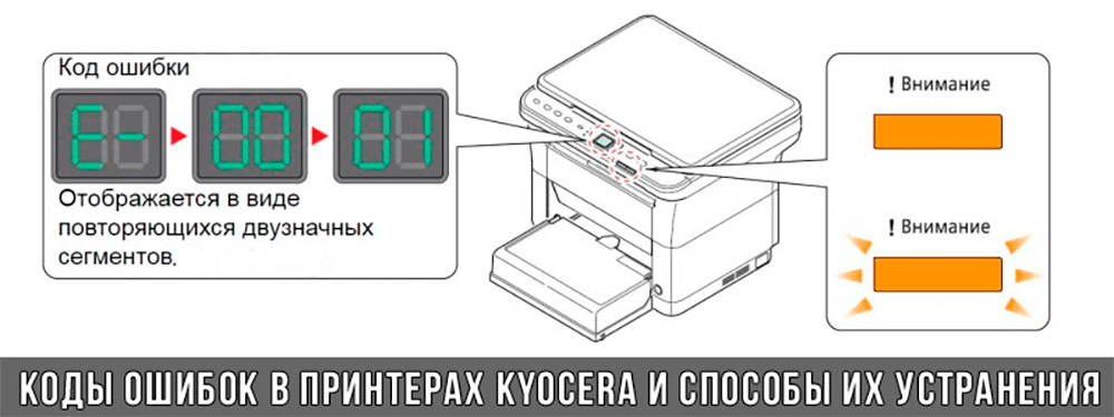
К счастью, оргтехника Kyocera оснащена системой самодиагностики (так же, как и струйные принтеры Canon). Поэтому, в случае возникновения проблемы, устройство самостоятельно выявит уязвимое место и сообщит Вам об этом миганием соответствующего индикатора на панели управления либо кодом ошибки, выведенным на дисплей принтера.
Если Вы не являетесь мастером по обслуживанию принтеров и МФУ Kyocera, то, чтобы понять, о чем сообщает печатающее устройство, Вам потребуется расшифровать указанный им код. Для этого мы добавили в статью таблицу кодов ошибок лазерных принтеров Kyocera серии FS и не только.
Коды ошибок принтеров и МФУ Kyocera, которые можно исправить самостоятельно
|
Код ошибки |
Значение ошибки |
Решение проблемы |
|
E-0001 (E1) |
Поврежден чип картриджа либо установлен неоригинальный картридж. |
Замените установленный картридж оригинальной версией изделия. Если хотите сэкономить, тогда купите и установите новый чип на картридж или перепрошейте принтер Kyocera. Однако предварительно не помешает попробовать сбросить ошибку соответствующей комбинацией клавиш (как это сделать, читайте в статье «Сброс ошибки установки неоригинального картриджа в принтерах Kyocera»). |
|
E-0002 (E2) |
Регион использования картриджа и принтера не совпадают. |
Замените чип или прошейте принтер Kyocera. |
|
E-0003 (E3) |
Заполнена память принтера или МФУ Kyocera. |
Отпечатайте ранее отсканированные листы или очистите очередь печати нажатием кнопки Стоп/Сброс (ранее отсканированные листы также удалятся из памяти принтера, даже если они еще не были распечатаны). |
|
E-0007 (E7) |
Тонер-картридж Kyocera израсходовал ресурс красящего вещества. |
Замените или заправьте картридж Kyocera (если используете совместимый или перезаправленный расходник, то после установки его в принтер не забудьте сбросить ошибку зажатием на 3-5 секунды кнопок [Ок] и [Сброс/Стоп]). |
|
E-0008 (E8) |
Открыта крышка принтера либо не работает датчик закрытия крышек устройства. |
Откройте и еще раз закройте переднюю и заднюю крышку принтера. Во время закрытия Вы должны услышать характерный щелчок. Если не помогло, то причина в неисправности датчика. |
|
E-0009 (E9) |
Лоток приема бумаги полон. |
Уберите все отпечатанные листы бумаги из выходящего лотка. Чтобы возобновить печать, нажмите кнопку [Старт]. |
|
E-0012 (E12) |
Ошибка памяти принтера Kyocera. |
Попробуйте уменьшить разрешение печати. Скорее всего, формат создаваемого отпечатка не соответствует возможностям принтера. |
|
E-0014 (E14) |
Установлен неверный формат бумаги (неподдерживаемый принтером Kyocera). |
Поменяйте бумагу на поддерживаемую принтером либо смените ее формат в настройках печати. Попробуйте обновить программное обеспечение. Возможно, это расширит поддерживаемые принтером Kyocera форматы. |
|
E-0015 (E15) |
Устройство не подключено к электрической сети либо на компьютере нет (не работает) драйвера принтера Kyocera. |
Проверьте подключение печатающего аппарата к электрической сети, а также целостность кабеля. Если ошибка не исчезает, скачайте драйвер принтера Kyocera и установите его на компьютер. |
|
E-0017 (E17) |
Ошибка передачи данных. |
Проверьте подключение принтера к компьютеру. Кабель не должен быть длиннее 5 метров, а также обязан поддерживать стандарт USB 2.0. Кроме того, переустановите драйвер принтера и утилиту Kyocera Client Tool. |
|
E-0018 (E18) |
Очередь печати заполнена. |
Очистите очередь печати нажатием кнопки [Сброс] либо через драйвер принтера. |
|
E-0019 (E19) |
Неверный формат печати. |
Отмените печать нажатием кнопки [Стоп/Сброс]. Выберите в настройках принтера соответствующий режим печати, а также установите в лоток поддерживаемый принтером формат бумаги. |
|
J-0000 (jam0000) |
Замятие бумаги за задней крышкой. |
Откройте крышку и извлеките бумагу. Проверьте надежность крепления бумаги в лотке, а также принтер на наличие посторонних предметов. Еще причина может быть в пружине выходного флажка. Если она растянулась, то может плохо работать фиксатор. Также проблема может быть из-за печки, сделайте ее ревизию, переборку и смазку. |
|
J-0501 (jam0501) |
Бумага застряла в принтере Kyocera |
Извлеките замятую бумагу. Проверьте надежность установки бумаги во входной лоток. Проверьте целостность роликов протяжки бумаги, а также принтер на наличие посторонних предметов. Если не помогло, стоит внимательно осмотреть ребра на направляющей пластине. На них могут образоваться сколы, трещины и заусенцы. Их можно слегка подчистить наждачной бумагой (нулевкой). |
|
J-0511 (jam0511) |
Принтер Kyocera замял бумагу. |
Извлеките замятую бумагу и повторите печать. Если проблема не исчезла, несите принтер в сервис. Скорее всего, изношен ролик протяжки бумаги. |
|
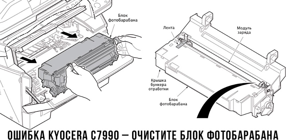
C7990 |
Бункер драм-картриджа (блока фотобарабана) заполнен отработанным тонером либо неисправен счетчик отработки красящего вещества. Еще проблема может быть в главной плате PWB. |
Осуществите чистку драм-картриджа (блока фотобарабана). Если проблема в датчике или плате, то нужно отнести принтер в СЦ на диагностику. |
|
F248 |
Ошибка обработки отпечатываемого материала. |
Перезагрузите принтер. Уберите неподдерживаемые спецсимволы из отпечатка. Обновите ПО принтера Kyocera. Смените режим работы принтера с PDL на GDI (Пуск -> Принтеры -> Свойства -> Параметры устройства). |
|
PF |
Отсутствует бумага в лотке подачи. |
Загрузите листы бумаги во входной лоток. Если принтер по-прежнему не печатает, значит нужно искать проблему в чем-то другом. |
|
1101 |
Ошибка сканирования через сеть из-за неправильного имени SMTP сервера. |
Пропишите DNS-адреса помимо прочих настроек печати по сети. |
|
1102 |
Некорректная настройка сканера для работы через сеть |
Зайдите в Web-панель управления принтером (нужно в адресную строку браузера ввести iP принтера Kyocera). Далее в зависимости от модели введите логин и пароль (Admin/Admin или просто admin00 без логина). Далее следуйте инструкции:
Логин и пароль нужны обязательно, если их нет, то следует создать. |
|
2101 |
Ошибка передачи данных при сканировании через сеть. |
Правильно настройте параметры (как для ошибки 1102), только предварительно отключите на ПК антивирус и брандмауэр. |
Если Вы испытали все способы, но не смогли убрать ошибку, то следует нести печатающее устройство в сервисный центр. Кроме того, есть ряд ошибок (высвечиваемых на дисплее принтера), которые нельзя устранить в домашних условиях. Соответствующие коды ошибок принтеров Kyocera представляем в очередной таблице.
Коды ошибок принтеров и МФУ Kyocera, которые нужно устранять в сервисном центре
|
Код ошибки |
Значение ошибки |
Решение проблемы |
|
0030 |
Неисправность платы управления факсом принтера. |
Замена платы. |
|
0100 |
Неисправность платы управления или флеш-памяти принтера. |
Замена платы. |
|
0120 |
Ошибка чтения mac-адреса из-за неисправности флеш-памяти принтера. |
Замена платы. |
|
0190 |
Неисправность платы управления или флеш-памяти принтера. |
Замена платы. |
|
0630 |
Неисправность платы управления принтера. |
Замена платы. |
|
1020 |
Неисправность мотора, привода или отсутствие контакта. |
Разборка принтера и замена изношенных частей. Проверка надежности подключений, замена разорванных (прогоревших) кабелей. Ремонт или замена привода мотора. |
|
1040 |
Неисправность мотора, привода или отсутствие контакта. |
Разборка принтера и замена изношенных частей. Проверка надежности подключений, замена разорванных (прогоревших) кабелей. Ремонт или замена привода мотора. |
|
2000 |
Неисправность главной платы управления, соединительного кабеля или привода принтера. |
Проверить ремни, шестерни и ролики привода. Смазать или заменить, если есть дефекты. Заменить привод или главную плату. |
|
3100 (C3100) |
Неисправность главной платы, привода сканера, датчика положения или нарушение целостности соединений. |
Проверить наличие разрывов и отсутствия контакта. Смазать или заменить изношенные элементы привода. Заменить привод, главную плату, датчик или соединительный кабель. Если Вам повезло, то возможно забыли отключить фиксатор блока сканера. |
|
3101 |
Сетевой кабель не подсоединен, или нарушена работа концентратора. Еще может быть из-за наличия вирусов в системе или неправильно заданным параметрам сервера SMTP. |
Проверить соединения, правильно настроить параметры сети. |
|
3300 |
Неисправность главной платы, датчика CIS или соединительного кабеля. |
Проверить контакты, заменить плату или датчик. |
|
3500 |
Неисправность главной платы или нарушение соединения контактов. |
Проверить контакты, заменить плату. |
|
4000 (C4000) |
Неисправность главной платы, привода сканера или нарушение соединений. Однако чаще всего ошибка лазера. |
Проверить контакты, заменить плату или привод блока сканера. Почистить лазер, смазать ось полигон-мотора, либо полностью заменить блок лазера. |
|
4200 |
Неисправность главной платы, блока сканера или датчика BD. |
Отключить питание принтера на 30 минут. Если не помогло, то следует заменить привод сканера или главную плату принтера. |
|
6000 (С6000) |
Неисправность главной платы, термостата, печки или нарушение соединения контактов. |
Проверить и поправить контакты. Заменить фьюзер. Ремонт или замена печки, термодатчика, термопредохранителя и т.д. |
|
6020 |
Сгорание термистора или главной платы. |
Замена термистора или главной платы. |
|
6030 |
Неисправность главной платы, термостата или термистора. Возможно, причина в отсутствии контакта. |
Проверить соединения. Заменить плату, термостат или термистор. |
|
6400 |
Неисправность главной платы, отсутствие питания или контакта. |
Заменить плату или источник питания. |
|
F000 |
Неисправность главной платы или отсутствие контакта. |
Проверить соединение ремня безопасности. Заменить ремень или плату управления. |
|
F020 |
Неисправность элементов памяти принтера. |
Перезагрузить принтер. Если ошибка не устранилась – заменить плату управления. |
|
F040 |
Неисправность главной платы принтера. |
Перезагрузить принтер. Если ошибка не устранилась – заменить плату управления. |
|
F05D |
Неисправность главной платы. Сбой программного оборудования привода. Проблемы с прошивкой принтера Kyocera. |
Перезагрузить принтер. Если ошибка не устранилась – заменить плату управления. Перепрошить принтер Kyocera. |
|
F245 F246 F247 F375 |
Принтер Kyocera заблокирован из-за проблемы, вызванной отказом источника питания. |
Нужно перепрошить принтер специальной сервисной микропрограммой. |
Обратите внимание: Если у печатающего устройства нет дисплея, то определить проблему можно по светодиодным индикаторам, встроенным в панель управления принтером. Например, у Kyocera Ecosys P2135D нужно сосчитать количество миганий индикаторов красного цвета и таким образом определить число, указывающее на ту или иную ошибку. В свою очередь, у модели Kyocera FS-1040 все зависит от темпа мигания светодиода с надписью «Внимание!» («Attention!»):
- Мигает медленно – указывает на отсутствие бумаги в лотке или тонера в картридже.
- Мигает быстро – оповещает о проблеме с памятью устройства, переполненном лотке или замятии бумаги, а также об использовании неоригинальных расходных материалов.
- Горит постоянно – говорит о проблемах с картриджем или фотобарабаном либо указывает на открытые крышки принтера.
Чтобы потребитель мог наверняка определить проблему, рекомендуем использовать утилиту Kyocera Client Tool, которая идет в комплекте с драйверами принтера.
Ваше Имя:
Ваш вопрос:
Внимание: HTML не поддерживается! Используйте обычный текст.
Оценка:
Плохо
Хорошо
Введите код, указанный на картинке:

Код C6400 является ошибкой Zero cross signal – сигнала пересечения нуля. Этот сигнал в машине используется для того, чтобы коммутировать лампу нагрева только в те моменты, когда переменное напряжение питающей сети 220В равно нулю, для снижения помех. Причина появления этого кода – проблемы питающей сети. Способ бороться – сброс через U163 – сброс ошибок блока фиксации.
Если машина выдает этот код часто – надо разбираться с электриками, рекомендовать подключить машину через 10-амперный сетевой фильтр и т.п.
Вернуться в раздел FAQ по Kyocera
- Code: C0030
- Description: FAX PWB system error
- Causes: The FAX processing cannot be continued due to the firmware error.
- Remedy: 1 Reinstalling the firmware The firmware is faulty. Reinstall the firmware.
2 Checking the connection The connector is not properly connected or the wire is faulty. Clean the terminal of the following wire connectors and reconnect the connectors. If there is no continuity, replace the wire. • FAX PWB — Main/engine PWB
3 Replacing the FAX PWB The FAX PWB is faulty. Replace the FAX PWB.
4 Main/engine PWB replacement The main/engine PWB is faulty. Replace the main/engine PWB.
- Code: C0070
- Description: FAX PWB incompatible detection error
- Causes: Abnormal detection of FAX control PWB incompatibility in the initial communication with the FAX control PWB, any normal communication command is not transmitted.
- Remedy: 1 Checking the FAX PWB The incompatible FAX PWB is installed. Install the FAX PWB for the applicable model.
2 Reinstalling the firmware The firmware is faulty. Reinstall the firmware.
- Code: C0100
- Description: Backup memory device error
- Causes: The abnormal status is output from the flash memory.
- Remedy: 1 Resetting the main power The EEPROM does not operate properly. Turn off the power switch and pull out the power plug. After passing 5s, reinsert the power plug and turn on the power switch.
2 Reinstalling the EEPROM The EEPROM is not properly attached. Reattach the EEPROM on the main/engine PWB.
3 Replacing the EEPROM The EEPROM is faulty. Replace the EEPROM on the main/engine PWB and execute U004 when C0180 appears
4 Checking the main/engine PWB The connector and FFC are not connected properly or the wire, FFC or PWB is faulty. Clean the terminal of the connectors on the main/engine PWB, reconnect the connector of the wire, and reconnect the FFC terminal. If the wire or the FFC is faulty, repair or replace them. If not resolved, replace the main/engine PWB.
- Code: C0120
- Description: MAC address data error
- Causes: MAC address data was incorrect data.
- Remedy: 1 Resetting the main power The flash memory does not operate properly. Turn off the power switch and pull out the power plug. After passing 5s, reinsert the power plug and turn on the power switch.
2 Main/engine PWB replacement The MAC address is incorrect. Replace the main/engine PWB when the MAC address is not indicated on the network status page.
- Code: C0130
- Description: Backup memory reading/writing error
- Causes: The reading or writing into the flash memory is unavailable.
- Remedy: 1 Resetting the main power The flash memory does not operate properly. Turn off the power switch and pull out the power plug. After passing 5s, reinsert the power plug and turn on the power switch.
2 Checking the main/engine PWB The connector and FFC are not connected properly or the wire, FFC or PWB is faulty. Clean the terminal of the connectors on the main/engine PWB, reconnect the connector of the wire, and reconnect the FFC terminal. If the wire or the FFC is faulty, repair or replace them. If not resolved, replace the main/engine PWB.
- Code: C0140
- Description: Backup memory data error
- Causes: The data read from the flash memory is judged as abnormal at the startup.
- Remedy: 1 Resetting the main power The flash memory does not operate properly. Turn off the power switch and pull out the power plug. After passing 5s, reinsert the power plug and turn on the power switch.
2 Executing U021 The flash memory does not operate properly. Execute U021.
3 Checking the main/engine PWB The connector and FFC are not connected properly or the wire, FFC or PWB is faulty. Clean the terminal of the connectors on the main/engine PWB, reconnect the connector of the wire, and reconnect the FFC terminal. If the wire or the FFC is faulty, repair or replace them. If not resolved, replace the main/engine PWB.
- Code: C0150
- Description: EEPROM writing / reading error
- Causes: 1. No response from the device is detected for 5ms or more 5 times continuously when reading / writing the data. 2. The reading data of 2 points mismatches 8 times continuously. 3. The reading data and the writing data mismatch 8 times continuously.
- Remedy: 1 Resetting the main power The EEPROM does not operate properly. Turn off the power switch and pull out the power plug. After passing 5s, reinsert the power plug and turn on the power switch.
2 Reinstalling the EEPROM The EEPROM is not properly attached. Reattach the EEPROM on the main/engine PWB.
3 Replacing the EEPROM The EEPROM is faulty. Replace the EEPROM on the main/engine PWB and execute U004.
4 Checking the main/engine PWB The connector and FFC are not connected properly or the wire, FFC or PWB is faulty. Clean the terminal of the connectors on the main/engine PWB, reconnect the connector of the wire, and reconnect the FFC terminal. If the wire or the FFC is faulty, repair or replace them. If not resolved, replace the main/engine PWB.
- Code: C0160
- Description: EEPROM data error
- Causes: The data read from the EEPROM is judged as abnormal.
- Remedy: 1 Resetting the main power The EEPROM does not operate properly. Turn off the power switch and pull out the power plug. After passing 5s, reinsert the power plug and turn on the power switch.
2 Executing U021 The data stored in the EEPROM on the main/ engine PWB is faulty. Execute U021.
3 Replacing the EEPROM The EEPROM is faulty. Replace the EEPROM on the main/engine PWB and execute U004.
- Code: C0170
- Description: Charger count error
- Causes: The values in one of the billing counters, life counter or the scanner counter mismatch between the main side and the engine side.
- Remedy: 1 Reinstalling the EEPROM The EEPROM for the different main unit is installed. Execute U004 to check machine serial number at MAIN and ENGINE. If different numbers are displayed, attach the proper EEPROM to the main/engine PWB
2 Replacing the EEPROM The EEPROM is faulty. Replace the EEPROM on the main/engine PWB and execute U004 when C0180 appears
3 Checking the main/engine PWB The connector and FFC are not connected properly or the wire, FFC or PWB is faulty. Clean the terminal of the connectors on the main/engine PWB, reconnect the connector of the wire, and reconnect the FFC terminal. If the wire or the FFC is faulty, repair or replace them. If not resolved, replace the main/engine PWB.
- Code: C0180
- Description: Machine serial number mismatch
- Causes: The machine serial Nos. in the main PWB and the EEPROM on the engine PWB mismatch when turning the power on.
- Remedy: 1 Reinstalling the EEPROM The EEPROM for the different main unit is installed. Execute U004 to check machine serial number at MAIN and ENGINE. If different numbers are displayed, attach the proper EEPROM to the main/engine PWB
2 Replacing the EEPROM The EEPROM is faulty. Replace the EEPROM on the main/engine PWB and execute U004 when C0180 appears
- Code: C0190
- Description: Backup memory device error
- Causes: Data from the FRAM cannot be read at start-up (3 times retries)
- Remedy: 1 Resetting the main power FRAM (main/engine PWB) is faulty. Turn off the power switch and pull out the power plug. After passing 5s, reinsert the power plug and turn on the power switch.
2 Checking the main/engine PWB The connector and FFC are not connected properly or the wire, FFC or PWB is faulty. Clean the terminal of the connectors on the main/engine PWB, reconnect the connector of the wire, and reconnect the FFC terminal. If the wire or the FFC is faulty, repair or replace them. If not resolved, replace the main/engine PWB.
- Code: C0360
- Description: Communication error between the engine PWB and ASIC
- Causes: The checksum error appears or the video signal is not reversed when checking the read-back data after transmitting the data. (Successive failure 10 times)
- Remedy: 1 Resetting the main power The main/engine PWB does not operate correctly. Turn off the power switch and pull out the power plug. After passing 5s, reinsert the power plug and turn on the power switch.
2 Checking the engine relay PWB The connector and FFC are not connected properly or the wire, FFC or PWB is faulty. Clean the terminal of the connectors on the engine relay PWB, reconnect the connector of the wire, and reconnect the FFC terminal. If the wire or the FFC is faulty, repair or replace them. If not resolved, replace the engine relay PWB.
3 Checking the main/engine PWB The connector and FFC are not connected properly or the wire, FFC or PWB is faulty. Clean the terminal of the connectors on the main/engine PWB, reconnect the connector of the wire, and reconnect the FFC terminal. If the wire or the FFC is faulty, repair or replace them. If not resolved, replace the main/engine PWB.
- Code: C0640
- Description: Hard Disk (SSD) error
- Causes: The SSD I/O error is detected when accessing the file after the ready mode. (SSD format error after restart such as the system initialization, Sanitization or encrypted format after introducing the security kit)
- Remedy: 1 Resetting the main power The main/engine PWB does not operate correctly. Turn off the power switch and pull out the power plug. After passing 5s, reinsert the power plug and turn on the power switch.
2 Reinstalling HD-6/7 (SSD) The HD-6/7 (SSD) is not connected to the KUIO connector of the main/ engine PWB Turn the power switch off and disconnect the power cord. Check the HD-6/7 (SSD) is connected to the KUIO connector of the main/engine PWB properly and reinstalled the HD-6/7 (SSD).
3 Initializing HD-6/7 (SSD) HD-6 or HD-7 (SSD) does not operate correctly. Initialize the HD-6/7 (SSD) at [System Menu/Counter] key > [Adjustment/Maintenance] > [Service Settings] > [SSD Format].
4 Main/engine PWB replacement The main/engine PWB is faulty. Replace the main/engine PWB.
- Code: C0800
- Description: Image processing error
- Causes: The print sequence jam (J010x) is detected 2 times in succession.
- Remedy: 1 Checking the image data The image data is faulty. When this issue occurs only when handling the certain image data, check if the image data is faulty.
2 Checking the situation The printing operation of the certain file is faulty. Acquire the job’s log if the phenomenon can be reproduced by specifying the job when the error was detected.
3 Checking the main/engine PWB The connector and FFC are not connected properly or the wire, FFC or PWB is faulty. Clean the terminal of the connectors on the main/engine PWB, reconnect the connector of the wire, and reconnect the FFC terminal. If the wire or the FFC is faulty, repair or replace them. If not resolved, replace the main/engine PWB.
- Code: C0830
- Description: FAX PWB flash program area checksum error
- Causes: The program stored in the flash memory is broken so it cannot perform.
- Remedy: 1 Reinstalling the firmware The firmware is faulty. Reinstall the firmware.
2 Initializing the fax The FAX data is faulty. Execute U600 to initialize the FAX.
3 Checking the connection The connector is not properly connected or the wire is faulty. Clean the terminal of the following wire connectors and reconnect the connectors. If there is no continuity, replace the wire. • FAX PWB — Main/engine PWB
4 Replacing the FAX PWB The FAX PWB is faulty. Replace the FAX PWB.
5 Main/engine PWB replacement The main/engine PWB is faulty. Replace the main/engine PWB.
- Code: C0840
- Description: RTC error (‘Time for maintenance T’ appears)
- Causes: [Check at start-up] • RTC values are old. • Power has not been turned on for over 5 years. • RTC value is older than 2000/1/1 00:01. [Periodic check per 5 minutes after start-up] • RTC values are older than the ones at the last check. • Partial operation by power reset after C840 error and ‘Time for Maintenance T’ is indicated.
- Remedy: 1 Setting the RTC RTC is not properly set. Set the RTC in the System Menu.
2 Checking the life of the backup battery The backup battery has run out. If the same service call error appears after resetting the power, check the backup battery. If it has run out, replace the backup battery on the main/engine PWB.
3 Reattaching the main/ engine PWB The main/engine PWB is not properly attached. Retighten the screws for the main/engine PWB.
4 Checking the main/engine PWB The connector and FFC are not connected properly or the wire, FFC or PWB is faulty. Clean the terminal of the connectors on the main/engine PWB, reconnect the connector of the wire, and reconnect the FFC terminal. If the wire or the FFC is faulty, repair or replace them. If not resolved, replace the main/engine PWB.
- Code: C0870
- Description: Image data transmission error to FAX PWB
- Causes: Data was not properly transmitted even if the specified times of retry were made when the large volume data is transmitted into the FAX PWB
- Remedy: 1 Reinstalling the firmware The firmware is faulty. Reinstall the firmware.
2 Initializing the fax The FAX data is faulty. Execute U600 to initialize the FAX.
3 Checking the connection The connector is not properly connected or the wire is faulty. Clean the terminal of the following wire connectors and reconnect the connectors. If there is no continuity, replace the wire. • FAX PWB — Main/engine PWB
4 Replacing the FAX PWB The FAX PWB is faulty. Replace the FAX PWB.
5 Main/engine PWB replacement The main/engine PWB is faulty. Replace the main/engine PWB.
- Code: C0920
- Description: FAX file system error
- Causes: The backup data cannot be stored in the flash memory device due to the file system error
- Remedy: 1 Reinstalling the firmware The firmware is faulty. Reinstall the firmware.
2 Initializing the fax The FAX data is faulty. Execute U600 to initialize the FAX.
3 Checking the connection The connector is not properly connected or the wire is faulty. Clean the terminal of the following wire connectors and reconnect the connectors. If there is no continuity, replace the wire. • FAX PWB — Main/engine PWB
4 Replacing the FAX PWB The FAX PWB is faulty. Replace the FAX PWB.
5 Main/engine PWB replacement The main/engine PWB is faulty. Replace the main/engine PWB.
- Code: C1010
- Description: Lift motor error
- Causes: After installing cassette 1, either of the following 1 to 4 is detected 5 times continuously. 1. The lift motor excess current is detected for 80ms. 2. The lift sensor does not turn on when passing 10s after installing the cassette. 3. During printing, after detecting the lift sensor off, the lift sensor does not turn on when passing 1s after the ascending control. 4. During motor operation, the lock signal is detected for 1s continuously and it is detected 5 times continuously.
- Remedy: 1 Checking the lift plate The lift plate does not operate properly. If the lift plate does not ascend or descend, correct it or replace it.
2 Checking the drive gear The drive gear does not rotate properly. Check if MP lift plate elevation drive gears rotate or have no excessive load. And apply the grease to the frictional parts and repair the related parts so that they can rotate properly.
3 Checking the connection The connector or FFC is not connected properly. Or, the wire or FFC is faulty. Reconnect the following wire connectors and clean the FFC and reconnect. If there is no continuity, replace the wire. If the FFC terminal section is deformed or FFC is broken, replace the FFC. • Lift sensor — Engine relay PWB • Engine relay PWB — Main/ engine PWB
4 Checking the lift motor The lift motor is not properly attached, or it is faulty. Reattach the lift motor. If it is not repaired, replace it.
5 Checking the lift sensor The lift sensor is not properly attached, or it is faulty. Reattach PF lift upper limit sensor. If not repaired, replace it.
6 Replacing the engine relay PWB The engine relay PWB is faulty. Replace the engine relay PWB.
7 Firmware upgrade The firmware is not the latest version. Upgrade the engine firmware to the latest version
8 Main/engine PWB replacement The main/engine PWB is faulty. Replace the main/engine PWB.
- Code: C1020
- Description: PF lift motor 1 error
- Causes: Target: Paper feeder (1st) After installing the cassette, either of the following 1 to 3 is detected 5 times continuously. 1. The PF lift motor excess current is detected for 80ms. 2. The PF lift sensor does not turn on when passing 10s after installing the cassette. 3. During printing, after detecting the PF lift sensor off, the PF lift sensor does not turn on when passing 1s after the ascending control.
- Remedy: 1 Checking the lift plate The lift plate does not operate properly. If the lift plate does not ascend or descend, correct it or replace it.
2 Checking the drive gear The drive gear does not rotate properly. Check if MP lift plate elevation drive gears rotate or have no excessive load. And apply the grease to the frictional parts and repair the related parts so that they can rotate properly.
3 Reinstalling the paper feeder The paper feeder is not properly installed. Reinstall the paper feeder
4 Checking the connection The connector is not connected properly or, the wire or drawer connector is faulty. Check the following wire connection, and correct the terminals and reconnect the connectors all the way. If the wire has no continuity or the drawer connector is faulty, replace them.• PF lift sensor — PF PWB• PF lift motor — PF PWB• PF PWB — Drawer connector• Drawer connector — PF PWB (2nd paper feeder)
5 Checking the PF lift motor PF lift motor is not attached properly or faulty. Reattach the PF lift motor. If it is not repaired, replace it.
6 Checking the PF lift sensor The PF lift motor is not properly attached, or it is faulty. Reattach the PF lift sensor. If it is not repaired, replace it.
7 Replacing the PF PWB The PF PWB is faulty. Replace the PF PWB.
8 Firmware upgrade The firmware is not the latest version. Upgrade the engine firmware to the latest version
9 Replacing the engine relay PWB The engine relay PWB is faulty. Replace the engine relay PWB.
- Code: C1030
- Description: PF lift motor 2 error
- Causes: Target: Paper feeder (2nd) After installing the cassette, either of the following 1 to 3 is detected 5 times continuously. 1. The PF lift motor excess current is detected for 80ms. 2. The PF lift sensor does not turn on when passing 10s after installing the cassette. 3. During printing, after detecting the PF lift sensor off, the PF lift sensor does not turn on when passing 1s after the ascending control.
- Remedy: 1 Checking the lift plate The lift plate does not operate properly. If the lift plate does not ascend or descend, correct it or replace it.
2 Checking the drive gear The drive gear does not rotate properly. Check if MP lift plate elevation drive gears rotate or have no excessive load. And apply the grease to the frictional parts and repair the related parts so that they can rotate properly.
3 Reinstalling the paper feeder The paper feeder is not properly installed. Reinstall the paper feeder
3 Checking the connection The connector is not connected properly or, the wire or drawer connector is faulty. Check the following wire connection, and correct the terminals and reconnect the connectors all the way. If the wire has no continuity or the drawer connector is faulty, replace them.• PF lift sensor — PF PWB• PF lift motor — PF PWB• PF PWB — Drawer connector• Drawer connector — PF PWB (2nd paper feeder)
4 Checking the PF lift motor PF lift motor is not attached properly or faulty. Reattach the PF lift motor. If it is not repaired, replace it.
5 Checking the PF lift sensor The PF lift motor is not properly attached, or it is faulty. Reattach the PF lift sensor. If it is not repaired, replace it.
6 Replacing the PF PWB The PF PWB is faulty. Replace the PF PWB.
- Code: C1040
- Description: PF lift motor 3 error
- Causes: Target: Paper feeder (3rd) After installing the cassette, either of the following 1 to 3 is detected 5 times continuously. 1. The PF lift motor excess current is detected for 80ms. 2. The PF lift sensor does not turn on when passing 10s after installing the cassette. 3. During printing, after detecting the PF lift sensor off, the PF lift sensor does not turn on when passing 1s after the ascending control.
- Remedy: 1 Checking the lift plate The lift plate does not operate properly. If the lift plate does not ascend or descend, correct it or replace it.
2 Checking the drive gear The drive gear does not rotate properly. Check if MP lift plate elevation drive gears rotate or have no excessive load. And apply the grease to the frictional parts and repair the related parts so that they can rotate properly.
3 Reinstalling the paper feeder The paper feeder is not properly installed. Reinstall the paper feeder
4 Checking the connection The connector is not connected properly or, the wire or drawer connector is faulty. Check the following wire connection, and correct the terminals and reconnect the connectors all the way. If the wire has no continuity or the drawer connector is faulty, replace them.• PF lift sensor — PF PWB• PF lift motor — PF PWB• PF PWB — Drawer connector• Drawer connector — PF PWB (2nd paper feeder)
5 Checking the PF lift motor PF lift motor is not attached properly or faulty. Reattach the PF lift motor. If it is not repaired, replace it.
6 Checking the PF lift sensor The PF lift motor is not properly attached, or it is faulty. Reattach the PF lift sensor. If it is not repaired, replace it.
7 Replacing the PF PWB The PF PWB is faulty. Replace the PF PWB.
- Code: C1810
- Description: Paper Feeder communication error
- Causes: Target: Paper feeder (1st) The communication error was detected 10 times continuously.
- Remedy: 1 Reinstalling the paper feeder The paper feeder is not properly installed. Reinstall the paper feeder
2 Checking the connection The connector is not connected properly or, the wire or drawer connector is faulty. Check the following wire connection, and correct the terminals and reconnect the connectors all the way. If the wire has no continuity or the drawer connector is faulty, replace them.• PF lift sensor — PF PWB• PF lift motor — PF PWB• PF PWB — Drawer connector• Drawer connector — PF PWB (2nd paper feeder)
3 Firmware upgrade The firmware is not the latest version. Upgrade the firmware to the latest version.
4 Replacing the PF PWB The PF PWB is faulty. Replace the PF PWB.
5 Replacing the engine relay PWB The engine relay PWB is faulty. Replace the engine relay PWB.
- Code: C1820
- Description: Paper feeder communication error
- Causes: Target: Paper feeder (2nd) The communication error was detected 10 times continuously.
- Remedy: 1 Reinstalling the paper feeder The paper feeder is not properly installed. Reinstall the paper feeder
2 Checking the connection The connector is not connected properly or, the wire or drawer connector is faulty. Check the following wire connection, and correct the terminals and reconnect the connectors all the way. If the wire has no continuity or the drawer connector is faulty, replace them.• PF lift sensor — PF PWB• PF lift motor — PF PWB• PF PWB — Drawer connector• Drawer connector — PF PWB (2nd paper feeder)
3 Firmware upgrade The firmware is not the latest version. Upgrade the firmware to the latest version.
4 Replacing the PF PWB The PF PWB is faulty. Replace the PF PWB.
5 Replacing the PF PWB The PF PWB is faulty. Replace the PF PWB in the 1st paper feeder.
- Code: C1830
- Description: Paper feeder communication error
- Causes: Target: Paper feeder (3rd) The communication error was detected 10 times continuously.
- Remedy: 1 Reinstalling the paper feeder The paper feeder is not properly installed. Reinstall the paper feeder
2 Checking the connection The connector is not connected properly or, the wire or drawer connector is faulty. Check the following wire connection, and correct the terminals and reconnect the connectors all the way. If the wire has no continuity or the drawer connector is faulty, replace them.• PF lift sensor — PF PWB• PF lift motor — PF PWB• PF PWB — Drawer connector• Drawer connector — PF PWB (2nd paper feeder)
3 Firmware upgrade The firmware is not the latest version. Upgrade the firmware to the latest version.
4 Replacing the PF PWB The PF PWB is faulty. Replace the PF PWB.
5 Replacing the PF PWB The PF PWB is faulty. Replace the PF PWB in the 2nd paper feeder.
- Code: C1900
- Description: Paper Feeder EEPROM error
- Causes: Target: Paper feeder (1st) For the internal count The writing data and the reading data mismatch 4 times continuously when writing.
- Remedy: 1 Reinstalling the paper feeder The paper feeder is not properly installed. Reinstall the paper feeder
2 Checking the connection The connector is not properly connected or the wire is faulty. Reinsert the connectors into all the connectors on the PF PWB. Also, if there is no continuity, replace the wire.
3 Replacing the PF PWB The PF PWB is faulty. Replace the PF PWB.
- Code: C1910
- Description: Paper feeder EEPROM error
- Causes: Target: Paper feeder (2nd) For the internal count The writing data and the reading data mismatch 4 times continuously when writing.
- Remedy: 1 Reinstalling the paper feeder The paper feeder is not properly installed. Reinstall the paper feeder
2 Checking the connection The connector is not properly connected or the wire is faulty. Reinsert the connectors into all the connectors on the PF PWB. Also, if there is no continuity, replace the wire.
3 Replacing the PF PWB The PF PWB is faulty. Replace the PF PWB.
- Code: C1920
- Description: Paper feeder EEPROM error
- Causes: Target: Paper feeder (3rd) For the internal count The writing data and the reading data mismatch 4 times continuously when writing.
- Remedy: 1 Reinstalling the paper feeder The paper feeder is not properly installed. Reinstall the paper feeder
2 Checking the connection The connector is not properly connected or the wire is faulty. Reinsert the connectors into all the connectors on the PF PWB. Also, if there is no continuity, replace the wire.
3 Replacing the PF PWB The PF PWB is faulty. Replace the PF PWB.
- Code: C2101
- Description: Developer motor steady state error
- Causes: The steady signal turns off for 2s continuously after the motor is stabilized.
- Remedy: 1 Checking the developer unit The developer roller is faulty. Replace developer unit C, M or Y if the developer roller does not rotate.
2 Checking the driving parts The developer motor drive is not transmitted correctly. Check if the drive gear rotates smoothly and has no excessive load. And apply the grease to the frictional parts and repair the related parts so that the drive gear rotates smoothly.
3 Checking the connection The connector or FFC is not connected properly. Or, the wire or FFC is faulty. Reconnect the following wire connectors and clean the FFC and reconnect. If there is no continuity, replace the wire. If the FFC terminal section is deformed or FFC is broken, replace the FFC. • Developer motor — Engine relay PWB • Engine relay PWB — Main/ engine PWB
4 Checking the developer motor The developer motor is not properly attached, or it is faulty. Reattach the developer motor. If it is not repaired, replace it.
5 Firmware upgrade The firmware is not the latest version. Upgrade the engine firmware to the latest version
6 Replacing the engine relay PWB The engine relay PWB is faulty. Replace the engine relay PWB.
7 Main/engine PWB replacement The main/engine PWB is faulty. Replace the main/engine PWB.
- Code: C2111
- Description: Developer motor start-up error
- Causes: The steady signal does not turn on after passing 3s since the motor started up
- Remedy: 1 Checking the developer unit The developer roller is faulty. Replace developer unit C, M or Y if the developer roller does not rotate.
2 Checking the driving parts The developer motor drive is not transmitted correctly. Check if the drive gear rotates smoothly and has no excessive load. And apply the grease to the frictional parts and repair the related parts so that the drive gear rotates smoothly.
3 Checking the connection The connector or FFC is not connected properly. Or, the wire or FFC is faulty. Reconnect the following wire connectors and clean the FFC and reconnect. If there is no continuity, replace the wire. If the FFC terminal section is deformed or FFC is broken, replace the FFC. • Developer motor — Engine relay PWB • Engine relay PWB — Main/ engine PWB
4 Checking the developer motor The developer motor is not properly attached, or it is faulty. Reattach the developer motor. If it is not repaired, replace it.
5 Firmware upgrade The firmware is not the latest version. Upgrade the engine firmware to the latest version
6 Replacing the engine relay PWB The engine relay PWB is faulty. Replace the engine relay PWB.
7 Main/engine PWB replacement The main/engine PWB is faulty. Replace the main/engine PWB.
- Code: C2201
- Description: Drum motor 2 steady-state error
- Causes: The steady signal turns off for 2s continuously after the motor is stabilized.
- Remedy: 1 Checking the drum unit and the developer unit The drum does not rotate smoothly. Check if the drum and the drum cleaning screw rotates manually. If it locks up, replace drum unit C or Y.
2 Checking the driving parts The drum motor 2 drive is not transmitted correctly. Check if the drive gear rotates smoothly and has no excessive load. And apply the grease to the frictional parts and repair the related parts so that the drive gear rotates smoothly.
3 Checking the connection The connector or FFC is not connected properly. Or, the wire or FFC is faulty. Reconnect the following wire connectors and clean the FFC and reconnect. If there is no continuity, replace the wire. If the FFC terminal section is deformed or FFC is broken, replace the FFC. • Drum motor 2 — Engine relay PWB • Engine relay PWB — Main/ engine PWB
4 Checking drum motor 2 Drum motor 2 is not properly attached, or it is faulty. Reattach drum motor 2. If it is not repaired, replace it.
5 Firmware upgrade The firmware is not the latest version. Upgrade the engine firmware to the latest version
6 Replacing the engine relay PWB The engine relay PWB is faulty. Replace the engine relay PWB.
7 Main/engine PWB replacement The main/engine PWB is faulty. Replace the main/engine PWB.
- Code: C2202
- Description: Drum motor 1 steady-state error
- Causes: The steady signal turns off for 2s continuously after the motor is stabilized.
- Remedy: 1 Checking the drum unit and the developer unit The drum does not rotate smoothly. Check if the drum and the drum cleaning screw rotates manually. If it locks up, replace drum unit K or M.
2 Checking the driving parts The drum motor 1 drive is not transmitted correctly. Check if the drive gear rotates smoothly and has no excessive load. And apply the grease to the frictional parts and repair the related parts so that the drive gear rotates smoothly.
3 Checking the connection The connector or FFC is not connected properly. Or, the wire or FFC is faulty. Reconnect the following wire connectors and clean the FFC and reconnect. If there is no continuity, replace the wire. If the FFC terminal section is deformed or FFC is broken, replace the FFC. • Drum motor 1 — Engine relay PWB • Engine relay PWB — Main/ engine PWB
4 Checking drum motor 1 Drum motor 1 is not properly attached, or it is faulty. Reattach drum motor 1. If it is not repaired, replace it.
5 Firmware upgrade The firmware is not the latest version. Upgrade the engine firmware to the latest version
6 Replacing the engine relay PWB The engine relay PWB is faulty. Replace the engine relay PWB.
7 Main/engine PWB replacement The main/engine PWB is faulty. Replace the main/engine PWB.
- Code: C2211
- Description: Drum motor 2 standby error
- Causes: The steady signal does not turn on after passing 3s since the motor started up
- Remedy: 1 Checking the drum unit and the developer unit The drum does not rotate smoothly. Check if the drum and the drum cleaning screw rotates manually. If it locks up, replace drum unit C or Y.
2 Checking the driving parts The drum motor 2 drive is not transmitted correctly. Check if the drive gear rotates smoothly and has no excessive load. And apply the grease to the frictional parts and repair the related parts so that the drive gear rotates smoothly.
3 Checking the connection The connector or FFC is not connected properly. Or, the wire or FFC is faulty. Reconnect the following wire connectors and clean the FFC and reconnect. If there is no continuity, replace the wire. If the FFC terminal section is deformed or FFC is broken, replace the FFC. • Drum motor 2 — Engine relay PWB • Engine relay PWB — Main/ engine PWB
4 Checking drum motor 2 Drum motor 2 is not properly attached, or it is faulty. Reattach drum motor 2. If it is not repaired, replace it.
5 Firmware upgrade The firmware is not the latest version. Upgrade the engine firmware to the latest version
6 Replacing the engine relay PWB The engine relay PWB is faulty. Replace the engine relay PWB.
7 Main/engine PWB replacement The main/engine PWB is faulty. Replace the main/engine PWB.
- Code: C2212
- Description: Drum motor 1 standby error
- Causes: The steady signal does not turn on after passing 3s since the motor started up
- Remedy: 1 Checking the drum unit and the developer unit The drum does not rotate smoothly. Check if the drum and the drum cleaning screw rotates manually. If it locks up, replace drum unit K or M.
2 Checking the driving parts The drum motor 1 drive is not transmitted correctly. Check if the drive gear rotates smoothly and has no excessive load. And apply the grease to the frictional parts and repair the related parts so that the drive gear rotates smoothly.
3 Checking the connection The connector or FFC is not connected properly. Or, the wire or FFC is faulty. Reconnect the following wire connectors and clean the FFC and reconnect. If there is no continuity, replace the wire. If the FFC terminal section is deformed or FFC is broken, replace the FFC. • Drum motor 1 — Engine relay PWB • Engine relay PWB — Main/ engine PWB
4 Checking drum motor 1 Drum motor 1 is not properly attached, or it is faulty. Reattach drum motor 1. If it is not repaired, replace it.
5 Firmware upgrade The firmware is not the latest version. Upgrade the engine firmware to the latest version
6 Replacing the engine relay PWB The engine relay PWB is faulty. Replace the engine relay PWB.
7 Main/engine PWB replacement The main/engine PWB is faulty. Replace the main/engine PWB.
- Code: C2500
- Description: Conveying developer motor error
- Causes: The steady signal does not turn on after passing 3s since the motor started up or the steady signal turns off for 2s continuously after the motor is stabilized
- Remedy: 1 Checking the driving parts The conveying developer motor drive is not transmitted correctly. Check if the paper conveying roller and the drive gear rotate smoothly and have no excessive load. And apply the grease to the frictional parts and repair the related parts so that the drive gear rotates smoothly.
2 Checking the connection The connector or FFC is not connected properly. Or, the wire or FFC is faulty. Reconnect the following wire connectors and clean the FFC and reconnect. If there is no continuity, replace the wire. If the FFC terminal section is deformed or FFC is broken, replace the FFC. • Conveying developer motor — Engine relay PWB • Engine relay PWB — Main/ engine PWB • LSU — Main/engine PWB
3 Checking the conveying developer motor The conveying developer motor is not properly attached, or it is faulty. Reattach the conveying developer motor. If it is not repaired, replace it.
4 Replacing the conveying drive unit The conveying drive unit is faulty. Replace the conveying drive unit.
5 Firmware upgrade The firmware is not the latest version. Upgrade the engine firmware to the latest version
6 Replacing the engine relay PWB The engine relay PWB is faulty. Replace the engine relay PWB.
7 Main/engine PWB replacement The main/engine PWB is faulty. Replace the main/engine PWB.
- Code: C2600
- Description: PF feed motor error
- Causes: Target: Paper feeder (1st) The steady signal does not turn on for 5s continuously when the motor drives
- Remedy: 1 Checking the driving parts The PF feed motor drive is not transmitted correctly. Check if the PF feed roller or the drive gear rotates or have no excessive load. And apply the grease to the frictional parts and repair the related parts so that the drive gear rotates properly.
2 Checking the connection The connector is not properly connected or the wire is faulty. Clean the terminal of the following wire connectors and reconnect the connectors. If there is no continuity, replace the wire. • PF feed motor — PF PWB
3 Checking the PF feed motor The PF feed motor is not properly attached, or it is faulty. Reattach the PF feed motor. If it is not repaired, replace it.
4 Replacing the PF PWB The PF PWB is faulty. Replace the PF PWB.
- Code: C2610
- Description: PF feed motor error
- Causes: Target: Paper feeder (2nd) The steady signal does not turn on for 5s continuously when the motor drives
- Remedy: 1 Checking the driving parts The PF feed motor drive is not transmitted correctly. Check if the PF feed roller or the drive gear rotates or have no excessive load. And apply the grease to the frictional parts and repair the related parts so that the drive gear rotates properly.
2 Checking the connection The connector is not properly connected or the wire is faulty. Clean the terminal of the following wire connectors and reconnect the connectors. If there is no continuity, replace the wire. • PF feed motor — PF PWB
3 Checking the PF feed motor The PF feed motor is not properly attached, or it is faulty. Reattach the PF feed motor. If it is not repaired, replace it.
4 Replacing the PF PWB The PF PWB is faulty. Replace the PF PWB.
- Code: C2620
- Description: PF feed motor error
- Causes: Target: Paper feeder (3rd) The steady signal does not turn on for 5s continuously when the motor drives
- Remedy: 1 Checking the driving parts The PF feed motor drive is not transmitted correctly. Check if the PF feed roller or the drive gear rotates or have no excessive load. And apply the grease to the frictional parts and repair the related parts so that the drive gear rotates properly.
2 Checking the connection The connector is not properly connected or the wire is faulty. Clean the terminal of the following wire connectors and reconnect the connectors. If there is no continuity, replace the wire. • PF feed motor — PF PWB
3 Checking the PF feed motor The PF feed motor is not properly attached, or it is faulty. Reattach the PF feed motor. If it is not repaired, replace it.
4 Replacing the PF PWB The PF PWB is faulty. Replace the PF PWB.
- Code: C2760
- Description: Primary transfer motor startup error
- Causes: The steady signal does not turn on after passing 3s since the motor started up
- Remedy: 1 Checking the driving parts The primary transfer motor drive is not transmitted correctly. Check if the excessive load is given by rotating the drive gears, roller and the transfer belt, and clean the drive section for the primary transfer unit.
2 Checking the connection The connector or FFC is not connected properly. Or, the wire or FFC is faulty. Reconnect the following wire connectors and clean the FFC and reconnect. If there is no continuity, replace the wire. If the FFC terminal section is deformed or FFC is broken, replace the FFC. • Primary transfer motor — Engine relay PWB • Engine relay PWB — Main/ engine PWB
3 Checking the primary transfer motor The primary transfer motor is not properly attached, or it is faulty. Reattach the primary transfer motor. If it is not repaired, replace it.
4 Firmware upgrade The firmware is not the latest version. Upgrade the engine firmware to the latest version
5 Replacing the engine relay PWB The engine relay PWB is faulty. Replace the engine relay PWB.
6 Main/engine PWB replacement The main/engine PWB is faulty. Replace the main/engine PWB.
- Code: C2820
- Description: Primary transfer motor steady-state error
- Causes: The steady signal turns off for 2s continuously after the motor is stabilized.
- Remedy: 1 Checking the driving parts The primary transfer motor drive is not transmitted correctly. Check if the excessive load is given by rotating the drive gears, roller and the transfer belt, and clean the drive section for the primary transfer unit.
2 Checking the connection The connector or FFC is not connected properly. Or, the wire or FFC is faulty. Reconnect the following wire connectors and clean the FFC and reconnect. If there is no continuity, replace the wire. If the FFC terminal section is deformed or FFC is broken, replace the FFC. • Primary transfer motor — Engine relay PWB • Engine relay PWB — Main/ engine PWB
3 Checking the primary transfer motor The primary transfer motor is not properly attached, or it is faulty. Reattach the primary transfer motor. If it is not repaired, replace it.
4 Firmware upgrade The firmware is not the latest version. Upgrade the engine firmware to the latest version
5 Replacing the engine relay PWB The engine relay PWB is faulty. Replace the engine relay PWB.
6 Main/engine PWB replacement The main/engine PWB is faulty. Replace the main/engine PWB.
- Code: C3100
- Description: Scanner carriage error
- Causes: The home position is not correct when the power is turned on or at the end of a reading process of the table or document processor.
- Remedy: 1 Checking the scanner carriage A load is applied to the scanner movement. If there is an excessive load when manually operating the scanner carriage, check if foreign objects is on the drive belt. Then, clean the drive belt and after that, apply the grease to the ISU shaft.
2 Checking the connection The connector or FFC is not connected properly. Or, the wire or FFC is faulty. Reconnect the following wire connectors and clean the FFC and reconnect. If there is no continuity, replace the wire. If the FFC terminal section is deformed or FFC is broken, replace the FFC. • Scanner motor — Engine relay PWB • Engine relay PWB — Main/ engine PWB
3 Checking the home position sensor The home position sensor is not properly attached, or it is faulty. Reattach the home position sensor. If it is not repaired, replace it.
4 Checking the scanner motor The scanner motor is not attached properly or faulty. Reattach the scanner motor. If it is not repaired, replace it.
5 Replacing the scanner carriage The CCD PWB is faulty. Replace the scanner carriage.
6 Main/engine PWB replacement The main/engine PWB is faulty. Replace the main/engine PWB.
- Code: C3200
- Description: LED lamp error
- Causes: The white reference data retrieved by lighting the lamp at the initial operation is at the specified value or less.
- Remedy: 1 Checking the connection FFC is not properly connected, or it is faulty. Clean the following FFC terminal of the FFC and reconnect. If the FFC terminal is deformed or FFC is short circuited, replace FFC. • CCD PWB — Main/engine PWB
2 Replacing the scanner carriage The LED is faulty if the LED lamp does not turn on. Or, the CCD PWB is faulty. Replace the scanner carriage.
4 Main/engine PWB replacement The main/engine PWB is faulty. Replace the main/engine PWB.
- Code: C3210
- Description: CIS lamp error
- Causes: Target: Dual scan DP (For 35ppm model) The white reference data obtained by turning the lamp on at initialization is less than the specified value.
- Remedy: 1 Checking the connection The connector or FFC is not connected properly. Or, the wire or FFC is faulty. Reconnect the following wire connectors and clean the FFC and reconnect. If there is no continuity, replace the wire. If the FFC terminal section is deformed or FFC is broken, replace the FFC. • DPCIS — DPCIS relay PWB • DPCIS relay PWB — Main/ Engine PWB
2 (When the CIS lamp does not turn on) Replacing the DPCIS The DPCIS is faulty. Replace the DPCIS.
3 (When the CIS lamp does not turn on) Replacing the DPCIS relay PWB The DPCIS relay PWB is faulty. Replace the DPCIS relay PWB.
4 Main/engine PWB replacement The main/engine PWB is faulty. Replace the main/engine PWB.
- Code: C3500
- Description: Communication error between the scanner and ASIC
- Causes: The communication error was detected during communication
- Remedy: 1 Checking the connection FFC is not properly connected, or it is faulty. Clean the following FFC terminal of the FFC and reconnect. If the FFC terminal is deformed or FFC is short circuited, replace FFC. • CCD PWB — Main/engine PWB
2 Replacing the scanner carriage The CCD PWB is faulty. Replace the scanner carriage.
3 Main/engine PWB replacement The main/engine PWB is faulty. Replace the main/engine PWB.
- Code: C4001
- Description: Polygon motor KM startup error
- Causes: The steady signal of the motor does not turn on after passing 6s since the polygon motor starts up
- Remedy: 1 Checking the connection The connector is not properly connected or the wire is faulty. Clean the terminal of the following wire connectors and reconnect the connectors. If there is no continuity, replace the wire. • LSU(KM) — Main/engine PWB
2 LSU replacement The LSU is faulty. Replace the LSU (KM).
3 Firmware upgrade The firmware is faulty. Upgrade the engine firmware to the latest version
4 Main/engine PWB replacement The main/engine PWB is faulty. Replace the main/engine PWB.
- Code: C4002
- Description: Polygon motor CY startup error
- Causes: The steady signal of the motor does not turn on after passing 6s since the polygon motor starts up
- Remedy: 1 Checking the connection The connector is not properly connected or the wire is faulty. Clean the terminal of the following wire connectors and reconnect the connectors. If there is no continuity, replace the wire. • LSU(CY) — Main/engine PWB
2 LSU replacement The LSU is faulty. Replace the LSU (CY).
3 Firmware upgrade The firmware is faulty. Upgrade the engine firmware to the latest version
4 Main/engine PWB replacement The main/engine PWB is faulty. Replace the main/engine PWB.
- Code: C4011
- Description: Polygon motor KM stabilization error
- Causes: The steady signal of the motor turns off for 6s in succession after the polygon motor was stabilized
- Remedy: 1 Checking the connection The connector is not properly connected or the wire is faulty. Clean the terminal of the following wire connectors and reconnect the connectors. If there is no continuity, replace the wire. • LSU(KM) — Main/engine PWB
2 LSU replacement The LSU is faulty. Replace the LSU (KM).
3 Firmware upgrade The firmware is faulty. Upgrade the engine firmware to the latest version
4 Main/engine PWB replacement The main/engine PWB is faulty. Replace the main/engine PWB.
- Code: C4012
- Description: Polygon motor CY stabilization error
- Causes: The steady signal of the motor turns off for 6s in succession after the polygon motor was stabilized
- Remedy: 1 Checking the connection The connector is not properly connected or the wire is faulty. Clean the terminal of the following wire connectors and reconnect the connectors. If there is no continuity, replace the wire. • LSU(CY) — Main/engine PWB
2 LSU replacement The LSU is faulty. Replace the LSU (CY).
3 Firmware upgrade The firmware is faulty. Upgrade the engine firmware to the latest version
4 Main/engine PWB replacement The main/engine PWB is faulty. Replace the main/engine PWB.
- Code: C4101
- Description: Laser error (Black)
- Causes: The laser is not received for 1s since the light emission of the laser (Black) was started.
- Remedy: 1 Checking the connection The connector is not properly connected or the wire is faulty. Clean the terminal of the following wire connectors and reconnect the connectors. If there is no continuity, replace the wire. • LSU(KM) — Main/engine PWB
2 LSU replacement The LSU is faulty. Replace the LSU (KM).
3 Firmware upgrade The firmware is faulty. Upgrade the engine firmware to the latest version
4 Main/engine PWB replacement The main/engine PWB is faulty. Replace the main/engine PWB.
- Code: C4102
- Description: Laser error (Cyan)
- Causes: The laser is not received for 1s since the light emission of the laser (Cyan) was started.
- Remedy: 1 Checking the connection The connector is not properly connected or the wire is faulty. Clean the terminal of the following wire connectors and reconnect the connectors. If there is no continuity, replace the wire. • LSU(CY) — Main/engine PWB
2 LSU replacement The LSU is faulty. Replace the LSU (CY).
3 Firmware upgrade The firmware is faulty. Upgrade the engine firmware to the latest version
4 Main/engine PWB replacement The main/engine PWB is faulty. Replace the main/engine PWB.
- Code: C4103
- Description: Laser error (Magenta)
- Causes: The laser is not received for 1s since the light emission of the laser (Magenta) was started.
- Remedy: 1 Checking the connection The connector is not properly connected or the wire is faulty. Clean the terminal of the following wire connectors and reconnect the connectors. If there is no continuity, replace the wire. • LSU(KM) — Main/engine PWB
2 LSU replacement The LSU is faulty. Replace the LSU (KM).
3 Firmware upgrade The firmware is faulty. Upgrade the engine firmware to the latest version
4 Main/engine PWB replacement The main/engine PWB is faulty. Replace the main/engine PWB.
- Code: C4104
- Description: Laser error (Yellow)
- Causes: The laser is not received for 1s since the light emission of the laser (Yellow) was started.
- Remedy: 1 Checking the connection The connector is not properly connected or the wire is faulty. Clean the terminal of the following wire connectors and reconnect the connectors. If there is no continuity, replace the wire. • LSU(CY) — Main/engine PWB
2 LSU replacement The LSU is faulty. Replace the LSU (CY).
3 Firmware upgrade The firmware is faulty. Upgrade the engine firmware to the latest version
4 Main/engine PWB replacement The main/engine PWB is faulty. Replace the main/engine PWB.
- Code: C4201
- Description: Laser BD steady-state error (Black)
- Causes: The black BD signal is not detected during the polygon motor steady rotation
- Remedy: 1 Checking the connection The connector is not properly connected or the wire is faulty. Clean the terminal of the following wire connectors and reconnect the connectors. If there is no continuity, replace the wire. • LSU(KM) — Main/engine PWB
2 LSU replacement The LSU is faulty. Replace the LSU (KM).
3 Firmware upgrade The firmware is faulty. Upgrade the engine firmware to the latest version
4 Main/engine PWB replacement The main/engine PWB is faulty. Replace the main/engine PWB.
- Code: C4202
- Description: Laser BD steady-state error (Cyan)
- Causes: The black Cyan signal is not detected during the polygon motor steady rotation
- Remedy: 1 Checking the connection The connector is not properly connected or the wire is faulty. Clean the terminal of the following wire connectors and reconnect the connectors. If there is no continuity, replace the wire. • LSU(CY) — Main/engine PWB
2 LSU replacement The LSU is faulty. Replace the LSU (CY).
3 Firmware upgrade The firmware is faulty. Upgrade the engine firmware to the latest version
4 Main/engine PWB replacement The main/engine PWB is faulty. Replace the main/engine PWB.
- Code: C4203
- Description: Laser BD steady-state error (Magenta)
- Causes: The black Magenta signal is not detected during the polygon motor steady rotation
- Remedy: 1 Checking the connection The connector is not properly connected or the wire is faulty. Clean the terminal of the following wire connectors and reconnect the connectors. If there is no continuity, replace the wire. • LSU(KM) — Main/engine PWB
2 LSU replacement The LSU is faulty. Replace the LSU (KM).
3 Firmware upgrade The firmware is faulty. Upgrade the engine firmware to the latest version
4 Main/engine PWB replacement The main/engine PWB is faulty. Replace the main/engine PWB.
- Code: C4204
- Description: Laser BD steady-state error (Yellow)
- Causes: The Yellow Magenta signal is not detected during the polygon motor steady rotation
- Remedy: 1 Checking the connection The connector is not properly connected or the wire is faulty. Clean the terminal of the following wire connectors and reconnect the connectors. If there is no continuity, replace the wire. • LSU(CY) — Main/engine PWB
2 LSU replacement The LSU is faulty. Replace the LSU (CY).
3 Firmware upgrade The firmware is faulty. Upgrade the engine firmware to the latest version
4 Main/engine PWB replacement The main/engine PWB is faulty. Replace the main/engine PWB.
- Code: C4600
- Description: LSU cleaning motor error
- Causes: Excess current was detected for 5s continuously during the LSU cleaning motor operation
- Remedy: 1 Executing the Laser Scanner Cleaning The LSU cleaning drive gear or the cleaning spiral does not smoothly rotate due to the load. Execute Laser Scanner Cleaning.
2 Cleaning the LSU The LSU cleaning drive gear or the cleaning spiral does not smoothly rotate due to the load. Clean the LSU cleaning drive gear and the cleaning spiral, and then apply grease to these parts.
3 LSU replacement The LSU cleaning drive gear or the cleaning spiral is deformed or there is a fault in them. Replace the LSU.
4 Checking the connection The connector is not properly connected or the wire is faulty. Clean the terminal of the following wire connectors and reconnect the connectors. If there is no continuity, replace the wire. • LSU cleaning motor — Engine relay PWB
5 Checking the LSU cleaning motor The LSU cleaning motor is not properly attached, or it is faulty. Reattach the LSU cleaning motor. If it is not repaired, replace it.
6 Firmware upgrade The firmware is not the latest version. Upgrade the engine firmware to the latest version
7 Main/engine PWB replacement The main/engine PWB is faulty. Replace the main/engine PWB.
- Code: C4700
- Description: VIDEO ASIC device error
- Causes: 1. The communication with VIDEO ASIC failed 5 times continuously. 2. After writing the data to VIDEO ASIC, the value mismatching error repeated 8 times continuously by trying to read the data from the same address.
- Remedy: 1 Resetting the main power The ASIC operation on the PWB is faulty. Turn off the power switch and pull out the power plug. After passing 5s, reinsert the power plug and turn on the power switch.
2 Firmware upgrade The firmware is not the latest version. Upgrade the main firmware and the engine firmware to the latest version.
3 Checking the main/engine PWB The connector and FFC are not connected properly or the wire, FFC or PWB is faulty. Clean the terminal of the connectors on the main/engine PWB, reconnect the connector of the wire, and reconnect the FFC terminal. If the wire or the FFC is faulty, repair or replace them. If not resolved, replace the main/engine PWB.
- Code: C5101
- Description: Charger error (Black)
- Causes: Target: 40ppm model The rush-in current to drum unit K is less at the Vpp adjustment for the main charge adjustment
- Remedy: 1 Checking the drum unit and the developer unit The drum or drum screw does not rotate normally Replace the drum unit if the drum or the drum screw does not rotate smoothly.
2 Checking the main charger unit The main charger unit is not attached properly Reinstall the main charger unit on the drum unit properly. If it is not resolved, replace the main charger unit.
3 Checking the connection FFC is not properly connected, or it is faulty. Clean the following FFC terminal of the FFC and reconnect. If the FFC terminal is deformed or FFC is short circuited, replace FFC. • High voltage PWB — Main/ engine PWB
4 Replacing the high voltage PWB The high voltage PWB is faulty. Replace the high voltage PWB.
5 Firmware upgrade The firmware is not the latest version. Upgrade the main firmware and the engine firmware to the latest version.
6 Main/engine PWB replacement The main/engine PWB is faulty. Replace the main/engine PWB.
- Code: C5102
- Description: Charger error (Cyan)
- Causes: Target: 40ppm model The rush-in current to drum unit C is less at the Vpp adjustment for the main charge adjustment
- Remedy: 1 Checking the drum unit and the developer unit The drum or drum screw does not rotate normally Replace the drum unit if the drum or the drum screw does not rotate smoothly.
2 Checking the main charger unit The main charger unit is not attached properly Reinstall the main charger unit on the drum unit properly. If it is not resolved, replace the main charger unit.
3 Checking the connection FFC is not properly connected, or it is faulty. Clean the following FFC terminal of the FFC and reconnect. If the FFC terminal is deformed or FFC is short circuited, replace FFC. • High voltage PWB — Main/ engine PWB
4 Replacing the high voltage PWB The high voltage PWB is faulty. Replace the high voltage PWB.
5 Firmware upgrade The firmware is not the latest version. Upgrade the main firmware and the engine firmware to the latest version.
6 Main/engine PWB replacement The main/engine PWB is faulty. Replace the main/engine PWB.
- Code: C5103
- Description: Charger error (Magenta)
- Causes: Target: 40ppm model The rush-in current to drum unit M is less at the Vpp adjustment for the main charge adjustment
- Remedy: 1 Checking the drum unit and the developer unit The drum or drum screw does not rotate normally Replace the drum unit if the drum or the drum screw does not rotate smoothly.
2 Checking the main charger unit The main charger unit is not attached properly Reinstall the main charger unit on the drum unit properly. If it is not resolved, replace the main charger unit.
3 Checking the connection FFC is not properly connected, or it is faulty. Clean the following FFC terminal of the FFC and reconnect. If the FFC terminal is deformed or FFC is short circuited, replace FFC. • High voltage PWB — Main/ engine PWB
4 Replacing the high voltage PWB The high voltage PWB is faulty. Replace the high voltage PWB.
5 Firmware upgrade The firmware is not the latest version. Upgrade the main firmware and the engine firmware to the latest version.
6 Main/engine PWB replacement The main/engine PWB is faulty. Replace the main/engine PWB.
- Code: C5104
- Description: Charger error (Yellow)
- Causes: Target: 40ppm model The rush-in current to drum unit Y is less at the Vpp adjustment for the main charge adjustment
- Remedy: 1 Checking the drum unit and the developer unit The drum or drum screw does not rotate normally Replace the drum unit if the drum or the drum screw does not rotate smoothly.
2 Checking the main charger unit The main charger unit is not attached properly Reinstall the main charger unit on the drum unit properly. If it is not resolved, replace the main charger unit.
3 Checking the connection FFC is not properly connected, or it is faulty. Clean the following FFC terminal of the FFC and reconnect. If the FFC terminal is deformed or FFC is short circuited, replace FFC. • High voltage PWB — Main/ engine PWB
4 Replacing the high voltage PWB The high voltage PWB is faulty. Replace the high voltage PWB.
5 Firmware upgrade The firmware is not the latest version. Upgrade the main firmware and the engine firmware to the latest version.
6 Main/engine PWB replacement The main/engine PWB is faulty. Replace the main/engine PWB.
- Code: C6000
- Description: Broken fuser heater 1 error
- Causes: 1. During warm-up, the temperature detected by fuser thermistor 2 does not reach 100°C / 212°F when passing 20s. 2. During warm-up, when passing 30s after the temperature detected by fuser thermistor 2 reaches 100°C / 212°F , the ready state temperature is not reached.
- Remedy: 1 Removing a piece of paper The fuser thermistor cannot detect the normal temperature with paper strip Remove a piece of paper remaining in the fuser unit.
2 Checking the connection The connector is not properly connected or the wire is faulty. Clean the terminal of the following wire connectors and reconnect the connectors. If there is no continuity, replace the wire. • Fuser unit (fuser thermistor) — Exit PWB • Exit PWB — Main/engine PWB • Low voltage PWB — Main/ engine PWB
3 Replacing the fuser unit The normal temperature cannot be detected with the fuser heater not being turned on, broken fuser thermostat wire, etc. Replace the fuser unit.
4 Firmware upgrade The firmware is not the latest version. Upgrade the engine firmware to the latest version
5 Main/engine PWB replacement The main/engine PWB is faulty. Replace the main/engine PWB.
6 Replacing the low voltage PWB The low voltage PWB is faulty. Replace the low voltage PWB when the fuser heaters always turn on.
7 Replacing the exit PWB The exit PWB is faulty. Replace the exit PWB.
- Code: C6020
- Description: Fuser thermistor 2 high temperature error
- Causes: Fuser thermistor 2 detects 240°C / 464°F or more for 1s.
- Remedy: 1 Removing a piece of paper The fuser thermistor cannot detect the normal temperature with paper strip Remove a piece of paper remaining in the fuser unit.
2 Checking the connection The connector is not properly connected or the wire is faulty. Clean the terminal of the following wire connectors and reconnect the connectors. If there is no continuity, replace the wire. • Fuser unit (fuser thermistor) — Exit PWB • Exit PWB — Main/engine PWB • Low voltage PWB — Main/ engine PWB
3 Replacing the fuser unit The fuser thermistor cannot detect correct temperature due to foreign objects adhering to the fuser heat roller or fuser press roller, short-circuit of the fuser thermistor, etc. Replace the fuser unit.
4 Firmware upgrade The firmware is not the latest version. Upgrade the engine firmware to the latest version
5 Main/engine PWB replacement The main/engine PWB is faulty. Replace the main/engine PWB.
6 Replacing the low voltage PWB The low voltage PWB is faulty. Replace the low voltage PWB when the fuser heaters always turn on.
7 Replacing the exit PWB The exit PWB is faulty. Replace the exit PWB.
- Code: C6030
- Description: Broken fuser thermistor 1 error
- Causes: Fuser thermistor 2 detects the low temperature for 1.6s when the fuser thermistor 1 detects 30 °C / 86 °F or more.
- Remedy: 1 Removing a piece of paper The fuser thermistor cannot detect the normal temperature with paper strip Remove a piece of paper remaining in the fuser unit.
2 Checking the connection The connector is not properly connected or the wire is faulty. Clean the terminal of the following wire connectors and reconnect the connectors. If there is no continuity, replace the wire. • Fuser unit (fuser thermistor) — Exit PWB • Exit PWB — Main/engine PWB
3 Replacing the fuser unit The normal temperature cannot be detected with the fuser heater not being turned on, broken fuser thermostat wire, etc. Replace the fuser unit.
4 Firmware upgrade The firmware is not the latest version. Upgrade the engine firmware to the latest version
5 Main/engine PWB replacement The main/engine PWB is faulty. Replace the main/engine PWB.
6 Replacing the exit PWB The exit PWB is faulty. Replace the exit PWB.
- Code: C6040
- Description: Fuser heater error
- Causes: The input from fuser thermistor 2 is abnormal for 1s continuously.
- Remedy: 1 Removing a piece of paper The fuser thermistor cannot detect the normal temperature with paper strip Remove a piece of paper remaining in the fuser unit.
2 Checking the connection The connector is not properly connected or the wire is faulty. Clean the terminal of the following wire connectors and reconnect the connectors. If there is no continuity, replace the wire. • Fuser unit (fuser thermistor) — Exit PWB • Exit PWB — Main/engine PWB
3 Replacing the fuser unit The normal temperature cannot be detected with the fuser heater not being turned on, broken fuser thermostat wire, etc. Replace the fuser unit.
4 Firmware upgrade The firmware is not the latest version. Upgrade the engine firmware to the latest version
5 Main/engine PWB replacement The main/engine PWB is faulty. Replace the main/engine PWB.
6 Replacing the exit PWB The exit PWB is faulty. Replace the exit PWB.
- Code: C6050
- Description: Fuser thermistor 2 low temperature error
- Causes: During standby or printing, the fuser thermistor 2 detected 100°C / 212°F or less for 1s continuously.
- Remedy: 1 Checking the power supply voltage The power supply voltage reduces. Connect the power cord to a different wall outlet if the power supply voltage descends by 10% or more of the rated voltage, or multiple devices use the same outlet.
2 Removing a piece of paper The fuser thermistor cannot detect the normal temperature with paper strip Remove a piece of paper remaining in the fuser unit.
3 Checking the connection The connector is not properly connected or the wire is faulty. Clean the terminal of the following wire connectors and reconnect the connectors. If there is no continuity, replace the wire. • Fuser unit (fuser thermistor) — Exit PWB • Exit PWB — Main/engine PWB • Low voltage PWB — Main/ engine PWB
4 Replacing the fuser unit The normal temperature cannot be detected with the fuser heater not being turned on, broken fuser thermostat wire, etc. Replace the fuser unit.
5 Firmware upgrade The firmware is not the latest version. Upgrade the engine firmware to the latest version
6 Main/engine PWB replacement The main/engine PWB is faulty. Replace the main/engine PWB.
7 Replacing the low voltage PWB The low voltage PWB is faulty. Replace the low voltage PWB when the fuser heaters always turn on.
8 Replacing the exit PWB The exit PWB is faulty. Replace the exit PWB.
- Code: C6200
- Description: Fuser heater 1 error
- Causes: Target: 30ppm model 1. During warm-up, the fuser thermistor 1 does not detect 100°C / 212°F if turning the fuser heater 1 on for 30s continuously. 2. During warm-up, if turning the fuser heater 1 on for 30s continuously after the temperature detected by the fuser thermistor 1 reaches 100°C / 212°F , the fuser thermistor 1 does not detect the ready state temperature.
- Remedy: 1 Removing a piece of paper The fuser thermistor cannot detect the normal temperature with paper strip Remove a piece of paper remaining in the fuser unit.
Checking the connection The connector is not properly connected or the wire is faulty. Clean the terminal of the following wire connectors and reconnect the connectors. If there is no continuity, replace the wire. • Fuser unit (fuser thermistor) — Exit PWB • Exit PWB — Main/engine PWB • Low voltage PWB — Main/ engine PWB
3 Replacing the fuser unit The normal temperature cannot be detected with the fuser heater not being turned on, broken fuser thermostat wire, etc. Replace the fuser unit.
4 Firmware upgrade The firmware is not the latest version. Upgrade the engine firmware to the latest version
5 Main/engine PWB replacement The main/engine PWB is faulty. Replace the main/engine PWB.
7 Replacing the low voltage PWB The low voltage PWB is faulty. Replace the low voltage PWB when the fuser heaters always turn on.
8 Replacing the exit PWB The exit PWB is faulty. Replace the exit PWB.
- Code: C6200
- Description: Fuser heater 2 error
- Causes: Target: 35/40ppm model 1. During warm-up, fuser thermistor 1 does not detect 100°C / 212°F if turning the fuser heater 2 on for 30s continuously. 2. During warm-up, if turning the fuser heater 2 on for 30s continuously after the temperature detected by the fuser thermistor 1 reaches 100°C / 212°F , fuser thermistor 1 does not detect the ready state temperature.
- Remedy: 1 Removing a piece of paper The fuser thermistor cannot detect the normal temperature with paper strip Remove a piece of paper remaining in the fuser unit.
2 Checking the connection The connector is not properly connected or the wire is faulty. Clean the terminal of the following wire connectors and reconnect the connectors. If there is no continuity, replace the wire. • Fuser unit (fuser thermistor) — Exit PWB • Exit PWB — Main/engine PWB • Low voltage PWB — Main/ engine PWB
3 Replacing the fuser unit The normal temperature cannot be detected with the fuser heater not being turned on, broken fuser thermostat wire, etc. Replace the fuser unit.
4 Firmware upgrade The firmware is not the latest version. Upgrade the engine firmware to the latest version
5 Main/engine PWB replacement The main/engine PWB is faulty. Replace the main/engine PWB.
7 Replacing the low voltage PWB The low voltage PWB is faulty. Replace the low voltage PWB when the fuser heaters always turn on.
8 Replacing the exit PWB The exit PWB is faulty. Replace the exit PWB.
- Code: C6220
- Description: Fuser heater high temperature error
- Causes: Fuser thermistor 1 detected 240 °C / 464 °F for 1s continuously
- Remedy: 1 Removing a piece of paper The fuser thermistor cannot detect the normal temperature with paper strip Remove a piece of paper remaining in the fuser unit.
2 Checking the connection The connector is not properly connected or the wire is faulty. Clean the terminal of the following wire connectors and reconnect the connectors. If there is no continuity, replace the wire. • Fuser unit (fuser thermistor) — Exit PWB • Exit PWB — Main/engine PWB • Low voltage PWB — Main/ engine PWB
3 Replacing the fuser unit The normal temperature cannot be detected with the fuser heater not being turned on, broken fuser thermostat wire, etc. Replace the fuser unit.
4 Firmware upgrade The firmware is not the latest version. Upgrade the engine firmware to the latest version
5 Main/engine PWB replacement The main/engine PWB is faulty. Replace the main/engine PWB.
6 Replacing the low voltage PWB The low voltage PWB is faulty. Replace the low voltage PWB when the fuser heaters always turn on.
- Code: C6230
- Description: Broken fuser thermistor 1 error
- Causes: Fuser thermistor 1 detected low temperature for 1.6s continuously
- Remedy: 1 Removing a piece of paper The fuser thermistor cannot detect the normal temperature with paper strip Remove a piece of paper remaining in the fuser unit.
2 Checking the connection The connector is not properly connected or the wire is faulty. Clean the terminal of the following wire connectors and reconnect the connectors. If there is no continuity, replace the wire. • Fuser unit (fuser thermistor) — Exit PWB • Exit PWB — Main/engine PWB
3 Replacing the fuser unit The normal temperature cannot be detected with the fuser heater not being turned on, broken fuser thermostat wire, etc. Replace the fuser unit.
4 Firmware upgrade The firmware is not the latest version. Upgrade the engine firmware to the latest version
5 Main/engine PWB replacement The main/engine PWB is faulty. Replace the main/engine PWB.
6 Replacing the exit PWB The exit PWB is faulty. Replace the exit PWB.
- Code: C6250
- Description: Fuser thermistor 1 low temperature error
- Causes: Fuser thermistor 1 detects a temperature lower than 100 °C / 212 °F for 1s in succession during ready or print
- Remedy: 1 Checking the power supply voltage The power supply voltage reduces. Connect the power cord to a different wall outlet if the power supply voltage descends by 10% or more of the rated voltage, or multiple devices use the same outlet.
2 Removing a piece of paper The fuser thermistor cannot detect the normal temperature with paper strip Remove a piece of paper remaining in the fuser unit.
3 Checking the connection The connector is not properly connected or the wire is faulty. Clean the terminal of the following wire connectors and reconnect the connectors. If there is no continuity, replace the wire. • Fuser unit (fuser thermistor) — Exit PWB • Exit PWB — Main/engine PWB • Low voltage PWB — Main/ engine PWB
4 Replacing the fuser unit The normal temperature cannot be detected with the fuser heater not being turned on, broken fuser thermostat wire, etc. Replace the fuser unit.
5 Firmware upgrade The firmware is not the latest version. Upgrade the engine firmware to the latest version
6 Main/engine PWB replacement The main/engine PWB is faulty. Replace the main/engine PWB.
7 Replacing the low voltage PWB The low voltage PWB is faulty. Replace the low voltage PWB when the fuser heaters always turn on.
8 Replacing the exit PWB The exit PWB is faulty. Replace the exit PWB.
- Code: C6400
- Description: Zero-cross signal error
- Causes: The zero-cross signal is not input for 1s continuously when the fuser heater turns on and the 24V broken wire is not detected.
- Remedy: 1 Checking the connection The connector is not properly connected or the wire is faulty. Clean the terminal of the following wire connectors and reconnect the connectors. If there is no continuity, replace the wire. • Low voltage PWB — Main/ engine PWB
2 Replacing the low voltage PWB The low voltage PWB is faulty. Replace the low voltage PWB when the fuser heaters always turn on.
3 Firmware upgrade The firmware is not the latest version. Upgrade the engine firmware to the latest version
4 Main/engine PWB replacement The main/engine PWB is faulty. Replace the main/engine PWB.
- Code: C6610
- Description: Press-release sensor error
- Causes: The press-release sensor does not turn on or off after passing 30s from the start of the fuser compression or decompression.
- Remedy: 1 Removing a piece of paper The fuser thermistor cannot detect the normal temperature with paper strip Remove a piece of paper remaining in the fuser unit.
2 Checking the fuser pressure release operation The fuser press-release does not operate properly. Check if the pressure can be reduced by reverse-rotating the fuser gear
3 Checking the pressrelease sensor The press-release sensor is not properly attached. Check if the press-release sensor is interrupted by the actuator during the decompression operation.
4 Checking the connection The connector or FFC is not connected properly. Or, the wire or FFC is faulty. Reconnect the following wire connectors and clean FFC and reconnect. If there is no continuity, replace the wire. If the FFC terminal section is deformed or FFC is broken, replace the FFC. • Press-release sensor — Exit PWB • Exit PWB — Main/engine PWB • Fuser motor — Engine relay PWB • Engine relay PWB — Main/ engine PWB
5 Checking the fuser motor The fuser motor is not properly attached, or it is faulty. Reattach the fuser motor. If it is not repaired, replace it.
6 Replacing the fuser unit The parts such as the press-release sensor in the fuser unit are faulty. Replace the fuser unit.
7 Replacing the exit PWB The exit PWB is faulty. Replace the exit PWB.
8 Replacing the engine relay PWB The engine relay PWB is faulty. Replace the engine relay PWB.
9 Firmware upgrade The firmware is not the latest version. Upgrade the engine firmware to the latest version
10 Main/engine PWB replacement The main/engine PWB is faulty. Replace the main/engine PWB.
- Code: C6910
- Description: Engine firmware unexpected error
- Causes: 1. The drum motor drive continued for 60 min. or more while not printing. 2. The developer bias turns on while the main charger bias is off. (On for 3,263ms or more continuously) 3. The high voltage remote or main charger DC bias turns on while the drum motor is stopped. (On for 270ms or more continuously) 4. The periodic writing process to the EEPROM locked for 30s. (The EEPROM writing is not processed for 30s or other priority process occupies (locks) to have no process for the EEPROM.)
- Remedy: 1 Reset the main power The main power start-up is slow. Turn the power switch off and unplug the power plug. After 5s, reconnect the power plug and turn the power switch on.
2 Upgrade the firmware The firmware is not the latest version. Upgrade the engine firmware to the latest version.
3 Check Main/Engine PWB Main/Engine PWB is not attached and connected properly. Fix Main/Engine PWB with screws and reconnect the connectors so that the ground is secured.
4 Replace Main/Engine PWB Main/Engine PWB is faulty. Replace Main/Engine PWB.
- Code: C7001
- Description: Toner motor K error
- Causes: The excess current signal was detected for 5s continuously
- Remedy: 1 Replacing toner container K The spiral locks up. (It does not rotate.) Replace toner container K.
2 Checking the driving parts The drive gear or the coupling do not properly rotate or the excessive load is applied to them. Clean the drive gears and the couplings in the toner motor unit and apply the grease to them.
3 Checking the connection The connector or FFC is not connected properly. Or, the wire or FFC is faulty. Reconnect the following wire connectors and clean FFC and reconnect. If there is no continuity, replace the wire. If the FFC terminal section is deformed or FFC is broken, replace the FFC. • Toner motor K — Engine relay PWB • Engine relay PWB — Main/ engine PWB
4 Checking toner motor K Toner motor K is not properly attached, or it is faulty. Reattach toner motor K. If it is not repaired, replace it.
5 Replacing the toner motor unit The toner motor unit is faulty. Replace the toner motor unit.
6 Replacing the engine relay PWB The engine relay PWB is faulty. Replace the engine relay PWB.
7 Firmware upgrade The firmware is not the latest version. Upgrade the engine firmware to the latest version
8 Main/engine PWB replacement The main/engine PWB is faulty. Replace the main/engine PWB.
- Code: C7002
- Description: Toner motor C error
- Causes: The excess current signal was detected for 5s continuously
- Remedy: 1 Replacing toner container C The spiral locks up. (It does not rotate.) Replace toner container C.
2 Checking the driving parts The drive gear or the coupling do not properly rotate or the excessive load is applied to them. Clean the drive gears and the couplings in the toner motor unit and apply the grease to them.
3 Checking the connection The connector or FFC is not connected properly. Or, the wire or FFC is faulty. Reconnect the following wire connectors and clean the FFC and reconnect. If there is no continuity, replace the wire. If the FFC terminal section is deformed or FFC is broken, replace the FFC. • Toner motor C — Engine relay PWB • Engine relay PWB — Main/ engine PWB
4 Checking toner motor K Toner motor C is not properly attached, or it is faulty. Reattach toner motor C. If it is not repaired, replace it.
5 Replacing the toner motor unit The toner motor unit is faulty. Replace the toner motor unit.
6 Replacing the engine relay PWB The engine relay PWB is faulty. Replace the engine relay PWB.
7 Firmware upgrade The firmware is not the latest version. Upgrade the engine firmware to the latest version
8 Main/engine PWB replacement The main/engine PWB is faulty. Replace the main/engine PWB.
- Code: C7003
- Description: Toner motor M error
- Causes: The excess current signal was detected for 5s continuously
- Remedy: 1 Replacing toner container M The spiral locks up. (It does not rotate.) Replace toner container M.
2 Checking the driving parts The drive gear or the coupling do not properly rotate or the excessive load is applied to them. Clean the drive gears and the couplings in the toner motor unit and apply the grease to them.
3 Checking the connection The connector or FFC is not connected properly. Or, the wire or FFC is faulty. Reconnect the following wire connectors and clean the FFC and reconnect. If there is no continuity, replace the wire. If the FFC terminal section is deformed or FFC is broken, replace the FFC. • Toner motor M — Engine relay PWB • Engine relay PWB — Main/ engine PWB
4 Checking toner motor K Toner motor M is not properly attached, or it is faulty. Reattach toner motor M. If it is not repaired, replace it.
5 Replacing the toner motor unit The toner motor unit is faulty. Replace the toner motor unit.
6 Replacing the engine relay PWB The engine relay PWB is faulty. Replace the engine relay PWB.
7 Firmware upgrade The firmware is not the latest version. Upgrade the engine firmware to the latest version
8 Main/engine PWB replacement The main/engine PWB is faulty. Replace the main/engine PWB.
- Code: C7004
- Description: Toner motor Y error
- Causes: The excess current signal was detected for 5s continuously
- Remedy: 1 Replacing toner container Y The spiral locks up. (It does not rotate.) Replace toner container Y.
2 Checking the driving parts The drive gear or the coupling do not properly rotate or the excessive load is applied to them. Clean the drive gears and the couplings in the toner motor unit and apply the grease to them.
3 Checking the connection The connector or FFC is not connected properly. Or, the wire or FFC is faulty. Reconnect the following wire connectors and clean the FFC and reconnect. If there is no continuity, replace the wire. If the FFC terminal section is deformed or FFC is broken, replace the FFC. • Toner motor Y — Engine relay PWB • Engine relay PWB — Main/ engine PWB
4 Checking toner motor K Toner motor Y is not properly attached, or it is faulty. Reattach toner motor Y. If it is not repaired, replace it.
5 Replacing the toner motor unit The toner motor unit is faulty. Replace the toner motor unit.
6 Replacing the engine relay PWB The engine relay PWB is faulty. Replace the engine relay PWB.
7 Firmware upgrade The firmware is not the latest version. Upgrade the engine firmware to the latest version
8 Main/engine PWB replacement The main/engine PWB is faulty. Replace the main/engine PWB.
- Code: C7101
- Description: Toner sensor K error
- Causes: The sensor output value is 0.1v and less or 3.2v or more during a certain time.
- Remedy: 1 Reinstalling toner container K The toner container is not properly installed. Reinstall toner container K.
2 Replacing toner container K The toner supply opening of the toner container cannot be opened by operating the lever. Replace toner container K.
3 Checking the driving parts The drive gear or the coupling do not properly rotate or the excessive load is applied to them. Clean the drive gear and the coupling and apply the grease to them.
4 Correcting the toner supply opening The toner supply opening on the primary transfer unit is not opened even when installing toner container K. Correct the toner supply opening at the upper part of the primary transfer unit so that it is opened by the lever operation.
5 Checking the primary transfer unit Toner is clogged at the toner supply path in the primary transfer unit Clean the inside of the primary transfer unit. If not resolved, replace it.
6 Checking the connection The connector or FFC is not connected properly. Or, the wire or FFC is faulty. Reconnect the following wire connectors and clean the FFC and reconnect. If there is no continuity, replace the wire. If the FFC terminal section is deformed or FFC is broken, replace the FFC. • Developer unit K — Drum relay PWB • Drum relay PWB — Main/ engine PWB • Toner motor K — Engine relay PWB • Engine relay PWB — Main/ engine PWB
7 Replacing developer unit K The gear or spiral does not rotate in the developer unit, or toner sensor K is faulty. Replace developer unit K.
8 Checking toner motor K Toner motor K is not properly attached, or it is faulty. Reattach toner motor K. If it is not repaired, replace it.
9 Replacing the drum relay PWB The drum relay PWB is faulty. Replace the drum relay PWB.
10 Replacing the engine relay PWB The engine relay PWB is faulty. Replace the engine relay PWB.
11 Firmware upgrade The firmware is not the latest version. Upgrade the engine firmware to the latest version
12 Main/engine PWB replacement The main/engine PWB is faulty. Replace the main/engine PWB.
- Code: C7102
- Description: Toner sensor C error
- Causes: The sensor output value is 0.1v and less or 3.2v or more during a certain time.
- Remedy: 1 Reinstalling toner container C The toner container is not properly installed. Reinstall toner container C.
2 Replacing toner container C The toner supply opening of the toner container cannot be opened by operating the lever. Replace toner container C.
3 Checking the driving parts The drive gear or the coupling do not properly rotate or the excessive load is applied to them. Clean the drive gear and the coupling and apply the grease to them.
4 Correcting the toner supply opening The toner supply opening on the primary transfer unit is not opened even when installing toner container C. Correct the toner supply opening at the upper part of the primary transfer unit so that it is opened by the lever operation.
5 Checking the primary transfer unit Toner is clogged at the toner supply path in the primary transfer unit Clean the inside of the primary transfer unit. If not resolved, replace it.
6 Checking the connection The connector or FFC is not connected properly. Or, the wire or FFC is faulty. Reconnect the following wire connectors and clean the FFC and reconnect. If there is no continuity, replace the wire. If the FFC terminal section is deformed or FFC is broken, replace the FFC. • Developer unit C — Drum relay PWB • Drum relay PWB — Main/ engine PWB • Toner motor C — Engine relay PWB • Engine relay PWB — Main/ engine PWB
7 Replacing developer unit C The gear or spiral does not rotate in the developer unit, or toner sensor C is faulty. Replace the developer unit C.
8 Checking toner motor C Toner motor C is not properly attached, or it is faulty. Reattach toner motor C. If it is not repaired, replace it.
9 Replacing the drum relay PWB The drum relay PWB is faulty. Replace the drum relay PWB.
10 Replacing the engine relay PWB The engine relay PWB is faulty. Replace the engine relay PWB.
11 Firmware upgrade The firmware is not the latest version. Upgrade the engine firmware to the latest version
12 Main/engine PWB replacement The main/engine PWB is faulty. Replace the main/engine PWB.
- Code: C7103
- Description: Toner sensor M error
- Causes: The sensor output value is 0.1v and less or 3.2v or more during a certain time.
- Remedy: 1 Reinstalling toner container M The toner container is not properly installed. Reinstall toner container M.
2 Replacing toner container M The toner supply opening of the toner container cannot be opened by operating the lever. Replace toner container M.
3 Checking the driving parts The drive gear or the coupling do not properly rotate or the excessive load is applied to them. Clean the drive gear and the coupling and apply the grease to them.
4 Correcting the toner supply opening The toner supply opening on the primary transfer unit is not opened even when installing toner container M. Correct the toner supply opening at the upper part of the primary transfer unit so that it is opened by the lever operation.
5 Checking the primary transfer unit Toner is clogged at the toner supply path in the primary transfer unit Clean the inside of the primary transfer unit. If not resolved, replace it.
6 Checking the connection The connector or FFC is not connected properly. Or, the wire or FFC is faulty. Reconnect the following wire connectors and clean the FFC and reconnect. If there is no continuity, replace the wire. If the FFC terminal section is deformed or FFC is broken, replace the FFC. • Developer unit M — Drum relay PWB • Drum relay PWB — Main/ engine PWB • Toner motor M — Engine relay PWB • Engine relay PWB — Main/ engine PWB
7 Replacing developer unit M The gear or spiral does not rotate in the developer unit, or toner sensor M is faulty. Replace the developer unit M.
8 Checking toner motor M Toner motor M is not properly attached, or it is faulty. Reattach toner motor M. If it is not repaired, replace it.
9 Replacing the drum relay PWB The drum relay PWB is faulty. Replace the drum relay PWB.
10 Replacing the engine relay PWB The engine relay PWB is faulty. Replace the engine relay PWB.
11 Firmware upgrade The firmware is not the latest version. Upgrade the engine firmware to the latest version
12 Main/engine PWB replacement The main/engine PWB is faulty. Replace the main/engine PWB.
- Code: C7104
- Description: Toner sensor Y error
- Causes: The sensor output value is 0.1v and less or 3.2v or more during a certain time.
- Remedy: 1 Reinstalling toner container Y The toner container is not properly installed. Reinstall toner container Y.
2 Replacing toner container Y The toner supply opening of the toner container cannot be opened by operating the lever. Replace toner container Y.
3 Checking the driving parts The drive gear or the coupling do not properly rotate or the excessive load is applied to them. Clean the drive gear and the coupling and apply the grease to them.
4 Correcting the toner supply opening The toner supply opening on the primary transfer unit is not opened even when installing toner container Y. Correct the toner supply opening at the upper part of the primary transfer unit so that it is opened by the lever operation.
5 Checking the primary transfer unit Toner is clogged at the toner supply path in the primary transfer unit Clean the inside of the primary transfer unit. If not resolved, replace it.
6 Checking the connection The connector or FFC is not connected properly. Or, the wire or FFC is faulty. Reconnect the following wire connectors and clean the FFC and reconnect. If there is no continuity, replace the wire. If the FFC terminal section is deformed or FFC is broken, replace the FFC. • Developer unit Y — Drum relay PWB • Drum relay PWB — Main/ engine PWB • Toner motor Y — Engine relay PWB • Engine relay PWB — Main/ engine PWB
7 Replacing developer unit Y The gear or spiral does not rotate in the developer unit, or toner sensor Y is faulty. Replace the developer unit Y.
8 Checking toner motor Y Toner motor Y is not properly attached, or it is faulty. Reattach toner motor Y. If it is not repaired, replace it.
9 Replacing the drum relay PWB The drum relay PWB is faulty. Replace the drum relay PWB.
10 Replacing the engine relay PWB The engine relay PWB is faulty. Replace the engine relay PWB.
11 Firmware upgrade The firmware is not the latest version. Upgrade the engine firmware to the latest version
12 Main/engine PWB replacement The main/engine PWB is faulty. Replace the main/engine PWB.
- Code: C7200
- Description: Developer thermistor error
- Causes: The sensor input sampling exceeds the reference value. (After detection, controlled at 25 °C / 77.0 °F)
- Remedy: 1 Checking the connection The connector is not properly connected or the wire is faulty. Reinsert developer unit K into the main unit all the way to reconnect the connector. Also, if the wire is faulty, replace it. • Developer unit K — Drum relay PWB • Drum relay PWB — Main/ engine PWB
2 Replacing developer unit K Toner sensor K is faulty. Replace developer unit K.
3 Replacing the drum relay PWB The drum relay PWB is faulty. Replace the drum relay PWB.
4 Firmware upgrade The firmware is not the latest version. Upgrade the engine firmware to the latest version
5 Main/engine PWB replacement The main/engine PWB is faulty. Replace the main/engine PWB.
- Code: C7221
- Description: LSU thermistor K error
- Causes: The sensor input sampling exceeds the reference value. (After detection, controlled at 25 °C / 77.0 °F)
- Remedy: 1 Checking the connection The connector is not properly connected or the wire is faulty. Clean the terminal of the following wire connectors and reconnect the connectors. If there is no continuity, replace the wire. • LSU(KM) (LSU thermistor K) — Main/engine PWB
2 LSU replacement The LSU is faulty. Replace the LSU (KM).
3 Firmware upgrade The firmware is not the latest version. Upgrade the engine firmware to the latest version
4 Main/engine PWB replacement The main/engine PWB is faulty. Replace the main/engine PWB.
- Code: C7222
- Description: LSU thermistor C error
- Causes: The sensor input sampling exceeds the reference value. (After detection, controlled at 25 °C / 77.0 °F)
- Remedy: 1 Checking the connection The connector is not properly connected or the wire is faulty. Clean the terminal of the following wire connectors and reconnect the connectors. If there is no continuity, replace the wire. • LSU(CY) (LSU thermistor C) — Main/engine PWB
2 LSU replacement The LSU is faulty. Replace the LSU (CY).
3 Firmware upgrade The firmware is not the latest version. Upgrade the engine firmware to the latest version
4 Main/engine PWB replacement The main/engine PWB is faulty. Replace the main/engine PWB.
- Code: C7401
- Description: Developer unit K type mismatch error
- Causes: The main unit and developer unit K is not matched.
- Remedy: 1 Checking developer unit K The different type of the developer unit is installed. Install the correct developer unit.
- Code: C7402
- Description: Developer unit C type mismatch error
- Causes: The main unit and developer unit C is not matched.
- Remedy: 1 Checking developer unit C The different type of the developer unit is installed. Install the correct developer unit.
- Code: C7403
- Description: Developer unit M type mismatch error
- Causes: The main unit and developer unit M is not matched.
- Remedy: 1 Checking developer unit M The different type of the developer unit is installed. Install the correct developer unit.
- Code: C7404
- Description: Developer unit Y type mismatch error
- Causes: The main unit and developer unit Y is not matched.
- Remedy: 1 Checking developer unit Y The different type of the developer unit is installed. Install the correct developer unit.
- Code: C7411
- Description: Drum unit K type mismatch error
- Causes: The main unit and drum unit K is not matched.
- Remedy: 1 Checking drum unit K The different drum unit is installed. Install the proper drum unit.
- Code: C7412
- Description: Drum unit C type mismatch error
- Causes: The main unit and drum unit C is not matched.
- Remedy: 1 Checking drum unit C The different drum unit is installed. Install the proper drum unit.
- Code: C7413
- Description: Drum unit M type mismatch error
- Causes: The main unit and drum unit M is not matched.
- Remedy: 1 Checking drum unit M The different drum unit is installed. Install the proper drum unit.
- Code: C7414
- Description: Drum unit Y type mismatch error
- Causes: The main unit and drum unit Y is not matched.
- Remedy: 1 Checking drum unit Y The different drum unit is installed. Install the proper drum unit.
- Code: C7601
- Description: ID sensor 1 error (Machine left side)
- Causes: The measurement value of the ID sensor apply either of the following. 1. The P-wave of the light potential is lower than the p-wave of the dark potential +0.5V. 2. The S-wave of the light potential is lower than the S-wave of the dark potential. 3. The P/S-wave is more than 0.8V, or lower than 0.15V.
- Remedy: 1 Cleaning the ID sensors ID sensor 1 is dirty. Clean ID sensor 1 surface.
2 Reattaching the ID sensor ID sensor 1 is not properly attached. Reattach ID sensor 1.
3 Checking the connection The connector is not properly connected or the wire is faulty. Clean the terminal of the following wire connectors and reconnect the connectors. If there is no continuity, replace the wire. • ID sensor 1 — Main/engine PWB
4 Replacing the ID sensor ID sensor 1 is faulty, so the error is detected when executing Calibration. Replace ID sensor 1.
5 Firmware upgrade The firmware is not the latest version. Upgrade the engine firmware to the latest version
6 Main/engine PWB replacement The main/engine PWB is faulty. Replace the main/engine PWB.
- Code: C7602
- Description: ID sensor 2 error (Machine right side)
- Causes: The measurement value of the ID sensor apply either of the following. 1. The P-wave of the light potential is lower than the p-wave of the dark potential +0.5V. 2. The S-wave of the light potential is lower than the S-wave of the dark potential. 3. The P/S-wave is more than 0.8V, or lower than 0.15V.
- Remedy: 1 Cleaning the ID sensors ID sensor 2 is dirty. Clean ID sensor 2 surface.
2 Reattaching the ID sensor ID sensor 2 is not properly attached. Reattach ID sensor 2.
3 Checking the connection The connector is not properly connected or the wire is faulty. Clean the terminal of the following wire connectors and reconnect the connectors. If there is no continuity, replace the wire. • ID sensor 2 — Main/engine PWB
4 Replacing the ID sensor ID sensor 2 is faulty, so the error is detected when executing Calibration. Replace ID sensor 2.
5 Firmware upgrade The firmware is not the latest version. Upgrade the engine firmware to the latest version
6 Main/engine PWB replacement The main/engine PWB is faulty. Replace the main/engine PWB.
- Code: C7611
- Description: Bias calibration read value error (Black)
- Causes: The ID sensor cannot read the patch image density on the transfer belt normally when executing Calibration.
- Remedy: 1 Resetting the main power The ID sensor does not operate properly. Turn off the power switch and pull out the power plug. After passing 5s, reinsert the power plug and turn on the power switch.
2 Cleaning the ID sensors The ID sensor is dirty. Clean the surface of ID sensor 1, 2.
3 Reexecuting Calibration Calibration failed last time. Execute [Calibration] in [System Menu/Counter] key > [Adjustment/Maintenance].
Checking the ID sensor shutter The ID sensor shutter is not opened. Check if the ID sensor shutter opens and closes according to the paper tray opening and closing. If it does not open properly, repair it.
5 Checking the primary transfer unit The transfer belt surface is dirty or scratched Clean the transfer belt surface. Or, replace the primary transfer unit.
6 (When the image is too light) Checking the drum unit and developer unit The drum unit or developer unit parts are dirty or worn down. Clean drum unit K and developer unit K. If the parts are worn down, replace the unit.
7 Reattaching the ID sensor The ID sensor is not attached properly Reattach ID sensor 1, 2.
8 Checking the connection The connector is not properly connected or the wire is faulty. Clean the terminal of the following wire connectors and reconnect the connectors. If there is no continuity, replace the wire. • ID sensor 1, 2 — Main/engine PWB
9 Replacing the ID sensor ID sensor 1, 2 are abnormal and an error is detected when executing Calibration. Replace ID sensor 1, 2.
10 Firmware upgrade The firmware is not the latest version. Upgrade the engine firmware to the latest version
11 Main/engine PWB replacement The main/engine PWB is faulty. Replace the main/engine PWB.
- Code: C7612
- Description: Bias calibration read value error (Cyan)
- Causes: The ID sensor cannot read the patch image density on the transfer belt normally when executing Calibration.
- Remedy: 1 Resetting the main power The ID sensor does not operate properly. Turn off the power switch and pull out the power plug. After passing 5s, reinsert the power plug and turn on the power switch.
2 Cleaning the ID sensors The ID sensor is dirty. Clean the surface of ID sensor 1, 2.
3 Reexecuting Calibration Calibration failed last time. Execute [Calibration] in [System Menu/Counter] key > [Adjustment/Maintenance].
4 Checking the ID sensor shutter The ID sensor shutter is not opened. Check if the ID sensor shutter opens and closes according to the paper tray opening and closing. If it does not open properly, repair it.
5 Checking the primary transfer unit The transfer belt surface is dirty or scratched Clean the transfer belt surface. Or, replace the primary transfer unit.
6 (When the image is too light) Checking the drum unit and developer unit The drum unit or developer unit parts are dirty or worn down. Clean drum unit C and developer unit C. If the parts are worn down, replace the unit.
7 Reattaching the ID sensor The ID sensor is not attached properly Reattach ID sensor 1, 2.
8 Checking the connection The connector is not properly connected or the wire is faulty. Clean the terminal of the following wire connectors and reconnect the connectors. If there is no continuity, replace the wire. • ID sensor 1, 2 — Main/engine PWB
9 Replacing the ID sensor ID sensor 1, 2 are abnormal and an error is detected when executing Calibration. Replace ID sensor 1, 2.
10 Firmware upgrade The firmware is not the latest version. Upgrade the engine firmware to the latest version
11 Main/engine PWB replacement The main/engine PWB is faulty. Replace the main/engine PWB.
- Code: C7613
- Description: Bias calibration read value error (Magenta)
- Causes: The ID sensor cannot read the patch image density on the transfer belt normally when executing Calibration.
- Remedy: 1 Resetting the main power The ID sensor does not operate properly. Turn off the power switch and pull out the power plug. After passing 5s, reinsert the power plug and turn on the power switch.
2 Cleaning the ID sensors The ID sensor is dirty. Clean the surface of ID sensor 1, 2.
3 Reexecuting Calibration Calibration failed last time. Execute [Calibration] in [System Menu/Counter] key > [Adjustment/Maintenance].
4 Checking the ID sensor shutter The ID sensor shutter is not opened. Check if the ID sensor shutter opens and closes according to the paper tray opening and closing. If it does not open properly, repair it.
5 Checking the primary transfer unit The transfer belt surface is dirty or scratched Clean the transfer belt surface. Or, replace the primary transfer unit.
6 (When the image is too light) Checking the drum unit and developer unit The drum unit or developer unit parts are dirty or worn down. Clean drum unit M and developer unit M. If the parts are worn down, replace the unit.
7 Reattaching the ID sensor The ID sensor is not attached properly Reattach ID sensor 1, 2.
8 Checking the connection The connector is not properly connected or the wire is faulty. Clean the terminal of the following wire connectors and reconnect the connectors. If there is no continuity, replace the wire. • ID sensor 1, 2 — Main/engine PWB
9 Replacing the ID sensor ID sensor 1, 2 are abnormal and an error is detected when executing Calibration. Replace ID sensor 1, 2.
10 Firmware upgrade The firmware is not the latest version. Upgrade the engine firmware to the latest version
11 Main/engine PWB replacement The main/engine PWB is faulty. Replace the main/engine PWB.
- Code: C7614
- Description: Bias calibration read value error (Yellow)
- Causes: The ID sensor cannot read the patch image density on the transfer belt normally when executing Calibration.
- Remedy: 1 Resetting the main power The ID sensor does not operate properly. Turn off the power switch and pull out the power plug. After passing 5s, reinsert the power plug and turn on the power switch.
2 Cleaning the ID sensors The ID sensor is dirty. Clean the surface of ID sensor 1, 2.
3 Reexecuting Calibration Calibration failed last time. Execute [Calibration] in [System Menu/Counter] key > [Adjustment/Maintenance].
4 Checking the ID sensor shutter The ID sensor shutter is not opened. Check if the ID sensor shutter opens and closes according to the paper tray opening and closing. If it does not open properly, repair it.
5 Checking the primary transfer unit The transfer belt surface is dirty or scratched Clean the transfer belt surface. Or, replace the primary transfer unit.
6 (When the image is too light) Checking the drum unit and developer unit The drum unit or developer unit parts are dirty or worn down. Clean drum unit Y and developer unit Y. If the parts are worn down, replace the unit.
7 Reattaching the ID sensor The ID sensor is not attached properly Reattach ID sensor 1, 2.
8 Checking the connection The connector is not properly connected or the wire is faulty. Clean the terminal of the following wire connectors and reconnect the connectors. If there is no continuity, replace the wire. • ID sensor 1, 2 — Main/engine PWB
9 Replacing the ID sensor ID sensor 1, 2 are abnormal and an error is detected when executing Calibration. Replace ID sensor 1, 2.
10 Firmware upgrade The firmware is not the latest version. Upgrade the engine firmware to the latest version
11 Main/engine PWB replacement The main/engine PWB is faulty. Replace the main/engine PWB.
- Code: C7620
- Description: Automatic color registration failure
- Causes: The image patch position on the transfer belt is outside the range of the ID sensor reading. The transfer belt surface is dirty or image patch density is light.
- Remedy: 1 Resetting the main power The ID sensor does not operate properly. Turn off the power switch and pull out the power plug. After passing 5s, reinsert the power plug and turn on the power switch.
2 Cleaning the ID sensors The ID sensor is dirty. Clean the surface of ID sensor 1, 2.
3 Reexecuting Calibration Calibration failed last time. Execute [Calibration] in [System Menu/Counter] key > [Adjustment/Maintenance].
4 Checking the ID sensor shutter The ID sensor shutter is not opened. Check if the ID sensor shutter opens and closes according to the paper tray opening and closing. If it does not open properly, repair it.
5 Checking the primary transfer unit The transfer belt surface is dirty or scratched Clean the transfer belt surface. Or, replace the primary transfer unit.
6 (When the image is too light) Checking the drum unit, developer unit and LSU The parts for the drum unit, developer unit and LSU is dirty or worn out. Clean drum unit Y, developer unit Y and the LSU. If the parts are worn down, replace the unit.
7 (When the color shift occurs) Checking the LSU and the drum unit The LSU or drum unit is not installed in the proper position. The LSU is faulty. Reinstall the LSU and the drum unit. If it is not resolved, replace the LSU.
8 Reattaching the ID sensor The ID sensor is not attached properly Reattach ID sensor 1, 2.
8 Checking the connection The connector is not properly connected or the wire is faulty. Clean the terminal of the following wire connectors and reconnect the connectors. If there is no continuity, replace the wire. • ID sensor 1, 2 — Main/engine PWB
Replacing the ID sensor ID sensor 1, 2 are abnormal and an error is detected when executing Calibration. Replace ID sensor 1, 2.
10 Firmware upgrade The firmware is not the latest version. Upgrade the engine firmware to the latest version
11 Main/engine PWB replacement The main/engine PWB is faulty. Replace the main/engine PWB.
- Code: C7800
- Description: Outer thermistor error
- Causes: The sensor input sampling exceeds the reference value. (After detection, controlled at 25 °C / 77.0 °F)
- Remedy: 1 Checking the connection The connector is not properly connected or the wire is faulty. Clean the terminal of the following wire connectors and reconnect the connectors. If there is no continuity, replace the wire. • Outer temperature sensor — Main engine PWB
2 Checking the outer temperature sensor The outer temperature sensor is not properly attached, or it is faulty. Reattach the outer temperature sensor. If it is not repaired, replace it.
3 Firmware upgrade The firmware is not the latest version. Upgrade the engine firmware to the latest version
4 Main/engine PWB replacement The main/engine PWB is faulty. Replace the main/engine PWB.
- Code: C7901
- Description: Drum unit EEPROM error (Black)
- Causes: 1. No response from the device is detected for 5ms or more 5 times continuously when reading / writing the data. 2. The reading data of 2 points mismatches 8 times continuously. 3. The reading data and the writing data mismatch 8 times continuously.
- Remedy: 1 Resetting the main power The EEPROM data in drum unit K is faulty. Turn off the power switch and pull out the power plug. After passing 5s, reinsert the power plug and turn on the power switch.
2 Checking the connection The connector is not properly connected or the wire is faulty. Reinsert drum unit K into the main unit all the way to reconnect the connector. Also, if the wire is faulty, replace it. • Drum unit K — Drum relay PWB • Drum relay PWB — Main/ engine PWB
3 Replacing drum unit K The EEPROM in drum unit K is faulty. Replace drum unit K.
4 Firmware upgrade The firmware is not the latest version. Upgrade the engine firmware to the latest version
5 Replacing the drum relay PWB The drum relay PWB is faulty. Replace the drum relay PWB.
6 Main/engine PWB replacement The main/engine PWB is faulty. Replace the main/engine PWB.
- Code: C7902
- Description: Drum unit EEPROM error (Cyan)
- Causes: 1. No response from the device is detected for 5ms or more 5 times continuously when reading / writing the data. 2. The reading data of 2 points mismatches 8 times continuously. 3. The reading data and the writing data mismatch 8 times continuously.
- Remedy: 1 Resetting the main power The EEPROM data in drum unit C is faulty. Turn off the power switch and pull out the power plug. After passing 5s, reinsert the power plug and turn on the power switch.
2 Checking the connection The connector is not properly connected or the wire is faulty. Reinsert drum unit C into the main unit all the way to reconnect the connector. Also, if the wire is faulty, replace it. • Drum unit C — Drum relay PWB • Drum relay PWB — Main/ engine PWB
3 Replacing drum unit C The EEPROM in drum unit C is faulty. Replace drum unit C.
4 Firmware upgrade The firmware is not the latest version. Upgrade the engine firmware to the latest version
5 Replacing the drum relay PWB The drum relay PWB is faulty. Replace the drum relay PWB.
6 Main/engine PWB replacement The main/engine PWB is faulty. Replace the main/engine PWB.
- Code: C7903
- Description: Drum unit EEPROM error (Magenta)
- Causes: 1. No response from the device is detected for 5ms or more 5 times continuously when reading / writing the data. 2. The reading data of 2 points mismatches 8 times continuously. 3. The reading data and the writing data mismatch 8 times continuously.
- Remedy: 1 Resetting the main power The EEPROM data in drum unit M is faulty. Turn off the power switch and pull out the power plug. After passing 5s, reinsert the power plug and turn on the power switch.
2 Checking the connection The connector is not properly connected or the wire is faulty. Reinsert drum unit M into the main unit all the way to reconnect the connector. Also, if the wire is faulty, replace it. • Drum unit M — Drum relay PWB • Drum relay PWB — Main/ engine PWB
3 Replacing drum unit M The EEPROM in drum unit M is faulty. Replace drum unit M.
4 Firmware upgrade The firmware is not the latest version. Upgrade the engine firmware to the latest version
5 Replacing the drum relay PWB The drum relay PWB is faulty. Replace the drum relay PWB.
6 Main/engine PWB replacement The main/engine PWB is faulty. Replace the main/engine PWB.
- Code: C7904
- Description: Drum unit EEPROM error (Yellow)
- Causes: 1. No response from the device is detected for 5ms or more 5 times continuously when reading / writing the data. 2. The reading data of 2 points mismatches 8 times continuously. 3. The reading data and the writing data mismatch 8 times continuously.
- Remedy: 1 Resetting the main power The EEPROM data in drum unit Y is faulty. Turn off the power switch and pull out the power plug. After passing 5s, reinsert the power plug and turn on the power switch.
2 Checking the connection The connector is not properly connected or the wire is faulty. Reinsert drum unit Y into the main unit all the way to reconnect the connector. Also, if the wire is faulty, replace it. • Drum unit Y — Drum relay PWB • Drum relay PWB — Main/ engine PWB
3 Replacing drum unit Y The EEPROM in drum unit Y is faulty. Replace drum unit Y.
4 Firmware upgrade The firmware is not the latest version. Upgrade the engine firmware to the latest version
5 Replacing the drum relay PWB The drum relay PWB is faulty. Replace the drum relay PWB.
6 Main/engine PWB replacement The main/engine PWB is faulty. Replace the main/engine PWB.
- Code: C7911
- Description: Developer unit EEPROM error (Black)
- Causes: 1. No response from the device is detected for 5ms or more 5 times continuously when reading / writing the data. 2. The reading data of 2 points mismatches 8 times continuously. 3. The reading data and the writing data mismatch 8 times continuously.
- Remedy: 1 Resetting the main power The EEPROM data in developer unit K is faulty. Turn off the power switch and pull out the power plug. After passing 5s, reinsert the power plug and turn on the power switch.
2 Checking the connection The connector is not properly connected or the wire is faulty. Reinsert developer unit K into the main unit all the way to reconnect the connector. Also, if the wire is faulty, replace it. • Developer unit K — Drum relay PWB • Drum relay PWB — Main/ engine PWB
3 Replacing developer unit K The EEPROM in developer unit K is faulty. Replace developer unit K.
4 Firmware upgrade The firmware is not the latest version. Upgrade the engine firmware to the latest version
5 Replacing the drum relay PWB The drum relay PWB is faulty. Replace the drum relay PWB.
Main/engine PWB replacement The main/engine PWB is faulty. Replace the main/engine PWB.
- Code: C7912
- Description: Developer unit EEPROM error (Cyan)
- Causes: 1. No response from the device is detected for 5ms or more 5 times continuously when reading / writing the data. 2. The reading data of 2 points mismatches 8 times continuously. 3. The reading data and the writing data mismatch 8 times continuously.
- Remedy: 1 Resetting the main power The EEPROM data in developer unit C is faulty. Turn off the power switch and pull out the power plug. After passing 5s, reinsert the power plug and turn on the power switch.
2 Checking the connection The connector is not properly connected or the wire is faulty. Reinsert developer unit C into the main unit all the way to reconnect the connector. Also, if the wire is faulty, replace it. • Developer unit C — Drum relay PWB • Drum relay PWB — Main/ engine PWB
3 Replacing developer unit C The EEPROM in developer unit C is faulty. Replace the developer unit C.
4 Firmware upgrade The firmware is not the latest version. Upgrade the engine firmware to the latest version
5 Replacing the drum relay PWB The drum relay PWB is faulty. Replace the drum relay PWB.
6 Main/engine PWB replacement The main/engine PWB is faulty. Replace the main/engine PWB.
- Code: C7913
- Description: Developer unit EEPROM error (Magenta)
- Causes: 1. No response from the device is detected for 5ms or more 5 times continuously when reading / writing the data. 2. The reading data of 2 points mismatches 8 times continuously. 3. The reading data and the writing data mismatch 8 times continuously.
- Remedy: 1 Resetting the main power The EEPROM data in developer unit M is faulty. Turn off the power switch and pull out the power plug. After passing 5s, reinsert the power plug and turn on the power switch.
2 Checking the connection The connector is not properly connected or the wire is faulty. Reinsert developer unit M into the main unit all the way to reconnect the connector. Also, if the wire is faulty, replace it. • Developer unit M — Drum relay PWB • Drum relay PWB — Main/ engine PWB
3 Replacing developer unit M The EEPROM in developer unit M is faulty. Replace the developer unit M.
4 Firmware upgrade The firmware is not the latest version. Upgrade the engine firmware to the latest version
5 Replacing the drum relay PWB The drum relay PWB is faulty. Replace the drum relay PWB.
6 Main/engine PWB replacement The main/engine PWB is faulty. Replace the main/engine PWB.
- Code: C7914
- Description: Developer unit EEPROM error (Yellow)
- Causes: 1. No response from the device is detected for 5ms or more 5 times continuously when reading / writing the data. 2. The reading data of 2 points mismatches 8 times continuously. 3. The reading data and the writing data mismatch 8 times continuously.
- Remedy: 1 Resetting the main power The EEPROM data in developer unit Y is faulty. Turn off the power switch and pull out the power plug. After passing 5s, reinsert the power plug and turn on the power switch.
2 Checking the connection The connector is not properly connected or the wire is faulty. Reinsert developer unit Y into the main unit all the way to reconnect the connector. Also, if the wire is faulty, replace it. • Developer unit Y — Drum relay PWB • Drum relay PWB — Main/ engine PWB
3 Replacing developer unit Y The EEPROM in developer unit Y is faulty. Replace the developer unit Y.
4 Firmware upgrade The firmware is not the latest version. Upgrade the engine firmware to the latest version
5 Replacing the drum relay PWB The drum relay PWB is faulty. Replace the drum relay PWB.
6 Main/engine PWB replacement The main/engine PWB is faulty. Replace the main/engine PWB.
- Code: C9180
- Description: DP reverse motor error
- Causes: Target: 30ppm model For the internal count The home position cannot be detected at 3 time of retries. .*HP (home position) detection: Retry is executed if HP is not detected after driving the DP reversing motor for one round when moving to HP.
- Remedy: 1 Resetting the main power The DP reverse motor is not controlled normally. Turn off the power switch and pull out the power plug. After passing 5s, reinsert the power plug and turn on the power switch.
2 Checking the connection The connector is not properly connected or the wire is faulty. Clean the terminal of the following wire connectors and reconnect the connectors. If there is no continuity, replace the wire. • DP reverse motor — Main/ engine PWB • DP reverse sensor — Main/ engine PWB
3 Checking the DP reverse motor The DP reverse motor does not normally rotate, or it is faulty. Remove the DP reverse motor and fix it by rotating the drive parts manually. Then, reattach it. If not fixed, replace it.
4 Checking the DP reverse sensor The DP reverse sensor is not properly attached, or it is faulty. Reattach the DP reverse sensor. If it is not repaired, replace it.
5 Firmware upgrade The firmware is not the latest version. Upgrade the engine firmware to the latest version
6 Main/engine PWB replacement The main/engine PWB is faulty. Replace the main/engine PWB.
- Code: C9540
- Description: Backup data error
- Causes: When multiple parts are replaced at the same time, the internal data is changed and it interferes with the machine operation. Consequently, the main unit cannot recover.
- Remedy: 1 Checking the PWB Multiple PWBs were replaced at the same time. Recover to the original, if 2 or more of the following related parts were replaced at the same time. • Related parts: Memory, each PWB
2 Checking the unit Multiple units were replaced at the same time. Be sure not to perform the following works at the same time when the memory or each PWB is replaced. • Replacing the drum unit or the developer unit
- Code: F000
- Description: System Error
- Causes: Communication error between the main/engine PWB and the operation panel PWB
- Remedy: 1 Resetting the main power The communication is faulty between the main/ engine PWB and the operation panel PWB. Turn off the power switch and pull out the power plug. After passing 5s, reinsert the power plug and turn on the power switch.
2 Checking the connection The connector is not properly connected or the wire is faulty. Clean the terminal of the following wire connectors and reconnect the connectors. If there is no continuity, replace the wire. • Main/engine PWB — Operation panel PWB
3 Executing U021 The backup RAM data is faulty. Execute U021 to initialize the backup RAM data.
4 Replacing the main/engine PWB The main/engine PWB is faulty. Replace the main/engine PWB.
5 Replacing the operation panel PWB The operation panel PWB is faulty. Replace the operation panel PWB.
- Code: F010
- Description: System Error
- Causes: Program ready error
- Remedy: 1 Resetting the main power The checksum in the main/ engine PWB is faulty. Turn off the power switch and pull out the power plug. After passing 5s, reinsert the power plug and turn on the power switch.
Checking the main/engine PWB The connector and FFC are not connected properly or the wire, FFC or PWB is faulty. Clean the terminal of the connectors on the main/engine PWB, reconnect the connector of the wire, and reconnect the FFC terminal. If the wire or the FFC is faulty, repair or replace them. If not resolved, replace the main/engine PWB.
- Code: F020
- Description: System Error
- Causes: RAM checksum error
- Remedy: 1 Resetting the main power The checksum in the main/ engine PWB is faulty. Turn off the power switch and pull out the power plug. After passing 5s, reinsert the power plug and turn on the power switch.
2 Checking the main/engine PWB The connector and FFC are not connected properly or the wire, FFC or PWB is faulty. Clean the terminal of the connectors on the main/engine PWB, reconnect the connector of the wire, and reconnect the FFC terminal. If the wire or the FFC is faulty, repair or replace them. If not resolved, replace the main/engine PWB.
- Code: F040
- Description: System Error
- Causes: Communication error between the controller and the print engine
- Remedy: 1 Resetting the main power The communication between the controller and the print engine is faulty. Turn off the power switch and pull out the power plug. After passing 5s, reinsert the power plug and turn on the power switch.
2 Checking the main/engine PWB The connector and FFC are not connected properly or the wire, FFC or PWB is faulty. Clean the terminal of the connectors on the main/engine PWB, reconnect the connector of the wire, and reconnect the FFC terminal. If the wire or the FFC is faulty, repair or replace them. If not resolved, replace the main/engine PWB.
- Code: F050
- Description: System Error
- Causes: Print engine main program error
- Remedy: 1 Firmware upgrade The firmware is not the latest version. Upgrade the engine firmware to the latest version
2 Resetting the main power The print engine ROM checksum is faulty. Turn off the power switch and pull out the power plug. After passing 5s, reinsert the power plug and turn on the power switch.
3 Reinstalling the EEPROM The EEPROM is not properly attached. Reattach the EEPROM on the main/engine PWB.
4 Checking the main/engine PWB The connector and FFC are not connected properly or the wire, FFC or PWB is faulty. Clean the terminal of the connectors on the main/engine PWB, reconnect the connector of the wire, and reconnect the FFC terminal. If the wire or the FFC is faulty, repair or replace them. If not resolved, replace the main/engine PWB.
- Code: F12X
- Description: System Error
- Causes: An error is detected at scan control section
- Remedy: 1. Check the wire or connector between Scan/DP PWB (CCD PWB or DP relay PWB) and Main/ engine PWB and correct it if necessary. (Reconnect the connector or replace the wire) Check the operation after that. 2. Execute U021 (Init memory) and check function. 3. Replace the CCD PWB or DP relay PWB and check function. 4. Replace the main/engine PWB and check function. 5. Retrieve the USBLOG and contact the Service Administrative Division.
Authentication device: Card Reader, etc.
- Code: F14D
- Description: System Error
- Causes: An error in the FAX control section is detected.
- Remedy: 1 Reinstalling the firmware The firmware is faulty. Reinstall the firmware.
2 Checking the connection The connector is not properly connected or the wire is faulty. Clean the terminal of the following wire connectors and reconnect the connectors. If there is no continuity, replace the wire. • FAX PWB — Main/engine PWB
3 Replacing the FAX PWB The FAX PWB is faulty. Replace the FAX PWB.
4 Replacing the main/engine PWB The main/engine PWB is faulty. Replace the main/engine PWB.
- Code: F14X
- Description: System Error
- Causes: An error is detected at the FAX control section
- Remedy: 1. Check the wire or connector between FAX PWB, IO replay PWB and Main/engine PWB and correct it if necessary. (Reconnect the connector or replace the wire) Check the operation after that. 2. Execute U021 (Init memory) and check function. 3. Replace the FAX PWB and check function. 4. Replace the main/engine PWB and check function. 5. Retrieve the USBLOG and contact the Service Administrative Division.
[Checking the FAX connector connection] FAX exclusive I/F (It is not the eKUIO)
- Code: F15X
- Description: System Error
- Causes: An error is detected at the authentication device control section
- Remedy: 1. Check the wire or connector between the authentication device and Main/engine PWB and correct it if necessary. (Reconnect the connector or replace the wire) Check the operation after that. 2. Execute U021 (Init memory) and check function. 3. Replace the main/engine PWB and check function. 4. Retrieve the USBLOG and contact the Service Administrative Division.
- Code: F17X
- Description: System Error
- Causes: An error is detected at the print data control section
- Remedy: 1. Execute U021 (Init memory) and check function. 2. Replace the main/engine PWB and check function. 3. Retrieve the USBLOG and contact the Service Administrative Division.
- Code: F18X
- Description: System Error
- Causes: An error is detected at the Video control secion
- Remedy: 1. Execute U021 (Init memory) and check function. 2. Replace the main/engine PWB and check function. 3. Retrieve the USBLOG and contact the Service Administrative Division.
- Code: F1DX
- Description: System Error
- Causes: An error is detected at the Image memory management section
- Remedy: 1. Execute U021 (Init memory) and check function. 2. Replace the main/engine PWB and check function. 3. Retrieve the USBLOG and contact the Service Administrative Division.
* Poor arrangement of F1D4:Random Access Memory (1) Confirmation of U340 (2) Initialization of a set point (U021)
- Code: F21X, F22X, F23X
- Description: System Error
- Causes: An error is detected at the Image processing section
- Remedy: 1. Check contact of the DIMM by releasing and reinserting, and check the function. Replace DIMM if available, and check function. 2. Execute U021 (Init memory) and check function. 3. Replace the main/engine PWB and check function. 4. Retrieve the USBLOG and contact the Service Administrative Division.
- Code: F24X
- Description: System Error
- Causes: An error is detected at the System management section
- Remedy: 1. Check contact of the DIMM by releasing and reinserting, and check the function. Replace DIMM if available, and check function.??? 2. Execute U021 (Init memory) and check function. 3. Replace the main/engine PWB and check function. 4. Retrieve the USBLOG and contact the Service Administrative Division.
F248 eror is printer process error. If it repeats with a certain print data, retrieve the capture data and USBLOG.
- Code: F25X
- Description: System Error
- Causes: Abnormality detecting in a network management department
- Remedy: 1. Execute U021 (Init memory) and check function. 2. Replace the main/engine PWB and check function. 3. Retrieve the USBLOG and contact the Service Administrative Division.
[Main body to External network] Ethernet connector
- Code: F26X … F2AX
- Description: System Error
- Causes: An error is detected at the System management section
- Remedy: 1. Execute U021 (Init memory) and check function. 2. Replace the main/engine PWB and check function. 3. Retrieve the USBLOG and contact the Service Administrative Division.
- Code: F2BX … F32X
- Description: System Error
- Causes: Abnormality detecting in a network control part
- Remedy: 1. Execute U021 (Init memory) and check function. 2. Replace the main/engine PWB and check function. 3. Retrieve the USBLOG and contact the Service Administrative Division.
- Code: F33X
- Description: System Error
- Causes: An error is detected at the Scan management section
- Remedy: 1. Check the wire or connector between Scan/DP PWB (CCD PWB or DP relay PWB) and Main/ engine PWB and correct it if necessary. (Reconnect the connector or replace the wire) Check the operation after that. 2. Execute U021 (Init memory) and check function. 3. Replace the operation panel PWB and check function. 4. Replace the main/engine PWB and check function. 5. Retrieve the USBLOG and contact the Service Administrative Division.
- Code: F34X
- Description: System Error
- Causes: An error is detected at the Panel management section
- Remedy: 1. Check the wire and the connection of the connectors between the operation panel PWB and the main/engine PWB, and check function. (For HyPAS model only) 2. Execute U021 (Init memory) and check function. 3. Replace the operation panel PWB and check function. (For HyPAS model only) 4. Replace the main/engine PWB and check function. 5. Retrieve the USBLOG and contact the Service Administrative Division.
- Code: F35X
- Description: System Error
- Causes: An error is detected at the Print control section
- Remedy: 1. Execute U021 (Init memory) and check function. 2. Replace the main/engine PWB and check function. 3. Retrieve the USBLOG and contact the Service Administrative Division.
- Code: F38X
- Description: System Error
- Causes: An error is detected at the Authentication/ permit management section
- Remedy: 1. Execute U021 (Init memory) and check function. 2. Replace the main/engine PWB and check function. 3. Retrieve the USBLOG and contact the Service Administrative Division.
- Code: F3AX … F45X
- Description: System Error
- Causes: An error is detected at the Entity control section
- Remedy: 1. Execute U021 (Init memory) and check function. 2. Replace the main/engine PWB and check function. 3. Retrieve the USBLOG and contact the Service Administrative Division.
- Code: F46X
- Description: System Error
- Causes: An error is detected at the Print image process section
- Remedy: 1. Replace the main/engine PWB and check function. 2. Retrieve the USBLOG and contact the Service Administrative Division. (or retrieve the print capture data by case)
F46F eror is printer process error. If it repeats with a certain print data, retrieve the capture data and USBLOG.
- Code: F47X, F48X
- Description: System Error
- Causes: An error is detected at the Image edit process control section
- Remedy: 1. Execute U021 (Init memory) and check function. 2. Replace the main/engine PWB and check function. 3. Retrieve the USBLOG and contact the Service Administrative Division.
- Code: F4DX
- Description: System Error
- Causes: An error is detected at the Entity control section
- Remedy: 1. Execute U021 (Init memory) and check function. 2. Replace the main/engine PWB and check function. 3. Retrieve the USBLOG and contact the Service Administrative Division.
- Code: F4FX
- Description: System Error
- Causes: An error is detected at the Job control section
- Remedy: 1. Execute U021 (Init memory) and check function. 2. Replace the main/engine PWB and check function. 3. Retrieve the USBLOG and contact the Service Administrative Division.
- Code: F50X
- Description: System Error
- Causes: An error is detected at the FAX control section
- Remedy: 1. Execute U021 (Init memory) and check function. 2. Replace the main/engine PWB and check function. 3. Retrieve the USBLOG and contact the Service Administrative Division.
- Code: F52X … F57X
- Description: System Error
- Causes: An error is detected at the Job control section
- Remedy: 1. Execute U021 (Init memory) and check function. 2. Replace the main/engine PWB and check function. 3. Retrieve the USBLOG and contact the Service Administrative Division.
- Code: F63X
- Description: System Error
- Causes: An error is detected at the Device control section
- Remedy: 1. Execute U021 (Init memory) and check function. 2. Replace the main/engine PWB and check function. 3. Retrieve the USBLOG and contact the Service Administrative Division.
- Code: F68X
- Description: System Error
- Causes: An error is detected at the Storage device control section
- Remedy: 1. Execute U021 (Init memory) and check function. 2. Replace the main/engine PWB and check function. 3. Retrieve the USBLOG and contact the Service Administrative Division.
- Code: F90X
- Description: System Error
- Causes: Abnormality detecting in the extension application service part
- Remedy: 1. Execute U021 (Init memory) and check function. 2. Replace the main/engine PWB and check function. 3. Retrieve the USBLOG and contact the Service Administrative Division.
- Code: F93X
- Description: System Error
- Causes: Abnormality detecting in the extension application management part
- Remedy: 1. Execute U021 (Init memory) and check function. 2. Replace the main/engine PWB and check function. 3. Retrieve the USBLOG and contact the Service Administrative Division.
- Code: F9FX
- Description: System Error
- Causes: Abnormality detecting in the extension application various service part
- Remedy: 1. Execute U021 (Init memory) and check function. 2. Replace the main/engine PWB and check function. 3. Retrieve the USBLOG and contact the Service Administrative Division.
- Code: FC0X
- Description: System Error
- Causes: Abnormality detecting in system application
- Remedy: 1. Execute U021 (Init memory) and check function. 2. Replace the main/engine PWB and check function. 3. Retrieve the USBLOG and contact the Service Administrative Division.
- Code: FCAX
- Description: System Error
- Causes: Abnormality detecting in Print application
- Remedy: 1. Execute U021 (Init memory) and check function. 2. Replace the main/engine PWB and check function. 3. Retrieve the USBLOG and contact the Service Administrative Division.
- Code: FD4X
- Description: System Error
- Causes: Abnormality detecting in Box application
- Remedy: 1. Execute U021 (Init memory) and check function. 2. Replace the main/engine PWB and check function. 3. Retrieve the USBLOG and contact the Service Administrative Division.
- Code: FD9X
- Description: System Error
- Causes: Abnormality detecting in FAX application
- Remedy: 1. Execute U021 (Init memory) and check function. 2. Replace the main/engine PWB and check function. 3. Retrieve the USBLOG and contact the Service Administrative Division
- Code: FDEX
- Description: System Error
- Causes: Abnormality detecting in maintenance application
- Remedy: 1. Execute U021 (Init memory) and check function. 2. Replace the main/engine PWB and check function. 3. Retrieve the USBLOG and contact the Service Administrative Division.
- Code: FF7X
- Description: System Error
- Causes: Abnormality detecting in a report creation part
- Remedy: 1. Execute U021 (Init memory) and check function. 2. Replace the main/engine PWB and check function. 3. Retrieve the USBLOG and contact the Service Administrative Division.
[Controller failure] Only turn off/on the power to solve the problem. It is necessary to provide USBLOG for the investigation.
Правила форума
Картинки и фотографии (если они нужны в сообщении) надо загружать только как вложения к своему сообщению (через кнопку Добавить файлы). Тогда картинки будут автоматически отображаться в сообщении.
-
9999
- Сообщения: 664
- Стаж: 1 год 4 месяца
- Благодарил (а): 14 раз
- Поблагодарили: 36 раз
-
Репутация:
Kyocera fs-1016MFP ошибка 6400
Сообщение
9999 » 17 апр 2023, 16:46
Это ошибка отсутствия сигнала ZCROSS на блоке питания.
В мануале это 9-ая нога на разъеме YC2.
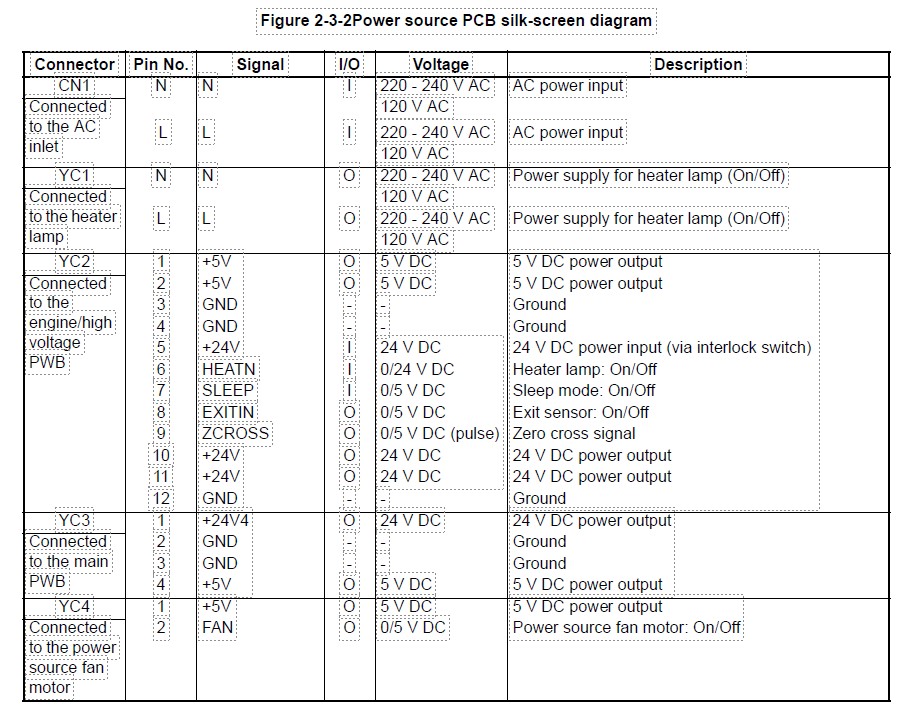
Снял плату, глянул что на ней. Цена деления 0.2V:
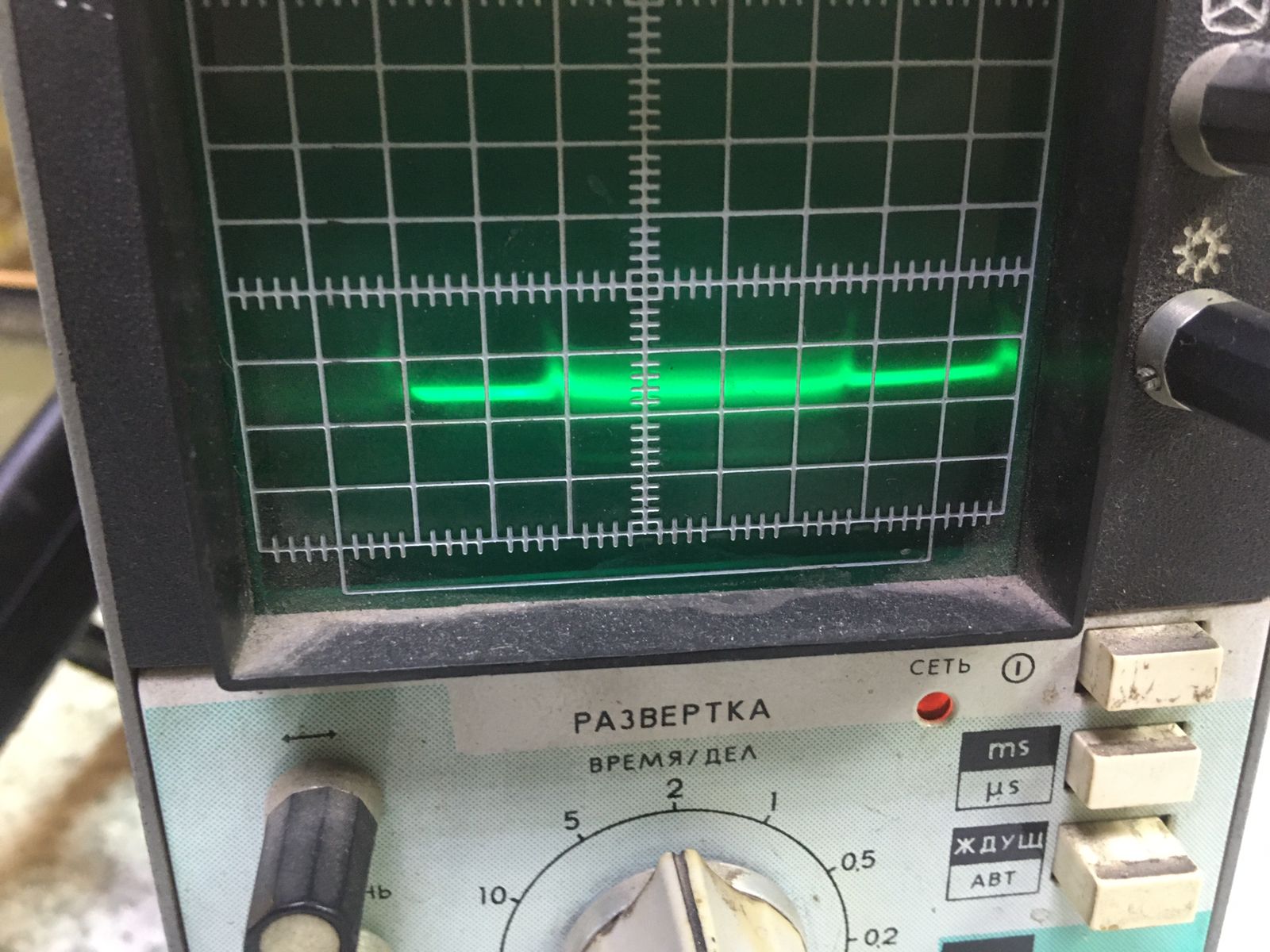
При этом на низковольтной стороне оптопары, с которой формируется этот сигнал:
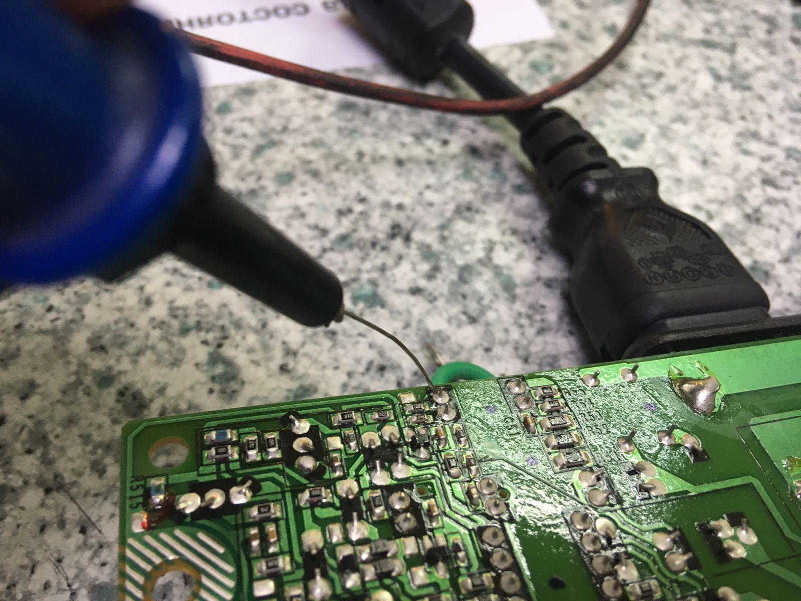
Вот такой сигнал:
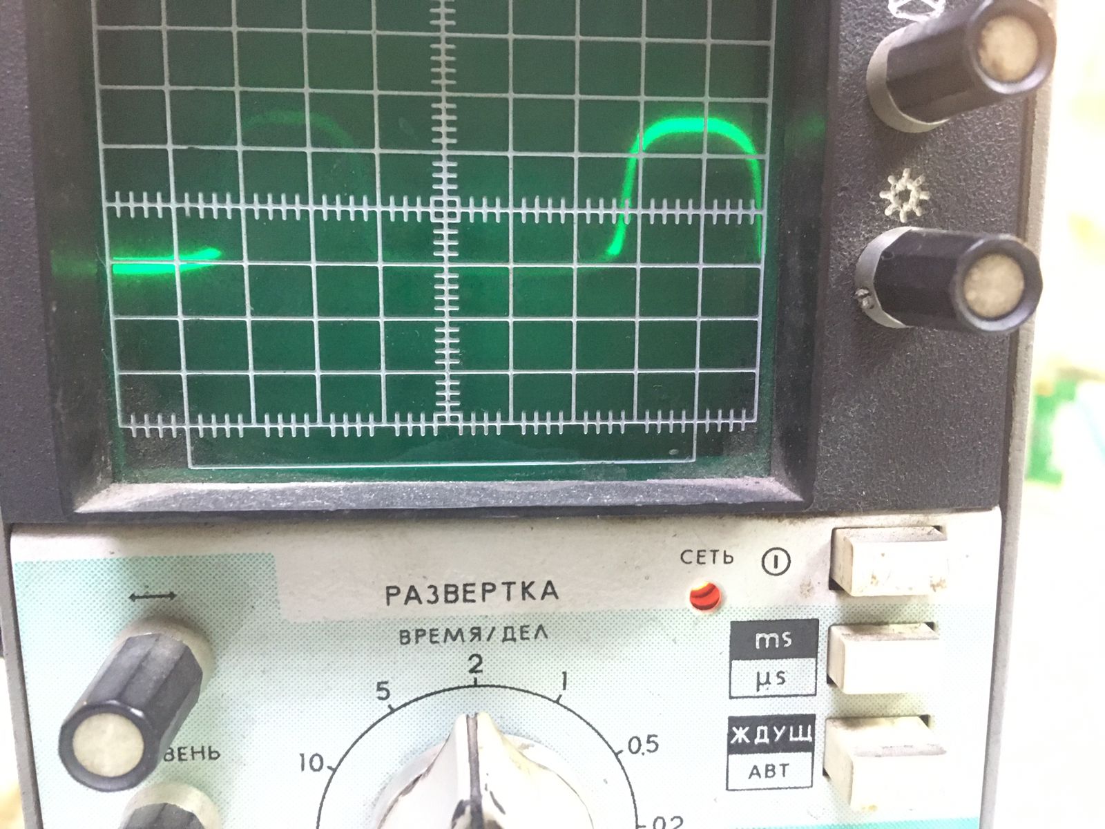
Сигнал на 9-ую ногу идет с этого транзистора:
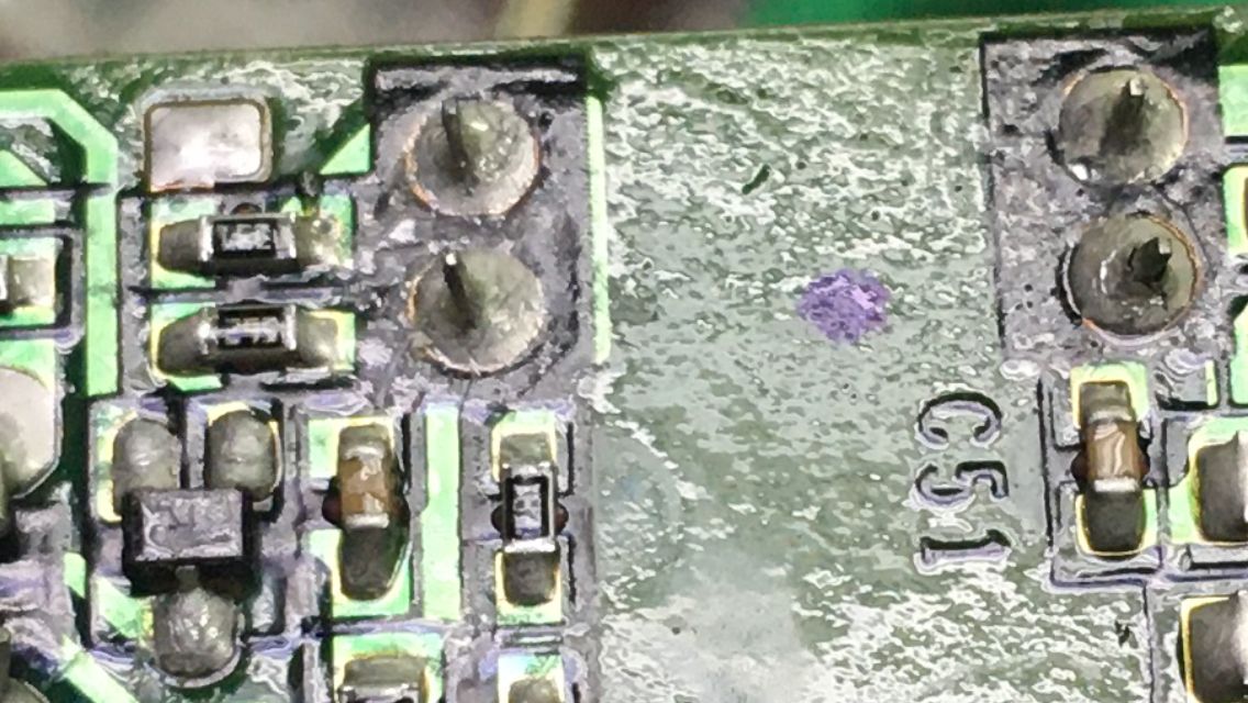
Он дохлый?
Отправлено спустя 10 минут 11 секунд:
Нифига. Просто у коллектора этого транзистора подпор к плюсу через резистор, который на другой плате, с которой плата БП соединяется этим разъемом.
-
9999
- Сообщения: 664
- Стаж: 1 год 4 месяца
- Благодарил (а): 14 раз
- Поблагодарили: 36 раз
-
Репутация:
Kyocera fs-1016MFP ошибка 6400
Сообщение
9999 » 18 апр 2023, 12:39
Ничего больше не делал.
Сегодня собрал. Он заработал как часики. Вероятно где-то был неконтакт и после разборки-сборки он самоустранился. Уже пачку тестовых листов прокатил и раз 50 включал-выключал. Как часы.
-
9999
- Сообщения: 664
- Стаж: 1 год 4 месяца
- Благодарил (а): 14 раз
- Поблагодарили: 36 раз
-
Репутация:
Kyocera fs-1016MFP ошибка 6400
Сообщение
9999 » 18 апр 2023, 13:58
serg-serg писал(а): ↑18 апр 2023, 13:19
Вот жеж. Да уж.
Но судя по тому, как народ менял БП и не помогало причина где-то на второй плате рядом с БП или в разъеме между ними. Просто не располагаю таким количеством свободного времени для изыскательских работ, а так-то да, можно было и дальше посмотреть где теряется/игнорируется сигнал.
Кстати, электрической принципиальной схемы этой платы ни у кого нет?
-
- 12 Ответы
- 1242 Просмотры
-
Последнее сообщение

09 фев 2022, 10:10
-
- 6 Ответы
- 2884 Просмотры
-
Последнее сообщение

02 фев 2022, 11:07
-
- 4 Ответы
- 1010 Просмотры
-
Последнее сообщение

16 май 2022, 10:09
-
- 4 Ответы
- 672 Просмотры
-
Последнее сообщение

16 май 2022, 14:33
-
- 20 Ответы
- 1500 Просмотры
-
Последнее сообщение
11 июл 2022, 16:08