
We have multiple applications developed in Visual Foxpro 8.0 running in a data center on Windows 2008 R2 on VMware. We also have a Citrix farm on the same network where users run yet another VFP 8.0 application in Citrix
sessions. All applications share the same set of data tables located on a file server (also Windows 2008 R2 VM). Virtual hosts are connected by 10Gb LAN (managed switch).
Since <g class=»gr_ gr_88 gr-alert gr_gramm gr_inline_cards gr_run_anim Punctuation only-ins replaceWithoutSep» data-gr-id=»88″ id=»88″>mid-July</g> we started seeing random 1104 «Error
reading file…» errors on multiple different applications on multiple servers. All of them reference different files on the file server.
The problem started mid-July and it frequency gradually increased. Earlier it was most frequent in the afternoons by 3 pm, now it happens from early morning till late afternoon. It affects EDI servers (these run batch jobs
in unattended mode) and Citrix servers and a variety of applications. It occurs when a VFP application (any of them) tries to open a database container file or individual tables most often with USE command but some times executing a SQL Select statement, or
when loading a VFP form that opens tables in DataEnvironment
We caught a moment when the same exact error happened on two different servers running different applications at the same exact moment (up to a second). We also saw two different applications running on the same computer erroring
out at the same moment.
We replaced the file server with a new virtual machine with no relief (we since changed it back to the old file server ).
We disabled the antivirus.
We updated VMware on all hosts to the latest version.
Sysinternals Process Monitor displays «INVALID_NETWORK_RESPONSE» event when the error occurs.
We captured traffic on both the server side and client side when the error occurred and had it analyzed by a network analysis specialist. He observed a peculiar pattern, where client OS starts retrieving the file in question
from the file server AFTER VFP application had thrown an error. It seems that VFP application requests a file from OS, then it either gets an abnormal response or just times out and only after that the OS sends packets requesting the file. Again, this happens
sporadically.
OpLocks and SMB2 have been disabled on all computers both on the server and client side of the equation for many years and everything was running smoothly until now…
Any advice would be greatly appreciated.
-
Edited by
Tuesday, August 22, 2017 9:38 PM
Содержание
- Обнаружена ошибка протокола на клиентском компьютере код 0x1104 сессия будет отключена
- Обнаружена ошибка протокола на клиентском компьютере код 0x1104 сессия будет отключена
- Обнаружена ошибка протокола на клиентском компьютере код 0x1104 сессия будет отключена
- Обнаружена ошибка протокола на клиентском компьютере код 0x1104 сессия будет отключена
- Открываем командную строку из интерфейса Metro UI
- Запуск командной строки из проводника
- Запуск командной строки из диспетчера задач
- Запуск из меню быстрого доступа Win+X
- Повышение привилегий открытого окна командной строки
- Открытие окна команд с правами администратора из файловых менеджеров
- Открытие окна команд с правами администратора из Проводника
- Открытие окна команд с правами администратора из Total Commander
- Открытие окна команд с правами администратора из Far
- Ключи командной строки ELE
- Причины ошибки хранимая на этом компьютере, была изменена
- Как исправить код ошибки удаленного рабочего стола 0x204 на Mac?
- Способ 1. Включите протокол удаленного рабочего стола (на компьютере с Windows)
- Способ 2. Разрешение удаленной удаленной остановки через брандмауэр Windows
- Способ 3: отключение вашего стороннего AV (если применимо)
- Способ 4: удаление стороннего брандмауэра (если применимо)
- Метод 5: Использование приглашения удаленного помощника
- Способ 6: удаление временной папки Remote Dekstop (только для MAC)
- Обнаружена ошибка протокола на клиентском компьютере код 0x1104 сессия будет отключена
Обнаружена ошибка протокола на клиентском компьютере код 0x1104 сессия будет отключена
Сообщения: 28
Благодарности: 1
 Профиль | Отправить PM | Цитировать
Доброго времени суток.
Имеется компьютер под управлением Windows 7 Home Premium х64. С него надо подключаться к терминалу Windows Server 2008 R2. При подключении вылетает ошибка: «Обнаружена ошибка протокола на клиентском компьютере (код 0х1104), сессия будет отключена.» При этом подключение к терминалу второго сервера, под управлением Windows Server 2003, проходит нормально. По внутреннему IP-адресу сервера подключение есть.
Сообщения: 28
Благодарности: 1
——-
С точки зрения физики световой меч является психически нездоровым людям
» width=»100%» style=»BORDER-RIGHT: #719bd9 1px solid; BORDER-LEFT: #719bd9 1px solid; BORDER-BOTTOM: #719bd9 1px solid» cellpadding=»6″ cellspacing=»0″ border=»0″> Источник
Обнаружена ошибка протокола на клиентском компьютере код 0x1104 сессия будет отключена
Сообщения: 28
Благодарности: 1
Профиль | Отправить PM | Цитировать
Доброго времени суток.
Имеется компьютер под управлением Windows 7 Home Premium х64. С него надо подключаться к терминалу Windows Server 2008 R2. При подключении вылетает ошибка: «Обнаружена ошибка протокола на клиентском компьютере (код 0х1104), сессия будет отключена.» При этом подключение к терминалу второго сервера, под управлением Windows Server 2003, проходит нормально. По внутреннему IP-адресу сервера подключение есть.
Сообщения: 28
Благодарности: 1
——-
С точки зрения физики световой меч является психически нездоровым людям
» width=»100%» style=»BORDER-RIGHT: #719bd9 1px solid; BORDER-LEFT: #719bd9 1px solid; BORDER-BOTTOM: #719bd9 1px solid» cellpadding=»6″ cellspacing=»0″ border=»0″> Источник
Обнаружена ошибка протокола на клиентском компьютере код 0x1104 сессия будет отключена
По непонятным причинам терминальный клиент работающий много лет вдруг, совершенно внезапно, не мог соединиться с терминальным сервером по загадочной причине отсутствия клиентской лицензии. На чешском (я столкнулся с этим у одного из клиентов именно на чешской версии windows) эта ошибка звучит так:
”Vzdálený počítač přerušil spojení z důvodu chyby v licenčním protokolu. Pokuste se připojit ke vzdálenému počítači znovu nebo se obraťte na správce serveru.” На русском:
”Удаленный компьютер отключил сеанс из-за ошибки в протоколе лицензирования. Попытайтесь подключиться к удаленному компьютеру снова или обратитесь к администратору сервера.” На английском:
”The remote computer disconnected the session because of an error in the licensing protocol. Please try connecting to the remote computer again or contact your server administrator.” При этом
ПОМНИТЕ ЧТО РАБОТА С РЕЕСТРОМ МОЖЕТ ПРИВЕСТИ К ОТКАЗУ ОПЕРАЦИОННОЙ СИСТЕМЫ ИЛИ ПРОГРАММ.
Ведите себя в редакторе реестра очень аккуратно и предельно внимательно.
И в заключении привожу немного картинок для тех кто хочет знать, что понял всё верно. Но надписи на скриншотах только на чешском, сбой произошёл именно на машине с чешской версией Windows 7.
В Windows 8 запустить командную строку с помощью прав администратора можно несколькими способами:
Опишем каждый из этих способов открытия командной строки с правами админа в Win8 подробнее.
Открываем командную строку из интерфейса Metro UI
В строке «Поиск» интерфейса Windows 8 Metro UI, нужно набрать “cmd ” (или “ command prompt ”) , в результате в левой панели отобразится найденное приложение. Затем нужно щелкнуть правой кнопкой мыши по появившемуся ярлыку и в нижней части экрана появится строка с дополнительными опциями запуска. Выберите «Запуск от имени администратора» (“Run as administrator”)
Все то же самое можно выполнить, выделив найденное приложение и нажав на клавиатуре комбинацию Ctrl + Shift + Enter .
Запуск командной строки из проводника
Запуск командной строки из диспетчера задач
Запуск из меню быстрого доступа Win+X
Проект получил имя ELE. Восьмикилобайтный экзешник стал для меня панацеей в вопросе эскалации привилегий командной строки.
Повышение привилегий открытого окна командной строки
Открытие окна команд с правами администратора из файловых менеджеров
Открытие окна команд с правами администратора из Проводника
Достаточно интегрировать ELE в контекстное меню папки и фона папки (пустого, свободного от файлов пространства окна Проводника), и вы откроете командую строку от имени администратора в любой локации жесткого диска.
Твик реестра мог бы выглядеть так:
Windows Registry Editor Version 5.00
@=»cmd /c cd /d »%1» & ele /x»
Ну и, соответственно, результат:
Открытие окна команд с правами администратора из Total Commander
Просто перетащите ele. exe на тулбар этого файлового менеджера, и отредактируйте полученную кнопку, удалив путь запуска. Это необходимо, чтобы при запуске ele в качестве рабочей папки использовался путь в активной панели Total Commander.
Нажав на эту кнопку, вы откроете текущую папку в командной строке с правами администратора.
Открытие окна команд с правами администратора из Far
Ключи командной строки ELE
Краткая справка по использованию
Ele программа [параметры]
Запустить программу от имени администратора. Например, Блокнот от имени администратора:
Ele notepad. exe d:text1.txt
Причины ошибки хранимая на этом компьютере, была изменена
В большинстве случаев ошибка удаленный сеанс отключен, так как клиентская лицензия удаленного рабочего стола, хранимая на этом компьютере, была изменена, выскакивает на клиентских операционных системах, по типу Windows 10 или 8.1
Переходим в ветку реестра
И полностью удаляем весь раздел, через правый клик.
Подтверждаем удаление. После чего перезагружаем компьютер.
Как только вы перезагрузились, нажмите WIN+R и введите mstsc /admin, чтобы у вас открылось окно удаленного рабочего стола от имени администратора.
Все можем пытаться подключаться к вашему серверу терминалов.
Если не поможет, то попробуйте создать bat файл и выполнить его, ниже содержимое.
Const HKLM = &H80000002
Const MSLicensingStore = «SoftwareMicrosoftMSLicensingStore»
Set oReg = GetObject(«winmgmts:.rootdefault:StdRegProv»)
RetVal = oReg. EnumKey(HKLM, MSLicensingStore, RegKeys)
If RetVal <> 0 Then
MsgBox(«Не удалось прочитать ветвь реестра » & MSLicensingStore)
WScript. Quit
End If
If IsArray(RegKeys) Then
For Each Key In RegKeys
KeyName = MSLicensingStore & Key
If InStr(1, UCase(KeyName), «LICENSE») > 0 Then
RetVal = oReg. DeleteKey(HKLM, KeyName)
End If
Next
End If
Как исправить код ошибки удаленного рабочего стола 0x204 на Mac?
Некоторые пользователи, которые пытаются подключиться к компьютеру Windows с Mac, Android или другой ОС, получают код ошибки 0x204 при попытке использовать протокол удаленного рабочего стола. Хотя удаленный рабочий стол является надежным инструментом, позволяющим пользователям подключаться к ПК и получать доступ к приложениям, файлам и сетевым ресурсам, иногда все работает не так, как должно.
Одной из наиболее распространенных проблем, которые вызывают код ошибки 0x204, является случай, в котором протокол удаленного рабочего стола не включен на компьютере Windows. В этом случае вы можете решить проблему, включив ее вручную через экран «Свойства системы» и разрешив подключения на сетевом уровне.
Однако это также может быть вызвано вашим брандмауэром (поскольку процесс, используемый удаленным рабочим столом, эксплуатируется многими вредоносными программами). Чтобы решить эту проблему, в этом случае вам необходимо установить правило исключения, отключить защиту в режиме реального времени или вообще удалить сторонний пакет безопасности.
В некоторых случаях проблема может возникнуть из-за некоторых временных файлов, которые хранятся в папке Group Containers. Если этот сценарий применим, вы можете устранить проблему, удалив папку UBF8T346G9.com. microsoft. rdc.
Способ 1. Включите протокол удаленного рабочего стола (на компьютере с Windows)
Одной из наиболее распространенных причин, которые вызывают код ошибки 0x204 при попытке доступа к файлам из ОС Windows с использованием протокола удаленного рабочего стола, является, безусловно, случай, когда функциональность удаленного рабочего стола не включена на экране «Свойства системы».
Это должен быть ваш первый шаг по устранению неполадок, если вы попытались подключиться с использованием протокола удаленного рабочего стола, используя несколько устройств, и все они вызвали одну и ту же проблему.
Вот пошаговое руководство по включению протокола удаленного рабочего стола на компьютере Windows, с которого вы получаете доступ к файлам:
Примечание. Приведенные ниже шаги являются универсальными и должны работать независимо от версии Windows, которую вы используете на хост-компьютере.
Примечание. Когда вам будет предложено UAC (Контроль учетных записей), нажмите Да, чтобы предоставить административные привилегии.
Примечание. Если вы пытаетесь подключиться к компьютеру из другой сети, вам также необходимо снять флажок «Разрешить подключения только с компьютеров, работающих под управлением удаленного рабочего стола с проверкой подлинности на уровне сети».
Если проблема все еще не решена, перейдите к следующему потенциальному решению ниже.
Способ 2. Разрешение удаленной удаленной остановки через брандмауэр Windows
Помните, что по умолчанию брандмауэр Windows не настроен на использование протокола удаленного рабочего стола в белом списке.
Поэтому, если вы хотите использовать удаленный рабочий стол, чтобы сделать ваши файлы доступными для других компьютеров, вам нужно будет изменить настройки безопасности по умолчанию, чтобы разрешить удаленный декстоп и удаленный рабочий стол (Websocket) через меню «Разрешенные приложения» настроек брандмауэра Windows.
Это нужно делать независимо от того, какую версию Windows вы используете.
Важное замечание: Если вы используете сторонний пакет брандмауэра, приведенные ниже шаги не будут применяться. В этом случае вам нужно будет найти конкретные шаги, которые позволят вам внести в белый список протокол удаленного рабочего стола.
Вот краткое руководство о том, как разрешить протоколу удаленного рабочего стола взаимодействовать с другими устройствами в этой сети:
Примечание. Если вас попросит UAC (Контроль учетных записей), нажмите Да, чтобы предоставить административные привилегии.
Если проблема все еще не решена, и вы все еще сталкиваетесь с тем же Кодом ошибки 0x204, перейдите к следующему потенциальному исправлению ниже.
Способ 3: отключение вашего стороннего AV (если применимо)
Как выясняется, во многих случаях пользователи сталкиваются с этой проблемой при использовании сторонних пакетов безопасности. McAfee Internet Security является наиболее распространенным пакетом сторонних производителей, который, как известно, облегчает код ошибки 0x204.
Скорее всего, происходит то, что сторонние AV запускают ложное срабатывание и угрожают порту, используемому протоколом удаленного рабочего стола, как злонамеренная попытка доступа к вашим файлам на расстоянии.
В случае, если этот сценарий применим к вашей текущей ситуации, вы должны быть в состоянии исправить подразумеваемые проблемы, отключив защиту в реальном времени вашего комплекта AV сторонних производителей. Но имейте в виду, что шаги для этого зависят от того, какой AV вы используете.
Но в большинстве случаев вы сможете отключить постоянную защиту (активные щиты) прямо из меню панели задач. Для этого просто щелкните правой кнопкой мыши значок меню на панели задач и найдите параметр, который отключает защиту в режиме реального времени.
Отключение всех щитов Avast
Если вы сделали это безрезультатно или используете сторонний пакет брандмауэров, перейдите к следующему потенциальному исправлению ниже.
Способ 4: удаление стороннего брандмауэра (если применимо)
В случае, если вы используете сторонний брандмауэр, отключение или запрет его работы не будет иметь значения, так как те же наборы безопасности останутся на месте. Если проблема вызвана сторонним брандмауэром, единственный способ исправить это – создать правило белого списка, исключающее удаленный рабочий стол из списка анализируемых процессов.
Но имейте в виду, что шаги этого очень отличаются от инструмента к инструменту.
Если ваш AV не имеет возможности добавлять исключения, единственное реальное исправление – полностью удалить инструмент безопасности и убедиться, что нет оставшихся файлов, которые по-прежнему будут блокировать этот порт.
Если вы хотите выполнить этот метод, вот пошаговое руководство по удалению стороннего брандмауэра:
Если проблема сохраняется, перейдите к следующему потенциальному решению ниже.
Метод 5: Использование приглашения удаленного помощника
Оказывается, некоторые пользователи смогли решить проблему, создав автономное приглашение с помощью утилиты удаленного помощника Windows и открыв его на компьютере, который не может подключиться с помощью протокола удаленного доступа Windows.
Эта операция в конечном итоге обходит каждый потенциально заблокированный порт, который может вызывать проблему с кодом ошибки 0x204, с помощью автономного приглашения.
Вот краткое руководство по созданию приглашения на удаленную помощь:
Примечание. Если вы получите запрос от UAC (Контроль учетных записей), нажмите Да, чтобы предоставить административные привилегии.
Примечание. Вы можете выбрать другой вариант, если вам будет проще (либо прикрепите приглашение с помощью программы электронной почты, либо воспользуйтесь Easy Connect)
Если та же проблема все еще сохраняется, перейдите к следующему потенциальному решению ниже.
Способ 6: удаление временной папки Remote Dekstop (только для MAC)
Если ни один из перечисленных выше методов не сработал, и вы сталкиваетесь только с проблемой OSX, очень вероятно, что временная папка, используемая приложением Mac Remote Desktop, содержит поврежденные файлы, которые не позволяют установить соединение.
Если этот сценарий применим к вашей текущей ситуации, вы можете устранить проблему, удалив временную папку из папки контейнера группы. Вот краткое руководство о том, как это сделать:
Источник
Обнаружена ошибка протокола на клиентском компьютере код 0x1104 сессия будет отключена
Так. Думаю это поможет. Если не понятно, скажи, переведу 
This error indicates that RDP is not available to use TCP port 3389l.
Occasionally, RPC provides 3389 to another service and this does not allow
RDP to function. RPC can be isolated and confirmed if you stop the
MSExchangeSA service.
To keep this from happening in the future add the following using regedt32:
(of course, backup the registry keys before making these changes).
Add the following key if not present:
Highlight the following key:
HKEY_LOCAL_MACHINESoftwareMicrosoftRpc
From Edit menu select «Add Key. »
Key Name: Internet
Class:
Add the following values if not prestent:
Highlight the following key:
HKEY_LOCAL_MACHINESoftwareMicrosoftRpcInternet
From Edit menu select «Add Value. »
Value Name: Ports
Data Type: REG_MULTI_SZ
Data: 3389-3389
From Edit menu select «Add Value. »
Value Name: PortsInternetAvailable
Data Type: REG_SZ
Data: N
From Edit menu select «Add Value. »
Value Name: UseInternetPorts
Data Type: REG_SZ
Data: Y
Then reboot the server and try again.
Короче, для начала останови сервиc MSExchangeSA, и попробуй подключитса.
Источник
Adblock
detector
На нашем ресурсе имеется возможность задавать вопросы и делиться собственным опытом по устренению неисправностей связанных с ошибкой C1104. Задав вопрос в течении нескольких дней Вы сможете найти ответ на него.
Принимая во внимание тот факт, что OBD2 ошибки работы двигателя или других электронных систем автомобиля не всегда на прямую указывают на неработающий элемент, и то что разных марках и моделях автомобилей одна и таже ошибка может возникать как следствие неисправности абсолютно разных элементов электронной системы мы создали этот алгоритм помощи и обмена полезной информацией.
Мы надеемся, с Вашей помощью, сформировать причино-следственную связь возникновения той или иной OBD2 ошибки у конкретного автомобиля (марка и модель). Как показал опыт если рассматривать определенную марка-модель автомобиля, то в подавляющем большинстве случаев причина ошибки одна и таже.
Если ошибка указывает на неверные параметры (высокие или низкие значения) какого нибудь из датчиков или анализаторов, то вероятней всего этот элемент исправен, а проблему надо искать так сказать «выше по течению», в элементах работу которых анализирует датчик или зонд.
Если ошибка указывает на постоянно открытый или закрытый клапан, то тут надо подойти к решению вопроса с умом, а не менять бездумно этот элемент. Причин может быть несколько: клапан засорен, клапан заклинил, на клапан приходит неверный сигнал от других неисправных узлов.
Ошибки работы двигателя OBD2 и других систем автомобиля (ELM327) не всегда на прямую указывают на неработающий элемент. Сама по себе ошибка является косвенными данными о неисправности в системе, в некотором смысле подсказкой, и только в редких случаях прямым указанием на неисправный элемент, датчик или деталь. Ошибки (коды ошибок) полученные от прибора, сканера требуют правильной интерпретации информации, дабы не тратить время и деньги на замену работающих элементов автомобиля. Проблема зачастую кроется намного глубже чем кажется на первый взгляд. Это вызвано теми обстоятельствами, что информационные сообщения содержат, как было выше сказано, косвенную информацию о шарушении работы системы.
Вот пару общих примеров. Если ошибка указывает на неверные параметры (высокие или низкие значения) какого нибудь из датчиков или анализаторов, то вероятней всего этот элемент исправен, так как он анализирует (выдает некие параметры или значения), а проблему надо искать так сказать «выше по течению», в элементах работу которых анализирует датчик или зонд.
Если ошибка указывает на постоянно открытый или закрытый клапан, то тут надо подойти к решению вопроса с умом, а не менять бездумно этот элемент. Причин может быть несколько: клапан засорен, клапан заклинил, на клапан приходит неверный сигнал от других неисправных узлов.
Еще один момент который хотелось бы отметить — это специфика той или иной марки и модели. Поэтому узнав ошибку работы двигателя или дрогой системы Вашего автомобиля не спешите делать поспешных решений, а подойдите к вопросу комплексно.
Наш форум создан для всех пользователей, от простых автолюбителей до профессиональных автоэлектриков. По капле от каждого и всем будет полезно.
Содержание
- 0x1104 error remote desktop windows 10
- Произошла ошибка проверки подлинности. Указанная функция не поддерживается
- Ответ
- Отключение NLA для протокола RDP в Windows
- 0x1104 Remote Desktop Windows 7 — remote desktop stopped working, how do I fix it?
- 0x1104 error remote desktop windows 10
- Вопрос
- Все ответы
- To allow Remote Desktop connections through a Windows Firewall
- Ошибка RDP подключения: Указанная функция не поддерживается, ошибка шифрования CredSSP
0x1104 error remote desktop windows 10
Сообщения: 28
Благодарности: 1
Профиль | Отправить PM | Цитировать
Доброго времени суток.
Имеется компьютер под управлением Windows 7 Home Premium х64. С него надо подключаться к терминалу Windows Server 2008 R2. При подключении вылетает ошибка: «Обнаружена ошибка протокола на клиентском компьютере (код 0х1104), сессия будет отключена.» При этом подключение к терминалу второго сервера, под управлением Windows Server 2003, проходит нормально. По внутреннему IP-адресу сервера подключение есть.
Если же вы забыли свой пароль на форуме, то воспользуйтесь данной ссылкой для восстановления пароля.
| Конфигурация компьютера | |
| Материнская плата: Asus P5K-VM | |
| HDD: Seagate Barracuda 7200.10 320GB sATAII | |
| Звук: HDA кодек Realtek ALC883 | |
| CD/DVD: SonyNEC Optiarc AD-7203S | |
| ОС: Windows 7 Ultimate 32-bit | |
» width=»100%» style=»BORDER-RIGHT: #719bd9 1px solid; BORDER-LEFT: #719bd9 1px solid; BORDER-BOTTOM: #719bd9 1px solid» cellpadding=»6″ cellspacing=»0″ border=»0″>
Сообщения: 1
Благодарности: 0
Произошла ошибка проверки подлинности. Указанная функция не поддерживается
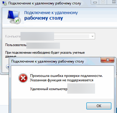
После установки обновления KB4103718 на моем компьютере с Windows 7 я не могу удаленно подключится к серверу c Windows Server 2012 R2 через удаленный рабочий стол RDP. После того, как я указываю адрес RDP сервера в окне клиента mstsc.exe и нажимаю «Подключить», появляется ошибка:
Произошла ошибка проверки подлинности.
Указанная функция не поддерживается.
Удаленный компьютер: computername
После того, как я удалил обновление KB4103718 и перезагрузил компьютер, RDP подключение стало работать нормально. Если я правильно понимаю, это только временное обходное решение, в следующем месяце приедет новый кумулятивный пакет обновлений и ошибка вернется? Можете что-нибудь посоветовать?
Ответ
Вы абсолютно правы в том, что бессмысленно решать проблему удалением обновлений Windows, ведь вы тем самым подвергаете свой компьютер риску эксплуатации различных уязвимостей, которые закрывают патчи в данном обновлении.
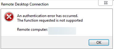
В своей проблеме вы не одиноки. Данная ошибка может появится в любой операционной системе Windows или Windows Server (не только Windows 7). У пользователей английской версии Windows 10 при попытке подключится к RDP/RDS серверу аналогичная ошибка выглядит так:
The function requested is not supported.
Remote computer: computername
Ошибка RDP “An authentication error has occurred” может появляться и при попытке запуска RemoteApp приложений.
Почему это происходит? Дело в том, что на вашем компьютере установлены актуальные обновления безопасности (выпущенные после мая 2018 года), в которых исправляется серьёзная уязвимость в протоколе CredSSP (Credential Security Support Provider), использующегося для аутентификации на RDP серверах (CVE-2018-0886) (рекомендую познакомится со статьей Ошибка RDP подключения: CredSSP encryption oracle remediation). При этом на стороне RDP / RDS сервера, к которому вы подключаетесь со своего компьютера, эти обновления не установлены и при этом для RDP доступа включен протокол NLA (Network Level Authentication / Проверку подлинности на уровне сети). Протокол NLA использует механизмы CredSSP для пре-аутентификация пользователей через TLS/SSL или Kerberos. Ваш компьютер из-за новых настроек безопасности, которые выставило установленное у вас обновление, просто блокирует подключение к удаленному компьютеру, который использует уязвимую версию CredSSP.
Что можно сделать для исправления эту ошибки и подключиться к вашему RDP серверу?
- Самый правильный способ решения проблемы – установка последних кумулятивных обновлений безопасности Windows на компьютере / сервере, к которому вы подключаетесь по RDP;
- Временный способ 1 . Можно отключить проверку подлинности на уровне сети (NLA) на стороне RDP сервера (описано ниже);
- Временный способ 2 . Вы можете на стороне клиента разрешить подключение к RDP серверам с небезопасной версией CredSSP, как описано в статье по ссылке выше. Для этого нужно изменить ключ реестра AllowEncryptionOracle (команда REG ADD
HKLMSOFTWAREMicrosoftWindowsCurrentVersionPoliciesSystemCredSSPParameters /v AllowEncryptionOracle /t REG_DWORD /d 2 ) или изменить настройки локальной политики Encryption Oracle Remediation / Исправление уязвимости шифрующего оракула), установив ее значение = Vulnerable / Оставить уязвимость).
Отключение NLA для протокола RDP в Windows
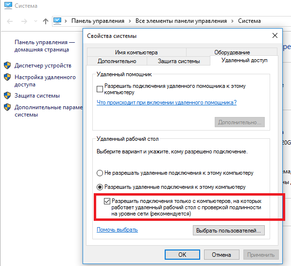
Если на стороне RDP сервера, которому вы подключаетесь, включен NLA, это означает что для преаутентификации RDP пользователя используется CredSPP. Отключить Network Level Authentication можно в свойствах системы на вкладке Удаленный доступ (Remote), сняв галку «Разрешить подключения только с компьютеров, на которых работает удаленный рабочий стол с проверкой подлинности на уровне сети / Allow connection only from computers running Remote Desktop with Network Level Authentication (recommended)» (Windows 10 / Windows 8).
В Windows 7 эта опция называется по-другому. На вкладке Удаленный доступ нужно выбрать опцию «Разрешить подключения от компьютеров с любой версией удаленного рабочего стола (опасный) / Allow connections from computers running any version of Remote Desktop (less secure)».
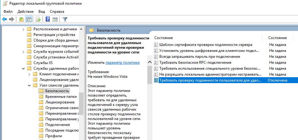
Также можно отключить проверку подлинности на уровне сети (NLA) с помощью редактора локальной групповой политики — gpedit.msc (в Windows 10 Home редактор политик gpedit.msc можно запустить так) или с помощью консоли управления доменными политиками – GPMC.msc. Для этого перейдите в разделе Конфигурация компьютера –> Административные шаблоны –> Компоненты Windows –> Службы удаленных рабочих столов – Узел сеансов удаленных рабочих столов –> Безопасность (Computer Configuration –> Administrative Templates –> Windows Components –> Remote Desktop Services – Remote Desktop Session Host –> Security), отключите политику Требовать проверку подлинности пользователя для удаленных подключений путем проверки подлинности на уровне сети (Require user authentication for remote connections by using Network Level Authentication).
Также нужно в политике «Требовать использования специального уровня безопасности для удаленных подключений по протоколу RDP» (Require use of specific security layer for remote (RDP) connections) выбрать уровень безопасности (Security Layer) — RDP.
Для применения новых настроек RDP нужно обновить политики (gpupdate /force) или перезагрузить компьютер. После этого вы должны успешно подключиться к удаленному рабочему столу сервера.
0x1104 Remote Desktop Windows 7 — remote desktop stopped working, how do I fix it?
Hi, I realize that there’s another forum post to this effect, which Oberwald locked, where s/he suggests that I should just roll back all the security updates that Microsoft puts out, in order to fix this problem . but does anyone know a way to fix this without the ‘System Restore Point’ methodology?
I’ve tried the registry edits I was able to find (though others might be appreciated), and disabled the Norton firewalls, etc . any other things?
It’s Windows 7 Professional (client) to Windows 7 Ultimate (host).
What was the recent hardware and software change made to the computer before the issue started?
The reason you may be receiving this error might be due to a protocol error of conflicting Visual styles between the computers having Remote Desktop Connection.
On the remote computer you will have to find a compatible visual style that works with RDP in case of a custom style set or conflict.
Please try un checking the option Visual Styles and check if you are able to use the Remote Desktop Connection.
a. Click Start
b. Launch Remote Desktop Connection (RDP)
c. Click on Options on the RDP window
d. Click on the Experience tab
e. Uncheck the Visual Styles option
f. Try starting the RDP process and check if you are able to connect.
You may also refer to the following links,
Why can’t I connect using Remote Desktop Connection?
Hope this helps.
13 people found this reply helpful
Was this reply helpful?
Sorry this didn’t help.
Great! Thanks for your feedback.
How satisfied are you with this reply?
Thanks for your feedback, it helps us improve the site.
0x1104 error remote desktop windows 10
![]()
Вопрос
![]()
![]()
When i try to connect to my other pc through lan it works fine, but through internet from my phone or pc, i get error 1104
port is open, tried switching to a different port. Works through lan.
Все ответы
![]()
![]()
Please try to launch the RDP via type mstsc /Admin in the Run box, and then make sure the configuration is below:
Meanwhile, disable all of your security software include firewall. It might be because Firewall block the RDP port.
To allow Remote Desktop connections through a Windows Firewall
If you’re having trouble connecting, Remote Desktop connections might be getting blocked by the firewall. Here’s how to change that setting on a Windows PC. If you’re using another firewall, make sure the port for Remote Desktop (usually 3389) is open.
- On the remote computer, click Start and select Control Panel .
- Click System and Security.
- Click Allow a program through Windows Firewall under Windows Firewall.
- Click Change settings and then check the box next to Remote Desktop .
- Click OK to save the changes.
Ошибка RDP подключения: Указанная функция не поддерживается, ошибка шифрования CredSSP
После установки последних обновлений безопасности, вышедших 8 мая 2018 года, на Windows 10 и 7, пользователи стали жаловаться, что при попытке подключится к RemoteApp на RDS серверах под Windows Server 2016 / 2012 R2 / 2008 R2, или удаленным рабочим столам других пользователей по протоколу RDP (на Win 10/8/7), появляется ошибка:
Remote Desktop connection
An authentication error has occurred.
The function is not supported.
Remote Computer: hostname
This could be due to CredSSP encryption oracle remediation.
Подключение к удаленному рабочему столу
Произошла ошибка при проверке подлинности.
Указанная функция не поддерживается.
Причиной ошибки может быть исправление шифрования CredSSP.
Данная ошибка связана с тем, что на Windows Server или обычных десктопных версиях Windows, к котором вы пытаетесь подключится по RDP, с марта 2018 года не устанавливались обновления безопасности. Дело в том, что еще в марте 2018 Microsoft выпустила обновление, закрывающее возможность удаленного выполнения кода с помощью уязвимости в протоколе CredSSP (бюллетень CVE-2018-0886). В мае 2018 было опубликовано дополнительное обновление, в котором по-умолчанию клиентам запрещается подключаться к удаленным RDP серверам с уязвимой (непропатченной) версией протокола CredSSP.
Таким образом, если вы не устанавливали накопительные обновления безопасности на RDS серверах Windows с марта этого года, а клиенты (Win 10 / 8 / 7) установили майские обновления, то на них при попытке подключится к RDS серверам с непропатченной версией CredSSP будет появляется ошибка о невозможности подключения: This could be due to CredSSP encryption oracle remediation.
Ошибка RDP клиента появляется после установки следующих обновлений безопасности:
- Windows 7 / Windows Server 2008 R2 — KB4103718
- Windows 8.1 / Windows Server 2012 R2 — KB4103725
- Windows Server 2016 — KB4103723
- Windows 10 1803 — KB4103721
- Windows 10 1709 — KB4103727
- Windows 10 1703 — KB4103731
- Windows 10 1609 — KB4103723
Для восстановления удаленного подключения к рабочему столу можно удалить указанное обновление (но это не рекомендуется и делать этого не стоит, есть более правильное решение).
Для решения проблемы нужно временно на компьютере, с которого вы подключаетесь по RDP, убрать данное уведомление безопасности, блокирующее подключение.
Это можно сделать через редактор локальных групповых политик. Для этого:
- Запустите редактор локальных GPO: gpedit.msc ;
В том случае, если у вас отсутствует редактор локальных GPO (например, в Home редакциях Windows), вы можете внести изменение, разрешающее RDP подключение к серверам с непропатченной версия CredSSP, напрямую в реестр с помощью команды:
REG ADD HKLMSOFTWAREMicrosoftWindowsCurrentVersionPoliciesSystemCredSSPParameters /v AllowEncryptionOracle /t REG_DWORD /d 2
Можно внести изменения сразу на множестве компьютеров в AD с помощью доменной GPO или такого PowerShell скрипта (список компьютеров в домене можно получить с помощью командлета Get-ADComputer ):
Import-Module ActiveDirectory
$PSs = (Get-ADComputer -Filter *).DNSHostName
Foreach ($computer in $PCs) <
Invoke-Command -ComputerName $computer -ScriptBlock <
REG ADD HKLMSOFTWAREMicrosoftWindowsCurrentVersionPoliciesSystemCredSSPParameters /v AllowEncryptionOracle /t REG_DWORD /d 2
>
>
После успешного подключения к удаленному RDP серверу (компьютеру) нужно установить на нем отсутствующие обновления безопасности через службу Windows Update (проверьте, что служба включена) или вручную. Ниже представлены прямые ссылки на обновления для Windows Server, которые обязательно нужно установить:
- Windows Server 2012 R2 / Windows 8: KB4103715
- Windows Server 2008 R2 / Windows 7: KB4103712
- Windows Server 2016 / Windows 10 1607 = KB4103723
После установки обновлений и перезагрузки сервера, не забудьте отключить политику на клиентах (либо выставить ее на Force Updated Clients), или вернуть значение 0 у ключа реестра AllowEncryptionOracle. В этом случае, ваш компьютер не будет подвержен риску подключения к незащищенным хостам с CredSSP и эксплуатации уязвимости.
REG ADD HKLMSOFTWAREMicrosoftWindowsCurrentVersionPoliciesSystemCredSSPParameters /v AllowEncryptionOracle /t REG_DWORD /d 0
Adblock
detector
Code
Display
1101
Error: Host name
1102
Error: User/Password
1104
Error: No Recipient address The destination address is not
1105
Error: Not support protocol
1106
Error: No Sender Info
2101
Error: Can not connect
2102
Error: Can not connect with
timeout
2103
Error: Response wait with
timeout
2201
Error: Network transfer
2202
Error: Network transfer with
timeout
2203
Error: Response wait with
timeout
2204
Error: E-Mail Size limit
3101
Error: Server response
3201
Error: Not Found Authenti-
cation Mechanism
9181
Error: Page max count over
Causes
SMTP sever name is not set.
Error SMTP server name.
User ID for the authentication
is not entered or entered
wrongly.
Wrong authentication pass-
word is entered.
specified.
SMTP Protocol is set to OFF.
Sender address is not enter
Select [Other authenticate]
when authenticating POP
before SMTP.
The specified server is not
SMTP server.
Network is not connected.
The server is unable to com-
municate.
The server is unable to com-
municate.
Error occurs on the network.
Error occurs on the network.
Response is not returned
from the server above speci-
fied time.
The size of E-mail exceeds its
limit.
The server is error status.
Server setting is not authenti-
cated normally.
Unsupported SMTP Authenti-
cation Mechanism is found.
The number of pages of a
send file exceeded 999
pages.
Remarks
Check procedures/corrective measures
Register [SMTP Server Name] in
[Advanced]-[SMTP] -[General] in
COMMAND CENTER.
Enter the correct user ID/password for
authentication at [Advance] in COMMAND
CENTER.
Enter the password of [Login User Name] of
the [POP3] page or the [SMTP] page cor-
rectly.
Specify the destination address.
Check ON [SMTP] in [Advanced]-[SMTP] —
[General] in COMMAND CENTER.
Enter the correct [Sender Address] in
[Advanced]-[SMTP] -[General] in
COMMAND CENTER.
Select valid POP3 user other than [Other].
Enter the correct [SMTP Server Name] in
[Advanced]-[SMTP] -[General] in
COMMAND CENTER.
Check if the server is operating properly.
Check the network connection (cable. net-
work condition within LAN, etc.).
Check if the server is operating properly.
Check if the server is operating properly.
Check the network connection (cable. net-
work condition within LAN, etc.).
Check the network connection (cable. net-
work condition within LAN, etc.).
Check the network connection (cable. net-
work condition within LAN, etc.).
Change the [E-mail Size Limit] in
[Advanced]-[SMTP] -[General]-[E-mail Set-
ting] in COMMAND CENTER.
Check if the server is working properly.
Check the settings for client/server authenti-
cation.
Check the settings for client/server Authenti-
cation Mechanism.
Set the number of pages as 999 or less.
2JN
1-4-33
![]()
Kyocera. 1102 ошибка
Перевод описания ошибки из сервисного руководства:
1102. Подсоединение к компьютеру не удалось:
- Подтвердите имя пользователя и пароль.
- Проверьте правильность параметров сети, к которой подключено устройство.
- Проверьте компьютер, если папка правильно размещена.
1102 ошибка может возникать при:
- Передаче через SMB‐сервер. Проверьте параметры настройки SMB:
- имя пользователя и пароль при входе;
Примечание: Если отправитель является пользователем домена, укажите имя домена.
- имя хоста;
- путь.
- Передаче электронного письма. Проверьте следующие настройки в COMMAND CENTER:
- имя пользователя и пароль для сервера SMTP;
- имя пользователя и пароль для сервера POP3.
- Передаче через FTP‐сервер. Проверьте параметры настройки FTP‐сервера:
- имя пользователя и пароль при входе;
Примечание: Если отправитель является пользователем домена, укажите имя домена.
- путь;
- право доступа получателя к папке.
Распространённые ошибки настройки: скорее всего, вы ввели короткий логин для доступа к папке вместо полного. Полный логин содержит имя домена (для доменной учётной записи), например: DOMAINUserLogin. (Для локального пользователя — просто UserLogin.) Если это условие выполнено, но ошибка появляется, проверьте настройки сетевого экрана (в качестве быстрой проверки (не рекомендуется) можно временно его полностью отключить). Также проверьте путь к папке сканирования (он должен быть максимально коротким (не более двух слешей).
Причины сбоев и ошибок:
- Постоянная или временная недоступность настроенного сетевого ресурса.
- Ограничение на допустимое количество символов в имени компьютера, имени пользователя и пароле — не более 64. Путь к сетевой папке не должен содержать более 128 символов.
- Ошибка 1102 может возникать при использовании короткого логина вместо полного («имя домена имя пользователя (без кавычек и пробелов около косой черты).
- Неверный путь к сетевой папке. Например, указан локальный путь, а не сетевой.
- Если все сохраненные значения параметров верны, а при попытке сканирования возникает ошибка, проверьте настройки сетевого экрана (firewall’а — ‘брандмауэра’), возможно, что в сетевых правилах существует запись с более высоким приоритетом, блокирующая порт.
 Чтобы избежать ситуаций с возникновением ошибок, необходимо изначально правильно настроить оборудование.
Настройка компьютера:
- Проверьте сетевое полное имя компьютера (хоста), домен и имя пользователя и запишите значения. Пользователи Windows в командной строке могут набрать net config workstation либо получить нужные значения через «Свойства системы.
- Создайте сетевую папку и настройте права доступа в ней. В общей папке можно создать подпапку в качестве расположения для передачи данных. В этом случае в поле «Путь нужно ввести «Имя общей папки Имя подпапки (без кавычек и пробелов около косой черты).
- Включите общий доступ для файлов и принтеров и (если необходимо) настройте правило для входящих подключений: 139 порт по протоколу TCP. 139 — порт по умолчанию, но он может быть изменен (см. Руководство пользователя).
Настройка МФУ:
-
- Убедитесь, что в COMMAND CENTER включены протоколы SMB и FTP (подробная информация изложена в руководстве пользователя, в том числе правило ввода символов).
- Положите оригинал на стекло, нажмите клавишу «Отправить.
- Выберите направление передачи: папка SMB или папка FTP.
- Введите имя компьютера.
- Введите имя папки, заданное в параметрах общего доступа.
- Введите имя и пароль пользователя, которые используются для входа в компьютер с папкой общего доступа.
- В случае удачной проверки нажмите «Подтвердить адресат и клавишу «Старт.
Примечание: При внесении неправильных данных могут возникать ошибки с кодами 1102, 1103 и 3101 при проблемах с FTP‐сервером.
Kyocera. Ошибка 1103
Может быть при сканировании может появиться при:
- Передаче через SMB‐сервер. Проверьте параметры настройки SMB:
- имя пользователя и пароль при входе;
Примечание: Если отправитель является пользователем домена, укажите имя домена.
- путь;
- право доступа получателя к папке.
- Передаче через FTP‐сервер. Проверьте параметры настройки FTP‐сервера:
- путь;
- право доступа получателя к папке.
Ошибка 1105 Kyocera
может быть при:
- Передаче через SMB‐сервер. Проверьте следующие настройки в COMMAND CENTER:
- задайте значение «Вкл. для настроек SMB‐сервера.
- Передаче электронного письма. Проверьте следующие настройки в COMMAND CENTER:
- задайте значение «Вкл. для настроек SMTP‐сервера.
- Передаче через FTP‐сервер. Проверьте следующие настройки в COMMAND CENTER:
- задайте значение «Вкл. для настроек FTP‐сервера.
Below is a long list of Kyocera error codes. Some Kyocera printers can be reset by turning the machine power switch off and back on while some others activate “partial operation control” disabling the defective part/area of the machine (paper feed cassette, stapler, document processor etc). If a specific unit is not working, perform U906 after taking measures against the cause of trouble to reactivate the unit.
Error Code
Description
C0030
Fax PWB Problem. Processing with fax software is disabled due to software or hardware issues.
C0060
Main PWB Type Mismatch Error.
C0070
Fax PWB Incompatability Detection Problem. Fax software is not compatible with main PWB software.
C0130
Main PWB EEPROM Backup Memory Device Problem. EEPROM can not be written or read.
C0140
Main PWB EEPROM Backup Memory Data Problem. Abnormal reading data from EEPROM.
C0150
Engine PWB EEPROM Backup Memory Device Problem. EEPROM cannot be written or read.
C0160
Engine PWB EEPROM Backup Memory Data Problem. Abnormal reading data from EEPROM. Read & write data do not match five times consecutively.
C0170
Copy Counts Problem. A checksum error is detected in the main and engine backup memories for copy counters.
C0180
Machine Number Mismatch Error. Machine number does not match on main and engine PWBs
C0600
Main PWB DIMM Installed Incorrectly.
C0610
Main PWB DIMM error
C0630
DMA transmission of compressed, decompressed, rotated, relocated, or blanked-out image data does not complete within a specified period of time.
C0640
Hard Disk Drive cannot be accessed
C0700
Optional CF backup is not suitable.
C0800
Image processing problem. JAM05 is detected twice.
C0830
Fax Flash ROM program area checksum error
C0870
Fax PWB to Main PWB high capacity data transfer problem.
C0880
Fax PWB program archive problem.
C0920
Fax backup data is not retained.
C1010
Cassette #1 Lift Motor error. Exceeds 12 seconds of operation or 500ms of overcurrent.
C1020
Cassette #2 Lift Motor error. Exceeds 12 seconds of operation or 500ms of overcurrent.
C1030
PF-700 optional cassette #3 lift motor error.
C1040
PF-700 optional cassette #4 lift motor error.
C1100
PF-750 (Left) Lift Motor 1 error. Exceeds 1 second overcurrent.
C1110
PF-750 (Right) Lift Motor 2 error. Exceeds 1 second overcurrent.
C1120
PF-750 (Left) Lift Motor 1 position problem. PF switch 2 remains off after 30 seconds of motor operation.
C1130
PF-750 (Right) Lift Motor 2 position problem. PF switch 1 remains off after 30 seconds of motor operation.
C1800
PF-700/PF-750 Communication Problem.
C1900
PF-700 EEPROM error. Write data & Read data are not in agreement three times consecutively.
C2000
Drive Motor Problem. Stable Off is detected exceeding 1 sec after motor stability. Stabilization is not detected with 6 sec of activation.
C2250
Main Charge Cleaner Motor error. Lock error is detected three times in a row during cleaner motor operation.
C2500
Paper Feed Motor error. Stable Off is detected exceeding 1 sec after motor stability. Stabilization is not detected within 6 seconds of activation.
C2600
PF-700 Drive Motor error. Lock signal exceeds 500ms.
C2600
PF-750 Paper Conveying Motor error. Lock signal exceeds 450ms.
C3100
Scanner Carriage Problem. Scanner home position is not detected at initialization or start of copying from contact glass.
C3200
Exposure Lamp Problem. Exposure lamp does not reach the input value threshold within 5 sec of commencing reading.
C3210
Exposure Lamp Problem. Exposure lamp does not exceed the input threshold value within 5 sec of commencing reading.
C3300
CCD AGC Problem. After AGC correct input is not obtained at the CCD.
C3310
CIS AGC Problem. After AGC correct input is not obtained at the CIS.
C3500
Communication Error Between Scanner and SHD.
C3900
Scanner PWB Backup Memory Read/Write Problem. Read & Write data does not match.
C3910
Scanner PWB Backup Memory Data Problem. Data in a specified area of the backup memory does not match the specified values.
C4000
Polygon Motor Synchronization Problem. Polygon motor does not stabilize speed within 20 sec of activation.
C4010
Polygon Motor Steady-State Problem. Stable Off is detected for 20 sec continuously after polygon motor stabilization.
C4200
BD Steady-State Problem. ASIC detects a Beam Detect error A for 2 sec after polygon motor stabilization.
C5300
Cleaning Lamp Broken Wire. While the cleaning lamp is On, the broken wire detection signal is detected for 2 sec continuously.
C6000
Fuser Heater Break. Thermistor1 detected less than 70C/158F for 10 sec during warmup & ready. Thermistor2 detected less than 40C/104F for 10 sec during warmup & ready. Temp at thermistor 1or 2 does not rise by at least 1C/1.8F within 5 sec.
C6020
Abnormally High Thermistor Temperature. Thermistor 1 or 2 is detected 250C/482F for 40ms or more.
C6030
Fixing Thermistor Break Error. Thermistor break signal is detected for 1 sec.
C6050
Abnormally Low Thermistor Temperature. Thermistor 1 is detected 80C/176F or less for 1 sec continuously during copying.
C6400
Zero-Cross Signal Error. While fuser heater On/Off control is performed, the zero-cross signal is not input within 3 sec.
C6410
Fuser Unit Connection Insertion Problem. Absence of fuser unit is detected.
C6420
Fuser Unit Fuse Cut Problem. The fuse has been cut 33 sec after the fuse cut signal is turned on.
C7300
Toner Container Problem. Toner level is not detected when toner empty is detected.
C7400
Developing Unit Connection Insertion Problem. Absence of the developing unit is detected.
C7410
Drum Unit Connection Insertion Problem. Absence of the drum unit is detected.
C7800
Broken External Thermistor Wire. Thermistor on the environmental sensor outputs 4.5v or more.
C7810
Short-Circuited External Thermistor. Thermistor input value is 0.5v or less.
C7900
Drum EEPROM Error. Reading or writing to the EEPROM cannot be performed.
C7910
Developing EEPROM Error. Reading or writing to the EEPROM cannot be performed.
C8020
DF-710 Punch Motor Problem. Punch motor lock signal is detected for 500ms or more during activation.
C8030
DF-730 Tray Upper Limit Detection Problem. When tray elevation motor raises a tray, the upper limit switch detects On condition.
C8050
DF-710 Paper Conveying Belt Motor 1 Error. Paper conveying belt home position sensor 1 does not turn Off within 1.5 sec. Paper conveying belt home position sensor 1 does not turn On within 2.5 sec. Jam 88.
C8060
DF-710 Paper Conveying Belt Motor 2 Error. Paper conveying belt home position sensor 2 does not turn Off within 1.5 sec. Paper conveying belt home position sensor 2 does not turn On within 2.5 sec.
C8070
DF-710 Internal Tray Communication Error. The connection is detected, but communication is not possible with the internal tray.
C8140
DF-710 Main Tray Problem. Main tray is not detected in not detected by main tray top limit detection sensor or main tray capacity detection sensor within 20 sec of ascending. Main tray upper limit detection sensor or main tray load detection sensor is not detected as Off within 20 sec of main tray descending. Main tray lower limit detection sensor is not detected as On within 20 sec of main tray descending. Main tray upper limit detection sensor or main tray load detection sensor remain on for 2 sec or more during main tray ascent.
C8140
DF-730 Tray Elevation Motor Problem. Tray lower limit sensor or surface view sensor cannot be detected within 10 sec.
C8170
DF-710 Side Registration Motor 1 Problem. During initial rotations home position is not detected within 3 sec. Jam 88.
C8170
DF-720 Front Side Registration Motor Problem. During initial rotations home position is not detected within 106 pulses. When the front side home position sensor is turned off during initialization, the sensor did not turn on within 3 sec.
C8170
DF-730 Adjustment Motor Problem. Adjustment motor home position motor is not detected within a specific time during activation.
C8180
DF-710 Side Registration Motor 2 Problem. During initial rotations home position is not detected within 3 sec. Jam 88.
C8180
DF-720 Rear Side Registration Motor Problem. During initial rotations home position is not detected within 106 pulses. When the rear side home position sensor is turned off during initialization, the sensor did not turn on within 3 sec.
C8190
DF-720 Trailing Edge Registration Motor Problem. During initial rotations home position is not detected within 106 pulses. When the trailing edge home position sensor is turned off during initialization, the sensor did not turn on within 3 sec.
C8210
DF-710 Stapler Moving Motor 1 Error. During initial rotations home position is not detected within 1.5 sec.
C8210
DF-720 Finisher Stapler Problem. Stapler home position sensor does not change state from non-detect to detect within 200ms of forward (CCW) rotation. During initial rotations stapler home position detection does not change state from non-detect to detect within 600ms of reverse (CW) rotation.
C8210
DF-730 Stapler Problem. Home position is not detected within a specific time of activation.
C8220
DF-710 Stapler Moving Motor 2 Error. During initial rotations home position is not detected within 3.5 sec.
C8230
DF-710 Stapler Motor Problem. Jam 82 is indicated.
C8300
BF-710 Centerfold Unit Communiation Error. Although the connection is detected, communication is not possible with the centerfold unit.
C8310
BF-710 Centerfold Side Registration Motor 1 Problem. During initial rotations home position is not detected within 1000ms.
C8320
BF-710 Centerfold Paper Conveying Belt Motor Problem. During initial rotations home position is not detected within 2500ms.
C8330
BF-710 Blade Motor Problem. During initial rotations home position is not detected within 1500ms.
C8340
BF-710 Centerfold Staple Motor Problem. Jam 89.
C8350
BF-710 Centerfold Side Registration Motor 2 Problem. During initial rotations home position is not detected within 1000ms.
C8360
BF-710 Centerfold Main Motor Problem. The motor lock signal is detected for more than 1000ms during activation.
C8440
DF-730 Sensor Adjusting Problem. The paper entry sensor cannot be adjusted within the specified range.
C8460
DF-730 EEPROM Problem. Reading to or writing from EEPROM cannot be performed.
C8500
MT-710 Communication Error. The connection is detected, but communication is not possible with the mailbox.
C8510
MT-710 Drive Motor Problem. The motor lock signal is detected for more than 500ms during activation.
C8800
DF-710 Communication Problem. No communication: there is no reply after (5) tries. Abnormal communication: a parity or checksum error is detected (5) times in succession.
C8900
DF-710 Backup Memory Data Problem. Read and write data does not match.
C8910
PH-5A Backup Memory Data Problem. Read and write data does not match.
C8920
MT-710 Backup Memory Data Problem. Read and write data does not match.
C8930
BF-710 Backup Memory Data Problem. Read and write data does not match.
C9000
DP-700 Communication Problem. A communication error is detected.
C9040
DP-700 Lift Motor Ascent Error. The DP lift upper limit switch is not detected within 10000 pulses. After a one time retry, the DP lift upper limit switch could not be turned On.
C9050
DP-700 Lift Motor Descent Error. The DP lift lower limit switch is not detected within 10000 pulses. After a one time retry, the DP lift lower limit switch could not be turned On.
C9060
DP-700 EEPROM Error. Read and write data does not match. Data in the specified area of the backup memory does not match the specified values.
C9070
DP-700 Communication Error between the DP and SHD. A communication error is detected.
C9080
DP-700 Communication Error between the DP and CIS. Reading cannot be performed correctly.
CF000
Operation Panel PWB Communication Error/System Error. Unknown error. Communication error between panel and main controller. (If CF620 occurred and is left, CF000 also occurred because of timeout control.
CF010
Main PWB Checksum Error/System Error. Communication error between panel and main controller.
CF020
Memory Checksum Error/Operation System Error.
CF030
Main PWB System Error.
CF040
Engine PWB Communication Error.
CF041
Scanner PWB Communication Error.
CF050
Engine ROM Checksum Error.
CF060
Engine RAM Error.
CF070
Flash ROM Error. Defective flash ROM (which?).
CF080
Flash ROM Error (during download). Defective flash ROM (which?).
CF090
Fax System M Communication Error.
CF14F
Power Source Secondary Side Error/Operation System Error. The operation decomes unstable after recovering the power supply fail (brownout or power drop). Wall voltage is unstable or the main power supply switch was turned OFF/ON within 1 sec.
CF256
Fax System M IOBL error or KUIOLIB error. Poor contact at the fax card card due to mis-installation.
CF257
Fax System M IOBL error or KUIOLIB error. Poor contact at the fax card card due to mis-installation.
CF26F
Print System Other Errors. Bug of v.2.03B has been fixed by v. 2.04A (Booklet > Booklet Print).
CF3xx
Undefined.
CF423
Fax System M Error. Wrong data or value detected when the following function is used. Or poor contact at fax card due to mis-installation.
CF423
Fax System M Error. The IF error detects during system authentication from ACT_Account_Manager. Or poor contact at fax card due to mis-installation.
CF433 CF434 CF437 CF43F CF441 CF444 CF445 CF451
HDD Image Process Error. Destruction of stored jobs on the HDD. It may occur when selecting the keys for calling stored copy or scanner job from a custom box.
CF45F CF453 CF454 CF45F CF460 CF463 CF46F CF470
HDD Image Process Error. Destruction of stored jobs on the HDD. It may occur when selecting the keys for calling stored copy or scanner job from a custom box.
CF473 CF47F CF484 CF487 CF48F CF490 CF493 CF494
HDD Image Process Error. Destruction of stored jobs on the HDD. It may occur when selecting the keys for calling stored copy or scanner job from a custom box.
CF5xx
Undefined.
CF610
System Start Error.
CF620
System Error. Error acquiring the event data. Panel detects CF000 as same error.
CF620
System Error. Error acquiring the event data. Panel detects CF000 as same error. Unable to Load Files To CF Card.
CF7D7
Readout Error of SSL (authentication data).
CFAxx
HDD Error.
CFB2C CFB30 CFB31
Panel Error. NetFont error. Communication error between panel and main controller during initialization or rejection of communication by controller during initialization. Blue Screen of Death.
CFB30
Incompatible Level Of Firmware on Main EEPROM.
CFB31
Corrupt Firmware on Main EEPROM.
CFB32
Panel Error. Timeout request for start up command. Start command hasn’t been received. Possible destruction of system file in HDD. Cannot enter maintenance mode. Blue Screen of Death.
CFB33
Panel Error. Detects disconnection with controller. Possible overdrive of control board or destruction of system file in HDD. Cannot enter maintenance mode. Blue Screen of Death.
F000
Operation Panel PWB Communication Error.
F010
Main PWB Checksum Error.
F020
Memory Checksum Error.
F030
Main PWB System Error.
F040
Engine PWB Communication Error.
F041
Scanner PWB Communication Error.
F050
Engine ROM Checksum Error.
F060
Engine RAM Error.
F070
Flash ROM Error.
F080
Flash ROM Error (during download).
F090
Fax Control PWB Communication Error.
F14F
Power Source PWB Second Side Error.
E00000 or U00000
Fax Communication Error: No response or line busy after the set number of redials.
E00100 or U00100
Fax Communication Error: Transmission was interruped by a press of the Stop/Clear key.
E00200 or U00200
Fax Communication Error: Reception was interrupted by a press of the Stop/Clear key.
E00300 or U00300
Fax Communication Error: Recording paper on the destination unit has run out during reception.
E00420 or U00420
Fax Communication Error: A relay request was received from the host center but interrupted because of a mismatch in permit ID or telephone number.
E00421 or U00421
Fax Communication Error: Subaddress-based relay reception was interrupted because of a mismatch in the specified subaddress relay box number.
E00430 or U00430
Fax Communication Error: Polling request (confidential or reverse polling) was received but interrupted because of a mismatch in the permit number.
E00430 or U00430
Fax Communication Error: Subaddress-based bulletin board transmission was interrupted because of a mismatch in the permit ID of the transmitting unit.
E00431 or U00431
Fax Communication Error: Confidential polling transmission was interrupted because the specified confidential box number was not registered.
E00431 or U00431
Fax Communication Error: A subaddress-based bulletin board transmission was interrupted because the specified subaddress confidential box was not registered.
E00432 or U00432
Fax Communication Error: Confidential polling transmission was interrupted because of a mismatch in the confidential box ID number.
E00432 or U00432
Fax Communication Error: A subaddress-based bulletin board transmission was interrupted because of a mismatch in the subaddress confidential box number.
E00433 or U00433
Fax Communication Error: Confidential polling request was received but data was not present in the confidential box.
E00433 or U00433
Fax Communication Error: Subaddress-based bulletin board transmission request was received but data was not present in the subaddress confidential box.
E00434 or U00434
Fax Communication Error: Confidential polling request was received but interrupted because the specified confidential box number was intended for encryption.
E00435 or U00435
Fax Communication Error: Confidential polling request was received but interrupted because the specified confidential box was being accessed.
E00435 or U00435
Fax Communication Error: Subaddress-based bulletin board transmission request was received but interrupted because the specific subaddress confidential box was being accessed.
E00440 or U00440
Fax Communication Error: Confidential reception was interrupted because the specified confidential box number was not registered.
E00440 or U00440
Fax Communication Error: Subaddress-based confidential reception or subaddress-based relay reception was interrupted because the specific subaddress box was not registered.
E00440 or U00440
Fax Communication Error: Subaddress-based confidential reception or subaddress-based relay command reception was interrupted because the specific subaddress box number was being accessed.
E00441 or U00441
Fax Communication Error: Confidential reception was interrupted because the specified confidential box number was intended for encryption.
E00450 or U00450
Fax Communication Error: The destination transmitter disconnected because the permit IDs did not agree while the destination transitter is in password-check transmission or restricted transmission.
E00460 or U00460
Fax Communication Error: Encrypted reception was interrupted because the specified encryption box number was not registered.
E00460 or U00460
Fax Communication Error: Ecrypted reception request was received but interrupted because the specified encryption box was being accessed.
E00462 or U00462
Fax Communication Error: Ecryption reception was interrupted because the encryption key for the specified encryption box was not registered.
E00500 or U00500
Fax Communication Error: Multiple communication was interrupted and the call was not made on destination units after interruption.
E00600 or U00600
Fax Communication Error: The document processor cover is open.
E00601 or U00601
Fax Communication Error: Document jam or the document length exceeds the maximum.
E00602 or U00602
Fax Communication Error: Image scanning section problem
E00603 or U00603
Fax Communication Error: No document feed.
E00604 or U00604
Fax Communication Error: Document length exceeded the limit of the bitmap memory capacity.
E00610 or U00610
Fax Communication Error: Recording section cover open.
E00611 or U00611
Fax Communication Error: Recording paper jam.
E00613 or U00613
Fax Communication Error: Image writing section problem.
E00614 or U00614
Fax Communication Error: Nearly empty of recording paper.
E00615 or U00615
Fax Communication Error: Empty of recording paper.
E00620 or U00620
Fax Communication Error: Copier fixing unit problem.
E00622 or U00622
Fax Communication Error: Copier drive motor problem.
E00655 or U00655
Fax Communication Error: CTS was not activated after RTS due to a modem error.
E00656 or U00656
Fax Communication Error: Data was not transmitted after CTS was activated due to a modem error.
E00670 or U00670
Fax Communication Error: Power was cut off during communication.
E00677 or U00677
Fax Communication Error: There was no file to transmit in the memory transmission mode.
E00690 or U00690
Fax Communication Error: System error.
E00700 or U00700
Fax Communication Error: Communication was interrupted because of a problem in the destination unit.
E00800 or U00800
Fax Communication Error: A page transmission error occurred in G3 mode, because of reception of a RTN or PIN signal.
E00810 or U00810
Fax Communication Error: A page transmission error re-occurred in G3 mode after retry of transmission in ECM mode.
E00900 or U00900
Fax Communication Error: A page reception error occurred in G3 mode. An RTN or PIN signal was transmitted because of a page reception error.
E00910 or U00910
Fax Communication Error: A page reception error occurred in G3 mode. A page reception error remained after retry of transmission in ECM mode.
E01000 or U01000
Fax Communication Error: Transmission in G3 mode was interrupted by a signal error. An FTT signal was received for a set number of times after TCF signal transmissions at 2400bps.
E01000 or U01000
Fax Communication Error: Transmission in G3 mode was interrupted by a signal error. An RTN signal was received in response to a Q signal (excluding EOP) after transmission at 2400bps.
E01001 or U01001
Fax Communication Error: Transmission in G3 mode was interrupted by a signal error. The function of the unit differs from that indicated by a DIS signal.
E01010 or U01010
Fax Communication Error: Transmission in G3 mode was interrupted by a signal error. No relevant signal was received after transmission of a DNL (MPS or EOM) signal, and the preset number of command retransfers was exceeded (between units of our make).
E01011 or U01011
Fax Communication Error: Transmission in G3 mode was interrupted by a signal error. No relevant signal was received after transmission of a DCS, TCF signal, and the preset number of command retransfers was exceeded.
E01012 or U01012
Fax Communication Error: Transmission in G3 mode was interrupted by a signal error. No relevant signal was received after transmission of an NSS1, NSS2 (TCF) signal, and the preset number of command retransfers was exceeded (between units of our make).
E01013 or U01013
Fax Communication Error: Transmission in G3 mode was interrupted by a signal error. No relevant signal was received after transmission of an NSS3, TCF signal, and the preset number of command retransfers was exceeded (between units of our make).
E01014 or U01014
Fax Communication Error: Transmission in G3 mode was interrupted by a signal error. No relevant signal was received after transmission of an MPS signal, and the preset number of command retransfers was exceeded.
E01015 or U01015
Fax Communication Error: Transmission in G3 mode was interrupted by a signal error. No relevant signal was received after transmission of an EOM signal, and the preset number of command retransfers was exceeded.
E01016 or U01016
Fax Communication Error: Transmission in G3 mode was interrupted by a signal error. An MCF signal was received but no DIS signal was received after transmission of an EOM signal, and T1 timeout was detected.
E01017 or U01017
Fax Communication Error: Transmission in G3 mode was interrupted by a signal error. No relevant signal was received after transmission of an EOP signal, and the preset number of command retransfers was exceeded.
E01018 or U01018
Fax Communication Error: Transmission in G3 mode was interrupted by a signal error. No relevant signal was received after transmission of a PRI-EOP signal, and the preset number of command retransfers was exceeded.
E01019 or U01019
Fax Communication Error: Transmission in G3 mode was interrupted by a signal error. No relevant signal was received after transmission of a CNC signal, and the preset number of command retransfers was exceeded (between units of our make).
E01020 or U01020
Fax Communication Error: Transmission in G3 mode was interrupted by a signal error. No relevant signal was received after transmission of a CTC signal, and the preset number of command retransfers was exceeded (ECM).
E01021 or U01021
Fax Communication Error: Transmission in G3 mode was interrupted by a signal error. No relevant signal was received after transmission of an EOR.Q signal, and the preset number of command retransfers was exceeded (ECM).
E01022 or U01022
Fax Communication Error: Transmission in G3 mode was interrupted by a signal error. No relevant signal was received after transmission of a RR signal, and the preset number of command retransfers was exceeded (ECM).
E01023 or U01023
Fax Communication Error: Transmission in G3 mode was interrupted by a signal error. No relevant signal was received after transmission of a PS.NULL signal, and the preset number of command retransfers was exceeded (ECM).
E01024 or U01024
Fax Communication Error: Transmission in G3 mode was interrupted by a signal error. No relevant signal was received after transmission of a PPS.MPS signal, and the preset number of command retransfers was exceeded (ECM).
E01025 or U01025
Fax Communication Error: Transmission in G3 mode was interrupted by a signal error. No relevant signal was received after transmission of a PPS.EOM signal, and the preset number of command retransfers was exceeded (ECM).
E01026 or U01026
Fax Communication Error: Transmission in G3 mode was interrupted by a signal error. No relevant signal was received after transmission of a PPS.EOP signal, and the preset number of command retransfers was exceeded (ECM).
E01027 or U01027
Fax Communication Error: Transmission in G3 mode was interrupted by a signal error. No relevant signal was received after transmission of a PPS.PRI-EOP signal, and the preset number of command retransfers was exceeded (ECM).
E01028 or U01028
Fax Communication Error: Transmission in G3 mode was interrupted by a signal error. T5 timeout was detected during ECM Transmission (ECM).
E01040 or U01040
Fax Communication Error: Transmission in G3 mode was interrupted by a signal error. A DCN or other inappropriate signal was received during standby for DIS signal reception.
E01041 or U01041
Fax Communication Error: Transmission in G3 mode was interrupted by a signal error. A DCN signal was received after transmission of a DNL (MPS or EOM) signal (between units of our make).
E01042 or U01042
Fax Communication Error: Transmission in G3 mode was interrupted by a signal error. A DCN signal was received after transmission of a DCS, TCF signal.
E01043 or U01043
Fax Communication Error: Transmission in G3 mode was interrupted by a signal error. A DCN signal was received after transmission of an NSS1, NSS2 (TCF) signal (between units of our make).
E01044 or U01044
Fax Communication Error: Transmission in G3 mode was interrupted by a signal error. A DCN signal was received after transmission of an NSS3, TCF signal (between units of our make).
E01045 or U01045
Fax Communication Error: Transmission in G3 mode was interrupted by a signal error. A DCN or other inappropriate signal was received after transmission of an MPS signal.
E01046 or U01046
Fax Communication Error: Transmission in G3 mode was interrupted by a signal error. A DCN or other inappropriate signal was received after transmission of an EOM signal.
E01047 or U01047
Fax Communication Error: Transmission in G3 mode was interrupted by a signal error. A DCN or other inappropriate signal was received after transmission of an EOP signal.
E01048 or U01048
Fax Communication Error: Transmission in G3 mode was interrupted by a signal error. A DCN signal was received after transmission of a PRI-EOP signal.
E01049 or U01049
Fax Communication Error: Transmission in G3 mode was interrupted by a signal error. A DCN signal was received after transmission of a CNC signal (between units of our make).
E01050 or U01050
Fax Communication Error: Transmission in G3 mode was interrupted by a signal error. A DCN signal was received after transmission of a CTC signal (ECM).
E01051 or U01051
Fax Communication Error: Transmission in G3 mode was interrupted by a signal error. A DCN signal was received after transmission of an EOR.Q signal (ECM).
E01052 or U01052
Fax Communication Error: Transmission in G3 mode was interrupted by a signal error. A DCN signal was received after transmission of an RR signal (ECM).
E01053 or U01053
Fax Communication Error: Transmission in G3 mode was interrupted by a signal error. A DCN signal was received after transmission of a PPS.NULL signal (ECM).
E01054 or U01054
Fax Communication Error: Transmission in G3 mode was interrupted by a signal error. A DCN signal was received after transmission of a PPS.MPS signal (ECM).
E01055 or U01055
Fax Communication Error: Transmission in G3 mode was interrupted by a signal error. A DCN signal was received after transmission of a PPS.EOM signal (ECM).
E01056 or U01056
Fax Communication Error: Transmission in G3 mode was interrupted by a signal error. A DCN signal was received after transmission of a PPS.EOP signal (ECM).
E01057 or U01057
Fax Communication Error: Transmission in G3 mode was interrupted by a signal error. A DCN signal was received after transmission of a PPS.PRI-EOP signal (ECM).
E01070 or U01070
Fax Communication Error: Transmission in G3 mode was interrupted by a signal error. Polarity reversal was detected during handshake.
E01071 or U01071
Fax Communication Error: Transmission in G3 mode was interrupted by a signal error. Polarity reversal was detected during message transmission.
E01072 or U01072
Fax Communication Error: Transmission in G3 mode was interrupted by a signal error. A break in loop current was detected during transmission.
E01073 or U01073
Fax Communication Error: Transmission in G3 mode was interrupted by a signal error. During reverse polling in V.34 mode at the receiver unit, a CM signal was not detected when transmitting after reception.
E01080 or U01080
Fax Communication Error: Transmission in G3 mode was interrupted by a signal error. A PIP signal was received after transmission of a PPS.NULL signal.
E01091 or U01091
Fax Communication Error: Transmission in G3 mode was interrupted by a signal error. During transmission in V.34 mode, communication was interrupted because a PPR signal was received over (10) times even after reducing the communication speed to the minimum with the symbol speed maintained at the level of connection.
E01092 or U01092
Fax Communication Error: Transmission in G3 mode was interrupted by a signal error. During transmission in V.34 mode, communication was interrupted because of an impossible combination of the symbol speed and communication speed.
E01100 or U01100
Fax Communication Error: Reception in G3 mode was interrupted by a signal error. Function of the unit differs from that indicated by a DCS signal.
E01101 or U01101
Fax Communication Error: Reception in G3 mode was interrupted by a signal error. Function of the unit (excl. communication mode select) differs from that indicated by an NSS signal.
E01102 or U01102
Fax Communication Error: Reception in G3 mode was interrupted by a signal error. A DTC (NSC) signal was received when no transmission data was in the unit.
E01110 or U01110
Fax Communication Error: Reception in G3 mode was interrupted by a signal error. No response after transmission of a DIS signal.
E01111 or U01111
Fax Communication Error: Reception in G3 mode was interrupted by a signal error. No response after transmission of a DTC (NSC) signal.
E01112 or U01112
Fax Communication Error: Reception in G3 mode was interrupted by a signal error. No training reception after reception of a DCS or NSS signal.
E01113 or U01113
Fax Communication Error: Reception in G3 mode was interrupted by a signal error. No response after transmission of an FTT signal.
E01114 or U01114
Fax Communication Error: Reception in G3 mode was interrupted by a signal error. No message reception after transmission of a CFR signal.
E01115 or U01115
Fax Communication Error: Reception in G3 mode was interrupted by a signal error. No message reception after transmission of an MCF signal.
E01116 or U01116
Fax Communication Error: Reception in G3 mode was interrupted by a signal error. No message reception after transmission of a PPR signal.
E01117 or U01117
Fax Communication Error: Reception in G3 mode was interrupted by a signal error. No message reception after transmission of a CTR signal.
E01118 or U01118
Fax Communication Error: Reception in G3 mode was interrupted by a signal error. No message reception after transmission of an ERR signal.
E01119 or U01119
Fax Communication Error: Reception in G3 mode was interrupted by a signal error. No further signals were received after reception of a message.
E01120 or U01120
Fax Communication Error: Reception in G3 mode was interrupted by a signal error. No response after transmission of an MCF signal.
E01121 or U01121
Fax Communication Error: Reception in G3 mode was interrupted by a signal error. No response after transmission of an RTP signal.
E01122 or U01122
Fax Communication Error: Reception in G3 mode was interrupted by a signal error. No response after transmission of an RTN signal.
E01123 or U01123
Fax Communication Error: Reception in G3 mode was interrupted by a signal error. No response after transmission of a PIP signal.
E01124 or U01124
Fax Communication Error: Reception in G3 mode was interrupted by a signal error. No response after transmission of a PIN signal.
E01125 or U01125
Fax Communication Error: Reception in G3 mode was interrupted by a signal error. No response after transmission of a CNS signal (between units of our make).
E01126 or U01126
Fax Communication Error: Reception in G3 mode was interrupted by a signal error. No response after transmission of a PPR signal (ECM).
E01127 or U01127
Fax Communication Error: Reception in G3 mode was interrupted by a signal error. No response after transmission of an ERR signal (ECM).
E01128 or U01128
Fax Communication Error: Reception in G3 mode was interrupted by a signal error. No response after transmission of an RNR signal (ECM).
E01129 or U01129
Fax Communication Error: Reception in G3 mode was interrupted by a signal error. No response after transmission of an SPA signal (short protocol).
E01140 or U01140
Fax Communication Error: Reception in G3 mode was interrupted by a signal error. A DCN signal was received after transmission of a DIS signal.
E01141 or U01141
Fax Communication Error: Reception in G3 mode was interrupted by a signal error. A DCN signal was received after transmission of a DTC signal.
E01142 or U01142
Fax Communication Error: Reception in G3 mode was interrupted by a signal error. A DCN signal was received after transmission of a DCS or NSS signal.
E01143 or U01143
Fax Communication Error: Reception in G3 mode was interrupted by a signal error. A DCN signal was received after transmission of an FTT signal.
E01144 or U01144
Fax Communication Error: Reception in G3 mode was interrupted by a signal error. A DCN signal was received after transmission of a CFR signal.
E01145 or U01145
Fax Communication Error: Reception in G3 mode was interrupted by a signal error. A DCN signal was received after reception of a message.
E01146 or U01146
Fax Communication Error: Reception in G3 mode was interrupted by a signal error. A DCN signal was received after transmission of an MCF signal (interoffice communication after reception of an MPS, EOM signal or confidential interoffice communication).
E01147 or U01147
Fax Communication Error: Reception in G3 mode was interrupted by a signal error. A DCN signal was received after transmission of an RTP signal.
E01148 or U01148
Fax Communication Error: Reception in G3 mode was interrupted by a signal error. A DCN signal was received after transmission of an RTN signal.
E01149 or U01149
Fax Communication Error: Reception in G3 mode was interrupted by a signal error. A DCN signal was received after transmission of a PIPsignal.
E01150 or U01150
Fax Communication Error: Reception in G3 mode was interrupted by a signal error. A DCN signal was received after transmission of a PIN signal.
E01151 or U01151
Fax Communication Error: Reception in G3 mode was interrupted by a signal error. A DCN signal was received after transmission of a PPR signal (ECM).
E01152 or U01152
Fax Communication Error: Reception in G3 mode was interrupted by a signal error. A DCN signal was received after transmission of a CTR signal (ECM).
E01153 or U01153
Fax Communication Error: Reception in G3 mode was interrupted by a signal error. A DCN signal was received after transmission of an ERR signal (ECM).
E01154 or U01154
Fax Communication Error: Reception in G3 mode was interrupted by a signal error. A DCN signal was received after transmission of an PNP signal (ECM).
E01155 or U01155
Fax Communication Error: Reception in G3 mode was interrupted by a signal error. A DCN signal was received after transmission of an SPA signal (short protocol).
E01160 or U01160
Fax Communication Error: Reception in G3 mode was interrupted by a signal error. During message reception, transmission time exceeded the maximum transmission time per line.
E01161 or U01161
Fax Communication Error: Reception in G3 mode was interrupted by a signal error. Number of error lines exceeded limits during message reception.
E01162 or U01162
Fax Communication Error: Reception in G3 mode was interrupted by a signal error. A break in loop current was detected during message reception.
E01163 or U01163
Fax Communication Error: Reception in G3 mode was interrupted by a signal error. Polarity reversal was detected during message reception.
E01164 or U01164
Fax Communication Error: Reception in G3 mode was interrupted by a signal error. One page length exceeded the specified length during message reception.
E01170 or U01170
Fax Communication Error: Reception in G3 mode was interrupted by a signal error. A decoding error occurred during MMR message reception.
E01172 or U01172
Fax Communication Error: Reception in G3 mode was interrupted by a signal error. During reverse polling in V.34 mode at the transmitting unit, a JM signal was not detected after transmission of a CM signal when receiving after transmission.
E01191 or U01191
Fax Communication Error: Reception in G3 mode was interrupted by a signal error. Communication was interrupted because an error occurred during an image data reception sequence in the V.34 mode.
E01199 or U01199
Fax Communication Error: Reception in G3 mode was interrupted by a signal error. A DIS signal with different FIF was received after transmission of a DIS signal.
E01400 or U01400
Fax Communication Error: An invalid one-touch key was specified during communication.
E01500 or U01500
Fax Communication Error: A communication error occurred when calling in V.8 mode.
E01600 or U01600
Fax Communication Error: A communication error occurred when called in V.8 mode.
E01700 or U01700
Fax Communication Error: A communication error occurred in phase 2 (line probing) in the period after transmission of INFO0, before entering phase 3 (primary channel equivalent device training), before starting T.30 protocol, during transmission in V.34 mode. For example: INFO0/A/Abar (B/Bbar, for polling transmission)/INFOh was not detected.
E01720 or U01720
Fax Communication Error: A communication error occurred in phase 4 (modem parameter exchange) in the period after initiating the control channel, before starting T.30 protocol, during transmission in V.34 mode. For example: PPh/ALT/MPh/E was not detected.
E01721 or U01721
Fax Communication Error: A communication error occurred before starting T.30 protocol during transmission in V.34 mode. Operation was interrupted due to the absence of a common communication speed between the units. 1) A DCN signal was received from the destination unit and the line was cut, or 2) a DIS (NSF, CSI) signal was received from the destination unit and in response to the signal, the unit transmitted a DCN signal and the line was cut.
E01800 or U01800
Fax Communication Error: A communication error occurred in phase 2 (line probing) in the period after transmission of INFO0, before entering phase 3 (primary channel equivalent device training), before starting T.30 protocol during reception in V.34 mode. For example: INFO0/B/Bbar (A/Abar, for polling reception)/probing tone was not detected.
E01810 or U01810
Fax Communication Error: A communication error occurred in phase 3 (primary channel equivalent device training), before starting T.30 protocol during reception in V.34 mode. For example: S/Sbar/PP/TRN was not detected.
E01820 or U01820
Fax Communication Error: A communication error occurred in phase 4 (modem parameter exchange) in the period after initiating the control channel, before starting T.30 protocol during reception in V.34 mode. For example: PPh/ALT/MPh/E was not detected.
E02000 or U02000
Fax Communication Error: Relay broadcast was refused by a relay station because of a mismatch in permit ID number and permit telephone number when a relay command was used.
E02100 or U02100
Fax Communication Error: A relay command failed because the destination unit (relay station) had no relay broadcast capability.
E02200 or U02200
Fax Communication Error: A relay command from a command station failed because a telephone number was not registered in the relay station was specified.
E02200 or U02200
Fax Communication Error: Relay broadcast was requested to a relay station but failed because a telephone number was not registered in the relay station was specified.
E02200 or U02200
Fax Communication Error: Subaddress-based relay broadcast transmission failed because the data registered in the subaddress relay box was deleted.
E02303 or U02303
Fax Communication Error: Receiving station information was not normally received in reception of a relay command. Timeout was detected before a correct DNL signal was received.
E02304 or U02304
Fax Communication Error: Receiving station information was not normally received in reception of a relay command. A signal other than MPS or EOM signal was received after a DNL signal was received.
E02400 or U02400
Fax Communication Error: An interoffice subaddress-based relay transmission was interrupted because of a mismatch in the specified relay box number.
E03000 or U03000
Fax Communication Error: No document was present in the destination unit when polling reception started.
E03100 or U03100
Fax Communication Error: In reverse polling, although no original was set in the destination unit, transmission was complete.
E03200 or U03200
Fax Communication Error: In confidential polling reception, data was not accumulated in the specified box in the destination unit.
E03200 or U03200
Fax Communication Error: In interoffice subaddress-based bulletin board reception, data was not stored in the box specified by the destination unit.
E03300 or U03300
Fax Communication Error: In polling reception from a unit of our make, operation was interrupted due to a mismatch in permit ID number or telephone number.
E03300 or U03300
Fax Communication Error: In interoffice subaddress-based bulletin board reception, operation was interrupted due to a mismatch in permit ID number or telephone number.
E03400 or U03400
Fax Communication Error: Polling reception was interupted because of a mismatch in individual numbers.
E03500 or U03500
Fax Communication Error: In confidential polling reception, the specified confidential box number was not registered in the destination.
E03500 or U03500
Fax Communication Error: In interoffice subaddress-based bulletin board reception, the specified subaddress confidential box number was not registered in the destination unit.
E03500 or U03500
Fax Communication Error: The destination was being accessed.
E03600 or U03600
Fax Communication Error: Confidential polling reception was interrupted because of a mismatch in specified confidential box numbers.
E03600 or U03600
Fax Communication Error: An interoffice subaddress-based bulletin board reception was interrupted because of a mismatch in the specified subaddress confidential box number.
E03700 or U03700
Fax Communication Error: Confidential polling reception failed because the destination unit had no confidential polling transmission capability or data was not accumulated in any box in the destination unit.
E03700 or U03700
Fax Communication Error: Interoffice subaddress-based bulletin board reception failed because the destination unit had no subaddress-based bulletin board transmission capability, or data was not stored in any subaddress confidental box in the destination unit.
E04000 or U04000
Fax Communication Error: The confidential box specified for confidential transmission was not registered in the destination unit.
E04000 or U04000
Fax Communication Error: In interoffice subaddress-based transmission mode, the specified subaddress box number was not registered in the destination unit.
E04000 or U04000
Fax Communication Error: The destination was being accessed.
E04100 or U04100
Fax Communication Error: Confidential transmission failed because the destination unit had no confidential capability.
E04100 or U04100
Fax Communication Error: Subaddress-based transmission failed because the destination unit had no subaddress-based reception capability.
E04200 or U04200
Fax Communication Error: In encrypted tranmission, the specified encryption box was not registered in the destination unit.
E04300 or U04300
Fax Communication Error: Encrypted transmission failed because the destination unit had no encrypted communication capability.
E04400 or U04400
Fax Communication Error: Communication was interrupted because of an encryption key error during encrypted transmission. Encryption keys did not agree.
E04401 or U04401
Fax Communication Error: Communication was interrupted because of an encryption key error during encrypted trasmission. The encryption key was not registered.
E04500 or U04500
Fax Communication Error: Encrypted reception was interrupted because of a mismatch in ecryption keys.
E05000 or U05000
Fax Communication Error: In transmission with a specified number, the set number of originals was different from the number of transmitted originals.
E05100 or U05100
Fax Communication Error: Password check transmission or restricted transmission was interrupted because the permit ID numbers did not match.
E05200 or U05200
Fax Communication Error: Password check reception or restricted reception was interrupted because the permit ID numbers did not match, the rejected fax numbers did match, or the destination receiver did not return its phone number.
E05300 or U05300
Fax Communication Error: Password check reception or restricted reception was interrupted because the permitted numbers did not match, the rejected numbers did match, or the machine in question did not acknowledge its phone number.
E09000 or U09000
Fax Communication Error: G3 communication was attempted but failed because the destination unit was a G2 machine.
E12000 or U12000
Fax Communication Error: Relay broadcast was requested from a command station but memory overflowed during reception.
E12000 or U12000
Fax Communication Error: In subaddress-based relay reception memory overflowed.
E12100 or U12100
Fax Communication Error: Relay was commanded but memory overflowed in the destination unit (relay station).
E14000 or U14000
Fax Communication Error: Memory overflowed during confidential reception.
E14000 or U14000
Fax Communication Error: Memory overflowed in subaddress-based confidential reception.
E14100 or U14100
Fax Communication Error: Memory overflowed in the destination unit during confidential transmission.
E14100 or U14100
Fax Communication Error: Memory overflowed in the destination unit during interoffice subaddress-based transmission.
E19000 or U19000
Fax Communication Error: Memory overflowed during memory reception.
E19100 or U19100
Fax Communication Error: Memory overflowed in the destination unit during transmission.
E19200 or U19200
Fax Communication Error: Memory transmission failed because a decoding error occurred.
E19300 or U19300
Fax Communication Error: Transmission failed because an error occurred during JBIG encoding.
E19400 or U19400
Fax Communication Error: Reception failed because an error occurred during JBIG encoding.
Send SMB Error 1102
Error: Username/Password or Shared Name/Folder Name. Domain name is not entered.
Send SMB Error 1102
Error: Username/Password or Shared Name/Folder Name. Assign disable user/password.
Send SMB Error 1102
Error: Username/Password or Shared Name/Folder Name. Assign the user who is not allowed to access the folder.
Send SMB Error 1102
Error: Username/Password or Shared Name/Folder Name. Assign disable shared name.
Send SMB Error 1102
Error: Username/Password or Shared Name/Folder Name. Host name error.
Send SMB Error 1103
Error: Pathname or File Name. Domain name is not entered.
Send SMB Error 1103
Error: Pathname or File Name. Connect to the folder which is not permitted for reference/writing.
Send SMB Error 1103
Error: Pathname or File Name. Assign disable folder path.
Send SMB Error 1105
Error: Not Supported Protocol. SMB protocol is set to OFF.
Send SMB Error 2101
Error: Can Not Connect. Enter the disable host name/IP address.
Send SMB Error 2101
Error: Can Not Connect. Assign the wrong port number.
Send SMB Error 2101
Error: Can Not Connect. Network is not connected.
Send SMB Error 2103
Error: Response Wait With Timeout. The server is unable to communicate.
Send SMB Error 2201
Error: Network Transfer. Error occurs on the network.
Send SMB Error 2203
Error: Response Wait With Timeout. Response is not returned from the server, above specified time.
Send SMB Error 9181
Error: Page Max Count Over. The number of pages of a send file exceeds 999 pages.
Send FTP Error 1101
Error: Host Name. Enter the disable host name/IP address.
Send FTP Error 1102
Error: Username/Password. Domain name is not entered.
Send FTP Error 1102
Error: Username/Password. Assign disable user/password.
Send FTP Error 1103
Error: Pathname or File Name. Connect to the folder which is not permitted for reference/writing.
Send FTP Error 1103
Error: Pathname or File Name. Assign disable folder path.
Send FTP Error 1105
Error: Not Supported Protocol. FTP protocol is set to OFF.
Send FTP Error 2101
Error: Can Not Connect. Enter the disable host name/IP address.
Send FTP Error 2101
Error: Can Not Connect. Assign the wrong port number.
Send FTP Error 2101
Error: Can Not Connect. Network is not connected.
Send FTP Error 2102
Error: Cannot Connect With Timeout. The server is unable to communicate.
Send FTP Error 2102
Error: Cannot Connect With Timeout. Send the server which does not support FTP server.
Send FTP Error 2103
Error: Response Wait With Timeout. The server is unable to communicate.
Send FTP Error 2201
Error: Network Transfer. Error occurs on the network.
Send FTP Error 2202
Error: Network Transfer With Timeout. Error occurs on the network.
Send FTP Error 2203
Error: Response Wait With Timeout. Response is not returned from the server, above specified time.
Send FTP Error 3101
Error: Server Response. The server is error status.
Send FTP Error 9181
Error: Page Max Count Over. The number of pages of a send file exceeds 999 pages.
Send email Error 1101
Error: Host Name. SMTP server name is not set. Error SMTP server name.
Send email Error 1102
Error: Username/Password. User ID for the authentication is not entered or entered wrongly. Wrong authentication password is entered.
Send email Error 1104
Error: No Recipient Address. The destination address is not specified.
Send email Error 1105
Error: Not Supported Protocol. SMTP protocol is set to OFF.
Send email Error 1106
Error: No Sender Info. Sender address is not entered.
Send email Error 2101
Error: Can Not Connect. Select [Other Authenticate] when authenticating POP before SMTP.
Send email Error 2101
Error: Can Not Connect. The specified server is not SMTP server.
Send email Error 2101
Error: Can Not Connect. Network is not connected.
Send email Error 2102
Error: Cannot Connect With Timeout. The server is unable to communicate.
Send email Error 2103
Error: Response Wait With Timeout. The server is unable to communicate.
Send email Error 2201
Error: Network Transfer. Error occurs on the network.
Send email Error 2202
Error: Network Transfer With Timeout. Error occurs on the network.
Send email Error 2203
Error: Response Wait With Timeout. Response is not returned from the server, above specified time.
Send email Error 2204
Error: Email Size Limit. The size of the email attachment exceeds its limit.
Send email Error 3101
Error: Server Response. The server is error status.
Send email Error 3101
Error: Server Response. Server setting is not authenticated normally.
Send email Error 3201
Error: Not Found Authentication Mechanism. Unsupported SMTP Authentication Mechanism is found.
Send email Error 9181
Error: Page Max Count Over. The number of pages of a send file exceeds 999 pages.
TWAIN Error 2202
Error: Network Transfer With Timeout. Response is not returned from the server, above the specified time.
TWAIN Error 9181
Error: Page Max Count Over. The number of pages of a send file exceeds 999 pages.
Software Error 5101
Error: Not Yet Connected. Operation handle error. Error for stored status in the operation handle.
Software Error 5102
Error: Already Connected. Operation handle error. Error for stored status in the operation handle.
Software Error 5103
Error: Not Yet Opened. Error for storage status in the operation handle.
Software Error 5104
Error: Already Opened. Error for storage status in the operation handle.
Software Error 7101
Error: Memory Allocation. Insufficient memory space.
Software Error 7102
Error: Socket Create. Unable to create a communication socket.
Software Error 720f
Error: Unknown Error. Unable to determine the cause.
Send error. Job is cancelled. Press [End]. 1101
Send Email Error: Host Name. SMTP server name is not set. Error SMTP server name.
Send error. Job is cancelled. Press [End]. 1101
Send FTP Error: Host Name. Enter the disable host name/IP address.
Send error. Job is cancelled. Press [End]. 1102
Send Email Error: Username/Password. User ID for the authentication is not entered or entered wrongly. Wrong authentication password is entered.
Send error. Job is cancelled. Press [End]. 1102
Send SMB/FTP Error: Username/Password or Shared Name/Folder Name. Domain name is not entered.
Send error. Job is cancelled. Press [End]. 1102
Send SMB/FTP Error: Username/Password or Shared Name/Folder Name. Assign disable user/password.
Send error. Job is cancelled. Press [End]. 1102
Send SMB Error: Username/Password or Shared Name/Folder Name. Assign disable shared name.
Send error. Job is cancelled. Press [End]. 1102
Send SMB Error: Username/Password or Shared Name/Folder Name. Host name error.
Send error. Job is cancelled. Press [End]. 1103
Send SMB/FTP Error: Pathname or File Name. Domain name is not entered.
Send error. Job is cancelled. Press [End]. 1103
Send SMB/FTP Error: Pathname or File Name. Connect to the folder which is not permitted for reference/writing.
Send error. Job is cancelled. Press [End]. 1103
Send SMB/FTP Error: Pathname or File Name. Assign disable folder path.
Send error. Job is cancelled. Press [End]. 1104
Send Email Error: No Recipient Address. The destination address is not specified.
Send error. Job is cancelled. Press [End]. 1105
Send Email Error: Not Supported Protocol. SMTP protocol is set to OFF.
Send error. Job is cancelled. Press [End]. 1105
Send SMB Error: Not Supported Protocol. SMB protocol is set to OFF.
Send error. Job is cancelled. Press [End]. 1105
Send FTP Error: Not Supported Protocol. FTP protocol is set to OFF.
Send error. Job is cancelled. Press [End]. 1106
Send Email Error: No Sender Info. Sender address is not entered.
Send error. Job is cancelled. Press [End]. 2101
Send Email Error: Can Not Connect. Network is not connected.
Send error. Job is cancelled. Press [End]. 2101
Send Email Error: Can Not Connect. Select [Other Authenticate] when authenticating POP before SMTP.
Send error. Job is cancelled. Press [End]. 2101
Send Email Error: Can Not Connect. The specified server is not SMTP server.
Send error. Job is cancelled. Press [End]. 2101
Send SMB/FTP Error: Can Not Connect. Enter the disable host name/IP address.
Send error. Job is cancelled. Press [End]. 2101
Send SMB/FTP Error: Can Not Connect. Assign the wrong port number.
Send error. Job is cancelled. Press [End]. 2101
Send SMB/FTP Error: Can Not Connect. Network is not connected.
Send error. Job is cancelled. Press [End]. 2102
Send Email/ FTP Error: Cannot Connect With Timeout. The server is unable to communicate.
Send error. Job is cancelled. Press [End]. 2102
Send FTP Error: Cannot Connect With Timeout. Send the server which does not support FTP server.
Send error. Job is cancelled. Press [End]. 2103
Send Email/ SMB/ FTP Error: Response Wait With Timeout. The server is unable to communicate.
Send error. Job is cancelled. Press [End]. 2201
Send Email/ SMB/ FTP Error: Network Transfer. Error occurs on the network.
Send error. Job is cancelled. Press [End]. 2202
Send Email/FTP Error: Network Transfer With Timeout. Error occurs on the network.
Send error. Job is cancelled. Press [End]. 2202
Send TWAIN Error: Network Transfer With Timeout. Response is not returned from the server, above the specified time.
Send error. Job is cancelled. Press [End]. 2203
Send Email/FTP Error: Response Wait With Timeout. Response is not returned from the server, above specified time.
Send error. Job is cancelled. Press [End]. 2204
Send Email Error: Email Size Limit. The size of the email attachment exceeds its limit.
Send error. Job is cancelled. Press [End]. 3101
Send Email/FTP Error: Server Response. The server is error status.
Send error. Job is cancelled. Press [End]. 3101
Send Email Error: Server Response. Server setting is not authenticated normally.
Send error. Job is cancelled. Press [End]. 3201
Send Email Error: Not Found Authentication Mechanism. Unsupported SMTP Authentication Mechanism is found.
Send error. Job is cancelled. Press [End]. 5101
Send Software Error: Not Yet Connected. Operation handle error. Error for stored status in the operation handle.
Send error. Job is cancelled. Press [End]. 5102
Send Software Error: Already Connected. Operation handle error. Error for stored status in the operation handle.
Send error. Job is cancelled. Press [End]. 5103
Send SoftwareError: Not Yet Opened. Error for storage status in the operation handle.
Send error. Job is cancelled. Press [End]. 5104
Send Software Error: Already Opened. Error for storage status in the operation handle.
Send error. Job is cancelled. Press [End]. 7102
Send Software Error: Socket Create. Unable to create a communication socket.
Send error. Job is cancelled. Press [End]. 720f
Send Software Error: Unknown Error. Unable to determine the cause.
Send error. Job is cancelled. Press [End]. 9181
Send Email/ SMB/ FTP/ TWAIN Error: Page Max Count Over. The number of pages of a send file exceeds 999 pages.
«Acceptable staple count exceeded.»
Is the acceptable staple count exceeded?
«Add paper in cassette #.»
Is the indicated cassette out of paper?
«Add paper in MP tray.»
Is the paper of the specified size loaded in the multipurpose tray?
«Add staples.»
Has the document finisher run out of staples?
«Add toner.»
«An error has occurred.»
An internal error has occurred.Make a note of the error code number displayed on the panel. See above.
«Box Limit Exceeded.»
Document Box is full, and no further storage is available; Job is cancelled. Repeat Copy Box is full, and no further repeat copy is available.
«Cannot connect to Authentication Server.»
«Cannot duplex print on this paper.»
Did you select a paper size/type that cannot be duplex printed?
«Cannot execute this job.»
Job is restricted by Job Accounting.
«Cannot offset this paper.»
Did you select a paper size that cannot be offset (A3, B4, A5R, B6R, Folio, Ledger, Statement, & 8K)?
«Cannot punch this paper type.»
Did you select a paper size/type that cannot be punched?
«Cannot staple this paper.»
Did you select a paper size/type that cannot be stapled?
«Check the cover.»
Are any covers open? Does the message indicate which cover is open?
«Check the document processor.»
Is the document processor open? Is the top cover of the document processor open?
«Check the finisher.»
Is the document finisher set correctly?»
«Clean the slit glass.»
Dirt has been identified on the slit glass.
«Empty the punch waste box.»
The punch waste box of the 3,000 sheet finisher is full.
«Failed to specify Job Accounting.»
Job accounting is not specified in the print driver.
«Failed to store job retention data.»
«Fax box limit exceeded.»
Fax box is full, and no further storage is available.
«Finisher tray is full of paper.»
Is the acceptable storage capacity exceeded for the document finisher tray?»
«Folding tray is full of paper.»
Is the acceptable storage capacity exceeded for the folding tray of the 3,000 sheet document finisher?»
«Hard Disk error. Job is cancelled. Press [End] ##»
An error has occurred on the hard disk.
«Incorrect Login User Name or Password.»
«Job Accounting restriction exceeded.»
The print count exceeded the acceptable count restricted by Job Accounting.
«Job Separator is full of paper.»
Is the maximum capacity of the job separator tray exceeded?
«KPDL error.»
A PostScript error has occurred.
«Mailbox tray is full of paper.»
«Memory card error.»
Was the memory card (Compact Flash) removed while being accessed? Was a valid memory card inserted?
«Memory card error. Job is cancelled. Press [End]. Code: 01
Memory Card Error: Format error.
«Memory card error. Job is cancelled. Press [End]. Code: 04
Memory Card Error: Insufficient memory card space to complete this operation.
«Memory is full.»
Unable to continue the job, as the memory is used up.»
«Memory Is Low»
Logic Lockup
«Paper Jam. ###»
Make a note of the jam location number displayed on the panel. Leave the machine On.
«Print overrun.»
Warning. Low printer memory.
«Removable memory error.»
An error has occurred on the USB stick memory or Compact Flash memory.
«Removable memory was removed.»
«Replace all originals and press [Continue].»
«Replace the waste toner box.»
The waste toner box is full.
«Reset all originals in the document processor.»
Are there any originals left in the document processor?
«Scanner memory is full.»
Scanning cannot be performed due to insufficient memory for the scanner. Is the acceptable scanning count exceeded?
«Scanner Paused»
DMA transmission of compressed, ecompressed, rotated, relocated, or blanked-out image data does not complete within a specified period of time.
«Set the folding tray.»
Is the folding tray correctly installed to the 3,000 sheet capacity document finisher?
«Set the folding unit.»
Is the folding tray correctly installed to the 3,000 sheet capacity document finisher?
«Set the punch waste box.»
The waste toner box is not installed correctly.
«Set the waste toner box.»
The waste toner box is not installed correctly.
«Staple error.»
The location of the jam will be indicated on the panel. Leave the machine On.
«Staple jam.»
The location of the jam will be indicated on the panel. Leave the machine On.
«The ID is not registered.»
The account ID# does not match.
«The memory card is not formatted.»
Is the removable memory formatted by this machine?
«The phone receiver is off the hook.»
«The removable memory is not formatted.»
Is the removable memory formatted by this machine?
«The source file is not found.»
The specified file is not found.
«Top tray of the machine is full of paper.»
The exit tray at the top of the machine is full.
«Tray # is full of paper.»
Is the acceptable storage capacity exceeded for any of the output trays A, B, or C of the 3,000 sheet capacity document finisher?
«Warning low memory.»
Further scanning cannot be performed due to insufficient memory.
Error Code
Description
0xF330
Component: RIP. Category: RIP. Recovery impossible error (CreatePrint and return back value of API is indirect).
0xF331
Component: RIP. Category: RIP. Fail to initialize.
0xF333
Component: RIP. Category: RIP. Access failure to ME.
0xF335
Component: RIP. Category: RIP. Failure to switch TASK.
0xF336
Component: RIP. Category: RIP. IOBL process failure.
0xFB30
Component: Panel. Category: KI-Panel. Failed to connect the communication of the controller when starting up. Blue back screen. Cannot enter maintenance mode.
0xFB31
Component: Panel. Category: KI-Panel. Refused to connect the communication of the controller when starting up. Blue back screen. Cannot enter maintenance mode.
0xFB32
Component: Panel. Category: KI-Panel. Time to start up request command (start up request command could not be received). Blue back screen. Cannot enter maintenance mode.
0xFB33
Component: Panel. Category: KI-Panel. Cut off of the communication with the controller is detected — waiting to receive: select () OK return, recv() RX data length 0. Blue back screen. Cannot enter maintenance mode.
0xFB34
Component: Panel. Category: KI-Panel. Time out for Response telegraphic message (could not receive response telegraphic message within a fixed time). In case on not through httpd, this error occurs (in case it does not become CGI time out).
0xFB35
Component: Panel. Category: KI-Panel. Received abusive command from controller. At this moment, only the case that unexpected command comes in when wating for the startup request command.
0xFB36
Component: Panel. Category: KI-Panel. Connection error is detected when waiting for he response telegraphic message from the controller. select () function returned the error (other than EINTR).
0xFB37
Component: Panel. Category: KI-Panel. Connection error is detected when waiting for he response telegraphic message from the controller. rcv () function returned the error.
0xFB38
Component: Panel. Category: KI-Panel. Communication error is detected when transferring (using UNIX domain) response telegraphic message in the panel. send() function returned the error (other than EINTR).
0xFB39
Component: Panel. Category: KI-Panel. Crucial error is detected when processing receive/transfer of the response telegraphic message from controller. Failed to acquire semafo???
0xFB3A
Component: Panel. Category: KI-Panel. Communication error is detected when sending required response telegraphic message from panel. send() function returned the error (other than EINTR).
CF000
Component: HDD. Failure to initialize with «dbinit, hostif_stat_chg» comand.
CF000
Operation panel PWB comunication error.
CF010
ROM Checksum Error.
CF010
Main PWB Checksum Error/System Error. Communication error between panel and main controller.
CF012
ROM Checksum Error.
CF020
Memory Checksum Error/Operation System Error.
CF030
Main PWB System Error.
CF040
Engine PWB Communication Error.
CF040
Engine PWB Communication Error.
CF041
Scanner PWB Communication Error.
CF050
Engine ROM Checksum Error.
CF060
Engine RAM Error.
CF070
Flash ROM Error. Defective flash ROM (which?).
CF080
Flash ROM Error (during download). Defective flash ROM (which?).
CF090
Fax System M Communication Error.
CF125
Scanner Unit Error
CF131
Component: PCM. Category: OS. Failure to initialize with «dbinit, hostif_stat_chg» comand.
CF131
Component: PCM. Category: OS. Failure to acquire Entity data with «dbinit, hostif_stat_chg» comand.
CF145
Fax Unit Error.
CF14F
Power Source Secondary Side Error/Operation System Error. The operation decomes unstable after recovering the power supply fail (brownout or power drop). Wall voltage is unstable or the main power supply switch was turned OFF/ON within 1 sec.
CF14F
Component: OS. Category: OS. Primary supply voltage dropped off temporarily and recovery operation was not stable. If the input power supply voltage is not stable of the Main SW is turned Off/On quickly (about 1 second), this problem occurs.
CF186
Print Unit: DVU_PRT_SYSERR_F226_ERROR (Video data flushing error)
CF18A
Engine Firmware Incompatible.
CF18C
Document BOX error.
CF1FF
Component: ScanSys. Category: ScanSys. When the scanner scanning parameter from the topside is in error.
CF1FF
Component: IPLogical. Category: PrintSystem. Could not obtain instance of Config, SystemStatus. Use below mentioned class: ipl_search_output.cpp, ipl_feeder_spec.cpp, outputcheck.cpp.
CF1FF
Component: Machine Configuration. Category: PrintSystem. Could not obtain instance of Config, SystemStatus. Use below mentioned class: machine_status_engine.cpp.
CF1FF
Component: OutputMission. Category: PrintSystem. Increasing and decreasing «Lib», in case that even if there is no original available, tried to process increasing & decreasing.
CF1FF
Component: OutputMission. Category: PrintSystem. In case to specify some other value (indirect value) other than single sided/duplex/forced duplex for increasing & decreasing «Lib».
CF1FF
Component: OutputMission. Category: PrintSystem. In case of the address for Job setting value structure is NULL.
CF1FF
Component: OutputMission. Category: PrintSystem. In case of the code for output completion notice is indirect.
CF1FF
Component: OutputMission. Category: PrintSystem. When writing the original information to the storage, in case to get the reply back as [Other Error].
CF1FF
Component: OutputMission. Category: PrintSystem. In case to get the reply as [Finisher out of order Error], [No Feeder available in search] from Paper feed/eject «Lib».
CF1FF
Component: OutputMission. Category: PrintSystem. In case to get the reply as failure from rotation calculation «Lib».
CF1FF
Component: PrintSystem. Category: PrintSystem. Could not obtain instance of Config, SystemStatus. Use below mentioned class: print_startup.cpp.
CF1FF
Component: SVI. Category: LioPanel. Logical Error (In case of given parameter is NULL).
CF214
Codec: GICL_CDC_ERR_FACTOR_JPEG (several hardware error, software error).
CF215
Codec: GICL_CDC_ERR_FACTOR_SRLE (several hardware error, software error).
CF234
Data conversion error.
CF235
Error code when receiving/printing email.
CF245
Process Manager: SYS_PRCM_ERR_FACTOR_SVC_PROC_DOWN (Device process down).
CF246
Process Manager: SYS_PRCM_ERR_FACTOR_DEV_PROC_DOWN (Device process down).
CF247
Process Manager: SYS_PRCM_ERR_FACTOR_JOBIMG_PROC_DOWN (Job image process down).
CF247
Component: ScanSys. Category: ScanSys. Library Error inside of ScanSys.
CF248
Component: UNKNOWN. Category: UNKNOWN.
CF248
Component: UNKNOWN. Category: UNKNOWN. Code present on with Kyocera Barfode Font CF card installed.
CF248
Process Manager: SYS_PRCM_ERR_FACTOR_PRN_PROC_DOWN (Printer process down).
CF256
Fax System M IOBL error or KUIOLIB error. Poor contact at the fax card card due to mis-installation.
CF257
Component: LFM. Category: FaxSys. KUIOLIB error. Poor contact at the fax card card due to mis-installation.
CF257
Fax System M IOBL error or KUIOLIB error. Poor contact at the fax card card due to mis-installation.
CF25E
Network Manager:
CF25F
Component: LFM. Category: FaxSys. Instance Check Error, Paramemter Error from topside.
CF26F
Component: PrintSys. Category: PrintSys. It occurs when the error noticed from VideoDriver. Use by Video_Driver class: Function name, factor can be found by the detail code.
CF26F
Print System Other Errors. Bug of v.2.03B has been fixed by v. 2.04A (Booklet > Booklet Print).
CF26F
System State Manager:
CF278
Energy Saving Manager:
CF320
Component: LioFax. Category: FaxSys. An Observer Deletion Error occurred during salvage process. Error received from the method on EventManager or message Tx.
CF321
Component: LioFax. Category: FaxSys. Segment code for LioFax initialization is different from «03KH».
CF323
Component: LioFax. Category: FaxSys. Return address of Page class when doing FAX Tx/Rx is other abnormal error. Entity (Config, BOX, etc.) access error.
CF324
Component: LioFax. Category: FaxSys. Entity parameter error.
CF325
Component: LioFax. Category: FaxSys. In case that the time when Error came back from LFM.
CF326
Component: LioFax. Category: FaxSys. IOBL error.
CF327
Component: LioFax. Category: FaxSys. At the time of KUIOLIB error, CodeChange error, FaxLib error (Sender recorde, Entity related error).
CF32F
Component: LioFax. Category: FaxSys. Instance Check Error. Parameter Error from topside.
CF337
Device Error (scan control):
CF3FF
Component: RIP. Category: RIP. Other/System Crucial Error.
CF423
Component: FaxJOB. Category: FaxSys. As the error came back at IF for DocumentBox, JobInfo, Config Entity.
CF423
Component: FaxJob. Category: FaxSys. The error came back when accessing (obtaining data, setting data) to below Entity related: job_ent(JobModel,JobInfo), config_ent, reservation, account(certificate), document_box.
CF423
Fax System M Error. Wrong data or value detected when the following function is used. Or poor contact at fax card due to mis-installation.
CF423
Fax System M Error. The IF error detects during system authentication from ACT_Account_Manager. Or poor contact at fax card due to mis-installation.
CF424
Component: FaxJob. Category: FaxSys. As the error came back when obtaining IF for system authentication from ACT_Account_Manager.
CF424
Component: FaxJob. Category: FaxSys. The date obtained from the below Entity related is unexpected data: job_ent(JobInfo).
CF427
Component: FaxJob. Category: FaxSys. The error came back for the IF of LioFax observer addition/deletion.
CF42F
Component: FaxJob. Category: FaxSys. As handing over of the NULL pointer in the class occurred. As memory reservation with new in heap domain is failed: Assert for preventing from segment drop off.
CF42F
Component: FaxJob. Category: FaxSys. When generating the class, fail new at obtaining data domain, soft logic error (software bug).
CF433
Component: NetClient. Category: ImageProcess. Entity Error.
CF434
Component: NetClient. Category: ImageProcess. Entity Data Invalid.
CF437
Component: NetClient. Category: ImageProcess. Other Library Error (ImageLibrary, PageData, EventManager).
CF43F
Component: NetClient. Category: ImageProcess. Crucial (no memory, invalid parameter, etc.).
CF441
Component: CreateScan. Category: ImageProcess. Initialize Error.
CF444
Component: CreateScan. Category: ImageProcess. Entity Data Invalid.
CF445
Component: CreateScan. Category: ImageProcess. Middleware Error (LioScanner error).
CF451
Component: CreatePrint. Category: ImageProcess. Initialization Error.
CF433 CF434 CF437 CF43F CF441 CF444 CF445 CF451
HDD Image Process Error. Destruction of stored jobs on the HDD. It may occur when selecting the keys for calling stored copy or scanner job from a custom box.
CF453
Component: CreatePrint. Category: ImageProcess. Entity Error.
CF454
Component: CreatePrint. Category: ImageProcess. Entity Data Mismatch.
CF45F
Component: CreatePrint. Category: ImageProcess. Other Error.
CF460
Component: CreateBox (Memory Tx). Category: ImageProcess. Unrecoverable Error.
CF463
Component: CreateBox (Memory Tx). Category: ImageProcess. Entity Error.
CF46F
Component: CreateBox (Memory Tx). Category: ImageProcess. Crucial (no memory, invalid parameter, etc.).
CF46F
PDL Interpreter: REN_INT_ERR_FACTOR_GENERAL (other general error).
CF470
Component: CreateFax. Category: ImageProcess. Unrecoverable Error.
CF473
Component: CreateFax. Category: ImageProcess. Entity Error.
CF47F
Component: CreateFax. Category: ImageProcess. Crucial (no memory, invalid parameter, etc.).
CF484
Component: Edit. Category: ImageProcess. Data Invalid (PageData).
CF487
Component: Edit. Category: ImageProcess. Other Library Error (ImageLibrary).
CF48F
Component: Edit. Category: ImageProcess. Crucial.
CF490
Component: Output(Fax). Category: ImageProcess. Unrecoverable Error.
CF493
Component: Output(Fax). Category: ImageProcess. Entity Error.
CF494
Component: Output(Fax). Category: ImageProcess. Entity Data Invalid.
CF45F CF453 CF454 CF45F CF460 CF463 CF46F CF470 CF473 CF47F CF484 CF487 CF48F CF490 CF493 CF494
HDD Image Process Error. Destruction of stored jobs on the HDD. It may occur when selecting the keys for calling stored copy or scanner job from a custom box.
CF515
CF526
System Error:
CF528
Component: SVI. Category: LioPanel. Panel data abusion error.
CF530
Component: PJL. Category: RIP. Recovery impossible error: Thread Create failed.
CF530
Component: ReportEventService. Category: RIP. Recovery impossible error: Thread Create failed.
CF530
Component: SVCTL_FaxRx_Event_Control. Category: KI Sc. As failed to obtain EM_FaxRx_Ec_Event_Fax_Enable.
CF530
Component: SVCTL_Reservation_Event_Control. Category: KI Sc. As failed to notice the event for EM_Rsv_EC_op_Event_FaxJob_Ready.
CF530
Component: SVCTL_Job_Start_Command. As JobInfo giving to JSM_JobServiceManager is NULL.
CF533
Component: PJL. Category: RIP. Entity error: when CLITICAL ERROR occurred at ME access.
CF533
Component: ReportEventService. Category: RIP. Entity error: when CLITICAL ERROR occurred at ME access.
CF551
Component: MLPRN. Category: NetAppl. Task generation error.
CF551
Component: MLPRT. Category: NetAppl. Task generation error.
CF551
Component: EVR_LGS. Category: NetAppl. Task generation error.
CF610
Component: SSTUP. Category: OS. Error in the SystemStartUp (Thread generation, Entity data acquisition, DiskManager operation).
CF610
Undefined.
CF610
System Start Error.
CF615
Report Page Generator: USV_RPG_ERR_FACTOR_STREAM (Stream access error).
CF620
Component: EventManager. Category: KM-Entity. Failed to obtain/receive event from framework.
CF620
Unable to Print.
CF620
System Error. Error acquiring the event data. Panel detects CF000 as same error.
CF620
System Error. Error acquiring the event data. Panel detects CF000 as same error. Unable to Load Files To CF Card.
CF630
Component: PowerManagement. Category: OS. Failed to mount or unmount during transition of the condition.
CF710
Component: IIS. Category: NetApl. Network file written error (inetd).
CF713
Component: IIS. Category: NetApl. Entity error (inetd).
CF720
Component: IIS. Category: NetApl. Network file written error (services).
CF723
Component: IIS. Category: NetApl. Entity error (services).
CF730
Component: IIS. Category: NetApl. Network file written error (snmpd).
CF733
Component: IIS. Category: NetApl. Entity error (snmpd).
CF743
Component: IIS. Category: NetApl. Entity error (hosts allow).
CF750
Component: IIS. Category: NetApl. Network file written error (hostname).
CF753
Component: IIS. Category: NetApl. Entity error (hostname).
CF760
Component: IIS. Category: NetApl. Network file written error (papd).
CF763
Component: IIS. Category: NetApl. Entity error (papd).
CF770
Component: IIS. Category: NetApl. Network file written error (cups).
CF773
Component: IIS. Category: NetApl. Entity error (cups).
CF780
Component: IIS. Category: NetApl. Network file written error (dhcclient).
CF783
Component: IIS. Category: NetApl. Entity error (dhcclient).
CF790
Component: IIS. Category: NetApl. Network file written error (smb).
CF793
Component: IIS. Category: NetApl. Entity error (smb).
CF7A0
Component: IIS. Category: NetApl. Network file written error (netware).
CF7A3
Component: IIS. Category: NetApl. Entity error (netware).
CF7B0
Component: IIS. Category: NetApl. Network file written error (ipfilter).
CF7B3
Component: IIS. Category: NetApl. Entity error (ipfilter).
CF7C0
Component: IIS. Category: NetApl. Network file written error (ethermode).
CF7C3
Component: IIS. Category: NetApl. Entity error (ethermode).
CF7D0
Component: IIS. Category: NetApl. Network file written error (other).
CF7D3
Component: IIS. Category: NetApl. Entity error (other).
CF7D7
Readout Error of SSL (authentication data).
CFAxx
HDD Error.
CFAxx
HDD Error.
CFA10
Component: OS_TOOLS. Category: OS. Error inside of hot plug detection thread, overwritten thread (failed to issue the event, failed to operate signal handler).
CFA20
Component: OS_TOOLS. Category: OS. Failed to obtain memory size.
CFA23
Component: OS_TOOLS. Category: OS. Access error to the Entity at master data stored area component.
CFA30
Component: OS_TOOLS. Category: OS. CF-DETECT OPEN error <0x07>.
CFA30
Component: OS_TOOLS. Category: OS. CF-DETECT IOCTL error <0x08>.
CFA30
Component: OS_TOOLS. Category: OS. CF-DETECT CLOSE error <0x09>.
CFA30
Component: OS_TOOLS. Category: OS. AES conversion OPEN error <0x0a>.
CFA30
Component: OS_TOOLS. Category: OS. AES conversion IOCTL error <0x0b>.
CFA30
Component: OS_TOOLS. Category: OS. AES conversion CLOSE error <0x0c>.
CFA30
Component: OS_TOOLS. Category: OS. AES conversion command return value error <0x0d>.
CFA30
Component: OS_TOOLS. Category: OS. Message queue creation error <0x15>.
CFA30
Component: OS_TOOLS. Category: OS. Message queue Tx error <0x16>.
CFA30
Component: OS_TOOLS. Category: OS. Message queue Rx error <0x17>.
CFA30
Component: OS_TOOLS. Category: OS. Message queue deletion error <0x18>.
CFA37
Component: OS_TOOLS. Category: OS. Event Tx error <0x19>.
CFA43
Component: OS_TOOLS. Category: OS. Access error to the Entity at USB activation component.
CFB00
Component: Panel. Category: KI-Panel. Netfront error (SLIM_E_GENERIC).
CFB01
Component: Panel. Category: KI-Panel. Netfront error (SLIM_HTTP_E_DNS_INVAL).
CFB02
Component: Panel. Category: KI-Panel. Netfront error (SLIM_HTTP_E_DNS_NOSERVER).
CFB03
Component: Panel. Category: KI-Panel. Netfront error (SLIM_HTTP_E_DNS_TIMEDOUT).
CFB04
Component: Panel. Category: KI-Panel. Netfront error (SLIM_HTTP_E_DNS_NOTFOUND).
CFB05
Component: Panel. Category: KI-Panel. Netfront error (SLIM_HTTP_E_TCP_OPEN).
CFB06
Component: Panel. Category: KI-Panel. Netfront error (SLIM_HTTP_E_TCP_CONNECT).
CFB07
Component: Panel. Category: KI-Panel. Netfront error (SLIM_HTTP_E_TCP_READ).
CFB08
Component: Panel. Category: KI-Panel. Netfront error (SLIM_HTTP_E_TCP_WRITE).
CFB09
Component: Panel. Category: KI-Panel. Netfront error (SLIM_HTTP_E_SSL_CONNECT).
CFB0A
Component: Panel. Category: KI-Panel. Netfront error (SLIM_HTTP_E_SSL_HANDSHAKE).
CFB0B
Component: Panel. Category: KI-Panel. Netfront error (SLIM_HTTP_E_SSL_READ).
CFB0C
Component: Panel. Category: KI-Panel. Netfront error (SLIM_HTTP_E_SSL_WRITE).
CFB0D
Component: Panel. Category: KI-Panel. Netfront error (SLIM_HTTP_E_REQTIMEDOUT).
CFB0E
Component: Panel. Category: KI-Panel. Netfront error (SLIM_HTTP_E_RSPTIMEDOUT).
CFB0F
Component: Panel. Category: KI-Panel. Netfront error (SLIM_HTTP_E_CACHE_NONE).
CFB10
Component: Panel. Category: KI-Panel. Netfront error (SLIM_HTTP_E_CACHE_EXPIRE).
CFB11
Component: Panel. Category: KI-Panel. Netfront error (SLIM_HTTP_E_AUTH_UNKNOWN).
CFB12
Component: Panel. Category: KI-Panel. Netfront error (SLIM_HTTP_E_AUTH_NOHEADER).
CFB13
Component: Panel. Category: KI-Panel. Netfront error (SLIM_HTTP_E_AUTH_FORMAT).
CFB14
Component: Panel. Category: KI-Panel. Netfront error (SLIM_HTTP_E_REDIRECT_FORMAT).
CFB15
Component: Panel. Category: KI-Panel. Netfront error (SLIM_HTTP_E_REDIRECT_CANCELLED).
CFB16
Component: Panel. Category: KI-Panel. Netfront error (SLIM_HTTP_E_REQ_HEADER_SIZEOVER).
CFB17
Component: Panel. Category: KI-Panel. Netfront error (SLIM_HTTP_E_REQ_BODY_SIZEOVER).
CFB18
Component: Panel. Category: KI-Panel. Netfront error (SLIM_HTTP_E_RSP_HEADER_SIZEOVER).
CFB19
Component: Panel. Category: KI-Panel. Netfront error (SLIM_HTTP_E_REQ_TOOMANYCONTINUE).
CFB1A
Component: Panel. Category: KI-Panel. Netfront error (SLIM_HTTP_E_TLS_INTOLERANT).
CFB1B
Component: Panel. Category: KI-Panel. Netfront error (SLIM_FILEP_E_OPEN).
CFB1C
Component: Panel. Category: KI-Panel. Netfront error (SLIM_FILEP_E_READ).
CFB1D
Component: Panel. Category: KI-Panel. Netfront error (SLIM_CONTENT_E_SIZEOVER).
CFB1E
Component: Panel. Category: KI-Panel. Netfront error (SLIM_CONTENT_E_NO_CONTENT).
CFB1F
Component: Panel. Category: KI-Panel. Netfront error (SLIM_CONTENT_E_TOOMANYREDIRECT).
CFB20
Component: Panel. Category: KI-Panel. Netfront error (SLIM_CONTENT_E_TOOMANYAUTH).
CFB21
Component: Panel. Category: KI-Panel. Netfront error (SLIM_BROWSER_ERROR_NOMEMORY).
CFB22
Component: Panel. Category: KI-Panel. Netfront error (SLIM_BROWSER_ERROR_NOMEMORY_IMAGE).
CFB23
Component: Panel. Category: KI-Panel. Netfront error (SLIM_BROWSER_ERROR_TOTAL_SIZEOVER).
CFB24
Component: Panel. Category: KI-Panel. Netfront error (SLIM_BROWSER_ERROR_BADURL).
CFB25
Component: Panel. Category: KI-Panel. Netfront error (SLIM_BROWSER_ERROR_BADMIMETYPE).
CFB26
Component: Panel. Category: KI-Panel. Netfront error (SLIM_BROWSER_ERROR_MIXEDSECURETYPE).
CFB27
Component: Panel. Category: KI-Panel. Netfront error (SLIM_BROWSER_ERROR_INPUTHISTORY_SIZEOVER).
CFB28
Component: Panel. Category: KI-Panel. Netfront error (SLIM_BROWSER_ERROR_INPUT_REQUIRED).
CFB29
Component: Panel. Category: KI-Panel. Netfront error (SLIM_BROWSER_ERROR_KMC_NOTIFYMAXWINDOW).
CFB2A
Component: Panel. Category: KI-Panel. Netfront error (SLIM_BROWSER_ERROR_KMC_SWKOVERFLOW).
CFB2B
Component: Panel. Category: KI-Panel. Netfront error (SLIM_BROWSER_ERROR_KMC_FILEDOWNLOAD).
CFB2C
Component: Panel. Category: KI-Panel. Netfront error (SLIM_BROWSER_ERROR_KMC_SEGFAULT).
CFB2C CFB30 CFB31
Panel Error. NetFont error. Communication error between panel and main controller during initialization or rejection of communication by controller during initialization. Blue Screen of Death.
CFB30
Component: Panel. Category: KI-Panel. Failed to connect the communication of the controller when starting up. Blue back screen. Cannot enter maintenance mode.
CFB30
Incompatible Level Of Firmware on Main EEPROM.
CFB30
Incompatible Level Of Firmware on Main EEPROM.
CFB31
Component: Panel. Category: KI-Panel. Refused to connect the communication of the controller when starting up. Blue back screen. Cannot enter maintenance mode.
CFB31
Corrupt Firmware on Main EEPROM.
CFB31
Corrupt Firmware on Main EEPROM.
CFB32
Component: Panel. Category: KI-Panel. Time to start up request command (start up request command could not be received). Blue back screen. Cannot enter maintenance mode.
CFB32
Panel Error. Timeout request for start up command. Start command hasn’t been received. Possible destruction of system file in HDD. Cannot enter maintenance mode. Blue Screen of Death.
CFB33
Component: Panel. Category: KI-Panel. Cut off of the communication with the controller is detected — waiting to receive: select () OK return, recv() RX data length 0. Blue back screen. Cannot enter maintenance mode.
CFB33
Panel Error. Detects disconnection with controller. Possible overdrive of control board or destruction of system file in HDD. Cannot enter maintenance mode. Blue Screen of Death.
CFB34
Component: Panel. Category: KI-Panel. Time out for Response telegraphic message (could not receive response telegraphic message within a fixed time). In case on not through httpd, this error occurs (in case it does not become CGI time out).
CFB35
Component: Panel. Category: KI-Panel. Received abusive command from controller. At this moment, only the case that unexpected command comes in when wating for the startup request command.
CFB36
Component: Panel. Category: KI-Panel. Connection error is detected when waiting for he response telegraphic message from the controller. select () function returned the error (other than EINTR).
CFB37
Component: Panel. Category: KI-Panel. Connection error is detected when waiting for he response telegraphic message from the controller. rcv () function returned the error.
CFB38
Component: Panel. Category: KI-Panel. Communication error is detected when transferring (using UNIX domain) response telegraphic message in the panel. send() function returned the error (other than EINTR).
CFB39
Component: Panel. Category: KI-Panel. Crucial error is detected when processing receive/transfer of the response telegraphic message from controller. Failed to acquire semafo???
CFB3A
Component: Panel. Category: KI-Panel. Communication error is detected when sending required response telegraphic message from panel. send() function returned the error (other than EINTR).
- Code: 0030
- Description: FAX control PWB system error
Processing with the fax software was disabled due to a software problem. - Remedy: FAX control PWB: 1. Turn the main power swtch off and after 5 seconds, re-mount the FAX controller PWB, then turn power on. 2. Reinstall the fax software. 3. Replace the FAX control PWB.
- Code: 0070
- Description: FAX control PWB incompatible detection error
Abnormal detection of FAX control PWB incompatibility In the initial communication with the FAX control PWB, any normal communication command is not transmitted. - Remedy: FAX control PWB (The FAX PWB installed will not be the one designed for the machine.): 1. Install the FAX system designed for the model. 2. Reinstall the fax software.
- Code: 0080
- Description: Option printing system device error.
The version of the FPGA for Fiery control is not readable. (Defective FPGA) - Remedy: Defective FPGA for printing system control.: 1. Turn the main power swtch off and after 5 seconds, then turn power on. 2. Replace the main PWB
- Code: 0100
- Description: Backup memory device error
- Remedy: EEPROM(main PWB): 1. Turn the main power swtch off and after 5 seconds, then turn power on. 2. Check that the EEPROM on the main circuit PWB is peroperly installed on the main circuit PWB and, if not, re-install it. 3. Replace the main PWB.
- Code: 0120
- Description: MAC address data error
For data in which the MAC address is invalid. - Remedy: EEPROM(main PWB): 1. Turn the main power swtch off and after 5 seconds, then turn power on. 2. Check the MAC address on the network status page. 3. If it is blank, obtain an EEPROM with its MAC address written from the service support and install. 4. Replace the main PWB.
- Code: 0150
- Description: Backup memory read/write error (engine PWB)
No response is issued from the device in reading/writing for 5 ms or more and this problem is repeated 5 times successively. Mismatch of reading data from 2 locations occurs 8 times successively. Mismatch between writing data and reading data occurs 8 times successively. - Remedy: EEPROM(Engine PWB): 1. Turn the main power swtch off and after 5 seconds, then turn power on. 2. Check that the EEPROM is peroperly installed on the engine PWB and reinstall it. 3. Replace the engine PWB. 4. Check the EEPROM and if the data are currupted, contact the service support.
- Code: 0160
- Description: Backup memory data error (engine PWB)
Reading data from EEPROM is abnormal. - Remedy: EEPROM: 1. Turn the main power swtch off and after 5 seconds, then turn power on. 2. Execute U021 — memory initializing 3. If the EEPROM data are currupted, contact the service support.
- Code: 0170
- Description: Billing counting error
The values on the main circuit PWB and on the engine do not match for any of charging counter, life counter, and scanner counter. - Remedy: EEPROM: 1. Check that the EEPROMs installed in the main PWB and the engine PWB are correct and, if not, use the correct EEPROM for the model. 2. If the EEPROM data are currupted, contact the service support.
Main PWB: Replace the main PWB.
Engine PWB: Replace the engine PWB
- Code: 0180
- Description: Machine number mismatch
Machine number of main and engine does not match. - Remedy: Data damage of EEPROM: 1. Confirm the machine data for the main and engine units by using U004. 2. If the serial number data of different models is alternately displayed, install the correct EEPROM in the PWB of the wrong serial number data. 3. Contact the Service Support.
- Code: 0350
- Description: Panel PWB communication error (electronic volume I2C communication error)
NACK is received during I2C communication -> retried 5 times -> rebooting command sent -> retried 5 times If NACK is still received. - Remedy: Operation PWB: 1. Turn the main power swtch off and after 5 seconds, then turn power on. 2. Confirm that the wiring connector is firmly connected and, if necessary, connect the connector all the way in. Operation PWB (YC10) and Main PWB (YC6) 3. If the wiring is disconnected, shorted or grounded, replace the wiring.
Main PWB: Replace the main PWB.
- Code: 0620
- Description: FAX image DIMM error
1. The Fax image DIMM has not been installed. 2. Fax image DIMM access error. - Remedy: FAX image DIMM: 1. Install the FAX image DIMM supplied in the FAX system onto the main PWB. 2. Firmly install the FAX image DIMM again onto the main board. 3. Check the FAX image DIMM terminals and remove any foreign objects that may be adhered to it. 4. Replace with a new FAX image DIMM.
- Code: 0630
- Description: DMA error
DMA transmission of image data does not complete within the specified period of time. - Remedy: DP CIS: 1. Reconnect the CIS signal line. 2. Confirm that the CIS connector terminals are firmly connected. Insert the connector all the way in. 3. If the wiring is disconnected, shorted or grounded, replace the wiring.
DP main PWB: Main PWB 1. Confirm that the wiring connector is firmly connected and, if necessary, connect the connector all the way in. 2. If the wiring is disconnected, shorted or grounded, replace the wiring. Wiring that connects the CIS and the DP controller PWB. Wiring that connects the DP main PWB and the main PWB. 3. Replace the DP main PWB. 4. Replace the main PWB.
- Code: 0640
- Description: Hard disk error
The hard disk cannot be accessed. - Remedy: HDD: 1. If an abnormal noise is heard from the HDD, replace the HDD. 2. Check the SATA wiring between the HDD and the main circuit PWB for loose connection, disconnection and damages, and that it is connected into the correct terminal. Main PWB: YC1,YC27 YC2,YC32 (45/55 ppm model) 3. Replace the SATA cable. 4. Execute U024 to initialize (FULL) the HDD. 5. If an error is detected after executing U024, replace the HDD.
Main PWB: Replace the main PWB
- Code: 0650
- Description: FAX image DIMM check error
A fax image DIMM which was used with another machine is installed. - Remedy: FAX DIMM: 1. Confirm that a used FAX image DIMM was used instead of the FAX image DIMM contained in the FAX system. 2. If a DIMM that was used with other unit has been installed, execute maintenance mode U671 — Recovery FAX DIMM. 3. Check whether the Fax DIMM is properly inserted into the socket on the main PWB. 4. Replace with a new FAX image DIMM.
Main PWB: Replace the main PWB.
- Code: 0660
- Description: Hard disk encryption key error
- Remedy: EEPROM: 1. Execute U004 if this occurs after the EEPROM has been changed.
HDD: 1. If an abnormal noise is heard from the HDD, replace the HDD. 2. Check the SATA wiring between the HDD and the main circuit PWB for loose connection, disconnection and damages, and that it is connected into the correct terminal. Main PWB: YC1,YC27 YC2,YC32 (45/55 ppm model) 3. Replace the SATA cable. 4. Execute U024 to initialize (FULL) the HDD. 5. If an error is detected after executing U024, replace the HDD.
Main PWB: Replace the main PWB
- Code: 0670
- Description: Hard disk overwriting erasure error
- Remedy: HDD: 1. If an abnormal noise is heard from the HDD, replace the HDD. 2. Check the SATA wiring between the HDD and the main circuit PWB for loose connection, disconnection and damages, and that it is connected into the correct terminal. Main PWB: YC1,YC27 YC2,YC32 (45/55 ppm model) 3. Replace the SATA cable. 4. Execute U024 to initialize (FULL) the HDD. 5. If an error is detected after executing U024, replace the HDD.
Main PWB: Replace the main PWB.
- Code: 0800
- Description: Image processing error
JAM010X is detected twice. - Remedy: Main PWB: Replace the main PWB
- Code: 0830
- Description: FAX control PWB flash program area checksum error
A checksum error occurred with the program of the FAX control PWB. - Remedy: FAX software: 1. Reinstall the fax software.
FAX control PWB: 1. Execute initializing by U600. 2. Replace the FAX control PWB.
- Code: 0840
- Description: Faults of RTC
(“Time for maintenance T” is displayed) [Check at power up] The RTC setting has reverted to a previous state. The machine has not been powered for 5 years (compared to the settings stored periodically in the EEPROM). The RTC setting is older than 00:01 on January 1, 2000. [Checked periodically (in 5- minute interval) after powered up] The RTC setting has reverted to a state older than the last time it was checked. 10 minutes have been passed since the previous check. After C840 is detected, the machine enters in disconnection mode after the main power switch has been switched on and off and indicates ‘Maintenance T.’ - Remedy: Battery ( main PWB): 1. Make sure that the back-up batteries on the main PWB are not short-circuited. 2. Reset Maintenance T by executing U906 . 3. If the same C call is displayed when power is switched on and off, replace the back up battery. 4. If communication error (due to a noise, etc.) is present with the RTC on the main circuit PWB, check the PWB is properly grounded.
Main PWB: Replace the main PWB
- Code: 0870
- Description: PCFAX control PWB to main PWB high capacity data transfer error
High-capacity data transfer between the FAX control PWB and the main PWB of the machine was not normally performed even if the data transfer was retried the specified times. - Remedy: FAX control PWB: 1. Turn the main power swtch off and after 5 seconds, re-mount the FAX controller PWB, then turn power on. 2. Replace the FAX control PWB.
HDD: Execute U024 to initialize the HDD.
Main PWB: Replace the main PWB
- Code: 0920
- Description: Fax file system error
The backup data is not retained for file system abnormality of flash memory of the FAX control PWB. - Remedy: FAX control PWB: 1. Execute initializing by U600 (Refer to the FAX service manual). 2. Replace the FAX control PWB.
- Code: 0980
- Description: 24 V power down detect
If a 24V power disconnection signal is observed and a 12V power disconnection signal is observed simultaneously for one second. - Remedy: Power source PWB: 1. Check the +24V output is given at YC12- 1 to 3 of the power circuit PWB. 2. Replace the power source PWB
- Code: 1000
- Description: MP lift motor error
If the MP lift sensor 1 (upper limit detect) or 2 (bottom detect) is not detectable to be turned on while the MP lift motor is ascending or descending. - Remedy: Manual feed lift base elevating mechanism: 1. Check that the paper lift base of the manual feed tray can smoothly ascend and descent, if not, repair or replace. 2. Check that the lift lever is located so that it can ascend or descend by the lift motor cam and that it not damaged and, if necessary, re-install or replace the manual feed table.
MP lift motor: 1. Check that the paper elevator has been ascended. 2. Check the drive gear can rotate or they are not unusually loaded and, if necessary, replace. 3. Confirm that the wiring connector is firmly connected and, if necessary, connect the connector all the way in. MP lift motor and Relay PWB (YC3) Relay PWB (YC12) and Feed PWB1 (YC17) Feed PWB1 (YC1) and Engine PWB (YC6) 4. If the wiring is disconnected, shorted or grounded, replace the wiring. 5. Replace the MP lift motor.
MP lift sensor1 MP lift sensor2: 1. Check that the sensor is correctly positioned. 2. Confirm that the wiring connector is firmly connected and, if necessary, connect the connector all the way in. MP lift sensor1,2 and Relay PWB (YC3) Relay PWB (YC12) and Feed PWB1(YC17) Feed PWB1 (YC1) and Engine PWB (YC6) 3. If the wiring is disconnected, shorted or grounded, replace the wiring. 4. Replace the MP lift sensor1 or MP lift sensor2.
Feed PWB 2: Replace the Feed PWB 2.
Engine PWB: 1. Check the engine software and upgrade to the latest, if necessary. 2. Replace the engine PWB.
- Code: 1010
- Description: Lift motor 1 error
After cassette 1 is inserted, lift sensor 1 does not turn on within 12 s. This error is detected 5 times successively. The lock signal of the motor is detected continuously for 1 s. This error is detected 5 times successively. - Remedy: Cassette lift base elevating mechanism: Check that the cassette base can be manipulated smoothly, if not, repair or replace.
Lift motor 1: 1. Check that the cassette base has been ascended. 2. Check the drive gear can rotate or they are not unusually loaded and, if necessary, replace. 3. Confirm that the wiring connector is firmly connected and, if necessary, connect the connector all the way in. Lift motor 1 and Feed PWB 2 (YC3) Feed PWB 2 (YC1) and Engine PWB (YC4) 4. If the wiring is disconnected, shorted or grounded, replace the wiring. 5. Replace the lift motor 1.
Lift sensor 1: 1. Check that the sensor is correctly positioned. 2. Confirm that the wiring connector is firmly connected and, if necessary, connect the connector all the way in. Lift sensor 1 and Feed PWB 2 (YC8) Feed PWB 2 (YC1) and Engine PWB (YC4) 3. If the wiring is disconnected, shorted or grounded, replace the wiring. 4. Replace the lift sensor1.
Feed PWB 2: Replace the Feed PWB 2.
Engine PWB: 1. Check the engine software and upgrade to the latest, if necessary. 2. Replace the engine PWB.
- Code: 1020
- Description: Lift motor 2 error
After cassette 2 is inserted, lift sensor 2 does not turn on within 12 s. This error is detected 5 times successively. The lock signal of the motor is detected continuously for 1 s. This error is detected 5 times successively. - Remedy: Cassette lift base elevating mechanism: Check that the cassette base can be manipulated smoothly, if not, repair or replace.
Lift motor 2: 1. Check that the cassette base has been ascended. 2. Check the drive gear can rotate or they are not unusually loaded and, if necessary, replace. 3. Confirm that the wiring connector is firmly connected and, if necessary, connect the connector all the way in. Lift motor 2 and Feed PWB 2 (YC3) Feed PWB 2 (YC1) and Engine PWB (YC4) 4. If the wiring is disconnected, shorted or grounded, replace the wiring. 5. Replace the lift motor 2.
Lift sensor 2: 1. Check that the sensor is correctly positioned. 2. Confirm that the wiring connector is firmly connected and, if necessary, connect the connector all the way in. Lift sensor 2 and Feed PWB 2 (YC8) Feed PWB 2 (YC1) and Engine PWB (YC4) 3. If the wiring is disconnected, shorted or grounded, replace the wiring. 4. Replace the lift sensor2.
Feed PWB 2: Replace the Feed PWB 2.
Engine PWB: 1. Check the engine software and upgrade to the latest, if necessary. 2. Replace the engine PWB.
- Code: 1030
- Description: PF lift motor 1 error (paper feeder)
After cassette 3 is inserted, PF lift sensor 1 does not turn on within 12 s. This error is detected 5 times successively. During driving the motor, the lift overcurrent protective monitor signal is detected for 1 s or more 5 times successively. However, the first 1 s after motor is turned on is excluded from detection. - Remedy: Cassette lift base elevating mechanism: Check that the cassette base can be manipulated smoothly, if not, repair or replace.
PF Lift motor 1: 1. Check that the cassette base has been ascended. 2. Check the drive gear can rotate or they are not unusually loaded and, if necessary, replace. 3. Confirm that the wiring connector is firmly connected and, if necessary, connect the connector all the way in. PF Lift motor 1 and main PWB (YC7) 4. If the wiring is disconnected, shorted or grounded, replace the wiring. 5. PFReplace the lift motor 1.
PF Lift sensor 1: 1. Check that the sensor is correctly positioned. 2. Confirm that the wiring connector is firmly connected and, if necessary, connect the connector all the way in. PF Lift sensor 1 and PF main PWB (YC7) 3. If the wiring is disconnected, shorted or grounded, replace the wiring. 4. Replace the lift sensor 1.
PF main PWB: Replace the PF main PWB (Refer to the service manual for the paper feeder).
- Code: 1040
- Description: PF lift motor 2 error (paper feeder)
After cassette 4 is inserted, PF lift sensor 2 does not turn on within 12 s. This error is detected 5 times successively. During driving the motor, the lift overcurrent protective monitor signal is detected for 1 s or more 5 times successively. However, the first 1 s after motor is turned on is excluded from detection. - Remedy: Cassette lift base elevating mechanism: Check that the cassette base can be manipulated smoothly, if not, repair or replace.
PF Lift motor 2: 1. Check that the cassette base has been ascended. 2. Check the drive gear can rotate or they are not unusually loaded and, if necessary, replace. 3. Confirm that the wiring connector is firmly connected and, if necessary, connect the connector all the way in. PF Lift motor 2 and PF main PWB (YC7) 4. If the wiring is disconnected, shorted or grounded, replace the wiring. 5. Replace the PF Lift motor2.
PF Lift sensor 2: 1. Check that the sensor is correctly positioned. 2. Confirm that the wiring connector is firmly connected and, if necessary, connect the connector all the way in. PF Lift sensor 2 and PF main PWB (YC7) 3. If the wiring is disconnected, shorted or grounded, replace the wiring. 4. Replace the PF Lift sensor 2.
PF main PWB: Replace the PF main PWB (Refer to the service manual for the paper feeder).
- Code: 1050
- Description: SM lift motor error (side multi tray)
[45 ppm/55 ppm model] After cassette 5 is inserted, SM lift sensor does not turn on within 12 s. This error is detected 5 times successively. (Time to detect is 2 seconds at the second time and later.) During driving the motor, the lift overcurrent protective monitor signal is detected for 1 s or more 5 times successively. However, the first 1 s after motor is turned on is excluded from detection. - Remedy: Cassette lift base elevating mechanism: Check that the cassette base can be manipulated smoothly, if not, repair or replace.
SM Lift motor: 1. Check that the cassette base has been ascended. 2. Check the drive gear can rotate or they are not unusually loaded and, if necessary, replace. 3. Confirm that the wiring connector is firmly connected and, if necessary, connect the connector all the way in. SM Lift motor and SM main PWB (YC5) 4. If the wiring is disconnected, shorted or grounded, replace the wiring. 5. Replace the SM Lift motor.
SM Lift sensor: 1. Check that the sensor is correctly positioned. 2. Confirm that the wiring connector is firmly connected and, if necessary, connect the connector all the way in. SM Lift sensor and SM main PWB (YC7) 3. If the wiring is disconnected, shorted or grounded, replace the wiring. 4. Replace the SM Lift sensor.
SM main PWB: Replace the SM main PWB (Refer to the service manual for the paper feeder).
- Code: 1060
- Description: PF lift motor 1 error (side paper feeder)
[45 ppm/55 ppm model] After cassette 6 is inserted, PF lift sensor 1 does not turn on within 12 s. This error is detected 5 times successively. (Time to detect is 2 seconds at the second time and later.) During driving the motor, the lift overcurrent protective monitor signal is detected for 1 s or more 5 times successively. However, the first 1 s after motor is turned on is excluded from detection. *:The lift over-current protection monitor signal has been detected for 200ms or longer where LFC is installed. - Remedy: Cassette lift base elevating mechanism: Check that the cassette base can be manipulated smoothly, if not, repair or replace. PF Lift motor 1: 1. Check that the cassette base has been ascended. 2. Check the drive gear can rotate or they are not unusually loaded and, if necessary, replace. 3. Confirm that the wiring connector is firmly connected and, if necessary, connect the connector all the way in. PF Lift motor 1 and PF main PWB (YC7) 4. If the wiring is disconnected, shorted or grounded, replace the wiring. 5. Replace the lift motor 1.
PF Lift sensor 1: 1. Check that the sensor is correctly positioned. 2. Confirm that the wiring connector is firmly connected and, if necessary, connect the connector all the way in. PF Lift sensor1 and PF main PWB (YC5) 3. If the wiring is disconnected, shorted or grounded, replace the wiring. 4. Replace the lift sensor 1.
PF main PWB: Replace the PF main PWB (Refer to the service manual for the paper feeder).
- Code: 1070
- Description: PF lift motor 2 error (side paper feeder)
[45 ppm/55 ppm model] After cassette 7 is inserted, PF lift sensor 2 does not turn on within 12 s. This error is detected 5 times successively. (Time to detect is 2 seconds at the second time and later.) During driving the motor, the lift overcurrent protective monitor signal is detected for 1 s or more 5 times successively. However, the first 1 s after motor is turned on is excluded from detection. *:The lift over-current protection monitor signal has been detected for 200ms or longer where LFC is installed. - Remedy: Cassette lift base elevating mechanism: Check that the cassette base can be manipulated smoothly, if not, repair or replace.
PF Lift motor2: 1. Check that the cassette base has been ascended. 2. Check the drive gear can rotate or they are not unusually loaded and, if necessary, replace. 3. Confirm that the wiring connector is firmly connected and, if necessary, connect the connector all the way in. PF Lift motor 2 and PF main PWB (YC7) 4. If the wiring is disconnected, shorted or grounded, replace the wiring. 5. Replace the PF Lift motor2
PF Lift sensor2: 1. Check that the sensor is correctly positioned. 2. Confirm that the wiring connector is firmly connected and, if necessary, connect the connector all the way in. PF Lift sensor 2 and PF main PWB (YC4) 3. If the wiring is disconnected, shorted or grounded, replace the wiring. 4. PFReplace the lift sensor2.
PF main PWB: Replace the PF main PWB (Refer to the service manual for the paper feeder).
- Code: 1100
- Description: PF lift motor 1 error (large capacity feeder)
After cassette 3 is inserted, PF lift sensor 1 does not turn on within 23 s. This error is detected 5 times successively. (Time to detect is 2 seconds at the second time and later.) During driving the motor, the lift overcurrent protective monitor signal is detected for 200 ms or more 5 times successively. However, the first 1 s after PF lift motor 1 is turned on is excluded from detection. - Remedy: Paper feeder lift base elevating mechanism: Check that the cassette base can be manipulated smoothly, if not, repair or replace.
PF Lift motor1: 1. Check that the cassette base has been ascended. 2. Check the drive gear can rotate or they are not unusually loaded and, if necessary, replace. 3. Confirm that the wiring connector is firmly connected and, if necessary, connect the connector all the way in. PF Lift motor 1 and PF main PWB (YC7) 4. If the wiring is disconnected, shorted or grounded, replace the wiring. 5. Replace the PF lift motor1.
PF Lift sensor1: 1. Check that the sensor is correctly positioned. 2. Confirm that the wiring connector is firmly connected and, if necessary, connect the connector all the way in. PF Lift sensor 1 and PF main PWB (YC5) 3. If the wiring is disconnected, shorted or grounded, replace the wiring. 4. Replace the PF lift sensor1.
PF main PWB: Replace the PF main PWB (Refer to the service manual for the paper feeder).
- Code: 1110
- Description: PF lift motor 2 error (large capacity feeder)
After cassette 4 is inserted, PF lift sensor 2 does not turn on within 23 s. This error is detected 5 times successively. (Time to detect is 2 seconds at the second time and later.) During driving the motor, the lift overcurrent protective monitor signal is detected for 200 ms or more 5 times successively. However, the first 1 s after PF lift motor 2 is turned on is excluded from detection. - Remedy: Paper feeder lift base elevating mechanism: Check that the cassette base can be manipulated smoothly, if not, repair or replace.
PF Lift motor 2: 1. Check that the cassette base has been ascended. 2. Check the drive gear can rotate or they are not unusually loaded and, if necessary, replace. 3. Confirm that the wiring connector is firmly connected and, if necessary, connect the connector all the way in. PF Lift motor 2 and PF main PWB (YC7) 4. If the wiring is disconnected, shorted or grounded, replace the wiring. 5. Replace the PF Lift motor2.
PF Lift sensor2: 1. Check that the sensor is correctly positioned. 2. Confirm that the wiring connector is firmly connected and, if necessary, connect the connector all the way in. PF Lift sensor 2 and PF main PWB (YC4) 3. If the wiring is disconnected, shorted or grounded, replace the wiring. 4. Replace the PF Lift sensor 2.
PF main PWB: Replace the PF main PWB (Refer to the service manual for the paper feeder).
- Code: 1140
- Description: SD lift motor error (side deck)
After cassette 5 is inserted, SD lift sensor does not turn on within 30 s. The lock signal of the motor is detected continuously for 200 ms. - Remedy: Paper feeder lift base elevating mechanism: Check that the cassette base can be manipulated smoothly, if not, repair or replace.
SD Lift motor: 1. Check that the cassette base has been ascended. 2. Check the drive gear can rotate or they are not unusually loaded and, if necessary, replace. 3. Confirm that the wiring connector is firmly connected and, if necessary, connect the connector all the way in. SD Lift motor and SD main PWB (YC8) 4. If the wiring is disconnected, shorted or grounded, replace the wiring. 5. Replace the SD Lift motor.
SD Lift sensor: 1. Check that the sensor is correctly positioned. 2. Confirm that the wiring connector is firmly connected and, if necessary, connect the connector all the way in. SD Lift sensor and SD main PWB (YC5) 3. If the wiring is disconnected, shorted or grounded, replace the wiring. 4. Replace the SD Lift sensor.
SD main PWB: Replace the SD main PWB (Refer to the service manual for the paper feeder).
- Code: 1250
- Description: SM multi feed sensor communication error (side multi tray)
[45 ppm/55 ppm model] A communication error is detected 3 times in succession. - Remedy: Side multi tray: Check the wiring connection status with the main unit and, if necessary, try connecting it again.
SM main PWB: 1. Confirm that the wiring connector is firmly connected and, if necessary, connect the connector all the way in. SM main PWB (YC1) and Engine PWB (YC19) 2. If the wiring is disconnected, shorted or grounded, replace the wiring. 3. Replace the SM main PWB (Refer to the service manual for the paper feeder).
Engine PWB: 1. Check the engine software and upgrade to the latest, if necessary. 2. Replace the engine PWB .
- Code: 1350
- Description: SM multi feed sensor error (side multi tray)
[45 ppm/55 ppm model] The SM multi feed sensor has detected multi feeding 5 times successively. - Remedy: SM multi feed sensor: 1. Check that the sensor is correctly positioned. 2. Confirm that the wiring connector is firmly connected and, if necessary, connect the connector all the way in. SM multi feed sensor and SM main PWB (YC11) 3. If the wiring is disconnected, shorted or grounded, replace the wiring. 4. Replace the SM multi feed sensor.
SM main PWB: Replace the PF main PWB (Refer to the service manual for the paper feeder).
- Code: 1400
- Description: Rotary guide motor error
The guide sensor is not detected to be on at the home position detection with the rotary guide for three times in a row. - Remedy: Rotary guide motor: 1. Check the rotary guide and drive gear can rotate or they are not unusually loaded and, if necessary, replace. 2. Confirm that the wiring connector is firmly connected and, if necessary, connect the connector all the way in. Rotary guide motor and BR PWB (YC5) 3. If the wiring is disconnected, shorted or grounded, replace the wiring. 4. Replace the rotary guide motor.
BR PWB: Replace the BR PWB.
- Code: 1410
- Description: Rotary de-curler error
If the de-curler won’t turn On/ Off despite it has been activated for 400 steps during waiting for the de-curler sensor to be On/Off three times in a row. - Remedy: Rotary de-curler motor: 1. Check the rotary de-curler and drive gear can rotate or they are not unusually loaded and, if necessary, replace. 2. Confirm that the wiring connector is firmly connected and, if necessary, connect the connector all the way in. Rotary de-curler motor and BR PWB (YC5) 3. If the wiring is disconnected, shorted or grounded, replace the wiring. 4. Replace the rotary de-curler motor.
BR PWB: Replace the BR PWB.
- Code: 1450
- Description: SM multi feed sensor backup error (side multi tray)
[45 ppm/55 ppm model] When writing the data, read and write data does not match 3 times in succession. Deleting a block has failed three times in a row. Writing won’t complete in 200 ms after writing has commenced. - Remedy: SM multi feed sensor: 1. Confirm that the wiring connector is firmly connected and, if necessary, connect the connector all the way in. SM multi feed sensor and SM main PWB (YC11) 2. If the wiring is disconnected, shorted or grounded, replace the wiring. 3. Replace the SM multi feed sensor.
SM main PWB: Replace the PF main PWB (Refer to the service manual for the paper feeder).
- Code: 1710
- Description: Side multi tray incompatible detection error
[30 ppm/35 ppm model] The side multi tray has been installed with a device to which it is incompatible. - Remedy: The side multi tray is installed with a device to which it is incompatible: Install the side multi-tray with the target model.
- Code: 1800
- Description: Paper feeder communication error
A communication error from paper feeder is detected 10 times in succession. - Remedy: Paper feeder: Check the wiring connection status with the main unit and, if necessary, try connecting it again.
PF main PWB: 1. Confirm that the wiring connector is firmly connected and, if necessary, connect the connector all the way in. PF main PWB (YC13) and Engine PWB (YC19) 2. If the wiring is disconnected, shorted or grounded, replace the wiring. 3. Replace the PF main PWB (Refer to the service manual for the paper feeder).
Engine PWB: 1. Check the engine software and upgrade to the latest, if necessary. 2. Replace the engine PWB.
- Code: 1810
- Description: Side multi tray communication error
[45 ppm/55 ppm model] A communication error from side multi tray is detected 10 times in succession. - Remedy: Side multi tray: Check the wiring connection status with the main unit and, if necessary, try connecting it again.
SM main PWB: 1. Confirm that the wiring connector is firmly connected and, if necessary, connect the connector all the way in. SM main PWB (YC1) and Engine PWB (YC19) 2. If the wiring is disconnected, shorted or grounded, replace the wiring. 3. Replace the SM main PWB (Refer to the service manual for the paper feeder).
Engine PWB: Check the engine software and upgrade to the latest, if necessary. Replace the engine PWB.
SM main PWB: Replace the SM main PWB (Refer to the service manual for the paper feeder).
- Code: 1820
- Description: Side paper feeder communication error
[45 ppm/55 ppm model] A communication error from paper feeder is detected 10 times in succession. - Remedy: Side paper feeder: Check the wiring connection status with the main unit and, if necessary, try connecting it again.
SM main PWB: 1. Confirm that the wiring connector is firmly connected and, if necessary, connect the connector all the way in. SM main PWB (YC1) and Engine PWB (YC19) 2. If the wiring is disconnected, shorted or grounded, replace the wiring. 3. Replace the SM main PWB (Refer to the service manual for the paper feeder).
PF main PWB: 1. Confirm that the wiring connector is firmly connected and, if necessary, connect the connector all the way in. PF main PWB (YC13) and SM main PWB (YC4) 2. If the wiring is disconnected, shorted or grounded, replace the wiring. 3. Replace the PF main PWB (Refer to the service manual for the paper feeder).
Engine PWB: 1. Check the engine software and upgrade to the latest, if necessary. 2. Replace the engine PWB.
- Code: 1900
- Description: Paper feeder EEPROM error
When writing the data, read and write data does not match 3 times in succession. - Remedy: PF main PWB (EEPROM): 1. Confirm that the wiring connector is firmly connected and, if necessary, connect the connector all the way in. 2. Replace the PF main PWB (Refer to the service manual for the paper feeder).
- Code: 1910
- Description: Side multi tray EEPROM error
[45 ppm/55 ppm model] When writing the data, read and write data does not match 3 times in succession. - Remedy: SM main PWB (EEPROM): 1. Confirm that the wiring connector is firmly connected and, if necessary, connect the connector all the way in. 2. Replace the SM main PWB (Refer to the service manual for the paper feeder).
- Code: 1920
- Description: Side paper feeder EEPROM error
[45 ppm/55 ppm model] When writing the data, read and write data does not match 3 times in succession. - Remedy: PF main PWB: 1. Confirm that the wiring connector is firmly connected and, if necessary, connect the connector all the way in. 2. Replace the PF main PWB (Refer to the service manual for the paper feeder).
- Code: 1950
- Description: Intermediate transfer belt unit EEPROM error
No response is issued from the device in reading/writing for 5 ms or more and this problem is repeated 5 times successively. Mismatch of reading data from 2 locations occurs 8 times successively. Mismatch between writing data and reading data occurs 8 times successively. - Remedy: Transfer belt sensor: 1. Confirm that the wiring connector is firmly connected and, if necessary, connect the connector all the way in. Engine PWB (YC27) and RFID PWB (4P connector) (Check wirings on the RFID side since the signal line for the intermediate transfer belt sensor EEPROM on the engine PWB and the signal line for the toner container RFID are the same.) Intermediate transfer belt unit and Engine PWB (YC3) 2. If the wiring is disconnected, shorted or grounded, replace the wiring. 3. Replace the Intermediate transfer belt unit.
- Code: 2101
- Description: Developer motor K error
After developer motor K is driven, the ready signal does not turn to L within 5 s. After developer motor K is stabilized, the ready signal is at the H level for 5 s continuously. - Remedy: Developer unit K: 1. Check that the developer waste lock has been released and, if not, release the lock . 2. Check that the gears and spiral screw of the developer unit are not damaged. 3. Confirm that the developer roller can rotate. 4. If it won’t rotate, replace the developer unit.
Developer motor K: 1. To check the motor operation, execute DLP(K) by U030 . 2. Check the drive gear can rotate or they are not unusually loaded and, if necessary, replace. 3. Confirm that the wiring connector is firmly connected and, if necessary, connect the connector all the way in. Developer motor K and Motor control PWB (YC7) Motor control PWB (YC3) and Engine PWB (YC9) 4. If the wiring is disconnected, shorted or grounded, replace the wiring. 5. Replace the Developer motor K.
Motor control PWB: Replace the Motor control PWB
Engine PWB: 1. Check the engine software and upgrade to the latest, if necessary. 2. Replace the engine PWB.
- Code: 2103
- Description: Developer motor MCY error
After developer motor MCY is driven, the ready signal does not turn to L within 5 s. After developer motor MCY is stabilized, the ready signal is at the H level for 5 s continuously. - Remedy: Developer unit MCY: 1. Check that the developer waste lock has been released and, if not, release the lock . 2. Check that the gears and spiral screw of the developer unit are not damaged. 3. Confirm that the developer roller can rotate. 4. If it won’t rotate, replace the developer unit.
Developer motor MCY: 1. To check the motor operation, execute DLP(MCY) by U030 . 2. Check the drive gear can rotate or they are not unusually loaded and, if necessary, replace. 3. Confirm that the wiring connector is firmly connected and, if necessary, connect the connector all the way in. Developer motor MCY and Motor control PWB (YC7) Motor control PWB (YC3) and Engine PWB (YC9) 4. If the wiring is disconnected, shorted or grounded, replace the wiring. 5. Replace the Developer motor MCY.
Motor control PWB: Replace the Motor control PWB.
Engine PWB: 1. Check the engine software and upgrade to the latest, if necessary. 2. Replace the engine PWB.
- Code: 2201
- Description: Drum motor K steady-state error
After drum motor K is stabilized, the ready signal is at the H level for 5 s continuously. - Remedy: Drum unit: 1. Execute U030 Belt Meand (transfer Motor) and check that the drum motor can rotate. 2. Confirm that the drum or the drum screw can rotate. 3. If it won’t rotate, replace the drum unit.
Drum motor K: 1. To check the motor operation, execute U030 Belt Meand (transfer motor). 2. Check the drive gear can rotate or they are not unusually loaded and, if necessary, replace. 3. Confirm that the wiring connector is firmly connected and, if necessary, connect the connector all the way in. Drum motor K and Motor control PWB (YC5) Motor control PWB (YC3) and Engine PWB (YC9) 4. If the wiring is disconnected, shorted or grounded, replace the wiring. 5. Replace the drum motor K.
Motor control PWB: Replace the Motor control PWB.
Engine PWB: 1. Check the engine software and upgrade to the latest, if necessary. 2. Replace the engine PWB.
- Code: 2202
- Description: Drum motor C steady-state error
[45 ppm/55 ppm model] After drum motor C is stabilized, the ready signal is at the H level for 5 s continuously. - Remedy: Drum unit: 1. Execute U030 Belt Meand (transfer Motor) and check that the drum motor can rotate. 2. Confirm that the drum or the drum screw can rotate. 3. If it won’t rotate, replace the drum unit.
Drum motor C: 1. To check the motor operation, execute U030 Belt Meand (transfer motor) . 2. Check the drive gear can rotate or they are not unusually loaded and, if necessary, replace. 3. Confirm that the wiring connector is firmly connected and, if necessary, connect the connector all the way in. Drum motor C and Motor control PWB (YC4) Motor control PWB (YC3) and Engine PWB (YC9) 4. If the wiring is disconnected, shorted or grounded, replace the wiring. 5. Replace the Drum motor C.
Motor control PWB: Replace the Motor control PWB
Engine PWB: 1. Check the engine software and upgrade to the latest, if necessary. 2. Replace the engine PWB.
- Code: 2203
- Description: Drum motor MCY steadystate error
[30 ppm/35 ppm model] After drum motor MCY is stabilized, the ready signal is at the H level for 5 s continuously. - Remedy: Drum unit: 1. Execute U030 Belt Meand (transfer Motor) and check that the drum motor can rotate . 2. Confirm that the drum or the drum screw can rotate. 3. If it won’t rotate, replace the drum unit.
Drum motor MCY: 1. To check the motor operation, execute U030 Belt Meand (transfer motor) . 2. Check the drive gear can rotate or they are not unusually loaded and, if necessary, replace. 3. Confirm that the wiring connector is firmly connected and, if necessary, connect the connector all the way in. Drum motor MCY and Motor control PWB (YC5) Motor control PWB (YC3) and Engine PWB (YC9) 4. If the wiring is disconnected, shorted or grounded, replace the wiring. 5. Replace the Drum motor MCY.
Motor control PWB: Replace the Motor control PWB.
Engine PWB: 1. Check the engine software and upgrade to the latest, if necessary. 2. Replace the engine PWB.
- Code: 2203
- Description: Drum motor M steady-state error
[45 ppm/55 ppm model] After drum motor M is stabilized, the ready signal is at the H level for 5 s continuously. - Remedy: Drum unit: 1. To check the motor operation, execute U030 Belt Meand (transfer motor). . 2. Decrease Vpp using U100. Change “set ac gain” of U100 from Auto to mode1. 3. Confirm that the drum or the drum screw can rotate. 4. If it won’t rotate, replace the drum unit.
Drum motor M: 1. To check the motor operation, execute U030 Belt Meand (transfer motor) . 2. Confirm that the wiring connector is firmly connected and, if necessary, connect the connector all the way in. 3. Check the drive gear can rotate or they are not unusually loaded and, if necessary, replace. Drum motor M and Motor control PWB (YC5) Motor control PWB (YC3) and Engine PWB (YC9) 4. If the wiring is disconnected, shorted or grounded, replace the wiring. 5. Replace the Drum motor MCY.
Motor control PWB: Replace the Motor control PWB.
Engine PWB: 1. Check the engine software and upgrade to the latest, if necessary. 2. Replace the engine PWB.
- Code: 2211
- Description: Drum motor K startup error
Drum motor K is not stabilized within 5 s since the motor is activated. - Remedy: Drum unit: 1. To check the motor operation, execute U030 Belt Meand (transfer motor). . 2. Check the drive gear can rotate or they are not unusually loaded and, if necessary, replace. 3. Decrease Vpp using U100. Change “set ac gain” of U100 from Auto to mode1. 4. Confirm that the drum or the drum screw can rotate. 5. If it won’t rotate, replace the drum unit.
Drum motor K: 1. Confirm that the wiring connector is firmly connected and, if necessary, connect the connector all the way in. Drum motor K and Motor control PWB (YC5) Motor control PWB (YC3) and Engine PWB (YC9) 2. If the wiring is disconnected, shorted or grounded, replace the wiring. 3. Replace the Drum motor K.
Motor control PWB: Replace the Motor control PWB.
Engine PWB: 1. Check the engine software and upgrade to the latest, if necessary. 2. Replace the engine PWB.
- Code: 2212
- Description: Drum motor C startup error
[45 ppm/55 ppm model] Drum motor C is not stabilized within 5 s since the motor is activated. - Remedy: Drum unit: 1. To check the motor operation, execute U030 Belt Meand (transfer motor). 2. Check the drive gear can rotate or they are not unusually loaded and, if necessary, replace. 3. Decrease Vpp using U100. Change “set ac gain” of U100 from Auto to mode1. 4. Confirm that the drum or the drum screw can rotate. 5. If it won’t rotate, replace the drum unit.
Drum motor C: 1. Confirm that the wiring connector is firmly connected and, if necessary, connect the connector all the way in. Drum motor C and Motor control PWB (YC5) Motor control PWB (YC3) and Engine PWB (YC9) 2. If the wiring is disconnected, shorted or grounded, replace the wiring. 3. Replace the Drum motor C.
Motor control PWB: Replace the Motor control PWB.
Engine PWB: 1. Check the engine software and upgrade to the latest, if necessary. 2. Replace the engine PWB
- Code: 2213
- Description: Drum motor MCY startup error
[30 ppm/35 ppm model] Drum motor MCY is not stabilized within 5 s since the motor is activated. - Remedy: Drum unit: 1. To check the motor operation, execute U030 Belt Meand (transfer motor). . 2. Check the drive gear can rotate or they are not unusually loaded and, if necessary, replace. 3. Decrease Vpp using U100. Change “set ac gain” of U100 from Auto to mode1. 4. Confirm that the drum or the drum screw can rotate. 5. If it won’t rotate, replace the drum unit.
Drum motor MCY: 1. Confirm that the wiring connector is firmly connected and, if necessary, connect the connector all the way in. Drum motor MCY and Motor control PWB (YC5) Motor control PWB (YC3) and Engine PWB (YC9) 2. If the wiring is disconnected, shorted or grounded, replace the wiring. 3. Replace the Drum motor MCY.
Motor control PWB: Replace the Motor control PWB.
Engine PWB: 1. Check the engine software and upgrade to the latest, if necessary. 2. Replace the engine PWB.
- Code: 2213
- Description: Drum motor M startup error
[45 ppm/55 ppm model] Drum motor M is not stabilized within 5 s since the motor is activated. - Remedy: Drum unit: 1. To check the motor operation, execute Belt Mean (transfer motor) by U030 motor operation check. 2. Check the drive gear can rotate or they are not unusually loaded and, if necessary, replace. 3. Decrease Vpp using U100. Change set ac gain of U100 from Auto to mode1. 4. Confirm that the drum or the drum screw can rotate. 5. If it won’t rotate, replace the drum unit.
Drum motor M: 1. Confirm that the wiring connector is firmly connected and, if necessary, connect the connector all the way in. Drum motor M and Motor control PWB (YC5) Motor control PWB (YC3) and Engine PWB (YC9) 2. If the wiring is disconnected, shorted or grounded, replace the wiring. 3. Replace the Drum motor MCY.
Motor control PWB: Replace the Motor control PWB.
Engine PWB: 1. Check the engine software and upgrade to the latest, if necessary. 2. Replace the engine PWB.
- Code: 2300
- Description: Fuser motor error
After fuser motor is driven, the ready signal does not turn to L within 2 s. After fuser motor is stabilized, the ready signal is at the H level for 1 s continuously. - Remedy: Fuser motor: 1. To check the motor operation, execute U030 Fuser (fuser motor). 2. Check the drive gear can rotate or they are not unusually loaded and, if necessary, replace. 3. Confirm that the wiring connector is firmly connected and, if necessary, connect the connector all the way in. Fuser motor and Feed PWB 1(YC18) Feed PWB 1(YC1) and Engine PWB (YC6) 4. If the wiring is disconnected, shorted or grounded, replace the wiring. 5. Replace the fuser motor.
Engine PWB: 1. Check the engine software and upgrade to the latest, if necessary. 2. Replace the engine PWB.
Feed PWB 1: Replace the Feed PWB 1.
Fuser unit: Replace the fuser unit.
- Code: 2500
- Description: Paper feed motor error
After paper feed motor is driven, the ready signal does not turn to L within 2 s. After paper feed motor is stabilized, the ready signal is at the H level for 1 s continuously. - Remedy: Paper feed motor: 1. To check the motor operation, execute U030 Feed (paper feed motor). 2. Check the paper feed roller and drive gear can rotate or they are not unusually loaded and, if necessary, replace. 3. Confirm that the wiring connector is firmly connected and, if necessary, connect the connector all the way in. Paper feed motor and Feed PWB 2(YC2) Feed PWB 2(YC1) and Engine PWB (YC4) 4. If the wiring is disconnected, shorted or grounded, replace the wiring. 5. Replace the paper feed motor.
Engine PWB: 1. Check the engine software and upgrade to the latest, if necessary. 2. Replace the engine PWB.
- Code: 2600
- Description: PF paper feed motor error (large capacity feeder)
After PF paper feed motor is driven, the ready signal does not turn to L within 2 s. - Remedy: PF paper feed motor: 1. To check the feed unit operation, execute U247 LCF- Motor ON . 2. Check the paper feed roller and drive gear can rotate or they are not unusually loaded and, if necessary, replace. 3. Confirm that the wiring connector is firmly connected and, if necessary, connect the connector all the way in. PF paper feed motor and PF main PWB (YC16) 4. If the wiring is disconnected, shorted or grounded, replace the wiring. 5. Replace the paper feed motor.
PF main PWB: Replace the PF main PWB
- Code: 2610
- Description: PF paper feed motor error (paper feeder)
[45 ppm/55 ppm model] After PF paper feed motor is driven, the ready signal does not turn to L within 2 s. - Remedy: PF paper feed motor: 1. To check the feed unit operation, execute U247 2PF — Motor ON . 2. Check the paper feed roller and drive gear can rotate or they are not unusually loaded and, if necessary, replace. 3. Confirm that the wiring connector is firmly connected and, if necessary, connect the connector all the way in. PF paper feed motor and PF main PWB (YC16) 4. If the wiring is disconnected, shorted or grounded, replace the wiring. 5. Replace the paper feed motor.
PF main PWB: Replace the PF main PWB
- Code: 2640
- Description: SD paper feed motor error (side deck)
[45 ppm/55 ppm model] After SD paper feed motor is driven, the ready signal does not turn to L within 2 s. - Remedy: SD paper feed motor: 1. To check the feed unit operation, execute U247 Side deck- Motor ON . 2. Check the paper feed roller and drive gear can rotate or they are not unusually loaded and, if necessary, replace. 3. Confirm that the wiring connector is firmly connected and, if necessary, connect the connector all the way in. SD paper feed motor and SD main PWB (YC16) 4. If the wiring is disconnected, shorted or grounded, replace the wiring. 5. Replace the SD paper feed motor.
SD main PWB: Replace the SD main PWB
- Code: 2650
- Description: SM paper feed motor error (side multi tray)
[45 ppm/55 ppm model] After SM paper feed motor is driven, the ready signal does not turn to L within 2 s. - Remedy: SM paper feed motor: 1. To check the feed unit operation, execute U247 SMT- Motor ON. 2. Check the paper feed roller and drive gear can rotate or they are not unusually loaded and, if necessary, replace. 3. Confirm that the wiring connector is firmly connected and, if necessary, connect the connector all the way in. SM paper feed motor and SM main PWB (YC5) 4. If the wiring is disconnected, shorted or grounded, replace the wiring. 5. Replace the SM paper feed motor.
SM main PWB: Replace the SM main PWB
- Code: 2660
- Description: PF paper feed motor error (side large capacity feeder)
[45 ppm/55 ppm model] After PF paper feed motor is driven, the ready signal does not turn to L within 2 s. - Remedy: PF paper feed motor: 1. To check the feed unit operation, execute U247 Side LCF — Motor ON. 2. Check the paper feed roller and drive gear can rotate or they are not unusually loaded and, if necessary, replace. 3. Confirm that the wiring connector is firmly connected and, if necessary, connect the connector all the way in. PF paper feed motor and PF main PWB (YC16) 4. If the wiring is disconnected, shorted or grounded, replace the wiring. 5. Replace the PF paper feed motor.
PF main PWB: Replace the PF main PWB
- Code: 2670
- Description: PF paper feed motor error (side paper feeder)
[45 ppm/55 ppm model] After PF paper feed motor is driven, the ready signal does not turn to L within 2 s. - Remedy: PF paper feed motor: 1. Execute Side 2PF — Motor ON of U247 feed unit operation check. 2. Check the paper feed roller and drive gear can rotate or they are not unusually loaded and, if necessary, replace. 3. Confirm that the wiring connector is firmly connected and, if necessary, connect the connector all the way in. PF paper feed motor and PF main PWB (YC16) 4. If the wiring is disconnected, shorted or grounded, replace the wiring. 5. Replace the PF paper feed motor.
PF main PWB: Replace the PF main PWB
- Code: 2700
- Description: 3-color release motor error
When the color release motor is driven, the color release sensor does not turn on/off for 5 s. - Remedy: Color release motor Color release sensor (Intermediate transfer belt unit): 1. To check the motor operation, execute U30 CMY Release. 2. Confirm that the wiring connector is firmly connected and, if necessary, connect the connector all the way in. Intermediate transfer belt unit and Engine PWB (YC3) 3. If the wiring is disconnected, shorted or grounded, replace the wiring. 4. Replace the Intermediate transfer belt unit.
Engine PWB: 1. Check the engine software and upgrade to the latest, if necessary. 2. Replace the engine PWB.
- Code: 2730
- Description: Secondary transfer release motor error
When the transfer release motor is driven, the transfer release sensor does not turn on/off for 5 s. - Remedy: Transfer release motor: 1. To check the motor operation, execute U030 Press Release. 2. Check for broken drive gears and replace if any. 3. Confirm that the wiring connector is firmly connected and, if necessary, connect the connector all the way in. Transfer release motor and relay PWB (YC14) 4. If the wiring is disconnected, shorted or grounded, replace the wiring. 5. Replace the Transfer release motor.
Transfer release sensor: 1. When abnormal noise is observed at the execution of Press Release of U030 motor operation check. 2. Check that the sensor and its mounting board are correctly positioned. 3. Confirm that the wiring connector is firmly connected and, if necessary, connect the connector all the way in. 4. Replace the Transfer release motor.
Paper conveying unit: 1. The main-unit access drawer of the paper conveying unit has no foreign objects adhered or no distorted pins and, if necessary, repair. 2. Check the paper conveying unit is firmly closed. 3. Confirm that the wiring connector is firmly connected and, if necessary, connect the connector all the way in. Relay PWB (YC1) and Feed PWB 1(YC14) 4. If the wiring is disconnected, shorted or grounded, replace the wiring. 5. Replace the paper conveying unit and execute U052.
Feed PWB 1: 1. Confirm that the wiring connector is firmly connected and, if necessary, connect the connector all the way in. Feed PWB 1 (YC1) and Engine PWB (YC6) 2. Check that the IC on the feed circuit PWB1 is not damaged (by an overcurrent or foreign object) and, if necessary, replace.
Engine PWB: 1. Check the engine software and upgrade to the latest, if necessary. 2. Replace the engine PWB.
Коды ошибок > Kyocera > TASKalfa 3551ci > стр. 12
-
Каталог
-
Вход
-
Контакты
-
Форум
-
Rus
- Коды ошибок
- Kyocera
- TASKalfa 3551ci
- Все коды
Коды ошибок стр. 12
- Code: 2840
- Description: Intermediate transfer belt cleaning motor error
After transfer cleaning motor is driven, the ready signal won’t be L lebel within 2 s. After transfer cleaning motor is stabilized, the ready signal is at the H level for 1 s continuously. - Remedy: Transfer cleaning motor: 1. Rotate the roller and the drive gear by the hand and check that they are not unusually loaded. 2. Check if the waste toner is remaining inside the cleaning unit without being disposed of. 3. Clean inside the cleaning unit. 4. Confirm that the wiring connector is firmly connected and, if necessary, connect the connector all the way in. Transfer cleaning motor and Engine PWB (YC3) 5. If the wiring is disconnected, shorted or grounded, replace the wiring. 6. Replace the transfer cleaning motor.
Engine PWB: 1. Check the engine software and upgrade to the latest, if necessary. 2. Replace the engine PWB
- Code: 2850
- Description: Intermediate transferbelt sensor error
The signal is not received for 100 ms in succession. - Remedy: Transfer motor: 1. To check the motor operation, execute U030 Belt Meand. 2. Rotate the roller, driving gear by the hand and check that they are not unusually loaded. 3. Confirm that the wiring connector is firmly connected and, if necessary, connect the connector all the way in. Transfer motor and Feed PWB 1(YC13) Feed PWB 1(YC1) and Engine PWB (YC6) 4. If the wiring is disconnected, shorted or grounded, replace the wiring. 5. Replace the Transfer motor.
Feed PWB 1: Replace the Feed PWB 1.
Engine PWB: 1. Check the engine software and upgrade to the latest, if necessary. 2. Replace the engine PWB.
- Code: 2860
- Description: Intermediate transfer belt sub sensor error
The signal is not received for 100 ms in succession. - Remedy: Transfer belt sensor: 1. To check the motor operation, execute U030 Belt Meand. 2. Check that the drive roller for the sensor pulse can be rotated. 3. Check that the sensor is correctly positioned. 4. Confirm that the wiring connector is firmly connected and, if necessary, connect the connector all the way in. Transfer belt sensor and intermediate transfer belt unit and Engine PWB (YC3) 5. If the wiring is disconnected, shorted or grounded, replace the wiring. 6. Replace the intermediate transfer belt unit.
Engine PWB: 1. Check the engine software and upgrade to the latest, if necessary. 2. Replace the engine PWB.
- Code: 2950
- Description: Motor control PWB communication error
A communication error from the motor control PWB is detected 10 times in succession. - Remedy: Motor control PWB: 1. Confirm that the wiring connector is firmly connected and, if necessary, connect the connector all the way in. Motor control PWB (YC3) and Engine PWB (YC9) 2. If the wiring is disconnected, shorted or grounded, replace the wiring. 3. Replace the Motor control PWB.
Engine PWB: 1. Check the engine software and upgrade to the latest, if necessary. 2. Replace the engine PWB.
- Code: 3100
- Description: Scanner carriage error
The home position is not correct when the power is turned on, at the end of a reading process of the table and document processor. - Remedy: The scanner mirror frame is being locked after setup: Check whether the scanner mirror frame has been unlocked and unlock if necessary
Scanner motor: 1. To check the scanner motor, execute U073 . 2. Move the scanner by the hand to check whether it is unusually difficult to move. 3. Check that the optical wire rope is not disengaged and engage the wire. 4. Confirm that the wiring connector is firmly connected and, if necessary, connect the connector all the way in. Scanner motor and ISC PWB (YC5) ISC PWB (YC3) and Main PWB (YC11) 5. If the wiring is disconnected, shorted or grounded, replace the wiring. 6. Replace the scanner motor.
Home position sensor: 1. Check that the sensor is correctly positioned. 2. Confirm that the wiring connector is firmly connected and, if necessary, connect the connector all the way in. Home position sensor and ISC PWB (YC8) 3. Replace the home position sensor.
ISC PWB: Replace the ISC PWB and execute U411
Main PWB: Replace the main PWB
- Code: 3210
- Description: CIS lamp error
When input value at the time of CIS illumination does not exceed the threshold value between 5 s - Remedy: CIS: 1. Execute U906 Separating Operation Release . 2. Execute CCD of U061 lamp check. 3. Confirm that the wiring connector is firmly connected and, if necessary, connect the connector all the way in. CIS and DPSHD PWB (YC2) DPSHD PWB (YC3) and DP relay PWB (YC2) 4. If the wiring is disconnected, shorted or grounded, replace the wiring. 5. Replace the CIS and execute U091 and U411.
DPSHD PWB: Replace the DPSHD PWB.
DP relay PWB: Replace the DP relay PWB.
- Code: 3220
- Description: CCD lamp activation error
The threshold is calculated for colors at initialization and the pixel which does not exceed that value is greater than 1000. - Remedy: CIS 1. Execute U906 Separating Operation Release. 2. Confirm that the wiring connector is firmly connected and, if necessary, connect the connector all the way in. LED lamp PWB and ISC PWB (YC6) CCD PWB (YC2) and ISC PWB (YC9) ISC PWB (YC3) and Main PWB (YC11) 3. If the wiring is disconnected, shorted or grounded, replace the wiring. 4. If the LED lamp won’t light, replace the LED PWB and execut U411.
ISC PWB: Replace the ISC PWB and execute U411.
Main PWB: Replace the main PWB
- Code: 3300
- Description: Optical system (AGC) error
One of the gains is FF or 0x89 during the CCD lamp AGC is being processed. - Remedy: LED lamp PWB: 1. To check the lamp, execute U061 CCD. 2. Confirm that the wiring connector is firmly connected and, if necessary, connect the connector all the way in. LED lamp PWB and ISC PWB (YC6) CCD PWB (YC2) and ISC PWB (YC9) ISC PWB (YC3) and Main PWB (YC11) 3. If the wiring is disconnected, shorted or grounded, replace the wiring. 4. If the LED lamp won’t light, replace the LED PWB and execut U411.
CCD PWB: Replace the ISU and execute U411
ISC PWB: Replace the ISC PWB and execute U411.
Main PWB: Replace the main PWB.
- Code: 3310
- Description: CIS AGC error
After AGC, correct input is not obtained at CIS. - Remedy: CIS: 1. Execute U906 Separating Operation Release. 2. To check the lamp, execute U061 CCD. 3. Confirm that the wiring connector is firmly connected and, if necessary, connect the connector all the way in. DP CIS and DPSHD PWB (YC2) DPSHD PWB (YC3) and DP relay PWB (YC2) 4. If the wiring is disconnected, shorted or grounded, replace the wiring. 5. Replace the CIS and execute U091 and U411.
DPSHD PWB: Replace the DPSHD PWB.
- Code: 3500
- Description: Communication error between scanner and ASIC
An error code is detected. - Remedy: ISC PWB: 1. Confirm that the wiring connector is firmly connected and, if necessary, connect the connector all the way in. ISC PWB (YC3) and Main PWB (YC11) 2. If the wiring is disconnected, shorted or grounded, replace the wiring. 3. Replace the ISC PWB and execute U411.
Main PWB Replace the main PWB.
- Code: 3600
- Description: Scanner sequence error
- Remedy: ISC PWB: 1. Execute U021 memory initializing. 2. Replace the ISC PWB and execute U411.
- Code: 3700
- Description: Scanner device error
- Remedy: CCD (ISU): Since the ISU is mounted with a CCD of different type, install the ISU that matches with the model.
- Code: 3800
- Description: AFE error
When writing the data, read and write data does not match 3 times in succession. No response is received in 100 ms from AEF. - Remedy: ISC PWB: 1. Confirm that the FCC wiring connector is not distorted and connect the FCC wiring all the way in. CCD PWB (YC2) and ISC PWB (YC9) 2. If the FCC wiring is disconnected, replace the FCC wiring. 3. Replace the ISC PWB and execute U411.
CCD PWB: Replace the ISU PWB and execute U411.
- Code: 3900
- Description: Backup memory read/write error (ISC PWB)
Read and write data does not match. - Remedy: Backup memory (ISC PWB): 1. Turn the main power switch off and after 5 seconds, turn it on. 2. Replace the ISC PWB and execute U411.
- Code: 4001
- Description: Polygon motor K synchronization error
After polygon motor K is driven, the ready signal does not turn to L within 30 s. The polygon motor speed won’t stabilize within 10 s. - Remedy: Polygon motor K (LSU): 1. Confirm that the wiring connector is firmly connected and, if necessary, connect the connector all the way in. Polygon motor K and LSU relay PWB (YC4) LSU relay PWB (YC3) and Engine PWB (YC12) 2. If the wiring is disconnected, shorted or grounded, replace the wiring. 3. Replace the laser scanner unit.
Engine PWB: 1. Check the engine software and upgrade to the latest, if necessary. 2. Replace the engine PWB.
- Code: 4002
- Description: Polygon motor C synchronization error
After polygon motor C is driven, the ready signal does not turn to L within 30 s. The polygon motor speed won’t stabilize within 10 s. - Remedy: Polygon motor C (LSU): 1. Confirm that the wiring connector is firmly connected and, if necessary, connect the connector all the way in. Polygon motor C and LSU relay PWB (YC9) LSU relay PWB (YC3) and Engine PWB (YC12) 2. If the wiring is disconnected, shorted or grounded, replace the wiring. 3. Replace the laser scanner unit.
Engine PWB: 1. Check the engine software and upgrade to the latest, if necessary. 2. Replace the engine PWB.
- Code: 4003
- Description: Polygon motor M synchronization error
After polygon motor M is driven, the ready signal does not turn to L within 30 s. The polygon motor speed won’t stabilize within 10 s. - Remedy: Polygon motor M (LSU): 1. Confirm that the wiring connector is firmly connected and, if necessary, connect the connector all the way in. Polygon motor M and LSU relay PWB (YC7) LSU relay PWB (YC3) and Engine PWB (YC12) 2. If the wiring is disconnected, shorted or grounded, replace the wiring. 3. Replace the laser scanner unit.
Engine PWB: 1. Check the engine software and upgrade to the latest, if necessary. 2. Replace the engine PWB.
- Code: 4004
- Description: Polygon motor Y synchronization error
After polygon motor Y is driven, the ready signal does not turn to L within 30 s. The polygon motor speed won’t stabilize within 10 s. - Remedy: Polygon motor Y (LSU): 1. Confirm that the wiring connector is firmly connected and, if necessary, connect the connector all the way in. Polygon motor Y and LSU relay PWB (YC11) LSU relay PWB (YC3) and Engine PWB (YC12) 2. If the wiring is disconnected, shorted or grounded, replace the wiring. 3. Replace the laser scanner unit.
Engine PWB: 1. Check the engine software and upgrade to the latest, if necessary. 2. Replace the engine PWB.
- Code: 4011
- Description: Polygon motor K steadystate error
After polygon motor K is stabilized, the ready signal is at the H level for 15 s continuously. - Remedy: Polygon motor K (LSU): 1. Confirm that the wiring connector is firmly connected and, if necessary, connect the connector all the way in. Polygon motor K and LSU relay PWB (YC4) LSU relay PWB (YC3) and Engine PWB (YC12) 2. If the wiring is disconnected, shorted or grounded, replace the wiring. 3. Replace the laser scanner unit.
Engine PWB: 1. Check the engine software and upgrade to the latest, if necessary. 2. Replace the engine PWB.
- Code: 4012
- Description: Polygon motor C steadystate error
After polygon motor C is stabilized, the ready signal is at the H level for 15 s continuously. - Remedy: Polygon motor C (LSU): 1. Confirm that the wiring connector is firmly connected and, if necessary, connect the connector all the way in. Polygon motor C and LSU relay PWB (YC9) LSU relay PWB (YC3) and Engine PWB (YC12) 2. If the wiring is disconnected, shorted or grounded, replace the wiring. 3. Replace the laser scanner unit.
Engine PWB: 1. Check the engine software and upgrade to the latest, if necessary. 2. Replace the engine PWB.
- Code: 4013
- Description: Polygon motor M steadystate error
After polygon motor M is stabilized, the ready signal is at the H level for 15 s continuously. - Remedy: Polygon motor M (LSU): 1. Confirm that the wiring connector is firmly connected and, if necessary, connect the connector all the way in. Polygon motor M and LSU relay PWB (YC7) LSU relay PWB (YC3) and Engine PWB (YC12) 2. If the wiring is disconnected, shorted or grounded, replace the wiring. 3. Replace the laser scanner unit.
Engine PWB: Check the engine software and upgrade to the latest, if necessary. Replace the engine PWB
- Code: 4014
- Description: Polygon motor Y steadystate error
After polygon motor Y is stabilized, the ready signal is at the H level for 15 s continuously. - Remedy: Polygon motor Y (LSU): 1. Confirm that the wiring connector is firmly connected and, if necessary, connect the connector all the way in. Polygon motor Y and LSU relay PWB (YC11) LSU relay PWB (YC3) and Engine PWB (YC12) 2. If the wiring is disconnected, shorted or grounded, replace the wiring. 3. Replace the laser scanner unit.
Engine PWB: 1. Check the engine software and upgrade to the latest, if necessary. 2. Replace the engine PWB.
- Code: 4101
- Description: BD initialization error K
After polygon motor K is driven, the BD signal is not detected for 1 s. - Remedy: PD PWB K (LSU): 1. Confirm that the FCC wiring connector is not distorted and connect the FCC wiring all the way in. Laser scanner unit and LSU relay PWB (YC5) LSU relay PWB (YC3) and Engine PWB (YC12) 2. If the FCC wiring is disconnected, replace the FCC wiring. 3. Replace the laser scanner unit.
Engine PWB: 1. Check the engine software and upgrade to the latest, if necessary. 2. Replace the engine PWB.
- Code: 4102
- Description: BD initialization error C
After polygon motor C is driven, the BD signal is not detected for 1 s. - Remedy: PD PWB C (LSU): 1. Confirm that the FCC wiring connector is not distorted and connect the FCC wiring all the way in. Laser scanner unit and LSU relay PWB (YC10) LSU relay PWB (YC3) and Engine PWB (YC12) 2. If the FCC wiring is disconnected, replace the FCC wiring. 3. Replace the laser scanner unit.
Engine PWB: 1. Check the engine software and upgrade to the latest, if necessary. 2. Replace the engine PWB
- Code: 4103
- Description: BD initialization error M
After polygon motor M is driven, the BD signal is not detected for 1 s. - Remedy: PD PWB M (LSU): 1. Confirm that the FCC wiring connector is not distorted and connect the FCC wiring all the way in. Laser scanner unit and LSU relay PWB (YC8) LSU relay PWB (YC3) and Engine PWB (YC12) 2. If the FCC wiring is disconnected, replace the FCC wiring. 3. Replace the laser scanner unit.
Engine PWB: 1. Check the engine software and upgrade to the latest, if necessary. 2. Replace the engine PWB.
- Code: 4104
- Description: BD initialization error Y
After polygon motor Y is driven, the BD signal is not detected for 1 s. - Remedy: PD PWB Y (LSU): 1. Confirm that the FCC wiring connector is not distorted and connect the FCC wiring all the way in. Laser scanner unit and LSU relay PWB (YC12) LSU relay PWB (YC3) and Engine PWB (YC12) 2. If the FCC wiring is disconnected, replace the FCC wiring. 3. Replace the laser scanner unit.
Engine PWB: 1. Check the engine software and upgrade to the latest, if necessary. 2. Replace the engine PWB.
- Code: 4201
- Description: BD steady-state error K
The BD signal is not detected. - Remedy: PD PWB K (LSU): 1. Confirm that the FCC wiring connector is not distorted and connect the FCC wiring all the way in. Laser scanner unit and LSU relay PWB (YC5) LSU relay PWB (YC3) and Engine PWB (YC12) 2. If the FCC wiring is disconnected, shorted or grounded, replace the FCC wiring. 3. Replace the laser scanner unit. Engine PWB: 1. Check the engine software and upgrade to the latest, if necessary. 2. Replace the engine PWB
- Code: 4202
- Description: BD steady-state error C
The BD signal is not detected. - Remedy: PD PWB C (LSU): 1. Confirm that the FCC wiring connector is not distorted and connect the FCC wiring all the way in. Laser scanner unit and LSU relay PWB (YC10) LSU relay PWB (YC3) and Engine PWB (YC12) 2. If the FCC wiring is disconnected, replace the FCC wiring. 3. Replace the laser scanner unit.
Engine PWB: 1. Check the engine software and upgrade to the latest, if necessary. 2. Replace the engine PWB.
- Code: 4203
- Description: BD steady-state error M
The BD signal is not detected. - Remedy: PD PWB M (LSU): 1. Confirm that the FCC wiring connector is not distorted and connect the FCC wiring all the way in. Laser scanner unit and LSU relay PWB (YC8) LSU relay PWB (YC3) and Engine PWB (YC12) 2. If the FCC wiring is disconnected, replace the FCC wiring. 3. Replace the laser scanner unit.
Engine PWB: 1. Check the engine software and upgrade to the latest, if necessary. 2. Replace the engine PWB.
- Code: 4204
- Description: BD steady-state error Y
The BD signal is not detected. - Remedy: PD PWB Y (LSU): 1. Confirm that the FCC wiring connector is not distorted and connect the FCC wiring all the way in. Laser scanner unit and LSU relay PWB (YC12) LSU relay PWB (YC3) and Engine PWB (YC12) 2. If the FCC wiring is disconnected, replace the FCC wiring. 3. Replace the laser scanner unit.
Engine PWB: 1. Check the engine software and upgrade to the latest, if necessary. 2. Replace the engine PWB
- Code: 4300
- Description: Polygon motor phase error
ASIC won’t settle in completion of phase adjustment for 2 s after a BD signal is detected. - Remedy: Laser scanner unit: Replace the laser scanner unit.
Engine PWB: 1. Check the engine software and upgrade to the latest, if necessary. 2. Replace the engine PWB
- Code: 4600
- Description: LSU cleaning motor error
After LSU cleaning motor is driven, the ready signal does not turn to L within 2 s. After LSU cleaning motor is stabilized, the ready signal is at the H level for 1 s continuously. - Remedy: LSU cleaning motoror: 1. Execute LSU cleaning using Adjustment/Maintenance of the system menu. 2. Rotate the drive gear and the cleaning spiral by the hand and check that they are not unusually loaded, and replace if it is damaged. 3. Confirm that the wiring connector is firmly connected and, if necessary, connect the connector all the way in. LSU cleaning motor and Engine PWB (YC21) 4. If the wiring is disconnected, shorted or grounded, replace the wiring. 5. Replace the LSU cleaning motor.
Engine PWB: 1. Check the engine software and upgrade to the latest, if necessary. 2. Replace the engine PWB.
- Code: 5101
- Description: Main high-voltage error K
Measure the inflowing current when Vpp is varied in 3 steps and verify if the difference of the currents of 0 and step 2 is less than 42 (51 if lower highvoltage board). - Remedy: Drum unit: 1. Execute U030 Belt Mean Drum Motor and check that the drum motor can rotate. 2. Confirm that the drum or the drum screw can rotate. 3. Check that the discharger lamp is properly connected. 4. If it won’t rotate, replace the drum unit.
Charger roller unit: 1. Check that the high-voltage contacts are not distorted or adhered with foreign objects. 2. Reinstall the chrager roller unit.Or, replace the charger roller unit.
High voltage PWB 1: 1. Confirm that the wiring connector is firmly connected and, if necessary, connect the connector all the way in. High voltage PWB 1(YC4)*1,(YC3)*2 and Engine PWB (YC17) 2. If the wiring is disconnected, shorted or grounded, replace the wiring. 3. Replace the High voltage PWB 1. *1:45 ppm model/ 55ppm model *2:30ppm model/ 35ppm model
Engine PWB: 1. Check the engine software and upgrade to the latest, if necessary. 2. Replace the engine PWB.
- Code: 5102
- Description: Main high-voltage error C
Measure the inflowing current when Vpp is varied in 3 steps and verify if the difference of the currents of 0 and step 2 is less than 42 (51 if lower highvoltage board). - Remedy: Drum unit: 1. Execute U030 Belt Mean Drum Motor and check that the drum motor can rotate. 2. Confirm that the drum or the drum screw can rotate. 3. Check that the discharger lamp is properly connected. 4. If it won’t rotate, replace the drum unit.
Charger roller unit: 1. Check that the high-voltage contacts are not distorted or adhered with foreign objects. 2. Reinstall the chrager roller unit.Or, replace the charger roller unit.
High voltage PWB 1: 1. Confirm that the wiring connector is firmly connected and, if necessary, connect the connector all the way in. High voltage PWB 1(YC2) and Engine PWB (YC16) 2. If the wiring is disconnected, shorted or grounded, replace the wiring. 3. Replace the High voltage PWB 1.
Engine PWB: 1. Check the engine software and upgrade to the latest, if necessary. 2. Replace the engine PWB.
- Code: 5103
- Description: Main high-voltage error M
Measure the inflowing current when Vpp is varied in 3 steps and verify if the difference of the currents of 0 and step 2 is less than 42 (51 if lower highvoltage board). - Remedy: Drum unit: 1. Execute U030 Belt Mean Drum Motor and check that the drum motor can rotate. 2. Confirm that the drum or the drum screw can rotate. 3. Check that the discharger lamp is properly connected. 4. If it won’t rotate, replace the drum unit.
Charger roller unit: 1. Check that the high-voltage contacts are not distorted or adhered with foreign objects. 2. Reinstall the chrager roller unit.Or, replace the charger roller unit.
High voltage PWB 1: 1. Confirm that the wiring connector is firmly connected and, if necessary, connect the connector all the way in. High voltage PWB 1(YC3) and Engine PWB (YC17) 2. If the wiring is disconnected, shorted or grounded, replace the wiring. 3. Replace the High voltage PWB 1.
Engine PWB: 1. Check the engine software and upgrade to the latest, if necessary. 2. Replace the engine PWB.
- Code: 5104
- Description: Main high-voltage error Y
Measure the inflowing current when Vpp is varied in 3 steps and verify if the difference of the currents of 0 and step 2 is less than 42 (51 if lower highvoltage board). - Remedy: Drum unit: 1. Execute U030 Belt Mean Drum Motor and check that the drum motor can rotate. 2. Confirm that the drum or the drum screw can rotate. 3. Check that the discharger lamp is properly connected. 4. If it won’t rotate, replace the drum unit.
Charger roller unit: 1. Check that the high-voltage contacts are not distorted or adhered with foreign objects. 2. Reinstall the chrager roller unit.Or, replace the charger roller unit.
High voltage PWB 1: 1. Confirm that the wiring connector is firmly connected and, if necessary, connect the connector all the way in. High voltage PWB 1(YC1) and Engine PWB (YC16) 2. If the wiring is disconnected, shorted or grounded, replace the wiring. 3. Replace the High voltage PWB 1.
Engine PWB: 1. Check the engine software and upgrade to the latest, if necessary. 2. Replace the engine PWB.
- Code: 6000
- Description: Broken fuser heater wire
Fuser thermistor 1 does not reach 100° C/212 °F even after 60 s during warming up. The detected temperature of fuser thermistor 1 does not reach the specified temperature (ready indication temperature) for 420 s in warming up after reached to 100° C/212 °F. - Remedy: Fuser unit: 1. Check that no paper jam is present. 2. Confirm that the wiring connector is firmly connected and, if necessary, connect the connector all the way in. Fuser unit and Engine PWB (YC26) 3. If the wiring is disconnected, shorted or grounded, replace the wiring. 4. Replace the Fuser unit and execute U167 counter clear. (Deteriorated sensitivity due to the toner adhered to the center thermistor.)
Engine PWB: 1. Check the engine software and upgrade to the latest, if necessary. 2. Replace the engine PWB.
Fuser IH PWB: 1. Confirm that the wiring connector is firmly connected and, if necessary, connect the connector all the way in. Fuser IH PWB(YC4) and Engine PWB (YC26) 2. Replace the fuser IH PWB.
Fuser IH unit: 1. Confirm that the wiring connector is firmly connected and, if necessary, connect the connector all the way in. Fuser IH unit and Fuser IH PWB (YC9 and 10) 2. If the wiring is disconnected, shorted or grounded, replace the wiring. 3. Replace the fuser IH unit.
- Code: 6020
- Description: Abnormally high fuser Center thermistor 1 temperature
Fuser center thermistor 1 detects a temperature higher than 240°C/464°F for 1 s. - Remedy: Fuser unit: 1. Confirm that the wiring connector is firmly connected and, if necessary, connect the connector all the way in. Fuser unit and Engine PWB (YC26) 2. If the wiring is disconnected, shorted or grounded, replace the wiring. 3. Replace the Fuser unit.
Engine PWB: 1. Check the engine software and upgrade to the latest, if necessary. 2. Replace the engine PWB.
- Code: 6030
- Description: Broken fuser center thermistor 1 wire
Input from fuser center thermistor 1 is 1010 or more (A/D value) continuously for 1 s. Verify if A/D read in the differential output won’t change by 4 or more when it was turned on for 10 seconds. - Remedy: Fuser unit: 1. Check that no paper jam is present. 2. Confirm that the wiring connector is firmly connected and, if necessary, connect the connector all the way in. Fuser unit and Engine PWB (YC26) 3. If the wiring is disconnected, shorted or grounded, replace the wiring. 4. Replace the Fuser unit and execute U167 counter clear. (Deteriorated sensitivity due to the toner adhered to the center thermistor.)
Engine PWB: 1. Check the engine software and upgrade to the latest, if necessary. 2. Replace the engine PWB.
Fuser IH PWB: 1. Confirm that the wiring connector is firmly connected and, if necessary, connect the connector all the way in. Fuser IH PWB(YC4) and Engine PWB (YC26) 2. Replace the Fuser IH PWB.
Fuser IH unit: 1. Confirm that the wiring connector is firmly connected and, if necessary, connect the connector all the way in. Fuser IH unit and Fuser IH PWB (YC9 and 10) 2. If the wiring is disconnected, shorted or grounded, replace the wiring. 3. Replace the fuser IH unit.
- Code: 6040
- Description: Fuser heater error
Input from fuser thermistor 1 is abnormal value continuously for 1 s. - Remedy: Fuser unit: 1. Confirm that the wiring connector is firmly connected and, if necessary, connect the connector all the way in. Fuser unit and Engine PWB (YC26) 2. If the wiring is disconnected, shorted or grounded, replace the wiring. 3. Replace the Fuser unit and execute U167 counter clear.
Engine PWB: 1. Check the engine software and upgrade to the latest, if necessary. 2. Replace the engine PWB.
Fuser IH PWB: 1. Confirm that the wiring connector is firmly connected and, if necessary, connect the connector all the way in. Fuser IH PWB (YC4) and Engine PWB (YC26) 2. Replace the fuser IH PWB.
- Code: 6050
- Description: Abnormally low fuser center thermistor 1 temperature
Fuser center thermistor 1 detects a temperature lower than 100°C/212°F for 1 s after warming up, during ready or during print. The temperature of thermistor 1 is detected to be less than 70°C/158°F for more than one second during lowpower mode. - Remedy: Power source: 1. Check that the operating voltage falls within +/-10%. 2. Check no voltage drop is caused. The heater is deactivated at 70V or lower. 3. Relocate the AC outlet that supplies power.
Fuser unit: 1. Confirm that the wiring connector is firmly connected and, if necessary, connect the connector all the way in. Fuser unit and Engine PWB (YC26) 2. If the wiring is disconnected, shorted or grounded, replace the wiring. 3. Replace the Fuser unit and execute U167 counter clear.
Engine PWB: 1. Check the engine software and upgrade to the latest, if necessary. 2. Replace the engine PWB.
Fuser IH PWB: 1. Confirm that the wiring connector is firmly connected and, if necessary, connect the connector all the way in. Fuser IH PWB(YC4) and Engine PWB (YC26) 2. Replace the Fuser IH PWB.
Fuser IH unit: 1. Confirm that the wiring connector is firmly connected and, if necessary, connect the connector all the way in. Fuser IH unit and Fuser IH PWB (YC9 and 10) Fuser IH PWB( YC4) and Engine PWB (YC26) 2. If the wiring is disconnected, shorted or grounded, replace the wiring. 3. Replace the fuser IH unit.
- Code: 6120
- Description: Abnormally high fuser press thermistor 4 temperature
Fuser press thermistor 4 detects a temperature higher than 190°C/374°F for 1 s. - Remedy: Fuser unit: 1. Confirm that the wiring connector is firmly connected and, if necessary, connect the connector all the way in. Fuser unit and Engine PWB (YC26) 2. If the wiring is disconnected, shorted or grounded, replace the wiring. 3. Replace the Fuser unit and execute U167 counter clear.
Engine PWB: 1. Check the engine software and upgrade to the latest, if necessary. 2. Replace the engine PWB.
- Code: 6130
- Description: Broken fuser press thermistor 4 wire
Input from fuser press thermistor 4 is 992 or more (A/D value) continuously for 60 s. - Remedy: Fuser unit: 1. Confirm that the wiring connector is firmly connected and, if necessary, connect the connector all the way in. Fuser unit and Engine PWB (YC26) Fuser IH PWB(YC4) 2. If the wiring is disconnected, shorted or grounded, replace the wiring. 3. Replace the Fuser unit and execute U167 counter clear.
Engine PWB: 1. Check the engine software and upgrade to the latest, if necessary. 2. Replace the engine PWB.
Fuser IH PWB: 1. Confirm that the wiring connector is firmly connected and, if necessary, connect the connector all the way in. Fuser IH PWB(YC4) and Engine PWB (YC26) 2. Replace the fuser IH PWB.
Fuser IH unit: 1. Confirm that the wiring connector is firmly connected and, if necessary, connect the connector all the way in. Fuser IH unit and Fuser IH PWB (YC9 and 10) 2. If the wiring is disconnected, shorted or grounded, replace the wiring. 3. Replace the fuser IH unit.
- Code: 6150
- Description: Abnormally low fuser press thermistor 4 temperature Fuser press thermistor 4 detects a temperature lower than 30°C/86°F for 1 s after warming up.
- Remedy: Fuser unit: 1. Confirm that the wiring connector is firmly connected and, if necessary, connect the connector all the way in. Fuser unit and Engine PWB (YC26) If the wiring is disconnected, shorted or grounded, replace the wiring. 2. Replace the Fuser unit and execute U167 counter clear.
Engine PWB 1. Check the engine software and upgrade to the latest, if necessary. 2. Replace the engine PWB.
Fuser IH PWB: 1. Confirm that the wiring connector is firmly connected and, if necessary, connect the connector all the way in. Fuser IH PWB( YC4) and Engine PWB (YC26) 2. Replace the fuser IH PWB.
Fuser IH unit: 1. Confirm that the wiring connector is firmly connected and, if necessary, connect the connector all the way in. Fuser IH unit and Fuser IH PWB (YC9 and 10) 2. If the wiring is disconnected, shorted or grounded, replace the wiring. 3. Replace the fuser IH unit.
- Code: 6200
- Description: Broken fuser edge heater wire
Fuser edge thermistor 2 does not reach 100° C/212 °F even after 60 s during warming up. The detected temperature of fuser edge thermistor 2 does not reach the specified temperature (ready indication temperature) for 420 s in warming up after reached to 100° C/212 °F. - Remedy: Fuser unit: 1. Confirm that the wiring connector is firmly connected and, if necessary, connect the connector all the way in. Fuser unit and Engine PWB (YC26) 2. If the wiring is disconnected, shorted or grounded, replace the wiring. 3. Replace the Fuser unit and execute U167 counter clear.
Engine PWB: 1. Check the engine software and upgrade to the latest, if necessary. 2. Replace the engine PWB.
Fuser IH PWB: 1. Confirm that the wiring connector is firmly connected and, if necessary, connect the connector all the way in. Fuser IH PWB( YC4) and Engine PWB (YC26) 2. Replace the fuser IH PWB.
Fuser IH unit: 1. Confirm that the wiring connector is firmly connected and, if necessary, connect the connector all the way in. Fuser IH unit and Fuser IH PWB (YC9 and 10) 2. If the wiring is disconnected, shorted or grounded, replace the wiring. 3. Replace the fuser IH unit.
- Code: 6220
- Description: Abnormally high fuser edge thermistor 2 temperature
Fuser edge thermistor 2 detects a temperature higher than 245°C/473°F for 1 s. - Remedy: Fuser unit: 1. Confirm that the wiring connector is firmly connected and, if necessary, connect the connector all the way in. Fuser unit and Engine PWB (YC26) 2. If the wiring is disconnected, shorted or grounded, replace the wiring. 3. Replace the Fuser unit and execute U167 counter clear.
Engine PWB: 1. Check the engine software and upgrade to the latest, if necessary. 2. Replace the engine PWB.
Fuser IH unit: 1. Confirm that the wiring connector is firmly connected and, if necessary, connect the connector all the way in. Fuser IH unit and Fuser IH PWB (YC9 and 10) 2. If the wiring is disconnected, shorted or grounded, replace the wiring. 3. Replace the fuser IH unit.
- Code: 6230
- Description: Broken fuser edge thermistor 2 wire
The Input signal from the fuser edge thermistor 2 is 992 or more (A/D value) continuously for 1 s when the temperature at the fuser edge thermistor 1 is higher than 100°C/212°F during warming up. - Remedy: Fuser unit: 1. Confirm that the wiring connector is firmly connected and, if necessary, connect the connector all the way in. Fuser unit and Engine PWB (YC26) 2. If the wiring is disconnected, shorted or grounded, replace the wiring. 3. Replace the Fuser unit and execute U167 counter clear.
Engine PWB: 1. Check the engine software and upgrade to the latest, if necessary. 2. Replace the engine PWB.
Fuser IH PWB: 1. Confirm that the wiring connector is firmly connected and, if necessary, connect the connector all the way in. Fuser IH PWB( YC4) and Engine PWB (YC26) 2. Replace the fuser IH PWB.
Fuser IH unit: 1. Confirm that the wiring connector is firmly connected and, if necessary, connect the connector all the way in. Fuser IH unit and Fuser IH PWB (YC9 and 10) Fuser IH PWB( YC4) and Engine PWB (YC26) 2. If the wiring is disconnected, shorted or grounded, replace the wiring. 3. Replace the fuser IH unit.
- Code: 6250
- Description: Abnormally low fuser edge thermistor 2 temperature
Fuser edge thermistor 2 detects a temperature lower than 100°C/212°F for 1 s during ready or print. Fuser edge thermistor 2 detects a temperature lower than 50°C/122°F for 1 s during low power mode. - Remedy: Fuser unit: 1. Confirm that the wiring connector is firmly connected and, if necessary, connect the connector all the way in. Fuser unit and Engine PWB (YC26) 2. If the wiring is disconnected, shorted or grounded, replace the wiring. 3. Replace the Fuser unit and execute U167 counter clear.
Engine PWB: 1. Check the engine software and upgrade to the latest, if necessary. 2. Replace the engine PWB.
Fuser IH PWB: 1. Confirm that the wiring connector is firmly connected and, if necessary, connect the connector all the way in. Fuser IH PWB( YC4) and Engine PWB (YC26) 2. Replace the fuser IH PWB.
Fuser IH unit: 1. Confirm that the wiring connector is firmly connected and, if necessary, connect the connector all the way in. Fuser IH unit and Fuser IH PWB (YC9 and 10) Fuser IH PWB( YC4) and Engine PWB (YC26) 2. If the wiring is disconnected, shorted or grounded, replace the wiring. 3. Replace the fuser IH unit.
Fuser unit: 1. Confirm that the wiring connector is firmly connected and, if necessary, connect the connector all the way in. Fuser unit and Engine PWB (YC26) 2. If the wiring is disconnected, shorted or grounded, replace the wiring. 3. Replace the Fuser unit and execute U167 counter clear.
- Code: 6320
- Description: Abnormally high fuser middle thermistor 3 temperature
Fuser middle thermistor 3 detects a temperature higher than 205°C/401°F for 1 s. - Remedy: Fuser unit: 1. Confirm that the wiring connector is firmly connected and, if necessary, connect the connector all the way in. Fuser unit and Engine PWB (YC26) 2. If the wiring is disconnected, shorted or grounded, replace the wiring. 3. Replace the Fuser unit and execute U167 counter clear.
Engine PWB: 1. Check the engine software and upgrade to the latest, if necessary. 2. Replace the engine PWB.
- Code: 6330
- Description: Broken fuser center thermistor 3 wire
Fuser center thermistor 3 detects a temperature lower than 20°C/68°F continuously for 1 s. - Remedy: Fuser unit: 1. Confirm that the wiring connector is firmly connected and, if necessary, connect the connector all the way in. Fuser unit and Engine PWB (YC26) 2. If the wiring is disconnected, shorted or grounded, replace the wiring. 3. Replace the Fuser unit and execute U167 counter clear.
Engine PWB: 1. Check the engine software and upgrade to the latest, if necessary. 2. Replace the engine PWB.
Fuser IH PWB: 1. Confirm that the wiring connector is firmly connected and, if necessary, connect the connector all the way in. Fuser IH PWB(YC4) and Engine PWB (YC26) 2. Replace the fuser IH PWB.
- Code: 6600
- Description: Fuser belt rotation error
A belt rotating pulse is not received for 1 s. (Engine CPU) - Remedy: Fuser motor: 1. To check the motor operation, execute U030 Fuser. 2. Check that the drive gear can rotate and not heavily loaded and, if necessary, apply grease to the axle holder and gears. 3. Confirm that the wiring connector is firmly connected and, if necessary, connect the connector all the way in. Fuser motor and Feed PWB (YC18) and Engine PWB (YC6) 4. If the wiring is disconnected, shorted or grounded, replace the wiring. 5. Replace the fuser motor.
Fuser belt sensor: 1. Check that the sensor is correctly positioned. 2. Confirm that the wiring connector is firmly connected and, if necessary, connect the connector all the way in. Fuser unit and Engine PWB (YC26) 3. If the wiring is disconnected, shorted or grounded, replace the wiring. 4. Replace the fuser unit and execute U167 counter clear.
Engine PWB: 1. Check the engine software and upgrade to the latest, if necessary. 2. Replace the engine PWB.
- Code: 6610
- Description: Fuser release sensor error
The fusing pressure release sensor won’t send an off signal in 5 seconds since a pressure release instruction is given for the fusing pressure motor. The fusing pressure release sensor won’t send an on signal in 5 seconds since a pressure instruction is given for the fusing pressure motor. - Remedy: Fuser release motor: 1. To check the motor operation, execute U030 Fuser Release. 2. Check that the drive gear can be rotated and the separation is possible. 3. If the motor won’t rotate, confirm that the wiring connector is firmly connected and, if necessary, connect the connector all the way in. Fuser unit and Engine PWB (YC26) 4. If the wiring is disconnected, shorted or grounded, replace the wiring. 5. Replace the fuser unit and execute U167 counter clear.
Fuser release sensor: 1. Check that the sensor is correctly positioned. 2. Check that the sensor is not contaminated or damaged.
Engine PWB: 1. Check the engine software and upgrade to the latest, if necessary. 2. Replace the engine PWB.
- Code: 6710
- Description: Fuser IH PWB CPU reset error
Watch doc timer has been overflowed. - Remedy: Fuser IH PWB: 1. Confirm that the wiring connector is firmly connected and, if necessary, connect the connector all the way in. Fuser IH PWB( YC4) and Engine PWB (YC26) 2. If the wiring is disconnected, shorted or grounded, replace the wiring. 3. Replace the fuser IH PWB.
Engine PWB: 1. Check the engine software and upgrade to the latest, if necessary. 2. Replace the engine PWB.
- Code: 6720
- Description: Fuser IH belt rotation error
While driving, the pulse count is less than 3 for 2 seconds during the input to the rotation pulse signal is 200 msec. - Remedy: Fuser motor: 1. To check the motor operation, execute U030 Fuser. 2. Check that the drive gear can rotate and not heavily loaded and, if necessary, apply grease to the axle holder and gears. 3. Confirm that the wiring connector is firmly connected and, if necessary, connect the connector all the way in. Fuser motor and Feed PWB (YC18) and Engine PWB (YC6) 4. If the wiring is disconnected, shorted or grounded, replace the wiring. 5. Replace the fuser motor.
Fuser belt sensor: 1. Confirm that the wiring connector is firmly connected and, if necessary, connect the connector all the way in. Fuser unit and Engine PWB (YC26) 2. If the wiring is disconnected, shorted or grounded, replace the wiring. 3. Replace the fuser unit and execute U167 counter clear.
Fuser IH PWB: 1. Confirm that the wiring connector is firmly connected and, if necessary, connect the connector all the way in. Fuser IH PWB(YC4) and Engine PWB (YC26) 2. Replace the fuser IH PWB.
Engine PWB: 1. Check the engine software and upgrade to the latest, if necessary. 2. Replace the engine PWB.
- Code: 6730
- Description: Abnormally high fuser IH PWB temperature 1 (IGBT1)
The input detect temperature is higher than 115°C/221 °F. - Remedy: Fuser IH PWB: 1. Confirm that the wiring connector is firmly connected and, if necessary, connect the connector all the way in. Fuser IH PWB( YC4) and Engine PWB (YC26) 2. If the wiring is disconnected, shorted or grounded, replace the wiring. 3. Replace the fuser IH PWB.
Engine PWB: 1. Check the engine software and upgrade to the latest, if necessary. 2. Replace the engine PWB.
- Code: 6740
- Description: Abnormally high fuser IH PWB temperature 2 (IGBT2)
The input detect temperature is higher than 115°C/221 °F. - Remedy: Fuser IH PWB: 1. Confirm that the wiring connector is firmly connected and, if necessary, connect the connector all the way in. Fuser IH PWB( YC4) and Engine PWB (YC26) 2. If the wiring is disconnected, shorted or grounded, replace the wiring. 3. Replace the fuser IH PWB.
Engine PWB: 1. Check the engine software and upgrade to the latest, if necessary. 2. Replace the engine PWB.
- Code: 6750
- Description: Fuser IH output over-current error
The output current of IH CPU is higher than 90A for 10 ms in succession. - Remedy: Fuser IH PWB: 1. Confirm that the wiring connector is firmly connected and, if necessary, connect the connector all the way in. Fuser IH PWB( YC4) and Engine PWB (YC26) 2. If the wiring is disconnected, shorted or grounded, replace the wiring. 3. Replace the fuser IH PWB.
Fuser IH unit: 1. Confirm that the wiring connector is firmly connected and, if necessary, connect the connector all the way in. Fuser IH unit and Fuser IH PWB (YC9 and 10) Fuser IH PWB( YC4) and Engine PWB (YC26) 2. If the wiring is disconnected, shorted or grounded, replace the wiring. 3. Replace the fuser IH unit.
Engine PWB: 1. Check the engine software and upgrade to the latest, if necessary. 2. Replace the engine PWB.
- Code: 6760
- Description: Fuser IH input over-current error
The input current of IH CPU is higher than 20A(100V/120V), 10A(200V) for 100 ms in succession. - Remedy: Fuser IH PWB: 1. Confirm that the wiring connector is firmly connected and, if necessary, connect the connector all the way in. Fuser IH PWB( YC4) and Engine PWB (YC26) 2. If the wiring is disconnected, shorted or grounded, replace the wiring. 3. Replace the fuser IH PWB.
Engine PWB: 1. Check the engine software and upgrade to the latest, if necessary. 2. Replace the engine PWB.
- Code: 6770
- Description: Fuser IH low electric power error
Less than 0.6 times of the preset power is detected for 120 ms in succession after the IH heater remote has turned on. - Remedy: Fuser unit: 1. Confirm that the wiring connector is firmly connected and, if necessary, connect the connector all the way in. Fuser unit and Fuser IH PWB (YC6) 2. If the wiring is disconnected, shorted or grounded, replace the wiring. 3. Replace the Fuser IH unit.
Fuser IH PWB: 1. Confirm that the wiring connector is firmly connected and, if necessary, connect the connector all the way in. Fuser IH PWB( YC4) and Engine PWB (YC26) 2. If the wiring is disconnected, shorted or grounded, replace the wiring. 3. Replace the Fuser IH PWB.
Fuser IH unit: 1. Confirm that the wiring connector is firmly connected and, if necessary, connect the connector all the way in. Fuser IH unit and Fuser IH PWB (YC9 and 10) Fuser IH PWB( YC4) and Engine PWB (YC26) 2. If the wiring is disconnected, shorted or grounded, replace the wiring. 3. Replace the fuser IH unit.
Engine PWB: 1. Check the engine software and upgrade to the latest, if necessary. 2. Replace the engine PWB.
- Code: 6900
- Description: Fuser belt cooling fan error
When the fuser edge fan motor 1 , 2 is driven, alarm signal is detected for 5 s continuously. - Remedy: Fuser edge fan motor 1, 2: 1. To check the fan motor operation, execute U037 Fuser Edge. 2. Confirm that the wiring connector is firmly connected and, if necessary, connect the connector all the way in. Fuser edge fan motor 1 and Engine PWB (YC26) Fuser edge fan motor 2 and Fuser PWB (YC2) Fuser PWB (YC1) and Engine PWB (YC26) 3. If the wiring is disconnected, shorted or grounded, replace the wiring. 4. Replace the fuser unit and execute U167 counter clear.
Engine PWB: 1. Check the engine software and upgrade to the latest, if necessary. 2. Replace the engine PWB.
- Code: 6910
- Description: Engine software ready error
The device won’t engage in ready state in 60 minutes after warming-up has began. (A previous timeout process has not been cancelled.) - Remedy: Engine PWB: 1. Turn the main power switch off and after 5 seconds, turn it on. 2. Reinstall the engine software. 3. Replace the engine PWB.
- Code: 6920
- Description: Fuser front fan motor error
When the fuser front fan motor is driven, alarm signal is detected for 5 s continuously. - Remedy: Fuser front fan motor: 1. To check the fan motor operation, execute U037 IH Coil. 2. Confirm that the wiring connector is firmly connected and, if necessary, connect the connector all the way in. Fuser front fan motor and Front PWB (YC4) Front PWB (YC3) and Engine PWB (YC7) 3. If the wiring is disconnected, shorted or grounded, replace the wiring. 4. Replace the fuser front fan motor.
Engine PWB: 1. Check the engine software and upgrade to the latest, if necessary. 2. Replace the engine PWB.
- Code: 6930
- Description: Fuser rear fan motor error
When the fuser rear fan motor is driven, alarm signal is detected for 5 s continuously. - Remedy: Fuser rear fan motor: 1. To check the fan motor operation, execute U037 Fuser Coling. 2. Confirm that the wiring connector is firmly connected and, if necessary, connect the connector all the way in. Fuser rear fan motor and Engine PWB (YC26) 3. If the wiring is disconnected, shorted or grounded, replace the wiring. 4. Replace the fuser rear fan motor.
Engine PWB: 1. Check the engine software and upgrade to the latest, if necessary. 2. Replace the engine PWB.
- Code: 6940
- Description: IH PWB cooling fan motor error
When the IH fan motor is driven, the alarm signal is detected for 5 s continuously. - Remedy: IH fan motor: 1. To check the fan motor operation, execute U037 IH Pwb. 2. Confirm that the wiring connector is firmly connected and, if necessary, connect the connector all the way in. IH fan motor and Feed PWB 1(YC11) Feed PWB 1(YC2) and Engine PWB (YC5) 3. If the wiring is disconnected, shorted or grounded, replace the wiring. 4. Replace the IH fan motor.
Feed PWB 1: Replace the Feed PWB1.
Engine PWB: 1. Check the engine software and upgrade to the latest, if necessary. 2. Replace the engine PWB
- Code: 6950
- Description: Fuser IH PWB communication error
No response is received in 30 ms since a command is sent to IHCPU. A checksum error is detected 10 times in succession. - Remedy: Power source PWB: 1. Confirm that the wiring connector is firmly connected and, if necessary, connect the connector all the way in. Power source PWB (YC9) and Feed PWB 1(YC4) Power source PWB (YC3) and Fuser IH PWB (YC1) 2. If the wiring is disconnected, shorted or grounded, replace the wiring. 3. If the +24V output is not given by the power source PWB (YC9), replace the power source PWB.
Feed PWB: 1. Confirm that the wiring connector is firmly connected and, if necessary, connect the connector all the way in. Power source PWB (YC3) and Fuser IH PWB (YC1) 2. If the wiring is disconnected, shorted or grounded, replace the wiring. 3. If the +24V output is not given by the feed PWB1 (YC27), replace the feed PWB1.
Fuser IH PWB: 1. Confirm that the wiring connector is firmly connected and, if necessary, connect the connector all the way in. Fuser IH PWB(YC4) and Engine PWB (YC26) 2. If the wiring is disconnected, shorted or grounded, replace the wiring. 3. Replace the Fuser IH PWB.
Engine PWB: 1. Check the engine software and upgrade to the latest, if necessary. 2. Replace the engine PWB.
- Code: 6960
- Description: Current PWB error
The power current is greater than 1A for 5 seconds continuously despite that 500W was indicated as the fuser power during power-up. (45 ppm/ 55 ppm model only) - Remedy: Current PWB: 1. Confirm that the wiring connector is firmly connected and, if necessary, connect the connector all the way in. Current PWB(YC17) and Feed PWB2 (YC13) 2. If the wiring is disconnected, shorted or grounded, replace the wiring. 3. Replace the Current PWB.
- Code: 6990
- Description: Fuser power supply incompatibility
Information won’t match between the engine backup and the fuser IH PWB. - Remedy: Differences in settings after initialization: When this has happened after initialization using U021, make settings identical with the voltages on the IH PWB using U169.
Fuser IH PWB: Replace with a fuser IH PWB specifically designed with the standard voltage.
Engine PWB: 1. Check the engine software and upgrade to the latest, if necessary. 2. Replace the engine PWB.
- Code: 7001
- Description: Toner motor K error
A state that the pulse is not detected at the pulse sensor for 200 ms has occurred more than 15 times in a row during the toner motor K is driven. A state that the TMOT_LOCK signal becomes H (locked) is detected after 200 ms when the toner motor K is driven has occurred 15 sets in total. - Remedy: Toner container K: 1. Check that the spiral screw of the toner container can be rotated by the hand. 2. Check for broken gears and replace if any.
Toner motor K: 1. Draw out the toner container and execute U135 to check the toner motor operation . 2. Check the drive gear can rotate or they are not unusually loaded and, if necessary, replace. 3. Confirm that the wiring connector is firmly connected and, if necessary, connect the connector all the way in. Toner motor K and Engine PWB (YC27) 4. If the wiring is disconnected, shorted or grounded, replace the wiring. 5. Replace the Toner motor K.
Screw sensor K: 1. Check that the sensor is correctly positioned. 2. Confirm that the wiring connector is firmly connected and, if necessary, connect the connector all the way in. Screw sensor K and Engine PWB (YC27) 3. Replace the screw sensor K.
Engine PWB: 1. Check the engine software and upgrade to the latest, if necessary. 2. Replace the engine PWB.
- Code: 7002
- Description: Toner motor C error
A state that the pulse is not detected at the pulse sensor for 200 ms has occurred more than 15 times in a row during the toner motor C is driven. A state that the TMOT_LOCK signal becomes H (locked) is detected after 200 ms when the toner motor C is driven has occurred 15 sets in total. - Remedy: Toner container C: 1. Check that the spiral screw of the toner container can be rotated by the hand. 2. Check for broken gears and replace if any.
Toner motor C: 1. Draw out the toner container and execute U135 to check the toner motor operation . 2. Check the drive gear can rotate or they are not unusually loaded and, if necessary, replace. 3. Confirm that the wiring connector is firmly connected and, if necessary, connect the connector all the way in. Toner motor C and Engine PWB (YC27) 4. If the wiring is disconnected, shorted or grounded, replace the wiring. 5. Replace the Toner motor C.
Screw sensor C: 1. Check that the sensor is correctly positioned. 2. Confirm that the wiring connector is firmly connected and, if necessary, connect the connector all the way in. Screw sensor C and Engine PWB (YC27) 3. Replace the screw sensor C.
Engine PWB: 1. Check the engine software and upgrade to the latest, if necessary. 2. Replace the engine PWB
- Code: 7003
- Description: Toner motor M error
A state that the pulse is not detected at the pulse sensor for 200 ms has occurred more than 15 times in a row during the toner motor M is driven. A state that the TMOT_LOCK signal becomes H (locked) is detected after 200 ms when the toner motor M is driven has occurred 15 sets in total. - Remedy: Toner container M: 1. Check that the spiral screw of the toner container can be rotated by the hand. 2. Check for broken gears and replace if any.
Toner motor M: 1. Draw out the toner container and execute U135 to check the toner motor operation . 2. Check the drive gear can rotate or they are not unusually loaded and, if necessary, replace. 3. Confirm that the wiring connector is firmly connected and, if necessary, connect the connector all the way in. Toner motor M and Engine PWB (YC27) 4. If the wiring is disconnected, shorted or grounded, replace the wiring. 5. Replace the Toner motor M.
Screw sensor M: 1. Check that the sensor is correctly positioned. 2. Confirm that the wiring connector is firmly connected and, if necessary, connect the connector all the way in. Screw sensorM and Engine PWB (YC27) 3. Replace the screw sensor M.
Engine PWB: 1. Check the engine software and upgrade to the latest, if necessary. 2. Replace the engine PWB.
- Code: 7004
- Description: Toner motor Y error
A state that the pulse is not detected at the pulse sensor for 200 ms has occurred more than 15 times in a row during the toner motor Y is driven. A state that the TMOT_LOCK signal becomes H (locked) is detected after 200 ms when the toner motor Y is driven has occurred 15 sets in total. - Remedy: Toner container Y: 1. Check that the spiral screw of the toner container can be rotated by the hand. 1. Check for broken gears and replace if any.
Toner motor Y: 1. Draw out the toner container and execute U135 to check the toner motor operation . 2. Check the drive gear can rotate or they are not unusually loaded and, if necessary, replace. 3. Confirm that the wiring connector is firmly connected and, if necessary, connect the connector all the way in. Toner motor Y and Engine PWB (YC27) 4. If the wiring is disconnected, shorted or grounded, replace the wiring. 5. Replace the Toner motor Y.
Screw sensor Y: 1. Check that the sensor is correctly positioned. 2. Confirm that the wiring connector is firmly connected and, if necessary, connect the connector all the way in. Screw sensor Y and Engine PWB (YC27) 3. Replace the screw sensor Y.
Engine PWB: 1. Check the engine software and upgrade to the latest, if necessary. 2. Replace the engine PWB.
- Code: 7101
- Description: Toner sensor K error
Sensor output value of 60 or less or 944 or more continued for 3 s. - Remedy: Failure of locking the developer waste slot at setup:
If an abnormal noise is heard, check that the developer ejection outlet is released and, if not, release the outlet.
Toner sensor K: 1. Check the toner sensor output by U155. 2. Confirm that the wiring connector is firmly connected and, if necessary, connect the connector all the way in. Toner sensor K and Front PWB (YC9) Front PWB (YC2) and Engine PWB (YC10) 3. If the wiring is disconnected, shorted or grounded, replace the wiring. 4. Check that the gears of the developer unit K are not damaged and the spiral can rotate. 5. Replace the Developer unit K.
Toner motor K: 1. Draw out the toner container and execute U135 to check the toner motor operation. 2. Check the drive gear can rotate or they are not unusually loaded and, if necessary, replace. 3. Confirm that the wiring connector is firmly connected and, if necessary, connect the connector all the way in. Toner motor K and Engine PWB (YC27) 4. If the wiring is disconnected, shorted or grounded, replace the wiring. 5. Replace the Toner motor K.
Engine PWB: 1. Check the engine software and upgrade to the latest, if necessary. 2. Replace the engine PWB.
- Code: 7102
- Description: Toner sensor C error Sensor output value of 60 or less or 944 or more continued for 3 s.
- Remedy: Failure of locking the developer waste slot at setup:
If an abnormal noise is heard, check that the developer ejection outlet is released and, if not, release the outlet.
Toner sensor C: 1. Check the toner sensor output by U155. 2. Confirm that the wiring connector is firmly connected and, if necessary, connect the connector all the way in. Toner sensor C and Front PWB (YC13) Front PWB (YC2) and Engine PWB (YC10) 3. If the wiring is disconnected, shorted or grounded, replace the wiring. 4. Check that the gears of the developer unit C are not damaged and the spiral can rotate. 5. Replace the Developer unit C.
Toner motor C: 1. Draw out the toner container and execute U135 to check the toner motor operation. 2. Check the drive gear can rotate or they are not unusually loaded and, if necessary, replace. 3. Confirm that the wiring connector is firmly connected and, if necessary, connect the connector all the way in. Toner motor C and Engine PWB (YC27) 4. If the wiring is disconnected, shorted or grounded, replace the wiring. 5. Replace the Toner motor C.
Engine PWB: 1. Check the engine software and upgrade to the latest, if necessary. 2. Replace the engine PWB.
- Code: 7103
- Description: Toner sensor M error
Sensor output value of 60 or less or 944 or more continued for 3 s. - Remedy: Failure of locking the developer waste slot at setup:
If an abnormal noise is heard, check that the developer ejection outlet is released and, if not, release the outlet.
Toner sensor M: 1. Check the toner sensor output by U155. 2. Confirm that the wiring connector is firmly connected and, if necessary, connect the connector all the way in. Toner sensor M and Front PWB (YC11) Front PWB (YC2) and Engine PWB (YC10) 3. If the wiring is disconnected, shorted or grounded, replace the wiring. 4. Check that the gears of the developer unit M are not damaged and the spiral can rotate. 5. Replace the Developer unit M.
Toner motor M: 1. Draw out the toner container and execute U135 to check the toner motor operation. 2. Check the drive gear can rotate or they are not unusually loaded and, if necessary, replace. 3. Confirm that the wiring connector is firmly connected and, if necessary, connect the connector all the way in. Toner motor M and ?Engine PWB (YC27) 4. If the wiring is disconnected, shorted or grounded, replace the wiring. 5. Replace the Toner motor M.
Engine PWB: 1. Check the engine software and upgrade to the latest, if necessary. 2. Replace the engine PWB.
- Code: 7104
- Description: Toner sensor Y error
Sensor output value of 60 or less or 944 or more continued for 3 s. - Remedy: Failure of locking the developer waste slot at setup:
If an abnormal noise is heard, check that the developer ejection outlet is released and, if not, release the outlet.
Toner sensor Y: 1. Check the toner sensor output by U155. 2. Confirm that the wiring connector is firmly connected and, if necessary, connect the connector all the way in. Toner sensor Y and Front PWB (YC15) Front PWB (YC2) and Engine PWB (YC10) 3. If the wiring is disconnected, shorted or grounded, replace the wiring. 4. Check that the gears of the developer unit Y are not damaged and the spiral can rotate. 5. Replace the Developer unit Y.
Toner motor Y: 1. Draw out the toner container and execute U135 to check the toner motor operation. 2. Check the drive gear can rotate or they are not unusually loaded and, if necessary, replace. 3. Confirm that the wiring connector is firmly connected and, if necessary, connect the connector all the way in. Toner motor Y and Engine PWB (YC27) 4. If the wiring is disconnected, shorted or grounded, replace the wiring. 5. Replace the Toner motor Y.
Engine PWB: 1. Check the engine software and upgrade to the latest, if necessary. 2. Replace the engine PWB.
- Code: 7200
- Description: Broken outer temperature sensor 2 wire
The sensor input sampling is greater than 230. - Remedy: Outer temperature sensor 2:
1. Confirm Ext/Int is displayed by U139 temperature and humidity. 2. Confirm that the wiring connector is firmly connected and, if necessary, connect the connector all the way in. Outer temperature sensor 2 and Front PWB (YC19) Front PWB (YC2) and Engine PWB (YC10) 3. If the wiring is disconnected, shorted or grounded, replace the wiring. 4. Replace the outer temperature sensor 2.
Front PWB: Replace the front PWB.
Engine PWB: 1. Check the engine software and upgrade to the latest, if necessary. 2. Replace the engine PWB.
- Code: 7210
- Description: Short-circuited outer temperature sensor 2
The sensor input sampling is less than 69. - Remedy: Outer temperature sensor 2:
1. Confirm Ext/Int is displayed by U139 temperature and humidity . 2. Confirm that the wiring connector is firmly connected and, if necessary, connect the connector all the way in. Outer temperature sensor 2 and Front PWB (YC19) Front PWB (YC2) and Engine PWB (YC10) 3. If the wiring is disconnected, shorted or grounded, replace the wiring. 4. Replace the outer temperature sensor 2.
Front PWB: Replace the front PWB.
Engine PWB: 1. Check the engine software and upgrade to the latest, if necessary. 2. Replace the engine PWB.
- Code: 7221
- Description: Broken LSU thermistor K wire
The sensor input sampling is greater than 230. - Remedy: LSU thermistor K: 1. Confirm LSU is displayed by U139 temperature and humidity . 2. Confirm that the wiring connector is firmly connected and, if necessary, connect the connector all the way in. Laser scanner unit and LSU relay PWB (YC5) LSU relay PWB (YC3) and Engine PWB (YC12) 3. If the wiring is disconnected, shorted or grounded, replace the wiring. 4. Replace the laser scanner unit.
LSU relay PWB: REPLACE the LSU relay PWB.
Engine PWB: 1. Check the engine software and upgrade to the latest, if necessary. 2. Replace the engine PWB.
- Code: 7222
- Description: Broken LSU thermistor C wire
The sensor input sampling is greater than 230. - Remedy: LSU thermistor C: 1. Confirm LSU is displayed by U139 temperature and humidity. 2. Confirm that the wiring connector is firmly connected and, if necessary, connect the connector all the way in. Laser scanner unit and LSU relay PWB (YC10) LSU relay PWB (YC3) and Engine PWB (YC12) 3. If the wiring is disconnected, shorted or grounded, replace the wiring. 4. Replace the laser scanner unit.
LSU relay PWB: REPLACE the LSU relay PWB.
Engine PWB: 1. Check the engine software and upgrade to the latest, if necessary. 2. Replace the engine PWB.
- Code: 7223
- Description: Broken LSU thermistor M wire
The sensor input sampling is greater than 230. - Remedy: LSU thermistor M: 1. Confirm LSU is displayed by U139 temperature and humidity . 2. Confirm that the wiring connector is firmly connected and, if necessary, connect the connector all the way in. Laser scanner unit and LSU relay PWB (YC8) LSU relay PWB (YC3) and Engine PWB (YC12) 3. If the wiring is disconnected, shorted or grounded, replace the wiring. 4. Replace the laser scanner unit.
LSU relay PWB: REPLACE the LSU relay PWB.
Engine PWB: 1. Check the engine software and upgrade to the latest, if necessary. 2. Replace the engine PWB.
- Code: 7224
- Description: Broken LSU thermistor Y wire
The sensor input sampling is greater than 230. - Remedy: LSU thermistor Y: 1. Confirm LSU is displayed by U139 temperature and humidity. 2. Confirm that the wiring connector is firmly connected and, if necessary, connect the connector all the way in. Laser scanner unit and LSU relay PWB (YC12) LSU relay PWB (YC3) and Engine PWB (YC12) 3. If the wiring is disconnected, shorted or grounded, replace the wiring. 4. Replace the laser scanner unit.
LSU relay PWB: REPLACE the LSU relay PWB.
Engine PWB: 1. Check the engine software and upgrade to the latest, if necessary. 2. Replace the engine PWB.
- Code: 7231
- Description: Short-circuited LSU thermistor K
The sensor input sampling is less than 69. - Remedy: LSU thermistor K: 1. Confirm LSU is displayed by U139 temperature and humidity . 2. Confirm that the wiring connector is firmly connected and, if necessary, connect the connector all the way in. Laser scanner unit and LSU relay PWB (YC5) LSU relay PWB (YC3) and Engine PWB (YC12) 3. If the wiring is disconnected, shorted or grounded, replace the wiring. 4. Replace the laser scanner unit.
LSU relay PWB: Replace the LSU relay PWB.
Engine PWB: 1. Check the engine software and upgrade to the latest, if necessary. 2. Replace the engine PWB.
- Code: 7232
- Description: Short-circuited LSU thermistor C
The sensor input sampling is less than 69. - Remedy: LSU thermistor C: 1. Confirm LSU is displayed by U139 temperature and humidity. 2. Confirm that the wiring connector is firmly connected and, if necessary, connect the connector all the way in. Laser scanner unit and LSU relay PWB (YC10) LSU relay PWB (YC3) and Engine PWB (YC12) 3. If the wiring is disconnected, shorted or grounded, replace the wiring. 4. Replace the laser scanner unit.
LSU relay PWB: REPLACE the LSU relay PWB.
Engine PWB: 1. Check the engine software and upgrade to the latest, if necessary. 2. Replace the engine PWB.
- Code: 7233
- Description: Short-circuited LSU thermistor M
The sensor input sampling is less than 69. - Remedy: LSU thermistor M: 1. Confirm LSU is displayed by U139 temperature and humidity. 2. Confirm that the wiring connector is firmly connected and, if necessary, connect the connector all the way in. Laser scanner unit and LSU relay PWB (YC8) LSU relay PWB (YC3) and Engine PWB (YC12) 3. If the wiring is disconnected, shorted or grounded, replace the wiring. 4. Replace the laser scanner unit.
LSU relay PWB: REPLACE the LSU relay PWB.
Engine PWB: 1. Check the engine software and upgrade to the latest, if necessary. 2. Replace the engine PWB.
- Code: 7234
- Description: Short-circuited LSU thermistor Y
The sensor input sampling is less than 69. - Remedy: LSU thermistor Y: 1. Confirm LSU is displayed by U139 temperature and humidity. 2. Confirm that the wiring connector is firmly connected and, if necessary, connect the connector all the way in. Laser scanner unit and LSU relay PWB (YC12) LSU relay PWB (YC3) and Engine PWB (YC12) 3. If the wiring is disconnected, shorted or grounded, replace the wiring. 4. Replace the laser scanner unit.
LSU relay PWB: REPLACE the LSU relay PWB.
Engine PWB: 1. Check the engine software and upgrade to the latest, if necessary. 2. Replace the engine PWB.
- Code: 7241
- Description: Broken developer thermistor K wire
The sensor input sampling is greater than 230. - Remedy: Developer thermistor K: 1. Confirm Developing is displayed by U139 temperature and humidity. 2. Confirm that the wiring connector is firmly connected and, if necessary, connect the connector all the way in. Developer unit K and Front PWB (YC9) Front PWB (YC2) and Engine PWB (YC10) 3. If the wiring is disconnected, shorted or grounded, replace the wiring. 4. Replace the Developer unit K.
Front PWB: Replace the front PWB.
Engine PWB: 1. Check the engine software and upgrade to the latest, if necessary. 2. Replace the engine PWB.
- Code: 7242
- Description: Broken developer thermistor C wire
The sensor input sampling is greater than 230. - Remedy: Developer thermistor C: 1. Confirm Developing is displayed by U139 temperature and humidity. 2. Confirm that the wiring connector is firmly connected and, if necessary, connect the connector all the way in. Developer unit C and Front PWB (YC13) Front PWB (YC2) and Engine PWB (YC10) 3. If the wiring is disconnected, shorted or grounded, replace the wiring. 4. Replace the Developer unit C.
Front PWB: Replace the front PWB.
Engine PWB: 1. Check the engine software and upgrade to the latest, if necessary. 2. Replace the engine PWB.
- Code: 7243
- Description: Broken developer thermistor M wire
The sensor input sampling is greater than 230. - Remedy: Developer thermistor M: 1. Confirm Developing is displayed by U139 temperature and humidity . 2. Confirm that the wiring connector is firmly connected and, if necessary, connect the connector all the way in. Developer unit M and Front PWB (YC11) Front PWB (YC2) and Engine PWB (YC10) 3. If the wiring is disconnected, shorted or grounded, replace the wiring. 4. Replace the Developer unit M.
Front PWB: Replace the front PWB.
Engine PWB: 1. Check the engine software and upgrade to the latest, if necessary. 2. Replace the engine PWB.
- Code: 7244
- Description: Broken developer thermistor Y wire
The sensor input sampling is greater than 230. - Remedy: Developer thermistor Y: 1. Confirm Developing is displayed by U139 temperature and humidity. 2. Confirm that the wiring connector is firmly connected and, if necessary, connect the connector all the way in. Developer unit Y and Front PWB (YC15) Front PWB (YC2) and Engine PWB (YC10) 3. If the wiring is disconnected, shorted or grounded, replace the wiring. 4. Replace the Developer unit Y.
Front PWB: Replace the front PWB.
Engine PWB: 1. Check the engine software and upgrade to the latest, if necessary. 2. Replace the engine PWB.
- Code: 7251
- Description: Short-circuited developer thermistor K
The sensor input sampling is less than 69. - Remedy: Developer thermistor K: 1. Confirm Developing is displayed by U139 temperature and humidity. 2. Confirm that the wiring connector is firmly connected and, if necessary, connect the connector all the way in. Developer unit K and Front PWB (YC9) Front PWB (YC2) and Engine PWB (YC10) 3. If the wiring is disconnected, shorted or grounded, replace the wiring. 4. Replace the Developer unit K.
Front PWB: Replace the front PWB.
Engine PWB: 1. Check the engine software and upgrade to the latest, if necessary. 2. Replace the engine PWB.
- Code: 7252
- Description: Short-circuited developer thermistor C
The sensor input sampling is less than 69. - Remedy: Developer thermistor C: 1. Confirm Developing is displayed by U139 temperature and humidity. 2. Confirm that the wiring connector is firmly connected and, if necessary, connect the connector all the way in. Developer unit C and Front PWB (YC13) Front PWB (YC2) and Engine PWB (YC10) 3. If the wiring is disconnected, shorted or grounded, replace the wiring. 4. Replace the Developer unit C.
Front PWB: Replace the front
PWB.Engine: PWB 1. Check the engine software and upgrade to the latest, if necessary. 2. Replace the engine PWB.
- Code: 7253
- Description: Short-circuited developer thermistor M:The sensor input sampling is less than 69.
- Remedy: Developer thermistor M: 1. Confirm Developing is displayed by U139 temperature and humidity. 2. Confirm that the wiring connector is firmly connected and, if necessary, connect the connector all the way in. Developer unit M and Front PWB (YC11) Front PWB (YC2) and Engine PWB (YC10) 3. If the wiring is disconnected, shorted or grounded, replace the wiring. 4. Replace the Developer unit M:
- Code: 7254
- Description: Short-circuited developer thermistor Y wire
The sensor input sampling is less than 69. - Remedy: Developer thermistor Y: 1. Confirm Developing is displayed by U139 temperature and humidity. 2. Confirm that the wiring connector is firmly connected and, if necessary, connect the connector all the way in. Developer unit Y and Front PWB (YC15) Front PWB (YC2) and Engine PWB (YC10) 3. If the wiring is disconnected, shorted or grounded, replace the wiring. 4. Replace the Developer unit Y.
Front PWB: Replace the front PWB.
Engine PWB 1. Check the engine software and upgrade to the latest, if necessary. 2. Replace the engine PWB.
- Code: 7401
- Description: Developer unit K type mismatch error
Improper adaptation of the machine and developer unit K is detected. - Remedy: Different type of the developer unit is installed: Install the developer unit of the correct type.
Developer unit K: 1. Confirm that the wiring connector is firmly connected and, if necessary, connect the connector all the way in. Developer unit K and Front PWB (YC9) Front PWB (YC2) and Engine PWB (YC10) 2. If the wiring is disconnected, shorted or grounded, replace the wiring.
- Code: 7402
- Description: Developer unit C type mismatch error
Improper adaptation of the machine and developer unit C is detected. - Remedy: Different type of the developer unit is installed: Install the developer unit of the correct type.
Developer unit C: 1. Confirm that the wiring connector is firmly connected and, if necessary, connect the connector all the way in. Developer unit C and Front PWB (YC13) Front PWB (YC2) and Engine PWB (YC10) 2. If the wiring is disconnected, shorted or grounded, replace the wiring.
- Code: 7403
- Description: Developer unit M type mismatch error
Improper adaptation of the machine and developer unit M is detected. - Remedy: Different type of the developer unit is installed: Install the developer unit of the correct type.
Developer unit M: 1. Confirm that the wiring connector is firmly connected and, if necessary, connect the connector all the way in. Developer unit M and Front PWB (YC11) Front PWB (YC2) and Engine PWB (YC10) 2. If the wiring is disconnected, shorted or grounded, replace the wiring.
- Code: 7404
- Description: Developer unit Y type mismatch error
Improper adaptation of the machine and developer unit Y is detected. - Remedy: Different type of the developer unit is installed: Install the developer unit of the correct type.
Developer unit Y: 1. Confirm that the wiring connector is firmly connected and, if necessary, connect the connector all the way in. Developer unit Y and Front PWB (YC15) Front PWB (YC2) and Engine PWB (YC10) 2. If the wiring is disconnected, shorted or grounded, replace the wiring.
- Code: 7601
- Description: ID sensor 1 error
An abnormal value is detected in the input data to ID sensor 1. Dark potential error FrontDarkP and FrontDarkS are greater than 0.80V. Light potential error FrontBrightS is smaller than FrontDarkS. FrontBrightP is smaller than [FrontDarkP + 0.5V]. - Remedy: ID sensor1 (front): 1. Execute U464 Calib for setting ID compensation operation and check the displayed values by U465 Boas Calib for ID compensation reference. 2. Detach the imtermediate intermediate transfer belt unit and clean the ID sensor on its surface. 3. Confirm that the wiring connector is firmly connected and, if necessary, connect the connector all the way in. ID sensor 1 (front) and Feed PWB 1(YC10) Feed PWB 1(YC1) and Engine PWB (YC6) 4. If the wiring is disconnected, shorted or grounded, replace the wiring.
Feed PWB: 1 Replace the Feed PWB 1.
Engine PWB: 1. Check the engine software and upgrade to the latest, if necessary. 2. Replace the engine PWB.
- Code: 7602
- Description: ID sensor 2 error
Dark potential error RearDarkP and RearDarkS are greater than 0.80V. Light potential error RearBrightS is smaller than RearDarkS. RearBrightP is smaller than [RearDarkP + 0.5V]. - Remedy: ID sensor 2 (rear): 1. Execute U464 Calib for setting ID compensation operation and check the displayed values by U465 Boas Calib for ID compensation reference. 2. Detach the imtermediate intermediate transfer belt unit and clean the ID sensor on its surface. 3. Confirm that the wiring connector is firmly connected and, if necessary, connect the connector all the way in. ID sensor2 (rear) and Feed PWB 1(YC10) Feed PWB 1(YC1) and Engine PWB (YC6) 4. If the wiring is disconnected, shorted or grounded, replace the wiring.
Feed PWB: 1 Replace the Feed PWB 1.
Engine PWB: 1. Check the engine software and upgrade to the latest, if necessary. 2. Replace the engine PWB.
- Code: 7800
- Description: Broken outer temperature sensor 1 wire
The device did not respond for more than 5 ms during reading, in 5 times. - Remedy: Outer temperature sensor 1: 1. Confirm that the wiring connector is firmly connected and, if necessary, connect the connector all the way in. Outer temperature sensor 1 and Front PWB (YC16) Front PWB (YC2) and Engine PWB (YC10) 2. If the wiring is disconnected, shorted or grounded, replace the wiring. 3. Replace the Outer temperature sensor 1.
Front PWB: Replace the front PWB.
Engine PWB: 1. Check the engine software and upgrade to the latest, if necessary. 2. Replace the engine PWB
- Code: 7901
- Description: Drum K EEPROM error
No response is issued from the device in reading/writing for 5 ms or more and this problem is repeated five times successively. Mismatch of reading data from two locations occurs 8 times successively. Mismatch between writing data and reading data occurs 8 times successively. - Remedy: DR PWB-K: 1. Confirm that the wiring connector is firmly connected and, if necessary, connect the connector all the way in. DR PWB-K and Front PWB (YC7) Front PWB (YC2) and Engine PWB (YC10) 2. If the wiring is disconnected, shorted or grounded, replace the wiring. 3. Replace the Drum unit K.
Front PWB: Replace the front PWB.
Engine PWB 1. Check the engine software and upgrade to the latest, if necessary. 2. Replace the engine PWB.
- Code: 7902
- Description: Drum C EEPROM error
No response is issued from the device in reading/writing for 5 ms or more and this problem is repeated five times successively. Mismatch of reading data from two locations occurs 8 times successively. Mismatch between writing data and reading data occurs 8 times successively. - Remedy: DR PWB- C: 1. Confirm that the wiring connector is firmly connected and, if necessary, connect the connector all the way in. DR PWB- C and Front PWB (YC12) Front PWB (YC2) and Engine PWB (YC10) 2. If the wiring is disconnected, shorted or grounded, replace the wiring. 3. Replace the Drum unit C.
Front PWB: Replace the front PWB.
Engine PWB 1. Check the engine software and upgrade to the latest, if necessary. 2. Replace the engine PWB5 times.
- Code: 7903
- Description: Drum M EEPROM error
No response is issued from the device in reading/writing for 5 ms or more and this problem is repeated five times successively. Mismatch of reading data from two locations occurs 8 times successively. Mismatch between writing data and reading data occurs 8 times successively. - Remedy: DR PWB- M: 1. Confirm that the wiring connector is firmly connected and, if necessary, connect the connector all the way in. DR PWB- M and Front PWB (YC10) Front PWB (YC2) and Engine PWB (YC10) 2. If the wiring is disconnected, shorted or grounded, replace the wiring. 3. Replace the Drum unit M.
Front PWB: Replace the front PWB.
Engine PWB 1. Check the engine software and upgrade to the latest, if necessary. 2. Replace the engine PWB.
- Code: 7904
- Description: Drum Y EEPROM error
No response is issued from the device in reading/writing for 5 ms or more and this problem is repeated five times successively. Mismatch of reading data from two locations occurs 8 times successively. Mismatch between writing data and reading data occurs 8 times successively. - Remedy: DRPWB- Y: 1. Confirm that the wiring connector is firmly connected and, if necessary, connect the connector all the way in. DRPWB- Y and Front PWB (YC14) Front PWB (YC2) and Engine PWB (YC10) 2. If the wiring is disconnected, shorted or grounded, replace the wiring. 3. Replace the Drum unit Y.
Front PWB Replace the front PWB.
Engine PWB 1. Check the engine software and upgrade to the latest, if necessary. 2. Replace the engine PWB
- Code: 7911
- Description: Developer unit K EEPROM error
No response is issued from the device in reading/writing for 5 ms or more and this problem is repeated five times successively. Mismatch of reading data from two locations occurs 8 times successively. Mismatch between writing data and reading data occurs 8 times successively. - Remedy: Developer unit K: 1. Confirm that the wiring connector is firmly connected and, if necessary, connect the connector all the way in. Developer unit K and Front PWB (YC9) Front PWB (YC2) and Engine PWB (YC10) 2. If the wiring is disconnected, shorted or grounded, replace the wiring. 3. Replace the Developer unit K.
Front PWB: Replace the front PWB.
Engine PWB 1. Check the engine software and upgrade to the latest, if necessary. 2. Replace the engine PWB.
- Code: 7912
- Description: Developer unit C EEPROM error
No response is issued from the device in reading/writing for 5 ms or more and this problem is repeated five times successively. Mismatch of reading data from two locations occurs 8 times successively. Mismatch between writing data and reading data occurs 8 times successively. - Remedy: Developer unit C: 1. Confirm that the wiring connector is firmly connected and, if necessary, connect the connector all the way in. Developer unit C and Front PWB (YC13) Front PWB (YC2) and Engine PWB (YC10) 2. If the wiring is disconnected, shorted or grounded, replace the wiring. 3. Replace the Developer unit C.
Front PWB: Replace the front PWB.
Engine PWB: 1. Check the engine software and upgrade to the latest, if necessary. 2. Replace the engine PWB5 times.
- Code: 7913
- Description: Developer unit M EEPROM error
No response is issued from the device in reading/writing for 5 ms or more and this problem is repeated five times successively. Mismatch of reading data from two locations occurs 8 times successively. Mismatch between writing data and reading data occurs 8 times successively. - Remedy: Developer unit M: 1. Confirm that the wiring connector is firmly connected and, if necessary, connect the connector all the way in. Developer unit M and Front PWB (YC11) Front PWB (YC2) and Engine PWB (YC10) 2. If the wiring is disconnected, shorted or grounded, replace the wiring. 3. Replace the Developer unit M.
Front PWB: Replace the front PWB.
Engine PWB 1. Check the engine software and upgrade to the latest, if necessary. 2. Replace the engine PWB.
- Code: 7914
- Description: Developer unit Y EEPROM error
No response is issued from the device in reading/writing for 5 ms or more and this problem is repeated five times successively. Mismatch of reading data from two locations occurs 8 times successively. Mismatch between writing data and reading data occurs 8 times successively. - Remedy: Developer unit Y: 1. Confirm that the wiring connector is firmly connected and, if necessary, connect the connector all the way in. Developer unit Y and Front PWB (YC15) Front PWB (YC2) and Engine PWB (YC10) 2. If the wiring is disconnected, shorted or grounded, replace the wiring. 3. Replace the Developer unit Y.
Front PWB: Replace the front PWB.
Engine PWB: 1. Check the engine software and upgrade to the latest, if necessary. 2. Replace the engine PWB5 times.
- Code: 7941
- Description: Laser scanner unit K EEPROM error
[35 ppm/ 45 ppm/ 55 ppm model] Mismatch of reading data from two locations occurs 8 times successively. Mismatch between writing data and reading data occurs 8 times successively. - Remedy: APC PWB K: 1. Confirm that the FCC wiring connector is not distorted and connect the FCC wiring all the way in. APC PWB K and LSU relay PWB (YC5) LSU relay PWB (YC2) and Engine PWB (YC11) 2. If the FCC wiring is disconnected, shorted or grounded, replace the FCC wiring. 3. Replace the laser scanner unit.
LSU relay PWB: Replace the LSU relay PWB.
Engine PWB: 1. Check the engine software and upgrade to the latest, if necessary. 2. Replace the engine PWB.
- Code: 7942
- Description: Laser scanner unit C EEPROM error
[35 ppm/ 45 ppm/ 55 ppm model] Mismatch of reading data from two locations occurs 8 times successively. Mismatch between writing data and reading data occurs 8 times successively. - Remedy: APC PWB C: 1. Confirm that the FCC wiring connector is not distorted and connect the FCC wiring all the way in. APC PWB C and LSU relay PWB (YC10) LSU relay PWB (YC2) and Engine PWB (YC11) 2. If the FCC wiring is disconnected, shorted or grounded, replace the FCC wiring. 3. Replace the laser scanner unit.
LSU relay PWB: Replace the LSU relay PWB.
Engine PWB: 1. Check the engine software and upgrade to the latest, if necessary. 2. Replace the engine PWB5 times.
- Code: 7943
- Description: Laser scanner unit M EEPROM error
[35 ppm/ 45 ppm/ 55 ppm model] Mismatch of reading data from two locations occurs 8 times successively. Mismatch between writing data and reading data occurs 8 times successively. - Remedy: APC PWB M: 1. Confirm that the FCC wiring connector is not distorted and connect the FCC wiring all the way in. APC PWB M and LSU relay PWB (YC8) LSU relay PWB (YC2) and Engine PWB (YC11) 2. If the FCC wiring is disconnected, shorted or grounded, replace the FCC wiring. 3. Replace 1-5-43the laser scanner unit.
LSU relay PWB: Replace the LSU relay PWB.
Engine PWB: 1. Check the engine software and upgrade to the latest, if necessary. 2. Replace the engine PWB5 times.
- Code: 7944
- Description: Laser scanner unit Y EEPROM error
[35 ppm/ 45 ppm/ 55 ppm model] Mismatch of reading data from two locations occurs 8 times successively. Mismatch between writing data and reading data occurs 8 times successively. - Remedy: APC PWB Y 1. Confirm that the FCC wiring connector is not distorted and connect the FCC wiring all the way in. APC PWB Y and LSU relay PWB (YC12) LSU relay PWB (YC2) and Engine PWB (YC11) 2. If the FCC wiring is disconnected, shorted or grounded, replace the FCC wiring. 3. Replace the laser scanner unit.
LSU relay PWB: Replace the LSU relay PWB.
Engine PWB: 1. Check the engine software and upgrade to the latest, if necessary. 2. Replace the engine PWB
- Code: 8010
- Description: Punch motor 1 error
When the punch motor is driven, punch home position sensor does not turn on within 200 ms - Remedy: Punch motor 1. Execute U240 Motor — Punch to check the finisher operation. 2. Manipulate the punch up and down to check it can smoothly move up and down. 3. Check that the drive from the motor reaches the punch cam. 4. Confirm that the wiring connector is firmly connected and, if necessary, connect the connector all the way in. Punch motor and Punch PWB (YC4) 5. If the wiring is disconnected, shorted or grounded, replace the wiring. 6. Replace the punch motor.
Punch home position sensor: 1. Execute U241 Punch — Punch HP to check the finisher switch. 2. Check that the sensor and its mounting bracket are correctly positioned. 3. Confirm that the wiring connector is firmly connected and, if necessary, connect the connector all the way in. Punch home position sensor and Punch PWB (YC8) 4. Replace the Punch home position sensor.
Punch PWB: 1. Confirm that the wiring connector is firmly connected and, if necessary, connect the connector all the way in. Punch PWB (YC1) and DF main PWB (YC7) (4000-sheet finisher) Punch PWB (YC1) and DF main PWB (YC8) (1000-sheet finisher) 2. Replace the punch PWB.
DF main PWB: Replace the DF main PWB.
- Code: 8020
- Description: Punch motor 2 error
Home position is not obtained in 3 s after home position is initialized or in standby. - Remedy: Punch motor: 1. Execute U240 Motor — Punch to check the finisher operation . 2. Manipulate the punch up and down to check it can smoothly move up and down. 3. Check that the drive from the motor reaches the punch cam. 4. Confirm that the wiring connector is firmly connected and, if necessary, connect the connector all the way in. Punch motor and Punch PWB (YC4) 5. If the wiring is disconnected, shorted or grounded, replace the wiring. 6. Replace the punch motor.
Punch PWB: 1. Confirm that the wiring connector is firmly connected and, if necessary, connect the connector all the way in. Punch PWB (YC1) and DF main PWB (YC7)(4000-sheet finisher) Punch PWB (YC1) and DF main PWB (YC8)(1000-sheet finisher) 2. Replace the punch PWB.
DF main PWB: Replace the DF main PWB
- Code: 8030
- Description: Punch motor 3 error
Home position does not turn from On to Off in 50 ms after home position has been initialized.{? - Remedy: Punch motor: 1. Execute U240 Motor — Punch to check the finisher operation. 2. Manipulate the punch up and down to check it can smoothly move up and down. 3. Check that the drive from the motor reaches the punch cam. 4. Confirm that the wiring connector is firmly connected and, if necessary, connect the connector all the way in. Punch motor and Punch PWB (YC4) 5. If the wiring is disconnected, shorted or grounded, replace the wiring. 6. Replace the punch motor.
Punch PWB: 1. Confirm that the wiring connector is firmly connected and, if necessary, connect the connector all the way in. Punch PWB (YC1) and DF main PWB (YC7) (4000-sheet finisher) Punch PWB (YC1) and DF main PWB (YC8) (1000-sheet finisher) 2. Replace the punch PWB.
DF main PWB: Replace the DF main PWB
- Code: 8090
- Description: DF paddle motor error
When the DF paddle motor is driven, DF paddle sensor does not turn on within 1 s. - Remedy: DF paddle motor: 1. Execute U240 Motor — Beat to check the finisher operation. 2. Check that the paddle can rotate. 3. Check that the drive from the motor reaches the paddle. 4. Confirm that the wiring connector is firmly connected and, if necessary, connect the connector all the way in. DF paddle motor and DF main PWB (YC15) (4000-sheet finisher) DF paddle motor and DF main PWB (YC11) (1000-sheet finisher) 5. If the wiring is disconnected, shorted or grounded, replace the wiring. 6. Replace the DF paddle motor.
DF paddle sensor: 1. Execute U241 Finisher — Bundle Eject HP to check the finisher switch. 2. Check that the sensor and its mounting board are correctly positioned. 3. Confirm that the wiring connector is firmly connected and, if necessary, connect the connector all the way in. DF paddle sensor and DF main PWB (YC22) (4000-sheet finisher) DF paddle sensor and DF main PWB (YC20) (1000-sheet finisher) 4. Replace the DF paddle sensor.
DF main PWB: Replace the DF main PWB.
- Code: 8100
- Description: DF eject release motor error
When the DF eject release motor is driven, DF bundle discharge sensor does not turn on within 1 s. - Remedy: DF eject release motor DF bundle discharge unit sensor: 1. Execute Motor — Eject Unlock (Full) of U240 finisher operation check. 2. Check that the eject guide of the process tray is opened and, if not, correct the guide. 3. Check that the drive from the motor reaches the eject guide. 4. Confirm that the wiring connector is firmly connected and, if necessary, connect the connector all the way in. DF bundle discharge unit sensor and DF main PWB (YC22)(4000-sheet finisher) DF bundle discharge unit sensor and DF main PWB (YC20)(1000-sheet finisher) 5. If the wiring is disconnected, shorted or grounded, replace the wiring. 6. Replace the DF eject release motor.
DF bundle discharge unit sensor: 1. Execute Finisher — Bundle Eject HP of U241 finisher switch check. 2. Check that the sensor and its mounting board are correctly positioned. 3. Confirm that the wiring connector is firmly connected and, if necessary, connect the connector all the way in. DF bundle discharge unit sensor and DF main PWB (YC22)(4000-sheet finisher) DF bundle discharge unit sensor and DF main PWB (YC20)(1000-sheet finisher) 4. Replace the DF bundle discharge unit sensor.
DF main PWB: Replace the DF main PWB.
- Code: 8110
- Description: DF shift motor 1 error
(4000-sheet finisher) DF shift sensor 1 won’t turn on when it has travelled 160 mm after DF shift motor 1 is driven. - Remedy: DF shift motor 1 [front]: 1. Execute U240 Motor — Sort Test to check the finisher operation. 2. Manipulate the front shift guide back and forth to check that it is smoothly operable. 3. Check that the drive from the motor reaches the front shift guide. 4. Confirm that the wiring connector is firmly connected and, if necessary, connect the connector all the way in. DF shift motor 1 and DF main PWB (YC14) 5. If the wiring is disconnected, shorted or grounded, replace the wiring. 6. Replace the DF shift motor 1
DF shift sensor 1 [front]: 1. Execute U241 Finisher — Shift Front HP to check the finisher switch. 2. Check that the sensor and its mounting bracket are correctly positioned. 3. Confirm that the wiring connector is firmly connected and, if necessary, connect the connector all the way in. DF shift sensor 1 and DF main PWB (YC23) 4. Replace the DF shift sensor 1.
DF main PWB: Replace the DF main PWB.
- Code: 8120
- Description: DF shift motor 2 error
(4000-sheet finisher) DF shift sensor 1 won’t turn on when it has travelled 160 mm after DF shift motor 1 is driven. - Remedy: DF shift motor 2 [rear]: 1. Execute U240 Motor — Sort Test to check the finisher operation. 2. Manipulate the rear shift guide back and forth to check it is smoothly operable. 3. Check that the drive from the motor reaches the rear shift guide. 4. Confirm that the wiring connector is firmly connected and, if necessary, connect the connector all the way in. DF shift motor 2 and DF main PWB (YC14) 5. If the wiring is disconnected, shorted or grounded, replace the wiring. 6. Replace the DF shift motor 2.
DF shift set sensor 2 [rear]: 1. Execute U241 Finisher — Shift Trail HP to check the finisher switch. 2. Check that the sensor and its mounting bracket are correctly positioned. 3. Confirm that the wiring connector is firmly connected and, if necessary, connect the connector all the way in. DF shift sensor 2 and DF main PWB (YC23) 4. Replace the DF shift set sensor2.
DF main PWB: Replace the DF main PWB
- Code: 8130
- Description: DF shift release motor error
(4000-sheet finisher) When the DF shift release motor is driven, DF shift release sensor does not turn on within 1 s. - Remedy: DF shift release motor: 1. Check that cancelling the maintenance mode after executing U240 Motor — Sort for the finisher operation check lets the rear and forth cursors return to the home position. 2. Manipulate the shift guide back and forth to check it is smoothly operable. 3. Check that the drive from the motor reaches the shift guide front and rear. 4. Confirm that the wiring connector is firmly connected and, if necessary, connect the connector all the way in. DF shift release motor and DF main PWB (YC23) 5. If the wiring is disconnected, shorted or grounded, replace the wiring. 6. Replace the DF shift release motor.
DF shift release sensor: 1. Execute U241 Finisher — Shift Unlock HP to check the finisher switch. 2. Check that the sensor and its mounting bracket are correctly positioned. 3. Confirm that the wiring connector is firmly connected and, if necessary, connect the connector all the way in. DF shift release sensor and DF main PWB (YC23) 4. Replace the DF shift release sensor.
DF main PWB: Replace the DF main PWB.
- Code: 8200
- Description: DF side registration motor 2 error 2
JAM6910 ( jam in rear of width alignment) is detected twice. - Remedy: DF side registration motor 2: 1. Execute U240 Motor — Width Test to check the finisher operation. 2. Manipulate the rear side registration guide back and forth to check it is smoothly operable. 3. Check that the drive from the motor reaches the rear side registration guide. 4. Confirm that the wiring connector is firmly connected and, if necessary, connect the connector all the way in. DF side registration motor 2 and DF main PWB (YC15) (4000-sheet finisher) DF side registration motor 2 and DF main PWB (YC11) (1000-sheet finisher) 5. If the wiring is disconnected, shorted or grounded, replace the wiring. 6. Replace the DF side registration motor 2.
DF side registration sensor 2: 1. Execute U241 Finisher — Width tail HP to check the finisher switch. 2. Check that the sensor and its mounting bracket are correctly positioned. 3. Confirm that the wiring connector is firmly connected and, if necessary, connect the connector all the way in. DF side registration sensor 2 and DF main PWB (YC22) (4000-sheet finisher) DF side registration sensor 2 and DF main PWB (YC20) (1000-sheet finisher) 4. Replace the DF side registration sensor 2.
DF main PWB: Replace the DF main PWB.
- Code: 8210
- Description: DF slide motor error
When initial operation, DF staple sensor does not turn on within 3 s. - Remedy: DF slide motor: 1. Execute U240 Motor — Staple Move to check the finisher operation. 2. Manipulate the staple unit back and forth to check it is smoothly operable. 3. Check that the drive from the motor reaches the staple unit. 4. Confirm that the wiring connector is firmly connected and, if necessary, connect the connector all the way in. DF slide motor and DF main PWB (YC12) (4000-sheet finisher) DF slide motor and DF main PWB (YC10) (1000-sheet finisher) 5. If the wiring is disconnected, shorted or grounded, replace the wiring. 6. Replace the DF slide motor.
DF staple sensor: 1. Execute U241 Finisher — Width Staple HP to check the finisher switch. 2. Check that the sensor and its mounting bracket are correctly positioned. 3. Confirm that the wiring connector is firmly connected and, if necessary, connect the connector all the way in. DF staple sensor and DF main PWB (YC22) (4000-sheet finisher) DF staple sensor and DF main PWB (YC20) (1000-sheet finisher) 4. If the wiring is disconnected, shorted or grounded, replace the wiring. 5. Replace the DF staple sensor.
DF main PWB: Replace the DF main PWB.
- Code: 8230
- Description: DF staple motor error 1
Staple JAM (DF) has been detected twice in a row. (The second JAM detection condition fullfilled with the home position did not detected in 600 ms after the motor was driven.) - Remedy: DF staple motor: 1. Remove the staple unit and check that stapling is possible without a jam. 2. Confirm that the FCC wiring connector is not distorted and connect the FCC wiring all the way in. Staple unit and DF main PWB (YC17) (4000-sheet finisher) Staple unit and DF main PWB (YC11) (1000-sheet finisher) 3. If the wiring is disconnected, shorted or grounded, replace the wiring. 4. Replace the staple unit.
DF staple sensor: Replace the staple unit.
DF main PWB: Replace the DF main PWB
- Code: 8240
- Description: DF staple motor error 2
Staple JAM (DF) has been detected twice in a row. (The second JAM detection condition fullfilled with a lock detection signal maintained 1 V for 500 ms continuously, while the stapler motor was driven.) - Remedy: DF staple motor: 1. Remove the staple unit and check that stapling is possible without a jam. 2. Confirm that the FCC wiring connector is not distorted and connect the FCC wiring all the way in. Staple unit and DF main PWB (YC17) (4000-sheet finisher) Staple unit and DF main PWB (YC11) (1000-sheet finisher) 3. If the wiring is disconnected, shorted or grounded, replace the wiring. 4. Replace the staple unit.
DF main PWB: Replace the DF main PWB
- Code: 8300
- Description: Center-folding unit communication error
(4000-sheet finisher) Communication with the center- folding unit is not possible. - Remedy: CF unit set switch: 1. Execute U241 Booklet — Set to check the finisher switch. 2. Check that the switch and its mounting bracket are correctly positioned. 3. Confirm that the wiring connector is firmly connected and, if necessary, connect the connector all the way in. CF main PWB (YC7) and DF main PWB (YC9) 4. If the wiring is disconnected, shorted or grounded, replace the wiring. 5. Replace the CF unit set switch.
CF main PWB: Replace the CF main PWB.
DF main PWB: Replace the DF main PWB.
- Code: 8310
- Description: CF side registration motor 2 error
(4000-sheet finisher) When initial operation, CF side registration sensor 2 does not turn on within 1 s. - Remedy: CF side registration motor 2: 1. Execute Motor — Width Test of U240 finisher operation check . 2. Manipulate the side registration upper guide back and forth to check it can smoothly move back and forth. 3. Check that the drive from the motor reaches the side registration upper guide. 4. Confirm that the wiring connector is firmly connected and, if necessary, connect the connector all the way in. CF side registration motor 2 and CF main PWB (YC10) 5. If the wiring is disconnected, shorted or grounded, replace the wiring. 6. Replace the CF side registration motor.
CF side registration sensor 2: 1. Execute U241 Booklet — Width Up HP to check the finisher switch. 2. Check that the sensor and its mounting bracket are correctly positioned. 3. Confirm that the wiring connector is firmly connected and, if necessary, connect the connector all the way in. CF side registration sensor 2 and CF main PWB (YC20) 4. Replace the CF side registration sensor 2.
CF main PWB: Replace the CF main PWB
- Code: 8320
- Description: CF adjustment motor error
(4000-sheet finisher) When initial operation, CF adjustment sensor does not turn on within 2.5 s.a - Remedy: CF adjustment motor1,2: 1. Execute U240 Motor — Bundle Up / Down to check the finisher operation . 2. Manipulate the fold moving belt up and down to check it is smoothly operable. 3. Check that the drive from the motor reaches the fold moving belt. (Check if the belt is bent.) 4. Confirm that the wiring connector is firmly connected and, if necessary, connect the connector all the way in. CF adjustment motor 1,2 and CF main PWB (YC10) 5. If the wiring is disconnected, shorted or grounded, replace the wiring. 6. Replace the CF adjustment motor1,2.
CF adjustment sensor1,2: 1. Execute U241 Booklet — bundle Up / Down HP to check the finisher switch . 2. Check that the sensor and its mounting bracket are correctly positioned. 3. Confirm that the wiring connector is firmly connected and, if necessary, connect the connector all the way in. CF adjustment sensor 1,2 and CF main PWB (YC20) 4. Replace the CF adjustment sensor1,2.
CF main PWB: Replace the CF main PWB.
- Code: 8330
- Description: CF blade motor error
(4000-sheet finisher) When initial operation, CF blade sensor does not turn on within 1500 ms. - Remedy: CF blade motor: 1. Execute U240 Booklet — Blade to check the finisher operation . 2. Manipulate the fold blade up and down to check it is smoothly operable. 3. Check that the drive from the motor reaches the fold blade. 4. Confirm that the wiring connector is firmly connected and, if necessary, connect the connector all the way in. CF blade motor and CF main PWB (YC15) 5. If the wiring is disconnected, shorted or grounded, replace the wiring. 6. Replace the CF blade motor.
CF blade sensor: 1. Execute U241 Booklet — Blade HP to check the finisher switch. 2. Check that the sensor and its mounting bracket are correctly positioned. 3. Confirm that the wiring connector is firmly connected and, if necessary, connect the connector all the way in. CF blade sensor and CF main PWB (YC20) 4. Replace the CF blade sensor.
CF main PWB: Replace the CF main PWB.
- Code: 8340
- Description: CF staple motor error 1
(4000-sheet finisher) Staple JAM (center-folding unit) has been detected twice in a row. (The second JAM detection condition fullfilled with the home position did not detected in 600 ms after the motor was driven.) - Remedy: CF staple motor: 1. Execute U240 Booklet — Staple to check the finisher operation. 2. Manipulate the staple up and down check it is smoothly operable. 3. Check that the drive from the motor reaches the staple unit. 4. Confirm that the wiring connector is firmly connected and, if necessary, connect the connector all the way in. CF staple unit and CF main PWB (YC13) 5. If the wiring is disconnected, shorted or grounded, replace the wiring. 6. Replace the CF staple motor.
CF staple sensor: Replace the CF staple unit.
CF main PWB: Replace the CF main PWB.
- Code: 8350
- Description: CF side registration motor 1 error
(4000-sheet finisher) When initial operation, CF side registration sensor 1 does not turn on within 1 s. - Remedy: CF side registration motor 1: 1. Execute U240 Booklet — Width Test to check the finisher operation. 2. Manipulate the side registration lower guide back and forth to check it can smoothly operable. 3. Check that the drive from the motor reaches the side registration lower guide. 4. Confirm that the wiring connector is firmly connected and, if necessary, connect the connector all the way in. CF side registration motor 1 and CF main PWB (YC10) 5. If the wiring is disconnected, shorted or grounded, replace the wiring. 6. Replace the CF side registration motor 1.
CF side registration sensor 1: 1. Execute U241 Booklet — Width Down HP to check the finisher switch. 2. Check that the sensor and its mounting bracket are correctly positioned. 3. Confirm that the wiring connector is firmly connected and, if necessary, connect the connector all the way in. CF side registration sensor 1 and CF main PWB (YC20) 4. Replace the CF side registration sensor 1.
CF main PWB Replace the CF main PWB.
- Code: 8360
- Description: CF main motor error
(4000-sheet finisher) During driving the motor, the lock signal is detected for 1 s continuously. - Remedy: CF main motor: 1. Execute U240 Booklet — Folding to check the finisher operation. 2. Manipulate the conveying roller to check it can smoothly rotate. 3. Check that the drive from the motor reaches the conveying roller. 4. Confirm that the wiring connector is firmly connected and, if necessary, connect the connector all the way in. CF main motor and CF main PWB (YC16) 5. If the wiring is disconnected, shorted or grounded, replace the wiring. 6. Replace the CF main motor.
CF main PWB: Replace the CF main PWB.
- Code: 8410
- Description: Punch slide motor error 1
The punch slide sensor won’t turn On when home position has been moved by 30 mm. - Remedy: Punch slide motor: 1. Execute U240 Booklet — Punch Move to check the finisher operation. 2. Manipulate the punch slide part of the punch unit back and forth to check it can smoothly move. 3. Check that the drive from the motor reaches punch area. 4. Confirm that the wiring connector is firmly connected and, if necessary, connect the connector all the way in. Punch slide motor and Punch PWB (YC3) 5. If the wiring is disconnected, shorted or grounded, replace the wiring. 6. Replace the punch slide motor.
Punch slide sensor: 1. Execute U241 Punch — Punch HP to check the finisher switch. 2. Check that the sensor and its mounting bracket are correctly positioned. 3. Confirm that the wiring connector is firmly connected and, if necessary, connect the connector all the way in. Punch slide sensor and Punch PWB (YC6) 4. Replace the punch slide sensor.
Punch PWB: 1. Confirm that the wiring connector is firmly connected and, if necessary, connect the connector all the way in. Punch PWB (YC1) and DF main PWB (YC7) (4000-sheet finisher) Punch PWB (YC1) and DF main PWB (YC8) (1000-sheet finisher) 2. Replace the punch PWB.
DF main PWB: Replace the DF main PWB
- Code: 8420
- Description: Punch slide motor error 2
In detection of paper edges, the paper edge cannot be detected in 30 mm move - Remedy: Punch slide motor: 1. Execute U240 Booklet — Punch Move to check the finisher operation. 2. Manipulate the punch slide part of the punch unit back and forth to check it can smoothly move. 3. Check that the drive from the motor reaches punch part. 4. Confirm that the wiring connector is firmly connected and, if necessary, connect the connector all the way in. Punch slide motor and Punch PWB (YC3) 5. If the wiring is disconnected, shorted or grounded, replace the wiring. 6. Replace the punch slide motor.
Punch paper edge sensor 1,2: 1. Execute U241 Punch — Edge Face 1,2,3,4 to check the finisher switch . 2. Check that the sensor and its mounting bracket are correctly positioned. 3. Confirm that the wiring connector is firmly connected and, if necessary, connect the connector all the way in. Punch paper edge sensor 1,2 and Punch PWB (YC5,YC7) 4. Replace the punch paper edge sensor 1,2.
Punch PWB: 1. Confirm that the wiring connector is firmly connected and, if necessary, connect the connector all the way in. Punch PWB (YC1) and DF main PWB (YC7) (4000-sheet finisher) Punch PWB (YC1) and DF main PWB (YC8) (1000-sheet finisher) 2. Replace the Punch PWB.
DF main PWB: Replace the DF main PWB
- Code: 8430
- Description: Punch unit communication error
Communication with the punch unit is not possible. - Remedy: Punch PWB: 1. Confirm that the wiring connector is firmly connected and, if necessary, connect the connector all the way in. Punch PWB (YC1) and DF main PWB (YC7) (4000-sheet finisher) Punch PWB (YC1) and DF main PWB (YC8) (1000-sheet finisher) 2. If the wiring is disconnected, shorted or grounded, replace the wiring. 3. Replace the Punch PWB.
DF main PWB: Replace the DF main PWB.
- Code: 8500
- Description: Mailbox communication error
(4000-sheet finisher) Communication failed to be established after the mailbox was hooked up. - Remedy: MB main PWB: 1. Turn the main power switch off and after 5 seconds, turn it on. 2. Confirm that the wiring connector is firmly connected and, if necessary, connect the connector all the way in. MB main PWB (YC3) and DF main PWB (YC6) 3. If the wiring is disconnected, shorted or grounded, replace the wiring. 4. Replace the MB main PWB.
DF main PWB: Replace the DF main PWB.
- Code: 8510
- Description: MB conveying motor error 1
(4000-sheet finisher) When initial operation, MB home position sensor does not turn on within 5 s. - Remedy: MB conveying motor: 1. If the transfer roller won’t rotate smoothly, repair its mechanism. 2. Confirm that the wiring connector is firmly connected and, if necessary, connect the connector all the way in. MB conveying motor and MB main PWB (YC5) 3. If the wiring is disconnected, shorted or grounded, replace the wiring. 4. Replace the MB conveying motor.
MB home position sensor: 1. Execute U241 Mail Box — Motor HP to check the finisher switch . 2. Check that the sensor and its mounting bracket are correctly positioned. 3. Confirm that the wiring connector is firmly connected and, if necessary, connect the connector all the way in. MB home position sensor and MB main PWB (YC2) 4. Replace the MB home position sensor.
MB main PWB: Replace the MB main PWB
- Code: 8520
- Description: MB conveying motor error 2
(4000-sheet finisher) When standby operation, MB home position sensor does not turn off within 1 s. - Remedy: MB conveying motor: 1. Execute Mail Box — Conv of U240 finisher operation check . 2. Manipulate the conveying roller of the mailbox to check it can smoothly rotate. 3. Check that the drive from the motor reaches the conveying roller. 4. Confirm that the wiring connector is firmly connected and, if necessary, connect the connector all the way in. MB conveying motor and MB main PWB (YC5) 5. If the wiring is disconnected, shorted or grounded, replace the wiring. 6. Replace the MB conveying motor.
MB home position sensor: 1. Execute U241 Mail Box — Motor HP to check the finisher switch . 2. Check that the sensor and its mounting bracket are correctly positioned. 3. Confirm that the wiring connector is firmly connected and, if necessary, connect the connector all the way in. MB home position sensor and MB main PWB (YC2) 4. Replace the MB home position sensor.
MB main PWB: Replace the MB main PWB.
- Code: 8800
- Description: Document finisher main program error
Document finisher main program error at power up. - Remedy: DF main PWB: 1. Confirm that the wiring connector is firmly connected and, if necessary, connect the connector all the way in. DF main PWB (YC4) and Engine PWB (YC18) (4000-sheet finisher) DF main PWB (YC7) and Engine PWB (YC18) (1000-sheet finisher) 2. If the wiring is disconnected, shorted or grounded, replace the wiring. 3. Replace the DF main PWB.
Engine PWB: 1. Check the engine software and upgrade to the latest, if necessary. 2. Replace the engine PWB
- Code: 8900
- Description: Document finisher backup error
Read and write data does not match 3 times in succession. - Remedy: DF main PWB: 1. Confirm that the wiring connector is firmly connected and, if necessary, connect the connector all the way in. DF main PWB (YC4) and Engine PWB (YC18) (4000-sheet finisher) DF main PWB (YC7) and Engine PWB (YC18) (1000-sheet finisher) 2. If the wiring is disconnected, shorted or grounded, replace the wiring. 3. Replace the DF main PWB.
- Code: 8930
- Description: Center-folding unit backup error
(4000-sheet finisher) Read and write data does not match 3 times in succession. - Remedy: CF main PWB: 1. Confirm that the wiring connector is firmly connected and, if necessary, connect the connector all the way in. CF main PWB (YC7) and DF main PWB (YC9) 2. If the wiring is disconnected, shorted or grounded, replace the wiring. 3. Install the EEPROM properly. 4. Replace the CF main PWB.
- Code: 9000
- Description: Document processor communication error
Communication with the document processor is not possible. - Remedy: DP main PWB: 1. Check that the versions of the main unit firmware and the DP firmware are identical. 2. Confirm that the wiring connector is firmly connected and, if necessary, connect the connector all the way in. DP main PWB(YC1) and ISC PWB(YC12) ISC PWB (YC3) and Main PWB (YC11) 3. If the wiring is disconnected, shorted or grounded, replace the wiring. 4. Replace the DP main PWB.
ISC PWB: Replace the ISC PWB.
- Code: 9010
- Description: Coin vender communication error
A communication error from coin vender is detected 10 times in succession. - Remedy: U206 setting: Set maintenance mode U206 to off when a coin vender is not installed .
Coin vender control PWB: 1. Confirm that the wiring connector is firmly connected and, if necessary, connect the connector all the way in. Coin vender control PWB and Engine PWB (YC23) 2. If the wiring is disconnected, shorted or grounded, replace the wiring. 3. Replace the Coin vender control PWB.
Engine PWB: 1. Check the engine software and upgrade to the latest, if necessary. 2. Replace the engine PWB .
- Code: 9040
- Description: DP lift motor going up error
When the DP lift motor is driven, DP lift sensor 1 does not turn on within 1500 pulse. (Three recovery times.) The above has been detected 5 times. * : The number of detection should be weighted with one for the rise at job start and two for the irregular rise during transpoting. The accumulated number must be cleared at completion of a normal rise. The default threshold is 5. - Remedy: DP lift motor: 1. Execute U906 Separating Operation Release . 2. Execute U243 Lift Motor to check the DP motor operation . 3. Check that the original document lift guide can move upwards. 4. Confirm that the wiring connector is firmly connected and, if necessary, connect the connector all the way in. DP lift motor and DP MAIN PWB (YC5) 5. If the wiring is disconnected, shorted or grounded, replace the wiring. 6. Replace the DP lift motor.
DP lift sensor 1: 1. Execute U244 LIFT L-Limit to check DP switch . 2. Check that the sensor and its mounting bracket are correctly positioned. 3. Confirm that the wiring connector is firmly connected and, if necessary, connect the connector all the way in. DP lift sensor 1 and DP Main PWB (YC4) 4. Replace the DP lift sensor 1.
DP Main PWB: Replace the DP main PWB.
- Code: 9050
- Description: DP lift motor going down error
When the DP lift motor is driven, DP lift sensor 2 does not turn on within 1500 pulse. (Three recovery times.) The above has been detected 5 times. - Remedy: DP lift motor: 1. Execute U906 Separating Operation Release . 2. Execute U243 Lift Motor to check the DP motor operation . 3. Check that the original document lift guide can move downwards. 4. Confirm that the wiring connector is firmly connected and, if necessary, connect the connector all the way in. DP lift motor and DP main PWB (YC5) If the wiring is disconnected, shorted or grounded, replace the wiring. 5. Replace the DP lift motor.
DP lift sensor 2: 1. Execute U244 LIFT L-Limit to check DP switch . 2. Confirm that the DP lift sensor 2 has been firmly fitted. 3. Confirm that the wiring connector is firmly connected and, if necessary, connect the connector all the way in. DP lift sensor 2 and DP main PWB (YC2) 4. Replace the DP lift sensor2.
DP main PWB: Replace the DP main PWB.
- Code: 9060
- Description: DP EEPROM error
Mismatch of reading data from two locations occurs 3 times successively. Mismatch between writing data and reading data occurs 3 times successively. - Remedy: DP main PWB: 1. Execute U906 Separating Operation Release . 2. Confirm that the EEPROM has been properly installed. 3. Replace the DP main PWB.
Device damage of EEPROM: Contact the Service Support.
- Code: 9070
- Description: Communication error between DP and SHD
A communication error is detected. - Remedy: DP SHD PWB: 1. Execute U906 Separating Operation Release . 2. Confirm that the wiring connector is firmly connected and, if necessary, connect the connector all the way in. DP SHD PWB (YC1) and DP main PWB (YC10) 3. If the wiring is disconnected, shorted or grounded, replace the wiring. 4. Replace the DP SHD PWB.
- Code: 9080
- Description: LED fault detection
A block is existent below a peak which was obtained by activating the LEDs in the four CIS blocks at power on, which is less than 80hex. - Remedy: DP CIS: 1. Execute CIS automatic original document alignment by U411 . 2. Confirm that the wiring connector is firmly connected and, if necessary, connect the connector all the way in. CIS and DP SHD PWB (YC2) DP SHD PWB (YC1) and DP main PWB (YC10) 3. If the wiring is disconnected, shorted or grounded, replace the wiring. 4. Replace the CIS and execute U411.
DP SHD PWB: Replace the DP SHD PWB.
- Code: 9100
- Description: Coin vender control PWB error
Communication error has been detected at the coin mec of the coin vender control PWB. - Remedy: Coin vender control PWB: Replace the coin mec.
- Code: 9110
- Description: Coin vender rejector error
Communication error has been detected in connection with the coin mec and the rejector. - Remedy: Rejector: 1. Check that the rejector is firmly installed and, if not, install firmly. 2. Replace the rejector.
- Code: 9120
- Description: Sensor error in coin vender change (Yen 10)
Change is empty despite change is enough. - Remedy: Coin jam in the change tube: Check visually and remedy.
Contact in the connector: Check the connection of the empty change sensor.
Change empty sensor: Replace the coin mec.
Coin vender control PWB: Replace the coin mec.
- Code: 9130
- Description: Sensor error in coin vender change (Yen 50)
Change is empty despite change is enough. - Remedy: Coin jam in the change tube: Check visually and remedy.
Contact in the connector: Check the connection of the empty change sensor.
Change empty sensor Replace the coin mec.
Coin vender control PWB: Replace the coin mec.
- Code: 9140
- Description: Sensor error in coin vender change (Yen 100)
Change is empty despite change is enough. - Remedy: Coin jam in the change tube: Check visually and remedy.
Contact in the connector: Check the connection of the empty change sensor.
Change empty sensor: Replace the coin mec.
Coin vender control PWB: Replace the coin mec.
- Code: 9150
- Description: Sensor error in coin vender change (Yen 500)
Change is empty despite change is enough - Remedy: Change tube: Check no exchange jam is observed at the outlet and, if necessary, repair it.
Contact in the connector: Check the connection of the empty change sensor.
Change empty sensor: Replace the coin mec.
Coin vender control PWB: Replace the coin mec.
- Code: 9160
- Description: Coin vender pay-out error
Coin is paid out despite the pay-out motor is determined not active. - Remedy: Pay-out motor: Replace the coin mec.
- Code: 9170
- Description: Coin vender pay-out sensor error
Coin is paid out despite the pay-out motor is determined not active. - Remedy: Pay-out area: Check no exchange jam is observed at the outlet and, if necessary, repair it.
Pay-out motor Replace the coin mec.
Pay-out sensor: Replace the coin mec.
- Code: 9500
- Description: ISC PWB error A
- Remedy: Main PWB, ISC PWB: 1. Reinsert the connector if its connection is loose. Main PWB (YC25) and ISC PWB (YC4) 2. Replace the main PWB . 3. Replace the ISC PWB 4. Contact the Service Support.
- Code: 9510
- Description: ISC PWB error B
- Remedy: Main PWB, DP SHD PWB: 1. Reinsert the connector if its connection is loose. DP relay PWB (YC2) and DP SHD PWB (YC3) 2. Replace the main PWB . 3. Replace the DP SHD PWB. 4. Contact the Service Support.
- Code: 9520
- Description: ISC PWB error C
- Remedy: Main PWB, ISC PWB: 1. Reinsert the connector if it its connection is loose. Main PWB (YC25) and ISC PWB (YC4) 2. Replace the main PWB . 3. Replace the ISC main PWB 4. Contact the Service Support.
- Code: 9940
- Description: Confidential document guard uninstalled error
The confidential document guard PWB is removed while the confidential document guard PWB is valid. - Remedy: Confidential document guard PWB: 1. Check that the confidential document guard PWB is firmly installed and, if not, install firmly. 2. Replace the confidential document guard PW.
- Code: 9950
- Description: Confidential document guard PWB error
FPGA configuration error CPU version information error This is caused when the PWB of a double-side scanning DP is connected, the confidential guard PWB is inserted, and the harness is not correctly connected. - Remedy: Confidential document guard PWB: 1. Replace the confidential document guard PW. 2. Replace the main PWB .
- Code: F000
- Description: Communication error between main PWB and operation PWB
- Remedy: Main PWB: 1. Turn the main power swtch off and after 5 seconds, then turn power on. 2. Check that the wirings and connetors between the main circuit PWB and the operation circuit PWB and between the main circuit PWB and the HDD are normal. Main PWB (YC12,YC17,YC30) and Operation PWB (YC1,YC2,YC3) 3. Check that the DDR memories in the main circuit PWB are well conducted and, if not, replace. 4. Execute U024 to initialize (FULL) the HDD . 5. Execute U021 to initialize memory. 6. Replace the Main PWB. 7. Copy the log File saved in the HDD by U964 in USB memory and contact the service support .
Operation PWB: Replace the operation PWB .
- Code: F010
- Description: Main PWB checksum error
- Remedy: Main PWB: 1. Turn the main power swtch off and after 5 seconds, then turn power on. 2. If not corrected, replace the main PWB .
- Code: F040
- Description: Communication error between Main PWB and Print engine
- Remedy: Main PWB: 1. Turn the main power swtch off and after 5 seconds, then turn power on. 2. Repair or replace the wire from the engine PWB, that may be grounded. (Check short-circuit between 5V and 3.3V.) 3. Check that the FCC wire connecting between the main PWB (YC3) and the engine PWB (YC46) is normal and, if necessary, re-insert.Or, replace the FCC wire. 4. If not corrected, replace the main PWB .
Engine PWB: 1. Check the engine software and upgrade to the latest, if necessary. 2. Replace the engine PWB .
HDD: Replace the HDD .
- Code: F041
- Description: Communication error between Main PWB and Scanner engine
- Remedy: Main PWB: 1. Turn the main power swtch off and after 5 seconds, then turn power on. 2. Check that the wires between the main PWB and the ISC PWB are normal. 3. If not corrected, replace the main PWB .I
SC PWB: Replace the ISC PWB.
- Code: F050
- Description: Print engine ROM checksum error
- Remedy: Engine software: Install the latest engine software.
Engine PWB: 1. Turn the main power swtch off and after 5 seconds, then turn power on. 2. Confirm that the EEPROM has been properly installed. 3. If not corrected, Replace the engine PWB .
- Code: F051
- Description: Scanner engine ROM checksum error
- Remedy: Scanner software: Install the latest scanner software.
ISC PWB: 1. Turn the main power swtch off and after 5 seconds, then turn power on. 2. Confirm that the EEPROM has been properly installed. 3. If not corrected, Replace the ISC PWB.
- Code: F278
- Description: Power supply in drive system error
- Remedy: The main power switch was turned off before the power switch is pressed. Shutdown due to a power failure: Turn the main power swtch off and after 5 seconds, then turn power on. (Before turning power off, verify that the power key has been pressed and the power indicator has gone off, then switch the main power switch.)
 38:37
38:37
HOW To replacement fuser Roller kyocera TaskAlfa 3011i,3511i,3010i,3510i 정착기
 51:03
51:03
How to kyocera copier TASKALFA 3011i 3010i drum unit repair 3510i 3511i 3010iG 복사기 드럼,pcr,블레이드 교체 수리
 12:33
12:33
Kyocera TASKAlfa-3212i smb network scan to pc
 01:49
01:49
KYOCERA TASKalfa 3010i/3510i
 01:32
01:32
How To: Kyocera, Scan and Send File
 01:57
01:57
Time for maintenance RESET KYOCERA TaskAlfa 3501i, 5550ci, 3500i, 4500i, 4501i, 5500i, 5501i
 01:22
01:22
Kyocera TASKalfa Print From / Scan To USB Flash Drive
10-35
Устранение неисправностей > Устранение неисправностей
Произошла ошибка.
—
Внутренняя ошибка. Запомните код
ошибки, отображаемый на экране.
Вызовите сервисный персонал.
—
С
Сбой при определ.
учетной записи
задания
*1
.
—
Сбой при определении учетной
записи задания во время внешней
обработки задания. Задание
отменено. Нажмите [Конец].
—
Сбой при сохр.и
данных задержки
задания.
—
Задание отменено. Нажмите
[Конец].
—
Системная ошибка.
—
Произошла системная ошибка.
Следуйте указаниям на экране.
—
Скоро потребуется
обслуживание. #####
—
Вызовите сервисный персонал.
—
Съемный носитель не
отформатирован.
Был ли съемный модуль
памяти отформатирован на
данном аппарате?
Выполните команду [Формат] на
данном аппарате.
—
Съемный носитель
памяти заполнен
*1
.
—
Задание отменено. Нажмите
[Конец].
Недостаточно свободного места на
съемном модуле памяти. Удалите
ненужные файлы.
—
Т
Точка доступа не
обнаружена.
―
Проверьте, правильно ли настроена
точка доступа.
—
У
Удаленная печать
невозможна.
—
Удаленная печать запрещена.
Задание отменено. Нажмите
[Конец].
стр. 8-33
Установите контейнер
для отходов
дырокола.
—
Для установки контейнера отходов
дырокола следуйте указаниям на
экране.
стр. 10-13
Установлен
неизвестный тонер ПК
Соответствует ли
региональная спецификация
контейнера с тонером
спецификации аппарата?
Установите указанный контейнер.
—
Установлен
неоригинальный
тонер.
Установлен ли контейнер с
тонером нашей марки?
Мы не несем ответственности за
любое повреждение, вызванное
использованием в этом аппарате
расходных материалов других
производителей.
—
Сообщение
Контрольные вопросы
Меры по устранению
Страница
для
справки

10-36
Устранение неисправностей > Устранение неисправностей
Устройство будет
отключено из-за
превышения
допустимых
подключений.
―
Отмените подключение к
портативному устройству, которое не
используется, или задайте на
аппарате время автоматического
отключения для обрыва соединений
с портативными устройствами.
стр. 8-54
Я
Ящик не найден.
—
Не удается найти указанный ящик.
Задание отменено. Нажмите
[Конец].
—
*1 Если для параметра «Автом. удал. ошибки» установлено [Вкл.], обработка возобновляется автоматически
через заданный промежуток времени. Для получения подробной информации об автоматическом сбросе
ошибки см.:
Автом. удал. ошибки (стр. 8-74)
Сообщение
Контрольные вопросы
Меры по устранению
Страница
для
справки

10-37
Устранение неисправностей > Устранение неисправностей
Устранение ошибки передачи
Код
ошибки
Сообщение
Меры по устранению
Страница
для
справки
1101
Не удалось отправить
электронную почту.
Ошибка передачи i-факса.
Проверьте правильность имени хоста SMTP
сервера в Command Center RX.
стр. 2-69
Не удалось отправить через
FTP.
Проверьте правильность имени хоста FTP
сервера.
стр. 5-28
Не удалось отправить через
SMB.
Проверьте правильность имени хоста SMB
сервера.
стр. 5-25
1102
Не удалось отправить через
SMB.
Проверьте настройки SMB:
• имя пользователя и пароль при входе;
ПРИМЕЧАНИЕ
Если отправитель является пользователем
домена, укажите имя домена.
• имя хоста;
• путь.
стр. 5-25
Не удалось отправить
электронную почту.
Проверьте следующее на Command Center
RX:
• имя пользователя и пароль для сервера
SMTP;
• имя пользователя и пароль для сервера
POP3.
• Предел размера сообщения эл. почты
стр. 2-69
Ошибка передачи i-факса.
Проверьте следующее на Command Center
RX:
• имя пользователя и пароль для сервера
SMTP;
• имя пользователя и пароль для сервера
POP3.
См. FAX
Operation
Guide.
Ошибка передачи через
FTP-сервер.
Проверьте настройки FTP-сервера:
• имя пользователя и пароль при входе;
ПРИМЕЧАНИЕ
Если отправитель является пользователем
домена, укажите имя домена.
• Путь;
• право доступа получателя к папке.
стр. 5-28

10-38
Устранение неисправностей > Устранение неисправностей
1103
Не удалось отправить через
SMB.
Проверьте настройки SMB:
• имя пользователя и пароль при входе;
ПРИМЕЧАНИЕ
Если отправитель является пользователем
домена, укажите имя домена.
• Путь;
• право доступа получателя к папке.
стр. 5-25
Не удалось отправить через
FTP.
Проверьте настройки FTP-сервера:
• Путь;
• право доступа получателя к папке.
стр. 5-28
1104
Не удалось отправить
электронную почту.
Проверьте адрес электронной почты.
ПРИМЕЧАНИЕ
Если адрес отклонен доменом, отправка
электронного письма невозможна.
стр. 5-23
Ошибка передачи i-факса.
Проверьте адрес интернет-факса.
ПРИМЕЧАНИЕ
Если адрес отклонен доменом, отправка
электронного письма невозможна.
См. FAX
Operation
Guide.
1105
Не удалось отправить через
SMB.
Проверьте следующие настройки:
Клавиша [Системное меню/Счетчик] >
[Система/Сетевой] > [Сетевой] >
[Настройка TCP/IP] > [Детали протокола] >
[SMB Клиент (передача)]
стр. 8-52
Не удалось отправить
электронную почту.
Задайте значение [Вкл.] для настроек SMTP
сервера в Command Center RX.
стр. 2-69
Не удалось отправить через
FTP.
Проверьте следующие настройки:
Клавиша [Системное меню/Счетчик] >
[Система/Сетевой] > [Сетевой] >
[Настройка TCP/IP] > [Детали протокола] >
[FTP Клиент (передача)]
стр. 8-52
Ошибка передачи i-факса.
Задайте значение [Вкл.] для настроек
интернет-факса в Command Center RX.
стр. 2-69
1106
Не удалось отправить
электронную почту.
Ошибка передачи i-факса.
Проверьте адрес отправителя SMTP сервера
в Command Center RX.
стр. 2-69
1131
Не удалось отправить через
FTP.
Включите SSL.
Клавиша [Системное меню/Счетчик] >
[Система/Сетевой] > [Сетевой] > [Безоп.
протокол] > [SSL]
стр. 8-63
Код
ошибки
Сообщение
Меры по устранению
Страница
для
справки

10-39
Устранение неисправностей > Устранение неисправностей
1132
Не удалось отправить
электронную почту.
Проверьте следующие сведения для сервера
SMTP:
• доступен ли SMTP через SSL?
• включена ли функция шифрования?
См.
Command
Center RX
User
Guide.
Не удалось отправить через
FTP.
Проверьте следующее параметры FTP
сервера:
• Включен ли протокол FTPS?
• Включена ли функция шифрования?
—
2101
Не удалось отправить через
SMB.
Проверьте настройки сети и SMB:
• подключение сетевого кабеля;
• сбои в работе концентратора сети;
• сбои в работе сервера;
• имя хоста и IP адрес;
• номер порта.
—
Не удалось отправить через
FTP.
Проверьте работу сети и параметры
настройки FTP.
• подключение сетевого кабеля;
• сбои в работе концентратора сети;
• сбои в работе сервера;
• имя хоста и IP адрес;
• номер порта.
—
Не удалось отправить
электронную почту.
Ошибка передачи i-факса.
Проверьте работу сети и Command Center
RX.
• подключение сетевого кабеля;
• сбои в работе концентратора сети;
• сбои в работе сервера;
• Имя POP3 сервера пользователя POP3
• имя сервера SMTP.
стр. 2-69
2102
2103
Не удалось отправить через
FTP.
Проверьте работу сети:
• подключение сетевого кабеля;
• сбои в работе концентратора сети;
• Сбои в работе сервера.
—
Проверьте следующее параметры FTP
сервера:
• включен ли протокол FTP?
• сбои в работе сервера;
—
Не удалось отправить
электронную почту.
Ошибка передачи i-факса.
Проверьте работу сети:
• подключение сетевого кабеля;
• сбои в работе концентратора сети;
• Сбои в работе сервера.
—
Код
ошибки
Сообщение
Меры по устранению
Страница
для
справки

10-40
Устранение неисправностей > Устранение неисправностей
2201
2202
2203
2231
Не удалось отправить
электронную почту.
Не удалось отправить через
FTP.
Не удалось отправить через
SMB.
Ошибка передачи i-факса.
Проверьте работу сети:
• подключение сетевого кабеля;
• сбои в работе концентратора сети;
• Сбои в работе сервера.
—
2204
Не удалось отправить
электронную почту.
Ошибка передачи i-факса.
Проверьте ограничение размера
электронного письма в настройках SMTP
сервера в Command Center RX.
стр. 2-69
3101
Не удалось отправить
электронную почту.
Проверьте методы аутентификации
отправителя и получателя.
—
Не удалось отправить через
FTP.
Проверьте работу сети:
• подключение сетевого кабеля;
• сбои в работе концентратора сети;
• Сбои в работе сервера.
—
3201
Не удалось отправить
электронную почту.
Ошибка передачи i-факса.
Проверьте метод аутентификации
пользователя SMTP, заданный адресатом.
—
0007
4201
4701
5101
5102
5103
5104
7101
7102
7103
720f
—
Выключите и снова включите питание. Если
ошибка возникает неоднократно, обратитесь
за помощью к представителю сервисной
службы, сообщив код ошибки.
стр. 2-9
9181
—
В отсканированном оригинале число страниц
превышает допустимые 999 страниц.
Передайте отдельно страницы,
превышающие установленный лимит.
—
Код
ошибки
Сообщение
Меры по устранению
Страница
для
справки

Настройка/обслуживание, Общие сведения о настройке/обслуживании, Настройка градац. кривой
Настройка/обслуживание -41, Общие сведения о настройке/обслуживании -41, Настройка градац. кривой -41
- Изображение
- Текст
10-41
Устранение неисправностей > Настройка/обслуживание
Настройка/обслуживание
Общие сведения о настройке/обслуживании
Если возникла проблема с изображением и появилось сообщение, предлагающее открыть меню настройки или
обслуживания, выполните процедуру «Настройка/Обслуживание» в системном меню.
В приведенной ниже таблице перечислены параметры, которые можно выполнить.
Настройка градац. кривой
После продолжительного использования или в результате воздействия окружающей температуры или
влажности тон печати может отличаться от оригинала. Выполните следующую процедуру для подтверждения
соответствия тону оригинала.
В процессе настройки будет распечатано всего 2 страницы с шаблонами (№№ 1 и 2). Диаграммы при настройке
читаются последовательно.
1
Загрузите бумагу.
Параметр
Описание
Страница для
справки
Настройка градац.
кривой
Если оттенки печати отличаются от оттенков оригинала,
выполните эту процедуру, чтобы привести результаты печати в
соответствие с оригиналом.
стр. 10-41
Очистка барабана
Устраняет размытие изображения и белые точки с отпечатков.
стр. 10-42
ВАЖНО
• Загрузите бумагу стороной для печати вверх.
• Вскрыв новую пачку, пролистайте бумагу перед загрузкой в кассету.
Загрузка в кассеты (стр. 3-4)
• Перед загрузкой бумаги проверьте, чтобы она не была скручена или согнута.
Скрученная или сложенная бумага может вызвать замятие.
• Убедитесь в том, что высота стопки загруженной бумаги не превышает
указанный уровень (см. рисунок выше).
• Если бумага загружается без регулировки направляющих длины и ширины
бумаги, возможен ее перекос или замятие.

10-42
Устранение неисправностей > Настройка/обслуживание
2
Откройте экран.
Клавиша [Системное меню/Счетчик] > [Настройка/Обслуживание] > «Настройка
градационной кривой» [Далее]
3
Настройка градационной кривой.
1
Нажмите [Старт]. Будет распечатан шаблон.
Убедитесь, что номер «1» печатается внизу шаблона.
2
Как показано на рисунке, разместите на стекле бумагу стороной для печати вниз и
совместите край со стрелкой.
3
Нажмите [Старт]. Диаграмма читается, и настройка начата.
Выводится вторая диаграмма.
4
Убедитесь, что номер «2» печатается внизу шаблона, и повторите шаги 2 и 3 для
чтения шаблона 2.
5
Нажмите [OK] на экране подтверждения завершения настройки.
Очистка барабана
Устраняет размытие изображения и белые точки с отпечатков.
1
Откройте экран.
Клавиша [Системное меню/Счетчик] > [Настройка/Обслуживание] > «Очистка
барабана» [Далее]
2
Выполнение очистки барабана.
Нажмите [Старт]. Начнется «Очистка барабана».
ПРИМЕЧАНИЕ
Выполнение очистки барабана во время печати невозможно. Выполняйте очистку барабана после завершения
печати.

Устранение замятия бумаги, Устранение замятия бумаги -43
Страница 549
- Изображение
- Текст
10-43
Устранение неисправностей > Устранение замятия бумаги
Устранение замятия бумаги
В случае замятия бумаги печать прекращается, а на сенсорной панели отображается место замятия и
следующее сообщение.
«Замятие бумаги.»
Для удаления застрявшей бумаги следуйте приведенным ниже инструкциям.
Обозначение компонента/узла, в котором
произошло замятие
При замятии бумаги на сенсорной панели отображается место замятия бумаги, а также инструкции по
устранению проблемы.
1 Показывает место замятия бумаги.
2 Показывает предыдущий шаг.
3 Показывает следующий шаг.
4 Показывает процедуру извлечения.
Обозн. компонента/узла с замятием
Место застревания бумаги
Страница для
справки
A
Кассета 1
стр. 10-44
B
Кассета 2
стр. 10-46
≧ἣ
}VN.
}!80%(# *78!3(.
1/8
1. 2%9+’;%# =+!&7 9+:?97 1
( ()&>#9(%# *78!37.
2. 2%9+’;%# 9!$$#%7 1.
3. i)&>#9(%# *78!37.
$>( &’)/(9>( %+7[/’$%( $ 7[!>#/(#8
*78!3(, 8′./’ ()&>#»P 9!$$#%7.
4. e$%!/’&(%# 9!$$#%7 ( )!9+’;%# 9+:?97.
e011001
1
2
3
4
M
A
I
J
F
G
H
H
K
O
N
N
N
N
P
P
P
P
Q
L
B
C
E
D
≧ἣ
}VN.
}!80%(# *78!3(.
1/8
1. 2%9+’;%# =+!&7 9+:?97 1
( ()&>#9(%# *78!37.
2. 2%9+’;%# 9!$$#%7 1.
3. i)&>#9(%# *78!37.
$>( &’)/(9>( %+7[/’$%( $ 7[!>#/(#8
*78!3(, 8′./’ ()&>#»P 9!$$#%7.
4. e$%!/’&(%# 9!$$#%7 ( )!9+’;%# 9+:?97.
e011001

Извлечение замятой бумаги из кассеты 1, Извлечение замятой бумаги из кассеты 1 -44, Внимание
Страница 550
- Изображение
- Текст
10-44
Устранение неисправностей > Устранение замятия бумаги
После устранения замятия и повторной подготовки аппарата сообщение об ошибке исчезает. Работа аппарата
возобновляется со страницы, на которой произошло замятие.
Извлечение замятой бумаги из кассеты 1
1
Откройте правую крышку 1.
C
Кассета 3 (500 листов × 2)
стр. 10-48
Кассета 3 (1500 листов × 1)
стр. 10-50
D
Кассета 4 (500 листов × 2)
стр. 10-48
E
Кассета 4 (1500 листов × 2)
стр. 10-53
F
Универсальный лоток
стр. 10-56
G
Устройство двусторонней печати
стр. 10-57
H
Внутренний лоток / Узел фиксации
стр. 10-59
I
Правая крышка 2
стр. 10-61
J
Правая крышка 3
стр. 10-62
K
Переходный блок
стр. 10-63
L
Почтовый ящик
стр. 10-64
M
Автоподатчик оригиналов
стр. 10-65
стр. 10-67
стр. 10-69
N
Финишер на 1000 листов
стр. 10-71
О
Финишер на 3000 листов (внутренний)
стр. 10-74
P
Финишер на 3000 листов (лоток A)
стр. 10-75
Q
Финишер на 3000 листов (лоток B)
стр. 10-79
ВНИМАНИЕ
• Не используйте повторно бумагу, которая уже была замята.
• Если при устранении замятия бумага надорвана, обязательно удалите из аппарата все обрывки.
Оставшиеся внутри аппарата фрагменты бумаги могут стать причиной последующего замятия.
Обозн. компонента/узла с замятием
Место застревания бумаги
Страница для
справки

Комментарии
На чтение 7 мин Просмотров 2.1к. Опубликовано 05.10.2020
Содержание
- Kyocera. Ошибка 1103
- Ошибка 1105 Kyocera
- Технический центр. Обслуживание копировальных аппаратов, МФУ, принтеров. Поставка расходных материалов и оборудования. Заправка и восстановление картриджей. Техническая поддержка.
- вторник, 7 ноября 2017 г.
- Ошибка 1102 Kyocera
- Комментариев нет:
- Отправить комментарий
Kyocera. 1102 ошибка
Перевод описания ошибки из сервисного руководства:
1102. Подсоединение к компьютеру не удалось:
- Подтвердите имя пользователя и пароль.
- Проверьте правильность параметров сети, к которой подключено устройство.
- Проверьте компьютер, если папка правильно размещена.
1102 ошибка может возникать при:
- Передаче через SMB‐сервер. Проверьте параметры настройки SMB:
- имя пользователя и пароль при входе;
Примечание: Если отправитель является пользователем домена, укажите имя домена.
- имя хоста;
- путь.
- Передаче электронного письма. Проверьте следующие настройки в COMMAND CENTER:
- имя пользователя и пароль для сервера SMTP;
- имя пользователя и пароль для сервера POP3.
- Передаче через FTP‐сервер. Проверьте параметры настройки FTP‐сервера:
- имя пользователя и пароль при входе;
Примечание: Если отправитель является пользователем домена, укажите имя домена.
- путь;
- право доступа получателя к папке.
Распространённые ошибки настройки: скорее всего, вы ввели короткий логин для доступа к папке вместо полного. Полный логин содержит имя домена (для доменной учётной записи), например: DOMAINUserLogin. (Для локального пользователя — просто UserLogin.) Если это условие выполнено, но ошибка появляется, проверьте настройки сетевого экрана (в качестве быстрой проверки (не рекомендуется) можно временно его полностью отключить). Также проверьте путь к папке сканирования (он должен быть максимально коротким (не более двух слешей).
Причины сбоев и ошибок:
- Постоянная или временная недоступность настроенного сетевого ресурса.
- Ограничение на допустимое количество символов в имени компьютера, имени пользователя и пароле — не более 64. Путь к сетевой папке не должен содержать более 128 символов.
- Ошибка 1102 может возникать при использовании короткого логина вместо полного («имя домена имя пользователя (без кавычек и пробелов около косой черты).
- Неверный путь к сетевой папке. Например, указан локальный путь, а не сетевой.
- Если все сохраненные значения параметров верны, а при попытке сканирования возникает ошибка, проверьте настройки сетевого экрана (firewall’а — ‘брандмауэра’), возможно, что в сетевых правилах существует запись с более высоким приоритетом, блокирующая порт.
 Чтобы избежать ситуаций с возникновением ошибок, необходимо изначально правильно настроить оборудование.
- Проверьте сетевое полное имя компьютера (хоста), домен и имя пользователя и запишите значения. Пользователи Windows в командной строке могут набрать net config workstation либо получить нужные значения через «Свойства системы.
- Создайте сетевую папку и настройте права доступа в ней. В общей папке можно создать подпапку в качестве расположения для передачи данных. В этом случае в поле «Путь нужно ввести «Имя общей папки Имя подпапки (без кавычек и пробелов около косой черты).
- Включите общий доступ для файлов и принтеров и (если необходимо) настройте правило для входящих подключений: 139 порт по протоколу TCP. 139 — порт по умолчанию, но он может быть изменен (см. Руководство пользователя).
- Убедитесь, что в COMMAND CENTER включены протоколы SMB и FTP (подробная информация изложена в руководстве пользователя, в том числе правило ввода символов).
- Положите оригинал на стекло, нажмите клавишу «Отправить.
- Выберите направление передачи: папка SMB или папка FTP.
- Введите имя компьютера.
- Введите имя папки, заданное в параметрах общего доступа.
- Введите имя и пароль пользователя, которые используются для входа в компьютер с папкой общего доступа.
- В случае удачной проверки нажмите «Подтвердить адресат и клавишу «Старт.
Примечание: При внесении неправильных данных могут возникать ошибки с кодами 1102, 1103 и 3101 при проблемах с FTP‐сервером.
Kyocera. Ошибка 1103
Может быть при сканировании может появиться при:
- Передаче через SMB‐сервер. Проверьте параметры настройки SMB:
- имя пользователя и пароль при входе;
Примечание: Если отправитель является пользователем домена, укажите имя домена.
- путь;
- право доступа получателя к папке.
- Передаче через FTP‐сервер. Проверьте параметры настройки FTP‐сервера:
- путь;
- право доступа получателя к папке.
Ошибка 1105 Kyocera
- Передаче через SMB‐сервер. Проверьте следующие настройки в COMMAND CENTER:
- задайте значение «Вкл. для настроек SMB‐сервера.
- Передаче электронного письма. Проверьте следующие настройки в COMMAND CENTER:
- задайте значение «Вкл. для настроек SMTP‐сервера.
- Передаче через FTP‐сервер. Проверьте следующие настройки в COMMAND CENTER:
- задайте значение «Вкл. для настроек FTP‐сервера.
Технический центр. Обслуживание копировальных аппаратов, МФУ, принтеров. Поставка расходных материалов и оборудования. Заправка и восстановление картриджей. Техническая поддержка.

Предварительно следует настроить папку для получения документов на компьютере:
1. Проверьте сетевые «Полное имя» компьютера ( Хост ), домен и имя пользователя и запишите значения. Пользователи Windows в командной строке могут набрать » net config workstation «, либо получить нужные значения через Свойство компьютера.
2. Создайте сетевую папку и настройте права доступа в ней. В общей папке можно создать подпапку в качестве расположения для передачи данных. В этом случае в поле Путь нужно ввести » имя общей папкиимя подпапки «.
3. Включите общий доступ для файлов и принтеров и, если необходимо, настройте правило для входящих подключений: 139 порт по протоколу TCP . 139 — порт по умолчанию, может быть изменен (см. Руководство пользователя).
После этого можно переходить к настройке МФУ:
1. Убедитесь, что в COMMAND CENTER включены протоколы SMB и FTP (подробная информация изложена в руководстве пользователя, в том числе правило ввода символов).
2. Положите оригинал на стекло, нажмите клавишу Отправить .
3. Выберете направление передачи: Папка SMB или Папка FTP .
4. Введите Имя Хоста .
5. Введите имя папки, заданное в параметрах общего доступа.
6. Введите имя и пароль пользователя, которые используются для входа в компьютер с папкой общего доступа.
7. В случае удачной проверки нажмите Подтвердить адресат и клавишу Старт .

При внесении неправильных данных могут возникать ошибки с кодами 1102, 1103 и 3101 при проблемах с FTP сервером.
Причины сбоев и ошибок:
1. Постоянная или временная недоступность настроенного сетевого ресурса.
2. Ограничение на допустимое количество символов в имени Хоста, имени пользователя и пароле — не более 64. Путь к сетевой папке не должен содержать более 128 символов.
3. Ошибка 1102 может возникать при использовании короткого логина вместо полного » имя доменаимя пользователя «.
4. Неверный путь к сетевой папке, например указан локальный путь, а не сетевой.
5. Если все сохраненные значения параметров верны, а при попытке сканирования возникает ошибка, проверьте настройки Сетевого экрана (Брандмауэра), возможно в сетевых правилах существует запись с более высоким приоритетом, блокирующая порт.
Если ошибку устранить не удалось, то для решения проблемы рекомендуем обратиться в наш Технический центр .
вторник, 7 ноября 2017 г.
Ошибка 1102 Kyocera
В большинстве случаев, ошибка 1102 на принтерах Kyocera появляется при сканировании через сеть, из-за ее не корректной настройки.
Kyocera настройка сканирования по сети.
Заходим в web админку управления Kyocera по адресу http://ip_адрес_Вашего _устройства
Нажимаем «Вход в систему пароль на МФУ Куосера/Kyocera admin00
Открываем вкладку «Сканер» выбираем пункт «По умолчанию»и производим настройки сканирования по умолчанию
Далее открываем вкладку «Основные» выбираем «Адресная книга» и нажимаем «Добавить контакт».
У нас откроется окно в котором наc будет интересовать блок SMB
и вот в этом месте я потратил большую часть времени, но сейчас все распишу и поставим на этой проблеме точку.
— имя хоста — вводим имя компьютера или его ip адрес
— путь — тут вставляем название сетевой папки (если допустим у меня папка скан была расшарена на компе и доступ с компа был по адресу 192.168.60.6scan то значит в путь надо вписать только слово scan)
— имя пользователя — вписываем если локальный пользователь то простоuser, а если у вас доменная учетка, то domainuser
— пароль — пароль
Причины сбоев и ошибок:
1. Постоянная или временная недоступность настроенного сетевого ресурса.
2. Ограничение на допустимое количество символов в имени Хоста, имени пользователя и пароле — не более 64. Путь к сетевой папке не должен содержать более 128 символов.
3. Ошибка 1102 может возникать при использовании короткого логина вместо полного «имя доменаимя пользователя».
4. Неверный путь к сетевой папке, например указан локальный путь, а не сетевой.
5. Если все сохраненные значения параметров верны, а при попытке сканирования возникает ошибка, проверьте настройки Сетевого экрана (Брандмауэра), возможно в сетевых правилах существует запись с более высоким приоритетом, блокирующая порт.
Комментариев нет:
Отправить комментарий
Примечание. Отправлять комментарии могут только участники этого блога.
- Распечатать
Оцените статью:
- 5
- 4
- 3
- 2
- 1
(0 голосов, среднее: 0 из 5)
Поделитесь с друзьями!