
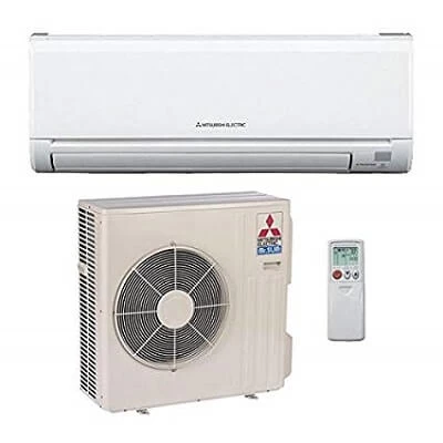
Mitsubishi Electrik PUHY-P300YHM-A/PLFY-100VBM в эксплуатации 5 лет.
Появилась ошибка на внешнем блоке — 2502/5/6
На внутренних блоках (4шт.) появляется авария 2502/6
через 3 минуты после вкл. с индивидуальных пультов PAR-21MAA.
По мануалу 2502/6 — неисправность помпы дренажа в 6 адресе.
Проливка кассетных ванн водным раствором EASY CLEANER
из пластиковой бутылки 1 литр запустила дренажные помпы (гудение слышно ухом), но авария 2502/6 сохранилась.
Обесточивание платы управления с адресом 6 аварию 2502/6 не устранила, по-прежнему 3 внутренних блока работали только 3 минуты на холод и останавливались с аварией 2502/6.
Работа на тепло тоже не удавалась, появлялась авария 2502/6.
Подозреваемая плата управления из адреса 6 была установлена в адрес 4.
Авария 2502/6 переместилась в другой внутренний блок с адресом 4.
Повторное вкл/выкл подозреваемой платы с ПДУ PAR-21MAA в адресе 4 устранило аварию 2502/6
Исправная плата управления из адреса 4 была установлена в адрес 6 — авария отсутствует. Теперь этот пульт и блок стали адресом 4.
1 — Что неисправно — поплавок, помпа или плата управления с адресом 6 — ?
2 — Почему на внешнем блоке мигало 2502/5/6 — ?
3 — Почему при одном забитом дренаже останавливается вся система кондиционеров — ?
4 — Как с ПДУ и внешнего блока определить кол-во блоков в системе — ?
Замечания.
Норма.
Поплавок сухой звонится тестером, как оборваный,
но обрыв разъема поплавка дает аварию 5701.
Значит поплавок емкостной, а не герконовый?
Определение адреса ПДУ.
В режиме ожидания дважды нажать CHECK
— в нижнем левом углу появится адрес этого ПДУ и внутр. блока.
Для определения принадлежности внутренних блоков к одному контуру был обесточен внешний блок, у него отдельный автомат.
Авария 51/6607 — обрыв связи с наружкой, на внутренних блоках появилась через 15 минут!
Если во внутреннем блоке, в плате с дипами и крутилками, установлена групповая конфигурация (BRANCH), то питание ПДУ отсутствует.
Today we are please to offer the complete list of Mitsubishi aircon error codes. No matter you want to troubleshoot your own Mitsubishi air conditioner or troubleshooting for clients, this mitsubishi ac troubleshooting guide will help.

Let’s get started with Mitsubishi electric air conditioner error codes first.
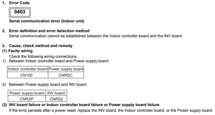
Mitsubishi error code 0403 (Serial communication error)
Cause : The fault occurs when there is a communication issue between PCB’s in the outdoor unit. If the model number is YGMA, YHMA, YJMA, YKMA or YLMA then the issue can be between the main board and inverter board or main board and fan board.
Check Procedure :
Check for poor connections and broken wiring between the boards. If the model number is YGMA, YHMA, YJMA, YKMA or YLMA, check the error detail code using the dip-switches section of the app to determine which PCB’s the transmission fault is with. If the detail code is 1, then the issue is between the main board and inverter board.
If the detail code is 5 then the issue is between the main board and fan board. Then check for poor connections between the PCB’s.
Technical Support Notes:
If there are no loose connections on either PCBs and the voltages are good then the Fan or Inverter PCB is usually at fault. This is not normally a problem with the main PCB.
Correct testing should allow you to identify which of the 2 boards is the cause. The online document link will take you to the document library where Service Handbooks can be viewed.
Mitsubishi error code 0900 (Test run)
Cause : Test operation dipswitch on the Lossnay circuit board has been set ON.
Check Procedure :
Check the position of Dipswitch SW2-1 on the main control board. If test is not required then set the dip switch to OFF.
Mitsubishi error code 1102 (Discharge temperature fault)
Cause : Insufficient cooling of the compressor caused by lack of refrigerant or a restriction in the refrigerant circuit, high ambient running conditions or airflow problems on either indoor or outdoor unit (depending on running mode), over heating of compressor through increased friction (compressor beginning to seize), faulty thermistor reading.
Check Procedure :
Use the testing dip switches in the app and check the system running pressures/temperatures and determine if the system is short of gas or if there is a restriction in the circuit – a restriction may show frosting where refrigerant expands, this could be a blocked strainer, faulty expansion valve operation or perhaps moisture in the system.
Check compressor running current -if higher than expected this could show a compressor issue.
Mitsubishi error code 1301 (Low pressure fault)
Cause : Possible refrigerant leak. Restriction or blockage in refrigerant circuit causing low side pressure to drop. Problem with pressure sensor reading incorrectly.
Check Procedure :
Check the system standing pressure for a complete gas loss.
Use the Testing dip switches in the app and compare system gauge pressure to Low Pressure Sensor reading – If the pressure sensor is faulty it will read 0.0 bar even though there is pressure in the system.
Technical Support Notes :
Using the testing dip switches check the system running pressures/temperatures to determine if the system is short of gas or if there is a restriction/blockage in the circuit.
For refrigerant circuit diagram click the link below and type unit model number into the document library search box
Mitsubishi error code 1302 (High pressure fault)
Cause : High pressure faults are commonly caused by a blocked condenser coil, faulty fan motor, a restriction of airflow on indoor units in heating mode or a blockage/restriction in the pipework.
Check Procedure :
Check outdoor fan operates correctly, ensure no restriction of airflow across indoor/outdoor coils such as clogged filters. Use the testing dip switches in the app to check system running pressures/temperatures – This may help highlight any blockages or restrictions in the refrigerant circuit such as faulty solenoid valves or check valves stuck closed.
Technical Support Notes :
If the you reset the unit and the fault generates straight away (without running) then the high pressure switch or sensor may be at fault. Measure the switch for continuity (normally closed) and use the dip switches to check the pressure sensor reading against your gauge pressure.
Mitsubishi error code 1500 (Refrigerant overcharge)
Cause : Normally caused by excessive refrigerant returning to the outdoor unit which over-cools the compressor. System is either over-charged or there are valves operating incorrectly allowing refrigerant to ‘flood’ back to the compressor.
Check Procedure :
Check correct reading of high pressure sensor and discharge thermistor. Check for excessive refrigerant returning to the outdoor unit through overcharge of gas, incorrect valve operation in the system or issue with linear expansion valve (LEV) control in BC Box or Indoor unit
Technical Support Notes :
An indoor LEV stuck open can be an obvious cause to this issue. Try running the system in full cooling and then checking if there is an indoor unit that performs much better than the others.
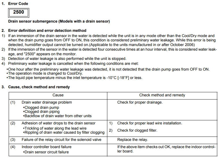
Mitsubishi error code 2500 (Drain sensor submergence)
Cause : Water pump off/faulty. Water flow rate too slow. Float switch faulty.
Check Procedure :
Check water pump. Check water flow rate. Check continuity of float switch.
Mitsubishi error code 2502 (Drain pump fault)
Cause : The indoor unit drain float has detected a high water level in the drip tray.
Check Procedure :
Check the indoor drip tray for water. If there is excessive water then there may be an issue with the internal pump or drains. If the tray is dry or hasn’t enough water to lift the float switch then check the float switch for continuity. If the switch is lifted the circuit should be made. If the switch is down then the circuit should be open.
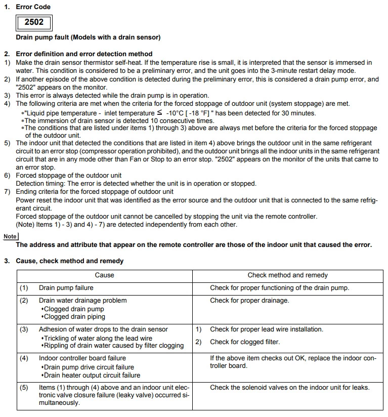
Technical Support Notes :
The internal lift pump is not activated by the float switch, the pump is activated when cooling mode is selected. This fault is triggered by the float switch circuit closing.
Mitsubishi error code 2503 (Drain sensor fault)
Cause : The drain sensor is open/short circuit.
Check Procedure :
If the drip tray is clear then check the resistance of the drain sensor as an open circuit or short circuit can cause the fault.
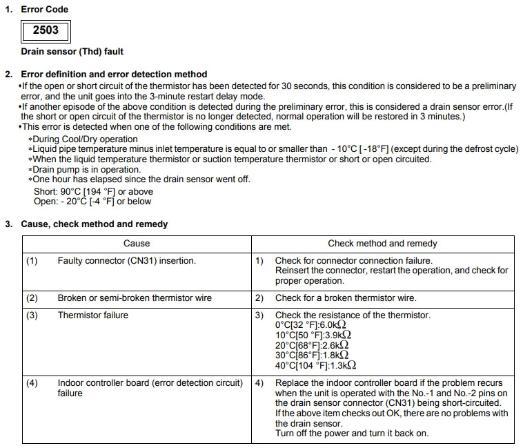
Technical Support Notes :
Check the wiring diagram to see if the indoor unit has a float switch or sensor. If the wiring diagram shows a float switch and not a sensor check the dip switch settings for the unit model you are working on.
Mitsubishi error code 2600 (Water leakage)
Cause : Water leak from pipes on humidifier.
Check Procedure :
Check that water does not leak from pipes in humidifier.
Mitsubishi error code 4102 (Open phase)
Cause : Missing main phase.
Check Procedure :
Check power supply and noise filter for correct 3 phase, check wiring and fuses.
Mitsubishi error code 4106 (Transmission power supply fault)
Cause : Transmission (M-Net), incorrect wiring.
Check Procedure : Check wiring, high current, incorrect voltage on transmission line and/or M-Net board. Make sure M-net transmission wiring is daisy chained.
Mitsubishi error code 4115 (Power supply signal sync error)
Cause : Incorrect power supply, blown fuses or possible faulty PCB.
Check Procedure :
Check mains power is correct, check the fuses, and connections PCB.
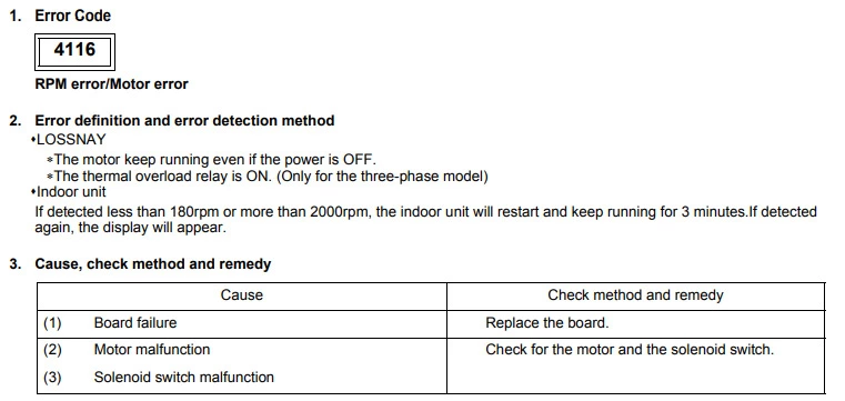
Mitsubishi error code 4116 (RPM error/Motor error)
| Cause | Check Procedure |
|---|---|
| Faulty connection of a fan. | Check the connection for the fan motors. |
| Faulty connection of the leads between the Control board and the Power board. | Check the connections between the Control board and the Power board. |
| Model selection switch SW6 is set incorrectly. | Confirm that the model selection switch SW6 is set correctly for the model. |
| Ambient temperature in which the unit is located is high. | Check the temperature around the Lossnay. |
| Fan isn’t fixed correctly. | Confirm that the fan motors are fixed securely. |
| Deformed centrifugal fan. | Check that the centrifugal fan is clear of debris. |
| Centrifugal fan has foreign objects in or around it. | Replace the fan motor. |
| Fan motor fault. | Replace the circuit board. |
| Circuit board fault. | Check the connections of the reactor (TB3-4) and check the resistance of it. |
| Faulty connection of the reactor. | To identify which fan the issue is with, check the LED flashing sequence and contact After Sales Technical Support. |
Mitsubishi error code 4220 (Abnormal bus voltage)
Cause : Low mains power supply, diode fault.
Check Procedure :
Check mains supply. Check DC bus voltage coming from diode.
Mitsubishi error code 4225 (Low bus voltage)
Cause : Incorrect mains supply or fan board fault.
Check Procedure :
Check mains power is ok and there is at least 300vdc at the diode stack.
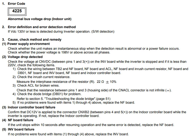
Technical Support Notes :
Check to see if the error led is lit on the fan board, this is a good indication that the fan board is the issue.
Mitsubishi error code 4230 (Heatsink overheat protection)
Cause : Blockage in air passage of inverter heatsink, Inverter board failure, inverter fan failure.
Check Procedure :
Check blockages in air duct failure of INV fan or failure of thermistor.
Mitsubishi error code 4240 (Overload protection)
Cause : If high current is detected for more than 10mins.
Check Procedure :
Check inverter balance. Reduced airflow through heat sink.
Mitsubishi error code 4250 (Over current protection)
Cause : High amps drawn by the compressor or an issue with the inverter.
Check Procedure :
Carry out an inverter output test to check if the inverter is working correctly. Use the “inverter testing guide” in the City Multi section of the APP. If the inverter is ok then check the compressor windings for a short or open circuit.
Technical Support Notes :
Use the service dipswitches on the outdoor unit to get the detail code which will indicate if the issue is with the inverter or compressor.
Mitsubishi error code 4255 (Outdoor fan error)
Cause : Grounding fault of fan motor or fan board fault.
Check Procedure :
Check the voltage on CNVDC on the fan. This should be a high DC voltage around 580vdc.
Also check the fan motor windings for an open or short circuit.
Technical Support Notes :
Use the service dipswitches on the outdoor unit to get the detail code which will indicate if the issue is with the fan board or fan motor.
Mitsubishi error code 4260 (Heatsink overheat protection at startup)
Cause : Reduced airflow through heat sink.
Check Procedure :
Fan motor problem. THHS thermistor problem.
Mitsubishi error code 5101 (Temperature sensor fault)
| Cause | Check Procedure |
|---|---|
| Faulty thermistor – dead short/open circuit. | The fault can be related to indoor or outdoor so check the fault code for address of unit in fault first. |
| Damaged thermistor cable or poor connection to PCB. | Check connection of thermistor on PCB and thermistor wiring. |
| PCB incorrectly reading thermistor value. | Unplug thermistor and test resistance value. |
If all the above are correct then replace the PCB.
Technical Support Notes :
Correct reading of thermistor can be determined using Thermistor Value Look Up in the app.
Check whether the thermistor is for reading High temperature e.g .Discharge, or Normal running e.g. Ambient/Liquid, to determine which range to check against.
Mitsubishi error code 5102 (Return Air thermistor fault)
Cause : The circuit board cannot read the thermistor correctly
Check Procedure :
Check the connection onto the circuit board.
Check the resistance of the thermistor.
Replace the thermistor.
Replace the circuit board.
Mitsubishi error code 5110 (Outdoor inverter heatsink thermistor error)
Cause : Reduced airflow through inverter heatsink.
Check Procedure :
Open/short circuit sensor, disconnected from PCB.
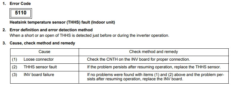
Technical Support Notes :
On the YGM-A series this can be either THHS1 or THHS5. To find out which it is you will need to check the inverter detail code using SW1 on the control board. Turn on SW1 dips 1,2,5,6,8 and look at the display for the code to be retrieved. THHS1=01 and THHS5=05.
Mitsubishi error code 5201 (Pressure sensor fault)
Cause : PS1 Pressure fault.
Check Procedure :
Check pressure reading using the dipswitches on the outdoor. Check connection of PS3 on PCB.
Mitsubishi error code 5301 (Current sensor fault)
Cause : ACCT or DCCT sensor error.
Check Procedure :
Check inverter error details, check resistance of current sensor, check connections of sensors.
Mitsubishi error code 5701 (Loose float switch connector)
Cause : The indoor unit internal float switch connector has detected an open circuit.
Check Procedure :
Check the float switch is operating correctly. If the switch is down then the switch should be open.
Also check for external pumps wired in across the fail safe connection.
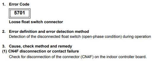
Technical Support Notes :
This fault normally occurs when an external pump is wired in across the fail safe connections, (CN4F/CN31) and the external pump has failed. Or the connection is loose.
Mitsubishi error code 6201 (Remote controller issue)
Cause : The remote controller is faulty
Check Procedure :
Replace the controller.
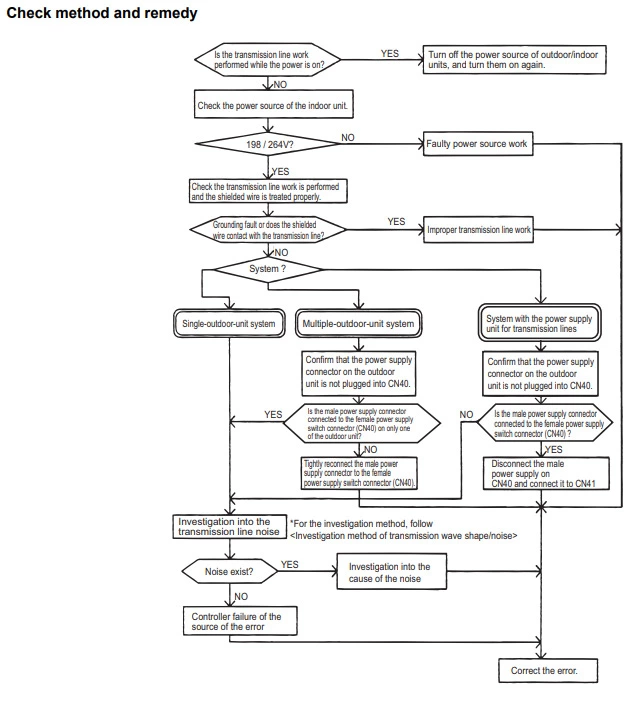
Mitsubishi error code 6600 (Address overlap)
Cause : There is more than one unit with the same MNET address or two or more devices are addressed the same.
Check Procedure :
Check the address set on each device on the same MNET network.
Check address settings on outdoors, indoors, BC boxes and remote controllers to see if two have the same address settings.
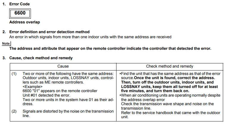
Technical Support Notes :
This is only caused when two items are addressed the same. If they all look like they are set correctly power the system down and spin the address dials all the way around to confirm they are clicked into the position they should be. If the system also has a 6607 fault this could indicate where the repeat address has occurred.
Mitsubishi error code 6601 (Polarity setting error)
Cause : No voltage or short circuit on M-Net transmission line TB7.
Check Procedure :
Check TB7 connections on outdoors and central controllers. Check for voltage on TB7. Check cable size and spec.
Mitsubishi error code 6602 (Transmission processor hardware error)
| Cause | Check Procedure |
|---|---|
| Noise interference. Polarity problem on TB7. | Check M-Net connection on TB7 and central controller. Check cable size/spec. |
| Controller where the error originally occurred is defective. | Check the controller where the error occurred and replace if required. |
| Lossnay circuit board is defective. | Replace the circuit board. |
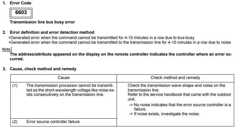
Mitsubishi error code 6603 (Transmission line bus busy error)
Cause :
Power is supplied to the same transmission cable from two or more power supply units.
The power supply unit is connected to TB3 side of the power supply expansion units.
The power supply units connected to the indoor and outdoor transmission cables.
Check Procedure :
Adjust the wiring of the power supply unit.
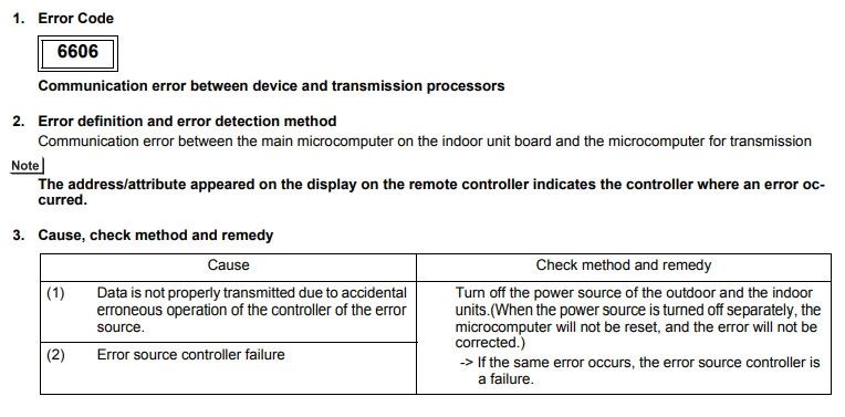
Mitsubishi error code 6606 (Communication fault)
Cause :
Poor connection of MNET terminals.
MNET cables have been terminated whilst the unit is powered.
Malfunction of the unit PCB.
Check Procedure :
Check that the MNET cables have been terminated correctly.
Reset power to the system.
Inspect the Control Board for damage.
Replace the Control Board.
Mitsubishi error code 6607 (No ACK error)
Cause :
Lossnay has no power.
Lossnay address has been changed.
Transmission cable is in excess of 500m.
Transmission cable is not securely terminated.
Check Procedure :
Check the power supply to the Lossnay.
Check the Lossnay address.
Check the cable length.
Check the cable termination.
Technical Support Notes :
The 6607 fault should also give you the address of the item in fault, if it does check power and M-Net voltage at the item.
If no address is given with the fault code then this is referred to as a “ghost fault”, this is caused when something with an address is physically removed from the system without being deleted first.
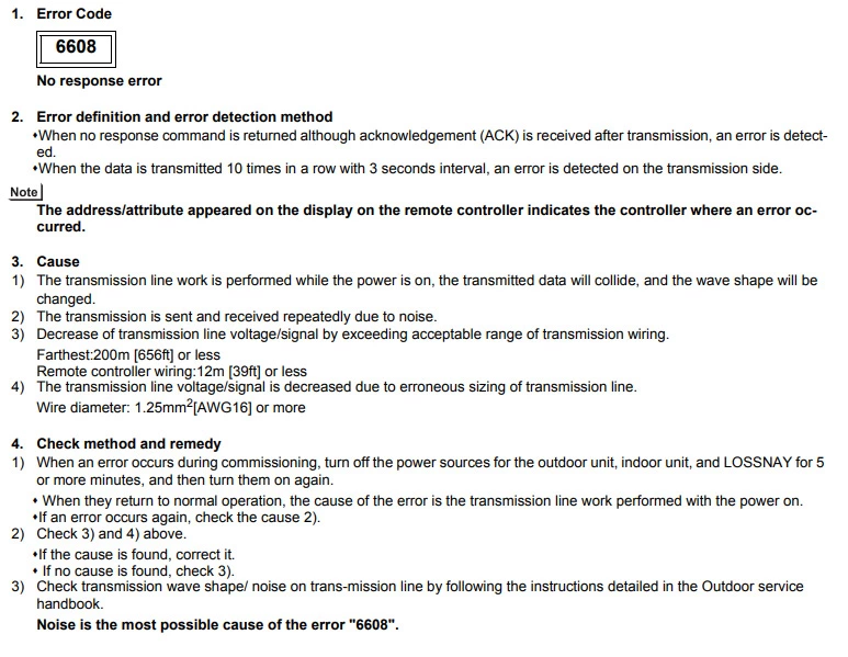
Mitsubishi error code 6608 (No response error)
Cause :
When using multiple Lossnay units, the Main/Sub switch has not been set.
Interference on the transmission line.
Cable length is in excess of 500m.
Transmission cable is not securely connected.
Multi core cable is being used for multiple uses and causing interference.
Check Procedure :
Isolate power and set the lead unit to Main using SW1 and the remaining units to Sub.
Check and repair cable terminations.
Check the length of the transmission cable.
Check that the cable used is as specified.
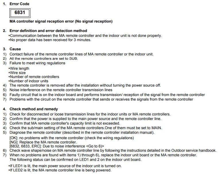
Mitsubishi error code 6831 (MA controller signal reception error)
Cause : MA controller being wired into the M-Net. Wrong cable size/spec.
Check Procedure :
Check where remote is wired to, check cable length no bigger than 500 meters, check connection and type of cable used, check R/C not set Sub on field settings.
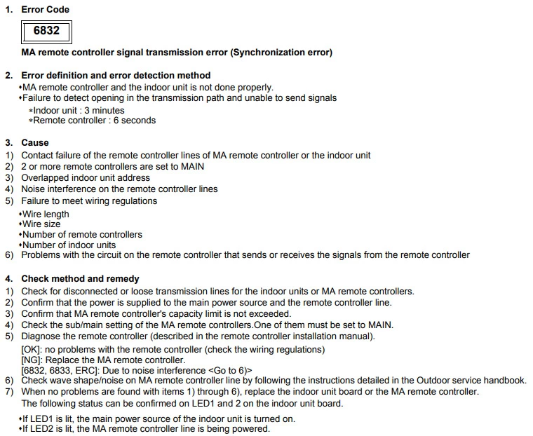
Mitsubishi error code 6832 (MA controller comms fault)
Cause : MA controller being wired into the M-Net. Wrong cable size/spec.
Check Procedure : Check where remote is wired to, check cable length no bigger than 500 meters, check connection and type of cable used, check R/C not set Sub on field settings.
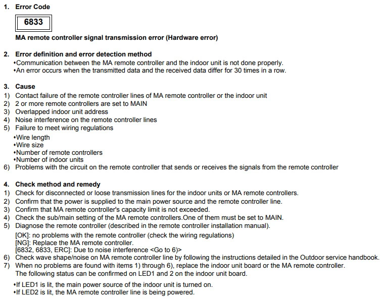
Mitsubishi error code 6833 (MA controller comms fault)
Cause : MA controller being wired into the M-Net. Wrong cable size/spec.
Check Procedure :
Check where remote is wired to, check cable length no bigger than 500 meters, check connection and type of cable used, check R/C not set Sub on field settings.
Mitsubishi error code 6834 (MA controller signal reception error)
Cause : MA controller being wired into the M-Net instead of the remote terminals. Wrong cable size/spec.
Check Procedure :
Check where remote is wired to, check the cable length is no bigger than 500 meters, check connection and type of cable being used, check R/C not set Sub on field settings.
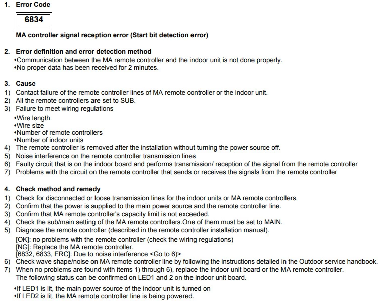
Technical Support Notes :
This is usually caused when an M-Net controller is replaced with an MA controller. Make sure if you have an M-Net remote it is wired into the M-Net terminals and if you have an MA remote it is wired into the remote controller terminals.
Mitsubishi error code 7100 (Total capacity error)
Cause :
The total indoor unit capacity exceeds the outdoor unit allowable capacity.
On a PURY outdoor you are allowed up to 150% of its capacity.
On a PUHY/PUMY outdoor you can have up to 130% of its capacity.
Check Procedure :
Add up all the capacities of the indoor units and check they don’t exceed the outdoor unit capacity.
Also check the capacity dip switches on the indoor and outdoor unit are set correctly.
Technical Support Notes :
This fault can be caused when the system is comprised of two outdoor units piped together and power is lost to one of the outdoors.
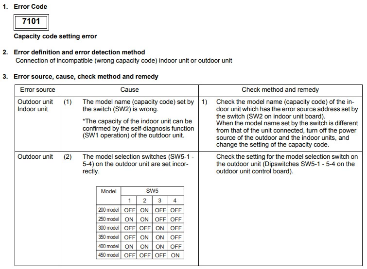
Mitsubishi error code 7101 (Capacity code setting error)
Cause : SW2 set wrong on indoors, SW5 dips set wrong on YHM-A outdoor, SW3-10 on older kit.
Check Procedure :
Capacity dips on indoor and outdoor units.
Mitsubishi error code 7102 (Wrong number of connected units)
Cause : The outdoor unit is not seeing any indoor units or it is seeing more than the allowable value.
Check Procedure :
Check voltage on M-Net, power to the BC box, check dip switches are set correctly on the BC box and the model type of BC box is correct for the system.
Technical Support Notes :
Check the voltage on the M-Net at the outdoor unit (it should be 29vdc). If there is no voltage then power down and remove the M-Net and check the terminals again. If you then get 29vdc then there is an issue somewhere on the M-Net, a loose connection or short maybe.
Mitsubishi error code 7105 (Address setting error)
Cause : OC or BC addressed wrong.
Check Procedure :
Check address setting on OC and BC.
Mitsubishi error code 7106 (Attribute setting error)
Cause : GUF unit being used on City Multi system.
Check Procedure :
Make sure SW3-1 setting is on, on the GUF.
Mitsubishi error code 7110 (Signal transmission error)
Cause : Loose or misswiring of TB3 or TB7. SW5 dip 7 not set on outdoor. Transmission booster turned off.
Check Procedure :
Check M-Net connections, dipswitches on outdoors.
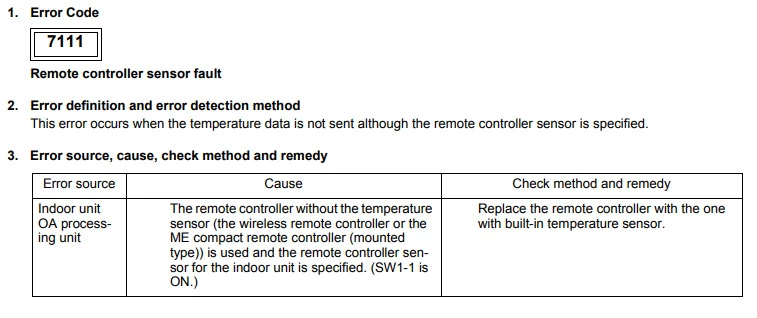
Mitsubishi error code 7111 (Remote controller sensor fault)
Cause : SW1 – 1 on and no controllers fitted or faulty remote controller.
Check Procedure :
Check SW1 – 1 on the indoor unit if no remote controllers fitted.
Mitsubishi error code 7113 (Function setting error)
Cause :
More than 1 unit in the group is set to as the Main Lossnay (SW5-10 ON)
The group contains two or more units with the same address.
The Lossnay that is set to the Main, has not been set to the lowest unit address in the group.
The MA remote controller for the air conditioner (Mr.Slim or City Multi) is connected to the Lossnay.
Incorrect wiring of the remote controller terminals.
The Lossnay LGH-RVX is in the same group as a Lossnay LGH-RX5.
The model selection switch SW6 is not set correctly.
Check Procedure :
Check the SW5-10 setting on the Lossnays in the same group and confirm that there is only one set to Main(ON)
Check the address settings of the Lossnay units.
Change the remote for a PZ-61DR-E.
Check that the wiring of the remote terminals and the MNET terminals.
The LGH-RVX and the LGH-RX5 cannot be used in the same group.
Confirm that the SW6 setting is correct for the model.
Mitsubishi error code 7117 (Model setting error)
Cause : SW5 set wrong on the outdoor or wrong resistors fitted.
Check Procedure :
Check dips, resistors and thermistors.
Mitsubishi error code 7130 (Incompatible unit combination)
Cause : Check split with MAC 399 wired onto the TB5 line not the TB7.
Check Procedure :
Check M-Net wiring on systems.
Now, let’s proceed with Mitsubishi heavy air conditioner error codes. If you want to learn more about Mitsubishi heavy vs electric, please refer to our previous guide for more info.
Mitsubishi error code E1 (Remote controller communication issue)
Cause : Faulty controller or poor wiring connection/abnormal voltage to the Remote controller
Check Procedure :
Check the remote controller wiring connection onto the FTC terminals and ensure there is 12vdc down to the Remote controller.
Make sure LED2 is lit on the FTC Control board
Mitsubishi error code E2 (Remote controller transmitting error)
Cause : Incorrect wiring of remote or incorrect dip switch setting if units are grouped.
Check Procedure :
Check unit addressing if grouped or check remote is only wired to master indoor unit.
Mitsubishi error code E3 (Remote controller communication/receiving error)
Cause :
Incorrect settings on SW1 switches at the outdoor unit.
Poor connection or wiring of the remote controller.
Check Procedure :
Check for 12vdc down to the controller and make sure LED 2 is lit on the FTC board
Check the SW1 dips switches on the outdoor unit are set correctly.
Mitsubishi error code E5 (Remote controller communication/receiving error)
Cause :
Remote controller incorrectly wired or the controller does not have the correct 12vdc supply.
Incorrect settings on SW1 switches at the outdoor unit.
Check Procedure :
Check for 12vdc down to the controller and make sure LED 2 is lit on the FTC board.
Check the SW1 dips switches on the outdoor unit are set correctly.
Mitsubishi error code E6 (Indoor to outdoor communication fault)
Cause : Loss or no communication between the FTC and outdoor Ecodan. Poor connection of the interconnecting cable or not the correct 12-24vdc fluctuating voltage between S2 and S3.
Check Procedure :
Reset power supply to both indoor FTC and outdoor Ecodan. Power back up the indoor first then the outdoor. Check interconnecting cable connections and voltages. Check indoor FTC LEDs.
Technical Support Notes :
The most common cause of an E6 fault is external noise interference caused by condensate pumps being wired into S1 & S2. If a pump is wired in to S1 & S2 and you have an E6, then try disconnecting the pump and repowering the system to see if it works.
Mitsubishi error code E7 (Comms failure indoor to outdoor)
Cause : Mis-wiring of indoor to outdoor cable. System powered up incorrectly.
Check Procedure :
Check for pumps wired in, Check indoor isolator, Repower in correct sequence i.e. indoor then outdoor.
Mitsubishi error code E8 (Indoor to Outdoor communication error)
Cause : Loss or no communication between the FTC and outdoor Ecodan. Poor connection of the interconnecting cable or not the correct 12-24vdc fluctuating voltage between S2 and S3.
Check Procedure :
Reset power supply to both indoor FTC and outdoor Ecodan. Power back up the indoor first then the outdoor. Check interconnecting cable connections and voltages. Check indoor FTC LEDs.
Mitsubishi error code E9 (Indoor to outdoor communication error)
Cause :
Loss or no communication between the FTC and outdoor Ecodan. Poor connection of the interconnecting cable or not the correct 12-24vdc fluctuating voltage between S2 and S3.
SW8-3 set to OFF when independent power supplies are used.
Check Procedure :
Reset power supply to both indoor FTC and outdoor Ecodan. Power back up the indoor first then the outdoor. Check interconnecting cable connections and voltages. Check indoor FTC LEDs.
Power down complete system and set SW8-3 to ON before powering the FTC before the Ecodan.
[7-4 Error Code Definitions and Solutions: Codes [2000 — 2999] ]
7-4-4
1. Error code definition
Drain pump fault
2. Error definition and error detection method
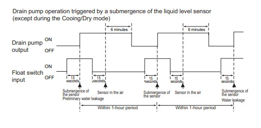
1) The immersion of sensor tip in water is detected by the ON/OFF signal from the float switch.
∗Submergence of the sensor
When it is detected that the float switch has been ON for 15 seconds, it is interpreted that the sensor tip is immersed in
water.
∗Sensor in the air
When it is detected that the float switch has been OFF for 15 seconds, it is interpreted that the sensor tip is not immersed
in water.
2) If it is detected that the float switch has been ON for 3 minutes after the immersion of the sensor tip was detected, this is con-
sidered a drain pump failure, and «2502» appears on the monitor.
∗The total time it takes for this error to be detected is 3 minutes and 15 seconds, including the time it takes for the first im-
mersion of the sensor tip to be detected.
3) Detection of drain pump failure is performed while the unit is stopped.
4) The following criteria are met when the criteria for the forced stoppage of outdoor unit (system stoppage) are met.
∗»Liquid pipe temperature — inlet temperature
∗It is detected by the float switch that the sensor tip has been immersed in water for 15 minutes or more.
∗The conditions that are listed under items 1) through 3) above are always met before the criteria for the forced stoppage
of the outdoor unit.
5) The indoor unit that detected the conditions that are listed in item 4) above brings the outdoor unit in the same refrigerant
circuit to an error stop (compressor operation prohibited), and the outdoor unit brings all the indoor units in the same refrigerant
circuit that are in any mode other than Fan or Stop to an error stop.
6) Forced stoppage of the outdoor unit
Detection timing: The error is detected whether the unit is in operation or stopped.
This error is detected whether the unit is in operation or stopped.
7) Ending criteria for the forced stoppage of outdoor unit
Power reset the indoor unit that was identified as the error source and the outdoor unit that is connected to the same refrig-
erant circuit.
Forced stoppage of the outdoor unit cannot be cancelled by stopping the unit via the remote controller.
(Note) Items 1) — 3) and 4) — 7) are detected independently from each other.
The address and attribute that appear on the remote controller are those of the indoor unit (or OA processing unit)
that caused the error.
3. Cause, check method and remedy
(1)
Drain pump failure
(2)
Drain water drainage problem
Clogged drain pump
Clogged drain piping
(3)
Stuck float switch
Check for slime in the moving parts of the float switch.
(4)
Float switch failure
(5)
Indoor unit control board failure
Drain pump drive circuit failure
Float switch input circuit failure
(6)
Items (1) through (5) above and an indoor unit electronic
valve closure failure (leaky valve) occurred simultane-
ously.
HWE13080
— 10°C [ -18°F] » has been detected for 30 minutes.
Cause
— 187 —
Check method and remedy
Check for proper functioning of the drain pump
mechanism
Check for proper drainage.
Check for normal operation of the float switch.
Check the resistance with the float switch turned
on and turned off.
Replace indoor unit control board.
Check the solenoid valves on the indoor unit for
leaks.
GB
Mitsubishi Error Code 2502 is an indication of a communication failure between the air conditioning system’s indoor and outdoor units. This could be caused by either a faulty connection or a fault in one of the components. The code should be cleared once the issue has been resolved, but before attempting to do so it is important to identify the source of the problem.
Generally this requires professional assistance from an experienced HVAC technician who can inspect all relevant parts and wiring, and ascertain which component needs attention or replacing.
If you own a Mitsubishi vehicle, then you may have encountered the error code 2502. This fault code is typically caused by an issue with the vehicle’s powertrain control module (PCM), and it can lead to reduced performance in your engine or even complete stalling. To diagnose this issue, you should take your car to a qualified technician as soon as possible so they can get to the root of the problem and make sure that your Mitsubishi vehicle is running safely and efficiently again.
Mitsubishi Error Code 2503 is a common error code that indicates an issue with the vehicle’s computer system. It could indicate a problem with the ECU or other electrical components, and it usually requires professional diagnostics to pinpoint the exact cause of this error. In some cases, replacing certain parts can help resolve this issue.
Mitsubishi Error Code 5106
Mitsubishi Error Code 5106 is a diagnostic trouble code (DTC) that indicates the Vehicle Speed Sensor has detected an issue. The DTC also indicates a problem in the vehicle’s transmission system or other related components. If this error code appears, it’s important to have your vehicle inspected and serviced immediately by a qualified mechanic to prevent further damage.
Mitsubishi Error Code 4255
Mitsubishi Error Code 4255 is an internal communications error code that indicates a communication issue between the engine control unit (ECU) and the transmission control module (TCM). It typically occurs when either one of these two components has become out-of-sync, resulting in a drop in performance or malfunction. To fix this error, it’s important to have both modules reset by a professional technician who can diagnose and repair any underlying issues with your Mitsubishi vehicle.
Mitsubishi Error Code E06
Mitsubishi Error Code E06 is a diagnostic trouble code indicating an issue with the Evaporative Emission Control System (EVAP) in your Mitsubishi vehicle. This can be caused by a leak, clogged filter, or faulty sensor. Symptoms might include fuel odors from the engine bay, poor fuel economy, and stalling of the engine when refueling.
It’s important to have this error code addressed as soon as possible to ensure proper operation of your car’s EVAP system.
Mitsubishi Error Code 2505
Mitsubishi Error Code 2505 is an indication of a faulty or shorted MAP Sensor, which can cause your vehicle’s engine to misfire. This code indicates that the ECU (Engine Control Unit) has detected a problem with the MAP Sensor and, as such, requires immediate attention and repair to prevent further damage to your engine.
Mitsubishi Error Code 5102
Mitsubishi Error Code 5102 is an indication that there has been a failure in the evaporator temperature sensor. This error code can be caused by a faulty or dirty sensor, as well as low refrigerant levels or blocked airflow within the system. To fix this issue, Mitsubishi recommends replacing the evaporator temperature sensor and performing system diagnostics to check for any other problems that may have contributed to the error code.
Additionally, it’s important to clean out any dirt and debris from around the sensors and inspect your air filter for blockages in order to ensure optimal performance of your unit.

Credit: www.manualslib.com
What is Error 2502 on Mitsubishi Thermostat?
Error 2502 on a Mitsubishi thermostat is an indication that the system has detected a fault in the wiring. This error can be caused by incorrect wiring, improper connection of wires, shorts or other electrical problems. To fix this issue, you should inspect all of your wiring to make sure it is properly connected and free from any shorts or damage.
If everything checks out okay then you may need to reset the thermostat itself in order to clear this code and get your system up and running again.
How Do I Fix Error Code 5102?
Error code 5102 is a common error that occurs with Canon printers. To fix this issue, start by checking the printer’s connection to your computer or network. Make sure that all cables are securely connected and not damaged in any way.
If necessary, try connecting to another port or device on the same network. Additionally, if you’re using a wireless connection, check your router settings and make sure it’s configured correctly for printing over the internet. Finally, you may need to update the drivers for your printer; consult your printer manual for instructions on how to do this correctly.
What is Uh Error Code in Mitsubishi Electric?
UH error code in Mitsubishi Electric indicates that the air conditioner has detected an abnormality with its heat exchanger. This could be caused by a number of issues, such as a blocked or damaged heat exchanger, insufficient air flow due to dirty filters or improper installation. To fix this issue it is important to contact a professional HVAC technician who can diagnose the cause and provide an appropriate solution.
What is Error Code 5103 on Mitsubishi Ac?
Error code 5103 on Mitsubishi ACs is a communication error that occurs when the indoor and outdoor units of your air conditioner are not communicating properly. This can be caused by an issue with either the wiring or the control board. To resolve this, check all connections between both units to ensure they are securely attached and free of any damage.
Additionally, you might need to replace the control board if it is faulty. It’s important that you contact a qualified specialist for further diagnosis and repair since improper handling could result in further damage to your unit.
HOW TO FIX 2502 ERROR CODE IN CEILING CASSETTE TYPE VLOG 007
Conclusion
In conclusion, Mitsubishi Error Code 2502 is an issue that can be easily resolved with the help of a technician. The error code is usually caused by a faulty component in the engine control unit or other issues related to the ECU. It is important to have your vehicle checked by a qualified professional if you are experiencing this error code so that it does not become worse and cause more damage down the road.
{
“@context”: “https://schema.org”,
“@type”: “FAQPage”,
“mainEntity”:[{“@type”: “Question”,
“name”: “What is Error 2502 on Mitsubishi Thermostat? “,
“acceptedAnswer”: {
“@type”: “Answer”,
“text”: ”
Error 2502 on a Mitsubishi thermostat is an indication that the system has detected a fault in the wiring. This error can be caused by incorrect wiring, improper connection of wires, shorts or other electrical problems. To fix this issue, you should inspect all of your wiring to make sure it is properly connected and free from any shorts or damage. If everything checks out okay then you may need to reset the thermostat itself in order to clear this code and get your system up and running again.”
}
}
,{“@type”: “Question”,
“name”: “How Do I Fix Error Code 5102? “,
“acceptedAnswer”: {
“@type”: “Answer”,
“text”: ”
Error code 5102 is a common error that occurs with Canon printers. To fix this issue, start by checking the printer’s connection to your computer or network. Make sure that all cables are securely connected and not damaged in any way. If necessary, try connecting to another port or device on the same network. Additionally, if you’re using a wireless connection, check your router settings and make sure it’s configured correctly for printing over the internet. Finally, you may need to update the drivers for your printer; consult your printer manual for instructions on how to do this correctly.”
}
}
,{“@type”: “Question”,
“name”: “What is Uh Error Code in Mitsubishi Electric? “,
“acceptedAnswer”: {
“@type”: “Answer”,
“text”: ”
UH error code in Mitsubishi Electric indicates that the air conditioner has detected an abnormality with its heat exchanger. This could be caused by a number of issues, such as a blocked or damaged heat exchanger, insufficient air flow due to dirty filters or improper installation. To fix this issue it is important to contact a professional HVAC technician who can diagnose the cause and provide an appropriate solution.”
}
}
,{“@type”: “Question”,
“name”: “What is Error Code 5103 on Mitsubishi Ac? “,
“acceptedAnswer”: {
“@type”: “Answer”,
“text”: ”
Error code 5103 on Mitsubishi ACs is a communication error that occurs when the indoor and outdoor units of your air conditioner are not communicating properly. This can be caused by an issue with either the wiring or the control board. To resolve this, check all connections between both units to ensure they are securely attached and free of any damage. Additionally, you might need to replace the control board if it is faulty. It’s important that you contact a qualified specialist for further diagnosis and repair since improper handling could result in further damage to your unit.”
}
}
]
}
My name is Aris, and I am a certified HVAC technician. I have been working in this field for over 5 years and have a lot of experience with different AC units. I write here to help people solve their Air Conditioning problems and find the best solutions for their needs.
If you are having any issues with your air conditioner or are thinking about buying a new one, be sure to check out my blog!
X
закрыть

Здравствуйте!
Оставьте номер, и мы Вам перезвоним!
Подтвердите что вы не робот
Найдена следующая информация по ошибке P2502 для автомобиля MITSUBISHI PAJERO (2000-2006), V6/V7:
На русском языке:
Напряжение системы зарядки
На английском языке:
Charging System Voltage
Вы можете задать вопрос или поделиться опытом устранения ошибки P2502 на автомобиле MITSUBISHI с другими пользователями.
Возможную причину возникновения и советы по устранению можно найти в каталоге причин и советов:
Найти причину >>>
Ошибки (коды ошибок) полученные от прибора, сканера требуют правильной интерпретации информации, дабы не тратить время и деньги на замену работающих элементов автомобиля.
Проблема зачастую кроется намного глубже чем кажется на первый взгляд. Это& вызвано теми обстоятельствами, что информационные сообщения содержат, как было выше сказано, косвенную информацию о нарушении работы системы.
Может быть полезным для решения вопроса по устранению неисправности у Mitsubishi Pajero (V6/V7):
Проводка, генератор, аккумуляторная батарея
Проводка, генератор, аккумуляторная батарея
Mitsubishi Electric Corporation was established in 1921 and worked its way to becoming a leading multinational electrical equipment and electronics manufacturer. With its headquarters in Tokyo, there was a time the company only focused on elevators, escalators, and high-end appliances such as air conditioners. While the company has grown, these three remain to be their top candidates.
When it comes to air conditioning the company offers ac systems such as room air conditioners, package air conditions, VRF systems, Ventilators, air curtains, and so on. Along with endless home and commercial appliances that start with toasters and ends with elevators and moving walks. With its main focus on air conditioners, Mitsubishi is one of the leading designers, manufacturers, and providers in the world. Yet, there are times when customers find themselves baffled by a random code on their appliance.
To help you out we have listed down some of the most common error codes for Mitsubishi Air conditioners. Start by noting down the error code, and match it using the list below. Once you have the error code you can understand the main issue with your Mitsubishi air conditioner, and draw out a solution that works to your advantage.
Mr Slim P Series (A)
Mr. Slim P-Series ductless heat pumps and air conditioners are compact yet powerful, offering unrivaled energy efficiency and design flexibility. Their advanced technology has been designed and tested to withstand the extremes of the Canadian climate in order to deliver a reliable and proven climate control system that you can trust all year round. With a variety of models to choose from, there’s a P-Series solution for any commercial application.
| Fault Codes | Problem |
|---|---|
| A0 | Duplicate address — Lossnay units attached with the same address — change addresses and reset the units power |
| A2 | Hardware error of transmission processor (Lossnay) — check comms wiring, and for possible Lossnay board fault |
| A3 | Line busy no data could be transmitted for 8 minutes — check A- M-Net connections (TB7 and TB3) |
| A6 | Communication error with communication processor — Lossnay address not transmitted — check M-Net voltage |
| A7 | No ACK signal — check A- M-Net wiring, range of transmission wiring exceeded or if faulty A- M-Net converter |
| A8 | M-Net no response — check A- M-Net wiring, range of transmission wiring exceeded, faulty A- M-Net converter or if incorrect wire used for M-Net connection |
| EA | Mis-wiring/loose inter-connecting cables. Noise interference |
| EB | Mis-wiring/loose interconnecting cables. Noise interference. Wrong cable size/spec |
| EC | Start-up time over. The unit has failed to initialise after power up. Noise interference. Wrong cable size/spec |
| ED | Serial communication error. Comms error between boards on outdoor unit caused by M-Net interface board incorrectly fitted |
| EF | Non-defined error code. Noise interference — power down outdoor unit for 30 seconds then switch back on |
| E0 | Remote controller communication error — check wiring, connections and comms voltage. Also check Master/Slave settings if multiple systems are connected |
| E1 | Remote controller issue — if grouped, check addressing. If twinned, check wired to master indoor only |
| E2 | Remote controller issue — if grouped, check addressing. If twinned, check wired to master indoor only |
| E3 | Remote controller issue — not transmitting — if grouped, check addressing. If twinned check wired to master indoor only |
| E4 | Remote controller issue — not receiving — if grouped, check addressing. If twinned, check wired to master indoor only |
| E5 | Remote controller issue — not receiving — if grouped, check addressing. If twinned, check wired to master indoor only |
| E6 | Indoor/outdoor communication error, mainly caused by outdoor unit being powered up before indoor unit. Drain pump being wired into S1 and S2 causes interference |
| E7 | Comms fault between I/C and O/C — check for condensate pump at I/C, reset power to O/C, check 12/24Vdc on S2 and S3 possible I/C board failure |
| E8 | Comms failure indoor to outdoor (S2/S3) — check pumps wired in, check indoor isolator and re-power in the correct sequence i.e. indoor then outdoor |
| E9 | Comms failure indoor to outdoor (S2/S3) — check pumps wired in, check indoor isolator and re-power in correct sequence i.e. indoor then outdoor |
| FA | 51CM connector open — check thermal relay for disconnection or contact failure. Possible defective board |
| F1 | Reverse phase detection — check power supply, try swapping 2 phases round. Possible defective board |
| F2 | L3 phase open — check power supply, also check for open circuit protection devices |
| F3 | 63L open — check low pressure switch for disconnection or contact failure. Possible defective board |
| F4 | 49C open — compressor inner thermostat for open circuit or contact failure |
| F5 | 63H open — check high pressure switch for disconnection or contact failure. Possible defective board |
| F7 | Phase detection circuit fault — faulty outdoor board |
| F8 | No input detected at outdoor unit — outdoor board defective |
| F9 | Two or more protection devices are open — check protection devices for disconnection or contact failure |
| P1 | Return air thermistor fault (TH1) — check if TH1 disconnected or open or close circuit |
| P2 | Liquid pipe thermistor fault (TH2) check if TH2 disconnected or open or close circuit |
| P4 | Drain sensor fault — DS open or close circuit |
| P5 | High condensate level — drain pump failure or blockage in the drain |
| P6 | Freezing/Overheating of indoor unit heat exchanger — mainly caused by reduced air flow through indoor coil. Dirty filters. Fan motor problem. Blockage |
| P8 | Abnormal pipe temperature — mainly caused by refrigerant leakage. Possibility that the thermistor mounted incorrectly |
| P9 | TH5 condenser/evaporator thermistor open/close circuit. Disconnected from the board |
| U1 | High pressure trip — outdoor fan failure, blocked coil, blockage in the system, blocked filters on indoor in heating etc |
| U2 | High discharge temperature — compressor over heating due to lack of refrigerant, faulty thermistor, high ambient running conditions. Can also be caused by 49C (comp inner thermostat or external Klixon ) tripping |
| U3 | Discharge thermistor fault |
| U4 | Outdoor thermistor fault |
| U5 | Inverter heat sink temperature too high (TH8) — check for lack of air flow around heat sink, no silicone paste, faulty thermistor (temperature can be read from service tool (or PAR21 on power inverter model)) |
| U6 | Compressor over current — carry out inverter output test and electrical checks to the compressor |
| U7 | Low discharge superheat — check TH4 reading is correct. Check LEV operations |
| ho | -For about 2 minustes following power-on, operation of the remote controller is not possible deu to system start-up. — Connector for the outdoor unit’s protection device is not connected. -Reserve or open phase wiring for the outdoor unit’s power terminal block (L1,L2,L3). -Incorrect wiring between indoor and outdoor units (incorrect polarity of S1,S2,S3). -Remote controller wire short. |
| FFFF | No unit. Buzzer sound: Triple beep. Operation Led: No lit. |
| U0-UP | Outdoor unit error. |
| F1-FA | Outdoor unit error. |
| E0-E5 | Signal error between remote controller and indoor units. |
| E6-EF | Communication error between indoor and outdoor units. |
| — | No alarm history. |
Mr Slim P Series (K)
Mr. Slim P-Series is the ductless solution for demanding environments that require an efficient and reliable heating or cooling system. P-Series ductless systems are stylish, compact, and more attractive than traditional systems. Advanced technology also means your Mr. Slim ductless system will run more efficiently than a conventional unit, saving you from rising energy costs.
| Fault Codes | Problem |
|---|---|
| EO | System transmission error — check for possible comms fault between I/C and R/C, could also be incorrect group or master/slave settings (check CN40, SW2 and SW6) |
| P1 | TH1 fault — check return air thermistor (6.4K_ @ 20°C) |
| P2 | TH2 fault — check coil/pipe thermistor (6.4K_ @20°C) |
| P3 | System transmission error — check for possible comms fault between I/C and R/C, could also be incorrect group or master/slave settings (check CN40, SW2 and SW6) |
| P4 | Drain sensor fault — check drain sensor resistance, connection and continuity |
| P5 | Drain fault — unit has detected high condensate — check for blockage in drain or tray, pump failure or sensor fault |
| P6 | Frost protection in cooling/Overheat protection in heating — detected by indoor coil sensor — general causes are lack of air flow or refrigerant charge problem |
| P7 | System error — address setting fault — check CN40 SW2 and SW6. Potential board issue |
| P8 | Abnormal pipe/coil temperature — no temperature change at indoor unit after 9 minutes of operation. General causes are outdoor unit tripped, problem with refrigerant charge or lack of air flow at the indoor unit. TH2 faulty or not mounted correctly |
| LD1 | Reverse phase on mains supply — change phases around, check for potential board problem |
| LD2 | Component open circuit — check CH, 52C, 21S4, SV, 63H and 26C for open circuit or disconnected |
| LD3 | Outdoor coil thermister is open or short circuit may be disconnected or outdoor board fault |
| LD4 | 63H high pressure switch open — investigate high pressure causes, 63H switch disconnected |
| LD5 | 51CM overcurrent relay open — compressor locked or pulling too much current — check power supply |
| LD6 | 26C thermal switch open — check if refrigerant level low or if 26C is disconnected |
| LD7 | Overheat protection — coil temp has exceeded 67°C — reduced airflow through condenser — check for fan motor problem or thermistor problem |
| LD8 | Input circuit of outdoor board — replace the outdoor board |
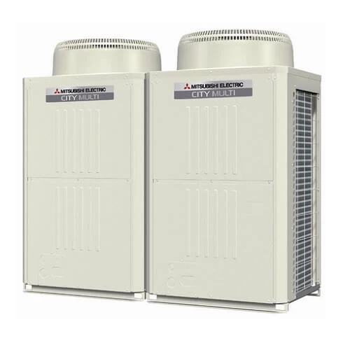
Multi City VRF
The CITY MULTI S series (for small applications) and Y series (for large applications) make use of a two-pipe refrigerant system, which allows for system changeover from cooling to heating, ensuring that a constant indoor climate is maintained in all zones.
| Error Codes | Problem |
|---|---|
| 403 | Comms fault between boards — check inverter error detail for which 2 boards, check transformer, bus voltage and inter-connecting cables |
| 900 | Lossnay unit in test run |
| 1102 | High compressor discharge temperature. Discharge temperature has exceeded 110°C or more. Short of refrigerant. Discharge thermistor |
| 1111 | Low pressure/temperature fault — check thermistors (TH2, TH3, TH4), gas charge, indoor fan, heat exchanger and filter |
| 1112 | Low pressure/temperature fault — check thermistors (TH2, TH3, TH4), gas charge, indoor fan, heat exchanger and filter |
| 1113 | Low pressure/temperature fault — check thermistors (TH2, TH3, TH4), gas charge, indoor fan, heat exchanger and filter |
| 1202 | Preliminary fault to 1102 |
| 1204 | Preliminary heat exchanger gas temperature sensor fault — check thermistors 10a and 10b |
| 1205 | Preliminary thermistor fault (TH5) |
| 1211 | Preliminary thermistor fault (TH2) |
| 1214 | Preliminary thermistor fault (THHS) |
| 1216 | Preliminary thermistor fault (TH7) |
| 1217 | Preliminary thermistor fault (TH8) |
| 1219 | Preliminary thermistor fault (TH9) |
| 1221 | Preliminary thermistor fault (TH6) |
| 1243 | Preliminary thermistor fault (TH10) |
| 1301 | Low pressure fault (63L operation) low pressure sensor sensing less than 1 bar immediately before starting |
| 1302 | High pressure fault — check pressure in system for more than 29 bar (R407c) 38 bar (R410A). Check high pressure sensor against gauge pressure |
| 1368 | Pressure sensor fault (PS1) at BC — compare pressure reading on SW1 on O/C |
| 1370 | Pressure sensor fault (PS3) at BC — compare pressure reading on SW1 at O/C |
| 1402 | Preliminary fault to 1302 |
| 1500 | System overcharge. Abnormal low compressor superheat — discharge thermistor TH4 |
| 1501 | High compressor shell temp — check for shortage of gas, insufficient indoor index running (comms room units) |
| 1505 | Suction pressure abnormal — generated by low pressure sensor detecting a vacuum — check for blockage, closed valve or sensor fault |
| 2500 | Detecting lack of water flow on a water circuit |
| 2502 | I/C has water level in drip tray, when the unit was running in cooling (temperature sensors — check for open or closed circuit and operation of pump) |
| 2503 | I/C has water level in drip tray when the unit was running in cooling (float sensor — check for closed circuit on float switch and operation of pump) |
| 2600 | Water leak from humidifier |
| 4100 | Compressor over current protection on Mr Slim with M-net interface — check inverter or compressor |
| 4101 | Compressor over current protection on Mr Slim with M-net interface — check inverter or compressor |
| 4102 | Open phase fault — check power supply and noise filter for loss of phase, check wiring and fuses |
| 4103 | Reverse phase fault — check phase rotation, loss of phase through the noise filter, fuse blown and high pressure switch open at power on |
| 4106 | Transmission power supply fault — check wiring, high current, incorrect voltage on transmission line and/or M-Net board |
| 4108 | Over current protection on DOL compressor — check power supply, contactor and compressor |
| 4115 | Power supply abnormal — check power, fuses, connections and PCB |
| 4116 | Fan motor abnormal — check fan motor and board (relates to indoor unit or Lossnay unit) |
| 4124 | Thermal switch (49C) open circuit on Mr Slim on M-Net — reset and check pressures and air flow |
| 4210 | Compressor over current problem — check inverter balance. Compressor and inverter |
| 4220 | Low inverter board BUS voltage. Less than 289VdcDC is detected. — check mains supply |
| 4225 | Low DC voltage on Vdc on fan inverter — check CNVdc for 300Vdc on diode stack and check mains power supply to outdoor unit |
| 4230 | High temperature on heat sink on inverter — check for blockages in air duct, failure of INV fan or failure of thermistor |
| 4235 | Fan inverter heat sink overheat protection. Reduced airflow through heat sink. Fan motor problem. THHS thermistor problem |
| 4240 | Over current protection. If high current is detected for more than 10 minutes — check inverter balance. Reduced airflow through heat sink |
| 4245 | Over current protection. Possible ACCT current sensor fault. Should read 280 ohms between pins 1 & 2 and across pins 3 & 4 |
| 4250 | Over current protection. Inverter IPM problem. Compressor lock — check inverter balance |
| 4255 | Inverter cooling fan problem — if high static fan is used then check that SW3-9 is on |
| 4260 | Preliminary inverter heat sink overheat protection. Reduced airflow through heat sink. Fan motor problem. THHS thermistor problem |
| 5101 | Thermistor fault at indoor/outdoor unit — check fault code address |
| 5102 | Thermistor fault at indoor/outdoor unit — check fault code address |
| 5103 | Thermistor fault at indoor/outdoor unit — check fault code address |
| 5104 | Thermistor fault at indoor/outdoor unit — check fault code address (indoor fault — check SW7-3 is off) |
| 5105 | TH5 open/short circuit — check if the TH is disconnected from the board |
| 5106 | TH6 open/short circuit — check if the TH is disconnected from the board |
| 5107 | TH7 open/short circuit — check if the TH is disconnected from the board |
| 5108 | TH8 open/short circuit — check if the TH is disconnected from the board |
| 5109 | TH9 open/short circuit — check if the TH is disconnected from the board |
| 5110 | TH10 open/short circuit — check if the TH is disconnected from the board |
| 5111 | BC box thermistor error — TH11 open/short circuit, disconnected from board/pipe |
| 5112 | BC box thermistor error — TH10 open/short circuit, disconnected from board/pipe |
| 5113 | BC box thermistor error — TH open/short circuit, disconnected from board/pipe |
| 5114 | BC box thermistor error — TH open/short circuit, disconnected from board/pipe |
| 5115 | BC box thermistor error — TH15 open/short circuit, disconnected from board/pipe |
| 5116 | BC box thermistor error — TH16 open/short circuit, disconnected from board/pipe |
| 5201 | Pressure sensor fault outdoor unit/BC box — check fault code address/SW1 pressure sensor readings |
| 5202 | Pressure sensor fault (PS2) in the BC box |
| 5203 | Pressure sensor fault (PS3) in the BC box |
| 5300 | A-Control UH fault — see Mr Slim fault code list |
| 5301 | Current sensor fault, ACCT or DCCT — check inv. error details |
| 5401 | Temperature sensor fault — check CN30 for humidity sensor |
| 5701 | Loose float switch connector — check switch, check CN4F on indoor unit |
| 6201 | TB7 transmission line communication error — check for voltage abnormality/short |
| 6202 | Transmission processor hardware error — check for noise/short on M-Net cable |
| 6600 | Repeat address fault — two or more units are assigned the same address — correct the repeated address |
| 6601 | Polarity setting error — no voltage or short circuit on the m-net transmission line |
| 6602 | Hardware error of transmission processor. Noise interference. Polarity problem on TB7 |
| 6603 | Bus circuit busy — check if indoor unit, Lossnay unit or anything else has been wired into TB7, instead of TB3 |
| 6607 | Communication issue — no response back from unit whilst system is operational |
| 6608 | Communication error — loss of voltage or noise entering the transmission line |
| 6700 | K control communication error — R22 type unit connected onto M-Net circuit comms error |
| 6701 | K control communication error — R22 type unit connected onto M-Net circuit comms error |
| 6702 | K control duplicate address error — two or more R22 type units connected onto M-Net circuit with the same address |
| 6750 | K control communication error — R22 type unit connected onto M-Net circuit comms error |
| 6751 | R22 R/A thermistor fault (P1) |
| 6752 | R22 frost protection at I/C (P6) |
| 6753 | Comms fault between O/C and I/C |
| 6754 | R22 drain fault (P5) |
| 6755 | R22 drain fault (P5) |
| 6756 | R22 frost protection at I/C (P6) |
| 6757 | System error |
| 6758 | Comms fault between I/C and O/C |
| 6761 | R22 R/A thermistor fault (P1) |
| 6762 | R22 TH2 fault check resistance (P2) |
| 6763 | R22 Comms fault between I/C and O/C |
| 6764 | R22 drain fault (P4) |
| 6765 | R22 drain fault (P5) |
| 6766 | R22 frost protection at I/C (P6) |
| 6767 | R22 comms fault between I/C and O/C |
| 6771 | K abnormality — high pressure abnormality or low pressure abnormality |
| 6772 | K abnormality — inner thermostat function, discharge temperature abnormality, shell thermostat function, over current protection |
| 6773 | K abnormality — radiator plate thermostat function |
| 6774 | K abnormality — outdoor thermistor abnormality |
| 6775 | K abnormality — pressure sensor abnormality, indoor/outdoor communication error |
| 6776 | K abnormality — over current shut-off |
| 6777 | K abnormality — system error |
| 6778 | K abnormality — normal |
| 6779 | K abnormality — refrigerant overcharge, abnormal voltage, abnormal CT sensor |
| 6830 | Comms fault between I/C and R/C check connections to MA R/C and check for 12Vdc check R/C not set sub controller |
| 6831 | MA R/C communication fault — check connections on TB15 or that the controller was removed while the I/C was powered |
| 6832 | MA controller comms fault — check cable length no bigger than 500m, check connection and type of cable used, check R/C not set sub on field settings |
| 6833 | MA controller comms fault check cable length no bigger than 500m, check connection and type of cable used, check R/C not set sub on field settings |
| 6834 | MA Controller comms fault — check cable length no bigger than 500m, check connection and type of cable used, check R/C not set sub on field settings |
| 6840 | A-Control E6/E8 fault — see Mr Slim fault code list |
| 6841 | A-Control E7/E9 fault — see Mr Slim fault code list |
| 6844 | A-Control EA fault — see Mr Slim fault code list |
| 6845 | A-Control Eb fault — see Mr Slim fault code list |
| 6846 | A-Control EC fault — see Mr Slim fault code list |
| 7100 | Over capacity — (R2 150% index exceeded) (Y 130% index exceeded) |
| 7101 | Capacity setting error — SW2 set wrong on indoors, SW5 on YHMA outdoor, (SW3-10 on older kit) |
| 7102 | Error in number of connected units — loss of M-Net voltage (short or break), no power to BC, wrong SW5 setting on box, wrong box type |
| 7105 | Address setting error — OC or BC addressed wrong |
| 7106 | Attribute setting error — SW3-1 setting on a GUF |
| 7107 | Port setting error — check if too much capacity on a single port, wiring SW2 setting, wrong SW14 setting or wrong units on a box when using multiple boxes |
| 7110 | Check SW5-7 is correctly set |
| 7111 | Remote control sensor fault — SW1 — 1 on and no controllers fitted or faulty remote controller |
| 7113 | Function setting error — wrong SW5 setting or wrong resistors fitted on YHM-A |
| 7117 | Model setting error — SW5 set wrong or wrong resistors in |
| 7130 | Incompatible equipment on M-Net — check split with MAC 399 wired onto the TB5 line TB5 line, not the TB7 |
Cassette AC

| Alarm Codes | Solutions |
|---|---|
| P1 | Intake sensor error |
| P2 | Pipe (TH2) sensor error |
| P9 | Pipe (TH5) sensor error |
| E6,E7 | Indoor/outdoor unit communication error |
| P4 | Drain sensor error/Float switch connector (CN4F) open |
| P5 | Drain pump error |
| PA | Forced compressor stop (due to water leakage abnormality) |
| P6 | Freezing/Overheating protection operation |
| EE | Communication error between indoor and outdoor units |
| P8 | Pipe temperature error |
| E4,E5 | Remote controller signal receiving error |
| Fb | Indoor unit control system error (memory error, etc.) |
| PL | Refrigerant circuit abnormal |
| E0,E3 | Remote controller transmission error |
| E1,E2 | Remote controller control board error |
| E9 | Indoor/outdoor unit communication error (Transmitting error) (Outdoor unit) |
| UP | Compressor overcurrent interruption |
| U3,U4 | Open/short of outdoor unit thermistors |
| UF | Compressor overcurrent interruption (When compressor locked) |
| U2 | Abnormal high discharging temperature/49C operated/ insufficient refrigerant |
| U1,Ud | Abnormal high pressure (63H operated)/Overheating protection operation |
| U5 | Abnormal temperature of heat sink |
| U8 | Outdoor unit fan protection stop |
| U6 | Compressor overcurrent interruption/Abnormal of power module |
| U7 | Abnormality of super heat due to low discharge temperature |
| U9,UH | Abnormality such as overvoltage or voltage shortage and abnormal synchronous signal to main circuit/Current sensor error |
Ecodan
Ecodan air source heat pumps use 1kW of electrical energy input and take 2.2kW of low temperature renewable heat energy from the air, producing a high efficient 3.2kW heat energy output. This heats refrigerant in the system which in turn heats water for domestic hot water and space heating.

| Fault Codes | Problem |
|---|---|
| F3 | Low pressure switch failure — check connection on the board and continuity of switch |
| F5 | High pressure switch failure — check connection onto board and continuity of switch |
| F9 | Both pressure switch contacts are open at the same time — check connection onto board and continuity of switch and for a potential board failure |
| EA | Mis-wiring fault between FTC and Ecodan — check S1,S2,S3 also check voltages and comms |
| EB | Mis-wiring fault between FTC and Ecodan — Check S1,S2,S3 also check voltages and comms |
| EC | Unit cannot finish start up process — generally caused by a comms fault |
| U1 | Ecodan high pressure fault — mainly caused by incorrect water flow rates — check with flow setter |
| U2 | Ecodan high compressor discharge temperature — mainly caused by refrigerant shortage or dirty condenser |
| U3 | Ecodan discharge thermistor problem — mainly caused by TH4 discharge thermistor — open/close circuit |
| U4 | Open or close circuit Ecodan thermistors (TH3, TH32, TH33, TH6, TH7, TH8) — open or close circuit or disconnected from main board |
| U5 | Inverter heat sink overheat protection (W50 and W85 models 77°C, HW140 model 95°C — reduced air flow through Ecodan — faulty fan motor |
| U6 | Inverter/Compressor over current — system indicates possible IPM error |
| U8 | Ecodan fan motor problem — mainly caused by DC fan motor being disconnected, connected or obstructed with the power on or possible main board fault |
| U9 | Over voltage or under voltage — mainly caused by either CN2 or CN5 loose or disconnected or decrease of mains power supply |
| UD | Overheat protection TH3 ≥ 70°C or 63HS ≥ 70°C saturation temperature |
| UF | Compressor over current/Compressor lock — occurs within 30 seconds of compressor start |
| UH | Abnormal running current — < 1A or > 40A detected during operation — check CN5 connections |
| UL | Open circuit (63L ) |
| UP | Over current detected after 30 seconds of operation — do an inverter test to determine outputs balanced |
| E0 | Transmitting Error PAR W21 — check refrigerant address on SW1 of Ecodan |
| E1 | Faulty controller |
| E3 | Transmitting Error (PAR W21) — check refrigerant address on SW1 of Ecodan |
| E4 | Receiving Error (PAR W21) — check refrigerant address of SW1 on Ecodan |
| E5 | Receiving Error (PAR W21) — check refrigerant address of SW1 on Ecodan |
| E6 | Indoor/Outdoor communication error — mainly due to Ecodan being powered up before FTC(2) |
| E8 | Indoor/Outdoor communication error — mainly due to Ecodan being powered up before FTC(2) |
| E9 | Indoor/Outdoor communication error — mainly due to Ecodan being powered up before FTC(2) |
| EF | Non-defined error code — noise interference — power down Ecodan for 30 seconds then switch back on |
| ED | Serial communication fault between Ecodan main board and Ecodan inverter board — mainly due to loose CN2 or CN5 cable |
| P1 | Flow temp sensor fault — TH1 not connected, short or open circuit |
| P6 | Over heating at heat exchanger — lack of water flow, air in the system, flow rate incorrectly set, blockage or pump problem |
| P8 | No temp change at plate heat exchanger — problem with flow rate (too high) — incorrect sizing of system |
| P9 | TH5 Fault — TH5 not connected, short or open circuit, FTC not configured for heating only |
| PE | Inlet water temp fault — TH32 is below 10°C whilst compressor is in operation — possible thermistor out of range, short of gas, incorrect sizing of radiator or problem in the water circuit (blockage, pump failure etc) |
Hot Water Heat Pumps PWFY Series
12.5kW Hot Water Module. Flexibility to create very large systems. Can be installed in conjunction with City Multi VRF air conditioning. Available in one size: PWFY-P100VM-E-BU (12.5kW heating) which is modular to allow creation of larger solutions. Sanitary water heating has suitable applications in: hotels and motels, apartments, commercial kitchens and laundries, office buildings, food processing industry, heat recovery from air conditioning systems into sanitary water storage, and direct sanitary water heating is also possible.
| Fault Codes | Problem |
|---|---|
| 403 | Comms fault between boards — check between control board an inverter board |
| 403 | Comms fault between boards — check between control board an fan board |
| 1102 | High compressor discharge temperature — discharge temp has exceeded 115°C or more — check if short of refrigerant or discharge thermistor |
| 1301 | Low pressure fault — low pressure sensor sensing less than 1 bar immediately before starting |
| 1302 | High pressure fault — check system pressure exceded 32.3 bar, check high pressure sensor (63HS) against gauge pressure |
| 2000 | Pump interlock error — pump interlock open whilst system in operation |
| 2134 | Abnormal water temperature (TH6) has exceded 85°C |
| 2135 | Water source heat exchanger frozen (TH6) or (TH8) reading 2°C |
| 4102 | Open phase fault — check power supply and noise filter for loss of phase, check wiring and fuses |
| 4115 | Power supply abnormal — check power, fuses, connections and PCB |
| 4220 | Low inverter board BUS voltage — less than 200Vdc is detected during in inverter operation — check mains supply |
| 4220 | Bus voltage error PAM damage — replace the inverter board |
| 4220 | High bus voltage Vdc>380v — check power supply and possible faulty inverter board |
| 4220 | Replace inverter board |
| 4230 | High temperature (85°C) on heat sink on inverter — check for blockages in air duct, failure of INV fan failure of INV fan or failure of thermistor (THHS) |
| 4250 | Over current protection — inverter IPM problem or compressor lock — check inverter balance |
| 4250 | ACCT sensor over current detection 34.5A peak or 16A rms is detected — check the compressor for failure, or possible inverter board failure |
| 5102 | Thermistor TH22 failure |
| 5103 | Thermistor TH13 or TH23 failure |
| 5104 | Thermistor TH11 failure |
| 5106 | Thermistor TH6 failure |
| 5108 | Thermistor TH8 failure |
| 5110 | Thermistor THHS failure |
| 5201 | High pressure sensor fault — check the system pressure is >1 bar, check the operation of 63HS high pressure transducer |
| 5202 | Pressure sensor fault |
| 5301 | Current sensor fault, ACCT or DCCT — check inv. error details |
| 5301 | Low output current <1.5A rms whilst the inverter is in operation |
Packaged Hot Water Heat Pump CAHV
45kW Packaged Hot Water Heat Pump. Can be combined to max. 70kW. “Flash-injection Circuit”, which is designed for our ZUBADAN CITY MULTI (air conditioning system for cold regions), is mounted in our new Hot Water Heat Pump. By utilizing our advanced “Flash-injection Circuit” and the latest high-efficiency compressor, Hot Water Heat Pump provides hot water upto 70°C, and produces less capacity drop at low outdoor temperature.
| Error Codes | Problem |
|---|---|
| AFSA | Water supply cut-off (flow switch has been triggered) — check flow switch and wiring |
| AHP1 | High pressure fault — check water flow, possible high pressure sensor fault LEV fault |
| AdSH | Compressor crank case temperature of 10°C or less for 40 minutes while compressor in operation — check for possible failure of fan motor, low pressure sensor, compressor shell thermistor, high pressure sensor, discharge thermistor (TH1 TH5), LEV or SV2 |
| 1303 | Low pressure protection low pressure below 6 bar within 30 sec of start up — possible failure of LP sensor, air inlet thermistor fault (TH4 TH8), suction temperature (TH2 TH6), LEV bypass check valve |
| 1103 | Compressor shell bottom temperature exceeded 80°C detected whilst compressor running |
| 5109 | Compressor shell thermistor faulty (TH3 TH6), LEV failure |
| 5110 | Outside temperature thermistor fault — check TH9 |
| 5112 | Water inlet temperature — check TH10 main circuit |
| 5111 | Water inlet temperature — check TH12 sub circuit |
| 5113 | Outlet water temperature — check TH11 main circuit |
| 5103 | Outlet water temperature — check TH12 sub circuit |
| 5107 | Compressor shell temperature — check TH3 main circuit |
| 5101 | Compressor shell temperature — check TH7 sub circuit |
| 5105 | Discharge temperature — check TH1 main circuit |
| 5102 | Discharge temperature — check TH5 sub circuit |
| 5106 | Inlet temperature — check TH2 main circuit |
| 5104 | Inlet temperature — check TH6 sub circuit |
| 5108 | Air to refrigerant heat exchanger inlet temperature — check TH4 main circuit |
| 5114 | Air to refrigerant heat exchanger inlet temperature — check TH8 sub circuit |
| 5115 | Common return water when using multiple outdoors — check TH14 |
| 5117 | Common return water when using multiple outdoors — check TH15 |
| 5118 | High pressure sensor or high pressure fault — check 63HS sensor or 63H (hp switch) |
| 7113 | Low pressure sensor low or low pressure fault — check 63LS |
| 7117 | Model setting error 1 — mis-set switch |
| 4115 | Model setting error 2 — faulty Z21 resistor |
| A471 | Power supply frequency fault — power supply frequency is not 50Hz or 60Hz |
| 1104 | Discharge temperature fault — 120°C detected during compressor operation — check water flow, pump, high pressure sensor fault or LEV fault |
| AC61 | Power supply fault — check transmission power supply or if PCB faulty |
MR Slim Operation Light Blinking
Flashing of POWER lamp indicates abnormalities. Before taking measures, make sure that the symptom reappears for accurate troubleshooting. Self check table
When the indoor unit has started operation and the above detection method has detected an abnormality (the first detection after the power ON), the indoor electronic control P.C. board turns OFF the indoor fan motor with OPERATION INDICATOR lamp flashing.
| Indicator lamp | Solution |
|---|---|
| POWER lamp flashes. 0.5-second ON | Mis-Wiring or serial signal. Outdoor unit does not operate. When the serial signal form the outdoor unit is not received for a maximum of 6 minutes. |
| POWER lamp lights up | Out door control system. Outdoor unit does not operate. When it cannot properly read data in the nonvolatile memory of the inverter P.C. board or the outdoor electronic control P.C. board. Check the blinking pattern of the LED on the inverter P.C. board or the outdoor lectronic control P.C. board. |
| POWER lamp flashes. 2-time flash | Indoor coil thermistor. Room temperature thermistor. Indoor unit and outdoor unit do not operate. When the indoor coil or the room temperature thermistor is short or open circuit. |
| POWER lamp flashes. 3-time flash | Indoor fan motor. Indoor unit and outdoor unit do not operate. When the rotational frequency feedback signal is not emit during the indoor fan operation. |
| POWER lamp flashes. 5-time flash | Out door power system. Indoor unit and outdoor unit do not operate. When it consecutively occurs 3 times that the compressor stops for overcurrent protection or start-up failure protection witth in 1 minute after start-up. |
| POWER lamp flashes. 6-time flash | Outdoor thermistors. Indoor unit and outdoor unit do not operate. When the outdoor thermistors short or open circuit during the compressor operation. |
| POWER lamp flashes. 7-time flash | Out door control system. Indoor unit and outdoor unit do not operate. When it cannot properly read data in the nonvolatile memory of the inverter P.C. board or the outdoor electronic control P.C. board. |
| POWER lamp flashes. 14-time flash | Other abnonmality. Indoor unit and outdoor unit do not operate. An abnormality other than above mentioned is deteced. Confirm the abnormarity in detail using the failure mode recall function. |
Split AC Timer Light Blinking
| Trouble | Contents |
|---|---|
| 3 blinking-1 blinking | Abnormality of comp. surface thermistor (TH32) and discharging temperature (TH4) |
| 3 blinking-2 blinking | Abnormal high pressure (High pressure switch 63H operated.) |
| 3 blinking-3 blinking | Abnormality of outdoor fan motor rotational speed. Protection from overheat operation(TH3). |
| 3 blinking-4 blinking | Compressor overcurrent breaking (Start-up locked). Compressor overcurrent breaking. Abnormality of current sensor (P.B.). Abnormality of power module. |
| 3 blinking-5 blinking | Open/short of discharge thermistor (TH4) and comp. surface thermistor (TH32). Open/short of outdoor thermistors (TH3, TH6, TH7 and TH8). |
| 3 blinking-6 blinking | Abnormality of heatsink temperature |
| 3 blinking-7 blinking | Abnormality of voltage |
| 4 blinking-1 blinking | Abnormality of room temperature thermistor (TH1). Abnormality of pipe temperature thermistor /Liquid (TH2). Abnormality of pipe temperature thermistor/Condenser-Evaporator. |
| 4 blinking-2 blinking | Abnormality of drain sensor (DS) Float switch(FS) connector open. Indoor drain overflow protection. |
| 4 blinking-3 blinking | Freezing (cooling)/overheating (heating) protection |
| 4 blinking-4 blinking | Abnormality of pipe temperature |
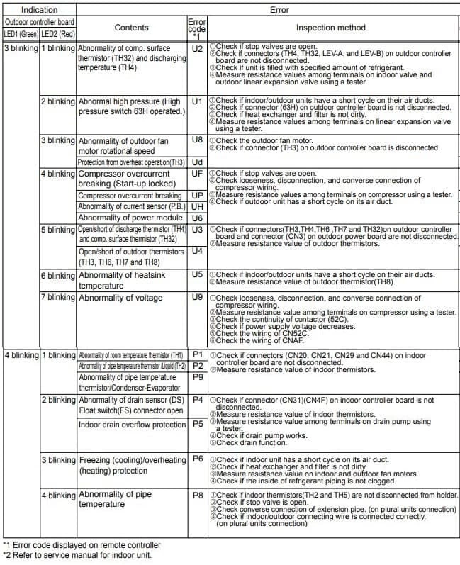
Aircon RedLINK Codes
| Error Codes | Meaning |
|---|---|
| E0 27 | Verify device temperature is within operating range. If within range for at least 30 minutes and problem persists, replace Remote Controller. |
| E0 91 | Communication was established between wireless receiver and the indoor unit, but communication has been lost for 10 minutes. Check cable connection. Try replacing the cable. |
| E1 29 | Attempting to connect incompatible wireless devices. |
| E1 34 | Low signal strength. Move wireless device to a different location and try again. |
| E1 38 | Make sure Connect light on wireless receiver is flashing and you are 2+ feet away from wireless receiver. |
| E1 54 | Indoor unit does not support wireless receiver. |
Troubleshooting
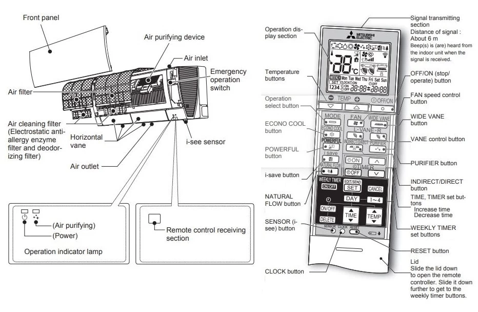
Even if these items are checked, when the unit does not recover from the trouble, stop using the air conditioner and consult your dealer.
Symptom: The unit cannot be operated.
Explanation & Check points:
- Is the breaker turned on?
- Is the power supply plug connected?
- Is the ON timer set?
Symptom: The horizontal vane does not move.
Explanation & Check points:
- Are the horizontal vane and the vertical vane installed correctly?
- Is the fan guard deformed?
- When the breaker is turned on, the horizontal vanes’ position will be reset in about a minute. After the reset has completed, the normal horizontal vanes’ operation resumes. The same is true in the emergency cooling operation.
Symptom: The airfl ow direction changes during operation. The direction of the horizontal vane cannot be adjusted with the remote controller.
Explanation & Check points:
- When the unit is operated in COOL or DRY mode, if the operation continues with air blowing down for 0.5 to 1 hour, the direction of the airfl ow is automatically set to horizontal position to prevent water from condensing and dripping.
- In the heating operation, if the airfl ow temperature is too low or when defrosting is being done, the horizontal vane is automatically set to horizontal position.
Symptom: Water leaks from the outdoor unit.
Explanation & Check points:
- During COOL and DRY operations, pipe or pipe connecting sections are cooled and this causes water to condense.
- In the heating operation, water condensed on the heat exchanger drips down.
- In the heating operation, the defrosting operation makes ice forming on the outdoor unit melt and drip down.
Symptom: The display on the remote controller does not appear or it is dim. The indoor unit does not respond to the remote control signal.
Explanation & Check points:
- Are the batteries exhausted?
- Is the polarity (+, -) of the batteries correct?
- Are any buttons on the remote controller of other electric appliances being pressed?
Symptom: The room cannot be cooled or heated sufficiently.
Explanation & Check points:
- Is the temperature setting appropriate?
- Is the fan setting appropriate? Please change fan speed to High or Super High.
- Are the fi lters clean?
- Is the fan or heat exchanger of the indoor unit clean?
- Are there any obstacles blocking the air inlet or outlet of the indoor or outdoor unit?
- Is a window or door open?
- It may take a certain time to reach the setting temperature or may not reach that dependingon the size of the room, the ambient temperature, and the like.
Symptom: The air from the indoor unit smells strange.
Explanation & Check points:
- Are the fi lters clean?
- Is the fan or heat exchanger of the indoor unit clean?
- The unit may suck in an odor adhering to the wall, carpet, furniture, cloth, etc. and blow it out with the air.
Symptom: Weekly timer does not operate according to settings.
Explanation & Check points:
- Is the ON/OFF timer set?
- Transmit the setting information of the weekly timer to the indoor unit again. When the information is successfully received, a long beep will sound from the indoor unit. If information fails to be received, 3 short beeps will be heard. Ensure information is successfully received.
- When a power failure occurs and the main power turns off, the indoor unit built-in clock will be incorrect. As a result, the weekly timer may not work normally.
Electrical Wiring Diagram

Refrigerator Diagram
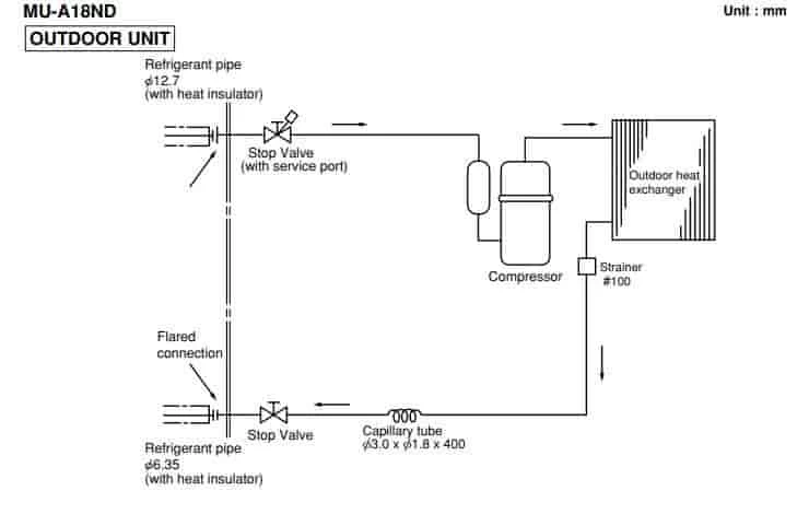
Manuals PDF
Mitsubishi Air Conditioning Service Handbook PDF
Mitsubishi Air Conditioning Service Manual PDF
Mitsubishi Electric MRCH1 Remote ControllerOperating Manual PDF
Mitsubishi Electric Split AC Manual MSZ-AP22VGD PDF
Mhk1 Wireless Remote Receiver Kit Manual PDF
MIFH1, MRCH1, MCCH1, MOS1 Controller Kit Installation Manual PDF
Mitsubishi Air Conditioning Error Codes PDF – R410A Systems
- Author
- Recent Posts

Regarding error and fault codes, we believe sharing knowledge is the best way to help everyone. That is why we established ACErrorCode.com, to give you every bit of info you need as a customer. HVAC Expert Contact: dannyreese@acerrorcode.com
![]()
*If you can’t find the code you’re looking for on our site, please let us know, and we’ll update our database as soon as possible.