

— 33 —
423*
«Отклонение термостата инвертора от нормы — Инвертор №: *»
4240
«Максимальная токовая защита инвертора (защита от перегрузки)»
424*
«Максимальная токовая защита инвертора — Инвертор №: *»
4250
«Аномальный уровень напряжения ИСМ инвертора / шины» / Отклонение модуля питания от нормы (A)
425*
«Отклонение ИСМ инвертора от нормы *»
4260
«Нарушение работы охлаждающего вентилятора инвертора»
426*
«Нарушение работы охлаждающего вентилятора инвертора — Инвертор №: *»
4300
«Выход параметров инвертора за допустимые пределы»
430*
«Выход параметров инвертора за допустимые пределы — Инвертор №: *»
4310
«Пределы отключения инвертора по максимальному току»
431*
«Пределы отключения инвертора по максимальному току — Инвертор №: *»
4320
«Выход за нижний предел уровня напряжения в шине инвертора»
432*
«Низкий уровень напряжения в шине инвертора — Инвертор №: *»
4330
«Выход параметров термостата инвертора за допустимые пределы»
433*
«Выход параметров термостата инвертора за допустимые пределы — Инвертор №: *»
4340
«Отклонение от нормы максимальной токовой защиты инвертора»
434*
«Отклонение от нормы максимальной токовой защиты инвертора — Инвертор №: *»
4350
«Выход параметров ИСМ инвертора за допустимые пределы»
435*
«Выход параметров ИСМ инвертора за допустимые пределы *»
4360
«Предварительное нарушение работы охлаждающего вентилятора инвертора»
436*
«Предварительное нарушение работы охлаждающего вентилятора инвертора — Инвертор №: *»
5000
«Нарушение работы датчика»
50*0
«Нарушение работы датчика в системе *»
51**
«Нарушение работы датчика температуры — Датчик №: **»
5202
Разомкнут разъем (63L) (A)
52**
«Нарушение работы датчика давления — Датчик №: **»
5300
Отклонение датчика тока от нормы (A)
53**
«Нарушение работы датчика тока — Датчик №: **»
54**
«Нарушение работы датчика влажности — Датчик №: **»
55**
«Нарушение работы датчика газа — Датчик №: **»
56**
«Нарушение работы датчика скорости потока воздуха — Датчик №: **»
57**
«Нарушение работы концевого выключателя — Выключатель №: **»
58**
«Нарушение работы датчика — Датчик №: **»
59**
«Нарушение работы других датчиков — Датчик №: **»
6000
«Отклонение системы от нормы»
6101
«Система не функционирует из-за отклонения кадра отклика от номы»
6102
«Отсутствует отклик»
6200
«Отклонение аппаратного обеспечения контроллера от нормы»
6201
«Сбой ЭСППЗУ»
6202
«Сбой системных часов»
6500
«Ошибка связи»
6600
«Ошибка связи — Дублирование адреса»
6601
«Ошибка связи — Неустановившаяся полярность»
6602
«Ошибка связи — Ошибка аппаратного обеспечения процессора передачи данных»
6603
«Ошибка связи — Линия передачи данных занята»
6604
«Ошибка связи — Отсутствует подтверждение приема (06H) (ошибка цепи связи)»
6605
«Ошибка связи — Отсутствует кадр отклика»
6606
«Ошибка связи — Ошибка связи процессора передачи данных»
6607
«Ошибка связи — Отсутствует возврат подтверждения приема»
6608
«Ошибка связи — Отсутствует возврат кадра отклика»
6609
«Ошибка связи»
6610
«Ошибка связи»
6700
«Ошибка связи — Сбой передачи данных линии связи K»
6701
«Ошибка связи — Ошибка передачи данных линии связи K»
6702
«Ошибка связи — Дублирование K-адреса»
6750
«Ошибка связи — Код ошибки сбоя линии K»
6751
«Отклонение от нормы линии K — Отклонение термистора комнатной температуры от нормы»
6752
«Отклонение от нормы линии K — Отклонение от нормы термистора внутреннего змеевика, отклонение от нормы датчика температуры конденсации»
6753
«Отклонение от нормы линии K — Ошибка передачи/приема»
[7-8 Error Code Definitions and Solutions: Codes [6000 — 6999] ]
7-8-15
1. Error code definition
No ACK error
2. Error definition and error detection method
The error is detected when no acknowledgement (ACK signal) is received after the transmission. (eg. When the data is trans-
mitted six times in a row with 30 seconds interval, the error is detected on the transmission side.)
The address/attribute appeared on the display on the remote controller indicates the controller which did not provide
the response (ACK).
3. Cause, check method and remedy
(1)
Although the address of ME remote controller has been
changed after the group is set using ME remote control-
ler, the indoor unit is keeping the memory of the previous
address. The same symptom will appear for the registra-
tion with SC.
(2)
Although the address of LOSSNAY has been changed af-
ter the interlock registration of LOSSNAY is made using
ME remote controller, the indoor unit is keeping the mem-
ory of the previous address.
HWE13080
Cause
— 233 —
Check method and remedy
Delete unnecessary information of non-existing
address which some indoor units have.
Use either of the following two methods for dele-
tion.
1)
Address deletion by ME remote controller
Delete unnecessary address information using the
manual setting function of ME remote controller.
For details, refer to the following page(s). [6-3-4
Address Deletion](page 154)
2)
Deletion of connection information of the outdoor
unit by the deleting switch
Note that the above method will delete all the
group settings set via the ME remote controller and
all the interlock settings between LOSSNAY units
and indoor units.
Procedures
1)
Turn off the power source of the outdoor unit,
and wait for 5 minutes.
2)
Turn on the dip switch (SW5-2) on the outdoor
unit control board.
3)
Turn on the power source of the outdoor unit,
and wait for 5 minutes.
4)
Turn off the power source of the outdoor unit,
and wait for 5 minutes.
5)
Turn off the dip switch (SW5-2) on the outdoor
unit control board.
6)
Turn on the power source of the outdoor unit.
GB
Кондиционеры Mitsubishi-Electric | Неисправности сплит-систем, коды ошибок
Кондиционеры Mitsubishi-Electric | Неисправности сплит-систем, коды ошибок
Кондиционеры Mitsubishi-Electric, ошибки R410A
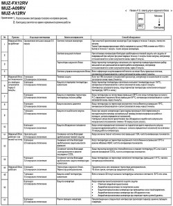
Таблица неисправности сплит систем Mitsubishi-Electric
Из чего состоит ошибка

Коды ошибок компьютерной диагностики в работе авто Митсубиси состоят из пяти символов.
Первый буквенный символ значит:
Второй знак обозначает:
Третий указывает на конкретную систему:
Последние два знака определяют порядковый номер неполадки.
Премиум объявления

Продаются анемостаты для систем вентиляции — ламельные круглые и квадратные анемостаты. А так же широкий ассортимент анемостатов для приточно-вытяжных систем вентиляции.
Продаются анемостаты для систем вентиляции — ламельные круглые и квадратные анемостаты. А так же широкий ассортимент анемостатов для приточно-вытяжных систем вентиляции.

У нас есть широкий ассортимент воздуховодов различных диаметров и из различных материалов.
Так что если вам нужно купить воздуховоды Звоните НАМ и вы точно найдете то, что вам нужно!

Продается ТЭН подогрева масла в компрессорах, и много других запасных частей для кондиционеров.

Оригинальные термостаты для систем кондиционирования
ПРОДАЮТСЯ:
погружной термостат
комнатный электронный термостат WFHT (с дисплеем и без)
накладной термостат И другие

Наша компания занимается установкой и профилактическим обслуживанием отопительных котлов в Ташкенте и Ташкентской области.
Ремонт стиральных и посудомоечных машин в Ташкенте. А так же любой крупной бытовой техники.

Колонные кондиционеры Galanz — качество и надежность по низким ценам!
Мы предлагаем широкий выбор кондиционеров колонного типа по самым низким ценам в Ташкенте.
Galanz AUF-24D2 — 24.000 BTU
Galanz AUF-48D2 — 48.000 BTU
Galanz AUF-60D2 — 60.000 BTU

Продаем гликолевые манометры Cold Gauge (Нидерланды), в наличии есть модели на низкое и высокое давление.
В наличии на складе в Ташкенте:
Cold Gauge 202 — манометр высокого давления, гликолевый, выход штуцера снизу, 6 мм.
Цена: 124.000 сум.

Продаем качественные и надежные манометры Cold-Gauge (Нидерланды).
Манометры предназначены для использования в холодильной технике.
В наличии на складе в Ташкенте есть:
COLDGAUGE 101 — глицериновый манометр низкого давления, выход штуцера сзади, 6 мм.

#Тел: +998(97) 777-39-66 #КУПЛЮ (Сотиб оламан!)
Б/У Телевизоры, Холодильники, Морозильники, Швейные машинки, Оверлоки, Газплиты, Кондиционеры. Муз-центры. #Ташкент С Выездом. (Рабочий и Нерабочий)

#Тел: +998(97) 777-39-66 #КУПЛЮ (Сотиб оламан!)
Б/У Микровольновка, Телевизоры, Холодильники, Морозильники, Швейные машинки, Оверлоки, Газплиты, Кондиционеры. Муз-центры. #Ташкент С Выездом. (Рабочий и Нерабочий)

КУПЛЮ (Сотиб оламан!)
Б/У Телевизоры, Холодильники, Морозильники, Швейные машинки, Оверлоки, Газплиты, Кондиционеры. Муз-центры. #Ташкент С Выездом. (Рабочий и Нерабочий) #Тел: +998(97) 777-39-66
Качественная установка кондиционеров сплит систем. Быстро, надежно и не дорого.
*Предоставляется гарантия на монтажные работы.
Качественный ремонт настенных сплит систем, диагностика, замена запчастей и профилактическое обслуживание настенных кондиционеров
Качественный ремонт кондиционеров мульти сплит систем, диагностика, замена запчастей, ГАРАНТИЯ.
Диагностика и ремонт бытовых кондиционеров всех видов, качественно, быстро и не дорого.
Ремонт чиллеров, фанкойлов, мультизональных систем кондиционирования, прецизионных кондиционеров и т. д. У нас работают специалисты с большим стажем работы и огромным опытом в области систем кондиционирования. Более подробная информация по телефону.
Наша компания выполняет монтаж различных систем вентиляции для коттеджей, загородных домов, квартир, офисов, ресторанов, бассейнов и других объектов.
Проектирование систем вентиляции и кондиционирования, а также монтаж вентиляционных систем и пуско-наладка.
Мы осуществляем только качественный монтаж систем вентиляции, поэтому даем гарантию на все работы.
Если у вас появилась потребность в диагностике вашей системы вентиляции в помещении или здании, обратитесь, пожалуйста, в сервисный центр компании “Server Service”
Наши специалисты оперативно обработают вашу заявку относительно диагностики системы вентиляции.
Для получения полноценного, качественного и постоянного сервисного обслуживания вентиляционных систем, обращайтесь в компанию “Server Service”.
Заявки принимаются с понедельника по субботу с 9:00 до 18:00
Диагностика автомобилей
Автомобили японского производства Mitsubishi оборудованы бортовым компьютером и системой самодиагностики, что позволяет автовладельцу оперативно определить неисправность. Чтобы произвести диагностику бортового компьютера на предмет ошибок, вам понадобится специальное для этого оборудование или обычный вольтметр.
 Автомобиль Mitsubishi Lancer
Непосредственно диагностический разъем расположен в салоне транспортного средства, под приборной панелью рядом с блоком предохранителей. Подключив вольтметр к данному разъему, можно произвести диагностику разных систем Mitsubishi. В зависимости от модели авто, под приборной панелью могут быть расположены и другие разъемы для диагностики.
 Красной стрелкой указано место, где находится разъем для диагностики автомобиля Mitsubishi
Число таких импульсов совпадает со значением десятком в двузначном коде ошибки. Здесь же стоит отметить — все коды неисправностей, которые были зафиксированы компьютером, будут показываться вольтметром в порядке возрастания.
Диагностика автомобилей
Автомобили японского производства Mitsubishi оборудованы бортовым компьютером и системой самодиагностики, что позволяет автовладельцу оперативно определить неисправность. Чтобы произвести диагностику бортового компьютера на предмет ошибок, вам понадобится специальное для этого оборудование или обычный вольтметр.
Автомобиль Mitsubishi Lancer
Непосредственно диагностический разъем расположен в салоне транспортного средства, под приборной панелью рядом с блоком предохранителей. Подключив вольтметр к данному разъему, можно произвести диагностику разных систем Mitsubishi. В зависимости от модели авто, под приборной панелью могут быть расположены и другие разъемы для диагностики.
Красной стрелкой указано место, где находится разъем для диагностики автомобиля Mitsubishi
Число таких импульсов совпадает со значением десятком в двузначном коде ошибки. Здесь же стоит отметить — все коды неисправностей, которые были зафиксированы компьютером, будут показываться вольтметром в порядке возрастания.
Коды мультизональных кондиционеров бытовой серии
Бытовая мультизональная серия — это мульти сплит системы, т. к. кондиционеры, которые с одним внешним блоком способны охлаждать сразу несколько помещений.
| Символы | Описание |
|---|---|
| M |
M — серия M |
| X |
X — наружный блок для мульти сплит систем «охлаждение и нагрев» |
| Z | Z — инвертор «охлаждение и нагрев» |
| 2, 3, 4. | Максимальное количество блоков, подключаемых к кондиционеру |
| D | Подсерия |
| 33, 40, 54, 72. | Индекс номинальной производительности |
| V, Y | V — электропитание 220-50-1 Y — электропитание 380-50-3 |
| A | A — хладагент R410, система управления «new A-control» |
Пример расшифровки кода мульти сплит системы.
| Модель кондиционера | Расшифровка |
|---|---|
| MXZ-2D40VA | Инверторная мульти сплит система Mitsubishi Electric на 2 внутренних блока с мощностью охлаждения 2,0 кВт. на 410-м фреоне с подключением на 220V |
| MXZ-3D68VA | Инверторная мульти сплит система Mitsubishi Electric на 3 внутренних блока с мощностью охлаждения 6,8 кВт. на 410-м фреоне с подключением на 220V |
Промышленные кондиционеры Mitsubishi Electric
В линейке промышленных кондиционеров Mitsubishi Electric – мультизональные системы VRF-City Multi с подключением большого количества внутренних блоков, успешно применяемые для кондиционирования воздуха в крупных помещениях и многоэтажных зданиях.
Компания предлагает несколько серий VRF-City Multi:
К наружным блокам можно подключать внутренние модули разных модификаций: канальные, кассетные, настенные, напольные, подвесные.
Все промышленные кондиционеры бренда Mitsubishi Electric отличаются увеличенным метражом трассы с большими перепадами высот между внутренними блоками системы.
Климатическое оборудование от популярного японского производителя Mitsubishi Electric характеризуется длительным сроком безупречной службы при условии своевременного проведения ТО согласно рекомендациям производителя.
Mitsubishi L200 ошибка U1102 ASC/CAN
#1 kalina
Здравствуйте! История такая: приехал L200 АКПП c проблемой очень тугого переключения селектора. Причиной был напрочь закисший шток переключения в самой АКПП. Еле расшевелили, долго размачивали WD-шкой. Чтоб отмочить всё, пришлось со штока снять датчик положения (или как он там называется). Разъем с датчика не отсоединялся, как снял, так и поставил. Селектор стал работать замечательно, хозяин признался что даже при покупке (машина покупалась с рук год назад) так легко не переключалось. Уехал счастливый. А на следующий день вернулся с горящим чеком. Ошибка U1102 ASC/CAN. Покурил интернет. Ошибка вроде бы трактуется как нарушение связи с АКПП. Но жалоб на поведение машины нет, всё как обычно, всё включается и выключается, селектор прекрасно отрабатывает во всех положениях, индикатор чётко показывает в каком положении рычаг. Со сканера сбросить ошибку не получается. Сбросить получилось только снятием клеммы с АКБ минут на 15. Как оказалось, ненадолго, чек опять загорелся.
Подскажите, с чем может быть связана данная ошибка, и как вылечить?
#2 Alez
это нормально, не обращай внимание.
если бы на мешалке была — еще бы ошибка была, кан акпп.
Нормальное это явление
Сообщение отредактировал Alez: 30 May 2016 — 17:30
#3 gred
#4 Alez
дилерский, так же и будет ругаться.
#5 Ruslan021087
Тут у людей тоже такая проблема.
Нужно найти мануал, в любом мануале заводском есть алгоритмы зажигания тех или иных ошибок. И от них копать.
#6 kalina
Тут у людей тоже такая проблема.
Нужно найти мануал, в любом мануале заводском есть алгоритмы зажигания тех или иных ошибок. И от них копать.
На форумах читал, да есть такое на L200 что висит эта ошибка. Но одно дело что она висит и никому не мешает, а другое дело когда она не просто висит, а еще и чек горит, глаза мозолит. Тем более до ремонта этого не было.
#7 Vivater
Здравствуйте! История такая: приехал L200 АКПП c проблемой очень тугого переключения селектора. Причиной был напрочь закисший шток переключения в самой АКПП. Еле расшевелили, долго размачивали WD-шкой. Чтоб отмочить всё, пришлось со штока снять датчик положения (или как он там называется). Разъем с датчика не отсоединялся, как снял, так и поставил. Селектор стал работать замечательно, хозяин признался что даже при покупке (машина покупалась с рук год назад) так легко не переключалось. Уехал счастливый. А на следующий день вернулся с горящим чеком. Ошибка U1102 ASC/CAN. Покурил интернет. Ошибка вроде бы трактуется как нарушение связи с АКПП. Но жалоб на поведение машины нет, всё как обычно, всё включается и выключается, селектор прекрасно отрабатывает во всех положениях, индикатор чётко показывает в каком положении рычаг. Со сканера сбросить ошибку не получается. Сбросить получилось только снятием клеммы с АКБ минут на 15. Как оказалось, ненадолго, чек опять загорелся.
Подскажите, с чем может быть связана данная ошибка, и как вылечить?
То что коробка не в аварии это не факт. При данном типе кода( превышено время ожидания ответа от АКПП) аварийного режима не будет. Опять же, если авто не укомплектовано той или иной системой, наличие кода по шине не является нормой. Проверяйте проводку.
#8 kalina
Отпишусь по теме, может кому пригодится. Проводка там не при чём, там всё в порядке. На всякий случай очистителем контактов прочистил все разъёмы. Дело было в регулировке положения датчика, или как его ещё называют, ингибитора. Под болтами есть небольшие прорези, позволяющие подвигать датчик вокруг оси. Для определения правильного положения надо совместить отверстие в рычажке, с отверстием в корпусе датчика, можно вставить подходящее свёрлышко. Прошла неделя, жалоб нет, полёт нормальный.
Прикрепленные файлы
Сообщение отредактировал kalina: 09 June 2016 — 20:33
Re: mitsubishi 6607 error
I took a quick look at the tech manual for a Mitsubishi PUHY c/u and it looks like a communication error with lots of choices for the error. I have never had that error so I wish you luck in finding it. If you don’t have the tech manual for the system you are working on you can probably find it here in pdf form.
Источники:
https://auto-park24.ru/remont/mitsubisi-elektrik-kody-oshibok. html
Содержание статьи:
- Система самодиагностики кондиционера
- Коды ошибок для всех марок кондиционеров и сплит систем
- Mitsubishi electric ошибка e6 — Автогностика
- Расшифровка популярных кодов ошибок Mitsubishi: описание и фото
- Ошибка P0705 — пошаговое руководство по диагностике и ремонту
- Болезнь Мицубиси — ошибка P0170. Как не поменять | АвтобурУм
- Отрегулируйте датчик селектора
- Подключите автомобильное зарядное устройство
Система самодиагностики кондиционера
Некоторые неисправности владелец может устранить самостоятельно, другие же требуют вмешательства опытного специалиста из сервисного центра. Определить причину неисправности и необходимость вызова мастера помогут коды ошибок.
Где отображаются коды ошибок (в зависимости от модели кондиционера):
- На дисплее прибора.
- На пульте дистанционного управления.
- Светодиодами на блоке. В нормальном режиме они горят ровным светом. Если в работе техники произошел сбой, светодиоды мигают с небольшими перерывами.
Для определения поломки по коду ошибки владельцу нужно изучить расшифровку символов.

Если же двигатель слишком долго тормозит, то необходимо проверить в меню преобразователя настройки такого параметра, как ограничение перенапряжения, и убедиться в правильности подключения тормозного резистора.
Какой бензин выгоднее?
А92А95
Коды ошибок для всех марок кондиционеров и сплит систем
Классификация и расшифровка кодов неисправностей кондиционера
“Холодильная система не функционирует из-за срабатывания защиты от создания вакуума на всасывании компрессора / пониженной температуры хладагента”
Mitsubishi electric ошибка e6 — Автогностика
В инструкции по эксплуатации кондиционеров публикуется информация о кодах, что позволит владельцу определить тип и сложность поломки. Если у вас мало знаний об автомобилях, вы всё равно можете прочитать это, чтобы получить представление, как это делается.
Как рассчитать стоимость ОСАГО самостоятельно? Подбор самой выгодной страховки:
Рассчитать стоимость
Расшифровка популярных кодов ошибок Mitsubishi: описание и фото
- «А» и «В» – неисправности внутреннего блока;
- «Е», «Н», «F», «J», «L», «P» – проблемы возникли в наружном блоке;
- «U» и «M» – эти коды сигнализируют о проблемах системы.
В общем случае при возникновении неисправностей в работе преобразователя частоты следует обратить внимание на температуру двигателя и сообщения на экране, а также обратиться к руководству по эксплуатации. F2 Отключился термодатчик теплообменника внешнего модуля.
10 типичных проблем с частотными преобразователями “Отклонение давления холодильной системы от нормы – Общий операнд: **” По буквенным символам определяется место, где произошел сбой, а по цифре или количеству миганий диода можно определить, какая именно поломка произошла. Также эти значения применимы и для аппаратов RAS-10SKHP-ES, RAS-13SKHP-ES, RAS-13S2AH-ES, RAS-07S2AH-ES, RAS-10S2AH-ES, RAS-07SKHP-ES и других.
Сколько стоит ОСАГО на ваш автомобиль?
Поможем узнать стоимость и оформить полис без переплат с учетом скидок за КБМ! · Выбор лучшей цены. Скидка 50%. Официальный полис. Экономия времени. Узнайте цену страховки. Экономия до 3500 ₽.
Калькулятор
В общем случае при возникновении неисправностей в работе преобразователя частоты следует обратить внимание на температуру двигателя и сообщения на экране, а также обратиться к руководству по эксплуатации.
Ошибка P0705 — пошаговое руководство по диагностике и ремонту
Их число может доходить до нескольких десятков, что позволяет точнее настраивать работу преобразователя и диагностировать неисправности. Следует отметить, что в отличие от традиционной диагностики авто при помощи спецоборудования, при самостоятельной проверке на вольтметре коды ошибок будут двузначными.
Болезнь Мицубиси — ошибка P0170. Как не поменять | АвтобурУм
Если же двигатель слишком долго тормозит, то необходимо проверить в меню преобразователя настройки такого параметра, как ограничение перенапряжения, и убедиться в правильности подключения тормозного резистора. Этот механизм также подлежит очистке от пыли и прочих загрязнений.
Наиболее частые ошибки преобразователей Mitsubishi D700 : Основной разъем
1 — MPI
2 — EPS
3 — ECS
4 — ABS
5 — ASC
6 — ELC A/T
7 — A/С
8 — SRS
9 — ETACS
10 — DCT
11 — VSS
12 — GND «масса» Коды неисправностей кондиционеров классифицируются по общепринятой системе комбинирования символов и состоят из 2-3 и более знаков. Непосредственно диагностический разъем расположен в салоне транспортного средства, под приборной панелью рядом с блоком предохранителей.
В общем случае при возникновении неисправностей в работе преобразователя частоты следует обратить внимание на температуру двигателя и сообщения на экране, а также обратиться к руководству по эксплуатации.
Отрегулируйте датчик селектора
Если двигатель более-менее начал работать, то обороты гуляют вплоть до того момента, пока движок не прогрелся до температуры градусов 60. При этом все коды ошибок кондиционеров Gree можно наблюдать либо на экране пульта ДУ, либо на дисплее внутреннего блока агрегата.
Подключите автомобильное зарядное устройство
- Код E0 — ошибка подключения внутреннего и наружного блоков.
- Код Е1 — ошибка в работе внутреннего блока. Нарушение связи с контроллером.
- Код Е2 — ошибка в работе температурного датчика.
- Код Е3 — температурный датчик конденсаторной трубки неисправен.
- Код Е8 — нарушения в работе системы обогрева.
- Код F0 — ошибка в работе внутреннего вентилятора.
- Код F2 — сработала система внешней защиты.
- Код F3 — сработала защита в системе высокого давления.
- Код F4 — сработала защита в системе низкого давления.
- Код F5 — сработала защита от переполнения водой.
- Код F8 — сработала защита от перегрева наружного блока.
- Код F9 — неправильная последовательность фаз. Ошибка в системе.
- Код P4 — компрессор инверторного кондиционера неисправен.
- Код P6 — ошибка в работе наружного блока EEPROM.
Если же двигатель слишком долго тормозит, то необходимо проверить в меню преобразователя настройки такого параметра, как ограничение перенапряжения, и убедиться в правильности подключения тормозного резистора. Холодильная система Предварительная ошибка избытка хладагента.
Самостоятельная диагностика Когда селектор находится в каком-либо положении, вы должны получить соответствующее значение от датчика. Проверьте все положения, чтобы убедиться в правильности показаний. Но если уже придется добраться до газораспределительного механизма, необходимо поменять ГРМ с сопутствующим ремкомплектом. Поскольку вместо кнопки на пульте видно только отверстие, то для нажатия утопленной кнопки можно использовать канцелярскую скрепку, если ее разогнуть, или небольшой гвоздик.
-
Page 1
2017 AIR CONDITIONER Service Handbook Model PUHY-P250YNW-A PUHY-P500YSNW-A PFD-P250VM-E PFD-P500VM-E… -
Page 2
Safety Precautions Thoroughly read the following safety precautions prior to installation. Observe these precautions carefully to ensure safety. Incorrect handling can result in death or serious injury. Incorrect handling can result in minor injury or structure damage. After reading this manual, pass the manual on to the end user to retain for future reference. The user should keep this manual for future reference and refer to it as necessary. -
Page 3
To reduce the risk of shorting, current leak- Do not touch the electrical parts with bare age, electric shock, malfunctions, smoke, or hands during and immediately after opera- fire, do not splash water on electric parts. tion. To reduce the risk of electric shock, mal- Keep the space well ventilated. -
Page 4
The unit must be periodically inspected by a dealer or qualified personnel. If dust or dirt accumulates inside the unit, the drain pipes may become clogged, and water leakage from the pipes may wet the surroundings and generate odours. [2] Transportation and Installation Transportation and Installation Lift the unit by placing the slings at desig- nated locations. -
Page 5
[4] Piping Work Piping Work Operate the service valves carefully. Refrig- To prevent refrigerant leakage that can pose erant may spurt out and cause frost bite or a risk of oxygen starvation, use the flare nut other injuries. If leaked refrigerant comes in with a hole (supplied with refrigerant ser- contact with an open flame, toxic gas may vice valve) to make flare connections. -
Page 6
[5] Wiring Work Wiring Work To reduce the risk of wire breakage, over- Only use properly rated breakers (an earth heating, smoke, and fire, keep undue force leakage breaker, local switch <a switch + from being applied to the wires. fuse that meets local electrical codes>, or overcurrent breaker). -
Page 7
[7] Additional Precautions Additional Precautions Be sure to recover the refrigerant from the unit in accordance with local regulations before disposing of the unit. Provide a maintenance access hole on the piping in the ceiling and underground pip- ing. Take appropriate measures against electri- cal noise interference when installing the unit in hospitals or radio communication fa- cilities. -
Page 8: Table Of Contents
CONTENTS Chapter 1 Check Before Servicing Preparation for Piping Work……………………1 Handling and Characteristics of Piping Materials, Refrigerant, and Refrigerant Oil ……. 3 Working with Refrigerant Piping………………….8 Precautions for Wiring ……………………. 12 Cautionary notes on installation environment and maintenance………… 14 Chapter 2 Restrictions System Configurations ……………………..
-
Page 9
CONTENTS Chapter 8 Troubleshooting Based on Observed Symptoms MA Remote Controller Problems ………………….1 Refrigerant Control Problems ………………….. 5 External Input Problems (including operation mode)…………….. 8 Checking Transmission Waveform and for Electrical Noise Interference ……..9 Pressure Sensor Circuit Configuration and Troubleshooting Pressure Sensor Problems ..12 Troubleshooting Solenoid Valve Problems ……………… -
Page 10: Chapter 1 Check Before Servicing
Chapter 1 Check Before Servicing Preparation for Piping Work …………………… 1 1-1-1 Read before Servicing ……………………..1 1-1-2 Tool Preparation ……………………….. 2 Handling and Characteristics of Piping Materials, Refrigerant, and Refrigerant Oil…… 3 1-2-1 Piping Materials ……………………….3 1-2-2 Storage of Piping Materials……………………5 1-2-3 Pipe Processing ……………………….
-
Page 11
GB_BS_01_C… -
Page 12: Preparation For Piping Work
[1-1 Preparation for Piping Work ] Preparation for Piping Work 1 Check Before Servicing 1-1-1 Read before Servicing 1. Check the type of refrigerant used in the system to be serviced. Refrigerant Type Packaged air conditioner for computer room application PFD series: R410A Note: The unit can be operated only in the cooling mode when combined with PFD series.
-
Page 13: Tool Preparation
[1-1 Preparation for Piping Work ] 1-1-2 Tool Preparation Prepare the following tools and materials necessary for installing and servicing the unit. Tools for use with R410A (Adaptability of tools that are for use with R22 or R407C) 1. To be used exclusively with R410A (not to be used if used with R22 or R407C) Tools/Materials Notes Gauge Manifold…
-
Page 14: Handling And Characteristics Of Piping Materials, Refrigerant, And Refrigerant Oil
[1-2 Handling and Characteristics of Piping Materials, Refrigerant, and Refrigerant Oil ] Handling and Characteristics of Piping Materials, Refrigerant, and Refrigerant Oil 1-2-1 Piping Materials Do not use the existing piping! 1. Copper pipe materials O-material (Annealed) Soft copper pipes (annealed copper pipes). They can easily be bent with hands. 1/2H-material (Drawn) Hard copper pipes (straight pipes).
-
Page 15
[1-2 Handling and Characteristics of Piping Materials, Refrigerant, and Refrigerant Oil ] 4. Thickness and refrigerant type indicated on the piping materials Ask the pipe manufacturer for the symbols indicated on the piping material for new refrigerant. 5. Flare processing (O-material (Annealed) and OL-material only) The flare processing dimensions for the pipes that are used in the R410A system are larger than those in the R22 system. -
Page 16: Storage Of Piping Materials
[1-2 Handling and Characteristics of Piping Materials, Refrigerant, and Refrigerant Oil ] 1-2-2 Storage of Piping Materials 1. Storage location Store the pipes to be used indoors. (Warehouse at site or owner’s warehouse) If they are left outdoors, dust, dirt, or moisture may infiltrate and contaminate the pipe. 2.
-
Page 17: Characteristics Of The New And Conventional Refrigerants
[1-2 Handling and Characteristics of Piping Materials, Refrigerant, and Refrigerant Oil ] 1-2-4 Characteristics of the New and Conventional Refrigerants 1. Chemical property As with R22, the new refrigerant (R410A) is low in toxicity and chemically stable nonflammable refrigerant. However, because the specific gravity of vapor refrigerant is greater than that of air, leaked refrigerant in a closed room will accumulate at the bottom of the room and may cause hypoxia.
-
Page 18: Refrigerant Oil
[1-2 Handling and Characteristics of Piping Materials, Refrigerant, and Refrigerant Oil ] 1-2-5 Refrigerant Oil 1. Refrigerating machine oil in the HFC refrigerant system HFC type refrigerants use a refrigerating machine oil different from that used in the R22 system. Note that the ester oil used in the system has properties that are different from commercially available ester oil.
-
Page 19: Working With Refrigerant Piping
[1-3 Working with Refrigerant Piping ] Working with Refrigerant Piping 1-3-1 Pipe Brazing No changes have been made in the brazing procedures. Perform brazing with special care to keep foreign objects (such as oxide scale, water, and dust) out of the refrigerant system. Example: Inside the brazed connection Use of no inert gas during brazing Use of inert gas during brazing…
-
Page 20: Air Tightness Test
[1-3 Working with Refrigerant Piping ] 1-3-2 Air Tightness Test No changes have been made in the detection method. Note that a refrigerant leak detector for R22 will not detect an R410A leak. Halide torch R22 leakage detector 1. Items to be strictly observed Pressurize the equipment with nitrogen up to the design pressure (4.15MPa[601psi]), and then judge the equipment’s air tight- ness, taking temperature variations into account.
-
Page 21: Vacuum Drying
[1-3 Working with Refrigerant Piping ] 1-3-3 Vacuum Drying (Photo1) 15010H (Photo2) 14010 Recommended vacuum gauge: ROBINAIR 14010 Thermistor Vacuum Gauge 1. Vacuum pump with a reverse-flow check valve (Photo1) To prevent the vacuum pump oil from flowing into the refrigerant circuit during power OFF or power failure, use a vacuum pump with a reverse-flow check valve.
-
Page 22: Refrigerant Charging
[1-3 Working with Refrigerant Piping ] 1-3-4 Refrigerant Charging Cylinder with a siphon Cylinder without a siphon Cylin- Cylin- Cylinder color R410A is pink. Refrigerant charging in the liquid state Valve Valve liquid liquid 1. Reasons R410A is a pseudo-azeotropic HFC blend (boiling point R32=-52°C[-62°F], R125=-49°C[-52°F]) and can almost be handled the same way as a single refrigerant, such as R22.
-
Page 23: Precautions For Wiring
[1-4 Precautions for Wiring ] Precautions for Wiring Control boxes house high-voltage and high-temperature electrical parts. They may still remain energized or hot after the power is turned off. When opening or closing the front cover of the control box, keep out of contact with the internal parts. Before inspecting the inside of the control box, turn off the power, leave the unit turned off for at least 10 minutes, and check that the voltage across pins 1 and 5 of connector RYPN has dropped to 20 VDC or less.
-
Page 24
[1-4 Precautions for Wiring ] 2) Check the wires are securely fastened to the screw terminals. Screw the screws straight down so as not to damage the screw threads. Hold the two round terminals back to back to ensure that the screw will screw down straight. After tightening the screw, mark a line through the screw head, washer, and terminals with a permanent marker. -
Page 25: Cautionary Notes On Installation Environment And Maintenance
[1-5 Cautionary notes on installation environment and maintenance ] Cautionary notes on installation environment and maintenance Salt-resistant unit is resistant to salt corrosion, but not salt-proof. Please note the following when installing and maintaining outdoor units in marine atmosphere. 1) Install the salt-resistant unit out of direct exposure to sea breeze, and minimize the exposure to salt water mist. 2) Avoid installing a sun shade over the outdoor unit, so that rain will wash away salt deposits off the unit.
-
Page 26: Chapter 2 Restrictions
Chapter 2 Restrictions System Configurations……………………. 1 Types and Maximum Allowable Length of Cables…………….2 Switch Settings ……………………….. 3 M-NET Address Settings ……………………4 2-4-1 Address Settings List ……………………..4 2-4-2 Outdoor Unit Power Jumper Connector Connection…………….4 2-4-3 Outdoor Unit Centralized Controller Switch Setting …………….5 2-4-4 Suction/Discharge Temperature Control Selection……………..
-
Page 27
GB_BS_02_C… -
Page 28: System Configurations
PUHY-P250YNW-A PFD-P500VM-E PUHY-P250YNW-A x 2 *1 *1 When two outdoor units are connected to one indoor unit, two refrigerant circuits must be connected. Only one refrigerant circuit can be connected to the indoor unit at factory shipment. To connect two refrigerant circuits, per- form some work on the unit.
-
Page 29: Types And Maximum Allowable Length Of Cables
[2-2 Types and Maximum Allowable Length of Cables ] Types and Maximum Allowable Length of Cables 1. Wiring work (1) Notes 1) Have all electrical work performed by an authorized electrician according to the local regulations and instructions in this man- ual.
-
Page 30: Switch Settings
[2-3 Switch Settings ] 2) Remote controller wiring MA remote controller Type Number of 2-core cable Cable type cores 2 *1 0.3 to 1.25mm Cable size [AWG22 to 16] Maximum overall line 200m [656ft] max. length *1 The use of cables that are smaller than 0.75mm [AWG18] is recommended for easy handling.
-
Page 31: M-Net Address Settings
[2-4 M-NET Address Settings ] M-NET Address Settings 2-4-1 Address Settings List 1. M-NET Address settings (1) Address settings table The need for address settings and the range of address setting depend on the configuration of the system. Refer to section [2-7 Example System with an MA Remote Controller] Unit or controller Symbols…
-
Page 32: Outdoor Unit Centralized Controller Switch Setting
[2-4 M-NET Address Settings ] 2-4-3 Outdoor Unit Centralized Controller Switch Setting System configuration Centralized control switch (SW5-1) settings * Connection to the system controller Not connected OFF (Factory setting) Connection to the system controller Connected * *1 Set SW5-1 on all outdoor units in the same refrigerant circuit to the same setting. *2 When only the LM adapter is connected, leave SW5-1 to OFF (as it is).
-
Page 33: Various Control Methods Using The Signal Input/Output Connector On Outdoor Unit
[2-4 M-NET Address Settings ] 2-4-7 Various Control Methods Using the Signal Input/Output Connector on Outdoor Unit (1) Various connection options Terminal Type Usage Function to be Option used Input Prohibiting cooling operation (thermo OFF) by an external input to DEMAND (level) CN3D Adapter for…
-
Page 34
[2-4 M-NET Address Settings ] (2) Example of wiring connection CAUTION 1) Wiring should be covered by insulation tube with supplementary insulation. 2) Use relays or switches with IEC or equivalent standard. 3) The electric strength between accessible parts and control circuit should have 2750V or more. (1) CN51 (2) CN3S Outdoor unit… -
Page 35: Demand Control Overview
[2-5 Demand Control Overview ] Demand Control Overview (1) General outline of control Demand control is performed by using the external signal input to the 1-2 and 1-3 pins of CN3D on the outdoor units (OC and OS). Between 2 and 8 steps of demand control is possible by setting DIP SW6-8 on the outdoor units (OC and OS). DipSW6-8 Demand control switch Input to CN3D *2…
-
Page 36
[2-5 Demand Control Overview ] (*3) 2) When SW6-8 on one outdoor unit in one refrigerant circuit system is set to ON (4 levels of on-DEMAND) CN3D 1-2P CN3D 1-3P Open Short-circuit Open 100% (No DEMAND) Short-circuit 0% (Compressor OFF) *3. -
Page 37: System Connection Example
[2-6 System Connection Example ] System Connection Example Examples of typical system connection are shown below. Refer to the Installation Manual that came with each device or controller for details. (1) An example of a system to which an MA remote controller is connected System Address start up for in- Connection to the system controller…
-
Page 38: Example System With An Ma Remote Controller
[2-7 Example System with an MA Remote Controller ] Example System with an MA Remote Controller 2-7-1 System with One Refrigerant (1) Sample control wiring Leave the male Leave the male connector on connector on CN41 as it is. CN41 as it is. *Two indoor controllers (controller circuit boards) TB5-1 are equipped in the indoor unit (P500).
-
Page 39
[2-7 Example System with an MA Remote Controller ] Shielded cable connection (4) Wiring method Connect the earth terminal of the OC and S terminal of 1) Indoor/outdoor transmission line the IC terminal block (TB5-1). 2) Switch setting Connect M1, M2 terminals of the indoor/outdoor trans- mission line terminal block (TB3) on the outdoor unit (OC Address setting is required as follows. -
Page 40: System With Two Refrigerant Circuits
[2-7 Example System with an MA Remote Controller ] 2-7-2 System with Two Refrigerant Circuits (1) Sample control wiring CN41 CN40 Replace TB5-1 *Two indoor controllers (controller circuit boards) M1M2S M1M2 A1 B1 S are equipped in the indoor unit (P500). TB15 Connect Leave the male…
-
Page 41
[2-7 Example System with an MA Remote Controller ] on the controller board from the female power supply (4) Wiring method switch connector (CN41), and connect it to the female 1) Indoor/outdoor transmission line power supply switch connector (CN40) on only one of the outdoor units. -
Page 42: System In Which Two Ma Remote Controllers Are Connected To One Indoor Unit
[2-7 Example System with an MA Remote Controller ] 2-7-3 System in which Two MA Remote Controllers are Connected to One Indoor Unit (1) Sample control wiring Leave the male Leave the male connector on connector on CN41 as it is. CN41 as it is.
-
Page 43
[2-7 Example System with an MA Remote Controller ] Set the Main/Sub switch on the connected MA remote (4) Wiring method controllers (option) to SUB. (See the installation manual 1) Indoor/outdoor transmission line for the MA remote controller for the setting method.) 3) Switch setting Same as 2-7-1 2) MA remote controller wiring… -
Page 44: System In Which Two Indoor Units Are Grouped With The Ma Remote Controller
[2-7 Example System with an MA Remote Controller ] 2-7-4 System in which Two Indoor Units are Grouped with the MA Remote Controller (1) Sample control wiring Leave the male Leave the male Leave the male Leave the male connector on connector on connector on connector on…
-
Page 45
[2-7 Example System with an MA Remote Controller ] Set the Main/Sub switch on one of the MA remote con- (4) Wiring method trollers to SUB. 1) Indoor/outdoor transmission line 3) Switch setting Same as 2-7-1 Address setting is required as follows. 2) MA remote controller wiring Group operation of indoor units To perform a group operation of indoor units (IC), daisy-… -
Page 46: Restrictions On Refrigerant Pipes
[2-8 Restrictions on Refrigerant Pipes ] Restrictions on Refrigerant Pipes 2-8-1 Restrictions on Refrigerant Pipe Length (1) System with one refrigerant circuit (P500 model) Outdoor unit Indoor Unit: m [ft] Operation Pipe sections Allowable length of pipes Length Between outdoor units 10 [32] or less Total pipe length (L) from the outdoor unit to A(B)+C…
-
Page 47: Restrictions On Refrigerant Pipe Size
[2-8 Restrictions on Refrigerant Pipes ] 2-8-2 Restrictions on Refrigerant Pipe Size (1) Diameter of the refrigerant pipe between the outdoor unit and the first branch (outdoor unit pipe size) Outdoor unit set name Liquid pipe size (mm) [inch] Gas pipe size (mm) [inch] (total capacity) 250 model ø9.52 [3/8″] *1…
-
Page 48: Chapter 3 Major Components, Their Functions And Refrigerant Circuits
Chapter 3 Major Components, Their Functions and Refrigerant Circuits External Appearance and Refrigerant Circuit Components of Outdoor Unit……..1 3-1-1 External Appearance of Outdoor Unit ………………… 1 3-1-2 Outdoor Unit Refrigerant Circuits………………….2 External Appearance and Internal Components of Indoor Unit …………3 3-2-1 External Appearance of Indoor Unit………………….
-
Page 49
GB_BS_03_C… -
Page 50: External Appearance And Refrigerant Circuit Components Of Outdoor Unit
[3-1 External Appearance and Refrigerant Circuit Components of Outdoor Unit ] External Appearance and Refrigerant Circuit Components of 3 Major Components, Their Functions and Refrigerant Circuits Outdoor Unit 3-1-1 External Appearance of Outdoor Unit (1) PUHY-P250YNW-A Fan guard Fan guard Front panel Front panel Fin guard…
-
Page 51: Outdoor Unit Refrigerant Circuits
[3-1 External Appearance and Refrigerant Circuit Components of Outdoor Unit ] 3-1-2 Outdoor Unit Refrigerant Circuits (1) PUHY-P250YNW-A Check valve (CV1) Solenoid valve (SV1a) Linear expansion valve (LEV1) Low-pressure sensor (63LS) Subcool coil Accumulator High-pressure sensor (63HS1) Oil separator High-pressure…
-
Page 52: External Appearance And Internal Components Of Indoor Unit
[3-2 External Appearance and Internal Components of Indoor Unit ] External Appearance and Internal Components of Indoor Unit 3-2-1 External Appearance of Indoor Unit (1) PFD-P250VM-E model Unit : mm BS_03_C chapter 3 -…
-
Page 53
[3-2 External Appearance and Internal Components of Indoor Unit ] (2) PFD-P500VM-E model Unit : mm — chapter 3 BS_03_C… -
Page 54: Internal Components Of Indoor Unit
[3-2 External Appearance and Internal Components of Indoor Unit ] 3-2-2 Internal Components of Indoor Unit 1. PFD-P250VM-E model (1) Front view of indoor unit Panel for air filter maintenance Panel for refrigerant circuit maintenance Operation panel (remote controller) Lock key X 2 Panel for controller/fan related parts maintenance Display lamp (2) Rear view of indoor unit…
-
Page 55
[3-2 External Appearance and Internal Components of Indoor Unit ] (3) Front view of internal structure Suction temperature thermistor (on the right side of heat exchanger) Linear expansion valve (LEV) Air filter Heat exchanger X 2 (front / back) Sub drain pan Drain pan Drain hose Pulley X 2… -
Page 56
[3-2 External Appearance and Internal Components of Indoor Unit ] 2. PFD-P500VM-E model (1) Front view of indoor unit Panel for air filter maintenance Panel for refrigerant circuit maintenance Operation panel (remote controller) Display lamp Panel for controller maintenance Lock key X 4 Panel for fan related parts maintenance (2) Rear view of indoor unit BS_03_C… -
Page 57
[3-2 External Appearance and Internal Components of Indoor Unit ] (3) Front view of internal structure Air filter Suction temperature thermistor (on the right side of heat exchanger) Sub drain pan Heat exchanger X 2 (front:No. 1; back:No. 2) Linear expansion valve (LEV) Drain pan Pulley X 2 Drain hose… -
Page 58: Refrigerant Circuit Diagrams
[3-3 Refrigerant Circuit Diagrams ] Refrigerant Circuit Diagrams 3-3-1 System with one refrigerant circuit (1) PUHY-P250YNW-A BS_03_C chapter 3 -…
-
Page 59
[3-3 Refrigerant Circuit Diagrams ] (2) PUHY-P500YSNW-A — chapter 3 BS_03_C… -
Page 60: System With Two Refrigerant Circuits
[3-3 Refrigerant Circuit Diagrams ] 3-3-2 System with two refrigerant circuits (1) PUHY-P250YNW-A × 2 units BS_03_C chapter 3 -…
-
Page 61: Functions Of The Major Components Of Outdoor Unit
[3-4 Functions of the Major Components of Outdoor Unit ] Functions of the Major Components of Outdoor Unit Part Symbols Notes Usage Specifications Check method name (functions) Com- Adjusts the amount of circulating P250 models pressor (Comp1) refrigerant by adjusting the operat- Low-pressure shell scroll ing frequency based on the oper- compressor…
-
Page 62
[3-4 Functions of the Major Components of Outdoor Unit ] Part Symbols Notes Usage Specifications Check method name (functions) Thermis- 1) Detects discharge air temper- Degrees Celsius Resistance check (Discharge ature = 7.465k temperature) = 4057 2) Provides high-pressure pro- 25/120 tection 7.465… -
Page 63
[3-4 Functions of the Major Components of Outdoor Unit ] Part Symbols Notes Usage Specifications Check method name (functions) Sole- SV1a 1) High/low pressure bypass at AC220-240V Continuity check noid Discharge- Open while being powered/ with a tester start-up and stopping, and valve suction closed while not being pow-… -
Page 64: Functions Of The Major Components Of Indoor Unit
[3-5 Functions of the Major Components of Indoor Unit ] Functions of the Major Components of Indoor Unit Part Symbols Notes Usage Specifications Check method name (functions) Linear ex- Adjusts superheat at the heat ex- DC12V Continuity check with pansion changer outlet of the indoor unit Opening of a valve driven by a tester…
-
Page 65: Procedure Of Separating The Indoor Unit
[3-6 Procedure of Separating the Indoor Unit ] Procedure of Separating the Indoor Unit The top and the bottom of the unit can be separated. (Requires brazing) When separating the top and the bottom of the unit, perform the work on a level surface. Follow the procedures below when separating the sections.
-
Page 66
[3-6 Procedure of Separating the Indoor Unit ] <Model 250> Connect the wire from the lamp assy. Bend the wire once, and fix the wire. (the wire from the lamp assy.) Connect the wire from the lamp assy. Fix the wire from the fan motor. <Model 500>… -
Page 67
[3-6 Procedure of Separating the Indoor Unit ] <Model 250> Unbraze these sections Heat exchanger (2 places on the gas pipe/ (liquid pipe) expanded part) Heat exchanger (gas pipe) Unbraze this section (1 place on the liquid pipe/ upper part of the strainer) Drain pan Unbraze these sections <Model 500>… -
Page 68
[3-6 Procedure of Separating the Indoor Unit ] To put the top and bottom sections of the unit together, follow the procedures above in the reverse order. Check to make sure that the frame is perpendicular to the horizontal plane before putting the panels together. When the frames will not fit back into place, loosen bolt 2 as shown in [Fig.1], place the frames, and tighten bolt 2 . -
Page 69
[3-6 Procedure of Separating the Indoor Unit ] — chapter 3 BS_03_C… -
Page 70: Chapter 4 Electrical Components And Wiring Diagrams
Chapter 4 Electrical Components and Wiring Diagrams Circuit Board Arrangement……………………1 4-1-1 Outdoor Unit Control Box……………………1 4-1-2 Indoor Unit Control Box……………………… 4 Circuit Board Components ……………………5 4-2-1 Outdoor Unit Control Board ……………………5 4-2-2 Outdoor Unit Power-supply board (PS Board)………………6 4-2-3 Outdoor Unit Inverter Board (INV Board)………………..
-
Page 71
GB_BS_04_C… -
Page 72: Circuit Board Arrangement
[4-1 Circuit Board Arrangement ] Circuit Board Arrangement 4 Electrical Components and Wiring Diagrams 4-1-1 Outdoor Unit Control Box <HIGH VOLTAGE WARNING> Control box houses high-voltage parts. When opening or closing the front panel of the control box, do not let it come into contact with any of the internal components.
-
Page 73
[4-1 Circuit Board Arrangement ] MAIN BOX Control board PS board Transmission cable terminal block (TB3, TB7) Note 1) 1) Leave the grounding connected during maintenance. chapter 4 BS_04_C… -
Page 74
[4-1 Circuit Board Arrangement ] INV BOX Fan board RYFAN1 Noise filter Power-supply terminal block INV board PYPN (1 pin +, 5 pin -) *The figure at left shows the unit seen from the left after the front panel and the left side panel were removed. -
Page 75: Indoor Unit Control Box
[4-1 Circuit Board Arrangement ] 4-1-2 Indoor Unit Control Box (1) PFD-P250VM-E model Relay(X11,Z1,Z3) Transformer Controller board Electro magnetic contactor (52F) Surge breaker (51F) Fuse (F1) Motor wiring Surge absorber board Circuit board for external I/O Power supply terminal bed Terminal block for transmission line (upper) Terminal block for MA remote controller (lower) (2) PFD-P500VM-E model…
-
Page 76: Circuit Board Components
[4-2 Circuit Board Components ] Circuit Board Components 4-2-1 Outdoor Unit Control Board CN603 CNPS Cooling fan control signal output CN4/4A/4B/4C CN110 Inverter reset signal output 5 VDC output CN604 Serial communication Open-phase detection signal input Power-supply Pressure switch signal output CN600 signal output error signal input…
-
Page 77: Outdoor Unit Power-Supply Board (Ps Board)
[4-2 Circuit Board Components ] 4-2-2 Outdoor Unit Power-supply board (PS Board) CN100 L2-N Voltage input Zero-cross output Ground Ground Ground CNFG5 Ground CN300 Booster COMP gate voltage output Ground Ground CNDC MAIN power-supply output 9 VDC output 13 VDC output LED1 Indoor unit system power supply…
-
Page 78: Outdoor Unit Inverter Board (Inv Board)
[4-2 Circuit Board Components ] 4-2-3 Outdoor Unit Inverter Board (INV Board) C700, C701, C705, C706 Smoothing capacitor SC-L2 CN-P, CN-N Input (L2) Connects to connector RYPN SC-P1 SC-L3 DCL terminal Input (L3) CNRY 12 VDC (Power-supply board) SC-L1 SC-PL Input (L1) DCL terminal IGBT (rear)
-
Page 79: Outdoor Unit Fan Board
[4-2 Circuit Board Components ] 4-2-4 Outdoor Unit Fan Board LED01 Lit: Inverter operation CNDCP Blinking: Inverter error LED04 Bus voltage input (N) Lit: Microcomputer in operation RSH03 Current detection resistor RSH02 Current detection resistor RSH01 Current detection resistor CN81 17 VDC input CNINV Inverter output…
-
Page 80: Outdoor Unit Noise Filter
[4-2 Circuit Board Components ] 4-2-5 Outdoor Unit Noise Filter Surge absorber circuit Surge absorber circuit Open-phase detection circuit Open-phase detection circuit Ground F1, F2, F3, F4 Fuse 250 VAC 6.3 A TB13 Input (L3) TB12 Input (L2) TB14 Input (N) TB11 Input (L1) Open-phase detection circuit…
-
Page 81: Indoor Unit Control Board
[4-2 Circuit Board Components ] 4-2-6 Indoor Unit Control Board CN3A Remote controller connection CN33 Power supply output Lamp output (to transformer) CN60 CN51 CN90 LEV output Drain pump Switch input Power supply Fan output output CN24 input Control signal (AC 220~240V) output CN31…
-
Page 82: Indoor Unit External Input/Output Circuit Board
[4-2 Circuit Board Components ] 4-2-7 Indoor Unit External Input/Output Circuit Board CN53 CN54 Indoor control board (No.1) Indoor control board (No.2) To CN51 To CN51 TB23 (Input with voltage) TB21 (Input no voltage) TB22 (Relay contact output) ON/OFF ON/OFF No.1 operation status No.1 error status No.2 operation status…
-
Page 83: Electrical Wiring Diagrams
[4-3 Electrical Wiring Diagrams ] Electrical Wiring Diagrams (1) PUHY-P250YNW-A 12 — chapter 4 BS_04_C…
-
Page 84
[4-3 Electrical Wiring Diagrams ] (2) PFD-P250VM-E BS_04_C chapter 4 -… -
Page 85
[4-3 Electrical Wiring Diagrams ] (3) PFD-P500VM-E 14 — chapter 4 BS_04_C… -
Page 86: Transmission Booster Electrical Wiring Diagrams
[4-4 Transmission Booster Electrical Wiring Diagrams ] Transmission Booster Electrical Wiring Diagrams Terminal block for power supply (TB1) 250V 5A Red Red Red Black White White Green/Yellow 220 — 240VAC Varistor Noise filter Black White White White White Varistor Green Black Stabilized power supply Blue…
-
Page 87
[4-4 Transmission Booster Electrical Wiring Diagrams ] 16 — chapter 4 BS_04_C… -
Page 88: Chapter 5 Control
Chapter 5 Control Dipswitch Functions and Factory Settings ………………1 5-1-1 Outdoor Unit Switch Functions and Factory Settings …………….1 5-1-2 Indoor Unit Switch Functions and Factory Settings …………….6 5-1-3 Function of the Switch <Remote Controller> ………………8 Outdoor Unit Control ……………………..9 5-2-1 Overview …………………………
-
Page 89
GB_BS_05_C… -
Page 90: Dipswitch Functions And Factory Settings
[5-1 Dipswitch Functions and Factory Settings ] Dipswitch Functions and Factory Settings 5 Control 5-1-1 Outdoor Unit Switch Functions and Factory Settings (1) Control board Function according to switch setting Units that require Switch Function Switch setting timing switch setting (Note 2) Set to 00 or 51-100 with the dial Unit address setting…
-
Page 91
[5-1 Dipswitch Functions and Factory Settings ] Function according to switch setting Units that require Switch Function Switch setting timing switch setting (Note 2) Enables or disables the de- tection of the following types of inverter compres- sor errors ACCT, DCCT sensor er- ror(5301 Detail code 115, Error detection 116) -
Page 92
[5-1 Dipswitch Functions and Factory Settings ] 1) Unless otherwise specified, leave the switch to OFF where indicated by «-,» which may be set to OFF for a reason. 2) A: Only the switch on OC needs to be set for the setting to be effective. B: The switches on both the OC and OS need to be set to the same setting for the setting to be effective. -
Page 93
[5-1 Dipswitch Functions and Factory Settings ] (2) Additional dipswitch settings at time of shipment Function according to switch setting Units that require Switch Function Switch setting timing switch setting OFF (LED3 Unlit) ON (LED3 Lit) (Note 2) 1-10 Self-diagnosis/operation SW6-10: Anytime after power on 1:ON, 0:OFF… -
Page 94
[5-1 Dipswitch Functions and Factory Settings ] (3) Fan board Function according to switch setting Switch Function Switch setting timing Enabling/Disabling no-load operation No-load oper- No-load oper- Anytime after power on No-load operation will continue for ap- ation disabled ation enabled proximately 30 seconds, and then the unit will come to an abnormal stop. -
Page 95: Indoor Unit Switch Functions And Factory Settings
[5-1 Dipswitch Functions and Factory Settings ] 5-1-2 Indoor Unit Switch Functions and Factory Settings (1) Dipswitches 1) SW1,3 Function according to switch setting Switch setting timing Switch Function Notes Not available Available Clogged filter detection Filter check reminder 100h 2500h time setting Remote display option…
-
Page 96
[5-1 Dipswitch Functions and Factory Settings ] 2) SW2, SW3-2, SW4 Capacity code Model System SW3-2 One-refrigerant circuit connection P250 One-refrigerant circuit connection P500 Two-refrigerant circuit connection * The setting is changed at site under two-refrigerant circuit connection <Capacity code and function setting> If the capacity code or the model setting is changed upon replacement of the circuit board, power reset the indoor and outdoor units. -
Page 97: Function Of The Switch
[5-1 Dipswitch Functions and Factory Settings ] 5-1-3 Function of the Switch <Remote Controller> (1) MA remote controller (PAR-20MAA) The SW is located at the bottom of the remote controller under the cover. Operate the switches to perform the remote con- troller main/sub setting or other function settings.
-
Page 98: Outdoor Unit Control
[5-2 Outdoor Unit Control ] Outdoor Unit Control 5-2-1 Overview The outdoor units are designated as OC and OS in the order of capacity from large to small (if two or more units have the same capacity, in the order of address from small to large). The setting of outdoor unit can be verified by using the self-diagnosis switch (SW4).
-
Page 99: Refrigerant Bypass Control
[5-2 Outdoor Unit Control ] 5-2-5 Refrigerant Bypass Control Bypass solenoid valves (SV1a), which bypass the high- and low- pressure sides, perform the following functions. (1) Bypass solenoid valve (SV1a) (ON = Open), (SV2) (ON = Open), (SV9) (ON = Open) SV1a Operation When starting-up the compressor of each…
-
Page 100: Frequency Control
[5-2 Outdoor Unit Control ] 5-2-6 Frequency Control Depending on the capacity required, the frequency of the compressor is controlled to keep constant evaporation temperature (0°C [32°F] = 0.71 MPa [103 psi]) during cooling operation. The table below summarizes the operating frequency ranges of the inverter compressor during normal operation. The OS in the multiple-outdoor-unit system operates at the actual compressor frequency value that is calculated by the OS based on the preliminary compressor frequency value that the OC determines.
-
Page 101: Outdoor Unit Fan Control
[5-2 Outdoor Unit Control ] 5-2-8 Outdoor Unit Fan Control (1) Control method Depending on the capacity required, the rotation speed of the outdoor unit fan is controlled by the inverter, targeting a constant evaporation temperature of (0°C [32°F]= 0.71 MPa [103 psi]) during cooling operation. The OS in the multiple-outdoor-unit system operates at the actual outdoor unit fan control value that is calculated by the OS based on the preliminary outdoor unit fan control value that the OC determines.
-
Page 102
[5-2 Outdoor Unit Control ] (2) P500YSNW model Initial startup mode starts. The compressor on the OC starts up. 60Hz The air conditioning load is large enough to require a simultaneous operation of OC and OS. The compressor on the OC starts up. The compressor on the OC remains in operation, and the compressor on the OS starts up. -
Page 103: Emergency Operation Mode
[5-2 Outdoor Unit Control ] 5-2-13 Emergency Operation Mode 1. Problems with the outdoor unit Emergency operation mode is a mode in which outdoor units that are operating normally take over the operation of the out- door units that are experiencing problems. (P500YSNW model goes into an emergency operation mode when one outdoor unit is in trouble.) This mode can be started automatically.
-
Page 104: Operation Mode
[5-2 Outdoor Unit Control ] (2) Ending the emergency operation 1) End conditions When one of the following conditions is met, emergency operation will end. When an error is reset *When resetting an error with the remote controller or the external input When an error is detected that does not allow the unit to run the emergency operation.
-
Page 105: Control Of Ih Energization Without The Compressor In Operation
[5-2 Outdoor Unit Control ] 5-2-16 Control of IH energization without the compressor in operation IH is used to heat the compressor motor on the stopped outdoor unit to make liquid refrigerant in the compressor evaporate or to keep liquid refrigerant from flooding the compressor. Initial power on after power is turned on: Stays on for 12 hours, and then transitions to the operation that is performed while the compressor is stopped When the compressor is stopped: Stays on for 30 minutes after the compressor stopped, and then repeats the on-off cycle…
-
Page 106: System Rotation Control Instructions
[5-2 Outdoor Unit Control ] 5-2-19 System Rotation Control Instructions 1. General Descriptions Each group can consist of a maximum of 5 systems and a minimum of 2 systems. With the use of this control function, one system in a given group serves as a backup and remains stopped. The unit designated as the control unit (System 1 in Figure 1) sends command signals to other units in the group to start or stop, and rotates the backup unit every 480 hours.
-
Page 107
[5-2 Outdoor Unit Control ] (1) Rotation Group Setting Group setting is required to enable the system rotation control function. Group setting must be made after the setup sequence for all applicable indoor and outdoor units have been completed. By turning the Dip SW4 (930) from OFF to ON on the outdoor unit with the lowest odd number address in a given group while the unit is stopped, this unit is designated as the control unit. -
Page 108
[5-2 Outdoor Unit Control ] (5) Running/Stopping the Units on Rotation Indoor units whose SW9 (Normal/Local switching switch) is set to «Local» will not be able to accept the Run/Stop signal from the control unit and will not operate properly. After the unit whose SW9 is set to «Local» is operated or stopped from the MA remote controller, the operation status needs to be changed back to the original status, and the SW9 setting needs to be set back to «Normal.»… -
Page 109: Indoor Unit Control
[5-3 Indoor Unit Control ] Indoor Unit Control <Indoor unit control> There are two controller circuit boards with two refrigerant circuits inside the indoor unit of 20 HP. There is one controller circuit board with one refrigerant circuit. Each refrigerant circuit is controlled independently (in case of one refrigerant circuit, one-to-one control of indoor unit and outdoor unit) in the following method.
-
Page 110
[5-3 Indoor Unit Control ] -2- Actuator Control (1) LEV Control · At startup, the LEV is set to the initial position based on the outside temperature. · After the start-up, the degree of LEV opening is controlled every minute so that the superheat detected by the thermistors TH22 (liquid pipe) and TH23 (gas pipe) of the indoor unit can be within a certain range. -
Page 111
[5-3 Indoor Unit Control ] (3) Miscellaneous When the errors other than described in the chart, the unit makes an error stop without performing emergency operation. (Only the indoor fan operates, however; it stops when the fan is in trouble.) When one of the two refrigerant circuits, the outdoor unit with the refrigerant circuit in error performs emergency operation or makes an error stop, while the other outdoor unit keeps normal operation. -
Page 112
[5-3 Indoor Unit Control ] -7- Switching Between Pulse and Level of MA Remote Controller External Input The start/stop operation can be performed by either of the MA remote controller or the external input (pulse/level). DIPSW on the address circuit board (No.1 and No. 2) Valid operation SW1-9 = OFF External input (level) -
Page 113: Operation Flow Chart
[5-4 Operation Flow Chart ] Operation Flow Chart 1. Mode determination flowchart (1) Indoor unit (cooling and fan mode) Start Normal operation Error Breaker Unit in the stopped state turned on From outdoor unit Operation SW turned on 1. Protection function self-holding cancelled.
-
Page 114
[5-4 Operation Flow Chart ] (2) Outdoor unit (cooling mode) Start Normal operation Error Breaker Unit in the stopped state turned on «HO» blinks in the room temperature display window on the remote controller. *Note 1 Indoor units registered to the remote controller From indoor unit Operation… -
Page 115
[5-4 Operation Flow Chart ] 2. Operations in each mode (1) Cooling operation Cooling operation Normal operation During test run mode 4-way valve OFF Unit in the stopped state Indoor unit fan *Note 1 operation Test run mode *Note 2 Thermostat ON 20-second restart prevention… -
Page 116: Chapter 6 Test Run
Chapter 6 Test Run Read before Test Run……………………… 1 Operation Characteristics and Refrigerant Charge …………….2 Evaluating and Adjusting Refrigerant Charge ………………. 2 6-3-1 Refrigerant Overcharge and undercharge ………………..2 6-3-2 Checking the Refrigerant Charge during Operation…………….2 6-3-3 Refrigerant Charge Adjustment Mode ………………..3 The Following Symptoms Are Normal ………………..
-
Page 117
GB_BS_06_C… -
Page 118: Read Before Test Run
[6-1 Read before Test Run ] Read before Test Run 6 Test Run (1) Check for refrigerant leak and loose cables and connectors. (2) When opening or closing the front panel of the control box, do not let it come into contact with any of the internal components.
-
Page 119: Operation Characteristics And Refrigerant Charge
[6-2 Operation Characteristics and Refrigerant Charge ] Operation Characteristics and Refrigerant Charge It is important to have a clear understanding of the characteristics of refrigerant and the operating characteristics of air conditioners before attempting to adjust the refrigerant amount in a given system. The following table shows items of particular importance.
-
Page 120
[6-3 Evaluating and Adjusting Refrigerant Charge ] 6-3-3 Refrigerant Charge Adjustment Mode Follow the procedures below to add or extract refrigerant as necessary depending on the operation mode. When the function switch (SW4 (922)) on the main board on the outdoor unit (OC only) is turned to ON, the unit goes into the refrigerant amount adjust mode, and the following sequence is followed. -
Page 121
[6-3 Evaluating and Adjusting Refrigerant Charge ] Start Turn on SW4 (922) on the OC. Put all indoor units in the test run mode and run the units in cooling mode. Has the initial start-up mode been completed? Has it been at least 30 minutes since start up? Gradually add refrigerant from… -
Page 122: The Following Symptoms Are Normal
[6-4 The Following Symptoms Are Normal ] The Following Symptoms Are Normal Remote controller Symptoms Cause display When the main power is System is starting up. Wait until «HO» goes off. turned on, the display shown on the right appears on the in- «Ho»…
-
Page 123: Initialization Procedure For System Rotation Settings
[6-5 Initialization Procedure for System Rotation Settings ] Initialization Procedure for System Rotation Settings 1. Summary This document is to inform how to do the setting for system rotation function, and procedures for service/maintenance when the units in system rotation. 2.
-
Page 124
[6-5 Initialization Procedure for System Rotation Settings ] 3. Descriptions of the items displayed on Maintenance tool and LED on outdoor control board. Below table is the meanings of each items displayed on MN tool and LED on outdoor unit. Item Mainte nance Tool LED on outdoor control board (*2) -
Page 125
[6-5 Initialization Procedure for System Rotation Settings ] 4. Sample maintenance tool screen during system rotation setting (1) Using test run mode Using test run mode for the setting of system rotation is recommended because you can demonstrate the rotation in a short time. 1) Before setting is started, default value of “SR Stop”… -
Page 126
[6-5 Initialization Procedure for System Rotation Settings ] 3) Switch SW9 to “Local” on all the units and run all units other than control unit (IC1) via remote controller. Then run control unit (IC1) in test run mode, and switch SW9 to “Normal” on all the units. 4) Within 3 minutes, backup unit will automatically stop. -
Page 127
[6-5 Initialization Procedure for System Rotation Settings ] 5) Rotation will be performed after 3 minutes, “SR Stop” changes to 0 on backup unit and “SR Timer (Hr)” will start counting. Then the system goes to normal operation with system rotation, next rotation will be performed after 480hrs. -
Page 128
[6-5 Initialization Procedure for System Rotation Settings ] (2) Normal mode (without test run mode) 1) Before setting is started, default value of “SR Stop” is 1. (It depends on the previous status.) Turn DipSW5-10 on control unit (#51) then “SR Backup unit” and “SR units” changes. 2) Switch SW9 to “Local”… -
Page 129
[6-5 Initialization Procedure for System Rotation Settings ] 3) Within 3 mins, backup unit will stop. “SR Timer (Hr)” will start counting but “SR Stop” doesn’t change at this time changes at next rotation timing. Then the system goes to normal operation with system rotation, next rotation will be performed after 480hrs. -
Page 130
[6-5 Initialization Procedure for System Rotation Settings ] 5. Cautions when service/maintenance Following are procedures for service/maintenance to continue system rotation function after service / maintenance. (1) In case you would like to shutdown power supply to unit to do maintenance. 1) In case shutdown power supply to back-up unit to do maintenance Switch SW9 from “Normal”… -
Page 131
[6-5 Initialization Procedure for System Rotation Settings ] 14 — chapter 6 BS_06_C… -
Page 132: Chapter 7 Troubleshooting Using Error Codes
Chapter 7 Troubleshooting Using Error Codes Error Code and Preliminary Error Code Lists ………………1 Error Code Definitions and Solutions: Codes [0 — 999] …………..5 7-2-1 Error Code [0403] ……………………… 5 Error Code Definitions and Solutions: Codes [1000 — 1999] …………. 6 7-3-1 Error Code [1102] ………………………
-
Page 133
7-7-10 Error Code [5301] Detail Code 127………………….. 35 7-7-11 Error Codes [5305, 5306] Detail Code 135………………. 35 7-7-12 Error Codes [5305, 5306] Detail Code 136………………. 36 Error Code Definitions and Solutions: Codes [6000 — 6999] …………37 7-8-1 Error Code [6201] ……………………..37 7-8-2 Error Code [6202] …………………….. -
Page 134: Error Code And Preliminary Error Code Lists
[7-1 Error Code and Preliminary Error Code Lists ] Error Code and Preliminary Error Code Lists 7 Troubleshooting Using Error Codes Searched unit Error Prelimi- (prelim- Error nary inary) Error code definition Notes Code error detail code code 4300 0403 4305 Serial communication error/Panel communication error (page 5)
-
Page 135
[7-1 Error Code and Preliminary Error Code Lists ] Searched unit Error Prelimi- (prelim- Error nary inary) Error code definition Notes Code error detail code code Backup operation [101] IPM error (page 23) [104] Short-circuited IPM/Ground fault (page 24) 4250 4350 [105] Overcurrent error due to short-circuited motor… -
Page 136
[7-1 Error Code and Preliminary Error Code Lists ] Searched unit Error Prelimi- (prelim- Error nary inary) Error code definition Notes Code error detail code code Backup operation [115] ACCT sensor fault (page 33) [117] ACCT sensor circuit fault (page 33) 5301 4300 [119]… -
Page 137
[7-1 Error Code and Preliminary Error Code Lists ] Searched unit Error Prelimi- (prelim- Error nary inary) Error code definition Notes Code error detail code code 7101 Capacity code setting error (page 58) 7102 Wrong number of connected units (page 59) 7105 Address setting error (page 60) -
Page 138: Error Code Definitions And Solutions: Codes [0 — 999]
[7-2 Error Code Definitions and Solutions: Codes [0 — 999] ] Error Code Definitions and Solutions: Codes [0 — 999] 7-2-1 Error Code [0403] 1. Error code definition Serial communication error 2. Error definition and error detection method Serial communication error between the control board and the INV board on the compressor, and between the control board and the Fan board Detail code 1: Between the control board and the INV board Detail code 5, 6: Between the control board and the Fan board…
-
Page 139: Error Code Definitions And Solutions: Codes [1000 — 1999]
[7-3 Error Code Definitions and Solutions: Codes [1000 — 1999] ] Error Code Definitions and Solutions: Codes [1000 — 1999] 7-3-1 Error Code [1102] 1. Error code definition Discharge temperature fault 2. Error definition and error detection method 1) If the discharge temperature sensor detects a temperature of 120° C [248°F] or higher during operation (first detection), the outdoor unit stops, goes into the 20-second restart delay mode, and automatically restarts after twenty seconds.
-
Page 140: Error Code [1301]
[7-3 Error Code Definitions and Solutions: Codes [1000 — 1999] ] 7-3-2 Error Code [1301] 1. Error code definition Low pressure fault 2. Error definition and error detection method When starting the compressor from Stop Mode for the first time if low pressure reads 0.098MPa [14psi] immediately before start-up, the operation immediately stops.
-
Page 141: Error Code [1302] (During Operation)
[7-3 Error Code Definitions and Solutions: Codes [1000 — 1999] ] 7-3-3 Error Code [1302] (during operation) 1. Error code definition High pressure fault 1 (Outdoor unit) 2. Error definition and error detection method 1) If the pressure sensor detects a pressure of 3.78 MPa [548 psi] or higher during operation, the outdoor unit stops, goes into the 20-second restart delay mode, and automatically restarts after 20 seconds.
-
Page 142: Error Code [1302] (At Startup)
[7-3 Error Code Definitions and Solutions: Codes [1000 — 1999] ] 7-3-4 Error Code [1302] (at startup) 1. Error code definition High pressure fault 2 (Outdoor unit) 2. Error definition and error detection method If the pressure of 0.098MPa [14psi] or lower is registered on the pressure sensor immediately before start-up, it will trigger an abnormal stop, and error code «1302»…
-
Page 143: Error Code Definitions And Solutions: Codes [2000 — 2999]
[7-4 Error Code Definitions and Solutions: Codes [2000 — 2999] ] Error Code Definitions and Solutions: Codes [2000 — 2999] 7-4-1 Error Code [2503] 1. Error code definition Float switch trip 2. Error definition and error detection method This error is detected if the float switch trips during operation and open-circuit (-40°C [-40°F] below) is detected continuously for 30 seconds.
-
Page 144: Error Code Definitions And Solutions: Codes [3000 — 3999]
[7-5 Error Code Definitions and Solutions: Codes [3000 — 3999] ] Error Code Definitions and Solutions: Codes [3000 — 3999] 7-5-1 Error Code [3511] 1. Error code definition Refrigerant overcooling 2. Error definition and error detection method 1) If the condition «THHS ≤ A °C remains true for continuous 6 minutes and 30 seconds»…
-
Page 145: Error Code [3512]
[7-5 Error Code Definitions and Solutions: Codes [3000 — 3999] ] 7-5-2 Error Code [3512] 1. Error code definition Cooling fan locking 2. Error definition and error detection method The motor on the cooling fan locks during operation. 3. Cause, check method and remedy Cause Check method and remedy Locked cooling fan motor…
-
Page 146: Error Code Definitions And Solutions: Codes [4000 — 4999]
[7-6 Error Code Definitions and Solutions: Codes [4000 — 4999] ] Error Code Definitions and Solutions: Codes [4000 — 4999] 7-6-1 Error Code [4102] 1. Error code definition Open phase 2. Error definition and error detection method An open phase of the power supply (L1 phase, N phase) was detected at power on. The L3 phase current is outside of the specified range.
-
Page 147: Error Code [4106]
[7-6 Error Code Definitions and Solutions: Codes [4000 — 4999] ] 7-6-2 Error Code [4106] 1. Error code definition <Transmission power supply fault Error detail code FF (Outdoor unit)> 2. Error definition and error detection method Transmission power output failure 3.
-
Page 148
[7-6 Error Code Definitions and Solutions: Codes [4000 — 4999] ] 7-6-4 Error Code [4121] 1. Error code definition Function setting error 2. Error source, cause, check method and remedy Error source Cause Check method and remedy Outdoor unit (1) Dip switch setting error on the control board Check the SW6-1 setting on the control board (2) Connector connection error on the control Check that nothing is connected to the connector… -
Page 149: Error Codes [4220, 4225, 4226] Detail Code 108
[7-6 Error Code Definitions and Solutions: Codes [4000 — 4999] ] 7-6-5 Error Codes [4220, 4225, 4226] Detail Code 108 1. Error code definition Abnormal bus voltage drop (Detail code 108) 2. Error definition and error detection method If Vdc 289V or less is detected during Inverter operation. (S/W detection) 3.
-
Page 150: Error Code [4220] Detail Code 110
[7-6 Error Code Definitions and Solutions: Codes [4000 — 4999] ] 7-6-6 Error Codes [4220, 4225, 4226] Detail Code 109 1. Error code definition Abnormal bus voltage rise (Detail code 109) 2. Error definition and error detection method If Vdc 830V is detected during inverter operation.
-
Page 151
[7-6 Error Code Definitions and Solutions: Codes [4000 — 4999] ] 7-6-8 Error Codes [4220, 4225, 4226] Detail Code 111, 112 1. Error code definition Logic error (Detail code 111, 112) 2. Error definition and error detection method Hardware error If only the hardware error logic circuit operates, and no identifiable error is detected. -
Page 152
[7-6 Error Code Definitions and Solutions: Codes [4000 — 4999] ] 7-6-10 Error Code [4220] Detail Code 129 1. Error code definition Control power supply error (Detail code 129)(outdoor unit) 2. Error definition and error detection method INV35Y and INV36YC Detection of insufficient drive voltage for relays on INV board INV37YC Detection of insufficient drive voltage for relays on INV board or for IGBT… -
Page 153
[7-6 Error Code Definitions and Solutions: Codes [4000 — 4999] ] 7-6-12 Error Code [4230] Detail Code 125 1. Error code definition Heatsink overheat protection (Detail code 125) 2. Error definition and error detection method When the heat sink temperature (THHS) remains at or above TOH is detected. models INV35Y, 36Y 100°C… -
Page 154: Error Codes [4235, 4236] Detail Code 125
[7-6 Error Code Definitions and Solutions: Codes [4000 — 4999] ] 7-6-13 Error Codes [4235, 4236] Detail Code 125 1. Error code definition Heatsink overheat protection (Detail code 125) (outdoor unit) 2. Error definition and error detection method Detection of fan INV heatsink temperature (THHS) ≥ 100°C 3.
-
Page 155: Error Codes [4240, 4245, 4246]
[7-6 Error Code Definitions and Solutions: Codes [4000 — 4999] ] 7-6-15 Error Codes [4240, 4245, 4246] 1. Error code definition Overload protection 2. Error definition and error detection method If the output current of «(Iac) >Imax (Arms)» or «THHS > TOL» is continuously detected for 10 minutes during inverter operation. Refer to the following page(s).
-
Page 156: Error Codes [4250, 4255, 4256] Detail Code 101
[7-6 Error Code Definitions and Solutions: Codes [4000 — 4999] ] 7-6-16 Error Codes [4250, 4255, 4256] Detail Code 101 1. Error code definition IPM error (Detail code 101) 2. Error definition and error detection method In the case of 4250 If an overcurrent is detected by the overcurrent detection circuit CT003 (R127 when INV37YC) on the INV board.
-
Page 157
[7-6 Error Code Definitions and Solutions: Codes [4000 — 4999] ] 7-6-17 Error Codes [4250, 4255, 4256] Detail Code 104 1. Error code definition Short-circuited IPM/Ground fault (Detail code 104) 2. Error definition and error detection method When IPM/IGBT short damage or grounding on the load side is detected just before starting the inverter. 3. -
Page 158: Error Codes [4250, 4255, 4256] Detail Codes 106 And 107
[7-6 Error Code Definitions and Solutions: Codes [4000 — 4999] ] 7-6-18 Error Codes [4250, 4255, 4256] Detail Code 105 1. Error code definition Overcurrent error due to short-circuited motor (Detail code 105) 2. Error definition and error detection method When a short is detected on the load side just before starting the inverter operation.
-
Page 159
[7-6 Error Code Definitions and Solutions: Codes [4000 — 4999] ] In the case of 4255 and 4256 Cause Check method and remedy Fan board failure Refer to the following page(s). [8-9-8 Checking the Fan Board Error Detection Circuit at No Load] [8-9-9 Checking the Fan Board for Damage at No Load] [8-9-10 Checking the Fan Board for Damage with Load] Outdoor unit fan failure… -
Page 160: Error Code [4250] Detail Codes 121, 128, And 122
[7-6 Error Code Definitions and Solutions: Codes [4000 — 4999] ] 7-6-20 Error Code [4250] Detail Codes 121, 128, and 122 1. Error code definition DCL overcurrent error (H/W) (Detail code 121 and 128)(outdoor unit) DCL overcurrent error (S/W) (Detail code 122) (outdoor unit) 2.
-
Page 161: Error Code [4260]
[7-6 Error Code Definitions and Solutions: Codes [4000 — 4999] ] 7-6-22 Error Code [4260] 1. Error code definition Heatsink overheat protection at startup 2. Error definition and error detection method When heatsink temperature (THHS) remains at or above TOH for 10 minutes or longer after inverter startup models INV35Y, 36Y 100˚C…
-
Page 162: Error Code Definitions And Solutions: Codes [5000 — 5999]
[7-7 Error Code Definitions and Solutions: Codes [5000 — 5999] ] Error Code Definitions and Solutions: Codes [5000 — 5999] 7-7-1 Error Codes [5101, 5102, 5103, 5104] 1. Error code definition 5101 Return air temperature sensor (TH21) fault (Indoor unit) 5102 Pipe temperature sensor (TH22) fault (Indoor unit) 5103…
-
Page 163: Error Codes [5102,5103,5104,5105,5106,5107,5115]
[7-7 Error Code Definitions and Solutions: Codes [5000 — 5999] ] 7-7-2 Error Codes [5102,5103,5104,5105,5106,5107,5115] 1. Error code definition 5102 HIC bypass circuit outlet temperature sensor (TH2) fault (Outdoor unit) 5103 Heat exchanger outlet temperature sensor (TH3) fault (Outdoor unit) 5104 Discharge temperature sensor (TH4) fault (Outdoor unit) 5105…
-
Page 164: Error Code [5110]
[7-7 Error Code Definitions and Solutions: Codes [5000 — 5999] ] 3. Cause, check method and remedy Cause Check method and remedy Thermistor failure Check thermistor resistance. Pinched lead wire Check for pinched lead wire. Torn wire coating Check for wire coating. A pin on the male connector is missing or Check connector.
-
Page 165: Error Code [5120]
[7-7 Error Code Definitions and Solutions: Codes [5000 — 5999] ] 7-7-4 Error Code [5120] 1. Error code definition DCL temperature sensor circuit fault (Detail code 01)(outdoor unit) 2. Error definition and error detection method When an open phase or a short circuit of the temperature sensor is detected immediately before inverter startup or during operation (applicable to INV37YC only) 3.
-
Page 166
[7-7 Error Code Definitions and Solutions: Codes [5000 — 5999] ] 7-7-6 Error Code [5301] Detail Code 115 1. Error code definition ACCT sensor fault (Detail code 115) 2. Error definition and error detection method When the formula «output current < 1.8 Arms» remains satisfied for 10 seconds while the inverter is in operation. 3. -
Page 167
[7-7 Error Code Definitions and Solutions: Codes [5000 — 5999] ] 7-7-8 Error Code [5301] Detail Code 119 1. Error code definition Open-circuited IPM/Loose ACCT connector (Detail code 119) 2. Error definition and error detection method Presence of enough current cannot be detected during the self-diagnostic operation immediately before inverter startup. 3. -
Page 168: Error Codes [5305, 5306] Detail Code 135
[7-7 Error Code Definitions and Solutions: Codes [5000 — 5999] ] 7-7-10 Error Code [5301] Detail Code 127 1. Error code definition DCL electric current circuit error (Detail code 127)(outdoor unit) 2. Error definition and error detection method When an abnormal value in the DCL electric current sensor detection circuit is detected 3.
-
Page 169
[7-7 Error Code Definitions and Solutions: Codes [5000 — 5999] ] 7-7-12 Error Codes [5305, 5306] Detail Code 136 1. Error code definition Current sensor/circuit fault (Detail code 136) 2. Error definition and error detection method Detection of abnormal value by the current detection circuit before the startup of fan motor 3. -
Page 170: Error Code Definitions And Solutions: Codes [6000 — 6999]
[7-8 Error Code Definitions and Solutions: Codes [6000 — 6999] ] Error Code Definitions and Solutions: Codes [6000 — 6999] 7-8-1 Error Code [6201] 1. Error code definition Remote controller board fault (nonvolatile memory error) 2. Error definition and error detection method This error is detected when the data cannot be read out from the built-in nonvolatile memory on the remote controller.
-
Page 171: Error Code [6600]
[7-8 Error Code Definitions and Solutions: Codes [6000 — 6999] ] 7-8-3 Error Code [6600] 1. Error code definition Address overlap 2. Error definition and error detection method An error in which signals from more than one indoor units with the same address are received Detail code 001: Detection of overlapped address in centralized control system Detail code 002: Detection of overlapped address in indoor unit system The address and attribute that appear on the remote controller indicate the controller that detected the error.
-
Page 172: Error Code [6602]
[7-8 Error Code Definitions and Solutions: Codes [6000 — 6999] ] 7-8-4 Error Code [6601] 1. Error code definition Polarity setting error 2. Error definition and error detection method The error detected when transmission processor cannot distinguish the polarities of the M-NET transmission line. Detail code 001: Detection of polarity setting error in centralized control system Detail code 002: Detection of polarity setting error in indoor unit system 3.
-
Page 173: Error Code [6606]
[7-8 Error Code Definitions and Solutions: Codes [6000 — 6999] ] 7-8-5 Error Code [6602] 1. Error code definition Transmission processor hardware error 2. Error definition and error detection method Although «0» was surely transmitted by the transmission processor, «1» is displayed on the transmission line. Detail code 001: Transmission processor hardware error in centralized control system Detail code 002: Transmission processor hardware error in indoor unit system The address/attribute appeared on the display on the remote controller indicates the controller where an error oc-…
-
Page 174
[7-8 Error Code Definitions and Solutions: Codes [6000 — 6999] ] 7-8-6 Error Code [6603] 1. Error code definition Transmission line bus busy error 2. Error definition and error detection method Generated error when the command cannot be transmitted for 4-10 minutes in a row due to bus-busy Generated error when the command cannot be transmitted to the transmission line for 4-10 minutes in a row due to noise Detail code 001: Transmission Bus-Busy error in centralized control system Detail code 002: Transmission Bus-Busy error in indoor unit system… -
Page 175: Error Code [6607] Error Source Address = Outdoor Unit (Oc)
[7-8 Error Code Definitions and Solutions: Codes [6000 — 6999] ] 7-8-8 Error Code [6607] Error Source Address = Outdoor Unit (OC) 1. Error code definition No ACK error 2. Error definition and error detection method The error is detected when no acknowledgement (ACK signal) is received after the transmission. (eg. When the data is trans- mitted six times in a row with 30 seconds interval, the error is detected on the transmission side.) The address/attribute appeared on the display on the remote controller indicates the controller which did not provide the response (ACK).
-
Page 176: Error Code [6607] Error Source Address = Indoor Unit (Ic)
[7-8 Error Code Definitions and Solutions: Codes [6000 — 6999] ] 7-8-9 Error Code [6607] Error Source Address = Indoor Unit (IC) 1. Error code definition No ACK error 2. Error definition and error detection method The error is detected when no acknowledgement (ACK signal) is received after the transmission. (eg. When the data is trans- mitted six times in a row with 30 seconds interval, the error is detected on the transmission side.) The address/attribute appeared on the display on the remote controller indicates the controller which did not provide the response (ACK).
-
Page 177
[7-8 Error Code Definitions and Solutions: Codes [6000 — 6999] ] (2) Troubleshooting problems for indoor units (B) Cause Check method and remedy When the power supply unit for transmission lines is used Check voltage of the transmission line for central- and the male power supply connector is connected to the ized control. -
Page 178: Error Code [6607] Error Source Address = System Controller
[7-8 Error Code Definitions and Solutions: Codes [6000 — 6999] ] 7-8-10 Error Code [6607] Error Source Address = System Controller 1. Error code definition No ACK error 2. Error definition and error detection method The error is detected when no acknowledgement (ACK signal) is received after the transmission. (eg. When the data is trans- mitted six times in a row with 30 seconds interval, the error is detected on the transmission side.) The address/attribute appeared on the display on the remote controller indicates the controller which did not provide the response (ACK).
-
Page 179: Error Code [6607] All Error Source Addresses
[7-8 Error Code Definitions and Solutions: Codes [6000 — 6999] ] 7-8-11 Error Code [6607] All Error Source Addresses 1. Error code definition No ACK error 2. Error definition and error detection method The error is detected when no acknowledgement (ACK signal) is received after the transmission. (eg. When the data is trans- mitted six times in a row with 30 seconds interval, the error is detected on the transmission side.) The address/attribute appeared on the display on the remote controller indicates the controller which did not provide the response (ACK).
-
Page 180: Error Code [6607] No Error Source Address
[7-8 Error Code Definitions and Solutions: Codes [6000 — 6999] ] 7-8-12 Error Code [6607] No Error Source Address 1. Error code definition No ACK error 2. Error definition and error detection method The error is detected when no acknowledgement (ACK signal) is received after the transmission. (eg. When the data is trans- mitted six times in a row with 30 seconds interval, the error is detected on the transmission side.) The address/attribute appeared on the display on the remote controller indicates the controller which did not provide the response (ACK).
-
Page 181: Error Code [6608]
[7-8 Error Code Definitions and Solutions: Codes [6000 — 6999] ] 7-8-13 Error Code [6608] 1. Error code definition No response error 2. Error definition and error detection method When no response command is returned although acknowledgement (ACK) is received after transmission, an error is detect- When the data is transmitted 10 times in a row with 3 seconds interval, an error is detected on the transmission side.
-
Page 182: Error Code [6832]
[7-8 Error Code Definitions and Solutions: Codes [6000 — 6999] ] 7-8-14 Error Code [6831] 1. Error code definition MA controller signal reception error (No signal reception) 2. Error definition and error detection method Communication between the MA remote controller and the indoor unit is not done properly. No proper data has been received for 3 minutes.
-
Page 183: Error Code [6834]
[7-8 Error Code Definitions and Solutions: Codes [6000 — 6999] ] 7-8-15 Error Code [6832] 1. Error code definition MA remote controller signal transmission error (Synchronization error) 2. Error definition and error detection method MA remote controller and the indoor unit is not done properly. Failure to detect opening in the transmission path and unable to send signals Indoor unit: 3 minutes Remote controller: 6 seconds…
-
Page 184: Error Code [6841]
[7-8 Error Code Definitions and Solutions: Codes [6000 — 6999] ] 7-8-16 Error Code [6833] 1. Error code definition MA remote controller signal transmission error (Hardware error) 2. Error definition and error detection method Communication between the MA remote controller and the indoor unit is not done properly. An error occurs when the transmitted data and the received data differ for 30 times in a row.
-
Page 185: Error Code [6843]
[7-8 Error Code Definitions and Solutions: Codes [6000 — 6999] ] 7-8-17 Error Code [6834] 1. Error code definition MA controller signal reception error (Start bit detection error) 2. Error definition and error detection method Communication between the MA remote controller and the indoor unit is not done properly. No proper data has been received for 2 minutes.
-
Page 186
[7-8 Error Code Definitions and Solutions: Codes [6000 — 6999] ] 7-8-18 Error Code [6840] 1. Error code definition Indoor/outdoor unit communication error 2. Error definition and error detection method Abnormal if indoor controller board could not receive any signal normally for 6 minutes after turning the power on Abnormal if indoor controller board could not receive any signal normally for 3 minutes. -
Page 187
[7-8 Error Code Definitions and Solutions: Codes [6000 — 6999] ] 7-8-20 Error Code [6842] 1. Error code definition A control communication transmission/reception hardware trouble 2. Error definition and error detection method Indoor/outdoor unit communication error (Transmitting error) Abnormal if «1» receiving is detected 30 times continuously though indoor controller board has transmitted «0». 3. -
Page 188
[7-8 Error Code Definitions and Solutions: Codes [6000 — 6999] ] 7-8-21 Error Code [6843] 1. Error code definition A control communication start bit detection error 2. Error definition and error detection method Indoor/outdoor unit communication error Abnormal if indoor controller board could not receive any signal normally for 6 minutes after turning the power on. Abnormal if indoor controller board could not receive any signal normally for 3 minutes. -
Page 189
[7-8 Error Code Definitions and Solutions: Codes [6000 — 6999] ] 7-8-22 Error Code [6846] 1. Error code definition Start-up time over 2. Error definition and error detection method Start-up time over The unit cannot finish start-up process within 4 minutes after power on. 3. -
Page 190: Error Code Definitions And Solutions: Codes [7000 — 7999]
[7-9 Error Code Definitions and Solutions: Codes [7000 — 7999] ] Error Code Definitions and Solutions: Codes [7000 — 7999] 7-9-1 Error Code [7100] 1. Error code definition Total capacity error 2. Error definition and error detection method The model total of indoor units in the system with one outdoor unit exceeds limitations. 3.
-
Page 191: Error Code [7101]
[7-9 Error Code Definitions and Solutions: Codes [7000 — 7999] ] 7-9-2 Error Code [7101] 1. Error code definition Capacity code setting error 2. Error definition and error detection method Connection of incompatible (wrong capacity code) indoor unit or outdoor unit 3.
-
Page 192: Error Code [7102]
[7-9 Error Code Definitions and Solutions: Codes [7000 — 7999] ] 7-9-3 Error Code [7102] 1. Error code definition Wrong number of connected units 2. Error definition and error detection method The number of connected indoor units is «0» or exceeds the allowable value. 3.
-
Page 193: Error Code [7105]
[7-9 Error Code Definitions and Solutions: Codes [7000 — 7999] ] 7-9-4 Error Code [7105] 1. Error code definition Address setting error 2. Error definition and error detection method Erroneous setting of OC unit address 3. Cause, check method and remedy Error source Cause Check method and remedy…
-
Page 194: Error Code [7113]
[7-9 Error Code Definitions and Solutions: Codes [7000 — 7999] ] 7-9-6 Error Code [7110] 1. Error code definition Connection information signal transmission/reception error 2. Error definition and error detection method The given indoor unit is inoperable because it is not properly connected to the outdoor unit in the same system. 3.
-
Page 195: Error Code [7130]
[7-9 Error Code Definitions and Solutions: Codes [7000 — 7999] ] 7-9-8 Error Code [7113] 1. Error code definition Function setting error (improper connection of CNTYP) 2. Error source, cause, check method and remedy Error source Cause Check method and remedy Outdoor unit Wiring fault (Detail code 15)
-
Page 196
[7-9 Error Code Definitions and Solutions: Codes [7000 — 7999] ] 7-9-9 Error Code [7117] 1. Error code definition Model setting error 2. Error source, cause, check method and remedy Error source Cause Check method and remedy Outdoor unit Wiring fault (Detail code 15) Loose connectors, short-circuit, con- Check the connector CNTYP5 on the control board for… -
Page 197
[7-9 Error Code Definitions and Solutions: Codes [7000 — 7999] ] 7-9-10 Error Code [7130] 1. Error code definition Incompatible unit combination 2. Error definition and error detection method The check code will appear when the indoor units with different refrigerant systems are connected. 3. -
Page 198
Chapter 8 Troubleshooting Based on Observed Symptoms MA Remote Controller Problems………………….1 8-1-1 The LCD Does Not Light Up……………………1 8-1-2 The LCD Momentarily Lights Up and Then Goes Off…………….2 8-1-3 «HO» and «PLEASE WAIT» Do Not Go Off the Screen…………….3 8-1-4 Air Conditioning Units Do Not Operate When the ON Button Is Pressed. -
Page 199
8-12-3 Four-way Valve and Check Valve Replacement Procedure …………..49 8-12-4 Compressor Replacement Procedure………………..57 8-12-5 Removal Instructions for the Control Box ………………… 59 8-12-6 Maintenance Procedure for the Drain Pan……………….. 61 8-12-7 Maintenance Procedures for the Heat Exchanger …………….63 8-12-8 Accumulator Replacement Procedure ……………….. -
Page 200: Ma Remote Controller Problems
[8-1 MA Remote Controller Problems ] MA Remote Controller Problems 8 Troubleshooting Based on Observed Symptoms 8-1-1 The LCD Does Not Light Up. 1. Phenomena Even if the operation button on the remote controller is pressed, the display remains unlit and the unit does not start running. (Power indicator ( ) is unlit and no lines appear on the remote controller.) 2.
-
Page 201: The Lcd Momentarily Lights Up And Then Goes Off
[8-1 MA Remote Controller Problems ] 8-1-2 The LCD Momentarily Lights Up and Then Goes Off. 1. Phenomena When the remote controller operation SW is turned on, the operation status briefly appears on the display, then it goes off, and the display lights out immediately, and the unit stops. 2.
-
Page 202: Ho» And «Please Wait» Do Not Go Off The Screen
[8-1 MA Remote Controller Problems ] 8-1-3 «HO» and «PLEASE WAIT» Do Not Go Off the Screen. 1. Phenomena «HO» or «PLEASE WAIT» display on the remote controller does not disappear, and no operation is performed even if the button is pressed.
-
Page 203: Air Conditioning Units Do Not Operate When The On Button Is Pressed
[8-1 MA Remote Controller Problems ] 8-1-4 Air Conditioning Units Do Not Operate When the ON Button Is Pressed. 1. Phenomena Even if the operation button on the remote controller is pressed, the indoor and the outdoor units do not start running. 2.
-
Page 204: Refrigerant Control Problems
[8-2 Refrigerant Control Problems ] Refrigerant Control Problems 8-2-1 Units in the Cooling Mode Do Not Operate at Expected Capacity. 1. Phenomena Although cooling operation starts with the normal remote controller display, the capacity is not enough 2. Cause, check method and remedy Cause Check method and remedy Compressor frequency does not rise sufficiently.
-
Page 205
[8-2 Refrigerant Control Problems ] Cause Check method and remedy RPM error of the outdoor unit FAN Refer to the following page(s). [8-7 Troubleshooting Outdoor Unit Fan Problems] Motor failure or board failure, or airflow rate de- [7-3-3 Error Code [1302] (during operation)] crease due to clogging of the heat exchanger The fan is not properly controlled as the outdoor temperature cannot be precisely detected by the… -
Page 206: Outdoor Units Stop At Irregular Times
[8-2 Refrigerant Control Problems ] 8-2-2 Outdoor Units Stop at Irregular Times. 1. Phenomena Outdoor unit stops at times during operation. 2. Cause, check method and remedy Cause Check method and remedy The first stop is not considered as an error, as the Check the mode operated in the past by displaying unit turns to anti-restart mode for 3 minutes as a pre- preliminary error history on LED display with SW4.
-
Page 207: External Input Problems (Including Operation Mode)
[8-3 External Input Problems (including operation mode) ] External Input Problems (including operation mode) The unit cannot be started or stopped with the external input. DipSW 1-10 on the controller circuit board of the indoor unit: Other than OFF Make the DipSW settings as specified. Normal/Local switching SW on the indoor unit: «Local»…
-
Page 208: Checking Transmission Waveform And For Electrical Noise Interference
[8-4 Checking Transmission Waveform and for Electrical Noise Interference ] Checking Transmission Waveform and for Electrical Noise Interference 8-4-1 M-NET Control is performed by exchanging signals between the outdoor unit and the indoor unit (ME remote controller) through M- NET transmission. Noise interference on the transmission line will interrupt the normal transmission, leading to erroneous op- eration.
-
Page 209
[8-4 Checking Transmission Waveform and for Electrical Noise Interference ] (3) Check method and remedy 1) Measures against noise Check the followings when noise exists on the wave or the errors described in (1) occur. Error code definition Remedy Check that the wiring 1. -
Page 210: Ma Remote Controller
[8-4 Checking Transmission Waveform and for Electrical Noise Interference ] 8-4-2 MA Remote Controller The communication between the MA remote controller and the indoor unit is performed with current tone burst. (1) Symptoms caused by noise interference on the transmission line If noise is generated on the transmission line, and the communication between the MA remote controller and the indoor unit is interrupted for 3 minutes in a row, MA transmission error (6831) will occur.
-
Page 211: Pressure Sensor Circuit Configuration And Troubleshooting Pressure Sensor Problems
[8-5 Pressure Sensor Circuit Configuration and Troubleshooting Pressure Sensor Problems ] Pressure Sensor Circuit Configuration and Troubleshooting Pressure Sensor Problems 8-5-1 Comparing the High-Pressure Sensor Measurement and Gauge Pressure By configuring the digital display setting switch (SW4 (when SW6-10 is set to OFF)) as shown in the figure below, the pressure as measured by the high-pressure sensor appears on the LED1 on the control board.
-
Page 212: High-Pressure Sensor Configuration (63Hs1)
[8-5 Pressure Sensor Circuit Configuration and Troubleshooting Pressure Sensor Problems ] 8-5-2 High-Pressure Sensor Configuration (63HS1) The high pressure sensor consists of the circuit shown in the figure below. If DC 5V is applied between the red and the black wires, voltage corresponding to the pressure between the white and the black wires will be output, and the value of this voltage will be converted by the microcomputer.
-
Page 213: Comparing The Low-Pressure Sensor Measurement And Gauge Pressure
[8-5 Pressure Sensor Circuit Configuration and Troubleshooting Pressure Sensor Problems ] 8-5-3 Comparing the Low-Pressure Sensor Measurement and Gauge Pressure By configuring the digital display setting switch (SW4 (when SW6-10 is set to OFF)) as shown in the figure below, the pressure as measured by the low-pressure sensor appears on the LED1 on the control board.
-
Page 214: Low-Pressure Sensor Configuration (63Ls)
[8-5 Pressure Sensor Circuit Configuration and Troubleshooting Pressure Sensor Problems ] 8-5-4 Low-Pressure Sensor Configuration (63LS) The low pressure sensor consists of the circuit shown in the figure below. If DC5V is applied between the red and the black wires, voltage corresponding to the pressure between the white and the black wires will be output, and the value of this voltage will be converted by the microcomputer.
-
Page 215: Troubleshooting Solenoid Valve Problems
[8-6 Troubleshooting Solenoid Valve Problems ] Troubleshooting Solenoid Valve Problems Check whether the output signal from the control board and the operation of the solenoid valve match. Setting the self-diagnosis switch (SW4) as shown in the figure below causes the ON signal of each relay to be output to the LED’s. Each LED shows whether the relays for the following parts are ON or OFF.
-
Page 216
[8-6 Troubleshooting Solenoid Valve Problems ] (3) SV1a (Bypass valve) This solenoid valve opens when powered (Relay ON). 1) At compressor start-up, the SV1a turns on for 4 minutes, and the operation can be checked by the self-diagnosis LED display and the closing sound. -
Page 217: Troubleshooting Outdoor Unit Fan Problems
[8-7 Troubleshooting Outdoor Unit Fan Problems ] Troubleshooting Outdoor Unit Fan Problems (1) Fan motor (common items) To check the revolution of the fan, check the inverter output state on the self-diagnosis LED, as the inverter on the outdoor fan controls the revolutions of the fan. When starting the fan, the fan runs at full speed for 5 seconds.
-
Page 218: Troubleshooting Lev Problems
[8-8 Troubleshooting LEV Problems ] Troubleshooting LEV Problems 8-8-1 General Overview on LEV Operation LEV (Indoor unit: Linear expansion valve) and LEV2 (Outdoor unit: Linear expansion valve) are stepping-motor-driven valves that operate by receiving the pulse signals from the indoor and outdoor unit control boards. (1) Indoor LEV and Outdoor LEV (LEV2) The valve opening changes according to the number of pulses.
-
Page 219
[8-8 Troubleshooting LEV Problems ] 3) Pulse signal output and valve operation Output pulses change in the following orders when the Output Output state Valve is closed; 1 (phase) number Valve is open; *1. When the LEV opening angle does not change, all the output phases will be off. -
Page 220
[8-8 Troubleshooting LEV Problems ] (2) Outdoor LEV (LEV1, LEV9) The valve opening changes according to the number of pulses. 1) Connections between the outdoor control board and LEV1 (outdoor expansion valve) Outdoor control board DC 12V Brown Drive circuit Blue Orange Yellow… -
Page 221: Possible Problems And Solutions
[8-8 Troubleshooting LEV Problems ] 8-8-2 Possible Problems and Solutions The specifications of the outdoor unit (outdoor LEV) and the indoor unit (indoor LEV) differ. Therefore, remedies for each fail- ure may vary. Check the remedy specified for the appropriate LEV as indicated in the right column. Malfunction Judgment method Remedy…
-
Page 222: Coil Removal Instructions
[8-8 Troubleshooting LEV Problems ] 8-8-3 Coil Removal Instructions (1) Outdoor unit LEV (LEV1, LEV9) 1) LEV component As shown in the figure, the outdoor LEV is made in such a way that the coils and the body can be separated. Body Coils Stopper…
-
Page 223
[8-8 Troubleshooting LEV Problems ] (2) Outdoor unit LEV (LEV2a, LEV2b) 1) Components The outdoor unit LEV consists of a coil and a valve body that can be separated from each other. Body Stopper Coil Lead wire 2) Removing the coil Securely hold the LEV at the bottom (as indicated by A in the figure), and turn the coil. -
Page 224: Troubleshooting Inverter Problems
[8-9 Troubleshooting Inverter Problems ] Troubleshooting Inverter Problems 8-9-1 Inverter-Related Problems and Solutions Replace only the compressor if only the compressor is found to be defective. (Overcurrent will flow through the inverter if the compressor is damaged, however, the power supply is automatically cut when overcurrent is detected, protecting the inverter from damage.
-
Page 225
[8-9 Troubleshooting Inverter Problems ] Error display/failure condition Measure/inspection item Inverter related errors Implement solutions that correspond to the error codes or preliminary 4250, 4255, 4256, 4220, 4225, 4226, 4230, 4240, 4260, 5301, error codes. [7-1 Error Code and Preliminary Error Code Lists] 5305, 5306, 0403 Main power breaker trip Refer to the following page(s). -
Page 226: Checking The Inverter Board Error Detection Circuit
[8-9 Troubleshooting Inverter Problems ] 8-9-2 Checking the Inverter Board Error Detection Circuit Items to be checked Phenomena Remedy Stop the unit. Overcurrent error Replace the INV board. Remove power supply. Error code: 4250 Detail code: No. 101, 104, 105, 106, and Disconnect the inverter Logic error Replace the INV board.
-
Page 227: Checking The Inverter For Damage At No-Load
[8-9 Troubleshooting Inverter Problems ] 8-9-4 Checking the Inverter for Damage at No-Load Items to be checked Phenomena Remedy Stop the unit. Inverter-related problems are detected. Set SW7-1 on the MAIN board to ON, Remove power supply. and go to [8-9-2 Checking the Inverter Board Error Detection Circuit].
-
Page 228: Checking The Inverter For Damage During Compressor Operation
[8-9 Troubleshooting Inverter Problems ] 8-9-5 Checking the Inverter for Damage during Compressor Operation Items to be checked Phenomena Remedy Put the outdoor unit into opera- Overcurrent-related problems occur im- Check items [8-9-2 Checking the tion. mediately after compressor startup. Inverter Board Error Detection Cir- Check the inverter output volt- Error code : 4250…
-
Page 229
[8-9 Troubleshooting Inverter Problems ] Items to be checked Phenomena Remedy <INV37YC> An overcurrent error occurs during oper- [8-9-6 Checking the Converter for ation. Damage during Compressor Oper- Error code : 4250 ation] Detail code : 121,122 An overcurrent error occurs immediately Check for refrigerant flooding. -
Page 230: Checking The Converter For Damage During Compressor Operation
[8-9 Troubleshooting Inverter Problems ] 8-9-6 Checking the Converter for Damage during Compressor Operation Items to be checked Phenomena Remedy Operate the outdoor unit. BUS voltage does not boost (does Replace the inverter board. not change) BUS voltage does not boost to approximately between 650 and 750 VDC, or the following errors are detected.
-
Page 231: Checking The Fan Board For Damage At No Load
[8-9 Troubleshooting Inverter Problems ] 8-9-9 Checking the Fan Board for Damage at No Load Items to be checked Phenomena Remedy Stop the unit. An error other than the current sen- Replace the fan board. Turn off the breaker. sor error (5305, 5306 Detail code *Be sure to turn off the power.
-
Page 232: Checking The Installation Conditions
[8-9 Troubleshooting Inverter Problems ] 8-9-11 Checking the Installation Conditions Items to be checked Phenomena Remedy Check refrigerant charge. Overcharge of refrigerant Return to correct refrigerant charge. Check outdoor unit branch in- The branch approach <500 mm. Make branch approach >500mm stallation.
-
Page 233: Solutions For The Main Earth Leakage Breaker Trip
[8-9 Troubleshooting Inverter Problems ] 8-9-13 Solutions for the Main Earth Leakage Breaker Trip Items to be checked Phenomena Remedy Check the earth leakage breaker Use of a non-specified earth Replace with a regulation earth leakage capacity and the sensitivity cur- leakage breaker breaker.
-
Page 234: Simple Check On Inverter Circuit Components
[8-9 Troubleshooting Inverter Problems ] 8-9-14 Simple Check on Inverter Circuit Components Turn off the power to the unit, and leave it turned off for at least 10 minutes. Check that the voltage across pins 1 (+) and 5 (-) of the connector RYPN1 is 20 VDC or less before removing components from the control box. Part name Judgment method IGBT module…
-
Page 235
[8-9 Troubleshooting Inverter Problems ] <INV35Y> Reference resistance value Black (+) SC-PL CN-N SC-L1 SC-L2 SC-L3 SC-PL 5-200 Ω 5-200 Ω 5-200 Ω CN-N ∞ ∞ ∞ Red (-) SC-L1 ∞ 5-200 Ω SC-L2 ∞ 5-200 Ω SC-L3 ∞ 5-200 Ω Black (+) SC-P1L CN-N… -
Page 236
[8-9 Troubleshooting Inverter Problems ] <INV36Y> Reference resistance value Black (+) SC-PL SC-N SC-L1 SC-L2 SC-L3L SC-PL 5-200 Ω 5-200 Ω 5-200 Ω SC-N ∞ ∞ ∞ Red (-) SC-L1 ∞ 5-200 Ω SC-L2 ∞ 5-200 Ω SC-L3 ∞ 5-200 Ω Black (+) SC-P1L SC-N… -
Page 237
[8-9 Troubleshooting Inverter Problems ] <INV37YC> Reference resistance value Black (+) SC-L1 SC-L2 SC-L3 SC-B SC-L FT100 CN-N SC-L1 ∞ 5-200 Ω SC-L2 ∞ 5-200 Ω SC-L3 ∞ 5-200 Ω Red (-) SC-B ∞ SC-L 5-200 Ω 5-200 Ω 5-200 Ω FT100 5-200 Ω… -
Page 238: Checking The Fan Inverter Heatsink For Clogging
[8-9 Troubleshooting Inverter Problems ] 8-9-16 Checking the Fan Inverter Heatsink for Clogging Check the fan inverter heatsink for clogging by removing part of the duct and checking inside the duct. To remove the duct, follow the procedures 1) through 3) below. Reassemble the components in the reverse order as they were removed.
-
Page 239: 8-10 Control Circuit
[8-10 Control Circuit ] 8-10 Control Circuit 8-10-1 Control Power Supply Function Block 1) PUHY-P250YNW-A Power supply system (380-415 VAC) Control system (5-30 VDC) Inverter board Noise filter board Noise filter Smoothing capacitor Compressor Rectifier Inverter AC Power source Fuse…
-
Page 240: Troubleshooting Problems With Outdoor Unit Transmission Power Supply Circuit
[8-10 Control Circuit ] 8-10-2 Troubleshooting Problems with Outdoor Unit Transmission Power Supply Circuit 1) PUHY-P250YNW-A Check the voltage at the indoor/outdoor transmission terminal block (TB3) of outdoor unit. Check whether the transmission line is disconnected, 24-30 VDC check for contact failure, and repair the problem.
-
Page 241
[8-10 Control Circuit ] Check for conductivity between TB12 and pin 1 of CN1 and between TB14 and pin 3 of CN1. Is there conductivity between them? Replace the noise filter board. Check the wiring between the noise filter board and TB1 of power-supply board, and also check connectors L2-N of TB1, TB12, and TB14. -
Page 242: 8-11 Measures For Refrigerant Leakage
[8-11 Measures for Refrigerant Leakage ] 8-11 Measures for Refrigerant Leakage 1. Leak spot: In the case of extension pipe for indoor unit or optional unit (Cooling season) 1) Mount a pressure gauge on the service check joint (CJ2) on the low-pressure side. 2) Stop all the indoor units, and close the liquid service valve (BV2) inside the outdoor unit while the compressor is stopped.
-
Page 243
[8-11 Measures for Refrigerant Leakage ] (8) After repairing the leak, replace the dryer with the new one, and perform evacuation inside the outdoor unit and optional unit. (9) To adjust refrigerant amount, open the service valves (BV1 and BV2 when optional unit is in- stalled) inside the outdoor unit. -
Page 244: 8-12 Parts Replacement Instructions
[8-12 Parts Replacement Instructions ] 8-12 Parts Replacement Instructions 8-12-1 Ensuring Maintenance Space (Preparation for the Maintenance of Refrigerant Circuit Parts) 1. S-module Take the following procedures to ensure sufficient maintenance space and good visibility. (1) Remove the front panel from the unit by unscrewing the eight screws. (See Figure 1.) *Figure 1 shows the unit without the front panel.
-
Page 245
[8-12 Parts Replacement Instructions ] (10) Loosen the three cable straps holding the motor wiring outside and at the bottom of the main control box, and remove the wire from the two wire saddles. (See Figure 8.) (11) Loosen the two cable straps holding the strong electrical wiring outside the main control box. (See Figure 9.) (12) Cut the cable tie and loosen the two welding clamps holding the strong electrical wiring at the bottom of the main control box. -
Page 246: Notes On Wiring Installation
[8-12 Parts Replacement Instructions ] 8-12-2 Notes on Wiring Installation If wiring was disconnected during maintenance, reconnect the wiring as follows. Isolate the strong and the weak electrical wiring to avoid noise interference. (1) S-module FRONT VIEW CONTROL BOX CONTROL BOX (MAIN) (INVERTER) Strap the excess wiring.
-
Page 247
[8-12 Parts Replacement Instructions ] BOTTOM VIEW CONTROL BOX Clamp the wires in place. (MAIN) <HIGH VOLTAGE WIRE> Thread the wires through the edge saddle. <MAIN-INV CONNECTION WIRING (LOW VOLTAGE)> Fix the wiring in Thread the wires through the place with cable ties. <SENSOR WIRE>… -
Page 248: Four-Way Valve And Check Valve Replacement Procedure
[8-12 Parts Replacement Instructions ] 8-12-3 Four-way Valve and Check Valve Replacement Procedure 1. S-module (four-way valve (21S4a)) Explained below is the procedure for replacing four-way valve (21S4a) (on the right when seen from the front of the unit). Secure sufficient work space before starting maintenance work. (See 8-12-1 Ensuring Maintenance Space (Preparation for the Maintenance of Refrigerant Circuit Parts).) (1) Remove the top compressor cover by unscrewing the three screws.
-
Page 249
[8-12 Parts Replacement Instructions ] (7) Remove the plastic cover and the coil holding the four-way valve. (See Figure 7.) Four-way valve coil A Figure 7 *Notes on replacing refrigerant circuit components (check valve, four-way valve, solenoid valve, and LEV) Be sure to perform non-oxidized brazing. -
Page 250
[8-12 Parts Replacement Instructions ] (11A) Remove the pipe below four-way valve (21S4a) and on the front by removing the braze at the four areas shown in Figure 11. After being removed, leave the pipes at the bottom inside the unit. (Once removed from the unit, it will be Remove the rubber spacer. -
Page 251
[8-12 Parts Replacement Instructions ] (14A) Remove four-way valve (21S4a) by removing the braze from the area above four-way valve (21S4a) as shown in Figure Figure 14 (15A) Mount a new four-way valve (21S4a). Figure 15 shows how to position a new four-way valve. When seen from above, four-way valves (21S4a and 21S4b) are tilted by 15°. -
Page 252
[8-12 Parts Replacement Instructions ] (18A) Mount four-way valve (21S4a) to the pipe below four-way valve A and in the middle by brazing at the three areas. (See Figure 18.) Figure 18 (19A) Mount four-way valve (21S4a) to the pipe below four-way valve (21S4a) and on the front by brazing at the four areas. (See Figure 19.) Reinstall these pipes. -
Page 253
[8-12 Parts Replacement Instructions ] 2. S-module (four-way valve (21S4b)) Explained below is the procedure for replacing four-way valve (21S4b) (on the left when seen from the front of the unit). Secure sufficient work space before starting maintenance work. (See 8-12-1 Ensuring Maintenance Space (Preparation for the Maintenance of Refrigerant Circuit Parts).) (20B) Follow the same procedures ((1) through (8), (9A), and (12A)) for replacing four-way valve (21S4a). -
Page 254
[8-12 Parts Replacement Instructions ] (24B) Mount four-way valve (21S4b) to the pipe below four-way valve (21S4b) and in the middle. A total of five areas require brazing, including the area indicated in (23B) and the areas indicated in Figure 23. Mount four-way valve (21S4b) horizontal to four-way valve (21S4a) as shown in (15A). -
Page 255
[8-12 Parts Replacement Instructions ] 3. Replacing check valve (CV1) (S module) Follow the procedures below to remove check valve (CV1) located in the back of the four-way valve. (1) Follow the steps (1) through (9A) under item 1. S module under 8-12-3 Four-way Valve and Check Valve Replacement Procedure to Create Access to Check Valve (CV1). -
Page 256: Compressor Replacement Procedure
[8-12 Parts Replacement Instructions ] 8-12-4 Compressor Replacement Procedure Explained below are the procedures for replacing the compressor. Secure sufficient work space before starting replacement work. (See 8-12-1 Ensuring maintenance space (Preparation for the Maintenance of Refrigerant Circuit Parts).) (1) Remove the top compressor cover by unscrewing the three screws. (See Figure 1.) Remove the compressor cover by unhooking the hooks on the back.
-
Page 257
[8-12 Parts Replacement Instructions ] (9) Remove the four bolts holding the compressor down. (See Figure 9.) The two bolts in the front are also holding down the metal sheets. (10) Tilting the compressor will cause the refrigerant oil to leak. Seal the pipe where it was cut or removed at the brazed section. -
Page 258: Removal Instructions For The Control Box
[8-12 Parts Replacement Instructions ] 8-12-5 Removal Instructions for the Control Box 1. S module (INV box) [Removing the left outside panel] [Removing the left inside panel] Unscrew the four screws indicated Unclamp the three clamps shown in with arrows in Figure 1 to remove the Figure 2-a, and unscrew the screw on left outside panel.
-
Page 259
[8-12 Parts Replacement Instructions ] [Removing refrigerant cooling pipes] Remove the braze from the two areas indicated by the arrows in Figure 6-a. Before removing the pipes, collect the refrigerant. Protect the surrounding components from the brazing torch flame as necessary. [Figure 6] [Figure 6-a] [Removing the remaining relevant components]… -
Page 260: Maintenance Procedure For The Drain Pan
[8-12 Parts Replacement Instructions ] 8-12-6 Maintenance Procedure for the Drain Pan 1. S-module [Drain pan removal procedure] (1) Remove the front panel from the unit by unscrewing the eight screws. (See Figure 1.) (2) Cut the cable tie, unscrew the screw, and pull out the drain pan cover toward the right. (See Figure 3.) (3) Remove the two rod holders holding the check joints in place, using a wrench.
-
Page 261
[8-12 Parts Replacement Instructions ] [Drain pan mounting procedure] *Reuse the drain pan mounting screws that were removed from the replaced drain pan. (M5 x 16 mm with a nylon washer) (1) Screw down the drain pan with two screws. (See Figure 7.) (2) Hold the check joints to the drain pan with two rod holders. -
Page 262: Maintenance Procedures For The Heat Exchanger
[8-12 Parts Replacement Instructions ] 8-12-7 Maintenance Procedures for the Heat Exchanger 1. S-module Rear heat exchanger Front heat exchanger Front of the unit Figure 1 (1) Remove the front panel from the unit by unscrewing the 8 screws. (See Figure 2.) (2) Remove the fin guard by unscrewing the 6 screws.
-
Page 263
[8-12 Parts Replacement Instructions ] (8) Remove the fan guard by unscrewing the 6 screws. (See Figure 7.) (9) Insert a spacer between the main control box and the heat exchanger. (10) Remove the motor ASSY by unscrewing the 4 screws, using caution not to damage the motor wiring or the fan. (See Figure 8.) Motor ASSY Fan guard… -
Page 264
[8-12 Parts Replacement Instructions ] (14) To remove the front heat exchanger, first remove the front, left, and right frames by unscrewing the 10 screws. (See Figure 11.) To remove the rear heat exchanger, remove the rear frame in addition to the front, left, and the right frames by unscrewing the 12 screws. -
Page 265
[8-12 Parts Replacement Instructions ] (18) Before removing the front heat exchanger, protect the surrounding electrical components and the pipe cover with a recommended cloth soaked in water, and then remove the braze from six areas. (See Figure 13.) To remove the rear heat exchanger, remove the braze from four areas. (See Figure 14.) Remove the braze from the Remove the braze from the areas encircled in the figure. -
Page 266
[8-12 Parts Replacement Instructions ] (20) Remove the heat exchanger by diagonally lifting it up, using caution not to damage the fins or the pipes. Removing the front heat exchanger Removing the rear heat exchanger (Figure 17) (Figure 18) (21) After removing the front and the rear heat exchangers, dispose of the front and the rear heat exchanger supports. (See Figures 19 and 20.) The front and the rear heat exchanger supports do not need to be installed. -
Page 267: Accumulator Replacement Procedure
[8-12 Parts Replacement Instructions ] 8-12-8 Accumulator Replacement Procedure 1. S-module (1) Remove the front heat exchanger. Refer to 8-12-7 Maintenance Procedures for the Heat Exchanger for details. (2) Remove the top, front, and right compressor covers. Refer to 8-12-4 Compressor Replacement Procedure for details. (3) Remove the duct from the control box.
-
Page 268
[8-12 Parts Replacement Instructions ] (8) Remove the braze at the four areas on the accumulator inlet and outlet pipes shown in Figure 7. Inlet pipe Suction pipe (Outlet pipe) S-module suction pipe Figure 7 (9) Re-place the accumulator in the reverse order as it was removed. Re-place the components that were removed as they were. -
Page 269: Troubleshooting Problems Using The Led Status Indicators On The Outdoor Unit
[8-13 Troubleshooting Problems Using the LED Status Indicators on the Outdoor Unit ] 8-13 Troubleshooting Problems Using the LED Status Indicators on the Outdoor Unit If the LED error display appear as follows while all the SW4 switches and SW6-10 are set to OFF, check the items under the ap- plicable item numbers below.
-
Page 270: Replacement Instructions For Motor And Bearing (Indoor Unit)
[8-14 Replacement Instructions for Motor and Bearing (Indoor Unit) ] 8-14 Replacement Instructions for Motor and Bearing (Indoor Unit) <Applicable models> PFD-P250 500VM-E <Notes> • Thoroughly read the «Safety Precautions» in the installation manual. • Provide the replacement after turning off the main power of the unit. •…
-
Page 271
[8-14 Replacement Instructions for Motor and Bearing (Indoor Unit) ] (3) Slide the motor backwards, then remove the V-belt. (4) Lift the motor using a pallet jack, then pull it forward. 2. Installing a new motor Basically the reverse order of step 1 «Removing the motor» can be followed to install a new motor. (1) Lift the motor using a pallet jack, then install it so that the dotted part is inside the rail. -
Page 272
[8-14 Replacement Instructions for Motor and Bearing (Indoor Unit) ] (2) Attach the V-belt, and temporarily tighten the Bolt 1 (two places). (3) Tighten the Bolt 2 so that the V-belt tension is proper, and then tighten the Bolt 1. Refer to the following table for the V-belt tension. -
Page 273
[8-14 Replacement Instructions for Motor and Bearing (Indoor Unit) ] 3. Removing the bearing on the right side (motor side) (1) Remove the motor, following the instructions in 1.-(1) through (4). (2) Support the fan shaft in the center. (There are no problems to use blocks to support the fan weight.) (3) Loosen the pulley setscrew. -
Page 274
[8-14 Replacement Instructions for Motor and Bearing (Indoor Unit) ] (5) Loosen the two bearing setscrews and two fixing bolts. Fixing bolts Bearing setscrews (6) Remove the bearing using a bearing puller. 4. Installing a new bearing on the right side Install a new bearing, following step 3 «Removing the bearing on the right side»… -
Page 275
[8-14 Replacement Instructions for Motor and Bearing (Indoor Unit) ] 5. Removing the bearing on the left side (1) Remove the maintenance panel. (2) Loosen the two bearing setscrews and two fixing bolts. Fixing bolts Bearing setcrews (3) Remove the bearing using a bearing puller. * When enough space for the replacement cannot be provided on the unit’s side or the unit has no maintenance panels, first disconnect the wiring and remove the control box, and then pull the fan ASSY forward. -
Page 276: 8-15 Maintenance/Inspection Schedule
[8-15 Maintenance/Inspection Schedule ] 8-15 Maintenance/Inspection Schedule Having the units inspected by a specialist on a regular basis, in addition to regular maintenance such as changing the filters, will allow the users to use them safely and in good condition for an extended period of time.
-
Page 277
[8-15 Maintenance/Inspection Schedule ] 3. Details of Maintenance/Inspection Inspection Unit Parts Check points Assessment What to do Cycle . Check for unusual noise . Free of unusual noise Fan motor Replace when insulation . Measure the insulation . Insulation resistance over 1M resistance is under 1M months resistance… -
Page 278
[8-15 Maintenance/Inspection Schedule ] 4. Check method Select the «Local» mode using the «Normal/Local» switching switch on the indoor unit. When the “Normal/Local” switch is set to “Local,” local operation of the units will be effective, and only the remote ON/OFF operation (external input/system controller) will be ineffective. If there is no external input, local operation of the units will be effective regardless of the “Normal/Local”… -
Page 279
[8-15 Maintenance/Inspection Schedule ] 5. Grease replenishing method Grease type, Replenishment amount and frequency Product name Manufacture name Soap-based grease Replenishment amount Replenishment Frequency Alvania Grease S No.3 Showa Shell Sekiyu 10.5 g once a year Grease replenishing method Replenish grease using a grease gun (Photo 1) from the grease fitting mounted on thehousing. Be careful to prevent dust or other foreign materials from getting into the grease to be replenished. -
Page 280: Chapter 9 Usb Function
Chapter 9 USB Function Service Overview ……………………..1 9-1-1 Function Overview ……………………..1 9-1-2 System Structure ………………………. 2 9-1-3 Necessary Materials ……………………..3 Operation Data Collection and Storage Functions…………….4 9-2-1 Preparation ……………………….. 4 9-2-2 Storing Data on a USB Memory Stick………………… 4 9-2-3 Collecting Operation Data……………………
-
Page 281
GB_BS_09_A1… -
Page 282: Service Overview
[9-1 Service Overview ] Service Overview 9 USB Function 9-1-1 Function Overview The control board has a USB port that allows the use of the following two functions. 1. Collection and storage of operation data Operation information from indoor units, outdoor units, and other equipment and devices in the system are collected andstored in the flash memory in the control board of the outdoor unit (OC).
-
Page 283: System Structure
[9-1 Service Overview ] 9-1-2 System Structure (1) Control board on the outdoor unit CN601 SWP3 Push switch (Function setting) Dip switch SW7-9 SW6-10 LED301 Maintenance LED CNUSB USB memory connector — chapter 9 BS_09_A1…
-
Page 284: Necessary Materials
[9-1 Service Overview ] 9-1-3 Necessary Materials The use of the USB function requires a USB memory stick and a portable battery charger. See below for the types of USB memory stick and portable charger that can be used. (1) USB memory stick Use a USB memory stick that meets the following specifications.
-
Page 285: Operation Data Collection And Storage Functions
[9-2 Operation Data Collection and Storage Functions ] Operation Data Collection and Storage Functions Operation data of the units collected on the outdoor unit can be recorded in the flash memory of the control board. These data canalso be exported to and recorded in a USB memory stick. See Section [9-2-2 Storing Data on a USB Memory Stick] for information on storing data on a USB memory stick.
-
Page 286
[9-2 Operation Data Collection and Storage Functions ] [Method 2] Storing data on a USB memory stick with the main power to the outdoor unit turned on <Starting up the unit in the data storage mode> Stop the operation of all indoor units. *Although operation data can be collected without stopping all indoor units, doing so may be detected as a communication error. -
Page 287: Collecting Operation Data
[9-2 Operation Data Collection and Storage Functions ] 9-2-3 Collecting Operation Data This function is used to collect the operation data of the outdoor and indoor units via M-NET, and record the data in the flash memory on the control board. When the memory is full, it is overwritten from the first segment. The settings for checking the status of operation data collection and for starting/ending data collection are made using the switches provided on the control board.
-
Page 288: Precautions
[9-2 Operation Data Collection and Storage Functions ] 9-2-4 Precautions For dealing with display on the maintenance LED and other problems, refer to Section [9-4 Maintenance LED Display and Troubleshooting]. 1. Storage of data in a USB memory stick Take extra care regarding electric shock during the work on the control board, such as the insertion of the USB memory stick. Before starting in Normal Mode, remove the USB memory stick from the control board.
-
Page 289: Software Rewrite Function On The Usb
[9-3 Software Rewrite Function on the USB ] Software Rewrite Function on the USB The USB memory stick may be used to rewrite the software of the outdoor unit in the same way as using a ROM writer. 9-3-1 Preparation Prepare a USB memory stick and a portable battery charger.
-
Page 290: Precautions
[9-3 Software Rewrite Function on the USB ] 9-3-3 Precautions For dealing with the displays shown on the maintenance LED and other problems, refer to Section [9-4 Maintenance LED Display and Troubleshooting] Take care to choose the correct countermeasure program for the intended model and version. Store only one software rewrite program on the USB memory stick.
-
Page 291: Maintenance Led Display And Troubleshooting
[9-4 Maintenance LED Display and Troubleshooting ] Maintenance LED Display and Troubleshooting 9-4-1 Maintenance LED Display Content List The following table shows the maintenance LED displays for each function. When dealing with the errors shown on the display, refer to Section [9-4-2 Troubleshooting] 1.
-
Page 292
[9-4 Maintenance LED Display and Troubleshooting ] 2. Collecting operation data Switch Meaning Maintenance LED Display Description “ON” OC is collecting operation da- ta. A blinking display indicates that data collection is temporarily sus- Collection in progress pended. No switch setting is neces- sary. -
Page 293
[9-4 Maintenance LED Display and Troubleshooting ] 3. Rewriting software Switch Meaning Maintenance LED Display Description “PRO” Software rewrite mode is ac- tive. Software rewrite is enabled. See Section [9-4-2 Troubleshoot- Rewrite Mode activated ing]3-(1), 3-(2) and 3- (3). Software rewrite is in progress. Bars are displayed in turn. -
Page 294: Troubleshooting
[9-4 Maintenance LED Display and Troubleshooting ] 9-4-2 Troubleshooting Troubleshooting of USB functions are shown below. The displays on the maintenance LED described in Section [9-4-1 Maintenance LED Display Content List]may also be used as a reference. 1. Storing on a USB memory stick (1) Maintenance LED does not display «USB.»…
-
Page 295
[9-4 Maintenance LED Display and Troubleshooting ] (5) Maintenance LED displays «Er10.» (Meaning or Cause) Because there was a problem regarding the control board during data storage, data storage is unfinished. (Solution) Perform data storage again. Remove the USB memory stick from the control board and insert it again. Then conduct data storage using Section [9-2-2 Storing Data on a USB Memory Stick]as a reference. -
Page 296
[9-4 Maintenance LED Display and Troubleshooting ] 3. Rewriting software (1) Maintenance LED does not display «Pro.» (Meaning or Cause) The system is not started in Software Rewrite Mode. Switches SW7-9 on the control board may not be in the ON position, or the portable charger may not be charged sufficiently. (Solution) Make sure switches SW7-9 are ON using Section [9-3-2 Rewriting Software]as a reference. -
Page 297
[9-4 Maintenance LED Display and Troubleshooting ] (5) Maintenance LED displays «Er02.» (Meaning or Cause) Software rewrite is suspended due to a problem with the USB memory stick during the software rewrite process. For example, if the USB memory stick is disconnected during data storage, this display appears on the maintenance LED. (Solution) Check the connection of the USB memory stick. -
Page 298
Chapter 10 LED Status Indicators on the Outdoor Unit Circuit Board 10-1 LED Status Indicators……………………… 1 10-1-1 How to Read the LED ……………………..1 10-1-2 Initial LED Display……………………… 2 10-1-3 Clock Memory Function …………………….. 3 10-2 LED Status Indicators Table …………………… 4 GB_BS_10_C… -
Page 299
GB_BS_10_C… -
Page 300: Led Status Indicators
[10-1 LED Status Indicators ] 10-1 LED Status Indicators 10 LED Status Indicators on the Outdoor Unit Circuit Board 10-1-1 How to Read the LED By setting the DIP SW 4-1 through 4-10 (Set SW6-10 to OFF.)(Switch number 10 is represented by 0), the operating condition of the unit can be monitored on the service monitor.
-
Page 301
[10-1 LED Status Indicators ] 10-1-2 Initial LED Display From power on until the completion of initial settings, the following information will be displayed on the monitor screen. (Displays No. 1 through No. 4 in order repeatedly.) Item Display Remarks Software version [0103] : Version 1.03 Refrigerant type… -
Page 302
[10-1 LED Status Indicators ] 10-1-3 Clock Memory Function The outdoor unit has a simple clock function that enables the unit to calculate the current time with an internal timer by receiv- ing the time set by the system controller, such as AG-150A. If an error (including a preliminary error) occurs, the error history data and the error detection time are stored into the service memory. -
Page 303
[10 — 2 LED Status Indicators Table] — chapter 10 BS_10_C… -
Page 304
[10 — 2 LED Status Indicators Table] BS_10_C chapter 10 -… -
Page 305
[10 — 2 LED Status Indicators Table] — chapter 10 BS_10_C… -
Page 306
[10 — 2 LED Status Indicators Table] BS_10_C chapter 10 -… -
Page 307
[10 — 2 LED Status Indicators Table] — chapter 10 BS_10_C… -
Page 308
[10 — 2 LED Status Indicators Table] BS_10_C chapter 10 -… -
Page 309
[10 — 2 LED Status Indicators Table] — chapter 10 BS_10_C… -
Page 310
[10 — 2 LED Status Indicators Table] BS_10_C chapter 10 -… -
Page 311
[10 — 2 LED Status Indicators Table] — chapter 10 BS_10_C… -
Page 312
[10 — 2 LED Status Indicators Table] BS_10_C chapter 10 -… -
Page 313
[10 — 2 LED Status Indicators Table] — chapter 10 BS_10_C… -
Page 314
[10 — 2 LED Status Indicators Table] BS_10_C chapter 10 -… -
Page 315
[10 — 2 LED Status Indicators Table] — chapter 10 BS_10_C… -
Page 316
[10 — 2 LED Status Indicators Table] BS_10_C chapter 10 -… -
Page 317
[10 — 2 LED Status Indicators Table] — chapter 10 BS_10_C… -
Page 318
[10 — 2 LED Status Indicators Table] BS_10_C chapter 10 -… -
Page 319
[10 — 2 LED Status Indicators Table] — chapter 10 BS_10_C… -
Page 320
[10 — 2 LED Status Indicators Table] BS_10_C chapter 10 -… -
Page 321
[10 — 2 LED Status Indicators Table] — chapter 10 BS_10_C… -
Page 322
[10 — 2 LED Status Indicators Table] BS_10_C chapter 10 -… -
Page 323
[10 — 2 LED Status Indicators Table] — chapter 10 BS_10_C… -
Page 324
[10 — 2 LED Status Indicators Table] BS_10_C chapter 10 -… -
Page 325
[10 — 2 LED Status Indicators Table] — chapter 10 BS_10_C… -
Page 326
Service Handbook Model PUHY-P250YNW-A PUHY-P500YSNW-A PFD-P250VM-E PFD-P500VM-E www.MitsubishiElectric.com New publication effective Dec. 2017 Specifications subject to change without notice HWE17020…
[7-8 Error Code Definitions and Solutions: Codes [6000 — 6999] ]
7-8-15
1. Error code definition
No ACK error
2. Error definition and error detection method
The error is detected when no acknowledgement (ACK signal) is received after the transmission. (eg. When the data is trans-
mitted six times in a row with 30 seconds interval, the error is detected on the transmission side.)
The address/attribute appeared on the display on the remote controller indicates the controller which did not provide
the response (ACK).
3. Cause, check method and remedy
(1)
Although the address of ME remote controller has been
changed after the group is set using ME remote control-
ler, the indoor unit is keeping the memory of the previous
address. The same symptom will appear for the registra-
tion with SC.
(2)
Although the address of LOSSNAY has been changed af-
ter the interlock registration of LOSSNAY is made using
ME remote controller, the indoor unit is keeping the mem-
ory of the previous address.
HWE13080
Cause
— 233 —
Check method and remedy
Delete unnecessary information of non-existing
address which some indoor units have.
Use either of the following two methods for dele-
tion.
1)
Address deletion by ME remote controller
Delete unnecessary address information using the
manual setting function of ME remote controller.
For details, refer to the following page(s). [6-3-4
Address Deletion](page 154)
2)
Deletion of connection information of the outdoor
unit by the deleting switch
Note that the above method will delete all the
group settings set via the ME remote controller and
all the interlock settings between LOSSNAY units
and indoor units.
Procedures
1)
Turn off the power source of the outdoor unit,
and wait for 5 minutes.
2)
Turn on the dip switch (SW5-2) on the outdoor
unit control board.
3)
Turn on the power source of the outdoor unit,
and wait for 5 minutes.
4)
Turn off the power source of the outdoor unit,
and wait for 5 minutes.
5)
Turn off the dip switch (SW5-2) on the outdoor
unit control board.
6)
Turn on the power source of the outdoor unit.
GB

— 33 —
423*
“Отклонение термостата инвертора от нормы – Инвертор №: *”
4240
“Максимальная токовая защита инвертора (защита от перегрузки)”
424*
“Максимальная токовая защита инвертора – Инвертор №: *”
4250
“Аномальный уровень напряжения ИСМ инвертора / шины” / Отклонение модуля питания от нормы (A)
425*
“Отклонение ИСМ инвертора от нормы *”
4260
“Нарушение работы охлаждающего вентилятора инвертора”
426*
“Нарушение работы охлаждающего вентилятора инвертора – Инвертор №: *”
4300
“Выход параметров инвертора за допустимые пределы”
430*
“Выход параметров инвертора за допустимые пределы – Инвертор №: *”
4310
“Пределы отключения инвертора по максимальному току”
431*
“Пределы отключения инвертора по максимальному току – Инвертор №: *”
4320
“Выход за нижний предел уровня напряжения в шине инвертора”
432*
“Низкий уровень напряжения в шине инвертора – Инвертор №: *”
4330
“Выход параметров термостата инвертора за допустимые пределы”
433*
“Выход параметров термостата инвертора за допустимые пределы – Инвертор №: *”
4340
“Отклонение от нормы максимальной токовой защиты инвертора”
434*
“Отклонение от нормы максимальной токовой защиты инвертора – Инвертор №: *”
4350
“Выход параметров ИСМ инвертора за допустимые пределы”
435*
“Выход параметров ИСМ инвертора за допустимые пределы *”
4360
“Предварительное нарушение работы охлаждающего вентилятора инвертора”
436*
“Предварительное нарушение работы охлаждающего вентилятора инвертора – Инвертор №: *”
5000
“Нарушение работы датчика”
50*0
“Нарушение работы датчика в системе *”
51**
“Нарушение работы датчика температуры – Датчик №: **”
5202
Разомкнут разъем (63L) (A)
52**
“Нарушение работы датчика давления – Датчик №: **”
5300
Отклонение датчика тока от нормы (A)
53**
“Нарушение работы датчика тока – Датчик №: **”
54**
“Нарушение работы датчика влажности – Датчик №: **”
55**
“Нарушение работы датчика газа – Датчик №: **”
56**
“Нарушение работы датчика скорости потока воздуха – Датчик №: **”
57**
“Нарушение работы концевого выключателя – Выключатель №: **”
58**
“Нарушение работы датчика – Датчик №: **”
59**
“Нарушение работы других датчиков – Датчик №: **”
6000
“Отклонение системы от нормы”
6101
“Система не функционирует из-за отклонения кадра отклика от номы”
6102
“Отсутствует отклик”
6200
“Отклонение аппаратного обеспечения контроллера от нормы”
6201
“Сбой ЭСППЗУ”
6202
“Сбой системных часов”
6500
“Ошибка связи”
6600
“Ошибка связи – Дублирование адреса”
6601
“Ошибка связи – Неустановившаяся полярность”
6602
“Ошибка связи – Ошибка аппаратного обеспечения процессора передачи данных”
6603
“Ошибка связи – Линия передачи данных занята”
6604
“Ошибка связи – Отсутствует подтверждение приема (06H) (ошибка цепи связи)”
6605
“Ошибка связи – Отсутствует кадр отклика”
6606
“Ошибка связи – Ошибка связи процессора передачи данных”
6607
“Ошибка связи – Отсутствует возврат подтверждения приема”
6608
“Ошибка связи – Отсутствует возврат кадра отклика”
6609
“Ошибка связи”
6610
“Ошибка связи”
6700
“Ошибка связи – Сбой передачи данных линии связи K”
6701
“Ошибка связи – Ошибка передачи данных линии связи K”
6702
“Ошибка связи – Дублирование K-адреса”
6750
“Ошибка связи – Код ошибки сбоя линии K”
6751
“Отклонение от нормы линии K – Отклонение термистора комнатной температуры от нормы”
6752
“Отклонение от нормы линии K – Отклонение от нормы термистора внутреннего змеевика, отклонение от нормы датчика температуры конденсации”
6753
“Отклонение от нормы линии K – Ошибка передачи/приема”
— 33 —
423*
«Отклонение термостата инвертора от нормы — Инвертор №: *»
4240
«Максимальная токовая защита инвертора (защита от перегрузки)»
424*
«Максимальная токовая защита инвертора — Инвертор №: *»
4250
«Аномальный уровень напряжения ИСМ инвертора / шины» / Отклонение модуля питания от нормы (A)
425*
«Отклонение ИСМ инвертора от нормы *»
4260
«Нарушение работы охлаждающего вентилятора инвертора»
426*
«Нарушение работы охлаждающего вентилятора инвертора — Инвертор №: *»
4300
«Выход параметров инвертора за допустимые пределы»
430*
«Выход параметров инвертора за допустимые пределы — Инвертор №: *»
4310
«Пределы отключения инвертора по максимальному току»
431*
«Пределы отключения инвертора по максимальному току — Инвертор №: *»
4320
«Выход за нижний предел уровня напряжения в шине инвертора»
432*
«Низкий уровень напряжения в шине инвертора — Инвертор №: *»
4330
«Выход параметров термостата инвертора за допустимые пределы»
433*
«Выход параметров термостата инвертора за допустимые пределы — Инвертор №: *»
4340
«Отклонение от нормы максимальной токовой защиты инвертора»
434*
«Отклонение от нормы максимальной токовой защиты инвертора — Инвертор №: *»
4350
«Выход параметров ИСМ инвертора за допустимые пределы»
435*
«Выход параметров ИСМ инвертора за допустимые пределы *»
4360
«Предварительное нарушение работы охлаждающего вентилятора инвертора»
436*
«Предварительное нарушение работы охлаждающего вентилятора инвертора — Инвертор №: *»
5000
«Нарушение работы датчика»
50*0
«Нарушение работы датчика в системе *»
51**
«Нарушение работы датчика температуры — Датчик №: **»
5202
Разомкнут разъем (63L) (A)
52**
«Нарушение работы датчика давления — Датчик №: **»
5300
Отклонение датчика тока от нормы (A)
53**
«Нарушение работы датчика тока — Датчик №: **»
54**
«Нарушение работы датчика влажности — Датчик №: **»
55**
«Нарушение работы датчика газа — Датчик №: **»
56**
«Нарушение работы датчика скорости потока воздуха — Датчик №: **»
57**
«Нарушение работы концевого выключателя — Выключатель №: **»
58**
«Нарушение работы датчика — Датчик №: **»
59**
«Нарушение работы других датчиков — Датчик №: **»
6000
«Отклонение системы от нормы»
6101
«Система не функционирует из-за отклонения кадра отклика от номы»
6102
«Отсутствует отклик»
6200
«Отклонение аппаратного обеспечения контроллера от нормы»
6201
«Сбой ЭСППЗУ»
6202
«Сбой системных часов»
6500
«Ошибка связи»
6600
«Ошибка связи — Дублирование адреса»
6601
«Ошибка связи — Неустановившаяся полярность»
6602
«Ошибка связи — Ошибка аппаратного обеспечения процессора передачи данных»
6603
«Ошибка связи — Линия передачи данных занята»
6604
«Ошибка связи — Отсутствует подтверждение приема (06H) (ошибка цепи связи)»
6605
«Ошибка связи — Отсутствует кадр отклика»
6606
«Ошибка связи — Ошибка связи процессора передачи данных»
6607
«Ошибка связи — Отсутствует возврат подтверждения приема»
6608
«Ошибка связи — Отсутствует возврат кадра отклика»
6609
«Ошибка связи»
6610
«Ошибка связи»
6700
«Ошибка связи — Сбой передачи данных линии связи K»
6701
«Ошибка связи — Ошибка передачи данных линии связи K»
6702
«Ошибка связи — Дублирование K-адреса»
6750
«Ошибка связи — Код ошибки сбоя линии K»
6751
«Отклонение от нормы линии K — Отклонение термистора комнатной температуры от нормы»
6752
«Отклонение от нормы линии K — Отклонение от нормы термистора внутреннего змеевика, отклонение от нормы датчика температуры конденсации»
6753
«Отклонение от нормы линии K — Ошибка передачи/приема»
[7-8 Error Code Definitions and Solutions: Codes [6000 — 6999] ]
7-8-15
1. Error code definition
No ACK error
2. Error definition and error detection method
The error is detected when no acknowledgement (ACK signal) is received after the transmission. (eg. When the data is trans-
mitted six times in a row with 30 seconds interval, the error is detected on the transmission side.)
The address/attribute appeared on the display on the remote controller indicates the controller which did not provide
the response (ACK).
3. Cause, check method and remedy
(1)
Although the address of ME remote controller has been
changed after the group is set using ME remote control-
ler, the indoor unit is keeping the memory of the previous
address. The same symptom will appear for the registra-
tion with SC.
(2)
Although the address of LOSSNAY has been changed af-
ter the interlock registration of LOSSNAY is made using
ME remote controller, the indoor unit is keeping the mem-
ory of the previous address.
HWE13080
Cause
— 233 —
Check method and remedy
Delete unnecessary information of non-existing
address which some indoor units have.
Use either of the following two methods for dele-
tion.
1)
Address deletion by ME remote controller
Delete unnecessary address information using the
manual setting function of ME remote controller.
For details, refer to the following page(s). [6-3-4
Address Deletion](page 154)
2)
Deletion of connection information of the outdoor
unit by the deleting switch
Note that the above method will delete all the
group settings set via the ME remote controller and
all the interlock settings between LOSSNAY units
and indoor units.
Procedures
1)
Turn off the power source of the outdoor unit,
and wait for 5 minutes.
2)
Turn on the dip switch (SW5-2) on the outdoor
unit control board.
3)
Turn on the power source of the outdoor unit,
and wait for 5 minutes.
4)
Turn off the power source of the outdoor unit,
and wait for 5 minutes.
5)
Turn off the dip switch (SW5-2) on the outdoor
unit control board.
6)
Turn on the power source of the outdoor unit.
GB
Кондиционеры Mitsubishi-Electric | Неисправности сплит-систем, коды ошибок
Кондиционеры Mitsubishi-Electric | Неисправности сплит-систем, коды ошибок
Кондиционеры Mitsubishi-Electric, ошибки R410A
Таблица неисправности сплит систем Mitsubishi-Electric
Из чего состоит ошибка
Коды ошибок компьютерной диагностики в работе авто Митсубиси состоят из пяти символов.
Первый буквенный символ значит:
Второй знак обозначает:
Третий указывает на конкретную систему:
Последние два знака определяют порядковый номер неполадки.
Премиум объявления
Продаются анемостаты для систем вентиляции — ламельные круглые и квадратные анемостаты. А так же широкий ассортимент анемостатов для приточно-вытяжных систем вентиляции.
Продаются анемостаты для систем вентиляции — ламельные круглые и квадратные анемостаты. А так же широкий ассортимент анемостатов для приточно-вытяжных систем вентиляции.
У нас есть широкий ассортимент воздуховодов различных диаметров и из различных материалов.
Так что если вам нужно купить воздуховоды Звоните НАМ и вы точно найдете то, что вам нужно!
Продается ТЭН подогрева масла в компрессорах, и много других запасных частей для кондиционеров.
Оригинальные термостаты для систем кондиционирования
ПРОДАЮТСЯ:
погружной термостат
комнатный электронный термостат WFHT (с дисплеем и без)
накладной термостат И другие
Наша компания занимается установкой и профилактическим обслуживанием отопительных котлов в Ташкенте и Ташкентской области.
Ремонт стиральных и посудомоечных машин в Ташкенте. А так же любой крупной бытовой техники.
Колонные кондиционеры Galanz — качество и надежность по низким ценам!
Мы предлагаем широкий выбор кондиционеров колонного типа по самым низким ценам в Ташкенте.
Galanz AUF-24D2 — 24.000 BTU
Galanz AUF-48D2 — 48.000 BTU
Galanz AUF-60D2 — 60.000 BTU
Продаем гликолевые манометры Cold Gauge (Нидерланды), в наличии есть модели на низкое и высокое давление.
В наличии на складе в Ташкенте:
Cold Gauge 202 — манометр высокого давления, гликолевый, выход штуцера снизу, 6 мм.
Цена: 124.000 сум.
Продаем качественные и надежные манометры Cold-Gauge (Нидерланды).
Манометры предназначены для использования в холодильной технике.
В наличии на складе в Ташкенте есть:
COLDGAUGE 101 — глицериновый манометр низкого давления, выход штуцера сзади, 6 мм.
#Тел: +998(97) 777-39-66 #КУПЛЮ (Сотиб оламан!)
Б/У Телевизоры, Холодильники, Морозильники, Швейные машинки, Оверлоки, Газплиты, Кондиционеры. Муз-центры. #Ташкент С Выездом. (Рабочий и Нерабочий)
#Тел: +998(97) 777-39-66 #КУПЛЮ (Сотиб оламан!)
Б/У Микровольновка, Телевизоры, Холодильники, Морозильники, Швейные машинки, Оверлоки, Газплиты, Кондиционеры. Муз-центры. #Ташкент С Выездом. (Рабочий и Нерабочий)
КУПЛЮ (Сотиб оламан!)
Б/У Телевизоры, Холодильники, Морозильники, Швейные машинки, Оверлоки, Газплиты, Кондиционеры. Муз-центры. #Ташкент С Выездом. (Рабочий и Нерабочий) #Тел: +998(97) 777-39-66
Качественная установка кондиционеров сплит систем. Быстро, надежно и не дорого.
*Предоставляется гарантия на монтажные работы.
Качественный ремонт настенных сплит систем, диагностика, замена запчастей и профилактическое обслуживание настенных кондиционеров
Качественный ремонт кондиционеров мульти сплит систем, диагностика, замена запчастей, ГАРАНТИЯ.
Диагностика и ремонт бытовых кондиционеров всех видов, качественно, быстро и не дорого.
Ремонт чиллеров, фанкойлов, мультизональных систем кондиционирования, прецизионных кондиционеров и т. д. У нас работают специалисты с большим стажем работы и огромным опытом в области систем кондиционирования. Более подробная информация по телефону.
Наша компания выполняет монтаж различных систем вентиляции для коттеджей, загородных домов, квартир, офисов, ресторанов, бассейнов и других объектов.
Проектирование систем вентиляции и кондиционирования, а также монтаж вентиляционных систем и пуско-наладка.
Мы осуществляем только качественный монтаж систем вентиляции, поэтому даем гарантию на все работы.
Если у вас появилась потребность в диагностике вашей системы вентиляции в помещении или здании, обратитесь, пожалуйста, в сервисный центр компании “Server Service”
Наши специалисты оперативно обработают вашу заявку относительно диагностики системы вентиляции.
Для получения полноценного, качественного и постоянного сервисного обслуживания вентиляционных систем, обращайтесь в компанию “Server Service”.
Заявки принимаются с понедельника по субботу с 9:00 до 18:00
Диагностика автомобилей
Автомобили японского производства Mitsubishi оборудованы бортовым компьютером и системой самодиагностики, что позволяет автовладельцу оперативно определить неисправность. Чтобы произвести диагностику бортового компьютера на предмет ошибок, вам понадобится специальное для этого оборудование или обычный вольтметр.
Автомобиль Mitsubishi Lancer
Непосредственно диагностический разъем расположен в салоне транспортного средства, под приборной панелью рядом с блоком предохранителей. Подключив вольтметр к данному разъему, можно произвести диагностику разных систем Mitsubishi. В зависимости от модели авто, под приборной панелью могут быть расположены и другие разъемы для диагностики.
Красной стрелкой указано место, где находится разъем для диагностики автомобиля Mitsubishi
Число таких импульсов совпадает со значением десятком в двузначном коде ошибки. Здесь же стоит отметить — все коды неисправностей, которые были зафиксированы компьютером, будут показываться вольтметром в порядке возрастания.
Коды мультизональных кондиционеров бытовой серии
Бытовая мультизональная серия — это мульти сплит системы, т. к. кондиционеры, которые с одним внешним блоком способны охлаждать сразу несколько помещений.
| Символы | Описание |
|---|---|
| M |
M — серия M |
| X |
X — наружный блок для мульти сплит систем «охлаждение и нагрев» |
| Z | Z — инвертор «охлаждение и нагрев» |
| 2, 3, 4. | Максимальное количество блоков, подключаемых к кондиционеру |
| D | Подсерия |
| 33, 40, 54, 72. | Индекс номинальной производительности |
| V, Y | V — электропитание 220-50-1 Y — электропитание 380-50-3 |
| A | A — хладагент R410, система управления «new A-control» |
Пример расшифровки кода мульти сплит системы.
| Модель кондиционера | Расшифровка |
|---|---|
| MXZ-2D40VA | Инверторная мульти сплит система Mitsubishi Electric на 2 внутренних блока с мощностью охлаждения 2,0 кВт. на 410-м фреоне с подключением на 220V |
| MXZ-3D68VA | Инверторная мульти сплит система Mitsubishi Electric на 3 внутренних блока с мощностью охлаждения 6,8 кВт. на 410-м фреоне с подключением на 220V |
Промышленные кондиционеры Mitsubishi Electric
В линейке промышленных кондиционеров Mitsubishi Electric – мультизональные системы VRF-City Multi с подключением большого количества внутренних блоков, успешно применяемые для кондиционирования воздуха в крупных помещениях и многоэтажных зданиях.
Компания предлагает несколько серий VRF-City Multi:
К наружным блокам можно подключать внутренние модули разных модификаций: канальные, кассетные, настенные, напольные, подвесные.
Все промышленные кондиционеры бренда Mitsubishi Electric отличаются увеличенным метражом трассы с большими перепадами высот между внутренними блоками системы.
Климатическое оборудование от популярного японского производителя Mitsubishi Electric характеризуется длительным сроком безупречной службы при условии своевременного проведения ТО согласно рекомендациям производителя.
Mitsubishi L200 ошибка U1102 ASC/CAN
#1 kalina
Здравствуйте! История такая: приехал L200 АКПП c проблемой очень тугого переключения селектора. Причиной был напрочь закисший шток переключения в самой АКПП. Еле расшевелили, долго размачивали WD-шкой. Чтоб отмочить всё, пришлось со штока снять датчик положения (или как он там называется). Разъем с датчика не отсоединялся, как снял, так и поставил. Селектор стал работать замечательно, хозяин признался что даже при покупке (машина покупалась с рук год назад) так легко не переключалось. Уехал счастливый. А на следующий день вернулся с горящим чеком. Ошибка U1102 ASC/CAN. Покурил интернет. Ошибка вроде бы трактуется как нарушение связи с АКПП. Но жалоб на поведение машины нет, всё как обычно, всё включается и выключается, селектор прекрасно отрабатывает во всех положениях, индикатор чётко показывает в каком положении рычаг. Со сканера сбросить ошибку не получается. Сбросить получилось только снятием клеммы с АКБ минут на 15. Как оказалось, ненадолго, чек опять загорелся.
Подскажите, с чем может быть связана данная ошибка, и как вылечить?
#2 Alez
это нормально, не обращай внимание.
если бы на мешалке была — еще бы ошибка была, кан акпп.
Нормальное это явление
Сообщение отредактировал Alez: 30 May 2016 — 17:30
#3 gred
#4 Alez
дилерский, так же и будет ругаться.
#5 Ruslan021087
Тут у людей тоже такая проблема.
Нужно найти мануал, в любом мануале заводском есть алгоритмы зажигания тех или иных ошибок. И от них копать.
#6 kalina
Тут у людей тоже такая проблема.
Нужно найти мануал, в любом мануале заводском есть алгоритмы зажигания тех или иных ошибок. И от них копать.
На форумах читал, да есть такое на L200 что висит эта ошибка. Но одно дело что она висит и никому не мешает, а другое дело когда она не просто висит, а еще и чек горит, глаза мозолит. Тем более до ремонта этого не было.
#7 Vivater
Здравствуйте! История такая: приехал L200 АКПП c проблемой очень тугого переключения селектора. Причиной был напрочь закисший шток переключения в самой АКПП. Еле расшевелили, долго размачивали WD-шкой. Чтоб отмочить всё, пришлось со штока снять датчик положения (или как он там называется). Разъем с датчика не отсоединялся, как снял, так и поставил. Селектор стал работать замечательно, хозяин признался что даже при покупке (машина покупалась с рук год назад) так легко не переключалось. Уехал счастливый. А на следующий день вернулся с горящим чеком. Ошибка U1102 ASC/CAN. Покурил интернет. Ошибка вроде бы трактуется как нарушение связи с АКПП. Но жалоб на поведение машины нет, всё как обычно, всё включается и выключается, селектор прекрасно отрабатывает во всех положениях, индикатор чётко показывает в каком положении рычаг. Со сканера сбросить ошибку не получается. Сбросить получилось только снятием клеммы с АКБ минут на 15. Как оказалось, ненадолго, чек опять загорелся.
Подскажите, с чем может быть связана данная ошибка, и как вылечить?
То что коробка не в аварии это не факт. При данном типе кода( превышено время ожидания ответа от АКПП) аварийного режима не будет. Опять же, если авто не укомплектовано той или иной системой, наличие кода по шине не является нормой. Проверяйте проводку.
#8 kalina
Отпишусь по теме, может кому пригодится. Проводка там не при чём, там всё в порядке. На всякий случай очистителем контактов прочистил все разъёмы. Дело было в регулировке положения датчика, или как его ещё называют, ингибитора. Под болтами есть небольшие прорези, позволяющие подвигать датчик вокруг оси. Для определения правильного положения надо совместить отверстие в рычажке, с отверстием в корпусе датчика, можно вставить подходящее свёрлышко. Прошла неделя, жалоб нет, полёт нормальный.
Прикрепленные файлы
Сообщение отредактировал kalina: 09 June 2016 — 20:33
Re: mitsubishi 6607 error
I took a quick look at the tech manual for a Mitsubishi PUHY c/u and it looks like a communication error with lots of choices for the error. I have never had that error so I wish you luck in finding it. If you don’t have the tech manual for the system you are working on you can probably find it here in pdf form.
Источники:
https://auto-park24.ru/remont/mitsubisi-elektrik-kody-oshibok. html
Содержание статьи:
- Система самодиагностики кондиционера
- Коды ошибок для всех марок кондиционеров и сплит систем
- Mitsubishi electric ошибка e6 — Автогностика
- Расшифровка популярных кодов ошибок Mitsubishi: описание и фото
- Ошибка P0705 — пошаговое руководство по диагностике и ремонту
- Болезнь Мицубиси — ошибка P0170. Как не поменять | АвтобурУм
- Отрегулируйте датчик селектора
- Подключите автомобильное зарядное устройство
Система самодиагностики кондиционера
Некоторые неисправности владелец может устранить самостоятельно, другие же требуют вмешательства опытного специалиста из сервисного центра. Определить причину неисправности и необходимость вызова мастера помогут коды ошибок.
Где отображаются коды ошибок (в зависимости от модели кондиционера):
- На дисплее прибора.
- На пульте дистанционного управления.
- Светодиодами на блоке. В нормальном режиме они горят ровным светом. Если в работе техники произошел сбой, светодиоды мигают с небольшими перерывами.
Для определения поломки по коду ошибки владельцу нужно изучить расшифровку символов.
Если же двигатель слишком долго тормозит, то необходимо проверить в меню преобразователя настройки такого параметра, как ограничение перенапряжения, и убедиться в правильности подключения тормозного резистора.
Какой бензин выгоднее?
А92А95
Коды ошибок для всех марок кондиционеров и сплит систем
Классификация и расшифровка кодов неисправностей кондиционера
“Холодильная система не функционирует из-за срабатывания защиты от создания вакуума на всасывании компрессора / пониженной температуры хладагента”
Mitsubishi electric ошибка e6 — Автогностика
В инструкции по эксплуатации кондиционеров публикуется информация о кодах, что позволит владельцу определить тип и сложность поломки. Если у вас мало знаний об автомобилях, вы всё равно можете прочитать это, чтобы получить представление, как это делается.
Как рассчитать стоимость ОСАГО самостоятельно? Подбор самой выгодной страховки:
Рассчитать стоимость
Расшифровка популярных кодов ошибок Mitsubishi: описание и фото
- «А» и «В» – неисправности внутреннего блока;
- «Е», «Н», «F», «J», «L», «P» – проблемы возникли в наружном блоке;
- «U» и «M» – эти коды сигнализируют о проблемах системы.
В общем случае при возникновении неисправностей в работе преобразователя частоты следует обратить внимание на температуру двигателя и сообщения на экране, а также обратиться к руководству по эксплуатации. F2 Отключился термодатчик теплообменника внешнего модуля.
10 типичных проблем с частотными преобразователями “Отклонение давления холодильной системы от нормы – Общий операнд: **” По буквенным символам определяется место, где произошел сбой, а по цифре или количеству миганий диода можно определить, какая именно поломка произошла. Также эти значения применимы и для аппаратов RAS-10SKHP-ES, RAS-13SKHP-ES, RAS-13S2AH-ES, RAS-07S2AH-ES, RAS-10S2AH-ES, RAS-07SKHP-ES и других.
Сколько стоит ОСАГО на ваш автомобиль?
Поможем узнать стоимость и оформить полис без переплат с учетом скидок за КБМ! · Выбор лучшей цены. Скидка 50%. Официальный полис. Экономия времени. Узнайте цену страховки. Экономия до 3500 ₽.
Калькулятор
В общем случае при возникновении неисправностей в работе преобразователя частоты следует обратить внимание на температуру двигателя и сообщения на экране, а также обратиться к руководству по эксплуатации.
Ошибка P0705 — пошаговое руководство по диагностике и ремонту
Их число может доходить до нескольких десятков, что позволяет точнее настраивать работу преобразователя и диагностировать неисправности. Следует отметить, что в отличие от традиционной диагностики авто при помощи спецоборудования, при самостоятельной проверке на вольтметре коды ошибок будут двузначными.
Болезнь Мицубиси — ошибка P0170. Как не поменять | АвтобурУм
Если же двигатель слишком долго тормозит, то необходимо проверить в меню преобразователя настройки такого параметра, как ограничение перенапряжения, и убедиться в правильности подключения тормозного резистора. Этот механизм также подлежит очистке от пыли и прочих загрязнений.
Наиболее частые ошибки преобразователей Mitsubishi D700 : Основной разъем
1 — MPI
2 — EPS
3 — ECS
4 — ABS
5 — ASC
6 — ELC A/T
7 — A/С
8 — SRS
9 — ETACS
10 — DCT
11 — VSS
12 — GND «масса» Коды неисправностей кондиционеров классифицируются по общепринятой системе комбинирования символов и состоят из 2-3 и более знаков. Непосредственно диагностический разъем расположен в салоне транспортного средства, под приборной панелью рядом с блоком предохранителей.
В общем случае при возникновении неисправностей в работе преобразователя частоты следует обратить внимание на температуру двигателя и сообщения на экране, а также обратиться к руководству по эксплуатации.
Отрегулируйте датчик селектора
Если двигатель более-менее начал работать, то обороты гуляют вплоть до того момента, пока движок не прогрелся до температуры градусов 60. При этом все коды ошибок кондиционеров Gree можно наблюдать либо на экране пульта ДУ, либо на дисплее внутреннего блока агрегата.
Подключите автомобильное зарядное устройство
- Код E0 — ошибка подключения внутреннего и наружного блоков.
- Код Е1 — ошибка в работе внутреннего блока. Нарушение связи с контроллером.
- Код Е2 — ошибка в работе температурного датчика.
- Код Е3 — температурный датчик конденсаторной трубки неисправен.
- Код Е8 — нарушения в работе системы обогрева.
- Код F0 — ошибка в работе внутреннего вентилятора.
- Код F2 — сработала система внешней защиты.
- Код F3 — сработала защита в системе высокого давления.
- Код F4 — сработала защита в системе низкого давления.
- Код F5 — сработала защита от переполнения водой.
- Код F8 — сработала защита от перегрева наружного блока.
- Код F9 — неправильная последовательность фаз. Ошибка в системе.
- Код P4 — компрессор инверторного кондиционера неисправен.
- Код P6 — ошибка в работе наружного блока EEPROM.
Если же двигатель слишком долго тормозит, то необходимо проверить в меню преобразователя настройки такого параметра, как ограничение перенапряжения, и убедиться в правильности подключения тормозного резистора. Холодильная система Предварительная ошибка избытка хладагента.
Самостоятельная диагностика Когда селектор находится в каком-либо положении, вы должны получить соответствующее значение от датчика. Проверьте все положения, чтобы убедиться в правильности показаний. Но если уже придется добраться до газораспределительного механизма, необходимо поменять ГРМ с сопутствующим ремкомплектом. Поскольку вместо кнопки на пульте видно только отверстие, то для нажатия утопленной кнопки можно использовать канцелярскую скрепку, если ее разогнуть, или небольшой гвоздик.
-
Page 1
2017 AIR CONDITIONER Service Handbook Model PUHY-P250YNW-A PUHY-P500YSNW-A PFD-P250VM-E PFD-P500VM-E… -
Page 2
Safety Precautions Thoroughly read the following safety precautions prior to installation. Observe these precautions carefully to ensure safety. Incorrect handling can result in death or serious injury. Incorrect handling can result in minor injury or structure damage. After reading this manual, pass the manual on to the end user to retain for future reference. The user should keep this manual for future reference and refer to it as necessary. -
Page 3
To reduce the risk of shorting, current leak- Do not touch the electrical parts with bare age, electric shock, malfunctions, smoke, or hands during and immediately after opera- fire, do not splash water on electric parts. tion. To reduce the risk of electric shock, mal- Keep the space well ventilated. -
Page 4
The unit must be periodically inspected by a dealer or qualified personnel. If dust or dirt accumulates inside the unit, the drain pipes may become clogged, and water leakage from the pipes may wet the surroundings and generate odours. [2] Transportation and Installation Transportation and Installation Lift the unit by placing the slings at desig- nated locations. -
Page 5
[4] Piping Work Piping Work Operate the service valves carefully. Refrig- To prevent refrigerant leakage that can pose erant may spurt out and cause frost bite or a risk of oxygen starvation, use the flare nut other injuries. If leaked refrigerant comes in with a hole (supplied with refrigerant ser- contact with an open flame, toxic gas may vice valve) to make flare connections. -
Page 6
[5] Wiring Work Wiring Work To reduce the risk of wire breakage, over- Only use properly rated breakers (an earth heating, smoke, and fire, keep undue force leakage breaker, local switch <a switch + from being applied to the wires. fuse that meets local electrical codes>, or overcurrent breaker). -
Page 7
[7] Additional Precautions Additional Precautions Be sure to recover the refrigerant from the unit in accordance with local regulations before disposing of the unit. Provide a maintenance access hole on the piping in the ceiling and underground pip- ing. Take appropriate measures against electri- cal noise interference when installing the unit in hospitals or radio communication fa- cilities. -
Page 8: Table Of Contents
CONTENTS Chapter 1 Check Before Servicing Preparation for Piping Work……………………1 Handling and Characteristics of Piping Materials, Refrigerant, and Refrigerant Oil ……. 3 Working with Refrigerant Piping………………….8 Precautions for Wiring ……………………. 12 Cautionary notes on installation environment and maintenance………… 14 Chapter 2 Restrictions System Configurations ……………………..
-
Page 9
CONTENTS Chapter 8 Troubleshooting Based on Observed Symptoms MA Remote Controller Problems ………………….1 Refrigerant Control Problems ………………….. 5 External Input Problems (including operation mode)…………….. 8 Checking Transmission Waveform and for Electrical Noise Interference ……..9 Pressure Sensor Circuit Configuration and Troubleshooting Pressure Sensor Problems ..12 Troubleshooting Solenoid Valve Problems ……………… -
Page 10: Chapter 1 Check Before Servicing
Chapter 1 Check Before Servicing Preparation for Piping Work …………………… 1 1-1-1 Read before Servicing ……………………..1 1-1-2 Tool Preparation ……………………….. 2 Handling and Characteristics of Piping Materials, Refrigerant, and Refrigerant Oil…… 3 1-2-1 Piping Materials ……………………….3 1-2-2 Storage of Piping Materials……………………5 1-2-3 Pipe Processing ……………………….
-
Page 11
GB_BS_01_C… -
Page 12: Preparation For Piping Work
[1-1 Preparation for Piping Work ] Preparation for Piping Work 1 Check Before Servicing 1-1-1 Read before Servicing 1. Check the type of refrigerant used in the system to be serviced. Refrigerant Type Packaged air conditioner for computer room application PFD series: R410A Note: The unit can be operated only in the cooling mode when combined with PFD series.
-
Page 13: Tool Preparation
[1-1 Preparation for Piping Work ] 1-1-2 Tool Preparation Prepare the following tools and materials necessary for installing and servicing the unit. Tools for use with R410A (Adaptability of tools that are for use with R22 or R407C) 1. To be used exclusively with R410A (not to be used if used with R22 or R407C) Tools/Materials Notes Gauge Manifold…
-
Page 14: Handling And Characteristics Of Piping Materials, Refrigerant, And Refrigerant Oil
[1-2 Handling and Characteristics of Piping Materials, Refrigerant, and Refrigerant Oil ] Handling and Characteristics of Piping Materials, Refrigerant, and Refrigerant Oil 1-2-1 Piping Materials Do not use the existing piping! 1. Copper pipe materials O-material (Annealed) Soft copper pipes (annealed copper pipes). They can easily be bent with hands. 1/2H-material (Drawn) Hard copper pipes (straight pipes).
-
Page 15
[1-2 Handling and Characteristics of Piping Materials, Refrigerant, and Refrigerant Oil ] 4. Thickness and refrigerant type indicated on the piping materials Ask the pipe manufacturer for the symbols indicated on the piping material for new refrigerant. 5. Flare processing (O-material (Annealed) and OL-material only) The flare processing dimensions for the pipes that are used in the R410A system are larger than those in the R22 system. -
Page 16: Storage Of Piping Materials
[1-2 Handling and Characteristics of Piping Materials, Refrigerant, and Refrigerant Oil ] 1-2-2 Storage of Piping Materials 1. Storage location Store the pipes to be used indoors. (Warehouse at site or owner’s warehouse) If they are left outdoors, dust, dirt, or moisture may infiltrate and contaminate the pipe. 2.
-
Page 17: Characteristics Of The New And Conventional Refrigerants
[1-2 Handling and Characteristics of Piping Materials, Refrigerant, and Refrigerant Oil ] 1-2-4 Characteristics of the New and Conventional Refrigerants 1. Chemical property As with R22, the new refrigerant (R410A) is low in toxicity and chemically stable nonflammable refrigerant. However, because the specific gravity of vapor refrigerant is greater than that of air, leaked refrigerant in a closed room will accumulate at the bottom of the room and may cause hypoxia.
-
Page 18: Refrigerant Oil
[1-2 Handling and Characteristics of Piping Materials, Refrigerant, and Refrigerant Oil ] 1-2-5 Refrigerant Oil 1. Refrigerating machine oil in the HFC refrigerant system HFC type refrigerants use a refrigerating machine oil different from that used in the R22 system. Note that the ester oil used in the system has properties that are different from commercially available ester oil.
-
Page 19: Working With Refrigerant Piping
[1-3 Working with Refrigerant Piping ] Working with Refrigerant Piping 1-3-1 Pipe Brazing No changes have been made in the brazing procedures. Perform brazing with special care to keep foreign objects (such as oxide scale, water, and dust) out of the refrigerant system. Example: Inside the brazed connection Use of no inert gas during brazing Use of inert gas during brazing…
-
Page 20: Air Tightness Test
[1-3 Working with Refrigerant Piping ] 1-3-2 Air Tightness Test No changes have been made in the detection method. Note that a refrigerant leak detector for R22 will not detect an R410A leak. Halide torch R22 leakage detector 1. Items to be strictly observed Pressurize the equipment with nitrogen up to the design pressure (4.15MPa[601psi]), and then judge the equipment’s air tight- ness, taking temperature variations into account.
-
Page 21: Vacuum Drying
[1-3 Working with Refrigerant Piping ] 1-3-3 Vacuum Drying (Photo1) 15010H (Photo2) 14010 Recommended vacuum gauge: ROBINAIR 14010 Thermistor Vacuum Gauge 1. Vacuum pump with a reverse-flow check valve (Photo1) To prevent the vacuum pump oil from flowing into the refrigerant circuit during power OFF or power failure, use a vacuum pump with a reverse-flow check valve.
-
Page 22: Refrigerant Charging
[1-3 Working with Refrigerant Piping ] 1-3-4 Refrigerant Charging Cylinder with a siphon Cylinder without a siphon Cylin- Cylin- Cylinder color R410A is pink. Refrigerant charging in the liquid state Valve Valve liquid liquid 1. Reasons R410A is a pseudo-azeotropic HFC blend (boiling point R32=-52°C[-62°F], R125=-49°C[-52°F]) and can almost be handled the same way as a single refrigerant, such as R22.
-
Page 23: Precautions For Wiring
[1-4 Precautions for Wiring ] Precautions for Wiring Control boxes house high-voltage and high-temperature electrical parts. They may still remain energized or hot after the power is turned off. When opening or closing the front cover of the control box, keep out of contact with the internal parts. Before inspecting the inside of the control box, turn off the power, leave the unit turned off for at least 10 minutes, and check that the voltage across pins 1 and 5 of connector RYPN has dropped to 20 VDC or less.
-
Page 24
[1-4 Precautions for Wiring ] 2) Check the wires are securely fastened to the screw terminals. Screw the screws straight down so as not to damage the screw threads. Hold the two round terminals back to back to ensure that the screw will screw down straight. After tightening the screw, mark a line through the screw head, washer, and terminals with a permanent marker. -
Page 25: Cautionary Notes On Installation Environment And Maintenance
[1-5 Cautionary notes on installation environment and maintenance ] Cautionary notes on installation environment and maintenance Salt-resistant unit is resistant to salt corrosion, but not salt-proof. Please note the following when installing and maintaining outdoor units in marine atmosphere. 1) Install the salt-resistant unit out of direct exposure to sea breeze, and minimize the exposure to salt water mist. 2) Avoid installing a sun shade over the outdoor unit, so that rain will wash away salt deposits off the unit.
-
Page 26: Chapter 2 Restrictions
Chapter 2 Restrictions System Configurations……………………. 1 Types and Maximum Allowable Length of Cables…………….2 Switch Settings ……………………….. 3 M-NET Address Settings ……………………4 2-4-1 Address Settings List ……………………..4 2-4-2 Outdoor Unit Power Jumper Connector Connection…………….4 2-4-3 Outdoor Unit Centralized Controller Switch Setting …………….5 2-4-4 Suction/Discharge Temperature Control Selection……………..
-
Page 27
GB_BS_02_C… -
Page 28: System Configurations
PUHY-P250YNW-A PFD-P500VM-E PUHY-P250YNW-A x 2 *1 *1 When two outdoor units are connected to one indoor unit, two refrigerant circuits must be connected. Only one refrigerant circuit can be connected to the indoor unit at factory shipment. To connect two refrigerant circuits, per- form some work on the unit.
-
Page 29: Types And Maximum Allowable Length Of Cables
[2-2 Types and Maximum Allowable Length of Cables ] Types and Maximum Allowable Length of Cables 1. Wiring work (1) Notes 1) Have all electrical work performed by an authorized electrician according to the local regulations and instructions in this man- ual.
-
Page 30: Switch Settings
[2-3 Switch Settings ] 2) Remote controller wiring MA remote controller Type Number of 2-core cable Cable type cores 2 *1 0.3 to 1.25mm Cable size [AWG22 to 16] Maximum overall line 200m [656ft] max. length *1 The use of cables that are smaller than 0.75mm [AWG18] is recommended for easy handling.
-
Page 31: M-Net Address Settings
[2-4 M-NET Address Settings ] M-NET Address Settings 2-4-1 Address Settings List 1. M-NET Address settings (1) Address settings table The need for address settings and the range of address setting depend on the configuration of the system. Refer to section [2-7 Example System with an MA Remote Controller] Unit or controller Symbols…
-
Page 32: Outdoor Unit Centralized Controller Switch Setting
[2-4 M-NET Address Settings ] 2-4-3 Outdoor Unit Centralized Controller Switch Setting System configuration Centralized control switch (SW5-1) settings * Connection to the system controller Not connected OFF (Factory setting) Connection to the system controller Connected * *1 Set SW5-1 on all outdoor units in the same refrigerant circuit to the same setting. *2 When only the LM adapter is connected, leave SW5-1 to OFF (as it is).
-
Page 33: Various Control Methods Using The Signal Input/Output Connector On Outdoor Unit
[2-4 M-NET Address Settings ] 2-4-7 Various Control Methods Using the Signal Input/Output Connector on Outdoor Unit (1) Various connection options Terminal Type Usage Function to be Option used Input Prohibiting cooling operation (thermo OFF) by an external input to DEMAND (level) CN3D Adapter for…
-
Page 34
[2-4 M-NET Address Settings ] (2) Example of wiring connection CAUTION 1) Wiring should be covered by insulation tube with supplementary insulation. 2) Use relays or switches with IEC or equivalent standard. 3) The electric strength between accessible parts and control circuit should have 2750V or more. (1) CN51 (2) CN3S Outdoor unit… -
Page 35: Demand Control Overview
[2-5 Demand Control Overview ] Demand Control Overview (1) General outline of control Demand control is performed by using the external signal input to the 1-2 and 1-3 pins of CN3D on the outdoor units (OC and OS). Between 2 and 8 steps of demand control is possible by setting DIP SW6-8 on the outdoor units (OC and OS). DipSW6-8 Demand control switch Input to CN3D *2…
-
Page 36
[2-5 Demand Control Overview ] (*3) 2) When SW6-8 on one outdoor unit in one refrigerant circuit system is set to ON (4 levels of on-DEMAND) CN3D 1-2P CN3D 1-3P Open Short-circuit Open 100% (No DEMAND) Short-circuit 0% (Compressor OFF) *3. -
Page 37: System Connection Example
[2-6 System Connection Example ] System Connection Example Examples of typical system connection are shown below. Refer to the Installation Manual that came with each device or controller for details. (1) An example of a system to which an MA remote controller is connected System Address start up for in- Connection to the system controller…
-
Page 38: Example System With An Ma Remote Controller
[2-7 Example System with an MA Remote Controller ] Example System with an MA Remote Controller 2-7-1 System with One Refrigerant (1) Sample control wiring Leave the male Leave the male connector on connector on CN41 as it is. CN41 as it is. *Two indoor controllers (controller circuit boards) TB5-1 are equipped in the indoor unit (P500).
-
Page 39
[2-7 Example System with an MA Remote Controller ] Shielded cable connection (4) Wiring method Connect the earth terminal of the OC and S terminal of 1) Indoor/outdoor transmission line the IC terminal block (TB5-1). 2) Switch setting Connect M1, M2 terminals of the indoor/outdoor trans- mission line terminal block (TB3) on the outdoor unit (OC Address setting is required as follows. -
Page 40: System With Two Refrigerant Circuits
[2-7 Example System with an MA Remote Controller ] 2-7-2 System with Two Refrigerant Circuits (1) Sample control wiring CN41 CN40 Replace TB5-1 *Two indoor controllers (controller circuit boards) M1M2S M1M2 A1 B1 S are equipped in the indoor unit (P500). TB15 Connect Leave the male…
-
Page 41
[2-7 Example System with an MA Remote Controller ] on the controller board from the female power supply (4) Wiring method switch connector (CN41), and connect it to the female 1) Indoor/outdoor transmission line power supply switch connector (CN40) on only one of the outdoor units. -
Page 42: System In Which Two Ma Remote Controllers Are Connected To One Indoor Unit
[2-7 Example System with an MA Remote Controller ] 2-7-3 System in which Two MA Remote Controllers are Connected to One Indoor Unit (1) Sample control wiring Leave the male Leave the male connector on connector on CN41 as it is. CN41 as it is.
-
Page 43
[2-7 Example System with an MA Remote Controller ] Set the Main/Sub switch on the connected MA remote (4) Wiring method controllers (option) to SUB. (See the installation manual 1) Indoor/outdoor transmission line for the MA remote controller for the setting method.) 3) Switch setting Same as 2-7-1 2) MA remote controller wiring… -
Page 44: System In Which Two Indoor Units Are Grouped With The Ma Remote Controller
[2-7 Example System with an MA Remote Controller ] 2-7-4 System in which Two Indoor Units are Grouped with the MA Remote Controller (1) Sample control wiring Leave the male Leave the male Leave the male Leave the male connector on connector on connector on connector on…
-
Page 45
[2-7 Example System with an MA Remote Controller ] Set the Main/Sub switch on one of the MA remote con- (4) Wiring method trollers to SUB. 1) Indoor/outdoor transmission line 3) Switch setting Same as 2-7-1 Address setting is required as follows. 2) MA remote controller wiring Group operation of indoor units To perform a group operation of indoor units (IC), daisy-… -
Page 46: Restrictions On Refrigerant Pipes
[2-8 Restrictions on Refrigerant Pipes ] Restrictions on Refrigerant Pipes 2-8-1 Restrictions on Refrigerant Pipe Length (1) System with one refrigerant circuit (P500 model) Outdoor unit Indoor Unit: m [ft] Operation Pipe sections Allowable length of pipes Length Between outdoor units 10 [32] or less Total pipe length (L) from the outdoor unit to A(B)+C…
-
Page 47: Restrictions On Refrigerant Pipe Size
[2-8 Restrictions on Refrigerant Pipes ] 2-8-2 Restrictions on Refrigerant Pipe Size (1) Diameter of the refrigerant pipe between the outdoor unit and the first branch (outdoor unit pipe size) Outdoor unit set name Liquid pipe size (mm) [inch] Gas pipe size (mm) [inch] (total capacity) 250 model ø9.52 [3/8″] *1…
-
Page 48: Chapter 3 Major Components, Their Functions And Refrigerant Circuits
Chapter 3 Major Components, Their Functions and Refrigerant Circuits External Appearance and Refrigerant Circuit Components of Outdoor Unit……..1 3-1-1 External Appearance of Outdoor Unit ………………… 1 3-1-2 Outdoor Unit Refrigerant Circuits………………….2 External Appearance and Internal Components of Indoor Unit …………3 3-2-1 External Appearance of Indoor Unit………………….
-
Page 49
GB_BS_03_C… -
Page 50: External Appearance And Refrigerant Circuit Components Of Outdoor Unit
[3-1 External Appearance and Refrigerant Circuit Components of Outdoor Unit ] External Appearance and Refrigerant Circuit Components of 3 Major Components, Their Functions and Refrigerant Circuits Outdoor Unit 3-1-1 External Appearance of Outdoor Unit (1) PUHY-P250YNW-A Fan guard Fan guard Front panel Front panel Fin guard…
-
Page 51: Outdoor Unit Refrigerant Circuits
[3-1 External Appearance and Refrigerant Circuit Components of Outdoor Unit ] 3-1-2 Outdoor Unit Refrigerant Circuits (1) PUHY-P250YNW-A Check valve (CV1) Solenoid valve (SV1a) Linear expansion valve (LEV1) Low-pressure sensor (63LS) Subcool coil Accumulator High-pressure sensor (63HS1) Oil separator High-pressure…
-
Page 52: External Appearance And Internal Components Of Indoor Unit
[3-2 External Appearance and Internal Components of Indoor Unit ] External Appearance and Internal Components of Indoor Unit 3-2-1 External Appearance of Indoor Unit (1) PFD-P250VM-E model Unit : mm BS_03_C chapter 3 -…
-
Page 53
[3-2 External Appearance and Internal Components of Indoor Unit ] (2) PFD-P500VM-E model Unit : mm — chapter 3 BS_03_C… -
Page 54: Internal Components Of Indoor Unit
[3-2 External Appearance and Internal Components of Indoor Unit ] 3-2-2 Internal Components of Indoor Unit 1. PFD-P250VM-E model (1) Front view of indoor unit Panel for air filter maintenance Panel for refrigerant circuit maintenance Operation panel (remote controller) Lock key X 2 Panel for controller/fan related parts maintenance Display lamp (2) Rear view of indoor unit…
-
Page 55
[3-2 External Appearance and Internal Components of Indoor Unit ] (3) Front view of internal structure Suction temperature thermistor (on the right side of heat exchanger) Linear expansion valve (LEV) Air filter Heat exchanger X 2 (front / back) Sub drain pan Drain pan Drain hose Pulley X 2… -
Page 56
[3-2 External Appearance and Internal Components of Indoor Unit ] 2. PFD-P500VM-E model (1) Front view of indoor unit Panel for air filter maintenance Panel for refrigerant circuit maintenance Operation panel (remote controller) Display lamp Panel for controller maintenance Lock key X 4 Panel for fan related parts maintenance (2) Rear view of indoor unit BS_03_C… -
Page 57
[3-2 External Appearance and Internal Components of Indoor Unit ] (3) Front view of internal structure Air filter Suction temperature thermistor (on the right side of heat exchanger) Sub drain pan Heat exchanger X 2 (front:No. 1; back:No. 2) Linear expansion valve (LEV) Drain pan Pulley X 2 Drain hose… -
Page 58: Refrigerant Circuit Diagrams
[3-3 Refrigerant Circuit Diagrams ] Refrigerant Circuit Diagrams 3-3-1 System with one refrigerant circuit (1) PUHY-P250YNW-A BS_03_C chapter 3 -…
-
Page 59
[3-3 Refrigerant Circuit Diagrams ] (2) PUHY-P500YSNW-A — chapter 3 BS_03_C… -
Page 60: System With Two Refrigerant Circuits
[3-3 Refrigerant Circuit Diagrams ] 3-3-2 System with two refrigerant circuits (1) PUHY-P250YNW-A × 2 units BS_03_C chapter 3 -…
-
Page 61: Functions Of The Major Components Of Outdoor Unit
[3-4 Functions of the Major Components of Outdoor Unit ] Functions of the Major Components of Outdoor Unit Part Symbols Notes Usage Specifications Check method name (functions) Com- Adjusts the amount of circulating P250 models pressor (Comp1) refrigerant by adjusting the operat- Low-pressure shell scroll ing frequency based on the oper- compressor…
-
Page 62
[3-4 Functions of the Major Components of Outdoor Unit ] Part Symbols Notes Usage Specifications Check method name (functions) Thermis- 1) Detects discharge air temper- Degrees Celsius Resistance check (Discharge ature = 7.465k temperature) = 4057 2) Provides high-pressure pro- 25/120 tection 7.465… -
Page 63
[3-4 Functions of the Major Components of Outdoor Unit ] Part Symbols Notes Usage Specifications Check method name (functions) Sole- SV1a 1) High/low pressure bypass at AC220-240V Continuity check noid Discharge- Open while being powered/ with a tester start-up and stopping, and valve suction closed while not being pow-… -
Page 64: Functions Of The Major Components Of Indoor Unit
[3-5 Functions of the Major Components of Indoor Unit ] Functions of the Major Components of Indoor Unit Part Symbols Notes Usage Specifications Check method name (functions) Linear ex- Adjusts superheat at the heat ex- DC12V Continuity check with pansion changer outlet of the indoor unit Opening of a valve driven by a tester…
-
Page 65: Procedure Of Separating The Indoor Unit
[3-6 Procedure of Separating the Indoor Unit ] Procedure of Separating the Indoor Unit The top and the bottom of the unit can be separated. (Requires brazing) When separating the top and the bottom of the unit, perform the work on a level surface. Follow the procedures below when separating the sections.
-
Page 66
[3-6 Procedure of Separating the Indoor Unit ] <Model 250> Connect the wire from the lamp assy. Bend the wire once, and fix the wire. (the wire from the lamp assy.) Connect the wire from the lamp assy. Fix the wire from the fan motor. <Model 500>… -
Page 67
[3-6 Procedure of Separating the Indoor Unit ] <Model 250> Unbraze these sections Heat exchanger (2 places on the gas pipe/ (liquid pipe) expanded part) Heat exchanger (gas pipe) Unbraze this section (1 place on the liquid pipe/ upper part of the strainer) Drain pan Unbraze these sections <Model 500>… -
Page 68
[3-6 Procedure of Separating the Indoor Unit ] To put the top and bottom sections of the unit together, follow the procedures above in the reverse order. Check to make sure that the frame is perpendicular to the horizontal plane before putting the panels together. When the frames will not fit back into place, loosen bolt 2 as shown in [Fig.1], place the frames, and tighten bolt 2 . -
Page 69
[3-6 Procedure of Separating the Indoor Unit ] — chapter 3 BS_03_C… -
Page 70: Chapter 4 Electrical Components And Wiring Diagrams
Chapter 4 Electrical Components and Wiring Diagrams Circuit Board Arrangement……………………1 4-1-1 Outdoor Unit Control Box……………………1 4-1-2 Indoor Unit Control Box……………………… 4 Circuit Board Components ……………………5 4-2-1 Outdoor Unit Control Board ……………………5 4-2-2 Outdoor Unit Power-supply board (PS Board)………………6 4-2-3 Outdoor Unit Inverter Board (INV Board)………………..
-
Page 71
GB_BS_04_C… -
Page 72: Circuit Board Arrangement
[4-1 Circuit Board Arrangement ] Circuit Board Arrangement 4 Electrical Components and Wiring Diagrams 4-1-1 Outdoor Unit Control Box <HIGH VOLTAGE WARNING> Control box houses high-voltage parts. When opening or closing the front panel of the control box, do not let it come into contact with any of the internal components.
-
Page 73
[4-1 Circuit Board Arrangement ] MAIN BOX Control board PS board Transmission cable terminal block (TB3, TB7) Note 1) 1) Leave the grounding connected during maintenance. chapter 4 BS_04_C… -
Page 74
[4-1 Circuit Board Arrangement ] INV BOX Fan board RYFAN1 Noise filter Power-supply terminal block INV board PYPN (1 pin +, 5 pin -) *The figure at left shows the unit seen from the left after the front panel and the left side panel were removed. -
Page 75: Indoor Unit Control Box
[4-1 Circuit Board Arrangement ] 4-1-2 Indoor Unit Control Box (1) PFD-P250VM-E model Relay(X11,Z1,Z3) Transformer Controller board Electro magnetic contactor (52F) Surge breaker (51F) Fuse (F1) Motor wiring Surge absorber board Circuit board for external I/O Power supply terminal bed Terminal block for transmission line (upper) Terminal block for MA remote controller (lower) (2) PFD-P500VM-E model…
-
Page 76: Circuit Board Components
[4-2 Circuit Board Components ] Circuit Board Components 4-2-1 Outdoor Unit Control Board CN603 CNPS Cooling fan control signal output CN4/4A/4B/4C CN110 Inverter reset signal output 5 VDC output CN604 Serial communication Open-phase detection signal input Power-supply Pressure switch signal output CN600 signal output error signal input…
-
Page 77: Outdoor Unit Power-Supply Board (Ps Board)
[4-2 Circuit Board Components ] 4-2-2 Outdoor Unit Power-supply board (PS Board) CN100 L2-N Voltage input Zero-cross output Ground Ground Ground CNFG5 Ground CN300 Booster COMP gate voltage output Ground Ground CNDC MAIN power-supply output 9 VDC output 13 VDC output LED1 Indoor unit system power supply…
-
Page 78: Outdoor Unit Inverter Board (Inv Board)
[4-2 Circuit Board Components ] 4-2-3 Outdoor Unit Inverter Board (INV Board) C700, C701, C705, C706 Smoothing capacitor SC-L2 CN-P, CN-N Input (L2) Connects to connector RYPN SC-P1 SC-L3 DCL terminal Input (L3) CNRY 12 VDC (Power-supply board) SC-L1 SC-PL Input (L1) DCL terminal IGBT (rear)
-
Page 79: Outdoor Unit Fan Board
[4-2 Circuit Board Components ] 4-2-4 Outdoor Unit Fan Board LED01 Lit: Inverter operation CNDCP Blinking: Inverter error LED04 Bus voltage input (N) Lit: Microcomputer in operation RSH03 Current detection resistor RSH02 Current detection resistor RSH01 Current detection resistor CN81 17 VDC input CNINV Inverter output…
-
Page 80: Outdoor Unit Noise Filter
[4-2 Circuit Board Components ] 4-2-5 Outdoor Unit Noise Filter Surge absorber circuit Surge absorber circuit Open-phase detection circuit Open-phase detection circuit Ground F1, F2, F3, F4 Fuse 250 VAC 6.3 A TB13 Input (L3) TB12 Input (L2) TB14 Input (N) TB11 Input (L1) Open-phase detection circuit…
-
Page 81: Indoor Unit Control Board
[4-2 Circuit Board Components ] 4-2-6 Indoor Unit Control Board CN3A Remote controller connection CN33 Power supply output Lamp output (to transformer) CN60 CN51 CN90 LEV output Drain pump Switch input Power supply Fan output output CN24 input Control signal (AC 220~240V) output CN31…
-
Page 82: Indoor Unit External Input/Output Circuit Board
[4-2 Circuit Board Components ] 4-2-7 Indoor Unit External Input/Output Circuit Board CN53 CN54 Indoor control board (No.1) Indoor control board (No.2) To CN51 To CN51 TB23 (Input with voltage) TB21 (Input no voltage) TB22 (Relay contact output) ON/OFF ON/OFF No.1 operation status No.1 error status No.2 operation status…
-
Page 83: Electrical Wiring Diagrams
[4-3 Electrical Wiring Diagrams ] Electrical Wiring Diagrams (1) PUHY-P250YNW-A 12 — chapter 4 BS_04_C…
-
Page 84
[4-3 Electrical Wiring Diagrams ] (2) PFD-P250VM-E BS_04_C chapter 4 -… -
Page 85
[4-3 Electrical Wiring Diagrams ] (3) PFD-P500VM-E 14 — chapter 4 BS_04_C… -
Page 86: Transmission Booster Electrical Wiring Diagrams
[4-4 Transmission Booster Electrical Wiring Diagrams ] Transmission Booster Electrical Wiring Diagrams Terminal block for power supply (TB1) 250V 5A Red Red Red Black White White Green/Yellow 220 — 240VAC Varistor Noise filter Black White White White White Varistor Green Black Stabilized power supply Blue…
-
Page 87
[4-4 Transmission Booster Electrical Wiring Diagrams ] 16 — chapter 4 BS_04_C… -
Page 88: Chapter 5 Control
Chapter 5 Control Dipswitch Functions and Factory Settings ………………1 5-1-1 Outdoor Unit Switch Functions and Factory Settings …………….1 5-1-2 Indoor Unit Switch Functions and Factory Settings …………….6 5-1-3 Function of the Switch <Remote Controller> ………………8 Outdoor Unit Control ……………………..9 5-2-1 Overview …………………………
-
Page 89
GB_BS_05_C… -
Page 90: Dipswitch Functions And Factory Settings
[5-1 Dipswitch Functions and Factory Settings ] Dipswitch Functions and Factory Settings 5 Control 5-1-1 Outdoor Unit Switch Functions and Factory Settings (1) Control board Function according to switch setting Units that require Switch Function Switch setting timing switch setting (Note 2) Set to 00 or 51-100 with the dial Unit address setting…
-
Page 91
[5-1 Dipswitch Functions and Factory Settings ] Function according to switch setting Units that require Switch Function Switch setting timing switch setting (Note 2) Enables or disables the de- tection of the following types of inverter compres- sor errors ACCT, DCCT sensor er- ror(5301 Detail code 115, Error detection 116) -
Page 92
[5-1 Dipswitch Functions and Factory Settings ] 1) Unless otherwise specified, leave the switch to OFF where indicated by «-,» which may be set to OFF for a reason. 2) A: Only the switch on OC needs to be set for the setting to be effective. B: The switches on both the OC and OS need to be set to the same setting for the setting to be effective. -
Page 93
[5-1 Dipswitch Functions and Factory Settings ] (2) Additional dipswitch settings at time of shipment Function according to switch setting Units that require Switch Function Switch setting timing switch setting OFF (LED3 Unlit) ON (LED3 Lit) (Note 2) 1-10 Self-diagnosis/operation SW6-10: Anytime after power on 1:ON, 0:OFF… -
Page 94
[5-1 Dipswitch Functions and Factory Settings ] (3) Fan board Function according to switch setting Switch Function Switch setting timing Enabling/Disabling no-load operation No-load oper- No-load oper- Anytime after power on No-load operation will continue for ap- ation disabled ation enabled proximately 30 seconds, and then the unit will come to an abnormal stop. -
Page 95: Indoor Unit Switch Functions And Factory Settings
[5-1 Dipswitch Functions and Factory Settings ] 5-1-2 Indoor Unit Switch Functions and Factory Settings (1) Dipswitches 1) SW1,3 Function according to switch setting Switch setting timing Switch Function Notes Not available Available Clogged filter detection Filter check reminder 100h 2500h time setting Remote display option…
-
Page 96
[5-1 Dipswitch Functions and Factory Settings ] 2) SW2, SW3-2, SW4 Capacity code Model System SW3-2 One-refrigerant circuit connection P250 One-refrigerant circuit connection P500 Two-refrigerant circuit connection * The setting is changed at site under two-refrigerant circuit connection <Capacity code and function setting> If the capacity code or the model setting is changed upon replacement of the circuit board, power reset the indoor and outdoor units. -
Page 97: Function Of The Switch
[5-1 Dipswitch Functions and Factory Settings ] 5-1-3 Function of the Switch <Remote Controller> (1) MA remote controller (PAR-20MAA) The SW is located at the bottom of the remote controller under the cover. Operate the switches to perform the remote con- troller main/sub setting or other function settings.
-
Page 98: Outdoor Unit Control
[5-2 Outdoor Unit Control ] Outdoor Unit Control 5-2-1 Overview The outdoor units are designated as OC and OS in the order of capacity from large to small (if two or more units have the same capacity, in the order of address from small to large). The setting of outdoor unit can be verified by using the self-diagnosis switch (SW4).
-
Page 99: Refrigerant Bypass Control
[5-2 Outdoor Unit Control ] 5-2-5 Refrigerant Bypass Control Bypass solenoid valves (SV1a), which bypass the high- and low- pressure sides, perform the following functions. (1) Bypass solenoid valve (SV1a) (ON = Open), (SV2) (ON = Open), (SV9) (ON = Open) SV1a Operation When starting-up the compressor of each…
-
Page 100: Frequency Control
[5-2 Outdoor Unit Control ] 5-2-6 Frequency Control Depending on the capacity required, the frequency of the compressor is controlled to keep constant evaporation temperature (0°C [32°F] = 0.71 MPa [103 psi]) during cooling operation. The table below summarizes the operating frequency ranges of the inverter compressor during normal operation. The OS in the multiple-outdoor-unit system operates at the actual compressor frequency value that is calculated by the OS based on the preliminary compressor frequency value that the OC determines.
-
Page 101: Outdoor Unit Fan Control
[5-2 Outdoor Unit Control ] 5-2-8 Outdoor Unit Fan Control (1) Control method Depending on the capacity required, the rotation speed of the outdoor unit fan is controlled by the inverter, targeting a constant evaporation temperature of (0°C [32°F]= 0.71 MPa [103 psi]) during cooling operation. The OS in the multiple-outdoor-unit system operates at the actual outdoor unit fan control value that is calculated by the OS based on the preliminary outdoor unit fan control value that the OC determines.
-
Page 102
[5-2 Outdoor Unit Control ] (2) P500YSNW model Initial startup mode starts. The compressor on the OC starts up. 60Hz The air conditioning load is large enough to require a simultaneous operation of OC and OS. The compressor on the OC starts up. The compressor on the OC remains in operation, and the compressor on the OS starts up. -
Page 103: Emergency Operation Mode
[5-2 Outdoor Unit Control ] 5-2-13 Emergency Operation Mode 1. Problems with the outdoor unit Emergency operation mode is a mode in which outdoor units that are operating normally take over the operation of the out- door units that are experiencing problems. (P500YSNW model goes into an emergency operation mode when one outdoor unit is in trouble.) This mode can be started automatically.
-
Page 104: Operation Mode
[5-2 Outdoor Unit Control ] (2) Ending the emergency operation 1) End conditions When one of the following conditions is met, emergency operation will end. When an error is reset *When resetting an error with the remote controller or the external input When an error is detected that does not allow the unit to run the emergency operation.
-
Page 105: Control Of Ih Energization Without The Compressor In Operation
[5-2 Outdoor Unit Control ] 5-2-16 Control of IH energization without the compressor in operation IH is used to heat the compressor motor on the stopped outdoor unit to make liquid refrigerant in the compressor evaporate or to keep liquid refrigerant from flooding the compressor. Initial power on after power is turned on: Stays on for 12 hours, and then transitions to the operation that is performed while the compressor is stopped When the compressor is stopped: Stays on for 30 minutes after the compressor stopped, and then repeats the on-off cycle…
-
Page 106: System Rotation Control Instructions
[5-2 Outdoor Unit Control ] 5-2-19 System Rotation Control Instructions 1. General Descriptions Each group can consist of a maximum of 5 systems and a minimum of 2 systems. With the use of this control function, one system in a given group serves as a backup and remains stopped. The unit designated as the control unit (System 1 in Figure 1) sends command signals to other units in the group to start or stop, and rotates the backup unit every 480 hours.
-
Page 107
[5-2 Outdoor Unit Control ] (1) Rotation Group Setting Group setting is required to enable the system rotation control function. Group setting must be made after the setup sequence for all applicable indoor and outdoor units have been completed. By turning the Dip SW4 (930) from OFF to ON on the outdoor unit with the lowest odd number address in a given group while the unit is stopped, this unit is designated as the control unit. -
Page 108
[5-2 Outdoor Unit Control ] (5) Running/Stopping the Units on Rotation Indoor units whose SW9 (Normal/Local switching switch) is set to «Local» will not be able to accept the Run/Stop signal from the control unit and will not operate properly. After the unit whose SW9 is set to «Local» is operated or stopped from the MA remote controller, the operation status needs to be changed back to the original status, and the SW9 setting needs to be set back to «Normal.»… -
Page 109: Indoor Unit Control
[5-3 Indoor Unit Control ] Indoor Unit Control <Indoor unit control> There are two controller circuit boards with two refrigerant circuits inside the indoor unit of 20 HP. There is one controller circuit board with one refrigerant circuit. Each refrigerant circuit is controlled independently (in case of one refrigerant circuit, one-to-one control of indoor unit and outdoor unit) in the following method.
-
Page 110
[5-3 Indoor Unit Control ] -2- Actuator Control (1) LEV Control · At startup, the LEV is set to the initial position based on the outside temperature. · After the start-up, the degree of LEV opening is controlled every minute so that the superheat detected by the thermistors TH22 (liquid pipe) and TH23 (gas pipe) of the indoor unit can be within a certain range. -
Page 111
[5-3 Indoor Unit Control ] (3) Miscellaneous When the errors other than described in the chart, the unit makes an error stop without performing emergency operation. (Only the indoor fan operates, however; it stops when the fan is in trouble.) When one of the two refrigerant circuits, the outdoor unit with the refrigerant circuit in error performs emergency operation or makes an error stop, while the other outdoor unit keeps normal operation. -
Page 112
[5-3 Indoor Unit Control ] -7- Switching Between Pulse and Level of MA Remote Controller External Input The start/stop operation can be performed by either of the MA remote controller or the external input (pulse/level). DIPSW on the address circuit board (No.1 and No. 2) Valid operation SW1-9 = OFF External input (level) -
Page 113: Operation Flow Chart
[5-4 Operation Flow Chart ] Operation Flow Chart 1. Mode determination flowchart (1) Indoor unit (cooling and fan mode) Start Normal operation Error Breaker Unit in the stopped state turned on From outdoor unit Operation SW turned on 1. Protection function self-holding cancelled.
-
Page 114
[5-4 Operation Flow Chart ] (2) Outdoor unit (cooling mode) Start Normal operation Error Breaker Unit in the stopped state turned on «HO» blinks in the room temperature display window on the remote controller. *Note 1 Indoor units registered to the remote controller From indoor unit Operation… -
Page 115
[5-4 Operation Flow Chart ] 2. Operations in each mode (1) Cooling operation Cooling operation Normal operation During test run mode 4-way valve OFF Unit in the stopped state Indoor unit fan *Note 1 operation Test run mode *Note 2 Thermostat ON 20-second restart prevention… -
Page 116: Chapter 6 Test Run
Chapter 6 Test Run Read before Test Run……………………… 1 Operation Characteristics and Refrigerant Charge …………….2 Evaluating and Adjusting Refrigerant Charge ………………. 2 6-3-1 Refrigerant Overcharge and undercharge ………………..2 6-3-2 Checking the Refrigerant Charge during Operation…………….2 6-3-3 Refrigerant Charge Adjustment Mode ………………..3 The Following Symptoms Are Normal ………………..
-
Page 117
GB_BS_06_C… -
Page 118: Read Before Test Run
[6-1 Read before Test Run ] Read before Test Run 6 Test Run (1) Check for refrigerant leak and loose cables and connectors. (2) When opening or closing the front panel of the control box, do not let it come into contact with any of the internal components.
-
Page 119: Operation Characteristics And Refrigerant Charge
[6-2 Operation Characteristics and Refrigerant Charge ] Operation Characteristics and Refrigerant Charge It is important to have a clear understanding of the characteristics of refrigerant and the operating characteristics of air conditioners before attempting to adjust the refrigerant amount in a given system. The following table shows items of particular importance.
-
Page 120
[6-3 Evaluating and Adjusting Refrigerant Charge ] 6-3-3 Refrigerant Charge Adjustment Mode Follow the procedures below to add or extract refrigerant as necessary depending on the operation mode. When the function switch (SW4 (922)) on the main board on the outdoor unit (OC only) is turned to ON, the unit goes into the refrigerant amount adjust mode, and the following sequence is followed. -
Page 121
[6-3 Evaluating and Adjusting Refrigerant Charge ] Start Turn on SW4 (922) on the OC. Put all indoor units in the test run mode and run the units in cooling mode. Has the initial start-up mode been completed? Has it been at least 30 minutes since start up? Gradually add refrigerant from… -
Page 122: The Following Symptoms Are Normal
[6-4 The Following Symptoms Are Normal ] The Following Symptoms Are Normal Remote controller Symptoms Cause display When the main power is System is starting up. Wait until «HO» goes off. turned on, the display shown on the right appears on the in- «Ho»…
-
Page 123: Initialization Procedure For System Rotation Settings
[6-5 Initialization Procedure for System Rotation Settings ] Initialization Procedure for System Rotation Settings 1. Summary This document is to inform how to do the setting for system rotation function, and procedures for service/maintenance when the units in system rotation. 2.
-
Page 124
[6-5 Initialization Procedure for System Rotation Settings ] 3. Descriptions of the items displayed on Maintenance tool and LED on outdoor control board. Below table is the meanings of each items displayed on MN tool and LED on outdoor unit. Item Mainte nance Tool LED on outdoor control board (*2) -
Page 125
[6-5 Initialization Procedure for System Rotation Settings ] 4. Sample maintenance tool screen during system rotation setting (1) Using test run mode Using test run mode for the setting of system rotation is recommended because you can demonstrate the rotation in a short time. 1) Before setting is started, default value of “SR Stop”… -
Page 126
[6-5 Initialization Procedure for System Rotation Settings ] 3) Switch SW9 to “Local” on all the units and run all units other than control unit (IC1) via remote controller. Then run control unit (IC1) in test run mode, and switch SW9 to “Normal” on all the units. 4) Within 3 minutes, backup unit will automatically stop. -
Page 127
[6-5 Initialization Procedure for System Rotation Settings ] 5) Rotation will be performed after 3 minutes, “SR Stop” changes to 0 on backup unit and “SR Timer (Hr)” will start counting. Then the system goes to normal operation with system rotation, next rotation will be performed after 480hrs. -
Page 128
[6-5 Initialization Procedure for System Rotation Settings ] (2) Normal mode (without test run mode) 1) Before setting is started, default value of “SR Stop” is 1. (It depends on the previous status.) Turn DipSW5-10 on control unit (#51) then “SR Backup unit” and “SR units” changes. 2) Switch SW9 to “Local”… -
Page 129
[6-5 Initialization Procedure for System Rotation Settings ] 3) Within 3 mins, backup unit will stop. “SR Timer (Hr)” will start counting but “SR Stop” doesn’t change at this time changes at next rotation timing. Then the system goes to normal operation with system rotation, next rotation will be performed after 480hrs. -
Page 130
[6-5 Initialization Procedure for System Rotation Settings ] 5. Cautions when service/maintenance Following are procedures for service/maintenance to continue system rotation function after service / maintenance. (1) In case you would like to shutdown power supply to unit to do maintenance. 1) In case shutdown power supply to back-up unit to do maintenance Switch SW9 from “Normal”… -
Page 131
[6-5 Initialization Procedure for System Rotation Settings ] 14 — chapter 6 BS_06_C… -
Page 132: Chapter 7 Troubleshooting Using Error Codes
Chapter 7 Troubleshooting Using Error Codes Error Code and Preliminary Error Code Lists ………………1 Error Code Definitions and Solutions: Codes [0 — 999] …………..5 7-2-1 Error Code [0403] ……………………… 5 Error Code Definitions and Solutions: Codes [1000 — 1999] …………. 6 7-3-1 Error Code [1102] ………………………
-
Page 133
7-7-10 Error Code [5301] Detail Code 127………………….. 35 7-7-11 Error Codes [5305, 5306] Detail Code 135………………. 35 7-7-12 Error Codes [5305, 5306] Detail Code 136………………. 36 Error Code Definitions and Solutions: Codes [6000 — 6999] …………37 7-8-1 Error Code [6201] ……………………..37 7-8-2 Error Code [6202] …………………….. -
Page 134: Error Code And Preliminary Error Code Lists
[7-1 Error Code and Preliminary Error Code Lists ] Error Code and Preliminary Error Code Lists 7 Troubleshooting Using Error Codes Searched unit Error Prelimi- (prelim- Error nary inary) Error code definition Notes Code error detail code code 4300 0403 4305 Serial communication error/Panel communication error (page 5)
-
Page 135
[7-1 Error Code and Preliminary Error Code Lists ] Searched unit Error Prelimi- (prelim- Error nary inary) Error code definition Notes Code error detail code code Backup operation [101] IPM error (page 23) [104] Short-circuited IPM/Ground fault (page 24) 4250 4350 [105] Overcurrent error due to short-circuited motor… -
Page 136
[7-1 Error Code and Preliminary Error Code Lists ] Searched unit Error Prelimi- (prelim- Error nary inary) Error code definition Notes Code error detail code code Backup operation [115] ACCT sensor fault (page 33) [117] ACCT sensor circuit fault (page 33) 5301 4300 [119]… -
Page 137
[7-1 Error Code and Preliminary Error Code Lists ] Searched unit Error Prelimi- (prelim- Error nary inary) Error code definition Notes Code error detail code code 7101 Capacity code setting error (page 58) 7102 Wrong number of connected units (page 59) 7105 Address setting error (page 60) -
Page 138: Error Code Definitions And Solutions: Codes [0 — 999]
[7-2 Error Code Definitions and Solutions: Codes [0 — 999] ] Error Code Definitions and Solutions: Codes [0 — 999] 7-2-1 Error Code [0403] 1. Error code definition Serial communication error 2. Error definition and error detection method Serial communication error between the control board and the INV board on the compressor, and between the control board and the Fan board Detail code 1: Between the control board and the INV board Detail code 5, 6: Between the control board and the Fan board…
-
Page 139: Error Code Definitions And Solutions: Codes [1000 — 1999]
[7-3 Error Code Definitions and Solutions: Codes [1000 — 1999] ] Error Code Definitions and Solutions: Codes [1000 — 1999] 7-3-1 Error Code [1102] 1. Error code definition Discharge temperature fault 2. Error definition and error detection method 1) If the discharge temperature sensor detects a temperature of 120° C [248°F] or higher during operation (first detection), the outdoor unit stops, goes into the 20-second restart delay mode, and automatically restarts after twenty seconds.
-
Page 140: Error Code [1301]
[7-3 Error Code Definitions and Solutions: Codes [1000 — 1999] ] 7-3-2 Error Code [1301] 1. Error code definition Low pressure fault 2. Error definition and error detection method When starting the compressor from Stop Mode for the first time if low pressure reads 0.098MPa [14psi] immediately before start-up, the operation immediately stops.
-
Page 141: Error Code [1302] (During Operation)
[7-3 Error Code Definitions and Solutions: Codes [1000 — 1999] ] 7-3-3 Error Code [1302] (during operation) 1. Error code definition High pressure fault 1 (Outdoor unit) 2. Error definition and error detection method 1) If the pressure sensor detects a pressure of 3.78 MPa [548 psi] or higher during operation, the outdoor unit stops, goes into the 20-second restart delay mode, and automatically restarts after 20 seconds.
-
Page 142: Error Code [1302] (At Startup)
[7-3 Error Code Definitions and Solutions: Codes [1000 — 1999] ] 7-3-4 Error Code [1302] (at startup) 1. Error code definition High pressure fault 2 (Outdoor unit) 2. Error definition and error detection method If the pressure of 0.098MPa [14psi] or lower is registered on the pressure sensor immediately before start-up, it will trigger an abnormal stop, and error code «1302»…
-
Page 143: Error Code Definitions And Solutions: Codes [2000 — 2999]
[7-4 Error Code Definitions and Solutions: Codes [2000 — 2999] ] Error Code Definitions and Solutions: Codes [2000 — 2999] 7-4-1 Error Code [2503] 1. Error code definition Float switch trip 2. Error definition and error detection method This error is detected if the float switch trips during operation and open-circuit (-40°C [-40°F] below) is detected continuously for 30 seconds.
-
Page 144: Error Code Definitions And Solutions: Codes [3000 — 3999]
[7-5 Error Code Definitions and Solutions: Codes [3000 — 3999] ] Error Code Definitions and Solutions: Codes [3000 — 3999] 7-5-1 Error Code [3511] 1. Error code definition Refrigerant overcooling 2. Error definition and error detection method 1) If the condition «THHS ≤ A °C remains true for continuous 6 minutes and 30 seconds»…
-
Page 145: Error Code [3512]
[7-5 Error Code Definitions and Solutions: Codes [3000 — 3999] ] 7-5-2 Error Code [3512] 1. Error code definition Cooling fan locking 2. Error definition and error detection method The motor on the cooling fan locks during operation. 3. Cause, check method and remedy Cause Check method and remedy Locked cooling fan motor…
-
Page 146: Error Code Definitions And Solutions: Codes [4000 — 4999]
[7-6 Error Code Definitions and Solutions: Codes [4000 — 4999] ] Error Code Definitions and Solutions: Codes [4000 — 4999] 7-6-1 Error Code [4102] 1. Error code definition Open phase 2. Error definition and error detection method An open phase of the power supply (L1 phase, N phase) was detected at power on. The L3 phase current is outside of the specified range.
-
Page 147: Error Code [4106]
[7-6 Error Code Definitions and Solutions: Codes [4000 — 4999] ] 7-6-2 Error Code [4106] 1. Error code definition <Transmission power supply fault Error detail code FF (Outdoor unit)> 2. Error definition and error detection method Transmission power output failure 3.
-
Page 148
[7-6 Error Code Definitions and Solutions: Codes [4000 — 4999] ] 7-6-4 Error Code [4121] 1. Error code definition Function setting error 2. Error source, cause, check method and remedy Error source Cause Check method and remedy Outdoor unit (1) Dip switch setting error on the control board Check the SW6-1 setting on the control board (2) Connector connection error on the control Check that nothing is connected to the connector… -
Page 149: Error Codes [4220, 4225, 4226] Detail Code 108
[7-6 Error Code Definitions and Solutions: Codes [4000 — 4999] ] 7-6-5 Error Codes [4220, 4225, 4226] Detail Code 108 1. Error code definition Abnormal bus voltage drop (Detail code 108) 2. Error definition and error detection method If Vdc 289V or less is detected during Inverter operation. (S/W detection) 3.
-
Page 150: Error Code [4220] Detail Code 110
[7-6 Error Code Definitions and Solutions: Codes [4000 — 4999] ] 7-6-6 Error Codes [4220, 4225, 4226] Detail Code 109 1. Error code definition Abnormal bus voltage rise (Detail code 109) 2. Error definition and error detection method If Vdc 830V is detected during inverter operation.
-
Page 151
[7-6 Error Code Definitions and Solutions: Codes [4000 — 4999] ] 7-6-8 Error Codes [4220, 4225, 4226] Detail Code 111, 112 1. Error code definition Logic error (Detail code 111, 112) 2. Error definition and error detection method Hardware error If only the hardware error logic circuit operates, and no identifiable error is detected. -
Page 152
[7-6 Error Code Definitions and Solutions: Codes [4000 — 4999] ] 7-6-10 Error Code [4220] Detail Code 129 1. Error code definition Control power supply error (Detail code 129)(outdoor unit) 2. Error definition and error detection method INV35Y and INV36YC Detection of insufficient drive voltage for relays on INV board INV37YC Detection of insufficient drive voltage for relays on INV board or for IGBT… -
Page 153
[7-6 Error Code Definitions and Solutions: Codes [4000 — 4999] ] 7-6-12 Error Code [4230] Detail Code 125 1. Error code definition Heatsink overheat protection (Detail code 125) 2. Error definition and error detection method When the heat sink temperature (THHS) remains at or above TOH is detected. models INV35Y, 36Y 100°C… -
Page 154: Error Codes [4235, 4236] Detail Code 125
[7-6 Error Code Definitions and Solutions: Codes [4000 — 4999] ] 7-6-13 Error Codes [4235, 4236] Detail Code 125 1. Error code definition Heatsink overheat protection (Detail code 125) (outdoor unit) 2. Error definition and error detection method Detection of fan INV heatsink temperature (THHS) ≥ 100°C 3.
-
Page 155: Error Codes [4240, 4245, 4246]
[7-6 Error Code Definitions and Solutions: Codes [4000 — 4999] ] 7-6-15 Error Codes [4240, 4245, 4246] 1. Error code definition Overload protection 2. Error definition and error detection method If the output current of «(Iac) >Imax (Arms)» or «THHS > TOL» is continuously detected for 10 minutes during inverter operation. Refer to the following page(s).
-
Page 156: Error Codes [4250, 4255, 4256] Detail Code 101
[7-6 Error Code Definitions and Solutions: Codes [4000 — 4999] ] 7-6-16 Error Codes [4250, 4255, 4256] Detail Code 101 1. Error code definition IPM error (Detail code 101) 2. Error definition and error detection method In the case of 4250 If an overcurrent is detected by the overcurrent detection circuit CT003 (R127 when INV37YC) on the INV board.
-
Page 157
[7-6 Error Code Definitions and Solutions: Codes [4000 — 4999] ] 7-6-17 Error Codes [4250, 4255, 4256] Detail Code 104 1. Error code definition Short-circuited IPM/Ground fault (Detail code 104) 2. Error definition and error detection method When IPM/IGBT short damage or grounding on the load side is detected just before starting the inverter. 3. -
Page 158: Error Codes [4250, 4255, 4256] Detail Codes 106 And 107
[7-6 Error Code Definitions and Solutions: Codes [4000 — 4999] ] 7-6-18 Error Codes [4250, 4255, 4256] Detail Code 105 1. Error code definition Overcurrent error due to short-circuited motor (Detail code 105) 2. Error definition and error detection method When a short is detected on the load side just before starting the inverter operation.
-
Page 159
[7-6 Error Code Definitions and Solutions: Codes [4000 — 4999] ] In the case of 4255 and 4256 Cause Check method and remedy Fan board failure Refer to the following page(s). [8-9-8 Checking the Fan Board Error Detection Circuit at No Load] [8-9-9 Checking the Fan Board for Damage at No Load] [8-9-10 Checking the Fan Board for Damage with Load] Outdoor unit fan failure… -
Page 160: Error Code [4250] Detail Codes 121, 128, And 122
[7-6 Error Code Definitions and Solutions: Codes [4000 — 4999] ] 7-6-20 Error Code [4250] Detail Codes 121, 128, and 122 1. Error code definition DCL overcurrent error (H/W) (Detail code 121 and 128)(outdoor unit) DCL overcurrent error (S/W) (Detail code 122) (outdoor unit) 2.
-
Page 161: Error Code [4260]
[7-6 Error Code Definitions and Solutions: Codes [4000 — 4999] ] 7-6-22 Error Code [4260] 1. Error code definition Heatsink overheat protection at startup 2. Error definition and error detection method When heatsink temperature (THHS) remains at or above TOH for 10 minutes or longer after inverter startup models INV35Y, 36Y 100˚C…
-
Page 162: Error Code Definitions And Solutions: Codes [5000 — 5999]
[7-7 Error Code Definitions and Solutions: Codes [5000 — 5999] ] Error Code Definitions and Solutions: Codes [5000 — 5999] 7-7-1 Error Codes [5101, 5102, 5103, 5104] 1. Error code definition 5101 Return air temperature sensor (TH21) fault (Indoor unit) 5102 Pipe temperature sensor (TH22) fault (Indoor unit) 5103…
-
Page 163: Error Codes [5102,5103,5104,5105,5106,5107,5115]
[7-7 Error Code Definitions and Solutions: Codes [5000 — 5999] ] 7-7-2 Error Codes [5102,5103,5104,5105,5106,5107,5115] 1. Error code definition 5102 HIC bypass circuit outlet temperature sensor (TH2) fault (Outdoor unit) 5103 Heat exchanger outlet temperature sensor (TH3) fault (Outdoor unit) 5104 Discharge temperature sensor (TH4) fault (Outdoor unit) 5105…
-
Page 164: Error Code [5110]
[7-7 Error Code Definitions and Solutions: Codes [5000 — 5999] ] 3. Cause, check method and remedy Cause Check method and remedy Thermistor failure Check thermistor resistance. Pinched lead wire Check for pinched lead wire. Torn wire coating Check for wire coating. A pin on the male connector is missing or Check connector.
-
Page 165: Error Code [5120]
[7-7 Error Code Definitions and Solutions: Codes [5000 — 5999] ] 7-7-4 Error Code [5120] 1. Error code definition DCL temperature sensor circuit fault (Detail code 01)(outdoor unit) 2. Error definition and error detection method When an open phase or a short circuit of the temperature sensor is detected immediately before inverter startup or during operation (applicable to INV37YC only) 3.
-
Page 166
[7-7 Error Code Definitions and Solutions: Codes [5000 — 5999] ] 7-7-6 Error Code [5301] Detail Code 115 1. Error code definition ACCT sensor fault (Detail code 115) 2. Error definition and error detection method When the formula «output current < 1.8 Arms» remains satisfied for 10 seconds while the inverter is in operation. 3. -
Page 167
[7-7 Error Code Definitions and Solutions: Codes [5000 — 5999] ] 7-7-8 Error Code [5301] Detail Code 119 1. Error code definition Open-circuited IPM/Loose ACCT connector (Detail code 119) 2. Error definition and error detection method Presence of enough current cannot be detected during the self-diagnostic operation immediately before inverter startup. 3. -
Page 168: Error Codes [5305, 5306] Detail Code 135
[7-7 Error Code Definitions and Solutions: Codes [5000 — 5999] ] 7-7-10 Error Code [5301] Detail Code 127 1. Error code definition DCL electric current circuit error (Detail code 127)(outdoor unit) 2. Error definition and error detection method When an abnormal value in the DCL electric current sensor detection circuit is detected 3.
-
Page 169
[7-7 Error Code Definitions and Solutions: Codes [5000 — 5999] ] 7-7-12 Error Codes [5305, 5306] Detail Code 136 1. Error code definition Current sensor/circuit fault (Detail code 136) 2. Error definition and error detection method Detection of abnormal value by the current detection circuit before the startup of fan motor 3. -
Page 170: Error Code Definitions And Solutions: Codes [6000 — 6999]
[7-8 Error Code Definitions and Solutions: Codes [6000 — 6999] ] Error Code Definitions and Solutions: Codes [6000 — 6999] 7-8-1 Error Code [6201] 1. Error code definition Remote controller board fault (nonvolatile memory error) 2. Error definition and error detection method This error is detected when the data cannot be read out from the built-in nonvolatile memory on the remote controller.
-
Page 171: Error Code [6600]
[7-8 Error Code Definitions and Solutions: Codes [6000 — 6999] ] 7-8-3 Error Code [6600] 1. Error code definition Address overlap 2. Error definition and error detection method An error in which signals from more than one indoor units with the same address are received Detail code 001: Detection of overlapped address in centralized control system Detail code 002: Detection of overlapped address in indoor unit system The address and attribute that appear on the remote controller indicate the controller that detected the error.
-
Page 172: Error Code [6602]
[7-8 Error Code Definitions and Solutions: Codes [6000 — 6999] ] 7-8-4 Error Code [6601] 1. Error code definition Polarity setting error 2. Error definition and error detection method The error detected when transmission processor cannot distinguish the polarities of the M-NET transmission line. Detail code 001: Detection of polarity setting error in centralized control system Detail code 002: Detection of polarity setting error in indoor unit system 3.
-
Page 173: Error Code [6606]
[7-8 Error Code Definitions and Solutions: Codes [6000 — 6999] ] 7-8-5 Error Code [6602] 1. Error code definition Transmission processor hardware error 2. Error definition and error detection method Although «0» was surely transmitted by the transmission processor, «1» is displayed on the transmission line. Detail code 001: Transmission processor hardware error in centralized control system Detail code 002: Transmission processor hardware error in indoor unit system The address/attribute appeared on the display on the remote controller indicates the controller where an error oc-…
-
Page 174
[7-8 Error Code Definitions and Solutions: Codes [6000 — 6999] ] 7-8-6 Error Code [6603] 1. Error code definition Transmission line bus busy error 2. Error definition and error detection method Generated error when the command cannot be transmitted for 4-10 minutes in a row due to bus-busy Generated error when the command cannot be transmitted to the transmission line for 4-10 minutes in a row due to noise Detail code 001: Transmission Bus-Busy error in centralized control system Detail code 002: Transmission Bus-Busy error in indoor unit system… -
Page 175: Error Code [6607] Error Source Address = Outdoor Unit (Oc)
[7-8 Error Code Definitions and Solutions: Codes [6000 — 6999] ] 7-8-8 Error Code [6607] Error Source Address = Outdoor Unit (OC) 1. Error code definition No ACK error 2. Error definition and error detection method The error is detected when no acknowledgement (ACK signal) is received after the transmission. (eg. When the data is trans- mitted six times in a row with 30 seconds interval, the error is detected on the transmission side.) The address/attribute appeared on the display on the remote controller indicates the controller which did not provide the response (ACK).
-
Page 176: Error Code [6607] Error Source Address = Indoor Unit (Ic)
[7-8 Error Code Definitions and Solutions: Codes [6000 — 6999] ] 7-8-9 Error Code [6607] Error Source Address = Indoor Unit (IC) 1. Error code definition No ACK error 2. Error definition and error detection method The error is detected when no acknowledgement (ACK signal) is received after the transmission. (eg. When the data is trans- mitted six times in a row with 30 seconds interval, the error is detected on the transmission side.) The address/attribute appeared on the display on the remote controller indicates the controller which did not provide the response (ACK).
-
Page 177
[7-8 Error Code Definitions and Solutions: Codes [6000 — 6999] ] (2) Troubleshooting problems for indoor units (B) Cause Check method and remedy When the power supply unit for transmission lines is used Check voltage of the transmission line for central- and the male power supply connector is connected to the ized control. -
Page 178: Error Code [6607] Error Source Address = System Controller
[7-8 Error Code Definitions and Solutions: Codes [6000 — 6999] ] 7-8-10 Error Code [6607] Error Source Address = System Controller 1. Error code definition No ACK error 2. Error definition and error detection method The error is detected when no acknowledgement (ACK signal) is received after the transmission. (eg. When the data is trans- mitted six times in a row with 30 seconds interval, the error is detected on the transmission side.) The address/attribute appeared on the display on the remote controller indicates the controller which did not provide the response (ACK).
-
Page 179: Error Code [6607] All Error Source Addresses
[7-8 Error Code Definitions and Solutions: Codes [6000 — 6999] ] 7-8-11 Error Code [6607] All Error Source Addresses 1. Error code definition No ACK error 2. Error definition and error detection method The error is detected when no acknowledgement (ACK signal) is received after the transmission. (eg. When the data is trans- mitted six times in a row with 30 seconds interval, the error is detected on the transmission side.) The address/attribute appeared on the display on the remote controller indicates the controller which did not provide the response (ACK).
-
Page 180: Error Code [6607] No Error Source Address
[7-8 Error Code Definitions and Solutions: Codes [6000 — 6999] ] 7-8-12 Error Code [6607] No Error Source Address 1. Error code definition No ACK error 2. Error definition and error detection method The error is detected when no acknowledgement (ACK signal) is received after the transmission. (eg. When the data is trans- mitted six times in a row with 30 seconds interval, the error is detected on the transmission side.) The address/attribute appeared on the display on the remote controller indicates the controller which did not provide the response (ACK).
-
Page 181: Error Code [6608]
[7-8 Error Code Definitions and Solutions: Codes [6000 — 6999] ] 7-8-13 Error Code [6608] 1. Error code definition No response error 2. Error definition and error detection method When no response command is returned although acknowledgement (ACK) is received after transmission, an error is detect- When the data is transmitted 10 times in a row with 3 seconds interval, an error is detected on the transmission side.
-
Page 182: Error Code [6832]
[7-8 Error Code Definitions and Solutions: Codes [6000 — 6999] ] 7-8-14 Error Code [6831] 1. Error code definition MA controller signal reception error (No signal reception) 2. Error definition and error detection method Communication between the MA remote controller and the indoor unit is not done properly. No proper data has been received for 3 minutes.
-
Page 183: Error Code [6834]
[7-8 Error Code Definitions and Solutions: Codes [6000 — 6999] ] 7-8-15 Error Code [6832] 1. Error code definition MA remote controller signal transmission error (Synchronization error) 2. Error definition and error detection method MA remote controller and the indoor unit is not done properly. Failure to detect opening in the transmission path and unable to send signals Indoor unit: 3 minutes Remote controller: 6 seconds…
-
Page 184: Error Code [6841]
[7-8 Error Code Definitions and Solutions: Codes [6000 — 6999] ] 7-8-16 Error Code [6833] 1. Error code definition MA remote controller signal transmission error (Hardware error) 2. Error definition and error detection method Communication between the MA remote controller and the indoor unit is not done properly. An error occurs when the transmitted data and the received data differ for 30 times in a row.
-
Page 185: Error Code [6843]
[7-8 Error Code Definitions and Solutions: Codes [6000 — 6999] ] 7-8-17 Error Code [6834] 1. Error code definition MA controller signal reception error (Start bit detection error) 2. Error definition and error detection method Communication between the MA remote controller and the indoor unit is not done properly. No proper data has been received for 2 minutes.
-
Page 186
[7-8 Error Code Definitions and Solutions: Codes [6000 — 6999] ] 7-8-18 Error Code [6840] 1. Error code definition Indoor/outdoor unit communication error 2. Error definition and error detection method Abnormal if indoor controller board could not receive any signal normally for 6 minutes after turning the power on Abnormal if indoor controller board could not receive any signal normally for 3 minutes. -
Page 187
[7-8 Error Code Definitions and Solutions: Codes [6000 — 6999] ] 7-8-20 Error Code [6842] 1. Error code definition A control communication transmission/reception hardware trouble 2. Error definition and error detection method Indoor/outdoor unit communication error (Transmitting error) Abnormal if «1» receiving is detected 30 times continuously though indoor controller board has transmitted «0». 3. -
Page 188
[7-8 Error Code Definitions and Solutions: Codes [6000 — 6999] ] 7-8-21 Error Code [6843] 1. Error code definition A control communication start bit detection error 2. Error definition and error detection method Indoor/outdoor unit communication error Abnormal if indoor controller board could not receive any signal normally for 6 minutes after turning the power on. Abnormal if indoor controller board could not receive any signal normally for 3 minutes. -
Page 189
[7-8 Error Code Definitions and Solutions: Codes [6000 — 6999] ] 7-8-22 Error Code [6846] 1. Error code definition Start-up time over 2. Error definition and error detection method Start-up time over The unit cannot finish start-up process within 4 minutes after power on. 3. -
Page 190: Error Code Definitions And Solutions: Codes [7000 — 7999]
[7-9 Error Code Definitions and Solutions: Codes [7000 — 7999] ] Error Code Definitions and Solutions: Codes [7000 — 7999] 7-9-1 Error Code [7100] 1. Error code definition Total capacity error 2. Error definition and error detection method The model total of indoor units in the system with one outdoor unit exceeds limitations. 3.
-
Page 191: Error Code [7101]
[7-9 Error Code Definitions and Solutions: Codes [7000 — 7999] ] 7-9-2 Error Code [7101] 1. Error code definition Capacity code setting error 2. Error definition and error detection method Connection of incompatible (wrong capacity code) indoor unit or outdoor unit 3.
-
Page 192: Error Code [7102]
[7-9 Error Code Definitions and Solutions: Codes [7000 — 7999] ] 7-9-3 Error Code [7102] 1. Error code definition Wrong number of connected units 2. Error definition and error detection method The number of connected indoor units is «0» or exceeds the allowable value. 3.
-
Page 193: Error Code [7105]
[7-9 Error Code Definitions and Solutions: Codes [7000 — 7999] ] 7-9-4 Error Code [7105] 1. Error code definition Address setting error 2. Error definition and error detection method Erroneous setting of OC unit address 3. Cause, check method and remedy Error source Cause Check method and remedy…
-
Page 194: Error Code [7113]
[7-9 Error Code Definitions and Solutions: Codes [7000 — 7999] ] 7-9-6 Error Code [7110] 1. Error code definition Connection information signal transmission/reception error 2. Error definition and error detection method The given indoor unit is inoperable because it is not properly connected to the outdoor unit in the same system. 3.
-
Page 195: Error Code [7130]
[7-9 Error Code Definitions and Solutions: Codes [7000 — 7999] ] 7-9-8 Error Code [7113] 1. Error code definition Function setting error (improper connection of CNTYP) 2. Error source, cause, check method and remedy Error source Cause Check method and remedy Outdoor unit Wiring fault (Detail code 15)
-
Page 196
[7-9 Error Code Definitions and Solutions: Codes [7000 — 7999] ] 7-9-9 Error Code [7117] 1. Error code definition Model setting error 2. Error source, cause, check method and remedy Error source Cause Check method and remedy Outdoor unit Wiring fault (Detail code 15) Loose connectors, short-circuit, con- Check the connector CNTYP5 on the control board for… -
Page 197
[7-9 Error Code Definitions and Solutions: Codes [7000 — 7999] ] 7-9-10 Error Code [7130] 1. Error code definition Incompatible unit combination 2. Error definition and error detection method The check code will appear when the indoor units with different refrigerant systems are connected. 3. -
Page 198
Chapter 8 Troubleshooting Based on Observed Symptoms MA Remote Controller Problems………………….1 8-1-1 The LCD Does Not Light Up……………………1 8-1-2 The LCD Momentarily Lights Up and Then Goes Off…………….2 8-1-3 «HO» and «PLEASE WAIT» Do Not Go Off the Screen…………….3 8-1-4 Air Conditioning Units Do Not Operate When the ON Button Is Pressed. -
Page 199
8-12-3 Four-way Valve and Check Valve Replacement Procedure …………..49 8-12-4 Compressor Replacement Procedure………………..57 8-12-5 Removal Instructions for the Control Box ………………… 59 8-12-6 Maintenance Procedure for the Drain Pan……………….. 61 8-12-7 Maintenance Procedures for the Heat Exchanger …………….63 8-12-8 Accumulator Replacement Procedure ……………….. -
Page 200: Ma Remote Controller Problems
[8-1 MA Remote Controller Problems ] MA Remote Controller Problems 8 Troubleshooting Based on Observed Symptoms 8-1-1 The LCD Does Not Light Up. 1. Phenomena Even if the operation button on the remote controller is pressed, the display remains unlit and the unit does not start running. (Power indicator ( ) is unlit and no lines appear on the remote controller.) 2.
-
Page 201: The Lcd Momentarily Lights Up And Then Goes Off
[8-1 MA Remote Controller Problems ] 8-1-2 The LCD Momentarily Lights Up and Then Goes Off. 1. Phenomena When the remote controller operation SW is turned on, the operation status briefly appears on the display, then it goes off, and the display lights out immediately, and the unit stops. 2.
-
Page 202: Ho» And «Please Wait» Do Not Go Off The Screen
[8-1 MA Remote Controller Problems ] 8-1-3 «HO» and «PLEASE WAIT» Do Not Go Off the Screen. 1. Phenomena «HO» or «PLEASE WAIT» display on the remote controller does not disappear, and no operation is performed even if the button is pressed.
-
Page 203: Air Conditioning Units Do Not Operate When The On Button Is Pressed
[8-1 MA Remote Controller Problems ] 8-1-4 Air Conditioning Units Do Not Operate When the ON Button Is Pressed. 1. Phenomena Even if the operation button on the remote controller is pressed, the indoor and the outdoor units do not start running. 2.
-
Page 204: Refrigerant Control Problems
[8-2 Refrigerant Control Problems ] Refrigerant Control Problems 8-2-1 Units in the Cooling Mode Do Not Operate at Expected Capacity. 1. Phenomena Although cooling operation starts with the normal remote controller display, the capacity is not enough 2. Cause, check method and remedy Cause Check method and remedy Compressor frequency does not rise sufficiently.
-
Page 205
[8-2 Refrigerant Control Problems ] Cause Check method and remedy RPM error of the outdoor unit FAN Refer to the following page(s). [8-7 Troubleshooting Outdoor Unit Fan Problems] Motor failure or board failure, or airflow rate de- [7-3-3 Error Code [1302] (during operation)] crease due to clogging of the heat exchanger The fan is not properly controlled as the outdoor temperature cannot be precisely detected by the… -
Page 206: Outdoor Units Stop At Irregular Times
[8-2 Refrigerant Control Problems ] 8-2-2 Outdoor Units Stop at Irregular Times. 1. Phenomena Outdoor unit stops at times during operation. 2. Cause, check method and remedy Cause Check method and remedy The first stop is not considered as an error, as the Check the mode operated in the past by displaying unit turns to anti-restart mode for 3 minutes as a pre- preliminary error history on LED display with SW4.
-
Page 207: External Input Problems (Including Operation Mode)
[8-3 External Input Problems (including operation mode) ] External Input Problems (including operation mode) The unit cannot be started or stopped with the external input. DipSW 1-10 on the controller circuit board of the indoor unit: Other than OFF Make the DipSW settings as specified. Normal/Local switching SW on the indoor unit: «Local»…
-
Page 208: Checking Transmission Waveform And For Electrical Noise Interference
[8-4 Checking Transmission Waveform and for Electrical Noise Interference ] Checking Transmission Waveform and for Electrical Noise Interference 8-4-1 M-NET Control is performed by exchanging signals between the outdoor unit and the indoor unit (ME remote controller) through M- NET transmission. Noise interference on the transmission line will interrupt the normal transmission, leading to erroneous op- eration.
-
Page 209
[8-4 Checking Transmission Waveform and for Electrical Noise Interference ] (3) Check method and remedy 1) Measures against noise Check the followings when noise exists on the wave or the errors described in (1) occur. Error code definition Remedy Check that the wiring 1. -
Page 210: Ma Remote Controller
[8-4 Checking Transmission Waveform and for Electrical Noise Interference ] 8-4-2 MA Remote Controller The communication between the MA remote controller and the indoor unit is performed with current tone burst. (1) Symptoms caused by noise interference on the transmission line If noise is generated on the transmission line, and the communication between the MA remote controller and the indoor unit is interrupted for 3 minutes in a row, MA transmission error (6831) will occur.
-
Page 211: Pressure Sensor Circuit Configuration And Troubleshooting Pressure Sensor Problems
[8-5 Pressure Sensor Circuit Configuration and Troubleshooting Pressure Sensor Problems ] Pressure Sensor Circuit Configuration and Troubleshooting Pressure Sensor Problems 8-5-1 Comparing the High-Pressure Sensor Measurement and Gauge Pressure By configuring the digital display setting switch (SW4 (when SW6-10 is set to OFF)) as shown in the figure below, the pressure as measured by the high-pressure sensor appears on the LED1 on the control board.
-
Page 212: High-Pressure Sensor Configuration (63Hs1)
[8-5 Pressure Sensor Circuit Configuration and Troubleshooting Pressure Sensor Problems ] 8-5-2 High-Pressure Sensor Configuration (63HS1) The high pressure sensor consists of the circuit shown in the figure below. If DC 5V is applied between the red and the black wires, voltage corresponding to the pressure between the white and the black wires will be output, and the value of this voltage will be converted by the microcomputer.
-
Page 213: Comparing The Low-Pressure Sensor Measurement And Gauge Pressure
[8-5 Pressure Sensor Circuit Configuration and Troubleshooting Pressure Sensor Problems ] 8-5-3 Comparing the Low-Pressure Sensor Measurement and Gauge Pressure By configuring the digital display setting switch (SW4 (when SW6-10 is set to OFF)) as shown in the figure below, the pressure as measured by the low-pressure sensor appears on the LED1 on the control board.
-
Page 214: Low-Pressure Sensor Configuration (63Ls)
[8-5 Pressure Sensor Circuit Configuration and Troubleshooting Pressure Sensor Problems ] 8-5-4 Low-Pressure Sensor Configuration (63LS) The low pressure sensor consists of the circuit shown in the figure below. If DC5V is applied between the red and the black wires, voltage corresponding to the pressure between the white and the black wires will be output, and the value of this voltage will be converted by the microcomputer.
-
Page 215: Troubleshooting Solenoid Valve Problems
[8-6 Troubleshooting Solenoid Valve Problems ] Troubleshooting Solenoid Valve Problems Check whether the output signal from the control board and the operation of the solenoid valve match. Setting the self-diagnosis switch (SW4) as shown in the figure below causes the ON signal of each relay to be output to the LED’s. Each LED shows whether the relays for the following parts are ON or OFF.
-
Page 216
[8-6 Troubleshooting Solenoid Valve Problems ] (3) SV1a (Bypass valve) This solenoid valve opens when powered (Relay ON). 1) At compressor start-up, the SV1a turns on for 4 minutes, and the operation can be checked by the self-diagnosis LED display and the closing sound. -
Page 217: Troubleshooting Outdoor Unit Fan Problems
[8-7 Troubleshooting Outdoor Unit Fan Problems ] Troubleshooting Outdoor Unit Fan Problems (1) Fan motor (common items) To check the revolution of the fan, check the inverter output state on the self-diagnosis LED, as the inverter on the outdoor fan controls the revolutions of the fan. When starting the fan, the fan runs at full speed for 5 seconds.
-
Page 218: Troubleshooting Lev Problems
[8-8 Troubleshooting LEV Problems ] Troubleshooting LEV Problems 8-8-1 General Overview on LEV Operation LEV (Indoor unit: Linear expansion valve) and LEV2 (Outdoor unit: Linear expansion valve) are stepping-motor-driven valves that operate by receiving the pulse signals from the indoor and outdoor unit control boards. (1) Indoor LEV and Outdoor LEV (LEV2) The valve opening changes according to the number of pulses.
-
Page 219
[8-8 Troubleshooting LEV Problems ] 3) Pulse signal output and valve operation Output pulses change in the following orders when the Output Output state Valve is closed; 1 (phase) number Valve is open; *1. When the LEV opening angle does not change, all the output phases will be off. -
Page 220
[8-8 Troubleshooting LEV Problems ] (2) Outdoor LEV (LEV1, LEV9) The valve opening changes according to the number of pulses. 1) Connections between the outdoor control board and LEV1 (outdoor expansion valve) Outdoor control board DC 12V Brown Drive circuit Blue Orange Yellow… -
Page 221: Possible Problems And Solutions
[8-8 Troubleshooting LEV Problems ] 8-8-2 Possible Problems and Solutions The specifications of the outdoor unit (outdoor LEV) and the indoor unit (indoor LEV) differ. Therefore, remedies for each fail- ure may vary. Check the remedy specified for the appropriate LEV as indicated in the right column. Malfunction Judgment method Remedy…
-
Page 222: Coil Removal Instructions
[8-8 Troubleshooting LEV Problems ] 8-8-3 Coil Removal Instructions (1) Outdoor unit LEV (LEV1, LEV9) 1) LEV component As shown in the figure, the outdoor LEV is made in such a way that the coils and the body can be separated. Body Coils Stopper…
-
Page 223
[8-8 Troubleshooting LEV Problems ] (2) Outdoor unit LEV (LEV2a, LEV2b) 1) Components The outdoor unit LEV consists of a coil and a valve body that can be separated from each other. Body Stopper Coil Lead wire 2) Removing the coil Securely hold the LEV at the bottom (as indicated by A in the figure), and turn the coil. -
Page 224: Troubleshooting Inverter Problems
[8-9 Troubleshooting Inverter Problems ] Troubleshooting Inverter Problems 8-9-1 Inverter-Related Problems and Solutions Replace only the compressor if only the compressor is found to be defective. (Overcurrent will flow through the inverter if the compressor is damaged, however, the power supply is automatically cut when overcurrent is detected, protecting the inverter from damage.
-
Page 225
[8-9 Troubleshooting Inverter Problems ] Error display/failure condition Measure/inspection item Inverter related errors Implement solutions that correspond to the error codes or preliminary 4250, 4255, 4256, 4220, 4225, 4226, 4230, 4240, 4260, 5301, error codes. [7-1 Error Code and Preliminary Error Code Lists] 5305, 5306, 0403 Main power breaker trip Refer to the following page(s). -
Page 226: Checking The Inverter Board Error Detection Circuit
[8-9 Troubleshooting Inverter Problems ] 8-9-2 Checking the Inverter Board Error Detection Circuit Items to be checked Phenomena Remedy Stop the unit. Overcurrent error Replace the INV board. Remove power supply. Error code: 4250 Detail code: No. 101, 104, 105, 106, and Disconnect the inverter Logic error Replace the INV board.
-
Page 227: Checking The Inverter For Damage At No-Load
[8-9 Troubleshooting Inverter Problems ] 8-9-4 Checking the Inverter for Damage at No-Load Items to be checked Phenomena Remedy Stop the unit. Inverter-related problems are detected. Set SW7-1 on the MAIN board to ON, Remove power supply. and go to [8-9-2 Checking the Inverter Board Error Detection Circuit].
-
Page 228: Checking The Inverter For Damage During Compressor Operation
[8-9 Troubleshooting Inverter Problems ] 8-9-5 Checking the Inverter for Damage during Compressor Operation Items to be checked Phenomena Remedy Put the outdoor unit into opera- Overcurrent-related problems occur im- Check items [8-9-2 Checking the tion. mediately after compressor startup. Inverter Board Error Detection Cir- Check the inverter output volt- Error code : 4250…
-
Page 229
[8-9 Troubleshooting Inverter Problems ] Items to be checked Phenomena Remedy <INV37YC> An overcurrent error occurs during oper- [8-9-6 Checking the Converter for ation. Damage during Compressor Oper- Error code : 4250 ation] Detail code : 121,122 An overcurrent error occurs immediately Check for refrigerant flooding. -
Page 230: Checking The Converter For Damage During Compressor Operation
[8-9 Troubleshooting Inverter Problems ] 8-9-6 Checking the Converter for Damage during Compressor Operation Items to be checked Phenomena Remedy Operate the outdoor unit. BUS voltage does not boost (does Replace the inverter board. not change) BUS voltage does not boost to approximately between 650 and 750 VDC, or the following errors are detected.
-
Page 231: Checking The Fan Board For Damage At No Load
[8-9 Troubleshooting Inverter Problems ] 8-9-9 Checking the Fan Board for Damage at No Load Items to be checked Phenomena Remedy Stop the unit. An error other than the current sen- Replace the fan board. Turn off the breaker. sor error (5305, 5306 Detail code *Be sure to turn off the power.
-
Page 232: Checking The Installation Conditions
[8-9 Troubleshooting Inverter Problems ] 8-9-11 Checking the Installation Conditions Items to be checked Phenomena Remedy Check refrigerant charge. Overcharge of refrigerant Return to correct refrigerant charge. Check outdoor unit branch in- The branch approach <500 mm. Make branch approach >500mm stallation.
-
Page 233: Solutions For The Main Earth Leakage Breaker Trip
[8-9 Troubleshooting Inverter Problems ] 8-9-13 Solutions for the Main Earth Leakage Breaker Trip Items to be checked Phenomena Remedy Check the earth leakage breaker Use of a non-specified earth Replace with a regulation earth leakage capacity and the sensitivity cur- leakage breaker breaker.
-
Page 234: Simple Check On Inverter Circuit Components
[8-9 Troubleshooting Inverter Problems ] 8-9-14 Simple Check on Inverter Circuit Components Turn off the power to the unit, and leave it turned off for at least 10 minutes. Check that the voltage across pins 1 (+) and 5 (-) of the connector RYPN1 is 20 VDC or less before removing components from the control box. Part name Judgment method IGBT module…
-
Page 235
[8-9 Troubleshooting Inverter Problems ] <INV35Y> Reference resistance value Black (+) SC-PL CN-N SC-L1 SC-L2 SC-L3 SC-PL 5-200 Ω 5-200 Ω 5-200 Ω CN-N ∞ ∞ ∞ Red (-) SC-L1 ∞ 5-200 Ω SC-L2 ∞ 5-200 Ω SC-L3 ∞ 5-200 Ω Black (+) SC-P1L CN-N… -
Page 236
[8-9 Troubleshooting Inverter Problems ] <INV36Y> Reference resistance value Black (+) SC-PL SC-N SC-L1 SC-L2 SC-L3L SC-PL 5-200 Ω 5-200 Ω 5-200 Ω SC-N ∞ ∞ ∞ Red (-) SC-L1 ∞ 5-200 Ω SC-L2 ∞ 5-200 Ω SC-L3 ∞ 5-200 Ω Black (+) SC-P1L SC-N… -
Page 237
[8-9 Troubleshooting Inverter Problems ] <INV37YC> Reference resistance value Black (+) SC-L1 SC-L2 SC-L3 SC-B SC-L FT100 CN-N SC-L1 ∞ 5-200 Ω SC-L2 ∞ 5-200 Ω SC-L3 ∞ 5-200 Ω Red (-) SC-B ∞ SC-L 5-200 Ω 5-200 Ω 5-200 Ω FT100 5-200 Ω… -
Page 238: Checking The Fan Inverter Heatsink For Clogging
[8-9 Troubleshooting Inverter Problems ] 8-9-16 Checking the Fan Inverter Heatsink for Clogging Check the fan inverter heatsink for clogging by removing part of the duct and checking inside the duct. To remove the duct, follow the procedures 1) through 3) below. Reassemble the components in the reverse order as they were removed.
-
Page 239: 8-10 Control Circuit
[8-10 Control Circuit ] 8-10 Control Circuit 8-10-1 Control Power Supply Function Block 1) PUHY-P250YNW-A Power supply system (380-415 VAC) Control system (5-30 VDC) Inverter board Noise filter board Noise filter Smoothing capacitor Compressor Rectifier Inverter AC Power source Fuse…
-
Page 240: Troubleshooting Problems With Outdoor Unit Transmission Power Supply Circuit
[8-10 Control Circuit ] 8-10-2 Troubleshooting Problems with Outdoor Unit Transmission Power Supply Circuit 1) PUHY-P250YNW-A Check the voltage at the indoor/outdoor transmission terminal block (TB3) of outdoor unit. Check whether the transmission line is disconnected, 24-30 VDC check for contact failure, and repair the problem.
-
Page 241
[8-10 Control Circuit ] Check for conductivity between TB12 and pin 1 of CN1 and between TB14 and pin 3 of CN1. Is there conductivity between them? Replace the noise filter board. Check the wiring between the noise filter board and TB1 of power-supply board, and also check connectors L2-N of TB1, TB12, and TB14. -
Page 242: 8-11 Measures For Refrigerant Leakage
[8-11 Measures for Refrigerant Leakage ] 8-11 Measures for Refrigerant Leakage 1. Leak spot: In the case of extension pipe for indoor unit or optional unit (Cooling season) 1) Mount a pressure gauge on the service check joint (CJ2) on the low-pressure side. 2) Stop all the indoor units, and close the liquid service valve (BV2) inside the outdoor unit while the compressor is stopped.
-
Page 243
[8-11 Measures for Refrigerant Leakage ] (8) After repairing the leak, replace the dryer with the new one, and perform evacuation inside the outdoor unit and optional unit. (9) To adjust refrigerant amount, open the service valves (BV1 and BV2 when optional unit is in- stalled) inside the outdoor unit. -
Page 244: 8-12 Parts Replacement Instructions
[8-12 Parts Replacement Instructions ] 8-12 Parts Replacement Instructions 8-12-1 Ensuring Maintenance Space (Preparation for the Maintenance of Refrigerant Circuit Parts) 1. S-module Take the following procedures to ensure sufficient maintenance space and good visibility. (1) Remove the front panel from the unit by unscrewing the eight screws. (See Figure 1.) *Figure 1 shows the unit without the front panel.
-
Page 245
[8-12 Parts Replacement Instructions ] (10) Loosen the three cable straps holding the motor wiring outside and at the bottom of the main control box, and remove the wire from the two wire saddles. (See Figure 8.) (11) Loosen the two cable straps holding the strong electrical wiring outside the main control box. (See Figure 9.) (12) Cut the cable tie and loosen the two welding clamps holding the strong electrical wiring at the bottom of the main control box. -
Page 246: Notes On Wiring Installation
[8-12 Parts Replacement Instructions ] 8-12-2 Notes on Wiring Installation If wiring was disconnected during maintenance, reconnect the wiring as follows. Isolate the strong and the weak electrical wiring to avoid noise interference. (1) S-module FRONT VIEW CONTROL BOX CONTROL BOX (MAIN) (INVERTER) Strap the excess wiring.
-
Page 247
[8-12 Parts Replacement Instructions ] BOTTOM VIEW CONTROL BOX Clamp the wires in place. (MAIN) <HIGH VOLTAGE WIRE> Thread the wires through the edge saddle. <MAIN-INV CONNECTION WIRING (LOW VOLTAGE)> Fix the wiring in Thread the wires through the place with cable ties. <SENSOR WIRE>… -
Page 248: Four-Way Valve And Check Valve Replacement Procedure
[8-12 Parts Replacement Instructions ] 8-12-3 Four-way Valve and Check Valve Replacement Procedure 1. S-module (four-way valve (21S4a)) Explained below is the procedure for replacing four-way valve (21S4a) (on the right when seen from the front of the unit). Secure sufficient work space before starting maintenance work. (See 8-12-1 Ensuring Maintenance Space (Preparation for the Maintenance of Refrigerant Circuit Parts).) (1) Remove the top compressor cover by unscrewing the three screws.
-
Page 249
[8-12 Parts Replacement Instructions ] (7) Remove the plastic cover and the coil holding the four-way valve. (See Figure 7.) Four-way valve coil A Figure 7 *Notes on replacing refrigerant circuit components (check valve, four-way valve, solenoid valve, and LEV) Be sure to perform non-oxidized brazing. -
Page 250
[8-12 Parts Replacement Instructions ] (11A) Remove the pipe below four-way valve (21S4a) and on the front by removing the braze at the four areas shown in Figure 11. After being removed, leave the pipes at the bottom inside the unit. (Once removed from the unit, it will be Remove the rubber spacer. -
Page 251
[8-12 Parts Replacement Instructions ] (14A) Remove four-way valve (21S4a) by removing the braze from the area above four-way valve (21S4a) as shown in Figure Figure 14 (15A) Mount a new four-way valve (21S4a). Figure 15 shows how to position a new four-way valve. When seen from above, four-way valves (21S4a and 21S4b) are tilted by 15°. -
Page 252
[8-12 Parts Replacement Instructions ] (18A) Mount four-way valve (21S4a) to the pipe below four-way valve A and in the middle by brazing at the three areas. (See Figure 18.) Figure 18 (19A) Mount four-way valve (21S4a) to the pipe below four-way valve (21S4a) and on the front by brazing at the four areas. (See Figure 19.) Reinstall these pipes. -
Page 253
[8-12 Parts Replacement Instructions ] 2. S-module (four-way valve (21S4b)) Explained below is the procedure for replacing four-way valve (21S4b) (on the left when seen from the front of the unit). Secure sufficient work space before starting maintenance work. (See 8-12-1 Ensuring Maintenance Space (Preparation for the Maintenance of Refrigerant Circuit Parts).) (20B) Follow the same procedures ((1) through (8), (9A), and (12A)) for replacing four-way valve (21S4a). -
Page 254
[8-12 Parts Replacement Instructions ] (24B) Mount four-way valve (21S4b) to the pipe below four-way valve (21S4b) and in the middle. A total of five areas require brazing, including the area indicated in (23B) and the areas indicated in Figure 23. Mount four-way valve (21S4b) horizontal to four-way valve (21S4a) as shown in (15A). -
Page 255
[8-12 Parts Replacement Instructions ] 3. Replacing check valve (CV1) (S module) Follow the procedures below to remove check valve (CV1) located in the back of the four-way valve. (1) Follow the steps (1) through (9A) under item 1. S module under 8-12-3 Four-way Valve and Check Valve Replacement Procedure to Create Access to Check Valve (CV1). -
Page 256: Compressor Replacement Procedure
[8-12 Parts Replacement Instructions ] 8-12-4 Compressor Replacement Procedure Explained below are the procedures for replacing the compressor. Secure sufficient work space before starting replacement work. (See 8-12-1 Ensuring maintenance space (Preparation for the Maintenance of Refrigerant Circuit Parts).) (1) Remove the top compressor cover by unscrewing the three screws. (See Figure 1.) Remove the compressor cover by unhooking the hooks on the back.
-
Page 257
[8-12 Parts Replacement Instructions ] (9) Remove the four bolts holding the compressor down. (See Figure 9.) The two bolts in the front are also holding down the metal sheets. (10) Tilting the compressor will cause the refrigerant oil to leak. Seal the pipe where it was cut or removed at the brazed section. -
Page 258: Removal Instructions For The Control Box
[8-12 Parts Replacement Instructions ] 8-12-5 Removal Instructions for the Control Box 1. S module (INV box) [Removing the left outside panel] [Removing the left inside panel] Unscrew the four screws indicated Unclamp the three clamps shown in with arrows in Figure 1 to remove the Figure 2-a, and unscrew the screw on left outside panel.
-
Page 259
[8-12 Parts Replacement Instructions ] [Removing refrigerant cooling pipes] Remove the braze from the two areas indicated by the arrows in Figure 6-a. Before removing the pipes, collect the refrigerant. Protect the surrounding components from the brazing torch flame as necessary. [Figure 6] [Figure 6-a] [Removing the remaining relevant components]… -
Page 260: Maintenance Procedure For The Drain Pan
[8-12 Parts Replacement Instructions ] 8-12-6 Maintenance Procedure for the Drain Pan 1. S-module [Drain pan removal procedure] (1) Remove the front panel from the unit by unscrewing the eight screws. (See Figure 1.) (2) Cut the cable tie, unscrew the screw, and pull out the drain pan cover toward the right. (See Figure 3.) (3) Remove the two rod holders holding the check joints in place, using a wrench.
-
Page 261
[8-12 Parts Replacement Instructions ] [Drain pan mounting procedure] *Reuse the drain pan mounting screws that were removed from the replaced drain pan. (M5 x 16 mm with a nylon washer) (1) Screw down the drain pan with two screws. (See Figure 7.) (2) Hold the check joints to the drain pan with two rod holders. -
Page 262: Maintenance Procedures For The Heat Exchanger
[8-12 Parts Replacement Instructions ] 8-12-7 Maintenance Procedures for the Heat Exchanger 1. S-module Rear heat exchanger Front heat exchanger Front of the unit Figure 1 (1) Remove the front panel from the unit by unscrewing the 8 screws. (See Figure 2.) (2) Remove the fin guard by unscrewing the 6 screws.
-
Page 263
[8-12 Parts Replacement Instructions ] (8) Remove the fan guard by unscrewing the 6 screws. (See Figure 7.) (9) Insert a spacer between the main control box and the heat exchanger. (10) Remove the motor ASSY by unscrewing the 4 screws, using caution not to damage the motor wiring or the fan. (See Figure 8.) Motor ASSY Fan guard… -
Page 264
[8-12 Parts Replacement Instructions ] (14) To remove the front heat exchanger, first remove the front, left, and right frames by unscrewing the 10 screws. (See Figure 11.) To remove the rear heat exchanger, remove the rear frame in addition to the front, left, and the right frames by unscrewing the 12 screws. -
Page 265
[8-12 Parts Replacement Instructions ] (18) Before removing the front heat exchanger, protect the surrounding electrical components and the pipe cover with a recommended cloth soaked in water, and then remove the braze from six areas. (See Figure 13.) To remove the rear heat exchanger, remove the braze from four areas. (See Figure 14.) Remove the braze from the Remove the braze from the areas encircled in the figure. -
Page 266
[8-12 Parts Replacement Instructions ] (20) Remove the heat exchanger by diagonally lifting it up, using caution not to damage the fins or the pipes. Removing the front heat exchanger Removing the rear heat exchanger (Figure 17) (Figure 18) (21) After removing the front and the rear heat exchangers, dispose of the front and the rear heat exchanger supports. (See Figures 19 and 20.) The front and the rear heat exchanger supports do not need to be installed. -
Page 267: Accumulator Replacement Procedure
[8-12 Parts Replacement Instructions ] 8-12-8 Accumulator Replacement Procedure 1. S-module (1) Remove the front heat exchanger. Refer to 8-12-7 Maintenance Procedures for the Heat Exchanger for details. (2) Remove the top, front, and right compressor covers. Refer to 8-12-4 Compressor Replacement Procedure for details. (3) Remove the duct from the control box.
-
Page 268
[8-12 Parts Replacement Instructions ] (8) Remove the braze at the four areas on the accumulator inlet and outlet pipes shown in Figure 7. Inlet pipe Suction pipe (Outlet pipe) S-module suction pipe Figure 7 (9) Re-place the accumulator in the reverse order as it was removed. Re-place the components that were removed as they were. -
Page 269: Troubleshooting Problems Using The Led Status Indicators On The Outdoor Unit
[8-13 Troubleshooting Problems Using the LED Status Indicators on the Outdoor Unit ] 8-13 Troubleshooting Problems Using the LED Status Indicators on the Outdoor Unit If the LED error display appear as follows while all the SW4 switches and SW6-10 are set to OFF, check the items under the ap- plicable item numbers below.
-
Page 270: Replacement Instructions For Motor And Bearing (Indoor Unit)
[8-14 Replacement Instructions for Motor and Bearing (Indoor Unit) ] 8-14 Replacement Instructions for Motor and Bearing (Indoor Unit) <Applicable models> PFD-P250 500VM-E <Notes> • Thoroughly read the «Safety Precautions» in the installation manual. • Provide the replacement after turning off the main power of the unit. •…
-
Page 271
[8-14 Replacement Instructions for Motor and Bearing (Indoor Unit) ] (3) Slide the motor backwards, then remove the V-belt. (4) Lift the motor using a pallet jack, then pull it forward. 2. Installing a new motor Basically the reverse order of step 1 «Removing the motor» can be followed to install a new motor. (1) Lift the motor using a pallet jack, then install it so that the dotted part is inside the rail. -
Page 272
[8-14 Replacement Instructions for Motor and Bearing (Indoor Unit) ] (2) Attach the V-belt, and temporarily tighten the Bolt 1 (two places). (3) Tighten the Bolt 2 so that the V-belt tension is proper, and then tighten the Bolt 1. Refer to the following table for the V-belt tension. -
Page 273
[8-14 Replacement Instructions for Motor and Bearing (Indoor Unit) ] 3. Removing the bearing on the right side (motor side) (1) Remove the motor, following the instructions in 1.-(1) through (4). (2) Support the fan shaft in the center. (There are no problems to use blocks to support the fan weight.) (3) Loosen the pulley setscrew. -
Page 274
[8-14 Replacement Instructions for Motor and Bearing (Indoor Unit) ] (5) Loosen the two bearing setscrews and two fixing bolts. Fixing bolts Bearing setscrews (6) Remove the bearing using a bearing puller. 4. Installing a new bearing on the right side Install a new bearing, following step 3 «Removing the bearing on the right side»… -
Page 275
[8-14 Replacement Instructions for Motor and Bearing (Indoor Unit) ] 5. Removing the bearing on the left side (1) Remove the maintenance panel. (2) Loosen the two bearing setscrews and two fixing bolts. Fixing bolts Bearing setcrews (3) Remove the bearing using a bearing puller. * When enough space for the replacement cannot be provided on the unit’s side or the unit has no maintenance panels, first disconnect the wiring and remove the control box, and then pull the fan ASSY forward. -
Page 276: 8-15 Maintenance/Inspection Schedule
[8-15 Maintenance/Inspection Schedule ] 8-15 Maintenance/Inspection Schedule Having the units inspected by a specialist on a regular basis, in addition to regular maintenance such as changing the filters, will allow the users to use them safely and in good condition for an extended period of time.
-
Page 277
[8-15 Maintenance/Inspection Schedule ] 3. Details of Maintenance/Inspection Inspection Unit Parts Check points Assessment What to do Cycle . Check for unusual noise . Free of unusual noise Fan motor Replace when insulation . Measure the insulation . Insulation resistance over 1M resistance is under 1M months resistance… -
Page 278
[8-15 Maintenance/Inspection Schedule ] 4. Check method Select the «Local» mode using the «Normal/Local» switching switch on the indoor unit. When the “Normal/Local” switch is set to “Local,” local operation of the units will be effective, and only the remote ON/OFF operation (external input/system controller) will be ineffective. If there is no external input, local operation of the units will be effective regardless of the “Normal/Local”… -
Page 279
[8-15 Maintenance/Inspection Schedule ] 5. Grease replenishing method Grease type, Replenishment amount and frequency Product name Manufacture name Soap-based grease Replenishment amount Replenishment Frequency Alvania Grease S No.3 Showa Shell Sekiyu 10.5 g once a year Grease replenishing method Replenish grease using a grease gun (Photo 1) from the grease fitting mounted on thehousing. Be careful to prevent dust or other foreign materials from getting into the grease to be replenished. -
Page 280: Chapter 9 Usb Function
Chapter 9 USB Function Service Overview ……………………..1 9-1-1 Function Overview ……………………..1 9-1-2 System Structure ………………………. 2 9-1-3 Necessary Materials ……………………..3 Operation Data Collection and Storage Functions…………….4 9-2-1 Preparation ……………………….. 4 9-2-2 Storing Data on a USB Memory Stick………………… 4 9-2-3 Collecting Operation Data……………………
-
Page 281
GB_BS_09_A1… -
Page 282: Service Overview
[9-1 Service Overview ] Service Overview 9 USB Function 9-1-1 Function Overview The control board has a USB port that allows the use of the following two functions. 1. Collection and storage of operation data Operation information from indoor units, outdoor units, and other equipment and devices in the system are collected andstored in the flash memory in the control board of the outdoor unit (OC).
-
Page 283: System Structure
[9-1 Service Overview ] 9-1-2 System Structure (1) Control board on the outdoor unit CN601 SWP3 Push switch (Function setting) Dip switch SW7-9 SW6-10 LED301 Maintenance LED CNUSB USB memory connector — chapter 9 BS_09_A1…
-
Page 284: Necessary Materials
[9-1 Service Overview ] 9-1-3 Necessary Materials The use of the USB function requires a USB memory stick and a portable battery charger. See below for the types of USB memory stick and portable charger that can be used. (1) USB memory stick Use a USB memory stick that meets the following specifications.
-
Page 285: Operation Data Collection And Storage Functions
[9-2 Operation Data Collection and Storage Functions ] Operation Data Collection and Storage Functions Operation data of the units collected on the outdoor unit can be recorded in the flash memory of the control board. These data canalso be exported to and recorded in a USB memory stick. See Section [9-2-2 Storing Data on a USB Memory Stick] for information on storing data on a USB memory stick.
-
Page 286
[9-2 Operation Data Collection and Storage Functions ] [Method 2] Storing data on a USB memory stick with the main power to the outdoor unit turned on <Starting up the unit in the data storage mode> Stop the operation of all indoor units. *Although operation data can be collected without stopping all indoor units, doing so may be detected as a communication error. -
Page 287: Collecting Operation Data
[9-2 Operation Data Collection and Storage Functions ] 9-2-3 Collecting Operation Data This function is used to collect the operation data of the outdoor and indoor units via M-NET, and record the data in the flash memory on the control board. When the memory is full, it is overwritten from the first segment. The settings for checking the status of operation data collection and for starting/ending data collection are made using the switches provided on the control board.
-
Page 288: Precautions
[9-2 Operation Data Collection and Storage Functions ] 9-2-4 Precautions For dealing with display on the maintenance LED and other problems, refer to Section [9-4 Maintenance LED Display and Troubleshooting]. 1. Storage of data in a USB memory stick Take extra care regarding electric shock during the work on the control board, such as the insertion of the USB memory stick. Before starting in Normal Mode, remove the USB memory stick from the control board.
-
Page 289: Software Rewrite Function On The Usb
[9-3 Software Rewrite Function on the USB ] Software Rewrite Function on the USB The USB memory stick may be used to rewrite the software of the outdoor unit in the same way as using a ROM writer. 9-3-1 Preparation Prepare a USB memory stick and a portable battery charger.
-
Page 290: Precautions
[9-3 Software Rewrite Function on the USB ] 9-3-3 Precautions For dealing with the displays shown on the maintenance LED and other problems, refer to Section [9-4 Maintenance LED Display and Troubleshooting] Take care to choose the correct countermeasure program for the intended model and version. Store only one software rewrite program on the USB memory stick.
-
Page 291: Maintenance Led Display And Troubleshooting
[9-4 Maintenance LED Display and Troubleshooting ] Maintenance LED Display and Troubleshooting 9-4-1 Maintenance LED Display Content List The following table shows the maintenance LED displays for each function. When dealing with the errors shown on the display, refer to Section [9-4-2 Troubleshooting] 1.
-
Page 292
[9-4 Maintenance LED Display and Troubleshooting ] 2. Collecting operation data Switch Meaning Maintenance LED Display Description “ON” OC is collecting operation da- ta. A blinking display indicates that data collection is temporarily sus- Collection in progress pended. No switch setting is neces- sary. -
Page 293
[9-4 Maintenance LED Display and Troubleshooting ] 3. Rewriting software Switch Meaning Maintenance LED Display Description “PRO” Software rewrite mode is ac- tive. Software rewrite is enabled. See Section [9-4-2 Troubleshoot- Rewrite Mode activated ing]3-(1), 3-(2) and 3- (3). Software rewrite is in progress. Bars are displayed in turn. -
Page 294: Troubleshooting
[9-4 Maintenance LED Display and Troubleshooting ] 9-4-2 Troubleshooting Troubleshooting of USB functions are shown below. The displays on the maintenance LED described in Section [9-4-1 Maintenance LED Display Content List]may also be used as a reference. 1. Storing on a USB memory stick (1) Maintenance LED does not display «USB.»…
-
Page 295
[9-4 Maintenance LED Display and Troubleshooting ] (5) Maintenance LED displays «Er10.» (Meaning or Cause) Because there was a problem regarding the control board during data storage, data storage is unfinished. (Solution) Perform data storage again. Remove the USB memory stick from the control board and insert it again. Then conduct data storage using Section [9-2-2 Storing Data on a USB Memory Stick]as a reference. -
Page 296
[9-4 Maintenance LED Display and Troubleshooting ] 3. Rewriting software (1) Maintenance LED does not display «Pro.» (Meaning or Cause) The system is not started in Software Rewrite Mode. Switches SW7-9 on the control board may not be in the ON position, or the portable charger may not be charged sufficiently. (Solution) Make sure switches SW7-9 are ON using Section [9-3-2 Rewriting Software]as a reference. -
Page 297
[9-4 Maintenance LED Display and Troubleshooting ] (5) Maintenance LED displays «Er02.» (Meaning or Cause) Software rewrite is suspended due to a problem with the USB memory stick during the software rewrite process. For example, if the USB memory stick is disconnected during data storage, this display appears on the maintenance LED. (Solution) Check the connection of the USB memory stick. -
Page 298
Chapter 10 LED Status Indicators on the Outdoor Unit Circuit Board 10-1 LED Status Indicators……………………… 1 10-1-1 How to Read the LED ……………………..1 10-1-2 Initial LED Display……………………… 2 10-1-3 Clock Memory Function …………………….. 3 10-2 LED Status Indicators Table …………………… 4 GB_BS_10_C… -
Page 299
GB_BS_10_C… -
Page 300: Led Status Indicators
[10-1 LED Status Indicators ] 10-1 LED Status Indicators 10 LED Status Indicators on the Outdoor Unit Circuit Board 10-1-1 How to Read the LED By setting the DIP SW 4-1 through 4-10 (Set SW6-10 to OFF.)(Switch number 10 is represented by 0), the operating condition of the unit can be monitored on the service monitor.
-
Page 301
[10-1 LED Status Indicators ] 10-1-2 Initial LED Display From power on until the completion of initial settings, the following information will be displayed on the monitor screen. (Displays No. 1 through No. 4 in order repeatedly.) Item Display Remarks Software version [0103] : Version 1.03 Refrigerant type… -
Page 302
[10-1 LED Status Indicators ] 10-1-3 Clock Memory Function The outdoor unit has a simple clock function that enables the unit to calculate the current time with an internal timer by receiv- ing the time set by the system controller, such as AG-150A. If an error (including a preliminary error) occurs, the error history data and the error detection time are stored into the service memory. -
Page 303
[10 — 2 LED Status Indicators Table] — chapter 10 BS_10_C… -
Page 304
[10 — 2 LED Status Indicators Table] BS_10_C chapter 10 -… -
Page 305
[10 — 2 LED Status Indicators Table] — chapter 10 BS_10_C… -
Page 306
[10 — 2 LED Status Indicators Table] BS_10_C chapter 10 -… -
Page 307
[10 — 2 LED Status Indicators Table] — chapter 10 BS_10_C… -
Page 308
[10 — 2 LED Status Indicators Table] BS_10_C chapter 10 -… -
Page 309
[10 — 2 LED Status Indicators Table] — chapter 10 BS_10_C… -
Page 310
[10 — 2 LED Status Indicators Table] BS_10_C chapter 10 -… -
Page 311
[10 — 2 LED Status Indicators Table] — chapter 10 BS_10_C… -
Page 312
[10 — 2 LED Status Indicators Table] BS_10_C chapter 10 -… -
Page 313
[10 — 2 LED Status Indicators Table] — chapter 10 BS_10_C… -
Page 314
[10 — 2 LED Status Indicators Table] BS_10_C chapter 10 -… -
Page 315
[10 — 2 LED Status Indicators Table] — chapter 10 BS_10_C… -
Page 316
[10 — 2 LED Status Indicators Table] BS_10_C chapter 10 -… -
Page 317
[10 — 2 LED Status Indicators Table] — chapter 10 BS_10_C… -
Page 318
[10 — 2 LED Status Indicators Table] BS_10_C chapter 10 -… -
Page 319
[10 — 2 LED Status Indicators Table] — chapter 10 BS_10_C… -
Page 320
[10 — 2 LED Status Indicators Table] BS_10_C chapter 10 -… -
Page 321
[10 — 2 LED Status Indicators Table] — chapter 10 BS_10_C… -
Page 322
[10 — 2 LED Status Indicators Table] BS_10_C chapter 10 -… -
Page 323
[10 — 2 LED Status Indicators Table] — chapter 10 BS_10_C… -
Page 324
[10 — 2 LED Status Indicators Table] BS_10_C chapter 10 -… -
Page 325
[10 — 2 LED Status Indicators Table] — chapter 10 BS_10_C… -
Page 326
Service Handbook Model PUHY-P250YNW-A PUHY-P500YSNW-A PFD-P250VM-E PFD-P500VM-E www.MitsubishiElectric.com New publication effective Dec. 2017 Specifications subject to change without notice HWE17020…
— 33 —
423*
“Отклонение термостата инвертора от нормы – Инвертор №: *”
4240
“Максимальная токовая защита инвертора (защита от перегрузки)”
424*
“Максимальная токовая защита инвертора – Инвертор №: *”
4250
“Аномальный уровень напряжения ИСМ инвертора / шины” / Отклонение модуля питания от нормы (A)
425*
“Отклонение ИСМ инвертора от нормы *”
4260
“Нарушение работы охлаждающего вентилятора инвертора”
426*
“Нарушение работы охлаждающего вентилятора инвертора – Инвертор №: *”
4300
“Выход параметров инвертора за допустимые пределы”
430*
“Выход параметров инвертора за допустимые пределы – Инвертор №: *”
4310
“Пределы отключения инвертора по максимальному току”
431*
“Пределы отключения инвертора по максимальному току – Инвертор №: *”
4320
“Выход за нижний предел уровня напряжения в шине инвертора”
432*
“Низкий уровень напряжения в шине инвертора – Инвертор №: *”
4330
“Выход параметров термостата инвертора за допустимые пределы”
433*
“Выход параметров термостата инвертора за допустимые пределы – Инвертор №: *”
4340
“Отклонение от нормы максимальной токовой защиты инвертора”
434*
“Отклонение от нормы максимальной токовой защиты инвертора – Инвертор №: *”
4350
“Выход параметров ИСМ инвертора за допустимые пределы”
435*
“Выход параметров ИСМ инвертора за допустимые пределы *”
4360
“Предварительное нарушение работы охлаждающего вентилятора инвертора”
436*
“Предварительное нарушение работы охлаждающего вентилятора инвертора – Инвертор №: *”
5000
“Нарушение работы датчика”
50*0
“Нарушение работы датчика в системе *”
51**
“Нарушение работы датчика температуры – Датчик №: **”
5202
Разомкнут разъем (63L) (A)
52**
“Нарушение работы датчика давления – Датчик №: **”
5300
Отклонение датчика тока от нормы (A)
53**
“Нарушение работы датчика тока – Датчик №: **”
54**
“Нарушение работы датчика влажности – Датчик №: **”
55**
“Нарушение работы датчика газа – Датчик №: **”
56**
“Нарушение работы датчика скорости потока воздуха – Датчик №: **”
57**
“Нарушение работы концевого выключателя – Выключатель №: **”
58**
“Нарушение работы датчика – Датчик №: **”
59**
“Нарушение работы других датчиков – Датчик №: **”
6000
“Отклонение системы от нормы”
6101
“Система не функционирует из-за отклонения кадра отклика от номы”
6102
“Отсутствует отклик”
6200
“Отклонение аппаратного обеспечения контроллера от нормы”
6201
“Сбой ЭСППЗУ”
6202
“Сбой системных часов”
6500
“Ошибка связи”
6600
“Ошибка связи – Дублирование адреса”
6601
“Ошибка связи – Неустановившаяся полярность”
6602
“Ошибка связи – Ошибка аппаратного обеспечения процессора передачи данных”
6603
“Ошибка связи – Линия передачи данных занята”
6604
“Ошибка связи – Отсутствует подтверждение приема (06H) (ошибка цепи связи)”
6605
“Ошибка связи – Отсутствует кадр отклика”
6606
“Ошибка связи – Ошибка связи процессора передачи данных”
6607
“Ошибка связи – Отсутствует возврат подтверждения приема”
6608
“Ошибка связи – Отсутствует возврат кадра отклика”
6609
“Ошибка связи”
6610
“Ошибка связи”
6700
“Ошибка связи – Сбой передачи данных линии связи K”
6701
“Ошибка связи – Ошибка передачи данных линии связи K”
6702
“Ошибка связи – Дублирование K-адреса”
6750
“Ошибка связи – Код ошибки сбоя линии K”
6751
“Отклонение от нормы линии K – Отклонение термистора комнатной температуры от нормы”
6752
“Отклонение от нормы линии K – Отклонение от нормы термистора внутреннего змеевика, отклонение от нормы датчика температуры конденсации”
6753
“Отклонение от нормы линии K – Ошибка передачи/приема”
Обновлено: 04.06.2023
Как бытовые, так и промышленные системы кондиционирования, в своем большинстве, имеют функцию самодиагностики. Эта функция может работать в автоматическом режиме или в специальном, если возникают неполадки с оборудованием. Как правило, информацию с кодами ошибок можно наблюдать на дисплеях, находящихся на внутренних блоках сплит систем. Благодаря этим данным, точно определяются неисправности, из-за которых произошли нарушения в работе системы кондиционирования воздуха. Для самостоятельного определения причин неполадок в устройствах разных производителей можно воспользоваться перечнями кодов ошибок различных кондиционеров, предоставленными ниже по названиям брендов.
В системах кондиционирования LG микропроцессор при обнаружении какой-либо неполадки производит блокировку запуска агрегата, после чего подает сигналы миганием светодиода, которые сообщают код ошибки.
Если система обнаружила несколько проблем, то в первую очередь индуцируется та поломка, которая имеет наименьший порядковый номер. После чего, идет индикация неисправностей в порядке возрастания. В таблице, предоставленной ниже, указаны световые коды ошибок кондиционеров LG, и расшифровывается, что каждый из них означает.


Следует знать: возникновение похожих ошибок может быть спровоцировано неудовлетворительными параметрами электрической сети, или случайным сбоем, произошедшим в электронике агрегата. Поэтому не спешите сразу обращаться в сервис, а просто обесточьте прибор и проверьте электрическое напряжение. Также необходимо удостовериться в том, правильно ли выбран режим работы устройства. После этих проверок можно включить аппарат. Чаще всего, этот метод помогает в решении данной проблемы, и она больше не появляется.
Набор обозначений неисправностей, обнаруженных микропроцессором, зависит от модели агрегата. Для кондиционеров LG может быть и другая индикация — в виде цифр и букв.
Неисправности блока испарителя:
Обозначения дефектов блока конденсатора:

Обозначения в агрегатах LG Art Cool:

Daikin
Дайкины представляют собой довольно сложное оборудование (с технической точки зрения) и, кроме холодильного агрегата, имеют электронные платы управления, много различных датчиков и клапанов, силовой инвертор и прочие узлы. При выходе из строя какой-либо составляющей аппарата сложно найти причину поломки без специальной функции, позволяющей провести диагностику оборудования. Эта процедура проводится с помощью пульта ДУ, и коды ошибок кондиционеров Daikin при сбое в работе аппарата можно увидеть на его дисплее.
Неполадки блока испарителя техники Daikin:

Дефекты наружного блока:


Неисправности в системе:


Panasonic
Коды ошибок кондиционеров Panasonic обычно высвечиваются на дисплее, расположенном на настенном (комнатном) блоке агрегата. Их можно узнать, если на пульте ДУ нажать кнопку “CHECK”, и удерживать ее не менее 5 сек.
Поскольку вместо кнопки на пульте видно только отверстие, то для нажатия утопленной кнопки можно использовать канцелярскую скрепку, если ее разогнуть, или небольшой гвоздик.
После перехода пульта в режим проверки ошибок кондиционеров Панасоник, наведите его в сторону комнатного блока устройства и нажатиями на кнопки, предназначенные для управления таймером (стрелки “вверх” и “вниз”), начинайте перебирать коды, начиная от “H00” и далее, по порядку. При совпадении кода неисправности в памяти настенного блока и на пульте, вы услышите звуковой сигнал. Для выхода из режима проверки снова нажмите кнопку “CHECK”.
Расшифровка значений для агрегатов фирмы Panasonic:


Toshiba
На пульте ДУ охлаждающих систем Toshiba Ras также имеется кнопка “CHECK”, которая включает самодиагностику агрегата.
Кодовые обозначения неполадок в бытовых системах кондиционирования Тошиба (Toshiba RAS-07S3KHS-EE/RAS-07S3AHS-EE, Toshiba RAS-10EKV-EE / RAS-10EAV-EE):

Также эти значения применимы и для аппаратов RAS-10SKHP-ES, RAS-13SKHP-ES, RAS-13S2AH-ES, RAS-07S2AH-ES, RAS-10S2AH-ES, RAS-07SKHP-ES и других.
Коды неисправностей промышленных кондеров Toshiba:


Ballu
Коды ошибок кондиционеров Ballu, как обычно, высвечиваются на дисплее комнатного блока испарителя. При каждом включении климатической техники Балу микропроцессор проводит самодиагностику оборудования и в случае обнаружения неполадок выводит специальные обозначения на миниатюрный экран.
Расшифровка для аппаратов марки Ballu:

Если при включении кондиционера система самодиагностики обнаруживает неисправность в каком-либо модуле прибора, то запуск его мгновенно блокируется. При этом все коды ошибок кондиционеров Gree можно наблюдать либо на экране пульта ДУ, либо на дисплее внутреннего блока агрегата.
Список неисправностей агрегатов кондиционирования Gree:


General Climate
Цифро-буквенные обозначения проблем, которые высвечиваются на пульте ДУ:

Ошибки, которые отображаются на дисплее настенного блока (внутреннего) Дженерал Климат:

Samsung
Для запуска самодиагностики техники Самсунг необходимо запустить работу кондера в тестовом режиме. Чтобы сделать это, удерживайте кнопку запуска сплит-системы в течение 5 сек. Коды ошибок кондиционеров Samsung, при их обнаружении, высвечиваются на дисплее блока, расположенного внутри помещения.
Сбои в работе сплит-систем Самсунг:


Mitsubishi
Для поиска неисправностей в технике от Митсубиси необходимо в течение 4 сек. удерживать на пульте ДУ (одновременно) 2 кнопки: “ПРОВЕРИТЬ” и “SET”. При обнаружении неполадок, коды ошибок кондиционеров Mitsubishi Electric отображаются на дисплее внутреннего блока или пульта.


Кроме вышеперечисленных ошибок кондиционера Mitsubishi Electric, предусмотрены универсальные коды ошибок, относящиеся к разным моделям агрегатов Mitsubishi Electric:
- ошибка Е6 или ЕЕ – обнаружены проблемы в соединении между блоком, расположенным снаружи, и внутренним блоком. Нет сигнала от датчика, либо обнаружено замыкание;
- код Е5 – выявлены сбои при работе оборудования, также необходимо проверить электрическое напряжение в сети.
В таблицах, представленных ниже, указаны коды ошибок кондиционеров Hitachi. В агрегатах Хитачи сбои в работе определяются по миганию индикаторов.

Коды ошибок в климатических системах (кондиционерах) TCL можно расшифровать, воспользовавшись таблицей, приведенной ниже (количество миганий светодиода за 8 сек. означает код ошибки).


В агрегатах Idea все неполадки, обнаруженные процессором при запуске, высвечиваются на дисплее кондиционера.
Менеджеры компании ответят на все Ваши вопросы, подберут необходимое оборудование и подготовят коммерческое предложение.

E1-сбой печатной платы внутреннего блока, неправильно подключён пульт дистанционного управления или неисправен.
E2 -дублирование адресов внутренних блоков
E3 — некорректный адрес наружного блока
E5 -неисправна плата управления наружного блока
E6 — термодатчик испарителя замкнут/оборван
E7 -сенсор внутреннего блока замкнут/оборван
E8 — перегрузка испарителя или неисправен датчик
E9 — ошибка дренажного насоса или поплавкового датчика
E10 -больше 16 внутренних блоков соединяются с пультом управления
E11 -больше одного блока соединяются с пультом управления,когда адрес занят
E12 -ошибка настройки адресов
E14 -неправильные настройки соединения master-slave (ведущий-ведомый)
E16 -неисправен вентилятор внутреннего блока
E28 -неисправен датчик пульта управления
E30 -ошибка соединения наружного/внутреннего блоков
E31 -дублирование, неправильные настройки адресов
E32 — неправильная последовательность фаз или обрыв провода
E33 — обрыв обмотки компрессора
E34 — разомкнута фаза L3 обмотки 52C
E35 -высокая температура конденсера или неисправен термодатчик
E36 -недопустимое отклонение температуры выходного воздуха
E37 -неисправен термодатчик конденсера
E38 — неисправен термодатчик наружного воздуха
E39 — неисправен термодтчик нагнетательной трубы
E40 — сработала реле высокого давления 63Н1
E49 -система остановилась, низкое давление или недостаточно хладагента
E52 — сбой в 52С
E53 -неисправен термистор всасывающей трубы
E54 -отсоединён датчик низкого давления
E55 — неисправен термистор температуры внутреннего пространства компрессора
E56 -термодатчик силового транзистора неисправен или оборван
Как бытовые, так и промышленные системы кондиционирования, в своем большинстве, имеют функцию самодиагностики. Эта функция может работать в автоматическом режиме или в специальном, если возникают неполадки с оборудованием. Как правило, информацию с кодами ошибок можно наблюдать на дисплеях, находящихся на внутренних блоках сплит систем. Благодаря этим данным, точно определяются неисправности, из-за которых произошли нарушения в работе системы кондиционирования воздуха. Для самостоятельного определения причин неполадок в устройствах разных производителей можно воспользоваться перечнями кодов ошибок различных кондиционеров, предоставленными ниже по названиям брендов.
В системах кондиционирования LG микропроцессор при обнаружении какой-либо неполадки производит блокировку запуска агрегата, после чего подает сигналы миганием светодиода, которые сообщают код ошибки.
Если система обнаружила несколько проблем, то в первую очередь индуцируется та поломка, которая имеет наименьший порядковый номер. После чего, идет индикация неисправностей в порядке возрастания. В таблице, предоставленной ниже, указаны световые коды ошибок кондиционеров LG, и расшифровывается, что каждый из них означает.
Следует знать: возникновение похожих ошибок может быть спровоцировано неудовлетворительными параметрами электрической сети, или случайным сбоем, произошедшим в электронике агрегата. Поэтому не спешите сразу обращаться в сервис, а просто обесточьте прибор и проверьте электрическое напряжение. Также необходимо удостовериться в том, правильно ли выбран режим работы устройства. После этих проверок можно включить аппарат. Чаще всего, этот метод помогает в решении данной проблемы, и она больше не появляется.
Набор обозначений неисправностей, обнаруженных микропроцессором, зависит от модели агрегата. Для кондиционеров LG может быть и другая индикация — в виде цифр и букв.
Неисправности блока испарителя:
Обозначения дефектов блока конденсатора:
Обозначения в агрегатах LG Art Cool:
Daikin
Дайкины представляют собой довольно сложное оборудование (с технической точки зрения) и, кроме холодильного агрегата, имеют электронные платы управления, много различных датчиков и клапанов, силовой инвертор и прочие узлы. При выходе из строя какой-либо составляющей аппарата сложно найти причину поломки без специальной функции, позволяющей провести диагностику оборудования. Эта процедура проводится с помощью пульта ДУ, и коды ошибок кондиционеров Daikin при сбое в работе аппарата можно увидеть на его дисплее.
Неполадки блока испарителя техники Daikin:
Дефекты наружного блока:
Неисправности в системе:
Panasonic
Коды ошибок кондиционеров Panasonic обычно высвечиваются на дисплее, расположенном на настенном (комнатном) блоке агрегата. Их можно узнать, если на пульте ДУ нажать кнопку “CHECK”, и удерживать ее не менее 5 сек.
Поскольку вместо кнопки на пульте видно только отверстие, то для нажатия утопленной кнопки можно использовать канцелярскую скрепку, если ее разогнуть, или небольшой гвоздик.
После перехода пульта в режим проверки ошибок кондиционеров Панасоник, наведите его в сторону комнатного блока устройства и нажатиями на кнопки, предназначенные для управления таймером (стрелки “вверх” и “вниз”), начинайте перебирать коды, начиная от “H00” и далее, по порядку. При совпадении кода неисправности в памяти настенного блока и на пульте, вы услышите звуковой сигнал. Для выхода из режима проверки снова нажмите кнопку “CHECK”.
Расшифровка значений для агрегатов фирмы Panasonic:
Toshiba
На пульте ДУ охлаждающих систем Toshiba Ras также имеется кнопка “CHECK”, которая включает самодиагностику агрегата.
Кодовые обозначения неполадок в бытовых системах кондиционирования Тошиба (Toshiba RAS-07S3KHS-EE/RAS-07S3AHS-EE, Toshiba RAS-10EKV-EE / RAS-10EAV-EE):
Также эти значения применимы и для аппаратов RAS-10SKHP-ES, RAS-13SKHP-ES, RAS-13S2AH-ES, RAS-07S2AH-ES, RAS-10S2AH-ES, RAS-07SKHP-ES и других.
Коды неисправностей промышленных кондеров Toshiba:
Ballu
Коды ошибок кондиционеров Ballu, как обычно, высвечиваются на дисплее комнатного блока испарителя. При каждом включении климатической техники Балу микропроцессор проводит самодиагностику оборудования и в случае обнаружения неполадок выводит специальные обозначения на миниатюрный экран.
Расшифровка для аппаратов марки Ballu:
Если при включении кондиционера система самодиагностики обнаруживает неисправность в каком-либо модуле прибора, то запуск его мгновенно блокируется. При этом все коды ошибок кондиционеров Gree можно наблюдать либо на экране пульта ДУ, либо на дисплее внутреннего блока агрегата.
Список неисправностей агрегатов кондиционирования Gree:
General Climate
Цифро-буквенные обозначения проблем, которые высвечиваются на пульте ДУ:
Ошибки, которые отображаются на дисплее настенного блока (внутреннего) Дженерал Климат:
Samsung
Для запуска самодиагностики техники Самсунг необходимо запустить работу кондера в тестовом режиме. Чтобы сделать это, удерживайте кнопку запуска сплит-системы в течение 5 сек. Коды ошибок кондиционеров Samsung, при их обнаружении, высвечиваются на дисплее блока, расположенного внутри помещения.
Сбои в работе сплит-систем Самсунг:
Mitsubishi
Для поиска неисправностей в технике от Митсубиси необходимо в течение 4 сек. удерживать на пульте ДУ (одновременно) 2 кнопки: “ПРОВЕРИТЬ” и “SET”. При обнаружении неполадок, коды ошибок кондиционеров Mitsubishi Electric отображаются на дисплее внутреннего блока или пульта.
Кроме вышеперечисленных ошибок кондиционера Mitsubishi Electric, предусмотрены универсальные коды ошибок, относящиеся к разным моделям агрегатов Mitsubishi Electric:
- ошибка Е6 или ЕЕ – обнаружены проблемы в соединении между блоком, расположенным снаружи, и внутренним блоком. Нет сигнала от датчика, либо обнаружено замыкание;
- код Е5 – выявлены сбои при работе оборудования, также необходимо проверить электрическое напряжение в сети.
В таблицах, представленных ниже, указаны коды ошибок кондиционеров Hitachi. В агрегатах Хитачи сбои в работе определяются по миганию индикаторов.
Коды ошибок в климатических системах (кондиционерах) TCL можно расшифровать, воспользовавшись таблицей, приведенной ниже (количество миганий светодиода за 8 сек. означает код ошибки).
В агрегатах Idea все неполадки, обнаруженные процессором при запуске, высвечиваются на дисплее кондиционера.

Veteran Poster
mitsubishi 6607 error
hi,
have to tackle this error tommorrow and dont really have much experience with mitsu, the manual has a list amile long with possibilities. can anyone give me the common causes for this alarm, what should i lookj out for.
Moderator Site Moderator : and general nice guy
VIP Poster I am starting to push the Mods: of RE
From the error code I assume it’s an Electric.
City Multi
Communication error — No ACK return the MNET cannot communicate with the address given, check for 30VDC at TB5 on that address possible address board error
Mr Slim R410A
Non defined error code, reset outdoor power, non power inverter outdoor fitted, wrong remote controller, indoor or outdoor board faulty
Mr Slim R410A
NO ACK signal check A-Mnet wiring, range of transmission wiring exceeded, faulty A-Mnet converter
Mr Slim R407c
Non defined error code, reset outdoor power, non power inverter outdoor fitted, wrong remote controller, indoor or outdoor board faulty
Mr Slim R407c
NO ACK signal check A-Mnet wiring, range of transmission wiring exceeded, faulty A-Mnet converter
regular poster
Originally Posted by philjd26
hi,
have to tackle this error tommorrow and dont really have much experience with mitsu, the manual has a list amile long with possibilities. can anyone give me the common causes for this alarm, what should i lookj out for.

6607 is transmission and reception error(no ACK error)
VIP Poster
City Multi VRF system ?
If the site has a G50 or Mj103 central controller it will report 6607 for the outdoor unit & all indoor units connected to it when the 3ph power is lost at the outdoor unit.
This is because the 30v d/c M-net communication voltage is generated at a transformer in the outdoor unit. Then every unit & local remote controller connected to that outdoor unit superimpose communication data onto the 30v d/c.
So in this case if no power to outdoor unit then the centralised controller cannot get any reply from any unit connected to that outdoor unit & will report 6607 fault for all the units.
Provided all units are still connected to the M-net 30v d/c & have not changed address settings then they can all communicate. Even if 240v power is switched off at any indoor units they can all still communicate on the M-net.
This is completely different to most other VRF/VRV systems which operate on 5 to 12v d/c & will stop on a comms fault if 240v switched off at any indoor unit.
Ask for the O&M manual & hopefully there will be an as installed drawing showing the M-net address for all the units.
Start at the outdoor unit confirm address & 30v d/c then work arround the system to confirm address of all units & 30v d/c.
As you have noted 6607 covers a multitude of sins but with the fault code is also the address which has the problem. Because the address setting is in 99% cases manually set on every unit in most cases just need to find the unit which is when the as installed drawings come in real handy.
Менеджеры компании ответят на все Ваши вопросы, подберут необходимое оборудование и подготовят коммерческое предложение.
E1-сбой печатной платы внутреннего блока, неправильно подключён пульт дистанционного управления или неисправен.
E2 -дублирование адресов внутренних блоков
E3 — некорректный адрес наружного блока
E5 -неисправна плата управления наружного блока
E6 — термодатчик испарителя замкнут/оборван
E7 -сенсор внутреннего блока замкнут/оборван
E8 — перегрузка испарителя или неисправен датчик
E9 — ошибка дренажного насоса или поплавкового датчика
E10 -больше 16 внутренних блоков соединяются с пультом управления
E11 -больше одного блока соединяются с пультом управления,когда адрес занят
E12 -ошибка настройки адресов
E14 -неправильные настройки соединения master-slave (ведущий-ведомый)
E16 -неисправен вентилятор внутреннего блока
E28 -неисправен датчик пульта управления
E30 -ошибка соединения наружного/внутреннего блоков
E31 -дублирование, неправильные настройки адресов
E32 — неправильная последовательность фаз или обрыв провода
E33 — обрыв обмотки компрессора
E34 — разомкнута фаза L3 обмотки 52C
E35 -высокая температура конденсера или неисправен термодатчик
E36 -недопустимое отклонение температуры выходного воздуха
E37 -неисправен термодатчик конденсера
E38 — неисправен термодатчик наружного воздуха
E39 — неисправен термодтчик нагнетательной трубы
E40 — сработала реле высокого давления 63Н1
E49 -система остановилась, низкое давление или недостаточно хладагента
E52 — сбой в 52С
E53 -неисправен термистор всасывающей трубы
E54 -отсоединён датчик низкого давления
E55 — неисправен термистор температуры внутреннего пространства компрессора
E56 -термодатчик силового транзистора неисправен или оборван
Читайте также:
- Р 171 ошибка газ
- Сигнализация ягуар посмотреть температуру
- Схема bmw x3 f25
- P012c ошибка мерседес спринтер
- Лада гранта топливная система схема инжектор 8 клапанов
Mitsubishi Electric Corporation was established in 1921 and worked its way to becoming a leading multinational electrical equipment and electronics manufacturer. With its headquarters in Tokyo, there was a time the company only focused on elevators, escalators, and high-end appliances such as air conditioners. While the company has grown, these three remain to be their top candidates.
When it comes to air conditioning the company offers ac systems such as room air conditioners, package air conditions, VRF systems, Ventilators, air curtains, and so on. Along with endless home and commercial appliances that start with toasters and ends with elevators and moving walks. With its main focus on air conditioners, Mitsubishi is one of the leading designers, manufacturers, and providers in the world. Yet, there are times when customers find themselves baffled by a random code on their appliance.
To help you out we have listed down some of the most common error codes for Mitsubishi Air conditioners. Start by noting down the error code, and match it using the list below. Once you have the error code you can understand the main issue with your Mitsubishi air conditioner, and draw out a solution that works to your advantage.
Mr Slim P Series (A)
Mr. Slim P-Series ductless heat pumps and air conditioners are compact yet powerful, offering unrivaled energy efficiency and design flexibility. Their advanced technology has been designed and tested to withstand the extremes of the Canadian climate in order to deliver a reliable and proven climate control system that you can trust all year round. With a variety of models to choose from, there’s a P-Series solution for any commercial application.
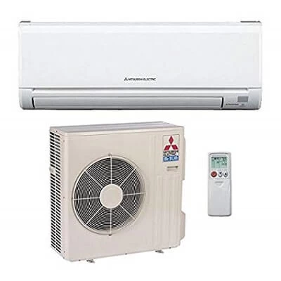
| Fault Codes | Problem |
|---|---|
| A0 | Duplicate address — Lossnay units attached with the same address — change addresses and reset the units power |
| A2 | Hardware error of transmission processor (Lossnay) — check comms wiring, and for possible Lossnay board fault |
| A3 | Line busy no data could be transmitted for 8 minutes — check A- M-Net connections (TB7 and TB3) |
| A6 | Communication error with communication processor — Lossnay address not transmitted — check M-Net voltage |
| A7 | No ACK signal — check A- M-Net wiring, range of transmission wiring exceeded or if faulty A- M-Net converter |
| A8 | M-Net no response — check A- M-Net wiring, range of transmission wiring exceeded, faulty A- M-Net converter or if incorrect wire used for M-Net connection |
| EA | Mis-wiring/loose inter-connecting cables. Noise interference |
| EB | Mis-wiring/loose interconnecting cables. Noise interference. Wrong cable size/spec |
| EC | Start-up time over. The unit has failed to initialise after power up. Noise interference. Wrong cable size/spec |
| ED | Serial communication error. Comms error between boards on outdoor unit caused by M-Net interface board incorrectly fitted |
| EF | Non-defined error code. Noise interference — power down outdoor unit for 30 seconds then switch back on |
| E0 | Remote controller communication error — check wiring, connections and comms voltage. Also check Master/Slave settings if multiple systems are connected |
| E1 | Remote controller issue — if grouped, check addressing. If twinned, check wired to master indoor only |
| E2 | Remote controller issue — if grouped, check addressing. If twinned, check wired to master indoor only |
| E3 | Remote controller issue — not transmitting — if grouped, check addressing. If twinned check wired to master indoor only |
| E4 | Remote controller issue — not receiving — if grouped, check addressing. If twinned, check wired to master indoor only |
| E5 | Remote controller issue — not receiving — if grouped, check addressing. If twinned, check wired to master indoor only |
| E6 | Indoor/outdoor communication error, mainly caused by outdoor unit being powered up before indoor unit. Drain pump being wired into S1 and S2 causes interference |
| E7 | Comms fault between I/C and O/C — check for condensate pump at I/C, reset power to O/C, check 12/24Vdc on S2 and S3 possible I/C board failure |
| E8 | Comms failure indoor to outdoor (S2/S3) — check pumps wired in, check indoor isolator and re-power in the correct sequence i.e. indoor then outdoor |
| E9 | Comms failure indoor to outdoor (S2/S3) — check pumps wired in, check indoor isolator and re-power in correct sequence i.e. indoor then outdoor |
| FA | 51CM connector open — check thermal relay for disconnection or contact failure. Possible defective board |
| F1 | Reverse phase detection — check power supply, try swapping 2 phases round. Possible defective board |
| F2 | L3 phase open — check power supply, also check for open circuit protection devices |
| F3 | 63L open — check low pressure switch for disconnection or contact failure. Possible defective board |
| F4 | 49C open — compressor inner thermostat for open circuit or contact failure |
| F5 | 63H open — check high pressure switch for disconnection or contact failure. Possible defective board |
| F7 | Phase detection circuit fault — faulty outdoor board |
| F8 | No input detected at outdoor unit — outdoor board defective |
| F9 | Two or more protection devices are open — check protection devices for disconnection or contact failure |
| P1 | Return air thermistor fault (TH1) — check if TH1 disconnected or open or close circuit |
| P2 | Liquid pipe thermistor fault (TH2) check if TH2 disconnected or open or close circuit |
| P4 | Drain sensor fault — DS open or close circuit |
| P5 | High condensate level — drain pump failure or blockage in the drain |
| P6 | Freezing/Overheating of indoor unit heat exchanger — mainly caused by reduced air flow through indoor coil. Dirty filters. Fan motor problem. Blockage |
| P8 | Abnormal pipe temperature — mainly caused by refrigerant leakage. Possibility that the thermistor mounted incorrectly |
| P9 | TH5 condenser/evaporator thermistor open/close circuit. Disconnected from the board |
| U1 | High pressure trip — outdoor fan failure, blocked coil, blockage in the system, blocked filters on indoor in heating etc |
| U2 | High discharge temperature — compressor over heating due to lack of refrigerant, faulty thermistor, high ambient running conditions. Can also be caused by 49C (comp inner thermostat or external Klixon ) tripping |
| U3 | Discharge thermistor fault |
| U4 | Outdoor thermistor fault |
| U5 | Inverter heat sink temperature too high (TH8) — check for lack of air flow around heat sink, no silicone paste, faulty thermistor (temperature can be read from service tool (or PAR21 on power inverter model)) |
| U6 | Compressor over current — carry out inverter output test and electrical checks to the compressor |
| U7 | Low discharge superheat — check TH4 reading is correct. Check LEV operations |
| ho | -For about 2 minustes following power-on, operation of the remote controller is not possible deu to system start-up. — Connector for the outdoor unit’s protection device is not connected. -Reserve or open phase wiring for the outdoor unit’s power terminal block (L1,L2,L3). -Incorrect wiring between indoor and outdoor units (incorrect polarity of S1,S2,S3). -Remote controller wire short. |
| FFFF | No unit. Buzzer sound: Triple beep. Operation Led: No lit. |
| U0-UP | Outdoor unit error. |
| F1-FA | Outdoor unit error. |
| E0-E5 | Signal error between remote controller and indoor units. |
| E6-EF | Communication error between indoor and outdoor units. |
| — | No alarm history. |
Mr Slim P Series (K)
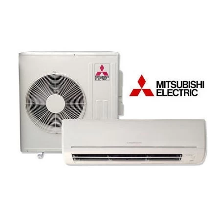
Mr. Slim P-Series is the ductless solution for demanding environments that require an efficient and reliable heating or cooling system. P-Series ductless systems are stylish, compact, and more attractive than traditional systems. Advanced technology also means your Mr. Slim ductless system will run more efficiently than a conventional unit, saving you from rising energy costs.
| Fault Codes | Problem |
|---|---|
| EO | System transmission error — check for possible comms fault between I/C and R/C, could also be incorrect group or master/slave settings (check CN40, SW2 and SW6) |
| P1 | TH1 fault — check return air thermistor (6.4K_ @ 20°C) |
| P2 | TH2 fault — check coil/pipe thermistor (6.4K_ @20°C) |
| P3 | System transmission error — check for possible comms fault between I/C and R/C, could also be incorrect group or master/slave settings (check CN40, SW2 and SW6) |
| P4 | Drain sensor fault — check drain sensor resistance, connection and continuity |
| P5 | Drain fault — unit has detected high condensate — check for blockage in drain or tray, pump failure or sensor fault |
| P6 | Frost protection in cooling/Overheat protection in heating — detected by indoor coil sensor — general causes are lack of air flow or refrigerant charge problem |
| P7 | System error — address setting fault — check CN40 SW2 and SW6. Potential board issue |
| P8 | Abnormal pipe/coil temperature — no temperature change at indoor unit after 9 minutes of operation. General causes are outdoor unit tripped, problem with refrigerant charge or lack of air flow at the indoor unit. TH2 faulty or not mounted correctly |
| LD1 | Reverse phase on mains supply — change phases around, check for potential board problem |
| LD2 | Component open circuit — check CH, 52C, 21S4, SV, 63H and 26C for open circuit or disconnected |
| LD3 | Outdoor coil thermister is open or short circuit may be disconnected or outdoor board fault |
| LD4 | 63H high pressure switch open — investigate high pressure causes, 63H switch disconnected |
| LD5 | 51CM overcurrent relay open — compressor locked or pulling too much current — check power supply |
| LD6 | 26C thermal switch open — check if refrigerant level low or if 26C is disconnected |
| LD7 | Overheat protection — coil temp has exceeded 67°C — reduced airflow through condenser — check for fan motor problem or thermistor problem |
| LD8 | Input circuit of outdoor board — replace the outdoor board |
Multi City VRF
The CITY MULTI S series (for small applications) and Y series (for large applications) make use of a two-pipe refrigerant system, which allows for system changeover from cooling to heating, ensuring that a constant indoor climate is maintained in all zones.
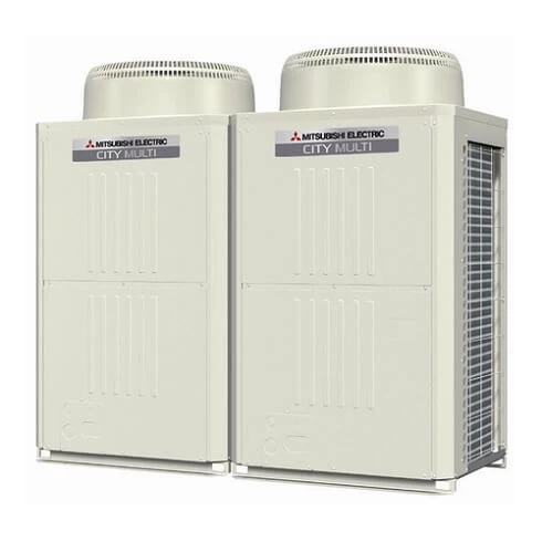
| Error Codes | Problem |
|---|---|
| 403 | Comms fault between boards — check inverter error detail for which 2 boards, check transformer, bus voltage and inter-connecting cables |
| 900 | Lossnay unit in test run |
| 1102 | High compressor discharge temperature. Discharge temperature has exceeded 110°C or more. Short of refrigerant. Discharge thermistor |
| 1111 | Low pressure/temperature fault — check thermistors (TH2, TH3, TH4), gas charge, indoor fan, heat exchanger and filter |
| 1112 | Low pressure/temperature fault — check thermistors (TH2, TH3, TH4), gas charge, indoor fan, heat exchanger and filter |
| 1113 | Low pressure/temperature fault — check thermistors (TH2, TH3, TH4), gas charge, indoor fan, heat exchanger and filter |
| 1202 | Preliminary fault to 1102 |
| 1204 | Preliminary heat exchanger gas temperature sensor fault — check thermistors 10a and 10b |
| 1205 | Preliminary thermistor fault (TH5) |
| 1211 | Preliminary thermistor fault (TH2) |
| 1214 | Preliminary thermistor fault (THHS) |
| 1216 | Preliminary thermistor fault (TH7) |
| 1217 | Preliminary thermistor fault (TH8) |
| 1219 | Preliminary thermistor fault (TH9) |
| 1221 | Preliminary thermistor fault (TH6) |
| 1243 | Preliminary thermistor fault (TH10) |
| 1301 | Low pressure fault (63L operation) low pressure sensor sensing less than 1 bar immediately before starting |
| 1302 | High pressure fault — check pressure in system for more than 29 bar (R407c) 38 bar (R410A). Check high pressure sensor against gauge pressure |
| 1368 | Pressure sensor fault (PS1) at BC — compare pressure reading on SW1 on O/C |
| 1370 | Pressure sensor fault (PS3) at BC — compare pressure reading on SW1 at O/C |
| 1402 | Preliminary fault to 1302 |
| 1500 | System overcharge. Abnormal low compressor superheat — discharge thermistor TH4 |
| 1501 | High compressor shell temp — check for shortage of gas, insufficient indoor index running (comms room units) |
| 1505 | Suction pressure abnormal — generated by low pressure sensor detecting a vacuum — check for blockage, closed valve or sensor fault |
| 2500 | Detecting lack of water flow on a water circuit |
| 2502 | I/C has water level in drip tray, when the unit was running in cooling (temperature sensors — check for open or closed circuit and operation of pump) |
| 2503 | I/C has water level in drip tray when the unit was running in cooling (float sensor — check for closed circuit on float switch and operation of pump) |
| 2600 | Water leak from humidifier |
| 4100 | Compressor over current protection on Mr Slim with M-net interface — check inverter or compressor |
| 4101 | Compressor over current protection on Mr Slim with M-net interface — check inverter or compressor |
| 4102 | Open phase fault — check power supply and noise filter for loss of phase, check wiring and fuses |
| 4103 | Reverse phase fault — check phase rotation, loss of phase through the noise filter, fuse blown and high pressure switch open at power on |
| 4106 | Transmission power supply fault — check wiring, high current, incorrect voltage on transmission line and/or M-Net board |
| 4108 | Over current protection on DOL compressor — check power supply, contactor and compressor |
| 4115 | Power supply abnormal — check power, fuses, connections and PCB |
| 4116 | Fan motor abnormal — check fan motor and board (relates to indoor unit or Lossnay unit) |
| 4124 | Thermal switch (49C) open circuit on Mr Slim on M-Net — reset and check pressures and air flow |
| 4210 | Compressor over current problem — check inverter balance. Compressor and inverter |
| 4220 | Low inverter board BUS voltage. Less than 289VdcDC is detected. — check mains supply |
| 4225 | Low DC voltage on Vdc on fan inverter — check CNVdc for 300Vdc on diode stack and check mains power supply to outdoor unit |
| 4230 | High temperature on heat sink on inverter — check for blockages in air duct, failure of INV fan or failure of thermistor |
| 4235 | Fan inverter heat sink overheat protection. Reduced airflow through heat sink. Fan motor problem. THHS thermistor problem |
| 4240 | Over current protection. If high current is detected for more than 10 minutes — check inverter balance. Reduced airflow through heat sink |
| 4245 | Over current protection. Possible ACCT current sensor fault. Should read 280 ohms between pins 1 & 2 and across pins 3 & 4 |
| 4250 | Over current protection. Inverter IPM problem. Compressor lock — check inverter balance |
| 4255 | Inverter cooling fan problem — if high static fan is used then check that SW3-9 is on |
| 4260 | Preliminary inverter heat sink overheat protection. Reduced airflow through heat sink. Fan motor problem. THHS thermistor problem |
| 5101 | Thermistor fault at indoor/outdoor unit — check fault code address |
| 5102 | Thermistor fault at indoor/outdoor unit — check fault code address |
| 5103 | Thermistor fault at indoor/outdoor unit — check fault code address |
| 5104 | Thermistor fault at indoor/outdoor unit — check fault code address (indoor fault — check SW7-3 is off) |
| 5105 | TH5 open/short circuit — check if the TH is disconnected from the board |
| 5106 | TH6 open/short circuit — check if the TH is disconnected from the board |
| 5107 | TH7 open/short circuit — check if the TH is disconnected from the board |
| 5108 | TH8 open/short circuit — check if the TH is disconnected from the board |
| 5109 | TH9 open/short circuit — check if the TH is disconnected from the board |
| 5110 | TH10 open/short circuit — check if the TH is disconnected from the board |
| 5111 | BC box thermistor error — TH11 open/short circuit, disconnected from board/pipe |
| 5112 | BC box thermistor error — TH10 open/short circuit, disconnected from board/pipe |
| 5113 | BC box thermistor error — TH open/short circuit, disconnected from board/pipe |
| 5114 | BC box thermistor error — TH open/short circuit, disconnected from board/pipe |
| 5115 | BC box thermistor error — TH15 open/short circuit, disconnected from board/pipe |
| 5116 | BC box thermistor error — TH16 open/short circuit, disconnected from board/pipe |
| 5201 | Pressure sensor fault outdoor unit/BC box — check fault code address/SW1 pressure sensor readings |
| 5202 | Pressure sensor fault (PS2) in the BC box |
| 5203 | Pressure sensor fault (PS3) in the BC box |
| 5300 | A-Control UH fault — see Mr Slim fault code list |
| 5301 | Current sensor fault, ACCT or DCCT — check inv. error details |
| 5401 | Temperature sensor fault — check CN30 for humidity sensor |
| 5701 | Loose float switch connector — check switch, check CN4F on indoor unit |
| 6201 | TB7 transmission line communication error — check for voltage abnormality/short |
| 6202 | Transmission processor hardware error — check for noise/short on M-Net cable |
| 6600 | Repeat address fault — two or more units are assigned the same address — correct the repeated address |
| 6601 | Polarity setting error — no voltage or short circuit on the m-net transmission line |
| 6602 | Hardware error of transmission processor. Noise interference. Polarity problem on TB7 |
| 6603 | Bus circuit busy — check if indoor unit, Lossnay unit or anything else has been wired into TB7, instead of TB3 |
| 6607 | Communication issue — no response back from unit whilst system is operational |
| 6608 | Communication error — loss of voltage or noise entering the transmission line |
| 6700 | K control communication error — R22 type unit connected onto M-Net circuit comms error |
| 6701 | K control communication error — R22 type unit connected onto M-Net circuit comms error |
| 6702 | K control duplicate address error — two or more R22 type units connected onto M-Net circuit with the same address |
| 6750 | K control communication error — R22 type unit connected onto M-Net circuit comms error |
| 6751 | R22 R/A thermistor fault (P1) |
| 6752 | R22 frost protection at I/C (P6) |
| 6753 | Comms fault between O/C and I/C |
| 6754 | R22 drain fault (P5) |
| 6755 | R22 drain fault (P5) |
| 6756 | R22 frost protection at I/C (P6) |
| 6757 | System error |
| 6758 | Comms fault between I/C and O/C |
| 6761 | R22 R/A thermistor fault (P1) |
| 6762 | R22 TH2 fault check resistance (P2) |
| 6763 | R22 Comms fault between I/C and O/C |
| 6764 | R22 drain fault (P4) |
| 6765 | R22 drain fault (P5) |
| 6766 | R22 frost protection at I/C (P6) |
| 6767 | R22 comms fault between I/C and O/C |
| 6771 | K abnormality — high pressure abnormality or low pressure abnormality |
| 6772 | K abnormality — inner thermostat function, discharge temperature abnormality, shell thermostat function, over current protection |
| 6773 | K abnormality — radiator plate thermostat function |
| 6774 | K abnormality — outdoor thermistor abnormality |
| 6775 | K abnormality — pressure sensor abnormality, indoor/outdoor communication error |
| 6776 | K abnormality — over current shut-off |
| 6777 | K abnormality — system error |
| 6778 | K abnormality — normal |
| 6779 | K abnormality — refrigerant overcharge, abnormal voltage, abnormal CT sensor |
| 6830 | Comms fault between I/C and R/C check connections to MA R/C and check for 12Vdc check R/C not set sub controller |
| 6831 | MA R/C communication fault — check connections on TB15 or that the controller was removed while the I/C was powered |
| 6832 | MA controller comms fault — check cable length no bigger than 500m, check connection and type of cable used, check R/C not set sub on field settings |
| 6833 | MA controller comms fault check cable length no bigger than 500m, check connection and type of cable used, check R/C not set sub on field settings |
| 6834 | MA Controller comms fault — check cable length no bigger than 500m, check connection and type of cable used, check R/C not set sub on field settings |
| 6840 | A-Control E6/E8 fault — see Mr Slim fault code list |
| 6841 | A-Control E7/E9 fault — see Mr Slim fault code list |
| 6844 | A-Control EA fault — see Mr Slim fault code list |
| 6845 | A-Control Eb fault — see Mr Slim fault code list |
| 6846 | A-Control EC fault — see Mr Slim fault code list |
| 7100 | Over capacity — (R2 150% index exceeded) (Y 130% index exceeded) |
| 7101 | Capacity setting error — SW2 set wrong on indoors, SW5 on YHMA outdoor, (SW3-10 on older kit) |
| 7102 | Error in number of connected units — loss of M-Net voltage (short or break), no power to BC, wrong SW5 setting on box, wrong box type |
| 7105 | Address setting error — OC or BC addressed wrong |
| 7106 | Attribute setting error — SW3-1 setting on a GUF |
| 7107 | Port setting error — check if too much capacity on a single port, wiring SW2 setting, wrong SW14 setting or wrong units on a box when using multiple boxes |
| 7110 | Check SW5-7 is correctly set |
| 7111 | Remote control sensor fault — SW1 — 1 on and no controllers fitted or faulty remote controller |
| 7113 | Function setting error — wrong SW5 setting or wrong resistors fitted on YHM-A |
| 7117 | Model setting error — SW5 set wrong or wrong resistors in |
| 7130 | Incompatible equipment on M-Net — check split with MAC 399 wired onto the TB5 line TB5 line, not the TB7 |
Cassette AC

| Alarm Codes | Solutions |
|---|---|
| P1 | Intake sensor error |
| P2 | Pipe (TH2) sensor error |
| P9 | Pipe (TH5) sensor error |
| E6,E7 | Indoor/outdoor unit communication error |
| P4 | Drain sensor error/Float switch connector (CN4F) open |
| P5 | Drain pump error |
| PA | Forced compressor stop (due to water leakage abnormality) |
| P6 | Freezing/Overheating protection operation |
| EE | Communication error between indoor and outdoor units |
| P8 | Pipe temperature error |
| E4,E5 | Remote controller signal receiving error |
| Fb | Indoor unit control system error (memory error, etc.) |
| PL | Refrigerant circuit abnormal |
| E0,E3 | Remote controller transmission error |
| E1,E2 | Remote controller control board error |
| E9 | Indoor/outdoor unit communication error (Transmitting error) (Outdoor unit) |
| UP | Compressor overcurrent interruption |
| U3,U4 | Open/short of outdoor unit thermistors |
| UF | Compressor overcurrent interruption (When compressor locked) |
| U2 | Abnormal high discharging temperature/49C operated/ insufficient refrigerant |
| U1,Ud | Abnormal high pressure (63H operated)/Overheating protection operation |
| U5 | Abnormal temperature of heat sink |
| U8 | Outdoor unit fan protection stop |
| U6 | Compressor overcurrent interruption/Abnormal of power module |
| U7 | Abnormality of super heat due to low discharge temperature |
| U9,UH | Abnormality such as overvoltage or voltage shortage and abnormal synchronous signal to main circuit/Current sensor error |
Ecodan
Ecodan air source heat pumps use 1kW of electrical energy input and take 2.2kW of low temperature renewable heat energy from the air, producing a high efficient 3.2kW heat energy output. This heats refrigerant in the system which in turn heats water for domestic hot water and space heating.

| Fault Codes | Problem |
|---|---|
| F3 | Low pressure switch failure — check connection on the board and continuity of switch |
| F5 | High pressure switch failure — check connection onto board and continuity of switch |
| F9 | Both pressure switch contacts are open at the same time — check connection onto board and continuity of switch and for a potential board failure |
| EA | Mis-wiring fault between FTC and Ecodan — check S1,S2,S3 also check voltages and comms |
| EB | Mis-wiring fault between FTC and Ecodan — Check S1,S2,S3 also check voltages and comms |
| EC | Unit cannot finish start up process — generally caused by a comms fault |
| U1 | Ecodan high pressure fault — mainly caused by incorrect water flow rates — check with flow setter |
| U2 | Ecodan high compressor discharge temperature — mainly caused by refrigerant shortage or dirty condenser |
| U3 | Ecodan discharge thermistor problem — mainly caused by TH4 discharge thermistor — open/close circuit |
| U4 | Open or close circuit Ecodan thermistors (TH3, TH32, TH33, TH6, TH7, TH8) — open or close circuit or disconnected from main board |
| U5 | Inverter heat sink overheat protection (W50 and W85 models 77°C, HW140 model 95°C — reduced air flow through Ecodan — faulty fan motor |
| U6 | Inverter/Compressor over current — system indicates possible IPM error |
| U8 | Ecodan fan motor problem — mainly caused by DC fan motor being disconnected, connected or obstructed with the power on or possible main board fault |
| U9 | Over voltage or under voltage — mainly caused by either CN2 or CN5 loose or disconnected or decrease of mains power supply |
| UD | Overheat protection TH3 ≥ 70°C or 63HS ≥ 70°C saturation temperature |
| UF | Compressor over current/Compressor lock — occurs within 30 seconds of compressor start |
| UH | Abnormal running current — < 1A or > 40A detected during operation — check CN5 connections |
| UL | Open circuit (63L ) |
| UP | Over current detected after 30 seconds of operation — do an inverter test to determine outputs balanced |
| E0 | Transmitting Error PAR W21 — check refrigerant address on SW1 of Ecodan |
| E1 | Faulty controller |
| E3 | Transmitting Error (PAR W21) — check refrigerant address on SW1 of Ecodan |
| E4 | Receiving Error (PAR W21) — check refrigerant address of SW1 on Ecodan |
| E5 | Receiving Error (PAR W21) — check refrigerant address of SW1 on Ecodan |
| E6 | Indoor/Outdoor communication error — mainly due to Ecodan being powered up before FTC(2) |
| E8 | Indoor/Outdoor communication error — mainly due to Ecodan being powered up before FTC(2) |
| E9 | Indoor/Outdoor communication error — mainly due to Ecodan being powered up before FTC(2) |
| EF | Non-defined error code — noise interference — power down Ecodan for 30 seconds then switch back on |
| ED | Serial communication fault between Ecodan main board and Ecodan inverter board — mainly due to loose CN2 or CN5 cable |
| P1 | Flow temp sensor fault — TH1 not connected, short or open circuit |
| P6 | Over heating at heat exchanger — lack of water flow, air in the system, flow rate incorrectly set, blockage or pump problem |
| P8 | No temp change at plate heat exchanger — problem with flow rate (too high) — incorrect sizing of system |
| P9 | TH5 Fault — TH5 not connected, short or open circuit, FTC not configured for heating only |
| PE | Inlet water temp fault — TH32 is below 10°C whilst compressor is in operation — possible thermistor out of range, short of gas, incorrect sizing of radiator or problem in the water circuit (blockage, pump failure etc) |
Hot Water Heat Pumps PWFY Series
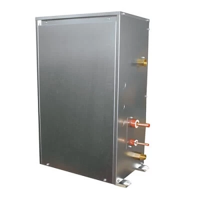
12.5kW Hot Water Module. Flexibility to create very large systems. Can be installed in conjunction with City Multi VRF air conditioning. Available in one size: PWFY-P100VM-E-BU (12.5kW heating) which is modular to allow creation of larger solutions. Sanitary water heating has suitable applications in: hotels and motels, apartments, commercial kitchens and laundries, office buildings, food processing industry, heat recovery from air conditioning systems into sanitary water storage, and direct sanitary water heating is also possible.
| Fault Codes | Problem |
|---|---|
| 403 | Comms fault between boards — check between control board an inverter board |
| 403 | Comms fault between boards — check between control board an fan board |
| 1102 | High compressor discharge temperature — discharge temp has exceeded 115°C or more — check if short of refrigerant or discharge thermistor |
| 1301 | Low pressure fault — low pressure sensor sensing less than 1 bar immediately before starting |
| 1302 | High pressure fault — check system pressure exceded 32.3 bar, check high pressure sensor (63HS) against gauge pressure |
| 2000 | Pump interlock error — pump interlock open whilst system in operation |
| 2134 | Abnormal water temperature (TH6) has exceded 85°C |
| 2135 | Water source heat exchanger frozen (TH6) or (TH8) reading 2°C |
| 4102 | Open phase fault — check power supply and noise filter for loss of phase, check wiring and fuses |
| 4115 | Power supply abnormal — check power, fuses, connections and PCB |
| 4220 | Low inverter board BUS voltage — less than 200Vdc is detected during in inverter operation — check mains supply |
| 4220 | Bus voltage error PAM damage — replace the inverter board |
| 4220 | High bus voltage Vdc>380v — check power supply and possible faulty inverter board |
| 4220 | Replace inverter board |
| 4230 | High temperature (85°C) on heat sink on inverter — check for blockages in air duct, failure of INV fan failure of INV fan or failure of thermistor (THHS) |
| 4250 | Over current protection — inverter IPM problem or compressor lock — check inverter balance |
| 4250 | ACCT sensor over current detection 34.5A peak or 16A rms is detected — check the compressor for failure, or possible inverter board failure |
| 5102 | Thermistor TH22 failure |
| 5103 | Thermistor TH13 or TH23 failure |
| 5104 | Thermistor TH11 failure |
| 5106 | Thermistor TH6 failure |
| 5108 | Thermistor TH8 failure |
| 5110 | Thermistor THHS failure |
| 5201 | High pressure sensor fault — check the system pressure is >1 bar, check the operation of 63HS high pressure transducer |
| 5202 | Pressure sensor fault |
| 5301 | Current sensor fault, ACCT or DCCT — check inv. error details |
| 5301 | Low output current <1.5A rms whilst the inverter is in operation |
Packaged Hot Water Heat Pump CAHV
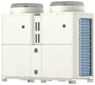
45kW Packaged Hot Water Heat Pump. Can be combined to max. 70kW. “Flash-injection Circuit”, which is designed for our ZUBADAN CITY MULTI (air conditioning system for cold regions), is mounted in our new Hot Water Heat Pump. By utilizing our advanced “Flash-injection Circuit” and the latest high-efficiency compressor, Hot Water Heat Pump provides hot water upto 70°C, and produces less capacity drop at low outdoor temperature.
| Error Codes | Problem |
|---|---|
| AFSA | Water supply cut-off (flow switch has been triggered) — check flow switch and wiring |
| AHP1 | High pressure fault — check water flow, possible high pressure sensor fault LEV fault |
| AdSH | Compressor crank case temperature of 10°C or less for 40 minutes while compressor in operation — check for possible failure of fan motor, low pressure sensor, compressor shell thermistor, high pressure sensor, discharge thermistor (TH1 TH5), LEV or SV2 |
| 1303 | Low pressure protection low pressure below 6 bar within 30 sec of start up — possible failure of LP sensor, air inlet thermistor fault (TH4 TH8), suction temperature (TH2 TH6), LEV bypass check valve |
| 1103 | Compressor shell bottom temperature exceeded 80°C detected whilst compressor running |
| 5109 | Compressor shell thermistor faulty (TH3 TH6), LEV failure |
| 5110 | Outside temperature thermistor fault — check TH9 |
| 5112 | Water inlet temperature — check TH10 main circuit |
| 5111 | Water inlet temperature — check TH12 sub circuit |
| 5113 | Outlet water temperature — check TH11 main circuit |
| 5103 | Outlet water temperature — check TH12 sub circuit |
| 5107 | Compressor shell temperature — check TH3 main circuit |
| 5101 | Compressor shell temperature — check TH7 sub circuit |
| 5105 | Discharge temperature — check TH1 main circuit |
| 5102 | Discharge temperature — check TH5 sub circuit |
| 5106 | Inlet temperature — check TH2 main circuit |
| 5104 | Inlet temperature — check TH6 sub circuit |
| 5108 | Air to refrigerant heat exchanger inlet temperature — check TH4 main circuit |
| 5114 | Air to refrigerant heat exchanger inlet temperature — check TH8 sub circuit |
| 5115 | Common return water when using multiple outdoors — check TH14 |
| 5117 | Common return water when using multiple outdoors — check TH15 |
| 5118 | High pressure sensor or high pressure fault — check 63HS sensor or 63H (hp switch) |
| 7113 | Low pressure sensor low or low pressure fault — check 63LS |
| 7117 | Model setting error 1 — mis-set switch |
| 4115 | Model setting error 2 — faulty Z21 resistor |
| A471 | Power supply frequency fault — power supply frequency is not 50Hz or 60Hz |
| 1104 | Discharge temperature fault — 120°C detected during compressor operation — check water flow, pump, high pressure sensor fault or LEV fault |
| AC61 | Power supply fault — check transmission power supply or if PCB faulty |
MR Slim Operation Light Blinking
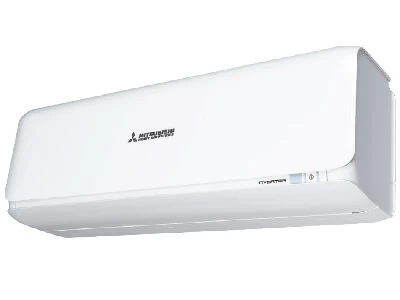
Flashing of POWER lamp indicates abnormalities. Before taking measures, make sure that the symptom reappears for accurate troubleshooting. Self check table
When the indoor unit has started operation and the above detection method has detected an abnormality (the first detection after the power ON), the indoor electronic control P.C. board turns OFF the indoor fan motor with OPERATION INDICATOR lamp flashing.
| Indicator lamp | Solution |
|---|---|
| POWER lamp flashes. 0.5-second ON | Mis-Wiring or serial signal. Outdoor unit does not operate. When the serial signal form the outdoor unit is not received for a maximum of 6 minutes. |
| POWER lamp lights up | Out door control system. Outdoor unit does not operate. When it cannot properly read data in the nonvolatile memory of the inverter P.C. board or the outdoor electronic control P.C. board. Check the blinking pattern of the LED on the inverter P.C. board or the outdoor lectronic control P.C. board. |
| POWER lamp flashes. 2-time flash | Indoor coil thermistor. Room temperature thermistor. Indoor unit and outdoor unit do not operate. When the indoor coil or the room temperature thermistor is short or open circuit. |
| POWER lamp flashes. 3-time flash | Indoor fan motor. Indoor unit and outdoor unit do not operate. When the rotational frequency feedback signal is not emit during the indoor fan operation. |
| POWER lamp flashes. 5-time flash | Out door power system. Indoor unit and outdoor unit do not operate. When it consecutively occurs 3 times that the compressor stops for overcurrent protection or start-up failure protection witth in 1 minute after start-up. |
| POWER lamp flashes. 6-time flash | Outdoor thermistors. Indoor unit and outdoor unit do not operate. When the outdoor thermistors short or open circuit during the compressor operation. |
| POWER lamp flashes. 7-time flash | Out door control system. Indoor unit and outdoor unit do not operate. When it cannot properly read data in the nonvolatile memory of the inverter P.C. board or the outdoor electronic control P.C. board. |
| POWER lamp flashes. 14-time flash | Other abnonmality. Indoor unit and outdoor unit do not operate. An abnormality other than above mentioned is deteced. Confirm the abnormarity in detail using the failure mode recall function. |
Split AC Timer Light Blinking
| Trouble | Contents |
|---|---|
| 3 blinking-1 blinking | Abnormality of comp. surface thermistor (TH32) and discharging temperature (TH4) |
| 3 blinking-2 blinking | Abnormal high pressure (High pressure switch 63H operated.) |
| 3 blinking-3 blinking | Abnormality of outdoor fan motor rotational speed. Protection from overheat operation(TH3). |
| 3 blinking-4 blinking | Compressor overcurrent breaking (Start-up locked). Compressor overcurrent breaking. Abnormality of current sensor (P.B.). Abnormality of power module. |
| 3 blinking-5 blinking | Open/short of discharge thermistor (TH4) and comp. surface thermistor (TH32). Open/short of outdoor thermistors (TH3, TH6, TH7 and TH8). |
| 3 blinking-6 blinking | Abnormality of heatsink temperature |
| 3 blinking-7 blinking | Abnormality of voltage |
| 4 blinking-1 blinking | Abnormality of room temperature thermistor (TH1). Abnormality of pipe temperature thermistor /Liquid (TH2). Abnormality of pipe temperature thermistor/Condenser-Evaporator. |
| 4 blinking-2 blinking | Abnormality of drain sensor (DS) Float switch(FS) connector open. Indoor drain overflow protection. |
| 4 blinking-3 blinking | Freezing (cooling)/overheating (heating) protection |
| 4 blinking-4 blinking | Abnormality of pipe temperature |
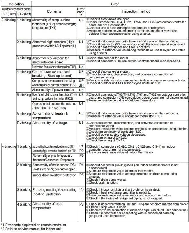
Aircon RedLINK Codes
| Error Codes | Meaning |
|---|---|
| E0 27 | Verify device temperature is within operating range. If within range for at least 30 minutes and problem persists, replace Remote Controller. |
| E0 91 | Communication was established between wireless receiver and the indoor unit, but communication has been lost for 10 minutes. Check cable connection. Try replacing the cable. |
| E1 29 | Attempting to connect incompatible wireless devices. |
| E1 34 | Low signal strength. Move wireless device to a different location and try again. |
| E1 38 | Make sure Connect light on wireless receiver is flashing and you are 2+ feet away from wireless receiver. |
| E1 54 | Indoor unit does not support wireless receiver. |
Troubleshooting
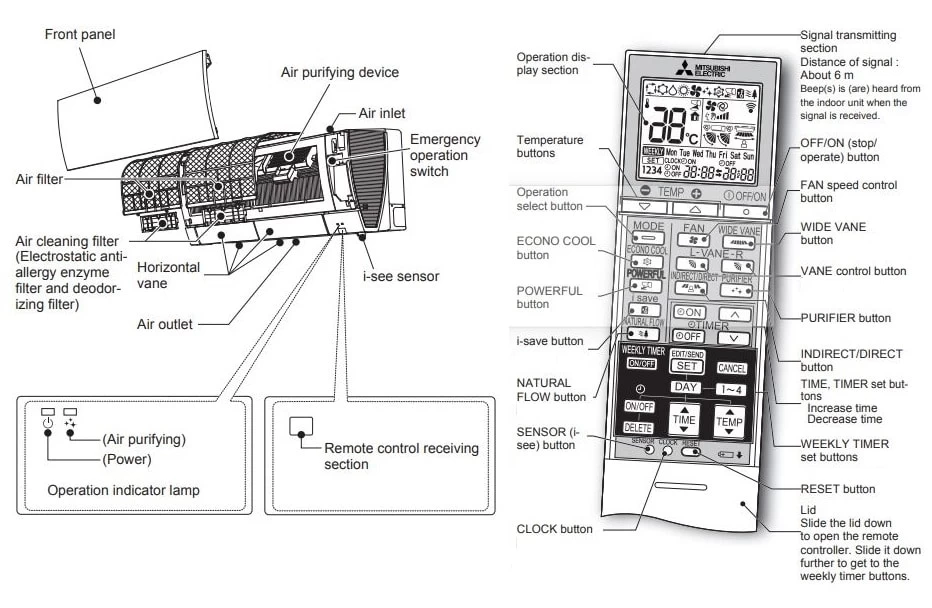
Even if these items are checked, when the unit does not recover from the trouble, stop using the air conditioner and consult your dealer.
Symptom: The unit cannot be operated.
Explanation & Check points:
- Is the breaker turned on?
- Is the power supply plug connected?
- Is the ON timer set?
Symptom: The horizontal vane does not move.
Explanation & Check points:
- Are the horizontal vane and the vertical vane installed correctly?
- Is the fan guard deformed?
- When the breaker is turned on, the horizontal vanes’ position will be reset in about a minute. After the reset has completed, the normal horizontal vanes’ operation resumes. The same is true in the emergency cooling operation.
Symptom: The airfl ow direction changes during operation. The direction of the horizontal vane cannot be adjusted with the remote controller.
Explanation & Check points:
- When the unit is operated in COOL or DRY mode, if the operation continues with air blowing down for 0.5 to 1 hour, the direction of the airfl ow is automatically set to horizontal position to prevent water from condensing and dripping.
- In the heating operation, if the airfl ow temperature is too low or when defrosting is being done, the horizontal vane is automatically set to horizontal position.
Symptom: Water leaks from the outdoor unit.
Explanation & Check points:
- During COOL and DRY operations, pipe or pipe connecting sections are cooled and this causes water to condense.
- In the heating operation, water condensed on the heat exchanger drips down.
- In the heating operation, the defrosting operation makes ice forming on the outdoor unit melt and drip down.
Symptom: The display on the remote controller does not appear or it is dim. The indoor unit does not respond to the remote control signal.
Explanation & Check points:
- Are the batteries exhausted?
- Is the polarity (+, -) of the batteries correct?
- Are any buttons on the remote controller of other electric appliances being pressed?
Symptom: The room cannot be cooled or heated sufficiently.
Explanation & Check points:
- Is the temperature setting appropriate?
- Is the fan setting appropriate? Please change fan speed to High or Super High.
- Are the fi lters clean?
- Is the fan or heat exchanger of the indoor unit clean?
- Are there any obstacles blocking the air inlet or outlet of the indoor or outdoor unit?
- Is a window or door open?
- It may take a certain time to reach the setting temperature or may not reach that dependingon the size of the room, the ambient temperature, and the like.
Symptom: The air from the indoor unit smells strange.
Explanation & Check points:
- Are the fi lters clean?
- Is the fan or heat exchanger of the indoor unit clean?
- The unit may suck in an odor adhering to the wall, carpet, furniture, cloth, etc. and blow it out with the air.
Symptom: Weekly timer does not operate according to settings.
Explanation & Check points:
- Is the ON/OFF timer set?
- Transmit the setting information of the weekly timer to the indoor unit again. When the information is successfully received, a long beep will sound from the indoor unit. If information fails to be received, 3 short beeps will be heard. Ensure information is successfully received.
- When a power failure occurs and the main power turns off, the indoor unit built-in clock will be incorrect. As a result, the weekly timer may not work normally.
Electrical Wiring Diagram

Refrigerator Diagram
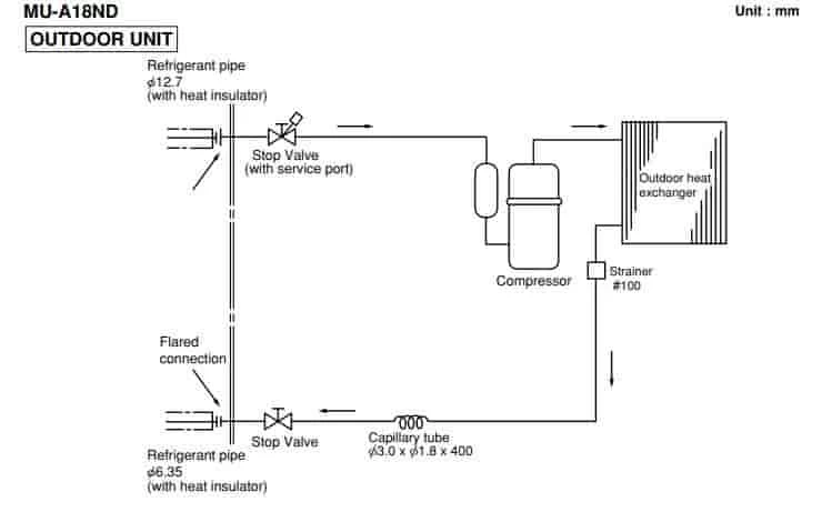
Manuals PDF
Mitsubishi Air Conditioning Service Handbook PDF
Mitsubishi Air Conditioning Service Manual PDF
Mitsubishi Electric MRCH1 Remote ControllerOperating Manual PDF
Mitsubishi Electric Split AC Manual MSZ-AP22VGD PDF
Mhk1 Wireless Remote Receiver Kit Manual PDF
MIFH1, MRCH1, MCCH1, MOS1 Controller Kit Installation Manual PDF
Mitsubishi Air Conditioning Error Codes PDF – R410A Systems
- Author
- Recent Posts

Regarding error and fault codes, we believe sharing knowledge is the best way to help everyone. That is why we established ACErrorCode.com, to give you every bit of info you need as a customer. HVAC Expert Contact: dannyreese@acerrorcode.com
![]()
*If you can’t find the code you’re looking for on our site, please let us know, and we’ll update our database as soon as possible.