
Air Handling seq. — user manual
14.1| Actions following an alarm
When an alarm occurs, the following actions generally ensue (according to what defined through the Configurator
software «AHU_Interface_vNN.xls»).
»
»
»
14.2| Types of reset
Through the Configurator it is possible to set how the alarms are to be reset: manually, automatically or
semi-automatically.
»
»
»
The buzzer is silenced the first time any button is pressed, even if the alarm condition remains in effect; it will remain
silent until a new alarm occurs.
14.3| Alarms table
Each alarm is characterized by:
»
»
»
»
»
»
»
»
»
as described in the table below.
The columns in grey contain data that can be modified with the Configurator software
ALARMS TABLE
Code
Description
A01
Supply fan
alarm
A02
External
damper locked
56
The buzzer sounds, if present and if envisaged by the specific alarm
The alarm relay «ALA — Alarm» or the warning «WAR — Warning» is activated depending on what is envisaged
by the specific alarm
(see «14.3] Alarms
The Configurator can be used to define whether the alarm is activated when the unit is OFF.
In the absence of a alarm condition, the Normally Closed (N.C.) and Normally Open
(N.O.) state of the alarm relay is defined when the physical output is configured. If the
polarity is «N.O. » (default setting), the relay is powered in case of an alarm.
The alarm icon is displayed along with the code for the alarm and its description (only for units with LCD
display). For a complete description of the user interface in the case of alarms,
If reset is manual, a specific procedure is required to resetting them if the alarm
condition doesn’t exists any more: from the menu (Menu: ALA – Alarms, Sub-menu: RAL
– Reset Alarms) to reset all Alarms present or by pressing ENTER from within the alarms
display screen to reset only the currently displayed alarm
If reset is automatic, the alarm is deactivated and the signal
disappears as soon as the alarm conditions cease.
If reset is semi-automatic, it means that reset reverts from automatic to manual
after it has occurred a certain (configurable) number of times.
code: ID tag that unequivocally identifies the alarm and which is displayed on the screen;
description: displayed only on LCD displays;
source of the alarm;
type of reset: (-1=automatic, 0=manual, >0=number of occurrences for semi-automatic alarms);;
if semi-automatic alarms, the period for counting alarm occurrences; if during this time the
alarm exceeds its maximum number of occurrences, it becomes a manual reset alarm;
delays for detecting the alarm after start-up and when in steady operation;
whether it is active even when the machine is in standby mode;
how it affects the alarm relay, warning and buzzer;
how it affects the unit actuators
Source
Type of
reset
Digital input
-1
«SupFan Alarm»
(automatic)
Digital input
-1
«ExtDamp
(automatic)
Closed» and
output «External
Damper» active
DKRCC.PS.RI.A1.02 / 520H4358 — Air Handling Seq. user manual — V 2.2
Produced by Danfoss Electronics spa Graphic Department, 10-2009
table»).
(see «2] User
Semi
Delay
Operating
automatic
at
delay
period
start-
(min)
up
0
0
0
0
0
3
Danfoss Electronics spa
(see «14.3] Alarms
table»).
(see «2] User
interface»).
interface»).
Active
Alarm
Warning
Buzzer
with
relay
relay
unit
OFF
NO
YES
YES
YES
NO
YES
YES
YES
Actuators
OFF
Supply fan
Supply fan
-
Contents
-
Table of Contents
-
Bookmarks
Quick Links
MAKING MODERN LIVING POSSIBLE
Air handling Seq.
control algorithm
Software version 2.1
REFRIGERATION &
AIR CONDITIONING DIVISION
Danfoss Electronics spa
User manual
Related Manuals for Danfoss MCX08M
Summary of Contents for Danfoss MCX08M
-
Page 1
MAKING MODERN LIVING POSSIBLE Danfoss Electronics spa Air handling Seq. control algorithm Software version 2.1 User manual REFRIGERATION & AIR CONDITIONING DIVISION… -
Page 2: Table Of Contents
12.4| Fans lock Air quality control Alarms 14.1| Actions following an alarm 14.2| Types of reset 14.3| Alarms table Parameters DKRCC.PS.RI.A1.02 / 520H4358 — Air Handling Seq. user manual — V 2.2 Produced by Danfoss Electronics spa Graphic Department, 10-2009…
-
Page 3
17.1| Guide to modifying the application software 17.2| “Parameters” Page 17.3| “Alarms” Page 17.4| “Parameters_x_Model” Page 17.5| I/O configuration pages DKRCC.PS.RI.A1.02 / 520H4358 — Air Handling Seq. user manual — V 2.2 Produced by Danfoss Electronics spa Graphic Department, 10-2009… -
Page 4: Introduction
MMIMYK accessory, select the configuration to download onto the MCX on a case-by-case basis. DKRCC.PS.RI.A1.02 / 520H4358 — Air Handling Seq. user manual — V 2.2 Produced by Danfoss Electronics spa Graphic Department, 10-2009…
-
Page 5: User Interface
Passing from OFF to ON turns on the main screen. Activating of the digital and analog outputs is delayed, respectively, by the dOt and AOt times DKRCC.PS.RI.A1.02 / 520H4358 — Air Handling Seq. user manual — V 2.2 Produced by Danfoss Electronics spa Graphic Department, 10-2009…
-
Page 6: Main Screen
The main screen varies depending on whether a LED or LCD display is being used. 2.3.1| LED Display Fig 1_[User interface — LED display] DKRCC.PS.RI.A1.02 / 520H4358 — Air Handling Seq. user manual — V 2.2 Produced by Danfoss Electronics spa Graphic Department, 10-2009…
-
Page 7: Lcd Display
A” and “display B” for the version with LED display); » the symbols of the main active functions (see figure). Fig 2 _ [User interface — LCD display] DKRCC.PS.RI.A1.02 / 520H4358 — Air Handling Seq. user manual — V 2.2 Produced by Danfoss Electronics spa Graphic Department, 10-2009…
-
Page 8: Menu-Based Navigation
Unlock fans Winter Sets the winter operating mode Summer Sets the summer operating mode Tab 3 _ [User interface -Menu-based navigation] DKRCC.PS.RI.A1.02 / 520H4358 — Air Handling Seq. user manual — V 2.2 Produced by Danfoss Electronics spa Graphic Department, 10-2009…
-
Page 9: Displaying And Managing Alarms
The level for a given menu and the parameters is defined through the Configurator software. “ AHU_Interface_vNN.xls”. DKRCC.PS.RI.A1.02 / 520H4358 — Air Handling Seq. user manual — V 2.2 Produced by Danfoss Electronics spa Graphic Department, 10-2009…
-
Page 10: Parameters
If enabled through the Configurator software, makes it possible to access the input/output configuration screens. For each input/output for the instrument, it is possible to set the type, work field, polarity and function performed. DKRCC.PS.RI.A1.02 / 520H4358 — Air Handling Seq. user manual — V 2.2 Produced by Danfoss Electronics spa Graphic Department, 10-2009…
-
Page 11: Utilities
Unlock fans Sub-menu: WIN – Winter Sets the winter operating mode. Sub-menu: SUM – Summer Sets the summer operating mode. DKRCC.PS.RI.A1.02 / 520H4358 — Air Handling Seq. user manual — V 2.2 Produced by Danfoss Electronics spa Graphic Department, 10-2009…
-
Page 12
Heat seq. 2 power Humidification power Cool seq. 1 power Recovery (Mixing) power Tab 5 _ [Menu-based navigation — Screen description] DKRCC.PS.RI.A1.02 / 520H4358 — Air Handling Seq. user manual — V 2.2 Produced by Danfoss Electronics spa Graphic Department, 10-2009… -
Page 13: Configuring The Ahu Software
Define the control type, the control probe and if necessary the PID control parameters. (See “12] Supply and return fans”). DKRCC.PS.RI.A1.02 / 520H4358 — Air Handling Seq. user manual — V 2.2 Produced by Danfoss Electronics spa Graphic Department, 10-2009…
-
Page 14: Input/Output Configuration
Lock Fan Lock/Unlock fans Comf/Eco Comfort/Economy selection FreeHeatCool Freeheat/Freecool changeover Tab 7 _ [Configuring the AHU software — Digital Inputs] DKRCC.PS.RI.A1.02 / 520H4358 — Air Handling Seq. user manual — V 2.2 Produced by Danfoss Electronics spa Graphic Department, 10-2009…
-
Page 15
Controls the ON/OFF valve of coil 3 Valve3Open Controls opening of 3-point valve of coil 3 Valve3Close Controls closing of 3-point valve of coil 3 DKRCC.PS.RI.A1.02 / 520H4358 — Air Handling Seq. user manual — V 2.2 Produced by Danfoss Electronics spa Graphic Department, 10-2009… -
Page 16
Defrost Defrost activation HeatRequest Request of heating CoolRequest Request of cooling Tab 9_ [Configuring the AHU software — Digital Outputs] DKRCC.PS.RI.A1.02 / 520H4358 — Air Handling Seq. user manual — V 2.2 Produced by Danfoss Electronics spa Graphic Department, 10-2009… -
Page 17: Coils Control
As described in detail in “6.2| Heat and cool control sequences”, coils are controlled with heating and cooling control sequences according to the following figure. Fig 5 _ [Coils control — Heat and cool sequeces for coil] DKRCC.PS.RI.A1.02 / 520H4358 — Air Handling Seq. user manual — V 2.2 Produced by Danfoss Electronics spa Graphic Department, 10-2009…
-
Page 18: Coil Output Management
(e.g. electric resistances). In this case there are 3 possible way of control: linear step switch, variable step switch binary step switch. DKRCC.PS.RI.A1.02 / 520H4358 — Air Handling Seq. user manual — V 2.2 Produced by Danfoss Electronics spa Graphic Department, 10-2009…
-
Page 19: Valve Control
4.3.1| ON/OFF and 0/10V valve control Fig 7 _ [Coils control — ON/OFF and 0/10V valve control] DKRCC.PS.RI.A1.02 / 520H4358 — Air Handling Seq. user manual — V 2.2 Produced by Danfoss Electronics spa Graphic Department, 10-2009…
-
Page 20: Point Valve Control
4% position will cause the valve to fully close and a request for 96% will cause it to open all the way. DKRCC.PS.RI.A1.02 / 520H4358 — Air Handling Seq. user manual — V 2.2 Produced by Danfoss Electronics spa Graphic Department, 10-2009…
-
Page 21: Step Control
Linear step control is described in the following figure in case of 2 steps. Up to 3 steps are managed. Fig 8 _ [Coils control — Linear step control] DKRCC.PS.RI.A1.02 / 520H4358 — Air Handling Seq. user manual — V 2.2 Produced by Danfoss Electronics spa Graphic Department, 10-2009…
-
Page 22: Variable Step Switch
1000 17,0 Step 3 ON 1000 50,0 Step 3 OFF 1000 33,0 Tab 15_ [Coils control — Variable step switch] DKRCC.PS.RI.A1.02 / 520H4358 — Air Handling Seq. user manual — V 2.2 Produced by Danfoss Electronics spa Graphic Department, 10-2009…
-
Page 23: Binary Step Switch
Binary Step control is described in the following figure in case of 2 steps. Up to 3 steps are managed. Fig 10 _ [Coils control — Bianry step control] DKRCC.PS.RI.A1.02 / 520H4358 — Air Handling Seq. user manual — V 2.2 Produced by Danfoss Electronics spa Graphic Department, 10-2009…
-
Page 24: Locking Sequences
Heating lock -40,0 100,0 90,0 °C Tab 17_ [Coils control — Locking sequences] Fig 11 _ [Coils control — Locking sequences] DKRCC.PS.RI.A1.02 / 520H4358 — Air Handling Seq. user manual — V 2.2 Produced by Danfoss Electronics spa Graphic Department, 10-2009…
-
Page 25: Pumps Control
The “ice” blinking icon signals this function. Fig 12 _ [Coils control — Pumps winter start] (See “9] Frost protection” for further actions to prevent frost.) DKRCC.PS.RI.A1.02 / 520H4358 — Air Handling Seq. user manual — V 2.2 Produced by Danfoss Electronics spa Graphic Department, 10-2009…
-
Page 26: Single Heat/Cool Coils
Fig 13 _ [Coils control — Comparison between probe HC1 and Setpoint HC2] *Summer/Winter selection has influence over the way of controlling fans. (See “12.1 Type of supply and return fans”). DKRCC.PS.RI.A1.02 / 520H4358 — Air Handling Seq. user manual — V 2.2 Produced by Danfoss Electronics spa Graphic Department, 10-2009…
-
Page 27: Cooling Coil Defrost Control
“HRE – HeatRequest” is ON when the load demand from Heat Sequence 1 or 2 is greater than 0. “HCE – CoolRequest” is ON when the load demand from Cool Sequence 1 is greater than 0. DKRCC.PS.RI.A1.02 / 520H4358 — Air Handling Seq. user manual — V 2.2 Produced by Danfoss Electronics spa Graphic Department, 10-2009…
-
Page 28: Dampers And Energy Recovery Control
External Damper Mixing Damper 0/10V analog output External Damper Tab 23_ [Dampers and Energy recovery control — External and Mixing dampers] DKRCC.PS.RI.A1.02 / 520H4358 — Air Handling Seq. user manual — V 2.2 Produced by Danfoss Electronics spa Graphic Department, 10-2009…
-
Page 29: On/Off Dampers
“CSE — ExtDamp Closed” and “CSR — MixDamp Closed signals that the damper is closed and, at the same time, the damper control is active for at least 3 seconds. DKRCC.PS.RI.A1.02 / 520H4358 — Air Handling Seq. user manual — V 2.2 Produced by Danfoss Electronics spa Graphic Department, 10-2009…
-
Page 30: Energy Recovery
Fig 18 _ [Dampers and Energy recovery control — Energy recovery] (See “4.6] Pumps control” ) for how to control the recovery pump. DKRCC.PS.RI.A1.02 / 520H4358 — Air Handling Seq. user manual — V 2.2 Produced by Danfoss Electronics spa Graphic Department, 10-2009…
-
Page 31: Temperature Control Sequences
See above for possible values. D04: offset of the freecool setpoint. D05: offset of the freeheat setpoint. D06: proportional band for the proportional control. DKRCC.PS.RI.A1.02 / 520H4358 — Air Handling Seq. user manual — V 2.2 Produced by Danfoss Electronics spa Graphic Department, 10-2009…
-
Page 32: Freecooling/Freeheating Selection
For granting a minimum amount of fresh air , it is possible to define a minimum opening of the external damper with D10. DKRCC.PS.RI.A1.02 / 520H4358 — Air Handling Seq. user manual — V 2.2 Produced by Danfoss Electronics spa Graphic Department, 10-2009…
-
Page 33: Heat And Cool Control Sequences
H14, C04, H24: proportional band of the PID control. H15, C05, H25: integral time of the PID control. H16, C06, H26: derivative time of the PID control. DKRCC.PS.RI.A1.02 / 520H4358 — Air Handling Seq. user manual — V 2.2 Produced by Danfoss Electronics spa Graphic Department, 10-2009…
-
Page 34
Fig 21_ [Temperature control sequences — Heat sequence 2] Fig 22_ [Temperature control sequences — Cool sequence] * the previous figures are displayed positive values of the offset. DKRCC.PS.RI.A1.02 / 520H4358 — Air Handling Seq. user manual — V 2.2 Produced by Danfoss Electronics spa Graphic Department, 10-2009… -
Page 35: Connection Of Setpoint Sequences
In the next figure you can see the result of setting D02=FRH: setpoint of Freecool Sequence connected to the Freeheat Sequence. Fig 24_ [Temperature control sequences — Setpoint of Freecool sequence connected to the freeheat Sequence] DKRCC.PS.RI.A1.02 / 520H4358 — Air Handling Seq. user manual — V 2.2 Produced by Danfoss Electronics spa Graphic Department, 10-2009…
-
Page 36: Main Setpoint
By enabling the economy mode, the main temperature setpoint are changed by ES2 and ES3 quantity. The Active Temperature Setpoint (ATS) becomes: ATS=STH+ES2 in heating ATS=STC+ES3 in cooling DKRCC.PS.RI.A1.02 / 520H4358 — Air Handling Seq. user manual — V 2.2 Produced by Danfoss Electronics spa Graphic Department, 10-2009…
-
Page 37: Local Setpoint
Through parameters D02, D03, H12, H22, C12, they can be assigned to the specific sequence, (see “6] Temperature control sequences”). DKRCC.PS.RI.A1.02 / 520H4358 — Air Handling Seq. user manual — V 2.2 Produced by Danfoss Electronics spa Graphic Department, 10-2009…
-
Page 38: Cascade Control
Calculated setpoint are then used by the control sequence to control the supply temperature. Fig 27_ [Cascade Control — SUP Supply Temperature] DKRCC.PS.RI.A1.02 / 520H4358 — Air Handling Seq. user manual — V 2.2 Produced by Danfoss Electronics spa Graphic Department, 10-2009…
-
Page 39: Examples
H11 – control probe = tH1 (preheat probe) H12 – setpoint selection = FRH (connected to the freeheat sequence) Fig 29_ [Examples — Preheating coil] DKRCC.PS.RI.A1.02 / 520H4358 — Air Handling Seq. user manual — V 2.2 Produced by Danfoss Electronics spa Graphic Department, 10-2009…
-
Page 40: Example 2
C11 – control probe = SUP (room/supply control in CASCADE) C12 – setpoint selection = FRC (connected to the freecool sequence) DKRCC.PS.RI.A1.02 / 520H4358 — Air Handling Seq. user manual — V 2.2 Produced by Danfoss Electronics spa Graphic Department, 10-2009…
-
Page 41
Air Handling seq.- user manual Danfoss Electronics spa Fig 32_ [Examples — RET Return Temperature] Fig 33_ [Examples — SUP Supply Temperature] DKRCC.PS.RI.A1.02 / 520H4358 — Air Handling Seq. user manual — V 2.2 Produced by Danfoss Electronics spa Graphic Department, 10-2009… -
Page 42: Frost Protection
OFF FP4 with PI logic. This function acts on both the heat sequences but the heat recovery and the external damper remain closed. DKRCC.PS.RI.A1.02 / 520H4358 — Air Handling Seq. user manual — V 2.2 Produced by Danfoss Electronics spa Graphic Department, 10-2009…
-
Page 43: Controlling The Supply Temperature Limits
Operation in dehumidification mode Limitation is ON/OFF as described in the figure Fig 36_ [Controlling the supply temperature li- Operation in dehumidification mode] DKRCC.PS.RI.A1.02 / 520H4358 — Air Handling Seq. user manual — V 2.2 Produced by Danfoss Electronics spa Graphic Department, 10-2009…
-
Page 44: Supply Temperature Upper Limit
(free-heating) are limited in a manner proportional to amount the supply temperature differs from the limit setpoint. Above the setpoint, the limitation is total Fig 37_ [Controlling the supply temperature li- Supply temperature upper limit] DKRCC.PS.RI.A1.02 / 520H4358 — Air Handling Seq. user manual — V 2.2 Produced by Danfoss Electronics spa Graphic Department, 10-2009…
-
Page 45: Umidity Control
Dehumidification prop. 20,0 band Dehumidification integral 9999 time Dehumidification derivative 9999 time Tab 33_ [Humidity control — Humidity control regulation] DKRCC.PS.RI.A1.02 / 520H4358 — Air Handling Seq. user manual — V 2.2 Produced by Danfoss Electronics spa Graphic Department, 10-2009…
-
Page 46: Control Sequences
HumidPump analog output Humidifier Tab 34_ [Humidity control — Humidifier control] Fig 40_ [Humidity control — Humidifier control] DKRCC.PS.RI.A1.02 / 520H4358 — Air Handling Seq. user manual — V 2.2 Produced by Danfoss Electronics spa Graphic Department, 10-2009…
-
Page 47: Dehumidifier Control
– Dehumidifier “and analog output “DHU – Dehumidifier”. Fig 41_ [Humidity control — Dehumidifier control] activating the cooling coil (see “11.3.1] Cooling coil in dehumidification”). DKRCC.PS.RI.A1.02 / 520H4358 — Air Handling Seq. user manual — V 2.2 Produced by Danfoss Electronics spa Graphic Department, 10-2009…
-
Page 48: Cooling Coil In Dehumidification
If tC1 probe is not present, cooling coil is activated at 100% till there is request of dehumidification Fig 43_ [Humidity control — Cooling coil in dehumidification 2] DKRCC.PS.RI.A1.02 / 520H4358 — Air Handling Seq. user manual — V 2.2 Produced by Danfoss Electronics spa Graphic Department, 10-2009…
-
Page 49: Controlling The Supply Humidity Limits
Band 10,0 Supp. humidity high limit ;NO;YES enable Band 10,0 Tab 37_ [Humidity control — Controlling the supply humidity limits] DKRCC.PS.RI.A1.02 / 520H4358 — Air Handling Seq. user manual — V 2.2 Produced by Danfoss Electronics spa Graphic Department, 10-2009…
-
Page 50: Upper Limit
HL4. The behavior mirrors what follows for the upper supply limit. Fig 47_ [Humidity control — Lower limit] DKRCC.PS.RI.A1.02 / 520H4358 — Air Handling Seq. user manual — V 2.2 Produced by Danfoss Electronics spa Graphic Department, 10-2009…
-
Page 51: Supply And Return Fans
“SFH — SupplyFanHigh. ” – is activated as indicated in the figure (delta contactor) Then the analog output “SUF — Supply Fan” is used, activated in a manner proportional to the demand. DKRCC.PS.RI.A1.02 / 520H4358 — Air Handling Seq. user manual — V 2.2 Produced by Danfoss Electronics spa Graphic Department, 10-2009…
-
Page 52
As with the supply fan, the outputs used to control the return fan are the digital outputs “REF — Return Fan”, “RFL — REt. Fan Low Sp. ” , “RFH — REt. Fan High Sp” and the analog output “REF — Return Fan”. DKRCC.PS.RI.A1.02 / 520H4358 — Air Handling Seq. user manual — V 2.2 Produced by Danfoss Electronics spa Graphic Department, 10-2009… -
Page 53: Fan Speed Configuration
To allow the damper to open, the return fan is activated after a delay RF4 has elapsed after the AHU is started up. Then is delayed of the RF5 time when the unit is turned off. DKRCC.PS.RI.A1.02 / 520H4358 — Air Handling Seq. user manual — V 2.2 Produced by Danfoss Electronics spa Graphic Department, 10-2009…
-
Page 54: Fans And Antifreeze
12.4| Fans lock Is possible to lock/unlock fans through the digital input “LOF-Lock Fan” or through the user interface (see “2.4.5] Utilities”). DKRCC.PS.RI.A1.02 / 520H4358 — Air Handling Seq. user manual — V 2.2 Produced by Danfoss Electronics spa Graphic Department, 10-2009…
-
Page 55: Air Quality Control
A setpoint for CO2 control is defined in P03 with its relative differential P04 and a setpoint for the VOC control is defined in P05 with its relative differential P06. Fig 50_ [Air quality control — Air quality control] DKRCC.PS.RI.A1.02 / 520H4358 — Air Handling Seq. user manual — V 2.2 Produced by Danfoss Electronics spa Graphic Department, 10-2009…
-
Page 56: Alarms
Supply fan alarm “SupFan Alarm” (automatic) External Digital input Supply fan damper locked “ExtDamp (automatic) Closed” and output “External Damper” active DKRCC.PS.RI.A1.02 / 520H4358 — Air Handling Seq. user manual — V 2.2 Produced by Danfoss Electronics spa Graphic Department, 10-2009…
-
Page 57
Probe open or Actuators 5 fault short circuited (automatic) involved Analog Input Probe open or Actuators 6 fault short circuited (automatic) involved DKRCC.PS.RI.A1.02 / 520H4358 — Air Handling Seq. user manual — V 2.2 Produced by Danfoss Electronics spa Graphic Department, 10-2009… -
Page 58
(automatic) involved Analog Input Probe open or Actuators 16 fault short circuited (automatic) involved Tab 40_ [Alarms — Alarms table] DKRCC.PS.RI.A1.02 / 520H4358 — Air Handling Seq. user manual — V 2.2 Produced by Danfoss Electronics spa Graphic Department, 10-2009… -
Page 59: Parameters
The parameter display and modification mode is accessed from the Menu. For a complete description of the user interface, (see ”2] User interface”). 15.1| Parameters table See the Configurator software “AHU_Interface_vNN.xls” for the list of parameters. DKRCC.PS.RI.A1.02 / 520H4358 — Air Handling Seq. user manual — V 2.2 Produced by Danfoss Electronics spa Graphic Department, 10-2009…
-
Page 60: Modbus Communication
External Damper closed ON/OFF ON/OFF Fire Alarm Fire alarm Freeze Alarm Freeze alarm Summer/Winter Summer/Winter selection Supply Flow Supply flow alarm DKRCC.PS.RI.A1.02 / 520H4358 — Air Handling Seq. user manual — V 2.2 Produced by Danfoss Electronics spa Graphic Department, 10-2009…
-
Page 61
Controls step 1 of coil 2 Coil2Step2 Controls step 2 of coil 2 Coil2Step3 Controls step 3 of coil 2 DKRCC.PS.RI.A1.02 / 520H4358 — Air Handling Seq. user manual — V 2.2 Produced by Danfoss Electronics spa Graphic Department, 10-2009… -
Page 62
Freeze alarm 0=OFF, 1=ON Fire alarm 0=OFF, 1=ON Supply air flow alarm 0=OFF, 1=ON Return air flow alarm 0=OFF, 1=ON DKRCC.PS.RI.A1.02 / 520H4358 — Air Handling Seq. user manual — V 2.2 Produced by Danfoss Electronics spa Graphic Department, 10-2009… -
Page 63
0 (0000 0000 0000 0001) -> Digital output 1 bit 15 (1000 0000 0000 0000) -> Digital output 16 DKRCC.PS.RI.A1.02 / 520H4358 — Air Handling Seq. user manual — V 2.2 Produced by Danfoss Electronics spa Graphic Department, 10-2009… -
Page 64
Heat1 Probe Heat2 Probe Cool1 Probe Humid Probe Recovery Req. Power Ext. Damper Req. Power Heat1 Req. Power Heat2 Req. Power DKRCC.PS.RI.A1.02 / 520H4358 — Air Handling Seq. user manual — V 2.2 Produced by Danfoss Electronics spa Graphic Department, 10-2009… -
Page 65
Cascade set heat 16651 Cascade set cool 16652 Reserved 16653-16657 Heating1 Req. Power B1 16658 Heating1 Req. Power B2 16659 DKRCC.PS.RI.A1.02 / 520H4358 — Air Handling Seq. user manual — V 2.2 Produced by Danfoss Electronics spa Graphic Department, 10-2009… -
Page 66
AI Temp Air Return 16697 AI Temp Air Supply 16698 Tab 43_ [Modbus Communication — Table of exported variabiles 2 ] DKRCC.PS.RI.A1.02 / 520H4358 — Air Handling Seq. user manual — V 2.2 Produced by Danfoss Electronics spa Graphic Department, 10-2009… -
Page 67: Appendix – Use Of The Configurator
(“Text Values” column) » it is also possible to have the parameter disappear by writing “K” in the “K” column. DKRCC.PS.RI.A1.02 / 520H4358 — Air Handling Seq. user manual — V 2.2 Produced by Danfoss Electronics spa Graphic Department, 10-2009…
-
Page 68: Alarms
» For the active probes, it indicates the input full scale measurement value. DKRCC.PS.RI.A1.02 / 520H4358 — Air Handling Seq. user manual — V 2.2 Produced by Danfoss Electronics spa Graphic Department, 10-2009…
-
Page 69
If “Filter=1” the analog input measure is not filtered. The measure is faster but less stable. If “Filter=128” filter is at its maximum. Suggested values goes from 1 to 16.. DKRCC.PS.RI.A1.02 / 520H4358 — Air Handling Seq. user manual — V 2.2 Produced by Danfoss Electronics spa Graphic Department, 10-2009… -
Page 70
[Modbus Communication — Table of exported variabiles 2 ] Tab 44_ [APPENDIX — I/O configuration pages e.g.1] Tab 45_ [APPENDIX — I/O configuration pages e.g.2] DKRCC.PS.RI.A1.02 / 520H4358 — Air Handling Seq. user manual — V 2.2 Produced by Danfoss Electronics spa Graphic Department, 10-2009… -
Page 71
[Supply and return fans — Type of supply fans] Fig 49_ [Supply and return fans — Fan speed configuration] Fig 50_ [Air quality control — Air quality control] DKRCC.PS.RI.A1.02 / 520H4358 — Air Handling Seq. user manual — V 2.2 Produced by Danfoss Electronics spa Graphic Department, 10-2009… -
Page 72
Danfoss can accept no responsibility for possible errors in catalogues, brochures and other printed material. Danfoss reserves the right to alter its products without notice. This also applies to products already on order provided that such alternations can be made without subsequential changes being necessary in specifications already agreed.

Руководство
по наладке и эксплуатации модуля мониторинга MCX “Monitor Module”
на базе серии контроллеров MCX.
OOO «Данфосс»
г.Москва
2014
Содержание
Введение………………………………………………………………………….
- Технические характеристики контроллера………………………..……….
- Описание пользовательского интерфейса модуля…………………………
2.1. Навигация между окнами…………………………………………….
2.2. Базовое окно…………………….……………………………………
2.3. Окна меню…………..………………………………………………….
2.5. Окна просмотра и редактирования параметров…………………….
2.6. Специальные окна…………………………………………………….
3. Подключение оборудования к входам и выходам модуля………………..
- Настройки модуля……………………………………………………………
4.1. Конфигурирование входов и выходов контроллера………….………
4.2. Сетевые настройки……………………………………………………..
4.2.1. CAN – интерфейс…………………………..……………………….
4.2.2. RS485 – интерфейс…………………………….…………………..
5. Аварии и способы их устранения…………………………………………….
- Управление авариями………………………………………………….
- Обзор аварий…………………………………………………………..
6. Условия эксплуатации оборудования………………………………………….
Приложение 1. Список параметров ……………………………………………
Приложение 2. Примеры настроек модуля……….……….…………………..
- Пример подключения к модулю мониторинга датчиков, удовлетворяющих конфигурации входов по умолчанию…………………
2. Пример подключения к модулю мониторинга датчиков, НЕ удовлетворяющих конфигурации входов по умолчанию…………………………
Введение.
Назначение.
Программный модуль MCX “Monitor Module” предназначен для построения на его базе систем удалённого мониторинга и автоматизации контроля технологического процесса, водотеплоснабжения для центральных тепловых пунктов, систем диспетчерского контроля. Модуль осуществляет автоматическое измерение и индикацию значений параметров систем теплоснабжения и водоснабжения (горячего и холодного), телеметрический контроль и сбор данных по информационным сетям.
Особенности модуля:
Таблица 1. Перечень функций и особенностей модуля мониторинга.
| № п.п. | Описание функционала и особенностей модуля. |
| 1 | Простотой: возможно подключение оборудования, соответствующего конфигурации входов по умолчанию, к контроллеру без каких-либо дополнительных настроек (см. п.3). |
| 2 | Удобный: в случае неподходящей конфигурации (по умолчанию) входов контроллера к подключаемому оборудованию (тип датчика, например), можно легко внести изменения в конфигурацию с помощью дисплея контроллера (см. п.1, п.4.1).
На главном экране отображаются состояния входов и выходов контроллера (см. п. 2.2). Поддержка меню контроллера двух языков: русский и английский. |
| 3 | Универсальный: нет жёсткой привязки конфигурации входов контроллера к конкретному оборудованию: в наименованиях сконфигурированных входов контроллера нет принадлежности к определённому виду устройств.
Может использоваться в любых управляемых системах, организованных в сеть Modbus. |
| 4 | Необходимый в системах с большим количеством устройств: является блоком с дополнительными входами для подключения в управляемую систему дискретных и аналоговых устройств. |
| 5 | Со встроенной системой анализа состояния аналоговых устройств: отслеживание аварий устройств на аналоговых входах и звуковое оповещение при их возникновении. |
| 6 | Открытый: с помощью протокола Modbus возможно считывание необходимой информации с модуля, а также удалённое изменение настраиваемых параметров. |
Идентификационные параметры модуля.
Таблица 2. Перечень идентификационных параметров модуля.
| № п.п. | Наименование параметра | Mobus адрес | Значение |
| 1 | Код продукта (контроллера) | 100 | в зависимости от контроллера |
| 2 | Серийный номер контроллера | 102 | в зависимости от контроллера |
| 3 | Код БИОС | 104 | в зависимости от прошивки контроллера |
| 4 | Код приложения | 106 | 2 |
| 5 | Версия приложения | 108 | Начиная с 1.00 |
- Технические характеристики контроллера.
Программный модуль MCX “CWS” разработан для контроллеров Данфосс серии MCX. Базовым контроллером является MCX06D.
Контроллер MCX имеет два интерфейса, позволяющих подключить внешние устройства по сети:
CAN, для подключения устройств по локальной сети CANbus;
RS485, для подключения устройств по сети Modbus (протокол связи Mobus RTU).

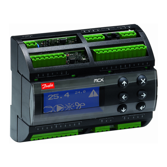
Рисунок 1. Внешний вид контроллера Danfoss MCX06D.
Основные технические характеристики контроллера:
Напряжение питания =20-60 В, ≈24 В ±15% 50/60 Гц;
Потребляемая мощность 9 ВА;
Изоляция между цепями питания и цепями управления.
Таблица 3. Описание входов/выходов контроллера Danfoss MCX06D.
| Входы/Выходы | Тип | К-во | Обозначение | |
| Входы | Дискретные | Для беспотенциальных контактов, потребляемый ток 5 мА | 8 | DI1…DI8 |
| Аналоговые | NTC,0…1В, 0…5В | 2 | AI1, AI2 | |
| универсальные | 2 | AI3, AI4 | ||
| Выходы | Дискретные | Нормально открытые контакты, максимальный ток 5 А, =30 В, ≈250В | 5 | C1-NO1, C2-NO2, C3-NO3, C4-NO4, C5-NO5 |
| Перекидной контакт,
максимальный ток 8 А, =30 В, ≈250В |
1 | NC6-C6-NO6 | ||
| Аналоговые | 0…10 В, ШИМ, ФИМ | 2 | AO1, AO2 | |
| ШИМ, ФИМ | 1 | AO3 |