
Для диагностики текущего состояния программируемых логических контроллеров фирмы Omron в первую очередь необходимо знать назначение индикаторов модуля ЦПУ. При наличии критических или некритических ошибок необходимо подключиться к контроллеру с помощью программного обеспечения CX-Programmer и посмотреть журнал ошибок. Также для детального описания ошибок пользуйтесь руководством по эксплутации.
Обратитесь в наш сервисный центр, если не можете разобраться с ошибкой сами, и мы поможем Вам.

Клиентоориентированность
Быстро отвечаем на запрос и сопровождаем клиента от первого звонка. Осуществляем поддержку после завершения проекта. Наша задача — реализовать проект, и при этом сэкономить ваше время и средства. Для нас каждый клиент является VIP-клиентом.

Оптимальные цены
Благодаря системному подходу мы выполняем только необходимые этапы разработки и производства. А хорошие взаимоотношения с поставщиками обеспечивают низкие закупочные цены. В сумме это дает лучшее ценовое предложение для Вас.

Поэтапная оплата
Организуем поэтапную оплату, чтобы вы платили только за выполненную часть работ.

Работают профессионалы
Наши специалисты имеют профильное образование и большой практический опыт разработки и внедрения автоматизированных систем в разных отраслях промышленности. Регулярно проходят повышение квалификации и обучение, как в нашем учебном центре, так и в центрах производителей оборудования.

Используем надежную технику
В наших проектах мы используем только качественные комплектующие мировых и российских производителей.

Полный комплект документов
Вы получаете вместе с оборудованием полный пакет документов: паспорт, электрические и монтажные схемы, инструкции по эксплуатации. Все элементы, провода и кабели имеют маркировку.
Табл.1.
| Индикатор | Состояние | Значение |
|---|---|---|
| «POWER» (зеленый) |
Светится | Питание включено. |
| Не светится | Питание выключено. | |
| «RUN» (зеленый) |
Светится | Светится, когда ПЛК нормально работает в режиме «Мониторинг» (MONITOR) или «Выполнение» (RUN) и выполняется программа. |
| Мигает | Ошибка режима загрузки системы или ошибка настройки DIP-переключателя. | |
| Не светится | ПЛК прекратил работу, оставаясь в режиме «Программирование», либо прекратил работу из-за критической ошибки, либо загружает данные из системы. | |
| «ERR/ALM» (красный) |
Светится | Функция самодиагностики обнаружила критическую ошибку (включая выполнение команды FALS(007)) или аппаратную ошибку (ошибку сторожевого таймера). Модуль ЦПУ прекратит работу, все выходы модулей выходов будут выключены. |
| Мигает | Функция самодиагностики обнаружила некритическую ошибку (включая выполнение команды FAL(006)). Модуль ЦПУ продолжит работу. | |
| Не светится | Модуль ЦПУ работает в нормальном режиме. | |
| «INH» (желтый) |
Светится | Включился бит выключения выходов (A500.15). Все выходы модулей выходов будут выключены. |
| Не светится | Выключился бит выключения выходов (A500.15). | |
| «PRPHL» (желтый) |
Мигает | Модуль ЦПУ осуществляет обмен данными (передачу или прием) через периферийный порт (или USB). |
| Не светится | Модуль ЦПУ не осуществляет обмен данными через периферийный порт (или USB). | |
| «COMM» (желтый) |
Мигает | Модуль ЦПУ осуществляет обмен данными (передачу или прием) через последовательный порт (RS-232C). |
| Не светится | Модуль ЦПУ не осуществляет обмен данными (передачу или прием) через последовательный порт (RS-232C). | |
| «BKUP» (желтый) |
Светится | Производится сохранение резервной копии программы пользователя и данных области параметров во флэш-память модуля ЦПУ или восстановление этих данных из флэш памяти после включения питания ПЛК. |
| Не светится | Запись данных во флэш-память не производится. |
На рис.1. представлена лицевая панель ЦПУ контроллера серии CJ2. Индикаторы ЦПУ предшествующей серии контроллера CJ1 такие же.
На рис.2. показано расположение индикаторов на модуле ЦПУ контроллера серии CP1E, CP1L и CP1H.
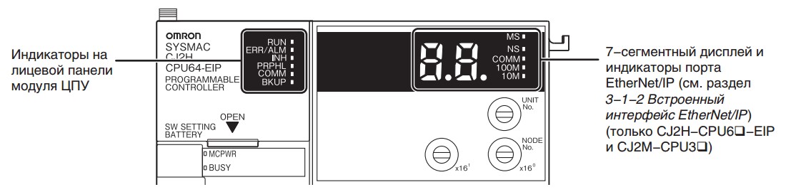
Рис.1.
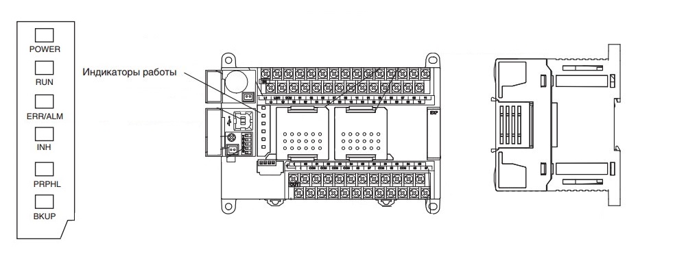
Рис.2.
Нужна консультация?
Задавайте свои вопросы и получите ответ бесплатно!
 Частотные преобразователи относятся к сложной промышленной электронике достаточно дорогой и в тоже время широко распространенной по всему миру. На сегодняшний день трудно себе даже представить какое-либо производство, на котором бы не работало данное промышленное оборудование.
К сожалению, в процессе эксплуатации выходит из строя даже самое надежное промышленное оборудование. В данной статье мы разберем частотный преобразователь Omron, точнее ошибки частотного преобразователя Omron mx2, коды ошибок и их расшифровка. Частотники в наше время нашли широкое применения в абсолютно всех сферах промышленности управляя как мини моторами в оргтехнике, так и гигантскими двигателями в горнодобывающей промышленности.
Для простоты общения со столь сложной электроникой все частотные преобразователи оснащены небольшими дисплеями с помощью которых выводятся информационные сообщения с кодами ошибок, расшифровав которые можно сразу же узнать причину ее возникновения. Если учесть распространенность данной промышленной электроники, то появляется острая нужда в расшифровке кодов ошибок частотных преобразователей.
Существует несколько видов ошибок, некоторые из них можно устранить автоматически, а некоторые возможно исправить только, обратившись в специализированный сервисный центр. В таблицах ниже приведены все коды ошибок частотного преобразователя Omron и их расшифровка, то есть причина по которой возникла та или иная ошибка.
|
Код ошибки |
Расшифровка |
Причина возникновения ошибки |
|
E01 |
Превышение тока при вращении с постоянной скоростью. |
Короткое замыкание на выходе преобразователя частоты, заблокирован вал двигателя или тяжелая нагрузка. По одной из этих причин чрезмерно возрос ток преобразователя частоты, что привело к аварийному отключению выхода преобразователя частоты. Допущена ошибка при подключении цепей двигателя с двумя напряжениями питания. |
|
E02 |
Превышение тока во время торможения. |
|
|
E03 |
Превышение тока во время разгона. |
|
|
E04 |
Превышение тока при других режимах. |
|
|
E05 |
Защита от перегрузки. |
Когда электронная функция тепловой защиты распознает перегрузку двигателя, преобразователь частоты переходит в состояние ошибки и снимает напряжение со своего выхода. Проверьте, допускает ли ваша система более плавный (медленный) разгон, позволяющий снизить пиковые токи F002/F202/A092/A292). Проверьте, правильно ли заданы параметры двигателя (H020…H034) с учетом выбранного метода управления двигателем (A044/A244). |
|
E06 |
Защита от перегрузки тормозного резистора. |
Если коэффициент включения тормозного резистора превышает значение параметра «b090», эта функция защиты отключает выход преобразователя частоты и индицирует код ошибки. |
|
E07 |
Защита от повышенного напряжения. |
Напряжение шины постоянного тока превысило пороговый уровень вследствие возврата энергии двигателем в генераторном режиме. |
|
E08 |
Ошибка ЭСППЗУ. |
При наличии ошибок в работе встроенной микросхемы ЭСППЗУ из-за воздействия помех или повышенной температуры преобразователь частоты переходит в состояние ошибки и отключает свой выход. |
|
E09 |
Ошибка пониженного напряжения. |
Падение напряжения внутренней шины постоянного тока ниже порогового уровня приводит к отказу схемы управления. Пониженное напряжение также может быть причиной чрезмерного нагрева двигателя или низкого вращающего момента. Преобразователь частоты сигнализирует ошибку и отключает свой выход. |
|
E10 |
Ошибка определения тока. |
При возникновении ошибки во внутренней системе определения тока преобразователь частоты снимает напряжение со своего выхода и индицирует код ошибки. |
|
E11 |
Ошибка ЦПУ. |
Произошел сбой в работе встроенного ЦПУ, поэтому преобразователь частоты перешел в состояние ошибки и снял напряжение с двигателя. |
|
E12 |
Внешнее отключение выход. |
Поступил сигнал на дискретный вход, которому была назначена функция «EXT». Преобразователь частоты перешел в состояние ошибки и снял напряжение с двигателя. |
|
E13 |
USP. |
В момент подачи питания на преобразователь частоты сигнал «Ход» уже присутствовал, однако в преобразователе частоты была включена защита от безнадзорного запуска (USP). Преобразователь частоты перешел в состояние ошибки и не перейдет в режим «Ход», пока не будет сброшена ошибка. |
|
E14 |
Замыкание на землю. |
Во время подготовки к работе после включения питания преобразователь частоты может обнаруживать наличие коротких замыканий в цепях между выходом преобразователя частоты и двигателем. Данная функция защищает преобразователь частоты, но не защищает людей. |
|
E15 |
Превышение входного напряжения. |
После пребывания в режиме останова дольше 100 секунд преобразователь частоты проверяет вход на отсутствие повышенного напряжения. Если напряжение на входе превышает допустимый уровень, преобразователь частоты переходит в состояние ошибки. После устранения ошибки преобразователь частоты вновь может перейти в режим хода. |
|
E21 |
Отключение при срабатывании тепловой защиты. |
Если внутренняя температура преобразователя частоты становится выше порогового значения, тепловой датчик преобразователя частоты распознает чрезмерно высокую температуру силовых элементов и сигнализирует ошибку, снимая напряжение с выхода преобразователя частоты. |
|
E22 |
Ошибка связи ЦПУ. |
При возникновении ошибки обмена данными между двумя ЦПУ преобразователь частоты отключает свой выход и отображает код ошибки. |
|
E25 |
Ошибка силовой схемы (*3). |
Если установившееся состояние источника питания не может быть распознано вследствие воздействия помех или повреждения какого-либо элемента в цепи первичного электропитания, преобразователь частоты отключает свой выход. |
|
E30 |
Ошибка преобразователя частоты. |
При кратковременной перегрузке по току ПЧ отключит выход IGBT-модуля с целью защиты элементов силовой цепи. После отключения вследствие срабатывания данной функции защиты ПЧ не может возобновить работу. |
|
E35 |
Термистор. |
Если к клеммам [5] и [L] подключен термистор и преобразователь частоты определил, что температура слишком высока, выход преобразователя частоты отключается и действует состояние ошибки. |
|
E36 |
Ошибка тормоза. |
Если параметру b120 (Включение управления тормозом) назначено значение «01», преобразователь частоты отключает выход, если после выдачи сигнала отпускания тормоза в течение времени ожидания сигнала подтверждения от тормоза (b124) сигнал подтверждения от тормоза не поступает. Или если выходной ток не достигает заданного уровня отпускания тормоза (b126) в течение времени отпускания тормоза (b121). |
|
E37 |
Безопасный останов. |
Подан сигнал безопасного останова. |
|
E38 |
Защита от перегрузки в области малых скоростей. |
Если во время вращения двигателя с очень низкой скоростью возникает перегрузка, преобразователь частоты распознает перегрузку и снимает напряжение со своего выхода. |
|
E40 |
Подключение панели управления. |
Если клавишная панель управления отсоединяется от преобразователя частоты, преобразователь частоты отключает свой выход и индицирует код ошибки. |
|
E41 |
Ошибка интерфейса связи Modbus. |
Если в качестве действия при возникновении ошибки связи выбрано «отключение выхода» (C076=00), выход преобразователя частоты отключается по истечении контрольного времени. |
|
E43 |
Неверная команда EzSQ. |
Повреждена программа в памяти преобразователя частоты либо вход «PRG» был включен при отсутствии программы в памяти преобразователя частоты. |
|
E44 |
Ошибка числа вложений EzSQ. |
В подпрограммах, операторе «if» или цикле «for-next» допущено более восьми уровней вложения. |
|
E45 |
Ошибка команды EzSQ. |
Преобразователь частоты обнаружил программу, которая не может быть выполнена. |
|
E50 |
EzSQ, аварийное событие пользователя (0…9). |
Если возникает аварийное событие, определенное пользователем, преобразователь частоты отключает свой выход и отображает код ошибки. |
|
E51 |
||
|
E52 |
||
|
E53 |
||
|
E54 |
||
|
E55 |
||
|
E56 |
||
|
E57 |
||
|
E58 |
||
|
E59 |
||
|
E60 |
Ошибки дополнительных карт (ошибка в подключенной дополнительной карте, значение зависит от типа подключенной карты). |
Эти ошибки зарезервированы для дополнительных карт. Значения кодов ошибок для разных дополнительных карт могут отличаться. Значение кода ошибки для конкретной дополнительной карты смотрите в руководстве пользователя и документации на эту карту. |
|
E61 |
||
|
E62 |
||
|
E63 |
||
|
E64 |
||
|
E65 |
||
|
E66 |
||
|
E67 |
||
|
E68 |
||
|
E69 |
||
|
E80 |
Отсоединение энкодера. |
В случае отсоединения энкодера, обнаружения ошибки подключения энкодера, отказа энкодера или применения энкодера без выходного формирователя уровня RS-422 преобразователь частоты отключает свой выход и отображает код ошибки, показанный слева. |
|
E81 |
Чрезмерная скорость. |
Если скорость вращения двигателя становится выше, чем «максимальная частота (A004) x уровень обнаружения ошибки превышения скорости (P026)», преобразователь частоты отключает свой выход и отображает код ошибки, показанный слева. |
|
E83 |
Ошибка отклонения положения. |
Если текущее положение ротора двигателя выходит за установленные границы позиционирования (P072-P073), преобразователь частоты отключает свой выход и отображает код ошибки. |
Коды предупреждений об ошибке при настройке параметров частотного преобразователя Omron
Частотный преобразователь показывает коды ошибок не только в процессе работы, но и на этапе настройки. Коды ошибок частотного преобразователя появляются в том случае если заданное значение вводимого параметра идет в разрез со значениями других параметров. В следующей таблице приведены все возможные коды ошибок частотного преобразователя Omron mx2 выводимые частотником при конфликте параметров в процессе настройки преобразователя.
|
Коды предупреждения об ошибке |
Причины вывода кода предупреждения об ошибке |
||
|
001 |
Верхняя граница частоты (A061). |
> |
Максимальная частота (A004). |
|
002 |
Нижняя граница частоты (A062). |
> |
|
|
005 |
Установка выходной частоты (F001) Предустановленная частота 0 (A020). |
> |
|
|
015 |
Установка выходной частоты (F001) Предустановленная частота 0 (A020). |
> |
Верхняя граница частоты (A061). |
|
025 |
Нижняя граница частоты (A062). |
> |
Установка выходной частоты (F001) Предустановленная частота 0 (A020). |
|
031 |
Начальная частота (A082). |
> |
Верхняя граница частоты (A061). |
|
032 |
> |
Нижняя граница частоты (A062). |
|
|
035 |
> |
Установка выходной частоты (F001) Предустановленная частота 0 (A020). |
|
|
036 |
> |
Предустановленная частота 1…15 (A021-A035). |
|
|
037 |
> |
Частота толчкового хода (A038). |
|
|
085 |
Установка выходной частоты (F001) Предустановленная частота 0 (A020). |
= |
Частота пропуска (A063/A063/A063±A064/A066/A068). |
|
086 |
Предустановленная частота 1…15 (A021-A035). |
||
|
091 |
Частота произв. V/f-хар. 7. |
> |
Верхняя граница частоты (A061). |
|
092 |
> |
Нижняя граница частоты (A062). |
|
|
095 |
> |
Установка выходной частоты (F001) Предустановленная частота 0 (A020). |
|
|
201 |
Верхняя граница частоты (A261). |
> |
Максимальная частота (A204). |
|
202 |
Нижняя граница частоты (A262). |
> |
|
|
205 |
Установка выходной частоты (F001) Предустановленная частота 0 (A220). |
> |
|
|
015 |
> |
Верхняя граница частоты (A261). |
|
|
225 |
Нижняя граница частоты (A262). |
> |
Установка выходной частоты (F001) Предустановленная частота 0 (A220). |
|
231 |
Начальная частота (A082). |
> |
Верхняя граница частоты (A261). |
|
232 |
> |
Нижняя граница частоты (A262). |
|
|
235 |
> |
Установка выходной частоты (F001) Предустановленная частота 0 (A220). |
|
|
285 |
Установка выходной частоты (F001) Предустановленная частота 0 (A220). |
= |
Частота пропуска (A063/A063/A063±A064/A066/A068). |
|
291 |
Частота произв. V/f-хар. 7. |
> |
Верхняя граница частоты (A261). |
|
292 |
> |
Нижняя граница частоты (A262). |
|
|
295 |
> |
Установка выходной частоты (F001) Предустановленная частота 0 (A220). |
Конечно, ошибку частотного преобразователя можно сбросить, но для предотвращения рецидива мы настоятельно советуем найти первопричину вызвавшую аварийную остановку оборудования. Преобразователь частоты Omron mx2 хранит в своей памяти пять последних ошибок, посмотреть которые можно с помощью функции контроля (dxxx). Воспользуйтесь параметром d081 и выберете интересующую вас ошибку. Ошибки хранятся в параметрах от d082 до d086 и при возникновении новой перезаписывают первый параметр смещая их из параметров d081 — d085 в параметры d082 — d086 при этом затирается самая старшая ошибка частотного преобразователя Omron находившаяся в параметре d086.
Ниже приведена схема меню режима мониторинга, которая наглядно показывает доступ к кодам ошибок частотного преобразователя Omron mx2. В случае возникновения ошибки воспользуйтесь этой схемой для их просмотра. Для полной ясности в параметре d081 хранится самая последняя ошибка, а в параметре d086 самая старшая.

После выявления причины возникновения ошибки и ее устранения можно сбросить ошибки частотного преобразователя Omron и восстановить заводские настройки частотника.

Восстановление заводских настроек частотного преобразователя Omron.
|
Функция (b) |
||
|
Код функции |
Название функции |
Описание функции |
|
b084 |
Режим инициализации (параметров или журнала аварийных отключений). |
Выберите инициализируемые данные (5 возможных кодов): 00 Инициализация выключена. 01 Очистка журнала аварийных отключений. 02 Инициализация всех параметров. 03 Очистка журнала аварийных отключений и инициализация всех параметров. 04 Очистка журнала аварийных отключений, инициализация всех параметров и программы EzSQ. |
|
b094 |
Выбор инициализируемых данных. |
Выберите инициализируемые параметры (возможно 4 кода): 00 Все параметры. 01 Все параметры, кроме входных/выходных клемм и интерфейса связи. 02 Только параметры, зарегистрированные в Uxxx. 03 Все параметры, кроме параметров, зарегистрированных в Uxxx, и параметра b037. |
|
b085 |
Выбор зоны для начальных данных. |
Выберите зону применения преобразователя частоты для инициализации данных: 00 (Япония/США). 01 (Европа). |
|
b080 |
Запуск инициализации. |
Служит для выполнения инициализации в соответствии с введенными значениями параметров b084, b085 и b094. Два возможных кода: 00 Инициализация выключена. 01 Выполнить инициализацию. |
Значение параметра b084 не сохраняется в памяти ЭСППЗУ чтобы исключить случайную инициализацию данных.
Сброс ошибок и Ремонт частотников в сервисном центре
Компания «Кернел» производит ремонт промышленной электроники и оборудования с 2002 года. За это время мы накопили колоссальный опыт в том числе опыт в ремонте частотных преобразователей. ![]() Ремонт подобной промышленной электроники ответственное и сложное занятие, требующие максимальной отдачи, профессионализма и максимально полной материальной базе.
Ремонт подобной промышленной электроники ответственное и сложное занятие, требующие максимальной отдачи, профессионализма и максимально полной материальной базе.
Специалисты нашего сервисного центра уделяют максимальное внимание к качеству исполнения ремонта, программирования и настройке промышленного преобразователя частоты, не зависимо от производителя данного промышленного оборудования. Именно поэтому мы смело даем гарантию на все выполненные работы шесть месяцев.
Ремонт частотных преобразователей Omron производится исключительно с использованием оригинальных запасных частей, на компонентном уровне с применением высокотехнологичного оборудования, квалифицированным персоналом с инженерным образованием.
Если на вашем производстве появились проблемы с частотным преобразователем, которые вы не можете решить самостоятельно, мы всегда рады вам помочь. Обращайтесь в сервисный центр «Кернел». Специалисты нашей компании в минимальные сроки проведут глубокую диагностику и последующий ремонт частотного преобразователя. Оставьте заказ на ремонт оборудования используя форму на сайте, либо свяжетесь с нашими менеджерами, сделать это очень просто.
Как с нами связаться
У вас остались вопросы, связанные с ремонтом, программированием и настройкой промышленной электроники? Задайте их нашим менеджерам. Связаться с ними можно несколькими способами:

- Заказав обратный звонок (кнопка в правом нижнем углу сайта)
- Посредством чата (кнопка расположена с левой стороны сайта)
- Позвонив по номеру телефона:
- +7(8482) 79-78-54;
- +7(8482) 55-96-39;
- +7(917) 121-53-01
- Написав на электронную почту: 89171215301@mail.ru
Далеко не полный список производителей промышленной электроники и оборудования, ремонтируемой в нашей компании.
-
Contents
-
Table of Contents
-
Troubleshooting
-
Bookmarks
Related Manuals for Omron NJ Series
Summary of Contents for Omron NJ Series
-
Page 1
Machine Automation Controller NJ-series Troubleshooting Manual NJ501-1500 NJ501-1400 NJ501-1300 NJ301-1200 NJ301-1100 W503-E1-05… -
Page 2
OMRON. No patent liability is assumed with respect to the use of the information contained herein. Moreover, because OMRON is constantly striving to improve its high-quality products, the information contained in this manual is subject to change without notice. -
Page 3: Introduction
Introduction Introduction Thank you for purchasing an NJ-series CPU Unit. This manual contains information that is necessary to use the NJ-series CPU Unit. Please read this manual and make sure you understand the functionality and performance of the NJ-series CPU Unit before you attempt to use it in a control system.
-
Page 4: Relevant Manuals
Relevant Manuals Relevant Manuals There are three manuals that provide basic information on the NJ-series CPU Units: the NJ-series CPU Unit Hardware User’s Manual, the NJ-series CPU Unit Software User’s Manual, and the NJ-series Instructions Reference Manual. Most operations are performed from the Sysmac Studio Automation Software. Refer to the Sysmac Stu- dio Version 1 Operation Manual (Cat.
-
Page 5: Manual Structure
Manual Structure Manual Structure Page Structure The following page structure is used in this manual. Level 1 heading 4 Installation and Wiring Level 2 heading Mounting Units Level 3 heading Level 2 heading Gives the current headings. Level 3 heading 4-3-1 Connecting Controller Components The Units that make up an NJ-series Controller can be connected simply by pressing the Units together…
-
Page 6
Manual Structure Precaution on Terminology In this manual, “download” refers to transferring data from the Sysmac Studio to the physical Controller and “upload” refers to transferring data from the physical Controller to the Sysmac Studio. For the Sysmac Studio, synchronization is used to both upload and download data. Here, “synchronize” means to automatically compare the data for the Sysmac Studio on the computer with the data in the physical Controller and transfer the data in the direction that is specified by the user. -
Page 7: Sections In This Manual
Sections in this Manual Sections in this Manual Overview of Errors Error Troubleshooting Methods Error Tables Index NJ-series Troubleshooting Manual (W503)
-
Page 8
Sections in this Manual NJ-series Troubleshooting Manual (W503) -
Page 9: Table Of Contents
CONTENTS CONTENTS Introduction………………….. 1 Relevant Manuals…………………. 2 Manual Structure …………………. 3 Sections in this Manual……………….. 5 Read and Understand this Manual…………….9 Safety Precautions ………………..13 Precautions for Safe Use ………………14 Precautions for Correct Use ……………… 15 Regulations and Standards ………………. 16 Unit Versions………………….
-
Page 10
CONTENTS Section 3 Error Tables Errors by Source……………………3-2 3-1-1 Interpreting Error Descriptions ………………..3-2 3-1-2 Errors in the PLC Function Module ………………… 3-2 3-1-3 Errors in the Motion Control Function Module…………….3-42 3-1-4 Errors in the EtherNet/IP Function Module …………….3-68 3-1-5 Errors in the EtherCAT Master Function Module…………… -
Page 11: Read And Understand This Manual
WHETHER SUCH CLAIM IS BASED ON CONTRACT, WARRANTY, NEGLIGENCE, OR STRICT LIABILITY. In no event shall the responsibility of OMRON for any act exceed the individual price of the product on which liability is asserted. IN NO EVENT SHALL OMRON BE RESPONSIBLE FOR WARRANTY, REPAIR, OR OTHER CLAIMS…
-
Page 12
Application Considerations SUITABILITY FOR USE OMRON shall not be responsible for conformity with any standards, codes, or regulations that apply to the combination of products in the customer’s application or use of the products. At the customer’s request, OMRON will provide applicable third party certification documents identifying ratings and limitations of use that apply to the products. -
Page 13
Performance data given in this manual is provided as a guide for the user in determining suitability and does not constitute a warranty. It may represent the result of OMRON’s test conditions, and the users must correlate it to actual application requirements. Actual performance is subject to the OMRON Warranty and Limitations of Liability. -
Page 14
Read and Understand this Manual NJ-series Troubleshooting Manual (W503) -
Page 15: Safety Precautions
Safety Precautions Safety Precautions Refer to the following manuals for safety precautions. • NJ-series CPU Unit Hardware User’s Manual (Cat No. W500) • NJ-series CPU Unit Software User’s Manual (Cat No. W501) NJ-series Troubleshooting Manual (W503)
-
Page 16: Precautions For Safe Use
Precautions for Safe Use Precautions for Safe Use Refer to the following manuals for precautions for the safe use of the NJ-series Controller. Installation precautions are also provided for the NJ-series CPU Unit and the NJ-series Controller sys- tem. • NJ-series CPU Unit Hardware User’s Manual (W500) •…
-
Page 17: Precautions For Correct Use
Precautions for Correct Use Precautions for Correct Use Refer to the following manuals for precautions for the correct use of the NJ-series Controller. Installation precautions are also provided for the NJ-series CPU Unit and the NJ-series Controller sys- tem. • NJ-series CPU Unit Hardware User’s Manual (W500) •…
-
Page 18: Regulations And Standards
Concepts EMC Directive OMRON devices that comply with EC Directives also conform to the related EMC standards so that they can be more easily built into other devices or the overall machine. The actual products have been checked for conformity to EMC standards.* Whether the products conform to the standards in the system used by the customer, however, must be checked by the customer.
-
Page 19
The NJ-series Controllers comply with the following shipbuilding standards. Applicability to the ship- building standards is based on certain usage conditions. It may not be possible to use the product in some locations. Contact your OMRON representative before attempting to use a Controller on a ship. -
Page 20: Unit Versions
Unit Versions Unit Versions Unit Versions A “unit version” has been introduced to manage CPU Units in the NJ Series according to differences in functionality accompanying Unit upgrades. Notation of Unit Versions on Products The unit version is given on the ID information label of the products for which unit versions are man- aged, as shown below.
-
Page 21
Unit Versions Right-click any open space in the Unit Editor and select Production Information. The Production Information Dialog Box is displayed. Simple Display Detailed Display In this example, “Ver.1.00” is displayed next to the unit model. The following items are displayed. CPU Unit CJ-series Units Unit model… -
Page 22
Unit Versions Unit Versions and Sysmac Studio Versions The events that can occur depend on the unit versions of the NJ-series CPU Unit and the EtherCAT slaves. You must use the corresponding version of Sysmac Studio to display events that were added for version upgrades when troubleshooting from the Sysmac Studio or from the Troubleshooter on an NS- series PT. -
Page 23: Related Manuals
CPU Unit Hardware User’s Manual (Cat. No. tions that are provided W500), NJ-series CPU Unit Software User’s Manual by OMRON. (Cat. No. W501) and NJ-series CPU Unit Motion Control User’s Manual (Cat. No. W507). NJ-series CPU Unit Built-…
-
Page 24
Related Manuals Manual name Cat. No. Model numbers Application Description NJ-series Troubleshoot- W503 NJ501-@@@@ Learning about the Concepts on managing errors that may be detected ing Manual NJ301-@@@@ errors that may be in an NJ-series Controller and information on individ- detected in an NJ-series ual errors are described. -
Page 25
Related Manuals Manual name Cat. No. Model numbers Application Description FQ-M-series Specialized Z314 FQ-MS12@ Leaning how to connect Describes the following information for the FQ-M- Vision Sensor for Posi- FQ-M-series Special- series Specialized Vision Sensor for Positioning: tioning User’s Manual ized Vision Sensor for installation, wiring methods, parameter settings Positioning. -
Page 26: Revision History
Revision History Revision History A manual revision code appears as a suffix to the catalog number on the front and back covers of the manual. W503-E1-05 Cat. No. Revision code Revision code Date Revised content July 2011 Original production March 2012 Added information related to the upgrade to unit version 1.01, made additions and changes to events related to the addition of devices that can be connected, and corrected mistakes.
-
Page 27: Overview Of Errors
Overview of Errors This section provides information that is required to troubleshoot errors. It introduces the types of errors that can occur on an NJ-series Controller, the operation that occurs in response to errors, and the methods you can use to check for errors. Refer to Sec- tion 2 Error Troubleshooting Methods for information on troubleshooting errors.
-
Page 28: Overview Of Nj-Series Errors
1 Overview of Errors Overview of NJ-series Errors You manage all of the errors that occur on the NJ-series Controller as events. The same methods are used for all events. This allows you to see what errors have occurred and find corrections for them with the same methods for the entire range of errors that is managed (i.e., CPU Unit, EtherCAT slaves,* and CJ-series Units).
-
Page 29: Cpu Unit Status
1 Overview of Errors Non-fatal Errors These errors are detected and managed with the event management function of the NJ-series Con- troller. You can confirm these errors with the Sysmac Studio or an NS-series PT. Refer to 1-3 Non-fatal Errors for error types and confirmation methods for non-fatal errors. 1-1-2 CPU Unit Status You can check the operating status of the CPU Unit with the PWR, RUN, and ERROR indicators on the…
-
Page 30: Fatal Errors
1 Overview of Errors Fatal Errors 1-2-1 Types of Fatal Errors This section describes the errors that cause the operation of the NJ-series CPU Unit to stop. Software connections to the Sysmac Studio or an NS-series PT cannot be made if there is a fatal error in the Controller.
-
Page 31: Non-Fatal Errors
1 Overview of Errors Non-fatal Errors Non-fatal errors that occur are managed as events in the NJ-series Controller. You can check the event to find out what type of error occurred. 1-3-1 Types of Non-fatal Errors Overview of Controller Events (Errors and Information) You use the same methods to manage all of the events that occur on the NJ-series Controller.
-
Page 32
1 Overview of Errors Details on Controller Events (Errors and Information) Sources of Controller Events The Event source information indicates the location where an event occurred. The event source identifies the particular function module in the CPU Unit in which the event occurred. For some func- tion modules, there is more detailed information about the event source. -
Page 33
1 Overview of Errors • Information Events that are classified as information provide information that do not indicate errors. You can change the event level for some events. Refer to the NJ-series CPU Unit Software User’s Man- ual (Cat. No. W501) for details on changing event levels. Refer to 3-1 Errors by Source in this manual to see the events for which you can change the event level. -
Page 34
1 Overview of Errors Controller Controller errors Event level information Major fault Partial fault Minor fault Item Observation Information level level level RUN out- put on Power Supply Unit User pro- Stops. Continues. Continues. Continues. Continues. gram execu- tion sta- series Unit Outputs… -
Page 35
1 Overview of Errors Operation in the Function Module Where an Error Event Occurred Event level Major fault level Partial fault level Minor fault level Observation Function module PLC Function User program execution Operation continues. Module stops. All axes stop. (The stop All axes stop. -
Page 36
1 Overview of Errors Unit CPU Unit operation Unit or slave operation CJ-series Basic I/O Unit Refreshing is stopped. • All outputs are turned OFF. • All inputs are turned OFF. CJ-series Special Unit Refreshing is stopped. Depends on the Unit operating specifications (the ERH indicator lights). -
Page 37
1 Overview of Errors First digit of the Classification Meaning code (hex) Hardware errors An error caused by a hardware problem such as an inter- nal part malfunction, contact failure, temperature error, undervoltage, overvoltage, or overcurrent. Data errors An error caused by incorrectly saved data or data cor- ruption in the Controller. -
Page 38: Checking For Non-Fatal Errors
1 Overview of Errors Variable Name _MC_AX[0..63].Obsr.Code Axis Observation Code _MC_GRP[0..31].MFaultLvl.Code Axes Group Minor Fault Code _MC_GRP[0..31].Obsr.Code Axes Group Observation Code For descriptions of the error codes for the Motion Control Function Module or basic instructions, refer to the descriptions of the corresponding event codes. Refer to the NJ-series CPU Unit Motion Control User’s Manual (Cat.
-
Page 39
• Lit: Errors for which normal status cannot be recovered through user actions (i.e., errors for which you must replace the CPU Unit or contact your OMRON representative). • Flashing: Errors for which normal status can be recovered through user actions. -
Page 40: Resetting Non-Fatal Errors
1 Overview of Errors Current Errors Open the Controller Error Tab Page on the NS-series PT’s Troubleshooter to check the current error’s event name, event code, level, source, source details, time, details, and attached information 1 to 4. Observations are not displayed on this tab page. …
-
Page 41
1 Overview of Errors Always confirm safety at the connected equipment before you reset Controller errors for a CJ- series Special Unit. When the Controller error is reset, the Unit where the Controller error with an event level of observation or higher will be restarted. Before you reset all errors, confirm that no Controller errors with an event level of observation or higher have occurred for the CJ-series Special Unit. -
Page 42
1 Overview of Errors 1-16 NJ-series Troubleshooting Manual (W503) -
Page 43: Error Troubleshooting Methods
Error Troubleshooting Methods This section describes troubleshooting methods for specific errors. 2-1 Troubleshooting Flowcharts ……..2-2 2-1-1 Checking to See If the CPU Unit Is Operating .
-
Page 44: Troubleshooting Flowcharts
2 Error Troubleshooting Methods Troubleshooting Flowcharts This section provides basic error identification and troubleshooting flowcharts. Use them when an error occurs in the NJ-series Controller. 2-1-1 Checking to See If the CPU Unit Is Operating When an error occurs in the NJ-series Controller, use the following flowchart to determine whether the error is a fatal error or a non-fatal error.
-
Page 45: Troubleshooting Flowchart For Non-Fatal Errors
2 Error Troubleshooting Methods 2-1-2 Troubleshooting Flowchart for Non-fatal Errors For a non-fatal error, use the Sysmac Studio or an NS-series PT to troubleshoot the error with the fol- lowing flowchart. You can use the indicators to check the following: •…
-
Page 46: Troubleshooting Fatal Errors
2 Error Troubleshooting Methods Troubleshooting Fatal Errors The section describes the procedure to troubleshoot fatal errors. Power Supply Error Cause Correction Power is not being input. Turn ON the power. The voltage is outside of the allowable Check the Controller’s power supply system, and correct it so that the range for the power supply.
-
Page 47: Troubleshooting Non-Fatal Errors
2 Error Troubleshooting Methods Troubleshooting Non-fatal Errors 2-3-1 Identifying and Resetting Errors with the Sysmac Studio Troubleshooting functions are provided by the Sysmac Studio. You can use the troubleshooting func- tions to identify errors that occur in a Controller, and reset the errors. Displaying Errors on the Sysmac Studio If an error occurs while the Sysmac Studio is online with the CPU Unit, the Sysmac Studio notifies the user of the error in the Controller Status Pane.
-
Page 48
2 Error Troubleshooting Methods Checking Current Errors and the Event Logs with the Sysmac Studio Checking Current Errors with the Sysmac Studio You can click the Controller Errors Tab in the Troubleshooting Window to read information on cur- rent errors in the Controller. The Controller Errors Tab Page lists the current errors in order of their levels. -
Page 49
2 Error Troubleshooting Methods Displaying Event Logs with the Sysmac Studio With Sysmac Studio, you can check a log of the Controller events that previously occurred on the Controller Event Log Tab Page. You can select the event logs and levels to display in the Display Settings Area. Information on the events that you specify are displayed in the detailed information area. -
Page 50
2 Error Troubleshooting Methods To eliminate the cause of the error, first select the item to perform from the Action and Correction list. When you select the appropriate step in the Action and Correction list, either the Jump to Error or Error Help Button is enabled, depending on the contents. -
Page 51: Identifying And Resetting Errors With An Ns-Series Pt
Identifying and Resetting Errors with an NS-series PT You can connect one of the following OMRON NS-series PTs to an NJ-series CPU Unit through an Eth- erNet/IP network, and use it to read and reset errors that occurred in the Controller. (The Trouble- shooter of the PT is used.)
-
Page 52
2 Error Troubleshooting Methods Resetting Errors with an NS-series PT You can use the Troubleshooter in an NS-series PT to reset errors that occur in the Controller. Before you attempt to reset a Controller error, isolate and remove the cause of the error. Click the Select Button in the List View to display information such as the error’s causes and correc- tions. -
Page 53: Identifying And Resetting Errors From The User Program
2 Error Troubleshooting Methods In order to reset the Controller errors, it is necessary to confirm your rights according to the operation authority settings for the Troubleshooter. Refer to the NS-series Programmable Terminals Programming Manual (Cat. No. V073) for details on the operation authority. 2-3-3 Identifying and Resetting Errors from the User Program In an NJ-series Controller, you can check for errors that have occurred from the user program.
-
Page 54
2 Error Troubleshooting Methods Example of Error Detection for the EtherCAT Master Function Module Name Data type Initial value Comment Trigger BOOL FALSE Get Condition EC_Error BOOL FALSE EtherCAT Master Error Flag EC_Error GetECError Trigger Level Code Resetting Controller Errors with Instructions You can use the instructions that are provided to reset errors in the user program to reset errors that occur in the Controller. -
Page 55: Checking For Errors With System-Defined Variables
2 Error Troubleshooting Methods 2-3-4 Checking for Errors with System-defined Variables The system-defined variables include an Error Status variable, which shows the error status. The fol- lowing diagram shows the structure of this variable. The system determines the error status of each level by logically ORing the error status information of the next lower level.
-
Page 56: Troubleshooting When You Cannot Go Online From The Sysmac Studio
2 Error Troubleshooting Methods Troubleshooting When You Cannot Go Online from the Sysmac Studio The section describes the procedure to troubleshoot when you cannot go online with the CPU Unit from the Sysmac Studio. 2-4-1 Causes and Correction When You Cannot Go Online from the Sysmac Studio The following table lists the possible causes when you cannot go online with the NJ-series CPU Unit from the Sysmac Studio.
-
Page 57: Troubleshooting For Each Cause
2 Error Troubleshooting Methods 2-4-2 Troubleshooting for Each Cause This section provides troubleshooting methods for incorrect settings, fault communications paths, and high system service loads. Troubleshooting Incorrect Settings and Faulty Communications Path If the Sysmac Studio cannot go online with the CPU Unit, troubleshoot the problem with the following flowchart.
-
Page 58
2 Error Troubleshooting Methods Remote Connection to Peripheral USB Port Sysmac Studio cannot connect to CPU Unit. Is power supplied to the Controller? Turn ON the power supply to the Controller. Can the Sysmac Studio go online with CPU Unit? Are the USB cable and Insert the cable connectors all the way Ethernet cables… -
Page 59
2 Error Troubleshooting Methods Direct Connection with EtherNet/IP Port Sysmac Studio cannot Sysmac Studio cannot connect to CPU Unit. connect to CPU Unit. Is power supplied to the Controller? Is power supplied to the Controller? Turn ON the power supply to the Controller. Turn ON the power supply to the Controller. -
Page 60
2 Error Troubleshooting Methods Ethernet Hub Connection Sysmac Studio cannot connect to CPU Unit. Is power supplied to the Controller? Turn ON the power supply to the Controller. Can the Sysmac Studio go online with CPU Unit? Insert the cable connectors at the personal computer,Ethernet switches, and the Controller until they lock into place. -
Page 61
2 Error Troubleshooting Methods Set the IP address for the personal computer. Use the default IP address for the Controller or Is the same IP address set for connect the Sysmac Studio to the Controller more than one node (computer with a USB cable and set the required IP or Controller) in the same address. -
Page 62
2 Error Troubleshooting Methods Safe Mode Operation If the Controller is started when the CPU Unit is in Safe Mode, the CPU Unit will start in PROGRAM mode even if the startup mode is set to RUN mode. This increases the ratio of system service pro- cessing that is performed by the CPU Unit, which makes it easier for the Sysmac Studio to go online with the CPU Unit. -
Page 63
Error Tables This section lists all of the errors (events) that can occur on NJ-series Controllers. 3-1 Errors by Source ……….3-2 3-1-1 Interpreting Error Descriptions . -
Page 64: Error Tables
3 Error Tables Errors by Source This section provides tables of errors (events) by source. Within each source, errors are given by func- tional classifications. Events that are not errors are also given in the tables. 3-1-1 Interpreting Error Descriptions The contents of the error tables are described below.
-
Page 65
3 Error Tables Errors for Self Diagnosis Level Event code Event name Meaning Assumed cause Reference Info 00090000 hex DIP Switch An error was • There is an error in the DIP NJ-series Setting Error detected in the DIP switch setting. CPU Unit switch setting. -
Page 66
3 Error Tables Level Event code Event name Meaning Assumed cause Reference Obs Info 00080000 hex Real-Time The real-time clock • The CPU Unit clock has failed. NJ-series Clock Failed in the CPU Unit CPU Unit failed. Hardware User’s Manual (Cat. -
Page 67
3 Error Tables Level Event code Event name Meaning Assumed cause Reference Info 10070000 hex SD Memory The power supply • The Controller power supply NJ-series Card Access to the Controller was turned OFF while the SD CPU Unit Power OFF was interrupted BUSY indicator was lit. -
Page 68
3 Error Tables Level Event code Event name Meaning Assumed cause Reference Obs Info 24050000 hex Duplicate The same unit num- • The same unit number is set for NJ-series Unit Number ber is set for more more than one Special I/O Unit CPU Unit than one Special or more than one CPU Bus… -
Page 69
3 Error Tables Level Event code Event name Meaning Assumed cause Reference Obs Info 80010000 hex Illegal Packet An illegal packet • Noise NJ-series Discarded was received during CPU Unit message communi- Hardware cations. The illegal User’s Manual packet was dis- (Cat. -
Page 70
3 Error Tables Errors Related to Controller Operation Level Event code Event name Meaning Assumed cause Reference Obs Info 10200000 hex User Pro- The user program • The user program or Controller NJ-series gram/Con- or Controller Con- Configurations and Setup are CPU Unit troller figurations and… -
Page 71
3 Error Tables Level Event code Event name Meaning Assumed cause Reference Info 10270000 hex Error in Start- An error was • An SD Memory Card is not NJ-series (Ver. 1.03) ing Auto- detected in pre-exe- inserted. CPU Unit matic cution checks for Hardware •… -
Page 72
3 Error Tables Level Event code Event name Meaning Assumed cause Reference Obs Info 10260000 hex Trace Setting The power supply • The power supply was inter- NJ-series Transfer Fail- was interrupted rupted while transferring the CPU Unit while transferring trace settings. -
Page 73
3 Error Tables Level Event code Event name Meaning Assumed cause Reference Info 102B0000 hex Restore An error was • An SD Memory Card is not NJ-series (Ver. 1.03) Operation detected in pre-exe- inserted. CPU Unit Failed to cution checks for a Hardware •… -
Page 74
3 Error Tables Level Event code Event name Meaning Assumed cause Reference Obs Info 90080000 hex Variable Changing a variable • Changing a variable to TRUE NJ-series Changed to to TRUE with forced with forced refreshing was CPU Unit TRUE with refreshing was specified by the user. -
Page 75
3 Error Tables Errors Related to FINS Communications Level Event code Event name Meaning Assumed cause Reference Info 14010000 hex CPU Bus An error was • The power supply to the Con- NJ-series Unit Setup detected in the troller was interrupted or com- CPU Unit Soft- Area Error memory check of… -
Page 76
3 Error Tables Level Event code Event name Meaning Assumed cause Reference Obs Info 80120000 hex Packet Dis- One or more pack- • A FINS response was received NJ-series carded ets were discarded. with the destination network CPU Unit Soft- address (DNA) set to the local ware User’s network and the destination… -
Page 77
3 Error Tables Instructions A version in parentheses in the Event code column is the unit version of the CPU Unit when the event code was added. Level Refer- Event code Event name Meaning Assumed cause ence Info 54010400 hex Input Value Out of An input parameter for an •… -
Page 78
3 Error Tables Level Refer- Event code Event name Meaning Assumed cause ence Info 54010406 hex Illegal Data Posi- A memory address or data • A memory address NJ-series tion Specified size that was specified for that was specified for Instruc- the instruction is not suit- an instruction was out-… -
Page 79
3 Error Tables Level Refer- Event code Event name Meaning Assumed cause ence Info 54010413 hex Undefined CJ- The required specification • The required AT speci- NJ-series series Memory is missing for a variable for fication is missing for a Instruc- Address which CJ-series Unit mem-… -
Page 80
3 Error Tables Level Refer- Event code Event name Meaning Assumed cause ence Info 54011400 hex SD Memory Card SD Memory Card access • An SD Memory Card NJ-series Access Failure failed when an instruction is either not inserted Instruc- was executed. -
Page 81
3 Error Tables Level Refer- Event code Event name Meaning Assumed cause ence Info 5401140B hex Too Many Files The maximum number of • The maximum number NJ-series Open open files was exceeded of open files was Instruc- when opening a file for an exceeded when open- tions Ref- instruction. -
Page 82
3 Error Tables Level Refer- Event code Event name Meaning Assumed cause ence Info 54011808 hex Communications More than 32 EtherCAT • More than 32 Ether- NJ-series Resource Overflow communications instruc- CAT communications Instruc- tions were executed at the instructions were exe- tions Ref- same time. -
Page 83
3 Error Tables Level Refer- Event code Event name Meaning Assumed cause ence Info 54011C04 hex CIP Timeout A CIP timeout occurred • A device does not NJ-series during execution of a CIP exist for the specified Instruc- communications instruc- IP address. -
Page 84
3 Error Tables Level Refer- Event code Event name Meaning Assumed cause ence Info 54012003 hex Status Error The status was not suit- • SktUDPRcv Instruc- NJ-series able for execution of the tion Instruc- instruction. tions Ref- • The socket is receiv- erence ing data. -
Page 85
3 Error Tables Level Refer- Event code Event name Meaning Assumed cause ence Info 54012006 hex Socket Timeout A timeout occurred for a • SktTCPAccept instruc- NJ-series socket service instruction. tion: There was no Instruc- request for a connec- tions Ref- tion from the remote erence node during the user-… -
Page 86
3 Error Tables Level Refer- Event code Event name Meaning Assumed cause ence Info 54012400 hex No Execution Right An instruction to change • An instruction to NJ-series (Ver. 1.02) the settings of an Ether- change the settings of Instruc- Net/IP port was executed the built-in EtherNet/IP tions Ref-… -
Page 87
W502) fies phase Z (_mcEncoderMark) as the trigger conditions was executed for an axis that is mapped to an OMRON GX- EC02@@ EtherCAT Encoder slave. 54015420 hex Electronic Gear The parameter specified for • Instruction input Same as… -
Page 88
3 Error Tables Level Refer- Event code Event name Meaning Assumed cause ence Info 5401542C hex Coordinate System The parameter specified for • Instruction input NJ-series Selection Out of the CoordSystem input parameter exceeded Instruc- Range variable to a motion control the valid range of the tions Ref- instruction is out of range. -
Page 89
3 Error Tables Level Refer- Event code Event name Meaning Assumed cause ence Info 54015438 hex Master/Slave Axis The axis numbers specified • The parameters for NJ-series Numbers Not in for the Master and Slave the Master and Slave Instruc- Ascending Order input variables to a motion input variables to the… -
Page 90
3 Error Tables Level Refer- Event code Event name Meaning Assumed cause ence Info 5401543E hex Instruction Cannot An operation instruction • An operation instruc- NJ-series Be Executed dur- was executed for an axis or tion was executed for Instruc- ing Multi-axes an axes group that was in a an axis or an axes… -
Page 91
3 Error Tables Level Refer- Event code Event name Meaning Assumed cause ence Info 54015444 hex Insufficient Travel The specified motion can- • Stopping at the target NJ-series Distance not be executed for the position was not pos- Instruc- deceleration rate or accel- sible for the specified tions Ref- eration rate that was speci-… -
Page 92
3 Error Tables Level Refer- Event code Event name Meaning Assumed cause ence Info 54015449 hex Circular Interpola- The position specified for • The difference NJ-series tion Center Specifi- the center point exceeded between the distance Instruc- cation Position Out the allowed range when the from the start point to tions Ref-… -
Page 93
3 Error Tables Level Refer- Event code Event name Meaning Assumed cause ence Info 54015454 hex Motion Control An attempt was made to • A parameter for an NJ-series Instruction Re-exe- change the parameter for input variable that can- Instruc- cution Disabled the BufferMode input vari- not be changed for re-… -
Page 94
3 Error Tables Level Refer- Event code Event name Meaning Assumed cause ence Info 5401545C hex Motion Control An attempt was made to • A parameter for an NJ-series Instruction Re-exe- change the parameter for input variable that can- Instruc- cution Disabled the MasterStartDistance not be changed for re-… -
Page 95
3 Error Tables Level Refer- Event code Event name Meaning Assumed cause ence Info 54015463 hex Motion Control An attempt was made to • A parameter for an NJ-series Instruction Re-exe- change the SlaveOffset input variable that can- Instruc- cution Disabled input variable when re-exe- not be changed for re- tions Ref-… -
Page 96
3 Error Tables Level Refer- Event code Event name Meaning Assumed cause ence Info 5401546C hex Master Sync Start The parameter specified for • Instruction input NJ-series Position Setting the MasterSyncPosition parameter exceeded Instruc- Out of Range input variable to a motion the valid range of the tions Ref- control instruction is out of… -
Page 97
3 Error Tables Level Refer- Event code Event name Meaning Assumed cause ence Info 54015475 hex Position Gear Synchronized motion is not • The specified synchro- NJ-series Value Error possible for the velocity, nized motion cannot Instruc- acceleration rate, and be performed at the tions Ref- deceleration rate that were… -
Page 98
3 Error Tables Level Refer- Event code Event name Meaning Assumed cause ence Info 5401547E hex Circular Interpola- The parameter specified for • Instruction input NJ-series tion Setting Out of the CircAxes input variable parameter exceeded Instruc- Range to a motion control instruc- the valid range of the tions Ref- tion is out of range. -
Page 99
3 Error Tables Level Refer- Event code Event name Meaning Assumed cause ence Info 54015489 hex Border Point/Cen- The parameter specified for • The value of AutPoint NJ-series ter Posi- the AuxPoint input variable exceeded signed 40- Instruc- tion/Radius to a motion control instruc- bit data when con- tions Ref- Specification Out… -
Page 100
3 Error Tables Level Refer- Event code Event name Meaning Assumed cause ence Info 54015493 hex Master Axis Offset The parameter specified for • The instruction input NJ-series Out of Range the MasterOffset input vari- parameter exceeded Instruc- able to a motion control the range of signed tions Ref- instruction is out of range. -
Page 101
3 Error Tables Level Refer- Event code Event name Meaning Assumed cause ence Info 54015702 hex Axis Use Change The MC_ChangeAxisUse • The NJ-series (Ver. 1.04) Error (Change Axis Use) instruc- MC_ChangeAxisUse Instruc- tion was executed when the (Change Axis Use) tions Ref- axis was not stopped or instruction was exe-… -
Page 102
3 Error Tables Level Refer- Event code Event name Meaning Assumed cause ence Info 54016440 hex Target Position The specified position • The parameter speci- NJ-series Positive Software exceeds the positive soft- fied for the Position Instruc- Limit Exceeded ware limit. input variable to the tions Ref- instruction is beyond… -
Page 103
3 Error Tables Level Refer- Event code Event name Meaning Assumed cause ence Info 54016443 hex Positive Limit Input An instruction was exe- • An instruction for a NJ-series cuted for a motion in the motion in the positive Instruc- positive direction when the direction was exe- tions Ref-… -
Page 104: Errors In The Motion Control Function Module
3 Error Tables 3-1-3 Errors in the Motion Control Function Module The section provides tables of the errors (events) that can occur in the Motion Control Function Module. They are divided into the following functional classifications. • General motion control •…
-
Page 105
3 Error Tables Level Event code Event name Meaning Assumed cause Reference Info 54770000 hex Cam Table The phases are not • Data containing cam table NJ-series Data Error in ascending order phases that are not in ascend- CPU Unit during Cam in the cam table. -
Page 106
3 Error Tables Level Event code Event name Meaning Assumed cause Reference Obs Info 64560000 hex Illegal Follow- The difference • The command current position NJ-series ing Error between the com- was restricted so that the axis CPU Unit mand position and velocity of the slave axis would Motion Con- the actual current… -
Page 107
3 Error Tables Level Event code Event name Meaning Assumed cause Reference Info 74250000 hex Homing The limit signal in • The Operation Selection at NJ-series Direction the homing direc- Negative Limit Input or Opera- CPU Unit Limit Input tion was detected tion Selection at Positive Limit Motion Con- Detected… -
Page 108
3 Error Tables Level Event code Event name Meaning Assumed cause Reference Obs Info 742B0000 hex Invalid Home The setting of the • The set value of the home input NJ-series Input Mask home input mask mask distance when the oper- CPU Unit Distance distance is not suit-… -
Page 109
10 seconds for three consecutive periods after a command veloc- ity of 0 was output. • For an OMRON G5-series Servo Drive, the actual current velocity was not reduced to 10% or less of the maximum velocity within 10 seconds for… -
Page 110
3 Error Tables Level Event code Event name Meaning Assumed cause Reference Obs Info 84400000 hex EtherCAT A communications • A communications error NJ-series Slave Com- error occurred for occurred for the EtherCAT slave CPU Unit munications the EtherCAT slave that is allocated to an axis. -
Page 111
3 Error Tables Level Event code Event name Meaning Assumed cause Reference Info 743C0000 hex Cannot Exe- You cannot save a • An attempt was made to exe- NJ-series cute Save cam table to a file cute the MC_SaveCamTable CPU Unit Cam Table when non-volatile instruction when another opera-… -
Page 112
Z Manual (Cat. (_mcEncoderMark) as the trig- No. W508) ger conditions was executed for an axis that is mapped to an OMRON GX-EC02@@ Ether- CAT Encoder slave. 54200000 hex Electronic The parameter • Instruction input parameter Same as… -
Page 113
3 Error Tables Level Event code Event name Meaning Assumed cause Reference Info 54280000 hex Master Coef- The parameter • Instruction input parameter NJ-series ficient Scal- specified for the exceeded the valid range of the Motion Con- ing Out of MasterScaling input input variable. -
Page 114
3 Error Tables Level Event code Event name Meaning Assumed cause Reference Obs Info 54320000 hex Transition The parameter • Instruction input parameter NJ-series Mode Selec- specified for the exceeded the valid range of the Motion Con- tion Out of TransitionMode input variable. -
Page 115
3 Error Tables Level Event code Event name Meaning Assumed cause Reference Info 543A0000 hex Synchroniza- A synchronized • The MC_CamOut (End Cam NJ-series tion Stopped control motion con- Operation) instruction was exe- Motion Con- trol instruction was cuted even though the trol Instruc- executed, but con- MC_CamIn (Start Cam Opera-… -
Page 116
3 Error Tables Level Event code Event name Meaning Assumed cause Reference Obs Info 54400000 hex Axes Group Execution of the • When the MC_GroupEnable NJ-series Cannot Be MC_GroupEnable (Enable Axes Group) instruc- Motion Con- Enabled (Enable Axes tion was executed, there was a trol Instruc- Group) instruction composition axis that was not… -
Page 117
3 Error Tables Level Event code Event name Meaning Assumed cause Reference Info 54470000 hex Positioning For the • For the MC_GearInPos (Posi- NJ-series Gear Opera- MC_GearInPos tioning Gear Operation) instruc- Motion Con- tion Insuffi- (Positioning Gear tion, the value of the Velocity trol Instruc- cient Target Operation) instruc-… -
Page 118
3 Error Tables Level Event code Event name Meaning Assumed cause Reference Obs Info 544F 0000 hex Setting Out of The parameter • Instruction input parameter NJ-series Range for specified for the exceeded the valid range of the Motion Con- Writing MC SettingValue input input variable. -
Page 119
3 Error Tables Level Event code Event name Meaning Assumed cause Reference Info 54570000 hex Motion Con- An attempt was • A parameter for an input vari- NJ-series trol Instruc- made to change the able that cannot be changed for Motion Con- tion Re- parameter for the… -
Page 120
3 Error Tables Level Event code Event name Meaning Assumed cause Reference Obs Info 545C 0000 hex Motion Con- An attempt was • A parameter for an input vari- NJ-series trol Instruc- made to change the able that cannot be changed for Motion Con- tion Re- parameter for the… -
Page 121
3 Error Tables Level Event code Event name Meaning Assumed cause Reference Info 54630000 hex Motion Con- An attempt was • A parameter for an input vari- NJ-series trol Instruc- made to change the able that cannot be changed for Motion Con- tion Re- SlaveOffset input… -
Page 122
3 Error Tables Level Event code Event name Meaning Assumed cause Reference Obs Info 546B0000 hex Illegal The parameter • The value of the LastPosition NJ-series First/Last specified for the input parameter is less than the Motion Con- Position Size LastPosition input value of the FirstPosition input trol Instruc-… -
Page 123
3 Error Tables Level Event code Event name Meaning Assumed cause Reference Info 54720000 hex Motion Con- An attempt was • A parameter for an input vari- NJ-series trol Instruc- made to change the able that cannot be changed for Motion Con- tion Re- StartMode input… -
Page 124
3 Error Tables Level Event code Event name Meaning Assumed cause Reference Obs Info 547C 0000 hex Circular Inter- It was not possible • For the MC_MoveCircular2D NJ-series polation to create a circular (Circular 2D Interpolation) Motion Con- Radius Set- path for the speci- instruction, it was not possible trol Instruc-… -
Page 125
3 Error Tables Level Event code Event name Meaning Assumed cause Reference Info 54830000 hex Master Dis- The parameter • Instruction input parameter NJ-series tance in specified for the exceeded the valid range of the Motion Con- Acceleration MasterDistance- input variable. trol Instruc- Specification ACC input variable… -
Page 126
3 Error Tables Level Event code Event name Meaning Assumed cause Reference Obs Info 548E 0000 hex Auxiliary and The same axis was • The parameter is the same for NJ-series Slave specified for the the Auxiliary and Slave input Motion Con- Defined as Auxiliary and Slave… -
Page 127
3 Error Tables Level Event code Event name Meaning Assumed cause Reference Info 54970000 hex Master Axis The parameter • Instruction input parameter NJ-series Gear Ratio specified for the exceeded the valid range of the Motion Con- Denominator RatioDenominator- input variable. trol Instruc- Out of Range Master input vari-… -
Page 128
3 Error Tables Level Event code Event name Meaning Assumed cause Reference Obs Info 57020000 hex Axis Use • The MC_ChangeAxisUse NJ-series (Ver. 1.04) Change Error MC_ChangeAxisUs (Change Axis Use) instruction Motion Con- e (Change Axis was executed when the axis trol Instruc- Use) instruction was not stopped or when the… -
Page 129
3 Error Tables Level Event code Event name Meaning Assumed cause Reference Info 64410000 hex Target Posi- The specified posi- • The parameter specified for the NJ-series tion Negative tion exceeds the Position input variable to the Motion Con- Software negative software instruction is beyond the nega- trol Instruc-… -
Page 130: Errors In The Ethernet/Ip Function Module
3 Error Tables 3-1-4 Errors in the EtherNet/IP Function Module Built-in EtherNet/IP Port on CPU Unit Level Event code Event name Meaning Assumed cause Reference Obs Info 04200000 hex Communica- A hardware error • Communications Controller NJ-series tions Control- was detected in the hardware error CPU Unit ler Failure…
-
Page 131
3 Error Tables Level Event code Event name Meaning Assumed cause Reference Info 34240000 hex FTP Server An error was • Setting error NJ-series Setting Error detected in the FTP CPU Unit • Power was interrupted when a server settings. Built-in Ether- download was in progress for Net/IP Port… -
Page 132
3 Error Tables Level Event code Event name Meaning Assumed cause Reference Obs Info 84080000 hex Tag Data Link A timeout occurred • The power supply to the target NJ-series Timeout in a tag data link. node is OFF. CPU Unit Built-in Ether- •… -
Page 133: Errors In The Ethercat Master Function Module
3 Error Tables Level Event code Event name Meaning Assumed cause Reference Info 94040000 hex Tag Data Link Tag data links were • Tag data links were started by NJ-series Started started by Network Network Configurator or manip- CPU Unit Configurator or ulation of a system-defined Built-in Ether-…
-
Page 134
3 Error Tables Level Event code Event name Meaning Assumed cause Reference Obs Info 84200000 hex Link OFF A Link OFF state • The Ethernet cable is broken NJ-series Error occurred. between the master and slaves. CPU Unit Built-in Ether- •… -
Page 135
3 Error Tables Level Event code Event name Meaning Assumed cause Reference Info 84290000 hex Process Data Sending process • It was not possible to send the NJ-series Transmis- data failed. EtherCAT frame during the CPU Unit sion Error EtherCAT communications Built-in Ether- period. -
Page 136
3 Error Tables Level Event code Event name Meaning Assumed cause Reference Obs Info 10300000 hex EtherCAT The restore opera- • There is no connection NJ-series (Ver. 1.03) Slave tion for an Ether- between the EtherCAT master CPU Unit Restore CAT slave ended in and the slave (Link OFF). -
Page 137: Errors In Ethercat Slaves
3 Error Tables 3-1-6 Errors in EtherCAT Slaves This section provides tables of the events for which OMRON EtherCAT slaves provide notification to the NJ-series CPU Unit. • Block I/O (GX-series EtherCAT Slave Units) • Servo G5 (G5-series AC Servo Drives with Built-in EtherCAT Communications) and G5 Linear (G5- series Linear Motors/Drives with Built-in EtherCAT Communications Linear Motor Type) •…
-
Page 138
3 Error Tables Level Event code Event name Meaning Assumed cause Reference Obs Info 04A80000 hex Control The voltage • Power supply undervoltage. Or, Cylinder-type Power Sup- between the posi- the power supply voltage Motor Manual ply Under- tive and negative dropped because there was (Cat. -
Page 139
3 Error Tables Level Event code Event name Meaning Assumed cause Reference Info 04AC0000 hex Overcurrent The current flowing • A short-circuit, line-to-ground Cylinder-type through the con- fault, contact failure, or insula- Motor Manual verter exceeded the tion failure occurred on the U, V, (Cat. -
Page 140
3 Error Tables Level Event code Event name Meaning Assumed cause Reference Obs Info 08090000 hex Encoder There is a commu- • The power supply voltage of the Cylinder-type Communica- nications error for encoder is low. Motor Manual tions Error the encoder. -
Page 141
3 Error Tables Level Event code Event name Meaning Assumed cause Reference Info 08160000 hex Phase-Z An error such as • An error such as broken wiring Cylinder-type Connection broken wiring was was detected in the external Motor Manual Error detected in the encoder phase-Z connection. -
Page 142
3 Error Tables Level Event code Event name Meaning Assumed cause Reference Obs Info 18230000 hex Absolute The encoder • Servomotor failed. Cylinder-type Encoder detected a multi- Motor Manual Multi-rotation rotation counter (Cat. No. I576) Counter Error error. 24680000 hex Motor Non- The Servo Drive •… -
Page 143
3 Error Tables Level Event code Event name Meaning Assumed cause Reference Info 34E20000 hex Overload When the feedback • Operation was continued for a Cylinder-type value for long time while overloaded. Motor Manual torque/force com- (Cat. No. I576) • There is incorrect wiring of the mand exceeds the and Linear motor line or a broken cable. -
Page 144
3 Error Tables Level Event code Event name Meaning Assumed cause Reference Obs Info 38400000 hex Overspeed 2 The Servomotor • The velocity command value is Cylinder-type rotation too large. Motor Manual speed/motor speed (Cat. No. I576) • There is overshooting. exceeded the value and Linear •… -
Page 145
3 Error Tables Level Event code Event name Meaning Assumed cause Reference Info 38490000 hex Interface Out- There is an unde- • There is an undefined number Cylinder-type put Function fined number speci- specification in the output sig- Motor Manual Number Error fication in the nal (OUTM1) function alloca-… -
Page 146
3 Error Tables Level Event code Event name Meaning Assumed cause Reference Obs Info 38520000 hex Function Set- The function that • The electronic gear object ratio Cylinder-type ting Error was set does not was not 1:1 when the communi- Motor Manual support the com- cations period was set to 500… -
Page 147
3 Error Tables Level Event code Event name Meaning Assumed cause Reference Info 38560000 hex Motor Auto- The current • The Current Loop Proportional Linear Motor setting Error exceeded the limit Gain or the Current Loop Inte- Manual (Cat. when it was applied gral Gain was too large before No. -
Page 148
3 Error Tables Level Event code Event name Meaning Assumed cause Reference Obs Info 74810000 hex Command A mistake was • When bit 09 (Remote) of the Cylinder-type Error made in using a Statusword (6041 hex) was set Motor Manual command. -
Page 149
3 Error Tables Level Event code Event name Meaning Assumed cause Reference Info 84B20000 hex EtherCAT An undefined com- • An undefined communications Cylinder-type Illegal State munications state state change command was Motor Manual Change Error change command received. (Cat. No. I576) was received. -
Page 150
3 Error Tables Level Event code Event name Meaning Assumed cause Reference Obs Info 08030000 hex Encoder Encoder communi- • There is insufficient power sup- Cylinder-type Communica- cations errors ply voltage for the encoder. Motor Manual tions Warn- occurred in series (Cat. -
Page 151
3 Error Tables Level Event code Event name Meaning Assumed cause Reference Info 74800000 hex Command A command could • The absolute multi-rotation Cylinder-type Warning not be executed. counter was cleared when the Motor Manual Servo was not OFF when using (Cat. -
Page 152
3 Error Tables Level Event code Event name Meaning Assumed cause Reference Obs Info 04BA 0000 hex Connection An error occurred in • Contact failure between the MX2/RX Error the connection Inverter and the EtherCAT Series Inverter between between the Communications Unit for the EtherCAT Inverter and… -
Page 153
3 Error Tables E3X-series Fiber Sensors with EtherCAT Communications Unit for Digital Sensors Level Event code Event name Meaning Assumed cause Reference Info 04C40000 hex Sensor Com- An error occurred in • The Sensor is disconnected. EtherCAT Digi- munications a Sensor connec- tal-type Sen- Error tion. -
Page 154
3 Error Tables Level Event code Event name Meaning Assumed cause Reference Obs Info 247A 0000 hex Number of The number of Dis- • The Distributed Sensor Unit is EtherCAT Digi- Distributed tributed Sensor Unit disconnected tal Sensor Sensor Unit that is checked at Communica- Verify Error… -
Page 155
3 Error Tables Level Event code Event name Meaning Assumed cause Reference Info 24810000 hex Ethernet An invalid IP • Invalid IP address setting ZW-CE1@T communica- address is set for Confocal Fiber tion parame- the displacement Type Displace- ter error sensor. -
Page 156: Errors In Cj-Series Units
3 Error Tables 3-1-7 Errors in CJ-series Units The section provides tables of the events that can occur in the CJ-series Units. • Analog I/O Units • Process I/O Units • Temperature Control Units • ID Sensor Units • High-speed Counter Units •…
-
Page 157
3 Error Tables Level Event code Event name Meaning Assumed cause Reference Info 34850000 hex Mean Value There is a mistake • There is a mistake in the setting CJ-series Processing in the setting of the of the number of samplings for Analog I/O Setting Error number of sam-… -
Page 158
3 Error Tables Level Event code Event name Meaning Assumed cause Reference Obs Info 348C 0000 hex I/O Number The I/O numbers • The I/O numbers that were CJ-series Specification specified in Adjust- specified in Adjustment Mode Analog I/O Error in ment Mode are not are not enabled. -
Page 159
3 Error Tables CJ-series Temperature Control Units The section provides tables of the events that can occur in the following Units. CJ1W-TC003 CJ1W-TC004 CJ1W-TC103 CJ1W-TC104 Level Event code Event name Meaning Assumed cause Reference Info 04680000 hex Cold Junction An error occurred in •… -
Page 160
3 Error Tables Level Event code Event name Meaning Assumed cause Reference Obs Info 24400000 hex Unit Status, An error occurred in • The setting of the Connected CJ-series ID Antenna the Antenna. Antenna Setting (device vari- Sensor Units Error able *_Ch#_AntConn) does not Operation agree with the Antenna that is… -
Page 161
3 Error Tables Level Event code Event name Meaning Assumed cause Reference Info 64910000 hex Results Infor- ID system error 2 • System error 2 occurred. CJ-series ID mation, ID occurred. Sensor Units System Error Operation Manual for NJ- series CPU Unit (Cat. -
Page 162
3 Error Tables CJ-series Serial Communications Units The section provides tables of the events that can occur in the following Units. CJ1W-SCU22 CJ1W-SCU32 CJ1W-SCU42 Level Event code Event name Meaning Assumed cause Reference Obs Info 04740000 hex Error Log An error occurred in •… -
Page 163
3 Error Tables Level Event code Event name Meaning Assumed cause Reference Info 54AA 0000 hex Protocol An error occurred in • Sequence No. Error: An unreg- CJ-series Macro Error the protocol macro. istered number was specified Serial Com- for SeqNo (communications munications sequence number) of the Units Opera-… -
Page 164
3 Error Tables Level Event code Event name Meaning Assumed cause Reference Obs Info 64A30000 hex FCS Check One of the following • Noise CJ-series Error errors occurred in Serial Com- • There was a mistake in the the converted pro- munications CRC code that was attached to tocol at the serial… -
Page 165
3 Error Tables Level Event code Event name Meaning Assumed cause Reference Info 64A50000 hex Comparison A comparison error • Loopback test jig failure. CJ-series Error occurred. Serial Com- • Noise munications • The communications circuits in Units Opera- the Serial Communications Unit tion Manual for are faulty. -
Page 166
3 Error Tables Level Event code Event name Meaning Assumed cause Reference Obs Info 846A 0000 hex Framing A frame error • In Serial Gateway Mode or Pro- CJ-series Error occurred. tocol Macro Mode: Serial Com- munications • The reception circuits in the Units Opera- Serial Communications Unit tion Manual for… -
Page 167
3 Error Tables CJ-series DeviceNet Units The section provides tables of the events that can occur in the following Units. CJ1W-DRM21 Level Event code Event name Meaning Assumed cause Reference Info 04880000 hex Unit Memory An error occurred • There is a source of noise CJ-series Error when writing to… -
Page 168
3 Error Tables Level Event code Event name Meaning Assumed cause Reference Obs Info 34BD0000 hex Verification The slave informa- • A slave that is in the scan list CJ-series Error tion registered in does not exist. DeviceNet the scan list does Units Opera- •… -
Page 169
3 Error Tables Level Event code Event name Meaning Assumed cause Reference Info 34C20000 hex Slave I/O The I/O memory in • I/O words are allocated in an CJ-series Refresh Error the destination EM bank that does not exist. DeviceNet CPU Unit for I/O Units Opera- refreshing could not… -
Page 170
3 Error Tables Level Event code Event name Meaning Assumed cause Reference Obs Info 74620000 hex Scan List An operating error • CPU Unit is not in PROGRAM CJ-series Regis- occurred when reg- mode. DeviceNet ter/Clear istering or clearing Units Opera- •… -
Page 171
3 Error Tables Level Event code Event name Meaning Assumed cause Reference Info 84740000 hex Bus Off A Bus Off error • The master and slave have dif- CJ-series Detected occurred (i.e., com- ferent baud rates. DeviceNet munications Units Opera- •… -
Page 172
3 Error Tables CJ-series EtherNet/IP Unit The following table lists the events that can occur for an EtherNet/IP Unit with the following model num- ber. CJ1W-EIP21 Level Event code Event name Meaning Assumed cause Reference Obs Info 047A0000 hex Unit Memory An error occurred •… -
Page 173
3 Error Tables Level Event code Event name Meaning Assumed cause Reference Info 34AB0000 hex Basic Ether- There is an illegal • The power was interrupted dur- CJ-series Eth- net Setting TCP/IP setting. ing a download. erNet/IP Units Error Operation •… -
Page 174
3 Error Tables Level Event code Event name Meaning Assumed cause Reference Obs Info 84E10000 hex BOOTP Connection with the • Server setting error (The CJ-series Eth- Server Error BOOTP server acquired IP address is illegal.) erNet/IP Units failed. Operation •… -
Page 175
3 Error Tables Level Event code Event name Meaning Assumed cause Reference Info 84600000 hex Communica- A Slave Unit was • Cable lengths (trunk line and CJ-series tions Error disconnected from branch lines) are unsuitable. CompoNet the network. Master Units •… -
Page 176: Events In Order Of Event Codes
3 Error Tables Events in Order of Event Codes This section provides a table of all events in order of the event codes. Events that are not errors are also given in the tables. 3-2-1 Interpreting Error Descriptions The contents of the error table is described below. Item Description Event code…
-
Page 177: Error Table
3 Error Tables Events that are marked with an asterisk in the Event code column were added for version upgrades. Refer to 3-1 Errors by Source for the versions for which events can occur. Event codes for instructions are supported by CPU Units with unit version 1.02 or later. 3-2-2 Error Table Event code…
-
Page 178
3 Error Tables Event code Event name Functional classification Reference 04A80000 hex Control Power Supply Undervoltage Servo G5 and G5 Linear I576, I577 04A90000 hex Overvoltage Servo G5 and G5 Linear I576, I577 04AA0000 hex Main Circuit Power Supply Undervolt- Servo G5 and G5 Linear I576, I577 age (Undervoltage between positive… -
Page 179
3 Error Tables Event code Event name Functional classification Reference 08100000 hex External Encoder Status Error 2 Servo G5 and G5 Linear I576, I577 08110000 hex External Encoder Status Error 3 Servo G5 and G5 Linear I576, I577 08120000 hex External Encoder Status Error 4 Servo G5 and G5 Linear I576, I577… -
Page 180
3 Error Tables Event code Event name Functional classification Reference 10300000 hex* EtherCAT Slave Restore Operation Built-in EtherCAT Master in CPU Unit W505 Failed 1031 0000 hex* Incorrect SD Memory Card Removal Errors for Self Diagnosis W500 1401 0000 hex CPU Bus Unit Setup Area Error Errors Related to FINS Communica- W501… -
Page 181
3 Error Tables Event code Event name Functional classification Reference 24010000 hex Unsupported Unit Detected Errors Related to Unit Configuration W500 24020000 hex Too Many I/O Points Errors Related to Unit Configuration W500 24030000 hex End Cover Missing Errors Related to Unit Configuration W500 24040000 hex Incorrect Unit/Expansion Rack Con-… -
Page 182
3 Error Tables Event code Event name Functional classification Reference 3423 0000 hex TCP/IP Advanced Setting Error (IP Built-in EtherNet/IP Port on CPU Unit W506 Router Table) 3424 0000 hex FTP Server Setting Error Built-in EtherNet/IP Port on CPU Unit W506 3425 0000 hex NTP Client Setting Error Built-in EtherNet/IP Port on CPU Unit W506… -
Page 183
3 Error Tables Event code Event name Functional classification Reference 34AD0000 hex IP Router Table Error CJ-series EtherNet/IP Units W495 34AE0000 hex Routing Table Error CJ-series EtherNet/IP Units W495 34AF0000 hex Ethernet Advanced Setting Error CJ-series EtherNet/IP Units W495 34B00000 hex Address Mismatch CJ-series EtherNet/IP Units W495… -
Page 184
3 Error Tables Event code Event name Functional classification Reference 3845 0000 hex Interface Input Duplicate Allocation Servo G5 and G5 Linear I576, I577 Error 1 3846 0000 hex Interface Input Duplicate Allocation Servo G5 and G5 Linear I576, I577 Error 2 3847 0000 hex Interface Input Function Number… -
Page 185
3 Error Tables Event code Event name Functional classification Reference 5401040C hex Limit Exceeded for User-defined Error Instructions W502 5401040D hex Illegal Unit Specified Instructions W502 5401040F hex Unit Restart Failed Instructions W502 54010410 hex Text String Format Error Instructions W502 54010411 hex Illegal Program Specified… -
Page 186
3 Error Tables Event code Event name Functional classification Reference 5401 1809 hex* Packet Monitoring Function Not Sup- Instructions W502 ported 5401 1C00 hex Explicit Message Error Instructions W502 5401 1C01 hex Incorrect Route Path Instructions W502 5401 1C02 hex CIP Handle Out of Range Instructions W502… -
Page 187
3 Error Tables Event code Event name Functional classification Reference 54015434 hex Combine Mode Selection Out of Instructions W502 Range 54015435 hex Synchronization Start Condition Instructions W502 Selection Out of Range 54015436 hex Master and Slave Defined as Same Instructions W502 Axis 54015437 hex… -
Page 188
3 Error Tables Event code Event name Functional classification Reference 5401 5453 hex Motion Control Instruction Re-execu- Instructions W502 tion Disabled (Axis Specification) 5401 5454 hex Motion Control Instruction Re-execu- Instructions W502 tion Disabled (Buffer Mode Selection) 5401 5455 hex Motion Control Instruction Re-execu- Instructions W502… -
Page 189
3 Error Tables Event code Event name Functional classification Reference 54015470 hex Acceleration/Deceleration Override Instructions W502 Factor Out of Range 54015471 hex First Position Method Specification Instructions W502 Out of Range 54015472 hex Motion Control Instruction Re-execu- Instructions W502 tion Disabled (First Position Method) 54015474 hex Unused Axis Specification for Auxil- Instructions… -
Page 190
3 Error Tables Event code Event name Functional classification Reference 5401 5491 hex Synchronized Control End Mode Instructions W502 Selection Out of Range 5401 5492 hex Enable External Latch Instruction Instructions W502 Execution Disabled 5401 5493 hex Master Axis Offset Out of Range Instructions W502 5401 5494 hex… -
Page 191
3 Error Tables Event code Event name Functional classification Reference 54280000 hex Master Coefficient Scaling Out of Motion Control Instructions W508 Range 54290000 hex Slave Coefficient Scaling Out of Motion Control Instructions W508 Range 542A0000 hex Feeding Velocity Setting Out of Motion Control Instructions W508 Range… -
Page 192
3 Error Tables Event code Event name Functional classification Reference 5446 0000 hex Move Link Constant Velocity Insuffi- Motion Control Instructions W508 cient Travel Distance 5447 0000 hex Positioning Gear Operation Insuffi- Motion Control Instructions W508 cient Target Velocity 5448 0000 hex Same Start Point and End Point for Motion Control Instructions W508… -
Page 193
3 Error Tables Event code Event name Functional classification Reference 54640000 hex Motion Control Instruction Re-execu- Motion Control Instructions W508 tion Disabled (SlaveScaling) 54650000 hex Motion Control Instruction Re-execu- Motion Control Instructions W508 tion Disabled (StartPosition) 54660000 hex Instruction Execution Error with Motion Control Instructions W508 Undefined Home… -
Page 194
3 Error Tables Event code Event name Functional classification Reference 5482 0000 hex Master Travel Distance Specification Motion Control Instructions W508 Out of Range 5483 0000 hex Master Distance in Acceleration Motion Control Instructions W508 Specification Out of Range 5484 0000 hex Master Distance in Deceleration Motion Control Instructions W508… -
Page 195
3 Error Tables Event code Event name Functional classification Reference 54A00000 hex Results Information, ID Tag Address CJ-series ID Sensor Units Z317 Error 54A10000 hex Results Information, Write Protection CJ-series ID Sensor Units Z317 Error 54A20000 hex Results Information, Command Error CJ-series ID Sensor Units Z317 54A80000 hex… -
Page 196
3 Error Tables Event code Event name Functional classification Reference 6450 0000 hex Positive Torque Warning General Motion Control W507 6451 0000 hex Negative Torque Warning General Motion Control W507 6452 0000 hex Command Position Overflow General Motion Control W507 6453 0000 hex Command Position Underflow General Motion Control… -
Page 197
3 Error Tables Event code Event name Functional classification Reference 64A70000 hex Command Format Error CJ-series Serial Communications W494 Units 64AC0000 hex Send Timeout Error CJ-series DeviceNet Units W497 64CC0000 hex I/O Disconnection Detected Block I/O (GX-series EtherCAT Slave W488 Units) 64E00000 hex Drive Prohibition Input Error 1… -
Page 198
3 Error Tables Event code Event name Functional classification Reference 7461 0000 hex Master Fixed Allocation Area Setting CJ-series DeviceNet Units W497 Failed 7462 0000 hex Scan List Register/Clear Failed CJ-series DeviceNet Units W497 7463 0000 hex Slave Function Enable/Disable Failed CJ-series DeviceNet Units W497 7464 0000 hex… -
Page 199
3 Error Tables Event code Event name Functional classification Reference 84070000 hex Tag Data Link Connection Failed Built-in EtherNet/IP Port on CPU Unit W506 84080000 hex Tag Data Link Timeout Built-in EtherNet/IP Port on CPU Unit W506 84090000 hex* Tag Data Link Connection Timeout Built-in EtherNet/IP Port on CPU Unit W506 84200000 hex Link OFF Error… -
Page 200
3 Error Tables Event code Event name Functional classification Reference 84B90000 hex Synchronization Interruption Error Servo G5 and G5 Linear I576, I577 84E00000 hex IP Address Duplication Error CJ-series EtherNet/IP Units W495 84E10000 hex BOOTP Server Error CJ-series EtherNet/IP Units W495 84E20000 hex Link OFF Error… -
Page 201
3 Error Tables Event code Event name Functional classification Reference 94070000 hex Tag Data Link All Run Built-in EtherNet/IP Port on CPU Unit W506 94080000 hex IP Address Fixed Built-in EtherNet/IP Port on CPU Unit W506 94090000 hex BOOTP Client Started Built-in EtherNet/IP Port on CPU Unit W506 940A 0000 hex FTP Server Started… -
Page 202: Instruction Error Table
3 Error Tables Instruction Error Table For descriptions of the error codes for the motion control instructions and other instructions, refer to the descriptions of the corresponding event codes. Events that occur for motion control instructions are given in 3-1-3 Errors in the Motion Control Function Module. Events that occur for other instructions are given in 3-1-2 Errors in the PLC Function Module.
-
Page 203: Index
Index NJ-series Troubleshooting Manual (W503) Index-1…
-
Page 204
Index Index checking with system-defined variables ….2-13 identifying and resetting ……2-5, 2-9, 2-11 resetting …………..2-12 assumed causes ….3-3, 3-5, 3-42, 3-68, 3-71, 3-75, EtherCAT Master Function Module ……3-71 ..3-76, 3-89, 3-90, 3-94, 3-96, 3-97, 3-99, 3-100, 3-105 EtherCAT slaves ………… -
Page 205
Index non-fatal errors ……….1-3, 1-5, 1-12 resetting …………..1-14 troubleshooting …………2-5 observation level …………1-6 online troubleshooting problems going online ….2-14 partial fault level …………1-6 Power Supply Error ……….1-4, 2-4 resetting errors …………2-12 resetting non-fatal errors ……….1-14 Safe Mode ………….. -
Page 206
Index Index-4 NJ-series Troubleshooting Manual (W503) -
Page 208
The Netherlands IL 60173-5302 U.S.A. Tel: (31)2356-81-300/Fax: (31)2356-81-388 Tel: (1) 847-843-7900/Fax: (1) 847-843-7787 © OMRON Corporation 2011 All Rights Reserved. OMRON (CHINA) CO., LTD. OMRON ASIA PACIFIC PTE. LTD. In the interest of product improvement, Room 2211, Bank of China Tower, No.
10-2 System Errors: Error Codes 0001 to 0017
Code
Error
0001
System parameters destroyed
(SYS PARA CORRUPT)
0002
Wrong number of tasks
(TASK NOT CONSIST)
0003
Task 1 program destroyed
(TASK 1 PROG CORR)
0004
Task 2 program destroyed
(TASK 2 PROG CORR)
0010
Deceleration stop
(DECEL STOP)
0011
Setup error
(SYSTEM SET ERROR)
0012
Illegal data
(DATA ERROR)
An error code will be output to word I+12 of the expansion data area when a sys-
tem error results. When a system error occurs, the Error Flag of the interface bit
(word n+8 bit 14) will be turned ON and an error code will be output in 4-digit BCD
to word I+12. Refer to the following table for system errors in detail. (The error
message in parentheses will be displayed on the MC Support Software and the
Teaching Box.)
The system parameters have been destroyed. (See note.)
Download the system parameters from the MC Support Software again and
write them to the flash memory, and then turn the power OFF and ON. The
system parameters can be destroyed by any of the following:
The memory data might have been destroyed by noise.
The PC (MC Unit) might have been turned OFF while data was being
written to the flash memory.
This error can’t be cleared by an error reset.
The number of tasks registered in the system parameters doesn’t match the
number register in the program. (See note.)
Either delete all programs using the MC Support Software or download system
parameters with the number of tasks that matches the number registered in the
program.
The error is cleared automatically when all programs are deleted. Download
the program(s) again and write the program(s) to the flash memory. When
downloading the system parameters again, turn the Unit’s power OFF and then
ON again.
This error can be caused by any of the following:
The system parameters that were downloaded had a different number
of tasks registered.
The memory data might have been destroyed by noise.
The PC (MC Unit) might have been turned OFF while data was being
written to the flash memory.
This error can’t be cleared by an error reset.
Task 1’s program has been destroyed. (See note.)
Delete all task 1 programs using the MC Support Software and the error will be
cleared automatically, then download the programs again and write them to the
flash memory. The programs can be destroyed by any of the following:
The memory data might have been destroyed by noise.
The PC (MC Unit) might have been turned OFF while data was being
written to the flash memory.
This error can’t be cleared by an error reset.
Task 2’s program has been destroyed (see note).
See the error processing described for error code 0003.
The Teaching Box’s deceleration stop key was pressed.
Reset the error after checking for any unsafe conditions.
This error can be cleared by an error reset, but will occur again if the cause
isn’t corrected.
System parameters with new Unit or Machine parameters were downloaded.
Write the system parameters to the flash memory with the MC Support
Software or Teaching Box and then turn the power OFF and ON. The error can
be cleared by an error reset, but the Unit will operate with the old parameters
unless the power is turned OFF and then ON again.
Position data was destroyed when an attempt was made to receive it using the
data receive instruction relay or destroyed position data was received with the
IORD instruction.
The error can be cleared by an error reset, but transfer the position data again.
The position data can be destroyed by the following:
The memory data might have been destroyed by noise.
Error Processing
Section 10-2
215
- Однофазное питание 200V от 0.1кВт до 2.2кВт
- Трехфазное питание 400V от 0.4кВт до 15кВт
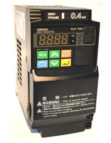
Схема открывания защитных крышек
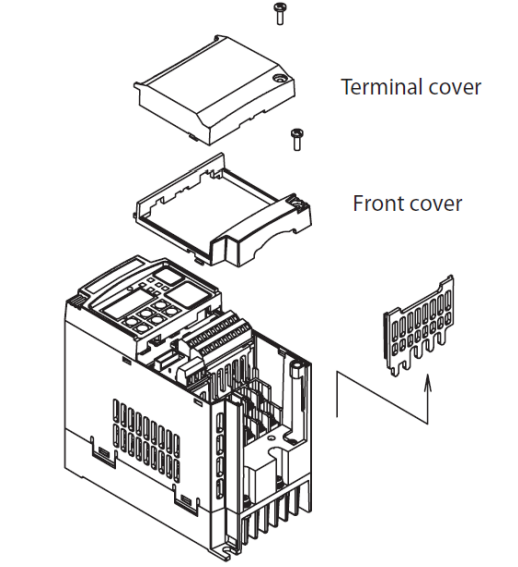
Особенности
- Пусковой крутящий момент до 200% на частотах близких к 0.5 Гц
- Двойная шкала мощности VT-переменный момент нагрузки с перегрузкой до 120% в течении 1мин и CT-постоянный момент нагрузки с перегрузкой до 150% в течении 1мин
- Управление двигателем с короткозамкнутым ротором или постоянными магнитами на роторе
- Безопасность в соответствии с ISO13849-1 Категория 3
- Встроенный программируемый логический контроллер ПЛК
- RS485 интерфейс для связи «Инвертор-Инвертор» или ModBus
- Режим позиционирования
Схема подключения входного сетевого питания и мотора
- Преобразователь частоты с однофазным напряжением питания (MX2-AB***-E) 220В.
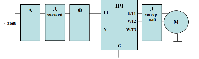
2. Преобразователь частоты с трехфазным напряжением питания (MX2-A4***-E) 380В.
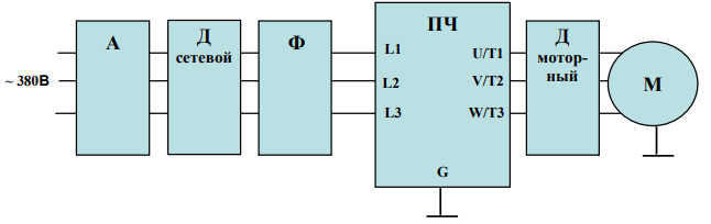
Клеммы цепи управления
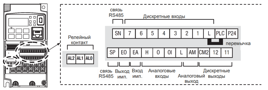
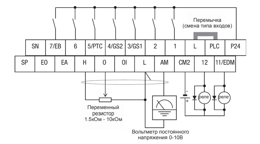
Спецификация клемм управления и сигнализации.
| Обозначение клеммы | Описание | Номинальная характеристика. Примечания |
| P24 | +24В для логических входов | +24В для питания логических входов. Максимальный ток 100мА. Не подключайте к питающей сети или заземлению. Не соединяйте с клеммой L. |
| PLC | Общая клемма логических входов | Заводская установка: истоковый тип (PLC соединена с L) клемма Р24 – опорное напряжение для входов 1-7. Для изменения типа входов нужно установить перемычку на клеммы PLC и P24, в этом случае клемма L – опорное напряжение для входов 1-7 |
| 1, 2, 3/GS1, 4/GS2, 5/PTC, 6, 7/EB |
Программируемые дискретные логические входы | Напряжение относительно клеммы PLC: Включение 18В и более, Выключение 3В и меньше, Максимальное допустимое 27В, Потребляемый ток входа 5мА (при 24В) |
| GS1 (3) | Вход безопасной остановки GS1 | Функционирование основано на ISO13849-1 |
| GS2 (4) | Вход безопасной остановки GS2 | Функционирование основано на ISO13849-1 |
| PTC (5) | Вход для термистора мотора | Подключите термистор мотора между клеммами PTC и L и установите функцию 19 в парасетре С005. Авария происходит если температура мотора возросла на столько, что сопротивление превышает 3кОм. |
| EB (7) | Вход В последовательности импульсов | Максимум 2 кГц. Относительно клеммы PLC. |
| EA | Вход А последовательности импульсов | Максимум 32 кГц. Относительно клеммы L. |
| L (верхний ряд) | Общая для дискретных входов | Общая для клемм 1 ÷ 7. Не заземлять. |
| 11/EDM | Дискретный логический выход, имеющий двойную функцию | Тип – открытый коллектор, максимальный ток: 50мА, Максимальное напряжение: 27В, относительно клеммы CM2. Функционирование EDM основано на ISO13849-1 |
| 12 | Дискретный логический выход | Тип – открытый коллектор, максимальный ток: 50мА, Максимальное напряжение: 27В, относительно клеммы CM2. |
| CM2 | Общая для дискретных выходов | 100мА, общий ток выходов 11 и 12 |
| АМ | Аналоговый выход напряжения | 0-10В пост., 1мА максимум |
| ЕО | Выход импульсный | 10В пост., 2мА макс, 32кГц макс |
| L (нижний ряд) | Общая для аналоговых сигналов | Проходит общий ток клемм OI, O и Н |
| OI | Аналоговый вход для токового сигнала | 4 – 19.6мА диапазон, 20мА номинал, Внутреннее сопротивление 250Ом |
| O | Аналоговый вход для сигнала напряжения | 0 – 9.8В диапазон, 10В номинал, Внутреннее сопротивление 10кОм |
| H | +10В для аналоговых входов | 10В номинал, 10мА макс. |
| SP, SN | Клеммы сетевого подключения | Для сети ModBus по RS485 |
| AL0 | Общий контакт реле аварийной сигнализации | 250 VAC 2.5 A (актив) мaкс. 250 VAC 0.2 A (индуктив) макс. 100 VAC 10 mA мин. 30 VDC 3.0 A (актив) max. 30 VDC 0.7 A (индуктив) макс. 5 VDC 100 mA мин. |
| AL1 | Контакт реле. Нормально открыт. |
250 VAC 2.5 A (актив) мaкс. 250 VAC 0.2 A (индуктив) макс. 100 VAC 10 mA мин. 30 VDC 3.0 A (актив) max. 30 VDC 0.7 A (индуктив) макс. 5 VDC 100 mA мин. |
| AL3 | Контакт реле. Нормально закрыт. |
250 VAC 2.5 A (актив) мaкс. 250 VAC 0.2 A (индуктив) макс. 100 VAC 10 mA мин. 30 VDC 3.0 A (актив) max. 30 VDC 0.7 A (индуктив) макс. 5 VDC 100 mA мин. |
Примечания:
- Обе клеммы L соединены между собой внутри инвертора.
- Рекомендуем использовать клемму L (верхний ряд) как общий для дискретных входов и L (нижний ряд) как общий для аналоговых входов/выходов.
Общая схема соединений
Cхема подключения питания, двигателя, дискретных и аналоговых входов и выходов.
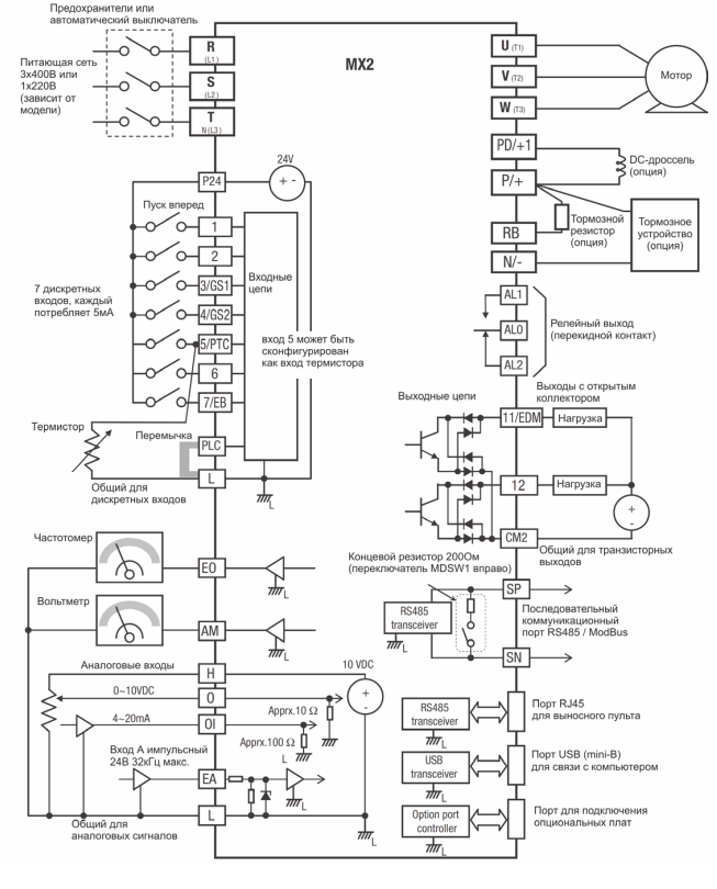
Элементы пульта оператора
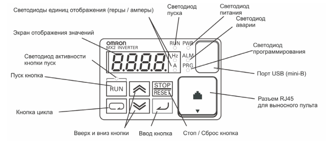
- Светодиод пуска – загорается при подаче команды на запуск двигателя во время начала вращения и отключается при остановке мотора.
- Светодиод программирования – загорается при готовности к изменению значений параметров и отключается в режиме контроля текущих параметров.
- Светодиод активности кнопки пуск – загорается при активированной кнопке и возможности с нее подать команду на запуск мотора.
- Кнопка пуска Run – при нажатии производится запуск двигателя (сначала должен светиться светодиод над кнопкой). Направление вращения двигателя можно задавать через функцию F004.
- Кнопка Stop/Reset – при нажатии производится остановка двигателя (при этом используется значение времени замедления), а также, происходит сброс возникающих ошибок.
- Экран отображения значений – 4-х разрядный, 7-ми сегментный индикатор для программирования и отображения параметров и текущих значений.
- Светодиоды: Hz, A – загораются при отображении на экране частоты или тока, соответственно.
- Светодиод Power – загорается при подаче питания на инвертор.
- Светодиод Alarm – загорается, когда инвертор в состоянии “Сбой”.
- Кнопка цикла – используется для входа в режим программирования, перемещения по группам параметров и функций.
- Кнопки вверх и вниз – используются для перемещения вверх/вниз по списку внутри 1 группы параметров и функций отображаемых на индикаторе и для изменения их значений.
- Кнопка ввода – используется для входа в отображаемый параметр или функцию, для выхода из нее с сохранением установленного значения в памяти EEPROM.
Порядок работы со списком параметров и функций
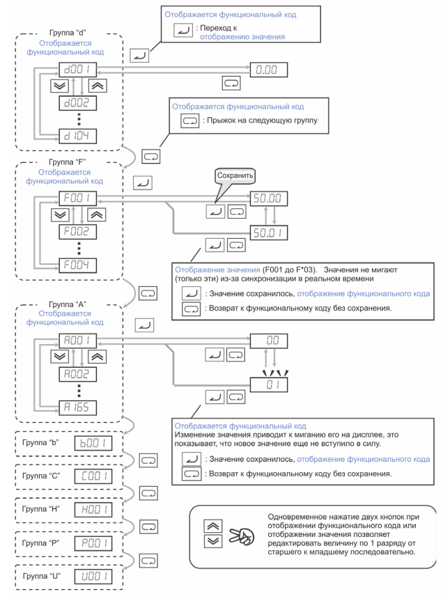
Коды ошибок
Преобразователи частоты серии МХ2 имеют защиту от перегрузки по току, от повышенного/ пониженного напряжения и много других. При срабатывании защиты отключается выход инвертора и остановка двигателя происходит в режиме свободного выбега. Перезагрузка частотного преобразователя и сброс ошибки производится нажатием кнопки STOP/RESET.
| Код ошибки | Наименование | Возможные причины сбоя |
| E01 | Защита от перегрузки по току при постоянной скорости | Замыкание на выходе инвертора Блокировка вала двигателя Слишком большая нагрузка Неправильно совершено подключение мотора Замечание: для серии SJ200 защита от перегрузки по току будет срабатывать при перегрузке 200% от номинального тока |
| E02 | Защита от перегрузки по току при замедлении | Замыкание на выходе инвертора Блокировка вала двигателя Слишком большая нагрузка Неправильно совершено подключение мотора Замечание: для серии SJ200 защита от перегрузки по току будет срабатывать при перегрузке 200% от номинального тока |
| E03 | Защита от перегрузки по току при разгоне | Замыкание на выходе инвертора Блокировка вала двигателя Слишком большая нагрузка Неправильно совершено подключение мотора Замечание: для серии SJ200 защита от перегрузки по току будет срабатывать при перегрузке 200% от номинального тока |
| E04 | Защита от перегрузки по току при других условиях | Установлен слишком большой тормозной момент (А054) Влияние электромагнитных помех на трансформатор тока |
| E05 | Защита от перегрузки | Электронное тепловое реле определило перегрев мотора |
| E06 | Защита от перегрузки тормозного резистора | Превышается время или коэффициент использования регенеративного торможения, слишком большой ток торможения |
| E07 | Защита от повышенного напряжения | Энергия, отдаваемая двигателем при торможении, вызывает увеличение напряжения в контуре постоянного тока выше порогового значения |
| E08 | Ошибка EEPROM | Влияние электромагнитных помех или высокой температуры на встроенную память EEPROM |
| E09 | Защита от пониженного напряжения | Пониженное напряжение в контуре постоянного тока может вызвать неправильное функционирование инвертора |
| E10 | Ошибка измерения тока | Выход из строя цепей измерения потребляемого мотором тока |
| E11 | Ошибка CPU | Сбои в работе микропроцессорного модуля CPU |
| E12 | Сбой во внешней цепи | Подан сигнал на дискретный вход с функцией [EXT] (сбой в работе внешнего устройства) |
| E13 | USP – предотвращение перезапуска при восстановлении питания | Когда на инвертор подаётся питание при наличии команды Пуск мотора происходит сбой с блокировкой возможность запуска пока не сброшен сбой, если активна функция USP |
| E14 | Защита от замыкания на землю | Замыкание на землю между выходом инвертора и корпусом мотора (заземлением) в момент теста питания (между подачей питания на ПЧ и пуском мотора). Данная функция обеспечивает защиту инвертора, но не людей. |
| E15 | Защита от повышенного напряжения на входе | Сетевое напряжение превышало допустимое значение в течение 100сек режима Стоп. |
| E21 | Тепловая защита | Внутренняя температура инвертора (силового модуля) превышает пороговое значение. |
| E22 | Ошибка связи с CPU | Ошибка связи между двумя процессорами |
| E25 | Авария основных цепей | Влияние помех или повреждение цепей основных элементов |
| E30 | Ошибка драйвера | Внутренняя ошибка в цепях защиты между CPU и драйвером из-за влияния помех или повреждения. |
| E35 | Термисторная защита | Происходит если термистор, подключенный к клеммам 5 (с функцией ТНМ) и L слишком сильно нагрелся |
| E36 | Ошибка тормоза | Происходит если в b120 установлен 01 и не получен сигнал подтверждения от тормоза после истечения времени b124. Или когда выходной ток не достигает значения b126 в течение времени b121 |
| E37 | Безопасный стоп | Подан сигнал безопасного стопа |
| E38 | Защита от перегрузки на маленькой скорости | Перегрузка во время работы мотора на очень маленькой скорости |
| E40 | Ошибка пульта оператора | Проблема связи между инвертором и клавиатурой пульта оператора |
| E41 | Ошибка связи сети ModBus | Если С076=00 и произошла проблема связи в сети ModBus |
| E43 | Некорректная инструкция в программе EzSQ | Программа сохраненная в памяти инвертора уничтожена, или терминал PRG был включен без программы загруженной в инвертор. |
| E44 | Ошибка счета в программе EzSQ | Подпрограммы, if-условия, или for-циклы вложены в более чем в восемь уровней |
| E45 | Ошибка инструкции в программе EzSQ | Инвертор обнаруживал команду, которая не может быть выполнена (взаимопротиворечие). |
| E50 – E59 | Пользовательские ошибки (0 – 9) в программе EzSQ | Ошибка пользователя, заложенная в программе EzSQ |
| E60 – E69 | Ошибки в подключенных опциональных платах | Детальные пояснения каждой из ошибок в инструкции к опциональной плате |
| E80 | Отключение энкодера | Если провода энкодера разъединены, обнаружена ошибка подключения, повреждение энкодера или выходной сигнал энкодера не поддерживается преобразователем |
| E81 | Превышение скорости | Скорость мотора выше значения А004хР026 |
| E82 | Ошибка диапазона позиционирования | Если текущая позиция превышает диапазон позиционирования P072-P073 |
Скачать полную документацию по настройке и программированию на Русском языке.
RU
ENG