-
Page 1
O P T I G O R E G U L A T O R – R E A D Y — S T E A D Y — G O Optigo OP5 Manual ©Copyright AB Regin, Sweden, 2007… -
Page 2
DISCLAIMER The information in this manual has been carefully checked and is believed to be correct. Regin however, makes no warranties as regards the contents of this manual and users are requested to report errors, discrepancies or ambiguities to Regin, so that corrections may be made in future editions. -
Page 3: Table Of Contents
Table of contents Chapter 1 About this manual ………………….4 Terms …………………………….4 More information …………………………..4 Chapter 2 Introduction to Optigo………………….5 Optigo controllers ……………………….5 Chapter 3 Technical data ……………………7 Chapter 4 Installation and wiring…………………..8 Installation…………………………8 Wiring …………………………..8 Supply voltage…………………………..8 Inputs and outputs ………………………….9 Chapter 5 Control modes……………………10 Control mode 1, Temperature control ……………………10 Control mode 2, CO…
-
Page 4: Chapter 1 About This Manual
Factory setting, the parameter value set on delivery More information • More information on OP5 can be found in: • Optigo controllers – Sales brochure for Optigo controllers • Optigo product instruction The information can be downloaded from the Regin website, www.regin.se.
-
Page 5: Chapter 2 Introduction To Optigo
Chapter 2 Introduction to Optigo Optigo controllers Optigo is a new series of pre-programmed, configurable controllers that can be set to handle everything from temperature control or humidity control to CO control or pressure control. OP 5 och OP 10 The Optigo series comprises two different types, OP5 and OP10.
-
Page 6
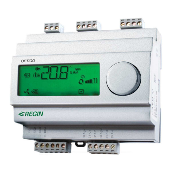
Optigo OP5 Optigo OP5 is a new pre-programmed, configurable controller. It has been designed with the main intention of replacing a number of Regin’s Aqualine controllers. All configuration and normal handling is done using the display and the knob on the front. -
Page 7: Chapter 3 Technical Data
External temperature sensors……….TG-R5/PT1000, TG-KH/PT1000 -sensor ……………….CO2RT, CO2RT-D, CO2DT Humidity sensor ………….HRT, HRT250, HDT3200, HDT2200 Pressure sensor …………. DMD, DTL-series, DTK-series, TTK-series The accessories are available from Regin. For more detailed information, see product sheets and instructions which are available at www.regin.se.
-
Page 8: Chapter 4 Installation And Wiring
Supply voltage 24 V AC ±15%, 50…60 Hz. 6 VA If the Optigo OP5 and active sensors and actuators connected to it share transformer, it is essential that the same transformer-pole is used as reference for all the equipment. Failure to…
-
Page 9: Inputs And Outputs
Analogue outputs must refer to a A terminal or directly to G0. If the Optigo OP5 and active sensors and actuators connected to it share transformer, it is essential that the same transformer-pole is used as reference for all the equipment. Failure to…
-
Page 10: Chapter 5 Control Modes
Chapter 5 Control modes Optigo can be configured to any one of the following control modes. 1. Temperature control. The temperature at the sensor is kept at the setpoint value by controlling the output signals on AO1 and AO2. A single PI control loop is used. 2.
-
Page 11
4. Heating Heating 5. Cooling / Cooling 6. Heating / Damper 7. Cooling / Damper 8. Change-over/ (Seasonal change-over between heating and cooling) DI1, Start signal Normal control will only be activated when this input is activated, closed. When the start signal is deactivated the controller will set the outputs to 0. -
Page 12: Control Mode 2, Co Control
Control mode 2, CO control The output signal will increase when the CO -value rises above the setpoint value. The CO -sensor must have a 0…10 V DC output for example: CO2RT, CO2RT-D Room sensors CO2DT Duct sensor The transmitter range cannot exceed 5000 ppm at 10 V DC output. DI1, Start signal Normal control will only be activated when this input is activated, closed.
-
Page 13: Control Mode 3, Humidity Control
Control mode 3, Humidity control RH max Humidification and dehumidification can be used simultaneously. A neutral zone can be set between humidification and dehumidification. The humidity transmitter must have an output signal of 0…10 V DC, for example: HRT, HRT250 or HRT350 Room humidity transmitters HDT2200 or HDT3200 Duct transmitters…
-
Page 14: Control Mode 4, Pressure Control
Control mode 4, Pressure control Pump f f / f f / The output signal will increase when the pressure signal falls below the setpoint value. The pressure transmitter must have an output signal of 0…10 V DC, for example: DTL-series DTK-series TTK-series…
-
Page 15: Control Mode 5, Pressure Control With Outdoor Temperature Compensation Of The Pressure Setpoint
Control mode 5, Pressure control with outdoor temperature compensation of the pressure setpoint. f f / The output signal will increase when the pressure signal falls below the setpoint value. The setpoint value follows a settable pressure-to-outdoor temperature relation. The pressure transmitter must have an output signal of 0…10 V DC, for example: DTL-series DTK-series TTK-series…
-
Page 16: Chapter 6 Display And Encoder
Chapter 6 Display and encoder All setting and configuration is done using the display and encoder. The menu information on the display is organised in a tree fashion. Using the encoder you can move between menus, set values etc. In any of the configuration menus, a press on the encoder will activate change mode. You can then rotate the encoder button to move between choices or set values.
-
Page 17: The 10-Second Level
The 10-second level This level is reached from the Base Display by depressing and holding the encoder button for 10 seconds. The 10-second level holds all the configuration menus. See chapter 8 Configuration. Note: The controller must displat the Base Display when pressing the encoder knob to reach the 10-second level.
-
Page 18: Chapter 7 Setpoint
Chapter 7 Setpoint The setpoint menu is normally accessed from the Base Display by a klicking on the encoder knob. If you wish to change the displayed value, klick on the knob again and the change indicators will start to flash to show that you are now in change mode. Twist the knob, clockwise to increase the value, counter-clockwise to decrease.
-
Page 19: Chapter 8 Configuration
Chapter 8 Configuration All the configuration menus lie in the 10-seconds level. This level is accessed from the Base Display by pressing and holding the encoder button for 10 seconds. There are numerous configuration menus covering all available options and combinations. In some cases, making a certain choice in one menu will mean that you will only see certain other menus.
-
Page 20: Menus X.2 Neutral Zone (Control Mode 1 And 3)
For each alternative the number representing it is shown along with a graphic symbolisation of the output signals and also a symbol next to the bar-graph for each output. Output signals, graphical Example, Menu 1.1 Control mode 1 menu 1 Temperature control with AO1 Heating output alternative 3…
-
Page 21: Menus X.4 I-Time
Menus X.4 I-time Here you set the Integration time (Reset time). If the I-time is set to 0 the integration function is disabled and the controller will act as a P-controller. Menu 1.5 Damper minimum position (Control mode 1 only) If you in menu 1.1 have configured output AO2 to be a damper, alternative 6 or 7, you can set a minimum value to the damper signal.
-
Page 22: Menus X.9 I/O
Menus X.9 I/O After the last configuration menu there is a menu where you can look at the actual values of all the inputs and outputs. This menu can also be accessed directly from the Base Display by twisting the encoder knob counter clockwise and then pressing. See chapter 6. Menu OK Last of the configuration level menus is the OK-menu.
-
Page 23: Chapter 9 Index
Chapter 9 Index I-time ……………….21 10 second level…………..17 LVD………………7 Analogue inputs …………..9 Analogue outputs …………..9 Menu Configuration …………..19 I/O …………….16, 22 OK……………….22 Setpoint …………..16, 18 Basic level …………….16 Mounting …………….5 Change-over ……………. 11 Reset time …………..See I-time Configuration …………..
-
Page 24
+ 46 (0)31-720 02 50 Websida: www.regin.se Försäljningskontor Frankrike Försäljningskontor Singapore Försäljningskontor Hong Kong Regin Control SARL Regin Controls Asia Pacific Pte Ltd Regin Controls Hong Kong Limited 5 Rue Regnault 66 Tannery Lane, 2901 EW International Tower FR-93500 Pantin, France…
Контакты
г. Москва, 1-й Нагатинский проезд, д. 2
Телефон: +7 (499) 406-00-60
PGlmcmFtZSBzcmM9Imh0dHBzOi8vd3d3Lmdvb2dsZS5jb20vbWFwcy9lbWJlZD9wYj0hMW0xOCExbTEyITFtMyExZDIyNDkuMzg3NTA2MTMwOTE2ITJkMzcuNjMwODk3MjE1NjY5MzMhM2Q1NS42ODIyNTAzODA1MzQ1MDUhMm0zITFmMCEyZjAhM2YwITNtMiExaTEwMjQhMmk3NjghNGYxMy4xITNtMyExbTIhMXMweDQxNGFiMzU2NzFjNWJhNmYlM0EweDMxZjc1Y2RiZGU0YzI4OWMhMnpNUzNRdVNEUW5kQ3cwTFBRc05HQzBMalF2ZEdCMExyUXVOQzVJTkNfMFlBdDBMUXNJRElzSU5DYzBMN1JnZEM2MExMUXNDd2dNVEUzTVRBMSE1ZTAhM20yITFzcnUhMnNydSE0djE0OTk4MjAxOTU4NjEiIHdpZHRoPSI2MDAiIGhlaWdodD0iNDUwIiBmcmFtZWJvcmRlcj0iMCIgc3R5bGU9ImJvcmRlcjowIiBhbGxvd2Z1bGxzY3JlZW4+PC9pZnJhbWU+
Спасибо. Мы свяжемся с вами как можно скорее.
- Manuals
- Brands
- Regin Manuals
- Controller
- OPTIGO OP5
- Manual
-
Contents
-
Table of Contents
-
Bookmarks
Quick Links
O P T I G O
R E G U L A T O R
–
R E A D Y — S T E A D Y — G O
Optigo OP5 Manual
©Copyright AB Regin, Sweden, 2007
Related Manuals for Regin Optigo OP5
Summary of Contents for Regin Optigo OP5
-
Page 1
O P T I G O R E G U L A T O R – R E A D Y — S T E A D Y — G O Optigo OP5 Manual ©Copyright AB Regin, Sweden, 2007… -
Page 2
DISCLAIMER The information in this manual has been carefully checked and is believed to be correct. Regin however, makes no warranties as regards the contents of this manual and users are requested to report errors, discrepancies or ambiguities to Regin, so that corrections may be made in future editions. -
Page 3: Table Of Contents
Table of contents Chapter 1 About this manual ………………….4 Terms …………………………….4 More information …………………………..4 Chapter 2 Introduction to Optigo………………….5 Optigo controllers ……………………….5 Chapter 3 Technical data ……………………7 Chapter 4 Installation and wiring…………………..8 Installation…………………………8 Wiring …………………………..8 Supply voltage…………………………..8 Inputs and outputs ………………………….9 Chapter 5 Control modes……………………10 Control mode 1, Temperature control ……………………10 Control mode 2, CO…
-
Page 4: Chapter 1 About This Manual
Factory setting, the parameter value set on delivery More information • More information on OP5 can be found in: • Optigo controllers – Sales brochure for Optigo controllers • Optigo product instruction The information can be downloaded from the Regin website, www.regin.se.
-
Page 5: Chapter 2 Introduction To Optigo
Chapter 2 Introduction to Optigo Optigo controllers Optigo is a new series of pre-programmed, configurable controllers that can be set to handle everything from temperature control or humidity control to CO control or pressure control. OP 5 och OP 10 The Optigo series comprises two different types, OP5 and OP10.
-
Page 6
Optigo OP5 Optigo OP5 is a new pre-programmed, configurable controller. It has been designed with the main intention of replacing a number of Regin’s Aqualine controllers. All configuration and normal handling is done using the display and the knob on the front. -
Page 7: Chapter 3 Technical Data
External temperature sensors……….TG-R5/PT1000, TG-KH/PT1000 -sensor ……………….CO2RT, CO2RT-D, CO2DT Humidity sensor ………….HRT, HRT250, HDT3200, HDT2200 Pressure sensor …………. DMD, DTL-series, DTK-series, TTK-series The accessories are available from Regin. For more detailed information, see product sheets and instructions which are available at www.regin.se.
-
Page 8: Chapter 4 Installation And Wiring
Supply voltage 24 V AC ±15%, 50…60 Hz. 6 VA If the Optigo OP5 and active sensors and actuators connected to it share transformer, it is essential that the same transformer-pole is used as reference for all the equipment. Failure to…
-
Page 9: Inputs And Outputs
Analogue outputs must refer to a A terminal or directly to G0. If the Optigo OP5 and active sensors and actuators connected to it share transformer, it is essential that the same transformer-pole is used as reference for all the equipment. Failure to…
-
Page 10: Chapter 5 Control Modes
Chapter 5 Control modes Optigo can be configured to any one of the following control modes. 1. Temperature control. The temperature at the sensor is kept at the setpoint value by controlling the output signals on AO1 and AO2. A single PI control loop is used. 2.
-
Page 11
4. Heating Heating 5. Cooling / Cooling 6. Heating / Damper 7. Cooling / Damper 8. Change-over/ (Seasonal change-over between heating and cooling) DI1, Start signal Normal control will only be activated when this input is activated, closed. When the start signal is deactivated the controller will set the outputs to 0. -
Page 12: Control Mode 2, Co Control
Control mode 2, CO control The output signal will increase when the CO -value rises above the setpoint value. The CO -sensor must have a 0…10 V DC output for example: CO2RT, CO2RT-D Room sensors CO2DT Duct sensor The transmitter range cannot exceed 5000 ppm at 10 V DC output. DI1, Start signal Normal control will only be activated when this input is activated, closed.
-
Page 13: Control Mode 3, Humidity Control
Control mode 3, Humidity control RH max Humidification and dehumidification can be used simultaneously. A neutral zone can be set between humidification and dehumidification. The humidity transmitter must have an output signal of 0…10 V DC, for example: HRT, HRT250 or HRT350 Room humidity transmitters HDT2200 or HDT3200 Duct transmitters…
-
Page 14: Control Mode 4, Pressure Control
Control mode 4, Pressure control Pump f f / f f / The output signal will increase when the pressure signal falls below the setpoint value. The pressure transmitter must have an output signal of 0…10 V DC, for example: DTL-series DTK-series TTK-series…
-
Page 15: Control Mode 5, Pressure Control With Outdoor Temperature Compensation Of The Pressure Setpoint
Control mode 5, Pressure control with outdoor temperature compensation of the pressure setpoint. f f / The output signal will increase when the pressure signal falls below the setpoint value. The setpoint value follows a settable pressure-to-outdoor temperature relation. The pressure transmitter must have an output signal of 0…10 V DC, for example: DTL-series DTK-series TTK-series…
-
Page 16: Chapter 6 Display And Encoder
Chapter 6 Display and encoder All setting and configuration is done using the display and encoder. The menu information on the display is organised in a tree fashion. Using the encoder you can move between menus, set values etc. In any of the configuration menus, a press on the encoder will activate change mode. You can then rotate the encoder button to move between choices or set values.
-
Page 17: The 10-Second Level
The 10-second level This level is reached from the Base Display by depressing and holding the encoder button for 10 seconds. The 10-second level holds all the configuration menus. See chapter 8 Configuration. Note: The controller must displat the Base Display when pressing the encoder knob to reach the 10-second level.
-
Page 18: Chapter 7 Setpoint
Chapter 7 Setpoint The setpoint menu is normally accessed from the Base Display by a klicking on the encoder knob. If you wish to change the displayed value, klick on the knob again and the change indicators will start to flash to show that you are now in change mode. Twist the knob, clockwise to increase the value, counter-clockwise to decrease.
-
Page 19: Chapter 8 Configuration
Chapter 8 Configuration All the configuration menus lie in the 10-seconds level. This level is accessed from the Base Display by pressing and holding the encoder button for 10 seconds. There are numerous configuration menus covering all available options and combinations. In some cases, making a certain choice in one menu will mean that you will only see certain other menus.
-
Page 20: Menus X.2 Neutral Zone (Control Mode 1 And 3)
For each alternative the number representing it is shown along with a graphic symbolisation of the output signals and also a symbol next to the bar-graph for each output. Output signals, graphical Example, Menu 1.1 Control mode 1 menu 1 Temperature control with AO1 Heating output alternative 3…
-
Page 21: Menus X.4 I-Time
Menus X.4 I-time Here you set the Integration time (Reset time). If the I-time is set to 0 the integration function is disabled and the controller will act as a P-controller. Menu 1.5 Damper minimum position (Control mode 1 only) If you in menu 1.1 have configured output AO2 to be a damper, alternative 6 or 7, you can set a minimum value to the damper signal.
-
Page 22: Menus X.9 I/O
Menus X.9 I/O After the last configuration menu there is a menu where you can look at the actual values of all the inputs and outputs. This menu can also be accessed directly from the Base Display by twisting the encoder knob counter clockwise and then pressing. See chapter 6. Menu OK Last of the configuration level menus is the OK-menu.
-
Page 23: Chapter 9 Index
Chapter 9 Index I-time ……………….21 10 second level…………..17 LVD………………7 Analogue inputs …………..9 Analogue outputs …………..9 Menu Configuration …………..19 I/O …………….16, 22 OK……………….22 Setpoint …………..16, 18 Basic level …………….16 Mounting …………….5 Change-over ……………. 11 Reset time …………..See I-time Configuration …………..
-
Page 24
+ 46 (0)31-720 02 50 Websida: www.regin.se Försäljningskontor Frankrike Försäljningskontor Singapore Försäljningskontor Hong Kong Regin Control SARL Regin Controls Asia Pacific Pte Ltd Regin Controls Hong Kong Limited 5 Rue Regnault 66 Tannery Lane, 2901 EW International Tower FR-93500 Pantin, France…

-
Ответить
-
Создать новую тему
Рекомендуемые сообщения
")
-
- Поделиться
нуждаюсь в помощи по настройки контролера Optigo OP10
- Цитата
Ссылка на комментарий
Поделиться на другие сайты

")
-
- Поделиться
Опиши что ты хочешь сделать, что ты сделал, что не получилось и в чём конкретно нужна помощь.
Учись задавать вопросы.
- Цитата
Ссылка на комментарий
Поделиться на другие сайты
- Автор
-
- Поделиться
можно ли в первом режиме контролера «регулировка температуры природного воздуха » регулировать автоматически заслонку на заборе уличного воздуха?
- Цитата
Ссылка на комментарий
Поделиться на другие сайты
Вебинар «Мощные модульные системы питания MEAN WELL 3+N. Новинки и хиты» (22.06.2023)
Приглашаем 22 июня на вебинар, посвященный подходу компании MEAN WELL к созданию мощных управляемых систем низковольтного и высоковольтного питания и зарядных установок для промышленного, технологического, телекоммуникационного, медицинского, радиопередающего и другого оборудования, а также для систем альтернативной энергетики.
На вебинаре мы рассмотрим новинки и серийную продукцию в концепции «3+N», расскажем об этой концепции и о том, как создать из готовых модулей систему питания мощностью до 360 кВт с напряжением до 380…400 В (постоянного тока). Будут представлены ИП с рециркуляцией энергии для тестового оборудования и модули управления питанием. Подробнее>>

")
-
- Поделиться
Уж очень твой Optigo специфичный. Посмотри, может в инструкции что найдешь?
Optigo_10.pdf
- Цитата
Ссылка на комментарий
Поделиться на другие сайты

- Автор
-
- Поделиться
В том и дело что такая иструкция есть. Дело в том что я могу настроить только первый режим «настройка температуры природного воздуха» а вот заслонка на забор приточного воздуха с улицы открывается на все 100% , а так как на улице холодно холодный воздух замораживает датчик и вся система встает и выводит ошибку. Мне надо добиться того чтобы автоматически заслонка закрывалась при нижних темпиратурах приточного воздуха.
- Цитата
Ссылка на комментарий
Поделиться на другие сайты

")
-
- Поделиться
Nikita, в приборе реализовано ПИ-управление (пропорционально-интегральный регулятор, стр.12, п.1, п.2). От его настроечных параметров полностью зависит поведение регулятора.
И почему Вы не можете использовать другие режимы регулирования?
Также нужно знать, как реализована вся система подачи и поддержания температуры приточного воздуха. И для чего все это нужно.
- Цитата
Ссылка на комментарий
Поделиться на другие сайты

- Автор
-
- Поделиться
Я знаю что такое пид регулятор проблема в том что регулировать заслонку доступно для второго и третьего режима может я что то не понял из иструкции по настройки. при настройки 2 или 3 режима выдает ошибку «обрыв датчика».
- Цитата
Ссылка на комментарий
Поделиться на другие сайты
-
- Поделиться
Nikita, не совсем понятна схема управления, примененная у Вас. Вернее, совсем нет ее.
Что именно Вы регулируете? Есть ли нагреватели, как подключен привод заслонки?..
В режимах 2 и 3 нужно применять 2 датчика температуры. У Вас сколько, где установлены и к каким входам подключены?
Опишите для начала полностью свою систему, там видно будет.
- Цитата
Ссылка на комментарий
Поделиться на другие сайты
- Автор
-
- Поделиться
Ссылка на комментарий
Поделиться на другие сайты
-
- Поделиться
Ушел, что ли? Как понимать сей знак относительно форума?
- Цитата
Ссылка на комментарий
Поделиться на другие сайты
- 1 год спустя…

Гость Александр
-
- Поделиться
доброе время суток! мой вопрос таков: как отключитьустранить ошибку AL1.
- Цитата
Ссылка на комментарий
Поделиться на другие сайты
-
- Поделиться
Почитать инструкцию и сделать выводы.
Отсюда не видно, что и куда там у Вас подключено и какая реальная температура.
- Цитата
Ссылка на комментарий
Поделиться на другие сайты
- 8 месяцев спустя…
Гость Андрей
-
- Поделиться
Добрый день. Прошу помощи специалистов. Использую контроллер Optigo OP-10 для управления температурой воздуха в системе вентиляции с водяным калорифером с функцией защиты от замерзания. Выходной сигнал на привод- трехпозиционный. Режим работы- обогрев. В инструкции сказано (описание меню Х.7), что при угрозе замораживания выходной сигнал увеличивается до 100 процентов либо на выход АО1, либо на выход АО2 (сам выбираешь куда). Но при трехпозиционном регулировании эти выходы не задействуются. Как же тогда реализуется защита от замерзания?
- Цитата
Ссылка на комментарий
Поделиться на другие сайты
- 2 недели спустя…
Гость Юрий
-
- Поделиться
Андрею.
Уровень сигнала можете наблюдать на главном экране или по AO1, а воздействие будет на выходы DO1(открытие) и DO2(закрытие).
Обратите внимание, если вы используете датчик температуры обратной воды на UI1, то при опускании температуры обр. воды ниже 25’C UI1 покажет 0’С и остановит систему(будет AL1).
При этом система начнет регулировать температуру обраной воды. Сначала откроет клапан на 100% пока не достигнет 25’C? а после этого перейдет в режим поддержания темп. обратной воды 7-12’С (100-0% открытия клапана соответственно).
Юрий.
- Цитата
Ссылка на комментарий
Поделиться на другие сайты
- 1 месяц спустя…
Гость Гость
-
- Поделиться
В продолжении хочу поделиться опытом.
Установил в паралель датчику температуры обратной воды на UI1 резистор 11кОм через NC-контакт пускателя.
В результате — при останове ВС температура обратного теплоносителя определяется как на 30’С ниже.
Пример: во время работы t обр. воды была 42’С. При останове индицирует уже 12’С(хотя реальная так и осталась 42).
Контроллер при останове поддерживает t обр. воды 7-12 — по индикатору, а в реале 37-42.
- Цитата
Ссылка на комментарий
Поделиться на другие сайты
- 8 месяцев спустя…
Гость Дмитрий
-
- Поделиться
Добрый день. Люди добрые, подскажите. На OP10 построена приточка. Нажимаю запуск, через 10 сек отключается пускатель тенов заслонки(судя по описанию оставленному монтажниками), секунд через 30 отключается вентилятор. выпадает в аварию AL3. Что может быть, куда смотреть? Инструкцию читал, разобраться не могу ![]()
- Цитата
Ссылка на комментарий
Поделиться на другие сайты
Гость Дмитрий
-
- Поделиться
Причем дня 4 назад включал, он проработал 2 дня. А сейчас опять в аварию выпадает.
- Цитата
Ссылка на комментарий
Поделиться на другие сайты
-
- Поделиться
Это — контроллер. Какая программа в нем зашита — то он и выполняет.
Читайте мануал. На стр. 25 описана эта ошибка.
- Цитата
Ссылка на комментарий
Поделиться на другие сайты
-
- Поделиться
Приветствую. Подскажите кто сталкивался. Валялся в закромах OP10. Собрал на нем щит управления приточкой. Датчики температуры применил Овен, ДТС3225-PT1000.B2 на обратку и ДТС3015-PT1000.B2.200 в канал. Теплоносителя пока нет, гонял без нагрева. При температуре на улице +2, канальный датчик показывает +11. В документации пункта коррекции показаний не наблюдаю. Что делать?
- Цитата
Ссылка на комментарий
Поделиться на другие сайты
-
- Поделиться
1. Проверить правильность подключения.
2. Проверить конфигурацию прибора (настройки).
3. Подключить вместо датчика температуры магазин сопротивлений и проверить показания прибора.
4. Удостовериться в точности параметров датчиков температуры.
Какое расстояние от датчика до прибора?
- Цитата
Ссылка на комментарий
Поделиться на другие сайты
- 4 года спустя…
Гость Евгений
-
- Поделиться
Добрый день. Объясните пожалуйста по пи регуляции, у меня Optigo op10:
Sp (уставка) — т.е. температура которая мне необходима
Р (зона пропорциональности) — т.е. если установлен параметр 1, при отклоненнии на 1 градус система будет запускаться (работать)
I время в течении которого необходимо изменять параметр, например, частотника
Все ли верно я понимаю?
Установки: sp-15, p-1, i-16, в помещении 23; система даже аврии по перегреву не выдает. Режим работы от 1датчика, охлаждение.
- Цитата
Ссылка на комментарий
Поделиться на другие сайты
Присоединяйтесь к обсуждению
Вы можете написать сейчас и зарегистрироваться позже.
Если у вас есть аккаунт, авторизуйтесь, чтобы опубликовать от имени своего аккаунта.
Примечание: Ваш пост будет проверен модератором, прежде чем станет видимым.
-
Последние посетители
0 пользователей онлайн
- Ни одного зарегистрированного пользователя не просматривает данную страницу
-
Сообщения
-

Автор
la5fn · Опубликовано 30 минут назад
Попробуй промоделить пару, а потом одиночный BD682G при тех же условиях… Лично мне не нравится как там ведут себя «толстые» транзеля. А более шустрые помельче — в самый раз. Обьясни сам себе, отчего падают искажения в паре? Мне ненужно. Кроме того режим у них тут погорячее кетайских клонов, а в целом мне нравится когда недушно. Ты разумеется можешь делать как тебя научили, я ж не настаиваю))
-
Автор
Alex_63 · Опубликовано 1 час назад
Транзистору BD682G, максимальной мощностью сорок ватт, очень скучно и одиноко работать в классе А при рабочей мощности рассеяния почти в 10 раз меньше. Вот у пары транзисторов то запас ещё больше (веселее) будет. Запас по току ничуть не меньше, т.к. мах.ток коллектора 4 А.
Моделирование показало, что в усилителе напряжения один 2SA1837 или 2SA1930, вместо пары BD682G ничуть не хуже, в том числе и по искажениям.
-
Автор
Dr. West · Опубликовано 1 час назад
Проблема в «ремонтнике». Надо его поменять. И найти человека, который умеет делать осознанную диагностику неисправности и ремонт, а не ставить перемычки.
-
Автор
Yurkin2015 · Опубликовано 3 часа назад
Станет ещё хуже, т.к. выходное напряжение стабилизируется относительно земли, которая осталась внутри «за шунтом». Если передвинуть делитель, то при увеличении тока выходное напряжение будет падать потому, что к делителю снизу добавится напряжение шунта, и стабилизатор будет компенсировать эту добавку. Также минусовой выход поднимется на величину падения напряжения на шунте. Хором получится удвоенное ухудшение выхода при увеличении тока.
Надо и делитель и опорное напряжение +2.0В тоже передвинуть, т.е. двигаем всю землю направо от шунта, оставляем слева только токовый вход R3.
Остаётся неясным, будет ли работать у 494 усилитель ошибки при входном напряжении в районе 0 В плюс-минус децл в канале тока.
-
Автор
Blackbird · Опубликовано 3 часа назад
Не знаю можно ли тут такое писать, но этот блочек же копейки стоит, зачем его чинить?
Обычно там на входе эти пленочные конденсаторы дохнут, если не оно то все подряд менять вам не целесообразно наверн. Хотя дома я поменял на советские и уже 10 лет работает.
Что касается не того режима — ну поменяйте местами провода на тот что надо, как по мне то как раз удобно если настроить последовательность, даже пульт не нужен обычно
-
Автор
petserg888 · Опубликовано 4 часа назад
Tpa3255 на Алике меньше 10 баксов одна, а проще готовый взять за 2000р. и наслаждаться «великим» D
https://aliexpress.ru/item/1005005008916111.html?sku_id=12000031328626005&spm=a2g2w.productlist.search_results.10.1f8935e4hMTRxy
-
Автор
petserg888 · Опубликовано 4 часа назад
Человек счастлив и это здорово, зачем его гнобить. Это для Вас важен THD IHD выходное сопротивление и ТД. Он нашел свое, а мы все ищем.
-