
- Page 1
FS-1040 FS-1060DN SERVICE MANUAL Published in March 2012 842M3110 2M3SM060 First Edition… - Page 2
Notation of products in the manual For the purpose of this service manual, products are identified by print speed at A4 modes. FS-1040: 20/21 ppm model FS-1060DN: 25/26 ppm model… - Page 3
Revision history Revision Date Replaced pages Remarks… - Page 4
This page is intentionally left blank. -
Page 5: Safety Precautions
Safety precautions This booklet provides safety warnings and precautions for our service personnel to ensure the safety of their customers, their machines as well as themselves during maintenance activities. Service personnel are advised to read this booklet carefully to familiarize themselves with the warnings and precautions described here before engaging in maintenance activities.
- Page 6
Safety warnings and precautions Various symbols are used to protect our service personnel and customers from physical danger and to prevent damage to their property. These symbols are described below: DANGER: High risk of serious bodily injury or death may result from insufficient attention to or incorrect compliance with warning messages using this symbol. -
Page 7: Installation Precautions
1. Installation Precautions WARNING • Do not use a power supply with a voltage other than that specified. Avoid multiple connections to one outlet: they may cause fire or electric shock. When using an extension cable, always check that it is adequate for the rated current…………………. •…
-
Page 8: Specifications 1
2. Precautions for Maintenance WARNING • Always remove the power plug from the wall outlet before starting machine disassembly….• Always follow the procedures for maintenance described in the service manual and other related brochures……………………….• Under no circumstances attempt to bypass or disable safety features including safety mechanisms and protective circuits.
- Page 9
• Do not remove the ozone filter, if any, from the copier except for routine replacement……. • Do not pull on the AC power cord or connector wires on high-voltage components when removing them; always hold the plug itself………………….•… - Page 10
This page is intentionally left blank. -
Page 11: Table Of Contents
2M2/2M3 CONTENTS 1-1 Specifications 1-1-1 Specifications ……………………1-1-1 1-1-2 Parts names …………………….. 1-1-3 (1) Machine ……………………..1-1-3 (2) Operation panel …………………… 1-1-4 1-1-3 Machine cross section ………………….1-1-5 (1) 20/21 ppm Model………………….1-1-5 (2) 25/26 ppm Model………………….1-1-6 1-2 Installation 1-2-1 Installation environment………………….
-
Page 12: Assembly And Disassembly
(1) Precautions……………………1-5-1 (2) Drum……………………..1-5-1 (3) Toner ……………………..1-5-1 (4) How to tell a genuine Kyocera Mita toner container …………1-5-2 1-5-2 Outer covers …………………….. 1-5-3 (1) Detaching and refitting the top cover…………….1-5-3 (2) Detaching and refitting the Right cover …………….1-5-4 (3) Detaching and refitting the Left cover…………….
- Page 13
2M2/2M3 2-4 Appendixes 2-4-1 Maintenance kits……………………2-4-1 (1) Maintenance kits………………….. 2-4-1 2-4-2 Procedure for replacing Maintenance kit …………….2-4-2 (1) Preparation ……………………2-4-2 (2) Detaching the Drum unit………………..2-4-4 (3) Detaching the developer unit……………….. 2-4-4 (4) Detaching the toner disposal box ………………2-4-5 (5) Detaching and refitting the paper feed pulley and lower paper feed guide …… - Page 14
2M2/2M3 This page is intentionally left blank. -
Page 15: Specifications
2M2/2M3 1-1 Specifications 1-1-1 Specifications Machine Specifications Item 20/21 ppm 25/26 ppm Type Desktop Printing method Electrophotography, laser scan Cassette 60 to 220 g/m Paper weight Manual feed 60 to 220 g/m tray* Cassette/ Plain, Preprinted, Labels, Bond, Recycled, Vellum, Rough, Letterhead, Paper type Manual feed Color, Prepunched, Envelope, Cardstock, Thick paper, High Quality, Cus-…
- Page 16
2M2/2M3 Specifications Item 20/21 ppm 25/26 ppm Standard 150 sheets (80 g/m paper Output tray capacity Special 1 sheets paper Continuous copying 1 to 999 sheets Photoconductor OPC drum (drum diameter 24 mm) Image write system Semiconductor laser (1 beam) Charging system Charger roller Mono component dry developing method… -
Page 17: Parts Names
2M2/2M3 1-1-2 Parts names (1) Machine 9 10 Figure 1-1-1 1. Top tray 9. Cassette 2. Paper stopper 10. Paper width guides 3. Operation panel 11. Paper length guide 4. Power switch 12. Fuser top cover 5. Front cover 13. Rear cover 6.
-
Page 18: Operation Panel
2M2/2M3 (2) Operation panel Figure 1-1-2 1. Processing indicator 2. Attention indicator 3. Go key 4. Cancel key 5. Quiet Mode key 1-1-4…
-
Page 19: Machine Cross Section
2M2/2M3 1-1-3 Machine cross section (1) 20/21 ppm Model Light path Paper path Figure 1-1-3 1. Cassette 7. Drum unit 2. Paper feed/conveying section 8. Transfer/separation section 3. Toner container 9. Laser scanner unit 4. Developing unit 10. Fuser section 5.
-
Page 20: 25/26 Ppm Model
2M2/2M3 (2) 25/26 ppm Model Light path Paper path Figure 1-1-4 1. Cassette 8. Drum unit 2. Paper feed/conveying section 9. Transfer/separation section 3. Manual feed tray 10. Laser scanner unit 4. Toner container 11. Fuser section 5. Developing unit 12.
-
Page 21: Installation Environment
2M2/2M3 1-2 Installation 1-2-1 Installation environment 1. Temperature: 10 to 32.5°C/50 to 90.5°F 2. Humidity: 15 to 80% RH 3. Power supply: 120 V AC, 5.4 A 220 — 240 V AC, 2.8 A 4. Power source frequency: 50 Hz ± 2%/60 Hz ± 2% 5.
-
Page 22: Unpacking And Installation
2M2/2M3 1-2-2 Unpacking and installation (1) Installation procedure Start Unpacking Taking out the machine Removing the tapes Installing the cassette cover Loading paper (cassette) Installing the toner container Connect the USB cable Connect the Network cable (25/26 ppm model) Connect the power cord Installing the toner Make test printing Installing the printer driver…
- Page 23
2M2/2M3 Unpacking Figure 1-2-3 1. Machine 9. Cassette cover 2. Outer case 10. Power cord 3. Bottom left pad 11. Toner container 12. DVD 4. Bottom right pad 5. Machine cover 13. Operation guide 6. Top left pad 14. Quick installation guide 7. - Page 24
2M2/2M3 Removing the tapes 1. Remove tape. Tapes Figure 1-2-4 Tape 2. Remove two tapes. Tape Figure 1-2-5 1-2-4… - Page 25
2M2/2M3 Installing the cassette cover 1. Attach the cassette cover. Guide MF base Attach the cassette cover so that its right and left-side pins and the boss on the machine frame mate with each other. *: If performing installation in a 25 ppm model, install the cassette cover so that its guide at the top is positioned above the MF base. - Page 26
2M2/2M3 3. Adjust the paper length guide to the paper size required. Paper length guide Figure 1-2-9 4. Load the paper all the way in the cas- sette until the paper touches the far inner side. *: Ensure the side to be printed is facing up and the paper is not folded, curled, or damaged. - Page 27
2M2/2M3 *: Load an amount of paper that fits under the tabs on the width guides. *: Ensure that the loaded paper does not exceed the level indicated. Tabs Exceed the level indicated Figure 1-2-12 5. Close the cassette cover. Figure 1-2-13 1-2-7… - Page 28
2M2/2M3 Installing the toner containers 1. Open the front cover. Front cover Figure 1-2-14 2. Shake the toner container at least 10 times as shown in the figure in order to distribute the toner evenly inside the container. Figure 1-2-15 3. - Page 29
2M2/2M3 4. Close the front cover. Figure 1-2-17 Connecting the USB Cable 1. Connect the USB cable (not included) to the USB interface connector. Connect the other end of the USB cable to the computer’s USB interface con- nector. *: China model only included. Figure 1-2-18 1-2-9… - Page 30
2M2/2M3 Connecting the Network Cable (25/26 ppm model only) 1. Connect the network cable (not included) to the network interface con- nector. Connect the other end of the cable to the PC or your network device. *: Use shielded interface cables. Figure 1-2-19 Connecting the power code 1. - Page 31
2M2/2M3 Installing the toner 1. Press the power switch to On. 2. Starting the toner Installation. 3. Installation is completed when toner installation has finished and the Pro- cessing indicator has turned on. *: When the power switch is turned on, the Processing indicator the Attention indica- tor brink for a while simultaneously, then either turns on alternatively, and only the… - Page 32
2M2/2M3 Installing the Printer Driver 1. Installing the Printer Driver. Refer to the operation guide. Completion of the machine installation 1-2-12… -
Page 33: Maintenance Mode
2M2/2M3 1-3 Maintenance Mode 1-3-1 Maintenance mode The machine is equipped with a maintenance function which can be used to maintain and service the machine. (1) Executing a maintenance items Description Status Outputting an own-status report page Description Outputs lists of the current settings of the maintenance items, and paper jam and service call occurrences.
- Page 34
2M2/2M3 Description Printing the event log Description Prints a history list of occurrences of paper jam, self-diagnostics, toner replacements, etc. Purpose To allow machine malfunction analysis based on the frequency of paper misfeeds, self diagnostic errors and replacements. Method Output from operating panel 1. - Page 35
2M2/2M3 Description User User status page status page Status Page FS-1060DN [XXXXXXXX] [XXXXXXXX] [XXXXXXXX] Firmware version 2M3_2000.001.001 2012.02.02 Paper Settings Counters (26) Cassette&MP tray Size/Type: A4/Plain (27) Printed Page 1000 Device Common Setting (28) Print Coverage 10.00% Network: Enabled (A4/Letter Conversion) - Page 36
2M2/2M3 Description Detail of User status page Description Supplement Machine serial No. Firmware version Engine soft version Engine Boot soft version Paper Setting Cassette & Manual feed tray Paper size: Size/Type A4,A5,A6,B5,16K,Custom,Legal,Officio, 216x340mm,Letter,Executive,Statement,Folio Paper type: Plain,Preprinted,Labels,Bond,Recycled,Vellum, Rough,Letterhead,Color,Prepunched,Envelope, Cardstock,Thick,High quality,Custom 1to 8 Device Common Setting Network Enabled / Disabled… - Page 37
2M2/2M3 Description Description Supplement (28) Print coverage 0 to 100% (29) Toner Gauge 0 to 100% (30) Print Density Default: 3(1 to 5) (31) Main-Charger correction value Default: 4(1 to 7) (32) High-Altitude mode Default: 0(0 to 2) (33) Drum unit driving time (34) Area code(AREA) (35) -
Page 38: Event Log
2M2/2M3 Description Event Event Log Event Log FS-1060DN [XXXXXXXX] [XXXXXXXX] [XXXXXXXX] Firmware version 2M2_2000.000.000 2011.12.17 Paper Jam Log Counter Log Count. Jam Code J0508: C0100: 1111111 0511 J0511: C0120: 999999 4211 J0518: C2000: 888888 0518 J4020: C4200: 777777 4211 J4201:…
- Page 39
2M2/2M3 Description Detail of Event Log Items Description Machine serial No. Firmware version Engine soft version Engine Boot soft version Paper Count. Event Jam Log Remembers 1 to 8 of The total page Log code occurrence. If the occur- count at the time of Cause of a paper jam rence of the previous the paper jam. - Page 40
2M2/2M3 Description Items Description Non-genu- Count. Item ine Toner Remembers 1 to 5 of The total page count Non-genuine toner log at the time of the code occurrence of unknown toner detection. If the toner empty error (1 byte, 2 categories) occurrence of the previ- with using an non- ous unknown toner… - Page 41
2M2/2M3 Description Net- Network status page work status Network Status Page page FS-1060DN [XXXXXXXX] [XXXXXXXX] [XXXXXXXX] Firmware version 2M2_2000.000.000 2011.12.17 Network Detail MAC Address: 00:00:00:00:00:01 LAN Interface Setting: Not Connected Current: Not Connected (10) Raw Port (11) Status: Enabled (12) - Page 42
2M2/2M3 Description Detail of Network status page Description Supplement Machine serial No. Firmware version Engine soft version Engine Boot soft version Network Detail MAC Address Display MAC Address LAN Interface Setting Auto,10Base-Half,10Base-Full,100Base-Half, 100Base-Full Current The present transmission standard is displayed. Raw Port (10) (11) -
Page 43: Maintenance Menu
2M2/2M3 1-3-2 Maintenance menu KYOCERA Client Tool provides maintenance menus which allow you to optimize print quality, printing positions, factory default settings, etc. The Load Package button allows you to make settings provided by the Service Package. The maintenance menus include the following items: 1.
-
Page 44: Maintenance Menu 1
2M2/2M3 (1) Items for various settings Maintenance Items Description menu MC compensation Image quality Select the main charge voltage of the drum unit, from 0 to 7. compensation (default: 4) A higher setting makes it less dense. A lower setting makes the print output denser. Altitude Setup Select the altitude of your location:(default: 0) 0:0 to1500 meters (0 to 4921feet)
-
Page 45: Service Package
2M2/2M3 (2) Service package A service package can be used to deliver event logs and set drum-ranks. The items for settings using a service package are as follows: * : Obtain a service package in prior. Open the Service Package 1.
-
Page 46: Maintenance Kits 2
2M2/2M3 Printing the event log Procedure 1. Click the Event Log. 2. Click the check box to acknowledge. 3. The event log will be printed. Figure 1-3-7 Drum rank settings Drums are ranked in three depending on the fluctuation in sensitivity. Exercising the procedures that follow the replacement of maintenance kit or drum unit, the rank of drum is automatically set to the default, 2.
-
Page 47: Paper Misfeed Detection
2M2/2M3 1-4 Troubleshooting 1-4-1 Paper misfeed detection (1) Paper misfeed indication If paper jams in the paper conveying system, or no paper sheets are fed at all, the printer automatically goes offline, and the Attention indicator will flash rapidly. A jam code is logged on the event log. When the jammed paper is removed and the rear cover is closed, the printer reverts to normal operation and resumes printing.
-
Page 48: Paper Misfeed Detection Condition
2M2/2M3 (2) Paper misfeed detection condition 20/21 ppm model 25/26 ppm model Figure 1-4-2 Paper jam location Code Contents Conditions location* 0111 Rear cover open Cover is opened during printing. 0508 No paper feed from duplex Registration sensor (RS) does not turn on in 2.4 section(25/26ppm model) seconds after the duplex sensor (DUS) has turned on, during paper is feed from the duplex section.
- Page 49
2M2/2M3 Code Contents Conditions location* 4218 Duplex sensor stay jam(25/ Duplex sensor (DUS) does not turn off in 1.0 sec- 26ppm model) onds after the registration sensor (RS) has turned off, during paper is feed from the duplex section. 4220 Duplex sensor on Paper is present at the duplex sensor during power (25/26ppm model) -
Page 50: Self-Diagnostic Function
2M2/2M3 1-4-2 Self-diagnostic function (1) Self-diagnostic function The printer is equipped with self-diagnostic function which automatically halts the printer when an error is detected. The two indicator (Processing, Attention) are simultaneously lit (5 sec), then indicate a specific error by the combination of the two indicator.
- Page 51
2M2/2M3 Sequence of display Indication example Indicates the occurrence of a self diagnostics error. 5.0 s 2.0 s Repeat Number display start 0.8 s 0.8 s 0.8 s 0.8 s 0.8 s 0.8 s 0.8 s 0.8 s 0.8 s 0.8 s 0.8 s 0.8 s… -
Page 52: Self Diagnostic Codes
2M2/2M3 (3) Self diagnostic codes If the part causing the problem was not supplied, use the unit including the part for replacement. Release is performed by power supply OFF/ON. Check procedures/ Code Contents Causes corrective measures 0100 Backup memory read/write Defective flash Replace the main PWB and check for cor- error (NOR)
- Page 53
2M2/2M3 Check procedures/ Code Contents Causes corrective measures 6000 Broken fuser heater Defective connec- Reinsert the connector. Also check for conti- The temperature does not tor cable or poor nuity within the connector cable. If none, reach 100° C/212 °F after the contact in the con- replace the cable. -
Page 54: Image Formation Problems
2M2/2M3 1-4-3 Image formation problems If the part causing the problem was not supplied, use the unit including the part for replacement. (1) No image (2) No image (3) Part of image is (5) White streaks Gray background. appears (entirely appears (entirely missing.
-
Page 55: No Image Appears (Entirely Black)
2M2/2M3 (1) No image appears (entirely white). Print example Causes Check procedures/corrective measures Defective Defective connector cable Reinsert the connector. Also check for conti- transfer or poor contact in the con- nuity within the connector cable. If none, bias output. nector.
-
Page 56: Part Of Image Is Missing
2M2/2M3 (3) Part of image is missing. Print example Causes Check procedures/corrective measures Defective Defective developer unit. Replace the developer unit (see page 2-4-10). developer Defective high voltage Replace the high voltage PWB bias output. PWB. (see page 1-5-7). Defective main PWB. Replace the main PWB (see page 1-5-7).
-
Page 57: White Streaks Are Printed Vertically
2M2/2M3 (5) White streaks are printed vertically. Print example Causes Check procedures/corrective measures Foreign object in one of the Replace the developer unit (see page 2-4-10). developer units. Dirty LSU slit glasses. Clean the slit glasses. (6) Black streaks are printed vertically. Print example Causes Check procedures/corrective measures…
-
Page 58: Spots Are Printed.printing Incomplete Or Out Of Position
2M2/2M3 (8) Spots are printed.Printing incomplete or out of position Print example Causes Check procedures/corrective measures Dirty or flawed drum. Perform the drum refresh (see page 1-3-11). Flawed drum. Replace the drum unit (see page 2-4-11). Deformed or worn cleaning blade in the Replace the drum unit (see page 2-4-11).
-
Page 59: Offset Occurs
2M2/2M3 (11) Offset occurs. Print example Causes Check procedures/corrective measures Deformed or worn cleaning Replace the drum unit (see page 2-4-11). blade in the drum unit. Main charge voltage setting. The main charge voltage may be set too high. Try adjust- ing the main charge voltage (see page 1-3-11).
-
Page 60: Dirt On The Top Edge Or Back Of The Paper
2M2/2M3 (14) Dirt on the top edge or back of the paper. Print example Causes Check procedures/corrective measures Toner contamination in vari- Dirty edges and back of the paper can be caused by toner ous parts. accumulated on such parts as the paper guide, paper con- veying paths, the bottom of the drum and developing unit, and the fuser unit inlet.
-
Page 61: Electric Problems
2M2/2M3 1-4-4 Electric problems If the part causing the problem was not supplied, use the unit including the part for replacement. Troubleshooting to each failure must be in the order of the numbered symptoms. Problem Causes Check procedures/corrective measures 1. No electricity at the Measure the input voltage.
- Page 62
2M2/2M3 Problem Causes Check procedures/corrective measures 1. Defective connector Reinsert the connector. Also check for continuity within the Duplex solenoid cable or poor con- connector cable. If none, replace the cable. does not operate. tact in the connector. Duplex solenoid and relay PWB (YC2) (25/26 ppm model Relay PWB and main PWB (YC14) only) -
Page 63: Mechanical Problems
2M2/2M3 1-4-5 Mechanical problems If the part causing the problem was not supplied, use the unit including the part for replacement. Problem Causes/check procedures Corrective measures Check if the surfaces of the paper feed Clean with isopropyl alcohol. No paper feed. pulley is dirty with paper powder.
-
Page 64: Error Messages
2M2/2M3 1-4-6 Error Messages If a problem has occurred in the printer, the indicators on the operation panel, the KYOCERA Net client, and the Status Monitor will show the status of the printer. Problems that can be resolved by the user are described below.
- Page 65
2M2/2M3 Message Displayed in KYOCERA Net client, Meaning Remedy and the Status Monitor Memory overflow Unable to continue the job as the Change the print resolution from Fast memory is used up. 1200 to 600 dpi. Refer to Printer Driver User Guide. - Page 66
2M2/2M3 This page is intentionally left blank. 1-4-20… -
Page 67: Precautions For Assembly And Disassembly
2M2/2M3 1-5 Assembly and disassembly 1-5-1 Precautions for assembly and disassembly (1) Precautions Be sure to turn the power switch off and disconnect the power plug before starting disassembly. When the fax kit is installed, be sure to disconnect the modular cable before starting disassembly. When handling PWBs (printed wiring boards), do not touch parts with bare hands.
-
Page 68: How To Tell A Genuine Kyocera Mita Toner Container
A black-colored band when seen through the left side window ( A shiny or gold-colored band when seen through the right side window ( The above will reveal that the toner container is a genuine Kyocera Mita branded toner container, otherwise, it is a counterfeit.
-
Page 69: Outer Covers
2M2/2M3 1-5-2 Outer covers (1) Detaching and refitting the top cover Procedure 1. Open the front cover and rear cover. 2. Remove two screws. Screw Screw Figure 1-5-3 3. Unhook the two hooks and then remove Hooks the top cover. Top cover Top cover Figure 1-5-4…
-
Page 70: Detaching And Refitting The Right Cover
2M2/2M3 (2) Detaching and refitting the Right cover Procedure 1. Remove the top cover (see page 1-5-3). 2. Unhook the five hooks and then remove the right cover. Right cover Right cover Hook Hooks Hooks Figure 1-5-5 1-5-4…
-
Page 71: Detaching And Refitting The Left Cover
2M2/2M3 (3) Detaching and refitting the Left cover Procedure 1. Remove the top cover (see page 1-5-3). 2. Unhook the five hooks and then remove the left cover. Left cover Left cover Hook Hooks Hooks Figure 1-5-6 1-5-5…
-
Page 72: Fuser Section
2M2/2M3 1-5-3 Fuser section (1) Detaching and refitting the fuser unit Procedure 1. Remove the top cover (see page 1-5-3). 2. Remove connector from the fuser heater. Remove two connectors from the main PWB.(25/26 ppm model only) *: 20-ppm model has only one connector. Connector (Fuser heater) Connector…
-
Page 73: Pwbs
2M2/2M3 1-5-4 PWBs (1) Detaching and refitting the main PWB,high voltage PWB and power source PWB Procedure 1. Remove the top cover and right cover (see page 1-5-3,1-5-4). 2. Remove connector from the fuser heater. Remove the four connectors (25/26 ppm model only) and the three FFC connectors from the main PWB.
- Page 74
2M2/2M3 4. Remove the connector High voltage PWB (CN1) that connected to the High volt- age PWB. 5. Remove the two connectors (YC12,YC13) that connected to the Main PWB main PWB. 6. Remove the three connectors (YC101,YC102,YC103) that connected YC13 to the power source PWB. - Page 75
2M2/2M3 8. Remove five screws and then remove Screw Screw the main PWB. Screw Main PWB Screw Screw Figure 1-5-13 9. Remove screw and then remove the High voltage PWB Screw high voltage PWB. Figure 1-5-14 1-5-9… - Page 76
2M2/2M3 1. Remove two screws and then remove Screw the power source PWB. 2. Check or replace the main PWB,high Power souce PWB voltage PWB and power source PWB, and refit all the removed parts. Screw Figure 1-5-15 Caution: When fitting the controller unit, Rear cover make sure that the cover-open lever is Cover open/close lever B… -
Page 77: Detaching And Refitting The Operation Panel Pwb
2M2/2M3 (2) Detaching and refitting the operation panel PWB Procedure 1. Remove the control unit (see page 1-5- Operation panel unit 2. Unhook the two hooks and then remove the operation panel unit. Operation panel unit Hook Hook Figure 1-5-17 3.
-
Page 78: Others
2M2/2M3 1-5-5 Others (1) Detaching and refitting the laser scanner unit Procedure 1. Remove the top cover (see page 1-5-3). 2. Remove the connectors and the FFC from the main PWB. Connector Figure 1-5-19 3. Unhook the four hooks and then Hook Upper LSU cover remove the upper LSU cover.
- Page 79
2M2/2M3 Laser shutter 4. Remove the Drum unit (see page 2-4- 5. Confirm that the laser shutter has closed. Figure 1-5-21 Screw 6. Remove four screws and then remove Screw the laser scanner unit. Screw Laser scanner unit 7. Check or replace the laser scanner unit and refit all the removed parts. -
Page 80: Detaching And Refitting The Main Motor Unit
2M2/2M3 Figure 1-5-22 (2) Detaching and refitting the Main motor unit Procedure 1. Remove the top cover and left cover (see page 1-5-3,1-5-5). 2. Remove the two screws and pull out the Fuser unit fuser unit halfway out. Screw Screw Figure 1-5-23 Hook Upper LSU cover…
- Page 81
2M2/2M3 4. Remove main motor connector from the Relay PWB. Connector Main motor Relay PWB Figure 1-5-25 5. Detach the connector from the paper feed solenoid and unhook the harness Spring from the guide. (25/26 ppm model only) 6. Detach the connector from the duplex solenoid and unhook the harness from the guide(25/26 ppm model only). - Page 82
2M2/2M3 8. Remove four screws and then remove the drive cover. Drive cover Screw Screw Screw Screw Figure 1-5-27 9. Remove the gear A,gear B,gear C,gear Gear E D and gear E. Gear A Gear C Gear B Gear D Figure 1-5-28 1-5-16… - Page 83
2M2/2M3 Gear I 10. Remove the gear F,gear G,gear H and gear I. Gear H Gear F Gear G Figure 1-5-29 11. Remove the gear J,gear K and gear L (25/26 ppm model only). Gear L Gear K Gear J Figure 1-5-30 1-5-17… - Page 84
2M2/2M3 12. Remove the spring,gear M,gear N and sim. Gear N Gear M Spring Figure 1-5-31 13. Remove the three screws and remove the gear cover and gear P. Gear cover Screw Gear P Screw Screw Gear cover Figure 1-5-32 1-5-18… - Page 85
2M2/2M3 Main motor 14. Remove the main motor unit so that the Pulse board pulse board will not hit the sensor. Sensor Main motor unit Figure 1-5-33 15. Remove a screw and remove the Screw duplex solenoid from the main motor unit (25/26 ppm model only). -
Page 86: Direction Of Installing The Principal Fan Motor
2M2/2M3 (3) Direction of installing the principal fan motor When detaching or refitting the fan motors, be careful of the airflow direction (intake or exhaust). Intake Cooling fan motor (Rating label:inside) Figure 1-5-35 1-5-20…
-
Page 87: Paper Feed/Conveying Section
2M2/2M3 2-1 Mechanical Construction 2-1-1 Paper feed/conveying section Paper feed/conveying section consists of the paper feed unit that feeds paper from the cassette and the MF tray (Manual feed tray) paper feed unit that feeds paper from the MF tray(25/26 ppm model), and the paper conveying section that conveys the fed paper to the transfer/separation section.
-
Page 88: Manual Feed Section(25/26 Ppm Model Only)
2M2/2M3 (2) Manual feed section(25/26 ppm model only) Manual feed section consists of the MF sheet, MF base and the paper feed pulley (same as the cassette) for extracting and conveying the paper. Paper is fed out of the MF tray by the rotation of the paper feed pulley.Paper is automatically fed from the manual feed tray if paper is present in the tray.
- Page 89
2M2/2M3 RPWB OUTA YC4-1 OUTB YC4-2 REGIST YC8-3 FEEDSOLDRN PFSOL YC3-2 YC14 MPWB Figure 2-1-3 Cassette paper feed section block diagram 2-1-3… -
Page 90: Drum Section
2M2/2M3 2-1-2 Drum section The drum section consists of the charger roller, drum and cleaning section. The drum is electrically charged uniformly by means of a charger roller to form a latent image on the surface. The cleaning section consists of the cleaning blade and the drum screw which remove residual toner from the drum surface after transfer.
-
Page 91: Developer Section
2M2/2M3 2-1-3 Developer section The developer unit consists of the sleeve roller that forms the magnetic brush, the magnet roller, the devel- oper blade and the developer screws that agitate the toner. Also, the toner sensor (TS) checks whether or not toner remains in the toner container.
-
Page 92: Optical Section
2M2/2M3 2-1-4 Optical section The optical section consists of the laser scanner section for printing. (1) Laser scanner section The charged surface of the drum is then scanned by the laser beam from the laser scanner unit. The laser beam is dispersed as the polygon motor (PM) revolves to reflect the laser beam over the drum. Various lenses are housed in the laser scanner unit, adjust the diameter of the laser beam, and focalize it at the drum sur- face.
- Page 93
2M2/2M3 Figure 2-1-9 Laser scanner section 1. APC PWB (APC PWB) 4. Polygon motor (PM) 2. Collimator lens 5. f-θ lens 3. Cylindrical lens 6. Mirror 2-1-7… - Page 94
2M2/2M3 MPWB LSU UNIT +3.3V3 PDPWB YC5-1 YC1-1 LONBN YC5-2 YC1-2 LDCONT YC5-3 YC1-3 YC5-4 YC1-4 YC5-5 YC1-5 LDENBN YC5-6 YC1-6 VIDEO YC5-7 YC1-7 VIDEON APCPWB YC5-8 YC1-8 +24V3 YC17-1 YC1-5 YC17-2 YC1-4 POLONN YC17-3 YC1-3 POLORDYN YC17-4 YC1-2 POLCLK YC17-5 YC1-1 Figure 2-1-10 Laser scanner unit block diagram… -
Page 95: Transfer/Separation Section
2M2/2M3 2-1-5 Transfer/Separation section The transfer/separation section consists of the transfer roller, discharger brush. A high voltage generated by the high voltage PWB(HVPWB) is applied to the transfer roller for transfer charging. Paper after transfer is separated from the drum. Figure 2-1-11 Secondary transfer roller section 1.
-
Page 96: Fuser Section
2M2/2M3 2-1-6 Fuser section The paper sent from the transfer/separation section is interleaved between the heat roller and the press roller. The heat roller is heated by the fuser heater (FH), and the toner is fused by heat and pressure and fixed onto the paper because the press roller is pressed by the fuser press spring.
- Page 97
2M2/2M3 MPWB FTHERM YC15-2 YC103 PSPWB Figure 2-1-14 Fuser section block diagram 2-1-11… -
Page 98: Duplex Conveying/Eject Section
2M2/2M3 2-1-7 Duplex conveying/Eject section The paper exit section transports the paper which passed the fuser unit towards the top tray. The paper which passed through the fuser unit, and is delivered to the top tray by the rotation of the eject roller.
- Page 99
2M2/2M3 DUSOL RPWB EXIT YC16-3 MPWB Figure 2-1-16 Duplex conveying section block diagram 2-1-13… - Page 100
2M2/2M3 This page is intentionally left blank. 2-1-14… -
Page 101: Electrical Parts Layout
2M2/2M3 2-2 Electrical Parts Layout 2-2-1 Electrical parts layout (1) PWBs Machine left Machine inside Machine right Figure 2-2-1 PWBs 1. Main PWB (MPWB) ……Main controller: Controls the software such as the print data processing and provides the interface with computers. Engine: Controls printer hardware such as high voltage/bias out- put control, paper conveying system control, and fuser tempera- ture control, etc.
- Page 102
2M2/2M3 List of correspondences of PWB names Name used in service manual Name used in parts list Main PWB (MPWB) :20 ppm model PARTS PWB ASSY MAIN SP 20ppm Main PWB (MPWB) :25/26 ppm model PARTS PWB ASSY MAIN SP Relay PWB (RPWB) Power source PWB (PSPWB):120V model PARTS SWITCHING REGULATOR 120V SP… -
Page 103: Switches And Sensors
2M2/2M3 (2) Switches and sensors Machine left Machine inside Machine right Figure 2-2-2 Switches and sensors 1. Cover switch (CSW)……Shuts off 24 V DC power line when the front cover and rear cover is opened. 2. Registration sensor (RS)……. Detects the timing of paper conveying. 3.
-
Page 104: Others
2M2/2M3 (3) Others Machine left Machine inside Machine right Figure 2-2-3 Others 1. Main motor (MM)……..Drives the paper feed/conveying section and fuser unit. 2. Polygon motor (PM) ……Drives the polygon mirror. 3. Cooling fan motor (FM) ……Cools the interior of machine. 4.
-
Page 105: Main Pwb
2M2/2M3 2-3 Operation of the PWBs 2-3-1 Main PWB 1 15 YC14 YC17 YC16 YC15 YC20 Figure 2-3-1 Main PWB silk-screen diagram Figure 2-3-2 Main PWB 2-3-1…
- Page 106
2M2/2M3 Connector Signal Voltage Description +3.3V3 3.3 V DC 3.3 V DC power to APCPWB LONBN 0/3.3 V DC Sample/hold signal Connected to APC PWB LDCONT 0/3.3 V DC LD voltage control signal 0/3.3 V DC (pulse) Horizontal synchronizing signal Ground LDENBN 0/3.3 V DC… - Page 107
2M2/2M3 Connector Signal Voltage Description YC14 THERM Analog TH detection signal Ground Connected to relay PWB SECDATA 0/3.3 V DC CS data signal SECCLK 0/3.3 V DC (pulse) CS clock signal +3.3V3 3.3 V DC 3.3 V DC power to RPWB TONERSENS 0/3.3 V DC Toner presence signal… -
Page 108: Relay Pwb Pwb
2M2/2M3 2-3-2 Relay PWB PWB YC2 YC3 YC5 YC4 Figure 2-3-3 Relay PWB silk-screen diagram Figure 2-3-4 Relay PWB 2-3-4…
- Page 109
2M2/2M3 Connector Signal Voltage Description +24V3 24V DC 24 V DC power to DUSOL DUSOLDRN DC0V/24V DUSOL: On/Off Connected to duplex solenoid (25/26 ppm model) +24V3 24V DC 24 V DC power to PFSOL FFEDSOLDRN DC0V/24V PFSOL: On/Off Connected to paper feed sole- noid OUTA… -
Page 110: Power Source Pwb
2M2/2M3 2-3-3 Power source PWB YC103 YC102 YC101 Figure 2-3-5 Power source PWB silk-screen diagram Figure 2-3-6 2-3-6…
- Page 111
2M2/2M3 Connector Signal Voltage Description YC101 LIVE 120 V AC AC power input 220-240 V AC NEUTRAL 120 V AC Connected to AC power input AC inlet 220-240 V AC YC102 HEATER_COM 120 V AC AC power output 220-240 V AC Connected to Not used Fuser heater… -
Page 112: Operation Panel Pwb
2M2/2M3 2-3-4 Operation panel PWB Figure 2-3-7 Operation panel PWB silk-screen diagram Figure 2-3-8 Operation panel PWB Connector Signal Voltage Description KEY1 0/3.3 V DC KEY1: On/Off KEY2 0/3.3 V DC KEY2: On/Off Connected to main PWB KEY3 0/3.3 V DC KEY3: On/Off LED1 0/3.3 V DC…
-
Page 113: Maintenance Kits
2M2/2M3 2-4 Appendixes 2-4-1 Maintenance kits (1) Maintenance kits Maintenance part name Alternative Parts No. part No. Name used in service Name used in parts list MK-1110/Maintenance kit MK-1110/MAINTENANCE KIT 1702M75NX0 072M75NX0 (100,000 pages) (for metric) Drum unit DK-1110 Developer unit DV-1110 Transfer roller PARTS ROLLER TRANSFER E SP…
-
Page 114: Procedure For Replacing Maintenance Kit
2M2/2M3 2-4-2 Procedure for replacing Maintenance kit (1) Preparation Procedure 1. Turned off and turn power off by pressing the power switch. Make sure the Processing indicator and the Attention indicator are turned off. Power switch Figure 2-4-1 2. Unplug the power cable from the wall outlet.
- Page 115
2M2/2M3 4. Open the front cover. Front cover Figure 2-4-4 5. Pull out the toner container. Toner container Figure 2-4-5 * : Do not close the front cover. * : Do not close the front cover while the toner container is not installed, other- wise, the cover-open detecting lever may be damaged. -
Page 116: Detaching The Drum Unit
2M2/2M3 6. Open the rear cover. Rear cover Figure 2-4-7 (2) Detaching the Drum unit Procedure 1. Remove the drum unit by holding both of its ends. Drum unit Figure 2-4-8 (3) Detaching the developer unit Procedure 1. Remove the developer unit by holding both of its ends.
-
Page 117: Detaching The Toner Disposal Box
2M2/2M3 (4) Detaching the toner disposal box Procedure 1. Take out the waste toner box by holding it in the middle. Toner disposal box Figure 2-4-10 2. Produce the new waste toner box from the MK kit, remove its sealing cap, and fit the sealing cap to the old waste toner box.
- Page 118
2M2/2M3 4. Raise the lever at the lower paper feed guide and slide the lower paper feed Lever guide by holding the rib. Lower paper feed guide Figure 2-4-13 5. Remove the lower paper feed guide in the reverse direction of its sliding direction and pull askew and upwards. - Page 119
2M2/2M3 6. Detaching the paper feed pulley 1.Open the rear cover. Note: Perform steps while checking the feed roller from the paper feed side. 2.Raise the left side lever of the roller holder. 2.Slide the roller holder leftward. 3.Slide the paper feed pulley. 4.Pull the feed roller by turning it. - Page 120
2M2/2M3 Lower paper 8. Using the reverse procedure of feed guide removing the lower feed guide, insert the right side first, then the left side into the machine. Insert bosses into the holes on the main unit. Figure 2-4-17 9. Slide the unit leftwards while holding the rib at the lower paper feed guide. - Page 121
2M2/2M3 10. Lift the machine from the replacement unit and move it in the place where it was originally installed. Figure 2-4-19 2-4-9… -
Page 122: Refitting The Toner Disposal Box
2M2/2M3 (6) Refitting the toner disposal box Procedure 1. Open the rear cover. Rear cover Figure 2-4-20 2. Install the new toner disposal box in the Toner disposal box printer. Figure 2-4-21 (7) Refitting the developer unit Procedure 1. Install the new developer unit in the machine by holding both of its ends.
-
Page 123: Refitting The Drum Unit
2M2/2M3 2. Remove the developer cover by raising the levers on it. developer cover Lever Figure 2-4-23 (8) Refitting the drum unit Procedure 1. Install the new drum unit in the machine Lever by holding both of its ends. Insert the unit along the guides on both Lever sides.
-
Page 124: Detaching And Refitting The Transfer Roller
2M2/2M3 (9) Detaching and refitting the transfer roller Procedure 1. Detaching the transfer roller: Transfer roller Pull the release lever of the transfer roller at the gear side, unlatch its hook, Lever then lift the transfer roller. Figure 2-4-26 2. Using the reverse procedure of removing the transfer roller, insert the left side first into the bush,and then attach the other side.Insert the hooks…
-
Page 125: Notice After Replacing Maintenance Kit
2M2/2M3 4. Install the toner container in the printer. * : Push in firmly until you hear a “click” sound. Figure 2-4-29 (10) Notice after replacing maintenance kit Procedure 1. Insert the power plug and turn the power switch on. 2.
-
Page 126: Procedure For Only Replacing Drum Unit
2M2/2M3 (11) Procedure for only replacing Drum unit Procedure 1. Open the rear cover. 2. Remove the drum unit. (see page P.2-4-4) 3. Install the new drum unit in the printer. (see page P.2-4-11) 4. Close the rear cover. 5. Open the front cover. 6.
-
Page 127: Cleaning The Printer
2M2/2M3 2-4-3 Cleaning the Printer To avoid print quality problems, the interior of the printer must be cleaned with every toner container replacement. 1. Open the rear cover. Rear cover Figure 2-4-33 2. Use a clean, lint-free cloth to wipe dust Front registration rolle and dirt off the front and rear registra- tion rollers and conveying unit.
-
Page 128: Appendixes
2M2/2M3 2-4-4 Appendixes (1) Repetitive defects gauge First occurrence of defect [24.6 mm/ «] Upper regist roller 7/32 [30.0 mm/1 «] Charger roller 3/16 [30.6 mm/1 «] Magnet roller (Developer unit) 7/32 [37.7 mm/1 «] Lower regist roller [41.5 mm/1 «] Transfer roller [56.5 mm/2 «] Press roller (Fuser unit)
-
Page 129: Wiring Diagram
2M2/2M3 (2) Wiring diagram No.1 LSU UNIT APC PWB OPWB +24V2 +24V3 DDR1 MEMORY ENGINE CEBU ASIC MPWB DEBUGGER SERIAL I/F Developer RPWB YC101 YC103 Charger roller HVPWB Transfer roller PSPWB YC101 LIVE FUSER UNIT LIVE NEUTRAL RELAY YC102 NEUTRAL FRAM C Bus I/F 2-4-18…
- Page 131
2012…
 Если с аппаратом Kyocera TASKalfa 1800, Kyocera TASKalfa 2200 произошла проблема, откроется следующий экран с уведомлением.
• Индикатор [Внимание] на панели управления горит или мигает.
• На дисплее сообщений панели управления аппарата появилось сообщение об ошибке.
Если индикатор [Внимание] горит или мигает и на дисплее сообщений панели управления аппарата появилось сообщение об ошибке, проверьте KYOCERA Client Tool или Монитор состояния.
ПРИМЕЧАНИЕ Если индикаторы постоянно горят и мигают не так, как описано выше, вероятно, произошла ошибка службы. Выключите питание, отсоедините шнур питания и вставьте его обратно, после чего включите питание. Это может помочь сбросить ошибку. Если ошибка не исчезает, свяжитесь со своим представителем сервисной службы (тел. в Минске +375 17 291-28-24)
Ниже описаны неполадки, которые не могут быть устранены пользователем
|
Дисплей сообщений |
Описание |
Меры устранения |
|
Бункер отраб тонера перепол. или не уст. |
Бункер для отработанного тонера установлен неправильно |
Установите Бункер для отработанного тонера должным образом |
|
Бункер для отработанного тонера заполнен |
Замените бункер отработанного тонера |
|
|
Встряхните картр. с тонером |
Тонер слежался |
Откройте переднюю крышку аппарата и вытяните контейнер с тонером. Сильно встряхните контейнер с тонером и установите его на место |
|
Вызовите сервисный персонал. |
В аппарате произошла ошибка |
Обратите внимание на код ошибки, отображаемый в дисплее сообщений, и свяжитесь с представителем сервисной службы (тел. в Минске +375 17 291-28-24) |
|
Выньте бумагу с внутреннего лотка |
Извлеките бумагу из внутреннего лотка. Нажмите клавишу [OK], чтобы возобновить печать |
|
|
Добавьте тонер |
Закончился тонер |
Замените контейнер с тонером TK-4105 |
|
Загрузите бумагу в кассету # |
↑↓ (отображается попеременно) |
Загрузите бумагу. Нажмите клавишу [OK] и перейдите к следующему шагу. • Для выбора другого устройства подачи выберите [Выберите бумагу]. • Для печати на бумаге, в настоящее время находящейся в устройстве подачи, выберите [Продолж. без изм.] |
|
Загрузите бумагу в универсальный лоток |
↑↓ (отображается попеременно) |
Загрузите бумагу. Нажмите клавишу [OK] и перейдите к следующему шагу. • Для выбора другого устройства подачи выберите [Выберите бумагу]. • Для печати на бумаге, в настоящее время находящейся в устройстве подачи, выберите [Продолж. без изм.] |
|
Закройте автоподатчик оригиналов |
Открыт автоподатчик оригиналов |
Откройте и закройте автоподатчик оригиналов |
|
Закройте крышку автопод. оригиналов |
Открыта верхняя крышка автоподатчика оригиналов |
Откройте и закройте крышку автоподатчика оригинало |
|
Закройте переднюю крышку |
Открыта передняя крышка |
Откройте и закройте переднюю крышку |
|
Закройте правую крышку # |
Открыта какая-либо крышка |
Откройте и закройте крышку, обозначенную на экране |
|
Замятие бумаги. (DP) |
В автоподатчике произошло замятие бумаги. |
См. Устранение замятия бумаги в Руководстве по эксплуатации и извлеките замятую бумагу |
|
Замените МК |
Необходимо производить замену деталей комплекта техобслуживания MK-4105 (ремкомплекта) каждые 150 000 страниц печати. |
Данная операция должна производиться специалистом. Обратитесь к представителю сервисной службы (тел. в Минске +375 17 291-28-24) |
|
Замятие |
Произошло замятие бумаги в кассете или универсальном лотке |
См. Устранение замятия бумаги и извлеките замятую бумагу |
|
Извлеките оригиналы из автоподатчика |
Для продолжения работы необходимо извлечь оригиналы из автоподатчика оригиналов |
Извлеките оригиналы из автоподатчика оригиналов |
|
Кабель USB был отключен |
Кабель USB не подключен |
Нажмите клавишу [OK] и подключите кабель USB |
|
ПК выключен |
Нажмите клавишу [OK] и включите ПК |
|
|
Не удается найти KYOCERA Client Tool |
Нажмите клавишу [OK] и откройте KYOCERA Client Tool на ПК |
|
|
Макс. к-во сканируемых страниц |
Превышен предел сканирования |
Дальнейшее сканирование невозможно. Задание отменено. Нажмите клавишу [OK] |
|
Мало тонера. (Зам., когда законч.) |
Скоро понадобится заменить контейнер с тонером |
Получите новый контейнер с тонером TK-4105. |
|
Не оригинальный тонер |
Установлен контейнер с тонером не марки Kyocera |
Производитель не несет ответственности за повреждения, вызванные использованием неоригинального тонера. Мы рекомендуем использовать исключительно оригинальные контейнеры с тонером TK-4105. . |
|
Неверный ид. уч. зап. Задание отменено |
Указан неверный идентификатор учетной записи при внешней обработке задания. Задание отменено |
Нажмите клавишу [OK] |
|
Невозможна двусторонняя печать на этой бумаге |
Не возможна печать на бумаге выбранного формата или типа |
Нажмите клавишу [OK] и перейдите к следующему шагу: |
|
Недостаточно памяти. Невозможно начать выполнение задания |
Невозможно начать выполнение задания |
Повторите попытку позже |
|
Ограничено алгоритмом учета заданий(Печать) |
Задание отменено, поскольку его выполнение ограничено функцией учета заданий |
Нажмите клавишу [OK] |
|
Ограничено алгоритмом учета заданий(Сканер) |
Задание отменено, поскольку его выполнение ограничено функцией учета заданий |
Нажмите клавишу [OK] |
|
Очистите сканер |
Произошло загрязнение сканера |
Очистите щелевое стекло с помощью чистящей салфетки, поставляемой вместе с автоподатчиком оригиналов. |
|
Ошибка. Выключить |
— |
Отключите и снова включите аппарат с помощью выключателя питания |
|
Память переполнена |
Невозможно продолжить выполнение задания из-за отсутствия свободной памяти |
Измените разрешение печати с Быстр1200 до 600 dpi. См. Printer Driver User Guide |
|
Память сканера переполнена |
Дальнейшее сканирование невозможно из-за нехватки памяти сканера. |
Для отмены задания нажмите [OK] |
|
Перезагрузка печати. Задание отменено |
Предупреждение. Недостаточно памяти принтера. Задание отменено |
Нажмите клавишу [OK] |
|
Превышено ограничение учета заданий |
Превышено число распечаток из-за ограничения алгоритмом учета заданий. Достигнут предел печати |
Это задание отменено. Нажмите клавишу [OK] |
|
Уст.другую кассету |
Выбрано «Сдвиг» |
Для использования сдвига необходимо загрузить в другой лоток бумагу такого же формата, что и в выбранном устройстве подачи, но в другой ориентации |
|
Установите все оригиналы обратно и нажмите клавишу [Старт]. |
Возникает при печати двусторонних документов в режиме ручной двусторонней печати |
Извлеките оригиналы из автоподатчика оригиналов, расположите их в первоначальном порядке и положите обратно. Нажмите клавишу [OK], чтобы возобновить печать. Для отмены задания нажмите [Стоп] |
|
Установлен неизвестный тонер. ПК |
Региональная спецификация контейнера с тонером не соответствует спецификации аппарата |
Установите оригинальный контейнер с тонером Замените контейнер с тонером TK-4105 |
Коды ошибок принтеров Kyocera FS 1040 и Kyocera FS 1060 формируются из последовательности различных комбинаций световых индикаторов.
Ниже представлен рисунок световой индикации ошибок этих устройств, с примером расшифровки световой индикации в числовой код ошибки
и в самом низу — таблица расшифровки кодов ошибок.
Если произошел какой-то сбой в работе, загораются оба световых индикатора на 5 секунд, затем они выключаются на 2 секунды,
потом начинается индикация ошибки (мигание индикаторов в разной последовательности) с интервалом 0,8 сек.
В примере ниже разобран код ошибки 4631.
Данную статью мы писали, что бы рассказать об одной из самых распространенных ошибках у принтеров Kyocera: когда мы видим, что на панели появился красный индикатор, а вместе с этим не печатает принтер.
У данного индикатора, в зависимости от цвета (желтый, оранжевый или красный) у этой модели, может находится в 4 состояниях.
1. Индикатор не горит.
— принтер находится в исправном состоянии и готов к печати.
2. Индикатор медленно мигает.
— в лотке закончилась бумага для печати;
— тонер в картридже скоро закончиться.
3. Индикатор мигает быстро. 
— в принтере произошло замятие бумаги;
— лоток выхода бумаги переполнен (рассчитан примерно на 150 листов);
— недостаточно внутренней памяти (например, при печати сложной графики);
— принтер определил, что картридж с тонером – не оригинальный.
4. Индикатор светиться постоянно.
— открыта одна из крышек устройства (или неисправен датчик закрытия крышки);
— проблема с блоком барабана;
— ресурс тонер-картриджа закончился.
Kyocera принтер не печатает
Большую помощь при уточнении ошибки сможет оказать специальная программа «KYOCERA Client Tool.
Программа устанавливается с диска, который был в комплекте с принтером. На Kyocera fs 1040 сброс счетчика делается очень легко. 
Итак, что же всё-таки делать, если индикатор «Внимание мешает нормальной работе принтера.
Первое, что нужно сделать – это выключить принтер из сети, подождать некоторое время и включить повторно.
Второе, проверить наличие в лотке бумаги, нет ли замятия бумаги внутри принтера и не переполнен ли выходной лоток.
Если проблема, таким образом, не устранилась, то остается последний и самый распространенный вариант – тонер картридж.
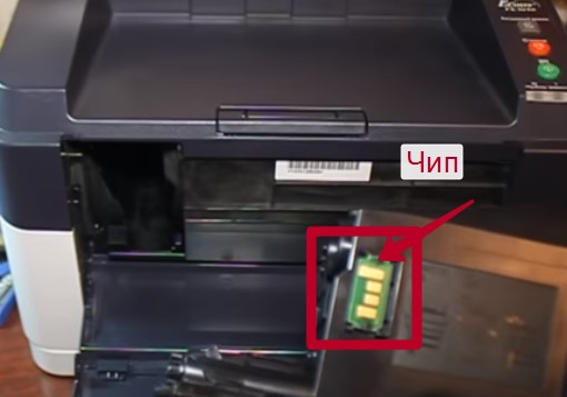
Картридж в данной модели проверяется двумя способами: датчиком наличия тонера (установлен внутри принтера) и специальным чипом (небольшая платка на картридже).
Датчик проверяет, есть ли необходимое количество тонера в картридже, а чип считает, сколько листов вы напечатали, используя данный картридж, и не даст напечатать больше, чем положено. Ошибка будет в любом случае.
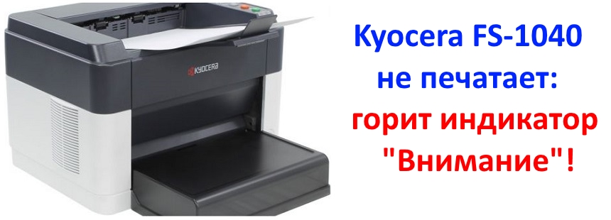
У принтера Kyocera FS-1040 горит лампочка «Внимание» и не запускается печать? Инструкция по исправлению ошибок!
Если у принтера Kyocera FS-1040 горит лампочка «Внимание» и не запускается печать, тогда первое, что вам потребуется сделать – определить ошибку.
Для этого нужно ознакомиться с уведомлением от фирменного программного обеспечения «Client Tool», установка которого осуществляется из комплектного диска. Если носитель был утерян, скачайте исходные файлы в Центре поддержки пользователей Kyocera [перейти].
Но даже без «Client Tool» можно разобраться в возможной причине отказа принтера FS-1040 от печати, обратив внимание на частоту мерцания индикатора.
Медленное мерцание индикатора
закончилась бумага
тонер в картридже на исходе
Быстрое мерцание индикатора
идентификация неоригинального картриджа
внутренняя память принтера переполнена
(большие объемы печати)
лоток бумаги переполнен
замятие бумаги
Постоянный свет индикатора
фотобарабан не работает
открыта крышка
тонер в картридже закончился
Перезапуск работы принтера
Большинство вышеописанных проблем решается с помощью перезагрузки принтера и элементарных механических действий:
- поправить бумагу в лотке;
- заменить фотобарабан;
- сбросить внутреннюю память;
- закрыть крышку принтера и так далее.
Но если вы ранее заправили комплектный картридж Kyocera TK-1110 тонером, а принтер отказывается работать из-за неправильных показаний счетчика страниц или идентификации неоригинального расходника, тогда восстанавливать печать придется одним из трех популярных способов на выбор.
Способ №1. Сброс счетчика страниц / тонера
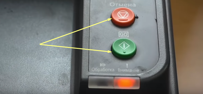
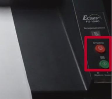
Чтобы запустить принтер Kyocera FS-1040, просто сбросьте счетчик страниц / тонера продолжительным нажатием на кнопки «Отмена» и «GO».
Проблема только в том, что сбрасывая предупреждение принтера об использовании неоригинального картриджа, можно лишиться гарантии. Поскольку устройство записывает абсолютно все ошибки в «Event Log».
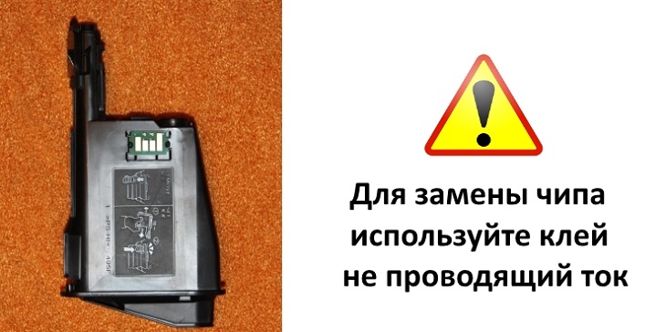
Способ №2. Замена чипа
Альтернативный вариант ручному сбросу счетчика – замена чипа. Можно сколько угодно заправлять картридж принтера Kyocera FS-1040, но благодаря установке новой защитной микросхемы устройство не распознает подмену расходника.
Испытываете проблемы с оргтехникой Kyocera? Сервисный центр МосТонер – бесплатный выезд мастера в пределах МКАД круглосуточно!
Если с аппаратом Kyocera TASKalfa 1800, Kyocera TASKalfa 2200 произошла проблема, откроется следующий экран с уведомлением.
• Индикатор [Внимание] на панели управления горит или мигает.
• На дисплее сообщений панели управления аппарата появилось сообщение об ошибке.
Если индикатор [Внимание] горит или мигает и на дисплее сообщений панели управления аппарата появилось сообщение об ошибке, проверьте KYOCERA Client Tool или Монитор состояния.
ПРИМЕЧАНИЕ Если индикаторы постоянно горят и мигают не так, как описано выше, вероятно, произошла ошибка службы. Выключите питание, отсоедините шнур питания и вставьте его обратно, после чего включите питание. Это может помочь сбросить ошибку. Если ошибка не исчезает, свяжитесь со своим представителем сервисной службы (тел. в Минске +375 17 291-28-24)
Ниже описаны неполадки, которые не могут быть устранены пользователем
|
Дисплей сообщений |
Описание |
Меры устранения |
|
Бункер отраб тонера перепол. или не уст. |
Бункер для отработанного тонера установлен неправильно |
Установите Бункер для отработанного тонера должным образом |
|
Бункер для отработанного тонера заполнен |
Замените бункер отработанного тонера |
|
|
Встряхните картр. с тонером |
Тонер слежался |
Откройте переднюю крышку аппарата и вытяните контейнер с тонером. Сильно встряхните контейнер с тонером и установите его на место |
|
Вызовите сервисный персонал. |
В аппарате произошла ошибка |
Обратите внимание на код ошибки, отображаемый в дисплее сообщений, и свяжитесь с представителем сервисной службы (тел. в Минске +375 17 291-28-24) |
|
Выньте бумагу с внутреннего лотка |
Извлеките бумагу из внутреннего лотка. Нажмите клавишу [OK], чтобы возобновить печать |
|
|
Добавьте тонер |
Закончился тонер |
Замените контейнер с тонером TK-4105 |
|
Загрузите бумагу в кассету # |
↑↓ (отображается попеременно) |
Загрузите бумагу. Нажмите клавишу [OK] и перейдите к следующему шагу. • Для выбора другого устройства подачи выберите [Выберите бумагу]. • Для печати на бумаге, в настоящее время находящейся в устройстве подачи, выберите [Продолж. без изм.] |
|
Загрузите бумагу в универсальный лоток |
↑↓ (отображается попеременно) |
Загрузите бумагу. Нажмите клавишу [OK] и перейдите к следующему шагу. • Для выбора другого устройства подачи выберите [Выберите бумагу]. • Для печати на бумаге, в настоящее время находящейся в устройстве подачи, выберите [Продолж. без изм.] |
|
Закройте автоподатчик оригиналов |
Открыт автоподатчик оригиналов |
Откройте и закройте автоподатчик оригиналов |
|
Закройте крышку автопод. оригиналов |
Открыта верхняя крышка автоподатчика оригиналов |
Откройте и закройте крышку автоподатчика оригинало |
|
Закройте переднюю крышку |
Открыта передняя крышка |
Откройте и закройте переднюю крышку |
|
Закройте правую крышку # |
Открыта какая-либо крышка |
Откройте и закройте крышку, обозначенную на экране |
|
Замятие бумаги. (DP) |
В автоподатчике произошло замятие бумаги. |
См. Устранение замятия бумаги в Руководстве по эксплуатации и извлеките замятую бумагу |
|
Замените МК |
Необходимо производить замену деталей комплекта техобслуживания MK-4105 (ремкомплекта) каждые 150 000 страниц печати. |
Данная операция должна производиться специалистом. Обратитесь к представителю сервисной службы (тел. в Минске +375 17 291-28-24) |
|
Замятие |
Произошло замятие бумаги в кассете или универсальном лотке |
См. Устранение замятия бумаги и извлеките замятую бумагу |
|
Извлеките оригиналы из автоподатчика |
Для продолжения работы необходимо извлечь оригиналы из автоподатчика оригиналов |
Извлеките оригиналы из автоподатчика оригиналов |
|
Кабель USB был отключен |
Кабель USB не подключен |
Нажмите клавишу [OK] и подключите кабель USB |
|
ПК выключен |
Нажмите клавишу [OK] и включите ПК |
|
|
Не удается найти KYOCERA Client Tool |
Нажмите клавишу [OK] и откройте KYOCERA Client Tool на ПК |
|
|
Макс. к-во сканируемых страниц |
Превышен предел сканирования |
Дальнейшее сканирование невозможно. Задание отменено. Нажмите клавишу [OK] |
|
Мало тонера. (Зам., когда законч.) |
Скоро понадобится заменить контейнер с тонером |
Получите новый контейнер с тонером TK-4105. |
|
Не оригинальный тонер |
Установлен контейнер с тонером не марки Kyocera |
Производитель не несет ответственности за повреждения, вызванные использованием неоригинального тонера. Мы рекомендуем использовать исключительно оригинальные контейнеры с тонером TK-4105. . |
|
Неверный ид. уч. зап. Задание отменено |
Указан неверный идентификатор учетной записи при внешней обработке задания. Задание отменено |
Нажмите клавишу [OK] |
|
Невозможна двусторонняя печать на этой бумаге |
Не возможна печать на бумаге выбранного формата или типа |
Нажмите клавишу [OK] и перейдите к следующему шагу: |
|
Недостаточно памяти. Невозможно начать выполнение задания |
Невозможно начать выполнение задания |
Повторите попытку позже |
|
Ограничено алгоритмом учета заданий(Печать) |
Задание отменено, поскольку его выполнение ограничено функцией учета заданий |
Нажмите клавишу [OK] |
|
Ограничено алгоритмом учета заданий(Сканер) |
Задание отменено, поскольку его выполнение ограничено функцией учета заданий |
Нажмите клавишу [OK] |
|
Очистите сканер |
Произошло загрязнение сканера |
Очистите щелевое стекло с помощью чистящей салфетки, поставляемой вместе с автоподатчиком оригиналов. |
|
Ошибка. Выключить |
— |
Отключите и снова включите аппарат с помощью выключателя питания |
|
Память переполнена |
Невозможно продолжить выполнение задания из-за отсутствия свободной памяти |
Измените разрешение печати с Быстр1200 до 600 dpi. См. Printer Driver User Guide |
|
Память сканера переполнена |
Дальнейшее сканирование невозможно из-за нехватки памяти сканера. |
Для отмены задания нажмите [OK] |
|
Перезагрузка печати. Задание отменено |
Предупреждение. Недостаточно памяти принтера. Задание отменено |
Нажмите клавишу [OK] |
|
Превышено ограничение учета заданий |
Превышено число распечаток из-за ограничения алгоритмом учета заданий. Достигнут предел печати |
Это задание отменено. Нажмите клавишу [OK] |
|
Уст.другую кассету |
Выбрано «Сдвиг» |
Для использования сдвига необходимо загрузить в другой лоток бумагу такого же формата, что и в выбранном устройстве подачи, но в другой ориентации |
|
Установите все оригиналы обратно и нажмите клавишу [Старт]. |
Возникает при печати двусторонних документов в режиме ручной двусторонней печати |
Извлеките оригиналы из автоподатчика оригиналов, расположите их в первоначальном порядке и положите обратно. Нажмите клавишу [OK], чтобы возобновить печать. Для отмены задания нажмите [Стоп] |
|
Установлен неизвестный тонер. ПК |
Региональная спецификация контейнера с тонером не соответствует спецификации аппарата |
Установите оригинальный контейнер с тонером Замените контейнер с тонером TK-4105 |
Коды ошибок принтеров Kyocera FS 1040 и Kyocera FS 1060 формируются из последовательности различных комбинаций световых индикаторов.
Ниже представлен рисунок световой индикации ошибок этих устройств, с примером расшифровки световой индикации в числовой код ошибки
и в самом низу — таблица расшифровки кодов ошибок.
Если произошел какой-то сбой в работе, загораются оба световых индикатора на 5 секунд, затем они выключаются на 2 секунды,
потом начинается индикация ошибки (мигание индикаторов в разной последовательности) с интервалом 0,8 сек.
В примере ниже разобран код ошибки 4631.
У принтера Kyocera FS-1040 горит лампочка «Внимание» и не запускается печать? Инструкция по исправлению ошибок!
Если у принтера Kyocera FS-1040 горит лампочка «Внимание» и не запускается печать, тогда первое, что вам потребуется сделать – определить ошибку.
Для этого нужно ознакомиться с уведомлением от фирменного программного обеспечения «Client Tool», установка которого осуществляется из комплектного диска. Если носитель был утерян, скачайте исходные файлы в Центре поддержки пользователей Kyocera [перейти].
Но даже без «Client Tool» можно разобраться в возможной причине отказа принтера FS-1040 от печати, обратив внимание на частоту мерцания индикатора.
Медленное мерцание индикатора
закончилась бумага
тонер в картридже на исходе
Быстрое мерцание индикатора
идентификация неоригинального картриджа
внутренняя память принтера переполнена
(большие объемы печати)
лоток бумаги переполнен
замятие бумаги
Постоянный свет индикатора
фотобарабан не работает
открыта крышка
тонер в картридже закончился
Перезапуск работы принтера
Большинство вышеописанных проблем решается с помощью перезагрузки принтера и элементарных механических действий:
- поправить бумагу в лотке;
- заменить фотобарабан;
- сбросить внутреннюю память;
- закрыть крышку принтера и так далее.
Но если вы ранее заправили комплектный картридж Kyocera TK-1110 тонером, а принтер отказывается работать из-за неправильных показаний счетчика страниц или идентификации неоригинального расходника, тогда восстанавливать печать придется одним из трех популярных способов на выбор.
Способ №1. Сброс счетчика страниц / тонера
Чтобы запустить принтер Kyocera FS-1040, просто сбросьте счетчик страниц / тонера продолжительным нажатием на кнопки «Отмена» и «GO».
Проблема только в том, что сбрасывая предупреждение принтера об использовании неоригинального картриджа, можно лишиться гарантии. Поскольку устройство записывает абсолютно все ошибки в «Event Log».
Способ №2. Замена чипа
Альтернативный вариант ручному сбросу счетчика – замена чипа. Можно сколько угодно заправлять картридж принтера Kyocera FS-1040, но благодаря установке новой защитной микросхемы устройство не распознает подмену расходника.
Испытываете проблемы с оргтехникой Kyocera? Сервисный центр МосТонер – бесплатный выезд мастера в пределах МКАД круглосуточно!
Ошибочно многие пользователи считают неисправностью ситуацию, когда на корпусе принтере Куосера 1040 горит красная кнопка с сообщением «Внимание» и тот не печатает документы, которые были на него отправлены. В этом материале мы рассмотрим, в каких случаях такое происходить, что делать, как быстро самостоятельно в домашних условиях все исправить без обращения в сервисный центр. Инструкция применима ко многим моделям фирмы Kyocera. Для примера, из-за своей популярности взят fs1040.
Значения мигания индикаторов
- Ничего не светится и уведомлений нет, то это гласит о полной готовности устройства работать.
- Медленное мигание кнопки сигнализирует об отсутствии бумаги в лотке или о низком уровне порошка в картридже.
- Более быстрое мигание лампочки: лист бумаги застрял внутри устройства, финишный лоток полностью занят и новые отпечатки уже не помещаются, заполнена вся память принтера, используется неоригинальный расходный материал.
- Индикатор светится и не гаснет. Проверьте закрыты ли крышки. Возможно уже полностью закончился тонер для печати.
Если возникают затруднения с определением причин сообщения «Внимание», то можно воспользоваться специальным программным обеспечением от инженеров компании — «Kyocera Client Tool». Эта утилита поможет более точно диагностировать проблему. Найти ее можно на сайте компании или на диске с драйверами к принтеру.
Способы решения проблемы
Сброс сообщения о неоригинальном тонере на Kyocera fs 1040
Если варианты выше не дали положительных результатов, то, скорее всего, проблема в самом картридже. Дело в том, что он оборудован датчиком уровня тонера и чипом, которые следят за количеством распечатанных листов. Когда расходный материал заканчивается или, по данным чипа, должен был кончиться, то печать блокируется до замены на новый картридж. Что и случилось в нашей ситуации.
Есть три варианта решения проблемы:
- Купить новый картридж и продолжить печать им. Стоит он не дешево.
- После каждого пополнения порошка следует менять чип, который с нуля начнет считать количество напечатанных документов.
- Сбросить счетчик на чипе. Сделать это несложно, но нужно выполнять при каждом включении аппарата.
Инструкция по сбросу:
- Включите аппарат.
- Дождитесь пока остановиться мотор и начнет мигать красная лампочка.
- Одновременно на 5–7 секунд нажимаем кнопки «Старт» и «Отмена».

- Держим пока не начнет мигать красный с зеленым по очереди.
- Ждем пока процесс завершиться.
- Пробуем печатать.
Важно знать
Согласно гарантийному листу от компании, она не несет ответственности и снимает с себя гарантийные обязательства, если покупатель начнет использовать неоригинальный тонер или другие расходные материалы. Но, как показывает практика, многие владельцы активно используют возможность сбрасывания счетчиков, их замены и использования альтернативных взаимозаменяемых чернил. Это действительно позволяет отлично сэкономить.
Видео
- Code: 0100
- Description: Backup memory read/write error (NOR)
Flash returns an abnormal status. - Causes: Defective flash memory.
- Remedy: Defective flash memory. Replace the main PWB and check for correct operation.
Defective main PWB. Replace the main PWB and check for correct operation.
- Code: 0120
- Description: MAC address data error For data in which the MAC address is invalid.
- Causes: Defective flash memory.
- Remedy: Replace the main PWB and check for correct operation.
- Code: 0190
- Description: Backup memory error (engine) Unable to read the main PWB IC.
- Causes: Defective flash memory. Defective main PWB.
- Remedy: Defective flash memory. Replace the main PWB and check for correct operation.
Defective main PWB. Replace the main PWB and check for correct operation.
- Code: 0630
- Description: Scan DMA error Unable to transfer DMA.
- Causes: Defective main PWB.
- Remedy: Replace the main PWB and check for correct operation.
- Code: 2000
- Description: Main motor error
Pulse is not detected after 1000msec. Motor won’t stabilize after 300msec. - Causes: Defective connector cable or poor contact in the connector. Defective drive transmission system of motor. Defective motor. Defective main PWB.
- Remedy: Defective connector cable or poor contact in the connector. Reinsert the connector. Also check for continuity within the connector cable. If none, replace the cable. main motor and Relay PWB (YC4) Relay PWB and main PWB (YC14).
Defective drive transmission system of motor. Check if the gears rotate smoothly. If not, grease the bushes and gears. Check for broken gears and replace if any.
Defective motor. Replace the main motor.
Defective main PWB. Replace the main PWB and check for correct operation.
- Code: 4000
- Description: Polygon motor synchronize error
Polygon motor is not stabilized within 15 s since the motor is activated. After polygon motor is stabilized, the ready signal is not detected for 7 s continuously. - Causes: Defective connector cable or poor contact in the connector. Defective polygon motor. Defective main PWB.
- Remedy: Defective connector cable or poor contact in the connector. Reinsert the connector. Also check for continuity within the connector cable. If none, replace the cable. Polygon motor and main PWB (YC17)
Defective polygon motor. Replace the laser scanner unit.
Defective main PWB. Replace the main PWB and check for correct operation.
- Code: 4200
- Description: BD stability error
The BD signal is not detected for 1000 ms after processing the compulsion lighting. At the interrupt in VSYNC, the BD error is detected continuously for 10 times in 400 ms intervals. - Causes: Defective connector cable or poor contact in the connector. Defective APC PWB. Defective main PWB.
- Remedy: Defective connector cable or poor contact in the connector. Reinsert the connector. Also check for continuity within the connector cable. If none, replace the cable. Laser scanner unit (YC1) and main PWB (YC5)
Defective APC PWB. Replace the laser scanner unit.
Defective main PWB. Replace the main PWB and check for correct operation.
- Code: 6000
- Description: Broken fuser heater
The temperature does not reach 100° C/212 °F after the fuser heater lamp has been turned on continuously for 30 s. At the time of 20 degrees or less from specified temperature, the fuser temperature does not rise by 2 degrees or more after the fuser heater lamp has been turned on continuously for 8 s.(during ready or during print) - Causes: Defective connector cable or poor contact in the connector. Fuser thermostat triggered. Defective fuser heater. Defective main PWB.
- Remedy: Defective connector cable or poor contact in the connector. Reinsert the connector. Also check for continuity within the connector cable. If none, replace the cable. fuser heater lamp and Power source PWB (YC102).
Fuser thermostat triggered. Replace the fuser unit.
Defective fuser heater. Replace the fuser unit.
Defective main PWB. Replace the main PWB and check for correct operation.
- Code: 6020
- Description: Abnormally high fuser thermistor temperature
Fuser thermistor detects a temperature higher than 210°C/410°F for 3 s - Causes: Deformed connector pin. Shorted fuser thermistor. Defective power source PWB. Defective main PWB.
- Remedy: Deformed connector pin. If the I/F connector pins of the fuser unit and the main unit are deformed owing to foreign matters, such as paper dusts, replace the connectors or the units including the connectors.
Shorted fuser thermistor. Replace the fuser unit.
Defective power source PWB. Replace the power source PWB.
Defective main PWB. Replace the main PWB and check for correct operation.
- Code: 6030
- Description: Broken fuser thermistor wire
Average input AD given by the thermistor is less than 2 for 300msec. - Causes: Defective connector cable or poor contact in the connector. Broken fuser thermistor wire. Fuser thermostat triggered. Defective main PWB.
- Remedy: Defective connector cable or poor contact in the connector. Reinsert the connector. Also check for continuity within the connector cable. If none, replace the cable. Fuser unit and main PWB (YC15)
Broken fuser thermistor wire. Replace the fuser unit.
Fuser thermostat triggered. Replace the fuser unit.
Defective main PWB. Replace the main PWB and check for correct operation.
- Code: 6400
- Description: Fixing control zerocross signal error
The ZCROSS signal does not reach the main PWB for more than 2 s. - Causes: Defective connector cable or poor contact in the connector. Defective power source PWB. Defective main PWB.
- Remedy: Defective connector cable or poor contact in the connector. Reinsert the connector. Also check for continuity within the connector cable. If none, replace the cable. Power source PWB (YC103) and main PWB (YC12)
Defective power source PWB. Replace the power source PWB.
Defective main PWB. Replace the main PWB and check for correct operation.
Коды ошибок принтеров Kyocera FS 1040 и Kyocera FS 1060 формируются из последовательности различных комбинаций световых индикаторов.
Ниже представлен рисунок световой индикации ошибок этих устройств, с примером расшифровки световой индикации в числовой код ошибки
и в самом низу — таблица расшифровки кодов ошибок.
Если произошел какой-то сбой в работе, загораются оба световых индикатора на 5 секунд, затем они выключаются на 2 секунды,
потом начинается индикация ошибки (мигание индикаторов в разной последовательности) с интервалом 0,8 сек.
В примере ниже разобран код ошибки 4631.
Данную статью мы писали, что бы рассказать об одной из самых распространенных ошибках у принтеров Kyocera: когда мы видим, что на панели появился красный индикатор, а вместе с этим не печатает принтер.
У данного индикатора, в зависимости от цвета (желтый, оранжевый или красный) у этой модели, может находится в 4 состояниях.
1. Индикатор не горит.
— принтер находится в исправном состоянии и готов к печати.
2. Индикатор медленно мигает.
— в лотке закончилась бумага для печати;
— тонер в картридже скоро закончиться.
3. Индикатор мигает быстро.
— в принтере произошло замятие бумаги;
— лоток выхода бумаги переполнен (рассчитан примерно на 150 листов);
— недостаточно внутренней памяти (например, при печати сложной графики);
— принтер определил, что картридж с тонером – не оригинальный.
4. Индикатор светиться постоянно.
— открыта одна из крышек устройства (или неисправен датчик закрытия крышки);
— проблема с блоком барабана;
— ресурс тонер-картриджа закончился.
Kyocera принтер не печатает
Большую помощь при уточнении ошибки сможет оказать специальная программа «KYOCERA Client Tool.
Программа устанавливается с диска, который был в комплекте с принтером. На Kyocera fs 1040 сброс счетчика делается очень легко.
Итак, что же всё-таки делать, если индикатор «Внимание мешает нормальной работе принтера.
Первое, что нужно сделать – это выключить принтер из сети, подождать некоторое время и включить повторно.
Второе, проверить наличие в лотке бумаги, нет ли замятия бумаги внутри принтера и не переполнен ли выходной лоток.
Если проблема, таким образом, не устранилась, то остается последний и самый распространенный вариант – тонер картридж.
Картридж в данной модели проверяется двумя способами: датчиком наличия тонера (установлен внутри принтера) и специальным чипом (небольшая платка на картридже).
Датчик проверяет, есть ли необходимое количество тонера в картридже, а чип считает, сколько листов вы напечатали, используя данный картридж, и не даст напечатать больше, чем положено. Ошибка будет в любом случае.
У принтера Kyocera FS-1040 горит лампочка «Внимание» и не запускается печать? Инструкция по исправлению ошибок!
Если у принтера Kyocera FS-1040 горит лампочка «Внимание» и не запускается печать, тогда первое, что вам потребуется сделать – определить ошибку.
Для этого нужно ознакомиться с уведомлением от фирменного программного обеспечения «Client Tool», установка которого осуществляется из комплектного диска. Если носитель был утерян, скачайте исходные файлы в Центре поддержки пользователей Kyocera [перейти].
Но даже без «Client Tool» можно разобраться в возможной причине отказа принтера FS-1040 от печати, обратив внимание на частоту мерцания индикатора.
Медленное мерцание индикатора
закончилась бумага
тонер в картридже на исходе
Быстрое мерцание индикатора
идентификация неоригинального картриджа
внутренняя память принтера переполнена
(большие объемы печати)
лоток бумаги переполнен
замятие бумаги
Постоянный свет индикатора
фотобарабан не работает
открыта крышка
тонер в картридже закончился
Перезапуск работы принтера
Большинство вышеописанных проблем решается с помощью перезагрузки принтера и элементарных механических действий:
- поправить бумагу в лотке;
- заменить фотобарабан;
- сбросить внутреннюю память;
- закрыть крышку принтера и так далее.
Но если вы ранее заправили комплектный картридж Kyocera TK-1110 тонером, а принтер отказывается работать из-за неправильных показаний счетчика страниц или идентификации неоригинального расходника, тогда восстанавливать печать придется одним из трех популярных способов на выбор.
Способ №1. Сброс счетчика страниц / тонера
Чтобы запустить принтер Kyocera FS-1040, просто сбросьте счетчик страниц / тонера продолжительным нажатием на кнопки «Отмена» и «GO».
Проблема только в том, что сбрасывая предупреждение принтера об использовании неоригинального картриджа, можно лишиться гарантии. Поскольку устройство записывает абсолютно все ошибки в «Event Log».
Способ №2. Замена чипа
Альтернативный вариант ручному сбросу счетчика – замена чипа. Можно сколько угодно заправлять картридж принтера Kyocera FS-1040, но благодаря установке новой защитной микросхемы устройство не распознает подмену расходника.
Испытываете проблемы с оргтехникой Kyocera? Сервисный центр МосТонер – бесплатный выезд мастера в пределах МКАД круглосуточно!
If the part causing the problem was not supplied, use the unit including the part for replacement.
Release is performed by power supply OFF/ON.
Code
Contents
0100
Backup memory read/write
error (NOR)
Flash returns an abnormal
status.
0120
MAC address data error
For data in which the MAC
address is invalid.
0190
Backup memory error
(engine)
Unable to read the main PWB
IC.
0630
Scan DMA error
Unable to transfer DMA.
2000
Main motor error
Pulse is not detected after
1000msec.
Motor won’t stabilize after
300msec.
4000
Polygon motor synchronize
error
Polygon motor is not stabi-
lized within 15 s since the
motor is activated.
After polygon motor is stabi-
lized, the ready signal is not
detected for 7 s continuously.
4200
BD stability error
The BD signal is not detected
for 1000 ms after processing
the compulsion lighting.
At the interrupt in VSYNC, the
BD error is detected continu-
ously for 10 times in 400 ms
intervals.
Causes
Defective flash
Replace the main PWB and check for cor-
memory.
rect operation (see page 1-5-7).
Defective main
Replace the main PWB and check for cor-
PWB.
rect operation (see page 1-5-7).
Defective flash
Replace the main PWB and check for cor-
memory.
rect operation (see page 1-5-7).
Defective flash
Replace the main PWB and check for cor-
memory.
rect operation (see page 1-5-7).
Defective main
Replace the main PWB and check for cor-
PWB.
rect operation (see page 1-5-7).
Defective main
Replace the main PWB and check for cor-
PWB.
rect operation (see page 1-5-7).
Defective connec-
Reinsert the connector. Also check for conti-
tor cable or poor
nuity within the connector cable. If none,
contact in the con-
replace the cable.
nector.
main motor and Relay PWB (YC4)
Relay PWB and main PWB (YC14).
Defective drive
Check if the gears rotate smoothly. If not,
transmission sys-
grease the bushes and gears. Check for
tem of motor.
broken gears and replace if any.
Defective motor.
Replace the main motor.
Defective main
Replace the main PWB and check for cor-
PWB.
rect operation (see page 1-5-7).
Defective connec-
Reinsert the connector. Also check for conti-
tor cable or poor
nuity within the connector cable. If none,
contact in the con-
replace the cable.
nector.
Polygon motor and main PWB (YC17)
Defective polygon
Replace the laser scanner unit
motor.
(see page 1-5-12).
Defective main
Replace the main PWB and check for cor-
PWB.
rect operation (see page 1-5-7).
Defective connec-
Reinsert the connector. Also check for conti-
tor cable or poor
nuity within the connector cable. If none,
contact in the con-
replace the cable.
nector.
Laser scanner unit (YC1) and main PWB
(YC5)
Defective APC
Replace the laser scanner unit
PWB.
(see page 1-5-12).
Defective main
Replace the main PWB and check for cor-
PWB.
rect operation (see page 1-5-7).
1-4-6
Check procedures/
corrective measures
2M2/2M3