
- Code: 0030
- Description: FAX control PWB system error
Processing with the fax software was disabled due to a software problem. - Remedy: FAX control PWB: 1. Turn the main power swtch off and after 5 seconds, re-mount the FAX controller PWB, then turn power on. 2. Reinstall the fax software. 3. Replace the FAX control PWB.
- Code: 0070
- Description: FAX control PWB incompatible detection error
Abnormal detection of FAX control PWB incompatibility In the initial communication with the FAX control PWB, any normal communication command is not transmitted. - Remedy: FAX control PWB (The FAX PWB installed will not be the one designed for the machine.): 1. Install the FAX system designed for the model. 2. Reinstall the fax software.
- Code: 0080
- Description: Option printing system device error.
The version of the FPGA for Fiery control is not readable. (Defective FPGA) - Remedy: Defective FPGA for printing system control.: 1. Turn the main power swtch off and after 5 seconds, then turn power on. 2. Replace the main PWB
- Code: 0100
- Description: Backup memory device error
- Remedy: EEPROM(main PWB): 1. Turn the main power swtch off and after 5 seconds, then turn power on. 2. Check that the EEPROM on the main circuit PWB is peroperly installed on the main circuit PWB and, if not, re-install it. 3. Replace the main PWB.
- Code: 0120
- Description: MAC address data error
For data in which the MAC address is invalid. - Remedy: EEPROM(main PWB): 1. Turn the main power swtch off and after 5 seconds, then turn power on. 2. Check the MAC address on the network status page. 3. If it is blank, obtain an EEPROM with its MAC address written from the service support and install. 4. Replace the main PWB.
- Code: 0150
- Description: Backup memory read/write error (engine PWB)
No response is issued from the device in reading/writing for 5 ms or more and this problem is repeated 5 times successively. Mismatch of reading data from 2 locations occurs 8 times successively. Mismatch between writing data and reading data occurs 8 times successively. - Remedy: EEPROM(Engine PWB): 1. Turn the main power swtch off and after 5 seconds, then turn power on. 2. Check that the EEPROM is peroperly installed on the engine PWB and reinstall it. 3. Replace the engine PWB. 4. Check the EEPROM and if the data are currupted, contact the service support.
- Code: 0160
- Description: Backup memory data error (engine PWB)
Reading data from EEPROM is abnormal. - Remedy: EEPROM: 1. Turn the main power swtch off and after 5 seconds, then turn power on. 2. Execute U021 — memory initializing 3. If the EEPROM data are currupted, contact the service support.
- Code: 0170
- Description: Billing counting error
The values on the main circuit PWB and on the engine do not match for any of charging counter, life counter, and scanner counter. - Remedy: EEPROM: 1. Check that the EEPROMs installed in the main PWB and the engine PWB are correct and, if not, use the correct EEPROM for the model. 2. If the EEPROM data are currupted, contact the service support.
Main PWB: Replace the main PWB.
Engine PWB: Replace the engine PWB
- Code: 0180
- Description: Machine number mismatch
Machine number of main and engine does not match. - Remedy: Data damage of EEPROM: 1. Confirm the machine data for the main and engine units by using U004. 2. If the serial number data of different models is alternately displayed, install the correct EEPROM in the PWB of the wrong serial number data. 3. Contact the Service Support.
- Code: 0350
- Description: Panel PWB communication error (electronic volume I2C communication error)
NACK is received during I2C communication -> retried 5 times -> rebooting command sent -> retried 5 times If NACK is still received. - Remedy: Operation PWB: 1. Turn the main power swtch off and after 5 seconds, then turn power on. 2. Confirm that the wiring connector is firmly connected and, if necessary, connect the connector all the way in. Operation PWB (YC10) and Main PWB (YC6) 3. If the wiring is disconnected, shorted or grounded, replace the wiring.
Main PWB: Replace the main PWB.
- Code: 0620
- Description: FAX image DIMM error
1. The Fax image DIMM has not been installed. 2. Fax image DIMM access error. - Remedy: FAX image DIMM: 1. Install the FAX image DIMM supplied in the FAX system onto the main PWB. 2. Firmly install the FAX image DIMM again onto the main board. 3. Check the FAX image DIMM terminals and remove any foreign objects that may be adhered to it. 4. Replace with a new FAX image DIMM.
- Code: 0630
- Description: DMA error
DMA transmission of image data does not complete within the specified period of time. - Remedy: DP CIS: 1. Reconnect the CIS signal line. 2. Confirm that the CIS connector terminals are firmly connected. Insert the connector all the way in. 3. If the wiring is disconnected, shorted or grounded, replace the wiring.
DP main PWB: Main PWB 1. Confirm that the wiring connector is firmly connected and, if necessary, connect the connector all the way in. 2. If the wiring is disconnected, shorted or grounded, replace the wiring. Wiring that connects the CIS and the DP controller PWB. Wiring that connects the DP main PWB and the main PWB. 3. Replace the DP main PWB. 4. Replace the main PWB.
- Code: 0640
- Description: Hard disk error
The hard disk cannot be accessed. - Remedy: HDD: 1. If an abnormal noise is heard from the HDD, replace the HDD. 2. Check the SATA wiring between the HDD and the main circuit PWB for loose connection, disconnection and damages, and that it is connected into the correct terminal. Main PWB: YC1,YC27 YC2,YC32 (45/55 ppm model) 3. Replace the SATA cable. 4. Execute U024 to initialize (FULL) the HDD. 5. If an error is detected after executing U024, replace the HDD.
Main PWB: Replace the main PWB
- Code: 0650
- Description: FAX image DIMM check error
A fax image DIMM which was used with another machine is installed. - Remedy: FAX DIMM: 1. Confirm that a used FAX image DIMM was used instead of the FAX image DIMM contained in the FAX system. 2. If a DIMM that was used with other unit has been installed, execute maintenance mode U671 — Recovery FAX DIMM. 3. Check whether the Fax DIMM is properly inserted into the socket on the main PWB. 4. Replace with a new FAX image DIMM.
Main PWB: Replace the main PWB.
- Code: 0660
- Description: Hard disk encryption key error
- Remedy: EEPROM: 1. Execute U004 if this occurs after the EEPROM has been changed.
HDD: 1. If an abnormal noise is heard from the HDD, replace the HDD. 2. Check the SATA wiring between the HDD and the main circuit PWB for loose connection, disconnection and damages, and that it is connected into the correct terminal. Main PWB: YC1,YC27 YC2,YC32 (45/55 ppm model) 3. Replace the SATA cable. 4. Execute U024 to initialize (FULL) the HDD. 5. If an error is detected after executing U024, replace the HDD.
Main PWB: Replace the main PWB
- Code: 0670
- Description: Hard disk overwriting erasure error
- Remedy: HDD: 1. If an abnormal noise is heard from the HDD, replace the HDD. 2. Check the SATA wiring between the HDD and the main circuit PWB for loose connection, disconnection and damages, and that it is connected into the correct terminal. Main PWB: YC1,YC27 YC2,YC32 (45/55 ppm model) 3. Replace the SATA cable. 4. Execute U024 to initialize (FULL) the HDD. 5. If an error is detected after executing U024, replace the HDD.
Main PWB: Replace the main PWB.
- Code: 0800
- Description: Image processing error
JAM010X is detected twice. - Remedy: Main PWB: Replace the main PWB
- Code: 0830
- Description: FAX control PWB flash program area checksum error
A checksum error occurred with the program of the FAX control PWB. - Remedy: FAX software: 1. Reinstall the fax software.
FAX control PWB: 1. Execute initializing by U600. 2. Replace the FAX control PWB.
- Code: 0840
- Description: Faults of RTC
(“Time for maintenance T” is displayed) [Check at power up] The RTC setting has reverted to a previous state. The machine has not been powered for 5 years (compared to the settings stored periodically in the EEPROM). The RTC setting is older than 00:01 on January 1, 2000. [Checked periodically (in 5- minute interval) after powered up] The RTC setting has reverted to a state older than the last time it was checked. 10 minutes have been passed since the previous check. After C840 is detected, the machine enters in disconnection mode after the main power switch has been switched on and off and indicates ‘Maintenance T.’ - Remedy: Battery ( main PWB): 1. Make sure that the back-up batteries on the main PWB are not short-circuited. 2. Reset Maintenance T by executing U906 . 3. If the same C call is displayed when power is switched on and off, replace the back up battery. 4. If communication error (due to a noise, etc.) is present with the RTC on the main circuit PWB, check the PWB is properly grounded.
Main PWB: Replace the main PWB
- Code: 0870
- Description: PCFAX control PWB to main PWB high capacity data transfer error
High-capacity data transfer between the FAX control PWB and the main PWB of the machine was not normally performed even if the data transfer was retried the specified times. - Remedy: FAX control PWB: 1. Turn the main power swtch off and after 5 seconds, re-mount the FAX controller PWB, then turn power on. 2. Replace the FAX control PWB.
HDD: Execute U024 to initialize the HDD.
Main PWB: Replace the main PWB
- Code: 0920
- Description: Fax file system error
The backup data is not retained for file system abnormality of flash memory of the FAX control PWB. - Remedy: FAX control PWB: 1. Execute initializing by U600 (Refer to the FAX service manual). 2. Replace the FAX control PWB.
- Code: 0980
- Description: 24 V power down detect
If a 24V power disconnection signal is observed and a 12V power disconnection signal is observed simultaneously for one second. - Remedy: Power source PWB: 1. Check the +24V output is given at YC12- 1 to 3 of the power circuit PWB. 2. Replace the power source PWB
- Code: 1000
- Description: MP lift motor error
If the MP lift sensor 1 (upper limit detect) or 2 (bottom detect) is not detectable to be turned on while the MP lift motor is ascending or descending. - Remedy: Manual feed lift base elevating mechanism: 1. Check that the paper lift base of the manual feed tray can smoothly ascend and descent, if not, repair or replace. 2. Check that the lift lever is located so that it can ascend or descend by the lift motor cam and that it not damaged and, if necessary, re-install or replace the manual feed table.
MP lift motor: 1. Check that the paper elevator has been ascended. 2. Check the drive gear can rotate or they are not unusually loaded and, if necessary, replace. 3. Confirm that the wiring connector is firmly connected and, if necessary, connect the connector all the way in. MP lift motor and Relay PWB (YC3) Relay PWB (YC12) and Feed PWB1 (YC17) Feed PWB1 (YC1) and Engine PWB (YC6) 4. If the wiring is disconnected, shorted or grounded, replace the wiring. 5. Replace the MP lift motor.
MP lift sensor1 MP lift sensor2: 1. Check that the sensor is correctly positioned. 2. Confirm that the wiring connector is firmly connected and, if necessary, connect the connector all the way in. MP lift sensor1,2 and Relay PWB (YC3) Relay PWB (YC12) and Feed PWB1(YC17) Feed PWB1 (YC1) and Engine PWB (YC6) 3. If the wiring is disconnected, shorted or grounded, replace the wiring. 4. Replace the MP lift sensor1 or MP lift sensor2.
Feed PWB 2: Replace the Feed PWB 2.
Engine PWB: 1. Check the engine software and upgrade to the latest, if necessary. 2. Replace the engine PWB.
- Code: 1010
- Description: Lift motor 1 error
After cassette 1 is inserted, lift sensor 1 does not turn on within 12 s. This error is detected 5 times successively. The lock signal of the motor is detected continuously for 1 s. This error is detected 5 times successively. - Remedy: Cassette lift base elevating mechanism: Check that the cassette base can be manipulated smoothly, if not, repair or replace.
Lift motor 1: 1. Check that the cassette base has been ascended. 2. Check the drive gear can rotate or they are not unusually loaded and, if necessary, replace. 3. Confirm that the wiring connector is firmly connected and, if necessary, connect the connector all the way in. Lift motor 1 and Feed PWB 2 (YC3) Feed PWB 2 (YC1) and Engine PWB (YC4) 4. If the wiring is disconnected, shorted or grounded, replace the wiring. 5. Replace the lift motor 1.
Lift sensor 1: 1. Check that the sensor is correctly positioned. 2. Confirm that the wiring connector is firmly connected and, if necessary, connect the connector all the way in. Lift sensor 1 and Feed PWB 2 (YC8) Feed PWB 2 (YC1) and Engine PWB (YC4) 3. If the wiring is disconnected, shorted or grounded, replace the wiring. 4. Replace the lift sensor1.
Feed PWB 2: Replace the Feed PWB 2.
Engine PWB: 1. Check the engine software and upgrade to the latest, if necessary. 2. Replace the engine PWB.
- Code: 1020
- Description: Lift motor 2 error
After cassette 2 is inserted, lift sensor 2 does not turn on within 12 s. This error is detected 5 times successively. The lock signal of the motor is detected continuously for 1 s. This error is detected 5 times successively. - Remedy: Cassette lift base elevating mechanism: Check that the cassette base can be manipulated smoothly, if not, repair or replace.
Lift motor 2: 1. Check that the cassette base has been ascended. 2. Check the drive gear can rotate or they are not unusually loaded and, if necessary, replace. 3. Confirm that the wiring connector is firmly connected and, if necessary, connect the connector all the way in. Lift motor 2 and Feed PWB 2 (YC3) Feed PWB 2 (YC1) and Engine PWB (YC4) 4. If the wiring is disconnected, shorted or grounded, replace the wiring. 5. Replace the lift motor 2.
Lift sensor 2: 1. Check that the sensor is correctly positioned. 2. Confirm that the wiring connector is firmly connected and, if necessary, connect the connector all the way in. Lift sensor 2 and Feed PWB 2 (YC8) Feed PWB 2 (YC1) and Engine PWB (YC4) 3. If the wiring is disconnected, shorted or grounded, replace the wiring. 4. Replace the lift sensor2.
Feed PWB 2: Replace the Feed PWB 2.
Engine PWB: 1. Check the engine software and upgrade to the latest, if necessary. 2. Replace the engine PWB.
- Code: 1030
- Description: PF lift motor 1 error (paper feeder)
After cassette 3 is inserted, PF lift sensor 1 does not turn on within 12 s. This error is detected 5 times successively. During driving the motor, the lift overcurrent protective monitor signal is detected for 1 s or more 5 times successively. However, the first 1 s after motor is turned on is excluded from detection. - Remedy: Cassette lift base elevating mechanism: Check that the cassette base can be manipulated smoothly, if not, repair or replace.
PF Lift motor 1: 1. Check that the cassette base has been ascended. 2. Check the drive gear can rotate or they are not unusually loaded and, if necessary, replace. 3. Confirm that the wiring connector is firmly connected and, if necessary, connect the connector all the way in. PF Lift motor 1 and main PWB (YC7) 4. If the wiring is disconnected, shorted or grounded, replace the wiring. 5. PFReplace the lift motor 1.
PF Lift sensor 1: 1. Check that the sensor is correctly positioned. 2. Confirm that the wiring connector is firmly connected and, if necessary, connect the connector all the way in. PF Lift sensor 1 and PF main PWB (YC7) 3. If the wiring is disconnected, shorted or grounded, replace the wiring. 4. Replace the lift sensor 1.
PF main PWB: Replace the PF main PWB (Refer to the service manual for the paper feeder).
- Code: 1040
- Description: PF lift motor 2 error (paper feeder)
After cassette 4 is inserted, PF lift sensor 2 does not turn on within 12 s. This error is detected 5 times successively. During driving the motor, the lift overcurrent protective monitor signal is detected for 1 s or more 5 times successively. However, the first 1 s after motor is turned on is excluded from detection. - Remedy: Cassette lift base elevating mechanism: Check that the cassette base can be manipulated smoothly, if not, repair or replace.
PF Lift motor 2: 1. Check that the cassette base has been ascended. 2. Check the drive gear can rotate or they are not unusually loaded and, if necessary, replace. 3. Confirm that the wiring connector is firmly connected and, if necessary, connect the connector all the way in. PF Lift motor 2 and PF main PWB (YC7) 4. If the wiring is disconnected, shorted or grounded, replace the wiring. 5. Replace the PF Lift motor2.
PF Lift sensor 2: 1. Check that the sensor is correctly positioned. 2. Confirm that the wiring connector is firmly connected and, if necessary, connect the connector all the way in. PF Lift sensor 2 and PF main PWB (YC7) 3. If the wiring is disconnected, shorted or grounded, replace the wiring. 4. Replace the PF Lift sensor 2.
PF main PWB: Replace the PF main PWB (Refer to the service manual for the paper feeder).
- Code: 1050
- Description: SM lift motor error (side multi tray)
[45 ppm/55 ppm model] After cassette 5 is inserted, SM lift sensor does not turn on within 12 s. This error is detected 5 times successively. (Time to detect is 2 seconds at the second time and later.) During driving the motor, the lift overcurrent protective monitor signal is detected for 1 s or more 5 times successively. However, the first 1 s after motor is turned on is excluded from detection. - Remedy: Cassette lift base elevating mechanism: Check that the cassette base can be manipulated smoothly, if not, repair or replace.
SM Lift motor: 1. Check that the cassette base has been ascended. 2. Check the drive gear can rotate or they are not unusually loaded and, if necessary, replace. 3. Confirm that the wiring connector is firmly connected and, if necessary, connect the connector all the way in. SM Lift motor and SM main PWB (YC5) 4. If the wiring is disconnected, shorted or grounded, replace the wiring. 5. Replace the SM Lift motor.
SM Lift sensor: 1. Check that the sensor is correctly positioned. 2. Confirm that the wiring connector is firmly connected and, if necessary, connect the connector all the way in. SM Lift sensor and SM main PWB (YC7) 3. If the wiring is disconnected, shorted or grounded, replace the wiring. 4. Replace the SM Lift sensor.
SM main PWB: Replace the SM main PWB (Refer to the service manual for the paper feeder).
- Code: 1060
- Description: PF lift motor 1 error (side paper feeder)
[45 ppm/55 ppm model] After cassette 6 is inserted, PF lift sensor 1 does not turn on within 12 s. This error is detected 5 times successively. (Time to detect is 2 seconds at the second time and later.) During driving the motor, the lift overcurrent protective monitor signal is detected for 1 s or more 5 times successively. However, the first 1 s after motor is turned on is excluded from detection. *:The lift over-current protection monitor signal has been detected for 200ms or longer where LFC is installed. - Remedy: Cassette lift base elevating mechanism: Check that the cassette base can be manipulated smoothly, if not, repair or replace. PF Lift motor 1: 1. Check that the cassette base has been ascended. 2. Check the drive gear can rotate or they are not unusually loaded and, if necessary, replace. 3. Confirm that the wiring connector is firmly connected and, if necessary, connect the connector all the way in. PF Lift motor 1 and PF main PWB (YC7) 4. If the wiring is disconnected, shorted or grounded, replace the wiring. 5. Replace the lift motor 1.
PF Lift sensor 1: 1. Check that the sensor is correctly positioned. 2. Confirm that the wiring connector is firmly connected and, if necessary, connect the connector all the way in. PF Lift sensor1 and PF main PWB (YC5) 3. If the wiring is disconnected, shorted or grounded, replace the wiring. 4. Replace the lift sensor 1.
PF main PWB: Replace the PF main PWB (Refer to the service manual for the paper feeder).
- Code: 1070
- Description: PF lift motor 2 error (side paper feeder)
[45 ppm/55 ppm model] After cassette 7 is inserted, PF lift sensor 2 does not turn on within 12 s. This error is detected 5 times successively. (Time to detect is 2 seconds at the second time and later.) During driving the motor, the lift overcurrent protective monitor signal is detected for 1 s or more 5 times successively. However, the first 1 s after motor is turned on is excluded from detection. *:The lift over-current protection monitor signal has been detected for 200ms or longer where LFC is installed. - Remedy: Cassette lift base elevating mechanism: Check that the cassette base can be manipulated smoothly, if not, repair or replace.
PF Lift motor2: 1. Check that the cassette base has been ascended. 2. Check the drive gear can rotate or they are not unusually loaded and, if necessary, replace. 3. Confirm that the wiring connector is firmly connected and, if necessary, connect the connector all the way in. PF Lift motor 2 and PF main PWB (YC7) 4. If the wiring is disconnected, shorted or grounded, replace the wiring. 5. Replace the PF Lift motor2
PF Lift sensor2: 1. Check that the sensor is correctly positioned. 2. Confirm that the wiring connector is firmly connected and, if necessary, connect the connector all the way in. PF Lift sensor 2 and PF main PWB (YC4) 3. If the wiring is disconnected, shorted or grounded, replace the wiring. 4. PFReplace the lift sensor2.
PF main PWB: Replace the PF main PWB (Refer to the service manual for the paper feeder).
- Code: 1100
- Description: PF lift motor 1 error (large capacity feeder)
After cassette 3 is inserted, PF lift sensor 1 does not turn on within 23 s. This error is detected 5 times successively. (Time to detect is 2 seconds at the second time and later.) During driving the motor, the lift overcurrent protective monitor signal is detected for 200 ms or more 5 times successively. However, the first 1 s after PF lift motor 1 is turned on is excluded from detection. - Remedy: Paper feeder lift base elevating mechanism: Check that the cassette base can be manipulated smoothly, if not, repair or replace.
PF Lift motor1: 1. Check that the cassette base has been ascended. 2. Check the drive gear can rotate or they are not unusually loaded and, if necessary, replace. 3. Confirm that the wiring connector is firmly connected and, if necessary, connect the connector all the way in. PF Lift motor 1 and PF main PWB (YC7) 4. If the wiring is disconnected, shorted or grounded, replace the wiring. 5. Replace the PF lift motor1.
PF Lift sensor1: 1. Check that the sensor is correctly positioned. 2. Confirm that the wiring connector is firmly connected and, if necessary, connect the connector all the way in. PF Lift sensor 1 and PF main PWB (YC5) 3. If the wiring is disconnected, shorted or grounded, replace the wiring. 4. Replace the PF lift sensor1.
PF main PWB: Replace the PF main PWB (Refer to the service manual for the paper feeder).
- Code: 1110
- Description: PF lift motor 2 error (large capacity feeder)
After cassette 4 is inserted, PF lift sensor 2 does not turn on within 23 s. This error is detected 5 times successively. (Time to detect is 2 seconds at the second time and later.) During driving the motor, the lift overcurrent protective monitor signal is detected for 200 ms or more 5 times successively. However, the first 1 s after PF lift motor 2 is turned on is excluded from detection. - Remedy: Paper feeder lift base elevating mechanism: Check that the cassette base can be manipulated smoothly, if not, repair or replace.
PF Lift motor 2: 1. Check that the cassette base has been ascended. 2. Check the drive gear can rotate or they are not unusually loaded and, if necessary, replace. 3. Confirm that the wiring connector is firmly connected and, if necessary, connect the connector all the way in. PF Lift motor 2 and PF main PWB (YC7) 4. If the wiring is disconnected, shorted or grounded, replace the wiring. 5. Replace the PF Lift motor2.
PF Lift sensor2: 1. Check that the sensor is correctly positioned. 2. Confirm that the wiring connector is firmly connected and, if necessary, connect the connector all the way in. PF Lift sensor 2 and PF main PWB (YC4) 3. If the wiring is disconnected, shorted or grounded, replace the wiring. 4. Replace the PF Lift sensor 2.
PF main PWB: Replace the PF main PWB (Refer to the service manual for the paper feeder).
- Code: 1140
- Description: SD lift motor error (side deck)
After cassette 5 is inserted, SD lift sensor does not turn on within 30 s. The lock signal of the motor is detected continuously for 200 ms. - Remedy: Paper feeder lift base elevating mechanism: Check that the cassette base can be manipulated smoothly, if not, repair or replace.
SD Lift motor: 1. Check that the cassette base has been ascended. 2. Check the drive gear can rotate or they are not unusually loaded and, if necessary, replace. 3. Confirm that the wiring connector is firmly connected and, if necessary, connect the connector all the way in. SD Lift motor and SD main PWB (YC8) 4. If the wiring is disconnected, shorted or grounded, replace the wiring. 5. Replace the SD Lift motor.
SD Lift sensor: 1. Check that the sensor is correctly positioned. 2. Confirm that the wiring connector is firmly connected and, if necessary, connect the connector all the way in. SD Lift sensor and SD main PWB (YC5) 3. If the wiring is disconnected, shorted or grounded, replace the wiring. 4. Replace the SD Lift sensor.
SD main PWB: Replace the SD main PWB (Refer to the service manual for the paper feeder).
- Code: 1250
- Description: SM multi feed sensor communication error (side multi tray)
[45 ppm/55 ppm model] A communication error is detected 3 times in succession. - Remedy: Side multi tray: Check the wiring connection status with the main unit and, if necessary, try connecting it again.
SM main PWB: 1. Confirm that the wiring connector is firmly connected and, if necessary, connect the connector all the way in. SM main PWB (YC1) and Engine PWB (YC19) 2. If the wiring is disconnected, shorted or grounded, replace the wiring. 3. Replace the SM main PWB (Refer to the service manual for the paper feeder).
Engine PWB: 1. Check the engine software and upgrade to the latest, if necessary. 2. Replace the engine PWB .
- Code: 1350
- Description: SM multi feed sensor error (side multi tray)
[45 ppm/55 ppm model] The SM multi feed sensor has detected multi feeding 5 times successively. - Remedy: SM multi feed sensor: 1. Check that the sensor is correctly positioned. 2. Confirm that the wiring connector is firmly connected and, if necessary, connect the connector all the way in. SM multi feed sensor and SM main PWB (YC11) 3. If the wiring is disconnected, shorted or grounded, replace the wiring. 4. Replace the SM multi feed sensor.
SM main PWB: Replace the PF main PWB (Refer to the service manual for the paper feeder).
- Code: 1400
- Description: Rotary guide motor error
The guide sensor is not detected to be on at the home position detection with the rotary guide for three times in a row. - Remedy: Rotary guide motor: 1. Check the rotary guide and drive gear can rotate or they are not unusually loaded and, if necessary, replace. 2. Confirm that the wiring connector is firmly connected and, if necessary, connect the connector all the way in. Rotary guide motor and BR PWB (YC5) 3. If the wiring is disconnected, shorted or grounded, replace the wiring. 4. Replace the rotary guide motor.
BR PWB: Replace the BR PWB.
- Code: 1410
- Description: Rotary de-curler error
If the de-curler won’t turn On/ Off despite it has been activated for 400 steps during waiting for the de-curler sensor to be On/Off three times in a row. - Remedy: Rotary de-curler motor: 1. Check the rotary de-curler and drive gear can rotate or they are not unusually loaded and, if necessary, replace. 2. Confirm that the wiring connector is firmly connected and, if necessary, connect the connector all the way in. Rotary de-curler motor and BR PWB (YC5) 3. If the wiring is disconnected, shorted or grounded, replace the wiring. 4. Replace the rotary de-curler motor.
BR PWB: Replace the BR PWB.
- Code: 1450
- Description: SM multi feed sensor backup error (side multi tray)
[45 ppm/55 ppm model] When writing the data, read and write data does not match 3 times in succession. Deleting a block has failed three times in a row. Writing won’t complete in 200 ms after writing has commenced. - Remedy: SM multi feed sensor: 1. Confirm that the wiring connector is firmly connected and, if necessary, connect the connector all the way in. SM multi feed sensor and SM main PWB (YC11) 2. If the wiring is disconnected, shorted or grounded, replace the wiring. 3. Replace the SM multi feed sensor.
SM main PWB: Replace the PF main PWB (Refer to the service manual for the paper feeder).
- Code: 1710
- Description: Side multi tray incompatible detection error
[30 ppm/35 ppm model] The side multi tray has been installed with a device to which it is incompatible. - Remedy: The side multi tray is installed with a device to which it is incompatible: Install the side multi-tray with the target model.
- Code: 1800
- Description: Paper feeder communication error
A communication error from paper feeder is detected 10 times in succession. - Remedy: Paper feeder: Check the wiring connection status with the main unit and, if necessary, try connecting it again.
PF main PWB: 1. Confirm that the wiring connector is firmly connected and, if necessary, connect the connector all the way in. PF main PWB (YC13) and Engine PWB (YC19) 2. If the wiring is disconnected, shorted or grounded, replace the wiring. 3. Replace the PF main PWB (Refer to the service manual for the paper feeder).
Engine PWB: 1. Check the engine software and upgrade to the latest, if necessary. 2. Replace the engine PWB.
- Code: 1810
- Description: Side multi tray communication error
[45 ppm/55 ppm model] A communication error from side multi tray is detected 10 times in succession. - Remedy: Side multi tray: Check the wiring connection status with the main unit and, if necessary, try connecting it again.
SM main PWB: 1. Confirm that the wiring connector is firmly connected and, if necessary, connect the connector all the way in. SM main PWB (YC1) and Engine PWB (YC19) 2. If the wiring is disconnected, shorted or grounded, replace the wiring. 3. Replace the SM main PWB (Refer to the service manual for the paper feeder).
Engine PWB: Check the engine software and upgrade to the latest, if necessary. Replace the engine PWB.
SM main PWB: Replace the SM main PWB (Refer to the service manual for the paper feeder).
- Code: 1820
- Description: Side paper feeder communication error
[45 ppm/55 ppm model] A communication error from paper feeder is detected 10 times in succession. - Remedy: Side paper feeder: Check the wiring connection status with the main unit and, if necessary, try connecting it again.
SM main PWB: 1. Confirm that the wiring connector is firmly connected and, if necessary, connect the connector all the way in. SM main PWB (YC1) and Engine PWB (YC19) 2. If the wiring is disconnected, shorted or grounded, replace the wiring. 3. Replace the SM main PWB (Refer to the service manual for the paper feeder).
PF main PWB: 1. Confirm that the wiring connector is firmly connected and, if necessary, connect the connector all the way in. PF main PWB (YC13) and SM main PWB (YC4) 2. If the wiring is disconnected, shorted or grounded, replace the wiring. 3. Replace the PF main PWB (Refer to the service manual for the paper feeder).
Engine PWB: 1. Check the engine software and upgrade to the latest, if necessary. 2. Replace the engine PWB.
- Code: 1900
- Description: Paper feeder EEPROM error
When writing the data, read and write data does not match 3 times in succession. - Remedy: PF main PWB (EEPROM): 1. Confirm that the wiring connector is firmly connected and, if necessary, connect the connector all the way in. 2. Replace the PF main PWB (Refer to the service manual for the paper feeder).
- Code: 1910
- Description: Side multi tray EEPROM error
[45 ppm/55 ppm model] When writing the data, read and write data does not match 3 times in succession. - Remedy: SM main PWB (EEPROM): 1. Confirm that the wiring connector is firmly connected and, if necessary, connect the connector all the way in. 2. Replace the SM main PWB (Refer to the service manual for the paper feeder).
- Code: 1920
- Description: Side paper feeder EEPROM error
[45 ppm/55 ppm model] When writing the data, read and write data does not match 3 times in succession. - Remedy: PF main PWB: 1. Confirm that the wiring connector is firmly connected and, if necessary, connect the connector all the way in. 2. Replace the PF main PWB (Refer to the service manual for the paper feeder).
- Code: 1950
- Description: Intermediate transfer belt unit EEPROM error
No response is issued from the device in reading/writing for 5 ms or more and this problem is repeated 5 times successively. Mismatch of reading data from 2 locations occurs 8 times successively. Mismatch between writing data and reading data occurs 8 times successively. - Remedy: Transfer belt sensor: 1. Confirm that the wiring connector is firmly connected and, if necessary, connect the connector all the way in. Engine PWB (YC27) and RFID PWB (4P connector) (Check wirings on the RFID side since the signal line for the intermediate transfer belt sensor EEPROM on the engine PWB and the signal line for the toner container RFID are the same.) Intermediate transfer belt unit and Engine PWB (YC3) 2. If the wiring is disconnected, shorted or grounded, replace the wiring. 3. Replace the Intermediate transfer belt unit.
- Code: 2101
- Description: Developer motor K error
After developer motor K is driven, the ready signal does not turn to L within 5 s. After developer motor K is stabilized, the ready signal is at the H level for 5 s continuously. - Remedy: Developer unit K: 1. Check that the developer waste lock has been released and, if not, release the lock . 2. Check that the gears and spiral screw of the developer unit are not damaged. 3. Confirm that the developer roller can rotate. 4. If it won’t rotate, replace the developer unit.
Developer motor K: 1. To check the motor operation, execute DLP(K) by U030 . 2. Check the drive gear can rotate or they are not unusually loaded and, if necessary, replace. 3. Confirm that the wiring connector is firmly connected and, if necessary, connect the connector all the way in. Developer motor K and Motor control PWB (YC7) Motor control PWB (YC3) and Engine PWB (YC9) 4. If the wiring is disconnected, shorted or grounded, replace the wiring. 5. Replace the Developer motor K.
Motor control PWB: Replace the Motor control PWB
Engine PWB: 1. Check the engine software and upgrade to the latest, if necessary. 2. Replace the engine PWB.
- Code: 2103
- Description: Developer motor MCY error
After developer motor MCY is driven, the ready signal does not turn to L within 5 s. After developer motor MCY is stabilized, the ready signal is at the H level for 5 s continuously. - Remedy: Developer unit MCY: 1. Check that the developer waste lock has been released and, if not, release the lock . 2. Check that the gears and spiral screw of the developer unit are not damaged. 3. Confirm that the developer roller can rotate. 4. If it won’t rotate, replace the developer unit.
Developer motor MCY: 1. To check the motor operation, execute DLP(MCY) by U030 . 2. Check the drive gear can rotate or they are not unusually loaded and, if necessary, replace. 3. Confirm that the wiring connector is firmly connected and, if necessary, connect the connector all the way in. Developer motor MCY and Motor control PWB (YC7) Motor control PWB (YC3) and Engine PWB (YC9) 4. If the wiring is disconnected, shorted or grounded, replace the wiring. 5. Replace the Developer motor MCY.
Motor control PWB: Replace the Motor control PWB.
Engine PWB: 1. Check the engine software and upgrade to the latest, if necessary. 2. Replace the engine PWB.
- Code: 2201
- Description: Drum motor K steady-state error
After drum motor K is stabilized, the ready signal is at the H level for 5 s continuously. - Remedy: Drum unit: 1. Execute U030 Belt Meand (transfer Motor) and check that the drum motor can rotate. 2. Confirm that the drum or the drum screw can rotate. 3. If it won’t rotate, replace the drum unit.
Drum motor K: 1. To check the motor operation, execute U030 Belt Meand (transfer motor). 2. Check the drive gear can rotate or they are not unusually loaded and, if necessary, replace. 3. Confirm that the wiring connector is firmly connected and, if necessary, connect the connector all the way in. Drum motor K and Motor control PWB (YC5) Motor control PWB (YC3) and Engine PWB (YC9) 4. If the wiring is disconnected, shorted or grounded, replace the wiring. 5. Replace the drum motor K.
Motor control PWB: Replace the Motor control PWB.
Engine PWB: 1. Check the engine software and upgrade to the latest, if necessary. 2. Replace the engine PWB.
- Code: 2202
- Description: Drum motor C steady-state error
[45 ppm/55 ppm model] After drum motor C is stabilized, the ready signal is at the H level for 5 s continuously. - Remedy: Drum unit: 1. Execute U030 Belt Meand (transfer Motor) and check that the drum motor can rotate. 2. Confirm that the drum or the drum screw can rotate. 3. If it won’t rotate, replace the drum unit.
Drum motor C: 1. To check the motor operation, execute U030 Belt Meand (transfer motor) . 2. Check the drive gear can rotate or they are not unusually loaded and, if necessary, replace. 3. Confirm that the wiring connector is firmly connected and, if necessary, connect the connector all the way in. Drum motor C and Motor control PWB (YC4) Motor control PWB (YC3) and Engine PWB (YC9) 4. If the wiring is disconnected, shorted or grounded, replace the wiring. 5. Replace the Drum motor C.
Motor control PWB: Replace the Motor control PWB
Engine PWB: 1. Check the engine software and upgrade to the latest, if necessary. 2. Replace the engine PWB.
- Code: 2203
- Description: Drum motor MCY steadystate error
[30 ppm/35 ppm model] After drum motor MCY is stabilized, the ready signal is at the H level for 5 s continuously. - Remedy: Drum unit: 1. Execute U030 Belt Meand (transfer Motor) and check that the drum motor can rotate . 2. Confirm that the drum or the drum screw can rotate. 3. If it won’t rotate, replace the drum unit.
Drum motor MCY: 1. To check the motor operation, execute U030 Belt Meand (transfer motor) . 2. Check the drive gear can rotate or they are not unusually loaded and, if necessary, replace. 3. Confirm that the wiring connector is firmly connected and, if necessary, connect the connector all the way in. Drum motor MCY and Motor control PWB (YC5) Motor control PWB (YC3) and Engine PWB (YC9) 4. If the wiring is disconnected, shorted or grounded, replace the wiring. 5. Replace the Drum motor MCY.
Motor control PWB: Replace the Motor control PWB.
Engine PWB: 1. Check the engine software and upgrade to the latest, if necessary. 2. Replace the engine PWB.
- Code: 2203
- Description: Drum motor M steady-state error
[45 ppm/55 ppm model] After drum motor M is stabilized, the ready signal is at the H level for 5 s continuously. - Remedy: Drum unit: 1. To check the motor operation, execute U030 Belt Meand (transfer motor). . 2. Decrease Vpp using U100. Change “set ac gain” of U100 from Auto to mode1. 3. Confirm that the drum or the drum screw can rotate. 4. If it won’t rotate, replace the drum unit.
Drum motor M: 1. To check the motor operation, execute U030 Belt Meand (transfer motor) . 2. Confirm that the wiring connector is firmly connected and, if necessary, connect the connector all the way in. 3. Check the drive gear can rotate or they are not unusually loaded and, if necessary, replace. Drum motor M and Motor control PWB (YC5) Motor control PWB (YC3) and Engine PWB (YC9) 4. If the wiring is disconnected, shorted or grounded, replace the wiring. 5. Replace the Drum motor MCY.
Motor control PWB: Replace the Motor control PWB.
Engine PWB: 1. Check the engine software and upgrade to the latest, if necessary. 2. Replace the engine PWB.
- Code: 2211
- Description: Drum motor K startup error
Drum motor K is not stabilized within 5 s since the motor is activated. - Remedy: Drum unit: 1. To check the motor operation, execute U030 Belt Meand (transfer motor). . 2. Check the drive gear can rotate or they are not unusually loaded and, if necessary, replace. 3. Decrease Vpp using U100. Change “set ac gain” of U100 from Auto to mode1. 4. Confirm that the drum or the drum screw can rotate. 5. If it won’t rotate, replace the drum unit.
Drum motor K: 1. Confirm that the wiring connector is firmly connected and, if necessary, connect the connector all the way in. Drum motor K and Motor control PWB (YC5) Motor control PWB (YC3) and Engine PWB (YC9) 2. If the wiring is disconnected, shorted or grounded, replace the wiring. 3. Replace the Drum motor K.
Motor control PWB: Replace the Motor control PWB.
Engine PWB: 1. Check the engine software and upgrade to the latest, if necessary. 2. Replace the engine PWB.
- Code: 2212
- Description: Drum motor C startup error
[45 ppm/55 ppm model] Drum motor C is not stabilized within 5 s since the motor is activated. - Remedy: Drum unit: 1. To check the motor operation, execute U030 Belt Meand (transfer motor). 2. Check the drive gear can rotate or they are not unusually loaded and, if necessary, replace. 3. Decrease Vpp using U100. Change “set ac gain” of U100 from Auto to mode1. 4. Confirm that the drum or the drum screw can rotate. 5. If it won’t rotate, replace the drum unit.
Drum motor C: 1. Confirm that the wiring connector is firmly connected and, if necessary, connect the connector all the way in. Drum motor C and Motor control PWB (YC5) Motor control PWB (YC3) and Engine PWB (YC9) 2. If the wiring is disconnected, shorted or grounded, replace the wiring. 3. Replace the Drum motor C.
Motor control PWB: Replace the Motor control PWB.
Engine PWB: 1. Check the engine software and upgrade to the latest, if necessary. 2. Replace the engine PWB
- Code: 2213
- Description: Drum motor MCY startup error
[30 ppm/35 ppm model] Drum motor MCY is not stabilized within 5 s since the motor is activated. - Remedy: Drum unit: 1. To check the motor operation, execute U030 Belt Meand (transfer motor). . 2. Check the drive gear can rotate or they are not unusually loaded and, if necessary, replace. 3. Decrease Vpp using U100. Change “set ac gain” of U100 from Auto to mode1. 4. Confirm that the drum or the drum screw can rotate. 5. If it won’t rotate, replace the drum unit.
Drum motor MCY: 1. Confirm that the wiring connector is firmly connected and, if necessary, connect the connector all the way in. Drum motor MCY and Motor control PWB (YC5) Motor control PWB (YC3) and Engine PWB (YC9) 2. If the wiring is disconnected, shorted or grounded, replace the wiring. 3. Replace the Drum motor MCY.
Motor control PWB: Replace the Motor control PWB.
Engine PWB: 1. Check the engine software and upgrade to the latest, if necessary. 2. Replace the engine PWB.
- Code: 2213
- Description: Drum motor M startup error
[45 ppm/55 ppm model] Drum motor M is not stabilized within 5 s since the motor is activated. - Remedy: Drum unit: 1. To check the motor operation, execute Belt Mean (transfer motor) by U030 motor operation check. 2. Check the drive gear can rotate or they are not unusually loaded and, if necessary, replace. 3. Decrease Vpp using U100. Change set ac gain of U100 from Auto to mode1. 4. Confirm that the drum or the drum screw can rotate. 5. If it won’t rotate, replace the drum unit.
Drum motor M: 1. Confirm that the wiring connector is firmly connected and, if necessary, connect the connector all the way in. Drum motor M and Motor control PWB (YC5) Motor control PWB (YC3) and Engine PWB (YC9) 2. If the wiring is disconnected, shorted or grounded, replace the wiring. 3. Replace the Drum motor MCY.
Motor control PWB: Replace the Motor control PWB.
Engine PWB: 1. Check the engine software and upgrade to the latest, if necessary. 2. Replace the engine PWB.
- Code: 2300
- Description: Fuser motor error
After fuser motor is driven, the ready signal does not turn to L within 2 s. After fuser motor is stabilized, the ready signal is at the H level for 1 s continuously. - Remedy: Fuser motor: 1. To check the motor operation, execute U030 Fuser (fuser motor). 2. Check the drive gear can rotate or they are not unusually loaded and, if necessary, replace. 3. Confirm that the wiring connector is firmly connected and, if necessary, connect the connector all the way in. Fuser motor and Feed PWB 1(YC18) Feed PWB 1(YC1) and Engine PWB (YC6) 4. If the wiring is disconnected, shorted or grounded, replace the wiring. 5. Replace the fuser motor.
Engine PWB: 1. Check the engine software and upgrade to the latest, if necessary. 2. Replace the engine PWB.
Feed PWB 1: Replace the Feed PWB 1.
Fuser unit: Replace the fuser unit.
- Code: 2500
- Description: Paper feed motor error
After paper feed motor is driven, the ready signal does not turn to L within 2 s. After paper feed motor is stabilized, the ready signal is at the H level for 1 s continuously. - Remedy: Paper feed motor: 1. To check the motor operation, execute U030 Feed (paper feed motor). 2. Check the paper feed roller and drive gear can rotate or they are not unusually loaded and, if necessary, replace. 3. Confirm that the wiring connector is firmly connected and, if necessary, connect the connector all the way in. Paper feed motor and Feed PWB 2(YC2) Feed PWB 2(YC1) and Engine PWB (YC4) 4. If the wiring is disconnected, shorted or grounded, replace the wiring. 5. Replace the paper feed motor.
Engine PWB: 1. Check the engine software and upgrade to the latest, if necessary. 2. Replace the engine PWB.
- Code: 2600
- Description: PF paper feed motor error (large capacity feeder)
After PF paper feed motor is driven, the ready signal does not turn to L within 2 s. - Remedy: PF paper feed motor: 1. To check the feed unit operation, execute U247 LCF- Motor ON . 2. Check the paper feed roller and drive gear can rotate or they are not unusually loaded and, if necessary, replace. 3. Confirm that the wiring connector is firmly connected and, if necessary, connect the connector all the way in. PF paper feed motor and PF main PWB (YC16) 4. If the wiring is disconnected, shorted or grounded, replace the wiring. 5. Replace the paper feed motor.
PF main PWB: Replace the PF main PWB
- Code: 2610
- Description: PF paper feed motor error (paper feeder)
[45 ppm/55 ppm model] After PF paper feed motor is driven, the ready signal does not turn to L within 2 s. - Remedy: PF paper feed motor: 1. To check the feed unit operation, execute U247 2PF — Motor ON . 2. Check the paper feed roller and drive gear can rotate or they are not unusually loaded and, if necessary, replace. 3. Confirm that the wiring connector is firmly connected and, if necessary, connect the connector all the way in. PF paper feed motor and PF main PWB (YC16) 4. If the wiring is disconnected, shorted or grounded, replace the wiring. 5. Replace the paper feed motor.
PF main PWB: Replace the PF main PWB
- Code: 2640
- Description: SD paper feed motor error (side deck)
[45 ppm/55 ppm model] After SD paper feed motor is driven, the ready signal does not turn to L within 2 s. - Remedy: SD paper feed motor: 1. To check the feed unit operation, execute U247 Side deck- Motor ON . 2. Check the paper feed roller and drive gear can rotate or they are not unusually loaded and, if necessary, replace. 3. Confirm that the wiring connector is firmly connected and, if necessary, connect the connector all the way in. SD paper feed motor and SD main PWB (YC16) 4. If the wiring is disconnected, shorted or grounded, replace the wiring. 5. Replace the SD paper feed motor.
SD main PWB: Replace the SD main PWB
- Code: 2650
- Description: SM paper feed motor error (side multi tray)
[45 ppm/55 ppm model] After SM paper feed motor is driven, the ready signal does not turn to L within 2 s. - Remedy: SM paper feed motor: 1. To check the feed unit operation, execute U247 SMT- Motor ON. 2. Check the paper feed roller and drive gear can rotate or they are not unusually loaded and, if necessary, replace. 3. Confirm that the wiring connector is firmly connected and, if necessary, connect the connector all the way in. SM paper feed motor and SM main PWB (YC5) 4. If the wiring is disconnected, shorted or grounded, replace the wiring. 5. Replace the SM paper feed motor.
SM main PWB: Replace the SM main PWB
- Code: 2660
- Description: PF paper feed motor error (side large capacity feeder)
[45 ppm/55 ppm model] After PF paper feed motor is driven, the ready signal does not turn to L within 2 s. - Remedy: PF paper feed motor: 1. To check the feed unit operation, execute U247 Side LCF — Motor ON. 2. Check the paper feed roller and drive gear can rotate or they are not unusually loaded and, if necessary, replace. 3. Confirm that the wiring connector is firmly connected and, if necessary, connect the connector all the way in. PF paper feed motor and PF main PWB (YC16) 4. If the wiring is disconnected, shorted or grounded, replace the wiring. 5. Replace the PF paper feed motor.
PF main PWB: Replace the PF main PWB
- Code: 2670
- Description: PF paper feed motor error (side paper feeder)
[45 ppm/55 ppm model] After PF paper feed motor is driven, the ready signal does not turn to L within 2 s. - Remedy: PF paper feed motor: 1. Execute Side 2PF — Motor ON of U247 feed unit operation check. 2. Check the paper feed roller and drive gear can rotate or they are not unusually loaded and, if necessary, replace. 3. Confirm that the wiring connector is firmly connected and, if necessary, connect the connector all the way in. PF paper feed motor and PF main PWB (YC16) 4. If the wiring is disconnected, shorted or grounded, replace the wiring. 5. Replace the PF paper feed motor.
PF main PWB: Replace the PF main PWB
- Code: 2700
- Description: 3-color release motor error
When the color release motor is driven, the color release sensor does not turn on/off for 5 s. - Remedy: Color release motor Color release sensor (Intermediate transfer belt unit): 1. To check the motor operation, execute U30 CMY Release. 2. Confirm that the wiring connector is firmly connected and, if necessary, connect the connector all the way in. Intermediate transfer belt unit and Engine PWB (YC3) 3. If the wiring is disconnected, shorted or grounded, replace the wiring. 4. Replace the Intermediate transfer belt unit.
Engine PWB: 1. Check the engine software and upgrade to the latest, if necessary. 2. Replace the engine PWB.
- Code: 2730
- Description: Secondary transfer release motor error
When the transfer release motor is driven, the transfer release sensor does not turn on/off for 5 s. - Remedy: Transfer release motor: 1. To check the motor operation, execute U030 Press Release. 2. Check for broken drive gears and replace if any. 3. Confirm that the wiring connector is firmly connected and, if necessary, connect the connector all the way in. Transfer release motor and relay PWB (YC14) 4. If the wiring is disconnected, shorted or grounded, replace the wiring. 5. Replace the Transfer release motor.
Transfer release sensor: 1. When abnormal noise is observed at the execution of Press Release of U030 motor operation check. 2. Check that the sensor and its mounting board are correctly positioned. 3. Confirm that the wiring connector is firmly connected and, if necessary, connect the connector all the way in. 4. Replace the Transfer release motor.
Paper conveying unit: 1. The main-unit access drawer of the paper conveying unit has no foreign objects adhered or no distorted pins and, if necessary, repair. 2. Check the paper conveying unit is firmly closed. 3. Confirm that the wiring connector is firmly connected and, if necessary, connect the connector all the way in. Relay PWB (YC1) and Feed PWB 1(YC14) 4. If the wiring is disconnected, shorted or grounded, replace the wiring. 5. Replace the paper conveying unit and execute U052.
Feed PWB 1: 1. Confirm that the wiring connector is firmly connected and, if necessary, connect the connector all the way in. Feed PWB 1 (YC1) and Engine PWB (YC6) 2. Check that the IC on the feed circuit PWB1 is not damaged (by an overcurrent or foreign object) and, if necessary, replace.
Engine PWB: 1. Check the engine software and upgrade to the latest, if necessary. 2. Replace the engine PWB.
- Code: 2760
- Description: Transfer motor startup error
Transfer motor is not stabilized within 5 s since the motor is activated. - Remedy: Transfer motor: 1. To check the motor operation, execute U030 Belt Meand. 2. Rotate the drive gear, the belt and the roller by the hand and check that they are not unusually loaded. 3. Clean the Intermediate transfer belt unit. 4. Confirm that the wiring connector is firmly connected and, if necessary, connect the connector all the way in. Transfer motor and Feed PWB 1 (YC13) Feed PWB 1(YC2) and Engine PWB (YC5) 5. If the wiring is disconnected, shorted or grounded, replace the wiring. 6. Replace the Transfer motor.
Feed PWB 1: Replace the Feed PWB 1.
Engine PWB: 1. Check the engine software and upgrade to the latest, if necessary. 2. Replace the engine PWB.
- Code: 2770
- Description: Intermediate transfer belt meandering correction error
If the intermediate transfer belt position detecting sensor has derived an incorrect value. - Remedy: Intermediate transfer belt unit: 1. Check that the Intermediate transfer belt unit has been properly installed so that the intermediate belt unit waste toner shutter won’t be derailed when the belt unit is strongly inserted. 2. Reinstall the intermediate transfer belt unit.(Insert slowly all the way in. 3. Run U468 Belt Position with B/W and confirm “ angle” (position of belt) is within the range (6 to 26). 4. Check that the main unit is placed perfectly horizontal. 5. Replace the intermediate transfer belt unit.
Transfer belt sensor (Intermediate transfer belt unit): 1. Clean the toner off of the sensor and its proximity using a blower. 2. Check the sensor actuator are correctly positioned.
Engine PWB: 1. Check the engine software and upgrade to the latest, if necessary. 2. Replace the engine PWB.
- Code: 2780
- Description: Intermediate transfer belt skew correction sensor error
An abnormal value is detected to transfer skew sensor. - Remedy: Transfer belt skew sensor (Intermediate transfer belt unit): 1. Confirm that the wiring connector is firmly connected and, if necessary, connect the connector all the way in. intermediate transfer belt unit and Engine PWB (YC3) 1. Replace the intermediate transfer belt unit.
Engine PWB: 1. Check the engine software and upgrade to the latest, if necessary. 2. Replace the engine PWB
- Code: 2790
- Description: Intermediate transfer belt skew correction motor error
When the transfer skew motor is driven, timeouts (300 ms) were detected twice in a row. - Remedy: Transfer belt skew motor: 1. Confirm that the wiring connector is firmly connected and, if necessary, connect the connector all the way in. intermediate transfer belt unit and Engine PWB (YC3) 2. If the wiring is disconnected, shorted or grounded, replace the wiring. 3. Replace the intermediate transfer belt unit.
Engine PWB: 1. Check the engine software and upgrade to the latest, if necessary. 2. Replace the engine PWB
- Code: 2810
- Description: Inner waste toner motor error
Initialized when an error is constantly observed for 2 seconds after the inner waste tonner motor is activated. An error is detected twice for 2.5 seconds after rebooting. The lock detect signal won’t be H level three times in a row within 200 ms at 1.25 ms cycles after the inner waste tonner motor has been driven. - Remedy: Waste toner box: 1. Rotate the waste toner spiral by the hand and check that they are not unusually loaded. 2. If the spiral won’t rotate, replace the waste toner tank.
Waste toner motor: 1. Rotate the drive gear by the hand and check that they are not unusually loaded. 2. Clean the drive gears and the axle holder. 3. Confirm that the wiring connector is firmly connected and, if necessary, connect the connector all the way in. Waste toner motor and Front PWB (YC16) Front PWB (YC3) and Engine PWB (YC7) 4. If the wiring is disconnected, shorted or grounded, replace the wiring. 5. Replace the waste toner motor.
Engine PWB: 1. Check the engine software and upgrade to the latest, if necessary. 2. Replace the engine PWB.
- Code: 2820
- Description: Intermediate transfer belt motor steady-state error
After transfer motor is stabilized, the ready signal is at the H level for 5 s continuously. The counter value obtained by timer capture is lower than 2200 for 10 times in a row. - Remedy: Transfer motor: 1. To check the motor operation, execute U030 Belt Meand. 2. Rotate the roller, driving gear by the hand and check that they are not unusually loaded. 3. Clean the intermediate transfer belt unit. 4. Confirm that the wiring connector is firmly connected and, if necessary, connect the connector all the way in. Transfer motor and Feed PWB 1(YC13) Feed PWB 1(YC2) and Engine PWB (YC5) 5. If the wiring is disconnected, shorted or grounded, replace the wiring. 6. Replace the Transfer motor.
Feed PWB 1: Replace the Feed PWB 1.
Engine PWB: 1. Check the engine software and upgrade to the latest, if necessary. 2. Replace the engine PWB.
- Code: 2840
- Description: Intermediate transfer belt cleaning motor error
After transfer cleaning motor is driven, the ready signal won’t be L lebel within 2 s. After transfer cleaning motor is stabilized, the ready signal is at the H level for 1 s continuously. - Remedy: Transfer cleaning motor: 1. Rotate the roller and the drive gear by the hand and check that they are not unusually loaded. 2. Check if the waste toner is remaining inside the cleaning unit without being disposed of. 3. Clean inside the cleaning unit. 4. Confirm that the wiring connector is firmly connected and, if necessary, connect the connector all the way in. Transfer cleaning motor and Engine PWB (YC3) 5. If the wiring is disconnected, shorted or grounded, replace the wiring. 6. Replace the transfer cleaning motor.
Engine PWB: 1. Check the engine software and upgrade to the latest, if necessary. 2. Replace the engine PWB
- Code: 2850
- Description: Intermediate transferbelt sensor error
The signal is not received for 100 ms in succession. - Remedy: Transfer motor: 1. To check the motor operation, execute U030 Belt Meand. 2. Rotate the roller, driving gear by the hand and check that they are not unusually loaded. 3. Confirm that the wiring connector is firmly connected and, if necessary, connect the connector all the way in. Transfer motor and Feed PWB 1(YC13) Feed PWB 1(YC1) and Engine PWB (YC6) 4. If the wiring is disconnected, shorted or grounded, replace the wiring. 5. Replace the Transfer motor.
Feed PWB 1: Replace the Feed PWB 1.
Engine PWB: 1. Check the engine software and upgrade to the latest, if necessary. 2. Replace the engine PWB.
- Code: 2860
- Description: Intermediate transfer belt sub sensor error
The signal is not received for 100 ms in succession. - Remedy: Transfer belt sensor: 1. To check the motor operation, execute U030 Belt Meand. 2. Check that the drive roller for the sensor pulse can be rotated. 3. Check that the sensor is correctly positioned. 4. Confirm that the wiring connector is firmly connected and, if necessary, connect the connector all the way in. Transfer belt sensor and intermediate transfer belt unit and Engine PWB (YC3) 5. If the wiring is disconnected, shorted or grounded, replace the wiring. 6. Replace the intermediate transfer belt unit.
Engine PWB: 1. Check the engine software and upgrade to the latest, if necessary. 2. Replace the engine PWB.
- Code: 2950
- Description: Motor control PWB communication error
A communication error from the motor control PWB is detected 10 times in succession. - Remedy: Motor control PWB: 1. Confirm that the wiring connector is firmly connected and, if necessary, connect the connector all the way in. Motor control PWB (YC3) and Engine PWB (YC9) 2. If the wiring is disconnected, shorted or grounded, replace the wiring. 3. Replace the Motor control PWB.
Engine PWB: 1. Check the engine software and upgrade to the latest, if necessary. 2. Replace the engine PWB.
- Code: 3100
- Description: Scanner carriage error
The home position is not correct when the power is turned on, at the end of a reading process of the table and document processor. - Remedy: The scanner mirror frame is being locked after setup: Check whether the scanner mirror frame has been unlocked and unlock if necessary
Scanner motor: 1. To check the scanner motor, execute U073 . 2. Move the scanner by the hand to check whether it is unusually difficult to move. 3. Check that the optical wire rope is not disengaged and engage the wire. 4. Confirm that the wiring connector is firmly connected and, if necessary, connect the connector all the way in. Scanner motor and ISC PWB (YC5) ISC PWB (YC3) and Main PWB (YC11) 5. If the wiring is disconnected, shorted or grounded, replace the wiring. 6. Replace the scanner motor.
Home position sensor: 1. Check that the sensor is correctly positioned. 2. Confirm that the wiring connector is firmly connected and, if necessary, connect the connector all the way in. Home position sensor and ISC PWB (YC8) 3. Replace the home position sensor.
ISC PWB: Replace the ISC PWB and execute U411
Main PWB: Replace the main PWB
- Code: 3210
- Description: CIS lamp error
When input value at the time of CIS illumination does not exceed the threshold value between 5 s - Remedy: CIS: 1. Execute U906 Separating Operation Release . 2. Execute CCD of U061 lamp check. 3. Confirm that the wiring connector is firmly connected and, if necessary, connect the connector all the way in. CIS and DPSHD PWB (YC2) DPSHD PWB (YC3) and DP relay PWB (YC2) 4. If the wiring is disconnected, shorted or grounded, replace the wiring. 5. Replace the CIS and execute U091 and U411.
DPSHD PWB: Replace the DPSHD PWB.
DP relay PWB: Replace the DP relay PWB.
- Code: 3220
- Description: CCD lamp activation error
The threshold is calculated for colors at initialization and the pixel which does not exceed that value is greater than 1000. - Remedy: CIS 1. Execute U906 Separating Operation Release. 2. Confirm that the wiring connector is firmly connected and, if necessary, connect the connector all the way in. LED lamp PWB and ISC PWB (YC6) CCD PWB (YC2) and ISC PWB (YC9) ISC PWB (YC3) and Main PWB (YC11) 3. If the wiring is disconnected, shorted or grounded, replace the wiring. 4. If the LED lamp won’t light, replace the LED PWB and execut U411.
ISC PWB: Replace the ISC PWB and execute U411.
Main PWB: Replace the main PWB
- Code: 3300
- Description: Optical system (AGC) error
One of the gains is FF or 0x89 during the CCD lamp AGC is being processed. - Remedy: LED lamp PWB: 1. To check the lamp, execute U061 CCD. 2. Confirm that the wiring connector is firmly connected and, if necessary, connect the connector all the way in. LED lamp PWB and ISC PWB (YC6) CCD PWB (YC2) and ISC PWB (YC9) ISC PWB (YC3) and Main PWB (YC11) 3. If the wiring is disconnected, shorted or grounded, replace the wiring. 4. If the LED lamp won’t light, replace the LED PWB and execut U411.
CCD PWB: Replace the ISU and execute U411
ISC PWB: Replace the ISC PWB and execute U411.
Main PWB: Replace the main PWB.
- Code: 3310
- Description: CIS AGC error
After AGC, correct input is not obtained at CIS. - Remedy: CIS: 1. Execute U906 Separating Operation Release. 2. To check the lamp, execute U061 CCD. 3. Confirm that the wiring connector is firmly connected and, if necessary, connect the connector all the way in. DP CIS and DPSHD PWB (YC2) DPSHD PWB (YC3) and DP relay PWB (YC2) 4. If the wiring is disconnected, shorted or grounded, replace the wiring. 5. Replace the CIS and execute U091 and U411.
DPSHD PWB: Replace the DPSHD PWB.
- Code: 3500
- Description: Communication error between scanner and ASIC
An error code is detected. - Remedy: ISC PWB: 1. Confirm that the wiring connector is firmly connected and, if necessary, connect the connector all the way in. ISC PWB (YC3) and Main PWB (YC11) 2. If the wiring is disconnected, shorted or grounded, replace the wiring. 3. Replace the ISC PWB and execute U411.
Main PWB Replace the main PWB.
- Code: 3600
- Description: Scanner sequence error
- Remedy: ISC PWB: 1. Execute U021 memory initializing. 2. Replace the ISC PWB and execute U411.
- Code: 3700
- Description: Scanner device error
- Remedy: CCD (ISU): Since the ISU is mounted with a CCD of different type, install the ISU that matches with the model.
- Code: 3800
- Description: AFE error
When writing the data, read and write data does not match 3 times in succession. No response is received in 100 ms from AEF. - Remedy: ISC PWB: 1. Confirm that the FCC wiring connector is not distorted and connect the FCC wiring all the way in. CCD PWB (YC2) and ISC PWB (YC9) 2. If the FCC wiring is disconnected, replace the FCC wiring. 3. Replace the ISC PWB and execute U411.
CCD PWB: Replace the ISU PWB and execute U411.
- Code: 3900
- Description: Backup memory read/write error (ISC PWB)
Read and write data does not match. - Remedy: Backup memory (ISC PWB): 1. Turn the main power switch off and after 5 seconds, turn it on. 2. Replace the ISC PWB and execute U411.
- Code: 4001
- Description: Polygon motor K synchronization error
After polygon motor K is driven, the ready signal does not turn to L within 30 s. The polygon motor speed won’t stabilize within 10 s. - Remedy: Polygon motor K (LSU): 1. Confirm that the wiring connector is firmly connected and, if necessary, connect the connector all the way in. Polygon motor K and LSU relay PWB (YC4) LSU relay PWB (YC3) and Engine PWB (YC12) 2. If the wiring is disconnected, shorted or grounded, replace the wiring. 3. Replace the laser scanner unit.
Engine PWB: 1. Check the engine software and upgrade to the latest, if necessary. 2. Replace the engine PWB.
- Code: 4002
- Description: Polygon motor C synchronization error
After polygon motor C is driven, the ready signal does not turn to L within 30 s. The polygon motor speed won’t stabilize within 10 s. - Remedy: Polygon motor C (LSU): 1. Confirm that the wiring connector is firmly connected and, if necessary, connect the connector all the way in. Polygon motor C and LSU relay PWB (YC9) LSU relay PWB (YC3) and Engine PWB (YC12) 2. If the wiring is disconnected, shorted or grounded, replace the wiring. 3. Replace the laser scanner unit.
Engine PWB: 1. Check the engine software and upgrade to the latest, if necessary. 2. Replace the engine PWB.
- Code: 4003
- Description: Polygon motor M synchronization error
After polygon motor M is driven, the ready signal does not turn to L within 30 s. The polygon motor speed won’t stabilize within 10 s. - Remedy: Polygon motor M (LSU): 1. Confirm that the wiring connector is firmly connected and, if necessary, connect the connector all the way in. Polygon motor M and LSU relay PWB (YC7) LSU relay PWB (YC3) and Engine PWB (YC12) 2. If the wiring is disconnected, shorted or grounded, replace the wiring. 3. Replace the laser scanner unit.
Engine PWB: 1. Check the engine software and upgrade to the latest, if necessary. 2. Replace the engine PWB.
- Code: 4004
- Description: Polygon motor Y synchronization error
After polygon motor Y is driven, the ready signal does not turn to L within 30 s. The polygon motor speed won’t stabilize within 10 s. - Remedy: Polygon motor Y (LSU): 1. Confirm that the wiring connector is firmly connected and, if necessary, connect the connector all the way in. Polygon motor Y and LSU relay PWB (YC11) LSU relay PWB (YC3) and Engine PWB (YC12) 2. If the wiring is disconnected, shorted or grounded, replace the wiring. 3. Replace the laser scanner unit.
Engine PWB: 1. Check the engine software and upgrade to the latest, if necessary. 2. Replace the engine PWB.
- Code: 4011
- Description: Polygon motor K steadystate error
After polygon motor K is stabilized, the ready signal is at the H level for 15 s continuously. - Remedy: Polygon motor K (LSU): 1. Confirm that the wiring connector is firmly connected and, if necessary, connect the connector all the way in. Polygon motor K and LSU relay PWB (YC4) LSU relay PWB (YC3) and Engine PWB (YC12) 2. If the wiring is disconnected, shorted or grounded, replace the wiring. 3. Replace the laser scanner unit.
Engine PWB: 1. Check the engine software and upgrade to the latest, if necessary. 2. Replace the engine PWB.
- Code: 4012
- Description: Polygon motor C steadystate error
After polygon motor C is stabilized, the ready signal is at the H level for 15 s continuously. - Remedy: Polygon motor C (LSU): 1. Confirm that the wiring connector is firmly connected and, if necessary, connect the connector all the way in. Polygon motor C and LSU relay PWB (YC9) LSU relay PWB (YC3) and Engine PWB (YC12) 2. If the wiring is disconnected, shorted or grounded, replace the wiring. 3. Replace the laser scanner unit.
Engine PWB: 1. Check the engine software and upgrade to the latest, if necessary. 2. Replace the engine PWB.
- Code: 4013
- Description: Polygon motor M steadystate error
After polygon motor M is stabilized, the ready signal is at the H level for 15 s continuously. - Remedy: Polygon motor M (LSU): 1. Confirm that the wiring connector is firmly connected and, if necessary, connect the connector all the way in. Polygon motor M and LSU relay PWB (YC7) LSU relay PWB (YC3) and Engine PWB (YC12) 2. If the wiring is disconnected, shorted or grounded, replace the wiring. 3. Replace the laser scanner unit.
Engine PWB: Check the engine software and upgrade to the latest, if necessary. Replace the engine PWB
- Code: 4014
- Description: Polygon motor Y steadystate error
After polygon motor Y is stabilized, the ready signal is at the H level for 15 s continuously. - Remedy: Polygon motor Y (LSU): 1. Confirm that the wiring connector is firmly connected and, if necessary, connect the connector all the way in. Polygon motor Y and LSU relay PWB (YC11) LSU relay PWB (YC3) and Engine PWB (YC12) 2. If the wiring is disconnected, shorted or grounded, replace the wiring. 3. Replace the laser scanner unit.
Engine PWB: 1. Check the engine software and upgrade to the latest, if necessary. 2. Replace the engine PWB.
- Code: 4101
- Description: BD initialization error K
After polygon motor K is driven, the BD signal is not detected for 1 s. - Remedy: PD PWB K (LSU): 1. Confirm that the FCC wiring connector is not distorted and connect the FCC wiring all the way in. Laser scanner unit and LSU relay PWB (YC5) LSU relay PWB (YC3) and Engine PWB (YC12) 2. If the FCC wiring is disconnected, replace the FCC wiring. 3. Replace the laser scanner unit.
Engine PWB: 1. Check the engine software and upgrade to the latest, if necessary. 2. Replace the engine PWB.
- Code: 4102
- Description: BD initialization error C
After polygon motor C is driven, the BD signal is not detected for 1 s. - Remedy: PD PWB C (LSU): 1. Confirm that the FCC wiring connector is not distorted and connect the FCC wiring all the way in. Laser scanner unit and LSU relay PWB (YC10) LSU relay PWB (YC3) and Engine PWB (YC12) 2. If the FCC wiring is disconnected, replace the FCC wiring. 3. Replace the laser scanner unit.
Engine PWB: 1. Check the engine software and upgrade to the latest, if necessary. 2. Replace the engine PWB
- Code: 4103
- Description: BD initialization error M
After polygon motor M is driven, the BD signal is not detected for 1 s. - Remedy: PD PWB M (LSU): 1. Confirm that the FCC wiring connector is not distorted and connect the FCC wiring all the way in. Laser scanner unit and LSU relay PWB (YC8) LSU relay PWB (YC3) and Engine PWB (YC12) 2. If the FCC wiring is disconnected, replace the FCC wiring. 3. Replace the laser scanner unit.
Engine PWB: 1. Check the engine software and upgrade to the latest, if necessary. 2. Replace the engine PWB.
- Code: 4104
- Description: BD initialization error Y
After polygon motor Y is driven, the BD signal is not detected for 1 s. - Remedy: PD PWB Y (LSU): 1. Confirm that the FCC wiring connector is not distorted and connect the FCC wiring all the way in. Laser scanner unit and LSU relay PWB (YC12) LSU relay PWB (YC3) and Engine PWB (YC12) 2. If the FCC wiring is disconnected, replace the FCC wiring. 3. Replace the laser scanner unit.
Engine PWB: 1. Check the engine software and upgrade to the latest, if necessary. 2. Replace the engine PWB.
- Code: 4201
- Description: BD steady-state error K
The BD signal is not detected. - Remedy: PD PWB K (LSU): 1. Confirm that the FCC wiring connector is not distorted and connect the FCC wiring all the way in. Laser scanner unit and LSU relay PWB (YC5) LSU relay PWB (YC3) and Engine PWB (YC12) 2. If the FCC wiring is disconnected, shorted or grounded, replace the FCC wiring. 3. Replace the laser scanner unit. Engine PWB: 1. Check the engine software and upgrade to the latest, if necessary. 2. Replace the engine PWB
- Code: 4202
- Description: BD steady-state error C
The BD signal is not detected. - Remedy: PD PWB C (LSU): 1. Confirm that the FCC wiring connector is not distorted and connect the FCC wiring all the way in. Laser scanner unit and LSU relay PWB (YC10) LSU relay PWB (YC3) and Engine PWB (YC12) 2. If the FCC wiring is disconnected, replace the FCC wiring. 3. Replace the laser scanner unit.
Engine PWB: 1. Check the engine software and upgrade to the latest, if necessary. 2. Replace the engine PWB.
- Code: 4203
- Description: BD steady-state error M
The BD signal is not detected. - Remedy: PD PWB M (LSU): 1. Confirm that the FCC wiring connector is not distorted and connect the FCC wiring all the way in. Laser scanner unit and LSU relay PWB (YC8) LSU relay PWB (YC3) and Engine PWB (YC12) 2. If the FCC wiring is disconnected, replace the FCC wiring. 3. Replace the laser scanner unit.
Engine PWB: 1. Check the engine software and upgrade to the latest, if necessary. 2. Replace the engine PWB.
- Code: 4204
- Description: BD steady-state error Y
The BD signal is not detected. - Remedy: PD PWB Y (LSU): 1. Confirm that the FCC wiring connector is not distorted and connect the FCC wiring all the way in. Laser scanner unit and LSU relay PWB (YC12) LSU relay PWB (YC3) and Engine PWB (YC12) 2. If the FCC wiring is disconnected, replace the FCC wiring. 3. Replace the laser scanner unit.
Engine PWB: 1. Check the engine software and upgrade to the latest, if necessary. 2. Replace the engine PWB
- Code: 4300
- Description: Polygon motor phase error
ASIC won’t settle in completion of phase adjustment for 2 s after a BD signal is detected. - Remedy: Laser scanner unit: Replace the laser scanner unit.
Engine PWB: 1. Check the engine software and upgrade to the latest, if necessary. 2. Replace the engine PWB
- Code: 4600
- Description: LSU cleaning motor error
After LSU cleaning motor is driven, the ready signal does not turn to L within 2 s. After LSU cleaning motor is stabilized, the ready signal is at the H level for 1 s continuously. - Remedy: LSU cleaning motoror: 1. Execute LSU cleaning using Adjustment/Maintenance of the system menu. 2. Rotate the drive gear and the cleaning spiral by the hand and check that they are not unusually loaded, and replace if it is damaged. 3. Confirm that the wiring connector is firmly connected and, if necessary, connect the connector all the way in. LSU cleaning motor and Engine PWB (YC21) 4. If the wiring is disconnected, shorted or grounded, replace the wiring. 5. Replace the LSU cleaning motor.
Engine PWB: 1. Check the engine software and upgrade to the latest, if necessary. 2. Replace the engine PWB.
- Code: 5101
- Description: Main high-voltage error K
Measure the inflowing current when Vpp is varied in 3 steps and verify if the difference of the currents of 0 and step 2 is less than 42 (51 if lower highvoltage board). - Remedy: Drum unit: 1. Execute U030 Belt Mean Drum Motor and check that the drum motor can rotate. 2. Confirm that the drum or the drum screw can rotate. 3. Check that the discharger lamp is properly connected. 4. If it won’t rotate, replace the drum unit.
Charger roller unit: 1. Check that the high-voltage contacts are not distorted or adhered with foreign objects. 2. Reinstall the chrager roller unit.Or, replace the charger roller unit.
High voltage PWB 1: 1. Confirm that the wiring connector is firmly connected and, if necessary, connect the connector all the way in. High voltage PWB 1(YC4)*1,(YC3)*2 and Engine PWB (YC17) 2. If the wiring is disconnected, shorted or grounded, replace the wiring. 3. Replace the High voltage PWB 1. *1:45 ppm model/ 55ppm model *2:30ppm model/ 35ppm model
Engine PWB: 1. Check the engine software and upgrade to the latest, if necessary. 2. Replace the engine PWB.
- Code: 5102
- Description: Main high-voltage error C
Measure the inflowing current when Vpp is varied in 3 steps and verify if the difference of the currents of 0 and step 2 is less than 42 (51 if lower highvoltage board). - Remedy: Drum unit: 1. Execute U030 Belt Mean Drum Motor and check that the drum motor can rotate. 2. Confirm that the drum or the drum screw can rotate. 3. Check that the discharger lamp is properly connected. 4. If it won’t rotate, replace the drum unit.
Charger roller unit: 1. Check that the high-voltage contacts are not distorted or adhered with foreign objects. 2. Reinstall the chrager roller unit.Or, replace the charger roller unit.
High voltage PWB 1: 1. Confirm that the wiring connector is firmly connected and, if necessary, connect the connector all the way in. High voltage PWB 1(YC2) and Engine PWB (YC16) 2. If the wiring is disconnected, shorted or grounded, replace the wiring. 3. Replace the High voltage PWB 1.
Engine PWB: 1. Check the engine software and upgrade to the latest, if necessary. 2. Replace the engine PWB.
- Code: 5103
- Description: Main high-voltage error M
Measure the inflowing current when Vpp is varied in 3 steps and verify if the difference of the currents of 0 and step 2 is less than 42 (51 if lower highvoltage board). - Remedy: Drum unit: 1. Execute U030 Belt Mean Drum Motor and check that the drum motor can rotate. 2. Confirm that the drum or the drum screw can rotate. 3. Check that the discharger lamp is properly connected. 4. If it won’t rotate, replace the drum unit.
Charger roller unit: 1. Check that the high-voltage contacts are not distorted or adhered with foreign objects. 2. Reinstall the chrager roller unit.Or, replace the charger roller unit.
High voltage PWB 1: 1. Confirm that the wiring connector is firmly connected and, if necessary, connect the connector all the way in. High voltage PWB 1(YC3) and Engine PWB (YC17) 2. If the wiring is disconnected, shorted or grounded, replace the wiring. 3. Replace the High voltage PWB 1.
Engine PWB: 1. Check the engine software and upgrade to the latest, if necessary. 2. Replace the engine PWB.
- Code: 5104
- Description: Main high-voltage error Y
Measure the inflowing current when Vpp is varied in 3 steps and verify if the difference of the currents of 0 and step 2 is less than 42 (51 if lower highvoltage board). - Remedy: Drum unit: 1. Execute U030 Belt Mean Drum Motor and check that the drum motor can rotate. 2. Confirm that the drum or the drum screw can rotate. 3. Check that the discharger lamp is properly connected. 4. If it won’t rotate, replace the drum unit.
Charger roller unit: 1. Check that the high-voltage contacts are not distorted or adhered with foreign objects. 2. Reinstall the chrager roller unit.Or, replace the charger roller unit.
High voltage PWB 1: 1. Confirm that the wiring connector is firmly connected and, if necessary, connect the connector all the way in. High voltage PWB 1(YC1) and Engine PWB (YC16) 2. If the wiring is disconnected, shorted or grounded, replace the wiring. 3. Replace the High voltage PWB 1.
Engine PWB: 1. Check the engine software and upgrade to the latest, if necessary. 2. Replace the engine PWB.
- Code: 6000
- Description: Broken fuser heater wire
Fuser thermistor 1 does not reach 100° C/212 °F even after 60 s during warming up. The detected temperature of fuser thermistor 1 does not reach the specified temperature (ready indication temperature) for 420 s in warming up after reached to 100° C/212 °F. - Remedy: Fuser unit: 1. Check that no paper jam is present. 2. Confirm that the wiring connector is firmly connected and, if necessary, connect the connector all the way in. Fuser unit and Engine PWB (YC26) 3. If the wiring is disconnected, shorted or grounded, replace the wiring. 4. Replace the Fuser unit and execute U167 counter clear. (Deteriorated sensitivity due to the toner adhered to the center thermistor.)
Engine PWB: 1. Check the engine software and upgrade to the latest, if necessary. 2. Replace the engine PWB.
Fuser IH PWB: 1. Confirm that the wiring connector is firmly connected and, if necessary, connect the connector all the way in. Fuser IH PWB(YC4) and Engine PWB (YC26) 2. Replace the fuser IH PWB.
Fuser IH unit: 1. Confirm that the wiring connector is firmly connected and, if necessary, connect the connector all the way in. Fuser IH unit and Fuser IH PWB (YC9 and 10) 2. If the wiring is disconnected, shorted or grounded, replace the wiring. 3. Replace the fuser IH unit.
- Code: 6020
- Description: Abnormally high fuser Center thermistor 1 temperature
Fuser center thermistor 1 detects a temperature higher than 240°C/464°F for 1 s. - Remedy: Fuser unit: 1. Confirm that the wiring connector is firmly connected and, if necessary, connect the connector all the way in. Fuser unit and Engine PWB (YC26) 2. If the wiring is disconnected, shorted or grounded, replace the wiring. 3. Replace the Fuser unit.
Engine PWB: 1. Check the engine software and upgrade to the latest, if necessary. 2. Replace the engine PWB.
- Code: 6030
- Description: Broken fuser center thermistor 1 wire
Input from fuser center thermistor 1 is 1010 or more (A/D value) continuously for 1 s. Verify if A/D read in the differential output won’t change by 4 or more when it was turned on for 10 seconds. - Remedy: Fuser unit: 1. Check that no paper jam is present. 2. Confirm that the wiring connector is firmly connected and, if necessary, connect the connector all the way in. Fuser unit and Engine PWB (YC26) 3. If the wiring is disconnected, shorted or grounded, replace the wiring. 4. Replace the Fuser unit and execute U167 counter clear. (Deteriorated sensitivity due to the toner adhered to the center thermistor.)
Engine PWB: 1. Check the engine software and upgrade to the latest, if necessary. 2. Replace the engine PWB.
Fuser IH PWB: 1. Confirm that the wiring connector is firmly connected and, if necessary, connect the connector all the way in. Fuser IH PWB(YC4) and Engine PWB (YC26) 2. Replace the Fuser IH PWB.
Fuser IH unit: 1. Confirm that the wiring connector is firmly connected and, if necessary, connect the connector all the way in. Fuser IH unit and Fuser IH PWB (YC9 and 10) 2. If the wiring is disconnected, shorted or grounded, replace the wiring. 3. Replace the fuser IH unit.
- Code: 6040
- Description: Fuser heater error
Input from fuser thermistor 1 is abnormal value continuously for 1 s. - Remedy: Fuser unit: 1. Confirm that the wiring connector is firmly connected and, if necessary, connect the connector all the way in. Fuser unit and Engine PWB (YC26) 2. If the wiring is disconnected, shorted or grounded, replace the wiring. 3. Replace the Fuser unit and execute U167 counter clear.
Engine PWB: 1. Check the engine software and upgrade to the latest, if necessary. 2. Replace the engine PWB.
Fuser IH PWB: 1. Confirm that the wiring connector is firmly connected and, if necessary, connect the connector all the way in. Fuser IH PWB (YC4) and Engine PWB (YC26) 2. Replace the fuser IH PWB.
- Code: 6050
- Description: Abnormally low fuser center thermistor 1 temperature
Fuser center thermistor 1 detects a temperature lower than 100°C/212°F for 1 s after warming up, during ready or during print. The temperature of thermistor 1 is detected to be less than 70°C/158°F for more than one second during lowpower mode. - Remedy: Power source: 1. Check that the operating voltage falls within +/-10%. 2. Check no voltage drop is caused. The heater is deactivated at 70V or lower. 3. Relocate the AC outlet that supplies power.
Fuser unit: 1. Confirm that the wiring connector is firmly connected and, if necessary, connect the connector all the way in. Fuser unit and Engine PWB (YC26) 2. If the wiring is disconnected, shorted or grounded, replace the wiring. 3. Replace the Fuser unit and execute U167 counter clear.
Engine PWB: 1. Check the engine software and upgrade to the latest, if necessary. 2. Replace the engine PWB.
Fuser IH PWB: 1. Confirm that the wiring connector is firmly connected and, if necessary, connect the connector all the way in. Fuser IH PWB(YC4) and Engine PWB (YC26) 2. Replace the Fuser IH PWB.
Fuser IH unit: 1. Confirm that the wiring connector is firmly connected and, if necessary, connect the connector all the way in. Fuser IH unit and Fuser IH PWB (YC9 and 10) Fuser IH PWB( YC4) and Engine PWB (YC26) 2. If the wiring is disconnected, shorted or grounded, replace the wiring. 3. Replace the fuser IH unit.
- Code: 6120
- Description: Abnormally high fuser press thermistor 4 temperature
Fuser press thermistor 4 detects a temperature higher than 190°C/374°F for 1 s. - Remedy: Fuser unit: 1. Confirm that the wiring connector is firmly connected and, if necessary, connect the connector all the way in. Fuser unit and Engine PWB (YC26) 2. If the wiring is disconnected, shorted or grounded, replace the wiring. 3. Replace the Fuser unit and execute U167 counter clear.
Engine PWB: 1. Check the engine software and upgrade to the latest, if necessary. 2. Replace the engine PWB.
- Code: 6130
- Description: Broken fuser press thermistor 4 wire
Input from fuser press thermistor 4 is 992 or more (A/D value) continuously for 60 s. - Remedy: Fuser unit: 1. Confirm that the wiring connector is firmly connected and, if necessary, connect the connector all the way in. Fuser unit and Engine PWB (YC26) Fuser IH PWB(YC4) 2. If the wiring is disconnected, shorted or grounded, replace the wiring. 3. Replace the Fuser unit and execute U167 counter clear.
Engine PWB: 1. Check the engine software and upgrade to the latest, if necessary. 2. Replace the engine PWB.
Fuser IH PWB: 1. Confirm that the wiring connector is firmly connected and, if necessary, connect the connector all the way in. Fuser IH PWB(YC4) and Engine PWB (YC26) 2. Replace the fuser IH PWB.
Fuser IH unit: 1. Confirm that the wiring connector is firmly connected and, if necessary, connect the connector all the way in. Fuser IH unit and Fuser IH PWB (YC9 and 10) 2. If the wiring is disconnected, shorted or grounded, replace the wiring. 3. Replace the fuser IH unit.
- Code: 6150
- Description: Abnormally low fuser press thermistor 4 temperature Fuser press thermistor 4 detects a temperature lower than 30°C/86°F for 1 s after warming up.
- Remedy: Fuser unit: 1. Confirm that the wiring connector is firmly connected and, if necessary, connect the connector all the way in. Fuser unit and Engine PWB (YC26) If the wiring is disconnected, shorted or grounded, replace the wiring. 2. Replace the Fuser unit and execute U167 counter clear.
Engine PWB 1. Check the engine software and upgrade to the latest, if necessary. 2. Replace the engine PWB.
Fuser IH PWB: 1. Confirm that the wiring connector is firmly connected and, if necessary, connect the connector all the way in. Fuser IH PWB( YC4) and Engine PWB (YC26) 2. Replace the fuser IH PWB.
Fuser IH unit: 1. Confirm that the wiring connector is firmly connected and, if necessary, connect the connector all the way in. Fuser IH unit and Fuser IH PWB (YC9 and 10) 2. If the wiring is disconnected, shorted or grounded, replace the wiring. 3. Replace the fuser IH unit.
- Code: 6200
- Description: Broken fuser edge heater wire
Fuser edge thermistor 2 does not reach 100° C/212 °F even after 60 s during warming up. The detected temperature of fuser edge thermistor 2 does not reach the specified temperature (ready indication temperature) for 420 s in warming up after reached to 100° C/212 °F. - Remedy: Fuser unit: 1. Confirm that the wiring connector is firmly connected and, if necessary, connect the connector all the way in. Fuser unit and Engine PWB (YC26) 2. If the wiring is disconnected, shorted or grounded, replace the wiring. 3. Replace the Fuser unit and execute U167 counter clear.
Engine PWB: 1. Check the engine software and upgrade to the latest, if necessary. 2. Replace the engine PWB.
Fuser IH PWB: 1. Confirm that the wiring connector is firmly connected and, if necessary, connect the connector all the way in. Fuser IH PWB( YC4) and Engine PWB (YC26) 2. Replace the fuser IH PWB.
Fuser IH unit: 1. Confirm that the wiring connector is firmly connected and, if necessary, connect the connector all the way in. Fuser IH unit and Fuser IH PWB (YC9 and 10) 2. If the wiring is disconnected, shorted or grounded, replace the wiring. 3. Replace the fuser IH unit.
- Code: 6220
- Description: Abnormally high fuser edge thermistor 2 temperature
Fuser edge thermistor 2 detects a temperature higher than 245°C/473°F for 1 s. - Remedy: Fuser unit: 1. Confirm that the wiring connector is firmly connected and, if necessary, connect the connector all the way in. Fuser unit and Engine PWB (YC26) 2. If the wiring is disconnected, shorted or grounded, replace the wiring. 3. Replace the Fuser unit and execute U167 counter clear.
Engine PWB: 1. Check the engine software and upgrade to the latest, if necessary. 2. Replace the engine PWB.
Fuser IH unit: 1. Confirm that the wiring connector is firmly connected and, if necessary, connect the connector all the way in. Fuser IH unit and Fuser IH PWB (YC9 and 10) 2. If the wiring is disconnected, shorted or grounded, replace the wiring. 3. Replace the fuser IH unit.
- Code: 6230
- Description: Broken fuser edge thermistor 2 wire
The Input signal from the fuser edge thermistor 2 is 992 or more (A/D value) continuously for 1 s when the temperature at the fuser edge thermistor 1 is higher than 100°C/212°F during warming up. - Remedy: Fuser unit: 1. Confirm that the wiring connector is firmly connected and, if necessary, connect the connector all the way in. Fuser unit and Engine PWB (YC26) 2. If the wiring is disconnected, shorted or grounded, replace the wiring. 3. Replace the Fuser unit and execute U167 counter clear.
Engine PWB: 1. Check the engine software and upgrade to the latest, if necessary. 2. Replace the engine PWB.
Fuser IH PWB: 1. Confirm that the wiring connector is firmly connected and, if necessary, connect the connector all the way in. Fuser IH PWB( YC4) and Engine PWB (YC26) 2. Replace the fuser IH PWB.
Fuser IH unit: 1. Confirm that the wiring connector is firmly connected and, if necessary, connect the connector all the way in. Fuser IH unit and Fuser IH PWB (YC9 and 10) Fuser IH PWB( YC4) and Engine PWB (YC26) 2. If the wiring is disconnected, shorted or grounded, replace the wiring. 3. Replace the fuser IH unit.
- Code: 6250
- Description: Abnormally low fuser edge thermistor 2 temperature
Fuser edge thermistor 2 detects a temperature lower than 100°C/212°F for 1 s during ready or print. Fuser edge thermistor 2 detects a temperature lower than 50°C/122°F for 1 s during low power mode. - Remedy: Fuser unit: 1. Confirm that the wiring connector is firmly connected and, if necessary, connect the connector all the way in. Fuser unit and Engine PWB (YC26) 2. If the wiring is disconnected, shorted or grounded, replace the wiring. 3. Replace the Fuser unit and execute U167 counter clear.
Engine PWB: 1. Check the engine software and upgrade to the latest, if necessary. 2. Replace the engine PWB.
Fuser IH PWB: 1. Confirm that the wiring connector is firmly connected and, if necessary, connect the connector all the way in. Fuser IH PWB( YC4) and Engine PWB (YC26) 2. Replace the fuser IH PWB.
Fuser IH unit: 1. Confirm that the wiring connector is firmly connected and, if necessary, connect the connector all the way in. Fuser IH unit and Fuser IH PWB (YC9 and 10) Fuser IH PWB( YC4) and Engine PWB (YC26) 2. If the wiring is disconnected, shorted or grounded, replace the wiring. 3. Replace the fuser IH unit.
Fuser unit: 1. Confirm that the wiring connector is firmly connected and, if necessary, connect the connector all the way in. Fuser unit and Engine PWB (YC26) 2. If the wiring is disconnected, shorted or grounded, replace the wiring. 3. Replace the Fuser unit and execute U167 counter clear.
- Code: 6320
- Description: Abnormally high fuser middle thermistor 3 temperature
Fuser middle thermistor 3 detects a temperature higher than 205°C/401°F for 1 s. - Remedy: Fuser unit: 1. Confirm that the wiring connector is firmly connected and, if necessary, connect the connector all the way in. Fuser unit and Engine PWB (YC26) 2. If the wiring is disconnected, shorted or grounded, replace the wiring. 3. Replace the Fuser unit and execute U167 counter clear.
Engine PWB: 1. Check the engine software and upgrade to the latest, if necessary. 2. Replace the engine PWB.
- Code: 6330
- Description: Broken fuser center thermistor 3 wire
Fuser center thermistor 3 detects a temperature lower than 20°C/68°F continuously for 1 s. - Remedy: Fuser unit: 1. Confirm that the wiring connector is firmly connected and, if necessary, connect the connector all the way in. Fuser unit and Engine PWB (YC26) 2. If the wiring is disconnected, shorted or grounded, replace the wiring. 3. Replace the Fuser unit and execute U167 counter clear.
Engine PWB: 1. Check the engine software and upgrade to the latest, if necessary. 2. Replace the engine PWB.
Fuser IH PWB: 1. Confirm that the wiring connector is firmly connected and, if necessary, connect the connector all the way in. Fuser IH PWB(YC4) and Engine PWB (YC26) 2. Replace the fuser IH PWB.
- Code: 6600
- Description: Fuser belt rotation error
A belt rotating pulse is not received for 1 s. (Engine CPU) - Remedy: Fuser motor: 1. To check the motor operation, execute U030 Fuser. 2. Check that the drive gear can rotate and not heavily loaded and, if necessary, apply grease to the axle holder and gears. 3. Confirm that the wiring connector is firmly connected and, if necessary, connect the connector all the way in. Fuser motor and Feed PWB (YC18) and Engine PWB (YC6) 4. If the wiring is disconnected, shorted or grounded, replace the wiring. 5. Replace the fuser motor.
Fuser belt sensor: 1. Check that the sensor is correctly positioned. 2. Confirm that the wiring connector is firmly connected and, if necessary, connect the connector all the way in. Fuser unit and Engine PWB (YC26) 3. If the wiring is disconnected, shorted or grounded, replace the wiring. 4. Replace the fuser unit and execute U167 counter clear.
Engine PWB: 1. Check the engine software and upgrade to the latest, if necessary. 2. Replace the engine PWB.
- Code: 6610
- Description: Fuser release sensor error
The fusing pressure release sensor won’t send an off signal in 5 seconds since a pressure release instruction is given for the fusing pressure motor. The fusing pressure release sensor won’t send an on signal in 5 seconds since a pressure instruction is given for the fusing pressure motor. - Remedy: Fuser release motor: 1. To check the motor operation, execute U030 Fuser Release. 2. Check that the drive gear can be rotated and the separation is possible. 3. If the motor won’t rotate, confirm that the wiring connector is firmly connected and, if necessary, connect the connector all the way in. Fuser unit and Engine PWB (YC26) 4. If the wiring is disconnected, shorted or grounded, replace the wiring. 5. Replace the fuser unit and execute U167 counter clear.
Fuser release sensor: 1. Check that the sensor is correctly positioned. 2. Check that the sensor is not contaminated or damaged.
Engine PWB: 1. Check the engine software and upgrade to the latest, if necessary. 2. Replace the engine PWB.
- Code: 6710
- Description: Fuser IH PWB CPU reset error
Watch doc timer has been overflowed. - Remedy: Fuser IH PWB: 1. Confirm that the wiring connector is firmly connected and, if necessary, connect the connector all the way in. Fuser IH PWB( YC4) and Engine PWB (YC26) 2. If the wiring is disconnected, shorted or grounded, replace the wiring. 3. Replace the fuser IH PWB.
Engine PWB: 1. Check the engine software and upgrade to the latest, if necessary. 2. Replace the engine PWB.
- Code: 6720
- Description: Fuser IH belt rotation error
While driving, the pulse count is less than 3 for 2 seconds during the input to the rotation pulse signal is 200 msec. - Remedy: Fuser motor: 1. To check the motor operation, execute U030 Fuser. 2. Check that the drive gear can rotate and not heavily loaded and, if necessary, apply grease to the axle holder and gears. 3. Confirm that the wiring connector is firmly connected and, if necessary, connect the connector all the way in. Fuser motor and Feed PWB (YC18) and Engine PWB (YC6) 4. If the wiring is disconnected, shorted or grounded, replace the wiring. 5. Replace the fuser motor.
Fuser belt sensor: 1. Confirm that the wiring connector is firmly connected and, if necessary, connect the connector all the way in. Fuser unit and Engine PWB (YC26) 2. If the wiring is disconnected, shorted or grounded, replace the wiring. 3. Replace the fuser unit and execute U167 counter clear.
Fuser IH PWB: 1. Confirm that the wiring connector is firmly connected and, if necessary, connect the connector all the way in. Fuser IH PWB(YC4) and Engine PWB (YC26) 2. Replace the fuser IH PWB.
Engine PWB: 1. Check the engine software and upgrade to the latest, if necessary. 2. Replace the engine PWB.
- Code: 6730
- Description: Abnormally high fuser IH PWB temperature 1 (IGBT1)
The input detect temperature is higher than 115°C/221 °F. - Remedy: Fuser IH PWB: 1. Confirm that the wiring connector is firmly connected and, if necessary, connect the connector all the way in. Fuser IH PWB( YC4) and Engine PWB (YC26) 2. If the wiring is disconnected, shorted or grounded, replace the wiring. 3. Replace the fuser IH PWB.
Engine PWB: 1. Check the engine software and upgrade to the latest, if necessary. 2. Replace the engine PWB.
- Code: 6740
- Description: Abnormally high fuser IH PWB temperature 2 (IGBT2)
The input detect temperature is higher than 115°C/221 °F. - Remedy: Fuser IH PWB: 1. Confirm that the wiring connector is firmly connected and, if necessary, connect the connector all the way in. Fuser IH PWB( YC4) and Engine PWB (YC26) 2. If the wiring is disconnected, shorted or grounded, replace the wiring. 3. Replace the fuser IH PWB.
Engine PWB: 1. Check the engine software and upgrade to the latest, if necessary. 2. Replace the engine PWB.
- Code: 6750
- Description: Fuser IH output over-current error
The output current of IH CPU is higher than 90A for 10 ms in succession. - Remedy: Fuser IH PWB: 1. Confirm that the wiring connector is firmly connected and, if necessary, connect the connector all the way in. Fuser IH PWB( YC4) and Engine PWB (YC26) 2. If the wiring is disconnected, shorted or grounded, replace the wiring. 3. Replace the fuser IH PWB.
Fuser IH unit: 1. Confirm that the wiring connector is firmly connected and, if necessary, connect the connector all the way in. Fuser IH unit and Fuser IH PWB (YC9 and 10) Fuser IH PWB( YC4) and Engine PWB (YC26) 2. If the wiring is disconnected, shorted or grounded, replace the wiring. 3. Replace the fuser IH unit.
Engine PWB: 1. Check the engine software and upgrade to the latest, if necessary. 2. Replace the engine PWB.
- Code: 6760
- Description: Fuser IH input over-current error
The input current of IH CPU is higher than 20A(100V/120V), 10A(200V) for 100 ms in succession. - Remedy: Fuser IH PWB: 1. Confirm that the wiring connector is firmly connected and, if necessary, connect the connector all the way in. Fuser IH PWB( YC4) and Engine PWB (YC26) 2. If the wiring is disconnected, shorted or grounded, replace the wiring. 3. Replace the fuser IH PWB.
Engine PWB: 1. Check the engine software and upgrade to the latest, if necessary. 2. Replace the engine PWB.
- Code: 6770
- Description: Fuser IH low electric power error
Less than 0.6 times of the preset power is detected for 120 ms in succession after the IH heater remote has turned on. - Remedy: Fuser unit: 1. Confirm that the wiring connector is firmly connected and, if necessary, connect the connector all the way in. Fuser unit and Fuser IH PWB (YC6) 2. If the wiring is disconnected, shorted or grounded, replace the wiring. 3. Replace the Fuser IH unit.
Fuser IH PWB: 1. Confirm that the wiring connector is firmly connected and, if necessary, connect the connector all the way in. Fuser IH PWB( YC4) and Engine PWB (YC26) 2. If the wiring is disconnected, shorted or grounded, replace the wiring. 3. Replace the Fuser IH PWB.
Fuser IH unit: 1. Confirm that the wiring connector is firmly connected and, if necessary, connect the connector all the way in. Fuser IH unit and Fuser IH PWB (YC9 and 10) Fuser IH PWB( YC4) and Engine PWB (YC26) 2. If the wiring is disconnected, shorted or grounded, replace the wiring. 3. Replace the fuser IH unit.
Engine PWB: 1. Check the engine software and upgrade to the latest, if necessary. 2. Replace the engine PWB.
- Code: 6900
- Description: Fuser belt cooling fan error
When the fuser edge fan motor 1 , 2 is driven, alarm signal is detected for 5 s continuously. - Remedy: Fuser edge fan motor 1, 2: 1. To check the fan motor operation, execute U037 Fuser Edge. 2. Confirm that the wiring connector is firmly connected and, if necessary, connect the connector all the way in. Fuser edge fan motor 1 and Engine PWB (YC26) Fuser edge fan motor 2 and Fuser PWB (YC2) Fuser PWB (YC1) and Engine PWB (YC26) 3. If the wiring is disconnected, shorted or grounded, replace the wiring. 4. Replace the fuser unit and execute U167 counter clear.
Engine PWB: 1. Check the engine software and upgrade to the latest, if necessary. 2. Replace the engine PWB.
- Code: 6910
- Description: Engine software ready error
The device won’t engage in ready state in 60 minutes after warming-up has began. (A previous timeout process has not been cancelled.) - Remedy: Engine PWB: 1. Turn the main power switch off and after 5 seconds, turn it on. 2. Reinstall the engine software. 3. Replace the engine PWB.
- Code: 6920
- Description: Fuser front fan motor error
When the fuser front fan motor is driven, alarm signal is detected for 5 s continuously. - Remedy: Fuser front fan motor: 1. To check the fan motor operation, execute U037 IH Coil. 2. Confirm that the wiring connector is firmly connected and, if necessary, connect the connector all the way in. Fuser front fan motor and Front PWB (YC4) Front PWB (YC3) and Engine PWB (YC7) 3. If the wiring is disconnected, shorted or grounded, replace the wiring. 4. Replace the fuser front fan motor.
Engine PWB: 1. Check the engine software and upgrade to the latest, if necessary. 2. Replace the engine PWB.
- Code: 6930
- Description: Fuser rear fan motor error
When the fuser rear fan motor is driven, alarm signal is detected for 5 s continuously. - Remedy: Fuser rear fan motor: 1. To check the fan motor operation, execute U037 Fuser Coling. 2. Confirm that the wiring connector is firmly connected and, if necessary, connect the connector all the way in. Fuser rear fan motor and Engine PWB (YC26) 3. If the wiring is disconnected, shorted or grounded, replace the wiring. 4. Replace the fuser rear fan motor.
Engine PWB: 1. Check the engine software and upgrade to the latest, if necessary. 2. Replace the engine PWB.
- Code: 6940
- Description: IH PWB cooling fan motor error
When the IH fan motor is driven, the alarm signal is detected for 5 s continuously. - Remedy: IH fan motor: 1. To check the fan motor operation, execute U037 IH Pwb. 2. Confirm that the wiring connector is firmly connected and, if necessary, connect the connector all the way in. IH fan motor and Feed PWB 1(YC11) Feed PWB 1(YC2) and Engine PWB (YC5) 3. If the wiring is disconnected, shorted or grounded, replace the wiring. 4. Replace the IH fan motor.
Feed PWB 1: Replace the Feed PWB1.
Engine PWB: 1. Check the engine software and upgrade to the latest, if necessary. 2. Replace the engine PWB
- Code: 6950
- Description: Fuser IH PWB communication error
No response is received in 30 ms since a command is sent to IHCPU. A checksum error is detected 10 times in succession. - Remedy: Power source PWB: 1. Confirm that the wiring connector is firmly connected and, if necessary, connect the connector all the way in. Power source PWB (YC9) and Feed PWB 1(YC4) Power source PWB (YC3) and Fuser IH PWB (YC1) 2. If the wiring is disconnected, shorted or grounded, replace the wiring. 3. If the +24V output is not given by the power source PWB (YC9), replace the power source PWB.
Feed PWB: 1. Confirm that the wiring connector is firmly connected and, if necessary, connect the connector all the way in. Power source PWB (YC3) and Fuser IH PWB (YC1) 2. If the wiring is disconnected, shorted or grounded, replace the wiring. 3. If the +24V output is not given by the feed PWB1 (YC27), replace the feed PWB1.
Fuser IH PWB: 1. Confirm that the wiring connector is firmly connected and, if necessary, connect the connector all the way in. Fuser IH PWB(YC4) and Engine PWB (YC26) 2. If the wiring is disconnected, shorted or grounded, replace the wiring. 3. Replace the Fuser IH PWB.
Engine PWB: 1. Check the engine software and upgrade to the latest, if necessary. 2. Replace the engine PWB.
- Code: 6960
- Description: Current PWB error
The power current is greater than 1A for 5 seconds continuously despite that 500W was indicated as the fuser power during power-up. (45 ppm/ 55 ppm model only) - Remedy: Current PWB: 1. Confirm that the wiring connector is firmly connected and, if necessary, connect the connector all the way in. Current PWB(YC17) and Feed PWB2 (YC13) 2. If the wiring is disconnected, shorted or grounded, replace the wiring. 3. Replace the Current PWB.
- Code: 6990
- Description: Fuser power supply incompatibility
Information won’t match between the engine backup and the fuser IH PWB. - Remedy: Differences in settings after initialization: When this has happened after initialization using U021, make settings identical with the voltages on the IH PWB using U169.
Fuser IH PWB: Replace with a fuser IH PWB specifically designed with the standard voltage.
Engine PWB: 1. Check the engine software and upgrade to the latest, if necessary. 2. Replace the engine PWB.
- Code: 7001
- Description: Toner motor K error
A state that the pulse is not detected at the pulse sensor for 200 ms has occurred more than 15 times in a row during the toner motor K is driven. A state that the TMOT_LOCK signal becomes H (locked) is detected after 200 ms when the toner motor K is driven has occurred 15 sets in total. - Remedy: Toner container K: 1. Check that the spiral screw of the toner container can be rotated by the hand. 2. Check for broken gears and replace if any.
Toner motor K: 1. Draw out the toner container and execute U135 to check the toner motor operation . 2. Check the drive gear can rotate or they are not unusually loaded and, if necessary, replace. 3. Confirm that the wiring connector is firmly connected and, if necessary, connect the connector all the way in. Toner motor K and Engine PWB (YC27) 4. If the wiring is disconnected, shorted or grounded, replace the wiring. 5. Replace the Toner motor K.
Screw sensor K: 1. Check that the sensor is correctly positioned. 2. Confirm that the wiring connector is firmly connected and, if necessary, connect the connector all the way in. Screw sensor K and Engine PWB (YC27) 3. Replace the screw sensor K.
Engine PWB: 1. Check the engine software and upgrade to the latest, if necessary. 2. Replace the engine PWB.
- Code: 7002
- Description: Toner motor C error
A state that the pulse is not detected at the pulse sensor for 200 ms has occurred more than 15 times in a row during the toner motor C is driven. A state that the TMOT_LOCK signal becomes H (locked) is detected after 200 ms when the toner motor C is driven has occurred 15 sets in total. - Remedy: Toner container C: 1. Check that the spiral screw of the toner container can be rotated by the hand. 2. Check for broken gears and replace if any.
Toner motor C: 1. Draw out the toner container and execute U135 to check the toner motor operation . 2. Check the drive gear can rotate or they are not unusually loaded and, if necessary, replace. 3. Confirm that the wiring connector is firmly connected and, if necessary, connect the connector all the way in. Toner motor C and Engine PWB (YC27) 4. If the wiring is disconnected, shorted or grounded, replace the wiring. 5. Replace the Toner motor C.
Screw sensor C: 1. Check that the sensor is correctly positioned. 2. Confirm that the wiring connector is firmly connected and, if necessary, connect the connector all the way in. Screw sensor C and Engine PWB (YC27) 3. Replace the screw sensor C.
Engine PWB: 1. Check the engine software and upgrade to the latest, if necessary. 2. Replace the engine PWB
- Code: 7003
- Description: Toner motor M error
A state that the pulse is not detected at the pulse sensor for 200 ms has occurred more than 15 times in a row during the toner motor M is driven. A state that the TMOT_LOCK signal becomes H (locked) is detected after 200 ms when the toner motor M is driven has occurred 15 sets in total. - Remedy: Toner container M: 1. Check that the spiral screw of the toner container can be rotated by the hand. 2. Check for broken gears and replace if any.
Toner motor M: 1. Draw out the toner container and execute U135 to check the toner motor operation . 2. Check the drive gear can rotate or they are not unusually loaded and, if necessary, replace. 3. Confirm that the wiring connector is firmly connected and, if necessary, connect the connector all the way in. Toner motor M and Engine PWB (YC27) 4. If the wiring is disconnected, shorted or grounded, replace the wiring. 5. Replace the Toner motor M.
Screw sensor M: 1. Check that the sensor is correctly positioned. 2. Confirm that the wiring connector is firmly connected and, if necessary, connect the connector all the way in. Screw sensorM and Engine PWB (YC27) 3. Replace the screw sensor M.
Engine PWB: 1. Check the engine software and upgrade to the latest, if necessary. 2. Replace the engine PWB.
- Code: 7004
- Description: Toner motor Y error
A state that the pulse is not detected at the pulse sensor for 200 ms has occurred more than 15 times in a row during the toner motor Y is driven. A state that the TMOT_LOCK signal becomes H (locked) is detected after 200 ms when the toner motor Y is driven has occurred 15 sets in total. - Remedy: Toner container Y: 1. Check that the spiral screw of the toner container can be rotated by the hand. 1. Check for broken gears and replace if any.
Toner motor Y: 1. Draw out the toner container and execute U135 to check the toner motor operation . 2. Check the drive gear can rotate or they are not unusually loaded and, if necessary, replace. 3. Confirm that the wiring connector is firmly connected and, if necessary, connect the connector all the way in. Toner motor Y and Engine PWB (YC27) 4. If the wiring is disconnected, shorted or grounded, replace the wiring. 5. Replace the Toner motor Y.
Screw sensor Y: 1. Check that the sensor is correctly positioned. 2. Confirm that the wiring connector is firmly connected and, if necessary, connect the connector all the way in. Screw sensor Y and Engine PWB (YC27) 3. Replace the screw sensor Y.
Engine PWB: 1. Check the engine software and upgrade to the latest, if necessary. 2. Replace the engine PWB.
- Code: 7101
- Description: Toner sensor K error
Sensor output value of 60 or less or 944 or more continued for 3 s. - Remedy: Failure of locking the developer waste slot at setup:
If an abnormal noise is heard, check that the developer ejection outlet is released and, if not, release the outlet.
Toner sensor K: 1. Check the toner sensor output by U155. 2. Confirm that the wiring connector is firmly connected and, if necessary, connect the connector all the way in. Toner sensor K and Front PWB (YC9) Front PWB (YC2) and Engine PWB (YC10) 3. If the wiring is disconnected, shorted or grounded, replace the wiring. 4. Check that the gears of the developer unit K are not damaged and the spiral can rotate. 5. Replace the Developer unit K.
Toner motor K: 1. Draw out the toner container and execute U135 to check the toner motor operation. 2. Check the drive gear can rotate or they are not unusually loaded and, if necessary, replace. 3. Confirm that the wiring connector is firmly connected and, if necessary, connect the connector all the way in. Toner motor K and Engine PWB (YC27) 4. If the wiring is disconnected, shorted or grounded, replace the wiring. 5. Replace the Toner motor K.
Engine PWB: 1. Check the engine software and upgrade to the latest, if necessary. 2. Replace the engine PWB.
- Code: 7102
- Description: Toner sensor C error Sensor output value of 60 or less or 944 or more continued for 3 s.
- Remedy: Failure of locking the developer waste slot at setup:
If an abnormal noise is heard, check that the developer ejection outlet is released and, if not, release the outlet.
Toner sensor C: 1. Check the toner sensor output by U155. 2. Confirm that the wiring connector is firmly connected and, if necessary, connect the connector all the way in. Toner sensor C and Front PWB (YC13) Front PWB (YC2) and Engine PWB (YC10) 3. If the wiring is disconnected, shorted or grounded, replace the wiring. 4. Check that the gears of the developer unit C are not damaged and the spiral can rotate. 5. Replace the Developer unit C.
Toner motor C: 1. Draw out the toner container and execute U135 to check the toner motor operation. 2. Check the drive gear can rotate or they are not unusually loaded and, if necessary, replace. 3. Confirm that the wiring connector is firmly connected and, if necessary, connect the connector all the way in. Toner motor C and Engine PWB (YC27) 4. If the wiring is disconnected, shorted or grounded, replace the wiring. 5. Replace the Toner motor C.
Engine PWB: 1. Check the engine software and upgrade to the latest, if necessary. 2. Replace the engine PWB.
- Code: 7103
- Description: Toner sensor M error
Sensor output value of 60 or less or 944 or more continued for 3 s. - Remedy: Failure of locking the developer waste slot at setup:
If an abnormal noise is heard, check that the developer ejection outlet is released and, if not, release the outlet.
Toner sensor M: 1. Check the toner sensor output by U155. 2. Confirm that the wiring connector is firmly connected and, if necessary, connect the connector all the way in. Toner sensor M and Front PWB (YC11) Front PWB (YC2) and Engine PWB (YC10) 3. If the wiring is disconnected, shorted or grounded, replace the wiring. 4. Check that the gears of the developer unit M are not damaged and the spiral can rotate. 5. Replace the Developer unit M.
Toner motor M: 1. Draw out the toner container and execute U135 to check the toner motor operation. 2. Check the drive gear can rotate or they are not unusually loaded and, if necessary, replace. 3. Confirm that the wiring connector is firmly connected and, if necessary, connect the connector all the way in. Toner motor M and ?Engine PWB (YC27) 4. If the wiring is disconnected, shorted or grounded, replace the wiring. 5. Replace the Toner motor M.
Engine PWB: 1. Check the engine software and upgrade to the latest, if necessary. 2. Replace the engine PWB.
- Code: 7104
- Description: Toner sensor Y error
Sensor output value of 60 or less or 944 or more continued for 3 s. - Remedy: Failure of locking the developer waste slot at setup:
If an abnormal noise is heard, check that the developer ejection outlet is released and, if not, release the outlet.
Toner sensor Y: 1. Check the toner sensor output by U155. 2. Confirm that the wiring connector is firmly connected and, if necessary, connect the connector all the way in. Toner sensor Y and Front PWB (YC15) Front PWB (YC2) and Engine PWB (YC10) 3. If the wiring is disconnected, shorted or grounded, replace the wiring. 4. Check that the gears of the developer unit Y are not damaged and the spiral can rotate. 5. Replace the Developer unit Y.
Toner motor Y: 1. Draw out the toner container and execute U135 to check the toner motor operation. 2. Check the drive gear can rotate or they are not unusually loaded and, if necessary, replace. 3. Confirm that the wiring connector is firmly connected and, if necessary, connect the connector all the way in. Toner motor Y and Engine PWB (YC27) 4. If the wiring is disconnected, shorted or grounded, replace the wiring. 5. Replace the Toner motor Y.
Engine PWB: 1. Check the engine software and upgrade to the latest, if necessary. 2. Replace the engine PWB.
- Code: 7200
- Description: Broken outer temperature sensor 2 wire
The sensor input sampling is greater than 230. - Remedy: Outer temperature sensor 2:
1. Confirm Ext/Int is displayed by U139 temperature and humidity. 2. Confirm that the wiring connector is firmly connected and, if necessary, connect the connector all the way in. Outer temperature sensor 2 and Front PWB (YC19) Front PWB (YC2) and Engine PWB (YC10) 3. If the wiring is disconnected, shorted or grounded, replace the wiring. 4. Replace the outer temperature sensor 2.
Front PWB: Replace the front PWB.
Engine PWB: 1. Check the engine software and upgrade to the latest, if necessary. 2. Replace the engine PWB.
- Code: 7210
- Description: Short-circuited outer temperature sensor 2
The sensor input sampling is less than 69. - Remedy: Outer temperature sensor 2:
1. Confirm Ext/Int is displayed by U139 temperature and humidity . 2. Confirm that the wiring connector is firmly connected and, if necessary, connect the connector all the way in. Outer temperature sensor 2 and Front PWB (YC19) Front PWB (YC2) and Engine PWB (YC10) 3. If the wiring is disconnected, shorted or grounded, replace the wiring. 4. Replace the outer temperature sensor 2.
Front PWB: Replace the front PWB.
Engine PWB: 1. Check the engine software and upgrade to the latest, if necessary. 2. Replace the engine PWB.
- Code: 7221
- Description: Broken LSU thermistor K wire
The sensor input sampling is greater than 230. - Remedy: LSU thermistor K: 1. Confirm LSU is displayed by U139 temperature and humidity . 2. Confirm that the wiring connector is firmly connected and, if necessary, connect the connector all the way in. Laser scanner unit and LSU relay PWB (YC5) LSU relay PWB (YC3) and Engine PWB (YC12) 3. If the wiring is disconnected, shorted or grounded, replace the wiring. 4. Replace the laser scanner unit.
LSU relay PWB: REPLACE the LSU relay PWB.
Engine PWB: 1. Check the engine software and upgrade to the latest, if necessary. 2. Replace the engine PWB.
- Code: 7222
- Description: Broken LSU thermistor C wire
The sensor input sampling is greater than 230. - Remedy: LSU thermistor C: 1. Confirm LSU is displayed by U139 temperature and humidity. 2. Confirm that the wiring connector is firmly connected and, if necessary, connect the connector all the way in. Laser scanner unit and LSU relay PWB (YC10) LSU relay PWB (YC3) and Engine PWB (YC12) 3. If the wiring is disconnected, shorted or grounded, replace the wiring. 4. Replace the laser scanner unit.
LSU relay PWB: REPLACE the LSU relay PWB.
Engine PWB: 1. Check the engine software and upgrade to the latest, if necessary. 2. Replace the engine PWB.
- Code: 7223
- Description: Broken LSU thermistor M wire
The sensor input sampling is greater than 230. - Remedy: LSU thermistor M: 1. Confirm LSU is displayed by U139 temperature and humidity . 2. Confirm that the wiring connector is firmly connected and, if necessary, connect the connector all the way in. Laser scanner unit and LSU relay PWB (YC8) LSU relay PWB (YC3) and Engine PWB (YC12) 3. If the wiring is disconnected, shorted or grounded, replace the wiring. 4. Replace the laser scanner unit.
LSU relay PWB: REPLACE the LSU relay PWB.
Engine PWB: 1. Check the engine software and upgrade to the latest, if necessary. 2. Replace the engine PWB.
- Code: 7224
- Description: Broken LSU thermistor Y wire
The sensor input sampling is greater than 230. - Remedy: LSU thermistor Y: 1. Confirm LSU is displayed by U139 temperature and humidity. 2. Confirm that the wiring connector is firmly connected and, if necessary, connect the connector all the way in. Laser scanner unit and LSU relay PWB (YC12) LSU relay PWB (YC3) and Engine PWB (YC12) 3. If the wiring is disconnected, shorted or grounded, replace the wiring. 4. Replace the laser scanner unit.
LSU relay PWB: REPLACE the LSU relay PWB.
Engine PWB: 1. Check the engine software and upgrade to the latest, if necessary. 2. Replace the engine PWB.
- Code: 7231
- Description: Short-circuited LSU thermistor K
The sensor input sampling is less than 69. - Remedy: LSU thermistor K: 1. Confirm LSU is displayed by U139 temperature and humidity . 2. Confirm that the wiring connector is firmly connected and, if necessary, connect the connector all the way in. Laser scanner unit and LSU relay PWB (YC5) LSU relay PWB (YC3) and Engine PWB (YC12) 3. If the wiring is disconnected, shorted or grounded, replace the wiring. 4. Replace the laser scanner unit.
LSU relay PWB: Replace the LSU relay PWB.
Engine PWB: 1. Check the engine software and upgrade to the latest, if necessary. 2. Replace the engine PWB.
- Code: 7232
- Description: Short-circuited LSU thermistor C
The sensor input sampling is less than 69. - Remedy: LSU thermistor C: 1. Confirm LSU is displayed by U139 temperature and humidity. 2. Confirm that the wiring connector is firmly connected and, if necessary, connect the connector all the way in. Laser scanner unit and LSU relay PWB (YC10) LSU relay PWB (YC3) and Engine PWB (YC12) 3. If the wiring is disconnected, shorted or grounded, replace the wiring. 4. Replace the laser scanner unit.
LSU relay PWB: REPLACE the LSU relay PWB.
Engine PWB: 1. Check the engine software and upgrade to the latest, if necessary. 2. Replace the engine PWB.
- Code: 7233
- Description: Short-circuited LSU thermistor M
The sensor input sampling is less than 69. - Remedy: LSU thermistor M: 1. Confirm LSU is displayed by U139 temperature and humidity. 2. Confirm that the wiring connector is firmly connected and, if necessary, connect the connector all the way in. Laser scanner unit and LSU relay PWB (YC8) LSU relay PWB (YC3) and Engine PWB (YC12) 3. If the wiring is disconnected, shorted or grounded, replace the wiring. 4. Replace the laser scanner unit.
LSU relay PWB: REPLACE the LSU relay PWB.
Engine PWB: 1. Check the engine software and upgrade to the latest, if necessary. 2. Replace the engine PWB.
- Code: 7234
- Description: Short-circuited LSU thermistor Y
The sensor input sampling is less than 69. - Remedy: LSU thermistor Y: 1. Confirm LSU is displayed by U139 temperature and humidity. 2. Confirm that the wiring connector is firmly connected and, if necessary, connect the connector all the way in. Laser scanner unit and LSU relay PWB (YC12) LSU relay PWB (YC3) and Engine PWB (YC12) 3. If the wiring is disconnected, shorted or grounded, replace the wiring. 4. Replace the laser scanner unit.
LSU relay PWB: REPLACE the LSU relay PWB.
Engine PWB: 1. Check the engine software and upgrade to the latest, if necessary. 2. Replace the engine PWB.
- Code: 7241
- Description: Broken developer thermistor K wire
The sensor input sampling is greater than 230. - Remedy: Developer thermistor K: 1. Confirm Developing is displayed by U139 temperature and humidity. 2. Confirm that the wiring connector is firmly connected and, if necessary, connect the connector all the way in. Developer unit K and Front PWB (YC9) Front PWB (YC2) and Engine PWB (YC10) 3. If the wiring is disconnected, shorted or grounded, replace the wiring. 4. Replace the Developer unit K.
Front PWB: Replace the front PWB.
Engine PWB: 1. Check the engine software and upgrade to the latest, if necessary. 2. Replace the engine PWB.
- Code: 7242
- Description: Broken developer thermistor C wire
The sensor input sampling is greater than 230. - Remedy: Developer thermistor C: 1. Confirm Developing is displayed by U139 temperature and humidity. 2. Confirm that the wiring connector is firmly connected and, if necessary, connect the connector all the way in. Developer unit C and Front PWB (YC13) Front PWB (YC2) and Engine PWB (YC10) 3. If the wiring is disconnected, shorted or grounded, replace the wiring. 4. Replace the Developer unit C.
Front PWB: Replace the front PWB.
Engine PWB: 1. Check the engine software and upgrade to the latest, if necessary. 2. Replace the engine PWB.
- Code: 7243
- Description: Broken developer thermistor M wire
The sensor input sampling is greater than 230. - Remedy: Developer thermistor M: 1. Confirm Developing is displayed by U139 temperature and humidity . 2. Confirm that the wiring connector is firmly connected and, if necessary, connect the connector all the way in. Developer unit M and Front PWB (YC11) Front PWB (YC2) and Engine PWB (YC10) 3. If the wiring is disconnected, shorted or grounded, replace the wiring. 4. Replace the Developer unit M.
Front PWB: Replace the front PWB.
Engine PWB: 1. Check the engine software and upgrade to the latest, if necessary. 2. Replace the engine PWB.
- Code: 7244
- Description: Broken developer thermistor Y wire
The sensor input sampling is greater than 230. - Remedy: Developer thermistor Y: 1. Confirm Developing is displayed by U139 temperature and humidity. 2. Confirm that the wiring connector is firmly connected and, if necessary, connect the connector all the way in. Developer unit Y and Front PWB (YC15) Front PWB (YC2) and Engine PWB (YC10) 3. If the wiring is disconnected, shorted or grounded, replace the wiring. 4. Replace the Developer unit Y.
Front PWB: Replace the front PWB.
Engine PWB: 1. Check the engine software and upgrade to the latest, if necessary. 2. Replace the engine PWB.
- Code: 7251
- Description: Short-circuited developer thermistor K
The sensor input sampling is less than 69. - Remedy: Developer thermistor K: 1. Confirm Developing is displayed by U139 temperature and humidity. 2. Confirm that the wiring connector is firmly connected and, if necessary, connect the connector all the way in. Developer unit K and Front PWB (YC9) Front PWB (YC2) and Engine PWB (YC10) 3. If the wiring is disconnected, shorted or grounded, replace the wiring. 4. Replace the Developer unit K.
Front PWB: Replace the front PWB.
Engine PWB: 1. Check the engine software and upgrade to the latest, if necessary. 2. Replace the engine PWB.
- Code: 7252
- Description: Short-circuited developer thermistor C
The sensor input sampling is less than 69. - Remedy: Developer thermistor C: 1. Confirm Developing is displayed by U139 temperature and humidity. 2. Confirm that the wiring connector is firmly connected and, if necessary, connect the connector all the way in. Developer unit C and Front PWB (YC13) Front PWB (YC2) and Engine PWB (YC10) 3. If the wiring is disconnected, shorted or grounded, replace the wiring. 4. Replace the Developer unit C.
Front PWB: Replace the front
PWB.Engine: PWB 1. Check the engine software and upgrade to the latest, if necessary. 2. Replace the engine PWB.
- Code: 7253
- Description: Short-circuited developer thermistor M:The sensor input sampling is less than 69.
- Remedy: Developer thermistor M: 1. Confirm Developing is displayed by U139 temperature and humidity. 2. Confirm that the wiring connector is firmly connected and, if necessary, connect the connector all the way in. Developer unit M and Front PWB (YC11) Front PWB (YC2) and Engine PWB (YC10) 3. If the wiring is disconnected, shorted or grounded, replace the wiring. 4. Replace the Developer unit M:
- Code: 7254
- Description: Short-circuited developer thermistor Y wire
The sensor input sampling is less than 69. - Remedy: Developer thermistor Y: 1. Confirm Developing is displayed by U139 temperature and humidity. 2. Confirm that the wiring connector is firmly connected and, if necessary, connect the connector all the way in. Developer unit Y and Front PWB (YC15) Front PWB (YC2) and Engine PWB (YC10) 3. If the wiring is disconnected, shorted or grounded, replace the wiring. 4. Replace the Developer unit Y.
Front PWB: Replace the front PWB.
Engine PWB 1. Check the engine software and upgrade to the latest, if necessary. 2. Replace the engine PWB.
- Code: 7401
- Description: Developer unit K type mismatch error
Improper adaptation of the machine and developer unit K is detected. - Remedy: Different type of the developer unit is installed: Install the developer unit of the correct type.
Developer unit K: 1. Confirm that the wiring connector is firmly connected and, if necessary, connect the connector all the way in. Developer unit K and Front PWB (YC9) Front PWB (YC2) and Engine PWB (YC10) 2. If the wiring is disconnected, shorted or grounded, replace the wiring.
- Code: 7402
- Description: Developer unit C type mismatch error
Improper adaptation of the machine and developer unit C is detected. - Remedy: Different type of the developer unit is installed: Install the developer unit of the correct type.
Developer unit C: 1. Confirm that the wiring connector is firmly connected and, if necessary, connect the connector all the way in. Developer unit C and Front PWB (YC13) Front PWB (YC2) and Engine PWB (YC10) 2. If the wiring is disconnected, shorted or grounded, replace the wiring.
- Code: 7403
- Description: Developer unit M type mismatch error
Improper adaptation of the machine and developer unit M is detected. - Remedy: Different type of the developer unit is installed: Install the developer unit of the correct type.
Developer unit M: 1. Confirm that the wiring connector is firmly connected and, if necessary, connect the connector all the way in. Developer unit M and Front PWB (YC11) Front PWB (YC2) and Engine PWB (YC10) 2. If the wiring is disconnected, shorted or grounded, replace the wiring.
- Code: 7404
- Description: Developer unit Y type mismatch error
Improper adaptation of the machine and developer unit Y is detected. - Remedy: Different type of the developer unit is installed: Install the developer unit of the correct type.
Developer unit Y: 1. Confirm that the wiring connector is firmly connected and, if necessary, connect the connector all the way in. Developer unit Y and Front PWB (YC15) Front PWB (YC2) and Engine PWB (YC10) 2. If the wiring is disconnected, shorted or grounded, replace the wiring.
- Code: 7601
- Description: ID sensor 1 error
An abnormal value is detected in the input data to ID sensor 1. Dark potential error FrontDarkP and FrontDarkS are greater than 0.80V. Light potential error FrontBrightS is smaller than FrontDarkS. FrontBrightP is smaller than [FrontDarkP + 0.5V]. - Remedy: ID sensor1 (front): 1. Execute U464 Calib for setting ID compensation operation and check the displayed values by U465 Boas Calib for ID compensation reference. 2. Detach the imtermediate intermediate transfer belt unit and clean the ID sensor on its surface. 3. Confirm that the wiring connector is firmly connected and, if necessary, connect the connector all the way in. ID sensor 1 (front) and Feed PWB 1(YC10) Feed PWB 1(YC1) and Engine PWB (YC6) 4. If the wiring is disconnected, shorted or grounded, replace the wiring.
Feed PWB: 1 Replace the Feed PWB 1.
Engine PWB: 1. Check the engine software and upgrade to the latest, if necessary. 2. Replace the engine PWB.
- Code: 7602
- Description: ID sensor 2 error
Dark potential error RearDarkP and RearDarkS are greater than 0.80V. Light potential error RearBrightS is smaller than RearDarkS. RearBrightP is smaller than [RearDarkP + 0.5V]. - Remedy: ID sensor 2 (rear): 1. Execute U464 Calib for setting ID compensation operation and check the displayed values by U465 Boas Calib for ID compensation reference. 2. Detach the imtermediate intermediate transfer belt unit and clean the ID sensor on its surface. 3. Confirm that the wiring connector is firmly connected and, if necessary, connect the connector all the way in. ID sensor2 (rear) and Feed PWB 1(YC10) Feed PWB 1(YC1) and Engine PWB (YC6) 4. If the wiring is disconnected, shorted or grounded, replace the wiring.
Feed PWB: 1 Replace the Feed PWB 1.
Engine PWB: 1. Check the engine software and upgrade to the latest, if necessary. 2. Replace the engine PWB.
- Code: 7800
- Description: Broken outer temperature sensor 1 wire
The device did not respond for more than 5 ms during reading, in 5 times. - Remedy: Outer temperature sensor 1: 1. Confirm that the wiring connector is firmly connected and, if necessary, connect the connector all the way in. Outer temperature sensor 1 and Front PWB (YC16) Front PWB (YC2) and Engine PWB (YC10) 2. If the wiring is disconnected, shorted or grounded, replace the wiring. 3. Replace the Outer temperature sensor 1.
Front PWB: Replace the front PWB.
Engine PWB: 1. Check the engine software and upgrade to the latest, if necessary. 2. Replace the engine PWB
- Code: 7901
- Description: Drum K EEPROM error
No response is issued from the device in reading/writing for 5 ms or more and this problem is repeated five times successively. Mismatch of reading data from two locations occurs 8 times successively. Mismatch between writing data and reading data occurs 8 times successively. - Remedy: DR PWB-K: 1. Confirm that the wiring connector is firmly connected and, if necessary, connect the connector all the way in. DR PWB-K and Front PWB (YC7) Front PWB (YC2) and Engine PWB (YC10) 2. If the wiring is disconnected, shorted or grounded, replace the wiring. 3. Replace the Drum unit K.
Front PWB: Replace the front PWB.
Engine PWB 1. Check the engine software and upgrade to the latest, if necessary. 2. Replace the engine PWB.
- Code: 7902
- Description: Drum C EEPROM error
No response is issued from the device in reading/writing for 5 ms or more and this problem is repeated five times successively. Mismatch of reading data from two locations occurs 8 times successively. Mismatch between writing data and reading data occurs 8 times successively. - Remedy: DR PWB- C: 1. Confirm that the wiring connector is firmly connected and, if necessary, connect the connector all the way in. DR PWB- C and Front PWB (YC12) Front PWB (YC2) and Engine PWB (YC10) 2. If the wiring is disconnected, shorted or grounded, replace the wiring. 3. Replace the Drum unit C.
Front PWB: Replace the front PWB.
Engine PWB 1. Check the engine software and upgrade to the latest, if necessary. 2. Replace the engine PWB5 times.
- Code: 7903
- Description: Drum M EEPROM error
No response is issued from the device in reading/writing for 5 ms or more and this problem is repeated five times successively. Mismatch of reading data from two locations occurs 8 times successively. Mismatch between writing data and reading data occurs 8 times successively. - Remedy: DR PWB- M: 1. Confirm that the wiring connector is firmly connected and, if necessary, connect the connector all the way in. DR PWB- M and Front PWB (YC10) Front PWB (YC2) and Engine PWB (YC10) 2. If the wiring is disconnected, shorted or grounded, replace the wiring. 3. Replace the Drum unit M.
Front PWB: Replace the front PWB.
Engine PWB 1. Check the engine software and upgrade to the latest, if necessary. 2. Replace the engine PWB.
- Code: 7904
- Description: Drum Y EEPROM error
No response is issued from the device in reading/writing for 5 ms or more and this problem is repeated five times successively. Mismatch of reading data from two locations occurs 8 times successively. Mismatch between writing data and reading data occurs 8 times successively. - Remedy: DRPWB- Y: 1. Confirm that the wiring connector is firmly connected and, if necessary, connect the connector all the way in. DRPWB- Y and Front PWB (YC14) Front PWB (YC2) and Engine PWB (YC10) 2. If the wiring is disconnected, shorted or grounded, replace the wiring. 3. Replace the Drum unit Y.
Front PWB Replace the front PWB.
Engine PWB 1. Check the engine software and upgrade to the latest, if necessary. 2. Replace the engine PWB
- Code: 7911
- Description: Developer unit K EEPROM error
No response is issued from the device in reading/writing for 5 ms or more and this problem is repeated five times successively. Mismatch of reading data from two locations occurs 8 times successively. Mismatch between writing data and reading data occurs 8 times successively. - Remedy: Developer unit K: 1. Confirm that the wiring connector is firmly connected and, if necessary, connect the connector all the way in. Developer unit K and Front PWB (YC9) Front PWB (YC2) and Engine PWB (YC10) 2. If the wiring is disconnected, shorted or grounded, replace the wiring. 3. Replace the Developer unit K.
Front PWB: Replace the front PWB.
Engine PWB 1. Check the engine software and upgrade to the latest, if necessary. 2. Replace the engine PWB.
- Code: 7912
- Description: Developer unit C EEPROM error
No response is issued from the device in reading/writing for 5 ms or more and this problem is repeated five times successively. Mismatch of reading data from two locations occurs 8 times successively. Mismatch between writing data and reading data occurs 8 times successively. - Remedy: Developer unit C: 1. Confirm that the wiring connector is firmly connected and, if necessary, connect the connector all the way in. Developer unit C and Front PWB (YC13) Front PWB (YC2) and Engine PWB (YC10) 2. If the wiring is disconnected, shorted or grounded, replace the wiring. 3. Replace the Developer unit C.
Front PWB: Replace the front PWB.
Engine PWB: 1. Check the engine software and upgrade to the latest, if necessary. 2. Replace the engine PWB5 times.
- Code: 7913
- Description: Developer unit M EEPROM error
No response is issued from the device in reading/writing for 5 ms or more and this problem is repeated five times successively. Mismatch of reading data from two locations occurs 8 times successively. Mismatch between writing data and reading data occurs 8 times successively. - Remedy: Developer unit M: 1. Confirm that the wiring connector is firmly connected and, if necessary, connect the connector all the way in. Developer unit M and Front PWB (YC11) Front PWB (YC2) and Engine PWB (YC10) 2. If the wiring is disconnected, shorted or grounded, replace the wiring. 3. Replace the Developer unit M.
Front PWB: Replace the front PWB.
Engine PWB 1. Check the engine software and upgrade to the latest, if necessary. 2. Replace the engine PWB.
- Code: 7914
- Description: Developer unit Y EEPROM error
No response is issued from the device in reading/writing for 5 ms or more and this problem is repeated five times successively. Mismatch of reading data from two locations occurs 8 times successively. Mismatch between writing data and reading data occurs 8 times successively. - Remedy: Developer unit Y: 1. Confirm that the wiring connector is firmly connected and, if necessary, connect the connector all the way in. Developer unit Y and Front PWB (YC15) Front PWB (YC2) and Engine PWB (YC10) 2. If the wiring is disconnected, shorted or grounded, replace the wiring. 3. Replace the Developer unit Y.
Front PWB: Replace the front PWB.
Engine PWB: 1. Check the engine software and upgrade to the latest, if necessary. 2. Replace the engine PWB5 times.
- Code: 7941
- Description: Laser scanner unit K EEPROM error
[35 ppm/ 45 ppm/ 55 ppm model] Mismatch of reading data from two locations occurs 8 times successively. Mismatch between writing data and reading data occurs 8 times successively. - Remedy: APC PWB K: 1. Confirm that the FCC wiring connector is not distorted and connect the FCC wiring all the way in. APC PWB K and LSU relay PWB (YC5) LSU relay PWB (YC2) and Engine PWB (YC11) 2. If the FCC wiring is disconnected, shorted or grounded, replace the FCC wiring. 3. Replace the laser scanner unit.
LSU relay PWB: Replace the LSU relay PWB.
Engine PWB: 1. Check the engine software and upgrade to the latest, if necessary. 2. Replace the engine PWB.
- Code: 7942
- Description: Laser scanner unit C EEPROM error
[35 ppm/ 45 ppm/ 55 ppm model] Mismatch of reading data from two locations occurs 8 times successively. Mismatch between writing data and reading data occurs 8 times successively. - Remedy: APC PWB C: 1. Confirm that the FCC wiring connector is not distorted and connect the FCC wiring all the way in. APC PWB C and LSU relay PWB (YC10) LSU relay PWB (YC2) and Engine PWB (YC11) 2. If the FCC wiring is disconnected, shorted or grounded, replace the FCC wiring. 3. Replace the laser scanner unit.
LSU relay PWB: Replace the LSU relay PWB.
Engine PWB: 1. Check the engine software and upgrade to the latest, if necessary. 2. Replace the engine PWB5 times.
- Code: 7943
- Description: Laser scanner unit M EEPROM error
[35 ppm/ 45 ppm/ 55 ppm model] Mismatch of reading data from two locations occurs 8 times successively. Mismatch between writing data and reading data occurs 8 times successively. - Remedy: APC PWB M: 1. Confirm that the FCC wiring connector is not distorted and connect the FCC wiring all the way in. APC PWB M and LSU relay PWB (YC8) LSU relay PWB (YC2) and Engine PWB (YC11) 2. If the FCC wiring is disconnected, shorted or grounded, replace the FCC wiring. 3. Replace 1-5-43the laser scanner unit.
LSU relay PWB: Replace the LSU relay PWB.
Engine PWB: 1. Check the engine software and upgrade to the latest, if necessary. 2. Replace the engine PWB5 times.
- Code: 7944
- Description: Laser scanner unit Y EEPROM error
[35 ppm/ 45 ppm/ 55 ppm model] Mismatch of reading data from two locations occurs 8 times successively. Mismatch between writing data and reading data occurs 8 times successively. - Remedy: APC PWB Y 1. Confirm that the FCC wiring connector is not distorted and connect the FCC wiring all the way in. APC PWB Y and LSU relay PWB (YC12) LSU relay PWB (YC2) and Engine PWB (YC11) 2. If the FCC wiring is disconnected, shorted or grounded, replace the FCC wiring. 3. Replace the laser scanner unit.
LSU relay PWB: Replace the LSU relay PWB.
Engine PWB: 1. Check the engine software and upgrade to the latest, if necessary. 2. Replace the engine PWB
- Code: 8010
- Description: Punch motor 1 error
When the punch motor is driven, punch home position sensor does not turn on within 200 ms - Remedy: Punch motor 1. Execute U240 Motor — Punch to check the finisher operation. 2. Manipulate the punch up and down to check it can smoothly move up and down. 3. Check that the drive from the motor reaches the punch cam. 4. Confirm that the wiring connector is firmly connected and, if necessary, connect the connector all the way in. Punch motor and Punch PWB (YC4) 5. If the wiring is disconnected, shorted or grounded, replace the wiring. 6. Replace the punch motor.
Punch home position sensor: 1. Execute U241 Punch — Punch HP to check the finisher switch. 2. Check that the sensor and its mounting bracket are correctly positioned. 3. Confirm that the wiring connector is firmly connected and, if necessary, connect the connector all the way in. Punch home position sensor and Punch PWB (YC8) 4. Replace the Punch home position sensor.
Punch PWB: 1. Confirm that the wiring connector is firmly connected and, if necessary, connect the connector all the way in. Punch PWB (YC1) and DF main PWB (YC7) (4000-sheet finisher) Punch PWB (YC1) and DF main PWB (YC8) (1000-sheet finisher) 2. Replace the punch PWB.
DF main PWB: Replace the DF main PWB.
- Code: 8020
- Description: Punch motor 2 error
Home position is not obtained in 3 s after home position is initialized or in standby. - Remedy: Punch motor: 1. Execute U240 Motor — Punch to check the finisher operation . 2. Manipulate the punch up and down to check it can smoothly move up and down. 3. Check that the drive from the motor reaches the punch cam. 4. Confirm that the wiring connector is firmly connected and, if necessary, connect the connector all the way in. Punch motor and Punch PWB (YC4) 5. If the wiring is disconnected, shorted or grounded, replace the wiring. 6. Replace the punch motor.
Punch PWB: 1. Confirm that the wiring connector is firmly connected and, if necessary, connect the connector all the way in. Punch PWB (YC1) and DF main PWB (YC7)(4000-sheet finisher) Punch PWB (YC1) and DF main PWB (YC8)(1000-sheet finisher) 2. Replace the punch PWB.
DF main PWB: Replace the DF main PWB
- Code: 8030
- Description: Punch motor 3 error
Home position does not turn from On to Off in 50 ms after home position has been initialized.{? - Remedy: Punch motor: 1. Execute U240 Motor — Punch to check the finisher operation. 2. Manipulate the punch up and down to check it can smoothly move up and down. 3. Check that the drive from the motor reaches the punch cam. 4. Confirm that the wiring connector is firmly connected and, if necessary, connect the connector all the way in. Punch motor and Punch PWB (YC4) 5. If the wiring is disconnected, shorted or grounded, replace the wiring. 6. Replace the punch motor.
Punch PWB: 1. Confirm that the wiring connector is firmly connected and, if necessary, connect the connector all the way in. Punch PWB (YC1) and DF main PWB (YC7) (4000-sheet finisher) Punch PWB (YC1) and DF main PWB (YC8) (1000-sheet finisher) 2. Replace the punch PWB.
DF main PWB: Replace the DF main PWB
- Code: 8090
- Description: DF paddle motor error
When the DF paddle motor is driven, DF paddle sensor does not turn on within 1 s. - Remedy: DF paddle motor: 1. Execute U240 Motor — Beat to check the finisher operation. 2. Check that the paddle can rotate. 3. Check that the drive from the motor reaches the paddle. 4. Confirm that the wiring connector is firmly connected and, if necessary, connect the connector all the way in. DF paddle motor and DF main PWB (YC15) (4000-sheet finisher) DF paddle motor and DF main PWB (YC11) (1000-sheet finisher) 5. If the wiring is disconnected, shorted or grounded, replace the wiring. 6. Replace the DF paddle motor.
DF paddle sensor: 1. Execute U241 Finisher — Bundle Eject HP to check the finisher switch. 2. Check that the sensor and its mounting board are correctly positioned. 3. Confirm that the wiring connector is firmly connected and, if necessary, connect the connector all the way in. DF paddle sensor and DF main PWB (YC22) (4000-sheet finisher) DF paddle sensor and DF main PWB (YC20) (1000-sheet finisher) 4. Replace the DF paddle sensor.
DF main PWB: Replace the DF main PWB.
- Code: 8100
- Description: DF eject release motor error
When the DF eject release motor is driven, DF bundle discharge sensor does not turn on within 1 s. - Remedy: DF eject release motor DF bundle discharge unit sensor: 1. Execute Motor — Eject Unlock (Full) of U240 finisher operation check. 2. Check that the eject guide of the process tray is opened and, if not, correct the guide. 3. Check that the drive from the motor reaches the eject guide. 4. Confirm that the wiring connector is firmly connected and, if necessary, connect the connector all the way in. DF bundle discharge unit sensor and DF main PWB (YC22)(4000-sheet finisher) DF bundle discharge unit sensor and DF main PWB (YC20)(1000-sheet finisher) 5. If the wiring is disconnected, shorted or grounded, replace the wiring. 6. Replace the DF eject release motor.
DF bundle discharge unit sensor: 1. Execute Finisher — Bundle Eject HP of U241 finisher switch check. 2. Check that the sensor and its mounting board are correctly positioned. 3. Confirm that the wiring connector is firmly connected and, if necessary, connect the connector all the way in. DF bundle discharge unit sensor and DF main PWB (YC22)(4000-sheet finisher) DF bundle discharge unit sensor and DF main PWB (YC20)(1000-sheet finisher) 4. Replace the DF bundle discharge unit sensor.
DF main PWB: Replace the DF main PWB.
- Code: 8110
- Description: DF shift motor 1 error
(4000-sheet finisher) DF shift sensor 1 won’t turn on when it has travelled 160 mm after DF shift motor 1 is driven. - Remedy: DF shift motor 1 [front]: 1. Execute U240 Motor — Sort Test to check the finisher operation. 2. Manipulate the front shift guide back and forth to check that it is smoothly operable. 3. Check that the drive from the motor reaches the front shift guide. 4. Confirm that the wiring connector is firmly connected and, if necessary, connect the connector all the way in. DF shift motor 1 and DF main PWB (YC14) 5. If the wiring is disconnected, shorted or grounded, replace the wiring. 6. Replace the DF shift motor 1
DF shift sensor 1 [front]: 1. Execute U241 Finisher — Shift Front HP to check the finisher switch. 2. Check that the sensor and its mounting bracket are correctly positioned. 3. Confirm that the wiring connector is firmly connected and, if necessary, connect the connector all the way in. DF shift sensor 1 and DF main PWB (YC23) 4. Replace the DF shift sensor 1.
DF main PWB: Replace the DF main PWB.
- Code: 8120
- Description: DF shift motor 2 error
(4000-sheet finisher) DF shift sensor 1 won’t turn on when it has travelled 160 mm after DF shift motor 1 is driven. - Remedy: DF shift motor 2 [rear]: 1. Execute U240 Motor — Sort Test to check the finisher operation. 2. Manipulate the rear shift guide back and forth to check it is smoothly operable. 3. Check that the drive from the motor reaches the rear shift guide. 4. Confirm that the wiring connector is firmly connected and, if necessary, connect the connector all the way in. DF shift motor 2 and DF main PWB (YC14) 5. If the wiring is disconnected, shorted or grounded, replace the wiring. 6. Replace the DF shift motor 2.
DF shift set sensor 2 [rear]: 1. Execute U241 Finisher — Shift Trail HP to check the finisher switch. 2. Check that the sensor and its mounting bracket are correctly positioned. 3. Confirm that the wiring connector is firmly connected and, if necessary, connect the connector all the way in. DF shift sensor 2 and DF main PWB (YC23) 4. Replace the DF shift set sensor2.
DF main PWB: Replace the DF main PWB
- Code: 8130
- Description: DF shift release motor error
(4000-sheet finisher) When the DF shift release motor is driven, DF shift release sensor does not turn on within 1 s. - Remedy: DF shift release motor: 1. Check that cancelling the maintenance mode after executing U240 Motor — Sort for the finisher operation check lets the rear and forth cursors return to the home position. 2. Manipulate the shift guide back and forth to check it is smoothly operable. 3. Check that the drive from the motor reaches the shift guide front and rear. 4. Confirm that the wiring connector is firmly connected and, if necessary, connect the connector all the way in. DF shift release motor and DF main PWB (YC23) 5. If the wiring is disconnected, shorted or grounded, replace the wiring. 6. Replace the DF shift release motor.
DF shift release sensor: 1. Execute U241 Finisher — Shift Unlock HP to check the finisher switch. 2. Check that the sensor and its mounting bracket are correctly positioned. 3. Confirm that the wiring connector is firmly connected and, if necessary, connect the connector all the way in. DF shift release sensor and DF main PWB (YC23) 4. Replace the DF shift release sensor.
DF main PWB: Replace the DF main PWB.
- Code: 8140
- Description: DF tray motor error 1
When the main tray has ascended, DF tray sensor 1 or DF tray upper surface sensor does not turn on within 20 s. - Remedy: DF tray motor: 1. Execute U240 Motor — Tray to check the finisher operation. 2. Manipulate the main tray up and down to check it is smoothly operable. 3. Check that the drive from the motor reaches the main tray. 4. Confirm that the wiring connector is firmly connected and, if necessary, connect the connector all the way in. DF tray motor and DF Main PWB(YC16) (4000-sheet finisher) DF tray motor and DF Main PWB(YC14) (1000-sheet finisher) 5. If the wiring is disconnected, shorted or grounded, replace the wiring. 6. Replace the DF tray motor.
DF tray sensor 1 DF tray upper surface sensor: 1. Execute U241 Finisher — Tray U-Limit, Tray Top to check the finisher switch . 2. Check that the sensor and its mounting bracket are correctly positioned. 3. Confirm that the wiring connector is firmly connected and, if necessary, connect the connector all the way in. DF tray sensor 1 and DF Main PWB(YC22) (4000-sheet finisher) DF tray upper surface sensor and DF Main PWB(YC21,YC13) (4000-sheet finisher) DF tray sensor 1 and DF main PWB (YC20) (1000-sheet finisher) DF tray upper surface sensor and DF main PWB (YC18) (1000-sheet finisher) 4. Replace the DF tray sensor 1 or DF tray upper surface sensor.
DF main PWB: Replace the DF main PWB.
- Code: 8150
- Description: DF tray motor error 2
When the main tray has descended, DF tray sensor 1 or DF tray upper surface sensor does not turn off within 5 s. - Remedy: DF tray motor: 1. Execute U240 Motor — Tray to check the finisher operation. 2. Manipulate the main tray up and down to check it is smoothly operable. 3. Check that the drive from the motor reaches the main tray. 4. Confirm that the wiring connector is firmly connected and, if necessary, connect the connector all the way in. DF tray motor and DF main PWB (YC16) (4000-sheet finisher) DF tray motor and DF main PWB (YC14) (1000-sheet finisher) 5. If the wiring is disconnected, shorted or grounded, replace the wiring. 6. Replace the DF tray motor.
DF tray sensor 1 DF tray upper surface sensor: 1. Execute U241 Finisher — Tray U-Limit, Tray Top to check the finisher switch. 2. Check that the sensor and its mounting bracket are correctly positioned. 3. Confirm that the wiring connector is firmly connected and, if necessary, connect the connector all the way in. DF tray sensor 1 and DF main PWB (YC22) (4000-sheet finisher) DF tray upper surface sensor and DF main PWB (YC21,YC13) (4000-sheet finisher) DF tray sensor 1 and DF main PWB (YC20) (1000-sheet finisher) DF tray upper surface sensor and DF main PWB (YC18) (1000-sheet finisher) 4. Replace the DF tray sensor 1 or DF tray upper surface sensor.
DF main PWB: Replace the DF main PWB.
- Code: 8160
- Description: DF tray motor error 3
When the main tray has descended, DF tray sensor 3 does not turn on within 20 s. - Remedy: DF tray motor: 1. Execute U240 Motor — Tray to check the finisher operation. 2. Manipulate the main tray up and down to check it is smoothly operable. 3. Check that the drive from the motor reaches the main tray. 4. Confirm that the wiring connector is firmly connected and, if necessary, connect the connector all the way in. DF tray motor and DF main PWB (YC16) (4000-sheet finisher) DF tray motor and DF main PWB (YC14) (1000-sheet finisher) 5. If the wiring is disconnected, shorted or grounded, replace the wiring. 6. Replace the DF tray motor.
DF tray sensor 4: 1. Execute U241 Finisher — Tray Middle to check the finisher switch. 2. Check that the sensor and its mounting bracket are correctly positioned. 3. Confirm that the wiring connector is firmly connected and, if necessary, connect the connector all the way in. DF tray sensor 4 and DF main PWB (YC23) (4000-sheet finisher) DF tray sensor 4 and DF main PWB (YC20) (1000-sheet finisher) 4. Replace the DF tray sensor 4.
DF main PWB: Replace the DF main PWB
- Code: 8170
- Description: DF side registration motor 1 error 1
When initial operation, DF side registration sensor 1 does not turn on within 3 s. - Remedy: DF side registration motor 1: 1. Execute U240 Motor — Width Test to check the finisher operation. 2. Manipulate the front side registration guide to check it is smoothly operable. 3. Check that the drive from the motor reaches the front side registration guide. 4. Confirm that the wiring connector is firmly connected and, if necessary, connect the connector all the way in. DF side registration motor 1 and DF main PWB (YC15) (4000-sheet finisher) DF side registration motor 1 and DF main PWB (YC11) (1000-sheet finisher) 5. If the wiring is disconnected, shorted or grounded, replace the wiring. 6. Replace the DF side registration motor 1.
DF side registration sensor 1: 1. Execute U241 Finisher — Width Front to check the finisher switch. 2. Check that the sensor and its mounting bracket are correctly positioned. 3. Confirm that the wiring connector is firmly connected and, if necessary, connect the connector all the way in. DF side registration sensor 1. and DF main PWB (YC22) (4000-sheet finisher) DF side registration sensor 1. and DF main PWB (YC20) (1000-sheet finisher) 4. Replace the DF side registration sensor 1.
DF main PWB: Replace the DF main PWB
- Code: 8180
- Description: DF side registration motor 1 error 2
JAM6810 ( jam in front of width alignment) is detected twice. - Remedy: DF side registration motor 1: 1. Execute U240 Motor — Width Test to check the finisher operation. 2. Manipulate the front side registration guide back and forth to check it is smoothly operable. 3. Check that the drive from the motor reaches the front side registration guide. 4. Confirm that the wiring connector is firmly connected and, if necessary, connect the connector all the way in. DF side registration motor 1 and DF main PWB (YC15) (4000-sheet finisher) DF side registration motor 1 and DF main PWB (YC11) (1000-sheet finisher) 5. If the wiring is disconnected, shorted or grounded, replace the wiring. 6. Replace the DF side registration motor 1.
DF side registration sensor 1: 1. Execute U241 Finisher — Width Front to check the finisher switch. 2. Check that the sensor and its mounting bracket are correctly positioned. 3. Confirm that the wiring connector is firmly connected and, if necessary, connect the connector all the way in. DF side registration sensor 1. and DF main PWB (YC22) (4000-sheet finisher) DF side registration sensor 1. and DF main PWB (YC20) (1000-sheet finisher) 4. If the wiring is disconnected, shorted or grounded, replace the wiring. 5. Replace the DF side registration sensor 1.
DF main PWB: Replace the DF main PWB.
- Code: 8190
- Description: DF side registration motor 2 error 1
When initial operation, DF side registration sensor 2 does not turn on within 3 s. - Remedy: DF side registration motor 2: 1. Execute U240 Motor — Width Test to check the finisher operation. 2. Manipulate the rear side registration guide back and forth to check it is smoothly operable. 3. Check that the drive from the motor reaches the rear side registration guide. 4. Confirm that the wiring connector is firmly connected and, if necessary, connect the connector all the way in. DF side registration motor 2 and DF main PWB (YC15) (4000-sheet finisher) DF side registration motor 2 and DF main PWB (YC11) (1000-sheet finisher) 5. If the wiring is disconnected, shorted or grounded, replace the wiring. 6. Replace the DF side registration motor 2.
DF side registration sensor 2: 1. Execute U241 Finisher — Width tail HP to check the finisher switch. 2. Check that the sensor and its mounting bracket are correctly positioned. 3. Confirm that the wiring connector is firmly connected and, if necessary, connect the connector all the way in. DF side registration sensor 2 and DF main PWB (YC22) (4000-sheet finisher) DF side registration sensor 2 and DF main PWB (YC20) (1000-sheet finisher) 4. Replace the DF side registration sensor 2.
DF main PWB: Replace the DF main PWB.
- Code: 8200
- Description: DF side registration motor 2 error 2
JAM6910 ( jam in rear of width alignment) is detected twice. - Remedy: DF side registration motor 2: 1. Execute U240 Motor — Width Test to check the finisher operation. 2. Manipulate the rear side registration guide back and forth to check it is smoothly operable. 3. Check that the drive from the motor reaches the rear side registration guide. 4. Confirm that the wiring connector is firmly connected and, if necessary, connect the connector all the way in. DF side registration motor 2 and DF main PWB (YC15) (4000-sheet finisher) DF side registration motor 2 and DF main PWB (YC11) (1000-sheet finisher) 5. If the wiring is disconnected, shorted or grounded, replace the wiring. 6. Replace the DF side registration motor 2.
DF side registration sensor 2: 1. Execute U241 Finisher — Width tail HP to check the finisher switch. 2. Check that the sensor and its mounting bracket are correctly positioned. 3. Confirm that the wiring connector is firmly connected and, if necessary, connect the connector all the way in. DF side registration sensor 2 and DF main PWB (YC22) (4000-sheet finisher) DF side registration sensor 2 and DF main PWB (YC20) (1000-sheet finisher) 4. Replace the DF side registration sensor 2.
DF main PWB: Replace the DF main PWB.
- Code: 8210
- Description: DF slide motor error
When initial operation, DF staple sensor does not turn on within 3 s. - Remedy: DF slide motor: 1. Execute U240 Motor — Staple Move to check the finisher operation. 2. Manipulate the staple unit back and forth to check it is smoothly operable. 3. Check that the drive from the motor reaches the staple unit. 4. Confirm that the wiring connector is firmly connected and, if necessary, connect the connector all the way in. DF slide motor and DF main PWB (YC12) (4000-sheet finisher) DF slide motor and DF main PWB (YC10) (1000-sheet finisher) 5. If the wiring is disconnected, shorted or grounded, replace the wiring. 6. Replace the DF slide motor.
DF staple sensor: 1. Execute U241 Finisher — Width Staple HP to check the finisher switch. 2. Check that the sensor and its mounting bracket are correctly positioned. 3. Confirm that the wiring connector is firmly connected and, if necessary, connect the connector all the way in. DF staple sensor and DF main PWB (YC22) (4000-sheet finisher) DF staple sensor and DF main PWB (YC20) (1000-sheet finisher) 4. If the wiring is disconnected, shorted or grounded, replace the wiring. 5. Replace the DF staple sensor.
DF main PWB: Replace the DF main PWB.
- Code: 8230
- Description: DF staple motor error 1
Staple JAM (DF) has been detected twice in a row. (The second JAM detection condition fullfilled with the home position did not detected in 600 ms after the motor was driven.) - Remedy: DF staple motor: 1. Remove the staple unit and check that stapling is possible without a jam. 2. Confirm that the FCC wiring connector is not distorted and connect the FCC wiring all the way in. Staple unit and DF main PWB (YC17) (4000-sheet finisher) Staple unit and DF main PWB (YC11) (1000-sheet finisher) 3. If the wiring is disconnected, shorted or grounded, replace the wiring. 4. Replace the staple unit.
DF staple sensor: Replace the staple unit.
DF main PWB: Replace the DF main PWB
- Code: 8240
- Description: DF staple motor error 2
Staple JAM (DF) has been detected twice in a row. (The second JAM detection condition fullfilled with a lock detection signal maintained 1 V for 500 ms continuously, while the stapler motor was driven.) - Remedy: DF staple motor: 1. Remove the staple unit and check that stapling is possible without a jam. 2. Confirm that the FCC wiring connector is not distorted and connect the FCC wiring all the way in. Staple unit and DF main PWB (YC17) (4000-sheet finisher) Staple unit and DF main PWB (YC11) (1000-sheet finisher) 3. If the wiring is disconnected, shorted or grounded, replace the wiring. 4. Replace the staple unit.
DF main PWB: Replace the DF main PWB
- Code: 8300
- Description: Center-folding unit communication error
(4000-sheet finisher) Communication with the center- folding unit is not possible. - Remedy: CF unit set switch: 1. Execute U241 Booklet — Set to check the finisher switch. 2. Check that the switch and its mounting bracket are correctly positioned. 3. Confirm that the wiring connector is firmly connected and, if necessary, connect the connector all the way in. CF main PWB (YC7) and DF main PWB (YC9) 4. If the wiring is disconnected, shorted or grounded, replace the wiring. 5. Replace the CF unit set switch.
CF main PWB: Replace the CF main PWB.
DF main PWB: Replace the DF main PWB.
- Code: 8310
- Description: CF side registration motor 2 error
(4000-sheet finisher) When initial operation, CF side registration sensor 2 does not turn on within 1 s. - Remedy: CF side registration motor 2: 1. Execute Motor — Width Test of U240 finisher operation check . 2. Manipulate the side registration upper guide back and forth to check it can smoothly move back and forth. 3. Check that the drive from the motor reaches the side registration upper guide. 4. Confirm that the wiring connector is firmly connected and, if necessary, connect the connector all the way in. CF side registration motor 2 and CF main PWB (YC10) 5. If the wiring is disconnected, shorted or grounded, replace the wiring. 6. Replace the CF side registration motor.
CF side registration sensor 2: 1. Execute U241 Booklet — Width Up HP to check the finisher switch. 2. Check that the sensor and its mounting bracket are correctly positioned. 3. Confirm that the wiring connector is firmly connected and, if necessary, connect the connector all the way in. CF side registration sensor 2 and CF main PWB (YC20) 4. Replace the CF side registration sensor 2.
CF main PWB: Replace the CF main PWB
- Code: 8320
- Description: CF adjustment motor error
(4000-sheet finisher) When initial operation, CF adjustment sensor does not turn on within 2.5 s.a - Remedy: CF adjustment motor1,2: 1. Execute U240 Motor — Bundle Up / Down to check the finisher operation . 2. Manipulate the fold moving belt up and down to check it is smoothly operable. 3. Check that the drive from the motor reaches the fold moving belt. (Check if the belt is bent.) 4. Confirm that the wiring connector is firmly connected and, if necessary, connect the connector all the way in. CF adjustment motor 1,2 and CF main PWB (YC10) 5. If the wiring is disconnected, shorted or grounded, replace the wiring. 6. Replace the CF adjustment motor1,2.
CF adjustment sensor1,2: 1. Execute U241 Booklet — bundle Up / Down HP to check the finisher switch . 2. Check that the sensor and its mounting bracket are correctly positioned. 3. Confirm that the wiring connector is firmly connected and, if necessary, connect the connector all the way in. CF adjustment sensor 1,2 and CF main PWB (YC20) 4. Replace the CF adjustment sensor1,2.
CF main PWB: Replace the CF main PWB.
- Code: 8330
- Description: CF blade motor error
(4000-sheet finisher) When initial operation, CF blade sensor does not turn on within 1500 ms. - Remedy: CF blade motor: 1. Execute U240 Booklet — Blade to check the finisher operation . 2. Manipulate the fold blade up and down to check it is smoothly operable. 3. Check that the drive from the motor reaches the fold blade. 4. Confirm that the wiring connector is firmly connected and, if necessary, connect the connector all the way in. CF blade motor and CF main PWB (YC15) 5. If the wiring is disconnected, shorted or grounded, replace the wiring. 6. Replace the CF blade motor.
CF blade sensor: 1. Execute U241 Booklet — Blade HP to check the finisher switch. 2. Check that the sensor and its mounting bracket are correctly positioned. 3. Confirm that the wiring connector is firmly connected and, if necessary, connect the connector all the way in. CF blade sensor and CF main PWB (YC20) 4. Replace the CF blade sensor.
CF main PWB: Replace the CF main PWB.
- Code: 8340
- Description: CF staple motor error 1
(4000-sheet finisher) Staple JAM (center-folding unit) has been detected twice in a row. (The second JAM detection condition fullfilled with the home position did not detected in 600 ms after the motor was driven.) - Remedy: CF staple motor: 1. Execute U240 Booklet — Staple to check the finisher operation. 2. Manipulate the staple up and down check it is smoothly operable. 3. Check that the drive from the motor reaches the staple unit. 4. Confirm that the wiring connector is firmly connected and, if necessary, connect the connector all the way in. CF staple unit and CF main PWB (YC13) 5. If the wiring is disconnected, shorted or grounded, replace the wiring. 6. Replace the CF staple motor.
CF staple sensor: Replace the CF staple unit.
CF main PWB: Replace the CF main PWB.
- Code: 8350
- Description: CF side registration motor 1 error
(4000-sheet finisher) When initial operation, CF side registration sensor 1 does not turn on within 1 s. - Remedy: CF side registration motor 1: 1. Execute U240 Booklet — Width Test to check the finisher operation. 2. Manipulate the side registration lower guide back and forth to check it can smoothly operable. 3. Check that the drive from the motor reaches the side registration lower guide. 4. Confirm that the wiring connector is firmly connected and, if necessary, connect the connector all the way in. CF side registration motor 1 and CF main PWB (YC10) 5. If the wiring is disconnected, shorted or grounded, replace the wiring. 6. Replace the CF side registration motor 1.
CF side registration sensor 1: 1. Execute U241 Booklet — Width Down HP to check the finisher switch. 2. Check that the sensor and its mounting bracket are correctly positioned. 3. Confirm that the wiring connector is firmly connected and, if necessary, connect the connector all the way in. CF side registration sensor 1 and CF main PWB (YC20) 4. Replace the CF side registration sensor 1.
CF main PWB Replace the CF main PWB.
- Code: 8360
- Description: CF main motor error
(4000-sheet finisher) During driving the motor, the lock signal is detected for 1 s continuously. - Remedy: CF main motor: 1. Execute U240 Booklet — Folding to check the finisher operation. 2. Manipulate the conveying roller to check it can smoothly rotate. 3. Check that the drive from the motor reaches the conveying roller. 4. Confirm that the wiring connector is firmly connected and, if necessary, connect the connector all the way in. CF main motor and CF main PWB (YC16) 5. If the wiring is disconnected, shorted or grounded, replace the wiring. 6. Replace the CF main motor.
CF main PWB: Replace the CF main PWB.
- Code: 8410
- Description: Punch slide motor error 1
The punch slide sensor won’t turn On when home position has been moved by 30 mm. - Remedy: Punch slide motor: 1. Execute U240 Booklet — Punch Move to check the finisher operation. 2. Manipulate the punch slide part of the punch unit back and forth to check it can smoothly move. 3. Check that the drive from the motor reaches punch area. 4. Confirm that the wiring connector is firmly connected and, if necessary, connect the connector all the way in. Punch slide motor and Punch PWB (YC3) 5. If the wiring is disconnected, shorted or grounded, replace the wiring. 6. Replace the punch slide motor.
Punch slide sensor: 1. Execute U241 Punch — Punch HP to check the finisher switch. 2. Check that the sensor and its mounting bracket are correctly positioned. 3. Confirm that the wiring connector is firmly connected and, if necessary, connect the connector all the way in. Punch slide sensor and Punch PWB (YC6) 4. Replace the punch slide sensor.
Punch PWB: 1. Confirm that the wiring connector is firmly connected and, if necessary, connect the connector all the way in. Punch PWB (YC1) and DF main PWB (YC7) (4000-sheet finisher) Punch PWB (YC1) and DF main PWB (YC8) (1000-sheet finisher) 2. Replace the punch PWB.
DF main PWB: Replace the DF main PWB
- Code: 8420
- Description: Punch slide motor error 2
In detection of paper edges, the paper edge cannot be detected in 30 mm move - Remedy: Punch slide motor: 1. Execute U240 Booklet — Punch Move to check the finisher operation. 2. Manipulate the punch slide part of the punch unit back and forth to check it can smoothly move. 3. Check that the drive from the motor reaches punch part. 4. Confirm that the wiring connector is firmly connected and, if necessary, connect the connector all the way in. Punch slide motor and Punch PWB (YC3) 5. If the wiring is disconnected, shorted or grounded, replace the wiring. 6. Replace the punch slide motor.
Punch paper edge sensor 1,2: 1. Execute U241 Punch — Edge Face 1,2,3,4 to check the finisher switch . 2. Check that the sensor and its mounting bracket are correctly positioned. 3. Confirm that the wiring connector is firmly connected and, if necessary, connect the connector all the way in. Punch paper edge sensor 1,2 and Punch PWB (YC5,YC7) 4. Replace the punch paper edge sensor 1,2.
Punch PWB: 1. Confirm that the wiring connector is firmly connected and, if necessary, connect the connector all the way in. Punch PWB (YC1) and DF main PWB (YC7) (4000-sheet finisher) Punch PWB (YC1) and DF main PWB (YC8) (1000-sheet finisher) 2. Replace the Punch PWB.
DF main PWB: Replace the DF main PWB
- Code: 8430
- Description: Punch unit communication error
Communication with the punch unit is not possible. - Remedy: Punch PWB: 1. Confirm that the wiring connector is firmly connected and, if necessary, connect the connector all the way in. Punch PWB (YC1) and DF main PWB (YC7) (4000-sheet finisher) Punch PWB (YC1) and DF main PWB (YC8) (1000-sheet finisher) 2. If the wiring is disconnected, shorted or grounded, replace the wiring. 3. Replace the Punch PWB.
DF main PWB: Replace the DF main PWB.
- Code: 8500
- Description: Mailbox communication error
(4000-sheet finisher) Communication failed to be established after the mailbox was hooked up. - Remedy: MB main PWB: 1. Turn the main power switch off and after 5 seconds, turn it on. 2. Confirm that the wiring connector is firmly connected and, if necessary, connect the connector all the way in. MB main PWB (YC3) and DF main PWB (YC6) 3. If the wiring is disconnected, shorted or grounded, replace the wiring. 4. Replace the MB main PWB.
DF main PWB: Replace the DF main PWB.
- Code: 8510
- Description: MB conveying motor error 1
(4000-sheet finisher) When initial operation, MB home position sensor does not turn on within 5 s. - Remedy: MB conveying motor: 1. If the transfer roller won’t rotate smoothly, repair its mechanism. 2. Confirm that the wiring connector is firmly connected and, if necessary, connect the connector all the way in. MB conveying motor and MB main PWB (YC5) 3. If the wiring is disconnected, shorted or grounded, replace the wiring. 4. Replace the MB conveying motor.
MB home position sensor: 1. Execute U241 Mail Box — Motor HP to check the finisher switch . 2. Check that the sensor and its mounting bracket are correctly positioned. 3. Confirm that the wiring connector is firmly connected and, if necessary, connect the connector all the way in. MB home position sensor and MB main PWB (YC2) 4. Replace the MB home position sensor.
MB main PWB: Replace the MB main PWB
- Code: 8520
- Description: MB conveying motor error 2
(4000-sheet finisher) When standby operation, MB home position sensor does not turn off within 1 s. - Remedy: MB conveying motor: 1. Execute Mail Box — Conv of U240 finisher operation check . 2. Manipulate the conveying roller of the mailbox to check it can smoothly rotate. 3. Check that the drive from the motor reaches the conveying roller. 4. Confirm that the wiring connector is firmly connected and, if necessary, connect the connector all the way in. MB conveying motor and MB main PWB (YC5) 5. If the wiring is disconnected, shorted or grounded, replace the wiring. 6. Replace the MB conveying motor.
MB home position sensor: 1. Execute U241 Mail Box — Motor HP to check the finisher switch . 2. Check that the sensor and its mounting bracket are correctly positioned. 3. Confirm that the wiring connector is firmly connected and, if necessary, connect the connector all the way in. MB home position sensor and MB main PWB (YC2) 4. Replace the MB home position sensor.
MB main PWB: Replace the MB main PWB.
- Code: 8800
- Description: Document finisher main program error
Document finisher main program error at power up. - Remedy: DF main PWB: 1. Confirm that the wiring connector is firmly connected and, if necessary, connect the connector all the way in. DF main PWB (YC4) and Engine PWB (YC18) (4000-sheet finisher) DF main PWB (YC7) and Engine PWB (YC18) (1000-sheet finisher) 2. If the wiring is disconnected, shorted or grounded, replace the wiring. 3. Replace the DF main PWB.
Engine PWB: 1. Check the engine software and upgrade to the latest, if necessary. 2. Replace the engine PWB
- Code: 8900
- Description: Document finisher backup error
Read and write data does not match 3 times in succession. - Remedy: DF main PWB: 1. Confirm that the wiring connector is firmly connected and, if necessary, connect the connector all the way in. DF main PWB (YC4) and Engine PWB (YC18) (4000-sheet finisher) DF main PWB (YC7) and Engine PWB (YC18) (1000-sheet finisher) 2. If the wiring is disconnected, shorted or grounded, replace the wiring. 3. Replace the DF main PWB.
- Code: 8930
- Description: Center-folding unit backup error
(4000-sheet finisher) Read and write data does not match 3 times in succession. - Remedy: CF main PWB: 1. Confirm that the wiring connector is firmly connected and, if necessary, connect the connector all the way in. CF main PWB (YC7) and DF main PWB (YC9) 2. If the wiring is disconnected, shorted or grounded, replace the wiring. 3. Install the EEPROM properly. 4. Replace the CF main PWB.
- Code: 9000
- Description: Document processor communication error
Communication with the document processor is not possible. - Remedy: DP main PWB: 1. Check that the versions of the main unit firmware and the DP firmware are identical. 2. Confirm that the wiring connector is firmly connected and, if necessary, connect the connector all the way in. DP main PWB(YC1) and ISC PWB(YC12) ISC PWB (YC3) and Main PWB (YC11) 3. If the wiring is disconnected, shorted or grounded, replace the wiring. 4. Replace the DP main PWB.
ISC PWB: Replace the ISC PWB.
- Code: 9010
- Description: Coin vender communication error
A communication error from coin vender is detected 10 times in succession. - Remedy: U206 setting: Set maintenance mode U206 to off when a coin vender is not installed .
Coin vender control PWB: 1. Confirm that the wiring connector is firmly connected and, if necessary, connect the connector all the way in. Coin vender control PWB and Engine PWB (YC23) 2. If the wiring is disconnected, shorted or grounded, replace the wiring. 3. Replace the Coin vender control PWB.
Engine PWB: 1. Check the engine software and upgrade to the latest, if necessary. 2. Replace the engine PWB .
- Code: 9040
- Description: DP lift motor going up error
When the DP lift motor is driven, DP lift sensor 1 does not turn on within 1500 pulse. (Three recovery times.) The above has been detected 5 times. * : The number of detection should be weighted with one for the rise at job start and two for the irregular rise during transpoting. The accumulated number must be cleared at completion of a normal rise. The default threshold is 5. - Remedy: DP lift motor: 1. Execute U906 Separating Operation Release . 2. Execute U243 Lift Motor to check the DP motor operation . 3. Check that the original document lift guide can move upwards. 4. Confirm that the wiring connector is firmly connected and, if necessary, connect the connector all the way in. DP lift motor and DP MAIN PWB (YC5) 5. If the wiring is disconnected, shorted or grounded, replace the wiring. 6. Replace the DP lift motor.
DP lift sensor 1: 1. Execute U244 LIFT L-Limit to check DP switch . 2. Check that the sensor and its mounting bracket are correctly positioned. 3. Confirm that the wiring connector is firmly connected and, if necessary, connect the connector all the way in. DP lift sensor 1 and DP Main PWB (YC4) 4. Replace the DP lift sensor 1.
DP Main PWB: Replace the DP main PWB.
- Code: 9050
- Description: DP lift motor going down error
When the DP lift motor is driven, DP lift sensor 2 does not turn on within 1500 pulse. (Three recovery times.) The above has been detected 5 times. - Remedy: DP lift motor: 1. Execute U906 Separating Operation Release . 2. Execute U243 Lift Motor to check the DP motor operation . 3. Check that the original document lift guide can move downwards. 4. Confirm that the wiring connector is firmly connected and, if necessary, connect the connector all the way in. DP lift motor and DP main PWB (YC5) If the wiring is disconnected, shorted or grounded, replace the wiring. 5. Replace the DP lift motor.
DP lift sensor 2: 1. Execute U244 LIFT L-Limit to check DP switch . 2. Confirm that the DP lift sensor 2 has been firmly fitted. 3. Confirm that the wiring connector is firmly connected and, if necessary, connect the connector all the way in. DP lift sensor 2 and DP main PWB (YC2) 4. Replace the DP lift sensor2.
DP main PWB: Replace the DP main PWB.
- Code: 9060
- Description: DP EEPROM error
Mismatch of reading data from two locations occurs 3 times successively. Mismatch between writing data and reading data occurs 3 times successively. - Remedy: DP main PWB: 1. Execute U906 Separating Operation Release . 2. Confirm that the EEPROM has been properly installed. 3. Replace the DP main PWB.
Device damage of EEPROM: Contact the Service Support.
- Code: 9070
- Description: Communication error between DP and SHD
A communication error is detected. - Remedy: DP SHD PWB: 1. Execute U906 Separating Operation Release . 2. Confirm that the wiring connector is firmly connected and, if necessary, connect the connector all the way in. DP SHD PWB (YC1) and DP main PWB (YC10) 3. If the wiring is disconnected, shorted or grounded, replace the wiring. 4. Replace the DP SHD PWB.
- Code: 9080
- Description: LED fault detection
A block is existent below a peak which was obtained by activating the LEDs in the four CIS blocks at power on, which is less than 80hex. - Remedy: DP CIS: 1. Execute CIS automatic original document alignment by U411 . 2. Confirm that the wiring connector is firmly connected and, if necessary, connect the connector all the way in. CIS and DP SHD PWB (YC2) DP SHD PWB (YC1) and DP main PWB (YC10) 3. If the wiring is disconnected, shorted or grounded, replace the wiring. 4. Replace the CIS and execute U411.
DP SHD PWB: Replace the DP SHD PWB.
- Code: 9100
- Description: Coin vender control PWB error
Communication error has been detected at the coin mec of the coin vender control PWB. - Remedy: Coin vender control PWB: Replace the coin mec.
- Code: 9110
- Description: Coin vender rejector error
Communication error has been detected in connection with the coin mec and the rejector. - Remedy: Rejector: 1. Check that the rejector is firmly installed and, if not, install firmly. 2. Replace the rejector.
- Code: 9120
- Description: Sensor error in coin vender change (Yen 10)
Change is empty despite change is enough. - Remedy: Coin jam in the change tube: Check visually and remedy.
Contact in the connector: Check the connection of the empty change sensor.
Change empty sensor: Replace the coin mec.
Coin vender control PWB: Replace the coin mec.
- Code: 9130
- Description: Sensor error in coin vender change (Yen 50)
Change is empty despite change is enough. - Remedy: Coin jam in the change tube: Check visually and remedy.
Contact in the connector: Check the connection of the empty change sensor.
Change empty sensor Replace the coin mec.
Coin vender control PWB: Replace the coin mec.
- Code: 9140
- Description: Sensor error in coin vender change (Yen 100)
Change is empty despite change is enough. - Remedy: Coin jam in the change tube: Check visually and remedy.
Contact in the connector: Check the connection of the empty change sensor.
Change empty sensor: Replace the coin mec.
Coin vender control PWB: Replace the coin mec.
- Code: 9150
- Description: Sensor error in coin vender change (Yen 500)
Change is empty despite change is enough - Remedy: Change tube: Check no exchange jam is observed at the outlet and, if necessary, repair it.
Contact in the connector: Check the connection of the empty change sensor.
Change empty sensor: Replace the coin mec.
Coin vender control PWB: Replace the coin mec.
- Code: 9160
- Description: Coin vender pay-out error
Coin is paid out despite the pay-out motor is determined not active. - Remedy: Pay-out motor: Replace the coin mec.
- Code: 9170
- Description: Coin vender pay-out sensor error
Coin is paid out despite the pay-out motor is determined not active. - Remedy: Pay-out area: Check no exchange jam is observed at the outlet and, if necessary, repair it.
Pay-out motor Replace the coin mec.
Pay-out sensor: Replace the coin mec.
- Code: 9500
- Description: ISC PWB error A
- Remedy: Main PWB, ISC PWB: 1. Reinsert the connector if its connection is loose. Main PWB (YC25) and ISC PWB (YC4) 2. Replace the main PWB . 3. Replace the ISC PWB 4. Contact the Service Support.
- Code: 9510
- Description: ISC PWB error B
- Remedy: Main PWB, DP SHD PWB: 1. Reinsert the connector if its connection is loose. DP relay PWB (YC2) and DP SHD PWB (YC3) 2. Replace the main PWB . 3. Replace the DP SHD PWB. 4. Contact the Service Support.
- Code: 9520
- Description: ISC PWB error C
- Remedy: Main PWB, ISC PWB: 1. Reinsert the connector if it its connection is loose. Main PWB (YC25) and ISC PWB (YC4) 2. Replace the main PWB . 3. Replace the ISC main PWB 4. Contact the Service Support.
- Code: 9940
- Description: Confidential document guard uninstalled error
The confidential document guard PWB is removed while the confidential document guard PWB is valid. - Remedy: Confidential document guard PWB: 1. Check that the confidential document guard PWB is firmly installed and, if not, install firmly. 2. Replace the confidential document guard PW.
- Code: 9950
- Description: Confidential document guard PWB error
FPGA configuration error CPU version information error This is caused when the PWB of a double-side scanning DP is connected, the confidential guard PWB is inserted, and the harness is not correctly connected. - Remedy: Confidential document guard PWB: 1. Replace the confidential document guard PW. 2. Replace the main PWB .
- Code: F000
- Description: Communication error between main PWB and operation PWB
- Remedy: Main PWB: 1. Turn the main power swtch off and after 5 seconds, then turn power on. 2. Check that the wirings and connetors between the main circuit PWB and the operation circuit PWB and between the main circuit PWB and the HDD are normal. Main PWB (YC12,YC17,YC30) and Operation PWB (YC1,YC2,YC3) 3. Check that the DDR memories in the main circuit PWB are well conducted and, if not, replace. 4. Execute U024 to initialize (FULL) the HDD . 5. Execute U021 to initialize memory. 6. Replace the Main PWB. 7. Copy the log File saved in the HDD by U964 in USB memory and contact the service support .
Operation PWB: Replace the operation PWB .
- Code: F010
- Description: Main PWB checksum error
- Remedy: Main PWB: 1. Turn the main power swtch off and after 5 seconds, then turn power on. 2. If not corrected, replace the main PWB .
- Code: F040
- Description: Communication error between Main PWB and Print engine
- Remedy: Main PWB: 1. Turn the main power swtch off and after 5 seconds, then turn power on. 2. Repair or replace the wire from the engine PWB, that may be grounded. (Check short-circuit between 5V and 3.3V.) 3. Check that the FCC wire connecting between the main PWB (YC3) and the engine PWB (YC46) is normal and, if necessary, re-insert.Or, replace the FCC wire. 4. If not corrected, replace the main PWB .
Engine PWB: 1. Check the engine software and upgrade to the latest, if necessary. 2. Replace the engine PWB .
HDD: Replace the HDD .
- Code: F041
- Description: Communication error between Main PWB and Scanner engine
- Remedy: Main PWB: 1. Turn the main power swtch off and after 5 seconds, then turn power on. 2. Check that the wires between the main PWB and the ISC PWB are normal. 3. If not corrected, replace the main PWB .I
SC PWB: Replace the ISC PWB.
- Code: F050
- Description: Print engine ROM checksum error
- Remedy: Engine software: Install the latest engine software.
Engine PWB: 1. Turn the main power swtch off and after 5 seconds, then turn power on. 2. Confirm that the EEPROM has been properly installed. 3. If not corrected, Replace the engine PWB .
- Code: F051
- Description: Scanner engine ROM checksum error
- Remedy: Scanner software: Install the latest scanner software.
ISC PWB: 1. Turn the main power swtch off and after 5 seconds, then turn power on. 2. Confirm that the EEPROM has been properly installed. 3. If not corrected, Replace the ISC PWB.
- Code: F278
- Description: Power supply in drive system error
- Remedy: The main power switch was turned off before the power switch is pressed. Shutdown due to a power failure: Turn the main power swtch off and after 5 seconds, then turn power on. (Before turning power off, verify that the power key has been pressed and the power indicator has gone off, then switch the main power switch.)
Японский производитель оргтехники Kyocera выпускает одни из самых качественных печатающих устройств на рынке, которые, в первую очередь, пользуются высоким спросом у бизнеса. А это уже говорит о многом!
На заметку! В отличие от частных покупателей, сильно подверженных рекламе и маркетинговым уловкам, большинство предпринимателей предпочитают вкладывать средства рационально.
Тем не менее, даже самая качественная оргтехника может давать сбои. Особенно, если за ней не следить!
Поэтому сегодня мы рассмотрим наиболее распространенные коды ошибок у популярных принтеров Kyocera FS-1020MFP, FS-1025MFP, FS-1030MFP, FS-1120MFP, FS-1125MFP, FS-1220MFP и прочих моделей, чтобы разобраться, какие неполадки можно устранить своими руками, а в каких случаях необходимо воспользоваться помощью специалистов.
- Сброс ошибок у принтеров Kyocera своими руками
- Устранение ошибок у принтеров Kyocera в сервисном центре
Под сбросом ошибок у принтеров Kyocera нужно понимать комплекс мероприятий, которые потенциально может осуществить опытный пользователь, чтобы восстановить работоспособность печатающих устройств без обращения в сервисный центр.
|
Ошибка № |
Причина |
Решение проблемы |
|
E-0001 |
В принтере установлен совместимый картридж или чип расходника был поврежден. | Проблема решается несколькими способами:
1. установка оригинального картриджа; 2. замена поврежденного чипа; 3. прошивка принтера – затем в печатающее устройство можно будет установить любой картридж неограниченное количество раз; 4. сброс ошибки – зажмите на несколько секунд кнопки «Режим» и «Сброс». |
|
E-0002 |
Регион используемого картриджа не соответствует характеристикам принтера. | Проблема решается несколькими способами:
1. установка соответствующего региону принтера картриджа; 2. замена чипа; 3. прошивка принтера. |
|
E-0003 |
Память печатающего устройства заполнена. | Распечатайте уже отсканированные документы или сбросьте операцию соответствующей кнопкой. |
|
E-0007 |
В картридже закончился тонер. | Замените картридж на новый оригинальный, совместимый или заправьте расходник. |
|
E-0008 |
Одна из крышек принтера не закрыта. | Захлопните заднюю и переднюю крышки принтера, ощутив характерный щелчок. |
|
E-0009 |
Лоток с отпечатками переполнен. | Извлеките распечатанные листы с бумагой, а затем возобновите печать кнопкой «Старт». |
|
E-0012 |
Память принтера заполнена. | Измените разрешение печати в меньшую сторону – до 600 dpi. |
|
E-0014 |
Установлена бумага такого формата, который принтер не поддерживает. | Замените бумагу листами совместимого формата.
Иногда функционал принтера может быть ограничен на софтверном уровне. Чтобы расширить диапазон форматов, мы рекомендуем обновить ПО печатающего устройства. |
|
E-0015 |
1. У принтера отсутствует питание.
2. Сетевой кабель не подключен. 3. На персональном компьютере отсутствует драйвер. |
Проверьте целостность сетевого кабеля.
Включите принтер. При необходимости установите драйвер. |
|
E-0018 |
Выбранный файл отсутствует в очереди на печать. | Сбросьте операцию, нажав на кнопку «Сброс». Затем выберите новый файл и продолжите печать. |
|
E-0019 |
Формат печати не поддерживается принтером. | Сбросьте операцию, нажав на кнопку «Сброс». |
|
J-0511 |
Бумагу зажевало. | Аккуратно извлеките остатки бумаги из корпуса принтера. |
|
PF |
Отсутствует бумага во входном лотке. | Установите бумагу во входной лоток и возобновите печать, нажав на кнопку «Старт». |
Устранение ошибок у принтеров Kyocera в сервисном центре
| Ошибка № |
Возможная причина |
|
0030 |
Неисправна PWB-плата. |
|
0100 |
Неисправна Flash-память или плата PWB. |
|
0120 |
Неисправна Flash-память. |
|
0190 |
Неисправна Flash-память или плата PWB. |
|
0630 |
Неисправна PWB-плата. |
|
2000 |
1. Неисправна PWB-плата;
2. неисправен соединительный кабель или нарушена целостность соединения контактов; 3. неисправен привод или его отдельные узлы. |
|
3100 |
1. Неисправен соединительный кабель или нарушена целостность соединения контактов;
2. неисправен датчик положения; 3. неисправен привод сканера; 4. неисправна PWB-плата. |
|
3300 |
1. Неисправен соединительный кабель или нарушена целостность соединения контактов;
2. неисправен датчик CIS; 3. неисправна PWB-плата. |
|
3500 |
Неисправна PWB-плата. |
|
4000 |
1. Неисправен соединительный кабель или нарушена целостность соединения контактов;
2. неисправен привод; 3. неисправна PWB-плата. |
|
4200 |
1. Неисправен соединительный кабель или нарушена целостность соединения контактов;
2. неисправна PWB-плата и отдельные компоненты. |
|
6000 |
1. Неисправен соединительный кабель или нарушена целостность соединения контактов;
2. неисправен термостат; 3. неисправен нагреватель фьюзера; 4. неисправна PWB-плата и отдельные компоненты. |
|
6020 |
1. Неисправна PWB-плата и отдельные компоненты;
2. выявлен дефект у термистора. |
|
6030 |
1. Неисправен соединительный кабель или нарушена целостность соединения контактов;
2. выявлен дефект у термистора; 3. неисправен термостат; 4. неисправна PWB-плата и отдельные компоненты. |
|
6400 |
1. Неисправен соединительный кабель или нарушена целостность соединения контактов;
2. неисправна PWB-плата и отдельные компоненты. |
|
F000 |
Неисправна PWB-плата и отдельные компоненты. |
|
F020 |
Неисправна PWB-плата. |
|
F040 |
Неисправна PWB-плата. |
|
F05D |
1. Неисправно программное обеспечение привода;
2. неисправна PWB-плата и отдельные компоненты. |
Попытались самостоятельно устранить ошибку на принтере Kyocera, но проблемы с печатью остались нерешенными? Сервисный центр МосТонер – круглосуточный бесплатный выезд мастера в пределах МКАД. Вы платите только за результат!
Японская компания Kyocera производит высококачественные лазерные принтеры и МФУ для офисной печати. Их продукция одна из самых востребованных на сегодняшний день. Ведь печатающие устройства Kyocera характеризуются высокой надежностью, износостойкостью и большим сроком эксплуатации. Однако даже их изделия не являются вечными. Со временем принтеры Kyocera начинают сбоить.
К счастью, оргтехника Kyocera оснащена системой самодиагностики (так же, как и струйные принтеры Canon). Поэтому, в случае возникновения проблемы, устройство самостоятельно выявит уязвимое место и сообщит Вам об этом миганием соответствующего индикатора на панели управления либо кодом ошибки, выведенным на дисплей принтера.
Если Вы не являетесь мастером по обслуживанию принтеров и МФУ Kyocera, то, чтобы понять, о чем сообщает печатающее устройство, Вам потребуется расшифровать указанный им код. Для этого мы добавили в статью таблицу кодов ошибок лазерных принтеров Kyocera серии FS и не только.
Коды ошибок принтеров и МФУ Kyocera, которые можно исправить самостоятельно
|
Код ошибки |
Значение ошибки |
Решение проблемы |
|
E-0001 (E1) |
Поврежден чип картриджа либо установлен неоригинальный картридж. |
Замените установленный картридж оригинальной версией изделия. Если хотите сэкономить, тогда купите и установите новый чип на картридж или перепрошейте принтер Kyocera. Однако предварительно не помешает попробовать сбросить ошибку соответствующей комбинацией клавиш (как это сделать, читайте в статье «Сброс ошибки установки неоригинального картриджа в принтерах Kyocera»). |
|
E-0002 (E2) |
Регион использования картриджа и принтера не совпадают. |
Замените чип или прошейте принтер Kyocera. |
|
E-0003 (E3) |
Заполнена память принтера или МФУ Kyocera. |
Отпечатайте ранее отсканированные листы или очистите очередь печати нажатием кнопки Стоп/Сброс (ранее отсканированные листы также удалятся из памяти принтера, даже если они еще не были распечатаны). |
|
E-0007 (E7) |
Тонер-картридж Kyocera израсходовал ресурс красящего вещества. |
Замените или заправьте картридж Kyocera (если используете совместимый или перезаправленный расходник, то после установки его в принтер не забудьте сбросить ошибку зажатием на 3-5 секунды кнопок [Ок] и [Сброс/Стоп]). |
|
E-0008 (E8) |
Открыта крышка принтера либо не работает датчик закрытия крышек устройства. |
Откройте и еще раз закройте переднюю и заднюю крышку принтера. Во время закрытия Вы должны услышать характерный щелчок. Если не помогло, то причина в неисправности датчика. |
|
E-0009 (E9) |
Лоток приема бумаги полон. |
Уберите все отпечатанные листы бумаги из выходящего лотка. Чтобы возобновить печать, нажмите кнопку [Старт]. |
|
E-0012 (E12) |
Ошибка памяти принтера Kyocera. |
Попробуйте уменьшить разрешение печати. Скорее всего, формат создаваемого отпечатка не соответствует возможностям принтера. |
|
E-0014 (E14) |
Установлен неверный формат бумаги (неподдерживаемый принтером Kyocera). |
Поменяйте бумагу на поддерживаемую принтером либо смените ее формат в настройках печати. Попробуйте обновить программное обеспечение. Возможно, это расширит поддерживаемые принтером Kyocera форматы. |
|
E-0015 (E15) |
Устройство не подключено к электрической сети либо на компьютере нет (не работает) драйвера принтера Kyocera. |
Проверьте подключение печатающего аппарата к электрической сети, а также целостность кабеля. Если ошибка не исчезает, скачайте драйвер принтера Kyocera и установите его на компьютер. |
|
E-0017 (E17) |
Ошибка передачи данных. |
Проверьте подключение принтера к компьютеру. Кабель не должен быть длиннее 5 метров, а также обязан поддерживать стандарт USB 2.0. Кроме того, переустановите драйвер принтера и утилиту Kyocera Client Tool. |
|
E-0018 (E18) |
Очередь печати заполнена. |
Очистите очередь печати нажатием кнопки [Сброс] либо через драйвер принтера. |
|
E-0019 (E19) |
Неверный формат печати. |
Отмените печать нажатием кнопки [Стоп/Сброс]. Выберите в настройках принтера соответствующий режим печати, а также установите в лоток поддерживаемый принтером формат бумаги. |
|
J-0000 (jam0000) |
Замятие бумаги за задней крышкой. |
Откройте крышку и извлеките бумагу. Проверьте надежность крепления бумаги в лотке, а также принтер на наличие посторонних предметов. Еще причина может быть в пружине выходного флажка. Если она растянулась, то может плохо работать фиксатор. Также проблема может быть из-за печки, сделайте ее ревизию, переборку и смазку. |
|
J-0501 (jam0501) |
Бумага застряла в принтере Kyocera |
Извлеките замятую бумагу. Проверьте надежность установки бумаги во входной лоток. Проверьте целостность роликов протяжки бумаги, а также принтер на наличие посторонних предметов. Если не помогло, стоит внимательно осмотреть ребра на направляющей пластине. На них могут образоваться сколы, трещины и заусенцы. Их можно слегка подчистить наждачной бумагой (нулевкой). |
|
J-0511 (jam0511) |
Принтер Kyocera замял бумагу. |
Извлеките замятую бумагу и повторите печать. Если проблема не исчезла, несите принтер в сервис. Скорее всего, изношен ролик протяжки бумаги. |
|
C7990 |
Бункер драм-картриджа (блока фотобарабана) заполнен отработанным тонером либо неисправен счетчик отработки красящего вещества. Еще проблема может быть в главной плате PWB. |
Осуществите чистку драм-картриджа (блока фотобарабана). Если проблема в датчике или плате, то нужно отнести принтер в СЦ на диагностику. |
|
F248 |
Ошибка обработки отпечатываемого материала. |
Перезагрузите принтер. Уберите неподдерживаемые спецсимволы из отпечатка. Обновите ПО принтера Kyocera. Смените режим работы принтера с PDL на GDI (Пуск -> Принтеры -> Свойства -> Параметры устройства). |
|
PF |
Отсутствует бумага в лотке подачи. |
Загрузите листы бумаги во входной лоток. Если принтер по-прежнему не печатает, значит нужно искать проблему в чем-то другом. |
|
1101 |
Ошибка сканирования через сеть из-за неправильного имени SMTP сервера. |
Пропишите DNS-адреса помимо прочих настроек печати по сети. |
|
1102 |
Некорректная настройка сканера для работы через сеть |
Зайдите в Web-панель управления принтером (нужно в адресную строку браузера ввести iP принтера Kyocera). Далее в зависимости от модели введите логин и пароль (Admin/Admin или просто admin00 без логина). Далее следуйте инструкции:
Логин и пароль нужны обязательно, если их нет, то следует создать. |
|
2101 |
Ошибка передачи данных при сканировании через сеть. |
Правильно настройте параметры (как для ошибки 1102), только предварительно отключите на ПК антивирус и брандмауэр. |
Если Вы испытали все способы, но не смогли убрать ошибку, то следует нести печатающее устройство в сервисный центр. Кроме того, есть ряд ошибок (высвечиваемых на дисплее принтера), которые нельзя устранить в домашних условиях. Соответствующие коды ошибок принтеров Kyocera представляем в очередной таблице.
Коды ошибок принтеров и МФУ Kyocera, которые нужно устранять в сервисном центре
|
Код ошибки |
Значение ошибки |
Решение проблемы |
|
0030 |
Неисправность платы управления факсом принтера. |
Замена платы. |
|
0100 |
Неисправность платы управления или флеш-памяти принтера. |
Замена платы. |
|
0120 |
Ошибка чтения mac-адреса из-за неисправности флеш-памяти принтера. |
Замена платы. |
|
0190 |
Неисправность платы управления или флеш-памяти принтера. |
Замена платы. |
|
0630 |
Неисправность платы управления принтера. |
Замена платы. |
|
1020 |
Неисправность мотора, привода или отсутствие контакта. |
Разборка принтера и замена изношенных частей. Проверка надежности подключений, замена разорванных (прогоревших) кабелей. Ремонт или замена привода мотора. |
|
1040 |
Неисправность мотора, привода или отсутствие контакта. |
Разборка принтера и замена изношенных частей. Проверка надежности подключений, замена разорванных (прогоревших) кабелей. Ремонт или замена привода мотора. |
|
2000 |
Неисправность главной платы управления, соединительного кабеля или привода принтера. |
Проверить ремни, шестерни и ролики привода. Смазать или заменить, если есть дефекты. Заменить привод или главную плату. |
|
3100 (C3100) |
Неисправность главной платы, привода сканера, датчика положения или нарушение целостности соединений. |
Проверить наличие разрывов и отсутствия контакта. Смазать или заменить изношенные элементы привода. Заменить привод, главную плату, датчик или соединительный кабель. Если Вам повезло, то возможно забыли отключить фиксатор блока сканера. |
|
3101 |
Сетевой кабель не подсоединен, или нарушена работа концентратора. Еще может быть из-за наличия вирусов в системе или неправильно заданным параметрам сервера SMTP. |
Проверить соединения, правильно настроить параметры сети. |
|
3300 |
Неисправность главной платы, датчика CIS или соединительного кабеля. |
Проверить контакты, заменить плату или датчик. |
|
3500 |
Неисправность главной платы или нарушение соединения контактов. |
Проверить контакты, заменить плату. |
|
4000 (C4000) |
Неисправность главной платы, привода сканера или нарушение соединений. Однако чаще всего ошибка лазера. |
Проверить контакты, заменить плату или привод блока сканера. Почистить лазер, смазать ось полигон-мотора, либо полностью заменить блок лазера. |
|
4200 |
Неисправность главной платы, блока сканера или датчика BD. |
Отключить питание принтера на 30 минут. Если не помогло, то следует заменить привод сканера или главную плату принтера. |
|
6000 (С6000) |
Неисправность главной платы, термостата, печки или нарушение соединения контактов. |
Проверить и поправить контакты. Заменить фьюзер. Ремонт или замена печки, термодатчика, термопредохранителя и т.д. |
|
6020 |
Сгорание термистора или главной платы. |
Замена термистора или главной платы. |
|
6030 |
Неисправность главной платы, термостата или термистора. Возможно, причина в отсутствии контакта. |
Проверить соединения. Заменить плату, термостат или термистор. |
|
6400 |
Неисправность главной платы, отсутствие питания или контакта. |
Заменить плату или источник питания. |
|
F000 |
Неисправность главной платы или отсутствие контакта. |
Проверить соединение ремня безопасности. Заменить ремень или плату управления. |
|
F020 |
Неисправность элементов памяти принтера. |
Перезагрузить принтер. Если ошибка не устранилась – заменить плату управления. |
|
F040 |
Неисправность главной платы принтера. |
Перезагрузить принтер. Если ошибка не устранилась – заменить плату управления. |
|
F05D |
Неисправность главной платы. Сбой программного оборудования привода. Проблемы с прошивкой принтера Kyocera. |
Перезагрузить принтер. Если ошибка не устранилась – заменить плату управления. Перепрошить принтер Kyocera. |
|
F245 F246 F247 F375 |
Принтер Kyocera заблокирован из-за проблемы, вызванной отказом источника питания. |
Нужно перепрошить принтер специальной сервисной микропрограммой. |
Обратите внимание: Если у печатающего устройства нет дисплея, то определить проблему можно по светодиодным индикаторам, встроенным в панель управления принтером. Например, у Kyocera Ecosys P2135D нужно сосчитать количество миганий индикаторов красного цвета и таким образом определить число, указывающее на ту или иную ошибку. В свою очередь, у модели Kyocera FS-1040 все зависит от темпа мигания светодиода с надписью «Внимание!» («Attention!»):
- Мигает медленно – указывает на отсутствие бумаги в лотке или тонера в картридже.
- Мигает быстро – оповещает о проблеме с памятью устройства, переполненном лотке или замятии бумаги, а также об использовании неоригинальных расходных материалов.
- Горит постоянно – говорит о проблемах с картриджем или фотобарабаном либо указывает на открытые крышки принтера.
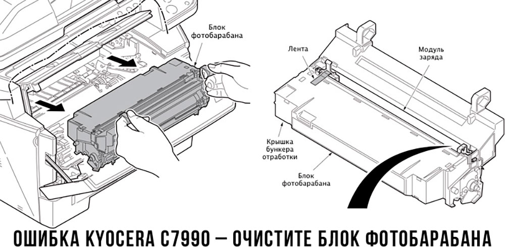
Чтобы потребитель мог наверняка определить проблему, рекомендуем использовать утилиту Kyocera Client Tool, которая идет в комплекте с драйверами принтера.
Ваше Имя:
Ваш вопрос:
Внимание: HTML не поддерживается! Используйте обычный текст.
Оценка:
Плохо
Хорошо
Введите код, указанный на картинке:


Все современные копировальные аппараты, мфу и принтеры Kyocera имеют возможность диагностировать все узлы устройства в режиме запуска и во время работы аппарата. По этому, если во время включения или во время работы произошел сбой, то техника Kyocera сможет сообщить о наличии ошибки.
В большинстве случаев у аппаратов Kyocera код ошибки отображается на дисплее, в остальных случаях тип ошибки зависит от последовательности и количества миганий индикаторов.
Если Ваш копировальный аппарат, МФУ или принтер Kyocera выдал на дисплее некий код, то узнать причину, описание возникновения ошибки, а так же в каком узле аппарата стоит искать проблему, Вы можете в этом разделе выбрав интересующую модель из списка.
Но диагностика не решит проблему сбоя аппарата, для этого лучше обратиться к профессиональным и опытным сервисным специалистам компании Kyomart! Позвоните нам по телефону
8 (343) 288-23-45 или отправьте запрос на электронную почту: sales@kyomart.ru , и мы обязательно свяжемся с Вами в кратчайшие сроки.
Processing with the fax software was disabled due to a hardware problem.
Abnormal detection of FAX control PWB incompatibility In the initial communication with the FAX control PWB, any normal communication command is not transmitted.
Defective FAX control PWB.
For data in which the MAC address is invalid.
Defective flash memory.
Defective engine PWB.
Defective main PWB.
Defective main PWB.
Detecting engine PWB EEPROM communication error.
Defective engine PWB.
Device damage of EEPROM.
Defective engine PWB.
A checksum error is detected in the main and engine backup memories for the billing counters.
Defective PWB.
Machine number of main and engine does not match.
A communication error is detected 10 times in succession.
JAM05 is detected twice.
A checksum error occurred with the program of the FAX control PWB.
Defective FAX control PWB.
The time is judged to go back based on the comparison of the RTC time and the current time or five years or more have passed.
Defective main PWB.
High-capacity data transfer between the FAX control PWB and the main PWB of the machine was not normally performed even if the data transfer was retried the specified times.
Defective FAX control PWB or main PWB.
The backup data is not retained for file system abnormality of flash memory of the FAX control PWB.
After cassette 1 is inserted, lift sensor does not turn on within 12 s. This error is detected four times successively.
Defective connector cable or poor contact in the connector.
Defective drive transmission system of the lift motor.
Defective lift motor.
Defective engine PWB.
After cassette 2 is inserted, PF lift sensor 1 does not turn on within 12 s. This error is detected four times successively.
Defective connector cable or poor contact in the connector.
Defective drive transmission system of the PF lift motor 1.
Defective PF lift motor 1.
Defective PF main PWB.
After cassette 3 is inserted, PF lift sensor 2 does not turn on within 12 s. This error is detected four times successively.
Defective connector cable or poor contact in the connector.
Defective drive transmission system of the PF lift motor 2.
Defective PF lift motor 2.
Defective PF main PWB.
A communication error is detected 10 times in succession.
Defective connector cable or poor contact in the connector.
Defective engine PWB.
Defective PF main PWB.
When writing the data, the write data and the read data is not continuously in agreement 5 times.
Device damage of EEPROM.
Stable OFF is detected for 1 s continuously after main motor stabilized.
Defective drive transmission system of the main motor.
Defective main motor.
Defective engine PWB.
The main motor is not stabilized within 2 s after driving starts.
Defective drive transmission system of the main motor.
Defective main motor.
Defective engine PWB.
The rated speed signal detected the stability OFF continuously for 1 s after the developer motor K stabilizes.
Defective drive transmission system.
Defective motor.
Defective PWB.
The rated speed signal detected the stability OFF continuously for 1 s after the developer motor YCM stabilizes.
Defective drive transmission system.
Defective motor.
Defective PWB.
Developer motor K is not stabilized within 2 s since the motor is activated.
Defective drive transmission system.
Defective motor.
Defective PWB.
Developer motor YCM is not stabilized within 2 s since the motor is activated.
Defective drive transmission system.
Defective motor.
Defective PWB.
The rated speed signal detected the stability OFF continuously for 1 s after the fuser motor stabilizes.
Defective drive transmission system.
Defective motor.
Defective PWB.
Fuser motor is not stabilized within 2 s since the motor is activated.
Defective drive transmission system.
Defective motor.
Defective PWB.
The rated speed signal detected the stability OFF continuously for 1 s after the conveying motor stabilizes.
Defective drive transmission system.
Defective motor.
Defective PWB.
Conveying motor is not stabilized within 2 s since the motor is activated.
Defective drive transmission system.
Defective motor.
Defective PWB.
When the PF drive motor is driven, error signal is detected continuously for 1 s.
Defective drive transmission system of the PF drive motor.
Defective PF drive motor.
Defective PF main PWB.
When the TC belt motor is driven, error signal is detected continuously for 1 s.
Defective drive transmission system of the PF drive motor.
Defective PF drive motor.
Defective PF main PWB.
The home position is not correct when the power is turned on or at the start of copying using the table.
Defective home position sensor.
Defective ISU motor.
Defective CCD PWB.
Defective engine PWB.
When input value at the time of exposure lamp illumination does not exceed the threshold value between 5 s.
Defective exposure lamp.
Defective CCD PWB.
Defective main PWB.
An error code is detected 3 times in succession.
Defective CCD PWB.
Defective main PWB.
The polygon motor is not stabilized within 10 s after driving starts.
Defective polygon motor.
Defective engine PWB.
The rated speed signal detected the stability OFF continuously for 1 s after the polygon motor (K) stabilizes.
Defective motor
Defective PWB.
The rated speed signal detected the stability OFF continuously for 1 s after the polygon motor (С) stabilizes.
Defective motor
Defective PWB.
The rated speed signal detected the stability OFF continuously for 1 s after the polygon motor (M) stabilizes.
Defective motor
Defective PWB.
The rated speed signal detected the stability OFF continuously for 1 s after the polygon motor (Y) stabilizes.
Defective motor
Defective PWB.
Stable OFF is detected for 1 s continuously after polygon motor stabilized.
Defective polygon motor.
Defective engine PWB.
Polygon motor (K) is not stabilized within 10 s since the motor is activated.
Defective motor.
Defective PWB.
Polygon motor (C) is not stabilized within 10 s since the motor is activated.
Defective motor.
Defective PWB.
Polygon motor (M) is not stabilized within 10 s since the motor is activated.
Defective motor.
Defective PWB.
Polygon motor (Y) is not stabilized within 10 s since the motor is activated.
Defective motor.
Defective PWB.
BD is not detected within 1 s after polygon motor stabilized.
Defective APC PWB.
Defective BD PWB.
Defective main PWB.
When the LSU cleaning motor is driven, an error signal is detected continuously for 1 s.
Defective drive transmission system.
Defective motor. Defective PWB.
Defective main PWB or engine PWB.
A communication error is detected 10 times in succession.
Defective PWB.
The detected temperature of fuser thermistor does not reach the specified temperature (ready indication temperature) after the fuser heater has been turned on continuously for 60 s in warming up. The fusing temperature at 7 seconds and 20 seconds since fuser temperature control has occurred differs by 43°C/109.4°F or less.
Deformed connector pin.
Defective triac.
Fuser thermostat triggered.
Broken fuser heater wire.
Defective engine PWB.
6020
6030
6050
Abnormally high fuser thermistor temperature Broken fuser thermistor wire Abnormally low fuser thermistor temperature
Defective triac.
The fuser thermistor detects a temperature higher than 230°C/446°F continuously for 40 ms. High fuser temperature signal detects a temperature of 255°C/491°F continuously for 40 ms.
Defective triac.
Shorted fuser thermistor.
Defective engine PWB.
A/D value of the fuser thermistor exceeds 251 bit continuously for 7 s during warming up.
Deformed connector pin.
Defective triac.
Defective fuser thermistor.
Defective engine PWB
As the stable temperature has reached the second time, the decrease in the fuser thermistor temperature of 60°C/140°F or greater is detected for one second.
Defective triac.
Defective fuser thermistor
Defective fuser heater.
Defective engine PWB.
The fuser temperature exceeds 200 °C/392 °F for 1 s.
Defective IH PWB.
Defective fuser thermistor.
Defective engine PWB.
Deformed connector pin.
Defective IH PWB.
Defective fuser thermistor.
Defective engine PWB.
The fuser temperature lower than 30 °C/86 °F is detected continuously for 1 s.
Defective fuser thermistor
Defective fuser heater.
Defective engine PWB.
Fuser thermistor 1 does not reach 50° C/122 °F even after20 s during warming up. The detected temperature of fuser thermistor1 does not reach the specified temperature (ready indication temperature) for 20 s in warming up after reaching 50° C/122 °F.
Deformed connector pin.
Fuser thermostat triggered.
Broken fuser heater wire.
Defective engine PWB.
The fuser temperature exceeds 240 °C/464 °F for 1 s
Deformed connector pin.
Fuser thermostat triggered.
Broken fuser heater wire.
Defective engine PWB.
During warming up a hearter, fuser thermistor 2 detects a temperature of 100 °C/212 °F or higher and, fuser thermistor 1 detects a temperature of 37 °C/99 °F or lower.
Deformed connector pin.
Fuser thermostat triggered.
Broken fuser heater wire.
Defective engine PWB.
The fuser temperature lower than 100 °C/212 °F is detected continuously for 1 s during printing. The fuser temperature lower than 50 °C/122 °F is detected continuously for 1 s during pre-heating.
Deformed connector pin.
Fuser thermostat triggered.
Broken fuser heater wire.
Defective engine PWB.
While fuser heater control is performed, the zero-cross signal is not input within 3 s.
Defective power source PWB or engine PWB.
Absence of the fuser unit is detected.
Different type of the fuser unit is installed.
The belt was detected to stop for 1 s continuously during motor remote is on.
Defective IH belt.
Defective IH PWB.
Defective engine PWB.
Defective PWB.
Defective PWB.
Defective PWB.
Defective PWB.
Absence of the developing unit K is detected.
Different type of the developing unit is installed.
Defective PWB.
Absence of the developing unit C is detected.
Different type of the developing unit is installed.
Defective PWB.
Absence of the developing unit M is detected.
Different type of the developing unit is installed.
Defective PWB.
Absence of the developing unit Y is detected.
Different type of the developing unit is installed.
Defective PWB.
Absence of the drum unit K is detected.
Different type of the drum unit is installed.
Defective PWB.
Absence of the drum unit C is detected.
Different type of the drum unit is installed.
Defective PWB.
Absence of the drum unit M is detected.
Different type of the drum unit is installed.
Defective PWB.
Absence of the drum unit Y is detected.
Different type of the drum unit is installed.
Defective PWB.
Absence of the transfer belt unit is detected.
Different type of the transfer belt unit is installed.
Defective PWB.
Defective PWB.
Defective PWB.
When ID sensor 2 detected CTD is 500 or less.
Defective PWB.
When ID sensor 2 detected CTD is 500 or less.
Defective PWB.
When ID sensor 2 detected CTD is 500 or less.
Defective PWB.
When ID sensor 2 detected CTD is 500 or less.
Defective PWB.
Color registration correction was failed.
Defective PWB.
The thermistor output value is 0.3 V or less.
Defective temperature sensor.
The thermistor output value is 3 V or more.
Defective temperature sensor.
No response is issued from the device in reading/writing for 5 ms or more and this problem is repeated five times successively. Mismatch of reading data from two locations occurs eight times successively. Mismatch between writing data and reading data occurs eight times successively.
Defective drum unit.
No response is issued from the device in reading/writing for 5 ms or more and this problem is repeated five times successively. Mismatch of reading data from two locations occurs eight times successively. Mismatch between writing data and reading data occurs eight times successively.
Defective developer unit.
No response is issued from the device in reading/writing for 5 ms or more and this problem is repeated five times successively. Mismatch of reading data from two locations occurs eight times successively. Mismatch between writing data and reading data occurs eight times successively.
Defective developing PWB.
When the tray elevation motor raises a tray, the ON status of the tray upper limit sensor is detected.
Defective tray upper limit sensor, paper surface sensor 1/2.
Defective DF main PWB.
The belt sensor does not turn on/off within specified time of the belt solenoid turning on.
Defective belt sensor.
Defective belt solenoid.
Defective DF main PWB.
The tray low limit sensor or paper surface sensor 1/2 cannot be detected to be on within 10 s since the tray elevation motor is activated.
Defective connector cable or poor contact in the connector.
The tray elevation motor malfunctions.
Defective tray lower limit sensor, paper surface sensor 1/2.
Defective DF main PWB.
Jam 7012 or 7023 is indicated.
The stapler is blocked with a staple.
The stapler is broken
Defective DF main PWB.
The adjustment sensor 2 does not turn on/off within specified time of the adjustment motor 2 turning on.
Defective adjustment sensor 2.
Defective adjustment motor 2.
Defective DF main PWB.
The adjustment sensor 1 does not turn on/off within specified time of the adjustment motor 1 turning on.
Defective adjustment sensor 1.
Defective adjustment motor 1.
The roller sensor does not turn on/off within specified time of the roller motor turning on.
Defective connector cable or poor contact in the connector.
Defective roller sensor.
Defective roller motor.
Defective DF main PWB.
The slide sensor does not turn on/off within specified time of the slide motor turning on.
Defective slide sensor.
Defective slide motor.
Defective DF main PWB.
Reading from or writing to EEPROM cannot be performed.
A communication error is detected 10 times in succession.
Defective DF main PWB.
Defective engine PWB.
A communication error is detected 10 times in succession.
Defective bridge PWB.
Defective engine PWB.
Defective DF main PWB.
Defective bridge PWB.
A communication error is detected 10 times in succession.
Defective DP main PWB.
Device damage of EEPROM.
Defective operation panel PWB.
Defective engine PWB.
Рассмотрим наиболее распространенные коды ошибок у популярных принтеров Kyocera FS-1020MFP, FS-1025MFP, FS-1030MFP, FS-1120MFP, FS-1125MFP, FS-1220MFP и прочих моделей, чтобы разобраться, какие неполадки можно устранить своими руками, а в каких случаях необходимо воспользоваться помощью специалистов.
Сброс ошибок у принтеров Kyocera своими руками
Под сбросом ошибок у принтеров Kyocera нужно понимать комплекс мероприятий, которые потенциально может осуществить опытный пользователь, чтобы восстановить работоспособность печатающих устройств без обращения в сервисный центр.
| Код ошибки | Причина | Решение проблемы |
| E-0001 | В принтере установлен совместимый картридж или чип расходника был поврежден. | Проблема решается несколькими способами:
1. Нажмите на несколько секунд кнопки «Режим» и «Сброс» 2. Установка оригинального картриджа 3. Замена поврежденного чипа 4. Прошивка принтера – затем в печатающее устройство можно будет установить любой картридж неограниченное количество раз |
| E-0002 | Регион используемого картриджа не соответствует характеристикам принтера. | Проблема решается несколькими способами: 1. Установка соответствующего региону принтера картриджа 2. Замена чипа 3. Прошивка принтера |
| E-0003 | Память печатающего устройства заполнена. | Распечатайте уже отсканированные документы или сбросьте операцию соответствующей кнопкой. |
| E-0007 | В картридже закончился тонер. | Замените картридж на новый оригинальный, совместимый или заправьте расходник. |
| E-0008 | Одна из крышек принтера не закрыта. | Захлопните заднюю и переднюю крышки принтера, ощутив характерный щелчок. |
| E-0009 | Лоток с отпечатками переполнен. | Извлеките распечатанные листы с бумагой, а затем возобновите печать кнопкой «Старт». |
| E-0012 | Память принтера заполнена. | Измените разрешение печати в меньшую сторону – до 600 dpi. |
| E-0014 | Установлена бумага такого формата, который принтер не поддерживает. | Замените бумагу листами совместимого формата. Иногда функционал принтера может быть ограничен на софтверном уровне.
Чтобы расширить диапазон форматов, мы рекомендуем обновить ПО печатающего устройства. |
| E-0015 | 1. У принтера отсутствует питание. 2. Сетевой кабель не подключен. 3. На персональном компьютере отсутствует драйвер. |
Проверьте целостность сетевого кабеля. Включите принтер.
При необходимости установите драйвер. |
| E-0018 | Выбранный файл отсутствует в очереди на печать | Сбросьте операцию, нажав на кнопку «Сброс». Затем выберите новый файл и продолжите печать. |
| E-0019 | Формат печати не поддерживается принтером | Сбросьте операцию, нажав на кнопку «Сброс». |
| J-0511 | Бумагу зажевало | Аккуратно извлеките остатки бумаги из корпуса принтера. |
| PF | Отсутствует бумага во входном лотке. | Установите бумагу во входной лоток и возобновите печать, нажав на кнопку «Старт». |
Устранение ошибок у принтеров Kyocera в сервисном центре
| Код ошибки | Возможная причина |
| 0030 | Неисправна PWB-плата. |
| 0100 | Неисправна Flash-память или плата PWB. |
| 0120 | Неисправна Flash-память. |
| 0190 | Неисправна Flash-память или плата PWB. |
| 0630 | Неисправна PWB-плата. |
| 2000 | 1. Неисправна PWB-плата
2. Неисправен соединительный кабель или нарушена целостность соединения контактов 3. Неисправен привод или его отдельные узлы. |
| 3100 | 1. Неисправен соединительный кабель или нарушена целостность соединения контактов 2. Неисправен датчик положения 3. Неисправен привод сканера 4. Неисправна PWB-плата |
| 3300 | 1. Неисправен соединительный кабель или нарушена целостность соединения контактов 2. Неисправен датчик CIS 3. Неисправна PWB-плата |
| 3500 | Неисправна PWB-плата. |
| 4000 | 1. Неисправен соединительный кабель или нарушена целостность соединения контактов
2. Неисправен привод 3. Неисправна PWB-плата |
| 4200 | 1. Неисправен соединительный кабель или нарушена целостность соединения контактов 2. Неисправна PWB-плата и отдельные компоненты |
| 6000 | 1. Неисправен соединительный кабель или нарушена целостность соединения контактов 2. Неисправен термостат 3. неисправен нагреватель фьюзера 4. неисправна PWB-плата и отдельные компоненты |
| 6020 | 1. Неисправна PWB-плата и отдельные компоненты 2. Выявлен дефект у термистора |
| 6030 | 1. Неисправен соединительный кабель или нарушена целостность соединения контактов 2. Выявлен дефект у термистора 3. Неисправен термостат 4. Неисправна PWB-плата и отдельные компоненты |
| 6400 | 1. Неисправен соединительный кабель или нарушена целостность соединения контактов 2. Неисправна PWB-плата и отдельные компоненты |
| F000 | Неисправна PWB-плата и отдельные компоненты |
| F020 | Неисправна PWB-плата |
| F040 | Неисправна PWB-плата |
| F05D | 1. Неисправно программное обеспечение привода 2. Неисправна PWB-плата и отдельные компоненты. |
Нажмите на звезду, чтобы оценить!
Прочитали: 1 091