
 Dislikes: 0
-
01-23-2021
#11

Junior Member
- Rep Power
- 0
Re: Kyocera Taskalfa 4500i Error Code C7460
-
01-23-2021
#12
Re: Kyocera Taskalfa 4500i Error Code C7460
I recommend that you get yourself a service manual and do some reading.
Is language the issue? If you aren’t technologically savvy enough to do this, I don’t see how I can help you through this text window.
I’ll go this far, here are some photos that you will find on page 639 of the service manual.:
Open Door.jpgUnion Connector.jpg
=^..^=
If you’d like a serious answer to your request:
1) demonstrate that you’ve read the manual
2) demonstrate that you made some attempt to fix it.
3) if you’re going to ask about jams include the jam code.
4) if you’re going to ask about an error code include the error code.
5) You are the person onsite. Only you can make observations.
blackcat: Master Of The Obvious =^..^=
-
01-23-2021
#13
Junior Member
- Rep Power
- 0
Re: Kyocera Taskalfa 4500i Error Code C7460
Originally Posted by blackcat4866
I recommend that you get yourself a service manual and do some reading.
Is language the issue? If you aren’t technologically savvy enough to do this, I don’t see how I can help you through this text window.
I’ll go this far, here are some photos that you will find on page 639 of the service manual.:
Open Door.jpgUnion Connector.jpg
=^..^=
Sir you
are the great, now i understand your question. No sir i don’t have any bent pins in the union connector. sir i attached the error occurred picture, guide me how to fix this error thanks.
error image1.jpgImage.jpg
-
01-23-2021
#14
Re: Kyocera Taskalfa 4500i Error Code C7460
This error points to the developer shutter sensor DEVSS. It’s a photosensor, and probably has toner in it.
This is how you remove the hopper:
Hopper.jpg
Here is the location of the sensor. You can clean it with canned air or a toothbrush.:
DEVSS.jpg
Remind me again: Why am I reading the manual to you? You can read, correct? =^..^=
If you’d like a serious answer to your request:
1) demonstrate that you’ve read the manual
2) demonstrate that you made some attempt to fix it.
3) if you’re going to ask about jams include the jam code.
4) if you’re going to ask about an error code include the error code.
5) You are the person onsite. Only you can make observations.
blackcat: Master Of The Obvious =^..^=
-
01-23-2021
#15
Junior Member
- Rep Power
- 0
Re: Kyocera Taskalfa 4500i Error Code C7460
Originally Posted by blackcat4866
This error points to the developer shutter sensor DEVSS. It’s a photosensor, and probably has toner in it.
This is how you remove the hopper:
Hopper.jpg
Here is the location of the sensor. You can clean it with canned air or a toothbrush.:
DEVSS.jpg
Remind me again: Why am I reading the manual to you? You can read, correct? =^..^=
yes the read your instruction correctly. after applying these instruction i will contact you soon and share the result
.
-
01-27-2021
#16
Senior Tech
100+ Posts
- Rep Power
- 29
Re: Kyocera Taskalfa 4500i Error Code C7460
poor fella.. id be just as clueless if i was expected to speak and function in Swahili
-
02-01-2021
#17
Re: Kyocera Taskalfa 4500i Error Code C7460
I have attached the section of the service manual that shows the developer locking mechanism in case there was continued confusion on the location of the DV Shutter.
-
02-13-2021
#18
Junior Member
- Rep Power
- 0
Re: Kyocera Taskalfa 4500i Error Code C7460
Originally Posted by blackcat4866
This error points to the developer shutter sensor DEVSS. It’s a photosensor, and probably has toner in it.
This is how you remove the hopper:
Hopper.jpg
Here is the location of the sensor. You can clean it with canned air or a toothbrush.:
DEVSS.jpg
Remind me again: Why am I reading the manual to you? You can read, correct? =^..^=
hey i clean
the hopper unit now i got a new error that is «C3300», please tell me what is this error and how to i fix it?.Thanks
i am waiting your response tell me about this as soon as possible.
-
02-13-2021
#19
Re: Kyocera Taskalfa 4500i Error Code C7460
3300 Optical system (AGC) error
One of the gains is FF or 00
during the CCD lamp AGC is
being processed.
LED lamp PWB1. To check the lamp, execute U061 CCD
(see page 1-3-149).2. Confirm that the wiring connector is
firmly connected and, if necessary,
connect the connector all the way in.
LED lamp PWB and ISC PWB (YC6)
CCD PWB (YC2) and ISC PWB (YC9)
ISC PWB (YC3) and Main PWB (YC11)3. If the wiring is disconnected, shorted or
grounded, replace the wiring.4. If the LED lamp won’t light, replace the
LED PWB and execut U411 (see page
1-3-149).
CCD PWB Replace the ISU and execute U411 (see
page 1-3-149).
ISC PWB Replace the ISC PWB and execute U411
(see page 1-3-149).
Main PWB Replace the main PWB (see page 1-5-58).
-
02-13-2021
#20
Junior Member
- Rep Power
- 0
Re: Kyocera Taskalfa 4500i Error Code C7460
Originally Posted by BillyCarpenter
3300 Optical system (AGC) error
One of the gains is FF or 00
during the CCD lamp AGC is
being processed.
LED lamp PWB1. To check the lamp, execute U061 CCD
(see page 1-3-149).2. Confirm that the wiring connector is
firmly connected and, if necessary,
connect the connector all the way in.
LED lamp PWB and ISC PWB (YC6)
CCD PWB (YC2) and ISC PWB (YC9)
ISC PWB (YC3) and Main PWB (YC11)3. If the wiring is disconnected, shorted or
grounded, replace the wiring.4. If the LED lamp won�t light, replace the
LED PWB and execut U411 (see page
1-3-149).
CCD PWB Replace the ISU and execute U411 (see
page 1-3-149).
ISC PWB Replace the ISC PWB and execute U411
(see page 1-3-149).
Main PWB Replace the main PWB (see page 1-5-58).Hey please share the book that you mention and also guide me step by step how to fix it.
Thanks.


 are the great, now i understand your question. No sir i don’t
  .
.


 the hopper unit now i got a new
  error that is
  «C3300», please tell me what is this error and how to i fix it?.Thanks
Tags for this Thread
Bookmarks
Bookmarks
Posting Permissions

- You may not post new threads
- You may not post replies
- You may not post attachments
- You may not edit your posts
- BB code is On
- Smilies are On
- [IMG] code is On
- [VIDEO] code is On
- HTML code is Off
Forum Rules
- Code: 0030
- Description: FAX control PWB system error
Processing with the fax software was disabled due to a hardware problem. - Causes: Defective FAX control PWB.
- Remedy: Replace the fax control PWB and check for correct operation.
- Code: 0060
- Description: Illegal engine PWB type
The engine main PWB and the engine sub PWB are incompatible. - Causes: Defective engine sub PWB.
- Remedy: Replace the engine PWB and check for correct operation.
- Code: 0070
- Description: FAX control PWB incompatible detection error
Abnormal detection of FAX control PWB incompatibility In the initial communication with the FAX control PWB, any normal communication command is not transmitted. - Causes: Defective FAX software.
Defective FAX control PWB. - Remedy: Defective FAX software. Install the fax software.
Defective FAX control PWB. Replace the fax control PWB and check for correct operation.
- Code: 0100
- Description: Backup memory device error
- Causes: Defective flash memory.
Defective main PWB. - Remedy: Defective flash memory. Replace the main PWB and check for correct operation.
Defective main PWB. Replace the main PWB and check for correct operation.
- Code: 0120
- Description: MAC address data error
For data in which the MAC address is invalid. - Causes: Defective flash memory
Defective engine PWB. - Remedy: Defective flash memory. Replace the main PWB and check for correct operation.e 1-5-46).
- Code: 0150
- Description: Backup memory read/write error (engine PWB)
No response is issued from the device in reading/writing for 5 ms or more and this problem is repeated 5 times successively. Mismatch of reading data from 2 locations occurs 8 times successively. Mismatch between writing data and reading data occurs 8 times successively. - Causes: Improper installation EEPROM.
Device damage of EEPROM. - Remedy: Improper installation EEPROM. Check the installation of the EEPROM and remedy if necessary.
Defective engine PWB. Replace the engine PWB and check for correct operation.
Device damage of EEPROM. Contact the Service Administrative Division.
- Code: 0160
- Description: Backup memory data error (engine PWB)
Reading data from EEPROM is abnormal. - Causes: Data damage of EEPROM.
- Remedy: Contact the Service Administrative Division.
- Code: 0170
- Description: Billing counting error
A checksum error is detected in the main and engine backup memories for the billing counters. - Causes: Data damage of EEPROM.
Defective PWB. - Remedy: Data damage of EEPROM. Contact the Service Administrative Division.
Defective PWB. Replace the main PWB or the engine PWB and check for correct operation.
- Code: 0180
- Description: Machine number mismatch
Machine number of main and engine does not match. - Causes: Data damage of EEPROM.
- Remedy: Contact the Service Administrative Division.
- Code: 0620
- Description: FAX image DIMM error
DIMM is not installed correctly. DIMM cannot be accessed. - Causes: DIMM installed incorrectly.
Defective main PWB. - Remedy: DIMM installed incorrectly. Check if the DIMM is inserted into the socket on the main PWB correctly.
Defective main PWB. Replace the main PWB and check for correct operation.
- Code: 0630
- Description: DMA error
DMA transmission of image data does not complete within the specified period of time. - Causes: Poor contact in the connector terminals.
Defective main PWB. - Remedy: Poor contact in the connector terminals. Check the connection the signal cable for CIS and the main PWB, and the continuity across the connector terminals. Repair or replace if necessary.
Defective main PWB. Replace the main PWB and check for correct operation.
- Code: 0640
- Description: Hard disk error
The hard disk cannot be accessed. - Causes: Defective hard disk.
Defective main PWB. - Remedy: Defective connector cable or poor contact in the connector. Reinsert the connector. Also check for continuity within the connector cable. If none, replace the cable.
Defective hard disk. Run U024 (HDD formatting) without turning the power off to initialize the hard disk. Replace the hard disk drive and check for correct operation if the problem is still detected after initialization.
Defective main PWB. Replace the main PWB and check for correct operation.
- Code: 0650
- Description: FAX image DIMM check error
Improper DIMM is installed. - Causes: DIMM installed incorrectly.
Defective main PWB. - Remedy: DIMM installed incorrectly. Check if the DIMM is inserted into the socket on the main PWB correctly.
DIMM of another machine is installed. Perform maintenance mode U671 (RECOVERY FAX DIMM).
Defective main PWB. Replace the main PWB and check for correct operation.
- Code: 0800
- Description: Image processing error
JAM010X is detected twice. - Causes: Defective main PWB.
- Remedy: Replace the main PWB and check for correct operation.
- Code: 0830
- Description: FAX control PWB flash program area checksum error
A checksum error occurred with the program of the FAX control PWB. - Causes: Defective FAX software.
Defective FAX control PWB. - Remedy: Defective FAX software. Install the fax software.
Defective FAX control PWB. Replace the fax control PWB and check for correct operation.
- Code: 0840
- Description: Faults of RTC
The time is judged to go back based on the comparison of the RTC time and the current time or five years or more have passed. - Causes: The battery is disconnected from the main PWB
Defective main PWB. - Remedy: The battery is disconnected from the main PWB. Check visually and remedy if necessary
Defective main PWB. Replace the main PWB and check for correct operation.
- Code: 0870
- Description: FAX control PWB to main PWB high capacity data transfer error
High-capacity data transfer between the FAX control PWB and the main PWB of the machine was not normally performed even if the data transfer was retried the specified times - Causes: Improper installation FAX control PWB.
Defective FAX control PWB or main PWB. - Remedy: Improper installation FAX control PWB. Reinstall the FAX control PWB.
Defective FAX control PWB or main PWB. Replace the FAX control PWB or main PWB and check for correct operation.
- Code: 0920
- Description: Fax file system error
The backup data is not retained for file system abnormality of flash memory of the FAX control PWB. - Causes: Defective FAX control PWB.
- Remedy: Replace the fax control PWB and check for correct operation.
- Code: 0970
- Description: 12 V power down detect Power is disconnected during sleeping.
- Causes: Defective power source PWB.
- Remedy: Replace the power source PWB and check for correct operation.
- Code: 0980
- Description: 24 V power down detect 24V disconnection signal is detected for 1 s and 12V disconnection signal is not detected.
- Causes: Defective power source PWB.
- Remedy: Replace the power source PWB and check for correct operation.
- Code: 1000
- Description: MP lift motor error
After the MP lift motor is driven, the ON status of MP lift sensors 1 and 2 cannot be detected for 3 s. - Causes: Defective MP plate elevation mechanism.
Defective connector cable or poor contact in the connector.
Defective drive transmission system of motor.
Defective MP lift motor.
Defective engine PWB. - Remedy: Defective MP plate elevation mechanism. Check to see if the MP plate can move smoothly and repair it if any problem is found.
Defective connector cable or poor contact in the connector. Reinsert the connector. Also check for continuity within the connector cable. If none, replace the cable. MP lift motor and relay PWB (YC3) Relay PWB (YC12) and feed PWB 1 (YC17) Feed PWB 1 (YC1) and engine PWB (YC6)
Defective drive transmission system of motor. Check if the gears rotate smoothly. If not, grease the bushes and gears. Check for broken gears and replace if any.
Defective MP lift motor. Replace the MP lift motor.
Defective engine PWB. Replace the engine PWB and check for correct operation.
- Code: 1010
- Description: Lift motor 1 error
After cassette 1 is inserted, lift sensor 1 does not turn on within 12 s. This error is detected 5 times successively. The lock signal of the motor is detected continuously for 1 s. This error is detected 5 times successively. - Causes: Defective bottom plate elevation mechanism in the cassette.
Defective connector cable or poor contact in the connector.
Defective drive transmission system of motor.
Defective lift motor 1.
Defective engine PWB. - Remedy: Defective bottom plate elevation mechanism in the cassette. Check to see if the bottom plate can move smoothly and repair it if any problem is found.
Defective connector cable or poor contact in the connector. Reinsert the connector. Also check for continuity within the connector cable. If none, replace the cable. Lift motor 1 and feed PWB 2 (YC3) Feed PWB 2 (YC1) and engine PWB (YC4)
Defective drive transmission system of motor. Check if the gears rotate smoothly. If not, grease the bushes and gears. Check for broken gears and replace if any.
Defective lift motor 1. Replace the lift motor 1.
Defective engine PWB. Replace the engine PWB and check for correct operation.
- Code: 1020
- Description: Lift motor 2 error
After cassette 2 is inserted, lift sensor 2 does not turn on within 12 s. This error is detected 5 times successively. The lock signal of the motor is detected continuously for 1 s. This error is detected 5 times successively. - Causes: Defective bottom plate elevation mechanism in the cassette.
Defective connector cable or poor contact in the connector.
Defective drive transmission system of motor.
Defective lift motor 2.
Defective engine PWB. - Remedy: Defective bottom plate elevation mechanism in the cassette. Check to see if the bottom plate can move smoothly and repair it if any problem is found.
Defective connector cable or poor contact in the connector. Reinsert the connector. Also check for continuity within the connector cable. If none, replace the cable. Lift motor 2 and feed PWB 2 (YC3) Feed PWB 2 (YC1) and engine PWB (YC4)
Defective drive transmission system of motor. Check if the gears rotate smoothly. If not, grease the bushes and gears. Check for broken gears and replace if any.
Defective lift motor 2. Replace the lift motor 2.
Defective engine PWB. Replace the engine PWB and check for correct operation.
- Code: 1050
- Description: SM lift motor error (side multi tray)
After cassette 5 is inserted, SM lift sensor does not turn on within 12 s. This error is detected 5 times successively. (Time to detect is 2 seconds at the second time and later.) During driving the motor, the lift overcurrent protective monitor signal is detected for 1 s or more 5 times successively. However, the first 1 s after motor is turned on is excluded from detection. - Causes: Defective bottom plate elevation mechanism in the cassette.
Defective connector cable or poor contact in the connector.
Defective drive transmission system of motor
Defective SM lift motor.
Defective SM main PWB. - Remedy: Defective bottom plate elevation mechanism in the cassette. Check to see if the bottom plate can move smoothly and repair it if any problem is found.
Defective connector cable or poor contact in the connector. Reinsert the connector. Also check for continuity within the connector cable. If none, replace the cable. SM lift motor and SM main PWB (YC5)
Defective drive transmission system of motor. Check if the gears rotate smoothly. If not, grease the bushes and gears. Check for broken gears and replace if any.
Defective SM lift motor. Replace the SM lift motor.
Defective SM main PWB. Replace the SM main PWB (Refer to the service manual for the paper feeder).
- Code: 1060
- Description: PF lift motor 1 error (side paper feeder)
After cassette 6 is inserted, PF lift sensor 1 does not turn on within 12 s. This error is detected 5 times successively. (Time to detect is 2 seconds at the second time and later.) During driving the motor, the lift overcurrent protective monitor signal is detected for 1 s or more 5 times successively. However, the first 1 s after motor is turned on is excluded from detection. : The lift over-current protection monitor signal has been detected for 200ms or longer where LFC is installed. - Causes: Defective bottom plate elevation mechanism in the cassette.
Defective connector cable or poor contact in the connector.
Defective drive transmission system of motor.
Defective PF lift motor 1.
Defective PF main PWB. - Remedy: Defective bottom plate elevation mechanism in the cassette. Check to see if the bottom plate can move smoothly and repair it if any problem is found.
Defective connector cable or poor contact in the connector. Reinsert the connector. Also check for continuity within the connector cable. If none, replace the cable. PF lift motor 1 and PF main PWB (YC7)
Defective drive transmission system of motor. Check if the gears rotate smoothly. If not, grease the bushes and gears. Check for broken gears and replace if any.
Defective PF lift motor 1. Replace the PF lift motor 1.
Defective PF main PWB. Replace the PF main PWB (Refer to the service manual for the paper feeder).
- Code: 1070
- Description: PF lift motor 2 error (side paper feeder)
After cassette 7 is inserted, PF lift sensor 2 does not turn on within 12 s. This error is detected 5 times successively. (Time to detect is 2 seconds at the second time and later.) During driving the motor, the lift overcurrent protective monitor signal is detected for 1 s or more 5 times successively. However, the first 1 s after motor is turned on is excluded from detection. : The lift over-current protection monitor signal has been detected for 200ms or longer where LFC is installed. - Causes: Defective bottom plate elevation mechanism in the cassette.
Defective connector cable or poor contact in the connector.
Defective drive transmission system of motor.
Defective PF lift motor 2.
Defective PF main PWB. - Remedy: Defective bottom plate elevation mechanism in the cassette. Check to see if the bottom plate can move smoothly and repair it if any problem is found.
Defective connector cable or poor contact in the connector. Reinsert the connector. Also check for continuity within the connector cable. If none, replace the cable. PF lift motor 2 and PF main PWB (YC7)
Defective drive transmission system of motor. Check if the gears rotate smoothly. If not, grease the bushes and gears. Check for broken gears and replace if any.
Defective PF lift motor 2. Replace the PF lift motor 2.
Defective PF main PWB. Replace the PF main PWB (Refer to the service manual for the paper feeder).
- Code: 1100
- Description: PF lift motor 1 error
After cassette 3 is inserted, PF lift sensor 1 does not turn on within 23 s. This error is detected 5 times successively. (Time to detect is 2 seconds at the second time and later.) During driving the motor, the lift overcurrent protective monitor signal is detected for 200 ms or more 5 times successively. However, the first 1 s after PF lift motor 1 is turned on is excluded from detection. - Causes: Defective connector cable or poor contact in the connector.
Defective drive transmission system of motor.
Defective PF lift motor 1.
Defective PF main PWB. - Remedy: Defective connector cable or poor contact in the connector. Reinsert the connector. Also check for continuity within the connector cable. If none, replace the cable. PF lift motor 1 and PF main PWB (YC7)
Defective drive transmission system of motor. Check if the gears rotate smoothly. If not, grease the bushes and gears. Check for broken gears and replace if any.
Defective PF lift motor 1. Replace the PF lift motor 1.
Defective PF main PWB. Replace the PF main PWB.
- Code: 1110
- Description: PF lift motor 2 error
After cassette 4 is inserted, PF lift sensor 2 does not turn on within 23 s. This error is detected 5 times successively. (Time to detect is 2 seconds at the second time and later.) During driving the motor, the lift overcurrent protective monitor signal is detected for 200 ms or more 5 times successively. However, the first 1 s after PF lift motor 2 is turned on is excluded from detection. - Causes: Defective connector cable or poor contact in the connector.
Defective drive transmission system of motor.
Defective PF lift motor 2.
Defective PF main PWB. - Remedy: Defective connector cable or poor contact in the connector. Reinsert the connector. Also check for continuity within the connector cable. If none, replace the cable. PF lift motor 2 and PF main PWB (YC7)
Defective drive transmission system of motor. Check if the gears rotate smoothly. If not, grease the bushes and gears. Check for broken gears and replace if any.
Defective PF lift motor 2. Replace the PF lift motor 2.
Defective PF main PWB. Replace the PF main PWB.
- Code: 1140
- Description: SD lift motor error (side deck)
After cassette 5 is inserted, SD lift sensor does not turn on within 30 s. The lock signal of the motor is detected continuously for 200 ms. - Causes: Defective connector cable or poor contact in the connector.
Defective drive transmission system of motor.
Defective SD lift motor.
Defective SD main PWB. - Remedy: Defective connector cable or poor contact in the connector. Reinsert the connector. Also check for continuity within the connector cable. If none, replace the cable. SD lift motor and SD main PWB (YC8)
Defective drive transmission system of motor. Check if the gears rotate smoothly. If not, grease the bushes and gears. Check for broken gears and replace if any.
Defective SD lift motor. Replace the SD lift motor.
Defective SD main PWB. Replace the SD main PWB (Refer to the service manual for the paper feeder).
- Code: 1250
- Description: SM multi feed sensor communication error (side multi tray)
A communication error is detected 3 times in succession. - Causes: Improper installation side multi tray.
Defective connector cable or poor contact in the connector.
Defective engine PWB.
Defective SM main PWB. - Remedy: Improper installation side multi tray. Follow installation instruction carefully again.
Defective connector cable or poor contact in the connector. Reinsert the connector. Also check for continuity within the connector cable. If none, replace the cable. SM main PWB (YC1) and engine PWB (YC19)
Defective engine PWB. Replace the engine PWB and check for correct operation.
Defective SM main PWB. Replace the SM main PWB (Refer to the service manual for the paper feeder).
- Code: 1350
- Description: SM multi feed sensor error (side multi tray)
The SM multi feed sensor has detected multi feeding 5 times successively. - Causes: Defective connector cable or poor contact in the connector.
Defective SM multi feed sensor.
Defective SM main PWB. - Remedy: Defective connector cable or poor contact in the connector. Reinsert the connector. Also check for continuity within the connector cable. If none, replace the cable. SM multi feed sensor and SM main PWB (YC11)
Defective SM multi feed sensor. Replace the SM multi feed sensor.
Defective SM main PWB. Replace the SM main PWB (Refer to the service manual for the paper feeder).
- Code: 1410
- Description: BR decurler motor error
The BR decurler sensor won’t turn on or off when it was activated for 400 steps (3 times in succession). - Causes: Defective connector cable or poor contact in the connector.
Defective drive transmission system of motor.
Defective BR decurler motor.
Defective BR main PWB.
Defective engine PWB. - Remedy: Defective connector cable or poor contact in the connector. Reinsert the connector. Also check for continuity within the connector cable. If none, replace the cable. BR decurler motor and BR main PWB (YC5) BR main PWB (YC2) and engine PWB (YC20)
Defective drive transmission system of motor. Check if the gears rotate smoothly. If not, grease the bushes and gears. Check for broken gears and replace if any.
Defective BR decurler motor. Replace the BR decurler motor.
Defective BR main PWB. Replace the BR main PWB and check for correct operation.
Defective engine PWB. Replace the engine PWB and check for correct operation.
- Code: 1450
- Description: SM multi feed sensor backup error (side multi tray)
When writing the data, read and write data does not match 3 times in succession. Deleting a block has failed three times in a row. Writing won’t complete in 200 ms after writing has commenced. - Causes: Defective connector cable or poor contact in the connector.
Defective SM multi feed sensor.
Defective SM main PWB. - Remedy: Defective connector cable or poor contact in the connector. Reinsert the connector. Also check for continuity within the connector cable. If none, replace the cable. SM multi feed sensor and SM main PWB (YC11)
Defective SM multi feed sensor. Replace the SM multi feed sensor.
Defective SM main PWB. Replace the SM main PWB (Refer to the service manual for the paper feeder).
- Code: 1720
- Description: Paper feeder incompatible detection error
The paper feeder has been installed with a device to which it is incompatible. - Causes: The paper feeder is installed with a device to which it is incompatible.
- Remedy: The paper feeder must be installed with the devices to which it is compatible.
- Code: 1800
- Description: Paper feeder communication error
A communication error from paper feeder is detected 10 times in succession. - Causes: Improper installation paper feeder.
Defective connector cable or poor contact in the connector.
Defective engine PWB.
Defective PF main PWB. - Remedy: Improper installation paper feeder. Follow installation instruction carefully again.
Defective connector cable or poor contact in the connector. Reinsert the connector. Also check for continuity within the connector cable. If none, replace the cable. PF main PWB (YC13) and engine PWB (YC19)
Defective engine PWB. Replace the engine PWB and check for correct operation.
Defective PF main PWB. Replace the PF main PWB.
- Code: 1810
- Description: Side multi tray communication error
A communication error from paper feeder is detected 10 times in succession. - Causes: Improper installation side multi tray.
Defective connector cable or poor contact in the connector.
Defective engine PWB.
Defective SM main PWB. - Remedy: Improper installation side multi tray. Follow installation instruction carefully again.
Defective connector cable or poor contact in the connector. Reinsert the connector. Also check for continuity within the connector cable. If none, replace the cable. SM main PWB (YC1) and engine PWB (YC19)
Defective engine PWB. Replace the engine PWB and check for correct operation.
Defective SM main PWB. Replace the SM main PWB (Refer to the service manual for the paper feeder).
- Code: 1820
- Description: Side paper feeder communication error
A communication error from paper feeder is detected 10 times in succession. - Causes: Improper installation side paper feeder.
Defective connector cable or poor contact in the connector.
Defective engine PWB.
Defective SM main PWB.
Defective PF main PWB. - Remedy: Improper installation side paper feeder. Follow installation instruction carefully again.
Defective connector cable or poor contact in the connector. Reinsert the connector. Also check for continuity within the connector cable. If none, replace the cable. PF main PWB (YC13) and SM main PWB (YC4) SM main PWB (YC1) and engine PWB (YC19)
Defective engine PWB. Replace the engine PWB and check for correct operation.
Defective SM main PWB. Replace the SM main PWB (Refer to the service manual for the paper feeder).
Defective PF main PWB. Replace the PF main PWB (Refer to the service manual for the paper feeder).
- Code: 1900
- Description: Paper feeder EEPROM error
When writing the data, read and write data does not match 3 times in succession. - Causes: Defective PF main PWB.
Device damage of EEPROM. - Remedy: Defective PF main PWB. Replace the PF main PWB (Refer to the service manual for the paper feeder).
Device damage of EEPROM. Contact the Service Administrative Division.
- Code: 1910
- Description: Side multi tray EEPROM error
When writing the data, read and write data does not match 3 times in succession. - Causes: Defective SM main PWB.
Device damage of EEPROM. - Remedy: Defective SM main PWB. Replace the SM main PWB (Refer to the service manual for the paper feeder).
Device damage of EEPROM. Contact the Service Administrative Division.
- Code: 1920
- Description: Side paper feeder EEPROM error
When writing the data, read and write data does not match 3 times in succession. - Causes: Defective PF main PWB.
Device damage of EEPROM. - Remedy: Defective PF main PWB. Replace the PF main PWB (Refer to the service manual for the paper feeder).
Device damage of EEPROM. Contact the Service Administrative Division.
- Code: 2101
- Description: Developer motor error
After developer motor is driven, the ready signal does not turn to L within 2 s. After developer motor is stabilized, the ready signal is at the H level for 1 s continuously. - Causes: Defective connector cable or poor contact in the connector.
Defective drive transmission system of motor.
Defective developer motor.
Defective engine PWB. - Remedy: Defective connector cable or poor contact in the connector. Reinsert the connector. Also check for continuity within the connector cable. If none, replace the cable. Developer motor and feed PWB 1 (YC8) Feed PWB 1 (YC2) and engine PWB (YC5)
Defective drive transmission system of motor. Check if the gears rotate smoothly. If not, grease the bushes and gears. Check for broken gears and replace if any.
Defective developer motor. Replace the developer motor.
Defective engine PWB. Replace the engine PWB and check for correct operation.
- Code: 2201
- Description: Drum motor steady-state error
The ready signal won’t turn to L in 2 seconds after the drum motor is started. After drum motor is stabilized, the ready signal is at the H level for 5 s continuously. The device won’t engage in ready state in 60 minutes after warming-up has began. - Causes: Defective connector cable or poor contact in the connector.
Defective drive transmission system of motor.
Defective drum motor.
Defective engine PWB. - Remedy: Defective connector cable or poor contact in the connector. Reinsert the connector. Also check for continuity within the connector cable. If none, replace the cable. Drum motor and feed PWB 1 (YC9) Feed PWB 1 (YC2) and engine PWB (YC5)
Defective drive transmission system of motor. Check if the gears rotate smoothly. If not, grease the bushes and gears. Check for broken gears and replace if any.
Defective drum motor. Replace the drum motor.
Defective engine PWB. Replace the engine PWB and check for correct operation.
- Code: 2300
- Description: Fuser motor error
After fuser motor is driven, the ready signal does not turn to L within 2 s. After fuser motor is stabilized, the ready signal is at the H level for 1 s continuously. - Causes: Defective connector cable or poor contact in the connector.
Defective drive transmission system of motor.
Defective fuser motor.
Defective engine PWB. - Remedy: Defective connector cable or poor contact in the connector. Reinsert the connector. Also check for continuity within the connector cable. If none, replace the cable. Fuser motor and feed PWB 1 (YC18) Feed PWB 1 (YC1) and engine PWB (YC6)
Defective drive transmission system of motor. Check if the gears rotate smoothly. If not, grease the bushes and gears. Check for broken gears and replace if any.
Defective fuser motor. Replace the fuser motor.
Defective engine PWB. Replace the engine PWB and check for correct operation.
- Code: 2500
- Description: Paper feed motor error
After paper feed motor is driven, the ready signal does not turn to L within 2 s. After paper feed motor is stabilized, the ready signal is at the H level for 1 s continuously. - Causes: Defective connector cable or poor contact in the connector.
Defective drive transmission system of motor.
Defective paper feed motor.
Defective engine PWB. - Remedy: Defective connector cable or poor contact in the connector. Reinsert the connector. Also check for continuity within the connector cable. If none, replace the cable. Paper feed motor and feed PWB 2 (YC2) Feed PWB 2 (YC1) and engine PWB (YC4)
Defective drive transmission system of motor. Check if the gears rotate smoothly. If not, grease the bushes and gears. Check for broken gears and replace if any.
Defective paper feed motor. Replace the paper feed motor.
Defective engine PWB. Replace the engine PWB and check for correct operation.
- Code: 2550
- Description: Transfer motor error
After transfer motor is driven, the ready signal does not turn to L within 2 s. After transfer motor is stabilized, the ready signal is at the H level for 1 s continuously. - Causes: Defective connector cable or poor contact in the connector.
Defective drive transmission system of motor.
Defective fuser motor.
Defective engine PWB. - Remedy: Defective connector cable or poor contact in the connector. Reinsert the connector. Also check for continuity within the connector cable. If none, replace the cable. Transfer motor and relay PWB (YC6) Relay PWB (YC5) and feed PWB 1 (YC13) Feed PWB 1 (YC1) and engine PWB (YC6)
Defective drive transmission system of motor. Check if the gears rotate smoothly. If not, grease the bushes and gears. Check for broken gears and replace if any.
Defective fuser motor. Replace the fuser motor.
Defective engine PWB. Replace the engine PWB and check for correct operation.
- Code: 2600
- Description: PF paper feed motor error
After PF paper feed motor is driven, the ready signal does not turn to L within 2 s. - Causes: Defective connector cable or poor contact in the connector.
Defective drive transmission system of motor.
Defective PF paper feed motor.
Defective PF main PWB. - Remedy: Defective connector cable or poor contact in the connector. Reinsert the connector. Also check for continuity within the connector cable. If none, replace the cable. PF paper feed motor and PF main PWB (YC16)
Defective drive transmission system of motor. Check if the gears rotate smoothly. If not, grease the bushes and gears. Check for broken gears and replace if any.
Defective PF paper feed motor. Replace the PF paper feed motor.
Defective PF main PWB. Replace the PF main PWB.
- Code: 2610
- Description: PF paper feed motor error (paper feeder)
After PF paper feed motor is driven, the ready signal does not turn to L within 2 s. - Causes: Defective connector cable or poor contact in the connector.
Defective drive transmission system of motor.
Defective PF paper feed motor.
Defective PF main PWB. - Remedy: Defective connector cable or poor contact in the connector. Reinsert the connector. Also check for continuity within the connector cable. If none, replace the cable. PF paper feed motor and PF main PWB (YC16)
Defective drive transmission system of motor. Check if the gears rotate smoothly. If not, grease the bushes and gears. Check for broken gears and replace if any.
Defective PF paper feed motor. Replace the PF paper feed motor.
Defective PF main PWB. Replace the PF main PWB (Refer to the service manual for the paper feeder).
- Code: 2640
- Description: SD paper feed motor error (side deck)
After SD paper feed motor is driven, the ready signal does not turn to L within 2 s. - Causes: Defective connector cable or poor contact in the connector.
Defective drive transmission system of motor.
Defective SD paper feed motor.
Defective SD main PWB. - Remedy: Defective connector cable or poor contact in the connector. Reinsert the connector. Also check for continuity within the connector cable. If none, replace the cable. SD paper feed motor and SD main PWB (YC16)
Defective drive transmission system of motor. Check if the gears rotate smoothly. If not, grease the bushes and gears. Check for broken gears and replace if any.
Defective SD paper feed motor. Replace the SD paper feed motor.
Defective SD main PWB. Replace the SD main PWB (Refer to the service manual for the paper feeder).
- Code: 2650
- Description: SM paper feed motor error (side multi tray)
After SM paper feed motor is driven, the ready signal does not turn to L within 2 s. - Causes: Defective connector cable or poor contact in the connector.
Defective drive transmission system of motor.
Defective SM paper feed motor.
Defective SM main PWB. - Remedy: Defective connector cable or poor contact in the connector. Reinsert the connector. Also check for continuity within the connector cable. If none, replace the cable. SM paper feed motor and SM main PWB (YC5)
Defective drive transmission system of motor. Check if the gears rotate smoothly. If not, grease the bushes and gears. Check for broken gears and replace if any.
Defective SM paper feed motor. Replace the SM paper feed motor.
Defective SM main PWB. Replace the SM main PWB (Refer to the service manual for the paper feeder).
- Code: 2660
- Description: PF paper feed motor error (side large capacity feeder)
After PF paper feed motor is driven, the ready signal does not turn to L within 2 s. - Causes: Defective connector cable or poor contact in the connector.
Defective drive transmission system of motor.
Defective PF paper feed motor.
Defective PF main PWB. - Remedy: Defective connector cable or poor contact in the connector. Reinsert the connector. Also check for continuity within the connector cable. If none, replace the cable. PF paper feed motor and PF main PWB (YC16)
Defective drive transmission system of motor. Check if the gears rotate smoothly. If not, grease the bushes and gears. Check for broken gears and replace if any.
Defective PF paper feed motor. Replace the PF paper feed motor.
Defective PF main PWB. Replace the PF main PWB (Refer to the service manual for the paper feeder).
- Code: 2670
- Description: PF paper feed motor error (side paper feeder)
After PF paper feed motor is driven, the ready signal does not turn to L within 2 s. - Causes: Defective connector cable or poor contact in the connector.
Defective drive transmission system of motor.
Defective PF paper feed motor.
Defective PF main PWB. - Remedy: Defective connector cable or poor contact in the connector. Reinsert the connector. Also check for continuity within the connector cable. If none, replace the cable. PF paper feed motor and PF main PWB (YC16)
Defective drive transmission system of motor. Check if the gears rotate smoothly. If not, grease the bushes and gears. Check for broken gears and replace if any.
Defective PF paper feed motor. Replace the PF paper feed motor.
Defective PF main PWB. Replace the PF main PWB (Refer to the service manual for the paper feeder).
- Code: 3100
- Description: Scanner carriage error
The home position is not correct when the power is turned on or at the start of copying using the table. - Causes: Defective connector cable or poor contact in the connector.
Defective home position sensor.
Defective scanner motor.
Defective ISC PWB.
Defective main PWB. - Remedy: Defective connector cable or poor contact in the connector. Reinsert the connector. Also check for continuity within the connector cable. If none, replace the cable. Home position sensor and ISC PWB (YC8) Scanner motor and ISC PWB (YC5) ISC PWB (YC3) and main PWB (YC11)
Defective home position sensor. Replace the home position sensor.
Defective scanner motor. Replace the scanner motor.
Defective ISC PWB. Replace the ISC PWB and check for correct operation.
The scanner mirror frame is being locked after setup. Check whether the scanner mirror frame has been unlocked and unlock if necessary.
Defective main PWB. Replace the main PWB and check for correct operation.
- Code: 3200
- Description: Exposure lamp error
When input value at the time of LED lamp PWB illumination does not exceed the threshold value between 5 s. - Causes: Defective connector cable or poor contact in the connector.
Defective LED lamp PWB.
Defective ISC PWB.
Defective main PWB. - Remedy: Defective connector cable or poor contact in the connector. Reinsert the connector. Also check for continuity within the connector cable. If none, replace the cable. LED lamp PWB and ISC PWB (YC6) CCD PWB (YC2) and ISC PWB (YC9) ISC PWB (YC3) and main PWB (YC11)
Defective LED lamp PWB. Replace the LED lamp PWB and check for correct operation.
Defective ISC PWB. Replace the ISC PWB and check for correct operation.
Defective CCD PWB. Replace the ISU and check for correct operation.
Defective main PWB. Replace the main PWB and check for correct operation.
- Code: 3210
- Description: CIS lamp error
When input value at the time of CIS illumination does not exceed the threshold value between 5 s. - Causes: Defective connector cable or poor contact in the connector.
Defective CIS.
Defective DPSHD PWB.
Defective DP relay PWB. - Remedy: Defective connector cable or poor contact in the connector. Reinsert the connector. Also check for continuity within the connector cable. If none, replace the cable. CIS and DPSHD PWB (YC2) DPSHD PWB (YC3) and DP relay PWB (YC2)
Defective CIS. Replace the CIS and check for correct operation.
Defective DPSHD PWB. Replace the DPSHD PWB and check for correct operation.
Defective DP relay PWB. Replace the DP relay PWB and check for correct operation.
- Code: 3300
- Description: Optical system (AGC) error
After AGC, correct input is not obtained at CCD. - Causes: Defective connector cable or poor contact in the connector.
Defective exposure lamp
Defective CCD PWB.
Defective ISC PWB.
Defective main PWB. - Remedy: Defective connector cable or poor contact in the connector. Reinsert the connector. Also check for continuity within the connector cable. If none, replace the cable. LED lamp PWB and ISC PWB (YC6) CCD PWB (YC2) and ISC PWB (YC9) ISC PWB (YC3) and main PWB (YC11)
Defective LED lamp PWB. Replace the LED lamp PWB and check for correct operation.
Defective ISC PWB. Replace the ISC PWB and check for correct operation.
Defective CCD PWB. Replace the ISU and check for correct operation.
Defective main PWB. Replace the main PWB and check for correct operation.
- Code: 3310
- Description: CIS AGC error After AGC, correct input is not obtained at CIS.
- Causes: Defective CIS.
Defective DPSHD PWB.
Defective DP relay PWB. - Remedy: Defective connector cable or poor contact in the connector. Reinsert the connector. Also check for continuity within the connector cable. If none, replace the cable. CIS and DPSHD PWB (YC2) DPSHD PWB (YC3) and DP relay PWB (YC2)
Defective CIS. Replace the CIS and check for correct operation.
Defective DPSHD PWB. Replace the DPSHD PWB and check for correct operation.
Defective DP relay PWB. Replace the DP relay PWB and check for correct operation.
- Code: 3500
- Description: Communication error between scanner and ASIC
An error code is detected. - Causes: Defective connector cable or poor contact in the connector.
Defective ISC PWB.
Defective main PWB. - Remedy: Defective connector cable or poor contact in the connector. Reinsert the connector. Also check for continuity within the connector cable. If none, replace the cable. ISC PWB (YC3) and main PWB (YC11)
Defective ISC PWB. Replace the ISC PWB and check for correct operation.
Defective main PWB. Replace the main PWB and check for correct operation.
- Code: 3600
- Description: Scanner sequence error
- Causes: Defective ISC PWB.
- Remedy: Replace the ISC PWB and check for correct operation.
- Code: 3700
- Description: Scanner device error
- Causes: CCD connector inserted incorrectly.
- Remedy: Reinsert the image scanner unit connector if necessary.
- Code: 3800
- Description: AFE error
When writing the data, read and write data does not match 3 times in succession. No response is received in 100 ms from AEF. - Causes: Defective ISC PWB.
- Remedy: Replace the ISC PWB and check for correct operation.
- Code: 3900
- Description: Backup memory read/write error (ISC PWB)
Read and write data does not match. - Causes: Defective backup memory or PWB.
- Remedy: Replace the ISC PWB and check for correct operation.
- Code: 4001
- Description: Polygon motor synchronization error
After polygon motor is driven, the ready signal does not turn to L within 30 s. The polygon motor speed won’t stabilize within 10 s. - Causes: Defective connector cable or poor contact in the connector.
Defective polygon motor.
Defective engine PWB. - Remedy: Defective connector cable or poor contact in the connector. Reinsert the connector. Also check for continuity within the connector cable. If none, replace the cable. Polygon motor and engine PWB (YC15)
Defective polygon motor. Replace the laser scanner unit.
Defective engine PWB. Replace the engine PWB and check for correct operation.
- Code: 4011
- Description: Polygon motor steady-state error
After polygon motor is stabilized, the ready signal is at the H level for 15 s continuously. - Causes: Defective connector cable or poor contact in the connector.
Defective polygon motor.
Defective engine PWB. - Remedy: Defective connector cable or poor contact in the connector. Reinsert the connector. Also check for continuity within the connector cable. If none, replace the cable. Polygon motor and engine PWB (YC15)
Defective polygon motor. Replace the laser scanner unit.
Defective engine PWB. Replace the engine PWB and check for correct operation.
- Code: 4101
- Description: BD initialization error
After polygon motor is driven, ASIC detects a BD error for 1 s. - Causes: Defective connector cable or poor contact in the connector.
Defective PD PWB.
Defective engine PWB. - Remedy: Defective connector cable or poor contact in the connector. Reinsert the connector. Also check for continuity within the connector cable. If none, replace the cable. Laser scanner unit and LSU relay PWB (YC3) LSU relay PWB (YC2) and engine PWB (YC11)
Defective PD PWB. Replace the laser scanner unit.
Defective engine PWB. Replace the engine PWB and check for correct operation.
- Code: 4201
- Description: BD steady-state error
The BD signal is not detected. - Causes: Defective connector cable or poor contact in the connector.
Defective PD PWB.
Defective engine PWB. - Remedy: Defective connector cable or poor contact in the connector. Reinsert the connector. Also check for continuity within the connector cable. If none, replace the cable. Laser scanner unit and LSU relay PWB (YC3) LSU relay PWB (YC2) and engine PWB (YC11)
Defective PD PWB. Replace the laser scanner unit.
Defective engine PWB. Replace the engine PWB and check for correct operation.
- Code: 5101
- Description: Main high-voltage error
Measure the inflowing current when Vpp is varied in 3 steps and verify if the difference of the currents of 0 and step 2 is less than 42 (51 if lower high-voltage board). - Causes: Defective connector cable or poor contact in the connector.
Defective high voltage PWB
Defective engine PWB. - Remedy: Improper installation charger roller unit. Reinstall the charger roller unit.
Defective connector cable or poor contact in the connector. Reinsert the connector. Also check for continuity within the connector cable. If none, replace the cable. High voltage PWB (YC2) and engine PWB (YC16)
Defective high voltage PWB. Replace the high voltage PWB and check for correct operation.
Defective engine PWB. Replace the engine PWB and check for correct operation.
- Code: 6000
- Description: Broken fuser heater wire
Fuser thermistor 1 does not reach 100° C/212 °F even after 30 s during warming up. The detected temperature of fuser thermistor 1 does not reach the specified temperature (ready indication temperature) for 30 s in warming up after reached to 100° C/212 °F. A temperature of less than 80°C/176 °F was observed at the fuser thermistor when the temperature at the fuser thermistor 1 reached 100°C/ 212 °F after warming up. - Causes: Defective connector cable or poor contact in the connector.
Deformed connector pin.
Defective triac.
Fuser thermostat triggered.
Defective fuser heater.
Defective engine PWB. - Remedy: Defective connector cable or poor contact in the connector. Reinsert the connector. Also check for continuity within the connector cable. If none, replace the cable. Power source PWB (YC3) and fuser IH PWB (YC1) Fuser IH PWB (YC4) and engine PWB (YC26)
Fuser thermostat triggered. Replace the fuser unit.
Defective fuser IH. Replace the fuser unit.
Defective engine PWB. Replace the engine PWB and check for correct operation.
- Code: 6020
- Description: Abnormally high fuser thermistor 1 temperature
Fuser thermistor 1 detects a temperature higher than 240°C/464°F for 1 s. - Causes: Deformed connector pin.
Defective triac.
Shorted fuser thermistor 1.
Defective engine PWB. - Remedy: Shorted fuser thermistor 1. Replace the fuser unit.
Defective engine PWB. Replace the engine PWB and check for correct operation.
- Code: 6030
- Description: Broken fuser thermistor 1 wire
Input from fuser thermistor 1 is 984 or more (A/D value) continuously for 1 s. Except, the A/D value in the differential output won’t change by 4 or more when it was turned on for 10 seconds in a low-temperature environment. - Causes: Defective connector cable or poor contact in the connector.
Deformed connector pin.
Defective triac.
Broken fuser thermistor 1 wire.
Fuser thermostat triggered.
Defective fuser heater.
Defective engine PWB. - Remedy: Defective connector cable or poor contact in the connector. Reinsert the connector. Also check for continuity within the connector cable. If none, replace the cable. Fuser unit and engine PWB (YC26)
Broken fuser thermistor 1 wire. Replace the fuser unit.
Fuser thermostat triggered. Replace the fuser unit.
Defective fuser IH. Replace the fuser unit.
Defective engine PWB. Replace the engine PWB and check for correct operation.
- Code: 6040
- Description: Fuser heater error
Input from fuser thermistor 1 is abnormal value continuously for 1 s. - Causes: Defective connector cable or poor contact in the connector.
Deformed connector pin.
Defective triac.
Broken fuser thermistor 1 wire.
Defective fuser heater.
Defective engine PWB. - Remedy: Defective connector cable or poor contact in the connector. Reinsert the connector. Also check for continuity within the connector cable. If none, replace the cable. Fuser unit and engine PWB (YC26)
Broken fuser thermistor 1 wire. Replace the fuser unit.
Defective fuser IH. Replace the fuser unit.
Defective engine PWB. Replace the engine PWB and check for correct operation.
- Code: 6050
- Description: Abnormally low fuser thermistor 1 temperature
Fuser thermistor 1 detects a temperature lower than 100°C/212°F for 1 s after warming up. - Causes: Deformed connector pin.
Defective triac.
Defective fuser thermistor 1.
Defective fuser heater.
Defective engine PWB. - Remedy: Defective fuser thermistor 1. Replace the fuser unit.
Defective fuser IH. Replace the fuser unit.
Defective engine PWB. Replace the engine PWB and check for correct operation.
- Code: 6100
- Description: Broken fuser heater wire
Fuser thermistor 5 won’t reach the reference temperature in 480 s after shifting to low power mode. - Causes: Defective connector cable or poor contact in the connector.
Deformed connector pin.
Defective triac.
Broken fuser thermistor 5 wire.
Defective engine PWB. - Remedy: Defective connector cable or poor contact in the connector. Reinsert the connector. Also check for continuity within the connector cable. If none, replace the cable. Fuser unit and engine PWB (YC26)
Broken fuser thermistor 5 wire. Replace the fuser unit.
Defective engine PWB. Replace the engine PWB and check for correct operation.
- Code: 6120
- Description: Abnormally high fuser thermistor 5 temperature
Fuser thermistor 5 detects a temperature higher than 190C/374F for 1 s. - Causes: Deformed connector pin.
Defective triac.
Shorted fuser thermistor 5.
Defective engine PWB. - Remedy: Shorted fuser thermistor 5. Replace the fuser unit.
Defective engine PWB. Replace the engine PWB and check for correct operation.
- Code: 6130
- Description: Broken fuser thermistor 5 wire
Input from fuser thermistor 5 is 992 or more (A/D value) continuously for 60 s. - Causes: Defective connector cable or poor contact in the connector.
Deformed connector pin.
Defective triac.
Broken fuser thermistor 5 wire.
Defective fuser IH.
Defective engine PWB. - Remedy: Defective connector cable or poor contact in the connector. Reinsert the connector. Also check for continuity within the connector cable. If none, replace the cable. Fuser unit and engine PWB (YC26)
Broken fuser thermistor 5 wire. Replace the fuser unit.
Defective fuser IH. Replace the fuser unit.
Defective engine PWB. Replace the engine PWB and check for correct operation.
- Code: 6150
- Description: Abnormally low fuser thermistor 5 temperature
Fuser thermistor 5 detects a temperature lower than 30C/ 86F for 1 s after warming up. - Causes: Deformed connector pin.
Defective triac.
Defective fuser thermistor 5.
Defective fuser IH.
Defective engine PWB. - Remedy: Defective fuser thermistor 5. Replace the fuser unit.
Defective fuser IH. Replace the fuser unit.
Defective engine PWB. Replace the engine PWB and check for correct operation.
- Code: 6200
- Description: Broken fuser edge heater wire
Fuser thermistor 2 does not reach 100° C/212 °F even after 60 s during warming up. The detected temperature of fuser thermistor 2 does not reach the specified temperature (ready indication temperature) for 420 s in warming up after reached to 100° C/212 °F. - Causes: Defective connector cable or poor contact in the connector.
Deformed connector pin.
Defective triac.
Fuser thermostat triggered.
Defective fuser IH.
Defective engine PWB. - Remedy: Defective connector cable or poor contact in the connector. Reinsert the connector. Also check for continuity within the connector cable. If none, replace the cable. Power source PWB (YC3) and fuser IH PWB (YC1) Fuser IH PWB (YC4) and engine PWB (YC26)
Fuser thermostat triggered. Replace the fuser unit.
Defective fuser IH. Replace the fuser unit.
Defective engine PWB. Replace the engine PWB and check for correct operation.
- Code: 6220
- Description: Abnormally high fuser thermistor 2 temperature
Fuser thermistor 2 detects a temperature higher than 240C/464F for 1 s. - Causes: Deformed connector pin.
Defective triac.
Shorted fuser thermistor 2.
Defective engine PWB. - Remedy: Shorted fuser thermistor 2. Replace the fuser unit.
Defective engine PWB. Replace the engine PWB and check for correct operation.
- Code: 6230
- Description: Broken fuser thermistor 2 wire
The Input signal from the fuser thermistor 2 is 992 or more (A/D) continuously for 1 second during the temperature detected by the fuser thermistor 1 is 100 deg-C or more. - Causes: Defective connector cable or poor contact in the connector.
Deformed connector pin.
Defective triac.
Broken fuser thermistor 2 wire.
Fuser thermostat triggered.
Defective fuser IH.
Defective engine PWB. - Remedy: Defective connector cable or poor contact in the connector. Reinsert the connector. Also check for continuity within the connector cable. If none, replace the cable. Fuser unit and engine PWB (YC26)
Broken fuser thermistor 2 wire. Replace the fuser unit.
Fuser thermostat triggered. Replace the fuser unit.
Defective fuser IH. Replace the fuser unit.
Defective engine PWB. Replace the engine PWB and check for correct operation.
- Code: 6250
- Description: Abnormally low fuser thermistor 2 temperature
Fuser thermistor 2 detects a temperature lower than 100C/212F for 1 s during ready or print. - Causes: Deformed connector pin.
Defective triac.
Defective fuser thermistor 2.
Defective fuser IH.
Defective engine PWB. - Remedy: Defective fuser thermistor 2. Replace the fuser unit.
Defective fuser IH. Replace the fuser unit.
Defective engine PWB. Replace the engine PWB and check for correct operation.
- Code: 6320
- Description: Abnormally high fuser thermistor 3 temperature
Fuser thermistor 3 detects a temperature higher than 215C/419F for 1 s. - Causes: Deformed connector pin.
Defective triac.
Shorted fuser thermistor 3.
Defective engine PWB. - Remedy: Shorted fuser thermistor 3. Replace the fuser unit.
Defective engine PWB. Replace the engine PWB and check for correct operation.
- Code: 6330
- Description: Broken fuser thermistor 3 wire
Fuser thermistor 3 detects a temperature lower than 20C/ 68F continuously for 1 s - Causes: Defective connector cable or poor contact in the connector.
Deformed connector pin.
Defective triac.
Broken fuser thermistor 3 wire.
Fuser thermostat triggered.
Defective fuser IH.
Defective engine PWB. - Remedy: Defective connector cable or poor contact in the connector. Reinsert the connector. Also check for continuity within the connector cable. If none, replace the cable. Fuser unit and engine PWB (YC26)
Broken fuser thermistor 3 wire. Replace the fuser unit.
Fuser thermostat triggered. Replace the fuser unit.
Defective fuser IH. Replace the fuser unit.
Defective engine PWB. Replace the engine PWB and check for correct operation.
- Code: 6520
- Description: Abnormally high fuser thermistor 4 temperature
Fuser thermistor 4 detects a temperature higher than 215C/419F for 1 s. - Causes: Deformed connector pin.
Defective triac.
Shorted fuser thermistor 4.
Defective engine PWB. - Remedy: Shorted fuser thermistor 4. Replace the fuser unit.
Defective engine PWB. Replace the engine PWB and check for correct operation.
- Code: 6530
- Description: Broken fuser thermistor 4 wire
Fuser thermistor 4 detects a temperature lower than 20C/ 68F continuously for 1 s - Causes: Defective connector cable or poor contact in the connector.
Deformed connector pin
Defective triac.
Broken fuser thermistor 4 wire.
Fuser thermostat triggered.
Defective fuser IH.
Defective engine PWB. - Remedy: Defective connector cable or poor contact in the connector. Reinsert the connector. Also check for continuity within the connector cable. If none, replace the cable. Fuser unit and engine PWB (YC26)
Broken fuser thermistor 4 wire. Replace the fuser unit.
Fuser thermostat triggered. Replace the fuser unit.
Defective fuser IH. Replace the fuser unit.
Defective engine PWB. Replace the engine PWB and check for correct operation.
- Code: 6600
- Description: Fuser belt rotation error
A belt rotating pulse is not received for 1 second. (Engine CPU) - Causes: Defective connector cable or poor contact in the connector.
Defective fuser belt sensor.
Defective engine PWB. - Remedy: Defective connector cable or poor contact in the connector. Reinsert the connector. Also check for continuity within the connector cable. If none, replace the cable. Fuser unit and engine PWB (YC26)
Defective fuser belt sensor. Replace the fuser belt sensor.
Defective engine PWB. Replace the engine PWB and check for correct operation.
- Code: 6610
- Description: Fuser release motor error
When the fuser release motor is driven, the fuser release sensor does not turn on/off for 5 s. - Causes: Defective connector cable or poor contact in the connector.
Defective drive transmission system of motor.
Defective fuser release motor.
Defective engine PWB. - Remedy: Defective connector cable or poor contact in the connector. Reinsert the connector. Also check for continuity within the connector cable. If none, replace the cable. Fuser unit and engine PWB (YC26)
Defective drive transmission system of motor. Check if the gears rotate smoothly. If not, grease the bushes and gears. Check for broken gears and replace if any.
Defective fuser release motor. Replace the fuser release motor.
Defective engine PWB. Replace the engine PWB and check for correct operation.
- Code: 6620
- Description: IH core motor error
When the IH core motor is driven, the IH core sensor does not turn off for 5 s. - Causes: Defective connector cable or poor contact in the connector.
Defective drive transmission system of motor.
Defective IH core motor.
Defective eject PWB.
Defective front PWB.
Defective engine PWB. - Remedy: Defective connector cable or poor contact in the connector. Reinsert the connector. Also check for continuity within the connector cable. If none, replace the cable. IH core motor and eject PWB (YC4) Eject PWB (YC1) and front PWB (YC10) Front PWB (YC9) and engine PWB (YC9)
Defective drive transmission system of motor. Check if the gears rotate smoothly. If not, grease the bushes and gears. Check for broken gears and replace if any.
Defective IH core motor. Replace the IH core motor.
Defective eject PWB. Replace the eject PWB and check for correct operation.
Defective front PWB. Replace the front PWB and check for correct operation.
Defective engine PWB. Replace the engine PWB and check for correct operation.
- Code: 6710
- Description: Fuser IH PWB CPU reset error
Watch doc timer has been overflowed. - Causes: Defective connector cable or poor contact in the connector.
Defective fuser IH PWB.
Defective engine PWB. - Remedy: Defective connector cable or poor contact in the connector. Reinsert the connector. Also check for continuity within the connector cable. If none, replace the cable. Fuser IH PWB (YC4) and engine PWB (YC26)
Defective fuser IH PWB. Replace the fuser IH PWB and check for correct operation.
Defective engine PWB. Replace the engine PWB and check for correct operation.
- Code: 6720
- Description: Fuser IH belt rotation error
A belt rotating pulse is not received for 2 s. - Causes: Defective connector cable or poor contact in the connector.
Defective fuser belt sensor.
Defective fuser IH PWB.
Defective engine PWB. - Remedy: Defective connector cable or poor contact in the connector. Reinsert the connector. Also check for continuity within the connector cable. If none, replace the cable. Fuser unit and engine PWB (YC26)
Defective fuser belt sensor. Replace the fuser belt sensor.
Defective fuser IH PWB. Replace the fuser IH PWB and check for correct operation.
Defective engine PWB. Replace the engine PWB and check for correct operation.
- Code: 6730
- Description: Abnormally high fuser IH PWB temperature 1
The input detect temperature is greater than 105°C/221 °F. - Causes: Defective connector cable or poor contact in the connector.
Defective fuser IH PWB.
Defective engine PWB. - Remedy: Defective connector cable or poor contact in the connector. Reinsert the connector. Also check for continuity within the connector cable. If none, replace the cable. Fuser IH PWB (YC4) and engine PWB (YC26)
Defective fuser IH PWB. Replace the fuser IH PWB and check for correct operation.
Defective engine PWB. Replace the engine PWB and check for correct operation.
- Code: 6740
- Description: Abnormally high fuser IH PWB temperature 2
The input detect temperature is greater than 105°C/221 °F. - Causes: Defective connector cable or poor contact in the connector.
Defective fuser IH PWB.
Defective engine PWB. - Remedy: Defective connector cable or poor contact in the connector. Reinsert the connector. Also check for continuity within the connector cable. If none, replace the cable. Fuser IH PWB (YC4) and engine PWB (YC26)
Defective fuser IH PWB. Replace the fuser IH PWB and check for correct operation.
Defective engine PWB. Replace the engine PWB and check for correct operation.
- Code: 6750
- Description: Fuser IH output over-current error
The output current is greater than 75A for 10 ms in succession. - Causes: Defective connector cable or poor contact in the connector.
Defective fuser IH PWB.
Defective engine PWB. - Remedy: Defective connector cable or poor contact in the connector. Reinsert the connector. Also check for continuity within the connector cable. If none, replace the cable. Fuser IH PWB (YC4) and engine PWB (YC26)
Defective fuser IH PWB. Replace the fuser IH PWB and check for correct operation.
Defective engine PWB. Replace the engine PWB and check for correct operation.
- Code: 6760
- Description: Fuser IH input over-current error
The input current is greater than 20A for 100 ms in succession. - Causes: Defective connector cable or poor contact in the connector.
Defective fuser IH PWB.
Defective engine PWB. - Remedy: Defective connector cable or poor contact in the connector. Reinsert the connector. Also check for continuity within the connector cable. If none, replace the cable. Fuser IH PWB (YC4) and engine PWB (YC26)
Defective fuser IH PWB. Replace the fuser IH PWB and check for correct operation.
Defective engine PWB. Replace the engine PWB and check for correct operation.
- Code: 6770
- Description: Fuser IH low electric power error
The preset power is less than 0.6 times of it for 120 ms in succession. - Causes: Defective connector cable or poor contact in the connector.
Defective fuser IH PWB.
Defective engine PWB. - Remedy: Defective connector cable or poor contact in the connector. Reinsert the connector. Also check for continuity within the connector cable. If none, replace the cable. Fuser IH PWB (YC4) and engine PWB (YC26)
Defective fuser IH PWB. Replace the fuser IH PWB and check for correct operation.
Defective engine PWB. Replace the engine PWB and check for correct operation.
- Code: 6780
- Description: Fuser IH input over-voltage error
The input voltage is greater than 140V for 200 ms in succession. - Causes: Defective connector cable or poor contact in the connector.
Defective fuser IH PWB.
Defective engine PWB. - Remedy: Defective connector cable or poor contact in the connector. Reinsert the connector. Also check for continuity within the connector cable. If none, replace the cable. Fuser IH PWB (YC4) and engine PWB (YC26)
Defective fuser IH PWB. Replace the fuser IH PWB and check for correct operation.
Defective engine PWB. Replace the engine PWB and check for correct operation.
- Code: 6900
- Description: Fuser belt cooling fan error
When the fuser front or rear fan motor is driven, alarm signal is detected for 5 s continuously. - Causes: Defective connector cable or poor contact in the connector.
Defective fuser front or rear fan motor.
Defective engine PWB. - Remedy: Defective connector cable or poor contact in the connector. Reinsert the connector. Also check for continuity within the connector cable. If none, replace the cable. Fuser front fan motor and front PWB (YC4) Front PWB (YC3) and engine PWB (YC7) Fuser rear fan motor and engine PWB (YC26)
Defective fuser front or rear fan motor. Replace the fuser front or rear fan motor.
Defective engine PWB. Replace the engine PWB and check for correct operation.
- Code: 6940
- Description: IH fan motor error
When the IH fan motor is driven, the alarm signal is detected for 5 s continuously. - Causes: Defective connector cable or poor contact in the connector.
Defective IH fan motor.
Defective engine PWB. - Remedy: Defective connector cable or poor contact in the connector. Reinsert the connector. Also check for continuity within the connector cable. If none, replace the cable. IH fan motor and feed PWB 1 (YC11) Feed PWB 1 (YC2) and engine PWB (YC5)
Defective IH fan motor. Replace the IH fan motor.
Defective engine PWB. Replace the engine PWB and check for correct operation.
- Code: 6950
- Description: Fuser IH PWB communication error
No response is received in 30 ms since a command is sent to IHCPU. A checksum error is detected 10 times in succession. - Causes: Defective connector cable or poor contact in the connector.
Defective fuser IH PWB.
Defective engine PWB. - Remedy: Defective connector cable or poor contact in the connector. Reinsert the connector. Also check for continuity within the connector cable. If none, replace the cable. Fuser IH PWB (YC4) and engine PWB (YC26)
Defective fuser IH PWB. Replace the fuser IH PWB and check for correct operation.
Defective engine PWB. Replace the engine PWB and check for correct operation.
- Code: 6990
- Description: Fuser power supply incompatibility Information won’t match between the engine backup and the fuser IH PWB.
- Causes: Defective fuser IH PWB.
Defective engine PWB. - Remedy: Defective fuser IH PWB. Replace the fuser IH PWB and check for correct operation.
Defective engine PWB. Replace the engine PWB and check for correct operation.
- Code: 7001
- Description: Toner motor error
During the toner motor is driven, an event in which a locking was detected for 5 times in 200 ms intervals has occurred in 30 sets. - Causes: Defective connector cable or poor contact in the connector.
Defective toner motor.
Defective engine PWB. - Remedy: Defective connector cable or poor contact in the connector. Reinsert the connector. Also check for continuity within the connector cable. If none, replace the cable. Toner motor and engine PWB (YC27)
Defective toner motor. Replace the toner motor.
Defective engine PWB. Replace the engine PWB and check for correct operation.
- Code: 7101
- Description: Toner sensor error
Sensor output value of 60 or less or 944 or more continued for 3 s. - Causes: Defective connector cable or poor contact in the connector.
Defective toner sensor.
Defective engine PWB. - Remedy: Defective connector cable or poor contact in the connector. Reinsert the connector. Also check for continuity within the connector cable. If none, replace the cable. Toner sensor and front PWB (YC7) Front PWB (YC2) and engine PWB (YC8)
Defective toner sensor. Replace developer unit.
Defective engine PWB. Replace the engine PWB and check for correct operation.
- Code: 7200
- Description: Broken outer temperature sensor wire
The sensor input sampling is greater than 230. - Causes: Defective connector cable or poor contact in the connector.
Defective outer temperature sensor.
Defective engine PWB. - Remedy: Defective connector cable or poor contact in the connector. Reinsert the connector. Also check for continuity within the connector cable. If none, replace the cable. Outer temperature sensor and front PWB (YC8) Front PWB (YC2) and engine PWB (YC8)
Defective outer temperature sensor. Replace outer temperature sensor.
Defective engine PWB. Replace the engine PWB and check for correct operation.
- Code: 7210
- Description: Short-circuited outer temperature sensor
The sensor input sampling is less than 69. - Causes: Defective connector cable or poor contact in the connector.
Defective outer temperature sensor.
Defective engine PWB. - Remedy: Defective connector cable or poor contact in the connector. Reinsert the connector. Also check for continuity within the connector cable. If none, replace the cable. Outer temperature sensor 2 and front PWB (YC8) Front PWB (YC2) and engine PWB (YC8)
Defective outer temperature sensor. Replace outer temperature sensor.
Defective engine PWB. Replace the engine PWB and check for correct operation.
- Code: 7221
- Description: Broken LSU thermistor wire
The sensor input sampling is greater than 230. - Causes: Defective connector cable or poor contact in the connector.
Defective LSU thermistor.
Defective engine PWB. - Remedy: Defective connector cable or poor contact in the connector. Reinsert the connector. Also check for continuity within the connector cable. If none, replace the cable. Laser scanner unit and LSU relay PWB (YC3) LSU relay PWB (YC2) and engine PWB (YC11)
Defective LSU thermistor. Replace the laser scanner unit.
Defective engine PWB. Replace the engine PWB and check for correct operation.
- Code: 7231
- Description: Short-circuited LSU thermistor
The sensor input sampling is less than 69. - Causes: Defective connector cable or poor contact in the connector.
Defective LSU thermistor.
Defective engine PWB. - Remedy: Defective connector cable or poor contact in the connector. Reinsert the connector. Also check for continuity within the connector cable. If none, replace the cable. Laser scanner unit and LSU relay PWB (YC3) LSU relay PWB (YC2) and engine PWB (YC11)
Defective LSU thermistor. Replace the laser scanner unit.
Defective engine PWB. Replace the engine PWB and check for correct operation.
- Code: 7241
- Description: Broken developer thermistor wire
The sensor input sampling is greater than 230. - Causes: Defective connector cable or poor contact in the connector.
Defective developer thermistor.
Defective engine PWB. - Remedy: Defective connector cable or poor contact in the connector. Reinsert the connector. Also check for continuity within the connector cable. If none, replace the cable. Developer unit and front PWB (YC7) Front PWB (YC2) and engine PWB (YC8)
Defective developer thermistor. Replace developer unit.
Defective engine PWB. Replace the engine PWB and check for correct operation.
- Code: 7251
- Description: Short-circuited developer thermistor
The sensor input sampling is less than 69. - Causes: Defective connector cable or poor contact in the connector.
Defective developer thermistor.
Defective engine PWB. - Remedy: Defective connector cable or poor contact in the connector. Reinsert the connector. Also check for continuity within the connector cable. If none, replace the cable. Developer unit and front PWB (YC7) Front PWB (YC2) and engine PWB (YC8)
Defective developer thermistor. Replace developer unit.
Defective engine PWB. Replace the engine PWB and check for correct operation.
- Code: 7301
- Description: Toner hopper motor error
When the toner hopper motor is driven, toner hopper sensor does not turn on within 200 ms. This error is detected 15 times successively. - Causes: Defective connector cable or poor contact in the connector.
Defective drive transmission system of motor.
Defective toner hopper sensor.
Defective toner hopper motor.
Defective engine PWB. - Remedy: Defective connector cable or poor contact in the connector. Reinsert the connector. Also check for continuity within the connector cable. If none, replace the cable. Toner hopper motor and front PWB (YC5) Front PWB (YC3) and engine PWB (YC7)
Defective drive transmission system of motor. Check if the gears rotate smoothly. If not, grease the bushes and gears. Check for broken gears and replace if any.
Defective toner hopper sensor. Replace the toner hopper sensor.
Defective toner hopper motor. Replace the toner hopper motor.
Defective engine PWB. Replace the engine PWB and check for correct operation.
- Code: 7401
- Description: Developer unit type mismatch error
Absence of the developer unit is detected. - Causes: Defective connector cable or poor contact in the connector.
Different type of the developer unit is installed. - Remedy: Defective connector cable or poor contact in the connector. Reinsert the connector. Also check for continuity within the connector cable. If none, replace the cable. Developer unit and front PWB (YC7) Front PWB (YC2) and engine PWB (YC8)
Different type of the developer unit is installed. Install the correct developer unit.
- Code: 7411
- Description: Drum unit type mismatch error
Absence of the drum unit is detected. - Causes: Defective connector cable or poor contact in the connector.
Different type of the drum unit is installed. - Remedy: Defective connector cable or poor contact in the connector. Reinsert the connector. Also check for continuity within the connector cable. If none, replace the cable. Drum unit and front PWB (YC6) Front PWB (YC2) and engine PWB (YC8)
Different type of the drum unit is installed. Install the correct drum unit.
- Code: 7460
- Description: Developer shutter error
Power is turned on while the developer shutter is locked. - Causes: The developer shutter has been locked.
Defective connector cable or poor contact in the connector. - Remedy: The developer shutter has been locked. Release the developer shutter.
Defective connector cable or poor contact in the connector. Reinsert the connector. Also check for continuity within the connector cable. If none, replace the cable. Developer shutter sensor and front PWB (YC4) Front PWB (YC3) and engine PWB (YC7)
- Code: 7601
- Description: ID sensor error Dark potential error
FrontDarkP and FrontDarkS are greater than 0.80V. Light potential error FrontBrightS is smaller than FrontDarkS. FrontBrightP is smaller than FrontDarkP + 0.5V - Causes: Defective connector cable or poor contact in the connector.
Defective engine PWB. - Remedy: Defective connector cable or poor contact in the connector. Reinsert the connector. Also check for continuity within the connector cable. If none, replace the cable. ID sensor and relay PWB (YC10) Relay PWB (YC1) and feed PWB 1 (YC14) Feed PWB 1 (YC2) and engine PWB (YC5)
Defective engine PWB. Replace the engine PWB and check for correct operation.
- Code: 7602
- Description: ID sensor error
Dark potential error RearDarkP and RearDarkS are greater than 0.80V. Light potential error RearBrightS is smaller than RearDarkS. RearBrightP is smaller than RearDarkP + 0.5V. - Causes: Defective connector cable or poor contact in the connector.
Defective engine PWB. - Remedy: Defective connector cable or poor contact in the connector. Reinsert the connector. Also check for continuity within the connector cable. If none, replace the cable. ID sensor and relay PWB (YC10) Relay PWB (YC1) and feed PWB 1 (YC14) Feed PWB 1 (YC2) and engine PWB (YC5)
Defective engine PWB. Replace the engine PWB and check for correct operation.
- Code: 7800
- Description: Broken outer temperature sensor wire
The device did not respond for more than 5 ms during reading, in 5 times. - Causes: Defective connector cable or poor contact in the connector.
Defective outer temperature sensor.
Defective engine PWB. - Remedy: Defective connector cable or poor contact in the connector. Reinsert the connector. Also check for continuity within the connector cable. If none, replace the cable. Outer temperature sensor and front PWB (YC8) Front PWB (YC2) and engine PWB (YC8)
Defective outer temperature sensor. Replace outer temperature sensor.
Defective engine PWB. Replace the engine PWB and check for correct operation.
- Code: 7901
- Description: Drum EEPROM error
No response is issued from the device in reading/writing for 5 ms or more and this problem is repeated five times successively. Mismatch of reading data from two locations occurs 8 times successively. Mismatch between writing data and reading data occurs 8 times successively. - Causes: Defective connector cable or poor contact in the connector.
Defective drum PWB. - Remedy: Defective connector cable or poor contact in the connector. Reinsert the connector. Also check for continuity within the connector cable. If none, replace the cable. Drum PWB and front PWB (YC6) Front PWB (YC2) and engine PWB (YC8)
Defective drum PWB. Replace the drum unit.
- Code: 7911
- Description: Developer unit EEPROM error
No response is issued from the device in reading/writing for 5 ms or more and this problem is repeated five times successively. Mismatch of reading data from two locations occurs 8 times successively. Mismatch between writing data and reading data occurs 8 times successively. - Causes: Defective connector cable or poor contact in the connector.
Defective developer unit. - Remedy: Defective connector cable or poor contact in the connector. Reinsert the connector. Also check for continuity within the connector cable. If none, replace the cable. Developer unit and front PWB (YC7) Front PWB (YC2) and engine PWB (YC8)
Defective developer unit. Replace the developer unit.
- Code: 7941
- Description: Laser scanner unit EEPROM error
Mismatch of reading data from two locations occurs 8 times successively. Mismatch between writing data and reading data occurs 8 times successively. - Causes: Defective connector cable or poor contact in the connector.
Defective APC PWB. - Remedy: Defective connector cable or poor contact in the connector. Reinsert the connector. Also check for continuity within the connector cable. If none, replace the cable. APC PWB and LSU relay PWB (YC3) LSU relay PWB (YC2) and engine PWB (YC11)
Defective APC PWB. Replace the laser scanner unit.
- Code: 8000
- Description: Finisher incompatible detection error
The finisher has been installed with a device to which it is incompatible. - Causes: The finisher is installed with a device to which it is incompatible.
- Remedy: The finisher must be installed with the devices to which it is compatible.
- Code: 8010
- Description: Punch motor error 1
When the punch motor is driven, punch home position sensor does not turn on within 200 ms. - Causes: Defective connector cable or poor contact in the connector.
Defective punch home position sensor.
Defective punch motor.
Defective PWB. - Remedy: Defective connector cable or poor contact in the connector. Reinsert the connector. Also check for continuity within the connector cable. If none, replace the cable. Punch motor and punch PWB (YC4) Punch home position sensor and punch PWB (YC8) Punch PWB (YC1) and DF main PWB (YC7)
Defective punch home position sensor. Replace the punch home position sensor.
Defective punch motor. Replace the punch motor.
Defective PWB. Replace the punch PWB or DF main PWB and check for correct operation.
- Code: 8020
- Description: Punch motor error 2
Home position is not obtained in 3 seconds after home position is initialized or in standby. - Causes: Defective connector cable or poor contact in the connector.
Defective punch motor.
Defective PWB. - Remedy: Defective connector cable or poor contact in the connector. Reinsert the connector. Also check for continuity within the connector cable. If none, replace the cable. Punch motor and punch PWB (YC4) Punch PWB (YC1) and DF main PWB (YC7)
Defective punch motor. Replace the punch motor.
Defective PWB. Replace the punch PWB or DF main PWB and check for correct operation.
- Code: 8030
- Description: Punch motor error 3
Home position does not turn from On to Off in 50 ms after home position has been initialized. - Causes: Defective connector cable or poor contact in the connector.
Defective punch motor.
Defective PWB. - Remedy: Defective connector cable or poor contact in the connector. Reinsert the connector. Also check for continuity within the connector cable. If none, replace the cable. Punch motor and punch PWB (YC4) Punch PWB (YC1) and DF main PWB (YC7)
Defective punch motor. Replace the punch motor.
Defective PWB. Replace the punch PWB or DF main PWB and check for correct operation.
- Code: 8090
- Description: DF paddle motor error
When the DF paddle motor is driven, DF paddle sensor does not turn on within 1 s. - Causes: Defective connector cable or poor contact in the connector.
Defective DF paddle sensor.
Defective DF paddle motor.
Defective DF main PWB. - Remedy: Defective connector cable or poor contact in the connector. Reinsert the connector. Also check for continuity within the connector cable. If none, replace the cable. DF paddle motor and DF main PWB (YC15) DF paddle sensor and DF main PWB (YC22)
Defective DF paddle sensor. Replace the DF paddle sensor.
Defective DF paddle motor. Replace the DF paddle motor.
Defective DF main PWB. Replace the DF main PWB and check for correct operation.
- Code: 8100
- Description: DF eject release motor error
When the DF eject release motor is driven, DF bundle discharge sensor does not turn on within 1 s. - Causes: Defective connector cable or poor contact in the connector.
Defective DF bundle discharge sensor.
Defective DF eject release motor.
Defective DF main PWB. - Remedy: Defective connector cable or poor contact in the connector. Reinsert the connector. Also check for continuity within the connector cable. If none, replace the cable. DF eject release motor and DF main PWB (YC12) DF bundle discharge sensor and DF main PWB (YC22)
Defective DF bundle discharge sensor. Replace the DF bundle discharge sensor.
Defective DF eject release motor. Replace the DF eject release motor.
Defective DF main PWB. Replace the DF main PWB and check for correct operation.
- Code: 8110
- Description: DF shift motor 1 error (4000-sheet finisher)
When the DF shift motor 1 is driven, DF shift sensor 1 does not turn on within 160 ms. - Causes: Defective connector cable or poor contact in the connector.
Defective DF shift sensor 1.
Defective DF shift motor 1.
Defective DF main PWB. - Remedy: Defective connector cable or poor contact in the connector. Reinsert the connector. Also check for continuity within the connector cable. If none, replace the cable. DF shift motor 1 and DF main PWB (YC14) DF shift sensor 1 and DF main PWB (YC23)
Defective DF shift sensor 1. Replace the DF shift sensor 1.
Defective DF shift motor 1. Replace the DF shift motor 1.
Defective DF main PWB. Replace the DF main PWB and check for correct operation.
- Code: 8120
- Description: DF shift motor 2 error (4000-sheet finisher)
When the DF shift motor 2 is driven, DF shift sensor 2 does not turn on within 160 ms. - Causes: Defective connector cable or poor contact in the connector.
Defective DF shift sensor 2.
Defective DF shift motor 2.
Defective DF main PWB. - Remedy: Defective connector cable or poor contact in the connector. Reinsert the connector. Also check for continuity within the connector cable. If none, replace the cable. DF shift motor 2 and DF main PWB (YC14) DF shift sensor 2 and DF main PWB (YC23)
Defective DF shift sensor 2. Replace the DF shift sensor 2.
Defective DF shift motor 2. Replace the DF shift motor 2.
Defective DF main PWB. Replace the DF main PWB and check for correct operation.
- Code: 8130
- Description: DF shift release motor error (4000-sheet finisher) When the DF shift release motor is driven, DF shift release sensor does not turn on within 1 s.
- Causes: Defective connector cable or poor contact in the connector.
Defective DF shift release sensor.
Defective DF shift release motor.
Defective DF main PWB. - Remedy: Defective connector cable or poor contact in the connector. Reinsert the connector. Also check for continuity within the connector cable. If none, replace the cable. DF shift release motor and DF main PWB (YC14) DF shift release sensor and DF main PWB (YC23)
Defective DF shift release sensor. Replace the DF shift release sensor.
Defective DF shift release motor. Replace the DF shift release motor.
Defective DF main PWB. Replace the DF main PWB and check for correct operation.
- Code: 8140
- Description: DF tray motor error 1
When the main tray has started ascending, DF tray sensor 1 or DF tray upper surface sensor does not turn on within 20 s. - Causes: Defective connector cable or poor contact in the connector.
Defective sensor.
Defective DF tray motor.
Defective DF main PWB. - Remedy: Defective connector cable or poor contact in the connector. Reinsert the connector. Also check for continuity within the connector cable. If none, replace the cable. DF tray motor and DF main PWB (YC16) DF tray sensor 1 and DF main PWB (YC22) DF tray upper surface sensor and DF main PWB (YC21, YC13)
Defective sensor. Replace DF tray sensor 1 or DF tray upper surface sensor.
Defective DF tray motor. Replace the DF tray motor.
Defective DF main PWB. Replace the DF main PWB and check for correct operation.
- Code: 8150
- Description: DF tray motor error 2
When the main tray has descended, DF tray sensor 1 or DF tray upper surface sensor does not turn off within 5s. - Causes: Defective connector cable or poor contact in the connector.
Defective sensor.
Defective DF tray motor.
Defective DF main PWB. - Remedy: Defective connector cable or poor contact in the connector. Reinsert the connector. Also check for continuity within the connector cable. If none, replace the cable. DF tray motor and DF main PWB (YC16) DF tray sensor 1 and DF main PWB (YC22) DF tray upper surface sensor and DF main PWB (YC21, YC13)
Defective sensor. Replace DF tray sensor 1 or DF tray upper surface sensor.
Defective DF tray motor. Replace the DF tray motor.
Defective DF main PWB. Replace the DF main PWB and check for correct operation.
- Code: 8160
- Description: DF tray motor error 3
When the main tray has descended, DF tray sensor 3 does not turn on within 20 s. - Causes: Defective connector cable or poor contact in the connector.
Defective DF tray sensor 3.
Defective DF tray motor.
Defective DF main PWB. - Remedy: Defective connector cable or poor contact in the connector. Reinsert the connector. Also check for continuity within the connector cable. If none, replace the cable. DF tray motor and DF main PWB (YC16) DF tray sensor 3 and DF main PWB (YC23)
Defective DF tray sensor 3. Replace DF tray sensor 3.
Defective DF tray motor. Replace the DF tray motor.
Defective DF main PWB. Replace the DF main PWB and check for correct operation.
- Code: 8170
- Description: DF side registration motor 1 error 1
When initial operation, DF side registration sensor 1 does not turn on within 3 s. - Causes: Defective connector cable or poor contact in the connector.
Defective DF side registration sensor 1.
Defective DF side registration motor 1.
Defective DF main PWB. - Remedy: Defective connector cable or poor contact in the connector. Reinsert the connector. Also check for continuity within the connector cable. If none, replace the cable. DF side registration motor 1 and DF main PWB (YC15) DF side registration sensor 1 and DF main PWB (YC22)
Defective DF side registration sensor 1. Replace DF side registration sensor 1.
Defective DF side registration motor 1. Replace DF side registration motor 1.
Defective DF main PWB. Replace the DF main PWB and check for correct operation.
- Code: 8180
- Description: DF side registration motor 1 error 2
JAM6810 is detected twice. - Causes: Defective connector cable or poor contact in the connector.
Defective DF side registration sensor 1.
Defective DF side registration motor 1.
Defective DF main PWB. - Remedy: Defective connector cable or poor contact in the connector. Reinsert the connector. Also check for continuity within the connector cable. If none, replace the cable. DF side registration motor 1 and DF main PWB (YC15) DF side registration sensor 1 and DF main PWB (YC22)
Defective DF side registration sensor 1. Replace DF side registration sensor 1.
Defective DF side registration motor 1. Replace DF side registration motor 1.
Defective DF main PWB. Replace the DF main PWB and check for correct operation.
- Code: 8190
- Description: DF side registration motor 2 error 1
When initial operation, DF side registration sensor 2 does not turn on within 3 s. - Causes: Defective connector cable or poor contact in the connector.
Defective DF side registration sensor 2.
Defective DF side registration motor 2.
Defective DF main PWB. - Remedy: Defective connector cable or poor contact in the connector. Reinsert the connector. Also check for continuity within the connector cable. If none, replace the cable. DF side registration motor 2 and DF main PWB (YC15) DF side registration sensor 2 and DF main PWB (YC22)
Defective DF side registration sensor 2. Replace DF side registration sensor 2.
Defective DF side registration motor 2. Replace DF side registration motor 2.
Defective DF main PWB. Replace the DF main PWB and check for correct operation.
- Code: 8200
- Description: DF side registration motor 2 error 2
JAM6910 is detected twice. - Causes: Defective connector cable or poor contact in the connector.
Defective DF side registration sensor 2.
Defective DF side registration motor 2.
Defective DF main PWB. - Remedy: Defective connector cable or poor contact in the connector. Reinsert the connector. Also check for continuity within the connector cable. If none, replace the cable. DF side registration motor 2 and DF main PWB (YC15) DF side registration sensor 2 and DF main PWB (YC22)
Defective DF side registration sensor 2. Replace DF side registration sensor 2.
Defective DF side registration motor 2. Replace DF side registration motor 2.
Defective DF main PWB. Replace the DF main PWB and check for correct operation.
- Code: 8210
- Description: DF slide motor error
When initial operation, DF staple sensor does not turn on within 3 s. - Causes: Defective connector cable or poor contact in the connector.
Defective DF staple sensor.
Defective DF slide motor.
Defective DF main PWB. - Remedy: Defective connector cable or poor contact in the connector. Reinsert the connector. Also check for continuity within the connector cable. If none, replace the cable. DF slide motor and DF main PWB (YC12) DF staple sensor and DF main PWB (YC22)
Defective DF staple sensor. Replace the DF staple sensor.
Defective DF slide motor. Replace the DF slide motor.
Defective DF main PWB. Replace the DF main PWB and check for correct operation.
- Code: 8230
- Description: DF staple motor error 1
Staple JAM (DF) has been detected twice in a row. (The home position could not be detected in 600 ms since the motor was driven after jam was detected twice.) - Causes: Defective connector cable or poor contact in the connector.
Defective DF staple sensor.
Defective DF staple motor.
Defective DF main PWB. - Remedy: Defective connector cable or poor contact in the connector. Reinsert the connector. Also check for continuity within the connector cable. If none, replace the cable. Staple unit and DF main PWB (YC17)
Defective DF staple sensor. Defective DF staple motor. Replace the staple unit.
Defective DF main PWB. Replace the DF main PWB and check for correct operation.
- Code: 8240
- Description: DF staple motor error 2
Staple JAM (DF) has been detected twice in a row. (The second JAM detection condition fullfilled with a lock detection signal maintained 1 V for 500 ms continuously, while the stapler motor was driven.) - Causes: Defective connector cable or poor contact in the connector.
Defective DF staple motor.
Defective DF main PWB. - Remedy: Defective connector cable or poor contact in the connector. Reinsert the connector. Also check for continuity within the connector cable. If none, replace the cable. Staple unit and DF main PWB (YC17)
Defective DF staple motor. Replace the staple unit.
Defective DF main PWB. Replace the DF main PWB and check for correct operation.
- Code: 8250
- Description: DF tray motor error 4
The lock signal of the motor is detected continuously for 10 s. - Causes: Defective connector cable or poor contact in the connector.
Defective DF tray motor.
Defective DF main PWB. - Remedy: Defective connector cable or poor contact in the connector. Reinsert the connector. Also check for continuity within the connector cable. If none, replace the cable. DF tray motor and DF main PWB (YC16) DF tray sensor 3 and DF main PWB (YC23)
Defective DF tray motor. Replace the DF tray motor.
Defective DF main PWB. Replace the DF main PWB and check for correct operation.
- Code: 8300
- Description: Center-folding unit communication error (4000-sheet finisher)
Communication with the center-folding unit is not possible. - Causes: Defective connector cable or poor contact in the connector.
Defective CF set sensor.
Defective PWB. - Remedy: Defective connector cable or poor contact in the connector. Reinsert the connector. Also check for continuity within the connector cable. If none, replace the cable. CF main PWB (YC7) and DF main PWB (YC9)
Defective CF set sensor. Replace the CF set sensor.
Defective PWB. Replace the CF main PWB or the DF main PWB and check for correct operation.
- Code: 8310
- Description: CF side registration motor 2 error (4000-sheet finisher)
When initial operation, CF side registration sensor 2 does not turn on within 1 s. - Causes: Defective connector cable or poor contact in the connector.
Defective CF side registration sensor 2.
Defective CF side registration motor 2.
Defective CF main PWB. - Remedy: Defective connector cable or poor contact in the connector. Reinsert the connector. Also check for continuity within the connector cable. If none, replace the cable. CF side registration motor 2 and CF main PWB (YC10) CF side registration sensor 2 and CF main PWB (YC20)
Defective CF side registration sensor 2. Replace CF side registration sensor 2.
Defective CF side registration motor 2. Replace CF side registration motor 2.
Defective CF main PWB. Replace the CF main PWB and check for correct operation.
- Code: 8320
- Description: CF adjustment motor error (4000-sheet finisher)
When initial operation, CF adjustment sensor does not turn on within 2.5 s. - Causes: Defective connector cable or poor contact in the connector.
Defective CF adjustment sensor 1, 2.
Defective CF adjustment motor 1, 2.
Defective CF main PWB. - Remedy: Defective connector cable or poor contact in the connector. Reinsert the connector. Also check for continuity within the connector cable. If none, replace the cable. CF adjustment motor 1, 2 and CF main PWB (YC10) CF adjustment sensor 1, 2 and CF main PWB (YC20)
Defective CF adjustment sensor 1, 2. Replace CF adjustment sensor 1, 2.
Defective CF adjustment motor 1, 2. Replace CF adjustment motor 1, 2.
Defective CF main PWB. Replace the CF main PWB and check for correct operation.
- Code: 8330
- Description: CF blade motor error (4000-sheet finisher)
When initial operation, CF blade sensor does not turn on within 3 s. - Causes: Defective connector cable or poor contact in the connector.
Defective CF blade sensor.
Defective CF blade motor.
Defective CF main PWB. - Remedy: Defective connector cable or poor contact in the connector. Reinsert the connector. Also check for continuity within the connector cable. If none, replace the cable. CF blade motor and CF main PWB (YC15) CF blade sensor and CF main PWB (YC20)
Defective CF blade sensor. Replace the CF blade sensor.
Defective CF blade motor. Replace the CF blade motor.
Defective CF main PWB. Replace the CF main PWB and check for correct operation.
- Code: 8340
- Description: CF staple motor error 1 (4000-sheet finisher)
Staple JAM (Folding unit) has been detected twice in a row. (The home position could not be detected in 600 ms since the motor was driven after jam was detected twice.) - Causes: Defective connector cable or poor contact in the connector.
Defective CF staple sensor.
Defective CF staple motor.
Defective CF main PWB. - Remedy: Defective connector cable or poor contact in the connector. Reinsert the connector. Also check for continuity within the connector cable. If none, replace the cable. CF staple unit and CF main PWB (YC13)
Defective CF staple sensor. Defective CF staple motor. Replace the CF staple unit.
Defective CF main PWB. Replace the CF main PWB and check for correct operation.
- Code: 8350
- Description: CF side registration motor 1 error (4000-sheet finisher)
When initial operation, CF side registration sensor 1 does not turn on within 1 s. - Causes: Defective connector cable or poor contact in the connector.
Defective CF side registration sensor 1.
Defective CF side registration motor 1.
Defective CF main PWB - Remedy: Defective connector cable or poor contact in the connector. Reinsert the connector. Also check for continuity within the connector cable. If none, replace the cable. CF side registration motor 1 and CF main PWB (YC10) CF side registration sensor 1 and CF main PWB (YC20)
Defective CF side registration sensor 1. Replace CF side registration sensor 1.
Defective CF side registration motor 1. Replace CF side registration motor 1.
Defective CF main PWB. Replace the CF main PWB and check for correct operation.
- Code: 8360
- Description: CF main motor error (4000-sheet finisher)
During driving the motor, lock signal is detected for 1 s continuously - Causes: Defective connector cable or poor contact in the connector.
Defective CF main motor.
Defective CF main PWB. - Remedy: Defective connector cable or poor contact in the connector. Reinsert the connector. Also check for continuity within the connector cable. If none, replace the cable. CF main motor and CF main PWB (YC16)
Defective CF main motor. Replace the CF main motor.
Defective CF main PWB. Replace the CF main PWB and check for correct operation.
- Code: 8370
- Description: CF staple motor error 2 (4000-sheet finisher)
Staple JAM (DF) has been detected twice in a row. (The home position could not be detected in 600 ms since the motor was driven after jam was detected twice.) - Causes: Defective connector cable or poor contact in the connector.
Defective CF staple motor.
Defective CF main PWB. - Remedy: Defective connector cable or poor contact in the connector. Reinsert the connector. Also check for continuity within the connector cable. If none, replace the cable. CF staple unit and CF main PWB (YC13)
Defective CF staple motor. Replace the CF staple unit.
Defective CF main PWB. Replace the CF main PWB and check for correct operation.
- Code: 8410
- Description: Punch slide motor error 1
The punch slide sensor won’t turn On when home position has been moved by 30 mm. - Causes: Defective connector cable or poor contact in the connector.
Defective slide sensor.
Defective punch slide motor.
Defective PWB. - Remedy: Defective connector cable or poor contact in the connector. Reinsert the connector. Also check for continuity within the connector cable. If none, replace the cable. Punch slide motor and punch PWB (YC3) Punch slide sensor and punch PWB (YC6) Punch PWB (YC1) and DF main PWB (YC7)
Defective slide sensor. Replace the punch slide sensor.
Defective punch slide motor. Replace the punch slide motor.
Defective PWB. Replace the punch PWB or DF main PWB and check for correct operation.
- Code: 8420
- Description: Punch slide motor error 2
In detection of paper edges, the paper edge cannot be detected in 30 mm move. - Causes: Defective connector cable or poor contact in the connector.
Defective punch slide motor.
Defective PWB. - Remedy: Defective connector cable or poor contact in the connector. Reinsert the connector. Also check for continuity within the connector cable. If none, replace the cable. Punch slide motor and punch PWB (YC3) Punch PWB (YC1) and DF main PWB (YC7)
Defective punch slide motor. Replace the punch slide motor.
Defective PWB. Replace the punch PWB or DF main PWB and check for correct operation.
- Code: 8430
- Description: Punch unit communication error
Communication failed to be established after the punch unit was hooked up. - Causes: Defective connector cable or poor contact in the connector.
Defective PWB. - Remedy: Defective connector cable or poor contact in the connector. Reinsert the connector. Also check for continuity within the connector cable. If none, replace the cable. Punch PWB (YC1) and DF main PWB (YC7)
Defective PWB. Replace the punch PWB or the DF main PWB and check for correct operation.
- Code: 8500
- Description: Mailbox communication error (4000-sheet finisher)
Communication failed to be established after the mailbox was hooked up. - Causes: Defective connector cable or poor contact in the connector.
Defective PWB. - Remedy: Defective connector cable or poor contact in the connector. Reinsert the connector. Also check for continuity within the connector cable. If none, replace the cable. MB main PWB (YC3) and DF main PWB (YC6)
Defective PWB. Replace the MB main PWB or the DF main PWB and check for correct operation.
- Code: 8510
- Description: MB conveying motor error 1 (4000-sheet finisher)
When initial operation, MB home position sensor does not turn on within 5 s. - Causes: Defective connector cable or poor contact in the connector.
Defective MB home position sensor.
Defective MB conveying motor.
Defective MB main PWB. - Remedy: Defective connector cable or poor contact in the connector. Reinsert the connector. Also check for continuity within the connector cable. If none, replace the cable. MB conveying motor and MB main PWB (YC5) MB home position sensor and MB main PWB (YC2)
Defective MB home position sensor. Replace the MB home position sensor.
Defective MB conveying motor. Replace the MB conveying motor.
Defective MB main PWB. Replace the MB main PWB and check for correct operation.
- Code: 8520
- Description: MB conveying motor error 2 (4000-sheet finisher)
When standby operation, MB home position sensor does not turn off within 1 s. - Causes: Defective connector cable or poor contact in the connector.
Defective MB home position sensor.
Defective MB conveying motor
Defective MB main PWB. - Remedy: Defective connector cable or poor contact in the connector. Reinsert the connector. Also check for continuity within the connector cable. If none, replace the cable. MB conveying motor and MB main PWB (YC5) MB home position sensor and MB main PWB (YC2)
Defective MB home position sensor. Replace the MB home position sensor.
Defective MB conveying motor. Replace the MB conveying motor.
Defective MB main PWB. Replace the MB main PWB and check for correct operation.
- Code: 8800
- Description: Document finisher communication error
Communication failed to be established after the document finisher was hooked up. - Causes: Defective connector cable or poor contact in the connector.
Defective PWB. - Remedy: Defective connector cable or poor contact in the connector. Reinsert the connector. Also check for continuity within the connector cable. If none, replace the cable. DF main PWB (YC4) and engine PWB (YC18)
Defective PWB. Replace the DF main PWB or the engine PWB and check for correct operation.
- Code: 8900
- Description: Document finisher backup error
Read and write data does not match 3 times in succession. - Causes: Defective connector cable or poor contact in the connector.
Improper installation EEPROM.
Defective DF main PWB. - Remedy: Defective connector cable or poor contact in the connector. Reinsert the connector. Also check for continuity within the connector cable. If none, replace the cable. DF main PWB (YC4) and engine PWB (YC18)
Improper installation EEPROM. Check the installation of the EEPROM and remedy if necessary.
Defective DF main PWB. Replace the DF main PWB and check for correct operation.
- Code: 8930
- Description: Center-folding unit backup error (4000-sheet finisher)
Read and write data does not match 3 times in succession. - Causes: Defective connector cable or poor contact in the connector.
Improper installation EEPROM.
Defective CF main PWB. - Remedy: Defective connector cable or poor contact in the connector. Reinsert the connector. Also check for continuity within the connector cable. If none, replace the cable. CF main PWB (YC7) and DF main PWB (YC9)
Improper installation EEPROM. Check the installation of the EEPROM and remedy if necessary.
Defective CF main PWB. Replace the CF main PWB and check for correct operation.
- Code: 9000
- Description: Document processor communication error
Communication with the document processor is not possible. - Causes: Defective connector cable or poor contact in the connector
Defective PWB. - Remedy: Defective connector cable or poor contact in the connector. Reinsert the connector. Also check for continuity within the connector cable. If none, replace the cable. DP main PWB (YC1) and ISC PWB (YC12) ISC PWB (YC3) and main PWB (YC11)
Defective PWB. Replace the DP main PWB or the ISC PWB and check for correct operation.
- Code: 9010
- Description: Coin vender communication error
A communication error from coin vender is detected 10 times in succession. - Causes: Defective connector cable or poor contact in the connector.
Data setup failure.
Defective coin vender control PWB.
Defective PWB. - Remedy: Defective connector cable or poor contact in the connector. Reinsert the connector. Also check for continuity within the connector cable. If none, replace the cable.
Data setup failure. Set maintenance mode U206 to off when a coin vender is not installed.
Defective coin vender control PWB. Replace the coin vender control PWB.
Defective PWB. Replace the main PWB and check for correct operation.
- Code: 9040
- Description: DP lift motor going up error
When the DP lift motor is driven, DP lift sensor 1 does not turn on within 2 s. - Causes: Defective connector cable or poor contact in the connector.
Defective DP lift sensor 1.
Defective DP lift motor.
Defective DP main PWB. - Remedy: Defective connector cable or poor contact in the connector. Reinsert the connector. Also check for continuity within the connector cable. If none, replace the cable. DP lift motor and DP main PWB (YC5) DP lift sensor 1 and DP main PWB (YC4)
Defective DP lift sensor 1. Replace the DP lift sensor 1.
Defective DP lift motor. Replace the DP lift motor.
Defective DP main PWB. Replace the DP main PWB and check for correct operation.
- Code: 9050
- Description: DP lift motor going down error
When the DP lift motor is driven, DP lift sensor 2 does not turn on within 2 s. - Causes: Defective connector cable or poor contact in the connector.
Defective DP lift sensor 2.
Defective DP lift motor.
Defective DP main PWB. - Remedy: Defective connector cable or poor contact in the connector. Reinsert the connector. Also check for continuity within the connector cable. If none, replace the cable. DP lift motor and DP main PWB (YC5) DP lift sensor 2 and DP main PWB (YC2)
Defective DP lift sensor 2. Replace the DP lift sensor 2.
Defective DP lift motor. Replace the DP lift motor.
Defective DP main PWB. Replace the DP main PWB and check for correct operation.
- Code: 9060
- Description: DP EEPROM error
Mismatch of reading data from two locations occurs 3 times successively. Mismatch between writing data and reading data occurs 3 times successively. - Causes: Defective DP main PWB.
Device damage of EEPROM. - Remedy: Defective DP main PWB. Replace the DP main PWB and check for correct operation.
Device damage of EEPROM. Contact the Service Administrative Division.
- Code: 9070
- Description: Communication error between DP and SHD
A communication error is detected. - Causes: Defective connector cable or poor contact in the connector.
Defective DPSHD PWB. - Remedy: Defective connector cable or poor contact in the connector. Reinsert the connector. Also check for continuity within the connector cable. If none, replace the cable. DPSHD PWB (YC1) and DP main PWB (YC10)
Defective DPSHD PWB. Replace the DPSHD PWB and check for correct operation.
- Code: 9080
- Description: LED fault detection
When the power supply is turned on, the peak value of LED is 80hex or less. - Causes: Defective connector cable or poor contact in the connector.
Defective CIS
Defective DPSHD PWB. - Remedy: Defective connector cable or poor contact in the connector. Reinsert the connector. Also check for continuity within the connector cable. If none, replace the cable. CIS and DPSHD PWB (YC1) DPSHD PWB (YC1) and DP main PWB (YC10)
Defective CIS. Replace CIS and check for correct operation.
Defective DPSHD PWB. Replace the DPSHD PWB and check for correct operation.
- Code: 9100
- Description: Coin vender control PWB error
Communication error has been detected at the coin mec of the coin vender control PWB. - Causes: Defective coin vender control PWB.
- Remedy: Replace the coin mec.
- Code: 9110
- Description: Coin vender error
Communication error has been detected in connection with the coin mec and the rejector. - Causes: Rejector installed incorrectly.
Defective rejector. - Remedy: Rejector installed incorrectly. Check the rejector is properly installed and, if not, perform the corrective action.
Defective rejector. Replace the rejector.
- Code: 9120
- Description: Sensor error in coin vender change (Yen 10)
Change is empty despite change is enough. - Causes: Coin jam in the change tube
Poor contact in the connector.
Defective change empty sensor.
Defective coin vender control PWB. - Remedy: Coin jam in the change tube Check visually and remedy.
Poor contact in the connector. Check if the change empty sensor is intact.
Defective change empty sensor. Replace the coin mec.
Defective coin vender control PWB. Replace the coin mec.
- Code: 9130
- Description: Sensor error in coin vender change (Yen 50)
Change is empty despite change is enough. - Causes: Coin jam in the change tube
Poor contact in the connector.
Defective change empty sensor.
Defective coin vender control PWB. - Remedy: Coin jam in the change tube Check visually and remedy.
Poor contact in the connector. Check if the change empty sensor is intact.
Defective change empty sensor. Replace the coin mec.
Defective coin vender control PWB. Replace the coin mec.
- Code: 9140
- Description: Sensor error in coin vender change (Yen 100)
Change is empty despite change is enough. - Causes: Coin jam in the change tube
Poor contact in the connector.
Defective change empty sensor.
Defective coin vender control PWB. - Remedy: Coin jam in the change tube Check visually and remedy.
Poor contact in the connector. Check if the change empty sensor is intact.
Defective change empty sensor. Replace the coin mec.
Defective coin vender control PWB. Replace the coin mec.
- Code: 9150
- Description: Sensor error in coin vender change (Yen 500)
Change is empty despite change is enough. - Causes: Coin jam in the change tube
Poor contact in the connector.
Defective change empty sensor.
Defective coin vender control PWB. - Remedy: Coin jam in the change tube Check visually and remedy.
Poor contact in the connector. Check if the change empty sensor is intact.
Defective change empty sensor. Replace the coin mec.
Defective coin vender control PWB. Replace the coin mec.
- Code: 9160
- Description: Coin vender pay-out error
Coin is paid out despite the pay-out motor is determined not active. - Causes: Defective pay-out motor.
- Remedy: Replace the coin mec.
- Code: 9170
- Description: Coin vender pay-out sensor error
Coin is paid out despite the pay-out motor is determined not active. - Causes: Change jam at the pay-out.
Defective pay-out motor.
Defective pay-out sensor. - Remedy: Change jam at the pay-out. Check visually and remedy.
Defective pay-out motor. Replace the coin mec.
Defective pay-out sensor. Replace the coin mec.
- Code: 9200
- Description: DP multi feed sensor communication error
A communication error is detected 3 times in succession. - Causes: Defective connector cable or poor contact in the connector.
Defective PWB. - Remedy: Defective connector cable or poor contact in the connector. Reinsert the connector. Also check for continuity within the connector cable. If none, replace the cable. DP main PWB (YC1) and ISC PWB (YC12) ISC PWB (YC3) and main PWB (YC11)
Defective PWB. Replace the DP main PWB or the ISC PWB and check for correct operation.
- Code: 9210
- Description: DP multi feed sensor error
The DP multi feed sensor has signaled the presence of paper for 10 ms continuously. - Causes: Defective connector cable or poor contact in the connector.
Defective DP multi feed sensor.
Defective DP main PWB. - Remedy: Defective connector cable or poor contact in the connector. Reinsert the connector. Also check for continuity within the connector cable. If none, replace the cable. DP multi feed sensor and DP main PWB (YC11)
Defective DP multi feed sensor. Replace the DP multi feed sensor.
Defective DP main PWB. Replace the DP main PWB and check for correct operation.
- Code: 9220
- Description: DP multi feed sensor backup error
When writing the data, read and write data does not match 3 times in succession. - Causes: Defective connector cable or poor contact in the connector.
Defective DP multi feed sensor.
Defective DP main PWB. - Remedy: Defective connector cable or poor contact in the connector. Reinsert the connector. Also check for continuity within the connector cable. If none, replace the cable. DP multi feed sensor and DP main PWB (YC11)
Defective DP multi feed sensor. Replace the DP multi feed sensor.
Defective DP main PWB. Replace the DP main PWB and check for correct operation.
- Code: 9500, 9510, 9520
- Description: Contact the Service Administrative Division.
- Causes:
- Remedy: Contact the Service Administrative Division.
- Code: F000
- Description: Communication error between main PWB and operation PWB
- Causes: Defective main PWB.
Defective operation PWB. - Remedy: Defective main PWB. Turn the main power switch off/on to restart the machine. If the error is not resolved, replace main PWB.
Defective operation PWB. Replace the operation PWB and check for correct operation.
- Code: F010
- Description: Main PWB checksum error
- Causes: Defective main PWB.
- Remedy: Turn the main power switch off/on to restart the machine. If the error is not resolved, replace main PWB.
- Code: F040
- Description: Communication error between main PWB and print engine
- Causes: Defective main PWB.
Defective engine PWB. - Remedy: Defective main PWB. Turn the main power switch off/on to restart the machine. If the error is not resolved, replace main PWB.
Defective engine PWB. Replace the engine PWB and check for correct operation.
- Code: F041
- Description: Communication error between main PWB and scanner engine
- Causes: Defective main PWB.
Defective ISC PWB. - Remedy: Defective main PWB. Turn the main power switch off/on to restart the machine. If the error is not resolved, replace main PWB.
Defective ISC PWB. Replace the ISC PWB and check for correct operation.
- Code: F050
- Description: Print engine ROM checksum error
- Causes: Defective engine PWB.
- Remedy: Defective engine software. Install the engine software.
Defective engine PWB. Turn the main power switch off/on to restart the machine. If the error is not resolved, replace engine PWB.
- Code: F051
- Description: Scanner engine ROM checksum error
- Causes: Defective ISC PWB.
- Remedy: Defective Scanner software. Install the Scanner software.
Defective ISC PWB. Turn the main power switch off/on to restart the machine. If the error is not resolved, replace ISC PWB.
- Code: F278
- Description: Power supply in drive system error
- Causes: Main power switch was turned off without using the power key, or a power failure has occurred.
- Remedy: Turn on power. (To switch off power, first press the power key until the main power indicator goes off, then turn the main power switch off.)
Японская компания Kyocera производит высококачественные лазерные принтеры и МФУ для офисной печати. Их продукция одна из самых востребованных на сегодняшний день. Ведь печатающие устройства Kyocera характеризуются высокой надежностью, износостойкостью и большим сроком эксплуатации. Однако даже их изделия не являются вечными. Со временем принтеры Kyocera начинают сбоить.
К счастью, оргтехника Kyocera оснащена системой самодиагностики (так же, как и струйные принтеры Canon). Поэтому, в случае возникновения проблемы, устройство самостоятельно выявит уязвимое место и сообщит Вам об этом миганием соответствующего индикатора на панели управления либо кодом ошибки, выведенным на дисплей принтера.
Если Вы не являетесь мастером по обслуживанию принтеров и МФУ Kyocera, то, чтобы понять, о чем сообщает печатающее устройство, Вам потребуется расшифровать указанный им код. Для этого мы добавили в статью таблицу кодов ошибок лазерных принтеров Kyocera серии FS и не только.
Коды ошибок принтеров и МФУ Kyocera, которые можно исправить самостоятельно
|
Код ошибки |
Значение ошибки |
Решение проблемы |
|
E-0001 (E1) |
Поврежден чип картриджа либо установлен неоригинальный картридж. |
Замените установленный картридж оригинальной версией изделия. Если хотите сэкономить, тогда купите и установите новый чип на картридж или перепрошейте принтер Kyocera. Однако предварительно не помешает попробовать сбросить ошибку соответствующей комбинацией клавиш (как это сделать, читайте в статье «Сброс ошибки установки неоригинального картриджа в принтерах Kyocera»). |
|
E-0002 (E2) |
Регион использования картриджа и принтера не совпадают. |
Замените чип или прошейте принтер Kyocera. |
|
E-0003 (E3) |
Заполнена память принтера или МФУ Kyocera. |
Отпечатайте ранее отсканированные листы или очистите очередь печати нажатием кнопки Стоп/Сброс (ранее отсканированные листы также удалятся из памяти принтера, даже если они еще не были распечатаны). |
|
E-0007 (E7) |
Тонер-картридж Kyocera израсходовал ресурс красящего вещества. |
Замените или заправьте картридж Kyocera (если используете совместимый или перезаправленный расходник, то после установки его в принтер не забудьте сбросить ошибку зажатием на 3-5 секунды кнопок [Ок] и [Сброс/Стоп]). |
|
E-0008 (E8) |
Открыта крышка принтера либо не работает датчик закрытия крышек устройства. |
Откройте и еще раз закройте переднюю и заднюю крышку принтера. Во время закрытия Вы должны услышать характерный щелчок. Если не помогло, то причина в неисправности датчика. |
|
E-0009 (E9) |
Лоток приема бумаги полон. |
Уберите все отпечатанные листы бумаги из выходящего лотка. Чтобы возобновить печать, нажмите кнопку [Старт]. |
|
E-0012 (E12) |
Ошибка памяти принтера Kyocera. |
Попробуйте уменьшить разрешение печати. Скорее всего, формат создаваемого отпечатка не соответствует возможностям принтера. |
|
E-0014 (E14) |
Установлен неверный формат бумаги (неподдерживаемый принтером Kyocera). |
Поменяйте бумагу на поддерживаемую принтером либо смените ее формат в настройках печати. Попробуйте обновить программное обеспечение. Возможно, это расширит поддерживаемые принтером Kyocera форматы. |
|
E-0015 (E15) |
Устройство не подключено к электрической сети либо на компьютере нет (не работает) драйвера принтера Kyocera. |
Проверьте подключение печатающего аппарата к электрической сети, а также целостность кабеля. Если ошибка не исчезает, скачайте драйвер принтера Kyocera и установите его на компьютер. |
|
E-0017 (E17) |
Ошибка передачи данных. |
Проверьте подключение принтера к компьютеру. Кабель не должен быть длиннее 5 метров, а также обязан поддерживать стандарт USB 2.0. Кроме того, переустановите драйвер принтера и утилиту Kyocera Client Tool. |
|
E-0018 (E18) |
Очередь печати заполнена. |
Очистите очередь печати нажатием кнопки [Сброс] либо через драйвер принтера. |
|
E-0019 (E19) |
Неверный формат печати. |
Отмените печать нажатием кнопки [Стоп/Сброс]. Выберите в настройках принтера соответствующий режим печати, а также установите в лоток поддерживаемый принтером формат бумаги. |
|
J-0000 (jam0000) |
Замятие бумаги за задней крышкой. |
Откройте крышку и извлеките бумагу. Проверьте надежность крепления бумаги в лотке, а также принтер на наличие посторонних предметов. Еще причина может быть в пружине выходного флажка. Если она растянулась, то может плохо работать фиксатор. Также проблема может быть из-за печки, сделайте ее ревизию, переборку и смазку. |
|
J-0501 (jam0501) |
Бумага застряла в принтере Kyocera |
Извлеките замятую бумагу. Проверьте надежность установки бумаги во входной лоток. Проверьте целостность роликов протяжки бумаги, а также принтер на наличие посторонних предметов. Если не помогло, стоит внимательно осмотреть ребра на направляющей пластине. На них могут образоваться сколы, трещины и заусенцы. Их можно слегка подчистить наждачной бумагой (нулевкой). |
|
J-0511 (jam0511) |
Принтер Kyocera замял бумагу. |
Извлеките замятую бумагу и повторите печать. Если проблема не исчезла, несите принтер в сервис. Скорее всего, изношен ролик протяжки бумаги. |
|
C7990 |
Бункер драм-картриджа (блока фотобарабана) заполнен отработанным тонером либо неисправен счетчик отработки красящего вещества. Еще проблема может быть в главной плате PWB. |
Осуществите чистку драм-картриджа (блока фотобарабана). Если проблема в датчике или плате, то нужно отнести принтер в СЦ на диагностику. |
|
F248 |
Ошибка обработки отпечатываемого материала. |
Перезагрузите принтер. Уберите неподдерживаемые спецсимволы из отпечатка. Обновите ПО принтера Kyocera. Смените режим работы принтера с PDL на GDI (Пуск -> Принтеры -> Свойства -> Параметры устройства). |
|
PF |
Отсутствует бумага в лотке подачи. |
Загрузите листы бумаги во входной лоток. Если принтер по-прежнему не печатает, значит нужно искать проблему в чем-то другом. |
|
1101 |
Ошибка сканирования через сеть из-за неправильного имени SMTP сервера. |
Пропишите DNS-адреса помимо прочих настроек печати по сети. |
|
1102 |
Некорректная настройка сканера для работы через сеть |
Зайдите в Web-панель управления принтером (нужно в адресную строку браузера ввести iP принтера Kyocera). Далее в зависимости от модели введите логин и пароль (Admin/Admin или просто admin00 без логина). Далее следуйте инструкции:
Логин и пароль нужны обязательно, если их нет, то следует создать. |
|
2101 |
Ошибка передачи данных при сканировании через сеть. |
Правильно настройте параметры (как для ошибки 1102), только предварительно отключите на ПК антивирус и брандмауэр. |
Если Вы испытали все способы, но не смогли убрать ошибку, то следует нести печатающее устройство в сервисный центр. Кроме того, есть ряд ошибок (высвечиваемых на дисплее принтера), которые нельзя устранить в домашних условиях. Соответствующие коды ошибок принтеров Kyocera представляем в очередной таблице.
Коды ошибок принтеров и МФУ Kyocera, которые нужно устранять в сервисном центре
|
Код ошибки |
Значение ошибки |
Решение проблемы |
|
0030 |
Неисправность платы управления факсом принтера. |
Замена платы. |
|
0100 |
Неисправность платы управления или флеш-памяти принтера. |
Замена платы. |
|
0120 |
Ошибка чтения mac-адреса из-за неисправности флеш-памяти принтера. |
Замена платы. |
|
0190 |
Неисправность платы управления или флеш-памяти принтера. |
Замена платы. |
|
0630 |
Неисправность платы управления принтера. |
Замена платы. |
|
1020 |
Неисправность мотора, привода или отсутствие контакта. |
Разборка принтера и замена изношенных частей. Проверка надежности подключений, замена разорванных (прогоревших) кабелей. Ремонт или замена привода мотора. |
|
1040 |
Неисправность мотора, привода или отсутствие контакта. |
Разборка принтера и замена изношенных частей. Проверка надежности подключений, замена разорванных (прогоревших) кабелей. Ремонт или замена привода мотора. |
|
2000 |
Неисправность главной платы управления, соединительного кабеля или привода принтера. |
Проверить ремни, шестерни и ролики привода. Смазать или заменить, если есть дефекты. Заменить привод или главную плату. |
|
3100 (C3100) |
Неисправность главной платы, привода сканера, датчика положения или нарушение целостности соединений. |
Проверить наличие разрывов и отсутствия контакта. Смазать или заменить изношенные элементы привода. Заменить привод, главную плату, датчик или соединительный кабель. Если Вам повезло, то возможно забыли отключить фиксатор блока сканера. |
|
3101 |
Сетевой кабель не подсоединен, или нарушена работа концентратора. Еще может быть из-за наличия вирусов в системе или неправильно заданным параметрам сервера SMTP. |
Проверить соединения, правильно настроить параметры сети. |
|
3300 |
Неисправность главной платы, датчика CIS или соединительного кабеля. |
Проверить контакты, заменить плату или датчик. |
|
3500 |
Неисправность главной платы или нарушение соединения контактов. |
Проверить контакты, заменить плату. |
|
4000 (C4000) |
Неисправность главной платы, привода сканера или нарушение соединений. Однако чаще всего ошибка лазера. |
Проверить контакты, заменить плату или привод блока сканера. Почистить лазер, смазать ось полигон-мотора, либо полностью заменить блок лазера. |
|
4200 |
Неисправность главной платы, блока сканера или датчика BD. |
Отключить питание принтера на 30 минут. Если не помогло, то следует заменить привод сканера или главную плату принтера. |
|
6000 (С6000) |
Неисправность главной платы, термостата, печки или нарушение соединения контактов. |
Проверить и поправить контакты. Заменить фьюзер. Ремонт или замена печки, термодатчика, термопредохранителя и т.д. |
|
6020 |
Сгорание термистора или главной платы. |
Замена термистора или главной платы. |
|
6030 |
Неисправность главной платы, термостата или термистора. Возможно, причина в отсутствии контакта. |
Проверить соединения. Заменить плату, термостат или термистор. |
|
6400 |
Неисправность главной платы, отсутствие питания или контакта. |
Заменить плату или источник питания. |
|
F000 |
Неисправность главной платы или отсутствие контакта. |
Проверить соединение ремня безопасности. Заменить ремень или плату управления. |
|
F020 |
Неисправность элементов памяти принтера. |
Перезагрузить принтер. Если ошибка не устранилась – заменить плату управления. |
|
F040 |
Неисправность главной платы принтера. |
Перезагрузить принтер. Если ошибка не устранилась – заменить плату управления. |
|
F05D |
Неисправность главной платы. Сбой программного оборудования привода. Проблемы с прошивкой принтера Kyocera. |
Перезагрузить принтер. Если ошибка не устранилась – заменить плату управления. Перепрошить принтер Kyocera. |
|
F245 F246 F247 F375 |
Принтер Kyocera заблокирован из-за проблемы, вызванной отказом источника питания. |
Нужно перепрошить принтер специальной сервисной микропрограммой. |
Обратите внимание: Если у печатающего устройства нет дисплея, то определить проблему можно по светодиодным индикаторам, встроенным в панель управления принтером. Например, у Kyocera Ecosys P2135D нужно сосчитать количество миганий индикаторов красного цвета и таким образом определить число, указывающее на ту или иную ошибку. В свою очередь, у модели Kyocera FS-1040 все зависит от темпа мигания светодиода с надписью «Внимание!» («Attention!»):
- Мигает медленно – указывает на отсутствие бумаги в лотке или тонера в картридже.
- Мигает быстро – оповещает о проблеме с памятью устройства, переполненном лотке или замятии бумаги, а также об использовании неоригинальных расходных материалов.
- Горит постоянно – говорит о проблемах с картриджем или фотобарабаном либо указывает на открытые крышки принтера.
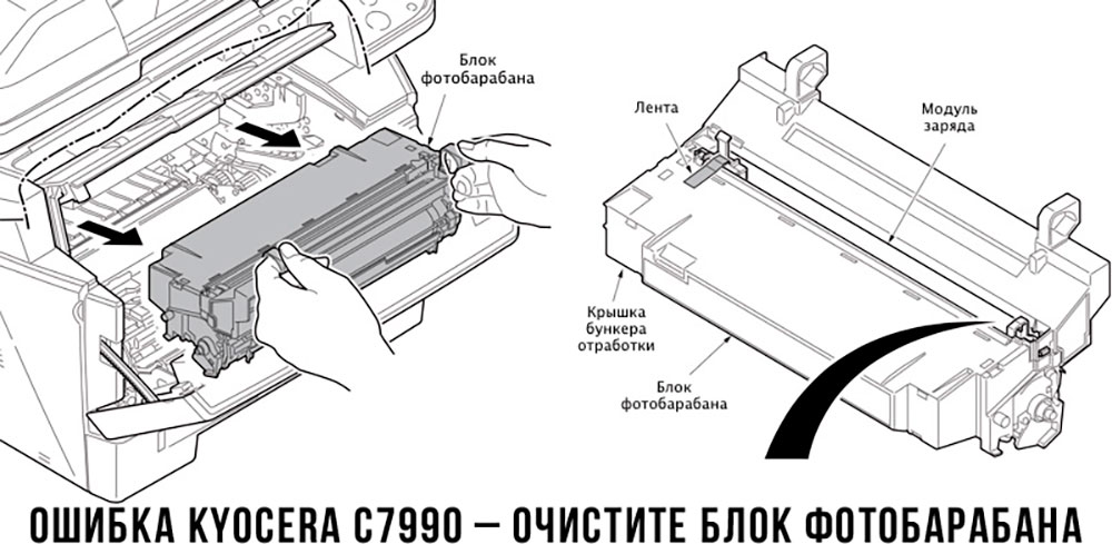
Чтобы потребитель мог наверняка определить проблему, рекомендуем использовать утилиту Kyocera Client Tool, которая идет в комплекте с драйверами принтера.
Ваше Имя:
Ваш вопрос:
Внимание: HTML не поддерживается! Используйте обычный текст.
Оценка:
Плохо
Хорошо
Введите код, указанный на картинке:

Если при работе с копировальном аппаратом у вас возникли проблемы, и система выдает код ошибки, вы можете идентифицировать ее с помощью данной таблицы.
Коды ошибок Kyocera-Mita указаны для более поздних моделей копиров. Если вы являетесь владельцем более ранней модели, необходимо к трехзначному коду ошибки прибавить знак «0».
Общие ошибки
| Код ошибки | Описание |
|---|---|
| 0030 | Fax control PWB system problem |
| 0070 | Fax control PWB incompatibility detection problem |
| 0100 | Backup memory read/write problem (main board) |
| 0110 | Backup memory data problem (main board) |
| 0120 | Drum EEPROM read/write problem (для 2550) |
| 0130 | Backup memory read/write problem (main PCB EEPROM) (для 1650/2050/2550) |
| 0140 | Backup memory data problem (main PCB EEPROM) (для 1650/2050/2550) |
| 0150 | Backup memory read/write problem (engine board) |
| 0160 | Backup memory data problem (engine board) |
| 0170 | Accounting count problem |
| 0180 | Machine number mismatch |
| 0210 | Communication problem between the main board and engine board (для KM-1500/1620/2020/1635/2035/1650/2050/2550/6030/8030, FS-1018/1118) |
| Communication problem between the main board and operation board (для KM-1525/1530/2030/2530/3530/6230/4530/5530/6330/7530) | |
| 0240 | Printer board PWB communication problem |
| 0250 | Scanner network board communication problem |
| 0280 | Communication problem between the fax control PWB and main PWB |
| 0320 | Side deck communication problem |
| 0340 | Finisher communication problem |
| 0410 | Optional DP communication problem |
| 0420 | Optional first paper feeder communication problem |
| Large paper deck /paper feed desk communication problem /Side deck communication problem | |
| 0440 | Finisher communication problem |
| 0450 | Mailbox communication problem |
| 0470 | Switchback unit communication problem |
| 0500 | Optional second paper feeder communication problem |
| 0510 | Optional third paper feeder communication problem |
| 0600 | DIMM problem (для 2530/3530) |
| 0610 | Bitmap (DIMM) problem |
| 0620 | Memory input interface problem |
| 0630 | DMA problem |
| 0640 | Hard disk drive problem |
| 0800 | Image processing problem (JAM05 is detected twice) |
| 0820 | Fax control PCB CG ROM checksum error |
| 0830 | Flash ROM program area checksum error |
| 0860 | Fax control PCB software switch checksum error |
| 0870 | Fax control PWB to main PWB high capacity data transfer problem |
| 0880 | Fax control PWB program archive problem |
| 0890 | Fax control PCB CG font archive problem |
| 0900 | Fax software incompatibility detection problem |
| 0920 | Fax file system error |
| 0960 | Developer EEPROM read/write problem (для 2550/6030/8030) |
| 1000 | Exposure lamp problem |
| 1010 | Lift motor 1 error |
| 1020 | Lift motor 2 error |
| 1030 | Lift motor 3 error |
| 1040 | Lift motor 4 error |
| 1100 | Paper deck motor 1 problem [Drawer 3] |
| 1110 | Paper deck motor 2 problem [Drawer 4] |
| 1120 | Deck right lift position problem |
| 1130 | Deck left lift position problem |
| 1140 | Side deck lift motor (going up) problem |
| 1150 | Side deck lift motor (going down) problem |
| 1160 | Large paper deck (paper feed desk) sequence problem |
| 1170 | Large paper deck (paper feed desk) incorrect type problem |
| 2000 | Main motor problem |
| Image forming motor problem (для 6230/4530/5530/6330/7530) | |
| 2500 | Paper feed motor problem |
| 2550 | Paper conveying motor problem (для 4530/5530) |
| 2600 | Deck conveying motor /desk drive motor problem |
| 2640 | Side deck drive motor problem |
| 3100 | Scanner carriage problem |
| 3200 | Exposure lamp problem |
| 3300 | Optical system (AGC) problem |
| 4000 | Polygon motor synchronization problem |
| 4010 | Polygon motor steady-state problem |
| 4100 | BD initialization (A) problem |
| 4110 | BD initialization (B) problem |
| 4200 | BD steady-state problem |
| 5100 | Main charger problem |
| 5110 | Transfer/separation high voltage problem |
| 5300 | Broken cleaning lamp wire |
| 5500 | Drum surface potential sensor problem 1 |
| 5510 | Drum surface potential sensor problem 2 |
| 5600 | Drum surface potential problem 1 |
| 5610 | Drum surface potential problem 2 |
| 6000 | Broken fixing heater wire |
| 6020 | Abnormally high fixing unit thermistor temperature |
| 6030 | Broken fixing unit thermistor |
| 6050 | Abnormally low fixing unit thermistor temperature |
| 6100 | Broken fixing heater wire |
| 6200 | Abnormally low fixing unit thermistor temperature |
| 6300 | Abnormally high fixing unit thermistor temperature |
| 6400 | Zero-crossing signal problem |
| 6410 | Fixing unit connector insertion problem |
| 6420 | Fixing fuse cut problem |
| 6420 | Broken fixing unit thermistor wire |
| 7100 | Toner sensor problem |
| 7300 | Broken external temperature thermistor wire (для KM-1505/1510/1810/4230/5230/6230) |
| Toner sensor problem/ Toner hopper problem (для KM-2530/3530/3035/4035/5035/6230/4530/5530/6330/7530/6030/8030) | |
| 7310 | Short-circuited external temperature thermistor |
| 7400 | Image formation unit connector insertion problem |
| Developing unit connector insertion problem (для 2550) | |
| 7410 | Drum unit connector insertion problem |
| 7750 | Drum type mismatch problem A (для 1635/2035) |
| 7760 | Drum type mismatch problem B (для 1635/2035) |
| 7800 | Broken external temperature thermistor |
| 7810 | Short-circuited external temperature thermistor |
KM-1500, FS-1018/1118 (KM-1820)
| Код ошибки | Описание |
|---|---|
| 0220 | Communication problem between the main board and operation board (для 1018/1118) |
| F— | Controller system error (для 1018/1118) |
| F010 | ROM checksum error (для 1118) |
| F012 | |
| 7980 | Waste toner reservoir overflow problem (when the total number of copies is less than 100 thousand sheets) |
| 7990 | Waste toner reservoir overflow problem (when the total number of copies is 100 thousand sheets or more) |
KM-1505/1510/1810/1525/1530/2030
| Код ошибки | Описание |
|---|---|
| 0210 | Printer board communication problem (для 1505/1510/1810) |
| 0400 | DIMM problem |
| 0410 | Bitmap problem |
| 0430 | DMA problem |
| 1040 | Optical system problem (AGC) |
Kyocera-Mita 3035/4035/5035
| Код ошибки | Описание |
|---|---|
| 0100 | Operation unit PCB backup memory read/write error |
| 0110 | Operation unit PCB backup memory data problem |
| 0210 | MMI communication problem |
| 0320 | Energy save communication problem |
| 7450 | Image formation unit fuse cut problem |
Kyocera Mita 4230/5230
| Код ошибки | Описание |
|---|---|
| 0010 | Memory copy PCB 1 communication problem |
| 0030 | Memory copy PCB 2 communication problem |
| 0100 | RAM/ROM problem |
| 0220 | Communication problem between the engine PCB and main PCB |
| 0230 | Scanner communication problem |
| 0260 | Memory copy PCB 1 communication problem |
| 0320 | Large paper deck communication problem /Paper feed desk communication problem |
| 0360 | Memory copy PCB 2 communication problem |
| 0370 | Communication microcomputer problem |
| 1040 | Optical system problem (AGC) |
| 2100 | Paper conveying motor problem |
| 2200 | Side registration motor problem |
| 2300 | Paper feed motor problem |
| 2310 | Desk drive motor problem |
| 2410 | Upper lift motor problem |
| 2420 | Lower lift motor problem |
| 2430 | Upper desk lift motor problem |
| 2440 | Lower desk lift motor problem |
| 3320 | Scanner watchdog problem |
| 3400 | Original detection position problem |
| 7400 | Toner hopper problem |
| 9200 | Deck paper conveying motor problem |
| 9210 | Paper deck motor 1 problem |
| 9220 | Paper deck motor 2 problem |
| 9230 | Right lift position problem |
| 9240 | Left lift position problem |
Kyocera-Mita 6030/8030
| Код ошибки | Описание |
|---|---|
| 0060 | Main PWB type mismatch error |
| 0130 | Backup memory (EEPROM) device problem |
| 0140 | Backup memory (EEPROM) data problem |
| 0220 | Scanner communication problem |
| 0330 | Relay board communication problem |
| 0460 | Duplex unit communication problem |
| 0470 | Sheet inserter communication problem (optional document finisher) |
| 0500 | Paper feed unit communication error (cassette 1 and 2) |
| 0510 | Paper feed unit communication error (cassette 3 and 4) |
| 0700 | Side feeder EEPROM error (optional side feeder) |
| 0750 | Document finisher EEPROM error |
| 0970 | Cleaning unit EEPROM error |
| 1200 | Duplex side registration motor error |
| 2100 | Developing motor error |
| 2200 | Drive motor error |
| 2300 | Fuser motor error |
| 2550 | Transfer motor error |
| 3210 | CIS lamp problem |
| 3310 | Optical system (AGC) problem (DP) |
| 3500 | Communication error between scanner and SHD |
| 3900 | Backup memory read/write error (scanner PWB) |
| 3910 | |
| 4120 | BD initialization (C) problem |
| 7200 | Broken drum thermistor wire |
| 7210 | Shorted drum thermistor |
| 9040 | DP lift motor going up error |
| 9050 | DP lift motor going down error |
| 9060 | DP EEPROM error |
| 9070 | Communication problem between DP and SHD |
| 9080 | Communication problem between DP and CIS |
Kyocera Mita 6230
| Код ошибки | Описание |
|---|---|
| 0010 | Memory PCB communication problem |
| 0100 | RAM/ROM problem |
| 0260 | Memory copy PCB 1 communication problem |
| 0350 | Mailbox communication problem |
| 0370 | Communication microcomputer problem |
| 0380 | Hard disk problem |
| 0390 | DIMM problem |
| 1040 | Optical system problem (AGC) |
| 2100 | Drive motor problem / Paper conveying motor problem |
| 2200 | Paper feed motor problem |
| 2300 | Large paper deck right lift motor problem |
| 2310 | Large paper deck left lift motor problem |
| 2420 | Upper lift motor problem |
| 2430 | Lower lift motor problem |
| 6500 | Broken fixing unit thermistor wire |
| 7200 | Broken drum thermistor wire |
| 7210 | Shorted drum thermistor |
| 7220 | Broken drum heater wire |
KyoceraMita 6330/7530
| Код ошибки | Описание |
|---|---|
| 1060 | Large paper deck left lift motor problem |
| 2550 | Drive motor problem |
| 7520 | Shorted drum thermistor |
| 7530 | Broken drum thermistor wire |
Ошибки финишеров
| Код ошибки | Описание |
|---|---|
| 8010 | Finisher paper conveying motor problem |
| 8030 | Finisher (upper) paper conveying belt problem |
| 8140 | Finisher tray elevation motor problem /Main tray problem |
| 8170 | Finisher front side registration motor problem |
| 8180 | Finisher rear side registration motor problem |
| Finisher rear jogger motor problem (для 4230/5230) | |
| 8190 | Finisher trailing edge registration motor problem |
| 8210 | Finisher stapler motor problem |
| 8220 | Finisher rear stapler problem |
| 8300 | Document finisher centerfold unit communication problem |
| 8310 | Document finisher centerfold unit side registration guide problem |
| 8320 | Document finisher centerfold unit centering plate problem |
| 8330 | Document finisher centerfold blade problem |
Ошибки финишеров KM-2530/3530/3035/4035/5035
| Код ошибки | Описание |
|---|---|
| 8300 | Booklet stitcher paper ejection motor problem |
| 8310 | Booklet stitcher elevation motor problem |
| 8320 | Booklet stitcher rear jog motor problem |
| 8330 | Booklet stitcher front jog motor problem |
| 8340 | Booklet stitcher staple motor problem |
| 8350 | Booklet stitcher batch processing motor problem |
| 8360 | Booklet stitcher stapler shift motor problem |
| 8370 | Booklet stitcher paddle motor problem |
| 8380 | Booklet stitcher folding problem |
| 8390 | Booklet stitcher backup RAM data problem |
| 8400 | Booklet stitcher incorrect type problem |
| 8410 | Booklet stitcher punch motor problem |
| 8420 | Booklet stitcher shift motor problem |
| 8430 | Booklet stitcher punch communication problem |
| 8440 | Booklet stitcher punch sensor problem |
| 8450 | Booklet stitcher side punch sensor problem |
| 8460 | Booklet stitcher punch backup RAM data problem |
| 8470 | Booklet stitcher punch dust sensor problem |
| 8480 | Booklet stitcher broken punch power source wire problem |
| 8500 | Mailbox drive motor problem |
Ошибки финишера KM-6230
| Код ошибки | Описание |
|---|---|
| 8180 | Finisher rear jogger motor problem |
| 8310 | Booklet stitcher paper ejection motor problem |
| 8320 | Booklet stitcher elevation motor problem |
| 8330 | Booklet stitcher jog motor problem |
| 8340 | Booklet stitcher staple motor problem |
| 8350 | Booklet stitcher stapler unit shift motor problem |
| 8360 | Booklet stitcher stack level detection sensor problem |
| 8370 | Booklet stitcher punch motor problem |
| 8380 | Booklet stitcher punch shift motor problem |
| 8390 | Booklet stitcher swing motor problem |
| 8400 | Booklet stitcher backup RAM data problem |
| 8410 | Booklet stitcher punch unit backup RAM data problem |
| 8420 | Booklet stitcher positioning plate motor problem |
| 8430 | Booklet stitcher folding motor problem |
| 8440 | Booklet stitcher guide motor problem |
| 8450 | Booklet stitcher jog motor problem |
| 8460 | Booklet stitcher rear staple motor problem |
| 8470 | Booklet stitcher front staple motor problem |
| 8480 | Booklet stitcher thrust motor problem |
| 8490 | Booklet stitcher communication error |
Ошибки финишеров KM-6330/7530/6030/8030
| Код ошибки | Описание |
|---|---|
| 8000 | Document finisher incorrect type problem (для 6330/7530) |
| 8020 | Finisher punch motor problem |
| 8040 | Finisher lower paper conveying belt problem |
| 8150 | Finisher multi job tray problem |
| 8170 | Front upper side-registration guide problem |
| 8180 | Finisher rear upper side-registration guide problem |
| 8190 | Finisher lower side-registration guide problem |
| 8220 | Finisher front clincher problem |
| 8230 | Finisher rear stapler problem |
| 8240 | Finisher rear clincher problem |
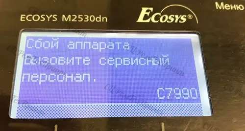
В статье речь пойдет о таких аппаратах Kyocera, как:
- ECOSYS M2030dn PN, M2030dn, M2035dn, M2040DN, M2040DW, M2135DN, M2530dn, M2535dn, M2540DN, M2540DW, M2635DN, M2635DW, M2640IDW, M2735DN, M2735DW, M2835DN, M2835DW, P2035d, P2035dn, P2040DN, P2040DW, P2135d, P2135dn, P2235D, P2235DN, P2235DW, P2335D, P2335DN, P2335DW;
- FS-1028MFP, FS-1028MFP/DP, FS-1030MFP, FS-1030MFP/DP, FS-1035MFP/DP, FS-1120D, FS-1120DN, FS-1128MFP, FS-1130MFP, FS-1135MFP, FS-1320D, FS-1320DN, FS-1350DN, FS-1370DN;
Ошибка 7990 на аппаратах K yocera возникает, как правило, при пробеге около 70 000 стр. (при использовании неоригинального тонер-картриджа или заправки картриджа).
Что означает «C7990»?
Первая и основная причина данной ошибки — переполнен бункер отработки драм-юнита (блок фотобарабана).
Остатки порошка с фотобарабана счищаются в данный бункер с помощью чистящего лезвия (ракеля). Постепенно резервуар заполняется отработанным тонером и при переполнении появляется ошибка 7990.
Очистить бункер можно самостоятельно. Но будьте осторожны! Тонер очень летуч и очень плохо отмывается. Никаких работающих вентиляторов рядом! Действуйте очень осторожно. В идеале проводить данную процедуру с помощью специального тонерного пылесоса. НЕЛЬЗЯ использовать бытовой пылесос для чистки бункера! Другой вариант: провести чистку бункера от отработанного тонера на улице.
Где находится бункер отработанного тонера?
Бункер расположен за блоком фотобарабана DK. Чтобы добраться до него необходимо вынуть блок проявки DV. Блок проявки — это блок, в который вставляется тонер-картридж.
Итак, устранить ошибку C7990 следующим образом:
1. Выключить принтер (МФУ) Kyocera и открыть переднюю крышку
2. Вынуть картридж и блок проявки

3. Извлечь драм-юнит потянув за ручки по бокам. Ручки бывают зеленого цвета (DK-150, DK-170), а на некоторых драм-юнитах голубого цвета (DK-1150)

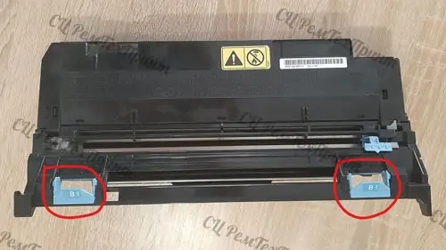
4. За задней частью фотобарабана на торце по бокам находятся 2 съемные заглушки или 2 несъемные вогнутые круги.

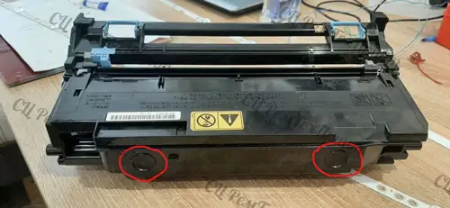
Вариант с заглушками: подцепить заглушки отверткой, ножницами или другим предметом и потянуть вверх. С этих отверстий АККУРАТНО высыпать отработанный тонер в пакет или в ведро. В идеале воспользоваться тонерным пылесосом (в домашних условиях не обязательно). Пользоваться бытовым пылесосом крайне не рекомендуем, это приведет к поломке Вашего домашнего пылесоса!
Без заглушек: в домашних условиях очистить фотобарабан от тонера можно просверлив дырочки в окружностях и высыпать тонер в ведро (пакет) через данные отверстия. А затем заклеить их скотчем.
Специалисты нашего сервисного центра проводят чистку бункера от отработанного тонера на выезде не нарушая целостности фотобарабана! Мы не сверлим отверстия! Чистим блок с помощью тонерного пылесоса. Стоимость услуги от 1600 руб.
5. Собрать аппарат в обратном порядке: фотобарабан → блок проявки → картридж.
6. Включить принтер (МФУ). Ошибка исчезла.
После процедуры аппарат начал печатать белые листы? Это значит, что фотобарабан вставлен не до конца. Необходимо еще раз разобрать и собрать аппарат.
7. Помним, что ресурс драм-юнита 100 000 стр. После чего аппарат выдаст сообщение «Замените MK».
Какие еще есть причины возникновения ошибки с7990?
Причиной может послужить выход из строя датчика или платы управления. В этом случае лучше вызвать специалиста сервисного центра.
P.S. При переполненном бункера некоторые аппараты не всегда выдают ошибку С7990 на дисплее. Иногда пользователь об этом может узнать, когда принтер начинает трещать. Если вовремя не провести чистку, ломается шестерёнка. В этом случае, необходим уже ремонт или замена фотобарабана (бункера WT)