
Answer #1: Posted by freginold on September 21st, 2015 8:22 AM
This answer was accepted by the poster of the original question.
freginold

Member since:
December 20th, 2011
Points:
23,240,715

1,100
points
Hello, sounds can be very hard to troubleshoot on a copier without being able to physically hear them. However, here are some tips that may help:
— If the sounds only occur when copying/printing, try cleaning the rollers in the area where the sound is coming from. If you’re not sure how to clean them, just use a damp cloth or lint-free rag. If you have compressed air, also clean the bearings and bushings on the feed shafts.
— If it sounds like a clicking noise, then it could be a bad bearing in the fusing unit.
— If it sounds like a very rapid clicking, it could be a chipped gear.
— If it is a high-pitched squeal or squeak, it could be dirty rollers or a dirty bushing.
Fax System (W) Operation Guide Rev-2.2013.1 — Page 209
… Setting
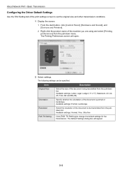
Click [FAX TX Setting] to set the original size and other transmission conditions.
1 Display the screen. 1 From the start button, click [Control Panel], [Hardware and Sound], and [Devices and Printers]. 2 Right-click the product name of the machine you are using and select [Printing preferences] from the pull-down list.
Item
Description
Original Size…
Kyocera Net Viewer Operation Guide Rev 5.3 2013.06 — Page 47

… list. Network Groups List
The device display name and IP address appearing in the title at the top of the Network Groups dialog box represent the selected device. The columns in ascending or… contains up to 20 groups, plus the Other group which is selected by the application. Device
Network Groups
You can be resized horizontally and vertically, minimized, maximized, or restored. For …
PRESCRIBE Commands Technical Reference Manual — Rev. 4.9 — Page 219

…the lower left UR: upper right
Device-Control Instructions
KC-GL uses device-control instructions to return buffer …appear in DeviceControl Instructions on the parallel interface. If device-control instructions are received via the RS-232C interface.
Output Extended Status (ESC.O)
This instruction returns printing system status information regarding:
• On-line status • Cover…
Printing System (11),(12),(13),(14) Color Printing Guide (Fiery E100) — Page 8
… E100 Titles in italics Windows
Refers to
E100 (in illustrations and examples) TASKalfa XX50ci Fiery E100 Color Server Other documents in this set Microsoft Windows XP,…Topics for which additional information is available by starting Help in bold, for example, output profile, that appear throughout this document. A caution concerning operations that may lead to death or injury to persons if not…
Printing System (11),(12),(13),(14) Configuration and Setup Guide (Fiery E100) — Page 8

Term or convention Aero Copier E100 Titles in italics Windows
Refers to
E100 (in illustrations and examples) TASKalfa XX50ci Fiery E100 Color Server Other documents in this set Microsoft Windows XP, Windows Vista, Windows 7, Windows Server 2003/2008/2008 R2 Topics for which …
Printing System (11),(12),(13),(14) Utilities Guide (Fiery E100) — Page 6

…
This document uses the following terminology and conventions. Term or convention Aero Copier E100 Titles in italics Windows
Refers to
E100 (in illustrations and examples) TASKalfa XX50ci Fiery E100 Color Server Other documents in this document refers you to Help for additional information and explains how to access Help for which…
Printing System (11),(12),(13),(14) Printing Guide (Fiery E100) — Page 8

…
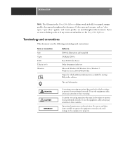
This document uses the following terminology and conventions.
Term or convention Aero Copier E100 Titles in italics Windows
Refers to
E100 (in illustrations and examples) TASKalfa XX50ci Fiery E100 Color Server Other documents in this set Microsoft Windows XP, Windows Vista, Windows 7, Windows Server 2003/2008/2008 R2 Topics for which…
Setup Tool Operation Guide Rev-1 — Page 42
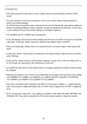
…-1024MFP and FS-1124MFP are not supported.
• In the edit dialogs of Device Accounting Settings and Account List, default values are automatically set when a file is not set …the copy counter setting of the address book cover page is grayed out and the contents cannot be changed.
• Data can be…-3050, KM-4050, KM-5050, and TASKalfa 300i.
TASKalfa 3051ci/3551ci/4551ci/5551ci Operation Guide Rev-1 2013.6 — Page 50
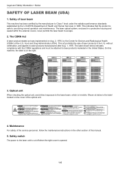
…in the other section of this machine, the label is safe to the laser unit is cut off when the right cover is invisible. The label shown …Devices and Radiological Health (CDRH) of laser products in 1968. Safety of laser beam
This machine has been certified by the manufacturer to the laser beam, which is opened.
1-6 This indicates that the product is on the right.
3051ci
3551ci…
TASKalfa 3051ci/3551ci/4551ci/5551ci Operation Guide Rev-1 2013.6 — Page 52
…’s exclusive remedy shall be replacement of any other rights, which are not genuine KYOCERA brand parts or …(d) have no obligation to furnish labor. This warranty covers Maintenance Kits and the components of Maintenance Kits included …Information > Notice
Warranty (the United States and Canada)
3051ci / 3551ci / 4551ci / 5551ci MULTIFUNCTIONAL PRODUCT LIMITED WARRANTY
KYOCERA Document Solutions…
TASKalfa 3051ci/3551ci/4551ci/5551ci Operation Guide Rev-1 2013.6 — Page 60
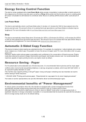
…resources. Sleep
The device automatically enters Sleep when 30 minutes (for 3051ci), 45 minutes (for 3551ci), or 60 minutes (for 4551ci or 5551ci) have passed since the device was last used … be used . It is recommended that automatically activates energy-saving mode when the machine is equipped with the device within a set to further saving of no activity that recycled as well as …
TASKalfa 3051ci/3551ci/4551ci/5551ci Operation Guide Rev-1 2013.6 — Page 68

… (Option)
Network Network
TWAIN Scanning WIA Scanning
TWAIN and WIA are using the machine with a network cable (1000BASE-T, 100BASE-TX or 10BASE-T)
Administrator’s PC
Command … for communication between software applications and image acquisition devices. Optional Network (page 8-47)
2-6 Installing and Setting up the Machine > Determining the Connection Method and Preparing Cables
…
TASKalfa 3051ci/3551ci/4551ci/5551ci Operation Guide Rev-1 2013.6 — Page 170

…
1 Click [Start] button on the Windows, and then click [Devices and Printers]. 2 Right-click the printer driver icon of the machine, and click the [Printer properties] menu of
the printer driver. … the taskbar at the bottom right of the screen and then click the item you want to [Black] and click [OK]. The following :
NOTE When canceling printing from this machine, refer to Canceling Jobs on…
TASKalfa 3051ci/3551ci/4551ci/5551ci Operation Guide Rev-1 2013.6 — Page 344
Model Name 3051ci 3551ci 4551ci 5551ci
Login User Name 3000 3500 4500 5500
Login …
User Name
Result Completed
Completed
Completed
1/1
Error
Completed
Detail
Printing Jobs
Sending Jobs
Storing Jobs
Device/ Communicate
Paper/ Supplies
Close
NOTE
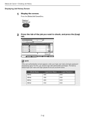
If the user authentication screen appears, enter your login user name and login password and press [Login]. Press the [Status/Job…
TASKalfa 3051ci/3551ci/4551ci/5551ci Operation Guide Rev-1 2013.6 — Page 349
… such as waiting or printing are displayed. • Press [Format] to this machine or check their status.
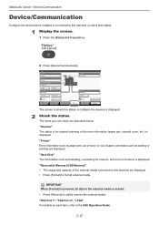
1 Display the screen.
1 Press the [Status/Job Cancel] key.
2 Press [Device/Communicate].
Line Off
Device/ Communicate
i-FAX
Paper/ Supplies
Check New FAX Close
The screen to this machine are displayed.
«Removable Memory (USB Memory)» • The usage and capacity…
TASKalfa 3051ci/3551ci/4551ci/5551ci Operation Guide Rev-1 2013.6 — Page 391
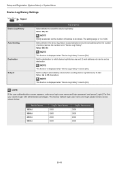
… to [On]. NOTE
If the user authentication screen appears, enter your login user name and login password and press [Login]. Set the subject automatically entered when sending device log histories by E-mail. The factory default login user name and login password are sent.
Model Name 3051ci 3551ci 4551ci 5551ci
Login User Name 3000 3500…
TASKalfa 3051ci/3551ci/4551ci/5551ci Operation Guide Rev-1 2013.6 — Page 407
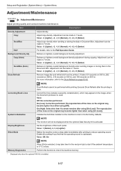
…machine enter a sleep state immediately after printing to check the machine memory.
* Displayed only when the optional FAX Kit is selected, it to return it may appear on the machine…machine maintenance. Adjust copy density. Adjustment can be made in 7 levels.
Adjustment can be made in 7 levels. It takes 331 seconds on 3051ci, 282 seconds on 3551ci… the operating sound is done….
TASKalfa 3051ci/3551ci/4551ci/5551ci Operation Guide Rev-1 2013.6 — Page 571

… 8-39 Reserve Next 5-23 Reserved copy 5-23 Resolution 6-69, 11-25, 11-26 Responding to Messages 10-24 Restart Entire Device 8-52 Restart Network 8-46 Right Cover 1 Lever 2-3 Right Cover 2 2-3 Right Cover 2 Lever 2-3 Right Cover 3 Lever 2-3 Right Job Separator 11-6
S
Safety Conventions 1-2 Safety Conventions in This Guide 1-2 Saturation 6-31 Scan Resolution
Default 8-17 Security Level 8-49 Send…
TASKalfa 3051ci/3551ci/4551ci/5551ci Printer Driver User Guide — Page 2
…TASKalfa 3551ci TASKalfa 4551ci TASKalfa 5551ci
© 2013 KYOCERA Document Solutions Inc. and/or other countries. Adobe®, Acrobat®, Adobe Reader®, Photoshop® and PostScript® are registered trademark of Apple Inc. KPDL is a trademark of Hewlett-Packard Company. User Interface screen…guide is a trademark in the United States and other countries, licensed …
TASKalfa 3051ci/3551ci/4551ci/5551ci Printer Driver User Guide — Page 46
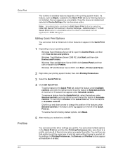
… the feature under Available controls, and click the right arrow to move the feature to Selected controls. Windows 7 and Windows Server 2008 R2: click Start, and then click Devices and Printers.
To use that profile to print the same type of driver features to appear in the Quick Print tab.
1 Depending on the…
 Если с аппаратом Kyocera TASKalfa 1800, Kyocera TASKalfa 2200 произошла проблема, откроется следующий экран с уведомлением.
• Индикатор [Внимание] на панели управления горит или мигает.
• На дисплее сообщений панели управления аппарата появилось сообщение об ошибке.
Если индикатор [Внимание] горит или мигает и на дисплее сообщений панели управления аппарата появилось сообщение об ошибке, проверьте KYOCERA Client Tool или Монитор состояния.
ПРИМЕЧАНИЕ Если индикаторы постоянно горят и мигают не так, как описано выше, вероятно, произошла ошибка службы. Выключите питание, отсоедините шнур питания и вставьте его обратно, после чего включите питание. Это может помочь сбросить ошибку. Если ошибка не исчезает, свяжитесь со своим представителем сервисной службы (тел. в Минске +375 17 291-28-24)
Ниже описаны неполадки, которые не могут быть устранены пользователем
|
Дисплей сообщений |
Описание |
Меры устранения |
|
Бункер отраб тонера перепол. или не уст. |
Бункер для отработанного тонера установлен неправильно |
Установите Бункер для отработанного тонера должным образом |
|
Бункер для отработанного тонера заполнен |
Замените бункер отработанного тонера |
|
|
Встряхните картр. с тонером |
Тонер слежался |
Откройте переднюю крышку аппарата и вытяните контейнер с тонером. Сильно встряхните контейнер с тонером и установите его на место |
|
Вызовите сервисный персонал. |
В аппарате произошла ошибка |
Обратите внимание на код ошибки, отображаемый в дисплее сообщений, и свяжитесь с представителем сервисной службы (тел. в Минске +375 17 291-28-24) |
|
Выньте бумагу с внутреннего лотка |
Извлеките бумагу из внутреннего лотка. Нажмите клавишу [OK], чтобы возобновить печать |
|
|
Добавьте тонер |
Закончился тонер |
Замените контейнер с тонером TK-4105 |
|
Загрузите бумагу в кассету # |
↑↓ (отображается попеременно) |
Загрузите бумагу. Нажмите клавишу [OK] и перейдите к следующему шагу. • Для выбора другого устройства подачи выберите [Выберите бумагу]. • Для печати на бумаге, в настоящее время находящейся в устройстве подачи, выберите [Продолж. без изм.] |
|
Загрузите бумагу в универсальный лоток |
↑↓ (отображается попеременно) |
Загрузите бумагу. Нажмите клавишу [OK] и перейдите к следующему шагу. • Для выбора другого устройства подачи выберите [Выберите бумагу]. • Для печати на бумаге, в настоящее время находящейся в устройстве подачи, выберите [Продолж. без изм.] |
|
Закройте автоподатчик оригиналов |
Открыт автоподатчик оригиналов |
Откройте и закройте автоподатчик оригиналов |
|
Закройте крышку автопод. оригиналов |
Открыта верхняя крышка автоподатчика оригиналов |
Откройте и закройте крышку автоподатчика оригинало |
|
Закройте переднюю крышку |
Открыта передняя крышка |
Откройте и закройте переднюю крышку |
|
Закройте правую крышку # |
Открыта какая-либо крышка |
Откройте и закройте крышку, обозначенную на экране |
|
Замятие бумаги. (DP) |
В автоподатчике произошло замятие бумаги. |
См. Устранение замятия бумаги в Руководстве по эксплуатации и извлеките замятую бумагу |
|
Замените МК |
Необходимо производить замену деталей комплекта техобслуживания MK-4105 (ремкомплекта) каждые 150 000 страниц печати. |
Данная операция должна производиться специалистом. Обратитесь к представителю сервисной службы (тел. в Минске +375 17 291-28-24) |
|
Замятие |
Произошло замятие бумаги в кассете или универсальном лотке |
См. Устранение замятия бумаги и извлеките замятую бумагу |
|
Извлеките оригиналы из автоподатчика |
Для продолжения работы необходимо извлечь оригиналы из автоподатчика оригиналов |
Извлеките оригиналы из автоподатчика оригиналов |
|
Кабель USB был отключен |
Кабель USB не подключен |
Нажмите клавишу [OK] и подключите кабель USB |
|
ПК выключен |
Нажмите клавишу [OK] и включите ПК |
|
|
Не удается найти KYOCERA Client Tool |
Нажмите клавишу [OK] и откройте KYOCERA Client Tool на ПК |
|
|
Макс. к-во сканируемых страниц |
Превышен предел сканирования |
Дальнейшее сканирование невозможно. Задание отменено. Нажмите клавишу [OK] |
|
Мало тонера. (Зам., когда законч.) |
Скоро понадобится заменить контейнер с тонером |
Получите новый контейнер с тонером TK-4105. |
|
Не оригинальный тонер |
Установлен контейнер с тонером не марки Kyocera |
Производитель не несет ответственности за повреждения, вызванные использованием неоригинального тонера. Мы рекомендуем использовать исключительно оригинальные контейнеры с тонером TK-4105. . |
|
Неверный ид. уч. зап. Задание отменено |
Указан неверный идентификатор учетной записи при внешней обработке задания. Задание отменено |
Нажмите клавишу [OK] |
|
Невозможна двусторонняя печать на этой бумаге |
Не возможна печать на бумаге выбранного формата или типа |
Нажмите клавишу [OK] и перейдите к следующему шагу: |
|
Недостаточно памяти. Невозможно начать выполнение задания |
Невозможно начать выполнение задания |
Повторите попытку позже |
|
Ограничено алгоритмом учета заданий(Печать) |
Задание отменено, поскольку его выполнение ограничено функцией учета заданий |
Нажмите клавишу [OK] |
|
Ограничено алгоритмом учета заданий(Сканер) |
Задание отменено, поскольку его выполнение ограничено функцией учета заданий |
Нажмите клавишу [OK] |
|
Очистите сканер |
Произошло загрязнение сканера |
Очистите щелевое стекло с помощью чистящей салфетки, поставляемой вместе с автоподатчиком оригиналов. |
|
Ошибка. Выключить |
— |
Отключите и снова включите аппарат с помощью выключателя питания |
|
Память переполнена |
Невозможно продолжить выполнение задания из-за отсутствия свободной памяти |
Измените разрешение печати с Быстр1200 до 600 dpi. См. Printer Driver User Guide |
|
Память сканера переполнена |
Дальнейшее сканирование невозможно из-за нехватки памяти сканера. |
Для отмены задания нажмите [OK] |
|
Перезагрузка печати. Задание отменено |
Предупреждение. Недостаточно памяти принтера. Задание отменено |
Нажмите клавишу [OK] |
|
Превышено ограничение учета заданий |
Превышено число распечаток из-за ограничения алгоритмом учета заданий. Достигнут предел печати |
Это задание отменено. Нажмите клавишу [OK] |
|
Уст.другую кассету |
Выбрано «Сдвиг» |
Для использования сдвига необходимо загрузить в другой лоток бумагу такого же формата, что и в выбранном устройстве подачи, но в другой ориентации |
|
Установите все оригиналы обратно и нажмите клавишу [Старт]. |
Возникает при печати двусторонних документов в режиме ручной двусторонней печати |
Извлеките оригиналы из автоподатчика оригиналов, расположите их в первоначальном порядке и положите обратно. Нажмите клавишу [OK], чтобы возобновить печать. Для отмены задания нажмите [Стоп] |
|
Установлен неизвестный тонер. ПК |
Региональная спецификация контейнера с тонером не соответствует спецификации аппарата |
Установите оригинальный контейнер с тонером Замените контейнер с тонером TK-4105 |
Все современные копировальные аппараты, мфу и принтеры Kyocera имеют возможность диагностировать все узлы устройства в режиме запуска и во время работы аппарата. По этому, если во время включения или во время работы произошел сбой, то техника Kyocera сможет сообщить о наличии ошибки.
В большинстве случаев у аппаратов Kyocera код ошибки отображается на дисплее, в остальных случаях тип ошибки зависит от последовательности и количества миганий индикаторов.
Если Ваш копировальный аппарат, МФУ или принтер Kyocera выдал на дисплее некий код, то узнать причину, описание возникновения ошибки, а так же в каком узле аппарата стоит искать проблему, Вы можете в этом разделе выбрав интересующую модель из списка.
Но диагностика не решит проблему сбоя аппарата, для этого лучше обратиться к профессиональным и опытным сервисным специалистам компании Kyomart! Позвоните нам по телефону
8 (343) 288-23-45 или отправьте запрос на электронную почту: sales@kyomart.ru , и мы обязательно свяжемся с Вами в кратчайшие сроки.
Код ошибки Описание ошибки Причина ошибки 0030 FAX control PWB system error
Processing with the fax software was disabled due to a hardware problem. Defective FAX control PWB. 0070 FAX control PWB incompatible detection Error
Abnormal detection of FAX control PWB incompatibility In the initial communication with the FAX control PWB, any normal communication command is not transmitted. FAX control PWB (The FAX PWB installed will not be the one designed for the machine. 0100 Backup memory device error EEPROM (Control PWB) 0120 MAC address data error
For data in which the MAC address is invalid. EEPROM (Control PWB) 0130 Backup memory read/write error (main NAMD) Flash memory (Control PWB) 0140 Backup memory data error (main NAND) Flash memory (Control PWB) 0150 Engine PWB EEPROM error
Detecting engine PWB EEPROM communication error. Improper installation engine PWB EEPROM. Defective engine PWB. Device damage of EEPROM. 0170 Billing counting error
A checksum error is detected in the main and engine backup memories for the billing counters. Data damage of EEPROM. Defective PWB. 0180 Machine number mismatch
Machine number of control does not match. Data damage of EEPROM. 0600 Expanded memory (DIMM) installing error
The expansion memory modules (DIMM) are not correctly mounted. Improper installation expanded memory (DIMM). 0610 Expanded memory (DIMM) error
The expansion memory modules (DIMM) mounted on the main PWB does not operate correctly. Defective expanded memory (DIMM). Defective main PWB. 0640 Hard disk error
The hard disk cannot be accessed. Defective hard disk. Defective main PWB. 0830 FAX control PWB flash program area checksum error
A checksum error occurred with the program of the FAX control PWB. Defective FAX software. Defective FAX control PWB. 0840 Faults of RTC
The time is judged to go back based on the comparison of the RTC time and the current time or five years or more have passed. The battery is disconnected from the main PWB. Defective main PWB. 0870 FAX control PWB to main PWB high capacity data transfer error
High-capacity data transfer between the FAX control PWB and the main PWB of the machine was not normally performed even if the data transfer was retried the specified times. Improper installation FAX control PWB. Defective FAX control PWB or main PWB. 0920 Fax file system error
The backup data is not retained for file system abnormality of flash memory of the FAX control PWB. Defective FAX control PWB. 0930 EEPROM bus error Defective drum PWB (EEPROM). Defective engine PWB (EEPROM). Defective engine PWB. Defective main PWB. 1010 Lift motor error
When the lift motor is driven, the motor over-current detection signal is detected continuously for 50 times (5 s) at 100 ms intervals. After the lift motor is driven, the ON status of lift sensor cannot be detected for 8 s. The cassette installed confirmation message is displayed on the operation panel, and even if the cassette is opened and closed, the cassette installed confirmation message is displayed 5 times successively. Defective bottom plate elevation mechanism in the cassette. Defective connector cable or poor contact in the connector. Defective drive transmission system of the lift motor. Defective lift motor. Defective engine PWB. 1020 PF lift motor error (paper feeder 1)
When the lift motor is driven, the motor over-current detection signal is detected continuously for 50 times (5 s) at 100 ms intervals. After the lift motor is driven, the ON status of lift sensor cannot be detected for 8 s. The cassette installed confirmation message is displayed on the operation panel, and even if the cassette is opened and closed, the cassette installed confirmation message is displayed 5 times successively. Defective bottom plate elevation mechanism in the cassette. Defective connector cable or poor contact in the connector. Defective drive transmission system of the PF lift motor. Defective PF lift motor. Defective PF main PWB. 1030 PF lift motor error (paper feeder 2)
When the lift motor is driven, the motor over-current detection signal is detected continuously for 50 times (5 s) at 100 ms intervals. After the lift motor is driven, the ON status of lift sensor cannot be detected for 8 s. The cassette installed confirmation message is displayed on the operation panel, and even if the cassette is opened and closed, the cassette installed confirmation message is displayed 5 times successively. Defective bottom plate elevation mechanism in the cassette. Defective connector cable or poor contact in the connector. Defective drive transmission system of the PF lift motor. Defective PF lift motor. Defective PF main PWB. 1500 PF heater 1 high temperature error (paper feeder 1)
A temperature higher than 75C/167F is detected. Defective connector cable or poor contact in the connector. Shorted PF thermistor 1. Defective PF fan motor 1. Defective PF main PWB. 1510 PF heater 2 high temperature error (paper feeder 1)
A temperature higher than 75C/167F is detected. Defective connector cable or poor contact in the connector. Shorted PF thermistor 2. Defective PF fan motor 2. Defective PF main PWB. 1520 PF heater 1 high temperature error (paper feeder 2)
A temperature higher than 75aC/167F is detected. Defective connector cable or poor contact in the connector. Shorted PF thermistor 1. Defective PF fan motor 1. Defective PF main PWB. 1530 PF heater 2 high temperature error (paper feeder 2)
A temperature higher than 75C/167F is detected. Defective connector cable or poor contact in the connector. Shorted PF thermistor 2. Defective PF fan motor 2. Defective PF main PWB. 1600 PF heater 1 low temperature error (paper feeder 1)
An external temperature higher than + 5C/+ 9F is not detected when one minute elapses after PF heater 1 is turned on. Defective connector cable or poor contact in the connector. PF thermistor 1 installed incorrectly. Defective PF thermistor 1. Broken PF heater 1. Defective PF heater PWB or PF main PWB. 1610 PF heater 2 low temperature error (paper feeder 1)
An external temperature higher than + 5C/+ 9F is not detected when one minute elapses after PF heater 2 is turned on. Defective connector cable or poor contact in the connector. PF thermistor 2 installed incorrectly. Defective PF thermistor 2. Broken PF heater 2. Defective PF heater PWB or PF main PWB. 1620 PF heater 1 low temperature error (paper feeder 2)
An external temperature higher than + 5C/+ 9F is not detected when one minute elapses after PF heater 1 is turned on. Defective connector cable or poor contact in the connector. PF thermistor 1 installed incorrectly. Defective PF thermistor 1. Broken PF heater 1. Defective PF heater PWB or PF main PWB. 1630 PF heater 2 low temperature error (paper feeder 2)
An external temperature higher than + 5C/+ 9F is not detected when one minute elapses after PF heater 2 is turned on. Defective connector cable or poor contact in the connector. PF thermistor 2 installed incorrectly. Defective PF thermistor 2. Broken PF heater 2. Defective PF heater PWB or PF main PWB. 1800 Paper feeder communication error
Communication error between engine PWB and optional paper feeder. Improper installation paper feeder. Defective connector cable or poor contact in the connector. Defective engine PWB. Defective PF main PWB. 2100 Developing motor error
The developing motor ready input is not given for 5 s during the main motor is ON. Defective connector cable or poor contact in the connector. Defective drive transmission system of the developing motor. Defective developing motor. Defective engine PWB. 2200 Drum motor error
The drum motor ready input is not given for 5 s during the drum motor is ON. Defective connector cable or poor contact in the connector. Defective drive transmission system of the drum motor. Defective drum motor. Defective engine PWB. 2330 Fuser pressure release motor error
When the fuser pressure release motor is driven, the motor over-current detection signal is detected continuously for 8 times (800 ms) at 100 ms intervals. Defective connector cable or poor contact in the connector. Defective drive transmission system of the fuser pressure release motor. Defective fuser pressure release motor. Defective engine PWB. 2340 Fuser pressure release motor time-out error
When the fuser pressure release motor is driven, the envelope switch (EVSW) is not detectable for 6 s. Defective connector cable or poor contact in the connector. Defective drive transmission system of the fuser pressure release motor. Defective fuser pressure release motor. Defective engine PWB. 2500 Paper feed motor error
The drum motor ready input is not given for 5 s during the paper feed motor is ON. Defective connector cable or poor contact in the connector. Defective drive transmission system of the paper feed motor. Defective paper feed motor. Defective engine PWB. 2600 PF paper feed motor error (paper feeder 1)
The drum motor ready input is not given for 2 s during the PF paper feed motor is ON. Defective connector cable or poor contact in the connector. Defective drive transmission system of the PF paper feed motor. Defective PF paper feed motor. Defective PF main PWB 2610 PF paper feed motor error (paper feeder 2)
The drum motor ready input is not given for 2 s during the PF paper feed motor is ON. Defective connector cable or poor contact in the connector. Defective drive transmission system of the PF paper feed motor. Defective PF paper feed motor. Defective PF main PWB. 2730 Developing release motor error
When the developing release motor is driven, the motor over-current detection signal is detected continuously for 8 times (800 ms) at 100 ms intervals. Defective connector cable or poor contact in the connector. Defective drive transmission system of the developing release motor. Defective developing release motor. Defective engine PWB. 2740 Developing release motor time-out error
When the developing release motor is driven, the developing release switch (DEVRSW) is not detectable for 1 s. Defective connector cable or poor contact in the connector. Defective drive transmission system of the developing release motor. Defective developing release motor. Defective engine PWB. 2820 Fuser motor error
The fuser motor ready input is not given for 5 s during the fuser motor is ON. Defective connector cable or poor contact in the connector. Defective drive transmission system of the fuser motor. Defective fuser motor. Defective engine PWB. 3100 ISU home position error
The home position is not correct when the power is turned on or at the start of copying using the table. Defective connector cable or poor contact in the connector. Defective home position sensor. Defective ISU motor. Defective CCD PWB. Defective main PWB. 3200 Exposure lamp error
When input value at the time of exposure lamp illumination does not exceed the threshold value between 5 s. Defective connector cable or poor contact in the connector. Defective exposure lamp. Defective inverter PWB or CCD PWB. Defective main PWB. 3300 AGC error
After AGC, correct input is not obtained at CCD. Defective connector cable or poor contact in the connector. Defective exposure lamp. Defective inverter PWB or CCD PWB. Defective main PWB. 3500 Communication error between scanner and ASIC
An error code is detected. Defective connector cable or poor contact in the connector. Defective CCD PWB. Defective main PWB. 4001 Polygon motor KM error
The polygon motor KM ready input is not given for 10 s during the polygon motor is ON. Defective connector cable or poor contact in the connector. Defective polygon motor KM. Defective engine PWB. 4002 Polygon motor CY error
The polygon motor CY ready input is not given for 10 s during the polygon motor is ON. Defective connector cable or poor contact in the connector. Defective polygon motor CY. Defective engine PWB. 4201 Laser output error (black)
The pin photo signal is not output from PD PWB K for one second while laser is emitted. Defective connector cable or poor contact in the connector. Defective APC PWB K. Defective PD PWB K. Defective engine PWB. 4202 Laser output error (cyan)
The pin photo signal is not output from PD PWB C for one second while laser is emitted. Defective connector cable or poor contact in the connector. Defective APC PWB C. Defective PD PWB C. Defective engine PWB. 4203 Laser output error (magenta)
The pin photo signal is not output from PD PWB M for one second while laser is emitted. Defective connector cable or poor contact in the connector. Defective APC PWB C. Defective PD PWB C. Defective engine PWB. 4204 Laser output error (yellow)
The pin photo signal is not output from PD PWB Y for one second while laser is emitted. Defective connector cable or poor contact in the connector. Defective APC PWB C. Defective PD PWB C. Defective engine PWB. 4600 LSU cleaning motor error
When the LSU cleaning motor is driven, the motor over-current detection signal is detected continuously for 50 times (5 s) at 100 ms intervals. Defective connector cable or poor contact in the connector. Defective drive transmission system of the LSU cleaning motor. Defective LSU cleaning motor. Defective engine PWB. 4700 VIDEO ASIC device error Defective connector cable or poor contact in the connector. Defective main PWB or engine PWB. 5301 Broken cleaning lamp K wire
When the cleaning lamp K is driven, the lamp over-current detection signal is detected continuously for 10 times (1 s) at 100 ms intervals. Defective connector cable or poor contact in the connector. Defective cleaning lamp K. Defective engine PWB. 5302 Broken cleaning lamp C wire
When the cleaning lamp C is driven, the lamp over-current detection signal is detected continuously for 10 times (1 s) at 100 ms intervals. Defective connector cable or poor contact in the connector. Defective cleaning lamp K. Defective engine PWB. 5303 Broken cleaning lamp M wire
When the cleaning lamp M is driven, the lamp over-current detection signal is detected continuously for 10 times (1 s) at 100 ms intervals. Defective connector cable or poor contact in the connector. Defective cleaning lamp K. Defective engine PWB. 5304 Broken cleaning lamp Y wire
When the cleaning lamp Y is driven, the lamp over-current detection signal is detected continuously for 10 times (1 s) at 100 ms intervals. Defective connector cable or poor contact in the connector. Defective cleaning lamp K. Defective engine PWB. 6000 Broken fuser heater wire
The detected temperature of fuser thermistor does not rise 1„aC/1.8„aF after the fuser heater has been turned on continuously for 10 s in warming up. The fuser temperature does not reach 100„aC/212„aF after the fuser heater has been turned on continuously for 30 s in warming up. The detected temperature of fuser thermistor does not reach the specified temperature (ready indication temperature) after the fuser heater has been turned on continuously for 60 s in warming up. The detected temperature of fuser thermistor does not rise 1„aC/1.8„aF after the fuser heater has been turned on continuously for 10 s during printing. Defective connector cable or poor contact in the connector. Fuser thermostat triggered. Broken fuser heater wire. Defective engine PWB. 6020 Abnormally high fuser thermistor temperature
The fuser thermistor detects a temperature higher than 240C/464F. By the activation of the high temperature error detection circuit (230C/446F or more) of fuser thermistor, the illumination of fuser heater was forcibly turned off and 10 s has elapsed. Shorted fuser thermistor. Defective engine PWB. 6030 Broken fuser thermistor wire
Input from fuser thermistor is 3 or less (A/D value) continuously for 1 s. Defective connector cable or poor contact in the connector. Broken fuser thermistor wire. Fuser thermostat triggered. Broken fuser heater wire. Defective engine PWB. 6400 Zero-cross signal error
The zero-cross signal does not reach the engine PWB for more than 1 s. Defective connector cable or poor contact in the connector. Defective power source PWB or engine PWB 7001 Toner motor K error
When the toner motor K is driven, the motor over-current detection signal is detected continuously for 50 times (5 s) at 100 ms intervals. Defective connector cable or poor contact in the connector. Defective drive transmission system of the toner motor K. Defective toner motor K. Defective engine PWB. 7002 Toner motor C error
When the toner motor C is driven, the motor over-current detection signal is detected continuously for 50 times (5 s) at 100 ms intervals. Defective connector cable or poor contact in the connector. Defective drive transmission system of the toner motor K. Defective toner motor K. Defective engine PWB. 7003 Toner motor M error
When the toner motor M is driven, the motor over-current detection signal is detected continuously for 50 times (5 s) at 100 ms intervals. Defective connector cable or poor contact in the connector. Defective drive transmission system of the toner motor K. Defective toner motor K. Defective engine PWB. 7004 Toner motor Y error
When the toner motor Y is driven, the motor over-current detection signal is detected continuously for 50 times (5 s) at 100 ms intervals. Defective connector cable or poor contact in the connector. Defective drive transmission system of the toner motor K. Defective toner motor K. Defective engine PWB. 7401 Developing unit K noninstalling error
No density detection signal is output from toner sensor K in developing unit K. Defective connector cable or poor contact in the connector. Defective toner sensor K. Defective engine PWB. 7402 Developing unit C noninstalling error
No density detection signal is output from toner sensor C in developing unit C. Defective connector cable or poor contact in the connector. Defective toner sensor K. Defective engine PWB. 7403 Developing unit M noninstalling error
No density detection signal is output from toner sensor M in developing unit M. Defective connector cable or poor contact in the connector. Defective toner sensor K. Defective engine PWB. 7404 Developing unit Y noninstalling error
No density detection signal is output from toner sensor Y in developing unit Y. Defective connector cable or poor contact in the connector. Defective toner sensor K. Defective engine PWB. 7411 Drum unit K non- installing error
The EEPROM of drum PWB K does not communicate normally. Installation of incompatible drum unit K. Defective connector cable or poor contact in the connector. Defective drum PWB K. Defective engine PWB. 7412 Drum unit C non- installing error
The EEPROM of drum PWB C does not communicate normally. Installation of incompatible drum unit K. Defective connector cable or poor contact in the connector. Defective drum PWB K. Defective engine PWB. 7413 Drum unit M non- installing error
The EEPROM of drum PWB M does not communicate normally. Installation of incompatible drum unit K. Defective connector cable or poor contact in the connector. Defective drum PWB K. Defective engine PWB. 7414 Drum unit Y non- installing error
The EEPROM of drum PWB Y does not communicate normally. Installation of incompatible drum unit K. Defective connector cable or poor contact in the connector. Defective drum PWB K. Defective engine PWB. 9500
…
9520 Contact the Service Administrative Division. 9530 Backup data error
The serial number of the machine written on the EEPROM of the engine PWB differs with that is written on both the flash memory of the engine PWB and the EEPROM of the drum PWB as a backup. Replacing both the engine PWB and the drum unit at the same time. F000 Main PWB — operation panel PWB communication error Defective main PWB. Defective operation panel PWB. F010 Main PWB checksum error Defective main PWB F020 Main PWB RAM checksum errors Defective main memory (RAM) on the main PWB. Defective expanded memory (DIMM). F040 Main PWB — print engine communication error Defective main PWB. Defective engine PWB. F041 Main PWB — scanner engine communication error Defective main PWB. Defective engine PWB. F050 Print engine ROM checksum error Defective engine PWB. F051 Scanner engine ROM checksum error Defective engine PWB. F278 Power supply in drive system error Main power switch was turned off without using the power key, or a power failure has occurred.
Kyocera TASKalfa 3051ci ошибка C2730 — ошибка связанная с позиционированием узла коротрона переноса. Может быть вызвана неисправностью датчика положения, двигателя подвода — отвода коротрона, шестерен привода, плохой контакт в разъемах.
Наш сервисный центр профессионально разбирается в вопросах ремонта и обслуживания многофункциональных устройств Kyocera.
Мы выполняем ремонт Kyocera TASKalfa 3051ci для устранения ошибки C2730.
Запрос стоимости
Стоимость
Ремонт принтеров
| Вид устройства и формат печати | Монохромные формата А4 | Монохромные формата А3 | Цветной формата А4 | Цветной формата А3 |
| Диагностика | бесплатно | бесплатно | 300 | 300 |
| Мелкий ремонт | 500 | 500 | 500 | 800 |
| Средний ремонт | 1000 | 1000 | 1500 | 1500 |
| Сложный Ремонт |
1500 | 1500 | 2000 | 2500 |
| Профилактика принтера | 1000 | 1200 | 1500 | 2000 |
Ремонт МФУ
| Вид устройства и формат печати | Монохромные МФУ формата A4 |
Монохромные МФУ формата A3 |
Цветной МФУ формата A4 |
Цветной МФУ формата A3 |
| Диагностика МФУ |
Бесплатно | Бесплатно | 400 руб. | 600 руб. |
| Мелкий ремонт МФУ | 600 руб. | 800 руб. | 500 руб. | 800 руб. |
| Средний ремонт МФУ | 1000 руб. | 1500 руб. | 1500 руб. | 1500 руб. |
| Сложный ремонт МФУ |
1500 руб. | 2000 руб. | 2000 руб. | 2500 руб. |
| Профилактика МФУ | 1200 руб. | 1500 руб. | 1500 руб. | 2000 руб. |
Ремонт копировальных аппаратов
| Тип копировального аппарата | Диагностика копировального аппарата в нашем сервисном центре |
Диагностика копировального аппарата на выезде у заказчика | Ремонт копировального аппарата в нашем сервисном центре |
Ремонт копировального аппарата на выезде у заказчика |
| Копировальные аппараты формата А4 до 20 коп./мин. | 400 | 1000 | 1000 | 2500 |
| Копировальные аппараты формата А4 свыше 20 коп./мин. | 400 | 1000 | 1000 | 2500 |
| Копировальные аппараты формата А3 до 20 коп./мин. | 400 | 1000 | 1500 | 2500 |
| Копировальные аппараты формата А3 свыше 20 коп./мин. | 400 | 1000 | 1500 | 2500 |
| Копировальные аппараты формата А3 свыше 40 коп./мин. |
400 | 1000 | 2000 | 3500 |
| Цветные копировальные аппараты | 600 | 1500 | 2000 | 3500 |
| Инженерные машины А0 | 800 | 2000 | 4000 | 6000 |
Заправка картриджей HP
| № картриджа | модель аппарата | цена заправки | цена восстановлени |
| Q2612A | 1010/1015/1018/ 1020/1022/3015/3030/ 3050/3055/M1005 |
500 | 1000 |
| C4092A | 1100 / 3200/3220 | 500 | 1100 |
| C7115A | 1000 / 1005/1200/3380 | 500 | 1000 |
| C7115X | 1000 / 1005/1200/3380 | 700 | 1200 |
| Q2613A | 1300 | 500 | 1000 |
| Q2613X | 1300 | 700 | 1200 |
| Q2624A | 1150 | 500 | 1000 |
| Q5949A | 1160 / 1320 | 500 | 1000 |
| Q5949X | 1320 | 700 | 1200 |
| Q7553A | P2015/M2727 | 500 | 1000 |
| Q7553X | P2015/M2727 | 700 | 1200 |
| C4096A | 2100 / 2200 | 600 | 1200 |
| Q2610A | 2300 | 800 | 1300 |
| Q6511A | 2410 /2420/2430 | 800 | 1400 |
| Q6511X | 2410/2420/2430 | 1100 | 1700 |
| Q7551A+ЧИП | P3005 | 800 | 1400 |
| Q7551X+ЧИП | P3005 | 1200 | 1800 |
| C4127X | 4000 /4050 | 1000 | 1600 |
| C8061A | 4100 | 800 | 1400 |
| Q1338A | 4200 | 1500 | 2100 |
| Q1339A | 4300 | 1500 | 2100 |
| Q5942A | 4250 /4350 | 1000 | 1600 |
| C4129X | 5000 /5100 | 1300 | 2000 |
| Q7516A+ЧИП | 5200 | 1100 | 1800 |
| Q7570A+ЧИП | M5025/M5035 | 1100 | 1800 |
| CF214A | LaserJet Enterprise 700 Printer M712dn, M712xh | 1100 | 1800 |
| CF214X | LaserJet Enterprise 700 Printer M712dn, M712xh | 1500 | 2200 |
| C3909A | 5Si/8000 | 1100 | 1800 |
| C4182X | 8100 | 1300 | 2000 |
| C8543X | 9000/9040/9050 | 1900 | 2600 |
| CE 278A | P1566/1606 | 500 | 1000 |
| CE285A | P1102 | 500 | 1000 |
| CB435A | P1005/P1006 | 500 | 1000 |
| CB436A | P1505/M1120/M1522 | 500 | 1000 |
| CE 505A | P2035/P2055 | 500 | 1000 |
| CE 505X | P2055 | 700 | 1200 |
| CE255A | P3015 | 600 | 1200 |
| CE255X | P3015 | 900 | 1500 |
| CC364A | P4014/P4015/P4515 | 1000 | 1700 |
| CC364X | P4015/P4515 | 1400 | 2100 |
| CE390A | Enterprise M4555/M601/M602/ M603 |
1000 | 1700 |
| CE390X | Enterprise M4555/M602/ M603 |
1400 | 2100 |
| CZ192A | Pro M435 | 1100 | 1800 |
Заправка картриджей Brother
| Модель принтера Brother | Картридж | ресурс | Цена, руб. |
| DCP 7010, 7010R, 7020, 7025, 7025R, FAX 2820, 2825, 2825R, 2920, 2920R, HL 2030, 2030R, 2040, 2040R, 2070, 2070N, 2070NR, MFC 7225, 7225N, 7420, 7420R, 7820, 7820N, 7820NR, 7820R | TN 2075 | 2000 | 600 |
| DCP 8040, 8040LT, 8045, 8045D, 8045DN, HL 5130, 5140, 5140LT, 5150, 5150D, 5150DLT, 5170, 5170DN, MFC 8040, 8045, 8045D, 8045DN, 8220, 8440, 8840, 8840D, 8840DN, 8840LT |
TN 3030 TN 3060 |
3500 6500 |
900 1200 |
| HL 2035, 2035R | TN 2085 | 1500 | 600 |
| DCP 7030, 7030R, 7032, 7032R, 7040, 7045, 7045NR, HL 2140, 2140R, 2142, 2142R, 2150, 2150N, 2150NR, 2170, 2170W, 2170WR, MFC 7320, 7320R, 7440, 7440N, 7440NR, 7840, 7840W, 7840WR |
TN 2135 TN 2175 |
1500 2000 |
600 |
| DCP 8060, 8065, 8065DN, HL 5200, 5240, 5250, 5250DN, 5270, 5270DN, 5280, 5280DW, MFC 8460, 8460N, 8860, 8860DN, 8860N, 8870, 8870DW |
TN 3130 TN 3170 |
3500 5000 |
900 1200 |
| HL2130R/DCP7055R | TN-2080 | 700 | 600 |
| Brother HL-1112R/DCP-1512R/HL-1110R/DCP-1510R/MFC-1810R/MFC-1815R (новинка) | TN-1075 | 1000 | 600 |
| HL-2240R/ 2240DR/ 2250DNR/ DCP-7060DR/ 7065DNR/ MFC-7360NR/ 7860DWR |
TN-2235 TN-2275 |
1200 2600 |
600 600 |
| HL-5340D/5350DN/5350DNLT/ 5370DW/5380DN для DCP-8070D/8085DN для MFC-8370DN/8380DN/8880DN/8890DW |
TN-3230 TN-3280 |
3000 8000 |
900 1200 |
Заправка картриджей Samsung
| Номер картриджа | Модель аппарата | Стоимость заправки | Стоимость восстановления |
| MLTD101S | ML-2160/2165/2168/ SCX-3400F/3405F/3407 1.5К (ЧИП) | 900 | 1400 |
| MLTD103S/L | ML-2950/2955/SCX-4728/4729 1,5/ 2,5 К (ЧИП) | 800 | 1200 |
| MLTD104S | ML1660/ 1665/SCX3200/ 3205 1,5 К (ЧИП) | 800 | 1200 |
| MLTD105L | ML1910/ 1915/ML2525/2580N/ SCX4600/4623F/SF-650 2,5 К (ЧИП) | 800 | 1200 |
| MLTD105S | ML1910/ ML2525/SCX4600 1,5 К (ЧИП) | 800 | 1200 |
| MLTD106S | ML2245 2K. (ЧИП) | 800 | 1200 |
| MLTD108S | ML1640/1645/2240/2241Black 1,5K (ЧИП) | 800 | 1200 |
| MLTD109S | SCX4300 2 К (ЧИП) | 900 | 1300 |
| MLTD111S | Xpress SL-M2020/SL-M2022/SL-M2022W/SL-M2070 1K (ЧИП) | 900 | 1500 |
| MLT-D115L | Xpress SL-M2620/SL-M2620D/SL-M2820/SL-M2820ND/SL-M2820DW 3K | 1200 | 1600 |
| MLTD117S | SCX-4650M/4655FN 2,5K (ЧИП) | 900 | 1400 |
| MLTD203E | M3820/3870/4020/4070 | 1500 | 1800 |
| MLTD205L | SCX4833/ML3310 5К (ЧИП) | 900 | 1300 |
| MLTD205S | SCX4833/ML3310 2К (ЧИП) | 800 | 1100 |
| MLTD209L | ML2855ND/ SCX4824FN/4828 5К (ЧИП) | 900 | 1300 |
| MLTD209S | ML2855ND/ SCX4824FN/4828 2К (ЧИП) | 800 | 1100 |
| ML1210D3 | ML1210/ ML1250/ML1430 2,5К | 500 | 800 |
| ML1520D3 | ML1520P/ ML1720 3K | 500 | 800 |
| ML1610D2 | ML1615 2K | 500 | 800 |
| MLD1630A | ML1630/ SCX4500 2K (ЧИП) | 700 | 1100 |
| ML1710D3 | ML1510/ ML1710/ML1750 3К | 500 | 1100 |
| ML2010D3 | ML2015/ ML2510/ML2570 3К (предохр.) | 600 | 1000 |
| ML2150D8 | ML2150/ ML2151N/ML2152W 8К (ЧИП) | 900 | 1300 |
| ML2250D5 | ML2250/ ML2251N/ML2252W 5К (ЧИП) | 800 | 1200 |
| ML2550DA | ML2550/ ML2551N/ML2552W 10К (ЧИП) | 1000 | 1300 |
| MLD2850A | ML2850D/ ML2851ND 2К (ЧИП) | 700 | 1100 |
| MLD3050A | ML3050/ ML3051N 4К (ЧИП) | 800 | 1200 |
| MLD3050B | ML3050/ ML3051N 8К (ЧИП) | 900 | 1300 |
| MLD3470A | ML3470D/ ML3471ND 4К (ЧИП) | 900 | 1300 |
| MLD3470B | ML3470/ 3471ND 10К (ЧИП) | 1000 | 1400 |
| ML3560D6 | ML3560/ ML3561N 6К (ЧИП) | 800 | 1200 |
| SCX4100D3 | SCX4100 3К | 500 | 800 |
| SCXD4200A | SCX4200 3K (ЧИП) | 600 | 1000 |
| ML4500D3 | ML4500 2,5К | 600 | 1000 |
| SCX4521D3 | SCX4321/ SCX4521F 3К (предохранитель) | 600 | 1000 |
| MLD4550A | ML4550/ ML4551N 10К (ЧИП) | 1000 | 1400 |
| MLD4550B | ML4550/ ML4551N 20К (ЧИП) | 1500 | 1900 |
| SCX4720D3 | SCX4720 3К (ЧИП) | 800 | 1200 |
| SCX4720D5 | SCX4720 5К (ЧИП) | 900 | 1300 |
| SCXD4725A | SCX4725F/SCX4725FN 3К (ЧИП) | 700 | 1100 |
| SF5100D3 | SF5100/ SF5100P 2,5К | 500 | 800 |
| SCX5312D6 | SCX5112/SCX5312F 6K (ЧИП) | 1200 | 1600 |
| SCXD5530A | SCX5330N/ SCX5530FN 4К (ЧИП) | 900 | 1300 |
| SCXD5530B | SCX5330N/ SCX5530FN 8К (ЧИП) | 1000 | 1400 |
| SCX6320D8 | SCX6122FN 8K (ЧИП) | 1200 | 1800 |
| ML6060D6 | ML1440/ ML6040/ML6060 6К (ЧИП) | 900 | 1300 |
| ML7300DA | ML7300N 10К (ЧИП) | 1500 | 1900 |
Заправка картриджей Xerox
| Модель принтера, ресурс | Номер картриджа | Цена заправки |
| Phaser 3010/3040/WC3045 (3К) | 106R02183 (ЧИП) | 600 |
| Phaser 3100 + смарт карта (3К) | 106R01378/106R011379(смарт-карта) | 900 |
| Phaser 3110/3210 (3К) | 109R00639 | 500 |
| Phaser 3116 (3К) | 109R00748 (предохр.) | 600 |
| Phaser 3117/3122/3124/3125 (3К) | 106R01159 (предохр.) | 600 |
| Phaser 3120/3121/3130 (3К) | 109R00725 | 500 |
| Phaser 3140/3155/3160 (2.5К) | 108R00908/108R00909(ЧИП) | 600 |
| Phaser 3150 (3.5/5К) | 109R00746/109R00747(ЧИП) | 700 |
| Phaser 3200 (2/3К) | 113R00735/113R00730 (ЧИП) | 600 |
| Phaser 3250 (3.5/5К) | 106R01373/106R01374 (ЧИП) | 700 |
| Phaser 3300 (8К) | 106К01411/106К01412(ЧИП) | 800 |
| Phaser 3310 (6К) | 106R00646 | 700 |
| Phaser 3400 (6/8К) | 106R00461/106R00462 | 700 |
| Phaser 3420/3425 (5/10К) | 106R01033/106R01034(ЧИП) | 900 |
| Phaser 3428 (4/8К) | 106R01245/106R01246 (ЧИП) | 800 |
| Phaser 3435 (5/10К) | 106R01414/106R01415 (ЧИП) | 900 |
| Phaser 3500 (6/12К) | 106R01148/106R01149 (ЧИП) | 1000 |
| Phaser 3550 (5К) | 106R01529 (ЧИП) | 800 |
| Phaser 3600 (7/14/20К) | 106R01370/106R01371/106R01372 | 1100 |
| Phaser3635 (10К) | 108R00794/108R00796(ЧИП) | 1000 |
| Phaser 4400 (10/15К) | 113R00627/113К00628 | 1000 |
| Phaser 4510 (10/19К) | 113R00711/113R00712 | 1000 |
| Phaser 5335 (10К) | 113R00737 | 1000 |
| Phaser 5400 (20К) | 113R00495 | 1300 |
| WC-312/M15 (6К) | 106R00586 | 800 |
| WC-3119 (3К) | 013R00625 (ЧИП) | 600 |
| WC3210/3220 (4.1К) | 106R01485/106R01487(ЧИП) | 700 |
| WC-4118 (8К) | 006R01278(ЧИП) | 800 |
| WC-M20 (8К) | 106R01048 (ЧИП) | 800 |
| WC-PE16 (3.5К) | 113R00667 (предохр.) | 600 |
| WC-PE114 (3К) | 013R00607 | 500 |
| WC-PE120 (3.5/5К) | 013R00601/013К00606 (ЧИП) | 700 |
| WC-PE220 (3К) | 013R00621 (ЧИП) | 700 |
| P8EX (5К) | 603P06174 (113R00296) | 700 |
Заправка картриджей Kyocera
| Тонер-картридж | МОДЕЛЬ АППАРАТА | РЕСУРС | ЦЕНА Заправки в сервисном центре руб. |
| TK-100 | KM-1500 | 6000 | 1 000 |
| TK-110 | FS-720 / 820 / 920 / 1016 | 6000 | 1 000 |
| TK-1100 | FS -1110 / 1024MFP / 1124MFP | 2100 | 700 |
| TK-110E | FS-720 / 820 / 920 / 1016 | 2000 | 700 |
| TK-1110 | FS -1040, FS-1020MFP / FS-1040MFP / FS-1120MFP | 2500 | 700 |
| TK-1120 | FS-1060 / FS-1025MFP / FS-1125MFP | 3000 | 750 |
| TK-1130 | FS -1030MFP / 1130MFP | 3000 | 750 |
| TK-1140 | FS -1035MFP / 1135MFP | 7200 | 1 100 |
| TK-120 | FS-1030D | 7200 | 1 100 |
| TK-130 | FS-1028 / 1128 / 1300 / 1350 | 7200 | 1 100 |
| TK-140 | FS-1100 | 4000 | 850 |
| TK-160 | FS-1120 | 2500 | 700 |
| TK-17 | FS-1000 / 1010 / 1050 | 6000 | 1 000 |
| TK-170 | FS-1320 / FS-1370 | 7200 | 1 100 |
| TK-18 | FS-1018 / 1020D | 7200 | 1 100 |
| TK-310 | FS-2000 / FS-3900 / FS-4000 | 12000 | 1 500 |
| TK-3100 | FS-2100 | 12500 | 1 550 |
| TK-3110 | FS-4100 | 15500 | 1 800 |
| TK-3130 | FS-4200 / FS-4300 | 25000 | 2 550 |
| TK-320 | FS-3900 / 4000 | 15000 | 1 750 |
| TK-330 | FS-4000 | 20000 | 2 200 |
| TK 340 | FS 2020 | 12000 | 1 500 |
| TK-350 | FS-3040 / FS-3920 / FS-3140 / FS-3540 / FS3640 | 15000 | 1 750 |
| TK-360 | FS-4020 | 20000 | 2 200 |
| TK-410 | KM-1620 / 1635 / 1650 / 2020 / 2035 / 2050 | 15000 | 1 750 |
| TK-435 | TASKalfa 180 / 181 / 220 / 221 | 15000 | 1 750 |
| TK-440 | FS-6950 | 12000 | 1 500 |
| TK-450 | FS-6970 | 15000 | 1 750 |
| TK-475 | FS-6025MFP / 6030MFP | 15000 | 1 750 |
| TK-55 | FS-1920 | 15000 | 1 750 |
| TK-6305 | TASKalfa 3500i / 4500i / 5500i | 35000 | 3 450 |
| TK-65 | FS-3820 / 3830 | 20000 | 2 200 |
| TK-675 | KM-2540 / 3040 / 2560 / 3060 | 20000 | 2 200 |
| TK-685 | TASKalfa 300i | 20000 | 2 200 |
| TK-70 | FS-9100 / 9120 / 9500 / 9520 | 40000 | 3 850 |
| TK-710 | FS-9130 / 9530 | 40000 | 3 850 |
| TK-715 | KM-3050 / 4050 / 5050 | 34000 | 3 450 |
| TK-725 | TASKalfa 420i / 520i | 34000 | 3 450 |
| TK-4105 | TASKalfa 1800 / 1801 / 2200 / 2201 | 15000 | 2 300 |
Оплата и доставка
Важную роль для нас играют интересы каждого клиента. Именно поэтому мы предлагаем удобные способы оплаты услуг и товаров: наличными или посредством перечисления денежных средств на наш расчетный счет (реквизиты мы предоставим по индивидуальному запросу после получения заявки). Обратите внимание, что мы осуществляем оперативную доставку курьером по Москве, при этом ее стоимость умеренная. Кроме того, у нас налажено сотрудничество с проверенной транспортной компанией, которая выполняет перевозку в любые населенные пункты России. Можете полностью на нас положиться!
Схема работы

Обязательно позвоните нам, или оставьте заявку на сайте или по e-mail.

Нередко устранить мелкий дефект в работе оборудования возможно по телефону.

В сложных случаях инженер выезжает на диагностику к заказчику с целью определения окончательной стоимости ремонта.

Только при Вашем согласии выполняется ремонт. Оплатить ремонт Вы сможете как за наличные, так и по безналичному расчету.

Мы предоставляем гарантию на выполненные работы.
Наши инженеры имеют стаж работы более 20 лет, они смогут диагностировать неисправность по телефону с определением стоимости ремонта и, при необходимости, запасных частей. В результате Вам будет понятна целесообразность ремонта.
-
10-24-2014
#1

Technician
- Rep Power
- 25
TaskAlfa 3050ci error C2730
hi
the error code C2730 is the transfer release motor inside the transfer belt. i replace the transfer belt but the error is still there. please need assistant asap. thanks in advance.
Regards
Dynsam
-
10-24-2014
#2
Technician
- Rep Power
- 19
Re: TaskAlfa 3050ci error C2730
C2730- Secondary transfer release motor error
Try the Press release motor check (U030) and see what the result is and check the colour release sensor is still in place.
Also check the paper conveying unit to make sure that the sensors are clean.
-
10-24-2014
#3
Technician
- Rep Power
- 25
Re: TaskAlfa 3050ci error C2730
Originally Posted by MCC-support
C2730- Secondary transfer release motor error
Try the Press release motor check (U030) and see what the result is and check the colour release sensor is still in place.
Also check the paper conveying unit to make sure that the sensors are clean.thanks MCC-support.
i changed a new transfer belt and also the paper conveying unit but still.
-
10-24-2014
#4
Senior Tech
100+ Posts
- Rep Power
- 29
Re: TaskAlfa 3050ci error C2730
Originally Posted by dynsam
thanks MCC-support.
i changed a new transfer belt and also the paper conveying unit but still.
the solution is to change the motor behind the transfer «roller».
the error tells you what to do.=> change the ranfer roller release motor.if you want to go the easy way, change the complete conveying unit.
this takes 5 minutes.have fun
-
01-18-2023
#5
Junior Member
- Rep Power
- 0
Re: TaskAlfa 3050ci error C2730


- Code: 0030
- Description: FAX control PWB system error
Processing with the fax software was disabled due to a hardware problem. - Causes: Defective FAX control PWB.
- Remedy: Replace the fax control PWB and check for correct operation.
- Code: 0070
- Description: FAX control PWB incompatible detection error
Abnormal detection of FAX control PWB incompatibility In the initial communication with the FAX control PWB, any normal communication command is not transmitted. - Causes: Defective FAX software.
Defective FAX control PWB. - Remedy: Defective FAX software. Install the fax software.
Defective FAX control PWB. Replace the fax control PWB and check for correct operation.
- Code: 0100
- Description: Backup memory device error
- Causes: Defective flash memory.
Defective main PWB. - Remedy: Defective flash memory. Replace the main PWB and check for correct operation.
Defective main PWB. Replace the main PWB and check for correct operation.
- Code: 0120
- Description: MAC address data error
For data in which the MAC address is invalid. - Causes: Defective flash memory.
Defective engine PWB. - Remedy: Defective flash memory. Replace the main PWB and check for correct operation.
Defective engine PWB. Replace the engine PWB and check for correct operation.
- Code: 0150
- Description: Backup memory read/write error (engine PWB)
No response is issued from the device in reading/writing for 5 ms or more and this problem is repeated 5 times successively. Mismatch of reading data from 2 locations occurs 8 times successively. Mismatch between writing data and reading data occurs 8 times successively. - Causes: Improper installation EEPROM.
Device damage of EEPROM. - Remedy: Improper installation EEPROM. Check the installation of the EEPROM and remedy if necessary.
Defective engine PWB. Replace the engine PWB and check for correct operation.
Device damage of EEPROM. Contact the Service Administrative Division.
- Code: 0160
- Description: Backup memory data error
(engine PWB) Reading data from EEPROM is abnormal. - Causes: Data damage of EEPROM.
- Remedy: Contact the Service Administrative Division.
- Code: 0170
- Description: Billing counting error
A checksum error is detected in the main and engine backup memories for the billing counters. - Causes: Data damage of EEPROM.
Defective PWB. - Remedy: Data damage of EEPROM. Contact the Service Administrative Division.
Defective PWB. Replace the main PWB or the engine PWB and check for correct operation.
- Code: 0180
- Description: Machine number mismatch
Machine number of main and engine does not match. - Causes: Data damage of EEPROM.
- Remedy: Data damage of EEPROM. Contact the Service Administrative Division.
- Code: 0620
- Description: FAX image DIMM error
DIMM is not installed correctly. DIMM cannot be accessed. - Causes: DIMM installed incorrectly.
Defective main PWB. - Remedy: DIMM installed incorrectly. Check if the DIMM is inserted into the socket on the main PWB correctly.
Defective main PWB. Replace the main PWB and check for correct operation.
- Code: 0630
- Description: DMA error
DMA transmission of image data does not complete within the specified period of time. - Causes: Poor contact in the connector terminals.
Defective main PWB. - Remedy: Poor contact in the connector terminals. Check the connection the signal cable for CIS and the main PWB, and the continuity across the connector terminals. Repair or replace if necessary.
Defective main PWB. Replace the main PWB and check for correct operation.
- Code: 0640
- Description: Hard disk error
The hard disk cannot be accessed. - Causes: Defective hard disk.
Defective main PWB. - Remedy: Defective hard disk. Replace the hard disk and check for correct operation.
Defective main PWB. Replace the main PWB and check for correct operation.
- Code: 0650
- Description: FAX image DIMM check error
Improper DIMM is installed. - Causes: DIMM installed incorrectly.
Defective main PWB. - Remedy: DIMM installed incorrectly. Check if the DIMM is inserted into the socket on the main PWB correctly.
Defective main PWB. Replace the main PWB and check for correct operation.
- Code: 0800
- Description: Image processing error
JAM010X is detected twice. - Causes: Defective main PWB.
- Remedy: Replace the main PWB and check for correct operation.
- Code: 0830
- Description: FAX control PWB flash program area checksum error
A checksum error occurred with the program of the FAX control PWB. - Causes: Defective FAX software.
Defective FAX control PWB. - Remedy: Defective FAX software. Install the fax software.
Defective FAX control PWB. Replace the fax control PWB and check for correct operation.
- Code: 0840
- Description: Faults of RTC
The time is judged to go back based on the comparison of the RTC time and the current time or five years or more have passed. - Causes: The battery is disconnected from the main PWB.
Defective main PWB. - Remedy: The battery is disconnected from the main PWB. Check visually and remedy if necessary
Defective main PWB. Replace the main PWB and check for correct operation.
- Code: 0870
- Description: FAX control PWB to main PWB high capacity data transfer error
High-capacity data transfer between the FAX control PWB and the main PWB of the machine was not normally performed even if the data transfer was retried the specified times. - Causes: Improper installation FAX control PWB.
Defective FAX control PWB or main PWB. - Remedy: Improper installation FAX control PWB. Reinstall the FAX control PWB.
Defective FAX control PWB or main PWB. Replace the FAX control PWB or main PWB and check for correct operation.
- Code: 0900
- Description: FAX software incompatible detection error
Incompatible FAX control PWB is installed. - Causes: Defective FAX software.
Defective FAX control PWB. - Remedy: Defective FAX software. Install the fax software.
Defective FAX control PWB. Replace the fax control PWB and check for correct operation.
- Code: 0920
- Description: Fax file system error
The backup data is not retained for file system abnormality of flash memory of the FAX control PWB. - Causes: Defective FAX control PWB.
- Remedy: Replace the fax control PWB and check for correct operation.
- Code: 0970
- Description: 12 V power down detect
Power is disconnected during sleeping. - Causes: Defective power source PWB.
- Remedy: Replace the power source PWB and check for correct operation.
- Code: 0980
- Description: 24 V power down detect
24V disconnection signal is detected for 1 s and 12V disconnection signal is not detected. - Causes: Defective power source PWB.
- Remedy: Replace the power source PWB and check for correct operation.
- Code: 1000
- Description: MP lift motor error
After the MP lift motor is driven, the ON status of MP lift sensors 1 and 2 cannot be detected for 1.5 s. - Causes: Defective MP plate elevation mechanism.
Defective connector cable or poor contact in the connector.
Defective drive transmission system of motor.
Defective MP lift motor.
Defective engine PWB. - Remedy: Defective MP plate elevation mechanism. Check to see if the MP plate can move smoothly and repair it if any problem is found.
Defective connector cable or poor contact in the connector. Reinsert the connector. Also check for continuity within the connector cable. If none, replace the cable. MP lift motor and relay PWB (YC3) Relay PWB (YC12) and feed PWB 1 (YC17) Feed PWB 1 (YC1) and engine PWB (YC6)
Defective drive transmission system of motor. Check if the gears rotate smoothly. If not, grease the bushes and gears. Check for broken gears and replace if any.
Defective MP lift motor. Replace the MP lift motor.
Defective engine PWB. Replace the engine PWB and check for correct operation.
- Code: 1010
- Description: Lift motor 1 error
After cassette 1 is inserted, lift sensor 1 does not turn on within 12 s. This error is detected 4 times successively. The lock signal of the motor is detected continuously for 1 s. - Causes: Defective bottom plate elevation mechanism in the cassette.
Defective connector cable or poor contact in the connector.
Defective drive transmission system of motor
Defective lift motor 1.
Defective engine PWB. - Remedy: Defective bottom plate elevation mechanism in the cassette. Check to see if the bottom plate can move smoothly and repair it if any problem is found.
Defective connector cable or poor contact in the connector. Reinsert the connector. Also check for continuity within the connector cable. If none, replace the cable. Lift motor 1 and feed PWB 2 (YC3) Feed PWB 2 (YC1) and engine PWB (YC4)
Defective drive transmission system of motor. Check if the gears rotate smoothly. If not, grease the bushes and gears. Check for broken gears and replace if any.
Defective lift motor 1. Replace the lift motor 1.
Defective engine PWB. Replace the engine PWB and check for correct operation.
- Code: 1020
- Description: Lift motor 2 error
After cassette 2 is inserted, lift sensor 2 does not turn on within 12 s. This error is detected 4 times successively. The lock signal of the motor is detected continuously for 1 s. - Causes: Defective bottom plate elevation mechanism in the cassette.
Defective connector cable or poor contact in the connector.
Defective drive transmission system of motor.
Defective lift motor 2.
Defective engine PWB. - Remedy: Defective bottom plate elevation mechanism in the cassette. Check to see if the bottom plate can move smoothly and repair it if any problem is found.
Defective connector cable or poor contact in the connector. Reinsert the connector. Also check for continuity within the connector cable. If none, replace the cable. Lift motor 2 and feed PWB 2 (YC3) Feed PWB 2 (YC1) and engine PWB (YC4)
Defective drive transmission system of motor. Check if the gears rotate smoothly. If not, grease the bushes and gears. Check for broken gears and replace if any.
Defective lift motor 2. Replace the lift motor 2.
Defective engine PWB. Replace the engine PWB and check for correct operation.
- Code: 1030
- Description: PF lift motor 1 error (paper feeder)
After cassette 3 is inserted, PF lift sensor 1 does not turn on within 12 s. This error is detected 5 times successively. During driving the motor, the lift overcurrent protective monitor signal is detected for 1 s or more 5 times successively. However, the first 1 s after motor is turned on is excluded from detection. - Causes: Defective bottom plate elevation mechanism in the cassette.
Defective connector cable or poor contact in the connector.
Defective drive transmission system of motor.
Defective PF lift motor 1.
Defective PF main PWB. - Remedy: Defective bottom plate elevation mechanism in the cassette. Check to see if the bottom plate can move smoothly and repair it if any problem is found.
Defective connector cable or poor contact in the connector. Reinsert the connector. Also check for continuity within the connector cable. If none, replace the cable. PF lift motor 1 and PF main PWB (YC7)
Defective drive transmission system of motor. Check if the gears rotate smoothly. If not, grease the bushes and gears. Check for broken gears and replace if any.
Defective PF lift motor 1. Replace the PF lift motor 1.
Defective PF main PWB. Replace the PF main PWB (Refer to the service manual for the paper feeder).
- Code: 1040
- Description: PF lift motor 2 error (paper feeder)
After cassette 4 is inserted, PF lift sensor 2 does not turn on within 12 s. This error is detected 5 times successively. During driving the motor, the lift overcurrent protective monitor signal is detected for 1 s or more 5 times successively. However, the first 1 s after motor is turned on is excluded from detection. - Causes: Defective bottom plate elevation mechanism in the cassette.
Defective connector cable or poor contact in the connector.
Defective drive transmission system of motor.
Defective PF lift motor 2.
Defective PF main PWB. - Remedy: Defective bottom plate elevation mechanism in the cassette. Check to see if the bottom plate can move smoothly and repair it if any problem is found.
Defective connector cable or poor contact in the connector. Reinsert the connector. Also check for continuity within the connector cable. If none, replace the cable. PF lift motor 2 and PF main PWB (YC7)
Defective drive transmission system of motor. Check if the gears rotate smoothly. If not, grease the bushes and gears. Check for broken gears and replace if any.
Defective PF lift motor 2. Replace the PF lift motor 2.
Defective PF main PWB. Replace the PF main PWB (Refer to the service manual for the paper feeder).
- Code: 1050
- Description: SM lift motor error (side multi tray)
After cassette 5 is inserted, SM lift sensor does not turn on within 12 s. This error is detected 5 times successively. During driving the motor, the lift overcurrent protective monitor signal is detected for 1 s or more 5 times successively. However, the first 1 s after motor is turned on is excluded from detection. - Causes: Defective bottom plate elevation mechanism in the cassette.
Defective connector cable or poor contact in the connector.
Defective drive transmission system of motor.
Defective SM lift motor.
Defective SM main PWB. - Remedy: Defective bottom plate elevation mechanism in the cassette. Check to see if the bottom plate can move smoothly and repair it if any problem is found.
Defective connector cable or poor contact in the connector. Reinsert the connector. Also check for continuity within the connector cable. If none, replace the cable. SM lift motor and SM main PWB (YC5)
Defective drive transmission system of motor. Check if the gears rotate smoothly. If not, grease the bushes and gears. Check for broken gears and replace if any.
Defective SM lift motor. Replace the SM lift motor.
Defective SM main PWB. Replace the SM main PWB (Refer to the service manual for the paper feeder).
- Code: 1060
- Description: PF lift motor 1 error (side paper feeder)
After cassette 6 is inserted, PF lift sensor 1 does not turn on within 12 s. This error is detected 5 times successively. During driving the motor, the lift overcurrent protective monitor signal is detected for 1 s or more 5 times successively. However, the first 1 s after motor is turned on is excluded from detection. - Causes: Defective bottom plate elevation mechanism in the cassette.
Defective connector cable or poor contact in the connector.
Defective drive transmission system of motor.
Defective PF lift motor 1.
Defective PF main PWB. - Remedy: Defective bottom plate elevation mechanism in the cassette. Check to see if the bottom plate can move smoothly and repair it if any problem is found.
Defective connector cable or poor contact in the connector. Reinsert the connector. Also check for continuity within the connector cable. If none, replace the cable. PF lift motor 1 and PF main PWB (YC7)
Defective drive transmission system of motor. Check if the gears rotate smoothly. If not, grease the bushes and gears. Check for broken gears and replace if any.
Defective PF lift motor 1. Replace the PF lift motor 1.
Defective PF main PWB. Replace the PF main PWB (Refer to the service manual for the paper feeder).
- Code: 1070
- Description: PF lift motor 2 error (side paper feeder)
After cassette 7 is inserted, PF lift sensor 2 does not turn on within 12 s. This error is detected 5 times successively. During driving the motor, the lift overcurrent protective monitor signal is detected for 1 s or more 5 times successively. However, the first 1 s after motor is turned on is excluded from detection. - Causes: Defective bottom plate elevation mechanism in the cassette.
Defective connector cable or poor contact in the connector.
Defective drive transmission system of motor.
Defective PF lift motor 2.
Defective PF main PWB. - Remedy: Defective bottom plate elevation mechanism in the cassette. Check to see if the bottom plate can move smoothly and repair it if any problem is found.
Defective connector cable or poor contact in the connector. Reinsert the connector. Also check for continuity within the connector cable. If none, replace the cable. PF lift motor 2 and PF main PWB (YC7)
Defective drive transmission system of motor. Check if the gears rotate smoothly. If not, grease the bushes and gears. Check for broken gears and replace if any.
Defective PF lift motor 2. Replace the PF lift motor 2.
Defective PF main PWB. Replace the PF main PWB (Refer to the service manual for the paper feeder).
- Code: 1100
- Description: PF lift motor 1 error (large capacity feeder)
After cassette 3 is inserted, PF lift sensor 1 does not turn on within 12 s. This error is detected 2 times successively. During driving the motor, the lift overcurrent protective monitor signal is detected for 500 ms or more 2 times successively. However, the first 1 s after PF lift motor 1 is turned on is excluded from detection. - Causes: Defective connector cable or poor contact in the connector.
Defective drive transmission system of motor.
Defective PF lift motor 1.
Defective PF main PWB. - Remedy: Defective connector cable or poor contact in the connector. Reinsert the connector. Also check for continuity within the connector cable. If none, replace the cable. PF lift motor 1 and PF main PWB (YC7)
Defective drive transmission system of motor. Check if the gears rotate smoothly. If not, grease the bushes and gears. Check for broken gears and replace if any.
Defective PF lift motor 1. Replace the PF lift motor 1.
Defective PF main PWB. Replace the PF main PWB (Refer to the service manual for the paper feeder).
- Code: 1110
- Description: PF lift motor 2 error (large capacity feeder)
After cassette 4 is inserted, PF lift sensor 2 does not turn on within 12 s. This error is detected 2 times successively. During driving the motor, the lift overcurrent protective monitor signal is detected for 500 ms or more 2 times successively. However, the first 1 s after PF lift motor 2 is turned on is excluded from detection. - Causes: Defective connector cable or poor contact in the connector.
Defective drive transmission system of motor.
Defective PF lift motor 2.
Defective PF main PWB. - Remedy: Defective connector cable or poor contact in the connector. Reinsert the connector. Also check for continuity within the connector cable. If none, replace the cable. PF lift motor 2 and PF main PWB (YC7)
Defective drive transmission system of motor. Check if the gears rotate smoothly. If not, grease the bushes and gears. Check for broken gears and replace if any.
Defective PF lift motor 2. Replace the PF lift motor 2.
Defective PF main PWB. Replace the PF main PWB (Refer to the service manual for the paper feeder).
- Code: 1140
- Description: SD lift motor error (side deck)
After cassette 5 is inserted, SD lift sensor does not turn on within 30 s. The lock signal of the motor is detected continuously for 200 ms. - Causes: Defective connector cable or poor contact in the connector.
Defective drive transmission system of motor.
Defective SD lift motor.
Defective SD main PWB. - Remedy: Defective connector cable or poor contact in the connector. Reinsert the connector. Also check for continuity within the connector cable. If none, replace the cable. SD lift motor and SD main PWB (YC8)
Defective drive transmission system of motor. Check if the gears rotate smoothly. If not, grease the bushes and gears. Check for broken gears and replace if any.
Defective SD lift motor. Replace the SD lift motor.
Defective SD main PWB. Replace the SD main PWB (Refer to the service manual for the paper feeder).
- Code: 1250
- Description: SM multi feed sensor communication error (side multi tray)
A communication error is detected 3 times in succession. - Causes: Improper installation side multi tray.
Defective connector cable or poor contact in the connector.
Defective engine PWB.
Defective SM main PWB. - Remedy: Improper installation side multi tray. Follow installation instruction carefully again.
Defective connector cable or poor contact in the connector. Reinsert the connector. Also check for continuity within the connector cable. If none, replace the cable. SM main PWB (YC1) and engine PWB (YC19)
Defective engine PWB. Replace the engine PWB and check for correct operation.
Defective SM main PWB. Replace the SM main PWB (Refer to the service manual for the paper feeder).
- Code: 1350
- Description: SM multi feed sensor error (side multi tray)
The SM multi feed sensor has signaled the presence of paper for 10 ms continuously. - Causes: Defective connector cable or poor contact in the connector.
Defective SM multi feed sensor.
Defective SM main PWB. - Remedy: Defective connector cable or poor contact in the connector. Reinsert the connector. Also check for continuity within the connector cable. If none, replace the cable. SM multi feed sensor and SM main PWB (YC11)
Defective SM multi feed sensor. Replace the SM multi feed sensor.
Defective SM main PWB. Replace the SM main PWB (Refer to the service manual for the paper feeder).
- Code: 1450
- Description: SM multi feed sensor backup error (side multi tray)
When writing the data, read and write data does not match 3 times in succession. - Causes: Defective connector cable or poor contact in the connector.
Defective SM multi feed sensor.
Defective SM main PWB. - Remedy: Defective connector cable or poor contact in the connector. Reinsert the connector. Also check for continuity within the connector cable. If none, replace the cable. SM multi feed sensor and SM main PWB (YC11)
Defective SM multi feed sensor. Replace the SM multi feed sensor.
Defective SM main PWB. Replace the SM main PWB (Refer to the service manual for the paper feeder).
- Code: 1710
- Description: Side multi tray incompatible detection error
The side multi tray has been installed with a device to which it is incompatible. - Causes: The side multi tray is installed with a device to which it is incompatible.
- Remedy: The side multi tray must be installed with the devices to which it is compatible.
- Code: 1720
- Description: Paper feeder incompatible detection error
The paper feeder has been installed with a device to which it is incompatible. - Causes: The paper feeder is installed with a device to which it is incompatible.
- Remedy: The paper feeder must be installed with the devices to which it is compatible.
- Code: 1800
- Description: Paper feeder communication error
A communication error from paper feeder is detected 10 times in succession. - Causes: Improper installation paper feeder.
Defective connector cable or poor contact in the connector.
Defective engine PWB.
Defective PF main PWB. - Remedy: Improper installation paper feeder. Follow installation instruction carefully again.
Defective connector cable or poor contact in the connector. Reinsert the connector. Also check for continuity within the connector cable. If none, replace the cable. PF main PWB (YC13) and engine PWB (YC19)
Defective engine PWB. Replace the engine PWB and check for correct operation.
Defective PF main PWB. Replace the PF main PWB (Refer to the service manual for the paper feeder).
- Code: 1810
- Description: Side multi tray communication error
A communication error from paper feeder is detected 10 times in succession. - Causes: Improper installation side multi tray.
Defective connector cable or poor contact in the connector.
Defective engine PWB.
Defective SM main PWB. - Remedy: Improper installation side multi tray. Follow installation instruction carefully again.
Defective connector cable or poor contact in the connector. Reinsert the connector. Also check for continuity within the connector cable. If none, replace the cable. SM main PWB (YC1) and engine PWB (YC19)
Defective engine PWB. Replace the engine PWB and check for correct operation.
Defective SM main PWB. Replace the SM main PWB (Refer to the service manual for the paper feeder).
- Code: 1820
- Description: Side paper feeder communication error
A communication error from paper feeder is detected 10 times in succession. - Causes: Improper installation side paper feeder.
Defective connector cable or poor contact in the connector.
Defective engine PWB.
Defective SM main PWB.
Defective PF main PWB. - Remedy: Improper installation side paper feeder. Follow installation instruction carefully again.
Defective connector cable or poor contact in the connector. Reinsert the connector. Also check for continuity within the connector cable. If none, replace the cable. PF main PWB (YC13) and SM main PWB (YC4) SM main PWB (YC1) and engine PWB (YC19)
Defective engine PWB. Replace the engine PWB and check for correct operation.
Defective SM main PWB. Replace the SM main PWB (Refer to the service manual for the paper feeder).
Defective PF main PWB. Replace the PF main PWB (Refer to the service manual for the paper feeder).
- Code: 1900
- Description: Paper feeder EEPROM error
When writing the data, read and write data does not match 3 times in succession. - Causes: Defective PF main PWB.
Device damage of EEPROM. - Remedy: Defective PF main PWB. Replace the PF main PWB (Refer to the service manual for the paper feeder).
Device damage of EEPROM. Contact the Service Administrative Division.
- Code: 1910
- Description: Side multi tray EEPROM error
When writing the data, read and write data does not match 3 times in succession. - Causes: Defective SM main PWB.
Device damage of EEPROM. - Remedy: Defective SM main PWB. Replace the SM main PWB (Refer to the service manual for the paper feeder).
Device damage of EEPROM. Contact the Service Administrative Division.
- Code: 1920
- Description: Side paper feeder EEPROM error
When writing the data, read and write data does not match 3 times in succession. - Causes: Defective PF main PWB.
Device damage of EEPROM. - Remedy: Defective PF main PWB. Replace the PF main PWB (Refer to the service manual for the paper feeder).
Device damage of EEPROM. Contact the Service Administrative Division.
- Code: 1950
- Description: Transfer belt unit EEPROM error
No response is issued from the device in reading/writing for 5 ms or more and this problem is repeated 5 times successively. Mismatch of reading data from 2 locations occurs 8 times successively. Mismatch between writing data and reading data occurs 8 times successively. - Causes: Defective connector cable or poor contact in the connector.
Defective transfer belt unit. - Remedy: Defective connector cable or poor contact in the connector. Reinsert the connector. Also check for continuity within the connector cable. If none, replace the cable. Transfer belt unit and engine PWB (YC3)
Defective transfer belt unit. Replace the transfer belt unit and check for correct operation.
- Code: 2101
- Description: Developer motor K error
After developer motor K is driven, the ready signal does not turn to L within 5 s. After developer motor K is stabilized, the ready signal is at the H level for 5 s continuously. - Causes: Defective connector cable or poor contact in the connector.
Defective drive transmission system of motor.
Defective developer motor K.
Defective engine PWB. - Remedy: Defective connector cable or poor contact in the connector. Reinsert the connector. Also check for continuity within the connector cable. If none, replace the cable. Developer motor K and motor control PWB (YC7) Motor control PWB (YC3) and engine PWB (YC9)
Defective drive transmission system of motor. Check if the gears rotate smoothly. If not, grease the bushes and gears. Check for broken gears and replace if any.
Defective developer motor K. Replace the developer motor K.
Defective engine PWB. Replace the engine PWB and check for correct operation.
- Code: 2102
- Description: Developer motor MCY error
After developer motor MCY is driven, the ready signal does not turn to L within 5 s. After developer motor MCY is stabilized, the ready signal is at the H level for 5 s continuously. - Causes: Defective connector cable or poor contact in the connector.
Defective drive transmission system of motor.
Defective developer motor MCY.
Defective engine PWB. - Remedy: Defective connector cable or poor contact in the connector. Reinsert the connector. Also check for continuity within the connector cable. If none, replace the cable. Developer motor MCY and motor control PWB (YC7) Motor control PWB (YC3) and engine PWB (YC9)
Defective drive transmission system of motor. Check if the gears rotate smoothly. If not, grease the bushes and gears. Check for broken gears and replace if any.
Defective developer motor MCY. Replace the developer motor MCY.
Defective engine PWB. Replace the engine PWB and check for correct operation.
- Code: 2201
- Description: Drum motor K steady-state error
After drum motor K is stabilized, the ready signal is at the H level for 5 s continuously. - Causes: Defective connector cable or poor contact in the connector.
Defective drive transmission system of motor.
Defective drum motor K.
Defective engine PWB. - Remedy: Defective connector cable or poor contact in the connector. Reinsert the connector. Also check for continuity within the connector cable. If none, replace the cable. Drum motor K and motor control PWB (YC5) Motor control PWB (YC3) and engine PWB (YC9)
Defective drive transmission system of motor. Check if the gears rotate smoothly. If not, grease the bushes and gears. Check for broken gears and replace if any.
Defective drum motor K. Replace the drum motor K.
Defective engine PWB. Replace the engine PWB and check for correct operation.
- Code: 2202
- Description: Drum motor C steady-state error [45 ppm/55 ppm model]
After drum motor C is stabilized, the ready signal is at the H level for 5 s continuously. - Causes: Defective connector cable or poor contact in the connector.
Defective drive transmission system of motor.
Defective drum motor C.
Defective engine PWB. - Remedy: Defective connector cable or poor contact in the connector. Reinsert the connector. Also check for continuity within the connector cable. If none, replace the cable. Drum motor C and motor control PWB (YC4) Motor control PWB (YC3) and engine PWB (YC9)
Defective drive transmission system of motor. Check if the gears rotate smoothly. If not, grease the bushes and gears. Check for broken gears and replace if any.
Defective drum motor C. Replace the drum motor C.
Defective engine PWB. Replace the engine PWB and check for correct operation.
- Code: 2202
- Description: Drum motor MCY steady-state error [30 ppm/35 ppm model]
After drum motor MCY is stabilized, the ready signal is at the H level for 5 s continuously. - Causes: Defective connector cable or poor contact in the connector.
Defective drive transmission system of motor.
Defective drum motor MCY.
Defective engine PWB. - Remedy: Defective connector cable or poor contact in the connector. Reinsert the connector. Also check for continuity within the connector cable. If none, replace the cable. Drum motor MCY and motor control PWB (YC5) Motor control PWB (YC3) and engine PWB (YC9)
Defective drive transmission system of motor. Check if the gears rotate smoothly. If not, grease the bushes and gears. Check for broken gears and replace if any.
Defective drum motor MCY. Replace the drum motor MCY.
Defective engine PWB. Replace the engine PWB and check for correct operation.
- Code: 2203
- Description: Drum motor M steady-state error
After drum motor M is stabilized, the ready signal is at the H level for 5 s continuously. - Causes: Defective connector cable or poor contact in the connector.
Defective drive transmission system of motor.
Defective drum motor M.
Defective engine PWB. - Remedy: Defective connector cable or poor contact in the connector. Reinsert the connector. Also check for continuity within the connector cable. If none, replace the cable. Drum motor M and motor control PWB (YC5) Motor control PWB (YC3) and engine PWB (YC9)
Defective drive transmission system of motor. Check if the gears rotate smoothly. If not, grease the bushes and gears. Check for broken gears and replace if any.
Defective drum motor M. Replace the drum motor M.
Defective engine PWB. Replace the engine PWB and check for correct operation.
- Code: 2204
- Description: Drum motor Y steady-state error
After drum motor Y is stabilized, the ready signal is at the H level for 5 s continuously. - Causes: Defective connector cable or poor contact in the connector.
Defective drive transmission system of motor.
Defective drum motor Y.
Defective engine PWB. - Remedy: Defective connector cable or poor contact in the connector. Reinsert the connector. Also check for continuity within the connector cable. If none, replace the cable. Drum motor Y and motor control PWB (YC4) Motor control PWB (YC3) and engine PWB (YC9)
Defective drive transmission system of motor. Check if the gears rotate smoothly. If not, grease the bushes and gears. Check for broken gears and replace if any.
Defective drum motor Y. Replace the drum motor Y.
Defective engine PWB. Replace the engine PWB and check for correct operation.
- Code: 2211
- Description: Drum motor K startup error
Drum motor K is not stabilized within 5 s since the motor is activated. - Causes: Defective connector cable or poor contact in the connector.
Defective drive transmission system of motor.
Defective drum motor K.
Defective engine PWB. - Remedy: Defective connector cable or poor contact in the connector. Reinsert the connector. Also check for continuity within the connector cable. If none, replace the cable. Drum motor K and motor control PWB (YC5) Motor control PWB (YC3) and engine PWB (YC9)
Defective drive transmission system of motor. Check if the gears rotate smoothly. If not, grease the bushes and gears. Check for broken gears and replace if any.
Defective drum motor K. Replace the drum motor K.
Defective engine PWB. Replace the engine PWB and check for correct operation.
- Code: 2212
- Description: Drum motor C startup error
Drum motor C is not stabilized within 5 s since the motor is activated. - Causes: Defective connector cable or poor contact in the connector.
Defective drive transmission system of motor.
Defective drum motor C.
Defective engine PWB. - Remedy: Defective connector cable or poor contact in the connector. Reinsert the connector. Also check for continuity within the connector cable. If none, replace the cable. Drum motor C and motor control PWB (YC4) Motor control PWB (YC3) and engine PWB (YC9)
Defective drive transmission system of motor. Check if the gears rotate smoothly. If not, grease the bushes and gears. Check for broken gears and replace if any.
Defective drum motor C. Replace the drum motor C.
Defective engine PWB. Replace the engine PWB and check for correct operation.
- Code: 2213
- Description: Drum motor M startup error
Drum motor M is not stabilized within 5 s since the motor is activated. - Causes: Defective connector cable or poor contact in the connector.
Defective drive transmission system of motor.
Defective drum motor M.
Defective engine PWB. - Remedy: Defective connector cable or poor contact in the connector. Reinsert the connector. Also check for continuity within the connector cable. If none, replace the cable. Drum motor M and motor control PWB (YC5) Motor control PWB (YC3) and engine PWB (YC9)
Defective drive transmission system of motor. Check if the gears rotate smoothly. If not, grease the bushes and gears. Check for broken gears and replace if any.
Defective drum motor M. Replace the drum motor M.
Defective engine PWB. Replace the engine PWB and check for correct operation.
- Code: 2214
- Description: Drum motor Y startup error
Drum motor Y is not stabilized within 5 s since the motor is activated. - Causes: Defective connector cable or poor contact in the connector.
Defective drive transmission system of motor.
Defective drum motor Y.
Defective engine PWB. - Remedy: Defective connector cable or poor contact in the connector. Reinsert the connector. Also check for continuity within the connector cable. If none, replace the cable. Drum motor Y and motor control PWB (YC4) Motor control PWB (YC3) and engine PWB (YC9)
Defective drive transmission system of motor. Check if the gears rotate smoothly. If not, grease the bushes and gears. Check for broken gears and replace if any.
Defective drum motor Y. Replace the drum motor Y.
Defective engine PWB. Replace the engine PWB and check for correct operation.
- Code: 2300
- Description: Fuser motor error
After fuser motor is driven, the ready signal does not turn to L within 2 s. After fuser motor is stabilized, the ready signal is at the H level for 1 s continuously. - Causes: Defective connector cable or poor contact in the connector.
Defective drive transmission system of motor.
Defective fuser motor.
Defective engine PWB. - Remedy: Defective connector cable or poor contact in the connector. Reinsert the connector. Also check for continuity within the connector cable. If none, replace the cable. Fuser motor and feed PWB 1 (YC18) Feed PWB 1 (YC1) and engine PWB (YC6)
Defective drive transmission system of motor. Check if the gears rotate smoothly. If not, grease the bushes and gears. Check for broken gears and replace if any.
Defective fuser motor. Replace the fuser motor.
Defective engine PWB. Replace the engine PWB and check for correct operation.
- Code: 2550
- Description: Paper feed motor error
After paper feed motor is driven, the ready signal does not turn to L within 2 s. After paper feed motor is stabilized, the ready signal is at the H level for 1 s continuously. - Causes: Defective connector cable or poor contact in the connector.
Defective drive transmission system of motor.
Defective paper feed motor.
Defective engine PWB. - Remedy: Defective connector cable or poor contact in the connector. Reinsert the connector. Also check for continuity within the connector cable. If none, replace the cable. Paper feed motor and feed PWB 2 (YC2) Feed PWB 2 (YC1) and engine PWB (YC4)
Defective drive transmission system of motor. Check if the gears rotate smoothly. If not, grease the bushes and gears. Check for broken gears and replace if any.
Defective paper feed motor. Replace the paper feed motor.
Defective engine PWB. Replace the engine PWB and check for correct operation.
- Code: 2600
- Description: PF paper feed motor error (large capacity feeder)
After PF paper feed motor is driven, the ready signal does not turn to L within 2 s. - Causes: Defective connector cable or poor contact in the connector.
Defective drive transmission system of motor.
Defective PF paper feed motor
Defective PF main PWB. - Remedy: Defective connector cable or poor contact in the connector. Reinsert the connector. Also check for continuity within the connector cable. If none, replace the cable. PF paper feed motor and PF main PWB (YC16)
Defective drive transmission system of motor. Check if the gears rotate smoothly. If not, grease the bushes and gears. Check for broken gears and replace if any.
Defective PF paper feed motor. Replace the PF paper feed motor.
Defective PF main PWB. Replace the PF main PWB (Refer to the service manual for the paper feeder)
- Code: 2610
- Description: PF paper feed motor error (paper feeder)
After PF paper feed motor is driven, the ready signal does not turn to L within 2 s. - Causes: Defective connector cable or poor contact in the connector.
Defective drive transmission system of motor.
Defective PF paper feed motor
Defective PF main PWB. - Remedy: Defective connector cable or poor contact in the connector. Reinsert the connector. Also check for continuity within the connector cable. If none, replace the cable. PF paper feed motor and PF main PWB (YC16)
Defective drive transmission system of motor. Check if the gears rotate smoothly. If not, grease the bushes and gears. Check for broken gears and replace if any.
Defective PF paper feed motor. Replace the PF paper feed motor.
Defective PF main PWB. Replace the PF main PWB (Refer to the service manual for the paper feeder).
- Code: 2640
- Description: SD paper feed motor error (side deck)
After SD paper feed motor is driven, the ready signal does not turn to L within 2 s. - Causes: Defective connector cable or poor contact in the connector.
Defective drive transmission system of motor.
Defective SD paper feed motor
Defective SD main PWB. - Remedy: Defective connector cable or poor contact in the connector. Reinsert the connector. Also check for continuity within the connector cable. If none, replace the cable. SD paper feed motor and SD main PWB (YC16)
Defective drive transmission system of motor. Check if the gears rotate smoothly. If not, grease the bushes and gears. Check for broken gears and replace if any.
Defective SD paper feed motor. Replace the SD paper feed motor.
Defective SD main PWB. Replace the SD main PWB (Refer to the service manual for the paper feeder).
- Code: 2650
- Description: SM paper feed motor error (side multi tray)
After SM paper feed motor is driven, the ready signal does not turn to L within 2 s. - Causes: Defective connector cable or poor contact in the connector.
Defective drive transmission system of motor.
Defective SM paper feed motor.
Defective SM main PWB. - Remedy: Defective connector cable or poor contact in the connector. Reinsert the connector. Also check for continuity within the connector cable. If none, replace the cable. SM paper feed motor and SM main PWB (YC5)
Defective drive transmission system of motor. Check if the gears rotate smoothly. If not, grease the bushes and gears. Check for broken gears and replace if any.
Defective SM paper feed motor. Replace the SM paper feed motor.
Defective SM main PWB. Replace the SM main PWB (Refer to the service manual for the paper feeder).
- Code: 2660
- Description: PF paper feed motor error (side large capacity feeder)
After PF paper feed motor is driven, the ready signal does not turn to L within 2 s. - Causes: Defective connector cable or poor contact in the connector.
Defective drive transmission system of motor.
Defective PF paper feed motor.
Defective PF main PWB. - Remedy: Defective connector cable or poor contact in the connector. Reinsert the connector. Also check for continuity within the connector cable. If none, replace the cable. PF paper feed motor and PF main PWB (YC16)
Defective drive transmission system of motor. Check if the gears rotate smoothly. If not, grease the bushes and gears. Check for broken gears and replace if any.
Defective PF paper feed motor. Replace the PF paper feed motor.
Defective PF main PWB. Replace the PF main PWB (Refer to the service manual for the paper feeder).
- Code: 2670
- Description: PF paper feed motor error (side paper feeder)
After PF paper feed motor is driven, the ready signal does not turn to L within 2 s. - Causes: Defective connector cable or poor contact in the connector.
Defective drive transmission system of motor.
Defective PF paper feed motor.
Defective PF main PWB. - Remedy: Defective connector cable or poor contact in the connector. Reinsert the connector. Also check for continuity within the connector cable. If none, replace the cable. PF paper feed motor and PF main PWB (YC16)
Defective drive transmission system of motor. Check if the gears rotate smoothly. If not, grease the bushes and gears. Check for broken gears and replace if any.
Defective PF paper feed motor. Replace the PF paper feed motor.
Defective PF main PWB. Replace the PF main PWB (Refer to the service manual for the paper feeder).
- Code: 2700
- Description: Color release motor error
When the color release motor is driven, the color release sensor does not turn on/off for 1 s. - Causes: Defective connector cable or poor contact in the connector.
Defective drive transmission system of motor.
Defective color release motor.
Defective engine PWB. - Remedy: Defective connector cable or poor contact in the connector. Reinsert the connector. Also check for continuity within the connector cable. If none, replace the cable. Color release motor and engine PWB (YC3)
Defective drive transmission system of motor. Check if the gears rotate smoothly. If not, grease the bushes and gears. Check for broken gears and replace if any.
Defective color release motor. Replace the color release motor.
Defective engine PWB. Replace the engine PWB and check for correct operation.
- Code: 2730
- Description: Transfer release motor error
When the transfer release motor is driven, the transfer release sensor does not turn on/off for 1 s. - Causes: Defective connector cable or poor contact in the connector.
Defective drive transmission system of motor.
Defective transfer release motor.
Defective engine PWB. - Remedy: Defective connector cable or poor contact in the connector. Reinsert the connector. Also check for continuity within the connector cable. If none, replace the cable. Transfer release motor and relay PWB (YC14) Relay PWB (YC14) and feed PWB 1 (YC14) Feed PWB 1 (YC1) and engine PWB (YC6)
Defective drive transmission system of motor. Check if the gears rotate smoothly. If not, grease the bushes and gears. Check for broken gears and replace if any.
Defective transfer release motor. Replace the transfer release motor.
Defective engine PWB. Replace the engine PWB and check for correct operation.
- Code: 2760
- Description: Transfer motor startup error
Transfer motor is not stabilized within 5 s since the motor is activated. - Causes: Defective connector cable or poor contact in the connector.
Defective drive transmission system of motor
Defective transfer motor.
Defective engine PWB. - Remedy: Defective connector cable or poor contact in the connector. Reinsert the connector. Also check for continuity within the connector cable. If none, replace the cable. Transfer motor and feed PWB 1 (YC13) Feed PWB 1 (YC2) and engine PWB (YC5)
Defective drive transmission system of motor. Check if the gears rotate smoothly. If not, grease the bushes and gears. Check for broken gears and replace if any.
Defective transfer motor. Replace the transfer motor.
Defective engine PWB. Replace the engine PWB and check for correct operation.
- Code: 2770
- Description: Transfer skew error
An abnormal value is detected to transfer skew sensor. - Causes: Defective connector cable or poor contact in the connector.
Defective transfer skew sensor.
Defective engine PWB. - Remedy: Defective connector cable or poor contact in the connector. Reinsert the connector. Also check for continuity within the connector cable. If none, replace the cable. Transfer belt unit and engine PWB (YC3)
Defective transfer skew sensor. Replace the transfer skew sensor.
Defective engine PWB. Replace the engine PWB and check for correct operation.
- Code: 2780
- Description: Transfer skew sensor error
An abnormal value is detected to transfer skew sensor. - Causes: Defective connector cable or poor contact in the connector.
Defective transfer skew sensor.
Defective engine PWB. - Remedy: Defective connector cable or poor contact in the connector. Reinsert the connector. Also check for continuity within the connector cable. If none, replace the cable. Transfer belt unit and engine PWB (YC3)
Defective transfer skew sensor. Replace the transfer skew sensor.
Defective engine PWB. Replace the engine PWB and check for correct operation.
- Code: 2790
- Description: Transfer skew motor error
When the transfer skew motor is driven, timeouts were detected twice in a row. - Causes: Defective connector cable or poor contact in the connector.
Defective drive transmission system of motor.
Defective transfer skew motor.
Defective engine PWB. - Remedy: Defective connector cable or poor contact in the connector. Reinsert the connector. Also check for continuity within the connector cable. If none, replace the cable. Transfer skew motor and engine PWB (YC3)
Defective drive transmission system of motor. Check if the gears rotate smoothly. If not, grease the bushes and gears. Check for broken gears and replace if any.
Defective transfer skew motor. Replace the transfer skew motor.
Defective engine PWB. Replace the engine PWB and check for correct operation.
- Code: 2820
- Description: Transfer motor steady-state error
After transfer motor is stabilized, the ready signal is at the H level for 5 s continuously. - Causes: Defective connector cable or poor contact in the connector.
Defective drive transmission system of motor.
Defective transfer motor.
Defective engine PWB. - Remedy: Defective connector cable or poor contact in the connector. Reinsert the connector. Also check for continuity within the connector cable. If none, replace the cable. Transfer motor and feed PWB 1 (YC13) Feed PWB 1 (YC2) and engine PWB (YC5)
Defective drive transmission system of motor. Check if the gears rotate smoothly. If not, grease the bushes and gears. Check for broken gears and replace if any.
Defective transfer motor. Replace the transfer motor.
Defective engine PWB. Replace the engine PWB and check for correct operation.
- Code: 2840
- Description: Transfer cleaning motor error
After transfer cleaning motor is driven, the ready signal does not turn to L within 2 s.
After transfer cleaning motor is stabilized, the ready signal is at the H level for 1 s continuously. - Causes: Defective connector cable or poor contact in the connector.
Defective drive transmission system of motor.
Defective transfer cleaning motor.
Defective engine PWB. - Remedy: Defective connector cable or poor contact in the connector. Reinsert the connector. Also check for continuity within the connector cable. If none, replace the cable. Transfer cleaning motor and engine PWB (YC3)
Defective drive transmission system of motor. Check if the gears rotate smoothly. If not, grease the bushes and gears. Check for broken gears and replace if any.
Defective transfer cleaning motor. Replace the transfer cleaning motor.
Defective engine PWB. Replace the engine PWB and check for correct operation.
- Code: 2850
- Description: Transfer belt sensor error
The signal is not received for 100 ms in succession. - Causes: Defective connector cable or poor contact in the connector
Defective transfer belt sensor.
Defective engine PWB. - Remedy: Defective connector cable or poor contact in the connector. Reinsert the connector. Also check for continuity within the connector cable. If none, replace the cable. Transfer belt sensor and engine PWB (YC3)
Defective transfer belt sensor. Replace the transfer belt sensor.
Defective engine PWB. Replace the engine PWB and check for correct operation.
- Code: 2860
- Description: Transfer belt sensor error
The signal is not received for 100 ms in succession. - Causes: Defective connector cable or poor contact in the connector.
Defective transfer belt sensor.
Defective engine PWB. - Remedy: Defective connector cable or poor contact in the connector. Reinsert the connector. Also check for continuity within the connector cable. If none, replace the cable. Transfer belt sensor and engine PWB (YC3)
Defective transfer belt sensor. Replace the transfer belt sensor.
Defective engine PWB. Replace the engine PWB and check for correct operation.
- Code: 2950
- Description: Motor control PWB communication error
A communication error from the motor control PWB is detected 10 times in succession. - Causes: Defective connector cable or poor contact in the connector.
Defective motor control PWB.
Defective engine PWB. - Remedy: Defective connector cable or poor contact in the connector. Reinsert the connector. Also check for continuity within the connector cable. If none, replace the cable. Motor control PWB (YC3) and engine PWB (YC9)
Defective motor control PWB. Replace the motor control PWB and check for correct operation.
Defective engine PWB. Replace the engine PWB and check for correct operation.
- Code: 3100
- Description: Scanner carriage error
The home position is not correct when the power is turned on or at the start of copying using the table. - Causes: Defective connector cable or poor contact in the connector.
Defective home position sensor.
Defective scanner motor.
Defective ISC PWB.
Defective main PWB. - Remedy: Defective connector cable or poor contact in the connector. Reinsert the connector. Also check for continuity within the connector cable. If none, replace the cable. Home position sensor and ISC PWB (YC8) Scanner motor and ISC PWB (YC5) ISC PWB (YC3) and main PWB (YC11)
Defective home position sensor. Replace the home position sensor.
Defective scanner motor. Replace the scanner motor.
Defective ISC PWB. Replace the ISC PWB and check for correct operation.
Defective main PWB. Replace the main PWB and check for correct operation.
- Code: 3200
- Description: Exposure lamp error
When input value at the time of LED lamp PWB illumination does not exceed the threshold value between 5 s. - Causes: Defective connector cable or poor contact in the connector.
Defective LED lamp PWB.
Defective ISC PWB.
Defective main PWB. - Remedy: Defective connector cable or poor contact in the connector. Reinsert the connector. Also check for continuity within the connector cable. If none, replace the cable. LED lamp PWB and ISC PWB (YC6) ISC PWB (YC3) and main PWB (YC11)
Defective LED lamp PWB. Replace the LED lamp PWB and check for correct operation.
Defective ISC PWB. Replace the ISC PWB and check for correct operation.
Defective main PWB. Replace the main PWB and check for correct operation.
- Code: 3210
- Description: CIS lamp error
When input value at the time of CIS illumination does not exceed the threshold value between 5 s. - Causes: Defective connector cable or poor contact in the connector
Defective CIS.
Defective DPSHD PWB.
Defective DP relay PWB. - Remedy: Defective connector cable or poor contact in the connector. Reinsert the connector. Also check for continuity within the connector cable. If none, replace the cable. CIS and DPSHD PWB (YC2) DPSHD PWB (YC3) and DP relay PWB (YC2)
Defective CIS. Replace the CIS and check for correct operation.
Defective DPSHD PWB. Replace the DPSHD PWB and check for correct operation.
Defective DP relay PWB. Replace the DP relay PWB and check for correct operation.
- Code: 3300
- Description: Optical system (AGC) error
After AGC, correct input is not obtained at CCD. - Causes: Defective connector cable or poor contact in the connector.
Defective exposure lamp.
Defective CCD PWB.
Defective ISC PWB.
Defective main PWB. - Remedy: Defective connector cable or poor contact in the connector. Reinsert the connector. Also check for continuity within the connector cable. If none, replace the cable. CCD PWB (YC2) and ISC PWB (YC9) ISC PWB (YC3) and main PWB (YC11)
Defective exposure lamp. Replace the LED lamp PWB and check for correct operation.
Defective CCD PWB. Replace the CCD PWB and check for correct operation.
Defective ISC PWB. Replace the ISC PWB and check for correct operation.
Defective main PWB. Replace the main PWB and check for correct operation.
- Code: 3310
- Description: CIS AGC error
After AGC, correct input is not obtained at CIS. - Causes: Defective CIS.
Defective DPSHD PWB.
Defective DP relay PWB. - Remedy: Defective CIS. Replace the CIS and check for correct operation.
Defective DPSHD PWB. Replace the DPSHD PWB and check for correct operation.
Defective DP relay PWB. Replace the DP relay PWB and check for correct operation.
- Code: 3500
- Description: Communication error between scanner and ASIC An error code is detected.
- Causes: Defective connector cable or poor contact in the connector
Defective ISC PWB.
Defective main PWB. - Remedy: Defective connector cable or poor contact in the connector. Reinsert the connector. Also check for continuity within the connector cable. If none, replace the cable. ISC PWB (YC3) and main PWB (YC11)
Defective ISC PWB. Replace the ISC PWB and check for correct operation.
Defective main PWB. Replace the main PWB and check for correct operation.
- Code: 3600
- Description: Scanner sequence error
- Causes: Defective ISC PWB.
- Remedy: Replace the ISC PWB and check for correct operation.
- Code: 3700
- Description: Scanner device error
- Causes: CCD connector inserted incorrectly.
- Remedy: Reinsert the image scanner unit connector if necessary.
- Code: 3800
- Description: AFE error
When writing the data, read and write data does not match 3 times in succession. - Causes: Defective ISC PWB.
- Remedy: Replace the ISC PWB and check for correct operation.
- Code: 3900
- Description: Backup memory read/write error (ISC PWB)
Read and write data does not match. - Causes: Defective backup memory or PWB.
- Remedy: Replace the ISC PWB and check for correct operation.
- Code: 4001
- Description: Polygon motor K synchronization error
After polygon motor K is driven, the ready signal does not turn to L within 30 s. - Causes: Defective connector cable or poor contact in the connector.
Defective polygon motor K.
Defective engine PWB. - Remedy: Defective connector cable or poor contact in the connector. Reinsert the connector. Also check for continuity within the connector cable. If none, replace the cable. Polygon motor K and LSU relay PWB (YC4) LSU relay PWB (YC4) and engine PWB (YC12)
Defective polygon motor K. Replace the laser scanner unit.
Defective engine PWB. Replace the engine PWB and check for correct operation.
- Code: 4002
- Description: Polygon motor C synchronization error
After polygon motor C is driven, the ready signal does not turn to L within 30 s. - Causes: Defective connector cable or poor contact in the connector.
Defective polygon motor C.
Defective engine PWB. - Remedy: Defective connector cable or poor contact in the connector. Reinsert the connector. Also check for continuity within the connector cable. If none, replace the cable. Polygon motor C and LSU relay PWB (YC9) LSU relay PWB (YC3) and engine PWB (YC12)
Defective polygon motor C. Replace the laser scanner unit.
Defective engine PWB. Replace the engine PWB and check for correct operation.
- Code: 4003
- Description: Polygon motor M synchronization error
After polygon motor M is driven, the ready signal does not turn to L within 30 s. - Causes: Defective connector cable or poor contact in the connector.
Defective polygon motor M.
Defective engine PWB. - Remedy: Defective connector cable or poor contact in the connector. Reinsert the connector. Also check for continuity within the connector cable. If none, replace the cable. Polygon motor M and LSU relay PWB (YC7) LSU relay PWB (YC3) and engine PWB (YC12)
Defective polygon motor M. Replace the laser scanner unit.
Defective engine PWB. Replace the engine PWB and check for correct operation.
- Code: 4004
- Description: Polygon motor Y synchronization error
After polygon motor Y is driven, the ready signal does not turn to L within 30 s. - Causes: Defective connector cable or poor contact in the connector.
Defective polygon motor Y.
Defective engine PWB. - Remedy: Defective connector cable or poor contact in the connector. Reinsert the connector. Also check for continuity within the connector cable. If none, replace the cable. Polygon motor Y and LSU relay PWB (YC11) LSU relay PWB (YC3) and engine PWB (YC12)
Defective polygon motor Y. Replace the laser scanner unit.
Defective engine PWB. Replace the engine PWB and check for correct operation.
- Code: 4011
- Description: Polygon motor K steady-state error
After polygon motor K is stabilized, the ready signal is at the H level for 15 s continuously. - Causes: Defective connector cable or poor contact in the connector.
Defective polygon motor K.
Defective engine PWB. - Remedy: Defective connector cable or poor contact in the connector. Reinsert the connector. Also check for continuity within the connector cable. If none, replace the cable. Polygon motor K and LSU relay PWB (YC4) LSU relay PWB (YC4) and engine PWB (YC12)
Defective polygon motor K. Replace the laser scanner unit.
Defective engine PWB. Replace the engine PWB and check for correct operation.
- Code: 4012
- Description: Polygon motor C steady-state error
After polygon motor C is stabilized, the ready signal is at the H level for 15 s continuously. - Causes: Defective connector cable or poor contact in the connector.
Defective polygon motor C.
Defective engine PWB. - Remedy: Defective connector cable or poor contact in the connector. Reinsert the connector. Also check for continuity within the connector cable. If none, replace the cable. Polygon motor C and LSU relay PWB (YC9) LSU relay PWB (YC3) and engine PWB (YC12)
Defective polygon motor C. Replace the laser scanner unit.
Defective engine PWB. Replace the engine PWB and check for correct operation.
- Code: 4013
- Description: Polygon motor M steady-state error
After polygon motor M is stabilized, the ready signal is at the H level for 15 s continuously. - Causes: Defective connector cable or poor contact in the connector
Defective polygon motor M.
Defective engine PWB. - Remedy: Defective connector cable or poor contact in the connector. Reinsert the connector. Also check for continuity within the connector cable. If none, replace the cable. Polygon motor M and LSU relay PWB (YC7) LSU relay PWB (YC3) and engine PWB (YC12)
Defective polygon motor M. Replace the laser scanner unit.
Defective engine PWB. Replace the engine PWB and check for correct operation.
- Code: 4014
- Description: Polygon motor Y steady-state error
After polygon motor Y is stabilized, the ready signal is at the H level for 15 s continuously. - Causes: Defective connector cable or poor contact in the connector.
Defective polygon motor Y.
Defective engine PWB. - Remedy: Defective connector cable or poor contact in the connector. Reinsert the connector. Also check for continuity within the connector cable. If none, replace the cable. Polygon motor Y and LSU relay PWB (YC11) LSU relay PWB (YC3) and engine PWB (YC12)
Defective polygon motor Y. Replace the laser scanner unit.
Defective engine PWB. Replace the engine PWB and check for correct operation.
- Code: 4101
- Description: BD initialization error K
After polygon motor K is driven, ASIC detects a BD error for 1 s. - Causes: Defective connector cable or poor contact in the connector.
Defective PD PWB K.
Defective engine PWB. - Remedy: Defective connector cable or poor contact in the connector. Reinsert the connector. Also check for continuity within the connector cable. If none, replace the cable. Laser scanner unit and LSU relay PWB (YC5) LSU relay PWB (YC3) and engine PWB (YC12)
Defective PD PWB K. Replace the laser scanner unit.
Defective engine PWB. Replace the engine PWB and check for correct operation.
- Code: 4102
- Description: BD initialization error C
After polygon motor C is driven, ASIC detects a BD error for 1 s. - Causes: Defective connector cable or poor contact in the connector.
Defective PD PWB C.
Defective engine PWB. - Remedy: Defective connector cable or poor contact in the connector. Reinsert the connector. Also check for continuity within the connector cable. If none, replace the cable. Laser scanner unit and LSU relay PWB (YC10) LSU relay PWB (YC3) and engine PWB (YC12)
Defective PD PWB C. Replace the laser scanner unit.
Defective engine PWB. Replace the engine PWB and check for correct operation.
- Code: 4103
- Description: BD initialization error M
After polygon motor M is driven, ASIC detects a BD error for 1 s - Causes: Defective connector cable or poor contact in the connector.
Defective PD PWB M.
Defective engine PWB. - Remedy: Defective connector cable or poor contact in the connector. Reinsert the connector. Also check for continuity within the connector cable. If none, replace the cable. Laser scanner unit and LSU relay PWB (YC8) LSU relay PWB (YC3) and engine PWB (YC12)
Defective PD PWB M. Replace the laser scanner unit.
Defective engine PWB. Replace the engine PWB and check for correct operation.
- Code: 4104
- Description: BD initialization error Y
After polygon motor Y is driven, ASIC detects a BD error for 1 s. - Causes: Defective connector cable or poor contact in the connector.
Defective PD PWB Y.
Defective engine PWB. - Remedy: Defective connector cable or poor contact in the connector. Reinsert the connector. Also check for continuity within the connector cable. If none, replace the cable. Laser scanner unit and LSU relay PWB (YC12) LSU relay PWB (YC3) and engine PWB (YC12)
Defective PD PWB Y. Replace the laser scanner unit.
Defective engine PWB. Replace the engine PWB and check for correct operation.
- Code: 4201
- Description: BD steady-state error K
The BD signal is not detected. - Causes: Defective connector cable or poor contact in the connector.
Defective PD PWB K.
Defective engine PWB. - Remedy: Defective connector cable or poor contact in the connector. Reinsert the connector. Also check for continuity within the connector cable. If none, replace the cable. Laser scanner unit and LSU relay PWB (YC5) LSU relay PWB (YC3) and engine PWB (YC12)
Defective PD PWB K. Replace the laser scanner unit.
Defective engine PWB. Replace the engine PWB and check for correct operation.
- Code: 4202
- Description: BD steady-state error C
The BD signal is not detected. - Causes: Defective connector cable or poor contact in the connector.
Defective PD PWB C.
Defective engine PWB. - Remedy: Defective connector cable or poor contact in the connector. Reinsert the connector. Also check for continuity within the connector cable. If none, replace the cable. Laser scanner unit and LSU relay PWB (YC10) LSU relay PWB (YC3) and engine PWB (YC12)
Defective PD PWB C. Replace the laser scanner unit.
Defective engine PWB. Replace the engine PWB and check for correct operation.
- Code: 4203
- Description: BD steady-state error M
The BD signal is not detected. - Causes: Defective connector cable or poor contact in the connector.
Defective PD PWB M.
Defective engine PWB. - Remedy: Defective connector cable or poor contact in the connector. Reinsert the connector. Also check for continuity within the connector cable. If none, replace the cable. Laser scanner unit and LSU relay PWB (YC8) LSU relay PWB (YC3) and engine PWB (YC12)
Defective PD PWB M. Replace the laser scanner unit.
Defective engine PWB. Replace the engine PWB and check for correct operation.
- Code: 4204
- Description: BD steady-state error Y
The BD signal is not detected. - Causes: Defective connector cable or poor contact in the connector.
Defective PD PWB Y.
Defective engine PWB - Remedy: Defective connector cable or poor contact in the connector. Reinsert the connector. Also check for continuity within the connector cable. If none, replace the cable. Laser scanner unit and LSU relay PWB (YC12) LSU relay PWB (YC3) and engine PWB (YC12)
Defective PD PWB Y. Replace the laser scanner unit.
Defective engine PWB. Replace the engine PWB and check for correct operation.
- Code: 4300
- Description: Polygon motor phase error
ASIC won’t settle in completion of phase adjustment for 2 seconds after a BD signal is detected. - Causes: Defective laser scanner unit.
Defective engine PWB. - Remedy: Defective laser scanner unit. Replace the laser scanner unit.
Defective engine PWB. Replace the engine PWB and check for correct operation.
- Code: 4600
- Description: LSU cleaning motor error
After LSU cleaning motor is driven, the ready signal does not turn to L within 2 s. After LSU cleaning motor is stabilized, the ready signal is at the H level for 1 s continuously. - Causes: Defective connector cable or poor contact in the connector.
Defective drive transmission system of motor.
Defective LSU cleaning motor.
Defective engine PWB. - Remedy: Defective connector cable or poor contact in the connector. Reinsert the connector. Also check for continuity within the connector cable. If none, replace the cable. LSU cleaning motor and engine PWB (YC21)
Defective drive transmission system of motor. Check if the gears rotate smoothly. If not, grease the bushes and gears. Check for broken gears and replace if any.
Defective LSU cleaning motor. Replace the LSU cleaning motor.
Defective engine PWB. Replace the engine PWB and check for correct operation.
- Code: 5101
- Description: Main high-voltage error K
Abnormality of charger roller K is detected when Vpp adjustment. - Causes: Defective connector cable or poor contact in the connector.
Defective high voltage PWB 1.
Defective engine PWB. - Remedy: Defective connector cable or poor contact in the connector. Reinsert the connector. Also check for continuity within the connector cable. If none, replace the cable. High voltage PWB 1 (YC4) and engine PWB (YC17)
Defective high voltage PWB 1. Replace the high voltage PWB 1 and check for correct operation.
Defective engine PWB. Replace the engine PWB and check for correct operation.
- Code: 5102
- Description: Main high-voltage error C
Abnormality of charger roller C is detected when Vpp adjustment. - Causes: Defective connector cable or poor contact in the connector.
Defective high voltage PWB 1.
Defective engine PWB. - Remedy: Defective connector cable or poor contact in the connector. Reinsert the connector. Also check for continuity within the connector cable. If none, replace the cable. High voltage PWB 1 (YC2) and engine PWB (YC16)
Defective high voltage PWB 1. Replace the high voltage PWB 1 and check for correct operation.
Defective engine PWB. Replace the engine PWB and check for correct operation.
- Code: 5103
- Description: Main high-voltage error M
Abnormality of charger roller M is detected when Vpp adjustment. - Causes: Defective connector cable or poor contact in the connector.
Defective high voltage PWB 1.
Defective engine PWB. - Remedy: Defective connector cable or poor contact in the connector. Reinsert the connector. Also check for continuity within the connector cable. If none, replace the cable. High voltage PWB 1 (YC3) and engine PWB (YC17)
Defective high voltage PWB 1. Replace the high voltage PWB 1 and check for correct operation.
Defective engine PWB. Replace the engine PWB and check for correct operation.
- Code: 5104
- Description: Main high-voltage error Y
Abnormality of charger roller Y is detected when Vpp adjustment. - Causes: Defective connector cable or poor contact in the connector.
Defective high voltage PWB 1.
Defective engine PWB. - Remedy: Defective connector cable or poor contact in the connector. Reinsert the connector. Also check for continuity within the connector cable. If none, replace the cable. High voltage PWB 1 (YC1) and engine PWB (YC16)
Defective high voltage PWB 1. Replace the high voltage PWB 1 and check for correct operation.
Defective engine PWB. Replace the engine PWB and check for correct operation.
- Code: 6000
- Description: Broken fuser heater wire
Fuser thermistor 1 does not reach 100° C/212 °F even after 60 s during warming up. The detected temperature of fuser thermistor 1 does not reach the specified temperature (ready indication temperature) for 60 s in warming up after reached to 100° C/212 °F. - Causes: Defective connector cable or poor contact in the connector.
Deformed connector pin.
Defective triac.
Fuser thermostat triggered.
Defective fuser IH.
Defective engine PWB. - Remedy: Defective connector cable or poor contact in the connector. Reinsert the connector. Also check for continuity within the connector cable. If none, replace the cable. Power source PWB (YC3) and fuser IH PWB (YC1) Fuser IH PWB (YC4) and engine PWB (YC26)
Fuser thermostat triggered. Replace the fuser unit.
Defective fuser IH. Replace the fuser unit.
Defective engine PWB. Replace the engine PWB and check for correct operation.
- Code: 6020
- Description: Abnormally high fuser thermistor 1 temperature
Fuser thermistor 1 detects a temperature higher than 240°C/464°F for 1 s. - Causes: Deformed connector pin.
Defective triac.
Shorted fuser thermistor 1.
Defective engine PWB. - Remedy: Shorted fuser thermistor 1. Replace the fuser unit.
Defective engine PWB. Replace the engine PWB and check for correct operation.
- Code: 6030
- Description: Broken fuser thermistor 1 wire
Input from fuser thermistor 1 is 984 or more (A/D value) continuously for 1 s. - Causes: Defective connector cable or poor contact in the connector.
Deformed connector pin.
Defective triac.
Broken fuser thermistor 1 wire.
Fuser thermostat triggered.
Defective fuser IH.
Defective engine PWB. - Remedy: Defective connector cable or poor contact in the connector. Reinsert the connector. Also check for continuity within the connector cable. If none, replace the cable. Fuser unit and engine PWB (YC26)
Broken fuser thermistor 1 wire. Replace the fuser unit.
Fuser thermostat triggered. Replace the fuser unit.
Defective fuser IH. Replace the fuser unit.
Defective engine PWB. Replace the engine PWB and check for correct operation.
- Code: 6040
- Description: Fuser heater error
Input from fuser thermistor 1 is abnormal value continuously for 1 s. - Causes: Defective connector cable or poor contact in the connector.
Deformed connector pin.
Defective triac.
Broken fuser thermistor 1 wire
Defective fuser IH.
Defective engine PWB. - Remedy: Defective connector cable or poor contact in the connector. Reinsert the connector. Also check for continuity within the connector cable. If none, replace the cable. Fuser unit and engine PWB (YC26)
Broken fuser thermistor 1 wire. Replace the fuser unit.
Defective fuser IH. Replace the fuser unit.
Defective engine PWB. Replace the engine PWB and check for correct operation.
- Code: 6050
- Description: Abnormally low fuser thermistor 1 temperature
Fuser thermistor 1 detects a temperature lower than 100°C/212°F for 1 s after warming up. - Causes: Deformed connector pin.
Defective triac.
Defective fuser thermistor 1.
Defective fuser IH.
Defective engine PWB. - Remedy: Defective fuser thermistor 1. Replace the fuser unit.
Defective fuser IH. Replace the fuser unit.
Defective engine PWB. Replace the engine PWB and check for correct operation.
- Code: 6120
- Description: Abnormally high fuser thermistor 4 temperature
Fuser thermistor 1 detects a temperature higher than 190°C/374°F for 1 s. - Causes: Deformed connector pin.
Defective triac.
Shorted fuser thermistor 4.
Defective engine PWB. - Remedy: Shorted fuser thermistor 4. Replace the fuser unit.
Defective engine PWB. Replace the engine PWB and check for correct operation.
- Code: 6130
- Description: Broken fuser thermistor 4 wire
Input from fuser thermistor 4 is 992 or more (A/D value) continuously for 1 s. - Causes: Defective connector cable or poor contact in the connector.
Deformed connector pin.
Defective triac.
Broken fuser thermistor 4 wire.
Defective fuser IH.
Defective engine PWB. - Remedy: Defective connector cable or poor contact in the connector. Reinsert the connector. Also check for continuity within the connector cable. If none, replace the cable. Fuser unit and engine PWB (YC26)
Broken fuser thermistor 4 wire. Replace the fuser unit.
Defective fuser IH. Replace the fuser unit.
Defective engine PWB. Replace the engine PWB and check for correct operation.
- Code: 6150
- Description: Abnormally low fuser thermistor 4 temperature
Fuser thermistor 4 detects a temperature lower than 30°C/ 86°F for 1 s after warming up. - Causes: Deformed connector pin.
Defective triac.
Defective fuser thermistor 1.
Defective fuser IH.
Defective engine PWB. - Remedy: Defective fuser thermistor 1. Replace the fuser unit.
Defective fuser IH. Replace the fuser unit.
Defective engine PWB. Replace the engine PWB and check for correct operation.
- Code: 6200
- Description: Broken fuser edge heater wire
Fuser thermistor 2 does not reach 100° C/212 °F even after 60 s during warming up. The detected temperature of fuser thermistor 2 does not reach the specified temperature (ready indication temperature) for 60 s in warming up after reached to 100° C/212 °F. - Causes: Defective connector cable or poor contact in the connector.
Deformed connector pin.
Defective triac.
Fuser thermostat triggered.
Defective fuser IH.
Defective engine PWB. - Remedy: Defective connector cable or poor contact in the connector. Reinsert the connector. Also check for continuity within the connector cable. If none, replace the cable. Power source PWB (YC3) and fuser IH PWB (YC1) Fuser IH PWB (YC4) and engine PWB (YC26)
Fuser thermostat triggered. Replace the fuser unit.
Defective fuser IH. Replace the fuser unit.
Defective engine PWB. Replace the engine PWB and check for correct operation.
- Code: 6220
- Description: Abnormally high fuser thermistor 2 temperature
Fuser thermistor 2 detects a temperature higher than 250°C/482°F for 1 s. - Causes: Deformed connector pin.
Defective triac.
Shorted fuser thermistor 2.
Defective engine PWB. - Remedy: Shorted fuser thermistor 2. Replace the fuser unit.
Defective engine PWB. Replace the engine PWB and check for correct operation.
- Code: 6230
- Description: Broken fuser thermistor 2 wire
Input from fuser thermistor 2 is 992 or more (A/D value) continuously for 1 s. - Causes: Defective connector cable or poor contact in the connector.
Deformed connector pin.
Defective triac.
Broken fuser thermistor 2 wire.
Fuser thermostat triggered.
Defective fuser IH.
Defective engine PWB. - Remedy: Defective connector cable or poor contact in the connector. Reinsert the connector. Also check for continuity within the connector cable. If none, replace the cable. Fuser unit and engine PWB (YC26)
Broken fuser thermistor 2 wire. Replace the fuser unit.
Fuser thermostat triggered. Replace the fuser unit.
Defective fuser IH. Replace the fuser unit.
Defective engine PWB. Replace the engine PWB and check for correct operation.
- Code: 6250
- Description: Abnormally low fuser thermistor 2 temperature
Fuser thermistor 2 detects a temperature lower than 50°C/ 122°F for 1 s after warming up. - Causes: Deformed connector pin.
Defective triac.
Defective fuser thermistor 2.
Defective fuser IH.
Defective engine PWB. - Remedy: Defective fuser thermistor 2. Replace the fuser unit.
Defective fuser IH. Replace the fuser unit.
Defective engine PWB. Replace the engine PWB and check for correct operation.
- Code: 6320
- Description: Abnormally high fuser thermistor 3 temperature
Fuser thermistor 3 detects a temperature higher than 240°C/464°F for 1 s. - Causes: Deformed connector pin.
Defective triac.
Shorted fuser thermistor 3.
Defective engine PWB. - Remedy: Shorted fuser thermistor 3. Replace the fuser unit.
Defective engine PWB. Replace the engine PWB and check for correct operation.
- Code: 6330
- Description: Broken fuser thermistor 3 wire
Input from fuser thermistor 3 is 992 or more (A/D value) continuously for 1 s. - Causes: Defective connector cable or poor contact in the connector.
Deformed connector pin.
Defective triac.
Broken fuser thermistor 3 wire.
Fuser thermostat triggered.
Defective fuser IH.
Defective engine PWB. - Remedy: Defective connector cable or poor contact in the connector. Reinsert the connector. Also check for continuity within the connector cable. If none, replace the cable. Fuser unit and engine PWB (YC26)
Broken fuser thermistor 3 wire. Replace the fuser unit.
Fuser thermostat triggered. Replace the fuser unit.
Defective fuser IH. Replace the fuser unit.
Defective engine PWB. Replace the engine PWB and check for correct operation.
- Code: 6610
- Description: Fuser release motor error
When the fuser release motor is driven, the fuser release sensor does not turn on/off for 5 s. - Causes: Defective connector cable or poor contact in the connector.
Defective drive transmission system of motor.
Defective fuser release motor.
Defective engine PWB. - Remedy: Defective connector cable or poor contact in the connector. Reinsert the connector. Also check for continuity within the connector cable. If none, replace the cable. Fuser unit and engine PWB (YC26)
Defective drive transmission system of motor. Check if the gears rotate smoothly. If not, grease the bushes and gears. Check for broken gears and replace if any.
Defective fuser release motor. Replace the fuser release motor.
Defective engine PWB. Replace the engine PWB and check for correct operation.
- Code: 6710
- Description: Fuser IH PWB CPU reset error
Watch doc timer has been overflowed. - Causes: Defective connector cable or poor contact in the connector.
Defective fuser IH PWB
Defective engine PWB. - Remedy: Defective connector cable or poor contact in the connector. Reinsert the connector. Also check for continuity within the connector cable. If none, replace the cable. Fuser IH PWB (YC4) and engine PWB (YC26)
Defective fuser IH PWB. Replace the fuser IH PWB and check for correct operation.
Defective engine PWB. Replace the engine PWB and check for correct operation.
- Code: 6720
- Description: Fuser IH belt rotation error
A belt rotating pulse is not received for 1 second. - Causes: Defective connector cable or poor contact in the connector.
Defective fuser belt sensor.
Defective engine PWB - Remedy: Defective connector cable or poor contact in the connector. Reinsert the connector. Also check for continuity within the connector cable. If none, replace the cable. Fuser unit and engine PWB (YC26)
Defective fuser belt sensor. Replace the fuser belt sensor.
Defective engine PWB. Replace the engine PWB and check for correct operation.
- Code: 6730
- Description: Abnormally high fuser IH PWB temperature 1
The input detect temperature is greater than 105°C/221 °F. - Causes: Defective connector cable or poor contact in the connector.
Defective fuser IH PWB.
Defective engine PWB. - Remedy: Defective connector cable or poor contact in the connector. Reinsert the connector. Also check for continuity within the connector cable. If none, replace the cable. Fuser IH PWB (YC4) and engine PWB (YC26)
Defective fuser IH PWB. Replace the fuser IH PWB and check for correct operation.
Defective engine PWB. Replace the engine PWB and check for correct operation.
- Code: 6740
- Description: Abnormally high fuser IH PWB temperature 2
The input detect temperature is greater than 105°C/221 °F. - Causes: Defective connector cable or poor contact in the connector.
Defective fuser IH PWB.
Defective engine PWB. - Remedy: Defective connector cable or poor contact in the connector. Reinsert the connector. Also check for continuity within the connector cable. If none, replace the cable. Fuser IH PWB (YC4) and engine PWB (YC26)
Defective fuser IH PWB. Replace the fuser IH PWB and check for correct operation.
Defective engine PWB. Replace the engine PWB and check for correct operation.
- Code: 6750
- Description: Fuser IH output over-current error
The output current is greater than 75A for 10 ms in succession. - Causes: Defective connector cable or poor contact in the connector.
Defective fuser IH PWB.
Defective engine PWB. - Remedy: Defective connector cable or poor contact in the connector. Reinsert the connector. Also check for continuity within the connector cable. If none, replace the cable. Fuser IH PWB (YC4) and engine PWB (YC26)
Defective fuser IH PWB. Replace the fuser IH PWB and check for correct operation.
Defective engine PWB. Replace the engine PWB and check for correct operation.
- Code: 6760
- Description: Fuser IH input over-current error
The input current is greater than 20A for 100 ms in succession. - Causes: Defective connector cable or poor contact in the connector.
Defective fuser IH PWB.
Defective engine PWB. - Remedy: Defective connector cable or poor contact in the connector. Reinsert the connector. Also check for continuity within the connector cable. If none, replace the cable. Fuser IH PWB (YC4) and engine PWB (YC26)
Defective fuser IH PWB. Replace the fuser IH PWB and check for correct operation.
Defective engine PWB. Replace the engine PWB and check for correct operation.
- Code: 6770
- Description: Fuser IH low electric power error
The preset power is less than 0.6 times of it for 120 ms in succession. - Causes: Defective connector cable or poor contact in the connector.
Defective fuser IH PWB
Defective engine PWB. - Remedy: Defective connector cable or poor contact in the connector. Reinsert the connector. Also check for continuity within the connector cable. If none, replace the cable. Fuser IH PWB (YC4) and engine PWB (YC26)
Defective fuser IH PWB. Replace the fuser IH PWB and check for correct operation.
Defective engine PWB. Replace the engine PWB and check for correct operation.
- Code: 6780
- Description: Fuser IH input over-voltage error
The input voltage is greater than 140V for 200 ms in succession. - Causes: Defective connector cable or poor contact in the connector.
Defective fuser IH PWB.
Defective engine PWB. - Remedy: Defective connector cable or poor contact in the connector. Reinsert the connector. Also check for continuity within the connector cable. If none, replace the cable. Fuser IH PWB (YC4) and engine PWB (YC26)
Defective fuser IH PWB. Replace the fuser IH PWB and check for correct operation.
Defective engine PWB. Replace the engine PWB and check for correct operation.
- Code: 6900
- Description: Fuser front fan motor error
When the fuser front fan motor is driven, alarm signal is detected for 5 s continuously. - Causes: Defective connector cable or poor contact in the connector.
Defective fuser front fan motor.
Defective engine PWB - Remedy: Defective connector cable or poor contact in the connector. Reinsert the connector. Also check for continuity within the connector cable. If none, replace the cable. Fuser front fan motor and front PWB (YC4) Front PWB (YC3) and engine PWB (YC7)
Defective fuser front fan motor. Replace the fuser front fan motor.
Defective engine PWB. Replace the engine PWB and check for correct operation.
- Code: 6910
- Description: Fuser rear fan motor error
When the fuser rear fan motor is driven, alarm signal is detected for 5 s continuously. - Causes: Defective connector cable or poor contact in the connector.
Defective fuser rear fan motor.
Defective engine PWB. - Remedy: Defective connector cable or poor contact in the connector. Reinsert the connector. Also check for continuity within the connector cable. If none, replace the cable. Fuser rear fan motor and engine PWB (YC26)
Defective fuser rear fan motor. Replace the fuser rear fan motor.
Defective engine PWB. Replace the engine PWB and check for correct operation.
- Code: 6920
- Description: Fuser edge fan motor 1 error
When the fuser edge fan motor 1 is driven, alarm signal is detected for 5 s continuously. - Causes: Defective connector cable or poor contact in the connector.
Defective fuser edge fan motor 1.
Defective engine PWB. - Remedy: Defective connector cable or poor contact in the connector. Reinsert the connector. Also check for continuity within the connector cable. If none, replace the cable. Fuser edge fan motor and engine PWB (YC26)
Defective fuser edge fan motor 1. Replace fuser edge fan motor 1.
Defective engine PWB. Replace the engine PWB and check for correct operation.
- Code: 6930
- Description: Fuser edge fan motor 2 error
When the fuser edge fan motor 2 is driven, alarm signal is detected for 5 s continuously. - Causes: Defective connector cable or poor contact in the connector.
Defective fuser edge fan motor 2.
Defective engine PWB. - Remedy: Defective connector cable or poor contact in the connector. Reinsert the connector. Also check for continuity within the connector cable. If none, Fuser edge fan motor 2 and fuser PWB (YC2) Fuser PWB (YC1) and engine PWB (YC26)
Defective fuser edge fan motor 2. Replace fuser edge fan motor 2.
Defective engine PWB. Replace the engine PWB and check for correct operation.
- Code: 6940
- Description: IH fan motor error
When the IH fan motor is driven, the alarm signal is detected for 5 s continuously. - Causes: Defective connector cable or poor contact in the connector.
Defective IH fan motor.
Defective engine PWB. - Remedy: Defective connector cable or poor contact in the connector. Reinsert the connector. Also check for continuity within the connector cable. If none, replace the cable. IH fan motor and feed PWB 1 (YC11) Feed PWB 1 (YC2) and engine PWB (YC5)
Defective IH fan motor. Replace the IH fan motor.
Defective engine PWB. Replace the engine PWB and check for correct operation.
- Code: 6950
- Description: Fuser IH PWB communication error
No response is received in 30 ms since a command is sent to IHCPU. A checksum error is detected 10 times in succession. - Causes: Defective connector cable or poor contact in the connector.
Defective fuser IH PWB.
Defective engine PWB. - Remedy: Defective connector cable or poor contact in the connector. Reinsert the connector. Also check for continuity within the connector cable. If none, replace the cable. Fuser IH PWB (YC4) and engine PWB (YC26)
Defective fuser IH PWB. Replace the fuser IH PWB and check for correct operation.
Defective engine PWB. Replace the engine PWB and check for correct operation.
- Code: 6960
- Description: Current PWB error
Less than 1A is continuously observed for 5 seconds. - Causes: Defective current PWB.
- Remedy: Replace the current PWB and check for correct operation.
- Code: 6990
- Description: Fuser power supply incompatibility
Information won’t match between the engine backup and the fuser IH PWB. - Causes: Defective fuser IH PWB.
Defective engine PWB. - Remedy: Defective fuser IH PWB. Replace the fuser IH PWB and check for correct operation.
Defective engine PWB. Replace the engine PWB and check for correct operation.
- Code: 7001
- Description: Toner motor K error
When the toner motor K is driven, the pulse of screw sensor K is not detected. - Causes: Defective connector cable or poor contact in the connector.
Defective screw sensor K.
Defective toner motor K.
Defective engine PWB. - Remedy: Defective connector cable or poor contact in the connector. Reinsert the connector. Also check for continuity within the connector cable. If none, replace the cable. Toner motor K and engine PWB (YC27)
Defective screw sensor K. Replace the screw sensor K.
Defective toner motor K. Replace the toner motor K.
Defective engine PWB. Replace the engine PWB and check for correct operation.
- Code: 7002
- Description: Toner motor C error
When the toner motor C is driven, the pulse of screw sensor C is not detected. - Causes: Defective connector cable or poor contact in the connector.
Defective screw sensor C.
Defective toner motor C.
Defective engine PWB. - Remedy: Defective connector cable or poor contact in the connector. Reinsert the connector. Also check for continuity within the connector cable. If none, replace the cable. Toner motor C and engine PWB (YC27)
Defective screw sensor C. Replace the screw sensor C.
Defective toner motor C. Replace the toner motor C.
Defective engine PWB. Replace the engine PWB and check for correct operation.
- Code: 7003
- Description: Toner motor M error
When the toner motor M is driven, the pulse of screw sensor M is not detected. - Causes: Defective connector cable or poor contact in the connector.
Defective screw sensor M.
Defective toner motor M.
Defective engine PWB. - Remedy: Defective connector cable or poor contact in the connector. Reinsert the connector. Also check for continuity within the connector cable. If none, replace the cable. Toner motor M and engine PWB (YC27)
Defective screw sensor M. Replace the screw sensor M.
Defective toner motor M. Replace the toner motor M.
Defective engine PWB. Replace the engine PWB and check for correct operation.
- Code: 7004
- Description: Toner motor Y error
When the toner motor Y is driven, the pulse of screw sensor Y is not detected. - Causes: Defective connector cable or poor contact in the connector.
Defective screw sensor Y.
Defective toner motor Y.
Defective engine PWB. - Remedy: Defective connector cable or poor contact in the connector. Reinsert the connector. Also check for continuity within the connector cable. If none, replace the cable. Toner motor Y and engine PWB (YC27)
Defective screw sensor Y. Replace the screw sensor Y.
Defective toner motor Y. Replace the toner motor Y.
Defective engine PWB. Replace the engine PWB and check for correct operation.
- Code: 7101
- Description: Toner sensor K error
Sensor output value of 60 or less or 944 or more continued for 3 s. - Causes: Defective connector cable or poor contact in the connector.
Defective engine PWB. - Remedy: Defective connector cable or poor contact in the connector. Reinsert the connector. Also check for continuity within the connector cable. If none, replace the cable. Toner sensor K and front PWB (YC7) Front PWB (YC2) and engine PWB (YC10)
Defective engine PWB. Replace the engine PWB and check for correct operation.
- Code: 7102
- Description: Toner sensor C error
Sensor output value of 60 or less or 944 or more continued for 3 s. - Causes: Defective connector cable or poor contact in the connector.
Defective engine PWB. - Remedy: Defective connector cable or poor contact in the connector. Reinsert the connector. Also check for continuity within the connector cable. If none, replace the cable. Toner sensor C and front PWB (YC13) Front PWB (YC2) and engine PWB (YC10)
Defective engine PWB. Replace the engine PWB and check for correct operation.
- Code: 7103
- Description: Toner sensor M error
Sensor output value of 60 or less or 944 or more continued for 3 s. - Causes: Defective connector cable or poor contact in the connector.
Defective engine PWB. - Remedy: Defective connector cable or poor contact in the connector. Reinsert the connector. Also check for continuity within the connector cable. If none, replace the cable. Toner sensor M and front PWB (YC11) Front PWB (YC2) and engine PWB (YC10)
Defective engine PWB. Replace the engine PWB and check for correct operation.
- Code: 7104
- Description: Toner sensor Y error
Sensor output value of 60 or less or 944 or more continued for 3 s. - Causes: Defective connector cable or poor contact in the connector
Defective engine PWB. - Remedy: Defective connector cable or poor contact in the connector. Reinsert the connector. Also check for continuity within the connector cable. If none, replace the cable. Toner sensor Y and front PWB (YC15) Front PWB (YC2) and engine PWB (YC10)
Defective engine PWB. Replace the engine PWB and check for correct operation.
- Code: 7200
- Description: Broken outer temperature sensor 2 wire The sensor input sampling is greater than 230.
- Causes: Defective connector cable or poor contact in the connector.
Defective outer temperature sensor 2.
Defective engine PWB. - Remedy: Defective connector cable or poor contact in the connector. Reinsert the connector. Also check for continuity within the connector cable. If none, replace the cable. Outer temperature sensor 2 and front PWB (YC19) Front PWB (YC2) and engine PWB (YC10)
Defective outer temperature sensor 2. Replace outer temperature sensor 2.
Defective engine PWB. Replace the engine PWB and check for correct operation.
- Code: 7210
- Description: Short-circuited outer temperature sensor 2
The sensor input sampling is less than 69. - Causes: Defective connector cable or poor contact in the connector.
Defective outer temperature sensor 2.
Defective engine PWB. - Remedy: Defective connector cable or poor contact in the connector. Reinsert the connector. Also check for continuity within the connector cable. If none, replace the cable. Outer temperature sensor 2 and front PWB (YC19) Front PWB (YC2) and engine PWB (YC10)
Defective outer temperature sensor 2. Replace outer temperature sensor 2.
Defective engine PWB. Replace the engine PWB and check for correct operation.
- Code: 7221
- Description: Broken LSU thermistor K wire
The sensor input sampling is greater than 230. - Causes: Defective connector cable or poor contact in the connector
Defective LSU thermistor K.
Defective engine PWB. - Remedy: Defective connector cable or poor contact in the connector. Reinsert the connector. Also check for continuity within the connector cable. If none, replace the cable. Laser scanner unit and LSU relay PWB (YC5) LSU relay PWB (YC3) and engine PWB (YC12)
Defective LSU thermistor K. Replace the laser scanner unit.
Defective engine PWB. Replace the engine PWB and check for correct operation.
- Code: 7222
- Description: Broken LSU thermistor C wire
The sensor input sampling is greater than 230. - Causes: Defective connector cable or poor contact in the connector.
Defective LSU thermistor C.
Defective engine PWB. - Remedy: Defective connector cable or poor contact in the connector. Reinsert the connector. Also check for continuity within the connector cable. If none, replace the cable. Laser scanner unit and LSU relay PWB (YC10) LSU relay PWB (YC3) and engine PWB (YC12)
Defective LSU thermistor C. Replace the laser scanner unit.
Defective engine PWB. Replace the engine PWB and check for correct operation.
- Code: 7223
- Description: Broken LSU thermistor M wire
The sensor input sampling is greater than 230. - Causes: Defective connector cable or poor contact in the connector.
Defective LSU thermistor M.
Defective engine PWB. - Remedy: Defective connector cable or poor contact in the connector. Reinsert the connector. Also check for continuity within the connector cable. If none, replace the cable. Laser scanner unit and LSU relay PWB (YC8) LSU relay PWB (YC3) and engine PWB (YC12)
Defective LSU thermistor M. Replace the laser scanner unit.
Defective engine PWB. Replace the engine PWB and check for correct operation.
- Code: 7224
- Description: Broken LSU thermistor Y wire
The sensor input sampling is greater than 230. - Causes: Defective connector cable or poor contact in the connector.
Defective LSU thermistor Y.
Defective engine PWB. - Remedy: Defective connector cable or poor contact in the connector. Reinsert the connector. Also check for continuity within the connector cable. If none, replace the cable. Laser scanner unit and LSU relay PWB (YC12) LSU relay PWB (YC3) and engine PWB (YC12)
Defective LSU thermistor Y. Replace the laser scanner unit.
Defective engine PWB. Replace the engine PWB and check for correct operation.
- Code: 7231
- Description: Short-circuited LSU thermistor K
The sensor input sampling is less than 69. - Causes: Defective connector cable or poor contact in the connector.
Defective LSU thermistor K.
Defective engine PWB. - Remedy: Defective connector cable or poor contact in the connector. Reinsert the connector. Also check for continuity within the connector cable. If none, replace the cable. Laser scanner unit and LSU relay PWB (YC5) LSU relay PWB (YC3) and engine PWB (YC12)
Defective LSU thermistor K. Replace the laser scanner unit.
Defective engine PWB. Replace the engine PWB and check for correct operation.
- Code: 7232
- Description: Short-circuited LSU thermistor C
The sensor input sampling is less than 69. - Causes: Defective connector cable or poor contact in the connector.
Defective LSU thermistor C
Defective engine PWB. - Remedy: Defective connector cable or poor contact in the connector. Reinsert the connector. Also check for continuity within the connector cable. If none, replace the cable. Laser scanner unit and LSU relay PWB (YC10) LSU relay PWB (YC3) and engine PWB (YC12)
Defective LSU thermistor C. Replace the laser scanner unit.
Defective engine PWB. Replace the engine PWB and check for correct operation.
- Code: 7233
- Description: Short-circuited LSU thermistor M The sensor input sampling is less than 69.
- Causes: Defective connector cable or poor contact in the connector.
Defective LSU thermistor M.
Defective engine PWB. - Remedy: Defective connector cable or poor contact in the connector. Reinsert the connector. Also check for continuity within the connector cable. If none, replace the cable. Laser scanner unit and LSU relay PWB (YC8) LSU relay PWB (YC3) and engine PWB (YC12)
Defective LSU thermistor M. Replace the laser scanner unit.
Defective engine PWB. Replace the engine PWB and check for correct operation.
- Code: 7234
- Description: Short-circuited LSU thermistor Y
The sensor input sampling is less than 69. - Causes: Defective connector cable or poor contact in the connector.
Defective LSU thermistor Y.
Defective engine PWB. - Remedy: Defective connector cable or poor contact in the connector. Reinsert the connector. Also check for continuity within the connector cable. If none, replace the cable. Laser scanner unit and LSU relay PWB (YC12) LSU relay PWB (YC3) and engine PWB (YC12)
Defective LSU thermistor Y. Replace the laser scanner unit.
Defective engine PWB. Replace the engine PWB and check for correct operation.
- Code: 7241
- Description: Broken developer thermistor K wire
The sensor input sampling is greater than 230. - Causes: Defective connector cable or poor contact in the connector.
Defective developer thermistor K.
Defective engine PWB. - Remedy: Defective connector cable or poor contact in the connector. Reinsert the connector. Also check for continuity within the connector cable. If none, replace the cable. Developer unit K and front PWB (YC9) Front PWB (YC2) and engine PWB (YC10)
Defective developer thermistor K. Replace developer unit K.
Defective engine PWB. Replace the engine PWB and check for correct operation.
- Code: 7242
- Description: Broken developer thermistor C wire
The sensor input sampling is greater than 230. - Causes: Defective connector cable or poor contact in the connector
Defective developer thermistor C.
Defective engine PWB. - Remedy: Defective connector cable or poor contact in the connector. Reinsert the connector. Also check for continuity within the connector cable. If none, replace the cable. Developer unit C and front PWB (YC13) Front PWB (YC2) and engine PWB (YC10)
Defective developer thermistor C. Replace developer unit C.
Defective engine PWB. Replace the engine PWB and check for correct operation.
- Code: 7243
- Description: Broken developer thermistor M wire
The sensor input sampling is greater than 230. - Causes: Defective connector cable or poor contact in the connector.
Defective developer thermistor M.
Defective engine PWB. - Remedy: Defective connector cable or poor contact in the connector. Reinsert the connector. Also check for continuity within the connector cable. If none, replace the cable. Developer unit M and front PWB (YC11) Front PWB (YC2) and engine PWB (YC10)
Defective developer thermistor M. Replace developer unit M.
Defective engine PWB. Replace the engine PWB and check for correct operation.
- Code: 7244
- Description: Broken developer thermistor Y wire
The sensor input sampling is greater than 230. - Causes: Defective connector cable or poor contact in the connector.
Defective developer thermistor Y.
Defective engine PWB. - Remedy: Defective connector cable or poor contact in the connector. Reinsert the connector. Also check for continuity within the connector cable. If none, replace the cable. Developer unit Y and front PWB (YC15) Front PWB (YC2) and engine PWB (YC10)
Defective developer thermistor Y. Replace developer unit Y.
Defective engine PWB. Replace the engine PWB and check for correct operation.
- Code: 7251
- Description: Short-circuited developer thermistor K
The sensor input sampling is less than 69. - Causes: Defective connector cable or poor contact in the connector.
Defective developer thermistor K.
Defective engine PWB - Remedy: Defective connector cable or poor contact in the connector. Reinsert the connector. Also check for continuity within the connector cable. If none, replace the cable. Developer unit K and front PWB (YC9) Front PWB (YC2) and engine PWB (YC10)
Defective developer thermistor K. Replace developer unit K.
Defective engine PWB. Replace the engine PWB and check for correct operation.
- Code: 7252
- Description: Short-circuited developer thermistor C
The sensor input sampling is less than 69. - Causes: Defective connector cable or poor contact in the connector
Defective developer thermistor C.
Defective engine PWB. - Remedy: Defective connector cable or poor contact in the connector. Reinsert the connector. Also check for continuity within the connector cable. If none, replace the cable. Developer unit C and front PWB (YC13) Front PWB (YC2) and engine PWB (YC10)
Defective developer thermistor C. Replace developer unit C.
Defective engine PWB. Replace the engine PWB and check for correct operation.
- Code: 7253
- Description: Short-circuited developer thermistor M
The sensor input sampling is less than 69. - Causes: Defective connector cable or poor contact in the connector
Defective developer thermistor M.
Defective engine PWB - Remedy: Defective connector cable or poor contact in the connector. Reinsert the connector. Also check for continuity within the connector cable. If none, replace the cable. Developer unit M and front PWB (YC11) Front PWB (YC2) and engine PWB (YC10)
Defective developer thermistor M. Replace developer unit M.
Defective engine PWB. Replace the engine PWB and check for correct operation.
- Code: 7254
- Description: Short-circuited developer thermistor Y wire
The sensor input sampling is less than 69. - Causes: Defective connector cable or poor contact in the connector.
Defective developer thermistor Y.
Defective engine PWB. - Remedy: Defective connector cable or poor contact in the connector. Reinsert the connector. Also check for continuity within the connector cable. If none, replace the cable. Developer unit Y and front PWB (YC15) Front PWB (YC2) and engine PWB (YC10)
Defective developer thermistor Y. Replace developer unit Y.
Defective engine PWB. Replace the engine PWB and check for correct operation.
- Code: 7401
- Description: Developer unit K type mismatch error
Absence of the developer unit K is detected. - Causes: Defective connector cable or poor contact in the connector.
Different type of the developer unit is installed. - Remedy: Defective connector cable or poor contact in the connector. Reinsert the connector. Also check for continuity within the connector cable. If none, replace the cable. Developer unit K and front PWB (YC9) Front PWB (YC2) and engine PWB (YC10)
Different type of the developer unit is installed. Install the correct developer unit.
- Code: 7402
- Description: Developer unit C type mismatch error
Absence of the developer unit C is detected. - Causes: Defective connector cable or poor contact in the connector.
Different type of the developer unit is installed. - Remedy: Defective connector cable or poor contact in the connector. Reinsert the connector. Also check for continuity within the connector cable. If none, replace the cable. Developer unit C and front PWB (YC13) Front PWB (YC2) and engine PWB (YC10)
Different type of the developer unit is installed. Install the correct developer unit.
- Code: 7403
- Description: Developer unit M type mismatch error
Absence of the developer unit M is detected. - Causes: Defective connector cable or poor contact in the connector
Different type of the developer unit is installed - Remedy: Defective connector cable or poor contact in the connector. Reinsert the connector. Also check for continuity within the connector cable. If none, replace the cable. Developer unit M and front PWB (YC11) Front PWB (YC2) and engine PWB (YC10)
Different type of the developer unit is installed. Install the correct developer unit.
- Code: 7404
- Description: Developer unit Y type mismatch error
Absence of the developer unit Y is detected. - Causes: Defective connector cable or poor contact in the connector.
Different type of the developer unit is installed. - Remedy: Defective connector cable or poor contact in the connector. Reinsert the connector. Also check for continuity within the connector cable. If none, replace the cable. Developer unit Y and front PWB (YC15) Front PWB (YC2) and engine PWB (YC10)
Different type of the developer unit is installed. Install the correct developer unit.
- Code: 7601
- Description: ID sensor 1 error
An abnormal value is detected in the input data to ID sensor 1. - Causes: Defective connector cable or poor contact in the connector
Defective engine PWB. - Remedy: Defective connector cable or poor contact in the connector. Reinsert the connector. Also check for continuity within the connector cable. If none, replace the cable. ID sensor 1 and feed PWB 1 (YC10) Feed PWB 1 (YC1) and engine PWB (YC6)
Defective engine PWB. Replace the engine PWB and check for correct operation.
- Code: 7602
- Description: ID sensor 2 error
An abnormal value is detected in the input data to ID sensor 2. - Causes: Defective connector cable or poor contact in the connector.
Defective engine PWB. - Remedy: Defective connector cable or poor contact in the connector. Reinsert the connector. Also check for continuity within the connector cable. If none, replace the cable. ID sensor 2 and feed PWB 1 (YC10) Feed PWB 1 (YC1) and engine PWB (YC6)
Defective engine PWB. Replace the engine PWB and check for correct operation.
- Code: 7800
- Description: Broken outer temperature sensor 1 wire
The sensor input sampling is greater than 255. - Causes: Defective connector cable or poor contact in the connector.
Defective outer temperature sensor 1.
Defective engine PWB. - Remedy: Defective connector cable or poor contact in the connector. Reinsert the connector. Also check for continuity within the connector cable. If none, replace the cable. Outer temperature sensor 1 and front PWB (YC16) Front PWB (YC2) and engine PWB (YC10)
Defective outer temperature sensor 1. Replace outer temperature sensor 1.
Defective engine PWB. Replace the engine PWB and check for correct operation.
- Code: 7810
- Description: Short-circuited outer temperature sensor 1
The sensor input sampling is less than 0. - Causes: Defective connector cable or poor contact in the connector.
Defective outer temperature sensor 1.
Defective engine PWB. - Remedy: Defective connector cable or poor contact in the connector. Reinsert the connector. Also check for continuity within the connector cable. If none, replace the cable. Outer temperature sensor 1 and front PWB (YC16) Front PWB (YC2) and engine PWB (YC10)
Defective outer temperature sensor 1. Replace outer temperature sensor 1.
Defective engine PWB. Replace the engine PWB and check for correct operation.
- Code: 7901
- Description: Drum K EEPROM error
No response is issued from the device in reading/writing for 5 ms or more and this problem is repeated five times successively. Mismatch of reading data from two locations occurs 8 times successively. Mismatch between writing data and reading data occurs 8 times successively. - Causes: Defective connector cable or poor contact in the connector.
Defective drum PWB K. - Remedy: Defective connector cable or poor contact in the connector. Reinsert the connector. Also check for continuity within the connector cable. If none, replace the cable. Drum PWB K and front PWB (YC7) Front PWB (YC2) and engine PWB (YC10)
Defective drum PWB K. Replace the drum unit K.
- Code: 7902
- Description: Drum C EEPROM error
No response is issued from the device in reading/writing for 5 ms or more and this problem is repeated five times successively. Mismatch of reading data from two locations occurs 8 times successively. Mismatch between writing data and reading data occurs 8 times successively. - Causes: Defective connector cable or poor contact in the connector.
Defective drum PWB C. - Remedy: Defective connector cable or poor contact in the connector. Reinsert the connector. Also check for continuity within the connector cable. If none, replace the cable. Drum PWB C and front PWB (YC12) Front PWB (YC2) and engine PWB (YC10)
Defective drum PWB C. Replace the drum unit C.
- Code: 7903
- Description: Drum M EEPROM error
No response is issued from the device in reading/writing for 5 ms or more and this problem is repeated five times successively. Mismatch of reading data from two locations occurs 8 times successively. Mismatch between writing data and reading data occurs 8 times successively. - Causes: Defective connector cable or poor contact in the connector.
Defective drum PWB M. - Remedy: Defective connector cable or poor contact in the connector. Reinsert the connector. Also check for continuity within the connector cable. If none, replace the cable. Drum PWB M and front PWB (YC10) Front PWB (YC2) and engine PWB (YC10)
Defective drum PWB M. Replace the drum unit M.
- Code: 7904
- Description: Drum Y EEPROM error
No response is issued from the device in reading/writing for 5 ms or more and this problem is repeated five times successively. Mismatch of reading data from two locations occurs 8 times successively. Mismatch between writing data and reading data occurs 8 times successively. - Causes: Defective connector cable or poor contact in the connector.
Defective drum PWB Y. - Remedy: Defective connector cable or poor contact in the connector. Reinsert the connector. Also check for continuity within the connector cable. If none, replace the cable. Drum PWB Y and front PWB (YC14) Front PWB (YC2) and engine PWB (YC10)
Defective drum PWB Y. Replace the drum unit Y.
- Code: 7911
- Description: Developer unit K EEPROM error
No response is issued from the device in reading/writing for 5 ms or more and this problem is repeated five times successively. Mismatch of reading data from two locations occurs 8 times successively. Mismatch between writing data and reading data occurs 8 times successively. - Causes: Defective connector cable or poor contact in the connector.
Defective developer unit K. - Remedy: Defective connector cable or poor contact in the connector. Reinsert the connector. Also check for continuity within the connector cable. If none, replace the cable. Developer unit K and front PWB (YC9) Front PWB (YC2) and engine PWB (YC10)
Defective developer unit K. Replace the developer unit K.
- Code: 7912
- Description: Developer unit C EEPROM error
No response is issued from the device in reading/writing for 5 ms or more and this problem is repeated five times successively. Mismatch of reading data from two locations occurs 8 times successively. Mismatch between writing data and reading data occurs 8 times successively. - Causes: Defective connector cable or poor contact in the connector.
Defective developer unit C. - Remedy: Defective connector cable or poor contact in the connector. Reinsert the connector. Also check for continuity within the connector cable. If none, replace the cable. Developer unit C and front PWB (YC13) Front PWB (YC2) and engine PWB (YC10)
Defective developer unit C. Replace the developer unit C.
- Code: 7913
- Description: Developer unit M EEPROM error
No response is issued from the device in reading/writing for 5 ms or more and this problem is repeated five times successively. Mismatch of reading data from two locations occurs 8 times successively. Mismatch between writing data and reading data occurs 8 times successively. - Causes: Defective connector cable or poor contact in the connector.
Defective developer unit M. - Remedy: Defective connector cable or poor contact in the connector. Reinsert the connector. Also check for continuity within the connector cable. If none, replace the cable. Developer unit M and front PWB (YC11) Front PWB (YC2) and engine PWB (YC10)
Defective developer unit M. Replace the developer unit M.
- Code: 7914
- Description: Developer unit Y EEPROM error
No response is issued from the device in reading/writing for 5 ms or more and this problem is repeated five times successively. Mismatch of reading data from two locations occurs 8 times successively. Mismatch between writing data and reading data occurs 8 times successively. - Causes: Defective connector cable or poor contact in the connector.
Defective developer unit Y. - Remedy: Defective connector cable or poor contact in the connector. Reinsert the connector. Also check for continuity within the connector cable. If none, replace the cable. Developer unit Y and front PWB (YC15) Front PWB (YC2) and engine PWB (YC10)
Defective developer unit Y. Replace the developer unit Y.
- Code: 7941
- Description: Laser scanner unit K EEPROM error
Mismatch of reading data from two locations occurs 8 times successively. Mismatch between writing data and reading data occurs 8 times successively. - Causes: Defective connector cable or poor contact in the connector.
Defective APC PWB K. - Remedy: Defective connector cable or poor contact in the connector. Reinsert the connector. Also check for continuity within the connector cable. If none, replace the cable. APC PWB K and LSU relay PWB (YC5) LSU relay PWB (YC2) and engine PWB (YC11)
Defective APC PWB K. Replace the laser scanner unit.
- Code: 7942
- Description: Laser scanner unit C EEPROM error
Mismatch of reading data from two locations occurs 8 times successively. Mismatch between writing data and reading data occurs 8 times successively. - Causes: Defective connector cable or poor contact in the connector.
Defective APC PWB C. - Remedy: Defective connector cable or poor contact in the connector. Reinsert the connector. Also check for continuity within the connector cable. If none, replace the cable. APC PWB C and LSU relay PWB (YC10) LSU relay PWB (YC2) and engine PWB (YC11)
Defective APC PWB C. Replace the laser scanner unit.
- Code: 7943
- Description: Laser scanner unit M EEPROM error
Mismatch of reading data from two locations occurs 8 times successively. Mismatch between writing data and reading data occurs 8 times successively. - Causes: Defective connector cable or poor contact in the connector.
Defective APC PWB M. - Remedy: Defective connector cable or poor contact in the connector. Reinsert the connector. Also check for continuity within the connector cable. If none, replace the cable. APC PWB M and LSU relay PWB (YC8) LSU relay PWB (YC2) and engine PWB (YC11)
Defective APC PWB M. Replace the laser scanner unit.
- Code: 7944
- Description: Laser scanner unit Y EEPROM error
Mismatch of reading data from two locations occurs 8 times successively. Mismatch between writing data and reading data occurs 8 times successively. - Causes: Defective connector cable or poor contact in the connector.
Defective APC PWB Y. - Remedy: Defective connector cable or poor contact in the connector. Reinsert the connector. Also check for continuity within the connector cable. If none, replace the cable. APC PWB Y and LSU relay PWB (YC12) LSU relay PWB (YC2) and engine PWB (YC11)
Defective APC PWB Y. Replace the laser scanner unit.
- Code: 8010
- Description: Punch motor error 1
When the punch motor is driven, punch home position sensor does not turn on within 200 ms. - Causes: Defective connector cable or poor contact in the connector (4000-sheet finisher).
Defective connector cable or poor contact in the connector (1000-sheet finisher).
Defective punch home position sensor.
Defective punch motor.
Defective PWB. - Remedy: Defective connector cable or poor contact in the connector (4000-sheet finisher). Reinsert the connector. Also check for continuity within the connector cable. If none, replace the cable. Punch motor and punch PWB (YC4) Punch home position sensor and punch PWB (YC8) Punch PWB (YC1) and DF main PWB (YC7)
Defective connector cable or poor contact in the connector (1000-sheet finisher). Reinsert the connector. Also check for continuity within the connector cable. If none, replace the cable. Punch motor and punch PWB (YC4) Punch home position sensor and punch PWB (YC8) Punch PWB (YC1) and DF main PWB (YC8)
Defective punch home position sensor. Replace the punch home position sensor.
Defective punch motor. Replace the punch motor.
Defective PWB. Replace the punch PWB or DF main PWB and check for correct operation.
- Code: 8020
- Description: Punch motor error 2
Home position is not obtained in 3 seconds after home position is initialized or in standby. - Causes: Defective connector cable or poor contact in the connector (4000-sheet finisher).
Defective connector cable or poor contact in the connector (1000-sheet finisher).
Defective punch motor.
Defective PWB. - Remedy: Defective connector cable or poor contact in the connector (4000-sheet finisher). Reinsert the connector. Also check for continuity within the connector cable. If none, replace the cable. Punch motor and punch PWB (YC4) Punch PWB (YC1) and DF main PWB (YC7)
Defective connector cable or poor contact in the connector (1000-sheet finisher). Reinsert the connector. Also check for continuity within the connector cable. If none, replace the cable. Punch motor and punch PWB (YC4) Punch PWB (YC1) and DF main PWB (YC8)
Defective punch motor. Replace the punch motor.
Defective PWB. Replace the punch PWB or DF main PWB and check for correct operation.
- Code: 8030
- Description: Punch motor error 3
Home position does not turn from On to Off in 50 ms after home position has been initialized. - Causes: Defective connector cable or poor contact in the connector (4000-sheet finisher).
Defective connector cable or poor contact in the connector (1000-sheet finisher).
Defective punch motor.
Defective PWB. - Remedy: Defective connector cable or poor contact in the connector (4000-sheet finisher). Reinsert the connector. Also check for continuity within the connector cable. If none, replace the cable. Punch motor and punch PWB (YC4) Punch PWB (YC1) and DF main PWB (YC7)
Defective connector cable or poor contact in the connector (1000-sheet finisher). Reinsert the connector. Also check for continuity within the connector cable. If none, replace the cable. Punch motor and punch PWB (YC4) Punch PWB (YC1) and DF main PWB (YC8)
Defective punch motor. Replace the punch motor.
Defective PWB. Replace the punch PWB or DF main PWB and check for correct operation.
- Code: 8090
- Description: DF paddle motor error
When the DF paddle motor is driven, DF paddle sensor does not turn on within 1 s. - Causes: Defective connector cable or poor contact in the connector (4000-sheet finisher).
Defective connector cable or poor contact in the connector (1000-sheet finisher).
Defective DF paddle sensor
Defective DF paddle motor.
Defective DF main PWB. - Remedy: Defective connector cable or poor contact in the connector (4000-sheet finisher). Reinsert the connector. Also check for continuity within the connector cable. If none, replace the cable. DF paddle motor and DF main PWB (YC15) DF paddle sensor and DF main PWB (YC22)
Defective connector cable or poor contact in the connector (1000-sheet finisher). Reinsert the connector. Also check for continuity within the connector cable. If none, replace the cable. DF paddle motor and DF main PWB (YC11) DF paddle sensor and DF main PWB (YC20)
Defective DF paddle sensor. Replace the DF paddle sensor.
Defective DF paddle motor. Replace the DF paddle motor.
Defective DF main PWB. Replace the DF main PWB and check for correct operation.
- Code: 8100
- Description: DF eject release motor error
When the DF eject release motor is driven, DF bundle discharge sensor does not turn on within 1 s. - Causes: Defective connector cable or poor contact in the connector (4000-sheet finisher).
Defective connector cable or poor contact in the connector (1000-sheet finisher).
Defective DF bundle discharge sensor.
Defective DF eject release motor.
Defective DF main PWB. - Remedy: Defective connector cable or poor contact in the connector (4000-sheet finisher). Reinsert the connector. Also check for continuity within the connector cable. If none, replace the cable. DF eject release motor and DF main PWB (YC12) DF bundle discharge sensor and DF main PWB (YC22)
Defective connector cable or poor contact in the connector (1000-sheet finisher). Reinsert the connector. Also check for continuity within the connector cable. If none, replace the cable. DF eject release motor and DF main PWB (YC10) DF bundle discharge sensor and DF main PWB (YC20)
Defective DF bundle discharge sensor. Replace the DF bundle discharge sensor.
Defective DF eject release motor. Replace the DF eject release motor.
Defective DF main PWB. Replace the DF main PWB and check for correct operation.
- Code: 8110
- Description: DF shift motor 1 error
When the DF shift motor 1 is driven, DF shift sensor 1 does not turn on within 160 ms. - Causes: Defective connector cable or poor contact in the connector
Defective DF shift sensor 1.
Defective DF shift motor 1.
Defective DF main PWB. - Remedy: Defective connector cable or poor contact in the connector. Reinsert the connector. Also check for continuity within the connector cable. If none, replace the cable. DF shift motor 1 and DF main PWB (YC14) DF shift sensor 1 and DF main PWB (YC23)
Defective DF shift sensor 1. Replace the DF shift sensor 1.
Defective DF shift motor 1. Replace the DF shift motor 1.
Defective DF main PWB. Replace the DF main PWB and check for correct operation.
- Code: 8120
- Description: DF shift motor 2 error
When the DF shift motor 2 is driven, DF shift sensor 2 does not turn on within 160 ms. - Causes: Defective connector cable or poor contact in the connector.
Defective DF shift sensor 2.
Defective DF shift motor 2.
Defective DF main PWB. - Remedy: Defective connector cable or poor contact in the connector. Reinsert the connector. Also check for continuity within the connector cable. If none, replace the cable. DF shift motor 2 and DF main PWB (YC14) DF shift sensor 2 and DF main PWB (YC23)
Defective DF shift sensor 2. Replace the DF shift sensor 2.
Defective DF shift motor 2. Replace the DF shift motor 2.
Defective DF main PWB. Replace the DF main PWB and check for correct operation.
- Code: 8130
- Description: DF shift release motor error When the DF shift release motor is driven, DF shift release sensor does not turn on within 1 s.
- Causes: Defective connector cable or poor contact in the connector.
Defective DF shift release sensor.
Defective DF shift release motor.
Defective DF main PWB. - Remedy: Defective connector cable or poor contact in the connector. Reinsert the connector. Also check for continuity within the connector cable. If none, replace the cable. DF shift release motor and DF main PWB (YC14) DF shift release sensor and DF main PWB (YC23)
Defective DF shift release sensor. Replace the DF shift release sensor.
Defective DF shift release motor. Replace the DF shift release motor.
Defective DF main PWB. Replace the DF main PWB and check for correct operation.
- Code: 8140
- Description: DF tray motor error 1
When the main tray has started ascending, DF tray sensor 1 or DF tray upper surface sensor does not turn on within 20 s. - Causes: Defective connector cable or poor contact in the connector (4000-sheet finisher).
Defective connector cable or poor contact in the connector (1000-sheet finisher).
Defective sensor.
Defective DF tray motor.
Defective DF main PWB. - Remedy: Defective connector cable or poor contact in the connector (4000-sheet finisher). Reinsert the connector. Also check for continuity within the connector cable. If none, replace the cable. DF tray motor and DF main PWB (YC16) DF tray sensor 1 and DF main PWB (YC22) DF tray upper surface sensor and DF main PWB (YC21, YC13)
Defective connector cable or poor contact in the connector (1000-sheet finisher). Reinsert the connector. Also check for continuity within the connector cable. If none, replace the cable. DF tray motor and DF main PWB (YC14) DF tray sensor 1 and DF main PWB (YC20) DF tray upper surface sensor and DF main PWB (YC18)
Defective sensor. Replace DF tray sensor 1 or DF tray upper surface sensor.
Defective DF tray motor. Replace the DF tray motor.
Defective DF main PWB. Replace the DF main PWB and check for correct operation.
- Code: 8150
- Description: DF tray motor error 2
When the main tray has descended, DF tray sensor 1 or DF tray upper surface sensor does not turn off within 5s. - Causes: Defective connector cable or poor contact in the connector (4000-sheet finisher).
Defective connector cable or poor contact in the connector (1000-sheet finisher).
Defective sensor.
Defective DF tray motor.
Defective DF main PWB. - Remedy: Defective connector cable or poor contact in the connector (4000-sheet finisher). Reinsert the connector. Also check for continuity within the connector cable. If none, replace the cable. DF tray motor and DF main PWB (YC16) DF tray sensor 1 and DF main PWB (YC22) DF tray upper surface sensor and DF main PWB (YC21, YC13)
Defective connector cable or poor contact in the connector (1000-sheet finisher). Reinsert the connector. Also check for continuity within the connector cable. If none, replace the cable. DF tray motor and DF main PWB (YC14) DF tray sensor 1 and DF main PWB (YC20) DF tray upper surface sensor and DF main PWB (YC18)
Defective sensor. Replace DF tray sensor 1 or DF tray upper surface sensor.
Defective DF tray motor. Replace the DF tray motor.
Defective DF main PWB. Replace the DF main PWB and check for correct operation.
- Code: 8160
- Description: DF tray motor error 3
When the main tray has descended, DF tray sensor 3 does not turn on within 20 s. - Causes: Defective connector cable or poor contact in the connector (4000-sheet finisher).
Defective connector cable or poor contact in the connector (1000-sheet finisher).
Defective DF tray sensor 3.
Defective DF tray motor.
Defective DF main PWB. - Remedy: Defective connector cable or poor contact in the connector (4000-sheet finisher). Reinsert the connector. Also check for continuity within the connector cable. If none, replace the cable. DF tray motor and DF main PWB (YC16) DF tray sensor 3 and DF main PWB (YC23)
Defective connector cable or poor contact in the connector (1000-sheet finisher). Reinsert the connector. Also check for continuity within the connector cable. If none, replace the cable. DF tray motor and DF main PWB (YC14) DF tray sensor 3 and DF main PWB (YC20)
Defective DF tray sensor 3. Replace DF tray sensor 3.
Defective DF tray motor. Replace the DF tray motor.
Defective DF main PWB. Replace the DF main PWB and check for correct operation.
- Code: 8170
- Description: DF side registration motor 1 error 1
When initial operation, DF side registration sensor 1 does not turn on within 3 s. - Causes: Defective connector cable or poor contact in the connector (4000-sheet finisher).
Defective connector cable or poor contact in the connector (1000-sheet finisher).
Defective DF side registration sensor 1.
Defective DF side registration motor 1.
Defective DF main PWB. - Remedy: Defective connector cable or poor contact in the connector (4000-sheet finisher). Reinsert the connector. Also check for continuity within the connector cable. If none, replace the cable. DF side registration motor 1 and DF main PWB (YC15) DF side registration sensor 1 and DF main PWB (YC22)
Defective connector cable or poor contact in the connector (1000-sheet finisher). Reinsert the connector. Also check for continuity within the connector cable. If none, replace the cable. DF side registration motor 1 and DF main PWB (YC11) DF side registration sensor 1 and DF main PWB (YC20)
Defective DF side registration sensor 1. Replace DF side registration sensor 1.
Defective DF side registration motor 1. Replace DF side registration motor 1.
Defective DF main PWB. Replace the DF main PWB and check for correct operation.
- Code: 8180
- Description: DF side registration motor 1 error 2
JAM6810 is detected twice. - Causes: Defective connector cable or poor contact in the connector (4000-sheet finisher).
Defective connector cable or poor contact in the connector (1000-sheet finisher).
Defective DF side registration sensor 1.
Defective DF side registration motor 1.
Defective DF main PWB. - Remedy: Defective connector cable or poor contact in the connector (4000-sheet finisher). Reinsert the connector. Also check for continuity within the connector cable. If none, replace the cable. DF side registration motor 1 and DF main PWB (YC15) DF side registration sensor 1 and DF main PWB (YC22)
Defective connector cable or poor contact in the connector (1000-sheet finisher). Reinsert the connector. Also check for continuity within the connector cable. If none, replace the cable. DF side registration motor 1 and DF main PWB (YC11) DF side registration sensor 1 and DF main PWB (YC20)
Defective DF side registration sensor 1. Replace DF side registration sensor 1.
Defective DF side registration motor 1. Replace DF side registration motor 1.
Defective DF main PWB. Replace the DF main PWB and check for correct operation.
- Code: 8190
- Description: DF side registration motor 2 error 1
When initial operation, DF side registration sensor 2 does not turn on within 3 s. - Causes: Defective connector cable or poor contact in the connector (4000-sheet finisher).
Defective connector cable or poor contact in the connector (1000-sheet finisher).
Defective DF side registration sensor 2.
Defective DF side registration motor 2.
Defective DF main PWB. - Remedy: Defective connector cable or poor contact in the connector (4000-sheet finisher). Reinsert the connector. Also check for continuity within the connector cable. If none, replace the cable. DF side registration motor 2 and DF main PWB (YC15) DF side registration sensor 2 and DF main PWB (YC22)
Defective connector cable or poor contact in the connector (1000-sheet finisher). Reinsert the connector. Also check for continuity within the connector cable. If none, replace the cable. DF side registration motor 2 and DF main PWB (YC11) DF side registration sensor 2 and DF main PWB (YC20)
Defective DF side registration sensor 2. Replace DF side registration sensor 2.
Defective DF side registration motor 2. Replace DF side registration motor 2.
Defective DF main PWB. Replace the DF main PWB and check for correct operation.
- Code: 8200
- Description: DF side registration motor 2 error 2
JAM6910 is detected twice. - Causes: Defective connector cable or poor contact in the connector (4000-sheet finisher).
Defective connector cable or poor contact in the connector (1000-sheet finisher).
Defective DF side registration sensor 2.
Defective DF side registration motor 2.
Defective DF main PWB. - Remedy: Defective connector cable or poor contact in the connector (4000-sheet finisher). Reinsert the connector. Also check for continuity within the connector cable. If none, replace the cable. DF side registration motor 2 and DF main PWB (YC15) DF side registration sensor 2 and DF main PWB (YC22)
Defective connector cable or poor contact in the connector (1000-sheet finisher). Reinsert the connector. Also check for continuity within the connector cable. If none, replace the cable. DF side registration motor 2 and DF main PWB (YC11) DF side registration sensor 2 and DF main PWB (YC20)
Defective DF side registration sensor 2. Replace DF side registration sensor 2.
Defective DF side registration motor 2. Replace DF side registration motor 2.
Defective DF main PWB. Replace the DF main PWB and check for correct operation.
- Code: 8210
- Description: DF slide motor error
When initial operation, DF staple sensor does not turn on within 3 s. - Causes: Defective connector cable or poor contact in the connector (4000-sheet finisher).
Defective connector cable or poor contact in the connector (1000-sheet finisher).
Defective DF staple sensor.
Defective DF slide motor.
Defective DF main PWB. - Remedy: Defective connector cable or poor contact in the connector (4000-sheet finisher). Reinsert the connector. Also check for continuity within the connector cable. If none, replace the cable. DF slide motor and DF main PWB (YC12) DF staple sensor and DF main PWB (YC22)
Defective connector cable or poor contact in the connector (1000-sheet finisher). Reinsert the connector. Also check for continuity within the connector cable. If none, replace the cable. DF slide motor and DF main PWB (YC10) DF staple sensor and DF main PWB (YC20)
Defective DF staple sensor. Replace the DF staple sensor.
Defective DF slide motor. Replace the DF slide motor.
Defective DF main PWB. Replace the DF main PWB and check for correct operation.
- Code: 8230
- Description: DF staple motor error 1
JAM7000 is detected twice. - Causes: Defective connector cable or poor contact in the connector (4000-sheet finisher).
Defective connector cable or poor contact in the connector (1000-sheet finisher).
Defective DF staple sensor.
Defective DF staple motor.
Defective DF main PWB. - Remedy: Defective connector cable or poor contact in the connector (4000-sheet finisher). Reinsert the connector. Also check for continuity within the connector cable. If none, replace the cable. Staple unit and DF main PWB (YC17)
Defective connector cable or poor contact in the connector (1000-sheet finisher). Reinsert the connector. Also check for continuity within the connector cable. If none, replace the cable. Staple unit and DF main PWB (YC11)
Defective DF staple sensor. Defective DF staple motor. Replace the staple unit.
Defective DF main PWB. Replace the DF main PWB and check for correct operation.
- Code: 8240
- Description: DF staple motor error 2
The lock signal of the motor is detected continuously for 500 ms. - Causes: Defective connector cable or poor contact in the connector (4000-sheet finisher).
Defective connector cable or poor contact in the connector (1000-sheet finisher).
Defective DF staple motor.
Defective DF main PWB. - Remedy: Defective connector cable or poor contact in the connector (4000-sheet finisher). Reinsert the connector. Also check for continuity within the connector cable. If none, replace the cable. Staple unit and DF main PWB (YC17)
Defective connector cable or poor contact in the connector (1000-sheet finisher). Reinsert the connector. Also check for continuity within the connector cable. If none, replace the cable. Staple unit and DF main PWB (YC11)
Defective DF staple motor. Replace the staple unit.
Defective DF main PWB. Replace the DF main PWB and check for correct operation.
- Code: 8250
- Description: DF tray motor error 4
The lock signal of the motor is detected continuously for 500 ms. - Causes: Defective connector cable or poor contact in the connector (4000-sheet finisher).
Defective connector cable or poor contact in the connector (1000-sheet finisher).
Defective DF tray motor.
Defective DF main PWB. - Remedy: Defective connector cable or poor contact in the connector (4000-sheet finisher). Reinsert the connector. Also check for continuity within the connector cable. If none, replace the cable. DF tray motor and DF main PWB (YC16) DF tray sensor 3 and DF main PWB (YC23)
Defective connector cable or poor contact in the connector (1000-sheet finisher). Reinsert the connector. Also check for continuity within the connector cable. If none, replace the cable. DF tray motor and DF main PWB (YC14) DF tray sensor 3 and DF main PWB (YC20)
Defective DF tray motor. Replace the DF tray motor.
Defective DF main PWB. Replace the DF main PWB and check for correct operation.
- Code: 8300
- Description: Center-folding unit communication error
Communication with the center-folding unit is not possible. - Causes: Defective connector cable or poor contact in the connector.
Defective CF set sensor.
Defective PWB. - Remedy: Defective connector cable or poor contact in the connector. Reinsert the connector. Also check for continuity within the connector cable. If none, replace the cable. CF main PWB (YC7) and DF main PWB (YC9)
Defective CF set sensor. Replace the CF set sensor.
Defective PWB. Replace the CF main PWB or the DF main PWB and check for correct operation.
- Code: 8310
- Description: CF side registration motor 2 error
When initial operation, CF side registration sensor 2 does not turn on within 1 s. - Causes: Defective connector cable or poor contact in the connector.
Defective CF side registration sensor 2.
Defective CF side registration motor 2.
Defective CF main PWB. - Remedy: Defective connector cable or poor contact in the connector. Reinsert the connector. Also check for continuity within the connector cable. If none, replace the cable. CF side registration motor 2 and CF main PWB (YC10) CF side registration sensor 2 and CF main PWB (YC20)
Defective CF side registration sensor 2. Replace CF side registration sensor 2.
Defective CF side registration motor 2. Replace CF side registration motor 2.
Defective CF main PWB. Replace the CF main PWB and check for correct operation.
- Code: 8320
- Description: CF adjustment motor error
When initial operation, CF adjustment sensor does not turn on within 2.5 s. - Causes: Defective connector cable or poor contact in the connector.
Defective CF adjustment sensor 1, 2.
Defective CF adjustment motor 1, 2.
Defective CF main PWB. - Remedy: Defective connector cable or poor contact in the connector. Reinsert the connector. Also check for continuity within the connector cable. If none, replace the cable. CF adjustment motor 1, 2 and CF main PWB (YC10) CF adjustment sensor 1, 2 and CF main PWB (YC20)
Defective CF adjustment sensor 1, 2. Replace CF adjustment sensor 1, 2.
Defective CF adjustment motor 1, 2. Replace CF adjustment motor 1, 2.
Defective CF main PWB. Replace the CF main PWB and check for correct operation.
- Code: 8330
- Description: CF blade motor error
When initial operation, CF blade sensor does not turn on within 1.5 s. - Causes: Defective connector cable or poor contact in the connector.
Defective CF blade sensor.
Defective CF blade motor.
Defective CF main PWB. - Remedy: Defective connector cable or poor contact in the connector. Reinsert the connector. Also check for continuity within the connector cable. If none, replace the cable. CF blade motor and CF main PWB (YC15) CF blade sensor and CF main PWB (YC20)
Defective CF blade sensor. Replace the CF blade sensor.
Defective CF blade motor. Replace the CF blade motor.
Defective CF main PWB. Replace the CF main PWB and check for correct operation.
- Code: 8340
- Description: CF staple motor error 1
JAM7600 is detected twice. - Causes: Defective connector cable or poor contact in the connector.
Defective CF staple sensor.
Defective CF staple motor.
Defective CF main PWB. - Remedy: Defective connector cable or poor contact in the connector. Reinsert the connector. Also check for continuity within the connector cable. If none, replace the cable. CF staple unit and CF main PWB (YC13)
Defective CF staple sensor. Defective CF staple motor. Replace the CF staple unit.
Defective CF main PWB. Replace the CF main PWB and check for correct operation.
- Code: 8350
- Description: CF side registration motor 1 error
When initial operation, CF side registration sensor 1 does not turn on within 1 s. - Causes: Defective connector cable or poor contact in the connector.
Defective CF side registration sensor 1.
Defective CF side registration motor 1.
Defective CF main PWB. - Remedy: Defective connector cable or poor contact in the connector. Reinsert the connector. Also check for continuity within the connector cable. If none, replace the cable. CF side registration motor 1 and CF main PWB (YC10) CF side registration sensor 1 and CF main PWB (YC20)
Defective CF side registration sensor 1. Replace CF side registration sensor 1.
Defective CF side registration motor 1. Replace CF side registration motor 1.
Defective CF main PWB. Replace the CF main PWB and check for correct operation.
- Code: 8360
- Description: CF main motor error
During driving the motor, lock signal is detected for 1 s continuously. - Causes: Defective connector cable or poor contact in the connector.
Defective CF main motor
Defective CF main PWB. - Remedy: Defective connector cable or poor contact in the connector. Reinsert the connector. Also check for continuity within the connector cable. If none, replace the cable. CF main motor and CF main PWB (YC16)
Defective CF main motor. Replace the CF main motor.
Defective CF main PWB. Replace the CF main PWB and check for correct operation.
- Code: 8370
- Description: CF staple motor error 2
The lock signal of the motor is detected continuously for 500 ms. - Causes: Defective connector cable or poor contact in the connector.
Defective CF staple motor.
Defective CF main PWB. - Remedy: Defective connector cable or poor contact in the connector. Reinsert the connector. Also check for continuity within the connector cable. If none, replace the cable. CF staple unit and CF main PWB (YC13)
Defective CF staple motor. Replace the CF staple unit.
Defective CF main PWB. Replace the CF main PWB and check for correct operation.
- Code: 8410
- Description: Punch slide motor error 1
The punch slide sensor won’t turn On when home position has been moved by 30 mm. - Causes: Defective connector cable or poor contact in the connector (4000-sheet finisher).
Defective connector cable or poor contact in the connector (1000-sheet finisher).
Defective slide sensor.
Defective punch slide motor.
Defective PWB. - Remedy: Defective connector cable or poor contact in the connector (4000-sheet finisher). Reinsert the connector. Also check for continuity within the connector cable. If none, replace the cable. Punch slide motor and punch PWB (YC3) Punch slide sensor and punch PWB (YC6) Punch PWB (YC1) and DF main PWB (YC7)
Defective connector cable or poor contact in the connector (1000-sheet finisher). Reinsert the connector. Also check for continuity within the connector cable. If none, replace the cable. Punch slide motor and punch PWB (YC3) Punch slide sensor and punch PWB (YC6) Punch PWB (YC1) and DF main PWB (YC8)
Defective slide sensor. Replace the punch slide sensor.
Defective punch slide motor. Replace the punch slide motor.
Defective PWB. Replace the punch PWB or DF main PWB and check for correct operation.
- Code: 8420
- Description: Punch slide motor error 2
In detection of paper edges, the paper edge cannot be detected in 30 mm move. - Causes: Defective connector cable or poor contact in the connector (4000-sheet finisher).
Defective connector cable or poor contact in the connector (1000-sheet finisher).
Defective punch slide motor.
Defective PWB. - Remedy: Defective connector cable or poor contact in the connector (4000-sheet finisher). Reinsert the connector. Also check for continuity within the connector cable. If none, replace the cable. Punch slide motor and punch PWB (YC3) Punch PWB (YC1) and DF main PWB (YC7)
Defective connector cable or poor contact in the connector (1000-sheet finisher). Reinsert the connector. Also check for continuity within the connector cable. If none, replace the cable. Punch slide motor and punch PWB (YC3) Punch PWB (YC1) and DF main PWB (YC8)
Defective punch slide motor. Replace the punch slide motor.
Defective PWB. Replace the punch PWB or DF main PWB and check for correct operation.
- Code: 8430
- Description: Punch unit communication error
Communication with the punch unit is not possible. - Causes: Defective connector cable or poor contact in the connector (4000-sheet finisher).
Defective connector cable or poor contact in the connector (1000-sheet finisher).
Defective PWB. - Remedy: Defective connector cable or poor contact in the connector (4000-sheet finisher). Reinsert the connector. Also check for continuity within the connector cable. If none, replace the cable. Punch PWB (YC1) and DF main PWB (YC7)
Defective connector cable or poor contact in the connector (1000-sheet finisher). Reinsert the connector. Also check for continuity within the connector cable. If none, replace the cable. Punch PWB (YC1) and DF main PWB (YC8)
Defective PWB. Replace the punch PWB or the DF main PWB and check for correct operation.
- Code: 8500
- Description: Mailbox communication error
Communication with the mailbox is not possible. - Causes: Defective connector cable or poor contact in the connector.
Defective PWB. - Remedy: Defective connector cable or poor contact in the connector. Reinsert the connector. Also check for continuity within the connector cable. If none, replace the cable. MB main PWB (YC3) and DF main PWB (YC6)
Defective PWB. Replace the MB main PWB or the DF main PWB and check for correct operation.
- Code: 8510
- Description: MB conveying motor error 1
When initial operation, MB home position sensor does not turn on within 5 s. - Causes: Defective connector cable or poor contact in the connector.
Defective MB home position sensor.
Defective MB conveying motor.
Defective MB main PWB. - Remedy: Defective connector cable or poor contact in the connector. Reinsert the connector. Also check for continuity within the connector cable. If none, replace the cable. MB conveying motor and MB main PWB (YC5) MB home position sensor and MB main PWB (YC2)
Defective MB home position sensor. Replace the MB home position sensor.
Defective MB conveying motor. Replace the MB conveying motor.
Defective MB main PWB. Replace the MB main PWB and check for correct operation.
- Code: 8520
- Description: MB conveying motor error 2
When standby operation, MB home position sensor does not turn off within 1 s. - Causes: Defective connector cable or poor contact in the connector.
Defective MB home position sensor.
Defective MB conveying motor.
Defective MB main PWB. - Remedy: Defective connector cable or poor contact in the connector. Reinsert the connector. Also check for continuity within the connector cable. If none, replace the cable. MB conveying motor and MB main PWB (YC5) MB home position sensor and MB main PWB (YC2)
Defective MB home position sensor. Replace the MB home position sensor.
Defective MB conveying motor. Replace the MB conveying motor.
Defective MB main PWB. Replace the MB main PWB and check for correct operation.
- Code: 8800
- Description: Document finisher communication error
Communication with the document finisher is not possible. - Causes: Defective connector cable or poor contact in the connector (4000-sheet finisher).
Defective connector cable or poor contact in the connector (1000-sheet finisher).
Defective PWB. - Remedy: Defective connector cable or poor contact in the connector (4000-sheet finisher). Reinsert the connector. Also check for continuity within the connector cable. If none, replace the cable. DF main PWB (YC4) and engine PWB (YC18)
Defective connector cable or poor contact in the connector (1000-sheet finisher). Reinsert the connector. Also check for continuity within the connector cable. If none, replace the cable. DF main PWB (YC7) and engine PWB (YC18)
Defective PWB. Replace the DF main PWB or the engine PWB and check for correct operation.
- Code: 8900
- Description: Document finisher backup error
Read and write data does not match 3 times in succession. - Causes: Defective connector cable or poor contact in the connector (4000-sheet finisher).
Defective connector cable or poor contact in the connector (1000-sheet finisher).
Improper installation EEPROM.
Defective DF main PWB. - Remedy: Defective connector cable or poor contact in the connector (4000-sheet finisher). Reinsert the connector. Also check for continuity within the connector cable. If none, replace the cable. DF main PWB (YC4) and engine PWB (YC18)
Defective connector cable or poor contact in the connector (1000-sheet finisher). Reinsert the connector. Also check for continuity within the connector cable. If none, replace the cable. DF main PWB (YC7) and engine PWB (YC18)
Improper installation EEPROM. Check the installation of the EEPROM and remedy if necessary.
Defective DF main PWB. Replace the DF main PWB and check for correct operation.
- Code: 8930
- Description: Center-folding unit backup error
Read and write data does not match 3 times in succession. - Causes: Defective connector cable or poor contact in the connector.
Improper installation EEPROM
Defective CF main PWB. - Remedy: Defective connector cable or poor contact in the connector. Reinsert the connector. Also check for continuity within the connector cable. If none, replace the cable. CF main PWB (YC7) and DF main PWB (YC9)
Improper installation EEPROM. Check the installation of the EEPROM and remedy if necessary.
Defective CF main PWB. Replace the CF main PWB and check for correct operation.
- Code: 9000
- Description: Document processor communication error
Communication with the document processor is not possible. - Causes: Defective connector cable or poor contact in the connector
Defective PWB. - Remedy: Defective connector cable or poor contact in the connector. Reinsert the connector. Also check for continuity within the connector cable. If none, replace the cable. DP main PWB (YC1) and ISC PWB (YC12) ISC PWB (YC3) and main PWB (YC11)
Defective PWB. Replace the DP main PWB or the ISC PWB and check for correct operation.
- Code: 9010
- Description: Coin vender communication error
A communication error from coin vender is detected 10 times in succession. - Causes: Defective connector cable or poor contact in the connector.
Data setup failure.
Defective coin vender control PWB.
Defective PWB. - Remedy: Defective connector cable or poor contact in the connector. Reinsert the connector. Also check for continuity within the connector cable. If none, replace the cable.
Data setup failure. Set maintenance mode U206 to off when a coin vender is not installed.
Defective coin vender control PWB. Replace the coin vender control PWB.
Defective PWB. Replace the main PWB and check for correct operation.
- Code: 9040
- Description: DP lift motor going up error
When the DP lift motor is driven, DP lift sensor 1 does not turn on within 2 s. - Causes: Defective connector cable or poor contact in the connector
Defective DP lift sensor 1.
Defective DP lift motor.
Defective DP main PWB. - Remedy: Defective connector cable or poor contact in the connector. Reinsert the connector. Also check for continuity within the connector cable. If none, replace the cable. DP lift motor and DP main PWB (YC5) DP lift sensor 1 and DP main PWB (YC4)
Defective DP lift sensor 1. Replace the DP lift sensor 1.
Defective DP lift motor. Replace the DP lift motor.
Defective DP main PWB. Replace the DP main PWB and check for correct operation.
- Code: 9050
- Description: DP lift motor going down error
When the DP lift motor is driven, DP lift sensor 2 does not turn on within 2 s. - Causes: Defective connector cable or poor contact in the connector.
Defective DP lift sensor 2.
Defective DP lift motor.
Defective DP main PWB. - Remedy: Defective connector cable or poor contact in the connector. Reinsert the connector. Also check for continuity within the connector cable. If none, replace the cable. DP lift motor and DP main PWB (YC5) DP lift sensor 2 and DP main PWB (YC2)
Defective DP lift sensor 2. Replace the DP lift sensor 2.
Defective DP lift motor. Replace the DP lift motor.
Defective DP main PWB. Replace the DP main PWB and check for correct operation.
- Code: 9060
- Description: DP EEPROM error
Mismatch of reading data from two locations occurs 3 times successively. Mismatch between writing data and reading data occurs 3 times successively. - Causes: Defective DP main PWB.
Device damage of EEPROM. - Remedy: Defective DP main PWB. Replace the DP main PWB and check for correct operation.
Device damage of EEPROM. Contact the Service Administrative Division.
- Code: 9070
- Description: Communication error between DP and SHD
A communication error is detected. - Causes: Defective connector cable or poor contact in the connector.
Defective DPSHD PWB. - Remedy: Defective connector cable or poor contact in the connector. Reinsert the connector. Also check for continuity within the connector cable. If none, replace the cable. DPSHD PWB (YC1) and DP main PWB (YC10)
Defective DPSHD PWB. Replace the DPSHD PWB and check for correct operation.
- Code: 9080
- Description: LED fault detection
When the power supply is turned on, the peak value of LED is 80hex or less. - Causes: Defective connector cable or poor contact in the connector.
Defective CIS.
Defective DPSHD PWB. - Remedy: Defective connector cable or poor contact in the connector. Reinsert the connector. Also check for continuity within the connector cable. If none, replace the cable. CIS and DPSHD PWB (YC1) DPSHD PWB (YC1) and DP main PWB (YC10)
Defective CIS. Replace CIS and check for correct operation.
Defective DPSHD PWB. Replace the DPSHD PWB and check for correct operation.
- Code: 9100
- Description: Coin vender control PWB error
Communication error has been detected at the coin mec of the coin vender control PWB. - Causes: Defective coin vender control PWB.
- Remedy: Replace the coin mec.
- Code: 9110
- Description: Coin vender error
Communication error has been detected in connection with the coin mec and the rejector. - Causes: Rejector installed incorrectly.
Defective rejector. - Remedy: Rejector installed incorrectly. Check the rejector is properly installed and, if not, perform the corrective action.
Defective rejector. Replace the rejector.
- Code: 9120
- Description: Sensor error in coin vender change (Yen 10)
Change is empty despite change is enough. - Causes: Coin jam in the change tube
Poor contact in the connector.
Defective change empty sensor.
Defective coin vender control PWB. - Remedy: Coin jam in the change tube Check visually and remedy.
Poor contact in the connector. Check if the change empty sensor is intact.
Defective change empty sensor. Replace the coin mec.
Defective coin vender control PWB. Replace the coin mec.
- Code: 9130
- Description: Sensor error in coin vender change (Yen 50)
Change is empty despite change is enough. - Causes: Coin jam in the change tube
Poor contact in the connector.
Defective change empty sensor.
Defective coin vender control PWB - Remedy: Coin jam in the change tube Check visually and remedy.
Poor contact in the connector. Check if the change empty sensor is intact.
Defective change empty sensor. Replace the coin mec.
Defective coin vender control PWB. Replace the coin mec.
- Code: 9140
- Description: Sensor error in coin vender change (Yen 100)
Change is empty despite change is enough. - Causes: Coin jam in the change tube
Poor contact in the connector.
Defective change empty sensor.
Defective coin vender control PWB. - Remedy: Coin jam in the change tube Check visually and remedy.
Poor contact in the connector. Check if the change empty sensor is intact.
Defective change empty sensor. Replace the coin mec.
Defective coin vender control PWB. Replace the coin mec.
- Code: 9150
- Description: Sensor error in coin vender change (Yen 500)
Change is empty despite change is enough. - Causes: Coin jam in the change tube
Poor contact in the connector.
Defective change empty sensor.
Defective coin vender control PWB. - Remedy: Coin jam in the change tube Check visually and remedy.
Poor contact in the connector. Check if the change empty sensor is intact.
Defective change empty sensor. Replace the coin mec.
Defective coin vender control PWB. Replace the coin mec.
- Code: 9160
- Description: Coin vender pay-out error
Coin is paid out despite the pay-out motor is determined not active. - Causes: Defective pay-out motor.
- Remedy: Replace the coin mec.
- Code: 9170
- Description: Coin vender pay-out sensor error
Coin is paid out despite the pay-out motor is determined not active. - Causes: Change jam at the pay-out.
Defective pay-out motor.
Defective pay-out sensor. - Remedy: Change jam at the pay-out. Check visually and remedy.
Defective pay-out motor. Replace the coin mec.
Defective pay-out sensor. Replace the coin mec.
- Code: 9500 … 9550
- Description: Contact the Service Administrative Division.
- Causes:
- Remedy: Contact the Service Administrative Division.
- Code: F000
- Description: Communication error between main PWB and operation PWB
- Causes: Defective main PWB.
Defective operation PWB. - Remedy: Defective main PWB. Turn the main power switch off/on to restart the machine. If the error is not resolved, replace main PWB.
Defective operation PWB. Replace the operation PWB and check for correct operation.
- Code: F010
- Description: Main PWB checksum error
- Causes: Defective main PWB.
- Remedy: Turn the main power switch off/on to restart the machine. If the error is not resolved, replace main PWB.
- Code: F040
- Description: Communication error between main PWB and print engine
- Causes: Defective main PWB.
Defective engine PWB. - Remedy: Defective main PWB. Turn the main power switch off/on to restart the machine. If the error is not resolved, replace main PWB.
Defective engine PWB. Replace the engine PWB and check for correct operation.
- Code: F041
- Description: Communication error between main PWB and scanner engine
- Causes: Defective main PWB.
Defective ISC PWB. - Remedy: Defective main PWB. Turn the main power switch off/on to restart the machine. If the error is not resolved, replace main PWB.
Defective ISC PWB. Replace the ISC PWB and check for correct operation.
- Code: F050
- Description: Print engine ROM checksum error
- Causes: Defective engine PWB.
- Remedy: Turn the main power switch off/on to restart the machine. If the error is not resolved, replace engine PWB.
- Code: F051
- Description: Scanner engine ROM checksum error
- Causes: Defective ISC PWB.
- Remedy: Turn the main power switch off/on to restart the machine. If the error is not resolved, replace ISC PWB.
- Code: F278
- Description: Power supply in drive system error
- Causes: Main power switch was turned off without using the power key, or a power failure has occurred.
- Remedy: Turn on power. (To switch off power, first press the power key until the main power indicator goes off, then turn the main power switch off.)
-
Catalog
-
Sign In
-
Contacts
-
Forum
-
Eng
- Error Codes
- Kyocera
- TASKalfa 3050ci
- Code 2730
- Code: 2730
- Description: Transfer release motor error
When the transfer release motor is driven, the transfer release sensor does not turn on/off for 1 s. - Causes: Defective connector cable or poor contact in the connector.
Defective drive transmission system of motor.
Defective transfer release motor.
Defective engine PWB. - Remedy: Defective connector cable or poor contact in the connector. Reinsert the connector. Also check for continuity within the connector cable. If none, replace the cable. Transfer release motor and relay PWB (YC14) Relay PWB (YC14) and feed PWB 1 (YC14) Feed PWB 1 (YC1) and engine PWB (YC6)
Defective drive transmission system of motor. Check if the gears rotate smoothly. If not, grease the bushes and gears. Check for broken gears and replace if any.
Defective transfer release motor. Replace the transfer release motor.
Defective engine PWB. Replace the engine PWB and check for correct operation.