
- Page 1
Quick Refernce for BurnerTronic BT300 Endusers BT320…BT340 Sensors uad Systems for Combustion Engineering… -
Page 3: Table Of Contents
Table of Contents Table of Contents GENERAL INFORMATION ……..4 Validity of these Instructions.
- Page 4
Table of Contents Manual Menu Path …………24 Settings Menu Path . -
Page 5: General Information
General Information General Information Validity of these Instructions This manual is valid for the burner control system BurnerTronic BT300 in any configuration. The information contained in this document refer to the software versions BT300 v 3.0.0.0 and v 3.1 and UI300 v 3.1. If you use any other software version as mentioned previously some of the described functions may not be available or some available functions are not described in this manual.
-
Page 6: Safety
LAMTEC GmbH & Co. KG is not liable for damages occurring as a result of non-compliance with the above instructions. Compliance with the above instructions shall not entail any ex- tension to the warranty and liability provisions of LAMTEC GmbH &…
-
Page 7: Safety Instructions — Common Information
Safety Safety Instructions — Common Information The following symbols are used in this document to draw the user’s attention to important safe- ty information. They are located within the chapter where the information is required. It is es- sential that the safety information is adhered to, and that applies, in particular, to the warnings. DANGER! This draws the user’s attention to imminent danger.
-
Page 8: For Your Safety
The BT300 is a safety device! The device must not be opened, interfered with or modified. LAMTEC assumes no liability for damages arising as a result of unauthorised interference! • After commissioning and after each maintenance action check the exhaust gas values across the entire power range.
-
Page 9: Security Advice — Mounting
For Your Safety standards (by checking device parameters via operating elements or using remote-control software after commissioning). To verify settings you should also refer to manufacturer’s documentation of the combustion plant. Protecting the parameters in level 1 by setting a password will prevent any unauthorised change.
-
Page 10: Installation Notes
For Your Safety Installation Notes • Lay high-voltage ignition cable always separately and in safe distance from device and other cables. • Only trained, qualified personnel may open the BurnerTronic’s cover. • Observe local and national regulations when wiring the electric cables inside the burner. •…
-
Page 11: Commissioning Notes
For Your Safety Commissioning Notes • Check all safety functions during commissioning! • There is no feature to prevent RASTx connector plugs being transposed. Therefore en- sure the correct assignment of the plant’s plugs prior to commissioning. • Check electromagnetic emissions specific to the application. •…
-
Page 12: Basic Device
For Your Safety 3.5.2 Basic Device Check the following items prior to commissioning: • Valves must be assigned correctly to valve outputs on BT300. • Correct setting of time parameters (especially safety and pre-ventilation times). • Flame sensor functioning well in case of flame blow-off during operation (incl. flame-out response time) or when parasitic light is present during pre-ventilation period and also at a missing flame formation while end of safety period starts.
-
Page 13: Checking Burner Sequencer Part
For Your Safety 3.6.3 Checking Burner Sequencer Part Check the following: • Correct setting of time parameters (especially safety and pre-ventilation periods). • Whether an ionisation flame sensor or a corresponding flame scanner is used since only these are capable of running in continuous operation. •…
-
Page 14: Functional Description
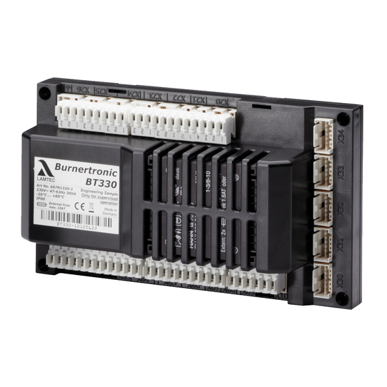
Functional Description Functional Description BT300 combines the benefits of an electronic fuel/air ratio control system with up to three mo- torised actuator elements and optional modules like an analogue output for speed control of the combustion air fan with an electronic burner control unit. The leakage test, flame monitor- ing system, power control unit and (optional) CO/O controller for control and optimisation of an oil or gas-fired forced-draught burner are all integrated.
-
Page 15: Operating Control And Displays
Operating Control and Displays Operating Control and Displays UI300 User Interface Display BACK key Cursor keys ENTER key Fig. 5-1 User Interface Display The display shows in pictograms: • the menu structure • operating status • parameters • error messages Back key Jump to previous window.
-
Page 16: Menu Functions
Operating Control and Displays Menu Functions The menu is divided into three paths: INFO MANUAL SETTINGS INFO Select INFO path for information about the following: • Burner • Faults/Fault history • Software version • Display of check sums • Serial number •…
-
Page 17: Main Menu
Operating Control and Displays Main Menu INFORMATION menu path [selected] Display of fuel type Bar graph of internal firing-rate in % (0 — 100) MANUAL menu path Access level 2 SETTINGS menu path Window number Fig. 5-2 Main menu 1. Use cursor keys to select a menu and press ENTER to confirm.
-
Page 18: Recall Fault History
Operating Control and Displays 2. Use keys to select menu and press ENTER to confirm. The display shows the «Display operating hours» menu window. Pictogram operating hours Total number of operating hours (device connected to mains voltage) No. of operating hours, oil operation No.
-
Page 19: Software Version
Operating Control and Displays Error code-display pictogram Fault code (Last 10 faults are stored, no. 01 is the latest fault) Diagnostic code 1 Diagnostic code 2 No. of operating hours when fault has oc- cured Fig. 5-8 Fault history menu NOTICE! Information concerning fault and diagnostic codes you may find in the list of fault codes.
-
Page 20: Display Of Check Sums
Operating Control and Displays 5.4.4 Display of Check Sums Display check sum 1. Use cursor keys to select menu and press ENTER to confirm. The display shows «CRC16 check sums» menu. Check sums pictogram Check sum, access level 0 Check sum, access level 1 Check sum, access level 2 Check sum, access level 4 Fig.
-
Page 21: Positions Of Actuators
Operating Control and Displays 5.4.6 Positions of Actuators Display positions of actuators 1. Use the cursor keys to select menu and press ENTER to confirm. The display shows the «Actuators» menu. Actuator pictogram Actuator channel 1 (oil) Actuator channel 2 (air) Actuator channel 3 (oil) Optional channel (OFF;…
- Page 22
Operating Control and Displays Digital inputs pictogram Jump to next page Fuel selection oil [no] Fuel selection gas [yes] Burner start [yes] — terminal X10 Fig. 5-14 Page 1 of inputs menu NOTICE! Signals of points 3 and 4 are «logical» signals and not «physical» ones. Background informa- tion: Some signals may have more than one source (terminal, LSB, field buses, parameters). -
Page 23: Digital Outputs
Operating Control and Displays NOTICE! Signals of points 4 and 5 in Fig. 5-15 Page 2 of inputs menu are «logical» signals, not «physi- cal». The BT320/330 supports either oil or gas operation, but cannot be switched. Therefore no separate signals for the oil or gas safety interlock chain are generated. The signal on ter- minal X06 is thus generally known as burner‘s safety interlock chain.
- Page 24
Operating Control and Displays Call up 2 page of outputs 1. Use the cursor keys to select the next page and press ENTER to confirm. The display shows «Page 2 digital outputs» menu: Digital outputs pictogram Jump to previous page Jump to next page Oil valve 1 [on] — terminal X01 Oil valve 2 [off] — terminal X02… -
Page 25: Manual Menu Path
Operating Control and Displays Manual Menu Path MANUAL Select MANUAL path to carry out actions as follows: Switching burner ON and OFF Presetting of burner firing-rate Display MANUAL menu 1. Use cursor keys to select path and press ENTER to confirm. The display shows the «Manual operation»…
-
Page 26: Settings Menu Path
Operating Control and Displays Settings Menu Path Display SETTINGS menu 1. Use cursor keys to select menu and press ENTER to confirm. The display shows the menu overview. Password pictogram (selected) Delete curves Display program settings Firing-rate controller settings Configuration of read-out actuator outputs Password settings Curve settings…
-
Page 27: Program Sequence
Operating Control and Displays 5.6.2 Program Sequence Configure program sequence 1. Use cursor keys to select menu and press ENTER to confirm. The display shows the program sequence overview. Duration of pre-ventilation [selected] Pilot burner oil operation Duration of post-ventilation Valve leakage test Pilot burner gas operation Fig.
- Page 28
Operating Control and Displays UI300 pictogram BT300 pictogram Cancel (backwards) Parameter number UI300 Parameter number UI300 Transfer by pressing ENTER (flashing) Value for UI300 Fig. 5-27 Secure data transfer Value for BT300 NOTICE! Apply value only if the values for UI300 and BT300 are identical! The parameter value must be confirmed by pressing ENTER within the countdown (8 s)! 5. - Page 29
Operating Control and Displays Pictogram UI300 Pictogram BT300 Parameter number UI300 Parameter number BT300 Pictogram apply parameters Value BT300 Value UI300 Fig. 5-29 Display of invalid data transfer Set duration of post-ventilation 1. Use cursor keys to select menu and press ENTER to confirm. - Page 30
Operating Control and Displays NOTICE! You require access level 2 to make settings in this function! Accept or discard the entry! Activate valve leakage test prior to ignition 1. Use cursor keys to select menu and press ENTER to confirm. 2. - Page 31
Operating Control and Displays Valve leakage test period 1. Use cursor keys to select menu and press ENTER to confirm. The display shows the valve leakage test period menu. Valve leakage test period pictogram Set valve leakage test period Press ENTER to accept settings Fig. - Page 32
Operating Control and Displays Pilot burner in oil operation pictogram Activate pilot burner in oil operation Press ENTER to accept settings Fig. 5-36 Pilot burner in oil operation menu NOTICE! You require access level 2 to make settings in this function! Accept or discard the entry! Configuration of actuating outputs 1. - Page 33
Operating Control and Displays 2. Use cursor keys to set firing-rate point and press ENTER to confirm. Set-point channel 1 is chosen (displayed inversely). 3. Use cursor keys to set channels’ actuator position. 4. Use cursor keys to switch to next channel. 5. - Page 34
Operating Control and Displays NOTICE! During multi-stage operation, the following points are available: Ignition point 1 (first stage), 1 2 (valve switch-on point, second stage), 1 2 (valve switch-off point, second stage) 2 (second level), 2 3 (valve switch-on point, third stage), 2 … - Page 35
Operating Control and Displays Set staged oil operation — transition from 1 to 2 stage Display valve switch-on point, 2 stage Setpoint, air damper position Actual value, air damper position Fig. 5-41 Transition from 1 to 2 stage 1. Select the setpoint for the air damper position and press ENTER to confirm. - Page 36
Operating Control and Displays The display shows the confirmation prompt: Back to previous menu Deleting values [selected] Proceed with deleting values Fig. 5-43 Confirmation prompt of deleting curves menu 2. Press ENTER The curve values will be deleted. The display shows the values deleted menu. Values deleted Fig. -
Page 37: Other Displays
Operating Control and Displays 5.6.3 Other Displays No connection between UI300 and BT300 UI300 User Interface pictogram No connection symbol BT300 burner control Fig. 5-46 No connection Display shown e.g. when using LSB remote software and communication between BT300 and UI300 is temporarily unavailable.
-
Page 38: Leakage Test For Main Gas Valves
Leakage Test for Main Gas Valves Leakage Test for Main Gas Valves Calculation Example An (approximate) formula for calculating the leakage test monitoring facility is summarised be- low: Definitions: GDW: gas pressure monitor gas-side safety shut-off device burner-side safety shut-off device barometric air pressure <…
-
Page 39: Leakage Test With Ventilation Via Roof
Leakage Test for Main Gas Valves Leakage Test with Ventilation Via Roof The leakage test checks whether or not the main gas valves are leakproof. For this purpose the gas pressure of the supply is analysed. As leakage test section (space between the two main valves) burns empty whenever the burn- er is switched off, this part is usually pressureless at start-up (gas pressure >…
- Page 40
Leakage Test for Main Gas Valves Fig. 6-1 Leakage test process diagram… -
Page 41: Exhaust Of Test Line Over The Roof
Leakage Test for Main Gas Valves Exhaust of Test Line Over the Roof NOTICE! Consider diameter of gas line in the roof ventilation. For ventilation, plug X02 is activated for 3 s. Make sure that this period is sufficient even for smallest ventilation line diameter! Fig.
-
Page 42: Technical Data
Technical Data Technical Data Technical Data BT300 Function Power supply: 230 V +10/-15 % 47-63 Hz 115 V +10/-15 % 47-63 Hz (on request) Maximum backup-fuse: 10 A slow-blow To be used only in a grounded power line network! Power consumption: max.
-
Page 43: Actuators 662R550
Technical Data Environmental Conditions Storage: Climatic conditions Class 1K3 according to DIN EN 60721-3 Mechanic conditions Class 1M2 according to DIN EN 60721-3 Temperature range -20 … +70 °C (no condensation) Electronic safety: Degree of protection (DIN EN 60529): BT300 – IP40 housing IP20 terminals UI300 –…
-
Page 44: Actuators 662R5001
Technical Data NOTICE! Damaging the 0,8 Nm actuator by opening the actuator. If you open the actuator at another part as the cover of the electric connection, you will dam- age the actuator. Do not open the actuator but at the cover of the electric connection. Actuators 662R5001…
- Page 45
Technical Data Environmental conditions 662R5001…/662R5003…/662R5009… Repeat frequency 2,5 kHz Electrical safety Protection class 2 as per DIN EN 60730 NOTICE! Damage of the actuator due to opening the actuators housing. You will damage the actuator, if you open the actuator’s housing at another (this affects actu- ators with 1,2, 3,0 and 9,0 Nm). - Page 46
Technical Data… - Page 48
The information in this publication is subject to technical changes. LAMTEC Meß- und Regeltechnik LAMTEC Leipzig GmbH & Co. KG Presented by: für Feuerungen GmbH & Co. KG Wiesenstraße 6 Portitzer Straße 69 D-69190 Walldorf D-04425 Taucha Phone: +49 (0) 6227 / 6052-0…
5
Operating Control and Displays
2. Use keys
Display burner start-ups
1. Use keys in System Information menu
The display shows the «Start-up counter» menu window.
5.4.2
Display burner faults
1. Use cursor keys
2. Use keys
to select menu
The display shows the «Display operating hours» menu window.
Fig. 5-5 Display «Operating hours»
to confirm.
Fig. 5-6 Display «Start-up counter»
The display shows «Fault history selection» menu.
Fig. 5-7 Fault history selection menu
to select menu
The display shows «Fault history» menu.
17
and press ENTER
1
Pictogram operating hours
2
Total number of operating hours
(device connected to mains voltage)
3
No. of operating hours, oil operation
4
No. of operating hours, gas operation
to select menu
1
Pictogram burner start-up
2
No. of burner start-ups, oil operation
3
No. of burner start-ups, gas operation
to select menu
and press ENTER
1
Burner fault pictogram [selected]
and press ENTER
to confirm.
and press ENTER
to confirm.
to confirm.
- Manuals
- Brands
- Lamtec Manuals
- Industrial Equipment
- BT300 BurnerTronic
- Quick reference
-
Contents
Table of Contents -
Bookmarks
Quick Links
Quick Reference for End Users
BurnerTronic BT300
Fault Codes for Software Version 3.9
Sensors and Systems for Combustion Engineering
www.lamtec.de
Related Manuals for Lamtec BurnerTronic BT300
Summary of Contents for Lamtec BurnerTronic BT300
-
Page 1
Quick Reference for End Users BurnerTronic BT300 Fault Codes for Software Version 3.9 Sensors and Systems for Combustion Engineering www.lamtec.de… -
Page 3: Table Of Contents
Table of Contents Table of Contents General Information …………3 Validity of these Instructions .
-
Page 4: General Information
• BT341 Faults NOTICE The LAMTEC burner controls use different methods to detect fault messages between main processor and watchdog processor: BT300/ETAMATIC/FMS/VMS/FA1: The bus transmission does not generally use different fault numbers to distinguish between watchdog processor and main processor faults. In order to distinguish the main processor fault messages from the watchdog processor fault messages, an offset of 10000 is added to the watchdog processor faults.
-
Page 5: List Of Fault Codes
List of Fault Codes List of Fault Codes Restarts according to TRD (P301 = 0 and P328 > 0) and EN676 (P301 = 2 and P328 > 0): The restart counter increases automatically at every burner start. The number of restarts is reset if •…
-
Page 6
List of Fault Codes P301 = 0 P301 = 2 Description Flame OFF during operation – Check curve settings – Check flame sensor – Check flame stability – Check positioning of the flame sensor – Check fuel valves – Check fuel supply –… -
Page 7
List of Fault Codes P301 = 0 P301 = 2 Description Flame signal is lost during the 2 safety time. – Check ignition point – Check spark igniter and pilot burner – Check flame sensor – Check flame stability – Check positioning of the flame sensor –… -
Page 8
List of Fault Codes P301 = 0 P301 = 2 Description Flame signal appears too early during ignition (pilot burner). If parameters 302 and 303 are set to value 3 or 4, only the ignition flame may be present during ignition (up to the begin- ning of the second safety time). -
Page 9
List of Fault Codes P301 = 0 P301 = 2 Description Different operation modes on both controllers Main processor and watchdog processor detect the digital input signal at slightly different times. A signal change is hap- pening only for such a short time that only one of the two pro- cessors detects it. -
Page 10
List of Fault Codes P301 = 0 P301 = 2 Description Monitoring band exceeded for too long. Channel – Check the damper for ease of movement. In the event of stiffness, clean the damper and make it smooth-running. – Check the function of the actuator without damper and replace if necessary. -
Page 11
List of Fault Codes P301 = 0 P301 = 2 Description A servo motor cannot find the reference position. Channel – Check the damper’s smooth-running to the reference position. (see chapter Adjusting of the Actuators in the BT300 manual print no. DLT1201). –… -
Page 12
List of Fault Codes P301 = 0 P301 = 2 Description Maximum permissible CO voltage exceeded CO Probe voltage +1V Offset Cold start may have been interrupted Probes not yet ready for use – Remove probe and check in air: Replace the probe if necessary –… -
Page 13
List of Fault Codes P301 = 0 P301 = 2 Description Program monitoring time (FAT) exceeded. Indication number Description see chapter 4 Assignment of the Programme Monitoring Time — Fault 600 A fault occurs during valve leakage test: Gas pressure is still present. -
Page 14
List of Fault Codes P301 = 0 P301 = 2 Description 1 *1) 1 *1) Invalid drop of the safety interlock chain system – Check contacts and wiring of the safety interlock chain. 1 *1) 1 *1) Invalid drop of the safety interlock chain gas –… -
Page 15
List of Fault Codes P301 = 0 P301 = 2 Description Optional Oil pressure is too low. – Make sure that oil is available. – Check oil pressure. – Check oil pressure switch. – Check oil filter – Check oil regulator Invalid change of the operation mode Fault during an internal self-test. -
Page 16
List of Fault Codes P301 = 0 P301 = 2 Description Spark igniter is on for too long. Up to version 3.8.0.0, the maximum switch-on time is calculated from different parameters of the BT300. From version 3.9.0.0, this time is set in parameter 338. 721- Internal fault –… -
Page 17
List of Fault Codes P301 = 0 P301 = 2 Description Valve leakage test: Main gas valve 1 is leaking. Main valve 1 is leaking (see BT300 manual DLT1205 chapter Valve leakage check of main valves). – Check the function of the gas pressure switch. –… -
Page 18
List of Fault Codes P301 = 0 P301 = 2 Description BT300 leaves SETTING mode automatically after 24 hours. The BT300 has a hard coded time out of 24 hours for setting the burner. This Timeout has expired. – Reset fault. –… -
Page 19
List of Fault Codes P301 = 0 P301 = 2 Description Internal fault Channel – Reset fault – If the fault still exists: Send error number and diagnostic code to the technical support. – Replace the device Directly controlled channel runs to an invalid position Channel + set point position… -
Page 20
EN 14459 allows only 4 remote fault resets every 15 min. The fault reset is monitored by LSB Remote Software, UI300, LAMTEC SYSTEM BUS and field bus. Exceeding the num- ber of fault resets causes the fault shot-down 889 and further remote fault resets are ignored. -
Page 21
List of Fault Codes P301 = 0 P301 = 2 Description Internal fault – Reset fault – If the fault still exists: Send error number and diagnostic code to the technical support. – Replace the device DFM: Fuel selection relay is defective or no/inconsistent feedback Invalid fuel selection in the DFM or inconsistent feedback from DFM. -
Page 22: Assignment Of Configuration Fault 107
Assignment of Configuration Fault 107 Assignment of Configuration Fault 107 Description Too many channels are activated. No channel at all is configured. Permanent spark igniter is configured (P302, P303), but no pilot flame monitoring device is present (P 800). Pre-purge suppression by external signal is not implemented. Fuel change by OFF and an unlimited post purge time is configured.
-
Page 23
Assignment of Configuration Fault 107 Description Configuration of the controllers incorrect: 1 = O trim is inactive, but the O correctional range is not 0 2 = CO controller is inactive, but the CO correctional range is not 0 3 = CO controller is inactive Requirements: At least one of the monitors that can be activated by parameter P225, P244 or P241 must be ON 4 = Safe O… -
Page 24: Assignment Of The Programme Monitoring Time — Fault 600
Assignment of the Programme Monitoring Time — Fault 600 Assignment of the Programme Monitoring Time — Fault 600 Description No effects of the CO/O controller The number of 250 000 burner starts has exceeded Adjustment mode is active Fuel selection is missing Safety interlock chain system is open Air pressure is still pending Safety interlock chain oil is open…
-
Page 25
Assignment of the Programme Monitoring Time — Fault 600 Description 2005 Automatic restart 2006 CPI / POC signal was missing at the start-up… -
Page 26: Assignment Of Internal Fault 999
Assignment of Internal Fault 999 Assignment of Internal Fault 999 Description The signal at the terminals changes rapidly for several seconds (100 ms — 200 ms). Stabilise the signal: – Check wiring for loose contacts. – Check pressure switch: Is the pressure safely above or below the set pressure thus preventing the pressure switch from oscillating? Terminal X.10.2 = burner ON Terminal X.10.1 = fault reset…
-
Page 27
Assignment of Internal Fault 999 Description Relay contact jams, does not drop or is controlled externally. – Disconnect the plug of the affected relay output from the BT300 and check whether the error is still present. If yes: Replace the device. If no: Search for an external source of malfunction. -
Page 28: Assignment Of Co/O 2 Control Faults Or Information
Assignment of CO/O Control Faults or Information Assignment of CO/O Control Faults or Information NOTICE Depending on the parameter settings, either O trim is deactivated or a fault switching of the burner is triggered (P 142). Factory setting: P 142 = 0 (CO/O control is inactive, burner is not switched off) ot = O control temporarily deactivated — automatic reset if values OK again.
-
Page 29
Assignment of CO/O Control Faults or Information CO faults — Fault description information 0004 fault No probe dynamics — O trim is deactivated (P118) No probe dynamics can be detected. – Correction range in BT300 too small or set to ’0’ 0 = Default setting. -
Page 30
Assignment of CO/O Control Faults or Information faults — Fault description information 0018 fault Internal fault: O setpoint curve is incorrect. – Reset fault – If the fault still exists: Send error number and diagnostic code to the technical support. –… -
Page 31
0040 CO fault There is no CO edge information available on the LAMTEC SYSTEM BUS. Lambda Transmitter is incorrectly configured or not connected to LSB. LSB connection is twisted. Lambda Transmitter is not in measuring mode (malfunction/cold start). -
Page 32
Assignment of CO/O Control Faults or Information Fault/ Comment informa- tion 0043 CO fault Cell resistance of the CO sensor is outside the monitoring range. The probe is too cold. Heating capacity is too low – Check wiring for probe heating and correct if necessary. –… -
Page 33
Assignment of CO/O Control Faults or Information Fault/ Comment informa- tion 0052 CO fault The CO edge signal is not plausible. The CO edge signal was present constantly for more than 60 s. The controller cannot control out of the CO. –… -
Page 34
The information in this publication is subject to technical changes. LAMTEC Meß- und Regeltechnik für Feuerungen GmbH & Co. KG Josef-Reiert-Straße 26 D-69190 Walldorf Telefon: +49 (0) 6227 6052-0 info@lamtec.de Telefax: +49 (0) 6227 6052-57 www.lamtec.de Print no. | Copyright 2022…
BGN
-
BGN 26 W UNI 10850010 0 19960104
-
BGN 17 W 15800010 2 19970320
-
BGN 17 15850010 1 19970320
-
BGN 26 W 15900010 3 19970320
-
BGN 26 15950010 2 19970320
-
BGN 50 16050010 3 20040824
BGN DSPGN ME
-
BGN 250 DSPGN ME 16790020 1 20130912
-
BGN 300 DSPGN ME 16840020 3 20140801
-
BGN 350 DSPGN ME 16890020 3 20140801
BGN LX
-
BGN 300 LX 15270010 2 20120625
-
BGN 300 LX V 15270015 1 20071005
-
BGN 390 LX 15290010 2 20120625
-
BGN 390 LX V 15290015 0 20070917
BGN MC
-
BGN 250 MC 16800010 1 20140618
-
BGN 300 MC 16850010 2 20140801
-
BGN 350 MC 16900010 2 20151030
-
BGN 450 MC 16940010 1 20140401
-
BGN 510 MC 16970010 1 20150220
BGN ME
-
BGN 450 ME 16950010 0 20130909
-
BGN 510 ME 16980010 1 20150220
BGN P
-
BGN 17 P 11600010 1 19930924
-
BGN 17 P UNI 11640010 0 19951221
-
BGN 17 PW UNI 11650010 0 19960105
-
BGN 23 PW 11750010 1 19930927
-
BGN 23 P UNI 11780010 0 19960102
-
BGN 23 P 15960010 1 19930924
BT DSG 4T
-
BT 250 DSG 4T 31310010 0 20070122
-
BT 300 DSG 4T 31510010 0 20070202
-
BT 300 DSG 4T Cerniera 31510011 1 20081101
BT DSN 4T
-
BT 40 DSN 4T 2058010 6 20160407
-
BT 50 DSN 4T 2061010 7 20160407
-
BT 75 DSN 4T 2071010 8 20160407
-
BT 100 DSN 4T 2076010 7 20160407
-
BT 120 DSN 4T 2081010 5 20150101
-
BT 120 DSN 4T Cerniera 2081011 3 20150101
-
BT 180 DSN 4T 2086010 7 20141115
-
BT 180 DSN 4T Cerniera 2086011 1 20050606
-
BT 250 DSN 4T 2101010 5 20080321
-
BT 250 DSN 4T Cerniera 2101011 0 20021120
-
BT 350 DSN 4T 2121010 5 20120622
-
BT 350 DSN 4T Cerniera 2121011 4 20120622
-
BT 300 DSN 4T 2131010 3 20061220
-
BT 300 DSN 4T Cerniera 2131011 1 20061227
BT DSNM-D
-
BT 75 DSNM-D 2500010 4 20070901
-
BT 100 DSNM-D 2503010 3 20050110
-
BT 120 DSNM-D 2505010 4 20050110
-
BT 180 DSNM-D 2507010 4 20061220
-
BT 250 DSNM-D 2515010 4 20061215
-
BT 300 DSNM-D 2520010 4 20061220
-
BT 350 DSNM-D 2525010 3 20070101
BT DSPG
-
BT 75 DSPG 3510010 2 20040303
-
BT 100 DSPG 3514010 3 20051010
-
BT 120 DSPG 3518010 1 20000309
-
BT 180 DSPG 3522010 5 20150801
-
BT 300 DSPG 3530010 6 20150801
BT DSPN
-
BT 75 DSPN 2610010 6 20150801
-
BT 100 DSPN 2615010 5 20150801
-
BT 120 DSPN 2620010 5 20150801
-
BT 180 DSPN 2625010 6 20150801
-
BT 250 DSPN 2630010 7 20150801
-
BT 300 DSPN 2635010 7 20150801
-
BT 350 DSPN 2640010 5 20150801
BT SPN
-
BT 17 SPN 2040111 5 20141201
-
BT 35 SPN 2052110 6 20160407
BTG
-
BTG 3 17000010 5 20080201
-
BTG 6 17040010 8 20150803
-
BTG 11 17060010 8 20150803
-
BTG 15 17080010 3 20140115
-
BTG 20 17100010 4 20140115
-
BTG 28 17140010 3 20140115
-
BTG 12 17170010 1 20150803
-
BTG 12 L300 17170020 1 20150803
BTG LX
-
BTG 20 LX 15100010 4 20160201
BTG ME
-
BTG 20 ME 17120020 1 20120201
-
BTG 15 ME 17130020 1 20140115
-
BTG 28 ME 17160020 2 20160201
BTG P
-
BTG 3,6 P 17030010 8 20150803
-
BTG 6 P 17050010 7 20150803
-
BTG 11 P 17070010 8 20150803
-
BTG 15 P 17090010 3 20140115
-
BTG 20 P 17110010 5 20160201
-
BTG 28 P 17150010 4 20160201
BTL
-
BTL 3 35450010 6 20110601
-
BTL 3 H 35450011 6 20080601
-
BTL 3 L200 35450020 2 20110601
-
BTL 4 35490010 6 20150803
-
BTL 6 35510010 6 20150803
-
BTL 6 H 35510011 6 20150601
-
BTL 6 L275 35510020 3
-
BTL 10 35530010 6 20150803
-
BTL 10 H 35530011 6 20150803
-
BTL 10 L250 35530020 6 20150803
-
BTL 14 35610010 5 20110602
-
BTL 20 35630010 6 20110601
-
BTL 26 35650010 6 20160204
BTL P
-
BTL 4 P 35500010 5 20150803
-
BTL 6 P 35520010 4 20150803
-
BTL 10 P 35540010 5 20150803
-
BTL 10 P L250 35540020 6 20150803
-
BTL 14 P 35620010 5 20110602
-
BTL 20 P 35640010 6 20160204
-
BTL 26 P 35660010 6 20160204
COMIST
-
COMIST 20 54770010 2 20071120
-
COMIST 250 55110010 4 20090215
-
COMIST 300 55160010 4 20090215
COMIST DSPGM
-
COMIST 250 DSPGM 5358050 5 20150615
-
COMIST 300 DSPGM 5360050 5 20150615
COMIST DSPNM
-
COMIST 180 DSPNM 5428010 4 20150615
-
COMIST 250 DSPNM 5430050 5 20150615
-
COMIST 300 DSPNM 5432050 5 20150615
COMIST N
-
COMIST 72 N 55380010 2 20141201
-
COMIST 122 N 55410010 2 20070110
COMIST NM
-
COMIST 180 NM 55460010 1 20141104
-
COMIST 300 NM 55560010 5 20130710
GI DSPG
-
GI 350 DSPG 6501010 5 20151015
-
GI 420 DSPG 6506010 7 20150801
-
GI 510 DSPG 6511010 7 20130710
-
GI 1000 DSPG 6521010 4 20120626
GI DSPN-D
-
GI 350 DSPN-D 6533010 9 20150801
-
GI 420 DSPN-D 6538010 5 20150801
-
GI 510 DSPN-D 6543010 7 20150801
-
GI 1000 DSPN-D 6553010 5 20081210
GI LX
-
GI 1000 LX 15360010 4 20091001
GI LX ME
-
GI 1000 LX ME 66570050 3 20091001
GI MIST DSPGM
-
GI-MIST 350 DSPGM 6675050 5 20120625
-
GI-MIST 420 DSPGM 6678050 3 20120625
-
GI-MIST 510 DSPGM 6681050 3 20120625
-
GI-MIST 1000 DSPGM 6687010 3 20100210
GI MIST DSPNM-D
-
GI-MIST 350 DSPNM-D 6705050 4 20081101
-
GI-MIST 420 DSPNM-D 6708050 2 20070101
-
GI-MIST 510 DSPNM-D 6711050 2 20070101
-
GI-MIST 1000 DSPNM-D 6717010 5 20100210
MINICOMIST
-
MINICOMIST 7 54700010 5 20160225
-
MINICOMIST 11 54730010 5 20160225
RINOX L
-
RINOX 35 L 35470050 2 20071201
-
RINOX 60 L 35510050 0
RINOX L2
-
RINOX 60 L2 35520050 1 20070404
-
RINOX 190 L2 35640050 1 20070404
SPARK
-
SPARK 35 W 3070010 3 20110701
-
SPARK 35 3071010 3 20110701
SPARK DSG
-
SPARK 35 DSGW 3075010 5 20110701
-
SPARK 35 DSG 3076010 6 20141010
SPARK LX
-
SPARK 35 LX 33960010 0 20040202
SPARKGAS
-
SPARKGAS 30 W 15680010 3 20070201
-
SPARKGAS 30 15700010 3 20070202
SPARKGAS P
-
SPARKGAS 30 PW 15690010 4 20070201
-
SPARKGAS 30 P 15710010 6 20110110
-
SPARKGAS 30 P L500 15710030 7 20070201
TBG
-
TBG 45 17200010 2 20110601
-
TBG 60 17270010 3 20110602
-
TBG 35 17320010 3 20160303
TBG LX ME
-
TBG 110 LX ME 17600020 1 20120401
-
TBG 140 LX ME 17670020 0 20120402
-
TBG 200 LX ME 17740020 0 20121018
TBG LX PN
-
TBG 110 LX PN 17590010 1 20080304
-
TBG 110 LX PN V 17590015 0 20080909
-
TBG 140 LX PN 17660010 0 20080303
-
TBG 200 LX PN 17730010 1 20080404
-
TBG 200 LX PN V 17730015 0 20080909
TBG MC
-
TBG 45 MC 17240010 4 20160513
-
TBG 60 MC 17310010 3 20160513
-
TBG 35 MC 17360010 1 20160203
-
TBG 85 MC 17540010 1 20140618
-
TBG 120 MC 17610010 0 20130508
-
TBG 150 MC 17680010 0 20130508
-
TBG 210 MC 17750010 0 20130508
-
TBG 260 MC 17760010 2 20160801
-
TBG 480 MC 67190010 1 20150519
-
TBG 800 MC 67230010 2 20160322
-
TBG 1100 MC 67450010 2 20160101
-
TBG 1600 MC 67490010 3 20160909
TBG ME
-
TBG 45 ME 17230020 0 20120601
-
TBG 60 ME 17300020 0 20120601
-
TBG 85 ME 17500020 0 20121001
-
TBG 120 ME 17570020 0 20121001
-
TBG 150 ME 17640020 1 20130611
-
TBG 210 ME 17710020 1 20130611
-
TBG 260 ME 17770010 1 20150403
-
TBG 480 ME 67180010 2 20150519
-
TBG 600 ME 67200010 9 20160322
-
TBG 800 ME 67220010 9 20160323
-
TBG 1100 ME 67440010 0 20130606
-
TBG 1600 ME 67480010 1 20150707
TBG P
-
TBG 45 P 17210010 1 20090701
-
TBG 60 P 17280010 4 20120401
-
TBG 35 P 17330010 5 20160303
-
TBG 85 P 17480010 4 20120401
-
TBG 120 P 17550030 1 20140618
-
TBG 150 P 17620030 1 20150201
-
TBG 210 P 17690030 0 20111207
TBG PN
-
TBG 45 PN 17220010 1 20090701
-
TBG 60 PN 17290010 2 20110601
-
TBG 60 PN V 17290020 0 20121018
-
TBG 35 PN 17340010 3 20160303
-
TBG 85 PN 17490010 3 20080303
-
TBG 85 PN V 17490020 0 20121030
-
TBG 120 PN 17560010 2 20080801
-
TBG 150 PN 17630010 2 20070505
-
TBG 210 PN 17700010 2 20120401
TBG PV
-
TBG 45 PV 17210020 1 20120614
-
TBG 60 PV 17280020 1 20110311
-
TBG 85 PV 17480020 0 20110404
TBL LX
-
TBL 45 LX 35730010 1 20110701
TBL P
-
TBL 45 P 400 35710015 3 20160303
-
TBL 45 P DACA 35710110 1 20110701
-
TBL 60 P 35750010 5 20160303
-
TBL 60 P DACA 35750110 4 20120401
-
TBL 85 P 35800010 3 20120401
-
TBL 85 P DACA 35800110 3 20120401
-
TBL 105 P 35850010 3 20120401
-
TBL 105 P DACA 35850110 2 20120401
-
TBL 130 P 35900010 3 20120401
-
TBL 130 P DACA 35900110 0 20070222
-
TBL 160 P 35950010 3 20120401
-
TBL 160 P DACA 35950110 2 20120401
-
TBL 210 P 36000010 2 20121030
TBML MC
-
TBML 50 MC 56450010 3 20150707
-
TBML 80 MC 56490010 5 20141107
-
TBML 120 MC 56530010 4 20141031
-
TBML 160 MC 56570010 4 20141031
-
TBML 200 MC 56610010 3 20141031
TBML ME
-
TBML 50 ME 56460010 3 20150707
-
TBML 80 ME 56500010 4 20141031
-
TBML 120 ME 56540010 3 20141031
-
TBML 160 ME 56580010 4 20141031
-
TBML 200 ME 56620010 3 20141031
-
TBML 350 ME 56710010 0 20140404
TBML P
-
TBML 60 P 56470010 2 20140901
-
TBML 150 P 56550010 2 20141031
Узлы горелок
-
Газовые рампы
-
Газовая рампа 71 tav71 1
-
Газовая рампа B19 19990025 0 19920901
-
Газовая рампа B37 19990008 0 19921209
-
Газовая рампа B39 19990009 0 19930927
-
Газовая рампа B41 19990022 0 19940616
-
Газовая рампа B43 19990023 0 19940616
-
Газовая рампа B77 19990002 0 19930310
-
Газовая рампа B89 19990018 0 19951006
-
Газовая рампа B98 19990004 0 19921209
-
Газовая рампа B99 19990005 1 19951221
-
Газовая рампа B101 19990020 1 19930924
-
Газовая рампа B102 19990021 0 19940124
-
Газовая рампа B103 19990019 0 19951222
-
Газовая рампа B104 19990024 0 19930324
-
Газовая рампа B106 19990011 0 19960103
-
Газовая рампа B246 901129 2 20070401
-
Газовая рампа B247 901093 1 20041027
-
Газовая рампа B247 901093 2 20070401
-
Газовая рампа B248 901135 1 20041027
-
Газовая рампа B248 901135 2 20070401
-
Газовая рампа B252 tavB252 3 20100210
-
Газовая рампа B260 901148 1 20040824
-
Газовая рампа B312 6010079 0 20090127
-
Газовая рампа T01 23859 1
-
-
Газовые клапаны
-
Газовый клапан T01 23026 1
-
-
Панели управления
-
Панель управления C76 901114 3 20070110
-
Панель управления C92 900793 3 20120621
-
Панель управления C138 901065 2 20040824
-
Панель управления C145 900746 5 20120401
-
Панель управления C146 900022 4 20120401
-
Панель управления C147 900768 4 20120401
-
Панель управления C149 900143 5 20120401
-
Панель управления C168 900367 2 20040303
-
Панель управления C169 tavС169 1 20000308
-
Панель управления C170 900090 3 20120401
-
Панель управления C171 900094 3 20120625
-
Панель управления C179 17229 5 20120401
-
Панель управления C181 R15997 4 20120401
-
Панель управления C182 57229 3 20041015
-
Панель управления C182 57229 4 20120401
-
Панель управления C183 57228 2 20010801
-
Панель управления C183 57228 3 20041104
-
Панель управления C184 13303 3 20041104
-
Панель управления C185 13529 6 20120622
-
Панель управления C186 900460 3 20070901
-
Панель управления C187 900109 3 20041104
-
Панель управления C188 900056 3 20061220
-
Панель управления C189 900065 3 20061215
-
Панель управления C190 900124 3 20061220
-
Панель управления C191 900420 3 20070101
-
Панель управления C193 900348 4 20120401
-
Панель управления C194 900101 4 20120621
-
Панель управления C195 900071 5 20120401
-
Панель управления C196 900068 4 20120709
-
Панель управления C197 900118 4 20120625
-
Панель управления C198 900815 4 20120401
-
Панель управления C204 49595 4 20160225
-
Панель управления C205 901108 1 20141104
-
Панель управления C208 900817 3 20120401
-
Панель управления C209 900601 3 20120625
-
Панель управления C211 901110 3 20120709
-
Панель управления C217 901098 3 20061212
-
Панель управления C220 900714 3 20120625
-
Панель управления C260 900134 2 20120625
-
Панель управления C261 900664 2 20120625
-
Панель управления C262 901167 3 20120625
-
Панель управления C263 901152 1 20041027
-
Панель управления C264 901176 2 20080720
-
Панель управления C268 901203 1 20041104
-
Панель управления C270 22010026 1 20031010
-
Панель управления C318 20030011 1 20071120
-
Панель управления C319 901164 3 20121213
-
Панель управления C329 901199 0 20040303
-
Панель управления C350 22030184 1 20070202
-
Панель управления C392 24010025 2 20120401
-
Панель управления C394 24010028 1 20070404
-
Панель управления C394 24010028 2 20120401
-
Панель управления C402 12120112 1 20120625
-
Панель управления C408 12100006 0 20070122
-
Панель управления C409 24060020 2 20120401
-
Панель управления C411 24060036 0 20070303
-
Панель управления C411 24060036 2 20120401
-
Панель управления C425 12010158 0 20070914
-
Панель управления C435 25010045 2 20120401
-
Панель управления C437 25010017 2 20120401
-
Панель управления C438 25040007 3 20120401
-
Панель управления C439 25030011 1 20090701
-
Панель управления C440 25020029 1 20110701
-
Панель управления C443 25030023 1 20090701
-
Панель управления C445 25030030 2 20110515
-
Панель управления C448 24010049 0 20080909
-
Панель управления C452 25040026 2 20110515
-
Панель управления C453 25040020 1 20090701
-
Панель управления C454 22030239 0 20060508
-
Панель управления C457 25020036 1 20110701
-
Панель управления C480 20040022 1 20110701
-
Панель управления C486 20040006 1 20110701
-
Панель управления C487 20040025 1 20110701
-
Панель управления C498 25040043 0 20110210
-
Панель управления C500 24020029 0 20110404
-
Панель управления C503 27010043 2 20130606
-
Панель управления C503 27010043 4 20131023
-
Панель управления C509 24030055 0 20111207
-
Панель управления C509 24030055 1 20120401
-
Панель управления C513 22040066 0 20100210
-
Панель управления C514 12120109 2 20130901
-
Панель управления C514 12120109 3 20141111
-
Панель управления C517 25040057 0 20110515
-
Панель управления C518 22040064 0 20100210
-
Панель управления C523 24020036 0 20121001
-
Панель управления C526 24100075 3 20141106
-
Панель управления C532 12120179 0 20130201
-
Панель управления C532 12120179 1 20140401
-
Панель управления C537 24030066 0 20130508
-
Панель управления C539 27020019 0 20130606
-
Панель управления C540 24100097 1 20140911
-
Панель управления C549 12150001 0 20140211
-
Панель управления C551 12150002 0 20140225
-
Панель управления C553 12130047 0 20140404
-
Панель управления C554 25050043 0 20140418
-
Панель управления C557 25030044 0 20140505
-
Панель управления C558 22020003 1 20120626
-
Панель управления C560 24100105 0 20140606
-
Панель управления C574 28020054 0 20150206
-
Панель управления C575 24050022 0 20150202
-
Панель управления C576 11020108 1 20120401
-
Панель управления C578 24050012 0 20150303
-
Панель управления C586 28020041 0 20150707
-
Панель управления C592 24020035 0 20121030
-
Панель управления C595 10150053 0 20141201
-
Панель управления C595 10150053 1 20160407
-
Панель управления C600 25040081 0 20160513
-
Панель управления C601 25030055 0 20160513
-
-
Узлы модуляции
-
Узел модуляции A22 16279 2 20041027
-
Узел модуляции A22 16279 3 20110501
-
Узел модуляции A22 16279 4 20150615
-
Узел модуляции A24 16251 1 20010214
-
Узел модуляции A24 16251 2 20051010
-
Узел модуляции A24 16251 4 20150801
-
Узел модуляции A30 22010024 0 20011112
-
Узел модуляции A37 22040019 0 20040308
-
Узел модуляции A45 24030054 0 20111212
-
Узел модуляции A45 24030054 2 20150201
-
Узел модуляции A46 12120141 1 20140618
-
Узел модуляции A49 24100074 2 20141106
-
Узел модуляции A51 25050019 2 20140618
-
Узел модуляции A53 24030065 0 20130508
-
Узел модуляции A53 24030065 1 20140618
-
Узел модуляции A55 27020013 1 20140510
-
Узел модуляции A63 12140049 2 20140123
-
Узел модуляции A64 12150014 1 20131202
-
Узел модуляции A65 25050028 1 20140419
-
Узел модуляции A66 25040070 1 20140807
-
Узел модуляции A67 24100104 0 20140606
-
Узел модуляции A68 28020031 1 20150801
-
Узел модуляции A69 20040033 0 20140909
-
Узел модуляции A70 24050023 0 20150202
-
-
Узлы распыливания
-
Узел распыливания B164 900084 2 20070401
-
Узел распыливания D3 27665 2 20040303
-
Узел распыливания D4 10140010 3 20040303
-
Узел распыливания D5 57070 3 20030520
-
Узел распыливания D20 44115 3 20030630
-
Узел распыливания D20 44115 5 20130710
-
Узел распыливания D28 44100 2 20030626
-
Узел распыливания D31 39100 3 20040303
-
Узел распыливания D32 56059 1 20041104
-
Узел распыливания D35 17221 3 20041007
-
Узел распыливания D41 13271 4 20051111
-
Узел распыливания D44 37900 2 20010515
-
Узел распыливания D47 27835 4 20041007
-
Узел распыливания D53 12030028 2 20041104
-
Узел распыливания D57 14311 3 20051010
-
Узел распыливания D58 11020075 1 20041007
-
Узел распыливания D59 11020058 2 20041015
-
Узел распыливания D60 12050021 1 20041104
-
Узел распыливания D61 14050012 1 20041104
-
Узел распыливания D62 22010013 0 20011112
-
Узел распыливания D62 22010013 1 20130710
-
Узел распыливания D64 14050018 0 20030424
-
Узел распыливания D66 11080010 0 20030224
-
Узел распыливания D67 12030019 0 20030224
-
Узел распыливания D70 12040038 1 20051010
-
Узел распыливания D71 60112 2 20041115
-
Узел распыливания D72 22040007 0 20040308
-
Узел распыливания D72 22040007 1 20080916
-
Узел распыливания D76 12100004 0 20070202
-
Узел распыливания D77 12080005 0 20070202
-
Узел распыливания D78 12080012 0 20070202
-
Узел распыливания D81 11020087 1 20020101
-
-
Подогреватели жидкого топлива
-
Подогреватель жидкого топлива E1 27820 3 20041007
-
Подогреватель жидкого топлива E3 900850 2 20041015
-
Подогреватель жидкого топлива E4 900233 2 20041015
-
Подогреватель жидкого топлива E4 900233 3 20100401
-
Подогреватель жидкого топлива E21 900750 2 20100401
-
Подогреватель жидкого топлива E38 17227 4 20041007
-
Подогреватель жидкого топлива E39 tavE39 3 20060213
-
Подогреватель жидкого топлива E40 10150017 3 20041007
-
Подогреватель жидкого топлива E40 901162 4 20151105
-
Подогреватель жидкого топлива E41 37910 4 20070921
-
Подогреватель жидкого топлива E44 900095 2 20041015
-
Подогреватель жидкого топлива E46 900234 2 20041015
-
Подогреватель жидкого топлива E47 900235 2 20041015
-
Подогреватель жидкого топлива E51 900444 1 20041015
-
Подогреватель жидкого топлива E55 901127 1 20041015
-
Подогреватель жидкого топлива E56 900231 1 20041015
-
Подогреватель жидкого топлива E57 900822 1 20041015
-
Подогреватель жидкого топлива E59 901096 3 20041015
-
Подогреватель жидкого топлива E66 901156 1 20050606
-
Подогреватель жидкого топлива E67 900472 0 20030424
-
Подогреватель жидкого топлива E76 900399 1 20030401
-
Подогреватель жидкого топлива E81 15700054 0 20081210
-
-
Регуляторы давления жидкого топлива
-
Регулятор давления жидкого топлива H1 16230 2 20010801
-
Регулятор давления жидкого топлива H2 16325 2 20001114
-
Регулятор давления жидкого топлива H3 16336 2 20011115
-
Регулятор давления жидкого топлива H6 16320 2 20010214
-
Регулятор давления жидкого топлива H6 16320 3 20130710
-
Регулятор давления жидкого топлива H7 10160018 0 19970901
-
Регулятор давления жидкого топлива H7 10160018 1 20130710
-
Регулятор давления жидкого топлива H12 16400 0 20030825
-
-
Топливные насосы
-
Топливный насос F2 5060003 2 20070404
-
Топливный насос F3 5060044 1
-
Топливный насос F5 30750 1
-
Топливный насос F5 30750 2
-
Топливный насос F8 5060068 0 20061111
-
Топливный насос F9 31200 0 20070202
-
Топливный насос F10 R30752 0 20070222
-
Топливный насос F10 30752 0 20070222
-
Топливный насос L1 900030 3 20041104
-
Топливный насос L2 900452 3 20041104
-
Топливный насос L2 900452 4 20070901
-
Топливный насос L3 900053 5 20070202
-
Топливный насос L6 900011 4 20070203
-
Топливный насос L15 900700 4 20051027
-
Топливный насос L16 900036 4 20070302
-
Топливный насос L17 900039 3 20070202
-
Топливный насос L20 900451 1 20041104
-
Топливный насос L24 900341 3 20041104
-
Топливный насос L25 900849 3 20041105
-
Топливный насос L27 900322 2 20111115
-
Топливный насос L48 900004 4 20070202
-
Топливный насос L48 900004 6 20121212
-
Топливный насос L50 19807 2 20070202
-
Топливный насос L66 901161 2 20141201
-
Топливный насос L71 901211 0 20041104
-
Топливный насос L72 901212 0 20041104
-
Топливный насос L98 FS21201700L 0 20130606
-
-
Электромагнитные приводы узлов распыливания
-
Электромагнитный привод узла распыливания G1 tavG1 2 19970923
-
Электромагнитный привод узла распыливания G5 900002 1 20030701
-
Электромагнитный привод узла распыливания G6 900044 0 20010515
-
Электромагнитный привод узла распыливания G7 900618 0 20010605
-
Электромагнитный привод узла распыливания G8 900345 0 20010605
-
Электромагнитный привод узла распыливания G9 900029 1 20010620
-
Электромагнитный привод узла распыливания G10 22040033 1 20081115
-
Электромагнитный привод узла распыливания G11 6521010 1 20081115
-
-
Газовые дроссели
-
Газовый дроссель V4 20040010 2 20110110
-
Газовый дроссель V5 25040015 0 20090701
-
Газовый дроссель V7 25040036 0 20110210
-
Газовый дроссель V8 24020030 1 20110211
-
Газовый дроссель V9 27010075 1 20121213
-
Газовый дроссель V10 24030057 0 20111207
-
Газовый дроссель V10 24030057 1 20171002
-
Газовый дроссель V11 25040055 0 20120601
-
Газовый дроссель V12 24040041 0 20121001
-
Газовый дроссель V14 24100071 0 20121029
-
Газовый дроссель V16 25050020 0 20130301
-
Газовый дроссель V18 25040079 0 20140909
-
Газовый дроссель V18 25040079 1 20171002
-
Газовый дроссель V19 28020017 0 20150206
-
-
Гидроцелиндры
-
Гидроцелиндр M24 25020011 1 20090615
-