При работе в midas GTS NX или midas FEA NX может возникнуть предупреждение 4067. В этой статье разберём это предупреждение и наиболее частую причину его возникновения.
Предупреждение 4067 говорит пользователю о том, что в модели обнаружены лишние ограничения степеней свободы.
Рисунок 1. Предупреждение 4067 в логе расчёта
Но, как правило, следующим сообщением в логе расчёта пользователь видит сообщение «CORRESPONDING DEPENDENCIES ARE DISCARDED.», что говорит о том, что лишние закрепления отменяются.
Рисунок 2. Сообщение об исправлении модели
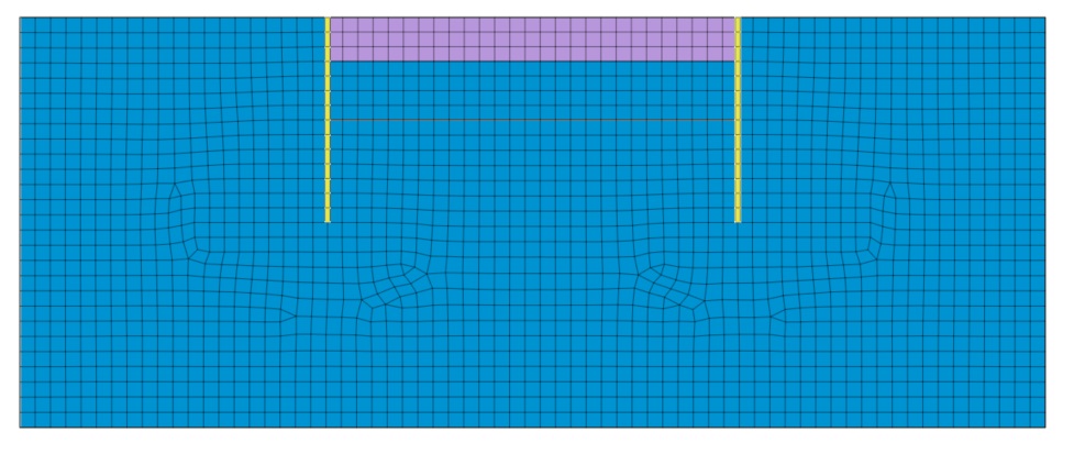
Таким образом, мы приходим к тому, что это предупреждение носит исключительно информационный характер и не влияет на ход и результат расчёта. Однако пользователь все равно должен понимать природу этого предупреждения, чтобы правильно анализировать возникшие предупреждения и делать выводы о работоспособности модели. Разберём самый частый сценарий возникновения этого предупреждения. Смоделируем двухмерную задачу разработки котлована. В модели имеется массив грунта, элементы ограждения котлована и набор конечных элементов, имитирующий выемку грунта.
Рисунок 3. Тестовая модель
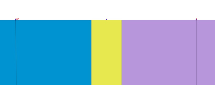
Как мы знаем, при корректно созданной модели мы имеем прямую узловую связь между всеми элементами. Это касается и элементов ограждения котлована. При этом мы имеем общий узел у элемента ограждения, грунта слева и справа от стенки.
Рисунок 4. Общий узел стенки и грунта
Для корректного моделирования, учёта отлипания и проскальзывания грунта по конструкции следует задавать интерфейсные элементы. Как мы знаем, при создании интерфейсов узлы элементов, на которые назначаются интерфейсы, расшиваются, связь осуществляется с помощью интерфейсных элементов. Для начальных стадий, где интерфейсы ещё отсутствуют, связь между узлами осуществляется с помощью элементов жестких связей «Rigid Link». При задании элементов интерфейсов и жестких связей у этих элементов так же, как и у всех остальных, формируются свойства. В случае с интерфейсными элементами, материалы и свойства формируются либо вручную, либо с помощью мастера. Свойства жестких связей формируются полностью автоматически.

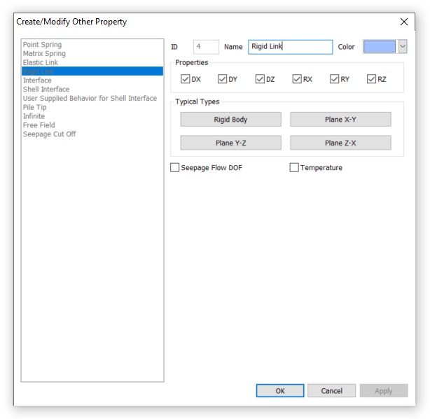
Разберём подробнее, какие настройки содержатся в свойствах «Rigid Link».
Рисунок 6. Свойства «Rigid Link»
Первый блок свойств «Properties» позволяет выбрать, какие именно закрепления будет вводить жесткая связь. По умолчанию активированы ограничения степеней свободы по всем 6 компонентам. Именно это является причиной предупреждения 4067 в тестовом примере. В двухмерной задаче присутствуют только 3 степени свободы. Поступательная составляющая по X и по Y (DX, DY) и вращательная составляющая вокруг глобальной оси Z (RZ). То есть из 6 компонентов могут быть использованы только 3. Именно об этом сообщает предупреждение 4067, указывая количество лишних закреплений. Таким образом, это предупреждение не является критичным и никак не влияет на результат. Лишние закрепления не используются.
Однако можно отключить лишние ограничения. Для этого можно вручную деактивировать лишние для 2D задачи компоненты (DZ, RX, RY). Либо воспользоваться предустановленными наборами компонентов в поле «Typical Types». В этом блоке можно выбрать, в какой плоскости выполняется работа в плоской задаче, либо пункт «Rigid Body» — для трехмерной. Работая в плоскости XY, выбрав соответствующий пункт «Plane X-Y», вы избежите предупреждения 4067, так как не вводятся лишние закрепления.
Последние две опции этого окна добавляют степень свободы по фильтрации (Seepage Flow DOF) и теплопереносу (Temperature). По умолчанию элементы жёстких связей не пропускают фильтрационный или тепловой поток. На это нужно обращать внимание, так как это может негативно влиять на результат расчёта в некоторых рассматриваемых случаях.
There are different types of errors in GTS NX. We have compiled them with their description and possible solution in this link: http://manual.midasuser.com/en_common/GTS%20NX/260/GTS_NX/Trouble_Shooting_Guide/Erro_code.htm
Creation date: 9/4/2016 10:16 AM
Updated: 9/4/2016 10:16 AM
При работе в midas GTS NX или midas FEA NX может возникнуть предупреждение 4067. В этой статье разберём это предупреждение и наиболее частую причину его возникновения.
Предупреждение 4067 говорит пользователю о том, что в модели обнаружены лишние ограничения степеней свободы.
Рисунок 1. Предупреждение 4067 в логе расчёта
Но, как правило, следующим сообщением в логе расчёта пользователь видит сообщение «CORRESPONDING DEPENDENCIES ARE DISCARDED.», что говорит о том, что лишние закрепления отменяются.
Рисунок 2. Сообщение об исправлении модели
Таким образом, мы приходим к тому, что это предупреждение носит исключительно информационный характер и не влияет на ход и результат расчёта. Однако пользователь все равно должен понимать природу этого предупреждения, чтобы правильно анализировать возникшие предупреждения и делать выводы о работоспособности модели. Разберём самый частый сценарий возникновения этого предупреждения. Смоделируем двухмерную задачу разработки котлована. В модели имеется массив грунта, элементы ограждения котлована и набор конечных элементов, имитирующий выемку грунта.
Рисунок 3. Тестовая модель
Как мы знаем, при корректно созданной модели мы имеем прямую узловую связь между всеми элементами. Это касается и элементов ограждения котлована. При этом мы имеем общий узел у элемента ограждения, грунта слева и справа от стенки.
Рисунок 4. Общий узел стенки и грунта
Для корректного моделирования, учёта отлипания и проскальзывания грунта по конструкции следует задавать интерфейсные элементы. Как мы знаем, при создании интерфейсов узлы элементов, на которые назначаются интерфейсы, расшиваются, связь осуществляется с помощью интерфейсных элементов. Для начальных стадий, где интерфейсы ещё отсутствуют, связь между узлами осуществляется с помощью элементов жестких связей «Rigid Link». При задании элементов интерфейсов и жестких связей у этих элементов так же, как и у всех остальных, формируются свойства. В случае с интерфейсными элементами, материалы и свойства формируются либо вручную, либо с помощью мастера. Свойства жестких связей формируются полностью автоматически.

Разберём подробнее, какие настройки содержатся в свойствах «Rigid Link».
Рисунок 6. Свойства «Rigid Link»
Первый блок свойств «Properties» позволяет выбрать, какие именно закрепления будет вводить жесткая связь. По умолчанию активированы ограничения степеней свободы по всем 6 компонентам. Именно это является причиной предупреждения 4067 в тестовом примере. В двухмерной задаче присутствуют только 3 степени свободы. Поступательная составляющая по X и по Y (DX, DY) и вращательная составляющая вокруг глобальной оси Z (RZ). То есть из 6 компонентов могут быть использованы только 3. Именно об этом сообщает предупреждение 4067, указывая количество лишних закреплений. Таким образом, это предупреждение не является критичным и никак не влияет на результат. Лишние закрепления не используются.
Однако можно отключить лишние ограничения. Для этого можно вручную деактивировать лишние для 2D задачи компоненты (DZ, RX, RY). Либо воспользоваться предустановленными наборами компонентов в поле «Typical Types». В этом блоке можно выбрать, в какой плоскости выполняется работа в плоской задаче, либо пункт «Rigid Body» — для трехмерной. Работая в плоскости XY, выбрав соответствующий пункт «Plane X-Y», вы избежите предупреждения 4067, так как не вводятся лишние закрепления.
Последние две опции этого окна добавляют степень свободы по фильтрации (Seepage Flow DOF) и теплопереносу (Temperature). По умолчанию элементы жёстких связей не пропускают фильтрационный или тепловой поток. На это нужно обращать внимание, так как это может негативно влиять на результат расчёта в некоторых рассматриваемых случаях.
New Features
midas GTS NX 2020(v1.1) has been released.
The following features and improvements have been added:
Partial Factor based on Euro Code
Partial factor which is derived from Euro Code (EN1997-1 Annex A) can be applied on the 2D model.
(Partial factor will be considered to materials which is containing the cohesion and friction angle and construction stage analysis with stress type)
Virtual Beam
It is creating the virtual beam from 2D/3D element and will be expressed with diagram for the result of virtual beam. Force can be found from virtual beam force after analysis with activating the mesh set of virtual beam under construction stage.
3D plane will be created on the normal direction of created virtual beam and force will be got from Local Direction force Sum of element which is on the same plane.
Considering Elastic Zone from Pile Element
It is considering the elastic zone which is using the pile interface on the 1D beam element from 2D/3D model.
There is plasticity without considering the elastic zone and will be occurred huge deformation. So, elastic zone will prevent to occur the plasticity in the area considering diameter of pile.
Improvement of Jointed Rock Mass model
The dilatancy angle and tensile strength have added to each joint. Also, Failure criteria of Mohr-Coulomb can be applied on intact.
PM4Sand model
It is developed to scheme the liquefaction using plastic theory based on effective stress. It is expanded to analysis with non-linear implicit based on the material model which is applied to liquefaction scheme using explicit method.
Elastic: It is nonlinear elastic behavior changing the elastic modulus with effective pressure(P) under Elastic zone. It needs to be selected with linear elastic or power law.
Rayleigh Damping Stiffness
It has added initial stiffness dependence method for Rayleigh damping process from damping force calculation.
Pretension Type (Multi-Stage Prestressing)
For Prestress > Pretension type, the load can be added or replaced under construction stage.
In case of pretension will analysis with external force. Previously, It is working with only add function under the activation step. But, User can add or replace the pretension from this newer version.
Improvement of Mode Combination with Sign
It has added the expression of sign for user convenience about the result from each ingredient.
Option 1. Principal mode from each direction
Option 2. Maximum mode (Absolute value)
Phreatic Line/Face
It can be verified phreatic line and face from seepage analysis result and check this result with others.
Estimate Unsaturated Property
The properties of saturated soil are inputted by test data and it is hard to conduct the test in real project due to the time and cost. From the newer version, the curve can be made by void ration, specific gravity, density and reference grain distribution from curve of grain distribution.
SRC Section DB
SRC(Steel Reinforced Concrete) can be defined under 1D element(truss, beam, embedded truss, embedded beam).
Automatically Calculation of H Section
It is calculating the torsional stress coefficient, effective shear area and shear stress coefficient automatically from selecting the database of H section, r1/r2 can be inputted additionally.
Control the Artificial Earthquake
Random Seed can apply to get same artificial earthquake.
Improvement of Loft Function
It has improved the loft function with new method. Loft function can use to section with hole.
(Previous method: direct loft between models, Newer version: lofting with center between models)
Label Location of Dynamic Nodal Load
The location of arrow from dynamic nodal load can be controlled. It can select Start, Middle, End position.
Improvement of Stage Bar from Post
If there are many subcase under post tree, the post function will work slowly so that it has improved.
The subcase will check off as a default after analysis. It needs check on to see the stage result.
Improvement of Prescribe Strain(Volumetric Strain)
Prescribe strain can be applying to linear static analysis, nonlinear static analysis, consolidation analysis and fully coupled analysis as well.
There is no strain component of z direction so that it has eliminated.
Improvement of Applying LDF
The error message has updated more correctly under stress-seepage analysis. The construction stage need to be constituted seepage analysis first under stress-seepage analysis. This stress-seepage analysis will be calculated pore pressure from seepage analysis to stress analysis.
ex) step 1. Seepage or Stress > step 2. Stress(Deactivate mesh & LDF) > step 3. Seepage (about step 2) > Step 4. Stress ← Analysis N/A
Step of LDF will be counted under stress stage only from stress-seepage analysis.
Words Amendment from Plastic Hardening Function
Plastic Hardening Function and Frictional Angle Hardening Curve are similar so that it has unified.
1) Mesh > Prop./CSys./Func. > Function > Plastic Hardening Curve Deleted
2) Nonlinear tab from MMC model > Friction Angle at shear > Hardening Function > Name has changed from Plastic Hardening Function to Frictional Angle Hardening Curve.
3) Hardening Curve’s table: Plastic Strain -> Equivalent Plastic Strain
Output of 2D Equivalent Linear Analysis
In case of 1 from all output step and step will be provided the history graph without considering Intermediate output of time step from the 2D equivalent linear analysis.
History graph contains interval of step and time under selecting the frequency of history output probes.
Mining Model Converter
DataMine SW(MicroMine, Leapfrog, etc.) model file can be converting to GTS NX file.
Downloads
You can download the latest GTS NX install via the MIDAS Software Download pages:
GTS NX 2020(v1.1) Installation Program
For more details and what technical issues have been solved, please read our release notes:
GTS NX 2020(v1.1) Release Notes
NX открыть родительский элемент в окне
Теги: NX
окружение:Win7 x64 , NX12 Описание сцены: Как показано на рисунке выше: компоненты _model1 и _model2 имеют компоненты _model3, а затем щелкните _model3 -> «открыть в окне». Затем найдит…
Конфигурация среды отладки NX проекта в среде TC
Теги: NX
содержание: Конфигурация среды отладки проекта NX в среде TC Тестовая образец среды: Win7 x64, tc11 (четыре слоя), nx12, vs2015, Метод отладки: Отладка от VS компилятора, не прикрепленный процесс (доп…
NX Progress Bar Production
Теги: NX
Окружающая среда:Win10, x64, VS2017, NX1907 Дата записи:2020/09/17 Цель:Внедрить следующий эффект изображения Идеи реализации: Объясните, что я обычно использую C ++ для разработки NX, но есть много о…
Сводка GMS
Теги: CTS GTS
Переведено изhttps://www.jianshu.com/p/7740b018a24d Я отсутствовал некоторое время, и я всегда хотел написать этот блог, но у меня нет времени. Недавно я свободен. Я просто подвел итог части тестовой …
NXOpen связанных
Теги: NX C++
Онлайн документ Вы можете найти GTAC и ввести соответствующую версию документации NX. Инструменты программирования в области Product содержат информацию, связанную с разработкой NXOpen. Чтобы просмотр…
UG NX: заказная ведомость материалов
Теги: UG NX
Ключевые моменты хорошего графикаЩелкните правой кнопкой мыши -> Сохранить как шаблон.: Таким образом, он может записать себя в следующий путь:C:Program FilesSiemensNX 10.0UGIItable_filestabl…
- Keep Running into Analysis Errors When Everything Looks Right?
It’s not uncommon for the analysts to run into the same analysis error after having checked the analysis set up a hundred times. It’s also common to find a nonlinear analysis not able to reach convergence after it has worked out perfectly in the linear domain. Most likely the issue is within meshing. Meshing and meshing control is an important step in FEM analysis, and computed FE results tend to be the most accurate when elements are compact, without great elongation, skew, or warping [1].
- What Causes Distorted Elements?
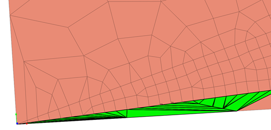
Element distortion can happen when portraying geometric irregularity. Using more compacted elements and finer mesh at those locations can help with improving the result accuracy. However, it’s not economical to use the same fine mesh throughout the geometry, because coarser meshes are sufficient to represent the geometrically simpler parts of the model. Coarser mesh is also sufficient when the load application is far enough from the geometry and the expected corresponding stress effect is trivial and causes insignificant deformation. Therefore, for models that have both fine and coarse meshes, element distortion can happen due to the mesh size transition. Figure 1 shows the distorted elements highlighted in green due to the transition from coarse to fine elements.
Figure 1. Distorted elements (highlighted in green) due to the transition from coarse to fine elements
Element distortion can also happen due to the connection between mesh sets. In FEM, object connectivity is utilized using nodal connectivity. Therefore, the simplest way to model two connecting objects is to merge the nodes at their connecting boundaries. However, when two mesh sets have different mesh sizes, the transition of mesh elements is needed.
- How to Check Element Quality?
Besides element distortion, the relative size between connected elements and the shape and quality of a mesh has a larger effect on the analysis results than its absolute size. Hence, after creating a mesh, it is important to check and modify the quality of the mesh.
Aspect Ratio
Aspect ratio is the length ratio between the width and length or the ratio of the longest side to the shortest side of a 2D element. For example, a square has the same width and length and therefore has an aspect ratio of 1. As a shape digresses from the square shape, the aspect ratio becomes smaller. A value closer to 1 is ideal. This ratio has a significant effect on the analysis result in and if the value is very small, it may be hard to obtain normal analysis results.
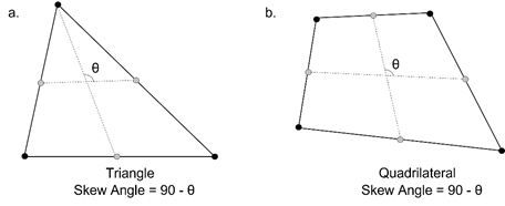
Skew Angle
Skew angle describes how much the shape digresses from the rectangular shape (90 degrees), measured in angles. A quadrilateral forms a 90-degree angle, the inclination angle is 0 degrees, and this value increases as the shape strays from the quadrilateral. For a solid element, the inclination angle is checked for each face and the smallest value is chosen as the inclination angle. A value closer to 0 is better. Figure 2 shows the skew angle of triangular and quadrilateral elements.
Figure 2. Skew angle calculation of triangular and quadrilateral elements in Midas FEA NX.
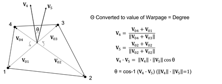
Warpage
Warpage evaluates how much the shape is out of the plane. For a quadrilateral 2D element with all nodes on the same plane, the value is 0. The value increases as the shape strays from the plane. For a solid element, the warpage is checked for each rectangular face and the smallest value is chosen as the warpage value. A value closer to 0 is better. This item has a significant effect on the analysis result and if the value is very large, it may be hard to obtain normal analysis results. Figure 3 shows how the warpage value is calculated.
Figure 3. Warpage value calculation for 2D quadrilateral elements in Midas FEA NX.
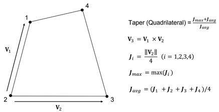
Taper
Taper calculates geometrically how much the quadrilateral digresses. It is not applied to triangular elements. A quadrilateral has a value of 1, and the value decreases as it digresses, meaning that it becomes closer to a triangular shape from its rectangular shape. For a solid element, the taper value is checked for each face and the smallest value is chosen as the taper value. A value closer to 1 is better. Figure 4 shows how the taper is calculated.
Figure 4. Taper value calculation for 2D quadrilateral elements in Midas FEA NX.
Jacobian Ratio
The Jacobian determinant is calculated at each Gauss integral point on the mesh. The Jacobian ratio is the ratio between the largest and smallest Jacobian determinant value. For 2D elements, the Jacobian determinant is calculated on the element projected onto a plane. For solid elements, the Jacobian determinant is calculated directly. If the quadrilateral element is not convex, the negative value is outputted, and the analysis is not performed properly. A higher Jacobian ratio value is better.
Twist (solid)
The value represents the twist between 2 opposing faces in a solid.
For the 6 conditions above, Midas FEA NX does an automatic check and highlights the elements that do not satisfy the user input criteria.
- How to Prevent Element Distortion?
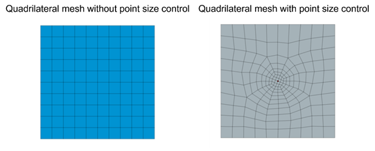
Mesh control is used in FEM software for users to define the nodal location and mesh size. For example, engineers can specify the size of elements surrounding the selected point, as shown in figure 5.
Figure 5. Mesh control using point size control in Midas FEA NX.
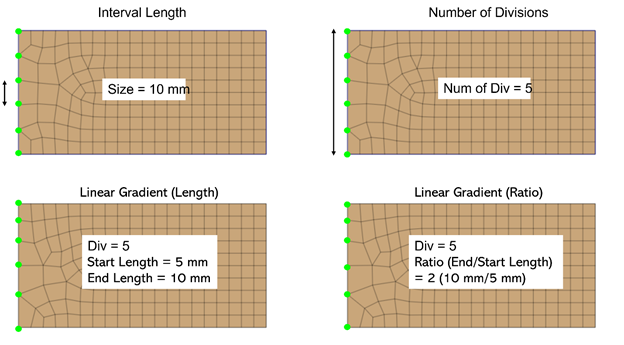
Engineers can also specify the seed size at a particular edge, shown in figure 6. This is particularly helpful at the connection boundary of the mesh bodies with different element sizes.
Figure 6. Mesh control using various edge size control methods in Midas FEA NX.
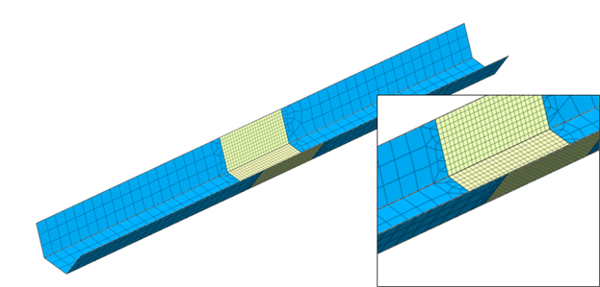
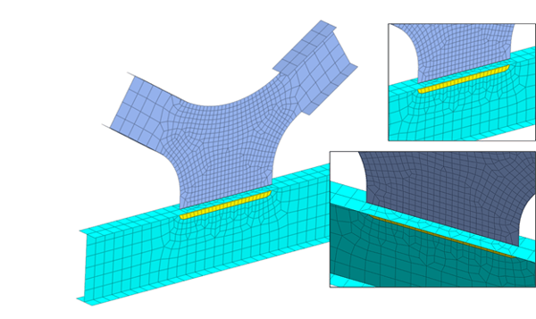
There are also instances where the fine mesh is needed around locations of structural interests. For example, large displacement and stress variation is expected around where the load is applied, or the moment might be high along part of the bridge girder from the general beam element analysis. It is more economical and time-saving to only apply fine mesh around the said regions while representing the rest of the structure using coarse mesh. Edge mesh control can be implemented to connect the coarse mesh to the fine mesh, which implements merged nodes at the mesh set boundaries and a smooth element size transition to prevent distorted elements. Figure 7 and figure 8 show two examples of mesh size transition from coarse to fine mesh while ensuring element quality for better analysis results.
Figure 7. Mesh transition between fine and coarse mesh utilizing edge seeds control on a steel tub girder plate element mesh.
Figure 8. Mesh transition at I girder connection utilizing edge seeds control to ensure merged nodes at mesh sets boundaries.
References:
[1] Cook, Robert D., Malkus, David S., Plesha, Michael E., Witt, Robert J., Concepts and Applications of Finite Element Analysis, Fourth Edition, 2001, John Wiley & Sons Inc., New York, NY.
https://www.midasoft.com/bridge-library/civil/products/midasfeanx
jsun@midasoft.com
Comments

