
-
ascent-p
mimaki jv-3 sp выдает ошибку Y current
Доброй ночи!Специалисты,подскажите пожалуйста,недавно приобрели mimaki jv-3 sp,при печати останавливается и выдает Y current,что это значит,и как это можно устранить?
-
DimaS_
- Старожил

- Сообщения: 1410
- Зарегистрирован: 10 янв 2005 11:02
- Последний визит: 03 июн 2023 19:07
- Изменить репутацию:
Репутация:
Голосов: 49 - Откуда: Россия

Сообщение DimaS_ » 04 дек 2010 07:03
Грязные направляющие. Моем спиртом начисто обе направляющие потом смазываем маслом для швейных машин. Возможно еще что износ втулок и требуется их замена.
-
Inessa
Сообщение Inessa » 17 дек 2010 18:31
пора менять шкив, только сама недавно поменяла (об этой ошибке меня предупреждало — неоднократно), а потом в один прекрасный день при печати машина остановилась и сделала ПИИИИИИИ, выключили её разобрали, а в шкиве полетел подшипник
-
Марченко Илья
Сообщение Марченко Илья » 17 дек 2010 19:27
А быть может проблема в двигателе, не звенит при движении каретки?
-
The_Vadim
- Активный участник
- Сообщения: 336
- Зарегистрирован: 15 дек 2010 20:34
- Последний визит: 03 май 2023 23:31
- Изменить репутацию:
Репутация:
Голосов: 3 - Откуда: ногинск

Сообщение The_Vadim » 17 дек 2010 21:34
была такая проблема, хотя направляющие смазывал регулярно (дико сработанные с канавками от подшипников), прошприцевал подшипники каретки (начальник подсказал) — проблема исчезла. только без фанатизма, а то масло капать будет.
-
Razvantyau
Сообщение Razvantyau » 16 сен 2011 14:59
У меня ночной печатник додумался масла капнуть на большой ремень (как потом он сказал очень уж он туго ходил) На выхлопе я получил замену энкодерной ленты.
-
The_Vadim
- Активный участник
- Сообщения: 336
- Зарегистрирован: 15 дек 2010 20:34
- Последний визит: 03 май 2023 23:31
- Изменить репутацию:
Репутация:
Голосов: 3 - Откуда: ногинск
Сообщение The_Vadim » 16 сен 2011 23:37
Что-то связь не улавливается между лентой и ремнем. А печатник молоток «все верно» подметил
Вернуться в «Принтеры MIMAKI»
Кто сейчас на конференции
Сейчас этот форум просматривают: нет зарегистрированных пользователей и 0 гостей
Answer: Please see following procedures:
If a carriage collides with the media to cause an error, perform the following procedure:
1. Turn off the main power switch on the back side of the main unit.
2. Remove the front cover, and then move the carriage to carefully remove the
media.
3. When the main power switch on the back side of the main unit is in the off
position, move the carriage with your hands to check that it moves smoothly.
4. Move the carriage slowly with your hands to return it to the station
(the right side from the front of the main unit).
5. Install the front cover and turn on the main power switch on the back side of
the main unit. Press the power button on the front side of the main unit, and
then perform cleaning and test drawing after the machine is started.
If the result of test drawing is not acceptable,
see: “Q: “Unusual nozzle test was printed”.
If the error is recurrent, perform the following procedure:
1. Restart the main unit.
2. Check the timing when the error occurs and please contact us.
•Does it occur immediately after turning on the main unit?
•Does it occur during printing?
•Does it occur when printing other data?
-
#1
We had a blackout in our area last night and have since been getting ERROR 404 Y CURRENT on boot on our UJV55-320. Video here
We are not able to find anything blocking the path and connections to the board all seem fine. Really hoping the motor or board aren’t fried. Any ideas for troubleshooting?
I was thinking maybe the «zero position» of the head might be knocked out of place. Anybody know how to recalibrate?
Thanks in advance for any and all suggestions.
Last edited: Oct 1, 2021
-
#2
I’ve never worked on that machine but I have worked on tons of Mimakis and they all have similar designs. I would run an encoder test in the service mode to see if it is working properly. The encoder and the motor are deeply reliant on each other so if one fails, it can affect the other. The fact that the motor moves the carriage at all means it’s getting power and is capable of moving. That’s why I would suspect the encoder first as it would fail once it tries to move and measure the media.
-
#3
Looks like the error happens when the motor tries to move the carriage at higher speeds and power levels. This normally would indicate a failing Y motor, especially If this machine gets heavy use. Was the motor getting louder leading up to this?
-
#4
I’ve never worked on that machine but I have worked on tons of Mimakis and they all have similar designs. I would run an encoder test in the service mode to see if it is working properly. The encoder and the motor are deeply reliant on each other so if one fails, it can affect the other. The fact that the motor moves the carriage at all means it’s getting power and is capable of moving. That’s why I would suspect the encoder first as it would fail once it tries to move and measure the media.
Thanks for the suggestion. I was able to get in to the service menu but can’t seem to find the encoder test. Do you know where that is located within the menu?
-
#5
Looks like the error happens when the motor tries to move the carriage at higher speeds and power levels. This normally would indicate a failing Y motor, especially If this machine gets heavy use. Was the motor getting louder leading up to this?
Yes, the machine gets heavy use…about 12 hours a day nonstop. I am not in the large format press room consistently but the operators say they did not notice any more noise from the motors.
-
#6
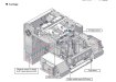
Error 404 during the boot usually caused by the faulty start point sensor, it interrupter or bad communication with it. Try to determine what is happening before error. Most likely you’ll see the carriage moving to the right after the station moves down until the carriage reached right edge and gives you an error. It might try do it few times moving left and right before it stops with an error. Usually it is a shifted or bended metal plate which must interrupt starting point optical sensor and stop the carriage. To find the sensor you have to remove carriage cover and find it inside somewhere behind the heads at top right before the circuit boards (HDC). Try to see what is happening with the sensor before it stops. Ill attach the picture with the sensor position. I really doubt that the problem is in Y motor, you easily can detect faulty in most cases when it becomes noisy, worsening print quality in bi-directional mode or random 404 errors during the printing, but not at the initialization
-

Image 10-1-21 at 1.30 PM.jpg
93.8 KB
· Views: 372
Last edited: Oct 1, 2021
-
#7
You can test Y origin sensor from the service menu. Go to Test>Sensors>Y origin sensor
-
#8
This is a relatively new printer, are you not under warranty? Update your firmware. Check the carriage in the off state wether it moves smoothly in the Y direction. Apply grease to the LM guide. Check CN14 & 15 on the main PCB and the motor cable. (Had an issue with my first install of a UJV 55 where the cable was not connected in the leg of the stand causing all kinds of take-up issues.) Lastly, replace the Y-Axis motor.
-
#9
Mimaki discontinued those printers years ago. It was replaced by UCJV and UV
-
#10
After a few days of troubleshooting we narrowed it down to the motor and got it replaced. Our dealer charged us $1500 just for the Y motor which seems exorbitant. Unfortunately we did not have time to source it ourselves.
After replacing the motor, we are realizing that the rail bearings and encoder will likely need to be replaced soon as well. Mimaki only sells the rail bearings as a set of 4 with the 2 rails which I have been told is in the thousands.
I plan on contacting Motion Industries to see if they can supply the bearings but do not have the exact specs nor a spare part to take. Does anyone know the part # or correct specs? Any references for 3rd party parts would be much appreciate as well
-
#11
Sure, they’re using Hiwin MGN15H carriage in all their products. You don’t have to find the exact one, just be sure it is the same dimensions and the screws are in same place, there is too different carriages of type you need: with or without separator, the carriages without ball separator is more noisy but cheaper. You can remove on of them from the rail to be completely sure you buying needed one. But I really doubt you’ll need any, those are very reliable and if you don’t hear any screeching sounds when printer carriage is moving there is no need to replace them. And honestly error 404 during the start seems doubtful for me, technically this error appears when logic detects unexpected overcurrent to the motor which usually means the motor couldn’t move the carriage using common power and has to consume more energy than before, and it might be while it printing, but not at the start. And they using the same motors in their SWJ, SIJ and UV55 models, maybe in JFX too but I could be wrong, and when those printers has 404 error it is very rare that Y motor caused it. But anyway you should replace the motor at least every 5 years, to prevent possible problems which dead motor could cause, so it wasn’t unnecessary
Last edited: Oct 5, 2021
-
#12
Sure, they’re using Hiwin MGN15H carriage in all their products. You don’t have to find the exact one, just be sure it is the same dimensions and the screws are in same place, there is too different carriages of type you need: with or without separator, the carriages without ball separator is more noisy but cheaper. You can remove on of them from the rail to be completely sure you buying needed one. But I really doubt you’ll need any, those are very reliable and if you don’t hear any screeching sounds when printer carriage is moving there is no need to replace them. And honestly error 404 during the start seems doubtful for me, technically this error appears when logic detects unexpected overcurrent to the motor which usually means the motor couldn’t move the carriage using common power and has to consume more energy than before, and it might be while it printing, but not at the start. And they using the same motors in their SWJ, SIJ and UV55 models, maybe in JFX too but I could be wrong, and when those printers has 404 error it is very rare that Y motor caused it. But anyway you should replace the motor at least every 5 years, to prevent possible problems which dead motor could cause, so it wasn’t unnecessary
I appreciate all the info. I did think it was odd that a black out would damage the motor. You would think the board components would be the first thing to go. I am holding on to the motor to test and repair if it is actually damaged.
We tried oiling the bearings as best as we could. It did help quite a bit but according to the technician, the head should easily glide across the rail. Ours definitely requires some pressure to move it. Any suggestions on how to clean or lubricate the bearings before we attempt a replacement?
-
#13
The system only way I know to lubricate those carriages you can find in this document
But you can use syringe to push the lube inside the carriage, and to do it you will need to unscrew the bearing from the back of printer’s carriage to release it back then move it outside of printer’s carriage then remove the screw on the side of the bearing, you’ll see it in the document, and push lubricant inside
-
#14
Update:
The fun continues…
Printer started throwing a System Halt (2): 509 error. We opened up the head and cleaned the encoder sensor the best we could. The error seems to have subsided but now there is obviously something very wrong with the way the encoder is functioning…We output a test print and each pass gets further and further off the correct Y position.
Ran an encoder test and got the attached results…
-

1.png
629.6 KB
· Views: 330
-

-

3.png
1.4 MB
· Views: 335


-
#15
Check the position of the encoders sensor, and it still might be the motor issue as it has its own encoder
-
#16
Isaac_K, did you solve the problem?
-
#17
Isaac_K, did you solve the problem?
Not quite yet. We took your advice and were able to start printing correctly by reseating the encoder sensor…temporarily. However, we are still getting that System Halt error intermittently. We have called in the techs at this point and have received a quote on a new encoder and sensor.
Thanks for your suggestions. It helped us get to the point where we can output at least our rush jobs.
-
#18
This error means that the HDC board received a different amount of scales from the sensor.
Not as expected. It might be still the motor. Did you try your old motor
-
#19
This error means that the HDC board received a different amount of scales from the sensor.
Not as expected. It might be still the motor. Did you try your old motor
Potentially dumb question but I am unfamiliar with digital equipment (I mainly deal with offset).
Are scales the different sections going across the encoder strip? If so, could oil on the strip cause an issue with the sensor correctly reading each scale?
The last tech that was out here put oil all along the rail and I thought that was odd. Over a couple days of printing on and off, oil worked it’s way on to the encoder strip and I am sure into other unknown areas.
I was going to try the original motor again but have not had a chance. Will update once I do.
-
#20
No, the scales are the same for the entire length. Oil on a scale will affect the readings, it usually happens with new machines, there might be few oil drops from the rail. Just wipe the stripe with alcohol, do not use any solvent!
Did you noticed in what part of the printing table error usually appears?
-
#2
Might be a dumb solution. I had this issue before and took us a while to figure out but we sat the printer too far back and was touching the wall. Try to see if there is anything in the way of the printer that may stop it from moving fully back or forward.
-
#4
Could you please answer me for these two questions. First In mimaki printer there are two fuses in power board… Do you know where is the place and what shapes of another fuse in another boards maybe
Secondly :what is the main task of cap top of printhead and when we have to change it (not cap station)
Tarek.hammoud78@gmail.com
Проблема с Mimaki UJF-3042 MK2
- Цитата
Сообщение Agaress » 22 авг 2018 21:54
Все доброго времени суток! проблема такова, машина новая полностью, через неделю стала появляться ошибка двигателя вайпера (403) позже она пропала и начала выпадать «current y», по сервиснику это остаточное напряжение на двигателе по оси y, напряжение везде промеряли, стоит бесперебойник, на днях поменяли блок питания, но по прошествии суток опять все повторилось. С чем может быть связано, может кто сталкивался?
MAINTENANCE MANUAL > Troubleshooting > Details on Errors and Malfunctions > List of Error Messages
Model SWJ-320S Issued 2012.07.19 Revised 2013.03.08 F/W ver
7.1.2 List of Error Messages
List of Error Messages ?3/5?
No.
LCD
ERROR 19d
HDC V36 [12__]
29
ERROR 1a1
INK SUP PMP [12__]
30
ERROR 201
31
COMMAND
ERROR 202
PARAMETER
32
ERROR 304
33
USB INIT ERR
ERROR 305
USB TIME OUT
34
ERROR 401
35
MOTOR X
ERROR 403
X CURRENT
36
ERROR 402
37
MOTOR Y
ERROR 404
Y CURRENT
38
© 2013 MIMAKI ENGINEERING CO.,LTD.
Cause
Control error to HDC PCB voltage
Voltage of the HDC PCB that displayed
number on the LCD is lower than pre-
scribed voltage.
Voltage of the ink supply pump can not be
set it to the prescribed voltage.
Command error
Other data than commands is received
Parameter error
Parameter out of the numeral value range
is received
USB initialization error
(Failures in initializing USB device)
USB time-out
(Occurrence of time-out error on USB
device)
X Servo error
(Excessive load to the X-motor)
X-motor current
(Over current error of X-motor is detected.)
Y Servo error
(Excessive load to the Y-motor)
Y-motor current
(Over current error of Y-motor is detected.)
Remark
1.0
List of Countermeasures
1. Check the output pressure of the DC power supply (36V)
and the DC power supply (5V).
2. Replace the HDC PCB with a new one.
3. Replace the power supply above.
4. Replace the MAIN PCB with a new one.
1. Check if there is no parameter error?
2. Check the output pressure of the DC power supply (36V)
and the DC power supply (5V).
3. Replace the power supply above.
4. Replace the CIO PCB with a new one.
5. Replace the MAIN PCB with a new one.
1. Check if the output set of the PC matches the set of the
machine side?
2. Change the profile.
3. Check if there is no parameter error?
4. Check if there is no trouble on the USB Cable?
5. Replace the USB Cable.
6. Replace the MAIN PCB with a new one.
1. Check if there is no parameter error?
2. Replace the USB Cable.
3. Replace the MAIN PCB with a new one.
1. Check if there is no error on the print data.
(Check if the same error occurs on other data?)
2. Check if there is no trouble on the Timing Belt.
3. Check if there is no trouble on the Motor Cable.
(disconnecting, burnout, or the like)
4. Check the FFC between each PCB and Short-connectors
connected on the PCB.
5. Replace the X-axis Motor with a new
1. Check if there is no error on the print data.
(Check if the same error occurs on other data?)
2. Check if it moves to the Y-direction smoothly in the power-
off condition.
3. Check if there is no trouble on the Timing Belt.
4. Check if there is no trouble on the Motor Cable.
(disconnecting, burnout, or the like)
5. Check the FFC between each PCB and Short-connectors
connected on the PCB.
6. Replace the Y-axis motor with a new one.
Rev.
1.2
1
(Refer to 3.3.1)
2
(Refer to 3.3.1)
3
(Refer to 3.3.1)
4
(Refer to 3.3.1)
5
one.(Refer to 3.3.1)
6
7
(Refer to 6.3.2)
8
7.1.2
R.1.2
P.3
- Dealing with Problems
- Problems Indicated by Messages
- Error Messages
- Problems Indicated by Messages
Check the error details in the following table corresponding to the error numbers displayed:
If the problem persists even after carrying out the corrective action corresponding to the error number, contact your local distributor, our sales office, or service center. .
|
Error number/Message |
Cause |
Corrective action |
|---|---|---|
|
401 MOTOR X |
|
Check the following points:
|
|
402 MOTOR Y |
|
|
|
403 X Current |
|
|
|
404 Y Current |
|
|
|
41b ** NO MEDIA ** |
|
|
|
50a Y ORIGIN |
|
|
|
50b FRONT EDGE |
|
|
|
50c WIDTH |
|
|
|
520 REAR EDGE |
|
|
|
901 OPERATION |
|
|
|
902 DAT REMAIN |
|
|
|
C02 MAIN RAM |
|
|
|
C04 EEPROM |
|
|
|
C06 BUFFER |
|
|
|
C08 POWER |
|
|
|
C10 Commands |
|
Check the following points:
|
|
C11 PARAMETER |
|
|
|
C12 DEVICE |
|
|
|
C13 PM OVER |
|
|
|
C15 AUTO FEED |
|
|
|
|
|
|
C16 AUTO I/F |
|
|
|
C20 I/O |
|
|
|
C27 BUFFERover |
|
|
|
C31 NO DATA |
|
|
|
C32 DATAtooBIG |
|
|
|
C33 SHEET SIZE |
|
|
|
C36 MARK DETECT |
|
Check the following points:
|
|
C37 MARK ORG |
|
|
|
C38 MARK SCALE |
|
|
|
|
|
|
|
|
|
|
|
|
|
|
|
|
|
|
C39 MARK ID |
|
Check the following points:
|
|
C51 PINCH POS* |
|
|
|
C60 PenEncoder |
|
|
|
C61 Pen Stroke |
|
Check the following points:
|
You are here: Home / error code / Mimaki JFX200-2513 Error Codes and quick guides [Solved]
Fixing Mimaki JFX200-2513 Error Codes list
– Compatible Printer model: Mimaki JFX200-2513
– Mimaki JFX200-2513 Error Code description:
- Code: 000
- Display: SYSTEM HALT (*) 000 : UNNOWN ERR
- Description: Unnown error
- Troubleshooting Guides: 1.Update F/W. 2. Check and clear the parameter. 3. Replace the main PCB with a new one.
- Code: 04
- Display: ERROR 04 PARAM ROM
- Description: Access Error of the PARAMETER ROM 1.The state that cannot access “FROM” on the MAIN PCB. 2.The state that cannot access “EEPROM” on the Central-IO PCB.
- Troubleshooting Guides: 1. Replace the FFC and cable located between the HDC PCB and the MAIN PCB. 2. Replace the FFC and cable located between the HDC PCB and the MAIN PCB. 3. Replace the Central-IO PCB with a new one. 4. Replace the MAIN PCB with a new one.
- Code: 104
- Display: SYSTEM HALT (*) 104 : +35V RECVR
- Description: 35 V Power recovery error
- Troubleshooting Guides: 1. Replace the DC power supply (36V) PCB with a new one. 2. Replace the main PCB with a new one.
- Code: 108
- Display: ERROR 108 HD CONNECT[12345678]
- Description: Head connection error (Head connection can not be confirmed)
- Troubleshooting Guides: 1. Check connection between the HDC PCB from the Print Head 2. Replace the HDC PCB with a new one. 3 3.Replace the print head with a new one.
- Code: 10e
- Display: SYSTEM HALT (*) 10e :FROM CLEAR
- Description: F-ROM CLEAR error (F-ROM clear unable) F-ROM is not clearable on parameter writing, FW down loading and log clearing. (fls_secclr)
- Troubleshooting Guides: 1. Execute the memory check (F-ROM) of [#TEST]. 2. Upload the parameter and initialize all parameters with [#PARAMETER]. 3. Replace the main PCB with a new one.
- Code: 10f
- Display: SYSTEM HALT (*) 10f : FROM WRITE
- Description: FROM WRITE error (F-ROM writing unable) F-ROM is not clearable on parameter writing, FW down loading and log clearing. (fls_secclr)
- Troubleshooting Guides: 1. Execute the memory check (F-ROM) of [#TEST]. 2. Upload the parameter and initialize all parameters with [#PARAMETER]. 3. Replace the main PCB with a new one.

- Code: 110
- Display: SYSTEM HALT (*) 110 : PCB KEY
- Description: No keyboard PCB
- Troubleshooting Guides: 1. Check the connections between the keyboard PCB and the main PCB and then disconnect and connect the FFCs. 2. Replace the FFCs of the above routes. 3. Replace the keyboard PCB with a new one. 4. Replace the main PCB with a new one.
- Code: 115
- Display: SYSTEM HALT (*) 115 : PCB MAIN-F1
- Description: The F1 fuse on the MAIN PCB went out.
- Troubleshooting Guides: 1. Replace the MAIN PCB with a new one.
- Code: 116
- Display: SYSTEM HALT (*) 116 : PCB MAIN-F2
- Description: The F2 fuse on the MAIN PCB went out.
- Troubleshooting Guides: 1. Replace the MAIN PCB with a new one.
- Code: 117
- Display: SYSTEM HALT (*) 117 : PCB MAIN-F3
- Description: The F3 fuse on the MAIN PCB went out.
- Troubleshooting Guides: 1. Replace the MAIN PCB with a new one.
- Code: 11E
- Display: SYSTEM HALT (*) 11E : PCB SLRY
- Description: No slider relay PCB
- Troubleshooting Guides: 1.Check the connections between the main PCB and the slider relay PCB and then disconnect and connect the FFC. 2. Replace the FFC of the above routes. 3. Replace the slider relay PCB with a new one. 4. Replace the main PCB with a new one.
- Code: 11f
- Display: SYSTEM HALT (*) 11f : PCB SLIDER
- Description: No slider PCB.
- Troubleshooting Guides:
– Mimaki JFX200-2513 Error codes and solution steps to solve problems:
- Code: 120
- Display: SYSTEM HALT (*) 120 : LCD THERM.
- Description: LCD thermistor IC RW error
- Troubleshooting Guides: 1. Check the connections between the keyboard PCB and the main PCB, and then disconnect and connect the FFCs. 2. Replace the FFCs and the cables of the above routes. 3. Replace the keyboard PCB with a new one. 4. Replace the main PCB with a new one. 5. Replace the DC power supply (5V) with a new one.
- Code: 122
- Display: SYSTEM HALT (*) 122 : PRAM NONE
- Description: No PRAM
- Troubleshooting Guides: 1. Update F/W. 2. Replace the PRAM PCB with a new one. 3.Replace the main PCB with a new one.
- Code: 122
- Display: ERROR 122 CHECK:SDRAM
- Description: PRAM size is not sufficient at FW upgrading (fw_updmsg). 1. Update F/W. 2. Replace the main PCB with a new one. 3. Replace the PRAM PCB with a new one.
- Troubleshooting Guides: 1. Update F/W. 2. Replace the main PCB with a new one. 3. Replace the PRAM PCB with a new one.
- Code: 123
- Display: SYSTEM HALT (*) 123 : PRAM DATA
- Description: PRAM data error
- Troubleshooting Guides: 1. Update F/W. 2. Replace the PRAM PCB with a new one. 3.Replace the main PCB with a new one.
- Code: 124
- Display: SYSTEM HALT (*) 124 : PRAM ADDR
- Description: PRAM address error
- Troubleshooting Guides: 1. Update F/W. 2. Replace the PRAM PCB with a new one. 3.Replace the main PCB with a new one.
- Code: 125
- Display: SYSTEM HALT (*) 125 : EEPROM READ
- Description: EEPROM read trouble CIO Register (EER:Address 74) bit6
- Troubleshooting Guides: 1. Update F/W. 2. Upload the parameter and initialize parameter with #PARAMETER. 3. Check the connection state between main PCB – central-IO PCB. 4. Replace the main PCB with a new one. 5. Replace the central-IO PCB with a new one.
- Code: 126
- Display: SYSTEM HALT (*) 126 : EEPROM WR
- Description: EEPROM write trouble CIO Register (EER:Address 74) bit7
- Troubleshooting Guides: 1. Update F/W. 2. Upload the parameter and initialize parameter with #PARAMETER. 3. Check the connection state between main PCB – central-IO PCB. 4. Replace the main PCB with a new one. 5. Replace the central-IO PCB with a new one.
- Code: 127
- Display: SYSTEM HALT (*) 127 : POWER OFF
- Description: Power OFF detection error (Not to OFF) Power OFF process is conducted in the Power ON/OFF control without pushing down the sub-power SW.
- Troubleshooting Guides: 1. Check the connection state between sub-power SW and keyboard PCB. 2. Check the connections between the keyboard PCB and the main PCB, and then disconnect and connect the FFCs. 3. Check the connector connection of DC power supply (36V). 4. Check if there is no error on the power path from the AC inlet. 5. Replace the DC power supply (36V) with a new one. 6. Replace the keyboard PCB with a new one. 7. Replace the main PCB with a new one.
- Code: 128
- Display: ERROR 128 HDC FIFO OVER
- Description: HDC FIFO OVER error (Data transmission speed is too fast control PCB trouble) HDC FIFO OVERRUN is detected at the scan slider process (ScanSlider)
- Troubleshooting Guides: 1. Check the parameter. (Is the scan parameter the default value?) 2. Update F/W. 3. Check if there is no data error from RIP. 4. To make sure, repeat RIP. 5. Disconnect and connect the FFC located between the Main PCB and the HDC PCB. 6. Replace the FFC and cable located between the main PCB and the HDC PCB. 7. Replace the HDC PCB with a new one. 8. Replace the main PCB with a new one.
- Code: 128
- Display: ERROR 128 HDC FIFO UNDER
- Description: HDC FIFO UNDER error (Data transmission speed is too slow control PCB trouble) HDC FIFO UNDERRUN is detected at the scan slider process (ScanSlider)
- Troubleshooting Guides: 1. Check the parameter. (Is the scan parameter the default value?) 2. Update F/W. 3. Check if there is no data error from RIP. 4. To make sure, repeat RIP. 5. Disconnect and connect the FFC located between the Main PCB and the HDC PCB. 6. Replace the FFC and cable located between the main PCB and the HDC PCB. 7. Replace the HDC PCB with a new one. 8. Replace the main PCB with a new one.
- Code: 129
- Display: ERROR 129 BATTERY EXCHANGE
- Description: Battery dead (RTC battery dead is detected.) Proper information of printer or time (Dedicated IC) unusable on printer initializing process (opinit).
- Troubleshooting Guides: 1. Replace a battery equipped on the main PCB with new one. (CR2032) * The new battery should be the same product or the equivalent. * Discard the old battery according to the instruction from the maker.
- Code: 12a
- Display: ERROR 12a HDC SPEED
- Description: Ink discharging trigger error As intervals of ink discharging trigger are too short, next discharging trigger occurs before one wave shape is completed.
- Troubleshooting Guides: 1. Perform the linear encoder test. 2. Replace the linear scale. 3. Replace the linear encoder sensor. 4. Replace the HDC PCB with a new one. 5. Replace the MAIN PCB with a new one.
- Code: 12e
- Display: ERROR 12e Head Faild[xxxx]
- Description: Abnormality of the print head. Abnormality of the driver of the print head. COM overcurrent (HDC STAT4 bit2) (We did not see the current status.)
- Troubleshooting Guides: 1. Update F/W. 2. Initialize a parameter. 3. Replace the print head with a new one. 4. Replace the HDC PCB with a new one.
- Code: 130
- Display: ERROR 130 HD DATA SEQ
- Description: Head data transferring sequence error
- Troubleshooting Guides: 1. Disconnect and connect the FFC located between the HDC PCB and the main PCB. 2. Replace the FFC located between the HDC PCB and the main PCB. 3. Replace the HDC PCB with a new one. 4. Replace the main PCB with a new one.
- Code: 146
- Display: ERROR 146 E-LOG SEQ
- Description: Sequential number abnormality of the event log
- Troubleshooting Guides: 1. Initialize a event log. 2. Replace the main PCB with a new one.
- Code: 147
- Display: SYSTEM HALT (*) 147 : DS-IC BUSY
- Description: DALLAS IC BUSY error
- Troubleshooting Guides: 1. Check connection of the ID contact PCB connection cable and damage of the cable. 2. Try to use a different bottle. 3. Replace the ID contact PCB assy. with a new one. 4. Replace the INK SYSYTEM PCB with a new one.
- Code: 151
- Display: ERROR 151 MAIN PCB V1R2
- Description: Main board 1.2V power supply is abnormal.
- Troubleshooting Guides: 1. Check the output pressure of the DC power supply (36V) and the DC power supply (5V). 2. Replace the power supply above. 3.Replace the main PCB with a new one.
- Code: 152
- Display: ERROR 152 MAIN PCB V2R5
- Description: Main board 2.5V power supply is abnormal.
- Troubleshooting Guides: 1. Check the output pressure of the DC power supply (36V) and the DC power supply (5V). 2. Replace the power supply above. 3.Replace the main PCB with a new one.
- Code: 153
- Display: ERROR 153 MAIN PCB V3R3
- Description: Main board 3.3V power supply is abnormal.
- Troubleshooting Guides: 1. Check the output pressure of the DC power supply (36V) and the DC power supply (5V). 2. Replace the power supply above. 3.Replace the main PCB with a new one.
- Code: 154
- Display: ERROR 154 MAIN PCB V05
- Description: Main board 5V power supply is abnormal.
- Troubleshooting Guides: 1. Check the output pressure of the DC power supply (36V) and the DC power supply (5V). 2. Replace the power supply above. 3.Replace the main PCB with a new one.
- Code: 155
- Display: ERROR 155 MAIN PCB V36-1
- Description: Main board 36-1V power supply is abnormal.
- Troubleshooting Guides: 1. Check the output pressure of the DC power supply (36V) and the DC power supply (5V). 2. Replace the power supply above. 3.Replace the main PCB with a new one.
- Code: 156
- Display: ERROR 156 MAIN PCB V5B
- Description: Main board 5VB power supply is abnormal.
- Troubleshooting Guides: 1. Check the output pressure of the DC power supply (36V) and the DC power supply (5V). 2. Replace the power supply above. 3.Replace the main PCB with a new one.
- Code: 157
- Display: ERROR 157 MAIN PCB VTT
- Description: Main board VTT power supply is abnormal.
- Troubleshooting Guides: 1. Check the output pressure of the DC power supply (36V) and the DC power supply (5V). 2. Replace the power supply above. 3.Replace the main PCB with a new one.
- Code: 158
- Display: ERROR 158 MAIN PCB V36-2
- Description: Main board 36-2V power supply is abnormal.
- Troubleshooting Guides: 1. Check the output pressure of the DC power supply (36V) and the DC power supply (5V). 2. Replace the power supply above. 3.Replace the main PCB with a new one.
- Code: 15d
- Display: SYSTEM HALT (*) 15d : MAIN FPC-1
- Description: 30pinFPC 1 of main PCB connect error
- Troubleshooting Guides: 1. Check the connections between the HDC PCB and the main PCB, and then disconnect and connect the FFCs. 2. Replace the FFCs of the above routes. 3. Replace the HDC PCB with a new one. 4. Replace the main PCB with a new one.
- Code: 15f
- Display: ERROR 15f HEAD DRIVE HOT
- Description: COM driver becomes the high temperature.
- Troubleshooting Guides: 1. Check the operation of the HDC PCB cooling fan. 2. Disconnect and connect the FFC located between the HDC PCB and the main PCB. 3. Replace the HDC PCB with a new one. 4. Replace the print head with a new one.
- Code: 160
- Display: SYSTEM HALT (*) 160 : PCB MAIN-F5
- Description: MAIN PCB fuse (F5) disconnected. PDC IPORT Register bit20: ON
- Troubleshooting Guides: Replace the main PCB with a new one. Before main PCB replace, do the following checks. 1. Check the connections between the central-IO PCB and the main PCB, and then disconnect and connect the FFC and cable. 2. Check short between 1 pin and 4 pin of CN1 of the central-IO PCB. (If shorted out, replace also the central-IO PCB.)
- Code: 161
- Display: SYSTEM HALT (*) 161 : PCB MAIN-F6
- Description: MAIN PCB fuse (F6) disconnected. PDC IPORT Register bit21: ON
- Troubleshooting Guides: Replace the main PCB with a new one. Before main PCB replace, do the following checks. 1. Check the connections between the central-IO PCB and the main PCB, and then disconnect and connect the FFC and cable. 2. Check short between 1 pin and 4 pin of CN1 of the central-IO PCB. (If shorted out, replace also the central-IO PCB.)
- Code: 16e
- Display: ERROR 16e MAIN PCB V3R3B
- Description: Main board 3.3VB power supply is abnormal.
- Troubleshooting Guides: 1. Check the output pressure of the DC power supply (36V) and the DC power supply (5V). 2. Replace the power supply above. 3.Replace the main PCB with a new one.
- Code: 171
- Display: ERROR 171 NEW HEAD CONNECT
- Description: New print head was recognized. Compare S/N written in the head memory with S/N stored in the machine.
- Troubleshooting Guides: It is normal that an error occurs only at the time of the first start after having connected a new head. It is abnormal that an error occurs at the time of start every time. 1. Check connection between the HDC PCB from the print head 2. Replace the HDC PCB with a new one. 3. Replace the print head with a new one
- Code: 172
- Display: ERROR 172 MAIN PCB Q6 Check
- Description: The main PCB Q6 is disabled (short mode). (Displayed only at startup in the maintenance open mode or other than SUPPORT=0.)
- Troubleshooting Guides: 1. Replace the main PCB with a new one.
- Code: 17e
- Display: SYSTEM HALT (*) 17e : PCB IIO1
- Description: No INK-IO1 PCB An error occurred at serial communication check after configuration.
- Troubleshooting Guides: 1. Check the connections between the INK SYSTEM PCB and the central-IO PCB and then disconnect and connect the FFC. 2. Replace the FFC of the above routes. 3. Replace the INK SYSTEM PCB with a new one. 4. Replace the central-IO PCB with a new one.
- Code: 181
- Display: SYSTEM HALT (*) 181 : PCB H21
- Description: No HDC1 PCB An error occurred at serial communication check after configuration.
- Troubleshooting Guides: 1. Check the connections between the HDC PCB and the main PCB and then disconnect and connect the FFC. 2. Replace the FFC and cable of the above routes. 3. Replace the HDC PCB with a new one. 4. Replace the main PCB with a new one.
- Code: 185
- Display: SYSTEM HALT (*) 185 : PCB LED
- Description: No INK LED PCB
- Troubleshooting Guides: 1. Check the connections between the INK LED PCB and the INK SYSTEM PCB and then disconnect and connect the FFC. 2. Replace the FFC of the above routes. 3. Replace the INK LED PCB with a new one. 4. Replace the INK SYSTEM PCB with a new one.
- Code: 186
- Display: ERROR 186 HDC OVERFLOW
- Description: Wave shape overflow Wave shape data is abnormal.
- Troubleshooting Guides: 1. Pull out/ insert cable between HDC PCB and MAIN PCB. (FFC changes PCB, Optical conversion PCB) 2. Replace the HDC PCB with a new one. 3. Replace the Optical conversion PCB with a new one. 4. Replace the FFC changes PCB with a new one. 5. Replace cable between HDC PCB and MAIN PCB. 6. Replace the MAIN PCB with a new one.
- Code: 187
- Display: ERROR 187 HDC SLEW RATE
- Description: Wave shape slew rate error Wave shape data is abnormal.
- Troubleshooting Guides: 1. Pull out/ insert cable between HDC PCB and MAIN PCB. (FFC changes PCB, Optical conversion PCB) 2. Replace the HDC PCB with a new one. 3. Replace the Optical conversion PCB with a new one. 4. Replace the FFC changes PCB with a new one. 5. Replace cable between HDC PCB and MAIN PCB. 6. Replace the MAIN PCB with a new one.
- Code: 188
- Display: ERROR 188 HDC MEMORY
- Description: Wave shape memory error At wave shape memory writing, it cannot be written due to address conflict.
- Troubleshooting Guides: 1. Pull out/ insert cable between HDC PCB and MAIN PCB. (FFC changes PCB, Optical conversion PCB) 2. Replace the HDC PCB with a new one. 3. Replace the Optical conversion PCB with a new one. 4. Replace the FFC changes PCB with a new one. 5. Replace cable between HDC PCB and MAIN PCB. 6. Replace the MAIN PCB with a new one.
- Code: 18a
- Display: ERROR 18a MAIN PCB V_CORE
- Description: Main board V_CORE power supply is abnormal.
- Troubleshooting Guides:
- Code: 18b
- Display: ERROR 18b MAIN PCB V3R3B
- Description: Main board 1.5V power supply is abnormal.
- Troubleshooting Guides:
- Code: 18c
- Display: ERROR 18c MAIN PCB V12
- Description: Main board 12V power supply is abnormal.
- Troubleshooting Guides:
- Code: 18e
- Display: ERROR 18e FLS NOT COMP [12__]
- Description: Flashing control error Flashing for the head which is connected the HDC PCB that displayed number on the LCD can not be completed.
- Troubleshooting Guides: 1. Pull out/ insert cable between HDC PCB and MAIN PCB. (FFC changes PCB, Optical conversion PCB) 2. Replace the HDC PCB with a new one. 3. Replace the Optical conversion PCB with a new one. 4. Replace the FFC changes PCB with a new one. 5. Replace cable between HDC PCB and MAIN PCB. 6. Check connection between the HDC PCB from the Print Head 7. Replace the MAIN PCB with a new one. 8. Replace the Print Head which is connected HDC PCB that displays error with a new one
- Code: 18f
- Display: ERROR 18f OFFSET START [12__]
- Description: Control error to Head voltage Offset of the HDC PCB that displayed number on the LCD can not be started.
- Troubleshooting Guides: 1. Pull out/ insert cable between HDC PCB and MAIN PCB. (FFC changes PCB, Optical conversion PCB) 2. Replace the HDC PCB with a new one. 3. Replace the Optical conversion PCB with a new one. 4. Replace the FFC changes PCB with a new one. 5. Replace cable between HDC PCB and MAIN PCB. 6. Check connection between the HDC PCB from the Print Head 7. Replace the MAIN PCB with a new one. 8. Replace the Print Head which is connected HDC PCB that displays error with a new one
- Code: 18f
- Display: ERROR 18f OFFSET END [12__]
- Description: Control error to Head voltage Offset of the HDC PCB that displayed number on the LCD can not be ended.
- Troubleshooting Guides: 1. Pull out/ insert cable between HDC PCB and MAIN PCB. (FFC changes PCB, Optical conversion PCB) 2. Replace the HDC PCB with a new one. 3. Replace the Optical conversion PCB with a new one. 4. Replace the FFC changes PCB with a new one. 5. Replace cable between HDC PCB and MAIN PCB. 6. Check connection between the HDC PCB from the Print Head 7. Replace the MAIN PCB with a new one. 8. Replace the Print Head which is connected HDC PCB that displays error with a new one
- Code: 19d
- Display: ERROR 19d HDC V36 [12__]
- Description: Control error to HDC PCB voltage Voltage of the HDC PCB that displayed number on the LCD is lower than prescribed voltage.
- Troubleshooting Guides: 1. Check the output pressure of the DC power supply (36V) and the DC power supply (5V). 2. Replace the HDC PCB with a new one. 3. Replace the power supply above. 4. Replace the MAIN PCB with a new one.
- Code: 19F
- Display: ERROR 19F LED 0**0**
- Description: LED UV CURING PCB is disconnect. **Fsub code 1*GCuring unit1 (left) is disconnect to the LED PCB. 2*GCuring unit2 (right) is disconnect to the LED PCB. *=1-8:LED PCB A-H
- Troubleshooting Guides: 1. Check connection of the PCB. 2. Replace the LED PCB. 3. Replace the UVLED Drive PCB.
- Code: 201
- Display: ERROR 201 COMMAND
- Description: Command error Other data than commands is received
- Troubleshooting Guides: 1. Check if the output set of the PC matches the set of the machine side? 2. Change the profile. 3. Check if there is no parameter error? 4. Check if there is no trouble on the USB cable? 5. Replace the USB Cable. 6. Replace the main PCB with a new one.
- Code: 202
- Display: ERROR 202 PARAMETER
- Description: Parameter error Parameter out of the numeral value range is received
- Troubleshooting Guides: 1. Check if the output set of the PC matches the set of the machine side? 2. Change the profile. 3. Check if there is no parameter error? 4. Check if there is no trouble on the USB cable? 5. Replace the USB Cable. 6. Replace the main PCB with a new one.
- Code: 203
- Display: ERROR 203 Ment Command
- Description: Maintenance command Operation of a maintenance command fails *Non-disclosed command Parameter Up/Download and time setting (LcAeMent [M0xfe])
- Troubleshooting Guides: 1. Check the PRM file. 2. Check the number of each parameter. (if PRM matches up to the machine.)
- Code: 303
- Display: SYSTEM HALT (*) 303 : PCB MAIN ET
- Description: Main PCB ethernet IC trouble
- Troubleshooting Guides: 1. Replace the main PCB with a new one.
- Code: 304
- Display: ERROR 304 USB INIT ERR
- Description: USB initialization error (Failures in initializing USB device)
- Troubleshooting Guides: 1. Check if there is no parameter error? 2. Replace the USB Cable. 3. Replace the main PCB with a new one.
- Code: 305
- Display: ERROR 305 USB TIME OUT
- Description: USB time-out (Occurrence of time-out error on USB device)
- Troubleshooting Guides: 1. Check if there is no parameter error? 2. Replace the USB Cable. 3. Replace the main PCB with a new one.
- Code: 401
- Display: ERROR 401 MOTOR X
- Description: X Servo error (Excessive load to the X-motor)
- Troubleshooting Guides: 1. Check if there is no error on the print data. (Check if the same error occurs on other data?) 2. Check if there is no trouble on the timing belt. 3. Check if there is no trouble on the motor cable. (disconnecting, burnout, or the like) 4. Check the FFC between each PCB and shortconnectors connected on the PCB. 5. Replace the X-axis motor with a new one.
- Code: 402
- Display: ERROR 402 MOTOR Y
- Description: Y-servo error (Excessive load to the Y-motor)
- Troubleshooting Guides: 1. Check if there is no error on the print data. (Check if the same error occurs on other data?) 2. Check if it moves to the Y-direction smoothly in the power-off condition. 3. Check if there is no trouble on the timing belt. 4. Check if there is no trouble on the motor cable. (disconnecting, burnout, or the like) 5. Check the FFC between each PCB and shortconnectors connected on the PCB. 6. Replace the Y-axis motor with a new one.
- Code: 403
- Display: ERROR 403 X CURRENT
- Description: X-motor current (Over current error of X-motor is detected.)
- Troubleshooting Guides: 1. Check if there is no error on the print data. (Check if the same error occurs on other data?) 2. Check if there is no trouble on the timing belt. 3. Check if there is no trouble on the motor cable. (disconnecting, burnout, or the like) 4. Check the FFC between each PCB and shortconnectors connected on the PCB. 5. Replace the X-axis motor with a new one.
- Code: 404
- Display: ERROR 404 Y CURRENT
- Description: Y-motor current (Over current error of Y-motor is detected.)
- Troubleshooting Guides: 1. Check if there is no error on the print data. (Check if the same error occurs on other data?) 2. Check if it moves to the Y-direction smoothly in the power-off condition. 3. Check if there is no trouble on the timing belt. 4. Check if there is no trouble on the motor cable. (disconnecting, burnout, or the like) 5. Check the FFC between each PCB and shortconnectors connected on the PCB. 6. Replace the Y-axis motor with a new one.
- Code: 406
- Display: SYSTEM HALT (*) 406 : WIPER ORG
- Description: Wiper origin undetectable
- Troubleshooting Guides: 1. Execute and confirm [#TEST SENSOR TEST] -> [WIPER-ORG]. (Confirm that the ON/OFF display is switched by moving the wiper back and forth.) 2. Check that the wiper moves back and forth smoothly in manual. 3. Check the assembly and connector connection of wiper origin sensor. 4. Check the connector connection of Y-origin sensor 5. Check the connections between the central-IO PCB and the main PCB, and then disconnect and connect the FFC. 6. Replace the wiper back/forth origin sensor with a new one. 7. Replace the wiper motor with a new one. 8. Replace the FFC located between the central-IO PCB and the main PCB. 9. Replace the central-IO PCB with a new one.
- Code: 40b
- Display: SYSTEM HALT (*) 40b : UN MAGNETIC
- Description: DC motor is driving without excited
- Troubleshooting Guides: 1. Update F/W. 2. Upload the parameter and initialize parameter with #PARAMETER. 3. Replace the main PCB with a new one.
- Code: 41a
- Display: ERROR 41a Z JOG CTRL
- Description: Error in controlling of Z-axis Over current error of X-motor is detected.
- Troubleshooting Guides:
- Code: 449
- Display: SYSTEM HALT (*) 449 : SCAN COORD(MIN)
- Description: A value exceeding the MIN coordinate value was specified for the Y movement instruction.
- Troubleshooting Guides: 1. Restart the machine. 2. Check that the paper width sensor is not skewed. 3. If the error occurs again, upload the parameter or contact the developer.
- Code: 44a
- Display: SYSTEM HALT (*) 44a : SCAN COORD(MAX)
- Description: A value exceeding the MAX coordinate value was specified for the Y movement instruction.
- Troubleshooting Guides: 1. Restart the machine. 2. Check that the paper width sensor is not skewed. 3. If the error occurs again, upload the parameter or contact the developer.
- Code: 502
- Display: SYSTEM HALT (*) 502 : Y ORGIN
- Description: Y-origin sensor error
- Troubleshooting Guides: 1. Execute and confirm [#TEST SENSOR TEST] -> [Y-ORG]. (Confirm that the ON/OFF display is switched by moving the carriage left and right.) 2. Check in manual if the carriage moves left and right smoothly. 3. Check the connector connection of Y-origin sensor and then disconnect and connect the cable. 4. Replace the Y-origin sensor with a new one. 5. Check if there is no trouble on theY-motor cable. (disconnecting, burnout, or the like) 6. Replace the Y-axis motor with a new one. 7. Replace the HDC PCB with a new one. 8. Replace the main PCB with a new one.
- Code: 505
- Display: ERROR 505 MEDIA JAM
- Description: The media jam sensor reacted.
- Troubleshooting Guides: 1.Remove the media that hit it, and reset the media. 2. Execute [#TEST SENSOR] ->[MEDIA JAM].
- Code: 506
- Display: SYSTEM HALT (*) 506 : STATION SENS
- Description: The station sensor cannot be detected.
- Troubleshooting Guides: 1. Restart the machine. 2. Replace the station sensor. 3. Replace the Central-IO PCB.
- Code: 509
- Display: SYSTEM HALT (*) 509 : HDC POSCNT
- Description: HDC position counter error
- Troubleshooting Guides: 1. Execute and confirm [#TEST SENSOR TEST]-> [Y-ORG].(Confirm that the ON/OFF display is switched by moving the carriage left and right.) 2. Execute [#TEST CHECK ENCODER]. 3. Check the assembly of Y-scale, and confirm that there is neither dirt nor scratch. 4. Check in manual if the head assy. (carriage) moves left and right smoothly. 5. Check the connector connection of Y-origin sensor and linear encoder. 6. Replace the Y-origin sensor or linear encoder with a new one. 7. Check the assembly and connector connection of Yaxis motor. 8. Replace the Y-axis motor with a new one. 9. Replace the HDC PCB with a new one. 10. Replace the main PCB with a new one.
- Code: 509
- Display: ERROR 509 HDC POSCNT
- Description: HDC position counter error
- Troubleshooting Guides: 1. Execute and confirm [#TEST SENSOR TEST]-> [Y-ORG]. (Confirm that the ON/OFF display is switched by moving the carriage left and right.) 2. Execute [#TEST CHECK ENCODER]. 3. Check the assembly of Y-scale, and confirm that there is neither dirt nor scratch. 4. Check in manual if the head assy. (carriage) moves left and right smoothly. 5. Check the connector connection of Y-origin sensor and linear encoder. 6. Replace the Y-origin sensor or linear encoder with a new one. 7. Check the assembly and connector connection of Yaxis motor.
- Code: 50a
- Display: ERROR 50a Y ORIGIN
- Description: Y-origin error (Origin of Y-axis can not be detected)
- Troubleshooting Guides: 1. Execute and confirm [#TEST SENSOR TEST]-> [Y-ORG]. (Confirm that the ON/OFF display is switched by moving the carriage left and right.) 2. Execute [#TEST CHECK ENCODER]. 3. Check in manual if the head assy. (carriage) moves left and right smoothly. 4. Check the connector connection of Y-origin sensor and linear encoder. 5. Replace the Y-origin sensor or linear encoder with a new one. 6. Check the assembly and connector connection of Yaxis motor. 7. Replace the Y-axis motor with a new one. 8. Replace the HDC3 PCB with a new one. 9. Replace the main PCB with a new one.
- Code: 50f
- Display: ERROR 50f L-SCALE BLACK
- Description: Liner scale error
- Troubleshooting Guides: 1. Check the assembly position of linear scale and encoder PCB assy. 2. Check linear scale (scratches or dirtiness or so.) 3. Replace the linear scale with a new one. 4. Replace the encoder PCB assy. with a new one.
- Code: 511
- Display: ERROR 511 Z ORIGIN
- Description: Z-origin error (Origin of Z-axis can not be detected)
- Troubleshooting Guides: 1. Execute and confirm [#TEST SENSOR TEST]-> [Z-ORG]. 2. Check the connector connection of Z-origin sensor. 3. Replace the Z-origin sensor with a new one. 4. Check the assembly and connector connection of Zaxis motor. 5. Replace the Z-axis motor with a new one. 6. Replace the HDC2 PCB with a new one. 7. Replace the main PCB with a new one.
- Code: 519
- Display: ERROR 519 NEGATIVE P.SENSOR
- Description: An error of the negative pressure sensor has been detected.
- Troubleshooting Guides: 1. From [#TEST AGEING] -> [AIR PUMP] -> [: NegativePressure], check whether the pressure value at SPEED [0] and VALVE [__] is around ± 0 kPa. 2. Replace the negative pressure sensor PCB with a new one.
- Code: 51a
- Display: ERROR 51a POSITIVE P.SENSOR
- Description: An error of the positive pressure sensor has been detected.
- Troubleshooting Guides: 1. From [#TEST AGEING] -> [AIR PUMP] -> [: NegativePressure], check whether the pressure value at SPEED [0] and VALVE [__] is around ± 0 kPa. 2. Replace the positive pressure sensor PCB with a new one.
- Code: 51b
- Display: ERROR 51b PL ENC SNS(L)
- Description: X linear scale sensitivity failure (left)
- Troubleshooting Guides:
- Code: 51b
- Display: ERROR 51b PL ENC SNS(R)
- Description: X linear scale sensitivity failure (right)
- Troubleshooting Guides:
- Code: 51C
- Display: ERROR 51C X ORIGIN
- Description: X-origin error (Origin of X-axis can not be detected)
- Troubleshooting Guides: 1. Execute and confirm [#TEST SENSOR TEST]-> [X-ORG]. (ON/OFF is switchable by moving the Y-bar back and forth.) 2. Check the connector connection of X-origin sensor. 3. Replace the X-origin sensor with a new one. 4. Check the assembly and connector connection of Xaxis motor. 5. Replace the X-axis motor with a new one. 6. Replace the FWC PCB with a new one. 7. Replace the main PCB with a new one.
- Code: 51d
- Display: ERROR 51d DETECTION ERROR
- Description: Cap pin unit is in malfunction. Or, Media is too thick.
- Troubleshooting Guides:
- Code: 617
- Display: ERROR 617 SUBTANK SENSOR:12345678
- Description: An error of the liquid level detection sensor of the sub-tank has been detected.
- Troubleshooting Guides: 1. Check the connection of the liquid level detection sensor. 2. From [#TEST SENSOR] -> [SUBTANK], check the detection status of the liquid level detection sensor. 3. Replace the liquid level detection sensor. *An error may occur if you bring magnetized items such as the tip of the driver close to the float sensor.
- Code: 618
- Display: ERROR 618 TANKlevelH:12345678
- Description: Even though a certain amount of ink has been consumed, there is no change in the liquid level detection sensor “High”.
- Troubleshooting Guides: 1. Check the nozzle status. (If nozzle clogging is terrible, consumption difference may be generated.) 2. From [#TEST SENSOR] -> [SUBTANK], check the detection status of the liquid level detection sensor. (Also, visually check the float position in the subtank.) If there is an error, replace the liquid level detection sensor. 3. Perform [MAINTENANCE SUB TANK]. 4. Replace the sub-tank.
- Code: 619
- Display: ERROR 619 TANKlevelL:12345678
- Description: Even though a certain amount of ink has been consumed, there is no change in the liquid level detection sensor “Low”.
- Troubleshooting Guides: 1. Check the nozzle status. (If nozzle clogging is terrible, consumption difference may be generated.) 2. From [#TEST SENSOR] -> [SUBTANK], check the detection status of the liquid level detection sensor. (Also, visually check the float position in the subtank.) If there is an error, replace the liquid level detection sensor. 3. Perform [MAINTENANCE SUB TANK]. 4. Replace the sub-tank.
- Code: 61a
- Display: ERROR 61a INK OVER FLOW:12345678
- Description: Overflow from the sub-tank has been detected.
- Troubleshooting Guides: 1. Check that ink did not flow into the air pressure path. If ink flowed into, filter replacement and path cleaning are required. 2. Perform [MAINTENANCE SUB TANK]. Check that it has been discharged to the middle status. 3.With [#TEST SENSOR], check the detection status of the target sensor. 4. Replace the liquid level detection sensor. 5. Replace the sub-tank. 6. Check that the bottle valve is not open. (Because ink flows into the sub-tank due to head difference.)
- Code: 61b
- Display: ERROR 61b SUPPLY INK:12345678
- Description: Ink filling into the sub-tank has failed.
- Troubleshooting Guides: 1.With [#TEST SENSOR], check the detection status of the target liquid level detection sensor. (Also, visually check the float position in the sub-tank.) 2. From [#TEST AGEING] -> [PUMP MOTOR], discharge ink in the sub-tank to the bottom. From [#TEST AGEING] -> [INK SUPPLY], check that sending ink is performed. *If sending ink cannot be performed: The supply pump, the bottle valve and the UISS valve shall be replaced.
- Code: 61c
- Display: ERROR 61c NEGATIVE P.CONTROL
- Description: Negative control was not performed normally.
- Troubleshooting Guides: 1. From [#TEST AGEING] -> [AIR PUMP] -> [: Negative Pressure], check whether it is around – 5.0kPa at SPEED [188] and VALVE [_ _ _ _ _ _ _ _]. 2. Switch the valve one by one, with the pump speed [188] in [#TEST AGEING] -> [AIR PUMP] -> [:Negative Pressure], and check if there is a leak in the route where the pressure value has varied. 3. Check leakage of the chamber. 4. Replace the air filter.
- Code: 61d
- Display: ERROR 61d NEGATIVE P.NotEnough
- Description: The negative pressure in the proper range cannot be maintained (at plus side).
- Troubleshooting Guides: 1. From [#TEST AGEING] -> [AIR PUMP] -> [: Negative Pressure], check whether it is around – 5.4kPa at SPEED [188] and VALVE [_ _ _ _ _ _ _ _]. 2. Switch the valve one by one, with the pump speed [188] in [#TEST AGEING] -> [AIR PUMP] -> [:Negative Pressure], and check if there is a leak in the route where the pressure value has varied. 3. Check leakage of the chamber.
- Code: 61e
- Display: ERROR 61e NEGATIVE P.OVER
- Description: The negative pressure in the proper range cannot be maintained (at minus side).
- Troubleshooting Guides: 1. From [#TEST AGEING] -> [AIR PUMP] -> [: Negative Pressure], check whether it is around – 5.0kPa at SPEED [188] and VALVE [_ _ _ _ _ _ _ _]. 2. Switch the valve one by one, with the pump speed [188] in [#TEST AGEING] -> [AIR PUMP] -> [:Negative Pressure], and check if there is a leak in the route where the pressure value has varied.
- Code: 61f
- Display: ERROR 61f POSITIVE P.CONTROL
- Description: Positive pressure control could not be performed normally.
- Troubleshooting Guides: 1. From [#TEST AGEING] -> [AIR PUMP] -> [: Positive Pressure], check whether it is around – 5.0kPa at SPEED [188] and VALVE [_ _ _ _ _ _ _ _]. 2. Switch the valve one by one, with the pump speed [188] in [#TEST AGEING] -> [AIR PUMP] -> [:Negative Pressure], and check if there is a leak in the route where the pressure value has varied.
- Code: 620
- Display: ERROR 620 POSITIVE P.NotEnough
- Description: The positive pressure in the proper range cannot be maintained (at minus side).
- Troubleshooting Guides: 1. From [#TEST AGEING] -> [AIR PUMP] -> [: Positive Pressure], check whether it is around – 5.0kPa at SPEED [188] and VALVE [_ _ _ _ _ _ _ _]. 2. Switch the valve one by one, with the pump speed [188] in [#TEST AGEING] -> [AIR PUMP] -> [:Negative Pressure], and check if there is a leak in the route where the pressure value has varied.
- Code: 621
- Display: ERROR 621 POSITIVE P.OVER
- Description: The positive pressure in the proper range cannot be maintained (at plus side).
- Troubleshooting Guides: 1. From [#TEST AGEING] -> [AIR PUMP] -> [: Positive Pressure], check whether it is around – 5.0kPa at SPEED [188] and VALVE [_ _ _ _ _ _ _ _]. 2. Switch the valve one by one, with the pump speed [188] in [#TEST AGEING] -> [AIR PUMP] -> [:Negative Pressure], and check if there is a leak in the route where the pressure value has varied.
- Code: 627
- Display: ERROR 627 INSERT INK BOTTLE
- Description: The ink bottle has not been set for a certain amount of time.
- Troubleshooting Guides: Set the ink bottle. 1. Check that the ink bottle has been inserted correctly. 2. Check the sensor operation with [#TEST INK UNIT].
- Code: 702
- Display: ERROR 702 THERMISTOR
- Description: Defective of the thermistor (disconnection or short)
- Troubleshooting Guides: 1. Check each thermistor. 2. Replace the main PCB with a new one.
- Code: 706
- Display: SYSTEM HALT (*) 706 : DRV OVHT 0**0**
- Description: UVLED Drive PCB over heat error Temperature of the PCB is over 95 degree (Celsius). **:sub code *1:Drive PCB of the UVLED1(left) is over heat. *2:Drive PCB of the UVLED2(right) is over heat. *=1 – 2 : Drive PCB 1 – 2
- Troubleshooting Guides: 1. Check the operation of the UVLED fan. 2. Check the operation of the water cooling pump. 3. Check the water cooling radiator fan, 4. Check the water amount of the cooling device. 5. Lower the peripheral temperature of PCB. 6. Replace the PCB with new one.
- Code: 707
- Display: ERROR 707 !HD HEATER BRK
- Description: Is the heater of the head disconnected? (The temperature does not rise after heating for over a certain period of time.)
- Troubleshooting Guides: 1. Check the room temperature is not too low. 2. Replace the print head with a new one. 3. Replace the HDC PCB with a new one.
- Code: 711
- Display: SYSTEM HALT (*) 711 : LED OVHT 0**0**
- Description: UVLED Curing PCB over heat error Temperature of the PCB is over 95 degree (Celsius). **:sub code *1:Curing PCB of the UVLED1(left) is over heat. *2:Curing PCB of the UVLED2(right) is over heat. *=1 – 8 : LED PCB A – H
- Troubleshooting Guides: 1. Check the operation of the UVLED fan. 2. Check the operation of the water cooling pump. 3. Check the water cooling radiator fan, 4. Check the water amount of the cooling device. 5. Lower the peripheral temperature of PCB. 6. Replace the PCB with new one.
- Code: 714
- Display: ERROR 714 INK HEATER COM ERR
- Description: Communication error of the ink heater PCB occur.
- Troubleshooting Guides: 1. Check the connection of the added cable. (especially between HDC and heater relay PCB.) 2. Replace the heater relay PCB with a new one. 3. Replace the HDC PCB with a new one.
- Code: 715
- Display: ERROR 715 InkHeaterHThr:123456
- Description: Ink heater thermistor is breakdown
- Troubleshooting Guides: 1. Check the connection of added cable. (specially connection of heater and thermistor) 2. Replace the heater relay PCB with a new one. 3. Replace the heater block Assy. with a new one.
- Code: 715
- Display: ERROR 715 InkHeaterLThr:123456
- Description: Ink heater thermistor is breakdown
- Troubleshooting Guides: 1. Check the connection of added cable. (specially connection of heater and thermistor) 2. Replace the heater relay PCB with a new one. 3. Replace the heater block Assy. with a new one.
- Code: 716
- Display: ERROR 716 InkHeaterHTmp:123456
- Description: Ink heater thermistor is overheat
- Troubleshooting Guides: 1. Turn the power off, then wait for a bit. When it cools off, turn the power back on. 2. Check the connection of added cable. (specially connection of heater and thermistor) 3. Replace the heater relay PCB with a new one. 4. Replace the heater block Assy. with a new one.
- Code: 716
- Display: ERROR 716 InkHeaterLTmp:123456
- Description: Ink heater thermistor is overheat
- Troubleshooting Guides: 1. Turn the power off, then wait for a bit. When it cools off, turn the power back on. 2. Check the connection of added cable. (specially connection of heater and thermistor) 3. Replace the heater relay PCB with a new one. 4. Replace the heater block Assy. with a new one.
- Code: 717
- Display: ERROR 717 InkHeaterHBrk:123456
- Description: Ink heater is burnout
- Troubleshooting Guides: 1. Check the connection of added cable. (specially connection of heater and thermistor) 2. Replace the heater relay PCB with a new one. 3. Replace the heater block Assy. with a new one.
- Code: 718
- Display: ERROR 718 InkHeaterPCB Thr:12
- Description: Thermistor of the ink heater relay PCB is breakdown
- Troubleshooting Guides: 1. Check the temperature of the heater relay PCB. 2. Replace the heater relay PCB with a new one. 3. Replace the HDC PCB with a new one.
- Code: 718
- Display: ERROR 718 InkHeaterPCB Fuse:12
- Description: Fuse of the ink heater relay PCB is fuse blow
- Troubleshooting Guides: 1. Check the connection of added cable. (specially between heater and heater relay PCB) 2. Replace the heater relay PCB 3. Voltage check → replace the power supply 4. Replace the HDC PCB
- Code: 801
- Display: SYSTEM HALT (*) 801 : (C)OPCODE
- Description: System error (CPU exception: OP code error)
- Troubleshooting Guides: 7. Check the peripheral temperature of main PCB, and then check if the error is caused by the thermo runaway of CPU. 8. Make sure that there is no device generating strong radio wave in the vicinity. 9. Replace the main PCB with a new one. 10. Replace the DC power supply (5V) with a new one.
- Code: 802
- Display: SYSTEM HALT (*) 802 : (C)SLOT
- Description: System error (CPU exception: Slot instruction error)
- Troubleshooting Guides: 7. Check the peripheral temperature of main PCB, and then check if the error is caused by the thermo runaway of CPU. 8. Make sure that there is no device generating strong radio wave in the vicinity. 9. Replace the main PCB with a new one. 10. Replace the DC power supply (5V) with a new one.
- Code: 803
- Display: SYSTEM HALT (*) 803 : (C)CPU ADDR
- Description: System error (CPU exception: CPU address error)
- Troubleshooting Guides: 7. Check the peripheral temperature of main PCB, and then check if the error is caused by the thermo runaway of CPU. 8. Make sure that there is no device generating strong radio wave in the vicinity. 9. Replace the main PCB with a new one. 10. Replace the DC power supply (5V) with a new one.
- Code: 804
- Display: SYSTEM HALT (*) 804 : (C)DMA ADDR
- Description: System error (CPU exception: DMA address error)
- Troubleshooting Guides: 7. Check the peripheral temperature of main PCB, and then check if the error is caused by the thermo runaway of CPU. 8. Make sure that there is no device generating strong radio wave in the vicinity. 9. Replace the main PCB with a new one. 10. Replace the DC power supply (5V) with a new one.
- Code: 805
- Display: SYSTEM HALT (*) 805 : (C)ZERO DIV
- Description: System error (CPU exception: Division by 0)
- Troubleshooting Guides: 7. Check the peripheral temperature of main PCB, and then check if the error is caused by the thermo runaway of CPU. 8. Make sure that there is no device generating strong radio wave in the vicinity. 9. Replace the main PCB with a new one. 10. Replace the DC power supply (5V) with a new one.
- Code: 806
- Display: SYSTEM HALT (*) 806 : FW/SIO bit
- Description: FW error (Serial control F/W error (bit control)) The area where the registration data shall be cashed cannot be found. (It is not registered.) The errors of 800s below are “FW error”.
- Troubleshooting Guides: 1. Update F/W. 2. Check and clear the parameter. 3. Replace the main PCB with a new one.
- Code: 807
- Display: SYSTEM HALT (*) 807 : FW/SIO wbsy
- Description: FW error (Serial control F/W error (WR BUSY))
- Troubleshooting Guides: 1. Update F/W. 2. Check and clear the parameter. 3. Replace the main PCB with a new one.
- Code: 808
- Display: SYSTEM HALT (*) 808 : FW/STP-MTR
- Description: FW error (Step motor stop waiting)
- Troubleshooting Guides: 1. Update F/W. 2. Check and clear the parameter. 3. Replace the main PCB with a new one.
- Code: 809
- Display: SYSTEM HALT (*) 809 : FW/XY param
- Description: FW error (XY-axis motor resolution conversion parameter error)
- Troubleshooting Guides: 1. Update F/W. 2. Check and clear the parameter. 3. Replace the main PCB with a new one.
- Code: 80a
- Display: SYSTEM HALT (*) 80a : FW/Y RANGE
- Description: FW error (Y movable range error)
- Troubleshooting Guides: 1. Update F/W. 2. Check and clear the parameter. 3. Replace the main PCB with a new one.
- Code: 80b
- Display: SYSTEM HALT (*) 80b : FW/ctrltsk
- Description: FW error (Motor control task error)
- Troubleshooting Guides: 1. Update F/W. 2. Check and clear the parameter. 3. Replace the main PCB with a new one.
- Code: 80c
- Display: SYSTEM HALT (*) 80c : FW/PUMP W
- Description: FW error (Suction pump stop waiting time over at capping)
- Troubleshooting Guides: 1. Update F/W. 2. Check and clear the parameter. 3. Replace the main PCB with a new one.
- Code: 80d
- Display: SYSTEM HALT (*) 80d : FW/SERVO IT
- Description: FW error (Servo interruption error)
- Troubleshooting Guides: 1. Update F/W. 2. Check and clear the parameter. 3. Replace the main PCB with a new one.
- Code: 80e
- Display: SYSTEM HALT (*) 80e : FW/FROM prm
- Description: FW error (FROM PARAM error (F/W BUG))
- Troubleshooting Guides: 1. Update F/W. 2. Check and clear the parameter. 3. Replace the main PCB with a new one.
- Code: 80f
- Display: SYSTEM HALT (*) 80f : FW/SIO vch
- Description: FW error (Virtual serial CH setting error)
- Troubleshooting Guides: 1. Update F/W. 2. Check and clear the parameter. 3. Replace the main PCB with a new one.
- Code: 810
- Display: SYSTEM HALT (*) 810 : FW/KEY RDI
- Description: FW error (No keyboard RDI)
- Troubleshooting Guides: 1. Update F/W. 2. Check and clear the parameter. 3. Replace the main PCB with a new one.
- Code: 811
- Display: SYSTEM HALT (*) 811 : FW/SIO read
- Description: FW error (Serial control F/W error (RD BUSY))
- Troubleshooting Guides: 1. Update F/W. 2. Check and clear the parameter. 3. Replace the main PCB with a new one.
- Code: 812
- Display: SYSTEM HALT (*) 812 : FW/CRTRG NO
- Description: FW error (Bottle number error)
- Troubleshooting Guides: 1. Update F/W. 2. Check and clear the parameter. 3. Replace the main PCB with a new one.
- Code: 813
- Display: SYSTEM HALT (*) 813 : FW/WIPER RN
- Description: FW error (Wiper operation range error)
- Troubleshooting Guides: 1. Update F/W. 2. Check and clear the parameter. 3. Replace the main PCB with a new one.
- Code: 814
- Display: SYSTEM HALT (*) 814 : FW/drivinfm
- Description: FW error (drivinfm() information obtaining error
- Troubleshooting Guides: 1. Update F/W. 2. Check and clear the parameter. 3. Replace the main PCB with a new one.
- Code: 815
- Display: SYSTEM HALT (*) 815 : FW/SIO rsrc
- Description: FW error (Serial control F/W error (material control))
- Troubleshooting Guides: 1. Update F/W. 2. Check and clear the parameter. 3. Replace the main PCB with a new one.
- Code: 816
- Display: SYSTEM HALT (*) 816 : FW/FROM WRC
- Description: FW error (FROM write control error)
- Troubleshooting Guides: 1. Update F/W. 2. Check and clear the parameter. 3. Replace the main PCB with a new one.
- Code: 817
- Display: SYSTEM HALT (*) 817 : FW/SaveArea
- Description: FW error (Save area error (size over))
- Troubleshooting Guides: 1. Update F/W. 2. Check and clear the parameter. 3. Replace the main PCB with a new one.
- Code: 818
- Display: SYSTEM HALT (*) 818 : FW/EEP SIZE
- Description: FW error (EEPROM size over)
- Troubleshooting Guides: 1. Update F/W. 2. Check and clear the parameter. 3. Replace the main PCB with a new one.
- Code: 819
- Display: SYSTEM HALT (*) 819 : FW/HROM SIZ
- Description: FW error (HDROM size over)
- Troubleshooting Guides: 1. Update F/W. 2. Check and clear the parameter. 3.Replace the main PCB with a new one.
- Code: 81a
- Display: SYSTEM HALT (*) 81a : FW/FROM SIZ
- Description: FW error (FROM size over)
- Troubleshooting Guides: 1. Update F/W. 2. Check and clear the parameter. 3.Replace the main PCB with a new one. 3.Replace the main PCB with a new one.
- Code: 81b
- Display: SYSTEM HALT (*) 81b : FW/STACK OV
- Description: FW error (STACK OVER)
- Troubleshooting Guides: 1. Update F/W. 2. Check and clear the parameter. 3.Replace the main PCB with a new one.
- Code: 901
- Display: ERROR 901 INVALID OPERATION
- Description: Operation error. (You performed an invalid operation.)
- Troubleshooting Guides:
- Code: 902
- Display: ERROR 902 DATA REMAIN
- Description: Drawing data is remaining.
- Troubleshooting Guides: (Carry out the followings if the error still occurs when data is cleared.) 1. Check errors in the parameter. 2. Remove USB cable from the printer and execute data clear. -> If solved, it is a problem on USB cable or PC. 3. Replace the USB Cable with a new one. 4. Replace the main PCB with a new one.
- Code: 90d
- Display: ERROR 90d NO HEAD SELECT
- Description: Loaded number of the head is assumed zero.
- Troubleshooting Guides: Check the setting of loading number of the head in the parameter. (System parameter No.41 HEAD NO=3)
- Code: 910
- Display: ERROR 910 ENVIRONMENT TEMP(LO)
- Description: The room temperature is low. It is possible that normal discharging cannot be performed.
- Troubleshooting Guides: Adjust the room temperature to the specified range (20 degrees C to 25 degrees C).
- Code: 911
- Display: ERROR 911 ENVIRONMENT TEMP(HI)
- Description: The room temperature is high. It is possible that normal discharging cannot be performed.
- Troubleshooting Guides: Adjust the room temperature to the specified range (20 degrees C to 25 degrees C).
- Code: nc01
- Display: NON INK IC :—- YYKK
- Description: IC chip of Ink bottle unreadable properly, or it is not set.
- Troubleshooting Guides: 1. Check the attached status of the chip. 2. Perform #TEST/ Check the IC. 3. Replace the ID contact PCB assy. with a new one.
- Code: nc02
- Display: WRONG INK IC :—- YYKK
- Description: IC chip of Ink bottle unreadable properly
- Troubleshooting Guides: 1. Check the attached status of the chip. 2. Perform #TEST/ Check the IC. 3. Replace the ID contact PCB assy. with a new one.
- Code: nc03
- Display: INK TYPE :—- YYKK
- Description: Type of inserted Ink bottle is different.
- Troubleshooting Guides: 1. Check the ink bottle2 and IC chip.
- Code: nc04
- Display: INK COLOR :—- YYKK
- Description: The color of Ink bottle inserted is different from the color to be set.
- Troubleshooting Guides: 1. Check the ink bottle2 and IC chip.
- Code: nc05
- Display: WRONG INK BOTTLE :—- YYKK
- Description: An error occurred in the IC chip information of the ink bottle.
- Troubleshooting Guides: The chip was used too much (exceeding the specified times). 1. Check whether the chip was also replaced when the pack was replaced. 2. Check the W ink nozzle clogging and resolve it. 3. Replace the chip.
- Code: nc06
- Display: NO INKBOTTLE :—- YYKK
- Description: No ink bottle (Ink bottle is not installed)
- Troubleshooting Guides: (When the message is still displayed even after a ink bottle is charged;) 1. Execute and confirm [#TEST INK UNIT]->[BOTTLE SENSOR] (The number meets the bottle No.). 2. Check the peripheral and the assembly of the presence sensor. 3. Check the connection of the presence sensor and the end sensor 4. Replace the ink bottle with a new one 5. Replace the presence/near end sensor with a new one. 6. Replace the ink system PCB with a new one. 7. Replace the main PCB with a new one.
- Code: nc07
- Display: INKBOTTLE END :—- YYKK
- Description: Ink end (No ink left)
- Troubleshooting Guides: (When the message is still displayed even after a new ink bottle or an empty ink bottle is charged;) 1. Execute and confirm [#TEST INK UNI]->[FLOAT SENSOR] (The number meets the bottle No.). 2. Check the peripheral and the assembly of the float sensor in the bottle. 3. Check the connection of the presence sensor and the near end sensor. 4. Replace the ink bottle with a new one 5. Replace the presence/float sensor with a new one. 6. Replace the ink system PCB with a new one. 7. Replace the main PCB with a new one.
- Code: nc08
- Display: INKBOTTLE NEAREND :—- YYKK
- Description: Ink near end (A small amount of ink left)
- Troubleshooting Guides: (When the message is still displayed even after a new ink bottle or an empty ink bottle is charged;) 1. Execute and confirm [#TEST INK UNIT]->[FLOAT SENSOR] (The number meets the bottle No.). 2. Check the peripheral and the assembly of the float sensor in the bottle. 3. Check the connection of the presence sensor and the near end sensor. 4. Replace the ink bottle with a new one 5. Replace the presence/float sensor with a new one. 6. Replace the ink system PCB with a new one. 7. Replace the main PCB with a new one.
- Code: nc09
- Display: CHECK INK BOTTLE :—- YYKK
- Description: Even if there is enough amount of ink, ink end was detected.
- Troubleshooting Guides: Check the ink bottle setting status.
- Code: nc10
- Display: EXPIRATION :—- YYKK
- Description: Some ink bottles are expired.
- Troubleshooting Guides: 1. Check the expiration date of the ink. (If this message appears when a correct bottle is set) 2. Check the assembly of the ID contact PCB and the shape of the contact plate, and execute the cleaning. 3. Check the connection of the ID contact PCB. 4. Replace the bottle with a new one. 5. Replace the ID contact PCB assy. with a new one. 6. Replace the ink system PCB with a new one.
- Code: nc11
- Display: EXPIRATION(1MONTH) :—- YYKK
- Description: Some ink bottles are expired. (One month has passed after the expiration date.)
- Troubleshooting Guides: 1. Be careful that the expiration date is coming soon. You can use up to the next month. The red LED blinks. (If this message appears when a correct bottle is set) 2. Check the assembly of the ID contact PCB and the shape of the contact plate, and execute the cleaning. 3. Check the connection of the ID contact PCB. 4. Replace the bottle with a new one. 5. Replace the ID contact PCB assy. with a new one. 6. Replace the ink system PCB with a new one.
- Code: nc12
- Display: EXPIRATION(2MONTH) :—- YYKK
- Description: Some ink bottles are expired. (Two months have passed after the expiration date.)
- Troubleshooting Guides: Replace the bottle with the warning.
- Code: nc13
- Display: <LOCAL> Can’tPRINT/CART.[ENT]
- Description: Multiple ink errors (unusable inks) occurred. Ink supply (printing, cleaning, etc.) cannot be performed.
- Troubleshooting Guides: Press the [ENTER] key, and check the relevant bottle and the error contents. Then replace it with a usable one.
- Code: nc14
- Display: <LOCAL> Waste ink full
- Description: The waste ink tank is full.
- Troubleshooting Guides: Check the waste ink tank
- Code: nc15
- Display: <LOCAL> Waste ink near full
- Description: The waste ink tank is nearly full.
- Troubleshooting Guides: Check the waste ink tank
- Code: nc16
- Display: <LOCAL> Waste ink tank none
- Description: The waste ink tank is not set.
- Troubleshooting Guides: Set the waste ink tank.
- Code: nc17
- Display: <LOCAL> Replace WIPER [MNT]
- Description: The count of the wiper exceeded the specified amount.
- Troubleshooting Guides: Press the [MAINT] key, and replace the wiper.
- Code: nc18
- Display: <LOCAL> DATA REMAIN
- Description: Data has already been received.
- Troubleshooting Guides: Press the REMOTE key and perform printing. Or, perform data clear.
- Code: nc19
- Display: <LOCAL> NEGATIVE PRESSURE
- Description: The negative pressure sensor value is abnormal.
- Troubleshooting Guides: Same as ERROR61e and 61d.
- Code: nc20
- Display: <LOCAL> POSITEVE PRESSURE
- Description: The positive pressure sensor value is abnormal.
- Troubleshooting Guides: Same as ERROR61e and 61d.
- Code: nc21
- Display: <LOCAL> INK NEAR END [ENT]
- Description: Ink near end (A small amount of ink left)
- Troubleshooting Guides: Press the [ENTER] key and check the relevant bottle. (Be careful that ink end is coming soon.)
- Code: nc22
- Display: <LOCAL> SUPPLY INK :MMBBYYKK
- Description: Ink filling into the sub-tank has failed.
- Troubleshooting Guides: 1. Perform [MAINTENANCE SUBTANK]. 2. Also check the amount of remaining ink in the bottle.
- Code: nc23
- Display: <LOCAL> SubtankSens:MMBBYYKK
- Description: The liquid surface sensor abnormality of the sub-tank has been detected.
- Troubleshooting Guides: 1. Turn OFF the power supply once, and wait for a while. And then turn ON the power supply again (when it is displayed again). Same as ERROR617.
- Code: nc24
- Display: <LOCAL> InkOverflow:MMBBYYKK
- Description: Overflow from the sub-tank has been detected.
- Troubleshooting Guides: 1. Perform [MAINTENANCE SUBTANK] (when it is displayed again). Same as ERROR61a.
- Code: nc25
- Display: <LOCAL> TANKlevelH :MMBBYYKK
- Description: Even though a certain amount of ink has been consumed, there is no change in the liquid level detection sensor “High”.
- Troubleshooting Guides: Perform [MAINTENANCE SUBTANK] (when it is displayed again). Same as ERROR618,619.
- Code: nc26
- Display: <LOCAL> TANKlevelL :MMBBYYKK
- Description: Even though a certain amount of ink has been consumed, there is no change in the liquid level detection sensor “Low”.
- Troubleshooting Guides: Perform [MAINTENANCE SUBTANK] (when it is displayed again). Same as ERROR618,619.
- Code: nc27
- Display: <LOCAL> Replace DeAirModule
- Description: The deaeration module in the ink path shall be replaced soon. (One year has passed since you started using it.)
- Troubleshooting Guides: 1. Turn the power off and replace the deaeration module. 2. After the replacement, boot in service mode, press the [MAINT.] key from [#ADJUST][REPLACE COUNT][DeairModule] to clear the warning.
- Code: nc28
- Display: <LOCAL> Machine TEMP / Hi ***°C
- Description: The machine temperature is high.
- Troubleshooting Guides: Adjust the ambient temperature of the installation place.
- Code: nc29
- Display: <LOCAL> Machine TEMP / Lo ***°C
- Description: The machine temperature is low.
- Troubleshooting Guides: Adjust the ambient temperature of the installation place.
- Code: nc30
- Display: <LOCAL> Ymotor Cleaning[MNT]
- Description: Time to clean the Y motor has come.
- Troubleshooting Guides: 1. Turn off the power and vacuum debris of the Y motor from the vacuuming window. 2. After the replacement, press the [MAINT.] key on the local screen to clear the warning.
- Code: nc31
- Display: <LOCAL> Replace Ymotor Brush
- Description: Time to replace the Y motor brush has come.
- Troubleshooting Guides: 1. Turn the power off and replace the Y motor. 2. After the replacement, press the [MAINT.] key from [#ADJUST REPLACE COUNT] to clear the warning.
- Code: nc32
- Display: CAN’T OPERATE :INK ERROR
- Description: An ink error occurred.
- Troubleshooting Guides: 1. Check the bottle for the supply path corresponding to the indicated color.
- Code: nc33
- Display: CAN’T OPERATE :DATA REMAIN
- Description: The data has been received.
- Troubleshooting Guides: 1. Perform data clear.
Waste Ink Pad Counter Utility Functions:
– Cleaning printhead.
– Ink charge.
– Fix Epson red lights blinking Error

– Fix Epson Service Required Error: A printer’s ink pad at the end of its service life Please contact Epson Support.
– Check the current value of waste ink counters and ink level counters.
– Clear Waste Ink Counters.
– Read and write serial number.
– Read and write USB ID.
– Read and write HEAD ID.
– Make EEPROM dump, backup.
– Paper feed test.
– Nozzle check.
– Color check pattern.
– Initialize (disable) PF deterioration offset.
– Retrieve device information
Contact us to get support with Mimaki JFX200-2513 Error case
Telegram: https://t.me/hyperaktiv
Facebook: https://www.facebook.com/dngnm/
Mimaki JFX200-2513 Top Searches
These results are ranked by popularity.
| Error | |
|---|---|
| 61c | Display: ERROR 61c NEGATIVE P.CONTROL |
| 807 | Display: SYSTEM HALT (*) 807 : FW/SIO wbsy |
| nc09 | Display: CHECK INK BOTTLE :—- YYKK |
| 147 | Display: SYSTEM HALT (*) 147 : DS-IC BUSY |
| 304 | Display: ERROR 304 USB INIT ERR |
Mimaki JFX200-2513 Common Errors
The most common error codes.
| Error | |
|---|---|
| 61c | Display: ERROR 61c NEGATIVE P.CONTROL |
| 807 | Display: SYSTEM HALT (*) 807 : FW/SIO wbsy |
| nc09 | Display: CHECK INK BOTTLE :—- YYKK |
| 147 | Display: SYSTEM HALT (*) 147 : DS-IC BUSY |
| 304 | Display: ERROR 304 USB INIT ERR |
| 61c | Display: ERROR 61c NEGATIVE P.CONTROL |
| 807 | Display: SYSTEM HALT (*) 807 : FW/SIO wbsy |
| nc09 | Display: CHECK INK BOTTLE :—- YYKK |
| 147 | Display: SYSTEM HALT (*) 147 : DS-IC BUSY |
| 304 | Display: ERROR 304 USB INIT ERR |
![]()
![]()
![]()
-
The Mimaki JV3 that I’m using has developed an issue of getting a Y CURRENT error on every print at between 1.5 and 2m of print. So far I have:
- Cleaned and re-oiled the rails (lost count how many times)
- Removed and cleaned the brass bushings (which are pretty new anyway)
- Lubricated the barings and cleaned the belt residue from around the «wedding cake» gear
- Slightly rotated the Y motor so that the drive belt runs centrally on the input gear
I’ve also discovered that if I don’t clean and lubricate the rails, the next print will work for a pretty similar distance before throwing the Y CURRENT error. Moving the carriage has a varying pressure, but not consistently in the same places. Anything else I can try?
-
0 Replies
Sorry, there were no replies found.
Log In to Reply

Report
You have already reported this .