
[7-9 Error Code Definitions and Solutions: Codes [7000 — 7999] ]
7-9-2
1. Error code definition
Capacity code setting error
2. Error definition and error detection method
Connection of incompatible (wrong capacity code) indoor unit or outdoor unit
3. Error source, cause, check method and remedy
Error source
Outdoor unit
(1) The model name (capacity code) set by the
Indoor unit
switch (SW2) is wrong.
*The capacity of the indoor unit can be con-
firmed by the self-diagnosis function (SW1
operation) of the outdoor unit.
Outdoor unit
(2) The model selection switches (SW5-3 — 5-8)
on the outdoor unit are set incorrectly.
HWE14040
Cause
SW5
Model
3
4
5
6
P200 model
OFF ON OFF OFF
P250 model
ON
ON OFF OFF
P300 model
OFF OFF ON OFF
P350 model
OFF ON
ON OFF
P400 model
ON
ON
ON OFF
P450 model
OFF OFF OFF ON
P500 model
ON OFF OFF ON
Check method and remedy
1) Check the model name (capacity code) of the in-
door unit which has the error source address set
by the switch (SW2 on indoor unit board).
When the model name set by the switch is differ-
ent from that of the unit connected, turn off the
power source of the outdoor and the indoor units,
and change the setting of the capacity code.
Check the setting for the model selection switch
on the outdoor unit (Dipswitches SW5-3 — 5-8 on
the outdoor unit control board).
7
8
ON
OFF
ON
OFF
ON
OFF
ON
OFF
ON
OFF
ON
OFF
ON OFF
— 227 —
GB

— 34 —
6754
“Отклонение от нормы линии K – Отклонение от нормы датчика дренажа, срабатывание поплавкового реле уровня”
6755
“Отклонение от нормы линии K – Отклонение дренажного насоса от нормы”
6756
“Отклонение от нормы линии K – Образование льда на змеевике / срабатывание защиты от перегрева”
6757
“Отклонение от нормы линии K – Ошибка системы”
6758
“Отклонение от нормы линии K – Неисправность наружного блока, ошибка обмена данными между внутренним и наружным блоком”
6761
“Отклонение от нормы линии K – Отклонение термистора комнатной температуры от нормы”
6762
“Отклонение от нормы линии K – Отклонение от нормы термистора внутреннего змеевика, отклонение от нормы датчика температуры конденсации”
6763
“Отклонение от нормы линии K – Ошибка передачи/приема”
6764
“Отклонение от нормы линии K – Отклонение датчика дренажа от нормы”
6765
“Отклонение от нормы линии K – Отклонение дренажного насоса от нормы”
6766
“Отклонение от нормы линии K – Образование льда на змеевике / срабатывание защиты от перегрева”
6767
“Отклонение от нормы линии K – Неисправность наружного блока, ошибка обмена данными между внутренним и наружным блоком”
6771
“Отклонение от нормы линии K – Отклонение высокого давления от нормы, отклонение низкого давления от нормы”
6772
“Отклонение от нормы линии K – Функция термостата внутреннего блока, отклонение температуры на выходе от нормы,
срабатывание термостата корпуса, срабатывание максимальной токовой защиты”
6773
“Отклонение от нормы линии K – Срабатывание термостата пластины радиатора”
6774
“Отклонение от нормы линии K – Отклонение термистора наружного блока от нормы”
6775
“Отклонение от нормы линии K – Отклонение датчика давления от нормы, Ошибка обмена данными между внутренним и наружным блоком”
6776
“Отклонение от нормы линии K – Отключение по максимальному току”
6777
“Отклонение от нормы линии K – Ошибка системы”
6778
“Отклонение от нормы линии K – Норма”
6779
“Отклонение от нормы линии K – Избыток хладагента, отклонение напряжения от нормы, отклонение датчика CT от нормы”
6800
“Ошибка связи – Другие ошибки связи”
6801
“Ошибка связи – Ошибка связи V-контроль”
6810
“Ошибка связи – Ошибка связи пульта дистанционного управления блока”
6811
“Ошибка связи – Невозможно восстановить синхронизацию пульта дистанционного управления блока”
6812
“Ошибка связи – Сбой аппаратного обеспечения пульта дистанционного управления блока”
6813
“Ошибка связи – Ошибка определения значения разряда состояния связи пульта дистанционного управления блока”
6820
“Другие ошибки связи”
6821
“Другие ошибки связи – Линия передачи данных занята”
6822
“Другие ошибки связи – Отсутствует подтверждение связи”
6823
“Другие ошибки связи – Отсутствует отклик”
6824
“Другие ошибки связи – Ошибка приема данных”
6830
“Ошибка связи – Ошибка пульта дистанционного управления MA, ошибочное повторное задание адреса”
6831
“Ошибка связи – Отсутствует прием сигналов пульта дистанционного управления MA”
6832
“Ошибка связи – Невозможно восстановить синхронизацию пульта дистанционного управления MA”
6833
“Ошибка связи – Нарушение работы аппаратного обеспечения передачи/приема данных пульта дистанционного управления MA”
6834
“Ошибка связи – Ошибка определения стартового бита при обмене данными с пультом дистанционного управления MA”
6840
“Ошибка связи – Ошибка A-контроль, отсутствует обмен данными управления между внутренним и наружным блоком / ошибка приема данных”
6841
“Ошибка связи – Ошибка восстановления синхронизации обмена данными A-контроль между внутренним и наружным блоком”
6844
“Ошибка обмена данными A-контроль между внутренним и наружным блоком, неправильное подключение проводки
между внутренним и наружным блоком, чрезмерное количество внутренних блоков (более пяти)”
6845
“Ошибка связи – Ошибка обмена данными A-контроль между внутренним и наружным блоком, неправильное
подключение проводки между внутренним и наружным блоком (дистанционная связь, разъединение)”
6846
“Ошибка связи – Превышения максимального времени установления связи A-контроль между внутренним и наружным блоком”
7000
“Отклонение системы от нормы”
7100
“Отклонение системы от нормы – Ошибка общей производительности”
7101
“Отклонение системы от нормы – Код ошибки производительности”
7102
“Отклонение системы от нормы – Превышение максимального допустимого количества подключенных блоков”
7103
“Отклонение системы от нормы – Ошибка задания длины трубопроводов”
7104
“Отклонение системы от нормы – Ошибка задания высоты потолков”
7105
“Отклонение системы от нормы – Задан адрес выше 254”
7106
“Отклонение системы от нормы – Ошибка задания атрибута”
7107
“Отклонение системы от нормы – Ошибка настройки распределителя”
7108
“Отклонение системы от нормы – Ошибка настройки системы охлаждения”
7109
“Отклонение системы от нормы – Ошибка настройки соединения”
7110
“Отклонение системы от нормы – Неустановившийся режим соединения системы охлаждения / неустановившиеся данные соединения”
7111
“Отклонение системы от нормы – Входное/выходное оборудование не подключено / отклонение датчика пульта дистанционного управления от нормы”
7112
“Отклонение системы от нормы – Ошибка задания типа входов/выходов”
7113
“Отклонение системы от нормы – Оборудование не установлено”
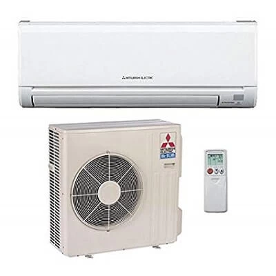
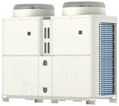
Mitsubishi Electric Corporation was established in 1921 and worked its way to becoming a leading multinational electrical equipment and electronics manufacturer. With its headquarters in Tokyo, there was a time the company only focused on elevators, escalators, and high-end appliances such as air conditioners. While the company has grown, these three remain to be their top candidates.
When it comes to air conditioning the company offers ac systems such as room air conditioners, package air conditions, VRF systems, Ventilators, air curtains, and so on. Along with endless home and commercial appliances that start with toasters and ends with elevators and moving walks. With its main focus on air conditioners, Mitsubishi is one of the leading designers, manufacturers, and providers in the world. Yet, there are times when customers find themselves baffled by a random code on their appliance.
To help you out we have listed down some of the most common error codes for Mitsubishi Air conditioners. Start by noting down the error code, and match it using the list below. Once you have the error code you can understand the main issue with your Mitsubishi air conditioner, and draw out a solution that works to your advantage.
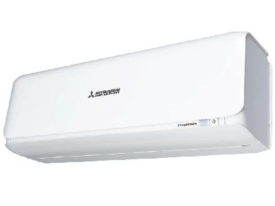
Mr Slim P Series (A)
Mr. Slim P-Series ductless heat pumps and air conditioners are compact yet powerful, offering unrivaled energy efficiency and design flexibility. Their advanced technology has been designed and tested to withstand the extremes of the Canadian climate in order to deliver a reliable and proven climate control system that you can trust all year round. With a variety of models to choose from, there’s a P-Series solution for any commercial application.
| Fault Codes | Problem |
|---|---|
| A0 | Duplicate address — Lossnay units attached with the same address — change addresses and reset the units power |
| A2 | Hardware error of transmission processor (Lossnay) — check comms wiring, and for possible Lossnay board fault |
| A3 | Line busy no data could be transmitted for 8 minutes — check A- M-Net connections (TB7 and TB3) |
| A6 | Communication error with communication processor — Lossnay address not transmitted — check M-Net voltage |
| A7 | No ACK signal — check A- M-Net wiring, range of transmission wiring exceeded or if faulty A- M-Net converter |
| A8 | M-Net no response — check A- M-Net wiring, range of transmission wiring exceeded, faulty A- M-Net converter or if incorrect wire used for M-Net connection |
| EA | Mis-wiring/loose inter-connecting cables. Noise interference |
| EB | Mis-wiring/loose interconnecting cables. Noise interference. Wrong cable size/spec |
| EC | Start-up time over. The unit has failed to initialise after power up. Noise interference. Wrong cable size/spec |
| ED | Serial communication error. Comms error between boards on outdoor unit caused by M-Net interface board incorrectly fitted |
| EF | Non-defined error code. Noise interference — power down outdoor unit for 30 seconds then switch back on |
| E0 | Remote controller communication error — check wiring, connections and comms voltage. Also check Master/Slave settings if multiple systems are connected |
| E1 | Remote controller issue — if grouped, check addressing. If twinned, check wired to master indoor only |
| E2 | Remote controller issue — if grouped, check addressing. If twinned, check wired to master indoor only |
| E3 | Remote controller issue — not transmitting — if grouped, check addressing. If twinned check wired to master indoor only |
| E4 | Remote controller issue — not receiving — if grouped, check addressing. If twinned, check wired to master indoor only |
| E5 | Remote controller issue — not receiving — if grouped, check addressing. If twinned, check wired to master indoor only |
| E6 | Indoor/outdoor communication error, mainly caused by outdoor unit being powered up before indoor unit. Drain pump being wired into S1 and S2 causes interference |
| E7 | Comms fault between I/C and O/C — check for condensate pump at I/C, reset power to O/C, check 12/24Vdc on S2 and S3 possible I/C board failure |
| E8 | Comms failure indoor to outdoor (S2/S3) — check pumps wired in, check indoor isolator and re-power in the correct sequence i.e. indoor then outdoor |
| E9 | Comms failure indoor to outdoor (S2/S3) — check pumps wired in, check indoor isolator and re-power in correct sequence i.e. indoor then outdoor |
| FA | 51CM connector open — check thermal relay for disconnection or contact failure. Possible defective board |
| F1 | Reverse phase detection — check power supply, try swapping 2 phases round. Possible defective board |
| F2 | L3 phase open — check power supply, also check for open circuit protection devices |
| F3 | 63L open — check low pressure switch for disconnection or contact failure. Possible defective board |
| F4 | 49C open — compressor inner thermostat for open circuit or contact failure |
| F5 | 63H open — check high pressure switch for disconnection or contact failure. Possible defective board |
| F7 | Phase detection circuit fault — faulty outdoor board |
| F8 | No input detected at outdoor unit — outdoor board defective |
| F9 | Two or more protection devices are open — check protection devices for disconnection or contact failure |
| P1 | Return air thermistor fault (TH1) — check if TH1 disconnected or open or close circuit |
| P2 | Liquid pipe thermistor fault (TH2) check if TH2 disconnected or open or close circuit |
| P4 | Drain sensor fault — DS open or close circuit |
| P5 | High condensate level — drain pump failure or blockage in the drain |
| P6 | Freezing/Overheating of indoor unit heat exchanger — mainly caused by reduced air flow through indoor coil. Dirty filters. Fan motor problem. Blockage |
| P8 | Abnormal pipe temperature — mainly caused by refrigerant leakage. Possibility that the thermistor mounted incorrectly |
| P9 | TH5 condenser/evaporator thermistor open/close circuit. Disconnected from the board |
| U1 | High pressure trip — outdoor fan failure, blocked coil, blockage in the system, blocked filters on indoor in heating etc |
| U2 | High discharge temperature — compressor over heating due to lack of refrigerant, faulty thermistor, high ambient running conditions. Can also be caused by 49C (comp inner thermostat or external Klixon ) tripping |
| U3 | Discharge thermistor fault |
| U4 | Outdoor thermistor fault |
| U5 | Inverter heat sink temperature too high (TH8) — check for lack of air flow around heat sink, no silicone paste, faulty thermistor (temperature can be read from service tool (or PAR21 on power inverter model)) |
| U6 | Compressor over current — carry out inverter output test and electrical checks to the compressor |
| U7 | Low discharge superheat — check TH4 reading is correct. Check LEV operations |
| ho | -For about 2 minustes following power-on, operation of the remote controller is not possible deu to system start-up. — Connector for the outdoor unit’s protection device is not connected. -Reserve or open phase wiring for the outdoor unit’s power terminal block (L1,L2,L3). -Incorrect wiring between indoor and outdoor units (incorrect polarity of S1,S2,S3). -Remote controller wire short. |
| FFFF | No unit. Buzzer sound: Triple beep. Operation Led: No lit. |
| U0-UP | Outdoor unit error. |
| F1-FA | Outdoor unit error. |
| E0-E5 | Signal error between remote controller and indoor units. |
| E6-EF | Communication error between indoor and outdoor units. |
| — | No alarm history. |
Mr Slim P Series (K)
Mr. Slim P-Series is the ductless solution for demanding environments that require an efficient and reliable heating or cooling system. P-Series ductless systems are stylish, compact, and more attractive than traditional systems. Advanced technology also means your Mr. Slim ductless system will run more efficiently than a conventional unit, saving you from rising energy costs.
| Fault Codes | Problem |
|---|---|
| EO | System transmission error — check for possible comms fault between I/C and R/C, could also be incorrect group or master/slave settings (check CN40, SW2 and SW6) |
| P1 | TH1 fault — check return air thermistor (6.4K_ @ 20°C) |
| P2 | TH2 fault — check coil/pipe thermistor (6.4K_ @20°C) |
| P3 | System transmission error — check for possible comms fault between I/C and R/C, could also be incorrect group or master/slave settings (check CN40, SW2 and SW6) |
| P4 | Drain sensor fault — check drain sensor resistance, connection and continuity |
| P5 | Drain fault — unit has detected high condensate — check for blockage in drain or tray, pump failure or sensor fault |
| P6 | Frost protection in cooling/Overheat protection in heating — detected by indoor coil sensor — general causes are lack of air flow or refrigerant charge problem |
| P7 | System error — address setting fault — check CN40 SW2 and SW6. Potential board issue |
| P8 | Abnormal pipe/coil temperature — no temperature change at indoor unit after 9 minutes of operation. General causes are outdoor unit tripped, problem with refrigerant charge or lack of air flow at the indoor unit. TH2 faulty or not mounted correctly |
| LD1 | Reverse phase on mains supply — change phases around, check for potential board problem |
| LD2 | Component open circuit — check CH, 52C, 21S4, SV, 63H and 26C for open circuit or disconnected |
| LD3 | Outdoor coil thermister is open or short circuit may be disconnected or outdoor board fault |
| LD4 | 63H high pressure switch open — investigate high pressure causes, 63H switch disconnected |
| LD5 | 51CM overcurrent relay open — compressor locked or pulling too much current — check power supply |
| LD6 | 26C thermal switch open — check if refrigerant level low or if 26C is disconnected |
| LD7 | Overheat protection — coil temp has exceeded 67°C — reduced airflow through condenser — check for fan motor problem or thermistor problem |
| LD8 | Input circuit of outdoor board — replace the outdoor board |
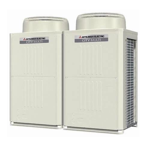
Multi City VRF
The CITY MULTI S series (for small applications) and Y series (for large applications) make use of a two-pipe refrigerant system, which allows for system changeover from cooling to heating, ensuring that a constant indoor climate is maintained in all zones.
| Error Codes | Problem |
|---|---|
| 403 | Comms fault between boards — check inverter error detail for which 2 boards, check transformer, bus voltage and inter-connecting cables |
| 900 | Lossnay unit in test run |
| 1102 | High compressor discharge temperature. Discharge temperature has exceeded 110°C or more. Short of refrigerant. Discharge thermistor |
| 1111 | Low pressure/temperature fault — check thermistors (TH2, TH3, TH4), gas charge, indoor fan, heat exchanger and filter |
| 1112 | Low pressure/temperature fault — check thermistors (TH2, TH3, TH4), gas charge, indoor fan, heat exchanger and filter |
| 1113 | Low pressure/temperature fault — check thermistors (TH2, TH3, TH4), gas charge, indoor fan, heat exchanger and filter |
| 1202 | Preliminary fault to 1102 |
| 1204 | Preliminary heat exchanger gas temperature sensor fault — check thermistors 10a and 10b |
| 1205 | Preliminary thermistor fault (TH5) |
| 1211 | Preliminary thermistor fault (TH2) |
| 1214 | Preliminary thermistor fault (THHS) |
| 1216 | Preliminary thermistor fault (TH7) |
| 1217 | Preliminary thermistor fault (TH8) |
| 1219 | Preliminary thermistor fault (TH9) |
| 1221 | Preliminary thermistor fault (TH6) |
| 1243 | Preliminary thermistor fault (TH10) |
| 1301 | Low pressure fault (63L operation) low pressure sensor sensing less than 1 bar immediately before starting |
| 1302 | High pressure fault — check pressure in system for more than 29 bar (R407c) 38 bar (R410A). Check high pressure sensor against gauge pressure |
| 1368 | Pressure sensor fault (PS1) at BC — compare pressure reading on SW1 on O/C |
| 1370 | Pressure sensor fault (PS3) at BC — compare pressure reading on SW1 at O/C |
| 1402 | Preliminary fault to 1302 |
| 1500 | System overcharge. Abnormal low compressor superheat — discharge thermistor TH4 |
| 1501 | High compressor shell temp — check for shortage of gas, insufficient indoor index running (comms room units) |
| 1505 | Suction pressure abnormal — generated by low pressure sensor detecting a vacuum — check for blockage, closed valve or sensor fault |
| 2500 | Detecting lack of water flow on a water circuit |
| 2502 | I/C has water level in drip tray, when the unit was running in cooling (temperature sensors — check for open or closed circuit and operation of pump) |
| 2503 | I/C has water level in drip tray when the unit was running in cooling (float sensor — check for closed circuit on float switch and operation of pump) |
| 2600 | Water leak from humidifier |
| 4100 | Compressor over current protection on Mr Slim with M-net interface — check inverter or compressor |
| 4101 | Compressor over current protection on Mr Slim with M-net interface — check inverter or compressor |
| 4102 | Open phase fault — check power supply and noise filter for loss of phase, check wiring and fuses |
| 4103 | Reverse phase fault — check phase rotation, loss of phase through the noise filter, fuse blown and high pressure switch open at power on |
| 4106 | Transmission power supply fault — check wiring, high current, incorrect voltage on transmission line and/or M-Net board |
| 4108 | Over current protection on DOL compressor — check power supply, contactor and compressor |
| 4115 | Power supply abnormal — check power, fuses, connections and PCB |
| 4116 | Fan motor abnormal — check fan motor and board (relates to indoor unit or Lossnay unit) |
| 4124 | Thermal switch (49C) open circuit on Mr Slim on M-Net — reset and check pressures and air flow |
| 4210 | Compressor over current problem — check inverter balance. Compressor and inverter |
| 4220 | Low inverter board BUS voltage. Less than 289VdcDC is detected. — check mains supply |
| 4225 | Low DC voltage on Vdc on fan inverter — check CNVdc for 300Vdc on diode stack and check mains power supply to outdoor unit |
| 4230 | High temperature on heat sink on inverter — check for blockages in air duct, failure of INV fan or failure of thermistor |
| 4235 | Fan inverter heat sink overheat protection. Reduced airflow through heat sink. Fan motor problem. THHS thermistor problem |
| 4240 | Over current protection. If high current is detected for more than 10 minutes — check inverter balance. Reduced airflow through heat sink |
| 4245 | Over current protection. Possible ACCT current sensor fault. Should read 280 ohms between pins 1 & 2 and across pins 3 & 4 |
| 4250 | Over current protection. Inverter IPM problem. Compressor lock — check inverter balance |
| 4255 | Inverter cooling fan problem — if high static fan is used then check that SW3-9 is on |
| 4260 | Preliminary inverter heat sink overheat protection. Reduced airflow through heat sink. Fan motor problem. THHS thermistor problem |
| 5101 | Thermistor fault at indoor/outdoor unit — check fault code address |
| 5102 | Thermistor fault at indoor/outdoor unit — check fault code address |
| 5103 | Thermistor fault at indoor/outdoor unit — check fault code address |
| 5104 | Thermistor fault at indoor/outdoor unit — check fault code address (indoor fault — check SW7-3 is off) |
| 5105 | TH5 open/short circuit — check if the TH is disconnected from the board |
| 5106 | TH6 open/short circuit — check if the TH is disconnected from the board |
| 5107 | TH7 open/short circuit — check if the TH is disconnected from the board |
| 5108 | TH8 open/short circuit — check if the TH is disconnected from the board |
| 5109 | TH9 open/short circuit — check if the TH is disconnected from the board |
| 5110 | TH10 open/short circuit — check if the TH is disconnected from the board |
| 5111 | BC box thermistor error — TH11 open/short circuit, disconnected from board/pipe |
| 5112 | BC box thermistor error — TH10 open/short circuit, disconnected from board/pipe |
| 5113 | BC box thermistor error — TH open/short circuit, disconnected from board/pipe |
| 5114 | BC box thermistor error — TH open/short circuit, disconnected from board/pipe |
| 5115 | BC box thermistor error — TH15 open/short circuit, disconnected from board/pipe |
| 5116 | BC box thermistor error — TH16 open/short circuit, disconnected from board/pipe |
| 5201 | Pressure sensor fault outdoor unit/BC box — check fault code address/SW1 pressure sensor readings |
| 5202 | Pressure sensor fault (PS2) in the BC box |
| 5203 | Pressure sensor fault (PS3) in the BC box |
| 5300 | A-Control UH fault — see Mr Slim fault code list |
| 5301 | Current sensor fault, ACCT or DCCT — check inv. error details |
| 5401 | Temperature sensor fault — check CN30 for humidity sensor |
| 5701 | Loose float switch connector — check switch, check CN4F on indoor unit |
| 6201 | TB7 transmission line communication error — check for voltage abnormality/short |
| 6202 | Transmission processor hardware error — check for noise/short on M-Net cable |
| 6600 | Repeat address fault — two or more units are assigned the same address — correct the repeated address |
| 6601 | Polarity setting error — no voltage or short circuit on the m-net transmission line |
| 6602 | Hardware error of transmission processor. Noise interference. Polarity problem on TB7 |
| 6603 | Bus circuit busy — check if indoor unit, Lossnay unit or anything else has been wired into TB7, instead of TB3 |
| 6607 | Communication issue — no response back from unit whilst system is operational |
| 6608 | Communication error — loss of voltage or noise entering the transmission line |
| 6700 | K control communication error — R22 type unit connected onto M-Net circuit comms error |
| 6701 | K control communication error — R22 type unit connected onto M-Net circuit comms error |
| 6702 | K control duplicate address error — two or more R22 type units connected onto M-Net circuit with the same address |
| 6750 | K control communication error — R22 type unit connected onto M-Net circuit comms error |
| 6751 | R22 R/A thermistor fault (P1) |
| 6752 | R22 frost protection at I/C (P6) |
| 6753 | Comms fault between O/C and I/C |
| 6754 | R22 drain fault (P5) |
| 6755 | R22 drain fault (P5) |
| 6756 | R22 frost protection at I/C (P6) |
| 6757 | System error |
| 6758 | Comms fault between I/C and O/C |
| 6761 | R22 R/A thermistor fault (P1) |
| 6762 | R22 TH2 fault check resistance (P2) |
| 6763 | R22 Comms fault between I/C and O/C |
| 6764 | R22 drain fault (P4) |
| 6765 | R22 drain fault (P5) |
| 6766 | R22 frost protection at I/C (P6) |
| 6767 | R22 comms fault between I/C and O/C |
| 6771 | K abnormality — high pressure abnormality or low pressure abnormality |
| 6772 | K abnormality — inner thermostat function, discharge temperature abnormality, shell thermostat function, over current protection |
| 6773 | K abnormality — radiator plate thermostat function |
| 6774 | K abnormality — outdoor thermistor abnormality |
| 6775 | K abnormality — pressure sensor abnormality, indoor/outdoor communication error |
| 6776 | K abnormality — over current shut-off |
| 6777 | K abnormality — system error |
| 6778 | K abnormality — normal |
| 6779 | K abnormality — refrigerant overcharge, abnormal voltage, abnormal CT sensor |
| 6830 | Comms fault between I/C and R/C check connections to MA R/C and check for 12Vdc check R/C not set sub controller |
| 6831 | MA R/C communication fault — check connections on TB15 or that the controller was removed while the I/C was powered |
| 6832 | MA controller comms fault — check cable length no bigger than 500m, check connection and type of cable used, check R/C not set sub on field settings |
| 6833 | MA controller comms fault check cable length no bigger than 500m, check connection and type of cable used, check R/C not set sub on field settings |
| 6834 | MA Controller comms fault — check cable length no bigger than 500m, check connection and type of cable used, check R/C not set sub on field settings |
| 6840 | A-Control E6/E8 fault — see Mr Slim fault code list |
| 6841 | A-Control E7/E9 fault — see Mr Slim fault code list |
| 6844 | A-Control EA fault — see Mr Slim fault code list |
| 6845 | A-Control Eb fault — see Mr Slim fault code list |
| 6846 | A-Control EC fault — see Mr Slim fault code list |
| 7100 | Over capacity — (R2 150% index exceeded) (Y 130% index exceeded) |
| 7101 | Capacity setting error — SW2 set wrong on indoors, SW5 on YHMA outdoor, (SW3-10 on older kit) |
| 7102 | Error in number of connected units — loss of M-Net voltage (short or break), no power to BC, wrong SW5 setting on box, wrong box type |
| 7105 | Address setting error — OC or BC addressed wrong |
| 7106 | Attribute setting error — SW3-1 setting on a GUF |
| 7107 | Port setting error — check if too much capacity on a single port, wiring SW2 setting, wrong SW14 setting or wrong units on a box when using multiple boxes |
| 7110 | Check SW5-7 is correctly set |
| 7111 | Remote control sensor fault — SW1 — 1 on and no controllers fitted or faulty remote controller |
| 7113 | Function setting error — wrong SW5 setting or wrong resistors fitted on YHM-A |
| 7117 | Model setting error — SW5 set wrong or wrong resistors in |
| 7130 | Incompatible equipment on M-Net — check split with MAC 399 wired onto the TB5 line TB5 line, not the TB7 |
Cassette AC

| Alarm Codes | Solutions |
|---|---|
| P1 | Intake sensor error |
| P2 | Pipe (TH2) sensor error |
| P9 | Pipe (TH5) sensor error |
| E6,E7 | Indoor/outdoor unit communication error |
| P4 | Drain sensor error/Float switch connector (CN4F) open |
| P5 | Drain pump error |
| PA | Forced compressor stop (due to water leakage abnormality) |
| P6 | Freezing/Overheating protection operation |
| EE | Communication error between indoor and outdoor units |
| P8 | Pipe temperature error |
| E4,E5 | Remote controller signal receiving error |
| Fb | Indoor unit control system error (memory error, etc.) |
| PL | Refrigerant circuit abnormal |
| E0,E3 | Remote controller transmission error |
| E1,E2 | Remote controller control board error |
| E9 | Indoor/outdoor unit communication error (Transmitting error) (Outdoor unit) |
| UP | Compressor overcurrent interruption |
| U3,U4 | Open/short of outdoor unit thermistors |
| UF | Compressor overcurrent interruption (When compressor locked) |
| U2 | Abnormal high discharging temperature/49C operated/ insufficient refrigerant |
| U1,Ud | Abnormal high pressure (63H operated)/Overheating protection operation |
| U5 | Abnormal temperature of heat sink |
| U8 | Outdoor unit fan protection stop |
| U6 | Compressor overcurrent interruption/Abnormal of power module |
| U7 | Abnormality of super heat due to low discharge temperature |
| U9,UH | Abnormality such as overvoltage or voltage shortage and abnormal synchronous signal to main circuit/Current sensor error |
Ecodan
Ecodan air source heat pumps use 1kW of electrical energy input and take 2.2kW of low temperature renewable heat energy from the air, producing a high efficient 3.2kW heat energy output. This heats refrigerant in the system which in turn heats water for domestic hot water and space heating.

| Fault Codes | Problem |
|---|---|
| F3 | Low pressure switch failure — check connection on the board and continuity of switch |
| F5 | High pressure switch failure — check connection onto board and continuity of switch |
| F9 | Both pressure switch contacts are open at the same time — check connection onto board and continuity of switch and for a potential board failure |
| EA | Mis-wiring fault between FTC and Ecodan — check S1,S2,S3 also check voltages and comms |
| EB | Mis-wiring fault between FTC and Ecodan — Check S1,S2,S3 also check voltages and comms |
| EC | Unit cannot finish start up process — generally caused by a comms fault |
| U1 | Ecodan high pressure fault — mainly caused by incorrect water flow rates — check with flow setter |
| U2 | Ecodan high compressor discharge temperature — mainly caused by refrigerant shortage or dirty condenser |
| U3 | Ecodan discharge thermistor problem — mainly caused by TH4 discharge thermistor — open/close circuit |
| U4 | Open or close circuit Ecodan thermistors (TH3, TH32, TH33, TH6, TH7, TH8) — open or close circuit or disconnected from main board |
| U5 | Inverter heat sink overheat protection (W50 and W85 models 77°C, HW140 model 95°C — reduced air flow through Ecodan — faulty fan motor |
| U6 | Inverter/Compressor over current — system indicates possible IPM error |
| U8 | Ecodan fan motor problem — mainly caused by DC fan motor being disconnected, connected or obstructed with the power on or possible main board fault |
| U9 | Over voltage or under voltage — mainly caused by either CN2 or CN5 loose or disconnected or decrease of mains power supply |
| UD | Overheat protection TH3 ≥ 70°C or 63HS ≥ 70°C saturation temperature |
| UF | Compressor over current/Compressor lock — occurs within 30 seconds of compressor start |
| UH | Abnormal running current — < 1A or > 40A detected during operation — check CN5 connections |
| UL | Open circuit (63L ) |
| UP | Over current detected after 30 seconds of operation — do an inverter test to determine outputs balanced |
| E0 | Transmitting Error PAR W21 — check refrigerant address on SW1 of Ecodan |
| E1 | Faulty controller |
| E3 | Transmitting Error (PAR W21) — check refrigerant address on SW1 of Ecodan |
| E4 | Receiving Error (PAR W21) — check refrigerant address of SW1 on Ecodan |
| E5 | Receiving Error (PAR W21) — check refrigerant address of SW1 on Ecodan |
| E6 | Indoor/Outdoor communication error — mainly due to Ecodan being powered up before FTC(2) |
| E8 | Indoor/Outdoor communication error — mainly due to Ecodan being powered up before FTC(2) |
| E9 | Indoor/Outdoor communication error — mainly due to Ecodan being powered up before FTC(2) |
| EF | Non-defined error code — noise interference — power down Ecodan for 30 seconds then switch back on |
| ED | Serial communication fault between Ecodan main board and Ecodan inverter board — mainly due to loose CN2 or CN5 cable |
| P1 | Flow temp sensor fault — TH1 not connected, short or open circuit |
| P6 | Over heating at heat exchanger — lack of water flow, air in the system, flow rate incorrectly set, blockage or pump problem |
| P8 | No temp change at plate heat exchanger — problem with flow rate (too high) — incorrect sizing of system |
| P9 | TH5 Fault — TH5 not connected, short or open circuit, FTC not configured for heating only |
| PE | Inlet water temp fault — TH32 is below 10°C whilst compressor is in operation — possible thermistor out of range, short of gas, incorrect sizing of radiator or problem in the water circuit (blockage, pump failure etc) |
Hot Water Heat Pumps PWFY Series
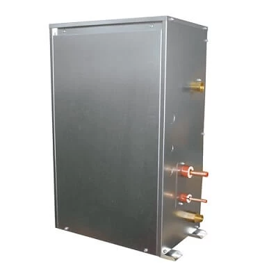
12.5kW Hot Water Module. Flexibility to create very large systems. Can be installed in conjunction with City Multi VRF air conditioning. Available in one size: PWFY-P100VM-E-BU (12.5kW heating) which is modular to allow creation of larger solutions. Sanitary water heating has suitable applications in: hotels and motels, apartments, commercial kitchens and laundries, office buildings, food processing industry, heat recovery from air conditioning systems into sanitary water storage, and direct sanitary water heating is also possible.
| Fault Codes | Problem |
|---|---|
| 403 | Comms fault between boards — check between control board an inverter board |
| 403 | Comms fault between boards — check between control board an fan board |
| 1102 | High compressor discharge temperature — discharge temp has exceeded 115°C or more — check if short of refrigerant or discharge thermistor |
| 1301 | Low pressure fault — low pressure sensor sensing less than 1 bar immediately before starting |
| 1302 | High pressure fault — check system pressure exceded 32.3 bar, check high pressure sensor (63HS) against gauge pressure |
| 2000 | Pump interlock error — pump interlock open whilst system in operation |
| 2134 | Abnormal water temperature (TH6) has exceded 85°C |
| 2135 | Water source heat exchanger frozen (TH6) or (TH8) reading 2°C |
| 4102 | Open phase fault — check power supply and noise filter for loss of phase, check wiring and fuses |
| 4115 | Power supply abnormal — check power, fuses, connections and PCB |
| 4220 | Low inverter board BUS voltage — less than 200Vdc is detected during in inverter operation — check mains supply |
| 4220 | Bus voltage error PAM damage — replace the inverter board |
| 4220 | High bus voltage Vdc>380v — check power supply and possible faulty inverter board |
| 4220 | Replace inverter board |
| 4230 | High temperature (85°C) on heat sink on inverter — check for blockages in air duct, failure of INV fan failure of INV fan or failure of thermistor (THHS) |
| 4250 | Over current protection — inverter IPM problem or compressor lock — check inverter balance |
| 4250 | ACCT sensor over current detection 34.5A peak or 16A rms is detected — check the compressor for failure, or possible inverter board failure |
| 5102 | Thermistor TH22 failure |
| 5103 | Thermistor TH13 or TH23 failure |
| 5104 | Thermistor TH11 failure |
| 5106 | Thermistor TH6 failure |
| 5108 | Thermistor TH8 failure |
| 5110 | Thermistor THHS failure |
| 5201 | High pressure sensor fault — check the system pressure is >1 bar, check the operation of 63HS high pressure transducer |
| 5202 | Pressure sensor fault |
| 5301 | Current sensor fault, ACCT or DCCT — check inv. error details |
| 5301 | Low output current <1.5A rms whilst the inverter is in operation |
Packaged Hot Water Heat Pump CAHV
45kW Packaged Hot Water Heat Pump. Can be combined to max. 70kW. “Flash-injection Circuit”, which is designed for our ZUBADAN CITY MULTI (air conditioning system for cold regions), is mounted in our new Hot Water Heat Pump. By utilizing our advanced “Flash-injection Circuit” and the latest high-efficiency compressor, Hot Water Heat Pump provides hot water upto 70°C, and produces less capacity drop at low outdoor temperature.
| Error Codes | Problem |
|---|---|
| AFSA | Water supply cut-off (flow switch has been triggered) — check flow switch and wiring |
| AHP1 | High pressure fault — check water flow, possible high pressure sensor fault LEV fault |
| AdSH | Compressor crank case temperature of 10°C or less for 40 minutes while compressor in operation — check for possible failure of fan motor, low pressure sensor, compressor shell thermistor, high pressure sensor, discharge thermistor (TH1 TH5), LEV or SV2 |
| 1303 | Low pressure protection low pressure below 6 bar within 30 sec of start up — possible failure of LP sensor, air inlet thermistor fault (TH4 TH8), suction temperature (TH2 TH6), LEV bypass check valve |
| 1103 | Compressor shell bottom temperature exceeded 80°C detected whilst compressor running |
| 5109 | Compressor shell thermistor faulty (TH3 TH6), LEV failure |
| 5110 | Outside temperature thermistor fault — check TH9 |
| 5112 | Water inlet temperature — check TH10 main circuit |
| 5111 | Water inlet temperature — check TH12 sub circuit |
| 5113 | Outlet water temperature — check TH11 main circuit |
| 5103 | Outlet water temperature — check TH12 sub circuit |
| 5107 | Compressor shell temperature — check TH3 main circuit |
| 5101 | Compressor shell temperature — check TH7 sub circuit |
| 5105 | Discharge temperature — check TH1 main circuit |
| 5102 | Discharge temperature — check TH5 sub circuit |
| 5106 | Inlet temperature — check TH2 main circuit |
| 5104 | Inlet temperature — check TH6 sub circuit |
| 5108 | Air to refrigerant heat exchanger inlet temperature — check TH4 main circuit |
| 5114 | Air to refrigerant heat exchanger inlet temperature — check TH8 sub circuit |
| 5115 | Common return water when using multiple outdoors — check TH14 |
| 5117 | Common return water when using multiple outdoors — check TH15 |
| 5118 | High pressure sensor or high pressure fault — check 63HS sensor or 63H (hp switch) |
| 7113 | Low pressure sensor low or low pressure fault — check 63LS |
| 7117 | Model setting error 1 — mis-set switch |
| 4115 | Model setting error 2 — faulty Z21 resistor |
| A471 | Power supply frequency fault — power supply frequency is not 50Hz or 60Hz |
| 1104 | Discharge temperature fault — 120°C detected during compressor operation — check water flow, pump, high pressure sensor fault or LEV fault |
| AC61 | Power supply fault — check transmission power supply or if PCB faulty |
MR Slim Operation Light Blinking
Flashing of POWER lamp indicates abnormalities. Before taking measures, make sure that the symptom reappears for accurate troubleshooting. Self check table
When the indoor unit has started operation and the above detection method has detected an abnormality (the first detection after the power ON), the indoor electronic control P.C. board turns OFF the indoor fan motor with OPERATION INDICATOR lamp flashing.
| Indicator lamp | Solution |
|---|---|
| POWER lamp flashes. 0.5-second ON | Mis-Wiring or serial signal. Outdoor unit does not operate. When the serial signal form the outdoor unit is not received for a maximum of 6 minutes. |
| POWER lamp lights up | Out door control system. Outdoor unit does not operate. When it cannot properly read data in the nonvolatile memory of the inverter P.C. board or the outdoor electronic control P.C. board. Check the blinking pattern of the LED on the inverter P.C. board or the outdoor lectronic control P.C. board. |
| POWER lamp flashes. 2-time flash | Indoor coil thermistor. Room temperature thermistor. Indoor unit and outdoor unit do not operate. When the indoor coil or the room temperature thermistor is short or open circuit. |
| POWER lamp flashes. 3-time flash | Indoor fan motor. Indoor unit and outdoor unit do not operate. When the rotational frequency feedback signal is not emit during the indoor fan operation. |
| POWER lamp flashes. 5-time flash | Out door power system. Indoor unit and outdoor unit do not operate. When it consecutively occurs 3 times that the compressor stops for overcurrent protection or start-up failure protection witth in 1 minute after start-up. |
| POWER lamp flashes. 6-time flash | Outdoor thermistors. Indoor unit and outdoor unit do not operate. When the outdoor thermistors short or open circuit during the compressor operation. |
| POWER lamp flashes. 7-time flash | Out door control system. Indoor unit and outdoor unit do not operate. When it cannot properly read data in the nonvolatile memory of the inverter P.C. board or the outdoor electronic control P.C. board. |
| POWER lamp flashes. 14-time flash | Other abnonmality. Indoor unit and outdoor unit do not operate. An abnormality other than above mentioned is deteced. Confirm the abnormarity in detail using the failure mode recall function. |
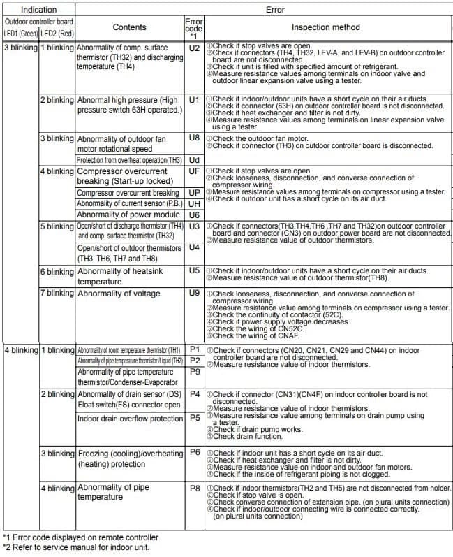
Split AC Timer Light Blinking
| Trouble | Contents |
|---|---|
| 3 blinking-1 blinking | Abnormality of comp. surface thermistor (TH32) and discharging temperature (TH4) |
| 3 blinking-2 blinking | Abnormal high pressure (High pressure switch 63H operated.) |
| 3 blinking-3 blinking | Abnormality of outdoor fan motor rotational speed. Protection from overheat operation(TH3). |
| 3 blinking-4 blinking | Compressor overcurrent breaking (Start-up locked). Compressor overcurrent breaking. Abnormality of current sensor (P.B.). Abnormality of power module. |
| 3 blinking-5 blinking | Open/short of discharge thermistor (TH4) and comp. surface thermistor (TH32). Open/short of outdoor thermistors (TH3, TH6, TH7 and TH8). |
| 3 blinking-6 blinking | Abnormality of heatsink temperature |
| 3 blinking-7 blinking | Abnormality of voltage |
| 4 blinking-1 blinking | Abnormality of room temperature thermistor (TH1). Abnormality of pipe temperature thermistor /Liquid (TH2). Abnormality of pipe temperature thermistor/Condenser-Evaporator. |
| 4 blinking-2 blinking | Abnormality of drain sensor (DS) Float switch(FS) connector open. Indoor drain overflow protection. |
| 4 blinking-3 blinking | Freezing (cooling)/overheating (heating) protection |
| 4 blinking-4 blinking | Abnormality of pipe temperature |
Aircon RedLINK Codes
| Error Codes | Meaning |
|---|---|
| E0 27 | Verify device temperature is within operating range. If within range for at least 30 minutes and problem persists, replace Remote Controller. |
| E0 91 | Communication was established between wireless receiver and the indoor unit, but communication has been lost for 10 minutes. Check cable connection. Try replacing the cable. |
| E1 29 | Attempting to connect incompatible wireless devices. |
| E1 34 | Low signal strength. Move wireless device to a different location and try again. |
| E1 38 | Make sure Connect light on wireless receiver is flashing and you are 2+ feet away from wireless receiver. |
| E1 54 | Indoor unit does not support wireless receiver. |
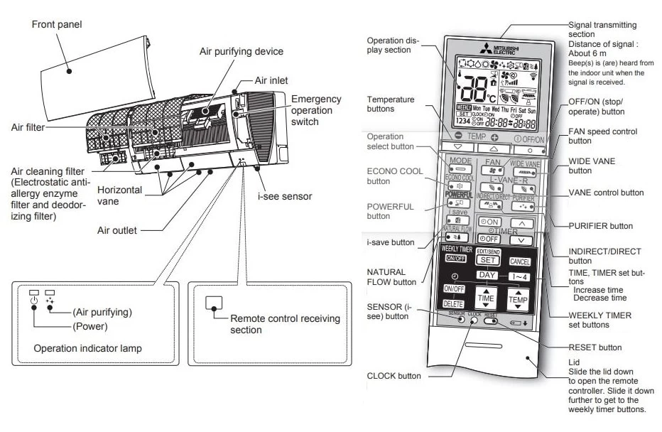
Troubleshooting
Even if these items are checked, when the unit does not recover from the trouble, stop using the air conditioner and consult your dealer.
Symptom: The unit cannot be operated.
Explanation & Check points:
- Is the breaker turned on?
- Is the power supply plug connected?
- Is the ON timer set?
Symptom: The horizontal vane does not move.
Explanation & Check points:
- Are the horizontal vane and the vertical vane installed correctly?
- Is the fan guard deformed?
- When the breaker is turned on, the horizontal vanes’ position will be reset in about a minute. After the reset has completed, the normal horizontal vanes’ operation resumes. The same is true in the emergency cooling operation.
Symptom: The airfl ow direction changes during operation. The direction of the horizontal vane cannot be adjusted with the remote controller.
Explanation & Check points:
- When the unit is operated in COOL or DRY mode, if the operation continues with air blowing down for 0.5 to 1 hour, the direction of the airfl ow is automatically set to horizontal position to prevent water from condensing and dripping.
- In the heating operation, if the airfl ow temperature is too low or when defrosting is being done, the horizontal vane is automatically set to horizontal position.
Symptom: Water leaks from the outdoor unit.
Explanation & Check points:
- During COOL and DRY operations, pipe or pipe connecting sections are cooled and this causes water to condense.
- In the heating operation, water condensed on the heat exchanger drips down.
- In the heating operation, the defrosting operation makes ice forming on the outdoor unit melt and drip down.
Symptom: The display on the remote controller does not appear or it is dim. The indoor unit does not respond to the remote control signal.
Explanation & Check points:
- Are the batteries exhausted?
- Is the polarity (+, -) of the batteries correct?
- Are any buttons on the remote controller of other electric appliances being pressed?
Symptom: The room cannot be cooled or heated sufficiently.
Explanation & Check points:
- Is the temperature setting appropriate?
- Is the fan setting appropriate? Please change fan speed to High or Super High.
- Are the fi lters clean?
- Is the fan or heat exchanger of the indoor unit clean?
- Are there any obstacles blocking the air inlet or outlet of the indoor or outdoor unit?
- Is a window or door open?
- It may take a certain time to reach the setting temperature or may not reach that dependingon the size of the room, the ambient temperature, and the like.
Symptom: The air from the indoor unit smells strange.
Explanation & Check points:
- Are the fi lters clean?
- Is the fan or heat exchanger of the indoor unit clean?
- The unit may suck in an odor adhering to the wall, carpet, furniture, cloth, etc. and blow it out with the air.
Symptom: Weekly timer does not operate according to settings.
Explanation & Check points:
- Is the ON/OFF timer set?
- Transmit the setting information of the weekly timer to the indoor unit again. When the information is successfully received, a long beep will sound from the indoor unit. If information fails to be received, 3 short beeps will be heard. Ensure information is successfully received.
- When a power failure occurs and the main power turns off, the indoor unit built-in clock will be incorrect. As a result, the weekly timer may not work normally.
Electrical Wiring Diagram

Refrigerator Diagram
Manuals PDF
Mitsubishi Air Conditioning Service Handbook PDF
Mitsubishi Air Conditioning Service Manual PDF
Mitsubishi Electric MRCH1 Remote ControllerOperating Manual PDF
Mitsubishi Electric Split AC Manual MSZ-AP22VGD PDF
Mhk1 Wireless Remote Receiver Kit Manual PDF
MIFH1, MRCH1, MCCH1, MOS1 Controller Kit Installation Manual PDF
Mitsubishi Air Conditioning Error Codes PDF – R410A Systems
- Author
- Recent Posts

Regarding error and fault codes, we believe sharing knowledge is the best way to help everyone. That is why we established ACErrorCode.com, to give you every bit of info you need as a customer. HVAC Expert Contact: dannyreese@acerrorcode.com
![]()
*If you can’t find the code you’re looking for on our site, please let us know, and we’ll update our database as soon as possible.
| Error | Расшифровка | Русский перевод |
| P1 | Intake sensor error | Ошибка датчика на входе |
| P2 | Pipe (TH5) sensor error | Ошибка датчика теплообменника ТН5 (по схеме) |
| P4 | Drain sensor error/Float switch connector (CN4F) open | Переполнение дренажного поддона, или обрыв поплавкового датчика CN4F |
| P5 | Drain pump error | Ошибка дренажной помпы |
| P6 | Freezing/Overheating protection operation | Ошибка по обмерзанию или перегреву |
| P8 | Pipe temperature error | |
| P9 | Pipe (TH2) sensor error | Ошибка по датчику теплообменника ТН2 |
| PA | Forced compressor stop(due to water leakage abnormality) | Принудительная остановка компрессора (из-за переполнения дренажной системы) |
| E0, E3 | Remote controller transmission error | Нет связи с пультом управления |
| E1, E2 | Remote controller control board error | Неисправна плата пульта управления |
| E4, E5 | Remote controller signal receiving error | |
| E9 | Indoor/outdoor unit communication error (Transmitting error) (Outdoor unit) | Нет связи между внутренним и внешним блоком (Ошибка на внешнем блоке) |
| EE | Communication error between indoor and outdoor units | Отсутствует межблочная связь между внутренним и внешним блоками |
| U1,Ud | Abnormal high pressure (63H worked)/Overheating protection operationс | Высокое давление по датчику 63Н, или защита от перегрева |
| U2 | Abnormal high discharging temperature/49C worked/insufficient refrigerant | Сработал датчик 49С, очень низкое давление нагнетания, недостаток хладагента |
| U3, U4 | Open/short of outdoor unit thermistors | Обрыв, короткое замыкание термодатчика внешнего блока |
| U5 | Abnormal temperature of heat sink | Температура конденсатора не соответствует норме |
| U6 | Compressor overcurrent interruption/Abnormal of power module | Компрессор принудительно остановлен по токовой перегрузке, неисправен силвой модуль |
| U7 | Abnormality of super heat due to low discharge temperatureAbnormal high discharging temperature/49C worked/insufficient refrigerant | Сработал датчик 49С / очень низкое давление нагнетания / недостаток хладагента |
| U8 | Outdoor unit fan protection stop | Двигатель вентилятора внешнего блока остановлен |
| U9, UH | Abnormality such as overvoltage or voltage shortage and abnormal synchronous signal to main circuit/Current sensor error | Повышенное / пониженное напряжение питания, неисправность токового датчика |
| UF | Compressor overcurrent interruption (When compressor locked) | Компрессор остановлен из-за токовой перегрузки, компрессор заклинило |
| UP | Compressor overcurrent interruption | Остановка компрессора из-за перегрузки по току |
| Fb | Indoor unit control system error (memory error, etc.) | Ошибка платы управления внутреннего блока (EEPROM и т.д.) |
Определить ошибку в бытовых сплит системах можно по миганию индикаторов на панели внутреннего блока.
Получить расшифровку всех возможных кодов холодильного оборудования Mitsubishi Electric можно на сайте:
Язык оригинальной документации — английский.
Компания Mitsubishi Electric разработала программу для телефонов с помощью которой можно получить расшифровку кода ошибок.
![]()
|
Error |
Расшифровка |
Русский перевод |
|
P1 |
Intake sensor error |
Ошибка датчика на входе |
|
P2 |
Pipe (TH5) sensor error |
Ошибка датчика теплообменника ТН5 (по схеме) |
|
P4 |
Drain sensor error/Float switch connector (CN4F) open |
Переполнение дренажного поддона, или обрыв поплавкового датчика CN4F |
|
P5 |
Drain pump error |
Ошибка дренажной помпы |
|
P6 |
Freezing/Overheating protection operation |
Ошибка по обмерзанию или перегреву |
|
P8 |
Pipe temperature error |
|
|
P9 |
Pipe (TH2) sensor error |
Ошибка по датчику теплообменника ТН2 |
|
PA |
Forced compressor stop(due to water leakage abnormality) |
Принудительная остановка компрессора (из-за переполнения дренажной системы) |
|
E0, E3 |
Remote controller transmission error |
Нет связи с пультом управления |
|
E1, E2 |
Remote controller control board error |
Неисправна плата пульта управления |
|
E4, E5 |
Remote controller signal receiving error |
|
|
E9 |
Indoor/outdoor unit communication error (Transmitting error) (Outdoor unit) |
Нет связи между внутренним и внешним блоком (Ошибка на внешнем блоке) |
|
EE |
Communication error between indoor and outdoor units |
Отсутствует межблочная связь между внутренним и внешним блоками |
|
U1,Ud |
Abnormal high pressure (63H worked)/Overheating protection operationс |
Высокое давление по датчику 63Н, или защита от перегрева |
|
U2 |
Abnormal high discharging temperature/49C worked/insufficient refrigerant |
Сработал датчик 49С, очень низкое давление нагнетания, недостаток хладагента |
|
U3, U4 |
Open/short of outdoor unit thermistors |
Обрыв, короткое замыкание термодатчика внешнего блока |
|
U5 |
Abnormal temperature of heat sink |
Температура конденсатора не соответствует норме |
|
U6 |
Compressor overcurrent interruption/Abnormal of power module |
Компрессор принудительно остановлен по токовой перегрузке, неисправен силвой модуль |
|
U7 |
Abnormality of super heat due to low discharge temperatureAbnormal high discharging temperature/49C worked/insufficient refrigerant |
Сработал датчик 49С / очень низкое давление нагнетания / недостаток хладагента |
|
U8 |
Outdoor unit fan protection stop |
Двигатель вентилятора внешнего блока остановлен |
|
U9, UH |
Abnormality such as overvoltage or voltage shortage and abnormal synchronous signal to main circuit/Current sensor error |
Повышенное / пониженное напряжение питания, неисправность токового датчика |
|
UF |
Compressor overcurrent interruption (When compressor locked) |
Компрессор остановлен из-за токовой перегрузки, компрессор заклинило |
|
UP |
Compressor overcurrent interruption |
Остановка компрессора из-за перегрузки по току |
|
Fb |
Indoor unit control system error (memory error, etc.) |
Ошибка платы управления внутреннего блока (EEPROM и т.д.) |
Код EA
Неправильный монтаж внутреннего / наружного блока. Проверить межблочное соединение, электрическая цепь. Обрыв цепи.
Код Eb
Неправильный монтаж, отключения, сработала защита.
Код ЕС
Ошибка запуск по времени, в течение 5 мин. Выключить питание, обесточить сплит систему Mitsubishi Electric, вынуть батарейки из дистанционного пульта управления. Далее проделать операцию через 5 мин. в обратном порядки.
Все настройки сплит системы вернутся к заводским по- умолчанию.
Неправильный монтаж внутреннего / наружного блоков как правило ведёт к поломкам сплит системы..
Mitsubishi Electric инверторного типа, таблица неисправностей.
Обрыв связи.
Код E6
Ошибка соединений внутреннего / наружного блока, датчик приёма сигнала (нет приема сигнала).
Сигнала нет, замыкание.
Код E7
Ошибка внутреннего / наружного ошибка блока передачи (ошибка передачи).
Сигнала нет, замыкание.
Код E8
Ошибка, не работает датчик приёма, проверить приходит ли питание к датчику.
Обрыв цепи.
Код E9
Ошибка внутреннего / наружного ошибка межблочного соединения.
Обрыв цепи. Сигнала нет.
Код E0 Нет сигнала от пульта управления (прием сигнала)
Поменяйте батарейки пульта ду.
Код E3
Не правильный сигнал. ПУ кондиционера не правильно формирует сигнал.
Исправить, — См. Код ЕС
Код Е4
Проверить межблочное соединение, целостность датчиков температуры и давления.
Код E5
Проверить напряжение в сети. Возможны сбои в работе оборудования.
Код EF
Ошибка M-NET, — нет сигнала
Проверить межблочное соединение, обрыв соединений или плохой контакт.
Код Эд
Последовательность формирования сигнала нарушена. Сбой шагового- искателя.
Исправление, — см. Код ЕС Mitsubishi Electric, — вернуться к заводским настройкам кондиционера по умолчанию.
Код P1
Не работает датчик температуры Mitsubishi Electric (TH1).
Проверить датчик на целостность. Нарушена герметичность датчика, датчик и соединительный кабель настолько грязные и мокрые, что замыкают. При необходимости заменить датчик
Код P2
Датчик обморожения внутреннего блока, сработал датчик.
Грязный внутренний блок, плохое прохождение воздуха, вследствии обморожения. Проверить контур сплит системы Mitsubishi Electric на утечку газа.
Обморожение как правило начинается из-за недостатка газа или кондиционер требует к себе внимания, — профилактики.
Код P4
Проверить дренаж, слив, — сработал датчик переполнения ванны. Забит слив.
Код P5
Не работает сток, двигатель дренажа работает в холостую.
Ремонтируем сплит системы, кондиционеры Mitsubishi Electric до 2006 года выпуска
Коды ошибок. Mitsubishi Electric до 2006 года выпуска
Код P6
Ошибка, —
Замораживание / сработала защита от перегрева. Проверить контур сплит системы на утечку газа.
Обморожение как правило начинается из-за недостатка газа.
Код P8
Температурный режим вышел за заданные параметры, проверить датчик температуры на целостность. Сопротивление датчика должно быть в пределах 16 Ом.
Код P9
Датчик температуры замкнут.
Проверить датчик на целостность. Нарушена герметичность датчика, датчик и соединительный кабель настолько грязные и мокрые, что замыкают(TH5)
Замыкание.
Код F1
Проверить фазировку на двигателе компрессора наружнего блока кондиционера Mitsubishi Electric.
Код F2
Ошибка L3 обрыв фазы.
Код F3
Ошибка 63L нет сигнала с платы управления.
проверить качество формирования сигнала, проверить датчики на целостность, возможная причина, 0 — подгорели контакты реле включения, залипания контактов, неисправность пружины реле…
Код F4
Ошибка 49C разъем разомкнут.
Код F9
Ошибка, — разъем 2 или более нет сигнала.
Код FA
Ошибка L2- обрыв фазы или 51см разъем разомкнут.
Код F7
Ошибка последовательности фаз шлейфа, проверить состояние кабеля.
Код F8
Сбои в питании, проверить напряжение в сети.
Код U2
Высокие температурные параметры работы компрессора, сработала защита от перегрузки.
Код U2
Ошибка
Внутренний термостат (49C) проверить причины сработки, проверить рабочие и пусковые токи компрессора кондиционера, напряжение питания, количество и давление газа фреона в холодильном контуре сплит системы.
Код U1
Датчик давления (высокое давление swicth 63H сработал)
Код U1
Фатальная ошибка.
Код УП
Ошибка
Высокое давление в системе, шаровой кран закрыт, залом меж.блочной трассы, не работает перепускной клапан, задир, залип…Постучать тук-тук-тук.
Код UL
Низкое давление в системе, сработал датчик.
Код Ud
Сработала тепловая защита компрессора кондиционера. Смотреть исправление и причины, — код U2
Код U6
Перегрузка компрессора. Смотреть исправление ошибки и причины, — код U2
Код UA
Ошибка компрессора. Проверить пусковое реле.
Код UF
Нет сигнала блокировка пуска. Фатальная ошибка, неисправно всё, начинай проверку сначала.
Например смотреть неисправности тык
а) неисправности электрической части, системы эл. питания и управления кондиционером. рис. 1.
б) неисправности холодильного контура, рис. 2.
Блокировка пуска компрессора, неверные входящие и разрешающие пуск параметры.
Код UH
Текущая ошибка датчика.
Код U3
Проверить конденсатор, недостаточное сглаживание по току, варистор неисправен.
Код U4
Не работает датчик температуры наружнего блока кондиционера.
Коды P1-P8 | Mitsubishi Electric .Slim K-контроль
Дисплей на пульте дистанционного управления Mitsubishi Electric.
Горит лампочка светодиода E0
Диагностика неисправности приема / передачи сигнала ошибки.
Сигнала нет, замыкание датчика.
Горит лампочка светодиода P1
Диагностика неисправности датчиков всасываемого воздуха, ошибка.
Сигнала нет, замыкание.
Горит лампочка светодиода P2
Диагностика неисправности труб, датчик T- ненормальный.
Сигнала от датчика нет, замыкание.
Горит лампочка светодиода P4
Датчика Drain ненормальный, выбросить в мусорное ведро.
Горит лампочка светодиода P5
Неисправное соединение, — утечка переполнения защиты механизма.
Сигнала нет, замыкание.
Горит лампочка светодиода P6
Диагностика неисправности Abnomality датчик обморожения / защита от перегрева режиме.
Сигнала нет, замыкание.
Горит лампочка светодиода P3
Диагностика неисправности системной ошибки (передача / прием сигнала).
Сигнала нет, замыкание.
Горит лампочка светодиода P7
Диагностика неисправностей Системная ошибка (адрес)
Сигнала нет, замыкание.
Горит лампочка светодиода P8
Диагностика неисправности Открытый неисправности блок
Обрыв цепи.
Подробнее: Ошибки P1, P2, P3, P4, P5, P6
Mitsubishi Electric. — Mr.Slim K-контроль PUH-EK
Наружный блок
LED ON статус операции =
Светодиодная вспышка = Проверка кода diplay
Горит лампочка светодиода LD1
LED ON Компрессор директивы
Светодиодная вспышка последовательности фаз обнаружить
Горит лампочка светодиода Mitsubishi Electric LD2
LED ON Отопление директивы
Светодиодная вспышка Открытая фаза обнаружения
Горит лампочка светодиода LD3
LED ON Во время операции 63H1
Светодиодная вспышка трубы датчика короткий / открытые
Горит лампочка светодиода LD4
LED ON компрессора
Светодиодная вспышка высокого давления swicth (63H2) операции.
Горит лампочка светодиода lD5
LED ON Открытый вентилятор включаются
Светодиодная вспышка от перегрузки по току реле (51 см) операции.
Горит лампочка светодиода LD6
LED ON 4-ходовой клапан ON
Светодиодная вспышка тепловых swicth- светодиодов (26C) операции.
Горит лампочка светодиода LD7
LED ON Перепускной клапан Mitsubishi Electric ON
Светодиодная вспышка Термистор (TH3) защита от перегрева.
Горит лампочка светодиода LD8
LED ON Нагреватель картера ON
Светодиодная вспышка Mitsubishi Electric, — пассивный ввод.
С более подробным описанием параметров систем кондиционирования Mitsubishi Electric вы можете ознакомиться в этой статье.

«Если у вас есть возможность явить милосердие, не пропускайте вперед даже учителя.