
 Dislikes: 0
-
04-11-2014
#1

Junior Member
- Rep Power
- 0
C5101. error on Ta4550ci
Have swapped Black charge roller and drum unit. Still getting error. Is it main HV. Pcb?
-
04-11-2014
#2
Re: C5101. error on Ta4550ci
There is a troubleshooting guide that Kyocera has for that model, the file size is 16 meg if you have an email I can scan you the pages that pertain to your issue.
-
11-04-2014
#3
Technician
- Rep Power
- 0
Re: C5101. error on Ta4550ci
Hi,
I have a 4550CI that gives an error C-5101
Mostly early in the morning immediatly after switching on the machine.
Sometimes the machine works normal en it gives the error during a printjob.I already replaced: Drumunit (incl. maincharger)
main HV board
engineboard
main pwb.……………………but still the same code.
What can be the solution of this problem?
thanks in advance.
Grtz.
Dikyo
Last edited by dikyo; 11-04-2014 at 07:27 PM.
-
04-28-2015
#4
Trusted Tech
50+ Posts
- Rep Power
- 30
Re: C5101. error on Ta4550ci
Originally Posted by RickyG
Have swapped Black charge roller and drum unit. Still getting error. Is it main HV. Pcb?
Hi Guys,
We had a TA4550ci with this error. It looks like we fixed it with the K main charge and resetting U930.
Our problem was we tried swapping out the K drum unit from another machine so we didnt reset U930, the error kept occurring and lead us down the HVT/Engine PWB/Drum Drive path with no results.
Its turned on this morning and worked perfectly.
The only other problem it had was faint black text on the first copy out after not being used for a few hours during the day which im guessing was tied in with the main charge issue, just not bad enough to bring up the error.
-
04-30-2015
#5
Re: C5101. error on Ta4550ci
uh…
It could be that its too cold and wet overnight. In the morning after room temperature warms up it has moisture in the system.
Idling colour developers are not healthy developers.
-
04-30-2015
#6
Trusted Tech
50+ Posts
- Rep Power
- 30
Re: C5101. error on Ta4550ci
Originally Posted by jmaister
uh…
It could be that its too cold and wet overnight. In the morning after room temperature warms up it has moisture in the system.
Our machine reproduced the same error code in our workshop, 2 other taskalfa’s next to it in the same conditions worked fine.
-
04-30-2015
#7
Re: C5101. error on Ta4550ci
ah ok.
if anyone gets random c5101/2/3/4, check environment~~~ could be.
Last edited by jmaister; 04-30-2015 at 07:27 AM.
Idling colour developers are not healthy developers.
-
04-30-2015
#8
Technician
- Rep Power
- 32
Re: C5101. error on Ta4550ci
Originally Posted by jmaister
ah ok.
if anyone gets random c5101/2/3/4, check environment~~~ could be.
the fix for this is to reset the charge roller count when it has done over life. unfortunately the majority of engineers when changing the charge roller itself do not reset the count so the machine still thinks it has done many thousands of copies so it will try and compensate for this. there comes a point when the machine says the high voltage unit cant give anymore and it throws a charge code. if in a cold enviro what I did was to fit the tray heaters from an old voyager 2525 and enabled the tray heaters -job done good luck
-
05-22-2015
#9
Re: C5101. error on Ta4550ci
Originally Posted by GUNit
the fix for this is to reset the charge roller count when it has done over life. unfortunately the majority of engineers when changing the charge roller itself do not reset the count so the machine still thinks it has done many thousands of copies so it will try and compensate for this. there comes a point when the machine says the high voltage unit cant give anymore and it throws a charge code. if in a cold enviro what I did was to fit the tray heaters from an old voyager 2525 and enabled the tray heaters -job done good luck
its uncanny how this worked right away. one color machine rebooted to this error code, replaced charge roller (but it came back few days later). The following visit u930 reset count executed, next reboot gave no problem and its been a week, no call back.
thx Kyocera engineer, another undocumented trick.
Idling colour developers are not healthy developers.
-
05-26-2015
#10
Technician
- Rep Power
- 32
Re: C5101. error on Ta4550ci
Originally Posted by jmaister
its uncanny how this worked right away. one color machine rebooted to this error code, replaced charge roller (but it came back few days later). The following visit u930 reset count executed, next reboot gave no problem and its been a week, no call back.
thx Kyocera engineer, another undocumented trick.
Think the general rule to follow is if there is a counter for it then reset it, the great thing about digital is there are so many calibrations and compensations for aging and dirty optics etc going on in the background that a lot of engineers forget this. if you think back to the analogue days when your optics got dirty then you got crappy copies, especially in dusty enviros, whereas now with digital you don’t. this is why when you clean the optics you need to do auto grey adjust just to bring back everything to base level again, just like saying ok the high voltage has adjusted enough for that 600k charge roller ill change it but I must tell the machine I have so it can once again return to base level and start recounting and compensating. hope this makes sense and glad you are up and running again.


Bookmarks
Bookmarks
Posting Permissions

- You may not post new threads
- You may not post replies
- You may not post attachments
- You may not edit your posts
- BB code is On
- Smilies are On
- [IMG] code is On
- [VIDEO] code is On
- HTML code is Off
Forum Rules
Содержание
- Kyocera ошибка соединения 0x2101 smtp
- Устранение ошибок передачи и соединения на принтерах Kyocera
- Что значит такая ошибка: информация из руководства
- Когда возникает
- Возможные причины сбоев
- Правильная настройка
- Другие ошибки и их решение
- Устранение ошибки передачи – Инструкция по эксплуатации Kyocera Ecosys m2040dn
- Страница 367
- Kyocera ошибка соединения 0x2101 smtp
- Thread: KM-5050 Scan to SMB Error 2101
- KM-5050 Scan to SMB Error 2101
- Re: KM-5050 Scan to SMB Error 2101
- Re: KM-5050 Scan to SMB Error 2101
- Re: KM-5050 Scan to SMB Error 2101
Kyocera ошибка соединения 0x2101 smtp

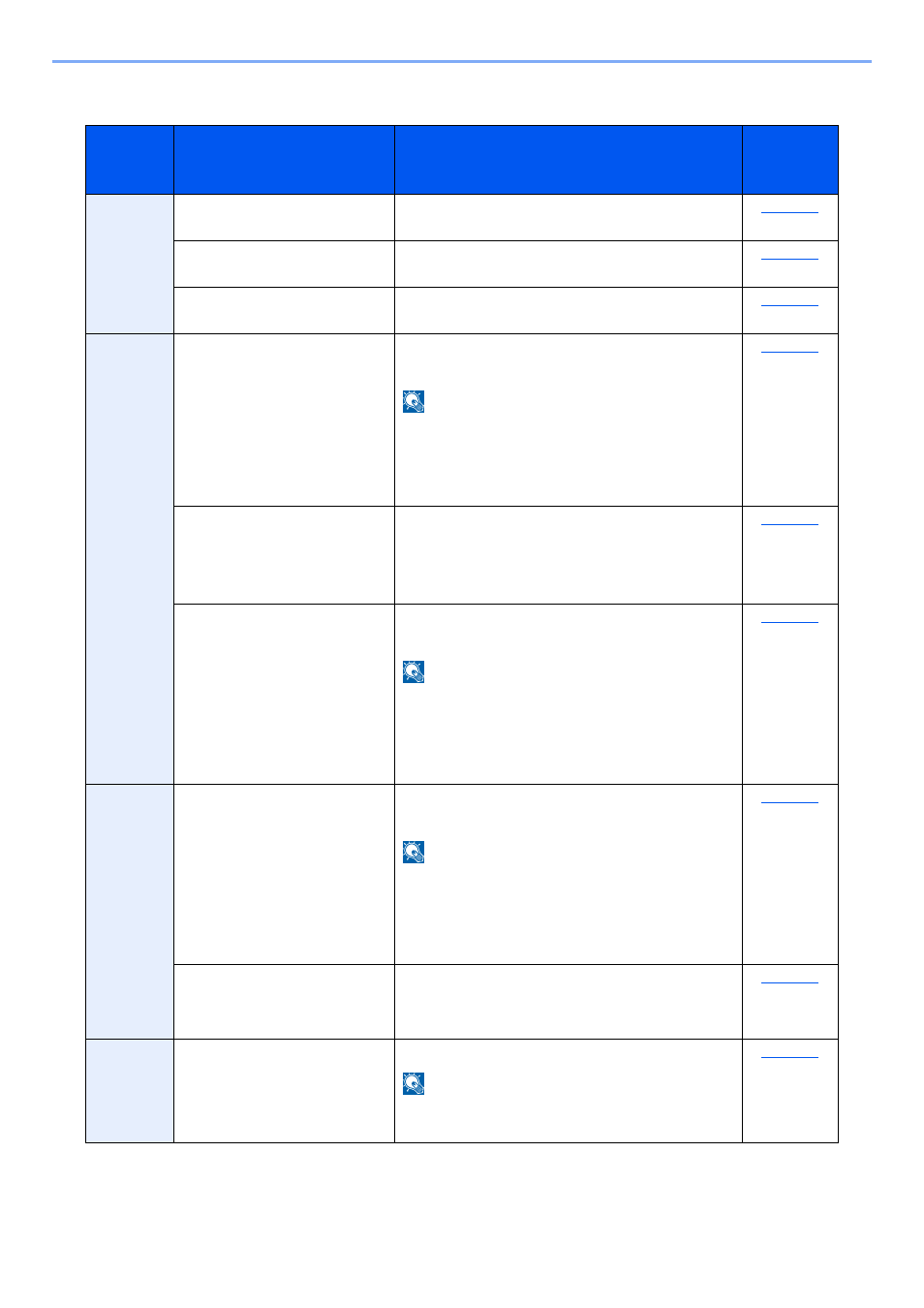
Код ошибки:4701,
5101, 5102, 5103, 5104,
7102, 720f
Выключите и затем включите
главный включатель питания. Если
эта ошибка возникнет повторно,
запишите код ошибки, который
отображается на дисплее
сообщений, и обратитесь к
специалисту по обслуживанию.
(См. процедуру в Сбой аппарата
Вызовите сервисный
персонал.)
Возможно, отсканированы
999 страниц оригиналов?
Если число страниц оригинала
превышает 999, передавайте
страницы отдельными пакетами.
Код ошибки при сканировании с отправкой по Email
Возможно, неправильное
имя сервера SMTP/POP3?
Установите правильное имя
сервера в COMMAND CENTER.
Возможно, вы указали
недопустимые имя
пользователя или пароль?
Введите правильные имя
пользователя и пароль.
Указали ли вы адрес
адресата?
Укажите адрес адресата.
Включен ли протокол
SMTP?
Включите протокол SMTP в
COMMAND CENTER.
Код ошибки:2101,
2102, 2103, 2201, 2202,
2203
Выбрано ли «Другая
аутентификация», когда
выполняется
аутентификация POP
перед SMTP?
Выберите действующего
пользователя POP3,
отличающегося от «Other».
Является ли указанный
сервер сервером SMTP?
Установите правильное имя
сервера в COMMAND CENTER.
Правильно ли выполнено
подключение к сети?
Убедитесь, что сетевой кабель
правильно подключен.
Убедитесь, что сетевая среда
(сервер, концентратор или другая
сеть LAN) работает правильно.
Не пытаетесь ли вы
передать слишком
большой объем данных?
Измените размер, который можно
передавать, в COMMAND
CENTER.
Источник
Ошибки передачи (1102, 1101, 2101) и соединения (0×1102) на принтерах Kyocera происходят из-за неправильной настройки, сетевых сбоев, неправильного ввода данных авторизации при подключении к папке на удаленном ПК.
Основной способ устранения сбоя – правильная настройка оборудования. Необходимо указать нужные параметры на печатающем устройстве и на компьютере, через который выполняется удаленное сканирование.
Что значит такая ошибка: информация из руководства
Неисправность возникает во время передачи документа в папку на удаленном ПК. Код 1102 или 1103 говорят, что принтер не получил доступ из-за неправильного ввода пары логин-пароль или адреса компьютера.
На устройствах Kyocera в случае такого сбоя отображается сообщение «Login to the host has failed». Также возможно появление надписи «Connection Error».
Когда возникает
На принтерах и МФУ ошибка вылетает в таких ситуациях:
- Работе через SMB или FTP сервер.
- Отправке электронных писем из-за ввода неактуальных username или пароля для сервера SMTP либо POP3.
Возможные причины сбоев
Причиной могут быть следующие факторы:
- Периодическое или постоянное отсутствие доступа к сети.
- Недопустимое число символов в названии устройства, логине, пароле.
- Указаны неполный домен, пользовательское имя.
- Путь к сетевой директории прописан неверно.
Неправильная настройка брандмауэра: наличие задач с более высоким приоритетом.
Правильная настройка
Для устранения неисправности нужно правильно настроить оборудование. Сначала проверьте параметры на компьютере, затем на печатающем устройстве.
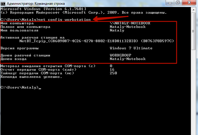
Проверьте, правильно ли указано имя ПК, доменный адрес и username. Для этого введите в командной строке «net config workstation».
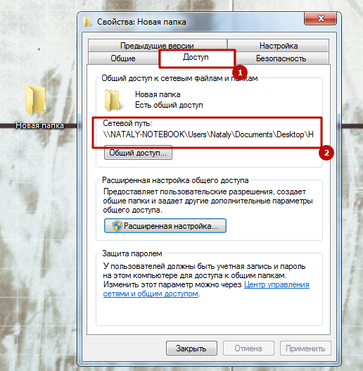
Убедитесь, что правильно указан путь к сетевой папке. Его можно посмотреть в свойствах.
 Windows 7
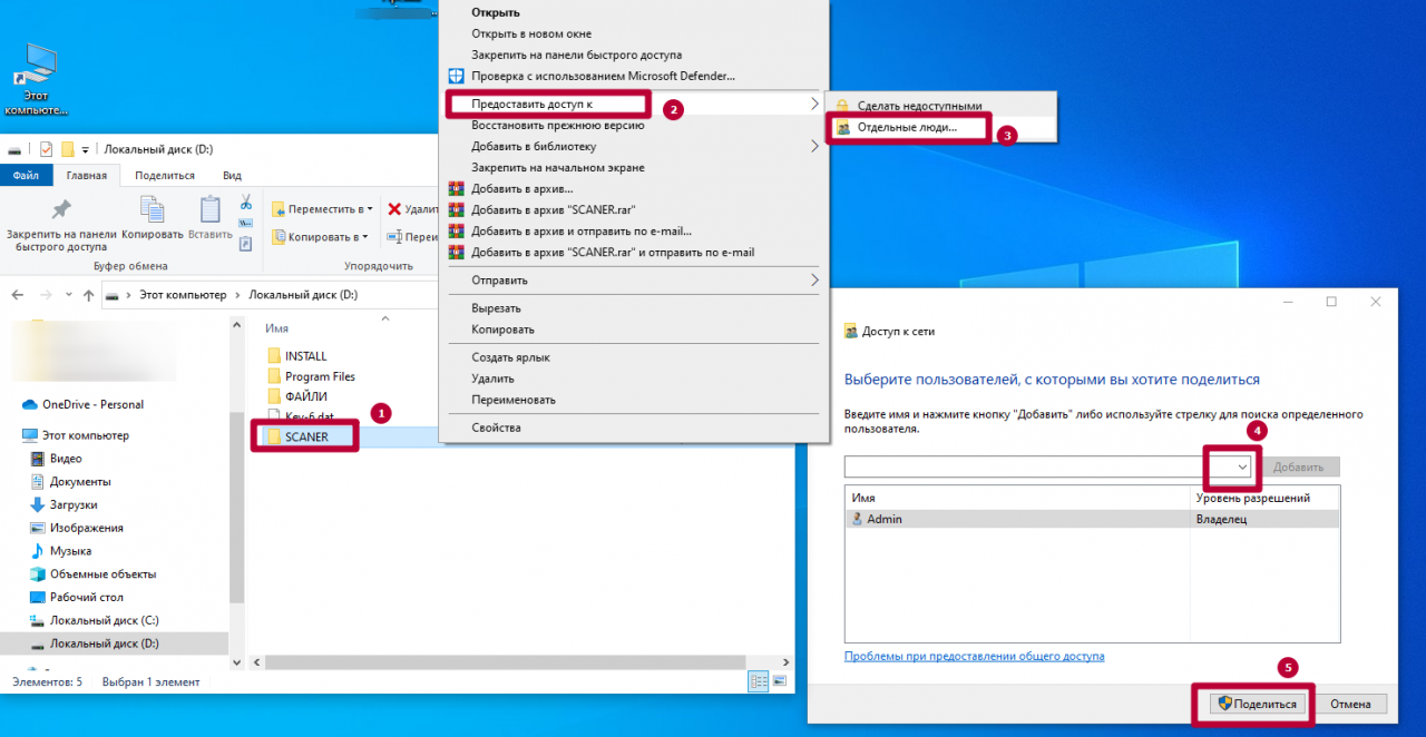 Windows 10
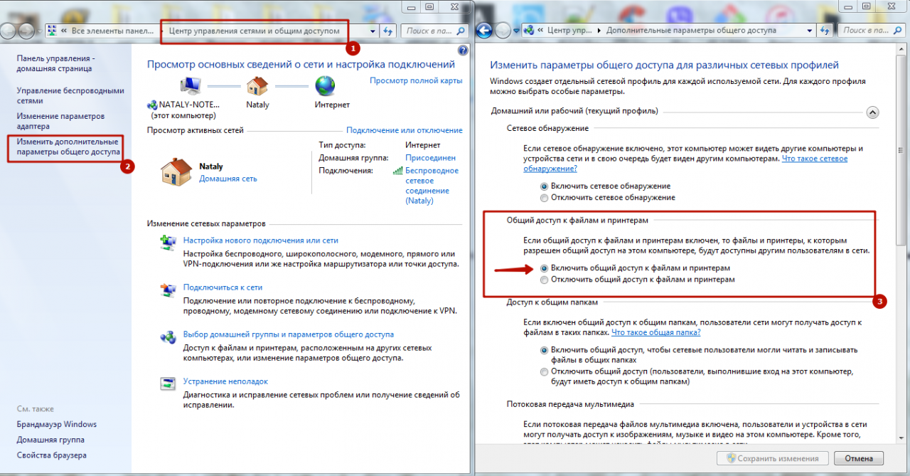
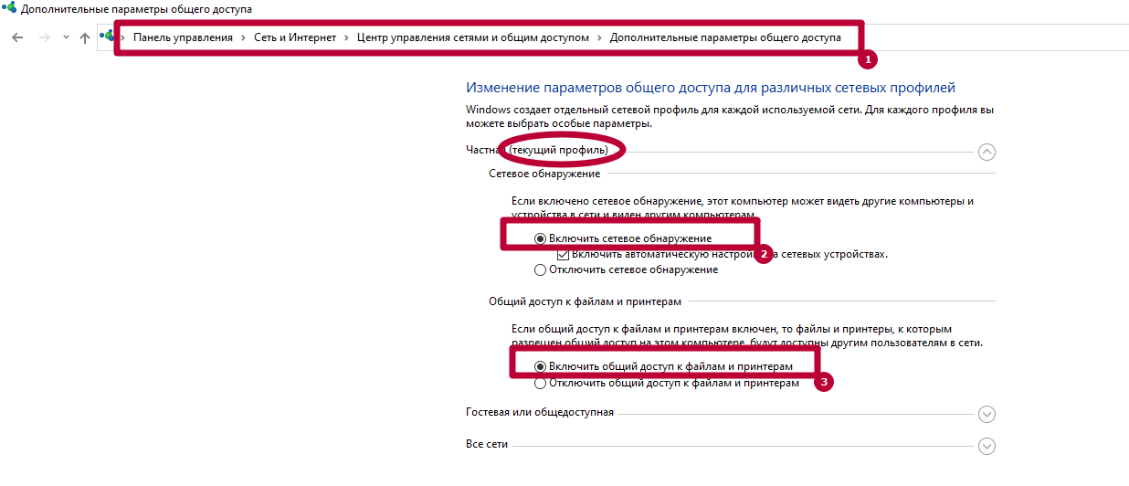
Включите общий доступ для файлов и принтеров. Это можно сделать в «Центре управления сетями», во вкладке «Дополнительные параметры общего доступа».
 Windows 7
 Windows 10
Убедитесь, что на МФУ включены протоколы FTP и SMB. Это можно сделать через интерфейс Command Center. Отправьте оригинал документа, выбрав направление обмена данными.
Укажите имя компьютера и название папки, открытой для общего доступа. Пропишите актуальные данные авторизации для входа на ПК. После проверки подтвердите операцию, нажав «Старт».
Другие ошибки и их решение
На МФУ также могут появиться похожие сбои. Наиболее распространенные – 1103 и 1105.
Появляется при передаче через SMB либо FTP сервер из-за неправильно указанного имени пользователя либо пароля. Также появляется при отсутствии прав доступа к сетевой папке.
Возникает, если в Command Center на Kyocera не включена функция передачи через FTP, SMB или SMTP сервер. В этом случае необходимо задать значение в настройках принтера.
Источник
Устранение ошибки передачи – Инструкция по эксплуатации Kyocera Ecosys m2040dn
Страница 367
Устранение неисправностей > Устранение неисправностей
Устранение ошибки передачи
Меры по устранению
Не удалось отправить
электронную почту.
Проверьте правильность имени хоста SMTP
сервера в Command Center RX.
Не удалось отправить через
FTP.
Проверьте имя хоста FTP.
Не удалось отправить через
SMB.
Проверьте имя хоста SMB.
Не удалось отправить через
SMB.
Проверьте настройки SMB:
•
имя пользователя и пароль при входе.
Если отправитель является пользователем
домена, укажите имя домена:
•
Не удалось отправить
электронную почту.
Проверьте следующее на Command Center RX:
•
имя пользователя и пароль для сервера SMTP;
имя пользователя и пароль для сервера POP3;
предел размера сообщения эл. почты.
Не удалось отправить через
FTP.
Проверьте настройки FTP-сервера:
•
имя пользователя и пароль при входе.
Если отправитель является пользователем
домена, укажите имя домена:
право доступа получателя к папке.
Не удалось отправить через
SMB.
Проверьте настройки SMB:
•
имя пользователя и пароль при входе.
Если отправитель является пользователем
домена, укажите имя домена:
право доступа получателя к папке.
Не удалось отправить через
FTP.
Проверьте настройки FTP-сервера:
•
право доступа получателя к папке.
Не удалось отправить
электронную почту.
Проверьте адрес электронной почты.
Если адрес отклонен доменом, отправка
электронного письма невозможна.
Источник
Kyocera ошибка соединения 0x2101 smtp
Для сканирования и отправки документов по e-mail для МФУ М2835dw необходимо не только наполнить адресную книгу, но и настроить отправку почты по e-mail. Для реализации этой возможности нужно настроить параметры почтовых протоколов, благодаря которым почта будет отправляться на выбранные адреса.
Для настройки отправки почты придется пройтись по меню аппарата, перепрыгивая с одного окна на другое. Над удобством меню, как и над логикой управления инженерам kyocera явно стоит поработать. Перед настройкой необходимо создать пользователя на любом почтовом сервере. В данном случае был создан пользователь Адрес электронной почты защищен от спам-ботов. Для просмотра адреса в вашем браузере должен быть включен Javascript. (на почтовом сервере yandex).
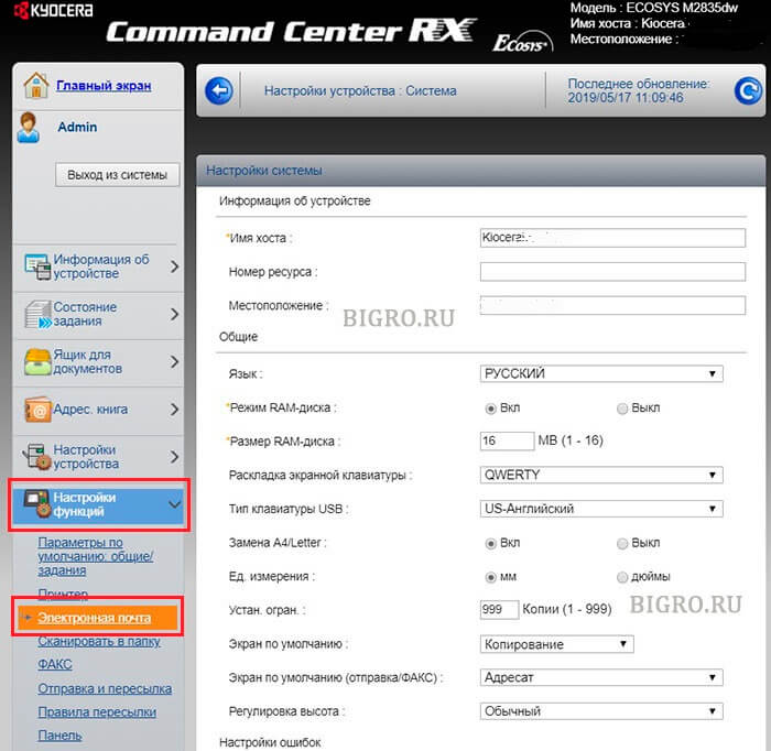
1. Открываем веб-панель МФУ Ecosys Kyocera M2835dw, набираем логин, пароль (по умолчанию Admin — Admin).
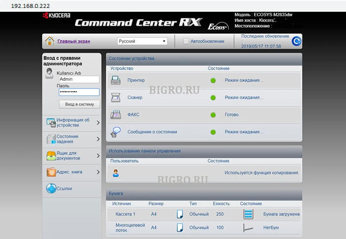
2. Далее переходим «Настройки функций» — «Электронная почта«.
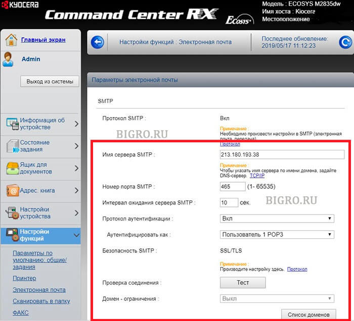
3. В открывшемся окне заполняем:
Имя сервера SMTP: 213.180.193.38
Имя севера SMTP (сервер исходящей почты) зависит от используемого почтового сервера. В данном случае IP-адрес почтового сервера по протоколу smtp 213.180.193.38 (smtp.yandex.ru). Посмотреть настройки основных почтовых серверов можно ЗДЕСЬ.
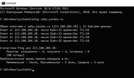
Имя сервера SMTP лучше задать по имени (например, для Yandex — smtp.yandex.ru), но если в сети не работает DNS, то МФУ не будет понимать, что такое smtp.yandex.ru. Проверить можно набрав в командной строке: ping smtp.yandex.ru. Если будет ответ от сервера (пройдут пинги), то можно прописать имя почтового сервера по протоколу smtp, если пинги не пройдут, тогда указываем IP-адрес.
Номер порта smtp: 465.
В данном случае используется шифрование, данный порт используется на почтовом сервере Yandex по протоколу SMTP.
Протокол аутентификации: Вкл.
Аутенфицировать как: Пользователь 1 POP3.
4. В секции «Настройки отправки электронной почты» настраиваем:
Адрес отправителя: Адрес электронной почты защищен от спам-ботов. Для просмотра адреса в вашем браузере должен быть включен Javascript. .
Адрес отправителя — созданный почтовый аккаунт.
Нажимаем «Передать» для сохранения настроек. Далее в секции «POP3» нажимаем кнопку «Параметры» («Настройки пользователя POP3«).
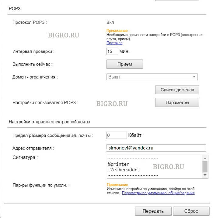
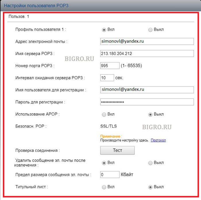
5. В окне «Настройки пользователя POP3«:
Профиль пользователя 1: Вкл.
Адрес электронной почты: Адрес электронной почты защищен от спам-ботов. Для просмотра адреса в вашем браузере должен быть включен Javascript. .
Адрес электронной почты — созданный почтовый аккаунт.
Имя сервера POP3: 213.180.204.212
Имя севера POP3 (сервер входящей почты) зависит от используемого почтового сервера. В данном случае IP-адрес почтового сервера по протоколу pop3 213.180.204.212 (pop.yandex.ru). Посмотреть настройки основных почтовых серверов можно ЗДЕСЬ.
Имя сервера POP3 лучше задать по имени (например, для Yandex — pop.yandex.ru), но если в сети не работает DNS, то МФУ не будет понимать, что такое pop.yandex.ru. Проверить можно набрав в командной строке: ping pop.yandex.ru. Если будет ответ от сервера (пройдут пинги), то можно прописать имя почтового сервера по протоколу POP3, если пинги не пройдут, тогда указываем IP-адрес.
Номер порта POP3: 995.
В данном случае используется шифрование, данный порт используется на почтовом сервере Yandex по протоколу POP3.
Имя пользователя для регистрации Адрес электронной почты защищен от спам-ботов. Для просмотра адреса в вашем браузере должен быть включен Javascript. .
Имя пользователя для регистрации — созданный почтовый аккаунт.
Нажимаем «Передать» для сохранения настроек. Далее нажимаем «Протокол» (Примечание: Произведите настройку здесь).
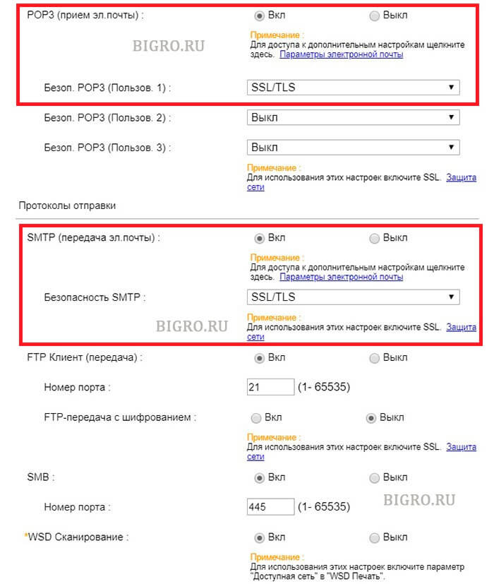
6. В новом окне настраиваем:
POP3 (прием эл. почты): Вкл.
Безоп. POP3 (Пользов. 1): SSL/TLS.
SMTP (передача эл. почты): Вкл.
Безопасность SMTP: SSL/TLS.
Нажимаем «Передать» для сохранения настроек. Далее нажимаем «Защита сети» (Примечание: Для использования этих настроек включите SSL).
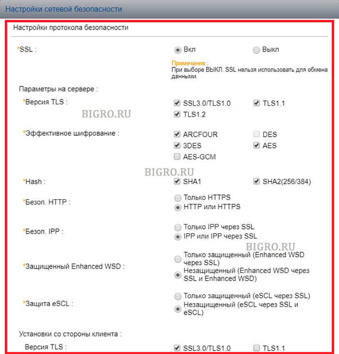
7. В открывшемся окне «Настройки сетевой безопасности» включаем SSL:
SSL: Вкл.
Нажимаем «Передать» для сохранения настроек.
7. Далее переходим в «Настройки электронной почты» (Настройки функций — Электронная почта), в секции SMTP нажимаем кнопку «Тест«. При успешном соединении появится сообщение «Соединение ОК». Это значит, что настройки произведены правильно. Теперь можно сканировать документы и передавать по электронной почте выбранным в адресной книге адресатам.
Источник
Thread: KM-5050 Scan to SMB Error 2101
Thread Tools
Display
KM-5050 Scan to SMB Error 2101
Hello everyone,
I have a KM-5050 with firmware version 2GR_2000.014.028 2007.11.02,
Print works ok.
Trying to hook it up to scan to a folder (via SMB) on Windows Server 2008 R2 Data Center.
Scan to email is also working. I have tried using the hostname and IP address. The username and password is also a domain admin account.
For testing, when hooking it up to an individual laptop, the scan to SMB folder works ok.
Is there any suggestion anyone may know about to get this working?
Is my firmware the culprit?
Thanks in advance for your help.
Claudio
Re: KM-5050 Scan to SMB Error 2101
I remember seeing something like this before. When you put in the username info you need to add the domain info as well. I for the life can’t remember where I saw this but I’ll look around in some stuff I have around and see if I can find it.
update found the info in the Kyocera Scan to SMB(PC) set up guide. check this
Check the information in “domain nameuser name” format for logging onto Windows.
1 Press the Ctrl-Alt-Delete key combination on the
keyboard.
2 Check the Logon Information that appears on the
Windows Security window. In the sample window
below, “ABCDNETjames.smith” corresponds to
“domain nameuser name”.
(Example: ABCDNET james.smith)
Service Manager 1,000+ Posts 

 Join Date Feb 2010 Posts 1,910 Rep Power 71
I think 2101 implies a firewall/anti virus issue
Master Of The Obvious 10,000+ Posts
 Join Date Jul 2007 Location Lapeer, Michigan Posts 21,181 Rep Power 422
Re: KM-5050 Scan to SMB Error 2101
You can get 2101 for a hostname IP issue, or a login/password issue. Either one.
For the sake of diagnosis, I’d suggest creating a new user with a new known password, and new admin properties. Most times it’s login/password related, even if you can log in to the PC/server with this info sometimes it won’t work from the MFP. Many times this has resolved 2101 errors. =^..^=
Re: KM-5050 Scan to SMB Error 2101
Totally agree with this solution, I have a story
Call out to the Customer, 2 local Meath GAA players (Gaelic football) for top tray malfunction on a Kyocera model /Utax 1625. I cleaned the machine located the problem as the try paper size guide was broke etc. I taught I was done, when the Customer told me that the machine won’t print or scan.
I re-installed drivers etc., put in all the scan data and tried to scan ERROR 2101 kept coming up. So out to the car and plugged in the laptop and print and scan function working 100%. I asked the Customer any changes recently and they said the router so I inspect and its fine. I then check the only Pc connected to the machine and give it a good going over. I find the McAfee anti-virus software and disable it and hooray I can print but no scan. I ask the Customer was the anti-virus updated and he said no, shortly after my SM rang because I was there 1.5 hours I explained what happened and he told me to just get going.
I tell the Customer that I must go but would be back with the rtf parts that my SM has been on and that they should have logged the call regarding the print and scan, as I was only into my 2nd year and that call would require a more exp Tech and that if they wanted to print they must either disable or change their settings in the Anti-virus to allow printing. I was not long gone when the Customer called the Office giving out saying I was hopeless etc. and yes my SM called the Customer and asked was the Anti-Virus changed, when he finished that call he gave me the hairdryer treatment. I told him that when I finished the call they wanted me to look at the printing etc., I told him it was the Anti-Virus blocking the printing and he still fumed and sent my Supervisor there. The Supervisor rang me and I told him the story and he came back with a report that the Router was faulty and told the Customer to change it.
It was less than a week and the Customer was raging, the router did not work. The call was logged and the SM sent out his golden boy, the Polish Master who was a lazy git TBH, I have to admit he was there for 3 hours and solved the problem. It was the anti-virus, and yes they had recently got an IT guy in to install it. I was never thanked for attempting the repair but the Customer was charged for the call out and not telling anyone about the change. SUCKER
Источник
В данной статье вы узнаете почему при сетевом сканировании на МФУ Kyocera у вас вылетает ошибка — ошибка соединения. У меня данная ошибка вылезла при очень интересной ситуации, но давайте ее рассмотрим.
Всем привет!
Купили мне тут в конторе небольшое кол-во HDD дисков на 8 терабайт и пару SSD и я решил, что пора обновить всю серверную инфраструктуру до 2019 Server да и вообще пора немного провести ревизию что и как.

Что было сделано:
- Миграция контроллера домена с 2012 на 2019 сервер (если интересно пишите, я сделаю инструкцию)
- Перенос файлового сервера на 2019 сервер с включено технологии ABE
- небольшие мелочи по групповым политикам DNS и DHCP
- Объединение офисов по VPN iPsec с помощью двух микротиков (статья и видео уже тоже скоро выйдут)
В итоге после того как все было сделано и все файловые сервера подняты наступило время настройки сетевых папок для сканирования т.к. у меня парк МФУ очень большое порядка 30 аппаратов я столкнулся с очень странной проблемой, часть парка заработало с пол пинка, а другие никак не хотела настраиваться и вылетала ошибка — ошибка соединения.
Как исправить ошибку на Kyocera — ошибка соединения
Забегая вперед скажу, что данная проблема с которой я столкнулся связана с тем, что принтеры которые никак не хотели сканировать в сетевую папку, были очень старой версии и не могли работать с новыми серверами и это не смотря на то, что я включал smb 1 версии.
Виталий nibbl
После долгих попыток и переборов различных вариантов ситуацию спасла — перепрошивка МФУ Kyocera но новую версию

Подведем итог — если у Вас вылезла ошибка ошибка соединения тут два варианта проблемы:
- Вы не правильно настроили сетевые папки и доступы к ним (читайте статью как правильно настроить сетевое сканирование на Kyocera)
- Обновите прошивку вашего МФУ (читайте статью как правильно перепрошить МФУ Kyocera)
Так что если вы столкнулись с такой ошибкой пиши мне и я Вам отправлю последнюю версию прошивки
Для того чтобы я прислал актуальную версию прошивки пришлите мне:
1) модель МФУ
2) серийный номер
и ждите ответа, я стараюсь отвечать в течении 30 минут.
![]()
nibbl
Я отец двух сыновей, ITишник, предприниматель и просто человек который любит делиться полезной информацией с другими людьми на такие темы как: Windows, Unix, Linux, Web, SEO и многое другое!

Как устранить ошибку 1102 при сетевом сканировании в папку на МФУ Kyocera
Очень часто на некоторых моделях принтеров Kyocera при попытке настроить сканирование в сетевую папку, расположенную на удаленном компьютере, появляется ошибка 1102 или 1103 со словами Login to the host has failed.
Означает это то, что принтер не может подключиться с удаленном папке, в которую настроено сканирование из-за того, что комбинация логин/пароль или имя удаленной машины (host) заданы неверно.
Также это может быть связано с тем, что у пользователя, авторизационные данные которого указаны в настройках принтера, нет прав для доступа к удаленной папке.
В данной статье мы расскажем вам, как можно устранить ошибку 1102/1103 в принтерах Kyocera и настроить опцию сканирования в сетевую папку.
Что нужно сделать и поверить, чтобы устранить ошибку 1102?
Наиболее частыми причинами возникновения ошибки 1102 Login to the host has failed являются:
- Не верно указанные параметры сети, к которой подключен МФУ;
- Ошибочно указанное имя компьютера (хоста), на котором находится сетевая папка;
- Не верные имя пользователи или пароль, с которыми МФУ будет подключаться к удаленной папке. Также у данного пользователя попросту могут отсутствовать права на запись в сетевой папке;
- Не верно указан путь для сканирования.
Стоит отметить, что имя пользователя должно быть указано в настройках аппарата Kyocera в полном виде. То есть с указанием доменного имени – “имя доменаимя пользователя”. А имя папки для сканирования должно быть введено без C:/ и так далее. Только имя папки.
Для полей с именем пользователя и пароля длина вводимых данных не должна превышать 64 символа, а для пути к сетевой папке – 128.
Также рекомендуется создавать сетевую папку без использования пробелов, спец. символов и кириллических букв. Путь к сетевой папке должен быть полностью на английском языке и как можно короче.
Вот здесь вы можете ознакомиться с более подробной инструкцией по настройке сетевого сканирования на МФУ Kyocera.
Лучшая благодарность автору — репост к себе на страничку:

При первичном подключении или вдруг (после установки обновлений безопасности) на уже рабочих настройках сканирования по протоколу SMB могут возникать ошибки, когда, казалось, все сделано по инструкции.
Для начала, прочитайте Настройка МФУ Kyocera для сканирования в сетевую папку и инструкцию пользователя к МФУ, затем проверьте, что настройка прав доступа к папке Windows делалась именно через расширенные настройки:


Убедитесь, что в COMMAND CENTER включен протокол SMB. Значение сетевого пути занесите в настройки соединения, где Host Name — DEMO, а Path — Scanned Documents.
Возможно, вы уже потратили изрядное количество времени на подключение по SMB, и безуспешно. Прежде чем продолжить, подумайте, не будет ли проще просто настроить
- SMTP с отправкой сканированных изображений по электронной почте;
- FTP-сервер в сети и сканирование в папку сервера.
Если вы намерены заставить Kyocera работать с SMB, то продолжим …
К сожалению, в последнее время стало сложно настроить сканирование на компьютер через SMB. Это не вина Kyocera, МФУ этого производителя по-прежнему отлично работают с компьютерами под управлением Windows 7, и проблемы часто возникают из-за «улучшений безопасности». Вина Kyocera в медленной адаптации к изменениям, прошивки выходят с большим опозданием, и пользователи успевают «намучиться» с настройкой сетевых подключений.

Основная проблема часто связана с реализацией SMB в новых операционных системах и обновлениях. Если раньше Windows поддерживала SMB v1, то в новых версиях эта функция отключена. Некоторые принтеры Kyocera поддерживают только SMB v1, другие требуют обновления прошивки для поддержки SMB v2 / v3, а новые устройства поддерживают все три:
МФУ KYOCERA с поддержкой SMB v1/v2/v3
- ECOSYS M2040dn — ECOSYS M4025idn — ECOSYS M4032idn — ECOSYS M8024cidn — ECOSYS M8030cidn
- ECOSYS M2135dn
- ECOSYS M2635dn
- ECOSYS M2735dw — ECOSYS M2540dn — ECOSYS M2640idw —
- ECOSYS M5521cdn — ECOSYS M5521cdw — ECOSYS M5526cdn — ECOSYS M5526cdw
- TASKalfa 3211i — TASKalfa 4011i
- TASKalfa 5052ci — TASKalfa 4052ci. TASKalfa 6052ci
- TASKalfa 2552ci — TASKalfa 3252ci
- TASKalfa 4002i — TASKalfa 5002i — TASKalfa 6002i — TASKalfa 7002i — TASKalfa 8002i
- TASKalfa 7052ci — TASKalfa 8052ci
требуется обновление прошивки до 6 версии и выше
- ECOSYS M6030cdn — ECOSYS M6530cdn — ECOSYS M6035cidn — ECOSYS M6535cidn
- TASKalfa 3051ci
- TASKalfa 3501i — TASKalfa 4501i — TASKalfa 5501i — TASKalfa 6501i
- TASKalfa 3551ci — TASKalfa 4551ci — TASKalfa 5551ci
- TASKalfa 6551ci — TASKalfa 7551ci
- TASKalfa 6551ci — TASKalfa 7551ci
требуется обновление прошивки до 3 версии и выше
- TASKalfa 306ci — TASKalfa 356ci — TASKalfa 406ci
требуется обновление прошивки до 5 версии и выше
- ECOSYS M3040dn — ECOSYS M3540dn — ECOSYS M3040idn — ECOSYS M3540idn — ECOSYS M3550idn — ECOSYS M3560idn — ECOSYS M6026cdn — ECOSYS M6526cdn — ECOSYS M6026cidn — ECOSYS M6526cidn — ECOSYS M2030dn — ECOSYS M2530dn — ECOSYS M2035dn — ECOSYS M2535dn
- TASKalfa 266ci
- TASKalfa 3010i — TASKalfa 3510i
- TASKalfa 2551ci
МФУ KYOCERA с поддержкой SMB v1
- TASKalfa 3050ci — TASKalfa 3550ci — TASKalfa 4550ci — TASKalfa 5550ci
- TASKalfa 1800 — TASKalfa 2200
- FS-1220MFP — FS-1320MFP — FS-1325MFP — FS-6025MFP — FS-6030MFP — FS-6525MFP — FS-6530MFP — FS-C8020MFP — FS-C8025MFP — FS-C8520MFP — FS-C8525MFP
Проверьте текущую версию прошивки в Информации об устройстве и обновите МФУ при необходимости.
Если ваше оборудование не поддерживает современные версии протокола, то можно (но крайне не рекомендуется с точки зрения сетевой безопасности) включить поддержку SMB v1 в операционной системе. Это можно сделать временно, в качестве одного из шагов поиска причины ошибки соединения, как и временное отключение Брандмауэра и Антивируса.
Если перепробовали «уже все»…, а соединение все еще не настроено, проверьте следующее:
- IP-адрес машины вместо имени хоста.
- Исключения в брандмауэре Windows (входящие, принтеры и общий доступ к файлам, SMB)
- Включите общий доступ к папке
- Проверьте сетевой профиль сети, к которой вы подключены, и установите для него частный
- Установите флажок «Разрешить общий доступ к файлам для устройств, использующих 40- или 56-битное шифрование» в «Расширенных настройках общего доступа», также включите «Совместное использование, защищенное паролем».
Установите для этих служб значение «Автоматически»:
- Хост поставщика обнаружения функций
- Публикация ресурсов для обнаружения функций
- Обнаружение SSDP
- Хост устройства UPnP
Рекомендуем ознакомиться с полным списком наших статей на Яндекс Дзене. Мы будем признательны, если вы оставите в комментариях к статье ваш удачный или неудачный опыт решения данного вопроса. Значимая информация будет добавлена в публикацию.
Тэги: network, диагностика, МФУ, эксплуатация,
При первичном подключении или вдруг (после установки обновлений безопасности) на уже рабочих настройках сканирования по протоколу SMB могут возникать ошибки, когда, казалось, все сделано по инструкции.
Для начала, прочитайте Настройка МФУ Kyocera для сканирования в сетевую папку и инструкцию пользователя к МФУ, затем проверьте, что настройка прав доступа к папке Windows делалась именно через расширенные настройки:
Убедитесь, что в COMMAND CENTER включен протокол SMB. Значение сетевого пути занесите в настройки соединения, где Host Name — DEMO, а Path — Scanned Documents.
Возможно, вы уже потратили изрядное количество времени на подключение по SMB, и безуспешно. Прежде чем продолжить, подумайте, не будет ли проще просто настроить
- SMTP с отправкой сканированных изображений по электронной почте;
- FTP-сервер в сети и сканирование в папку сервера.
Если вы намерены заставить Kyocera работать с SMB, то продолжим …
К сожалению, в последнее время стало сложно настроить сканирование на компьютер через SMB. Это не вина Kyocera, МФУ этого производителя по-прежнему отлично работают с компьютерами под управлением Windows 7, и проблемы часто возникают из-за «улучшений безопасности». Вина Kyocera в медленной адаптации к изменениям, прошивки выходят с большим опозданием, и пользователи успевают «намучиться» с настройкой сетевых подключений.
Основная проблема часто связана с реализацией SMB в новых операционных системах и обновлениях. Если раньше Windows поддерживала SMB v1, то в новых версиях эта функция отключена. Некоторые принтеры Kyocera поддерживают только SMB v1, другие требуют обновления прошивки для поддержки SMB v2 / v3, а новые устройства поддерживают все три:
МФУ KYOCERA с поддержкой SMB v1/v2/v3
- ECOSYS M2040dn — ECOSYS M4025idn — ECOSYS M4032idn — ECOSYS M8024cidn — ECOSYS M8030cidn
- ECOSYS M2135dn
- ECOSYS M2635dn
- ECOSYS M2735dw — ECOSYS M2540dn — ECOSYS M2640idw —
- ECOSYS M5521cdn — ECOSYS M5521cdw — ECOSYS M5526cdn — ECOSYS M5526cdw
- TASKalfa 3211i — TASKalfa 4011i
- TASKalfa 5052ci — TASKalfa 4052ci. TASKalfa 6052ci
- TASKalfa 2552ci — TASKalfa 3252ci
- TASKalfa 4002i — TASKalfa 5002i — TASKalfa 6002i — TASKalfa 7002i — TASKalfa 8002i
- TASKalfa 7052ci — TASKalfa 8052ci
требуется обновление прошивки до 6 версии и выше
- ECOSYS M6030cdn — ECOSYS M6530cdn — ECOSYS M6035cidn — ECOSYS M6535cidn
- TASKalfa 3051ci
- TASKalfa 3501i — TASKalfa 4501i — TASKalfa 5501i — TASKalfa 6501i
- TASKalfa 3551ci — TASKalfa 4551ci — TASKalfa 5551ci
- TASKalfa 6551ci — TASKalfa 7551ci
- TASKalfa 6551ci — TASKalfa 7551ci
требуется обновление прошивки до 3 версии и выше
- TASKalfa 306ci — TASKalfa 356ci — TASKalfa 406ci
требуется обновление прошивки до 5 версии и выше
- ECOSYS M3040dn — ECOSYS M3540dn — ECOSYS M3040idn — ECOSYS M3540idn — ECOSYS M3550idn — ECOSYS M3560idn — ECOSYS M6026cdn — ECOSYS M6526cdn — ECOSYS M6026cidn — ECOSYS M6526cidn — ECOSYS M2030dn — ECOSYS M2530dn — ECOSYS M2035dn — ECOSYS M2535dn
- TASKalfa 266ci
- TASKalfa 3010i — TASKalfa 3510i
- TASKalfa 2551ci
- TASKalfa 3050ci — TASKalfa 3550ci — TASKalfa 4550ci — TASKalfa 5550ci
- TASKalfa 1800 — TASKalfa 2200
- FS-1220MFP — FS-1320MFP — FS-1325MFP — FS-6025MFP — FS-6030MFP — FS-6525MFP — FS-6530MFP — FS-C8020MFP — FS-C8025MFP — FS-C8520MFP — FS-C8525MFP
Проверьте текущую версию прошивки в Информации об устройстве и обновите МФУ при необходимости.
Если ваше оборудование не поддерживает современные версии протокола, то можно (но крайне не рекомендуется с точки зрения сетевой безопасности) включить поддержку SMB v1 в операционной системе. Это можно сделать временно, в качестве одного из шагов поиска причины ошибки соединения, как и временное отключение Брандмауэра и Антивируса.
Если перепробовали «уже все»…, а соединение все еще не настроено, проверьте следующее:
- IP-адрес машины вместо имени хоста.
- Исключения в брандмауэре Windows (входящие, принтеры и общий доступ к файлам, SMB)
- Включите общий доступ к папке
- Проверьте сетевой профиль сети, к которой вы подключены, и установите для него частный
- Установите флажок «Разрешить общий доступ к файлам для устройств, использующих 40- или 56-битное шифрование» в «Расширенных настройках общего доступа», также включите «Совместное использование, защищенное паролем».
Установите для этих служб значение «Автоматически»:
- Хост поставщика обнаружения функций
- Публикация ресурсов для обнаружения функций
- Обнаружение SSDP
- Хост устройства UPnP
Рекомендуем ознакомиться с полным списком наших статей на Яндекс Дзене. Мы будем признательны, если вы оставите в комментариях к статье ваш удачный или неудачный опыт решения данного вопроса. Значимая информация будет добавлена в публикацию.
Тэги: network, диагностика, МФУ, эксплуатация,
Содержание
- Kyocera smb ошибка соединения windows 10
- Ошибка при сканировании в сетевую папку.
- Повторная проверка компьютеров с ошибкой при сканировании в сетевую папку
- Временное решении ошибки при сканировании в сетевую папку
- Планирование для дальнейшей работоспособности сканировании в сетевую папку с экрана МФУ
- Описание обновления которое делит SMBv1 на серверную и клиентскую часть.
- kyocera не сканирует в сетевую папку
- Настройка сканирования в папку
- Настройка smb kyocera windows 10
- Вопрос
- Ответы
- Все ответы
- Настройка мфу Kyocera для сканирования в сетевую папку. Часто встречающиеся ошибки и способы их устранения.
Kyocera smb ошибка соединения windows 10

Ошибка при сканировании в сетевую папку.
Спустя некоторое время у пользователей начали появляться ошибки при сканировании документов с МФУ HP LaserJet m521dn Pro.

Ошибка при сканировании, проявлялась на мониторе МФУ в момент установки соединения с компьютером где размещалась настроенная сетевая папка. В веб интерфейсе МФУ при запуске теста также выдавалась ошибка.

У большей части пользователей при сканировании с этой модели МФУ ошибка не проявлялась.
Наступил день, когда мне пришлось сканировать документ к себе на компьютер и тут ошибка добралась до меня с моим компьютером. Это ошибка проявилась именно так как и на всех тех компьютерах где она была.
Повторная проверка компьютеров с ошибкой при сканировании в сетевую папку
Я много всего проверил:
Все это указывала на скрытую настройку или изменение в моем компьютере.
Я попытал свое счастье на МФУ от производителя Konica Minolta (использует протокол SMBv1, SMBv2, SMBv3) и нужный мне документ на этом устройстве отсканировался и был отправлен в сетевую папку на моем компьютере. Это очень сильно меня запутало в тот момент с проблемой только на компьютере.
Подобная ошибка соединения уже встречалась и связана она была с отключением протокола SMBv1, после обновления от Microsoft. Цель обновления заключалась в предотвращения заражения компьютера вирусом на подобие WannaCry, использующий протокол SMBv1.
Я еще раз все проверил на всех не работающих компьютерах где не работало сканирование, на наличие включенного протокола SMBv1
Как узнать включенвыключен SMBv1 с помощью PowerShell:
Тут меня смутили новые строки в «ServerComponent» ранее я не припоминал такого параметра.
Первым делом я отправился смотреть «Включение или отключение компонентов Windows» на своем компьютере где не работало сканирование:

SMB теперь делится и у него отключен компонент «Сервер SMB».
После увиденного я отправился смотреть компоненты на тот компьютер где работало сканирование с этой модели МФУ HP LaserJet:

Временное решении ошибки при сканировании в сетевую папку
ВОТ эта проблема. После включения компонента «сервер SMBv1» Сканирование с МФУ HP LaserJet m521dn PRO на мой компьютер было восстановлено.
На этом конечно мне нельзя было останавливаться, так как рано или поздно это обновление доберется до других компьютеров и закроет сетевой доступ для сохранения отсканированных документов к себе на компьютеры.
Планирование для дальнейшей работоспособности сканировании в сетевую папку с экрана МФУ
Здесь сразу видно несколько решений:
Один из этих вариантов рассмотрим в следующей статье.
Описание обновления которое делит SMBv1 на серверную и клиентскую часть.
Здесь расписано подробно об изменениях в протоколе SMBv1 ссылка
Краткий основной перечень изменений:
В данном блоге нас чутли не заставляют не использовать протокол 1 версии, тем временем у HP совсем другой взгляд на этот протокол со своими устройствами. Ссылка https://blogs.technet.microsoft.com/filecab/2016/09/16/stop-using-smb1/
SMB1 isn’t good Stop using SMB1. For your children. For your children’s children. Please. We’re begging you. And if that’s not enough: SMB1 is being removed (fully or partially, depending on SKU) by default in the RS3 release of Windows and Windows Server. This is here folks: https://aka.ms/smb1rs3
Источник
kyocera не сканирует в сетевую папку

Настройки сетевого сканирования полностью идентичны для всех моделей KYOCERA ECOSYS M2040dn / M2540dn / M2035dn / M2535dn
На самом деле всё довольно-таки просто!
Предполагается, что аппарат уже настроен, и работает как принтер, и автоматически получил все сетевые настройки через DHCP.
Для начала заходим на WEB-страничку аппарата по его IP адресу через браузер.
Необходимо авторизоваться. Логин Admin, пароль тоже Admin. Обратите внимание, буквы A заглавные!
Вот в этом окошке как раз все основные записи. О них поподробнее.
Сканирование возможно по трём направлениям:
1. Электронная почта
2. SMB (сетевая папка)
3. FTP (папка на FTP-сервере)
Можно прописать все три канала, как в нашем примере, или выбрать что-то одно, в зависимости от потребностей.
Номер: — произвольное число.
Имя: — то, что будет показано на экране МФУ.
Электронная почта
Адрес электронной почты: — сюда вписываем адрес получателя скана.
Для отправки на почту на этой страничке больше ничего не требуется. Есть ещё настройки отправителя, но о них чуть позже.

На этой страничке необходимо настроить отправителя почты.
Для этого вам потребуется какой-либо почтовый ящик, от имени которого аппарат будет слать почту.
В нашем примере мы использовали gmail.com и адрес на нём dos.jp@argusmaster.ru
Просто заполните все поля аналогично примеру, используя данные вашего почтового сервера.
Надеемся, что эта статья была Вам полезной.
!! Если Вам необходимо настроить сетевое сканирование через TWAIN драйвер с помощью компютера, подробную инструкцию можно прочитать по этой ссылке.
Kyocera FS-6525MFP это очень хорошее многофункциональное устройство (МФУ) с максимальным форматом А3. Как правило такие аппараты используют несколько сотрудников или целый офис если он не большой. Для удобства можно настроить сканирование в сетевую папку. Давайте рассмотрим, как это можно сделать на примере Kyocera FS-6525MFP, данная инструкция подойдет и для других моделей.
Самые популярные статьи по теме.
Настройка сканирования в папку
Настроить сканирование в сетевую папку можно двумя способами с самого аппарата или по сети. Второй вариант намного удобней по этому будем использовать именно его. Первое что вам нужно сделать это узнать IP адрес вашего устройства. Его можно распечатать с самого МФУ если зайти в настройки. Дальше открываем браузер и вводим IP. После чего откроется домашняя страница.

Для начала нужно проверить включен ли необходимый протокол. Для этого нужно ввести логина пароль администратора по умолчанию для этого устройства это Admin Admin.

Дальше открываем Параметры.

Переходим на вкладку «Сканер» и слева в списке выбираем пункт «SMB». Проверяем включен ли данный сетевой протокол и указан ли порт. Если все включено то переходим обратно кликаем «Домашняя страница».

Слева выбираем «Адресная книга» И жмем добавить контакт.

Вводим номер контакта, дальше указываем имя. Теперь в блоке «SMB» указываем имя хоста (IP адрес компьютера где расположена сетевая папка). Порт оставляем по умолчанию. В поле путь указываем название расшаренной папки. Дальше вводим имя пользователя и пароль и запускаем проверку соединения.

Если вы все ввели правильно то должны увидеть сообщение.

Теперь идем к устройству и пробуем сканировать в сетевую папку. Для этого нужно на устройстве нажать «Отправить» дальше зайти в «Контакты» выбрать созданный контакт и нажать Старт.
Рассмотрим настройку сетевого сканирования в папку на примере Kyocera fs-1035mfp.
Теперь необходимо проверить сетевое сканирование в папку:
1) На аппарате Kyocera нажимаем клавишу «Отправить(электронная почта/папка)»
2) Затем нажимаем клавишу «Адресная книга».
3) Выбираем созданную запись и нажимаем 2(два) раза клавишу «OK»
4) После появления надписи «Готов к передаче» нажимаем клавишу «Старт»
5) Если все настройки были выполнены верно — то в указанной папке для сканирования появится отсканированный документ.
Источник
Настройка smb kyocera windows 10

Вопрос
Ответы
У меня аппараты куасера при указании пути и пользователя рядом есть кнопка тестировать. Нажимаешь и сразу проверяешь имеются права доступа или нет.
Добавьте пользователя на машину с Win 10 под которым производите сканирование.
Отключите брандмауер и защитник. Если проблема после этого устранена значит ищите проблему в нем. Антивирус какой? У меня на доктор вебе стоит ограничение в офисном контроле на сканеры и прочее оборудование.
Папку как расшаривали? Только общий доступ?
Добавьте пользователя под которым происходит сканирование во вкладке общий доступ и поставьте права совладельца и во вкладке безопасность и проставьте (все) галочки.
Все ответы
Воткнуть его в сеть и повторить попытку сканирования на сетевую шару не пробовали?
Я не волшебник, я только учусь MCP CCNA. Если Вам помог чей-либо ответ, пожалуйста, не забывайте жать на кнопку «Пометить как ответ» или проголосовать «полезное сообщение». Мнения, высказанные здесь, являются отражением моих личных взглядов, а не позиции работодателя. Вся информация предоставляется как есть без каких-либо гарантий. Блог IT Инженера, Twitter, YouTube, GitHub.
Проверьте, что на ПК с Windows 10 включен протокол SMB 1 и попробуйте отсканировать.
Как проверить, включить/выключить SMB:
Добрый день. Возникла проблема с сетевым сканированием на пк в папку с общим доступом. МФУ Kyocera fs-6525. на пк с win 7 сканирование идет без проблем. с 10кой сканер выдает ошибку. к папке доступ точно есть на запись и чтение. Помогите с данным вопросом
У меня аппараты куасера при указании пути и пользователя рядом есть кнопка тестировать. Нажимаешь и сразу проверяешь имеются права доступа или нет.
Добавьте пользователя на машину с Win 10 под которым производите сканирование.
Отключите брандмауер и защитник. Если проблема после этого устранена значит ищите проблему в нем. Антивирус какой? У меня на доктор вебе стоит ограничение в офисном контроле на сканеры и прочее оборудование.
Папку как расшаривали? Только общий доступ?
Добавьте пользователя под которым происходит сканирование во вкладке общий доступ и поставьте права совладельца и во вкладке безопасность и проставьте (все) галочки.
Уважаемый RomanLRV, данная тема имеет решение и не Актуальна.
Не стоит заниматься некропостингом.
Надеюсь на понимание
Я не волшебник, я только учусь MCP, CCNA. Если Вам помог чей-либо ответ, пожалуйста, не забывайте нажать на кнопку «Пометить как ответ» или проголосовать за полезное сообщение. Мнения, высказанные здесь, являются отражением моих личных взглядов, а не позиции работодателя. Вся информация предоставляется как есть без каких-либо гарантий. Блог IT Инженера, Twitter, YouTube, GitHub, Instagram
Во-первых: Проблема не решена! Имеем лицензионное г-но windows 10 сборки 1909, smb 100500% включено, как и автор первоначального проблемы здесь, я много киосер вводил в эксплуатацию и всегда без проблем, особенно на win 7 (если исключить ввод киосер на домашние сборки, когда искусственно скидываются задания из планировщика при обновлениях на скрипт переустановки нуджного для киосеры пароля для киосеровского пользователя)
Во-вторых: Уважаемый модератор! Понятно что у Вас бомбанет я буду отправлен в бан а сообщение вскоре пропадет из поста, но потрудитесь в будуще пошевелить Вашей могучей 5-й точкой опубликовать несложную конструкцию: Решение: и цитата на решение, перед закрытием темы с очень умным видом, хотя выглядите Вы при этом крайне глупо и напыщено и ничего такими комментариями положительного у людей не вызываете. Не стоит заниматься некропостингом. Не стоит использовать мелкомягкий некрософт.
Пока не словил бан, и надеюсь Модератор хоть от своего имени перепубликует РЕАЛЬНОЕ РЕШЕНИЕ:
1. CMD от имени администратора
3. Остальные настройки как на windows 7 и работаем с поддержкой kyoera, если не получается
Источник
Настройка мфу Kyocera для сканирования в сетевую папку. Часто встречающиеся ошибки и способы их устранения.

Предварительно следует настроить папку для получения документов на компьютере:
1. Проверьте сетевые «Полное имя» компьютера ( Хост ), домен и имя пользователя и запишите значения. Пользователи Windows в командной строке могут набрать » net config workstation «, либо получить нужные значения через Свойство компьютера.
2. Создайте сетевую папку и настройте права доступа в ней. В общей папке можно создать подпапку в качестве расположения для передачи данных. В этом случае в поле Путь нужно ввести » имя общей папкиимя подпапки «.
После этого можно переходить к настройке МФУ:
1. Убедитесь, что в COMMAND CENTER включены протоколы SMB и FTP (подробная информация изложена в руководстве пользователя, в том числе правило ввода символов).
5. Введите имя папки, заданное в параметрах общего доступа.
6. Введите имя и пароль пользователя, которые используются для входа в компьютер с папкой общего доступа.

При внесении неправильных данных могут возникать ошибки с кодами 1102, 1103 и 3101 при проблемах с FTP сервером.
Причины сбоев и ошибок:
1. Постоянная или временная недоступность настроенного сетевого ресурса.
3. Ошибка 1102 может возникать при использовании короткого логина вместо полного » имя доменаимя пользователя «.
4. Неверный путь к сетевой папке, например указан локальный путь, а не сетевой.
5. Если все сохраненные значения параметров верны, а при попытке сканирования возникает ошибка, проверьте настройки Сетевого экрана (Брандмауэра), возможно в сетевых правилах существует запись с более высоким приоритетом, блокирующая порт.
Источник
Настройки сетевого сканирования полностью идентичны для всех моделей KYOCERA ECOSYS M2040dn / M2540dn / M2035dn / M2535dn
На самом деле всё довольно-таки просто!
Предполагается, что аппарат уже настроен, и работает как принтер, и автоматически получил все сетевые настройки через DHCP.
Для начала заходим на WEB-страничку аппарата по его IP адресу через браузер.
Необходимо авторизоваться. Логин Admin, пароль тоже Admin. Обратите внимание, буквы A заглавные!
Вот в этом окошке как раз все основные записи. О них поподробнее.
Сканирование возможно по трём направлениям:
1. Электронная почта
2. SMB (сетевая папка)
3. FTP (папка на FTP-сервере)
Можно прописать все три канала, как в нашем примере, или выбрать что-то одно, в зависимости от потребностей.
На этой страничке необходимо настроить отправителя почты.
Для этого вам потребуется какой-либо почтовый ящик, от имени которого аппарат будет слать почту.
В нашем примере мы использовали gmail.com и адрес на нём dos.jp@argusmaster.ru
Просто заполните все поля аналогично примеру, используя данные вашего почтового сервера.
Надеемся, что эта статья была Вам полезной.
!! Если Вам необходимо настроить сетевое сканирование через TWAIN драйвер с помощью компютера, подробную инструкцию можно прочитать по этой ссылке.
Источник
Ошибка при сканировании в сетевую папку.
Спустя некоторое время у пользователей начали появляться ошибки при сканировании документов с МФУ HP LaserJet m521dn Pro.
Ошибка при сканировании, проявлялась на мониторе МФУ в момент установки соединения с компьютером где размещалась настроенная сетевая папка. В веб интерфейсе МФУ при запуске теста также выдавалась ошибка.
У большей части пользователей при сканировании с этой модели МФУ ошибка не проявлялась.
Наступил день, когда мне пришлось сканировать документ к себе на компьютер и тут ошибка добралась до меня с моим компьютером. Это ошибка проявилась именно так как и на всех тех компьютерах где она была.
Повторная проверка компьютеров с ошибкой при сканировании в сетевую папку
Я много всего проверил:
- МФУ HP LaserJet m521dn PRO использует SMBv1, ниже указан пример проверки работоспособности протокола этой версии
- Права доступа к сетевой папке
- Менял учетную запись для авторизации на сетевом ресурсе, менял пароль
- Пытался сканировать с другой МФУ этой же модели на тотже адрес
Все это указывала на скрытую настройку или изменение в моем компьютере.
Я попытал свое счастье на МФУ от производителя Konica Minolta (использует протокол SMBv1, SMBv2, SMBv3) и нужный мне документ на этом устройстве отсканировался и был отправлен в сетевую папку на моем компьютере. Это очень сильно меня запутало в тот момент с проблемой только на компьютере.
Подобная ошибка соединения уже встречалась и связана она была с отключением протокола SMBv1, после обновления от Microsoft. Цель обновления заключалась в предотвращения заражения компьютера вирусом на подобие WannaCry, использующий протокол SMBv1.
Я еще раз все проверил на всех не работающих компьютерах где не работало сканирование, на наличие включенного протокола SMBv1
Как узнать включенвыключен SMBv1 с помощью PowerShell:
Тут меня смутили новые строки в «ServerComponent» ранее я не припоминал такого параметра.
Первым делом я отправился смотреть «Включение или отключение компонентов Windows» на своем компьютере где не работало сканирование:
SMB теперь делится и у него отключен компонент «Сервер SMB».
После увиденного я отправился смотреть компоненты на тот компьютер где работало сканирование с этой модели МФУ HP LaserJet:
Временное решении ошибки при сканировании в сетевую папку
ВОТ эта проблема!!! После включения компонента «сервер SMBv1» Сканирование с МФУ HP LaserJet m521dn PRO на мой компьютер было восстановлено.
На этом конечно мне нельзя было останавливаться, так как рано или поздно это обновление доберется до других компьютеров и закроет сетевой доступ для сохранения отсканированных документов к себе на компьютеры.
Планирование для дальнейшей работоспособности сканировании в сетевую папку с экрана МФУ
Здесь сразу видно несколько решений:
- Выкинуть эти МФУ (дата выпуска 2014 год, эксплуатация с 2017) которые в 2018 году поддерживают только SMBv1 (дата рождения протокола в 1990г.). В этом документе SMB Protocol Support for HP Printing Devices вы можете ознакомиться с моделями МФУ, которые используют только SMBv1 и какие используют SMBv2 и SMBv3. Список устройств использующих SMBv1 очень велик.
- Настроить всем личные сетевые папки на старом файловом сервере и настроить сканирование в эти каталоги.
- Пренебрегать безопасности и включить всем «сервер SMBv1» в компонентах групповыми политиками
Один из этих вариантов рассмотрим в следующей статье.
Описание обновления которое делит SMBv1 на серверную и клиентскую часть.
Здесь расписано подробно об изменениях в протоколе SMBv1 ссылка
Краткий основной перечень изменений:
- SMBv1 теперь имеет клиентские и серверные подфункции, которые могут удаляться отдельно.
- Версии Windows 10 Enterprise и Windows 10 Education по умолчанию больше не включают клиент или сервер SMBv1 после чистой установки.
- Версия Windows Server 2016 по умолчанию больше не включает клиент или сервер SMBv1 после чистой установки.
- Версии Windows 10 Home и Windows 10 Professional по умолчанию больше не включают сервер SMBv1 после чистой установки.
- Версии Windows 10 Home и Windows 10 Professional по умолчанию все еще включают клиент SMBv1 после чистой установки. Если клиент SMBv1 не используется в целом 15 дней (за исключением времени, когда компьютер выключен), он автоматически удаляется самостоятельно.
- Локальные обновления и запуски Insider Windows 10 Home и Windows 10 Professional сначала не удаляют автоматически SMB1. Если клиент или сервер SMBv1 не используются в целом 15 дней (за исключением времени, когда компьютер выключен), они автоматически удаляются самостоятельно.
- Локальные обновления и запуски Insider Windows 10 Enterprise и Windows 10 Education не удаляют SMB1. Администратор может решить удалить SMB1 в этих управляемых окружениях.
- Автоматическое удаление SMB1 спустя 15 дней — это одноразовая операция. Если администратор повторно устанавливает SMB1, система больше не пытается удалить его.
- Функции SMB версии 2.02, 2.1, 3.0, 3.02 и 3.1.1 все еще полностью поддерживаются и включаются по умолчанию в составе двоичных файлов SMBv2.
- Так как служба браузера компьютеров использует протокол SMBv1, служба удаляется, если удаляется клиент или сервер SMBv1. Это означает, что Сетевой проводник больше не может отображать компьютеры Windows с помощью устаревшего метода просмотра датаграммы NetBIOS.
- SMBv1 все еще можно повторно установить во всех версиях Windows 10 и Windows Server 2016.
В данном блоге нас чутли не заставляют не использовать протокол 1 версии, тем временем у HP совсем другой взгляд на этот протокол со своими устройствами. Ссылка https://blogs.technet.microsoft.com/filecab/2016/09/16/stop-using-smb1/
SMB1 isn’t good Stop using SMB1. For your children. For your children’s children. Please. We’re begging you. And if that’s not enough: SMB1 is being removed (fully or partially, depending on SKU) by default in the RS3 release of Windows and Windows Server. This is here folks: https://aka.ms/smb1rs3
Содержание
- kyocera не сканирует в сетевую папку
- Настройка сканирования в папку
- Windows 10 kyocera не сканирует smb ошибка соединения
- Вопрос
- Ответы
- Все ответы
kyocera не сканирует в сетевую папку
Настройки сетевого сканирования полностью идентичны для всех моделей KYOCERA ECOSYS M2040dn / M2540dn / M2035dn / M2535dn
На самом деле всё довольно-таки просто!
Предполагается, что аппарат уже настроен, и работает как принтер, и автоматически получил все сетевые настройки через DHCP.
Для начала заходим на WEB-страничку аппарата по его IP адресу через браузер.
Необходимо авторизоваться. Логин Admin, пароль тоже Admin. Обратите внимание, буквы A заглавные!
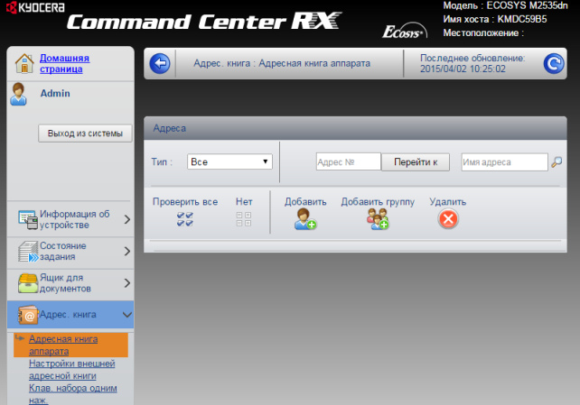 Слева в меню выбираем пункт Адрес. книга -> Адресная книга аппарата. Затем нажимаем на «человечка» Добавить.
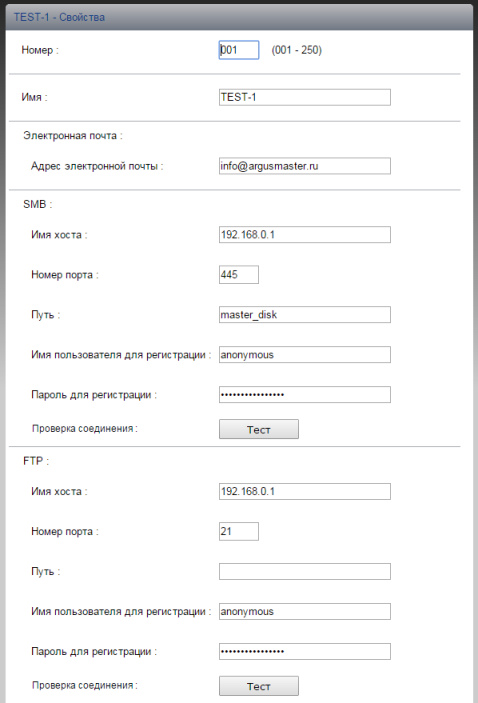
Вот в этом окошке как раз все основные записи. О них поподробнее.
Сканирование возможно по трём направлениям:
1. Электронная почта
2. SMB (сетевая папка)
3. FTP (папка на FTP-сервере)
Можно прописать все три канала, как в нашем примере, или выбрать что-то одно, в зависимости от потребностей.
Номер: — произвольное число.
Имя: — то, что будет показано на экране МФУ.
Электронная почта
Адрес электронной почты: — сюда вписываем адрес получателя скана.
Для отправки на почту на этой страничке больше ничего не требуется. Есть ещё настройки отправителя, но о них чуть позже.
SMB (сетевая папка)
Имя хоста: — имя компьютера (или лучше IP адрес), где находится ваша сетевая папка
Номер порта: — не меняем
Путь: — название самой папки
Имя пользователя для регистрации: — в нашем случае пишем anonymous, т.к. папка доступна без пароля
Пароль для регистрации: — так же пишем anonymous !
Дальше можно нажать кнопку [Тест], аппарат попробует достучаться до папки и если напишет, что ошибок не произошло — это значит, что сканирование в папку успешно настроено!
FTP
Имя хоста: — имя компьютера (или лучше IP адрес), где находится FTP-сервер
Номер порта: — не меняем
Путь: — оставляем пустым, или указываем подпапки.
Имя пользователя для регистрации: — в нашем случае пишем anonymous, т.к. сервер доступен без пароля
Пароль для регистрации: — так же пишем anonymous !
Опять же для проверки можно нажать кнопку [Тест]. Если ошибок нет — сканирование на FTP настроено!
Если всё успешно, сохраняем настройки, нажав внизу странички кнопку [Передать].
И ещё кое-что для настройки отправки почты.
Слева в основном меню выбираем Настройки функций -> Электронная почта
На этой страничке необходимо настроить отправителя почты.
Для этого вам потребуется какой-либо почтовый ящик, от имени которого аппарат будет слать почту.
В нашем примере мы использовали gmail.com и адрес на нём dos.jp@argusmaster.ru
Просто заполните все поля аналогично примеру, используя данные вашего почтового сервера.
Надеемся, что эта статья была Вам полезной.
!! Если Вам необходимо настроить сетевое сканирование через TWAIN драйвер с помощью компютера, подробную инструкцию можно прочитать по этой ссылке.
Kyocera FS-6525MFP это очень хорошее многофункциональное устройство (МФУ) с максимальным форматом А3. Как правило такие аппараты используют несколько сотрудников или целый офис если он не большой. Для удобства можно настроить сканирование в сетевую папку. Давайте рассмотрим, как это можно сделать на примере Kyocera FS-6525MFP, данная инструкция подойдет и для других моделей.
Самые популярные статьи по теме.
Настройка сканирования в папку
Настроить сканирование в сетевую папку можно двумя способами с самого аппарата или по сети. Второй вариант намного удобней по этому будем использовать именно его. Первое что вам нужно сделать это узнать IP адрес вашего устройства. Его можно распечатать с самого МФУ если зайти в настройки. Дальше открываем браузер и вводим IP. После чего откроется домашняя страница.
Для начала нужно проверить включен ли необходимый протокол. Для этого нужно ввести логина пароль администратора по умолчанию для этого устройства это Admin Admin.
Дальше открываем Параметры.
Переходим на вкладку «Сканер» и слева в списке выбираем пункт «SMB». Проверяем включен ли данный сетевой протокол и указан ли порт. Если все включено то переходим обратно кликаем «Домашняя страница».
Слева выбираем «Адресная книга» И жмем добавить контакт.
Вводим номер контакта, дальше указываем имя. Теперь в блоке «SMB» указываем имя хоста (IP адрес компьютера где расположена сетевая папка). Порт оставляем по умолчанию. В поле путь указываем название расшаренной папки. Дальше вводим имя пользователя и пароль и запускаем проверку соединения.
Если вы все ввели правильно то должны увидеть сообщение.
Теперь идем к устройству и пробуем сканировать в сетевую папку. Для этого нужно на устройстве нажать «Отправить» дальше зайти в «Контакты» выбрать созданный контакт и нажать Старт.
Рассмотрим настройку сетевого сканирования в папку на примере Kyocera fs-1035mfp.
1) Открываем веб-браузер и вводим в адресную строку присвоенный раннее ip-адрес мфу.
2) При открытии Kyocera command center нам необходимо зайти в систему и ввести пароль ( В предыдущей статье мы рассмотрели как зайти в веб-интерфейс Kyocera) в нашем случае пароль — admin00
3) В верхнем меню переходим во вкладку «Основные», далее в левом меню выбираем раздел «Адресная книга» — «Контакты».
4) В открывшемся разделе нажимаем «добавить контакт».
5) Заполняем поле «Имя» контакта — которое будет отображаться на мфу.
6) Заполняем поле «Имя хоста» — вводится либо имя компьютера либо его ip-адрес, на который будут сканироваться документы.
7) Заполняем поле «путь» — путь к папке в которую будут отправляться отсканированные документы.
Заполняем поле «Имя пользователя для регистрации» — имя пользователя для входа в компьютер или домен.
9) Заполняем поле «Пароль для регистрации» — пароль от имени пользователя для входа в компьютер или домен .
10) Нажимаем клавишу «передать».
Теперь необходимо проверить сетевое сканирование в папку:
1) На аппарате Kyocera нажимаем клавишу «Отправить(электронная почта/папка)»
2) Затем нажимаем клавишу «Адресная книга».
3) Выбираем созданную запись и нажимаем 2(два) раза клавишу «OK»
4) После появления надписи «Готов к передаче» нажимаем клавишу «Старт»
5) Если все настройки были выполнены верно — то в указанной папке для сканирования появится отсканированный документ.
Если у вас не получается настроить сетевое сканирование или печать, то наши специалисты помогут Вам в этом
Звоните менеджерам компании Kyomart +7 (343) 288-23-45 .
Windows 10 kyocera не сканирует smb ошибка соединения
![]()
Вопрос
![]()
![]()
Ответы
![]()
![]()
У меня аппараты куасера при указании пути и пользователя рядом есть кнопка тестировать. Нажимаешь и сразу проверяешь имеются права доступа или нет.
Добавьте пользователя на машину с Win 10 под которым производите сканирование.
Отключите брандмауер и защитник. Если проблема после этого устранена значит ищите проблему в нем. Антивирус какой? У меня на доктор вебе стоит ограничение в офисном контроле на сканеры и прочее оборудование.
Папку как расшаривали? Только общий доступ?
Добавьте пользователя под которым происходит сканирование во вкладке общий доступ и поставьте права совладельца и во вкладке безопасность и проставьте (все) галочки.
Все ответы
![]()
![]()
Воткнуть его в сеть и повторить попытку сканирования на сетевую шару не пробовали?
Уточните ошибку, возможно дело в SMB 1 -?
Я не волшебник, я только учусь MCP CCNA. Если Вам помог чей-либо ответ, пожалуйста, не забывайте жать на кнопку «Пометить как ответ» или проголосовать «полезное сообщение». Мнения, высказанные здесь, являются отражением моих личных взглядов, а не позиции работодателя. Вся информация предоставляется как есть без каких-либо гарантий. Блог IT Инженера, Twitter, YouTube, GitHub.
![]()
![]()
![]()
![]()
Проверьте, что на ПК с Windows 10 включен протокол SMB 1 и попробуйте отсканировать.
Как проверить, включить/выключить SMB:
![]()
![]()
Добрый день. Возникла проблема с сетевым сканированием на пк в папку с общим доступом. МФУ Kyocera fs-6525. на пк с win 7 сканирование идет без проблем. с 10кой сканер выдает ошибку. к папке доступ точно есть на запись и чтение. Помогите с данным вопросом
![]()
![]()
![]()
![]()
![]()
![]()
У меня аппараты куасера при указании пути и пользователя рядом есть кнопка тестировать. Нажимаешь и сразу проверяешь имеются права доступа или нет.
Добавьте пользователя на машину с Win 10 под которым производите сканирование.
Отключите брандмауер и защитник. Если проблема после этого устранена значит ищите проблему в нем. Антивирус какой? У меня на доктор вебе стоит ограничение в офисном контроле на сканеры и прочее оборудование.
Папку как расшаривали? Только общий доступ?
Добавьте пользователя под которым происходит сканирование во вкладке общий доступ и поставьте права совладельца и во вкладке безопасность и проставьте (все) галочки.
![]()
![]()
![]()
![]()
Уважаемый RomanLRV, данная тема имеет решение и не Актуальна.
Не стоит заниматься некропостингом.
Надеюсь на понимание
Я не волшебник, я только учусь MCP, CCNA. Если Вам помог чей-либо ответ, пожалуйста, не забывайте нажать на кнопку «Пометить как ответ» или проголосовать за полезное сообщение. Мнения, высказанные здесь, являются отражением моих личных взглядов, а не позиции работодателя. Вся информация предоставляется как есть без каких-либо гарантий. Блог IT Инженера, Twitter, YouTube, GitHub, Instagram
![]()
![]()
Напыщенное безграмотное тело. Баллы рейтинга — нарисовал себе сам, т.к. одим дал ему лишние права очевидно на этом форуме.
Во-первых: Проблема не решена! Имеем лицензионное г-но windows 10 сборки 1909, smb 100500% включено, как и автор первоначального проблемы здесь, я много киосер вводил в эксплуатацию и всегда без проблем, особенно на win 7 (если исключить ввод киосер на домашние сборки, когда искусственно скидываются задания из планировщика при обновлениях на скрипт переустановки нуджного для киосеры пароля для киосеровского пользователя)
Во-вторых: Уважаемый модератор! Понятно что у Вас бомбанет я буду отправлен в бан а сообщение вскоре пропадет из поста, но потрудитесь в будуще пошевелить Вашей могучей 5-й точкой опубликовать несложную конструкцию: Решение: и цитата на решение, перед закрытием темы с очень умным видом, хотя выглядите Вы при этом крайне глупо и напыщено и ничего такими комментариями положительного у людей не вызываете. Не стоит заниматься некропостингом. Не стоит использовать мелкомягкий некрософт.
![]()
![]()
Пока не словил бан, и надеюсь Модератор хоть от своего имени перепубликует РЕАЛЬНОЕ РЕШЕНИЕ:
1. CMD от имени администратора
2. пишем : powershell.exe Enable-WindowsOptionalFeature -Online -FeatureName smb1protocol
3. Остальные настройки как на windows 7 и работаем с поддержкой kyoera, если не получается
На чтение 6 мин. Просмотров 2k. Опубликовано 15.12.2019
Настройки сетевого сканирования полностью идентичны для всех моделей KYOCERA ECOSYS M2040dn / M2540dn / M2035dn / M2535dn
На самом деле всё довольно-таки просто!
Предполагается, что аппарат уже настроен, и работает как принтер, и автоматически получил все сетевые настройки через DHCP.
Для начала заходим на WEB-страничку аппарата по его IP адресу через браузер.
Необходимо авторизоваться. Логин Admin, пароль тоже Admin. Обратите внимание, буквы A заглавные!
Слева в меню выбираем пункт Адрес. книга -> Адресная книга аппарата. Затем нажимаем на «человечка» Добавить.
Вот в этом окошке как раз все основные записи. О них поподробнее.
Сканирование возможно по трём направлениям:
1. Электронная почта
2. SMB (сетевая папка)
3. FTP (папка на FTP-сервере)
Можно прописать все три канала, как в нашем примере, или выбрать что-то одно, в зависимости от потребностей.
Номер: — произвольное число.
Имя: — то, что будет показано на экране МФУ.
Электронная почта
Адрес электронной почты: — сюда вписываем адрес получателя скана.
Для отправки на почту на этой страничке больше ничего не требуется. Есть ещё настройки отправителя, но о них чуть позже.
SMB (сетевая папка)
Имя хоста: — имя компьютера (или лучше IP адрес), где находится ваша сетевая папка
Номер порта: — не меняем
Путь: — название самой папки
Имя пользователя для регистрации: — в нашем случае пишем anonymous, т.к. папка доступна без пароля
Пароль для регистрации: — так же пишем anonymous !
Дальше можно нажать кнопку [Тест], аппарат попробует достучаться до папки и если напишет, что ошибок не произошло — это значит, что сканирование в папку успешно настроено!
FTP
Имя хоста: — имя компьютера (или лучше IP адрес), где находится FTP-сервер
Номер порта: — не меняем
Путь: — оставляем пустым, или указываем подпапки.
Имя пользователя для регистрации: — в нашем случае пишем anonymous, т.к. сервер доступен без пароля
Пароль для регистрации: — так же пишем anonymous !
Опять же для проверки можно нажать кнопку [Тест]. Если ошибок нет — сканирование на FTP настроено!
Если всё успешно, сохраняем настройки, нажав внизу странички кнопку [Передать].
И ещё кое-что для настройки отправки почты.
Слева в основном меню выбираем Настройки функций -> Электронная почта
На этой страничке необходимо настроить отправителя почты.
Для этого вам потребуется какой-либо почтовый ящик, от имени которого аппарат будет слать почту.
В нашем примере мы использовали gmail.com и адрес на нём dos.jp@argusmaster.ru
Просто заполните все поля аналогично примеру, используя данные вашего почтового сервера.
Надеемся, что эта статья была Вам полезной.
!! Если Вам необходимо настроить сетевое сканирование через TWAIN драйвер с помощью компютера, подробную инструкцию можно прочитать по этой ссылке.
Kyocera FS-6525MFP это очень хорошее многофункциональное устройство (МФУ) с максимальным форматом А3. Как правило такие аппараты используют несколько сотрудников или целый офис если он не большой. Для удобства можно настроить сканирование в сетевую папку. Давайте рассмотрим, как это можно сделать на примере Kyocera FS-6525MFP, данная инструкция подойдет и для других моделей.
Самые популярные статьи по теме.
Настройка сканирования в папку
Настроить сканирование в сетевую папку можно двумя способами с самого аппарата или по сети. Второй вариант намного удобней по этому будем использовать именно его. Первое что вам нужно сделать это узнать IP адрес вашего устройства. Его можно распечатать с самого МФУ если зайти в настройки. Дальше открываем браузер и вводим IP. После чего откроется домашняя страница.
Для начала нужно проверить включен ли необходимый протокол. Для этого нужно ввести логина пароль администратора по умолчанию для этого устройства это Admin Admin.
Дальше открываем Параметры.
Переходим на вкладку «Сканер» и слева в списке выбираем пункт «SMB». Проверяем включен ли данный сетевой протокол и указан ли порт. Если все включено то переходим обратно кликаем «Домашняя страница».
Слева выбираем «Адресная книга» И жмем добавить контакт.
Вводим номер контакта, дальше указываем имя. Теперь в блоке «SMB» указываем имя хоста (IP адрес компьютера где расположена сетевая папка). Порт оставляем по умолчанию. В поле путь указываем название расшаренной папки. Дальше вводим имя пользователя и пароль и запускаем проверку соединения.
Если вы все ввели правильно то должны увидеть сообщение.
Теперь идем к устройству и пробуем сканировать в сетевую папку. Для этого нужно на устройстве нажать «Отправить» дальше зайти в «Контакты» выбрать созданный контакт и нажать Старт.
Рассмотрим настройку сетевого сканирования в папку на примере Kyocera fs-1035mfp.
1) Открываем веб-браузер и вводим в адресную строку присвоенный раннее ip-адрес мфу.
2) При открытии Kyocera command center нам необходимо зайти в систему и ввести пароль ( В предыдущей статье мы рассмотрели как зайти в веб-интерфейс Kyocera) в нашем случае пароль — admin00
3) В верхнем меню переходим во вкладку «Основные», далее в левом меню выбираем раздел «Адресная книга» — «Контакты».
4) В открывшемся разделе нажимаем «добавить контакт».
5) Заполняем поле «Имя» контакта — которое будет отображаться на мфу.
6) Заполняем поле «Имя хоста» — вводится либо имя компьютера либо его ip-адрес, на который будут сканироваться документы.
7) Заполняем поле «путь» — путь к папке в которую будут отправляться отсканированные документы.
Заполняем поле «Имя пользователя для регистрации» — имя пользователя для входа в компьютер или домен.
9) Заполняем поле «Пароль для регистрации» — пароль от имени пользователя для входа в компьютер или домен .
10) Нажимаем клавишу «передать».
Теперь необходимо проверить сетевое сканирование в папку:
1) На аппарате Kyocera нажимаем клавишу «Отправить(электронная почта/папка)»
2) Затем нажимаем клавишу «Адресная книга».
3) Выбираем созданную запись и нажимаем 2(два) раза клавишу «OK»
4) После появления надписи «Готов к передаче» нажимаем клавишу «Старт»
5) Если все настройки были выполнены верно — то в указанной папке для сканирования появится отсканированный документ.
Если у вас не получается настроить сетевое сканирование или печать, то наши специалисты помогут Вам в этом
Звоните менеджерам компании Kyomart +7 (343) 288-23-45 .
![]()
Kyocera. 1102 ошибка
Перевод описания ошибки из сервисного руководства:
1102. Подсоединение к компьютеру не удалось:
- Подтвердите имя пользователя и пароль.
- Проверьте правильность параметров сети, к которой подключено устройство.
- Проверьте компьютер, если папка правильно размещена.
1102 ошибка может возникать при:
- Передаче через SMB‐сервер. Проверьте параметры настройки SMB:
- имя пользователя и пароль при входе;
Примечание: Если отправитель является пользователем домена, укажите имя домена.
- имя хоста;
- путь.
- Передаче электронного письма. Проверьте следующие настройки в COMMAND CENTER:
- имя пользователя и пароль для сервера SMTP;
- имя пользователя и пароль для сервера POP3.
- Передаче через FTP‐сервер. Проверьте параметры настройки FTP‐сервера:
- имя пользователя и пароль при входе;
Примечание: Если отправитель является пользователем домена, укажите имя домена.
- путь;
- право доступа получателя к папке.
Распространённые ошибки настройки: скорее всего, вы ввели короткий логин для доступа к папке вместо полного. Полный логин содержит имя домена (для доменной учётной записи), например: DOMAINUserLogin. (Для локального пользователя — просто UserLogin.) Если это условие выполнено, но ошибка появляется, проверьте настройки сетевого экрана (в качестве быстрой проверки (не рекомендуется) можно временно его полностью отключить). Также проверьте путь к папке сканирования (он должен быть максимально коротким (не более двух слешей).
Причины сбоев и ошибок:
- Постоянная или временная недоступность настроенного сетевого ресурса.
- Ограничение на допустимое количество символов в имени компьютера, имени пользователя и пароле — не более 64. Путь к сетевой папке не должен содержать более 128 символов.
- Ошибка 1102 может возникать при использовании короткого логина вместо полного («имя домена имя пользователя (без кавычек и пробелов около косой черты).
- Неверный путь к сетевой папке. Например, указан локальный путь, а не сетевой.
- Если все сохраненные значения параметров верны, а при попытке сканирования возникает ошибка, проверьте настройки сетевого экрана (firewall’а — ‘брандмауэра’), возможно, что в сетевых правилах существует запись с более высоким приоритетом, блокирующая порт.
 Чтобы избежать ситуаций с возникновением ошибок, необходимо изначально правильно настроить оборудование.
Настройка компьютера:
- Проверьте сетевое полное имя компьютера (хоста), домен и имя пользователя и запишите значения. Пользователи Windows в командной строке могут набрать net config workstation либо получить нужные значения через «Свойства системы.
- Создайте сетевую папку и настройте права доступа в ней. В общей папке можно создать подпапку в качестве расположения для передачи данных. В этом случае в поле «Путь нужно ввести «Имя общей папки Имя подпапки (без кавычек и пробелов около косой черты).
- Включите общий доступ для файлов и принтеров и (если необходимо) настройте правило для входящих подключений: 139 порт по протоколу TCP. 139 — порт по умолчанию, но он может быть изменен (см. Руководство пользователя).
Настройка МФУ:
-
- Убедитесь, что в COMMAND CENTER включены протоколы SMB и FTP (подробная информация изложена в руководстве пользователя, в том числе правило ввода символов).
- Положите оригинал на стекло, нажмите клавишу «Отправить.
- Выберите направление передачи: папка SMB или папка FTP.
- Введите имя компьютера.
- Введите имя папки, заданное в параметрах общего доступа.
- Введите имя и пароль пользователя, которые используются для входа в компьютер с папкой общего доступа.
- В случае удачной проверки нажмите «Подтвердить адресат и клавишу «Старт.
Примечание: При внесении неправильных данных могут возникать ошибки с кодами 1102, 1103 и 3101 при проблемах с FTP‐сервером.
Kyocera. Ошибка 1103
Может быть при сканировании может появиться при:
- Передаче через SMB‐сервер. Проверьте параметры настройки SMB:
- имя пользователя и пароль при входе;
Примечание: Если отправитель является пользователем домена, укажите имя домена.
- путь;
- право доступа получателя к папке.
- Передаче через FTP‐сервер. Проверьте параметры настройки FTP‐сервера:
- путь;
- право доступа получателя к папке.
Ошибка 1105 Kyocera
может быть при:
- Передаче через SMB‐сервер. Проверьте следующие настройки в COMMAND CENTER:
- задайте значение «Вкл. для настроек SMB‐сервера.
- Передаче электронного письма. Проверьте следующие настройки в COMMAND CENTER:
- задайте значение «Вкл. для настроек SMTP‐сервера.
- Передаче через FTP‐сервер. Проверьте следующие настройки в COMMAND CENTER:
- задайте значение «Вкл. для настроек FTP‐сервера.
-
#1
Вобщем, имеется МФУ Kyocera Ecosys m2530dn, подключён через роутер к домашней сети. Без проблем печатает всё, что нужно. Хотел настроить сканирование в сетевую папку. Создал её на диске, где установлена Windows10, расшарил её по-максимуму. Зашёл в админку МФУ. Как написано в интернетах, в Адресной книге добавил новую запись, заполнил всё в разделе SMB, жму «Тест», чтобы проверить соединение, но итог всегда один — «Ошибка соединения». По-всякому пробовал — прописывал имя хоста и именем в сети, и IP-адресом, не помогает. Отключал брендмауэр, та же история. Помогите, пож, разобраться
-
#2
Включено ли в десятке сетевое обнаружение?
-
#3
Попробуйте включить брандмауэр но разрешить любые соединения на tcp 445 и 139 порт
-
#4
в киосере в админке отключите лишние протоколы, bonjour и прочую хрень, шифрование тоже отключить
-
#5
где то в адресной книге мфу указываются учетные данные пользователя с которыми мфу будет пытаться получить доступ к smb шаре yourfolder
Ответ в вебадминке kyocera — адресная книга
-
#6
Включено ли в десятке сетевое обнаружение?
Видимо, да, т.к. через Сеть видно расшаренную папку (прилагаю скрин)

-
#7
Попробуйте включить брандмауэр но разрешить любые соединения на tcp 445 и 139 порт
Пож, подскажите, как это сделать, мои знания тут невелики
-
#8
в киосере в админке отключите лишние протоколы, и прочую хрень, шифрование тоже отключить
Из перечисленного только bonjour нашёл, отключил. Остальных параметров очень много, боюсь что-нибудь важное вырубить


-
#9
Из перечисленного только bonjour нашёл, отключил. Остальных параметров очень много, боюсь что-нибудь важное вырубить
Посмотреть вложение 11073
Посмотреть вложение 11074
отключите везде tls и ssl, отальное шифрование тоже, затем проверьте кнопкой тест соединения
-
#10
где то в адресной книге мфу указываются учетные данные пользователя с которыми мфу будет пытаться получить доступ к smb шаре yourfolder
Ответ в вебадминке kyocera — адресная книга
Вот как заполняю Адресную книгу для smb

Вот что имею в итоге после Теста:

-
#11
пример работающего варианта

-
#12
на 192.168.1.3 должен быть пользователь anyuser и должен името доступ в папку
-
#13
на 192.168.1.3 должен быть пользователь anyuser и должен името доступ в папку
Попробовал по вашему примеру вот так

Но всё равно выдаёт ошибку соединения. Пользователь admin есть, доступ к расшаренной папке он имеет. Пароль, вот только не пойму какой вводить, ввёл пароль на Wi-Fi. Пароля на вход в Win нет
-
#14
Пароль от вайфая тут не нужен. В компе зайдите и создайте пользователя admin. Дайте ему какой нибудь простой пароль — 123, далее свойства папки Scanner — Безопасность — добавьте туда пользователя admin и назначьте ему полные права

-
#15
сотрите email. Может он у вас пытается соединиться с почтовым сервером а не с расшаренной папкой
-
#16
Пароль от вайфая тут не нужен. В компе зайдите и создайте пользователя admin. Дайте ему какой нибудь простой пароль — 123, далее свойства папки Scanner — Безопасность — добавьте туда пользователя admin и назначьте ему полные права
Пользователь admin уже есть. Я для простоты для этой папки (Scaner) дал все права для Всех (как на скрине ниже)

-
#17
сотрите email. Может он у вас пытается соединиться с почтовым сервером а не с расшаренной папкой
Нет, так я уже пробовал. Не работает ни с почтой, ни без неё
-
#18
Такой ещё вариант попробовал, не работает


DOC
Активный участник
-
#19
хм. Можно ли зайти в расшаренную папку с другого устройства в сети ? Может есть ноутбук или планшет или еще что-то ? Может все таки обще го доступа нет к папке.. Может NTFS права
Принтер же через сетевой провод воткнут а не через USB ?
-
#20
хм. Можно ли зайти в расшаренную папку с другого устройства в сети ? Может есть ноутбук или планшет или еще что-то ? Может все таки обще го доступа нет к папке.. Может NTFS права
Принтер же через сетевой провод воткнут а не через USB ?
он же на веб морду через 101 ip заходит
- Code: 0030
- Description: FAX control PWB system error
Processing with the fax software was disabled due to a hardware problem. - Causes: Defective FAX control PWB.
- Remedy: Replace the fax control PWB and check for correct operation.
- Code: 0070
- Description: FAX control PWB incompatible detection error
Abnormal detection of FAX control PWB incompatibility In the initial communication with the FAX control PWB, any normal communication command is not transmitted. - Causes: Defective FAX software.
Defective FAX control PWB. - Remedy: Defective FAX software. Install the fax software.
Defective FAX control PWB. Replace the fax control PWB and check for correct operation.
- Code: 0100
- Description: Backup memory device error
- Causes: Defective flash memory.
Defective main PWB. - Remedy: Defective flash memory. Replace the main PWB and check for correct operation.
Defective main PWB. Replace the main PWB and check for correct operation.
- Code: 0120
- Description: MAC address data error
For data in which the MAC address is invalid. - Causes: Defective flash memory.
Defective engine PWB. - Remedy: Defective flash memory. Replace the main PWB and check for correct operation.
Defective engine PWB. Replace the engine PWB and check for correct operation.
- Code: 0150
- Description: Backup memory read/write error (engine PWB)
No response is issued from the device in reading/writing for 5 ms or more and this problem is repeated 5 times successively. Mismatch of reading data from 2 locations occurs 8 times successively. Mismatch between writing data and reading data occurs 8 times successively. - Causes: Improper installation EEPROM.
Device damage of EEPROM. - Remedy: Improper installation EEPROM. Check the installation of the EEPROM and remedy if necessary.
Defective engine PWB. Replace the engine PWB and check for correct operation.
Device damage of EEPROM. Contact the Service Administrative Division.
- Code: 0160
- Description: Backup memory data error
(engine PWB) Reading data from EEPROM is abnormal. - Causes: Data damage of EEPROM.
- Remedy: Contact the Service Administrative Division.
- Code: 0170
- Description: Billing counting error
A checksum error is detected in the main and engine backup memories for the billing counters. - Causes: Data damage of EEPROM.
Defective PWB. - Remedy: Data damage of EEPROM. Contact the Service Administrative Division.
Defective PWB. Replace the main PWB or the engine PWB and check for correct operation.
- Code: 0180
- Description: Machine number mismatch
Machine number of main and engine does not match. - Causes: Data damage of EEPROM.
- Remedy: Data damage of EEPROM. Contact the Service Administrative Division.
- Code: 0620
- Description: FAX image DIMM error
DIMM is not installed correctly. DIMM cannot be accessed. - Causes: DIMM installed incorrectly.
Defective main PWB. - Remedy: DIMM installed incorrectly. Check if the DIMM is inserted into the socket on the main PWB correctly.
Defective main PWB. Replace the main PWB and check for correct operation.
- Code: 0630
- Description: DMA error
DMA transmission of image data does not complete within the specified period of time. - Causes: Poor contact in the connector terminals.
Defective main PWB. - Remedy: Poor contact in the connector terminals. Check the connection the signal cable for CIS and the main PWB, and the continuity across the connector terminals. Repair or replace if necessary.
Defective main PWB. Replace the main PWB and check for correct operation.
- Code: 0640
- Description: Hard disk error
The hard disk cannot be accessed. - Causes: Defective hard disk.
Defective main PWB. - Remedy: Defective hard disk. Replace the hard disk and check for correct operation.
Defective main PWB. Replace the main PWB and check for correct operation.
- Code: 0650
- Description: FAX image DIMM check error
Improper DIMM is installed. - Causes: DIMM installed incorrectly.
Defective main PWB. - Remedy: DIMM installed incorrectly. Check if the DIMM is inserted into the socket on the main PWB correctly.
Defective main PWB. Replace the main PWB and check for correct operation.
- Code: 0800
- Description: Image processing error
JAM010X is detected twice. - Causes: Defective main PWB.
- Remedy: Replace the main PWB and check for correct operation.
- Code: 0830
- Description: FAX control PWB flash program area checksum error
A checksum error occurred with the program of the FAX control PWB. - Causes: Defective FAX software.
Defective FAX control PWB. - Remedy: Defective FAX software. Install the fax software.
Defective FAX control PWB. Replace the fax control PWB and check for correct operation.
- Code: 0840
- Description: Faults of RTC
The time is judged to go back based on the comparison of the RTC time and the current time or five years or more have passed. - Causes: The battery is disconnected from the main PWB.
Defective main PWB. - Remedy: The battery is disconnected from the main PWB. Check visually and remedy if necessary
Defective main PWB. Replace the main PWB and check for correct operation.
- Code: 0870
- Description: FAX control PWB to main PWB high capacity data transfer error
High-capacity data transfer between the FAX control PWB and the main PWB of the machine was not normally performed even if the data transfer was retried the specified times. - Causes: Improper installation FAX control PWB.
Defective FAX control PWB or main PWB. - Remedy: Improper installation FAX control PWB. Reinstall the FAX control PWB.
Defective FAX control PWB or main PWB. Replace the FAX control PWB or main PWB and check for correct operation.
- Code: 0900
- Description: FAX software incompatible detection error
Incompatible FAX control PWB is installed. - Causes: Defective FAX software.
Defective FAX control PWB. - Remedy: Defective FAX software. Install the fax software.
Defective FAX control PWB. Replace the fax control PWB and check for correct operation.
- Code: 0920
- Description: Fax file system error
The backup data is not retained for file system abnormality of flash memory of the FAX control PWB. - Causes: Defective FAX control PWB.
- Remedy: Replace the fax control PWB and check for correct operation.
- Code: 0970
- Description: 12 V power down detect
Power is disconnected during sleeping. - Causes: Defective power source PWB.
- Remedy: Replace the power source PWB and check for correct operation.
- Code: 0980
- Description: 24 V power down detect
24V disconnection signal is detected for 1 s and 12V disconnection signal is not detected. - Causes: Defective power source PWB.
- Remedy: Replace the power source PWB and check for correct operation.
- Code: 1000
- Description: MP lift motor error
After the MP lift motor is driven, the ON status of MP lift sensors 1 and 2 cannot be detected for 1.5 s. - Causes: Defective MP plate elevation mechanism.
Defective connector cable or poor contact in the connector.
Defective drive transmission system of motor.
Defective MP lift motor.
Defective engine PWB. - Remedy: Defective MP plate elevation mechanism. Check to see if the MP plate can move smoothly and repair it if any problem is found.
Defective connector cable or poor contact in the connector. Reinsert the connector. Also check for continuity within the connector cable. If none, replace the cable. MP lift motor and relay PWB (YC3) Relay PWB (YC12) and feed PWB 1 (YC17) Feed PWB 1 (YC1) and engine PWB (YC6)
Defective drive transmission system of motor. Check if the gears rotate smoothly. If not, grease the bushes and gears. Check for broken gears and replace if any.
Defective MP lift motor. Replace the MP lift motor.
Defective engine PWB. Replace the engine PWB and check for correct operation.
- Code: 1010
- Description: Lift motor 1 error
After cassette 1 is inserted, lift sensor 1 does not turn on within 12 s. This error is detected 4 times successively. The lock signal of the motor is detected continuously for 1 s. - Causes: Defective bottom plate elevation mechanism in the cassette.
Defective connector cable or poor contact in the connector.
Defective drive transmission system of motor
Defective lift motor 1.
Defective engine PWB. - Remedy: Defective bottom plate elevation mechanism in the cassette. Check to see if the bottom plate can move smoothly and repair it if any problem is found.
Defective connector cable or poor contact in the connector. Reinsert the connector. Also check for continuity within the connector cable. If none, replace the cable. Lift motor 1 and feed PWB 2 (YC3) Feed PWB 2 (YC1) and engine PWB (YC4)
Defective drive transmission system of motor. Check if the gears rotate smoothly. If not, grease the bushes and gears. Check for broken gears and replace if any.
Defective lift motor 1. Replace the lift motor 1.
Defective engine PWB. Replace the engine PWB and check for correct operation.
- Code: 1020
- Description: Lift motor 2 error
After cassette 2 is inserted, lift sensor 2 does not turn on within 12 s. This error is detected 4 times successively. The lock signal of the motor is detected continuously for 1 s. - Causes: Defective bottom plate elevation mechanism in the cassette.
Defective connector cable or poor contact in the connector.
Defective drive transmission system of motor.
Defective lift motor 2.
Defective engine PWB. - Remedy: Defective bottom plate elevation mechanism in the cassette. Check to see if the bottom plate can move smoothly and repair it if any problem is found.
Defective connector cable or poor contact in the connector. Reinsert the connector. Also check for continuity within the connector cable. If none, replace the cable. Lift motor 2 and feed PWB 2 (YC3) Feed PWB 2 (YC1) and engine PWB (YC4)
Defective drive transmission system of motor. Check if the gears rotate smoothly. If not, grease the bushes and gears. Check for broken gears and replace if any.
Defective lift motor 2. Replace the lift motor 2.
Defective engine PWB. Replace the engine PWB and check for correct operation.
- Code: 1030
- Description: PF lift motor 1 error (paper feeder)
After cassette 3 is inserted, PF lift sensor 1 does not turn on within 12 s. This error is detected 5 times successively. During driving the motor, the lift overcurrent protective monitor signal is detected for 1 s or more 5 times successively. However, the first 1 s after motor is turned on is excluded from detection. - Causes: Defective bottom plate elevation mechanism in the cassette.
Defective connector cable or poor contact in the connector.
Defective drive transmission system of motor.
Defective PF lift motor 1.
Defective PF main PWB. - Remedy: Defective bottom plate elevation mechanism in the cassette. Check to see if the bottom plate can move smoothly and repair it if any problem is found.
Defective connector cable or poor contact in the connector. Reinsert the connector. Also check for continuity within the connector cable. If none, replace the cable. PF lift motor 1 and PF main PWB (YC7)
Defective drive transmission system of motor. Check if the gears rotate smoothly. If not, grease the bushes and gears. Check for broken gears and replace if any.
Defective PF lift motor 1. Replace the PF lift motor 1.
Defective PF main PWB. Replace the PF main PWB (Refer to the service manual for the paper feeder).
- Code: 1040
- Description: PF lift motor 2 error (paper feeder)
After cassette 4 is inserted, PF lift sensor 2 does not turn on within 12 s. This error is detected 5 times successively. During driving the motor, the lift overcurrent protective monitor signal is detected for 1 s or more 5 times successively. However, the first 1 s after motor is turned on is excluded from detection. - Causes: Defective bottom plate elevation mechanism in the cassette.
Defective connector cable or poor contact in the connector.
Defective drive transmission system of motor.
Defective PF lift motor 2.
Defective PF main PWB. - Remedy: Defective bottom plate elevation mechanism in the cassette. Check to see if the bottom plate can move smoothly and repair it if any problem is found.
Defective connector cable or poor contact in the connector. Reinsert the connector. Also check for continuity within the connector cable. If none, replace the cable. PF lift motor 2 and PF main PWB (YC7)
Defective drive transmission system of motor. Check if the gears rotate smoothly. If not, grease the bushes and gears. Check for broken gears and replace if any.
Defective PF lift motor 2. Replace the PF lift motor 2.
Defective PF main PWB. Replace the PF main PWB (Refer to the service manual for the paper feeder).
- Code: 1050
- Description: SM lift motor error (side multi tray)
After cassette 5 is inserted, SM lift sensor does not turn on within 12 s. This error is detected 5 times successively. During driving the motor, the lift overcurrent protective monitor signal is detected for 1 s or more 5 times successively. However, the first 1 s after motor is turned on is excluded from detection. - Causes: Defective bottom plate elevation mechanism in the cassette.
Defective connector cable or poor contact in the connector.
Defective drive transmission system of motor.
Defective SM lift motor.
Defective SM main PWB. - Remedy: Defective bottom plate elevation mechanism in the cassette. Check to see if the bottom plate can move smoothly and repair it if any problem is found.
Defective connector cable or poor contact in the connector. Reinsert the connector. Also check for continuity within the connector cable. If none, replace the cable. SM lift motor and SM main PWB (YC5)
Defective drive transmission system of motor. Check if the gears rotate smoothly. If not, grease the bushes and gears. Check for broken gears and replace if any.
Defective SM lift motor. Replace the SM lift motor.
Defective SM main PWB. Replace the SM main PWB (Refer to the service manual for the paper feeder).
- Code: 1060
- Description: PF lift motor 1 error (side paper feeder)
After cassette 6 is inserted, PF lift sensor 1 does not turn on within 12 s. This error is detected 5 times successively. During driving the motor, the lift overcurrent protective monitor signal is detected for 1 s or more 5 times successively. However, the first 1 s after motor is turned on is excluded from detection. - Causes: Defective bottom plate elevation mechanism in the cassette.
Defective connector cable or poor contact in the connector.
Defective drive transmission system of motor.
Defective PF lift motor 1.
Defective PF main PWB. - Remedy: Defective bottom plate elevation mechanism in the cassette. Check to see if the bottom plate can move smoothly and repair it if any problem is found.
Defective connector cable or poor contact in the connector. Reinsert the connector. Also check for continuity within the connector cable. If none, replace the cable. PF lift motor 1 and PF main PWB (YC7)
Defective drive transmission system of motor. Check if the gears rotate smoothly. If not, grease the bushes and gears. Check for broken gears and replace if any.
Defective PF lift motor 1. Replace the PF lift motor 1.
Defective PF main PWB. Replace the PF main PWB (Refer to the service manual for the paper feeder).
- Code: 1070
- Description: PF lift motor 2 error (side paper feeder)
After cassette 7 is inserted, PF lift sensor 2 does not turn on within 12 s. This error is detected 5 times successively. During driving the motor, the lift overcurrent protective monitor signal is detected for 1 s or more 5 times successively. However, the first 1 s after motor is turned on is excluded from detection. - Causes: Defective bottom plate elevation mechanism in the cassette.
Defective connector cable or poor contact in the connector.
Defective drive transmission system of motor.
Defective PF lift motor 2.
Defective PF main PWB. - Remedy: Defective bottom plate elevation mechanism in the cassette. Check to see if the bottom plate can move smoothly and repair it if any problem is found.
Defective connector cable or poor contact in the connector. Reinsert the connector. Also check for continuity within the connector cable. If none, replace the cable. PF lift motor 2 and PF main PWB (YC7)
Defective drive transmission system of motor. Check if the gears rotate smoothly. If not, grease the bushes and gears. Check for broken gears and replace if any.
Defective PF lift motor 2. Replace the PF lift motor 2.
Defective PF main PWB. Replace the PF main PWB (Refer to the service manual for the paper feeder).
- Code: 1100
- Description: PF lift motor 1 error (large capacity feeder)
After cassette 3 is inserted, PF lift sensor 1 does not turn on within 12 s. This error is detected 2 times successively. During driving the motor, the lift overcurrent protective monitor signal is detected for 500 ms or more 2 times successively. However, the first 1 s after PF lift motor 1 is turned on is excluded from detection. - Causes: Defective connector cable or poor contact in the connector.
Defective drive transmission system of motor.
Defective PF lift motor 1.
Defective PF main PWB. - Remedy: Defective connector cable or poor contact in the connector. Reinsert the connector. Also check for continuity within the connector cable. If none, replace the cable. PF lift motor 1 and PF main PWB (YC7)
Defective drive transmission system of motor. Check if the gears rotate smoothly. If not, grease the bushes and gears. Check for broken gears and replace if any.
Defective PF lift motor 1. Replace the PF lift motor 1.
Defective PF main PWB. Replace the PF main PWB (Refer to the service manual for the paper feeder).
- Code: 1110
- Description: PF lift motor 2 error (large capacity feeder)
After cassette 4 is inserted, PF lift sensor 2 does not turn on within 12 s. This error is detected 2 times successively. During driving the motor, the lift overcurrent protective monitor signal is detected for 500 ms or more 2 times successively. However, the first 1 s after PF lift motor 2 is turned on is excluded from detection. - Causes: Defective connector cable or poor contact in the connector.
Defective drive transmission system of motor.
Defective PF lift motor 2.
Defective PF main PWB. - Remedy: Defective connector cable or poor contact in the connector. Reinsert the connector. Also check for continuity within the connector cable. If none, replace the cable. PF lift motor 2 and PF main PWB (YC7)
Defective drive transmission system of motor. Check if the gears rotate smoothly. If not, grease the bushes and gears. Check for broken gears and replace if any.
Defective PF lift motor 2. Replace the PF lift motor 2.
Defective PF main PWB. Replace the PF main PWB (Refer to the service manual for the paper feeder).
- Code: 1140
- Description: SD lift motor error (side deck)
After cassette 5 is inserted, SD lift sensor does not turn on within 30 s. The lock signal of the motor is detected continuously for 200 ms. - Causes: Defective connector cable or poor contact in the connector.
Defective drive transmission system of motor.
Defective SD lift motor.
Defective SD main PWB. - Remedy: Defective connector cable or poor contact in the connector. Reinsert the connector. Also check for continuity within the connector cable. If none, replace the cable. SD lift motor and SD main PWB (YC8)
Defective drive transmission system of motor. Check if the gears rotate smoothly. If not, grease the bushes and gears. Check for broken gears and replace if any.
Defective SD lift motor. Replace the SD lift motor.
Defective SD main PWB. Replace the SD main PWB (Refer to the service manual for the paper feeder).
- Code: 1250
- Description: SM multi feed sensor communication error (side multi tray)
A communication error is detected 3 times in succession. - Causes: Improper installation side multi tray.
Defective connector cable or poor contact in the connector.
Defective engine PWB.
Defective SM main PWB. - Remedy: Improper installation side multi tray. Follow installation instruction carefully again.
Defective connector cable or poor contact in the connector. Reinsert the connector. Also check for continuity within the connector cable. If none, replace the cable. SM main PWB (YC1) and engine PWB (YC19)
Defective engine PWB. Replace the engine PWB and check for correct operation.
Defective SM main PWB. Replace the SM main PWB (Refer to the service manual for the paper feeder).
- Code: 1350
- Description: SM multi feed sensor error (side multi tray)
The SM multi feed sensor has signaled the presence of paper for 10 ms continuously. - Causes: Defective connector cable or poor contact in the connector.
Defective SM multi feed sensor.
Defective SM main PWB. - Remedy: Defective connector cable or poor contact in the connector. Reinsert the connector. Also check for continuity within the connector cable. If none, replace the cable. SM multi feed sensor and SM main PWB (YC11)
Defective SM multi feed sensor. Replace the SM multi feed sensor.
Defective SM main PWB. Replace the SM main PWB (Refer to the service manual for the paper feeder).
- Code: 1450
- Description: SM multi feed sensor backup error (side multi tray)
When writing the data, read and write data does not match 3 times in succession. - Causes: Defective connector cable or poor contact in the connector.
Defective SM multi feed sensor.
Defective SM main PWB. - Remedy: Defective connector cable or poor contact in the connector. Reinsert the connector. Also check for continuity within the connector cable. If none, replace the cable. SM multi feed sensor and SM main PWB (YC11)
Defective SM multi feed sensor. Replace the SM multi feed sensor.
Defective SM main PWB. Replace the SM main PWB (Refer to the service manual for the paper feeder).
- Code: 1710
- Description: Side multi tray incompatible detection error
The side multi tray has been installed with a device to which it is incompatible. - Causes: The side multi tray is installed with a device to which it is incompatible.
- Remedy: The side multi tray must be installed with the devices to which it is compatible.
- Code: 1720
- Description: Paper feeder incompatible detection error
The paper feeder has been installed with a device to which it is incompatible. - Causes: The paper feeder is installed with a device to which it is incompatible.
- Remedy: The paper feeder must be installed with the devices to which it is compatible.
- Code: 1800
- Description: Paper feeder communication error
A communication error from paper feeder is detected 10 times in succession. - Causes: Improper installation paper feeder.
Defective connector cable or poor contact in the connector.
Defective engine PWB.
Defective PF main PWB. - Remedy: Improper installation paper feeder. Follow installation instruction carefully again.
Defective connector cable or poor contact in the connector. Reinsert the connector. Also check for continuity within the connector cable. If none, replace the cable. PF main PWB (YC13) and engine PWB (YC19)
Defective engine PWB. Replace the engine PWB and check for correct operation.
Defective PF main PWB. Replace the PF main PWB (Refer to the service manual for the paper feeder).
- Code: 1810
- Description: Side multi tray communication error
A communication error from paper feeder is detected 10 times in succession. - Causes: Improper installation side multi tray.
Defective connector cable or poor contact in the connector.
Defective engine PWB.
Defective SM main PWB. - Remedy: Improper installation side multi tray. Follow installation instruction carefully again.
Defective connector cable or poor contact in the connector. Reinsert the connector. Also check for continuity within the connector cable. If none, replace the cable. SM main PWB (YC1) and engine PWB (YC19)
Defective engine PWB. Replace the engine PWB and check for correct operation.
Defective SM main PWB. Replace the SM main PWB (Refer to the service manual for the paper feeder).
- Code: 1820
- Description: Side paper feeder communication error
A communication error from paper feeder is detected 10 times in succession. - Causes: Improper installation side paper feeder.
Defective connector cable or poor contact in the connector.
Defective engine PWB.
Defective SM main PWB.
Defective PF main PWB. - Remedy: Improper installation side paper feeder. Follow installation instruction carefully again.
Defective connector cable or poor contact in the connector. Reinsert the connector. Also check for continuity within the connector cable. If none, replace the cable. PF main PWB (YC13) and SM main PWB (YC4) SM main PWB (YC1) and engine PWB (YC19)
Defective engine PWB. Replace the engine PWB and check for correct operation.
Defective SM main PWB. Replace the SM main PWB (Refer to the service manual for the paper feeder).
Defective PF main PWB. Replace the PF main PWB (Refer to the service manual for the paper feeder).
- Code: 1900
- Description: Paper feeder EEPROM error
When writing the data, read and write data does not match 3 times in succession. - Causes: Defective PF main PWB.
Device damage of EEPROM. - Remedy: Defective PF main PWB. Replace the PF main PWB (Refer to the service manual for the paper feeder).
Device damage of EEPROM. Contact the Service Administrative Division.
- Code: 1910
- Description: Side multi tray EEPROM error
When writing the data, read and write data does not match 3 times in succession. - Causes: Defective SM main PWB.
Device damage of EEPROM. - Remedy: Defective SM main PWB. Replace the SM main PWB (Refer to the service manual for the paper feeder).
Device damage of EEPROM. Contact the Service Administrative Division.
- Code: 1920
- Description: Side paper feeder EEPROM error
When writing the data, read and write data does not match 3 times in succession. - Causes: Defective PF main PWB.
Device damage of EEPROM. - Remedy: Defective PF main PWB. Replace the PF main PWB (Refer to the service manual for the paper feeder).
Device damage of EEPROM. Contact the Service Administrative Division.
- Code: 1950
- Description: Transfer belt unit EEPROM error
No response is issued from the device in reading/writing for 5 ms or more and this problem is repeated 5 times successively. Mismatch of reading data from 2 locations occurs 8 times successively. Mismatch between writing data and reading data occurs 8 times successively. - Causes: Defective connector cable or poor contact in the connector.
Defective transfer belt unit. - Remedy: Defective connector cable or poor contact in the connector. Reinsert the connector. Also check for continuity within the connector cable. If none, replace the cable. Transfer belt unit and engine PWB (YC3)
Defective transfer belt unit. Replace the transfer belt unit and check for correct operation.
- Code: 2101
- Description: Developer motor K error
After developer motor K is driven, the ready signal does not turn to L within 5 s. After developer motor K is stabilized, the ready signal is at the H level for 5 s continuously. - Causes: Defective connector cable or poor contact in the connector.
Defective drive transmission system of motor.
Defective developer motor K.
Defective engine PWB. - Remedy: Defective connector cable or poor contact in the connector. Reinsert the connector. Also check for continuity within the connector cable. If none, replace the cable. Developer motor K and motor control PWB (YC7) Motor control PWB (YC3) and engine PWB (YC9)
Defective drive transmission system of motor. Check if the gears rotate smoothly. If not, grease the bushes and gears. Check for broken gears and replace if any.
Defective developer motor K. Replace the developer motor K.
Defective engine PWB. Replace the engine PWB and check for correct operation.
- Code: 2102
- Description: Developer motor MCY error
After developer motor MCY is driven, the ready signal does not turn to L within 5 s. After developer motor MCY is stabilized, the ready signal is at the H level for 5 s continuously. - Causes: Defective connector cable or poor contact in the connector.
Defective drive transmission system of motor.
Defective developer motor MCY.
Defective engine PWB. - Remedy: Defective connector cable or poor contact in the connector. Reinsert the connector. Also check for continuity within the connector cable. If none, replace the cable. Developer motor MCY and motor control PWB (YC7) Motor control PWB (YC3) and engine PWB (YC9)
Defective drive transmission system of motor. Check if the gears rotate smoothly. If not, grease the bushes and gears. Check for broken gears and replace if any.
Defective developer motor MCY. Replace the developer motor MCY.
Defective engine PWB. Replace the engine PWB and check for correct operation.
- Code: 2201
- Description: Drum motor K steady-state error
After drum motor K is stabilized, the ready signal is at the H level for 5 s continuously. - Causes: Defective connector cable or poor contact in the connector.
Defective drive transmission system of motor.
Defective drum motor K.
Defective engine PWB. - Remedy: Defective connector cable or poor contact in the connector. Reinsert the connector. Also check for continuity within the connector cable. If none, replace the cable. Drum motor K and motor control PWB (YC5) Motor control PWB (YC3) and engine PWB (YC9)
Defective drive transmission system of motor. Check if the gears rotate smoothly. If not, grease the bushes and gears. Check for broken gears and replace if any.
Defective drum motor K. Replace the drum motor K.
Defective engine PWB. Replace the engine PWB and check for correct operation.
- Code: 2202
- Description: Drum motor C steady-state error [45 ppm/55 ppm model]
After drum motor C is stabilized, the ready signal is at the H level for 5 s continuously. - Causes: Defective connector cable or poor contact in the connector.
Defective drive transmission system of motor.
Defective drum motor C.
Defective engine PWB. - Remedy: Defective connector cable or poor contact in the connector. Reinsert the connector. Also check for continuity within the connector cable. If none, replace the cable. Drum motor C and motor control PWB (YC4) Motor control PWB (YC3) and engine PWB (YC9)
Defective drive transmission system of motor. Check if the gears rotate smoothly. If not, grease the bushes and gears. Check for broken gears and replace if any.
Defective drum motor C. Replace the drum motor C.
Defective engine PWB. Replace the engine PWB and check for correct operation.
- Code: 2202
- Description: Drum motor MCY steady-state error [30 ppm/35 ppm model]
After drum motor MCY is stabilized, the ready signal is at the H level for 5 s continuously. - Causes: Defective connector cable or poor contact in the connector.
Defective drive transmission system of motor.
Defective drum motor MCY.
Defective engine PWB. - Remedy: Defective connector cable or poor contact in the connector. Reinsert the connector. Also check for continuity within the connector cable. If none, replace the cable. Drum motor MCY and motor control PWB (YC5) Motor control PWB (YC3) and engine PWB (YC9)
Defective drive transmission system of motor. Check if the gears rotate smoothly. If not, grease the bushes and gears. Check for broken gears and replace if any.
Defective drum motor MCY. Replace the drum motor MCY.
Defective engine PWB. Replace the engine PWB and check for correct operation.
- Code: 2203
- Description: Drum motor M steady-state error
After drum motor M is stabilized, the ready signal is at the H level for 5 s continuously. - Causes: Defective connector cable or poor contact in the connector.
Defective drive transmission system of motor.
Defective drum motor M.
Defective engine PWB. - Remedy: Defective connector cable or poor contact in the connector. Reinsert the connector. Also check for continuity within the connector cable. If none, replace the cable. Drum motor M and motor control PWB (YC5) Motor control PWB (YC3) and engine PWB (YC9)
Defective drive transmission system of motor. Check if the gears rotate smoothly. If not, grease the bushes and gears. Check for broken gears and replace if any.
Defective drum motor M. Replace the drum motor M.
Defective engine PWB. Replace the engine PWB and check for correct operation.
- Code: 2204
- Description: Drum motor Y steady-state error
After drum motor Y is stabilized, the ready signal is at the H level for 5 s continuously. - Causes: Defective connector cable or poor contact in the connector.
Defective drive transmission system of motor.
Defective drum motor Y.
Defective engine PWB. - Remedy: Defective connector cable or poor contact in the connector. Reinsert the connector. Also check for continuity within the connector cable. If none, replace the cable. Drum motor Y and motor control PWB (YC4) Motor control PWB (YC3) and engine PWB (YC9)
Defective drive transmission system of motor. Check if the gears rotate smoothly. If not, grease the bushes and gears. Check for broken gears and replace if any.
Defective drum motor Y. Replace the drum motor Y.
Defective engine PWB. Replace the engine PWB and check for correct operation.
- Code: 2211
- Description: Drum motor K startup error
Drum motor K is not stabilized within 5 s since the motor is activated. - Causes: Defective connector cable or poor contact in the connector.
Defective drive transmission system of motor.
Defective drum motor K.
Defective engine PWB. - Remedy: Defective connector cable or poor contact in the connector. Reinsert the connector. Also check for continuity within the connector cable. If none, replace the cable. Drum motor K and motor control PWB (YC5) Motor control PWB (YC3) and engine PWB (YC9)
Defective drive transmission system of motor. Check if the gears rotate smoothly. If not, grease the bushes and gears. Check for broken gears and replace if any.
Defective drum motor K. Replace the drum motor K.
Defective engine PWB. Replace the engine PWB and check for correct operation.
- Code: 2212
- Description: Drum motor C startup error
Drum motor C is not stabilized within 5 s since the motor is activated. - Causes: Defective connector cable or poor contact in the connector.
Defective drive transmission system of motor.
Defective drum motor C.
Defective engine PWB. - Remedy: Defective connector cable or poor contact in the connector. Reinsert the connector. Also check for continuity within the connector cable. If none, replace the cable. Drum motor C and motor control PWB (YC4) Motor control PWB (YC3) and engine PWB (YC9)
Defective drive transmission system of motor. Check if the gears rotate smoothly. If not, grease the bushes and gears. Check for broken gears and replace if any.
Defective drum motor C. Replace the drum motor C.
Defective engine PWB. Replace the engine PWB and check for correct operation.
- Code: 2213
- Description: Drum motor M startup error
Drum motor M is not stabilized within 5 s since the motor is activated. - Causes: Defective connector cable or poor contact in the connector.
Defective drive transmission system of motor.
Defective drum motor M.
Defective engine PWB. - Remedy: Defective connector cable or poor contact in the connector. Reinsert the connector. Also check for continuity within the connector cable. If none, replace the cable. Drum motor M and motor control PWB (YC5) Motor control PWB (YC3) and engine PWB (YC9)
Defective drive transmission system of motor. Check if the gears rotate smoothly. If not, grease the bushes and gears. Check for broken gears and replace if any.
Defective drum motor M. Replace the drum motor M.
Defective engine PWB. Replace the engine PWB and check for correct operation.
- Code: 2214
- Description: Drum motor Y startup error
Drum motor Y is not stabilized within 5 s since the motor is activated. - Causes: Defective connector cable or poor contact in the connector.
Defective drive transmission system of motor.
Defective drum motor Y.
Defective engine PWB. - Remedy: Defective connector cable or poor contact in the connector. Reinsert the connector. Also check for continuity within the connector cable. If none, replace the cable. Drum motor Y and motor control PWB (YC4) Motor control PWB (YC3) and engine PWB (YC9)
Defective drive transmission system of motor. Check if the gears rotate smoothly. If not, grease the bushes and gears. Check for broken gears and replace if any.
Defective drum motor Y. Replace the drum motor Y.
Defective engine PWB. Replace the engine PWB and check for correct operation.
- Code: 2300
- Description: Fuser motor error
After fuser motor is driven, the ready signal does not turn to L within 2 s. After fuser motor is stabilized, the ready signal is at the H level for 1 s continuously. - Causes: Defective connector cable or poor contact in the connector.
Defective drive transmission system of motor.
Defective fuser motor.
Defective engine PWB. - Remedy: Defective connector cable or poor contact in the connector. Reinsert the connector. Also check for continuity within the connector cable. If none, replace the cable. Fuser motor and feed PWB 1 (YC18) Feed PWB 1 (YC1) and engine PWB (YC6)
Defective drive transmission system of motor. Check if the gears rotate smoothly. If not, grease the bushes and gears. Check for broken gears and replace if any.
Defective fuser motor. Replace the fuser motor.
Defective engine PWB. Replace the engine PWB and check for correct operation.
- Code: 2550
- Description: Paper feed motor error
After paper feed motor is driven, the ready signal does not turn to L within 2 s. After paper feed motor is stabilized, the ready signal is at the H level for 1 s continuously. - Causes: Defective connector cable or poor contact in the connector.
Defective drive transmission system of motor.
Defective paper feed motor.
Defective engine PWB. - Remedy: Defective connector cable or poor contact in the connector. Reinsert the connector. Also check for continuity within the connector cable. If none, replace the cable. Paper feed motor and feed PWB 2 (YC2) Feed PWB 2 (YC1) and engine PWB (YC4)
Defective drive transmission system of motor. Check if the gears rotate smoothly. If not, grease the bushes and gears. Check for broken gears and replace if any.
Defective paper feed motor. Replace the paper feed motor.
Defective engine PWB. Replace the engine PWB and check for correct operation.
- Code: 2600
- Description: PF paper feed motor error (large capacity feeder)
After PF paper feed motor is driven, the ready signal does not turn to L within 2 s. - Causes: Defective connector cable or poor contact in the connector.
Defective drive transmission system of motor.
Defective PF paper feed motor
Defective PF main PWB. - Remedy: Defective connector cable or poor contact in the connector. Reinsert the connector. Also check for continuity within the connector cable. If none, replace the cable. PF paper feed motor and PF main PWB (YC16)
Defective drive transmission system of motor. Check if the gears rotate smoothly. If not, grease the bushes and gears. Check for broken gears and replace if any.
Defective PF paper feed motor. Replace the PF paper feed motor.
Defective PF main PWB. Replace the PF main PWB (Refer to the service manual for the paper feeder)
- Code: 2610
- Description: PF paper feed motor error (paper feeder)
After PF paper feed motor is driven, the ready signal does not turn to L within 2 s. - Causes: Defective connector cable or poor contact in the connector.
Defective drive transmission system of motor.
Defective PF paper feed motor
Defective PF main PWB. - Remedy: Defective connector cable or poor contact in the connector. Reinsert the connector. Also check for continuity within the connector cable. If none, replace the cable. PF paper feed motor and PF main PWB (YC16)
Defective drive transmission system of motor. Check if the gears rotate smoothly. If not, grease the bushes and gears. Check for broken gears and replace if any.
Defective PF paper feed motor. Replace the PF paper feed motor.
Defective PF main PWB. Replace the PF main PWB (Refer to the service manual for the paper feeder).
- Code: 2640
- Description: SD paper feed motor error (side deck)
After SD paper feed motor is driven, the ready signal does not turn to L within 2 s. - Causes: Defective connector cable or poor contact in the connector.
Defective drive transmission system of motor.
Defective SD paper feed motor
Defective SD main PWB. - Remedy: Defective connector cable or poor contact in the connector. Reinsert the connector. Also check for continuity within the connector cable. If none, replace the cable. SD paper feed motor and SD main PWB (YC16)
Defective drive transmission system of motor. Check if the gears rotate smoothly. If not, grease the bushes and gears. Check for broken gears and replace if any.
Defective SD paper feed motor. Replace the SD paper feed motor.
Defective SD main PWB. Replace the SD main PWB (Refer to the service manual for the paper feeder).
- Code: 2650
- Description: SM paper feed motor error (side multi tray)
After SM paper feed motor is driven, the ready signal does not turn to L within 2 s. - Causes: Defective connector cable or poor contact in the connector.
Defective drive transmission system of motor.
Defective SM paper feed motor.
Defective SM main PWB. - Remedy: Defective connector cable or poor contact in the connector. Reinsert the connector. Also check for continuity within the connector cable. If none, replace the cable. SM paper feed motor and SM main PWB (YC5)
Defective drive transmission system of motor. Check if the gears rotate smoothly. If not, grease the bushes and gears. Check for broken gears and replace if any.
Defective SM paper feed motor. Replace the SM paper feed motor.
Defective SM main PWB. Replace the SM main PWB (Refer to the service manual for the paper feeder).
- Code: 2660
- Description: PF paper feed motor error (side large capacity feeder)
After PF paper feed motor is driven, the ready signal does not turn to L within 2 s. - Causes: Defective connector cable or poor contact in the connector.
Defective drive transmission system of motor.
Defective PF paper feed motor.
Defective PF main PWB. - Remedy: Defective connector cable or poor contact in the connector. Reinsert the connector. Also check for continuity within the connector cable. If none, replace the cable. PF paper feed motor and PF main PWB (YC16)
Defective drive transmission system of motor. Check if the gears rotate smoothly. If not, grease the bushes and gears. Check for broken gears and replace if any.
Defective PF paper feed motor. Replace the PF paper feed motor.
Defective PF main PWB. Replace the PF main PWB (Refer to the service manual for the paper feeder).
- Code: 2670
- Description: PF paper feed motor error (side paper feeder)
After PF paper feed motor is driven, the ready signal does not turn to L within 2 s. - Causes: Defective connector cable or poor contact in the connector.
Defective drive transmission system of motor.
Defective PF paper feed motor.
Defective PF main PWB. - Remedy: Defective connector cable or poor contact in the connector. Reinsert the connector. Also check for continuity within the connector cable. If none, replace the cable. PF paper feed motor and PF main PWB (YC16)
Defective drive transmission system of motor. Check if the gears rotate smoothly. If not, grease the bushes and gears. Check for broken gears and replace if any.
Defective PF paper feed motor. Replace the PF paper feed motor.
Defective PF main PWB. Replace the PF main PWB (Refer to the service manual for the paper feeder).
- Code: 2700
- Description: Color release motor error
When the color release motor is driven, the color release sensor does not turn on/off for 1 s. - Causes: Defective connector cable or poor contact in the connector.
Defective drive transmission system of motor.
Defective color release motor.
Defective engine PWB. - Remedy: Defective connector cable or poor contact in the connector. Reinsert the connector. Also check for continuity within the connector cable. If none, replace the cable. Color release motor and engine PWB (YC3)
Defective drive transmission system of motor. Check if the gears rotate smoothly. If not, grease the bushes and gears. Check for broken gears and replace if any.
Defective color release motor. Replace the color release motor.
Defective engine PWB. Replace the engine PWB and check for correct operation.
- Code: 2730
- Description: Transfer release motor error
When the transfer release motor is driven, the transfer release sensor does not turn on/off for 1 s. - Causes: Defective connector cable or poor contact in the connector.
Defective drive transmission system of motor.
Defective transfer release motor.
Defective engine PWB. - Remedy: Defective connector cable or poor contact in the connector. Reinsert the connector. Also check for continuity within the connector cable. If none, replace the cable. Transfer release motor and relay PWB (YC14) Relay PWB (YC14) and feed PWB 1 (YC14) Feed PWB 1 (YC1) and engine PWB (YC6)
Defective drive transmission system of motor. Check if the gears rotate smoothly. If not, grease the bushes and gears. Check for broken gears and replace if any.
Defective transfer release motor. Replace the transfer release motor.
Defective engine PWB. Replace the engine PWB and check for correct operation.
- Code: 2760
- Description: Transfer motor startup error
Transfer motor is not stabilized within 5 s since the motor is activated. - Causes: Defective connector cable or poor contact in the connector.
Defective drive transmission system of motor
Defective transfer motor.
Defective engine PWB. - Remedy: Defective connector cable or poor contact in the connector. Reinsert the connector. Also check for continuity within the connector cable. If none, replace the cable. Transfer motor and feed PWB 1 (YC13) Feed PWB 1 (YC2) and engine PWB (YC5)
Defective drive transmission system of motor. Check if the gears rotate smoothly. If not, grease the bushes and gears. Check for broken gears and replace if any.
Defective transfer motor. Replace the transfer motor.
Defective engine PWB. Replace the engine PWB and check for correct operation.
- Code: 2770
- Description: Transfer skew error
An abnormal value is detected to transfer skew sensor. - Causes: Defective connector cable or poor contact in the connector.
Defective transfer skew sensor.
Defective engine PWB. - Remedy: Defective connector cable or poor contact in the connector. Reinsert the connector. Also check for continuity within the connector cable. If none, replace the cable. Transfer belt unit and engine PWB (YC3)
Defective transfer skew sensor. Replace the transfer skew sensor.
Defective engine PWB. Replace the engine PWB and check for correct operation.
- Code: 2780
- Description: Transfer skew sensor error
An abnormal value is detected to transfer skew sensor. - Causes: Defective connector cable or poor contact in the connector.
Defective transfer skew sensor.
Defective engine PWB. - Remedy: Defective connector cable or poor contact in the connector. Reinsert the connector. Also check for continuity within the connector cable. If none, replace the cable. Transfer belt unit and engine PWB (YC3)
Defective transfer skew sensor. Replace the transfer skew sensor.
Defective engine PWB. Replace the engine PWB and check for correct operation.
- Code: 2790
- Description: Transfer skew motor error
When the transfer skew motor is driven, timeouts were detected twice in a row. - Causes: Defective connector cable or poor contact in the connector.
Defective drive transmission system of motor.
Defective transfer skew motor.
Defective engine PWB. - Remedy: Defective connector cable or poor contact in the connector. Reinsert the connector. Also check for continuity within the connector cable. If none, replace the cable. Transfer skew motor and engine PWB (YC3)
Defective drive transmission system of motor. Check if the gears rotate smoothly. If not, grease the bushes and gears. Check for broken gears and replace if any.
Defective transfer skew motor. Replace the transfer skew motor.
Defective engine PWB. Replace the engine PWB and check for correct operation.
- Code: 2820
- Description: Transfer motor steady-state error
After transfer motor is stabilized, the ready signal is at the H level for 5 s continuously. - Causes: Defective connector cable or poor contact in the connector.
Defective drive transmission system of motor.
Defective transfer motor.
Defective engine PWB. - Remedy: Defective connector cable or poor contact in the connector. Reinsert the connector. Also check for continuity within the connector cable. If none, replace the cable. Transfer motor and feed PWB 1 (YC13) Feed PWB 1 (YC2) and engine PWB (YC5)
Defective drive transmission system of motor. Check if the gears rotate smoothly. If not, grease the bushes and gears. Check for broken gears and replace if any.
Defective transfer motor. Replace the transfer motor.
Defective engine PWB. Replace the engine PWB and check for correct operation.
- Code: 2840
- Description: Transfer cleaning motor error
After transfer cleaning motor is driven, the ready signal does not turn to L within 2 s.
After transfer cleaning motor is stabilized, the ready signal is at the H level for 1 s continuously. - Causes: Defective connector cable or poor contact in the connector.
Defective drive transmission system of motor.
Defective transfer cleaning motor.
Defective engine PWB. - Remedy: Defective connector cable or poor contact in the connector. Reinsert the connector. Also check for continuity within the connector cable. If none, replace the cable. Transfer cleaning motor and engine PWB (YC3)
Defective drive transmission system of motor. Check if the gears rotate smoothly. If not, grease the bushes and gears. Check for broken gears and replace if any.
Defective transfer cleaning motor. Replace the transfer cleaning motor.
Defective engine PWB. Replace the engine PWB and check for correct operation.
- Code: 2850
- Description: Transfer belt sensor error
The signal is not received for 100 ms in succession. - Causes: Defective connector cable or poor contact in the connector
Defective transfer belt sensor.
Defective engine PWB. - Remedy: Defective connector cable or poor contact in the connector. Reinsert the connector. Also check for continuity within the connector cable. If none, replace the cable. Transfer belt sensor and engine PWB (YC3)
Defective transfer belt sensor. Replace the transfer belt sensor.
Defective engine PWB. Replace the engine PWB and check for correct operation.
- Code: 2860
- Description: Transfer belt sensor error
The signal is not received for 100 ms in succession. - Causes: Defective connector cable or poor contact in the connector.
Defective transfer belt sensor.
Defective engine PWB. - Remedy: Defective connector cable or poor contact in the connector. Reinsert the connector. Also check for continuity within the connector cable. If none, replace the cable. Transfer belt sensor and engine PWB (YC3)
Defective transfer belt sensor. Replace the transfer belt sensor.
Defective engine PWB. Replace the engine PWB and check for correct operation.
- Code: 2950
- Description: Motor control PWB communication error
A communication error from the motor control PWB is detected 10 times in succession. - Causes: Defective connector cable or poor contact in the connector.
Defective motor control PWB.
Defective engine PWB. - Remedy: Defective connector cable or poor contact in the connector. Reinsert the connector. Also check for continuity within the connector cable. If none, replace the cable. Motor control PWB (YC3) and engine PWB (YC9)
Defective motor control PWB. Replace the motor control PWB and check for correct operation.
Defective engine PWB. Replace the engine PWB and check for correct operation.
- Code: 3100
- Description: Scanner carriage error
The home position is not correct when the power is turned on or at the start of copying using the table. - Causes: Defective connector cable or poor contact in the connector.
Defective home position sensor.
Defective scanner motor.
Defective ISC PWB.
Defective main PWB. - Remedy: Defective connector cable or poor contact in the connector. Reinsert the connector. Also check for continuity within the connector cable. If none, replace the cable. Home position sensor and ISC PWB (YC8) Scanner motor and ISC PWB (YC5) ISC PWB (YC3) and main PWB (YC11)
Defective home position sensor. Replace the home position sensor.
Defective scanner motor. Replace the scanner motor.
Defective ISC PWB. Replace the ISC PWB and check for correct operation.
Defective main PWB. Replace the main PWB and check for correct operation.
- Code: 3200
- Description: Exposure lamp error
When input value at the time of LED lamp PWB illumination does not exceed the threshold value between 5 s. - Causes: Defective connector cable or poor contact in the connector.
Defective LED lamp PWB.
Defective ISC PWB.
Defective main PWB. - Remedy: Defective connector cable or poor contact in the connector. Reinsert the connector. Also check for continuity within the connector cable. If none, replace the cable. LED lamp PWB and ISC PWB (YC6) ISC PWB (YC3) and main PWB (YC11)
Defective LED lamp PWB. Replace the LED lamp PWB and check for correct operation.
Defective ISC PWB. Replace the ISC PWB and check for correct operation.
Defective main PWB. Replace the main PWB and check for correct operation.
- Code: 3210
- Description: CIS lamp error
When input value at the time of CIS illumination does not exceed the threshold value between 5 s. - Causes: Defective connector cable or poor contact in the connector
Defective CIS.
Defective DPSHD PWB.
Defective DP relay PWB. - Remedy: Defective connector cable or poor contact in the connector. Reinsert the connector. Also check for continuity within the connector cable. If none, replace the cable. CIS and DPSHD PWB (YC2) DPSHD PWB (YC3) and DP relay PWB (YC2)
Defective CIS. Replace the CIS and check for correct operation.
Defective DPSHD PWB. Replace the DPSHD PWB and check for correct operation.
Defective DP relay PWB. Replace the DP relay PWB and check for correct operation.
- Code: 3300
- Description: Optical system (AGC) error
After AGC, correct input is not obtained at CCD. - Causes: Defective connector cable or poor contact in the connector.
Defective exposure lamp.
Defective CCD PWB.
Defective ISC PWB.
Defective main PWB. - Remedy: Defective connector cable or poor contact in the connector. Reinsert the connector. Also check for continuity within the connector cable. If none, replace the cable. CCD PWB (YC2) and ISC PWB (YC9) ISC PWB (YC3) and main PWB (YC11)
Defective exposure lamp. Replace the LED lamp PWB and check for correct operation.
Defective CCD PWB. Replace the CCD PWB and check for correct operation.
Defective ISC PWB. Replace the ISC PWB and check for correct operation.
Defective main PWB. Replace the main PWB and check for correct operation.
- Code: 3310
- Description: CIS AGC error
After AGC, correct input is not obtained at CIS. - Causes: Defective CIS.
Defective DPSHD PWB.
Defective DP relay PWB. - Remedy: Defective CIS. Replace the CIS and check for correct operation.
Defective DPSHD PWB. Replace the DPSHD PWB and check for correct operation.
Defective DP relay PWB. Replace the DP relay PWB and check for correct operation.
- Code: 3500
- Description: Communication error between scanner and ASIC An error code is detected.
- Causes: Defective connector cable or poor contact in the connector
Defective ISC PWB.
Defective main PWB. - Remedy: Defective connector cable or poor contact in the connector. Reinsert the connector. Also check for continuity within the connector cable. If none, replace the cable. ISC PWB (YC3) and main PWB (YC11)
Defective ISC PWB. Replace the ISC PWB and check for correct operation.
Defective main PWB. Replace the main PWB and check for correct operation.
- Code: 3600
- Description: Scanner sequence error
- Causes: Defective ISC PWB.
- Remedy: Replace the ISC PWB and check for correct operation.
- Code: 3700
- Description: Scanner device error
- Causes: CCD connector inserted incorrectly.
- Remedy: Reinsert the image scanner unit connector if necessary.
- Code: 3800
- Description: AFE error
When writing the data, read and write data does not match 3 times in succession. - Causes: Defective ISC PWB.
- Remedy: Replace the ISC PWB and check for correct operation.
- Code: 3900
- Description: Backup memory read/write error (ISC PWB)
Read and write data does not match. - Causes: Defective backup memory or PWB.
- Remedy: Replace the ISC PWB and check for correct operation.
- Code: 4001
- Description: Polygon motor K synchronization error
After polygon motor K is driven, the ready signal does not turn to L within 30 s. - Causes: Defective connector cable or poor contact in the connector.
Defective polygon motor K.
Defective engine PWB. - Remedy: Defective connector cable or poor contact in the connector. Reinsert the connector. Also check for continuity within the connector cable. If none, replace the cable. Polygon motor K and LSU relay PWB (YC4) LSU relay PWB (YC4) and engine PWB (YC12)
Defective polygon motor K. Replace the laser scanner unit.
Defective engine PWB. Replace the engine PWB and check for correct operation.
- Code: 4002
- Description: Polygon motor C synchronization error
After polygon motor C is driven, the ready signal does not turn to L within 30 s. - Causes: Defective connector cable or poor contact in the connector.
Defective polygon motor C.
Defective engine PWB. - Remedy: Defective connector cable or poor contact in the connector. Reinsert the connector. Also check for continuity within the connector cable. If none, replace the cable. Polygon motor C and LSU relay PWB (YC9) LSU relay PWB (YC3) and engine PWB (YC12)
Defective polygon motor C. Replace the laser scanner unit.
Defective engine PWB. Replace the engine PWB and check for correct operation.
- Code: 4003
- Description: Polygon motor M synchronization error
After polygon motor M is driven, the ready signal does not turn to L within 30 s. - Causes: Defective connector cable or poor contact in the connector.
Defective polygon motor M.
Defective engine PWB. - Remedy: Defective connector cable or poor contact in the connector. Reinsert the connector. Also check for continuity within the connector cable. If none, replace the cable. Polygon motor M and LSU relay PWB (YC7) LSU relay PWB (YC3) and engine PWB (YC12)
Defective polygon motor M. Replace the laser scanner unit.
Defective engine PWB. Replace the engine PWB and check for correct operation.
- Code: 4004
- Description: Polygon motor Y synchronization error
After polygon motor Y is driven, the ready signal does not turn to L within 30 s. - Causes: Defective connector cable or poor contact in the connector.
Defective polygon motor Y.
Defective engine PWB. - Remedy: Defective connector cable or poor contact in the connector. Reinsert the connector. Also check for continuity within the connector cable. If none, replace the cable. Polygon motor Y and LSU relay PWB (YC11) LSU relay PWB (YC3) and engine PWB (YC12)
Defective polygon motor Y. Replace the laser scanner unit.
Defective engine PWB. Replace the engine PWB and check for correct operation.
- Code: 4011
- Description: Polygon motor K steady-state error
After polygon motor K is stabilized, the ready signal is at the H level for 15 s continuously. - Causes: Defective connector cable or poor contact in the connector.
Defective polygon motor K.
Defective engine PWB. - Remedy: Defective connector cable or poor contact in the connector. Reinsert the connector. Also check for continuity within the connector cable. If none, replace the cable. Polygon motor K and LSU relay PWB (YC4) LSU relay PWB (YC4) and engine PWB (YC12)
Defective polygon motor K. Replace the laser scanner unit.
Defective engine PWB. Replace the engine PWB and check for correct operation.
- Code: 4012
- Description: Polygon motor C steady-state error
After polygon motor C is stabilized, the ready signal is at the H level for 15 s continuously. - Causes: Defective connector cable or poor contact in the connector.
Defective polygon motor C.
Defective engine PWB. - Remedy: Defective connector cable or poor contact in the connector. Reinsert the connector. Also check for continuity within the connector cable. If none, replace the cable. Polygon motor C and LSU relay PWB (YC9) LSU relay PWB (YC3) and engine PWB (YC12)
Defective polygon motor C. Replace the laser scanner unit.
Defective engine PWB. Replace the engine PWB and check for correct operation.
- Code: 4013
- Description: Polygon motor M steady-state error
After polygon motor M is stabilized, the ready signal is at the H level for 15 s continuously. - Causes: Defective connector cable or poor contact in the connector
Defective polygon motor M.
Defective engine PWB. - Remedy: Defective connector cable or poor contact in the connector. Reinsert the connector. Also check for continuity within the connector cable. If none, replace the cable. Polygon motor M and LSU relay PWB (YC7) LSU relay PWB (YC3) and engine PWB (YC12)
Defective polygon motor M. Replace the laser scanner unit.
Defective engine PWB. Replace the engine PWB and check for correct operation.
- Code: 4014
- Description: Polygon motor Y steady-state error
After polygon motor Y is stabilized, the ready signal is at the H level for 15 s continuously. - Causes: Defective connector cable or poor contact in the connector.
Defective polygon motor Y.
Defective engine PWB. - Remedy: Defective connector cable or poor contact in the connector. Reinsert the connector. Also check for continuity within the connector cable. If none, replace the cable. Polygon motor Y and LSU relay PWB (YC11) LSU relay PWB (YC3) and engine PWB (YC12)
Defective polygon motor Y. Replace the laser scanner unit.
Defective engine PWB. Replace the engine PWB and check for correct operation.
- Code: 4101
- Description: BD initialization error K
After polygon motor K is driven, ASIC detects a BD error for 1 s. - Causes: Defective connector cable or poor contact in the connector.
Defective PD PWB K.
Defective engine PWB. - Remedy: Defective connector cable or poor contact in the connector. Reinsert the connector. Also check for continuity within the connector cable. If none, replace the cable. Laser scanner unit and LSU relay PWB (YC5) LSU relay PWB (YC3) and engine PWB (YC12)
Defective PD PWB K. Replace the laser scanner unit.
Defective engine PWB. Replace the engine PWB and check for correct operation.
- Code: 4102
- Description: BD initialization error C
After polygon motor C is driven, ASIC detects a BD error for 1 s. - Causes: Defective connector cable or poor contact in the connector.
Defective PD PWB C.
Defective engine PWB. - Remedy: Defective connector cable or poor contact in the connector. Reinsert the connector. Also check for continuity within the connector cable. If none, replace the cable. Laser scanner unit and LSU relay PWB (YC10) LSU relay PWB (YC3) and engine PWB (YC12)
Defective PD PWB C. Replace the laser scanner unit.
Defective engine PWB. Replace the engine PWB and check for correct operation.
- Code: 4103
- Description: BD initialization error M
After polygon motor M is driven, ASIC detects a BD error for 1 s - Causes: Defective connector cable or poor contact in the connector.
Defective PD PWB M.
Defective engine PWB. - Remedy: Defective connector cable or poor contact in the connector. Reinsert the connector. Also check for continuity within the connector cable. If none, replace the cable. Laser scanner unit and LSU relay PWB (YC8) LSU relay PWB (YC3) and engine PWB (YC12)
Defective PD PWB M. Replace the laser scanner unit.
Defective engine PWB. Replace the engine PWB and check for correct operation.
- Code: 4104
- Description: BD initialization error Y
After polygon motor Y is driven, ASIC detects a BD error for 1 s. - Causes: Defective connector cable or poor contact in the connector.
Defective PD PWB Y.
Defective engine PWB. - Remedy: Defective connector cable or poor contact in the connector. Reinsert the connector. Also check for continuity within the connector cable. If none, replace the cable. Laser scanner unit and LSU relay PWB (YC12) LSU relay PWB (YC3) and engine PWB (YC12)
Defective PD PWB Y. Replace the laser scanner unit.
Defective engine PWB. Replace the engine PWB and check for correct operation.
- Code: 4201
- Description: BD steady-state error K
The BD signal is not detected. - Causes: Defective connector cable or poor contact in the connector.
Defective PD PWB K.
Defective engine PWB. - Remedy: Defective connector cable or poor contact in the connector. Reinsert the connector. Also check for continuity within the connector cable. If none, replace the cable. Laser scanner unit and LSU relay PWB (YC5) LSU relay PWB (YC3) and engine PWB (YC12)
Defective PD PWB K. Replace the laser scanner unit.
Defective engine PWB. Replace the engine PWB and check for correct operation.
- Code: 4202
- Description: BD steady-state error C
The BD signal is not detected. - Causes: Defective connector cable or poor contact in the connector.
Defective PD PWB C.
Defective engine PWB. - Remedy: Defective connector cable or poor contact in the connector. Reinsert the connector. Also check for continuity within the connector cable. If none, replace the cable. Laser scanner unit and LSU relay PWB (YC10) LSU relay PWB (YC3) and engine PWB (YC12)
Defective PD PWB C. Replace the laser scanner unit.
Defective engine PWB. Replace the engine PWB and check for correct operation.
- Code: 4203
- Description: BD steady-state error M
The BD signal is not detected. - Causes: Defective connector cable or poor contact in the connector.
Defective PD PWB M.
Defective engine PWB. - Remedy: Defective connector cable or poor contact in the connector. Reinsert the connector. Also check for continuity within the connector cable. If none, replace the cable. Laser scanner unit and LSU relay PWB (YC8) LSU relay PWB (YC3) and engine PWB (YC12)
Defective PD PWB M. Replace the laser scanner unit.
Defective engine PWB. Replace the engine PWB and check for correct operation.
- Code: 4204
- Description: BD steady-state error Y
The BD signal is not detected. - Causes: Defective connector cable or poor contact in the connector.
Defective PD PWB Y.
Defective engine PWB - Remedy: Defective connector cable or poor contact in the connector. Reinsert the connector. Also check for continuity within the connector cable. If none, replace the cable. Laser scanner unit and LSU relay PWB (YC12) LSU relay PWB (YC3) and engine PWB (YC12)
Defective PD PWB Y. Replace the laser scanner unit.
Defective engine PWB. Replace the engine PWB and check for correct operation.
- Code: 4300
- Description: Polygon motor phase error
ASIC won’t settle in completion of phase adjustment for 2 seconds after a BD signal is detected. - Causes: Defective laser scanner unit.
Defective engine PWB. - Remedy: Defective laser scanner unit. Replace the laser scanner unit.
Defective engine PWB. Replace the engine PWB and check for correct operation.
- Code: 4600
- Description: LSU cleaning motor error
After LSU cleaning motor is driven, the ready signal does not turn to L within 2 s. After LSU cleaning motor is stabilized, the ready signal is at the H level for 1 s continuously. - Causes: Defective connector cable or poor contact in the connector.
Defective drive transmission system of motor.
Defective LSU cleaning motor.
Defective engine PWB. - Remedy: Defective connector cable or poor contact in the connector. Reinsert the connector. Also check for continuity within the connector cable. If none, replace the cable. LSU cleaning motor and engine PWB (YC21)
Defective drive transmission system of motor. Check if the gears rotate smoothly. If not, grease the bushes and gears. Check for broken gears and replace if any.
Defective LSU cleaning motor. Replace the LSU cleaning motor.
Defective engine PWB. Replace the engine PWB and check for correct operation.
- Code: 5101
- Description: Main high-voltage error K
Abnormality of charger roller K is detected when Vpp adjustment. - Causes: Defective connector cable or poor contact in the connector.
Defective high voltage PWB 1.
Defective engine PWB. - Remedy: Defective connector cable or poor contact in the connector. Reinsert the connector. Also check for continuity within the connector cable. If none, replace the cable. High voltage PWB 1 (YC4) and engine PWB (YC17)
Defective high voltage PWB 1. Replace the high voltage PWB 1 and check for correct operation.
Defective engine PWB. Replace the engine PWB and check for correct operation.
- Code: 5102
- Description: Main high-voltage error C
Abnormality of charger roller C is detected when Vpp adjustment. - Causes: Defective connector cable or poor contact in the connector.
Defective high voltage PWB 1.
Defective engine PWB. - Remedy: Defective connector cable or poor contact in the connector. Reinsert the connector. Also check for continuity within the connector cable. If none, replace the cable. High voltage PWB 1 (YC2) and engine PWB (YC16)
Defective high voltage PWB 1. Replace the high voltage PWB 1 and check for correct operation.
Defective engine PWB. Replace the engine PWB and check for correct operation.
- Code: 5103
- Description: Main high-voltage error M
Abnormality of charger roller M is detected when Vpp adjustment. - Causes: Defective connector cable or poor contact in the connector.
Defective high voltage PWB 1.
Defective engine PWB. - Remedy: Defective connector cable or poor contact in the connector. Reinsert the connector. Also check for continuity within the connector cable. If none, replace the cable. High voltage PWB 1 (YC3) and engine PWB (YC17)
Defective high voltage PWB 1. Replace the high voltage PWB 1 and check for correct operation.
Defective engine PWB. Replace the engine PWB and check for correct operation.
- Code: 5104
- Description: Main high-voltage error Y
Abnormality of charger roller Y is detected when Vpp adjustment. - Causes: Defective connector cable or poor contact in the connector.
Defective high voltage PWB 1.
Defective engine PWB. - Remedy: Defective connector cable or poor contact in the connector. Reinsert the connector. Also check for continuity within the connector cable. If none, replace the cable. High voltage PWB 1 (YC1) and engine PWB (YC16)
Defective high voltage PWB 1. Replace the high voltage PWB 1 and check for correct operation.
Defective engine PWB. Replace the engine PWB and check for correct operation.
- Code: 6000
- Description: Broken fuser heater wire
Fuser thermistor 1 does not reach 100° C/212 °F even after 60 s during warming up. The detected temperature of fuser thermistor 1 does not reach the specified temperature (ready indication temperature) for 60 s in warming up after reached to 100° C/212 °F. - Causes: Defective connector cable or poor contact in the connector.
Deformed connector pin.
Defective triac.
Fuser thermostat triggered.
Defective fuser IH.
Defective engine PWB. - Remedy: Defective connector cable or poor contact in the connector. Reinsert the connector. Also check for continuity within the connector cable. If none, replace the cable. Power source PWB (YC3) and fuser IH PWB (YC1) Fuser IH PWB (YC4) and engine PWB (YC26)
Fuser thermostat triggered. Replace the fuser unit.
Defective fuser IH. Replace the fuser unit.
Defective engine PWB. Replace the engine PWB and check for correct operation.
- Code: 6020
- Description: Abnormally high fuser thermistor 1 temperature
Fuser thermistor 1 detects a temperature higher than 240°C/464°F for 1 s. - Causes: Deformed connector pin.
Defective triac.
Shorted fuser thermistor 1.
Defective engine PWB. - Remedy: Shorted fuser thermistor 1. Replace the fuser unit.
Defective engine PWB. Replace the engine PWB and check for correct operation.
- Code: 6030
- Description: Broken fuser thermistor 1 wire
Input from fuser thermistor 1 is 984 or more (A/D value) continuously for 1 s. - Causes: Defective connector cable or poor contact in the connector.
Deformed connector pin.
Defective triac.
Broken fuser thermistor 1 wire.
Fuser thermostat triggered.
Defective fuser IH.
Defective engine PWB. - Remedy: Defective connector cable or poor contact in the connector. Reinsert the connector. Also check for continuity within the connector cable. If none, replace the cable. Fuser unit and engine PWB (YC26)
Broken fuser thermistor 1 wire. Replace the fuser unit.
Fuser thermostat triggered. Replace the fuser unit.
Defective fuser IH. Replace the fuser unit.
Defective engine PWB. Replace the engine PWB and check for correct operation.
- Code: 6040
- Description: Fuser heater error
Input from fuser thermistor 1 is abnormal value continuously for 1 s. - Causes: Defective connector cable or poor contact in the connector.
Deformed connector pin.
Defective triac.
Broken fuser thermistor 1 wire
Defective fuser IH.
Defective engine PWB. - Remedy: Defective connector cable or poor contact in the connector. Reinsert the connector. Also check for continuity within the connector cable. If none, replace the cable. Fuser unit and engine PWB (YC26)
Broken fuser thermistor 1 wire. Replace the fuser unit.
Defective fuser IH. Replace the fuser unit.
Defective engine PWB. Replace the engine PWB and check for correct operation.
- Code: 6050
- Description: Abnormally low fuser thermistor 1 temperature
Fuser thermistor 1 detects a temperature lower than 100°C/212°F for 1 s after warming up. - Causes: Deformed connector pin.
Defective triac.
Defective fuser thermistor 1.
Defective fuser IH.
Defective engine PWB. - Remedy: Defective fuser thermistor 1. Replace the fuser unit.
Defective fuser IH. Replace the fuser unit.
Defective engine PWB. Replace the engine PWB and check for correct operation.
- Code: 6120
- Description: Abnormally high fuser thermistor 4 temperature
Fuser thermistor 1 detects a temperature higher than 190°C/374°F for 1 s. - Causes: Deformed connector pin.
Defective triac.
Shorted fuser thermistor 4.
Defective engine PWB. - Remedy: Shorted fuser thermistor 4. Replace the fuser unit.
Defective engine PWB. Replace the engine PWB and check for correct operation.
- Code: 6130
- Description: Broken fuser thermistor 4 wire
Input from fuser thermistor 4 is 992 or more (A/D value) continuously for 1 s. - Causes: Defective connector cable or poor contact in the connector.
Deformed connector pin.
Defective triac.
Broken fuser thermistor 4 wire.
Defective fuser IH.
Defective engine PWB. - Remedy: Defective connector cable or poor contact in the connector. Reinsert the connector. Also check for continuity within the connector cable. If none, replace the cable. Fuser unit and engine PWB (YC26)
Broken fuser thermistor 4 wire. Replace the fuser unit.
Defective fuser IH. Replace the fuser unit.
Defective engine PWB. Replace the engine PWB and check for correct operation.
- Code: 6150
- Description: Abnormally low fuser thermistor 4 temperature
Fuser thermistor 4 detects a temperature lower than 30°C/ 86°F for 1 s after warming up. - Causes: Deformed connector pin.
Defective triac.
Defective fuser thermistor 1.
Defective fuser IH.
Defective engine PWB. - Remedy: Defective fuser thermistor 1. Replace the fuser unit.
Defective fuser IH. Replace the fuser unit.
Defective engine PWB. Replace the engine PWB and check for correct operation.
- Code: 6200
- Description: Broken fuser edge heater wire
Fuser thermistor 2 does not reach 100° C/212 °F even after 60 s during warming up. The detected temperature of fuser thermistor 2 does not reach the specified temperature (ready indication temperature) for 60 s in warming up after reached to 100° C/212 °F. - Causes: Defective connector cable or poor contact in the connector.
Deformed connector pin.
Defective triac.
Fuser thermostat triggered.
Defective fuser IH.
Defective engine PWB. - Remedy: Defective connector cable or poor contact in the connector. Reinsert the connector. Also check for continuity within the connector cable. If none, replace the cable. Power source PWB (YC3) and fuser IH PWB (YC1) Fuser IH PWB (YC4) and engine PWB (YC26)
Fuser thermostat triggered. Replace the fuser unit.
Defective fuser IH. Replace the fuser unit.
Defective engine PWB. Replace the engine PWB and check for correct operation.
- Code: 6220
- Description: Abnormally high fuser thermistor 2 temperature
Fuser thermistor 2 detects a temperature higher than 250°C/482°F for 1 s. - Causes: Deformed connector pin.
Defective triac.
Shorted fuser thermistor 2.
Defective engine PWB. - Remedy: Shorted fuser thermistor 2. Replace the fuser unit.
Defective engine PWB. Replace the engine PWB and check for correct operation.
- Code: 6230
- Description: Broken fuser thermistor 2 wire
Input from fuser thermistor 2 is 992 or more (A/D value) continuously for 1 s. - Causes: Defective connector cable or poor contact in the connector.
Deformed connector pin.
Defective triac.
Broken fuser thermistor 2 wire.
Fuser thermostat triggered.
Defective fuser IH.
Defective engine PWB. - Remedy: Defective connector cable or poor contact in the connector. Reinsert the connector. Also check for continuity within the connector cable. If none, replace the cable. Fuser unit and engine PWB (YC26)
Broken fuser thermistor 2 wire. Replace the fuser unit.
Fuser thermostat triggered. Replace the fuser unit.
Defective fuser IH. Replace the fuser unit.
Defective engine PWB. Replace the engine PWB and check for correct operation.
- Code: 6250
- Description: Abnormally low fuser thermistor 2 temperature
Fuser thermistor 2 detects a temperature lower than 50°C/ 122°F for 1 s after warming up. - Causes: Deformed connector pin.
Defective triac.
Defective fuser thermistor 2.
Defective fuser IH.
Defective engine PWB. - Remedy: Defective fuser thermistor 2. Replace the fuser unit.
Defective fuser IH. Replace the fuser unit.
Defective engine PWB. Replace the engine PWB and check for correct operation.
- Code: 6320
- Description: Abnormally high fuser thermistor 3 temperature
Fuser thermistor 3 detects a temperature higher than 240°C/464°F for 1 s. - Causes: Deformed connector pin.
Defective triac.
Shorted fuser thermistor 3.
Defective engine PWB. - Remedy: Shorted fuser thermistor 3. Replace the fuser unit.
Defective engine PWB. Replace the engine PWB and check for correct operation.
- Code: 6330
- Description: Broken fuser thermistor 3 wire
Input from fuser thermistor 3 is 992 or more (A/D value) continuously for 1 s. - Causes: Defective connector cable or poor contact in the connector.
Deformed connector pin.
Defective triac.
Broken fuser thermistor 3 wire.
Fuser thermostat triggered.
Defective fuser IH.
Defective engine PWB. - Remedy: Defective connector cable or poor contact in the connector. Reinsert the connector. Also check for continuity within the connector cable. If none, replace the cable. Fuser unit and engine PWB (YC26)
Broken fuser thermistor 3 wire. Replace the fuser unit.
Fuser thermostat triggered. Replace the fuser unit.
Defective fuser IH. Replace the fuser unit.
Defective engine PWB. Replace the engine PWB and check for correct operation.
- Code: 6610
- Description: Fuser release motor error
When the fuser release motor is driven, the fuser release sensor does not turn on/off for 5 s. - Causes: Defective connector cable or poor contact in the connector.
Defective drive transmission system of motor.
Defective fuser release motor.
Defective engine PWB. - Remedy: Defective connector cable or poor contact in the connector. Reinsert the connector. Also check for continuity within the connector cable. If none, replace the cable. Fuser unit and engine PWB (YC26)
Defective drive transmission system of motor. Check if the gears rotate smoothly. If not, grease the bushes and gears. Check for broken gears and replace if any.
Defective fuser release motor. Replace the fuser release motor.
Defective engine PWB. Replace the engine PWB and check for correct operation.
- Code: 6710
- Description: Fuser IH PWB CPU reset error
Watch doc timer has been overflowed. - Causes: Defective connector cable or poor contact in the connector.
Defective fuser IH PWB
Defective engine PWB. - Remedy: Defective connector cable or poor contact in the connector. Reinsert the connector. Also check for continuity within the connector cable. If none, replace the cable. Fuser IH PWB (YC4) and engine PWB (YC26)
Defective fuser IH PWB. Replace the fuser IH PWB and check for correct operation.
Defective engine PWB. Replace the engine PWB and check for correct operation.
- Code: 6720
- Description: Fuser IH belt rotation error
A belt rotating pulse is not received for 1 second. - Causes: Defective connector cable or poor contact in the connector.
Defective fuser belt sensor.
Defective engine PWB - Remedy: Defective connector cable or poor contact in the connector. Reinsert the connector. Also check for continuity within the connector cable. If none, replace the cable. Fuser unit and engine PWB (YC26)
Defective fuser belt sensor. Replace the fuser belt sensor.
Defective engine PWB. Replace the engine PWB and check for correct operation.
- Code: 6730
- Description: Abnormally high fuser IH PWB temperature 1
The input detect temperature is greater than 105°C/221 °F. - Causes: Defective connector cable or poor contact in the connector.
Defective fuser IH PWB.
Defective engine PWB. - Remedy: Defective connector cable or poor contact in the connector. Reinsert the connector. Also check for continuity within the connector cable. If none, replace the cable. Fuser IH PWB (YC4) and engine PWB (YC26)
Defective fuser IH PWB. Replace the fuser IH PWB and check for correct operation.
Defective engine PWB. Replace the engine PWB and check for correct operation.
- Code: 6740
- Description: Abnormally high fuser IH PWB temperature 2
The input detect temperature is greater than 105°C/221 °F. - Causes: Defective connector cable or poor contact in the connector.
Defective fuser IH PWB.
Defective engine PWB. - Remedy: Defective connector cable or poor contact in the connector. Reinsert the connector. Also check for continuity within the connector cable. If none, replace the cable. Fuser IH PWB (YC4) and engine PWB (YC26)
Defective fuser IH PWB. Replace the fuser IH PWB and check for correct operation.
Defective engine PWB. Replace the engine PWB and check for correct operation.
- Code: 6750
- Description: Fuser IH output over-current error
The output current is greater than 75A for 10 ms in succession. - Causes: Defective connector cable or poor contact in the connector.
Defective fuser IH PWB.
Defective engine PWB. - Remedy: Defective connector cable or poor contact in the connector. Reinsert the connector. Also check for continuity within the connector cable. If none, replace the cable. Fuser IH PWB (YC4) and engine PWB (YC26)
Defective fuser IH PWB. Replace the fuser IH PWB and check for correct operation.
Defective engine PWB. Replace the engine PWB and check for correct operation.
- Code: 6760
- Description: Fuser IH input over-current error
The input current is greater than 20A for 100 ms in succession. - Causes: Defective connector cable or poor contact in the connector.
Defective fuser IH PWB.
Defective engine PWB. - Remedy: Defective connector cable or poor contact in the connector. Reinsert the connector. Also check for continuity within the connector cable. If none, replace the cable. Fuser IH PWB (YC4) and engine PWB (YC26)
Defective fuser IH PWB. Replace the fuser IH PWB and check for correct operation.
Defective engine PWB. Replace the engine PWB and check for correct operation.
- Code: 6770
- Description: Fuser IH low electric power error
The preset power is less than 0.6 times of it for 120 ms in succession. - Causes: Defective connector cable or poor contact in the connector.
Defective fuser IH PWB
Defective engine PWB. - Remedy: Defective connector cable or poor contact in the connector. Reinsert the connector. Also check for continuity within the connector cable. If none, replace the cable. Fuser IH PWB (YC4) and engine PWB (YC26)
Defective fuser IH PWB. Replace the fuser IH PWB and check for correct operation.
Defective engine PWB. Replace the engine PWB and check for correct operation.
- Code: 6780
- Description: Fuser IH input over-voltage error
The input voltage is greater than 140V for 200 ms in succession. - Causes: Defective connector cable or poor contact in the connector.
Defective fuser IH PWB.
Defective engine PWB. - Remedy: Defective connector cable or poor contact in the connector. Reinsert the connector. Also check for continuity within the connector cable. If none, replace the cable. Fuser IH PWB (YC4) and engine PWB (YC26)
Defective fuser IH PWB. Replace the fuser IH PWB and check for correct operation.
Defective engine PWB. Replace the engine PWB and check for correct operation.
- Code: 6900
- Description: Fuser front fan motor error
When the fuser front fan motor is driven, alarm signal is detected for 5 s continuously. - Causes: Defective connector cable or poor contact in the connector.
Defective fuser front fan motor.
Defective engine PWB - Remedy: Defective connector cable or poor contact in the connector. Reinsert the connector. Also check for continuity within the connector cable. If none, replace the cable. Fuser front fan motor and front PWB (YC4) Front PWB (YC3) and engine PWB (YC7)
Defective fuser front fan motor. Replace the fuser front fan motor.
Defective engine PWB. Replace the engine PWB and check for correct operation.
- Code: 6910
- Description: Fuser rear fan motor error
When the fuser rear fan motor is driven, alarm signal is detected for 5 s continuously. - Causes: Defective connector cable or poor contact in the connector.
Defective fuser rear fan motor.
Defective engine PWB. - Remedy: Defective connector cable or poor contact in the connector. Reinsert the connector. Also check for continuity within the connector cable. If none, replace the cable. Fuser rear fan motor and engine PWB (YC26)
Defective fuser rear fan motor. Replace the fuser rear fan motor.
Defective engine PWB. Replace the engine PWB and check for correct operation.
- Code: 6920
- Description: Fuser edge fan motor 1 error
When the fuser edge fan motor 1 is driven, alarm signal is detected for 5 s continuously. - Causes: Defective connector cable or poor contact in the connector.
Defective fuser edge fan motor 1.
Defective engine PWB. - Remedy: Defective connector cable or poor contact in the connector. Reinsert the connector. Also check for continuity within the connector cable. If none, replace the cable. Fuser edge fan motor and engine PWB (YC26)
Defective fuser edge fan motor 1. Replace fuser edge fan motor 1.
Defective engine PWB. Replace the engine PWB and check for correct operation.
- Code: 6930
- Description: Fuser edge fan motor 2 error
When the fuser edge fan motor 2 is driven, alarm signal is detected for 5 s continuously. - Causes: Defective connector cable or poor contact in the connector.
Defective fuser edge fan motor 2.
Defective engine PWB. - Remedy: Defective connector cable or poor contact in the connector. Reinsert the connector. Also check for continuity within the connector cable. If none, Fuser edge fan motor 2 and fuser PWB (YC2) Fuser PWB (YC1) and engine PWB (YC26)
Defective fuser edge fan motor 2. Replace fuser edge fan motor 2.
Defective engine PWB. Replace the engine PWB and check for correct operation.
- Code: 6940
- Description: IH fan motor error
When the IH fan motor is driven, the alarm signal is detected for 5 s continuously. - Causes: Defective connector cable or poor contact in the connector.
Defective IH fan motor.
Defective engine PWB. - Remedy: Defective connector cable or poor contact in the connector. Reinsert the connector. Also check for continuity within the connector cable. If none, replace the cable. IH fan motor and feed PWB 1 (YC11) Feed PWB 1 (YC2) and engine PWB (YC5)
Defective IH fan motor. Replace the IH fan motor.
Defective engine PWB. Replace the engine PWB and check for correct operation.
- Code: 6950
- Description: Fuser IH PWB communication error
No response is received in 30 ms since a command is sent to IHCPU. A checksum error is detected 10 times in succession. - Causes: Defective connector cable or poor contact in the connector.
Defective fuser IH PWB.
Defective engine PWB. - Remedy: Defective connector cable or poor contact in the connector. Reinsert the connector. Also check for continuity within the connector cable. If none, replace the cable. Fuser IH PWB (YC4) and engine PWB (YC26)
Defective fuser IH PWB. Replace the fuser IH PWB and check for correct operation.
Defective engine PWB. Replace the engine PWB and check for correct operation.
- Code: 6960
- Description: Current PWB error
Less than 1A is continuously observed for 5 seconds. - Causes: Defective current PWB.
- Remedy: Replace the current PWB and check for correct operation.
- Code: 6990
- Description: Fuser power supply incompatibility
Information won’t match between the engine backup and the fuser IH PWB. - Causes: Defective fuser IH PWB.
Defective engine PWB. - Remedy: Defective fuser IH PWB. Replace the fuser IH PWB and check for correct operation.
Defective engine PWB. Replace the engine PWB and check for correct operation.
- Code: 7001
- Description: Toner motor K error
When the toner motor K is driven, the pulse of screw sensor K is not detected. - Causes: Defective connector cable or poor contact in the connector.
Defective screw sensor K.
Defective toner motor K.
Defective engine PWB. - Remedy: Defective connector cable or poor contact in the connector. Reinsert the connector. Also check for continuity within the connector cable. If none, replace the cable. Toner motor K and engine PWB (YC27)
Defective screw sensor K. Replace the screw sensor K.
Defective toner motor K. Replace the toner motor K.
Defective engine PWB. Replace the engine PWB and check for correct operation.
- Code: 7002
- Description: Toner motor C error
When the toner motor C is driven, the pulse of screw sensor C is not detected. - Causes: Defective connector cable or poor contact in the connector.
Defective screw sensor C.
Defective toner motor C.
Defective engine PWB. - Remedy: Defective connector cable or poor contact in the connector. Reinsert the connector. Also check for continuity within the connector cable. If none, replace the cable. Toner motor C and engine PWB (YC27)
Defective screw sensor C. Replace the screw sensor C.
Defective toner motor C. Replace the toner motor C.
Defective engine PWB. Replace the engine PWB and check for correct operation.
- Code: 7003
- Description: Toner motor M error
When the toner motor M is driven, the pulse of screw sensor M is not detected. - Causes: Defective connector cable or poor contact in the connector.
Defective screw sensor M.
Defective toner motor M.
Defective engine PWB. - Remedy: Defective connector cable or poor contact in the connector. Reinsert the connector. Also check for continuity within the connector cable. If none, replace the cable. Toner motor M and engine PWB (YC27)
Defective screw sensor M. Replace the screw sensor M.
Defective toner motor M. Replace the toner motor M.
Defective engine PWB. Replace the engine PWB and check for correct operation.
- Code: 7004
- Description: Toner motor Y error
When the toner motor Y is driven, the pulse of screw sensor Y is not detected. - Causes: Defective connector cable or poor contact in the connector.
Defective screw sensor Y.
Defective toner motor Y.
Defective engine PWB. - Remedy: Defective connector cable or poor contact in the connector. Reinsert the connector. Also check for continuity within the connector cable. If none, replace the cable. Toner motor Y and engine PWB (YC27)
Defective screw sensor Y. Replace the screw sensor Y.
Defective toner motor Y. Replace the toner motor Y.
Defective engine PWB. Replace the engine PWB and check for correct operation.
- Code: 7101
- Description: Toner sensor K error
Sensor output value of 60 or less or 944 or more continued for 3 s. - Causes: Defective connector cable or poor contact in the connector.
Defective engine PWB. - Remedy: Defective connector cable or poor contact in the connector. Reinsert the connector. Also check for continuity within the connector cable. If none, replace the cable. Toner sensor K and front PWB (YC7) Front PWB (YC2) and engine PWB (YC10)
Defective engine PWB. Replace the engine PWB and check for correct operation.
- Code: 7102
- Description: Toner sensor C error
Sensor output value of 60 or less or 944 or more continued for 3 s. - Causes: Defective connector cable or poor contact in the connector.
Defective engine PWB. - Remedy: Defective connector cable or poor contact in the connector. Reinsert the connector. Also check for continuity within the connector cable. If none, replace the cable. Toner sensor C and front PWB (YC13) Front PWB (YC2) and engine PWB (YC10)
Defective engine PWB. Replace the engine PWB and check for correct operation.
- Code: 7103
- Description: Toner sensor M error
Sensor output value of 60 or less or 944 or more continued for 3 s. - Causes: Defective connector cable or poor contact in the connector.
Defective engine PWB. - Remedy: Defective connector cable or poor contact in the connector. Reinsert the connector. Also check for continuity within the connector cable. If none, replace the cable. Toner sensor M and front PWB (YC11) Front PWB (YC2) and engine PWB (YC10)
Defective engine PWB. Replace the engine PWB and check for correct operation.
- Code: 7104
- Description: Toner sensor Y error
Sensor output value of 60 or less or 944 or more continued for 3 s. - Causes: Defective connector cable or poor contact in the connector
Defective engine PWB. - Remedy: Defective connector cable or poor contact in the connector. Reinsert the connector. Also check for continuity within the connector cable. If none, replace the cable. Toner sensor Y and front PWB (YC15) Front PWB (YC2) and engine PWB (YC10)
Defective engine PWB. Replace the engine PWB and check for correct operation.
- Code: 7200
- Description: Broken outer temperature sensor 2 wire The sensor input sampling is greater than 230.
- Causes: Defective connector cable or poor contact in the connector.
Defective outer temperature sensor 2.
Defective engine PWB. - Remedy: Defective connector cable or poor contact in the connector. Reinsert the connector. Also check for continuity within the connector cable. If none, replace the cable. Outer temperature sensor 2 and front PWB (YC19) Front PWB (YC2) and engine PWB (YC10)
Defective outer temperature sensor 2. Replace outer temperature sensor 2.
Defective engine PWB. Replace the engine PWB and check for correct operation.
- Code: 7210
- Description: Short-circuited outer temperature sensor 2
The sensor input sampling is less than 69. - Causes: Defective connector cable or poor contact in the connector.
Defective outer temperature sensor 2.
Defective engine PWB. - Remedy: Defective connector cable or poor contact in the connector. Reinsert the connector. Also check for continuity within the connector cable. If none, replace the cable. Outer temperature sensor 2 and front PWB (YC19) Front PWB (YC2) and engine PWB (YC10)
Defective outer temperature sensor 2. Replace outer temperature sensor 2.
Defective engine PWB. Replace the engine PWB and check for correct operation.
- Code: 7221
- Description: Broken LSU thermistor K wire
The sensor input sampling is greater than 230. - Causes: Defective connector cable or poor contact in the connector
Defective LSU thermistor K.
Defective engine PWB. - Remedy: Defective connector cable or poor contact in the connector. Reinsert the connector. Also check for continuity within the connector cable. If none, replace the cable. Laser scanner unit and LSU relay PWB (YC5) LSU relay PWB (YC3) and engine PWB (YC12)
Defective LSU thermistor K. Replace the laser scanner unit.
Defective engine PWB. Replace the engine PWB and check for correct operation.
- Code: 7222
- Description: Broken LSU thermistor C wire
The sensor input sampling is greater than 230. - Causes: Defective connector cable or poor contact in the connector.
Defective LSU thermistor C.
Defective engine PWB. - Remedy: Defective connector cable or poor contact in the connector. Reinsert the connector. Also check for continuity within the connector cable. If none, replace the cable. Laser scanner unit and LSU relay PWB (YC10) LSU relay PWB (YC3) and engine PWB (YC12)
Defective LSU thermistor C. Replace the laser scanner unit.
Defective engine PWB. Replace the engine PWB and check for correct operation.
- Code: 7223
- Description: Broken LSU thermistor M wire
The sensor input sampling is greater than 230. - Causes: Defective connector cable or poor contact in the connector.
Defective LSU thermistor M.
Defective engine PWB. - Remedy: Defective connector cable or poor contact in the connector. Reinsert the connector. Also check for continuity within the connector cable. If none, replace the cable. Laser scanner unit and LSU relay PWB (YC8) LSU relay PWB (YC3) and engine PWB (YC12)
Defective LSU thermistor M. Replace the laser scanner unit.
Defective engine PWB. Replace the engine PWB and check for correct operation.
- Code: 7224
- Description: Broken LSU thermistor Y wire
The sensor input sampling is greater than 230. - Causes: Defective connector cable or poor contact in the connector.
Defective LSU thermistor Y.
Defective engine PWB. - Remedy: Defective connector cable or poor contact in the connector. Reinsert the connector. Also check for continuity within the connector cable. If none, replace the cable. Laser scanner unit and LSU relay PWB (YC12) LSU relay PWB (YC3) and engine PWB (YC12)
Defective LSU thermistor Y. Replace the laser scanner unit.
Defective engine PWB. Replace the engine PWB and check for correct operation.
- Code: 7231
- Description: Short-circuited LSU thermistor K
The sensor input sampling is less than 69. - Causes: Defective connector cable or poor contact in the connector.
Defective LSU thermistor K.
Defective engine PWB. - Remedy: Defective connector cable or poor contact in the connector. Reinsert the connector. Also check for continuity within the connector cable. If none, replace the cable. Laser scanner unit and LSU relay PWB (YC5) LSU relay PWB (YC3) and engine PWB (YC12)
Defective LSU thermistor K. Replace the laser scanner unit.
Defective engine PWB. Replace the engine PWB and check for correct operation.
- Code: 7232
- Description: Short-circuited LSU thermistor C
The sensor input sampling is less than 69. - Causes: Defective connector cable or poor contact in the connector.
Defective LSU thermistor C
Defective engine PWB. - Remedy: Defective connector cable or poor contact in the connector. Reinsert the connector. Also check for continuity within the connector cable. If none, replace the cable. Laser scanner unit and LSU relay PWB (YC10) LSU relay PWB (YC3) and engine PWB (YC12)
Defective LSU thermistor C. Replace the laser scanner unit.
Defective engine PWB. Replace the engine PWB and check for correct operation.
- Code: 7233
- Description: Short-circuited LSU thermistor M The sensor input sampling is less than 69.
- Causes: Defective connector cable or poor contact in the connector.
Defective LSU thermistor M.
Defective engine PWB. - Remedy: Defective connector cable or poor contact in the connector. Reinsert the connector. Also check for continuity within the connector cable. If none, replace the cable. Laser scanner unit and LSU relay PWB (YC8) LSU relay PWB (YC3) and engine PWB (YC12)
Defective LSU thermistor M. Replace the laser scanner unit.
Defective engine PWB. Replace the engine PWB and check for correct operation.
- Code: 7234
- Description: Short-circuited LSU thermistor Y
The sensor input sampling is less than 69. - Causes: Defective connector cable or poor contact in the connector.
Defective LSU thermistor Y.
Defective engine PWB. - Remedy: Defective connector cable or poor contact in the connector. Reinsert the connector. Also check for continuity within the connector cable. If none, replace the cable. Laser scanner unit and LSU relay PWB (YC12) LSU relay PWB (YC3) and engine PWB (YC12)
Defective LSU thermistor Y. Replace the laser scanner unit.
Defective engine PWB. Replace the engine PWB and check for correct operation.
- Code: 7241
- Description: Broken developer thermistor K wire
The sensor input sampling is greater than 230. - Causes: Defective connector cable or poor contact in the connector.
Defective developer thermistor K.
Defective engine PWB. - Remedy: Defective connector cable or poor contact in the connector. Reinsert the connector. Also check for continuity within the connector cable. If none, replace the cable. Developer unit K and front PWB (YC9) Front PWB (YC2) and engine PWB (YC10)
Defective developer thermistor K. Replace developer unit K.
Defective engine PWB. Replace the engine PWB and check for correct operation.
- Code: 7242
- Description: Broken developer thermistor C wire
The sensor input sampling is greater than 230. - Causes: Defective connector cable or poor contact in the connector
Defective developer thermistor C.
Defective engine PWB. - Remedy: Defective connector cable or poor contact in the connector. Reinsert the connector. Also check for continuity within the connector cable. If none, replace the cable. Developer unit C and front PWB (YC13) Front PWB (YC2) and engine PWB (YC10)
Defective developer thermistor C. Replace developer unit C.
Defective engine PWB. Replace the engine PWB and check for correct operation.
- Code: 7243
- Description: Broken developer thermistor M wire
The sensor input sampling is greater than 230. - Causes: Defective connector cable or poor contact in the connector.
Defective developer thermistor M.
Defective engine PWB. - Remedy: Defective connector cable or poor contact in the connector. Reinsert the connector. Also check for continuity within the connector cable. If none, replace the cable. Developer unit M and front PWB (YC11) Front PWB (YC2) and engine PWB (YC10)
Defective developer thermistor M. Replace developer unit M.
Defective engine PWB. Replace the engine PWB and check for correct operation.
- Code: 7244
- Description: Broken developer thermistor Y wire
The sensor input sampling is greater than 230. - Causes: Defective connector cable or poor contact in the connector.
Defective developer thermistor Y.
Defective engine PWB. - Remedy: Defective connector cable or poor contact in the connector. Reinsert the connector. Also check for continuity within the connector cable. If none, replace the cable. Developer unit Y and front PWB (YC15) Front PWB (YC2) and engine PWB (YC10)
Defective developer thermistor Y. Replace developer unit Y.
Defective engine PWB. Replace the engine PWB and check for correct operation.
- Code: 7251
- Description: Short-circuited developer thermistor K
The sensor input sampling is less than 69. - Causes: Defective connector cable or poor contact in the connector.
Defective developer thermistor K.
Defective engine PWB - Remedy: Defective connector cable or poor contact in the connector. Reinsert the connector. Also check for continuity within the connector cable. If none, replace the cable. Developer unit K and front PWB (YC9) Front PWB (YC2) and engine PWB (YC10)
Defective developer thermistor K. Replace developer unit K.
Defective engine PWB. Replace the engine PWB and check for correct operation.
- Code: 7252
- Description: Short-circuited developer thermistor C
The sensor input sampling is less than 69. - Causes: Defective connector cable or poor contact in the connector
Defective developer thermistor C.
Defective engine PWB. - Remedy: Defective connector cable or poor contact in the connector. Reinsert the connector. Also check for continuity within the connector cable. If none, replace the cable. Developer unit C and front PWB (YC13) Front PWB (YC2) and engine PWB (YC10)
Defective developer thermistor C. Replace developer unit C.
Defective engine PWB. Replace the engine PWB and check for correct operation.
- Code: 7253
- Description: Short-circuited developer thermistor M
The sensor input sampling is less than 69. - Causes: Defective connector cable or poor contact in the connector
Defective developer thermistor M.
Defective engine PWB - Remedy: Defective connector cable or poor contact in the connector. Reinsert the connector. Also check for continuity within the connector cable. If none, replace the cable. Developer unit M and front PWB (YC11) Front PWB (YC2) and engine PWB (YC10)
Defective developer thermistor M. Replace developer unit M.
Defective engine PWB. Replace the engine PWB and check for correct operation.
- Code: 7254
- Description: Short-circuited developer thermistor Y wire
The sensor input sampling is less than 69. - Causes: Defective connector cable or poor contact in the connector.
Defective developer thermistor Y.
Defective engine PWB. - Remedy: Defective connector cable or poor contact in the connector. Reinsert the connector. Also check for continuity within the connector cable. If none, replace the cable. Developer unit Y and front PWB (YC15) Front PWB (YC2) and engine PWB (YC10)
Defective developer thermistor Y. Replace developer unit Y.
Defective engine PWB. Replace the engine PWB and check for correct operation.
- Code: 7401
- Description: Developer unit K type mismatch error
Absence of the developer unit K is detected. - Causes: Defective connector cable or poor contact in the connector.
Different type of the developer unit is installed. - Remedy: Defective connector cable or poor contact in the connector. Reinsert the connector. Also check for continuity within the connector cable. If none, replace the cable. Developer unit K and front PWB (YC9) Front PWB (YC2) and engine PWB (YC10)
Different type of the developer unit is installed. Install the correct developer unit.
- Code: 7402
- Description: Developer unit C type mismatch error
Absence of the developer unit C is detected. - Causes: Defective connector cable or poor contact in the connector.
Different type of the developer unit is installed. - Remedy: Defective connector cable or poor contact in the connector. Reinsert the connector. Also check for continuity within the connector cable. If none, replace the cable. Developer unit C and front PWB (YC13) Front PWB (YC2) and engine PWB (YC10)
Different type of the developer unit is installed. Install the correct developer unit.
- Code: 7403
- Description: Developer unit M type mismatch error
Absence of the developer unit M is detected. - Causes: Defective connector cable or poor contact in the connector
Different type of the developer unit is installed - Remedy: Defective connector cable or poor contact in the connector. Reinsert the connector. Also check for continuity within the connector cable. If none, replace the cable. Developer unit M and front PWB (YC11) Front PWB (YC2) and engine PWB (YC10)
Different type of the developer unit is installed. Install the correct developer unit.
- Code: 7404
- Description: Developer unit Y type mismatch error
Absence of the developer unit Y is detected. - Causes: Defective connector cable or poor contact in the connector.
Different type of the developer unit is installed. - Remedy: Defective connector cable or poor contact in the connector. Reinsert the connector. Also check for continuity within the connector cable. If none, replace the cable. Developer unit Y and front PWB (YC15) Front PWB (YC2) and engine PWB (YC10)
Different type of the developer unit is installed. Install the correct developer unit.
- Code: 7601
- Description: ID sensor 1 error
An abnormal value is detected in the input data to ID sensor 1. - Causes: Defective connector cable or poor contact in the connector
Defective engine PWB. - Remedy: Defective connector cable or poor contact in the connector. Reinsert the connector. Also check for continuity within the connector cable. If none, replace the cable. ID sensor 1 and feed PWB 1 (YC10) Feed PWB 1 (YC1) and engine PWB (YC6)
Defective engine PWB. Replace the engine PWB and check for correct operation.
- Code: 7602
- Description: ID sensor 2 error
An abnormal value is detected in the input data to ID sensor 2. - Causes: Defective connector cable or poor contact in the connector.
Defective engine PWB. - Remedy: Defective connector cable or poor contact in the connector. Reinsert the connector. Also check for continuity within the connector cable. If none, replace the cable. ID sensor 2 and feed PWB 1 (YC10) Feed PWB 1 (YC1) and engine PWB (YC6)
Defective engine PWB. Replace the engine PWB and check for correct operation.
- Code: 7800
- Description: Broken outer temperature sensor 1 wire
The sensor input sampling is greater than 255. - Causes: Defective connector cable or poor contact in the connector.
Defective outer temperature sensor 1.
Defective engine PWB. - Remedy: Defective connector cable or poor contact in the connector. Reinsert the connector. Also check for continuity within the connector cable. If none, replace the cable. Outer temperature sensor 1 and front PWB (YC16) Front PWB (YC2) and engine PWB (YC10)
Defective outer temperature sensor 1. Replace outer temperature sensor 1.
Defective engine PWB. Replace the engine PWB and check for correct operation.
- Code: 7810
- Description: Short-circuited outer temperature sensor 1
The sensor input sampling is less than 0. - Causes: Defective connector cable or poor contact in the connector.
Defective outer temperature sensor 1.
Defective engine PWB. - Remedy: Defective connector cable or poor contact in the connector. Reinsert the connector. Also check for continuity within the connector cable. If none, replace the cable. Outer temperature sensor 1 and front PWB (YC16) Front PWB (YC2) and engine PWB (YC10)
Defective outer temperature sensor 1. Replace outer temperature sensor 1.
Defective engine PWB. Replace the engine PWB and check for correct operation.
- Code: 7901
- Description: Drum K EEPROM error
No response is issued from the device in reading/writing for 5 ms or more and this problem is repeated five times successively. Mismatch of reading data from two locations occurs 8 times successively. Mismatch between writing data and reading data occurs 8 times successively. - Causes: Defective connector cable or poor contact in the connector.
Defective drum PWB K. - Remedy: Defective connector cable or poor contact in the connector. Reinsert the connector. Also check for continuity within the connector cable. If none, replace the cable. Drum PWB K and front PWB (YC7) Front PWB (YC2) and engine PWB (YC10)
Defective drum PWB K. Replace the drum unit K.
- Code: 7902
- Description: Drum C EEPROM error
No response is issued from the device in reading/writing for 5 ms or more and this problem is repeated five times successively. Mismatch of reading data from two locations occurs 8 times successively. Mismatch between writing data and reading data occurs 8 times successively. - Causes: Defective connector cable or poor contact in the connector.
Defective drum PWB C. - Remedy: Defective connector cable or poor contact in the connector. Reinsert the connector. Also check for continuity within the connector cable. If none, replace the cable. Drum PWB C and front PWB (YC12) Front PWB (YC2) and engine PWB (YC10)
Defective drum PWB C. Replace the drum unit C.
- Code: 7903
- Description: Drum M EEPROM error
No response is issued from the device in reading/writing for 5 ms or more and this problem is repeated five times successively. Mismatch of reading data from two locations occurs 8 times successively. Mismatch between writing data and reading data occurs 8 times successively. - Causes: Defective connector cable or poor contact in the connector.
Defective drum PWB M. - Remedy: Defective connector cable or poor contact in the connector. Reinsert the connector. Also check for continuity within the connector cable. If none, replace the cable. Drum PWB M and front PWB (YC10) Front PWB (YC2) and engine PWB (YC10)
Defective drum PWB M. Replace the drum unit M.
- Code: 7904
- Description: Drum Y EEPROM error
No response is issued from the device in reading/writing for 5 ms or more and this problem is repeated five times successively. Mismatch of reading data from two locations occurs 8 times successively. Mismatch between writing data and reading data occurs 8 times successively. - Causes: Defective connector cable or poor contact in the connector.
Defective drum PWB Y. - Remedy: Defective connector cable or poor contact in the connector. Reinsert the connector. Also check for continuity within the connector cable. If none, replace the cable. Drum PWB Y and front PWB (YC14) Front PWB (YC2) and engine PWB (YC10)
Defective drum PWB Y. Replace the drum unit Y.
- Code: 7911
- Description: Developer unit K EEPROM error
No response is issued from the device in reading/writing for 5 ms or more and this problem is repeated five times successively. Mismatch of reading data from two locations occurs 8 times successively. Mismatch between writing data and reading data occurs 8 times successively. - Causes: Defective connector cable or poor contact in the connector.
Defective developer unit K. - Remedy: Defective connector cable or poor contact in the connector. Reinsert the connector. Also check for continuity within the connector cable. If none, replace the cable. Developer unit K and front PWB (YC9) Front PWB (YC2) and engine PWB (YC10)
Defective developer unit K. Replace the developer unit K.
- Code: 7912
- Description: Developer unit C EEPROM error
No response is issued from the device in reading/writing for 5 ms or more and this problem is repeated five times successively. Mismatch of reading data from two locations occurs 8 times successively. Mismatch between writing data and reading data occurs 8 times successively. - Causes: Defective connector cable or poor contact in the connector.
Defective developer unit C. - Remedy: Defective connector cable or poor contact in the connector. Reinsert the connector. Also check for continuity within the connector cable. If none, replace the cable. Developer unit C and front PWB (YC13) Front PWB (YC2) and engine PWB (YC10)
Defective developer unit C. Replace the developer unit C.
- Code: 7913
- Description: Developer unit M EEPROM error
No response is issued from the device in reading/writing for 5 ms or more and this problem is repeated five times successively. Mismatch of reading data from two locations occurs 8 times successively. Mismatch between writing data and reading data occurs 8 times successively. - Causes: Defective connector cable or poor contact in the connector.
Defective developer unit M. - Remedy: Defective connector cable or poor contact in the connector. Reinsert the connector. Also check for continuity within the connector cable. If none, replace the cable. Developer unit M and front PWB (YC11) Front PWB (YC2) and engine PWB (YC10)
Defective developer unit M. Replace the developer unit M.
- Code: 7914
- Description: Developer unit Y EEPROM error
No response is issued from the device in reading/writing for 5 ms or more and this problem is repeated five times successively. Mismatch of reading data from two locations occurs 8 times successively. Mismatch between writing data and reading data occurs 8 times successively. - Causes: Defective connector cable or poor contact in the connector.
Defective developer unit Y. - Remedy: Defective connector cable or poor contact in the connector. Reinsert the connector. Also check for continuity within the connector cable. If none, replace the cable. Developer unit Y and front PWB (YC15) Front PWB (YC2) and engine PWB (YC10)
Defective developer unit Y. Replace the developer unit Y.
- Code: 7941
- Description: Laser scanner unit K EEPROM error
Mismatch of reading data from two locations occurs 8 times successively. Mismatch between writing data and reading data occurs 8 times successively. - Causes: Defective connector cable or poor contact in the connector.
Defective APC PWB K. - Remedy: Defective connector cable or poor contact in the connector. Reinsert the connector. Also check for continuity within the connector cable. If none, replace the cable. APC PWB K and LSU relay PWB (YC5) LSU relay PWB (YC2) and engine PWB (YC11)
Defective APC PWB K. Replace the laser scanner unit.
- Code: 7942
- Description: Laser scanner unit C EEPROM error
Mismatch of reading data from two locations occurs 8 times successively. Mismatch between writing data and reading data occurs 8 times successively. - Causes: Defective connector cable or poor contact in the connector.
Defective APC PWB C. - Remedy: Defective connector cable or poor contact in the connector. Reinsert the connector. Also check for continuity within the connector cable. If none, replace the cable. APC PWB C and LSU relay PWB (YC10) LSU relay PWB (YC2) and engine PWB (YC11)
Defective APC PWB C. Replace the laser scanner unit.
- Code: 7943
- Description: Laser scanner unit M EEPROM error
Mismatch of reading data from two locations occurs 8 times successively. Mismatch between writing data and reading data occurs 8 times successively. - Causes: Defective connector cable or poor contact in the connector.
Defective APC PWB M. - Remedy: Defective connector cable or poor contact in the connector. Reinsert the connector. Also check for continuity within the connector cable. If none, replace the cable. APC PWB M and LSU relay PWB (YC8) LSU relay PWB (YC2) and engine PWB (YC11)
Defective APC PWB M. Replace the laser scanner unit.
- Code: 7944
- Description: Laser scanner unit Y EEPROM error
Mismatch of reading data from two locations occurs 8 times successively. Mismatch between writing data and reading data occurs 8 times successively. - Causes: Defective connector cable or poor contact in the connector.
Defective APC PWB Y. - Remedy: Defective connector cable or poor contact in the connector. Reinsert the connector. Also check for continuity within the connector cable. If none, replace the cable. APC PWB Y and LSU relay PWB (YC12) LSU relay PWB (YC2) and engine PWB (YC11)
Defective APC PWB Y. Replace the laser scanner unit.
- Code: 8010
- Description: Punch motor error 1
When the punch motor is driven, punch home position sensor does not turn on within 200 ms. - Causes: Defective connector cable or poor contact in the connector (4000-sheet finisher).
Defective connector cable or poor contact in the connector (1000-sheet finisher).
Defective punch home position sensor.
Defective punch motor.
Defective PWB. - Remedy: Defective connector cable or poor contact in the connector (4000-sheet finisher). Reinsert the connector. Also check for continuity within the connector cable. If none, replace the cable. Punch motor and punch PWB (YC4) Punch home position sensor and punch PWB (YC8) Punch PWB (YC1) and DF main PWB (YC7)
Defective connector cable or poor contact in the connector (1000-sheet finisher). Reinsert the connector. Also check for continuity within the connector cable. If none, replace the cable. Punch motor and punch PWB (YC4) Punch home position sensor and punch PWB (YC8) Punch PWB (YC1) and DF main PWB (YC8)
Defective punch home position sensor. Replace the punch home position sensor.
Defective punch motor. Replace the punch motor.
Defective PWB. Replace the punch PWB or DF main PWB and check for correct operation.
- Code: 8020
- Description: Punch motor error 2
Home position is not obtained in 3 seconds after home position is initialized or in standby. - Causes: Defective connector cable or poor contact in the connector (4000-sheet finisher).
Defective connector cable or poor contact in the connector (1000-sheet finisher).
Defective punch motor.
Defective PWB. - Remedy: Defective connector cable or poor contact in the connector (4000-sheet finisher). Reinsert the connector. Also check for continuity within the connector cable. If none, replace the cable. Punch motor and punch PWB (YC4) Punch PWB (YC1) and DF main PWB (YC7)
Defective connector cable or poor contact in the connector (1000-sheet finisher). Reinsert the connector. Also check for continuity within the connector cable. If none, replace the cable. Punch motor and punch PWB (YC4) Punch PWB (YC1) and DF main PWB (YC8)
Defective punch motor. Replace the punch motor.
Defective PWB. Replace the punch PWB or DF main PWB and check for correct operation.
- Code: 8030
- Description: Punch motor error 3
Home position does not turn from On to Off in 50 ms after home position has been initialized. - Causes: Defective connector cable or poor contact in the connector (4000-sheet finisher).
Defective connector cable or poor contact in the connector (1000-sheet finisher).
Defective punch motor.
Defective PWB. - Remedy: Defective connector cable or poor contact in the connector (4000-sheet finisher). Reinsert the connector. Also check for continuity within the connector cable. If none, replace the cable. Punch motor and punch PWB (YC4) Punch PWB (YC1) and DF main PWB (YC7)
Defective connector cable or poor contact in the connector (1000-sheet finisher). Reinsert the connector. Also check for continuity within the connector cable. If none, replace the cable. Punch motor and punch PWB (YC4) Punch PWB (YC1) and DF main PWB (YC8)
Defective punch motor. Replace the punch motor.
Defective PWB. Replace the punch PWB or DF main PWB and check for correct operation.
- Code: 8090
- Description: DF paddle motor error
When the DF paddle motor is driven, DF paddle sensor does not turn on within 1 s. - Causes: Defective connector cable or poor contact in the connector (4000-sheet finisher).
Defective connector cable or poor contact in the connector (1000-sheet finisher).
Defective DF paddle sensor
Defective DF paddle motor.
Defective DF main PWB. - Remedy: Defective connector cable or poor contact in the connector (4000-sheet finisher). Reinsert the connector. Also check for continuity within the connector cable. If none, replace the cable. DF paddle motor and DF main PWB (YC15) DF paddle sensor and DF main PWB (YC22)
Defective connector cable or poor contact in the connector (1000-sheet finisher). Reinsert the connector. Also check for continuity within the connector cable. If none, replace the cable. DF paddle motor and DF main PWB (YC11) DF paddle sensor and DF main PWB (YC20)
Defective DF paddle sensor. Replace the DF paddle sensor.
Defective DF paddle motor. Replace the DF paddle motor.
Defective DF main PWB. Replace the DF main PWB and check for correct operation.
- Code: 8100
- Description: DF eject release motor error
When the DF eject release motor is driven, DF bundle discharge sensor does not turn on within 1 s. - Causes: Defective connector cable or poor contact in the connector (4000-sheet finisher).
Defective connector cable or poor contact in the connector (1000-sheet finisher).
Defective DF bundle discharge sensor.
Defective DF eject release motor.
Defective DF main PWB. - Remedy: Defective connector cable or poor contact in the connector (4000-sheet finisher). Reinsert the connector. Also check for continuity within the connector cable. If none, replace the cable. DF eject release motor and DF main PWB (YC12) DF bundle discharge sensor and DF main PWB (YC22)
Defective connector cable or poor contact in the connector (1000-sheet finisher). Reinsert the connector. Also check for continuity within the connector cable. If none, replace the cable. DF eject release motor and DF main PWB (YC10) DF bundle discharge sensor and DF main PWB (YC20)
Defective DF bundle discharge sensor. Replace the DF bundle discharge sensor.
Defective DF eject release motor. Replace the DF eject release motor.
Defective DF main PWB. Replace the DF main PWB and check for correct operation.
- Code: 8110
- Description: DF shift motor 1 error
When the DF shift motor 1 is driven, DF shift sensor 1 does not turn on within 160 ms. - Causes: Defective connector cable or poor contact in the connector
Defective DF shift sensor 1.
Defective DF shift motor 1.
Defective DF main PWB. - Remedy: Defective connector cable or poor contact in the connector. Reinsert the connector. Also check for continuity within the connector cable. If none, replace the cable. DF shift motor 1 and DF main PWB (YC14) DF shift sensor 1 and DF main PWB (YC23)
Defective DF shift sensor 1. Replace the DF shift sensor 1.
Defective DF shift motor 1. Replace the DF shift motor 1.
Defective DF main PWB. Replace the DF main PWB and check for correct operation.
- Code: 8120
- Description: DF shift motor 2 error
When the DF shift motor 2 is driven, DF shift sensor 2 does not turn on within 160 ms. - Causes: Defective connector cable or poor contact in the connector.
Defective DF shift sensor 2.
Defective DF shift motor 2.
Defective DF main PWB. - Remedy: Defective connector cable or poor contact in the connector. Reinsert the connector. Also check for continuity within the connector cable. If none, replace the cable. DF shift motor 2 and DF main PWB (YC14) DF shift sensor 2 and DF main PWB (YC23)
Defective DF shift sensor 2. Replace the DF shift sensor 2.
Defective DF shift motor 2. Replace the DF shift motor 2.
Defective DF main PWB. Replace the DF main PWB and check for correct operation.
- Code: 8130
- Description: DF shift release motor error When the DF shift release motor is driven, DF shift release sensor does not turn on within 1 s.
- Causes: Defective connector cable or poor contact in the connector.
Defective DF shift release sensor.
Defective DF shift release motor.
Defective DF main PWB. - Remedy: Defective connector cable or poor contact in the connector. Reinsert the connector. Also check for continuity within the connector cable. If none, replace the cable. DF shift release motor and DF main PWB (YC14) DF shift release sensor and DF main PWB (YC23)
Defective DF shift release sensor. Replace the DF shift release sensor.
Defective DF shift release motor. Replace the DF shift release motor.
Defective DF main PWB. Replace the DF main PWB and check for correct operation.
- Code: 8140
- Description: DF tray motor error 1
When the main tray has started ascending, DF tray sensor 1 or DF tray upper surface sensor does not turn on within 20 s. - Causes: Defective connector cable or poor contact in the connector (4000-sheet finisher).
Defective connector cable or poor contact in the connector (1000-sheet finisher).
Defective sensor.
Defective DF tray motor.
Defective DF main PWB. - Remedy: Defective connector cable or poor contact in the connector (4000-sheet finisher). Reinsert the connector. Also check for continuity within the connector cable. If none, replace the cable. DF tray motor and DF main PWB (YC16) DF tray sensor 1 and DF main PWB (YC22) DF tray upper surface sensor and DF main PWB (YC21, YC13)
Defective connector cable or poor contact in the connector (1000-sheet finisher). Reinsert the connector. Also check for continuity within the connector cable. If none, replace the cable. DF tray motor and DF main PWB (YC14) DF tray sensor 1 and DF main PWB (YC20) DF tray upper surface sensor and DF main PWB (YC18)
Defective sensor. Replace DF tray sensor 1 or DF tray upper surface sensor.
Defective DF tray motor. Replace the DF tray motor.
Defective DF main PWB. Replace the DF main PWB and check for correct operation.
- Code: 8150
- Description: DF tray motor error 2
When the main tray has descended, DF tray sensor 1 or DF tray upper surface sensor does not turn off within 5s. - Causes: Defective connector cable or poor contact in the connector (4000-sheet finisher).
Defective connector cable or poor contact in the connector (1000-sheet finisher).
Defective sensor.
Defective DF tray motor.
Defective DF main PWB. - Remedy: Defective connector cable or poor contact in the connector (4000-sheet finisher). Reinsert the connector. Also check for continuity within the connector cable. If none, replace the cable. DF tray motor and DF main PWB (YC16) DF tray sensor 1 and DF main PWB (YC22) DF tray upper surface sensor and DF main PWB (YC21, YC13)
Defective connector cable or poor contact in the connector (1000-sheet finisher). Reinsert the connector. Also check for continuity within the connector cable. If none, replace the cable. DF tray motor and DF main PWB (YC14) DF tray sensor 1 and DF main PWB (YC20) DF tray upper surface sensor and DF main PWB (YC18)
Defective sensor. Replace DF tray sensor 1 or DF tray upper surface sensor.
Defective DF tray motor. Replace the DF tray motor.
Defective DF main PWB. Replace the DF main PWB and check for correct operation.
- Code: 8160
- Description: DF tray motor error 3
When the main tray has descended, DF tray sensor 3 does not turn on within 20 s. - Causes: Defective connector cable or poor contact in the connector (4000-sheet finisher).
Defective connector cable or poor contact in the connector (1000-sheet finisher).
Defective DF tray sensor 3.
Defective DF tray motor.
Defective DF main PWB. - Remedy: Defective connector cable or poor contact in the connector (4000-sheet finisher). Reinsert the connector. Also check for continuity within the connector cable. If none, replace the cable. DF tray motor and DF main PWB (YC16) DF tray sensor 3 and DF main PWB (YC23)
Defective connector cable or poor contact in the connector (1000-sheet finisher). Reinsert the connector. Also check for continuity within the connector cable. If none, replace the cable. DF tray motor and DF main PWB (YC14) DF tray sensor 3 and DF main PWB (YC20)
Defective DF tray sensor 3. Replace DF tray sensor 3.
Defective DF tray motor. Replace the DF tray motor.
Defective DF main PWB. Replace the DF main PWB and check for correct operation.
- Code: 8170
- Description: DF side registration motor 1 error 1
When initial operation, DF side registration sensor 1 does not turn on within 3 s. - Causes: Defective connector cable or poor contact in the connector (4000-sheet finisher).
Defective connector cable or poor contact in the connector (1000-sheet finisher).
Defective DF side registration sensor 1.
Defective DF side registration motor 1.
Defective DF main PWB. - Remedy: Defective connector cable or poor contact in the connector (4000-sheet finisher). Reinsert the connector. Also check for continuity within the connector cable. If none, replace the cable. DF side registration motor 1 and DF main PWB (YC15) DF side registration sensor 1 and DF main PWB (YC22)
Defective connector cable or poor contact in the connector (1000-sheet finisher). Reinsert the connector. Also check for continuity within the connector cable. If none, replace the cable. DF side registration motor 1 and DF main PWB (YC11) DF side registration sensor 1 and DF main PWB (YC20)
Defective DF side registration sensor 1. Replace DF side registration sensor 1.
Defective DF side registration motor 1. Replace DF side registration motor 1.
Defective DF main PWB. Replace the DF main PWB and check for correct operation.
- Code: 8180
- Description: DF side registration motor 1 error 2
JAM6810 is detected twice. - Causes: Defective connector cable or poor contact in the connector (4000-sheet finisher).
Defective connector cable or poor contact in the connector (1000-sheet finisher).
Defective DF side registration sensor 1.
Defective DF side registration motor 1.
Defective DF main PWB. - Remedy: Defective connector cable or poor contact in the connector (4000-sheet finisher). Reinsert the connector. Also check for continuity within the connector cable. If none, replace the cable. DF side registration motor 1 and DF main PWB (YC15) DF side registration sensor 1 and DF main PWB (YC22)
Defective connector cable or poor contact in the connector (1000-sheet finisher). Reinsert the connector. Also check for continuity within the connector cable. If none, replace the cable. DF side registration motor 1 and DF main PWB (YC11) DF side registration sensor 1 and DF main PWB (YC20)
Defective DF side registration sensor 1. Replace DF side registration sensor 1.
Defective DF side registration motor 1. Replace DF side registration motor 1.
Defective DF main PWB. Replace the DF main PWB and check for correct operation.
- Code: 8190
- Description: DF side registration motor 2 error 1
When initial operation, DF side registration sensor 2 does not turn on within 3 s. - Causes: Defective connector cable or poor contact in the connector (4000-sheet finisher).
Defective connector cable or poor contact in the connector (1000-sheet finisher).
Defective DF side registration sensor 2.
Defective DF side registration motor 2.
Defective DF main PWB. - Remedy: Defective connector cable or poor contact in the connector (4000-sheet finisher). Reinsert the connector. Also check for continuity within the connector cable. If none, replace the cable. DF side registration motor 2 and DF main PWB (YC15) DF side registration sensor 2 and DF main PWB (YC22)
Defective connector cable or poor contact in the connector (1000-sheet finisher). Reinsert the connector. Also check for continuity within the connector cable. If none, replace the cable. DF side registration motor 2 and DF main PWB (YC11) DF side registration sensor 2 and DF main PWB (YC20)
Defective DF side registration sensor 2. Replace DF side registration sensor 2.
Defective DF side registration motor 2. Replace DF side registration motor 2.
Defective DF main PWB. Replace the DF main PWB and check for correct operation.
- Code: 8200
- Description: DF side registration motor 2 error 2
JAM6910 is detected twice. - Causes: Defective connector cable or poor contact in the connector (4000-sheet finisher).
Defective connector cable or poor contact in the connector (1000-sheet finisher).
Defective DF side registration sensor 2.
Defective DF side registration motor 2.
Defective DF main PWB. - Remedy: Defective connector cable or poor contact in the connector (4000-sheet finisher). Reinsert the connector. Also check for continuity within the connector cable. If none, replace the cable. DF side registration motor 2 and DF main PWB (YC15) DF side registration sensor 2 and DF main PWB (YC22)
Defective connector cable or poor contact in the connector (1000-sheet finisher). Reinsert the connector. Also check for continuity within the connector cable. If none, replace the cable. DF side registration motor 2 and DF main PWB (YC11) DF side registration sensor 2 and DF main PWB (YC20)
Defective DF side registration sensor 2. Replace DF side registration sensor 2.
Defective DF side registration motor 2. Replace DF side registration motor 2.
Defective DF main PWB. Replace the DF main PWB and check for correct operation.
- Code: 8210
- Description: DF slide motor error
When initial operation, DF staple sensor does not turn on within 3 s. - Causes: Defective connector cable or poor contact in the connector (4000-sheet finisher).
Defective connector cable or poor contact in the connector (1000-sheet finisher).
Defective DF staple sensor.
Defective DF slide motor.
Defective DF main PWB. - Remedy: Defective connector cable or poor contact in the connector (4000-sheet finisher). Reinsert the connector. Also check for continuity within the connector cable. If none, replace the cable. DF slide motor and DF main PWB (YC12) DF staple sensor and DF main PWB (YC22)
Defective connector cable or poor contact in the connector (1000-sheet finisher). Reinsert the connector. Also check for continuity within the connector cable. If none, replace the cable. DF slide motor and DF main PWB (YC10) DF staple sensor and DF main PWB (YC20)
Defective DF staple sensor. Replace the DF staple sensor.
Defective DF slide motor. Replace the DF slide motor.
Defective DF main PWB. Replace the DF main PWB and check for correct operation.
- Code: 8230
- Description: DF staple motor error 1
JAM7000 is detected twice. - Causes: Defective connector cable or poor contact in the connector (4000-sheet finisher).
Defective connector cable or poor contact in the connector (1000-sheet finisher).
Defective DF staple sensor.
Defective DF staple motor.
Defective DF main PWB. - Remedy: Defective connector cable or poor contact in the connector (4000-sheet finisher). Reinsert the connector. Also check for continuity within the connector cable. If none, replace the cable. Staple unit and DF main PWB (YC17)
Defective connector cable or poor contact in the connector (1000-sheet finisher). Reinsert the connector. Also check for continuity within the connector cable. If none, replace the cable. Staple unit and DF main PWB (YC11)
Defective DF staple sensor. Defective DF staple motor. Replace the staple unit.
Defective DF main PWB. Replace the DF main PWB and check for correct operation.
- Code: 8240
- Description: DF staple motor error 2
The lock signal of the motor is detected continuously for 500 ms. - Causes: Defective connector cable or poor contact in the connector (4000-sheet finisher).
Defective connector cable or poor contact in the connector (1000-sheet finisher).
Defective DF staple motor.
Defective DF main PWB. - Remedy: Defective connector cable or poor contact in the connector (4000-sheet finisher). Reinsert the connector. Also check for continuity within the connector cable. If none, replace the cable. Staple unit and DF main PWB (YC17)
Defective connector cable or poor contact in the connector (1000-sheet finisher). Reinsert the connector. Also check for continuity within the connector cable. If none, replace the cable. Staple unit and DF main PWB (YC11)
Defective DF staple motor. Replace the staple unit.
Defective DF main PWB. Replace the DF main PWB and check for correct operation.
- Code: 8250
- Description: DF tray motor error 4
The lock signal of the motor is detected continuously for 500 ms. - Causes: Defective connector cable or poor contact in the connector (4000-sheet finisher).
Defective connector cable or poor contact in the connector (1000-sheet finisher).
Defective DF tray motor.
Defective DF main PWB. - Remedy: Defective connector cable or poor contact in the connector (4000-sheet finisher). Reinsert the connector. Also check for continuity within the connector cable. If none, replace the cable. DF tray motor and DF main PWB (YC16) DF tray sensor 3 and DF main PWB (YC23)
Defective connector cable or poor contact in the connector (1000-sheet finisher). Reinsert the connector. Also check for continuity within the connector cable. If none, replace the cable. DF tray motor and DF main PWB (YC14) DF tray sensor 3 and DF main PWB (YC20)
Defective DF tray motor. Replace the DF tray motor.
Defective DF main PWB. Replace the DF main PWB and check for correct operation.
- Code: 8300
- Description: Center-folding unit communication error
Communication with the center-folding unit is not possible. - Causes: Defective connector cable or poor contact in the connector.
Defective CF set sensor.
Defective PWB. - Remedy: Defective connector cable or poor contact in the connector. Reinsert the connector. Also check for continuity within the connector cable. If none, replace the cable. CF main PWB (YC7) and DF main PWB (YC9)
Defective CF set sensor. Replace the CF set sensor.
Defective PWB. Replace the CF main PWB or the DF main PWB and check for correct operation.
- Code: 8310
- Description: CF side registration motor 2 error
When initial operation, CF side registration sensor 2 does not turn on within 1 s. - Causes: Defective connector cable or poor contact in the connector.
Defective CF side registration sensor 2.
Defective CF side registration motor 2.
Defective CF main PWB. - Remedy: Defective connector cable or poor contact in the connector. Reinsert the connector. Also check for continuity within the connector cable. If none, replace the cable. CF side registration motor 2 and CF main PWB (YC10) CF side registration sensor 2 and CF main PWB (YC20)
Defective CF side registration sensor 2. Replace CF side registration sensor 2.
Defective CF side registration motor 2. Replace CF side registration motor 2.
Defective CF main PWB. Replace the CF main PWB and check for correct operation.
- Code: 8320
- Description: CF adjustment motor error
When initial operation, CF adjustment sensor does not turn on within 2.5 s. - Causes: Defective connector cable or poor contact in the connector.
Defective CF adjustment sensor 1, 2.
Defective CF adjustment motor 1, 2.
Defective CF main PWB. - Remedy: Defective connector cable or poor contact in the connector. Reinsert the connector. Also check for continuity within the connector cable. If none, replace the cable. CF adjustment motor 1, 2 and CF main PWB (YC10) CF adjustment sensor 1, 2 and CF main PWB (YC20)
Defective CF adjustment sensor 1, 2. Replace CF adjustment sensor 1, 2.
Defective CF adjustment motor 1, 2. Replace CF adjustment motor 1, 2.
Defective CF main PWB. Replace the CF main PWB and check for correct operation.
- Code: 8330
- Description: CF blade motor error
When initial operation, CF blade sensor does not turn on within 1.5 s. - Causes: Defective connector cable or poor contact in the connector.
Defective CF blade sensor.
Defective CF blade motor.
Defective CF main PWB. - Remedy: Defective connector cable or poor contact in the connector. Reinsert the connector. Also check for continuity within the connector cable. If none, replace the cable. CF blade motor and CF main PWB (YC15) CF blade sensor and CF main PWB (YC20)
Defective CF blade sensor. Replace the CF blade sensor.
Defective CF blade motor. Replace the CF blade motor.
Defective CF main PWB. Replace the CF main PWB and check for correct operation.
- Code: 8340
- Description: CF staple motor error 1
JAM7600 is detected twice. - Causes: Defective connector cable or poor contact in the connector.
Defective CF staple sensor.
Defective CF staple motor.
Defective CF main PWB. - Remedy: Defective connector cable or poor contact in the connector. Reinsert the connector. Also check for continuity within the connector cable. If none, replace the cable. CF staple unit and CF main PWB (YC13)
Defective CF staple sensor. Defective CF staple motor. Replace the CF staple unit.
Defective CF main PWB. Replace the CF main PWB and check for correct operation.
- Code: 8350
- Description: CF side registration motor 1 error
When initial operation, CF side registration sensor 1 does not turn on within 1 s. - Causes: Defective connector cable or poor contact in the connector.
Defective CF side registration sensor 1.
Defective CF side registration motor 1.
Defective CF main PWB. - Remedy: Defective connector cable or poor contact in the connector. Reinsert the connector. Also check for continuity within the connector cable. If none, replace the cable. CF side registration motor 1 and CF main PWB (YC10) CF side registration sensor 1 and CF main PWB (YC20)
Defective CF side registration sensor 1. Replace CF side registration sensor 1.
Defective CF side registration motor 1. Replace CF side registration motor 1.
Defective CF main PWB. Replace the CF main PWB and check for correct operation.
- Code: 8360
- Description: CF main motor error
During driving the motor, lock signal is detected for 1 s continuously. - Causes: Defective connector cable or poor contact in the connector.
Defective CF main motor
Defective CF main PWB. - Remedy: Defective connector cable or poor contact in the connector. Reinsert the connector. Also check for continuity within the connector cable. If none, replace the cable. CF main motor and CF main PWB (YC16)
Defective CF main motor. Replace the CF main motor.
Defective CF main PWB. Replace the CF main PWB and check for correct operation.
- Code: 8370
- Description: CF staple motor error 2
The lock signal of the motor is detected continuously for 500 ms. - Causes: Defective connector cable or poor contact in the connector.
Defective CF staple motor.
Defective CF main PWB. - Remedy: Defective connector cable or poor contact in the connector. Reinsert the connector. Also check for continuity within the connector cable. If none, replace the cable. CF staple unit and CF main PWB (YC13)
Defective CF staple motor. Replace the CF staple unit.
Defective CF main PWB. Replace the CF main PWB and check for correct operation.
- Code: 8410
- Description: Punch slide motor error 1
The punch slide sensor won’t turn On when home position has been moved by 30 mm. - Causes: Defective connector cable or poor contact in the connector (4000-sheet finisher).
Defective connector cable or poor contact in the connector (1000-sheet finisher).
Defective slide sensor.
Defective punch slide motor.
Defective PWB. - Remedy: Defective connector cable or poor contact in the connector (4000-sheet finisher). Reinsert the connector. Also check for continuity within the connector cable. If none, replace the cable. Punch slide motor and punch PWB (YC3) Punch slide sensor and punch PWB (YC6) Punch PWB (YC1) and DF main PWB (YC7)
Defective connector cable or poor contact in the connector (1000-sheet finisher). Reinsert the connector. Also check for continuity within the connector cable. If none, replace the cable. Punch slide motor and punch PWB (YC3) Punch slide sensor and punch PWB (YC6) Punch PWB (YC1) and DF main PWB (YC8)
Defective slide sensor. Replace the punch slide sensor.
Defective punch slide motor. Replace the punch slide motor.
Defective PWB. Replace the punch PWB or DF main PWB and check for correct operation.
- Code: 8420
- Description: Punch slide motor error 2
In detection of paper edges, the paper edge cannot be detected in 30 mm move. - Causes: Defective connector cable or poor contact in the connector (4000-sheet finisher).
Defective connector cable or poor contact in the connector (1000-sheet finisher).
Defective punch slide motor.
Defective PWB. - Remedy: Defective connector cable or poor contact in the connector (4000-sheet finisher). Reinsert the connector. Also check for continuity within the connector cable. If none, replace the cable. Punch slide motor and punch PWB (YC3) Punch PWB (YC1) and DF main PWB (YC7)
Defective connector cable or poor contact in the connector (1000-sheet finisher). Reinsert the connector. Also check for continuity within the connector cable. If none, replace the cable. Punch slide motor and punch PWB (YC3) Punch PWB (YC1) and DF main PWB (YC8)
Defective punch slide motor. Replace the punch slide motor.
Defective PWB. Replace the punch PWB or DF main PWB and check for correct operation.
- Code: 8430
- Description: Punch unit communication error
Communication with the punch unit is not possible. - Causes: Defective connector cable or poor contact in the connector (4000-sheet finisher).
Defective connector cable or poor contact in the connector (1000-sheet finisher).
Defective PWB. - Remedy: Defective connector cable or poor contact in the connector (4000-sheet finisher). Reinsert the connector. Also check for continuity within the connector cable. If none, replace the cable. Punch PWB (YC1) and DF main PWB (YC7)
Defective connector cable or poor contact in the connector (1000-sheet finisher). Reinsert the connector. Also check for continuity within the connector cable. If none, replace the cable. Punch PWB (YC1) and DF main PWB (YC8)
Defective PWB. Replace the punch PWB or the DF main PWB and check for correct operation.
- Code: 8500
- Description: Mailbox communication error
Communication with the mailbox is not possible. - Causes: Defective connector cable or poor contact in the connector.
Defective PWB. - Remedy: Defective connector cable or poor contact in the connector. Reinsert the connector. Also check for continuity within the connector cable. If none, replace the cable. MB main PWB (YC3) and DF main PWB (YC6)
Defective PWB. Replace the MB main PWB or the DF main PWB and check for correct operation.
- Code: 8510
- Description: MB conveying motor error 1
When initial operation, MB home position sensor does not turn on within 5 s. - Causes: Defective connector cable or poor contact in the connector.
Defective MB home position sensor.
Defective MB conveying motor.
Defective MB main PWB. - Remedy: Defective connector cable or poor contact in the connector. Reinsert the connector. Also check for continuity within the connector cable. If none, replace the cable. MB conveying motor and MB main PWB (YC5) MB home position sensor and MB main PWB (YC2)
Defective MB home position sensor. Replace the MB home position sensor.
Defective MB conveying motor. Replace the MB conveying motor.
Defective MB main PWB. Replace the MB main PWB and check for correct operation.
- Code: 8520
- Description: MB conveying motor error 2
When standby operation, MB home position sensor does not turn off within 1 s. - Causes: Defective connector cable or poor contact in the connector.
Defective MB home position sensor.
Defective MB conveying motor.
Defective MB main PWB. - Remedy: Defective connector cable or poor contact in the connector. Reinsert the connector. Also check for continuity within the connector cable. If none, replace the cable. MB conveying motor and MB main PWB (YC5) MB home position sensor and MB main PWB (YC2)
Defective MB home position sensor. Replace the MB home position sensor.
Defective MB conveying motor. Replace the MB conveying motor.
Defective MB main PWB. Replace the MB main PWB and check for correct operation.
- Code: 8800
- Description: Document finisher communication error
Communication with the document finisher is not possible. - Causes: Defective connector cable or poor contact in the connector (4000-sheet finisher).
Defective connector cable or poor contact in the connector (1000-sheet finisher).
Defective PWB. - Remedy: Defective connector cable or poor contact in the connector (4000-sheet finisher). Reinsert the connector. Also check for continuity within the connector cable. If none, replace the cable. DF main PWB (YC4) and engine PWB (YC18)
Defective connector cable or poor contact in the connector (1000-sheet finisher). Reinsert the connector. Also check for continuity within the connector cable. If none, replace the cable. DF main PWB (YC7) and engine PWB (YC18)
Defective PWB. Replace the DF main PWB or the engine PWB and check for correct operation.
- Code: 8900
- Description: Document finisher backup error
Read and write data does not match 3 times in succession. - Causes: Defective connector cable or poor contact in the connector (4000-sheet finisher).
Defective connector cable or poor contact in the connector (1000-sheet finisher).
Improper installation EEPROM.
Defective DF main PWB. - Remedy: Defective connector cable or poor contact in the connector (4000-sheet finisher). Reinsert the connector. Also check for continuity within the connector cable. If none, replace the cable. DF main PWB (YC4) and engine PWB (YC18)
Defective connector cable or poor contact in the connector (1000-sheet finisher). Reinsert the connector. Also check for continuity within the connector cable. If none, replace the cable. DF main PWB (YC7) and engine PWB (YC18)
Improper installation EEPROM. Check the installation of the EEPROM and remedy if necessary.
Defective DF main PWB. Replace the DF main PWB and check for correct operation.
- Code: 8930
- Description: Center-folding unit backup error
Read and write data does not match 3 times in succession. - Causes: Defective connector cable or poor contact in the connector.
Improper installation EEPROM
Defective CF main PWB. - Remedy: Defective connector cable or poor contact in the connector. Reinsert the connector. Also check for continuity within the connector cable. If none, replace the cable. CF main PWB (YC7) and DF main PWB (YC9)
Improper installation EEPROM. Check the installation of the EEPROM and remedy if necessary.
Defective CF main PWB. Replace the CF main PWB and check for correct operation.
- Code: 9000
- Description: Document processor communication error
Communication with the document processor is not possible. - Causes: Defective connector cable or poor contact in the connector
Defective PWB. - Remedy: Defective connector cable or poor contact in the connector. Reinsert the connector. Also check for continuity within the connector cable. If none, replace the cable. DP main PWB (YC1) and ISC PWB (YC12) ISC PWB (YC3) and main PWB (YC11)
Defective PWB. Replace the DP main PWB or the ISC PWB and check for correct operation.
- Code: 9010
- Description: Coin vender communication error
A communication error from coin vender is detected 10 times in succession. - Causes: Defective connector cable or poor contact in the connector.
Data setup failure.
Defective coin vender control PWB.
Defective PWB. - Remedy: Defective connector cable or poor contact in the connector. Reinsert the connector. Also check for continuity within the connector cable. If none, replace the cable.
Data setup failure. Set maintenance mode U206 to off when a coin vender is not installed.
Defective coin vender control PWB. Replace the coin vender control PWB.
Defective PWB. Replace the main PWB and check for correct operation.
- Code: 9040
- Description: DP lift motor going up error
When the DP lift motor is driven, DP lift sensor 1 does not turn on within 2 s. - Causes: Defective connector cable or poor contact in the connector
Defective DP lift sensor 1.
Defective DP lift motor.
Defective DP main PWB. - Remedy: Defective connector cable or poor contact in the connector. Reinsert the connector. Also check for continuity within the connector cable. If none, replace the cable. DP lift motor and DP main PWB (YC5) DP lift sensor 1 and DP main PWB (YC4)
Defective DP lift sensor 1. Replace the DP lift sensor 1.
Defective DP lift motor. Replace the DP lift motor.
Defective DP main PWB. Replace the DP main PWB and check for correct operation.
- Code: 9050
- Description: DP lift motor going down error
When the DP lift motor is driven, DP lift sensor 2 does not turn on within 2 s. - Causes: Defective connector cable or poor contact in the connector.
Defective DP lift sensor 2.
Defective DP lift motor.
Defective DP main PWB. - Remedy: Defective connector cable or poor contact in the connector. Reinsert the connector. Also check for continuity within the connector cable. If none, replace the cable. DP lift motor and DP main PWB (YC5) DP lift sensor 2 and DP main PWB (YC2)
Defective DP lift sensor 2. Replace the DP lift sensor 2.
Defective DP lift motor. Replace the DP lift motor.
Defective DP main PWB. Replace the DP main PWB and check for correct operation.
- Code: 9060
- Description: DP EEPROM error
Mismatch of reading data from two locations occurs 3 times successively. Mismatch between writing data and reading data occurs 3 times successively. - Causes: Defective DP main PWB.
Device damage of EEPROM. - Remedy: Defective DP main PWB. Replace the DP main PWB and check for correct operation.
Device damage of EEPROM. Contact the Service Administrative Division.
- Code: 9070
- Description: Communication error between DP and SHD
A communication error is detected. - Causes: Defective connector cable or poor contact in the connector.
Defective DPSHD PWB. - Remedy: Defective connector cable or poor contact in the connector. Reinsert the connector. Also check for continuity within the connector cable. If none, replace the cable. DPSHD PWB (YC1) and DP main PWB (YC10)
Defective DPSHD PWB. Replace the DPSHD PWB and check for correct operation.
- Code: 9080
- Description: LED fault detection
When the power supply is turned on, the peak value of LED is 80hex or less. - Causes: Defective connector cable or poor contact in the connector.
Defective CIS.
Defective DPSHD PWB. - Remedy: Defective connector cable or poor contact in the connector. Reinsert the connector. Also check for continuity within the connector cable. If none, replace the cable. CIS and DPSHD PWB (YC1) DPSHD PWB (YC1) and DP main PWB (YC10)
Defective CIS. Replace CIS and check for correct operation.
Defective DPSHD PWB. Replace the DPSHD PWB and check for correct operation.
- Code: 9100
- Description: Coin vender control PWB error
Communication error has been detected at the coin mec of the coin vender control PWB. - Causes: Defective coin vender control PWB.
- Remedy: Replace the coin mec.
- Code: 9110
- Description: Coin vender error
Communication error has been detected in connection with the coin mec and the rejector. - Causes: Rejector installed incorrectly.
Defective rejector. - Remedy: Rejector installed incorrectly. Check the rejector is properly installed and, if not, perform the corrective action.
Defective rejector. Replace the rejector.
- Code: 9120
- Description: Sensor error in coin vender change (Yen 10)
Change is empty despite change is enough. - Causes: Coin jam in the change tube
Poor contact in the connector.
Defective change empty sensor.
Defective coin vender control PWB. - Remedy: Coin jam in the change tube Check visually and remedy.
Poor contact in the connector. Check if the change empty sensor is intact.
Defective change empty sensor. Replace the coin mec.
Defective coin vender control PWB. Replace the coin mec.
- Code: 9130
- Description: Sensor error in coin vender change (Yen 50)
Change is empty despite change is enough. - Causes: Coin jam in the change tube
Poor contact in the connector.
Defective change empty sensor.
Defective coin vender control PWB - Remedy: Coin jam in the change tube Check visually and remedy.
Poor contact in the connector. Check if the change empty sensor is intact.
Defective change empty sensor. Replace the coin mec.
Defective coin vender control PWB. Replace the coin mec.
- Code: 9140
- Description: Sensor error in coin vender change (Yen 100)
Change is empty despite change is enough. - Causes: Coin jam in the change tube
Poor contact in the connector.
Defective change empty sensor.
Defective coin vender control PWB. - Remedy: Coin jam in the change tube Check visually and remedy.
Poor contact in the connector. Check if the change empty sensor is intact.
Defective change empty sensor. Replace the coin mec.
Defective coin vender control PWB. Replace the coin mec.
- Code: 9150
- Description: Sensor error in coin vender change (Yen 500)
Change is empty despite change is enough. - Causes: Coin jam in the change tube
Poor contact in the connector.
Defective change empty sensor.
Defective coin vender control PWB. - Remedy: Coin jam in the change tube Check visually and remedy.
Poor contact in the connector. Check if the change empty sensor is intact.
Defective change empty sensor. Replace the coin mec.
Defective coin vender control PWB. Replace the coin mec.
- Code: 9160
- Description: Coin vender pay-out error
Coin is paid out despite the pay-out motor is determined not active. - Causes: Defective pay-out motor.
- Remedy: Replace the coin mec.
- Code: 9170
- Description: Coin vender pay-out sensor error
Coin is paid out despite the pay-out motor is determined not active. - Causes: Change jam at the pay-out.
Defective pay-out motor.
Defective pay-out sensor. - Remedy: Change jam at the pay-out. Check visually and remedy.
Defective pay-out motor. Replace the coin mec.
Defective pay-out sensor. Replace the coin mec.
- Code: 9500 … 9550
- Description: Contact the Service Administrative Division.
- Causes:
- Remedy: Contact the Service Administrative Division.
- Code: F000
- Description: Communication error between main PWB and operation PWB
- Causes: Defective main PWB.
Defective operation PWB. - Remedy: Defective main PWB. Turn the main power switch off/on to restart the machine. If the error is not resolved, replace main PWB.
Defective operation PWB. Replace the operation PWB and check for correct operation.
- Code: F010
- Description: Main PWB checksum error
- Causes: Defective main PWB.
- Remedy: Turn the main power switch off/on to restart the machine. If the error is not resolved, replace main PWB.
- Code: F040
- Description: Communication error between main PWB and print engine
- Causes: Defective main PWB.
Defective engine PWB. - Remedy: Defective main PWB. Turn the main power switch off/on to restart the machine. If the error is not resolved, replace main PWB.
Defective engine PWB. Replace the engine PWB and check for correct operation.
- Code: F041
- Description: Communication error between main PWB and scanner engine
- Causes: Defective main PWB.
Defective ISC PWB. - Remedy: Defective main PWB. Turn the main power switch off/on to restart the machine. If the error is not resolved, replace main PWB.
Defective ISC PWB. Replace the ISC PWB and check for correct operation.
- Code: F050
- Description: Print engine ROM checksum error
- Causes: Defective engine PWB.
- Remedy: Turn the main power switch off/on to restart the machine. If the error is not resolved, replace engine PWB.
- Code: F051
- Description: Scanner engine ROM checksum error
- Causes: Defective ISC PWB.
- Remedy: Turn the main power switch off/on to restart the machine. If the error is not resolved, replace ISC PWB.
- Code: F278
- Description: Power supply in drive system error
- Causes: Main power switch was turned off without using the power key, or a power failure has occurred.
- Remedy: Turn on power. (To switch off power, first press the power key until the main power indicator goes off, then turn the main power switch off.)