
-
Contents
-
Table of Contents
-
Bookmarks
Quick Links
Original instructions
Reach trucks
FM-X, FM-X N, FM-X W,
FM-X EW
FM-X-10
FM-X-12
FM-X-14
FM-X-17
FM-X-20
FM-X-22
FM-X-25
1900 1901 1902 1903 1904
1905 1906 1907 1908 1909
1910 1914 1915 1916 1917
1918 1919 1920 1921 1922
50988078001 EN — 04/2015
Related Manuals for Still FM-X
Summary of Contents for Still FM-X
-
Page 1
Original instructions Reach trucks FM-X, FM-X N, FM-X W, FM-X EW FM-X-10 FM-X-12 FM-X-14 FM-X-17 FM-X-20 FM-X-22 FM-X-25 1900 1901 1902 1903 1904 1905 1906 1907 1908 1909 1910 1914 1915 1916 1917 1918 1919 1920 1921 1922 50988078001 EN — 04/2015… -
Page 3: Table Of Contents
Table of contents Foreword Your truck …………2 General .
-
Page 4
Table of contents Safety information for FM-X Wide, Extra Wide (W, EW) ……32 Warning regarding non-original parts ……..32 Damage, defects and misuse of safety systems . -
Page 5
Table of contents Commissioning ……….. . . 65 Climbing into and out of the truck . -
Page 6
Table of contents Fork extension (variant) ……….117 Working platforms . -
Page 7
Table of contents Lift height preselector (variant) ……… . 156 General . -
Page 8
Table of contents Disconnecting the battery male connector ……..199 Battery replacement using a crane . -
Page 9
VDI datasheet FM-X 10 (N), FM-X 12 (N)* ……. . . -
Page 11: Foreword
Foreword…
-
Page 12: Your Truck
Foreword Your truck Your truck General The truck described in these operating instruc- These operating instructions provide the tions corresponds to the applicable standards necessary information to do this. Read and and safety regulations. observe the information provided before commissioning the truck. This will prevent The trucks have been fitted with state-of-the- accidents and ensure that the warranty art technology.
-
Page 13: Ec Declaration Of Conformity In Accordance With Machinery Directive
Foreword Your truck EC declaration of conformity in accordance with Machinery Directive Declaration STILL GmbH Berzeliusstraße 10 D-22113 Hamburg Germany We declare that the according to these operating instructions Industrial truck according to these operating instructions Model conforms to the latest version of the Machinery Directive 2006/42/EC.
-
Page 14: Information About The Documentation
Foreword Information about the documentation Information about the documentation Documentation scope • Operating instructions • Operating instructions for attachments (variant) • Spare parts list • VDMA rules for the proper use of industrial trucks These operating instructions describe all mea- sures necessary for the safe operation and proper maintenance of your truck in all pos- sible variants available at the time of printing.
-
Page 15: Issue Date And Topicality Of The Operating Instructions
The issue date of these operating instructions can be found on the title page. STILL is constantly engaged in the further development of trucks. These operating instructions are subject to change, and any claims based on the information and/or illustrations contained in them cannot be asserted.
-
Page 16: List Of Abbreviations
Foreword Information about the documentation CAUTION Indicates procedures that must be strictly adhered to in order to prevent material damage and/or destruction. NOTE For technical requirements that require special attention. ENVIRONMENT NOTE To prevent environmental damage. List of abbreviations NOTE This list of abbreviations applies to all types of operating instructions.
-
Page 17
Foreword Information about the documentation Meaning Abbreviation Decibels Remote data transmission DFÜ German standard European Community European standard Fédération Européene de la Manutention Maximum power Grams Industrial inspectorate If applicable If applicable GPRS General Packet Radio Service Hours per day (time driven each day in hours) ID no. -
Page 18
Foreword Information about the documentation Meaning Abbreviation Metres per second squared Maximum workplace concentration Max. Maximum Min. Minimum Minutes Revolution(s) per minute Millimetres Newtons Newton metres Personal identification number Superelastic Snap-in tyre for simplified assembly German Road Traffic Licensing Regulations StVZO Tonnes Technical Regulations for Hazardous Substances… -
Page 19: Defining Directions
Foreword Information about the documentation Defining directions General: • left (1) • right (2) Drive directions: • Travelling in the load direction (backwards) • Travelling in the drive direction (forwards) Movements of the reach carriage: • Extending the reach carriage (in the load direction) (5) •…
-
Page 20: Schematic Views
Foreword Information about the documentation Schematic views View of functions and operating proce- dures At many points in this documentation, the (mostly sequential) operation of certain func- tions or operating procedures is explained. To illustrate these operations, schematic views of a reach truck are used.
-
Page 21: Environmental Considerations
Foreword Environmental considerations Environmental considerations Packaging During delivery of the truck, certain parts are packaged to provide protection during transport. This packaging must be removed completely prior to initial start-up. ENVIRONMENT NOTE The packaging material must be disposed of properly after delivery of the truck. Disposal of components and batteries The truck is composed of different materials.
-
Page 22
Foreword Environmental considerations 50988078001 [EN]… -
Page 23: Introduction
Introduction…
-
Page 24: Using The Truck
Introduction Using the truck Using the truck Proper usage The truck described in these operating in- structions is suitable for lifting, transporting and stacking loads. The truck may only be used for its proper purpose as set out and described in these operating instructions.
-
Page 25: Place Of Use
Introduction Using the truck Place of use The truck is only approved for indoor use. The ground must have an adequate load capacity (concrete, asphalt) and a rough surface. Roadways, working areas and aisle widths must conform to the specifications in these operating instructions;…
-
Page 26: Using Working Platforms
Introduction Using the truck Using working platforms WARNING The use of working platforms is regulated by na- tional law. The use of working platforms is only permitted by virtue of the jurisdiction in the country of use. – Observe national legislation. –…
-
Page 27: Residual Risk
Introduction Residual risk Residual risk Residual dangers, residual risks Despite careful working and compliance with standards and regulations, the occurrence of other risks when using the truck cannot be entirely excluded. The truck and all other system components comply with current safety requirements. Nevertheless, even when the truck is used for its proper purpose and all instructions are followed, some residual risk cannot be…
-
Page 28: Special Risks Associated With Using The Truck And Attachments
Introduction Residual risk The manufacturer is not held responsible for accidents involving the truck caused by the failure of the operating company to comply with these regulations either intentionally or carelessly. Stability The stability of the truck has been tested to the latest technological standards and is guaranteed if the truck is used properly and according to its intended purpose.
-
Page 29
Introduction Residual risk 50988078001 [EN]… -
Page 30: Overview Of Hazards And Countermeasures
Introduction Residual risk Overview of hazards and counter- measures NOTE This table is intended to help evaluate the hazards in your facility and applies to all drive types. It does not claim to be complete. NOTE Observe the national regulations for your country! Hazard Measure…
-
Page 31
Introduction Residual risk Hazard Measure Check note Notes √ actioned — not applicable Impermissible usage Issuing of operating BetrSichVO (improper usage) instructions (Workplace Safety Ordinance) and ArbSchG (Health and Safety at Work Act) Written notice of BetrSichVO instruction to driver (Workplace Safety Ordinance) and ArbSchG (Health and… -
Page 32: Danger To Employees
Introduction Residual risk Hazard Measure Check note Notes √ actioned — not applicable With driverless transport systems Roadway quality Clean/clear driveways BetrSichVO inadequate (Workplace Safety Ordinance) Load carrier Reattach load to pallet BetrSichVO incorrect/slipped (Workplace Safety Ordinance) Drive behaviour Employee training BetrSichVO unpredictable (Workplace Safety…
-
Page 33
Introduction Residual risk tachments possess their own CE labelling and likewise are not included for that reason. The operating company must, however, select the type and equipment of the trucks so as to com- ply with the local provisions for deployment. The result must be documented (§… -
Page 34
Introduction Residual risk 50988078001 [EN]… -
Page 35: Safety
Safety…
-
Page 36: Definition Of Terms Used For Responsible Persons
Safety Definition of terms used for responsible persons Definition of terms used for responsible persons Operating company The operating company is the natural or legal person or group who operates the truck or on whose authority the truck is used. The operating company must ensure that the truck is only used for its proper purpose and in compliance with the safety regulations set out…
-
Page 37: Drivers
Safety Definition of terms used for responsible persons regarding the industrial truck to be tested and the risk being assessed Drivers This truck may only be driven by suitable per- sons who are at least 18 years of age, have been trained in driving, have demonstrated their skills in driving and handling loads to the operating company or an authorised rep-…
-
Page 38
Safety Definition of terms used for responsible persons DANGER The use of drugs, alcohol or medications that affect reactions impair the ability to drive the truck! Individuals under the influence of the aforementio- ned substances are not permitted to perform work of any kind on or with the truck. -
Page 39: Basic Principles For Safe Operation
There is a risk of accident due to restricted visibility. Additional attachments (e.g. terminals, printers, mirrors) in the driver’s compartment area can restrict the driver’s field of vision. – Only install attachments (variants) that have been specifically approved by STILL in accor- dance with the safety regulations. 50988078001 [EN]…
-
Page 40
Safety Basic principles for safe operation Only restraint systems (variants) that have been specifically approved by STILL may be installed and used. DANGER Risk of injury if truck tips over! Even if the driver has fastened the seat belt (variant), there is still a residual risk of injury if the truck tips over. -
Page 41: Modifications To The Overhead Guard And Cabs
Safety Basic principles for safe operation – Name and address of the company imple- menting the modification. Modifications to the overhead guard and cabs DANGER The overhead guard or the weather protection cab/cold store cab may fail. A falling load or the truck tipping over could result in fatal consequences for the driver.
-
Page 42: Safety Information For Fm-X Wide, Extra Wide (W, Ew)
– Do not mount any additional roof loads on the truck. Safety information for FM-X Wide, Extra Wide (W, EW) The W (Wide) and EW (Extra Wide) versions differ from the standard truck by having additional cover sheets (1) between the overhead guard and the widened chassis.
-
Page 43: Damage, Defects And Misuse Of Safety Systems
Safety Basic principles for safe operation Damage, defects and misuse of safety systems Damage or other defects on the truck or attachment must be reported to the supervisor or responsible fleet manager immediately so that they can have the defect rectified. Trucks and attachments that are not functional or safe to drive may not be used until they have been properly repaired.
-
Page 44: Medical Equipment
Safety Basic principles for safe operation Medical equipment WARNING Electromagnetic interference may occur on medical devices! Only use equipment that is sufficiently protected against electromagnetic interference. Medical equipment, such as pacemakers or hearing aids, may not work properly when the truck is in operation.
-
Page 45: Safety Tests
Safety Safety tests Safety tests Regular safety inspection of the truck Safety inspection based on time and extraordinary incidents The operating company must ensure that the truck is checked by a specialist at least once a year or after particular incidents. As part of this inspection, a complete check of the technical condition of the truck must be performed with regard to accident safety.
-
Page 46: Safety Regulations For Handling Consumables
Safety Safety regulations for handling consumables Measuring the battery’s insulation resistance NOTE Nominal battery voltage < test voltage < 500 – Measure the insulation resistance with a suitable measuring device. The insulation resistance can be considered sufficient if it measures at least 500 /V for the nominal battery voltage against ground.
-
Page 47: Oils
Safety Safety regulations for handling consumables Oils DANGER Oils are flammable! – Follow the statutory regulations. – Do not allow oils to come into contact with hot engine parts. – No smoking, fires or naked flames! DANGER Oils are toxic! –…
-
Page 48: Hydraulic Fluid
Safety Safety regulations for handling consumables ENVIRONMENT NOTE Oil is a water-polluting substance! Always store oil in containers that comply • with the applicable regulations. Avoid spilling oils. • Spilt oil should be removed immediately • with oil-binding agents and disposed of according to the regulations.
-
Page 49: Battery Acid
Safety Safety regulations for handling consumables ENVIRONMENT NOTE Hydraulic fluid is a water-polluting substance. Always store hydraulic fluid in containers • that comply with regulations Avoid spills • Spilt hydraulic fluid should be removed • immediately with oil-binding agents and disposed of according to the regulations Dispose of old hydraulic fluid according to •…
-
Page 50: Brake Fluid
Safety Safety regulations for handling consumables Brake fluid WARNING Brake fluid is poisonous! – Avoid swallowing. In the event of swallowing, do not induce vomiting. Rinse out your mouth thoroughly with water and ask a doctor for advice. – Avoid aerosolisation and inha- lation.
-
Page 51: Disposal Of Consumables
Safety Emissions ENVIRONMENT NOTE Brake fluid is a water pollutant! Always store brake fluid in containers • complying with the regulations.. Do not spill brake fluid. • Spilt brake fluid must be removed immedia- • tely using an oil binding agent and disposed of in accordance with regulations Dispose of old brake fluid according to the •…
-
Page 52
Safety Emissions dard (noise measurement for industrial trucks based on EN 12001 and EN ISO 3744 and the requirements of EN ISO 4871). This machine emits the following sound pressure level: Continuous sound pressure level in the driver’s compartment < 69.5 dB(A) The values were determined in the test cycle on an identical machine from the weighted values for operating statuses and idling. -
Page 53
Safety Emissions The personal vibration load on the driver over a working day must be determined in accordance with Directive 2002/44/EC by the operating company at the actual place of use, in order to consider all additional influences, such as driving route, intensity of use etc. Battery DANGER Risk of explosion due to flammable… -
Page 54
Safety Emissions 50988078001 [EN]… -
Page 55: Overviews
Overviews…
-
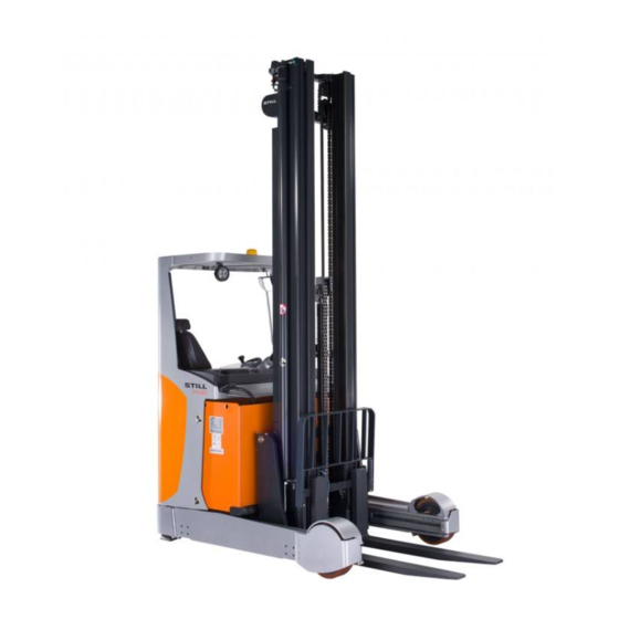
Page 56: Overview
Overviews Overview Overview Overhead guard Battery Driver’s compartment Side support (tilt protection) Lift mast Control compartment Fork arms Drive wheel Load wheel Step Battery frame 50988078001 [EN]…
-
Page 57: Overview Of The Driver’s Compartment
Overviews Overview of the driver’s compartment Overview of the driver’s compartment 2 3 4 5 Steering wheel Operating devices for hydraulic and traction Working spotlight push button (variant) functions Key switch or push button (variant) Emergency off switch Reserved Push button for additional hydraulic func- Electrical seat adjustment push button tions (variant)
-
Page 58: Operating Devices And Display Elements
Overviews Operating devices and display elements Operating devices and display elements Display and operating unit Display of the operating statuses Keypad for lift height preselection (variant) or PIN code access (variant) Keypad for onboard diagnostics, parame- terising Drive programme button (P1-P4) Blue-Q button Parking brake button Operating devices for hydraulic and…
-
Page 59: Joystick 4Plus
Overviews Operating devices and display elements Joystick 4Plus «Transition shift» slider «Transition shift/tilt centre position» push Shift button «F» (auxiliary hydraulics con- button (variant) troller) Reserve Drive direction switch Pictograms for operation of the 5th and 6th Joystick, «lifting/lowering» function hydraulic function (variant) Joystick, «shifting»…
-
Page 60: Fingertip
Overviews Operating devices and display elements Fingertip «Lift/lower» operating lever «Transition shift/tilt centre position» push «Shift» operating lever button (variant) «Tilt» operating lever Reserve «Transition shift» operating lever «Auxiliary hydraulics» push button (variant) Emergency off switch Drive direction switch «Enable» push button (variant) Signal horn button «Load measurement»…
-
Page 61: Identification Points
Overviews Identification points Identification points Overview 400-600 1000 10200 1150 9800 1110 1300 9500 1050 1200 1400 9300 1080 1240 1450 9000 1160 1320 1500 8750 1200 1600 1600 8300 1270 1700 1700 7100 X<= 15mm 50988078001 [EN]…
-
Page 62: Nameplate
Overviews Identification points Warning sign: Do not stand underneath the Decal information: Electrical seat adjust- fork/Do not stand on the fork/Danger due to ment (variant) shearing/Danger due to high fluid pressure Decal information: FEM test Decal information: Caution/read the operat- Decal information: FEM test (inspection ing instructions sticker)
-
Page 63: Production Number
Overviews Identification points Production number xx xxxx x xxxxx NOTE The production number is used to identify the truck. It can be found on the nameplate and must be referred to in all technical questions. The production number contains the following coded information: (1) Production location (2) Model…
-
Page 64
Overviews Identification points 50988078001 [EN]… -
Page 65: Operation
Operation…
-
Page 66: Checks And Tasks To Be Carried Out Prior To Commissioning
Operation Checks and tasks to be carried out prior to commissioning Checks and tasks to be carried out prior to commissioning Visual inspections WARNING Risk of accident due to damage or other defects on the truck or on the attachment (variant)! Damage to the truck or the attachment (variant) can lead to unpredictable and dangerous situations.
-
Page 67
Operation Checks and tasks to be carried out prior to commissioning cab (variant) must be undamaged and securely mounted • Attachments (variant) must be properly attached and function according to their operating instructions • All decal information signs must be in place and legible. -
Page 68: Filling The Washer System (Variant)
Operation Checks and tasks to be carried out prior to commissioning WARNING Risk of component damage! A deformed or damaged battery male connector can cause overheating and related consequential damage. – Check the battery male connector for damage. – If necessary, have the battery male connector replaced by the authorised service centre.
-
Page 69: Checking The Condition Of The Wheels And Tyres
Operation Checks and tasks to be carried out prior to commissioning Checking the condition of the wheels and tyres WARNING Risk of accident! Uneven wear reduces the stability of the truck and increases the braking distance. – If the tyres are worn or damaged, inform the authorised service centre immediately NOTE Only approved tyre types may be used;…
-
Page 70: Adjusting The Msg 65/Msg 75 Driver’s Seat
Operation Checks and tasks to be carried out prior to commissioning Adjusting the MSG 65/MSG 75 driver’s seat DANGER There is a risk of accident if the seat or seat backrest shifts suddenly, which could cause the driver to move in an uncontrolled manner. This can result in unintentional actuation of the steering or the operating devices and thus cause uncontrolled movements of the truck or load.
-
Page 71
Operation Checks and tasks to be carried out prior to commissioning Adjusting the seat backrest Do not put pressure on the seat backrest while disengaging it. – Lift the lever (2) and hold. – Push the seat backrest into the desired position. -
Page 72
Operation Checks and tasks to be carried out prior to commissioning Adjusting the lumbar support (variant) NOTE The lumbar support can be adjusted to suit the contours of the individual driver’s spine. Adjusting the lumbar support moves a convex support cushion into the upper or lower part of the backrest. -
Page 73: (Variant)
Operation Checks and tasks to be carried out prior to commissioning Switching the seat heater (variant) on and off NOTE The seat heater only functions if the seat contact switch is active, i.e. when the driver is sitting on the driver’s seat. –…
-
Page 74: Electrical Driver’s Compartment Adjustment (Variant)
Operation Checks and tasks to be carried out prior to commissioning Electrical driver’s compartment adjustment (variant) WARNING Risk of accident, risk of crushing The pedal plate and seat console move during adjustment. – Change settings only when the truck is at a standstill.
-
Page 75: Adjusting The Steering Column
Operation Commissioning Adjusting the steering column DANGER Risk of accident! – Ensure that the steering column is securely attached. Never adjust the steering column while driving. – Push the steering column adjustment lever (1) forwards to release the steering column lock.
-
Page 76
Operation Commissioning WARNING Risk of injury when jumping out of the truck! If the driver jumps out the truck while it is moving, he or she could fall under the truck or be crushed by an obstacle. If the driver’s clothing or jewellery (watch, ring etc.) become stuck on components, this can lead to serious injuries, e.g. -
Page 77: Shelves And Cup Holders
Operation Commissioning Shelves and cup holders WARNING Objects may fall into the footwell and obstruct the pedals, which poses a risk of accident! Objects to be stored must be of the correct size so that they do not fall from the shelves (1, 4) or out of the cup holder (2).
-
Page 78: Enabling Truck Functions Using The Foot Switch And Seat Switch
Operation Commissioning Enabling truck functions using the foot switch and seat switch The foot switch and seat switch are there for safety purposes during operation of the truck. The complete range of truck functions is available only when the driver is sitting on the driver’s seat and then actuates the foot switch.
-
Page 79
Operation Commissioning The hydraulic functions are only enabled if: • The seat switch has been actuated • The switch is functioning correctly The drive function is only enabled if: • The parking brake has been released • The seat switch has been actuated but the accelerator pedals have not •… -
Page 80: Unlocking The Emergency Off Switch
Operation Commissioning Unlocking the emergency off switch Unlocking the emergency off switch – Pull the emergency off switch (1) upwards until it is unlocked. Switching on the key switch WARNING Before switching on the key switch, all tests prior to commissioning must be performed without any defects being detected.
-
Page 81
Operation Commissioning – Insert switch key (1) into the key switch and turn to position «I». This initiates a self-test. All symbols on the display and operating unit are displayed briefly until the truck controllers have started up completely. When the truck is switched on, the fork carriage and the reach carriage must initially be in the basic position. -
Page 82
Operation Commissioning Displays after the switch-on process (for trucks with default options) NOTE Depending on the truck equipment, further information may be visible on the display and operating unit. Battery charge(1) The usable battery charge is shown in the display field. NOTE After connecting a «partially»… -
Page 83: Access Authorisation With Pin Code (Variant)
Operation Commissioning direction is only selected when the drive direction switch has been actuated once. Operating hours(3) The current value of the hour meter is shown in the display field. Drive programme(4) The current drive programme (1-4) is shown in the display field.
-
Page 84: Entering Truck Operating Data Via The Display And Operating Unit
Operation Commissioning Entering truck operating data via the display and operating unit Authorisation levels The authorisation levels determine which operating data and functions the user can access. The higher the authorisation level, the more comprehensive the access to truck operating data. The display and operating unit is used to access operating data at three authorisation levels:…
-
Page 85
Operation Commissioning Level 3 (authorised service centre) Access: Press OK and ESC for 4 seconds and enter the password for level 3 Authorisations: Maintenance interval PIN for remote data transfer via SIM card Delete error list Accessing the main menu without a password (authorisation level 1) First of all, press the OK button to open the main menu at authorisation level 1. -
Page 86
Operation Commissioning If the password is invalid, a corresponding message appears on the display and operat- ing unit. PASSWORD NOT VALID The message appears for three seconds and then the display and operating unit shows the input screen for the password again. The password can be entered again. -
Page 87
Operation Commissioning Entering operating data in the main menu The menus on the display and operating unit are controlled using the OK button (1), ESC button (3) and arrow buttons (2). – Press the arrow buttons to navigate through the menus –… -
Page 88
Operation Commissioning Authori- sation Main menu Submenu (level) Edit/select Comment CONFIGU- RATION VX.XX UNITS DISTANCE miles LOAD ERROR CUSTOMER MODE LIST SERVICE A–Z, *: all DEVICE devices current error TYPE since reset since deletion Error e.g. X XX XX 12 12 Teach-in ADJUST Lift heights… -
Page 89: Operating The Signal Horn
Operation Commissioning Operating the signal horn NOTE The signal horn is used to warn people against imminent danger or to announce your intention to overtake. – Push the signal horn button (1). The signal horn sounds. Checking the brake system for correct function DANGER If the brake system fails, the truck will be braked…
-
Page 90
Operation Commissioning Checking the reverse brake – Accelerate the truck without a load in a clear area; see «Driving» chapter. – Change the drive direction in inching mode; see the chapter entitled «Selecting the drive direction». The braking and subsequent acceleration processes in the opposite direction must be gentle and not subject to jerking movements. -
Page 91: Checking The Steering System For Correct Function
Operation Commissioning Checking the steering system for correct function – Operate the steering wheel (1). The steer- ing must be continuous and move freely. NOTE In the «180° steering» variant, the drive’s maximum steering angle is ±90°. 5060_003-031 Checking the emergency off function –…
-
Page 92: Checking The «Automatic Tilting Centre Position» (Variant) For Correct Function
Operation Commissioning Checking the «automatic tilting centre position» (variant) for correct function NOTE The «automatic tilting centre position» lift mast function (variant) must be executed whenever the truck is commissioned. The driver can use the «automatic tilting centre position» function to position the tilt of the fork arms to 0°…
-
Page 93: Setting The Drive Programme
Operation Commissioning Setting the drive programme Setting The driving and braking characteristics of the drive can be set on the display and operating unit. Four different drive programmes can be set. Depending on the drive programme selected, different driving characteristics are applied in relation to the maximum speed, acceleration behaviour* and deceleration behaviour**.
-
Page 94: Optispeed — Continuously Variable Reduction In Driving Speed Or Hydraulic Functions (Variant)
DANGER The stability limits defined by the laws of physics are still in effect even when the «reduction of speed when turning» function is active. There is a risk of tipping! – Before using this function, familiarise yourself with the change to the truck’s driving and steering…
-
Page 95: Driving
Operation Driving • Cornering with an inadequately secured load. • Cornering too fast on a smooth or wet roadway. Reduction in speed of hydraulic functions This variant optimises the speed of the hy- draulic functions, taking the lift height and load weight into account.
-
Page 96
There is a risk of accident! – Do not use devices during travel or when hand- ling loads. – Set the volume so that warning signals can still be heard. WARNING In areas where the use of mobile phones is prohi- bited, it is absolutely not permitted to use a mobile phone or radio telephone. -
Page 97
Operation Driving Visibility when driving The driver must look in the drive direction and have a sufficient view of the driving lane. In a reach truck, the driver’s visibility may be restricted by the lift mast or the load in particular. -
Page 98: Roadways
Max. permissible gradient in With load Without load FM-X 10, FM-X 12, FM-X 14, FM-X 17, FM-X 20, FM-X 25 FM-X 10N, FM-X 12N, FM-X 14N, FM-X 17N, FM-X 20N Picking up a load, putting down a load, stack- ing or unstacking is only permitted on a hori- zontal, level surface.
-
Page 99
Operation Driving designed for this purpose. However, movable parts may project beyond the truck contour and be damaged or torn off. Examples of such components include: • Extended lift mast • Additional attachments (mirrors, monitors etc. ) • Cab doors Condition of the roadways Roadways must be sufficiently firm, smooth and even. -
Page 100: Side Chassis Supports
Operation Driving Side chassis supports Side chassis supports (1) on the rear left and right of the truck support the truck if it tips to the side. The permissible distance «X» for the ground clearance of the chassis supports (2) is noted on the load capacity diagram on the truck.
-
Page 101: Selecting The Drive Direction
Operation Driving • Fingertip; see the chapter entitled Actuating the drive direction switch, fingertip. NOTE The drive direction can also be changed during travel. Your foot can remain on the accelerator pedal. The truck decelerates and is then accelerated again in the opposite direction (reversing).
-
Page 102: Actuating The Drive Direction Switch, Joystick 4Plus
Operation Driving Actuating the drive direction switch, joystick 4Plus – For «travelling in the load direction», press the drive direction switch (1)up. – For «travelling in the drive direction», press the drive direction switch (1)down. Actuating the drive direction switch, fingertip –…
-
Page 103
Operation Driving Observe the information in the chapter entitled «Safety regulations when driving». The driver’s seat is equipped with a seat switch. In the event of an operating error or malfunction, see the chapter entitled «Enabling truck functions using the foot switch and seat switch». -
Page 104: Starting Drive Mode, Dual-Pedal Version (Variant)
The truck cannot be driven again until the accelerator pedal has been released and then actuated again. If the truck still cannot be operated, park it securely and contact your authorised service centre. Starting drive mode, dual-pedal…
-
Page 105
Operation Driving – To «travel in the load direction», press the right-hand accelerator pedal (1). – To «travel in the drive direction», press the left-hand accelerator pedal (2). NOTE In the dual pedal version, any drive direction switches on the operating devices will not function. -
Page 106: Operating The Service Brake
The truck cannot be driven again until the accelerator pedal has been released and then actuated again, provided that the electrical fault has been corrected. If the truck still cannot be operated, park it securely and contact your authorised service centre.
-
Page 107: Applying The Electromagnetic Parking Brake
Operation Driving DANGER At speeds that are too high, there is a danger that the truck could slip or overturn! The braking distance of the truck depends on the weather conditions and the level of contamination on the roadway. – Adapt your driving and braking style to suit the weather conditions and the level of contamina- tion on the roadway.
-
Page 108
Operation Driving Functions of the parking brake when the truck is at a standstill Actuation by the driver – Push the push button (1) to apply the parking brake. The parking brake is applied audibly and the symbol (2) is shown on the display and operating unit. -
Page 109
Operation Driving Releasing the parking brake by pushing the button When the truck is ready for operation, the driver can release the parking brake at any time by pushing the button. – Sit down on the driver’s seat. – Push the push button (1) to release the parking brake. -
Page 110: Steering
Operation Driving – Push the push button (1) to apply the parking brake. The parking brake is applied immediately and audibly, and brings the truck to a standstill. The symbol (2) is shown in the display and operating unit. Actuation triggered automatically Cause Effect The parking brake is…
-
Page 111
Operation Driving 360° steering (standard) The steering wheel has no mechanical stops and can be continuously turned. Starting in the straight-ahead position, the steered wheel reaches the 90° position after 2, 2½ or 3 revolutions (can be configured) of the steering wheel. This position corresponds to the truck’s smallest turning radius. -
Page 112: Lifting
Operation Lifting Reverse steering (variant) If the steering wheel is turned clockwise when travelling in the load direction, the truck will move to the right. If the steering wheel is turned anticlockwise when travelling in the load direction, the truck will move to the left. Trucks with reverse steering are marked with an adhesive label (1) next to the steering wheel adjustment mechanism.
-
Page 113: Automatic Lift Cut Out (Variant)
Operation Lifting Automatic lift cut out (variant) The automatic lift cut out (variant) means that the load cannot be lifted above a certain height. This height is predefined by a sensor on the lift mast and cannot be changed at a later date.
-
Page 114: Reach-Lower Lock (Variant)
Operation Lifting Reach-lower lock (variant) The reach-lower lock prevents the load forks from being lowered between the load wheel posts whenever the reach carriage is in the retracted position. As a result, wide loads cannot accidentally come to rest on the load wheel posts during lowering and become unstable.
-
Page 115: Automatic Centre Position (Variant)
Operation Lifting Automatic centre position (variant) Automatic transition shift centre position (variant) The driver can use the «automatic transition shift centre position» function to position the transition shift in the centre automatically. In order to do this, the push button must be pushed until the function switches off auto- matically.
-
Page 116: Lift Mast Versions
Operation Lifting Lift mast versions One of the following lift masts may be installed in the truck: Telescopic lift mast During lifting, the lift mast rises above the outer lift cylinders, bringing the fork carriage with it via the chains (fork carriage rises twice as fast as the inner lift mast).
-
Page 117: Malfunctions In Lifting Mode
Operation Lifting Malfunctions in lifting mode Incorrect extension sequence DANGER Risk of accident! With triple lift masts (variant), an incorrect extension sequence may occur, i.e. the inner lift mast may extend before the free lift has finished. As a result, the overall height is exceeded and damage can be caused when passing through entrances or in areas with low ceilings.
-
Page 118: Lifting System Operating Devices
Operation Lifting – If the fork carriage rollers are blocked in the lift mast due to contamination, lift the fork carriage until the chains are under tension again. Remove the contamination before resuming work. WARNING Risk of injury! – Observe the safety regulations for working on the lift mast, see the chapter entitled «Working at the front of the truck».
-
Page 119: Joystick 4Plus Lifting System
Operation Lifting Joystick 4Plus lifting system A / B Lowering/lifting the fork carriage E / F Transition shift (variant) C / D Tilting the lift mast (variant) G / H Shifting DANGER Reaching or climbing between moving parts of the truck (e.g.
-
Page 120
Operation Lifting In this version, the hydraulic functions are controlled using the joystick 4Plus. The pictogram (1) shows the basic hydraulic functions and how they are controlled using the joystick. The pictogram (2) shows the 3rd and 4th function and their operation. Lifting/lowering the fork carriage To lift the fork carriage: –… -
Page 121
Operation Lifting Tilting the lift mast or fork carriage (variant) Depending on the truck equipment, either the entire lift mast is tilted or just the fork carriage (fork tilt device). To tilt the lift mast backwards: – Push the rocker button (2) towards » «. -
Page 122: Fingertip Lifting System
Operation Lifting Shifting To extend the reach carriage: – Push the joystick (4) in the direction of » «. To retract the reach carriage: – Push the joystick (4) in the direction of » «. NOTE The pictograms on the base of the joystick show the direction of movement for the corresponding hydraulic function.
-
Page 123
Operation Lifting DANGER Reaching or climbing between moving parts of the truck (e.g. lift mast, sideshifts, working equipment, load carrying devices etc.) can lead to serious injury or death and is therefore prohibited. – Always observe the safety regulations for hand- ling loads;… -
Page 124: Load Backrest (Variant)
Operation Lifting – Push the «transition shift» operating lever (4) forwards. Transition shift to the right: – Pull the «transition shift» operating lever (4) backwards. NOTE The pictograms on the operating levers show the direction of movement for the corresponding hydraulic function. Load backrest (variant) The load backrest (1) prevents individual packages from falling backwards when…
-
Page 125
Operation Lifting WARNING There is a risk of injury when changing the fork arms; the fork arms’ weight could cause them to fall on your legs, feet or knees. The space to the left and right of the fork is a danger area. –… -
Page 126
Operation Lifting Removal – Extend the reach carriage fully. – Select a pallet corresponding to the fork arm size. – Position the pallet to the left or right of the fork carriage. – Raise the fork carriage until the lower edges of the fork arms are approx. -
Page 127: Fork Extension (Variant)
Operation Lifting Fork extension (variant) DANGER There is a risk of being run over if the truck rolls away, and therefore a danger to life. – Do not park the truck on a gradient. – Apply the parking brake. – Change the fork extension in a separate, safe location on a level surface.
-
Page 128: Working Platforms
Operation Lifting – Remove the securing bolt from the fork extension (1). – Push the fork extension onto the fork arms until it is flush with the fork back. – Insert the securing bolts located behind the fork back fully into the fork extension. –…
-
Page 129: Handling Loads
Operation Handling loads Handling loads Safety regulations when handing loads The safety regulations for handling loads are shown in the following sections. DANGER There is a risk to life caused by falling loads or if parts of the truck are being lowered. –…
-
Page 130
Operation Handling loads WARNING The figures show examples. Only the capacity rating plates on the truck are valid! The attachment of additional weights to increase load capacity is prohibited. DANGER Risk to life from the truck losing stability! Never exceed the maximum loads shown! These values apply to compact and homogeneous loads. -
Page 131: Picking Up Loads
Operation Handling loads mation shown on the truck and the attachment. 88 0 kg 5230 Picking up loads To make sure that the load is securely sup- ported, it must be ensured that the fork arms are sufficiently far apart and are positioned as far as possible under the load.
-
Page 132: Danger Area
Operation Handling loads of dynamic forces such as braking. A load which is otherwise resting safely on the fork arms may move forward and fall. However, If the fork arms are too long they can catch on loading units behind the load, which then fall over when the load is raised.
-
Page 133: Transporting Pallets
Operation Handling loads DANGER Risk of injury! – Do not step on the fork. DANGER Risk of injury! – Do not step under the raised forks. DANGER People may be injured in the danger area of the truck! The danger area of the truck must be completely clear of all personnel, except the driver in his normal operating position.
-
Page 134: Transporting Swinging Loads
Operation Handling loads Transporting swinging loads Before transporting swinging loads, consult the national regulatory authorities (in Ger- many, the employer’s liability insurance asso- ciations). National regulations may place restrictions on these operations. Contact the relevant authorities. DANGER Swinging loads can result in the following risks: •…
-
Page 135: Picking Up A Load
Operation Handling loads DANGER Risk of accident! When transporting hanging loads, never abruptly perform or end driving and load movements. Never drive on upward or downward gradients with a hanging load! It is not permissible to transport containers holding fluids as hanging loads. Picking up a load NOTE Loads may only be picked up and set down on…
-
Page 136
Operation Handling loads – Tilt the fork arms or lift mast until the fork arms are horizontal. – Raise the fork carriage to a position for clear entry into the pallet or load. – Release the brake. – Drive up to the racking until the truck chassis is as close as possible. -
Page 137
Operation Handling loads – Retract the reach carriage fully. – Release the brake. DANGER Risk of accident! – Beware of any people in the danger area. – Ensure that the roadway on the drive side is clear. Move backwards carefully and slowly until the load is clear of the racking. -
Page 138: Transporting Loads
Operation Handling loads – Lower the load carefully while maintaining ground clearance. Lower wider loads that do not fit between the load wheel posts only until they are not resting on the posts. – Tilt the fork tips or lift mast fully to the drive side into the driving position.
-
Page 139
Operation Handling loads DANGER The higher a load is lifted, the less stable it beco- mes. The truck can tip over or the load can fall, increasing the risk of accident! Driving with a raised load and the lift mast tilted forward is not permitted. -
Page 140: Setting Down Loads
Operation Handling loads – Never drive with a load protruding on one side or with a load shifted to the side (sideshift). The centre of gravity of the load must always be positioned on the longitudinal axis of the truck. Setting down loads DANGER Risk of accident due to changed moment of tilt!
-
Page 141
Operation Handling loads load capacity diagram must be created as the stability will be affected. Contact the authorised service centre on • this matter. – With the load lowered in accordance with regulations, approach the racking and align the load as accurately as possible. –… -
Page 142: Driving On Upward And Downward Gradients
Operation Handling loads Driving on upward and downward gradients DANGER Danger to life! On upward and downward gradients, the load must be carried facing uphill. It is only permitted to drive on upward and down- ward gradients if they are marked as traffic routes and can be used safely.
-
Page 143
Operation Handling loads Determining the total actual weight – Park the truck securely. – Determine the unit weights by reading the truck nameplate and, if necessary, the attachment (variant) nameplate and, if Type-Modèle-Typ / Serial no.-No. de série-Serien-Nr. / year-année-Baujahr necessary, by weighing the load to be lifted. -
Page 144: Working With Attachments
Fitting attachments If the truck is equipped with an integrated attachment (variant) at the factory, the specifi- cations in the STILL operating instructions for integrated attachments must be observed. If attachments are fitted at the place of use, the specifications in the operating instructions of the attachment manufacturer must be observed.
-
Page 145
Operation Working with attachments DANGER There is risk to life caused by a falling load! During installation of a clamp with integral sideshift, ensure that the clamp does not open when the sideshift is actuated. – Notify your authorised service centre before installation. -
Page 146: Releasing The Pressure From The Auxiliary Hydraulics
Operation Working with attachments Releasing the pressure from the auxiliary hydraulics Attachments must only be fitted by competent persons in accordance with the information provided by the manufacturer and supplier of the attachments. After each installation, the attachment must be checked for correct function prior to initial commissioning.
-
Page 147: General Instructions For Controlling Attachments
Operation Working with attachments DANGER When activating the valves for the purpose of depressurising the hydraulic lines, unexpected hydraulic movements may occur. The «release the pressure from the hydraulics» truck function can be used to depressurise the entire hydraulic system. For example, this means that the fork may lower faster than expected when the «lowering»…
-
Page 148
Operation Working with attachments WARNING Use of attachments can give rise to additional hazards such as a change in the centre of gravity, additional danger areas etc. Attachments must only be used for their intended purpose as described in the relevant operating instructions. -
Page 149
Operation Working with attachments – Actuate the shift button «F»(1). – Move the joystick in the direction of the arrow «4» or «5». Or: – Move the vertical rocker button (6) to the left or right. NOTE The movement/action of these additional functions can be found in the operating instructions of the fitted attachment. -
Page 150
Operation Working with attachments Operating device Function of the attachment Joystick + shift Fork prong positioner: close/open button «F» Vertical rocker Fork positioner: forwards/backwards button + shift button «F» Vertical rocker Rotator: left/right button + shift button «F» Vertical rocker Clamp: close/open button + shift button «F»… -
Page 151: Controlling Attachments (Variant) With The Fingertip (5Th/6Th Hydraulic Function)
Operation Working with attachments Controlling attachments (variant) with the fingertip (5th/6th hydraulic function) The designation «5th/6th function» refers to the fact that the four operating levers control four functions, while additional functions can be controlled by switching functions. In this version, the attachments are controlled using the operating levers (1).
-
Page 152
Operation Working with attachments changed if necessary. Please contact the authorised service centre if necessary. Overview of the pictograms – Note the following attachment functions and pictograms! Function of the attachment Fork prong positioner: close/open Fork positioner: forwards/backwards Rotator: left/right Clamp: close/open Load retainer: close/open Additional fork carriage: lift/lower… -
Page 153: Operating The Clamp Locking Mechanism (Variant) With A Joystick 4Plus
Operation Working with attachments Operating the clamp locking mecha- nism (variant) with a joystick 4Plus This truck can be fitted with a clamp locking mechanism as a variant. This prevents the clamp from opening unintentionally if the operating function is inadvertently triggered. DANGER There is a risk of fatal injury from falling loads if the correct function of the clamp locking mechanism is…
-
Page 154
Operation Working with attachments The LED (4) indicating the clamp locking mechanism has been unlocked lights up and the clamp can now be opened. If the clamp locking mechanism is locked again, the LED will go out. – To open the clamp, press and hold shift button «F»… -
Page 155: Operating The Clamp Locking Mechanism (Variant) With The Fingertip Switch
Operation Working with attachments Operating the clamp locking mech- anism (variant) with the fingertip switch This truck can be fitted with a clamp locking mechanism as a variant. This prevents the clamp from opening unintentionally if the operating function is inadvertently triggered. DANGER There is a risk of fatal injury from falling loads if the correct function of the clamp locking mechanism is…
-
Page 156: Picking Up A Load Using Attachments
Operation Working with attachments The LED (4) indicating the clamp locking mechanism has been unlocked lights up and the clamp can now be opened. If the clamp locking mechanism is locked again, the LED will go out. – To open the clamp, press and hold shift button «F»…
-
Page 157: Operating Auxiliary Equipment
Operation Operating auxiliary equipment Operating auxiliary equipment Switching the working spotlights (variant) on and off There is an option to have the truck fitted with one or several working spotlights (1) to improve illumination of the working area. – Switch on the truck. –…
-
Page 158: Clipboard (Variant)
FleetManager (variant), which is in- stalled in the truck’s acceleration sensor. The acceleration sensor records data in the event of an accident. This data can be electronically read out and evaluated. For further informa- tion, contact your STILL service centre. 50988078001 [EN]…
-
Page 159: Active Load Stabilisation Als (Variant)
Even if vibration damping of the lift mast is inactive, the driver can still operate all of the truck’s hydraulic functions. – If active vibration damping fails, take the change in vibration characteristics into consideration.
-
Page 160: Camera/Monitor System (Variant)
Operation Operating auxiliary equipment Camera/monitor system (variant) CAUTION Risk of accident due to collision of the lift mast or load with the racking or low ceilings. – Also, when using the system, always consider the vibration characteristics of the lift mast and the load.
-
Page 161
Operation Operating auxiliary equipment For this reason, load measurement is disabled during the following truck activities: • Driving • Lifting • Lowering Once the fork has been in the inactive posi- tion for two seconds, load measurement is enabled. Load measurement is now possible. The measured weight of the load is shown on the display and operating unit. -
Page 162: Battery Change Frame (Variant)
Operation Battery change frame (variant) After releasing the button, the display switches back to the speed indicator after 2.5 seconds. If the button is pressed for more than two minutes, the display switches back to the speed indicator but message «A3440» also appears.
-
Page 163: Safe Handling
Operation Battery change frame (variant) Safe handling WARNING Risk of physical injury Battery racks are used for moving heavy weights. Especially for versions with manual drive, there is always the risk of being trapped or crushing hands or fingers. The greatest possible care must therefore be taken to ensure that the battery is against its stop and that when the battery moves along the guides your fingers or hands are not in the…
-
Page 164: Adjusting The Transfer Height
Operation Battery change frame (variant) a double battery rack is available, a freshly charged battery can also be carried on the second roller channel. Adjusting the transfer height – Use an external spirit level or straight-edge to check the height of the battery rack and that it is level.
-
Page 165: Battery Replacement Area
Operation Battery change frame (variant) Battery replacement area Requirements for the battery replace- ment area There must be sufficient space to allow the change frames to be positioned and for the truck to be driven through the area. The battery replacement area must be hori- zontal, level and have a sufficient load capac- ity.
-
Page 166: Lift Height Preselector (Variant)
Operation Lift height preselector (variant) CAUTION Risk of damage to property It depends on conditions on site whether or not an extension cable for connecting the battery to the truck is required during battery replacement. If an extension cable is required, only a cable with an appropriate cross-section and approved plugs must be used.
-
Page 167: Definition Of Terms
Operation Lift height preselector (variant) Definition of terms Level 1-20 Level Area A-H One target height can be assigned to each level. Valid levels can be reached semi- automatically. Area A warehouse can be divided into eight areas and each area can contain up to 20 levels. Placing into stock Placing into stock (3) is the insertion of a pallet into the rack.
-
Page 168: Auto Mode Function
Operation Lift height preselector (variant) Pallet free lift The pallet free lift (10) is the difference in height by which the load support is raised or lowered after shifting in order to place a load into stock or remove a load from stock. This value can be individually adjusted for placing into and removing from stock at each level by using the service software.
-
Page 169
Operation Lift height preselector (variant) • AUTO MODE height preselection «Without fork cycle» • AUTO MODE height preselection «Start only with fork below target height» AUTO MODE height preselection «Basic position» In the «Basic position» configuration, the assistant also specifies, in addition to the height preselection, the respective position of the reach carriage. -
Page 170
Operation Lift height preselector (variant) Once the area and level have been entered, the place into/remove from stock function must be selected to activate height preselection. • Regardless of the position of the reach car- riage, only lifting or lowering is enabled and is specified by the assistant accordingly. -
Page 171: Operating The Lift Height Preselector
NOTE If height preselection is active, only the arrow symbols for movements that are still possible will light up on the function symbols in the assistant (1). The required movement is identified in each case by a corresponding flashing arrow symbol.
-
Page 172
Operation Lift height preselector (variant) When the truck has been switched ON, area «A» (2) is automatically selected. The area can be changed by pressing the button (3). If «H» is reached, «A» is repeated. This enables area preselection. A level can be selected (1-20) by entering a digit using the alphanumeric keypad (4). -
Page 173
Operation Lift height preselector (variant) – After entering the target level (e.g. A1), press the button for placing into stock (1). The symbol for placing into stock (3) and «auto» for automatic operation (4) appear in the assistant (2). The display (5) changes from the target height to the distance to the target (target difference). -
Page 174
Operation Lift height preselector (variant) Example: Removing from stock in fully automatic mode NOTE Removing from stock can only be selected if valid heights were assigned to the levels during the teach-in process. Levels that are invalid or that have not had a height assigned to them are not activated in automatic mode. -
Page 175: Teach-In, General
Operation Lift height preselector (variant) – Activate the lift function (displayed by the assistant). The exact selected height is reached and the automatic stop is per- formed (6). The display (5) shows a dis- tance to the target ≤ 6 mm. –…
-
Page 176: Performing A Teach-In
Operation Lift height preselector (variant) This can only be done using the service software. The following parameters, among others, can be changed using the service software: • Pallet free lift height • Pallet free lowering height • Accuracy and speed of pallet free lift and pallet free lowering •…
-
Page 177
Operation Lift height preselector (variant) level, see the chapter entitled «Onboard truck configuration/General». – Press the «ESC» (4) and «OK» (6) buttons for three seconds. The following appears on the display field (1): PASSWORD _ _ _ _ – Using the enter keys (3), enter a password for authorisation level «2»… -
Page 178
Operation Lift height preselector (variant) Entering and saving lift heights for height preselection The programmable lift heights are entered using the enter keys on the control panel. The result of each entry is displayed in the display field (1). To ensure saved lift heights can be selected at a later stage, three items of information must be entered for each lift height: •… -
Page 179: Cab Operation (Variant)
Operation Cab operation (variant) Programming the lift height (example: area A, level 07, lift height 5500 mm) Display Button Action A07 05 (X flashes) XX Press, the flashing digit is —> the cursor advances one replaced place A07 055 (X flashes) X Press, the flashing digit is —>…
-
Page 180: Opening The Cab Door
Operation Cab operation (variant) Opening the cab door DANGER Risk of fatal injury as a result of driving with the cab door open! The driver can be injured if he does not keep his entire body within the protective cab, or if he falls off the truck.
-
Page 181: Closing The Cab Door
Operation Cab operation (variant) Closing the cab door DANGER Risk of fatal injury as a result of driving with the cab door open! The driver can be injured if he does not keep his entire body within the protective cab, or if he falls off the truck.
-
Page 182: Cab Operating Devices
Operation Cab operation (variant) – Pull both locking knobs (1) upwards until the window (2) can be opened outwards. – Ensure that the surrounding area is safe, push the window outwards and climb out of the truck to the side. –…
-
Page 183: Cab Interior Lighting (Variant)
Operation Cab operation (variant) Operating device Function Heating system rocker Selection of two heating levels for the warm air heating system switch (door), 2-stage in the door Ventilation fan rocker Selection of two blower speeds switch, 2-stage Heating system rocker Selection of two heating levels for the warm air heating system switch (footwell), 2-stage under the steering wheel…
-
Page 184: Heating System In The Cab (Variant)
Operation Cab operation (variant) Heating system in the cab (variant) Switching on the blower and heating system DANGER There is a risk of poisoning if heavily polluted surrounding air is aspirated into the closed cab! The heater must not be operated in the vicinity of storage areas or the like, in which fuel vapours or fine dust (e.g.
-
Page 185: Cold Store Application
Operation Cold store application – Switch on the desired heating function by actuating the relevant rocker switch; see the chapter entitled «Cab operating devices». Switching off the heating system and blower DANGER The heating system overheats if the hot air cannot escape from it. There is a risk of fire! The blower may only be turned off if the heating system is turned off.
-
Page 186: Areas Of Application
Operation Cold store application Areas of application Distinction is drawn between 4 different areas of application, and between various different modes of operation within these areas: Area of Cold store Temperature Operating time Comment application equipment range up to Not required Typical -10°C Brief…
-
Page 187: Battery In The Cold Store
Operation Cold store application Battery in the cold store The drive batteries of the industrial trucks may under no circumstances reach the temperature of the cold store (-30°C) or shock cold store (-42°C). This means that they must either be in operation or charging. The batteries must not remain in the cold store overnight without power drain or charging.
-
Page 188: Warming Up The Truck
Operation Operating the display and operating unit order to keep the most important compo- nents at operating temperature. • Precautions are taken to allow any conden- sation water to drain off without it getting into the electrics. • The lift cylinders and other hydraulic parts are fitted with special seals where required.
-
Page 189
Operation Operating the display and operating unit Item no. Display Comment Battery charging state Steering angle display combined with drive direction Time display (digital) Joystick 4Plus (operating error) Display is dependent on truck parameters (e.g. driving speed, reach position, lift Multifunction indicator height) Display field for the selected default setting… -
Page 190: Blue-Q Efficiency Mode
Operation Blue-Q efficiency mode Item no. Display Comment Battery water level display too low (variant) — Battery not locked Blue-Q efficiency mode Functional description The Blue-Q efficiency mode affects both the drive unit and the activation of the additional consumers, and reduces the truck’s energy consumption.
-
Page 191: Fault Displays
Operation Fault displays Fault displays View on the display and operating unit Error messages Malfunctions are indicated by error numbers on the display (2). In addition to the error message, symbol (1) lights up. NOTE If the error cannot be rectified by switching on and off or by operating the truck correctly, please call the authorised service centre.
-
Page 192
Operation Operating in special operating situations Determining the total actual weight – Park the truck securely; see the chapter entitled «Parking the truck securely». – Determine the unit weights by reading the truck nameplate and, if necessary, the Type-Modèle-Typ / Serial no.-No. de série-Serien-Nr. / year-année-Baujahr attachment (variant) nameplate. -
Page 193
Operation Operating in special operating situations Lashing down the truck CAUTION Abrasive lashing straps can rub against the surface of the truck and cause damage. – Position slip-resistant pads underneath the lifting points (3) (e.g. rubber mats or foam). DANGER The load may slip if the lashing straps slide off! The truck must be lashed securely so that it cannot move during transportation. -
Page 194: Towing
Operation Operating in special operating situations Towing DANGER The brake system on the towing vehicle may fail. There is a risk of accident! If the brake system of the towing vehicle is not adequately sized, the vehicle may not brake safely or the brakes may fail.
-
Page 195
– Only manoeuvre with a guide. If the truck’s steering still functions and the brake is released, the truck can be towed with ropes. – Select a towing speed that allows the truck and towing vehicle to be braked and controlled effectively at all times. -
Page 196: Crane Loading
Operation Operating in special operating situations the heavy-duty rollers must be placed under- neath the drive wheel or underneath the posts on the side of the truck. As the drive wheel does not come into contact with the ground when using this towing method, the brakes can also no longer operate.
-
Page 197
Operation Operating in special operating situations Hooking on the lifting straps CAUTION Harnesses may damage the truck’s paintwork! Harnesses may damage paintwork by rubbing and pressing on the surface of the truck. Particularly hard or sharp-edged harnesses, such as wires or chains, can quickly damage the surface. -
Page 198
Operation Operating in special operating situations Hooking on the lifting straps to a truck without a lift mast • Attach two suitable shackles (4) in the upper mast bearings of the truck • Guide the lifting strap upwards through the two shackles and through the struts of the overhead guard. -
Page 199: Procedure In Emergencies
Operation Procedure in emergencies Loading the truck DANGER If the raised truck swings in an uncontrolled manner, it may crush people. There is a risk of fatal injury! – Never walk or stand underneath suspended loads. – Do not allow the truck to bump into anything whilst it is being lifted, or allow it to move in an uncontrolled manner.
-
Page 200: Emergency Shutdown
Operation Procedure in emergencies connector is disconnected. – Do not disconnect the battery male connector while the truck is switched on except in the case of an emergency. CAUTION Risk of accident in the event of an emergency shutdown of the truck whilst the load is raised. In the event of an emergency shutdown of the truck whilst the load is raised, the fork carriage must be fully lowered once and the reach carriage fully…
-
Page 201: Procedure If Truck Tips Over
Operation Procedure in emergencies Procedure if truck tips over DANGER If the truck tips over, the driver could fall out and slide under the truck with potentially fatal conse- quences. There is a risk to life. Failure to comply with the limits specified in these operating instructions, e.g.
-
Page 202: Emergency Lowering
Operation Handling the battery In the event of a power failure, the forks can be lowered manually so that the truck can be moved to a safe position. The emergency lowering valve is operated remotely by means of a flexible drive. The handle for operation is located on the reach carriage near the mast fixture.
-
Page 203
Operation Handling the battery DANGER Risk of accident! The battery could fall from the lifting accessory, or the lifting accessory could tip over or become damaged. If this happens, there is a risk to life. The battery must be removed only when the truck is on level, smooth ground with sufficient load capacity. -
Page 204
Operation Handling the battery WARNING DANGER The battery is very heavy. There is a risk of serious injury if any parts of the body remain under the battery. There is a risk of crushing/shearing! – Always wear safety footwear during battery replacement. Fire protection measures DANGER No flammable materials or spark-… -
Page 205
Operation Handling the battery Maintaining the battery The cell covers of the battery must be kept dry and clean. Any spilt battery acid must be neutralised immediately. Observe the safety regulations for handling battery acid; see the chapter entitled «Battery acid». Terminals and cable shoes must be clean, lightly coated with battery grease and screwed on tightly. -
Page 206: General Information On Battery Replacement
Operation Handling the battery Damage to cables CAUTION There is a risk of short circuit if the cables are damaged. – Check the connecting cable for damage. – When removing and reinstalling the battery, ensure that the battery cables are not damaged. General information on battery replacement CAUTION…
-
Page 207: Actuating The Battery Lock
Operation Handling the battery The battery can be removed using the follo- wing lifting accessories: • Crane (with standard equipment) • Change frame (with roller channel variant for side battery replacement) The load capacity of the lifting accessory used must at least match the battery weight (see battery identification plate).
-
Page 208
Operation Handling the battery – Move the actuating lever into the zero position once – Actuate the actuating lever again and retract the reach carriage to the drive side into the end position – Pull the release lever (3) for the battery lock upwards The battery is unlocked and can be extended to the load side together with the reach… -
Page 209: Disconnecting The Battery Male Connector
Operation Handling the battery NOTE If the acoustic warning signal sounds again and the «creep speed» symbol reappears, the battery was not extended to the load side by at least one third of the reach travel once it was unlocked. Extend and retract the battery again to lock the battery.
-
Page 210: Battery Replacement Using A Crane
Operation Handling the battery – Disconnect the battery male connector (1) from the plug connection by pulling in the direction of the arrow. – Place the battery male connector on the battery. CAUTION There is a risk of short circuit if the cables are damaged.
-
Page 211
Operation Handling the battery The battery sits in a frame. To replace the battery, this frame is extended in the load direction together with the reach carriage. Before the reach carriage is extended, the battery lock lever must be actuated. When the reach carriage is fully retracted, the battery frame is mechanically locked again. -
Page 212
Operation Handling the battery – Extend the reach carriage fully together with the battery (2). – Switch off the truck. – Push the emergency off switch. CAUTION Risk of component damage! If you remove the battery male connector while the truck is switched on (under load), an arc will be produced. -
Page 213
Operation Handling the battery Installing the battery WARNING Risk of corrosion The electrolyte (battery acid) is toxic and corrosive on contact. When handling battery acid, the speci- fied safety measures must be observed without fail. For newly charged batteries in particular, be aware of the risk of explosion in the gassing area. -
Page 214
Operation Handling the battery – Return the hexagon key for the emergency lowering mechanism to its position in the driver’s compartment underneath the steering wheel. Activities after installation of the battery DANGER If the battery is not locked correctly, the battery can slide out of the truck, with potentially fatal consequences! –… -
Page 215: Changing The Battery Using The Internal Roller Channel (Variant)
Operation Handling the battery – Make sure that the battery cable cannot become trapped when the reach carriage is retracted with the battery. – Unlock the emergency off switch. – Switch on the truck. – Press the foot switch. – Retract the reach carriage with the battery fully until the battery lock engages.
-
Page 216
Operation Handling the battery WARNING Risk of crushing if the battery falls out. Releasing the battery lock, as described below, must only be carried out on horizontal, level ground using a suitable battery change frame. The battery lock lever may be actuated only when the truck is stationary and the reach carriage is fully retracted. -
Page 217
Operation Handling the battery – Position the truck and battery rack parallel to each other. – Position the truck and the battery rack so that the roller channels of the truck and battery rack are exactly aligned with each other. Extending the battery The battery sits in a frame. -
Page 218
Operation Handling the battery – Disconnect the battery male connector (3). CAUTION There is a risk of short circuit if the cables are damaged! Position the battery cable on the battery in such a way that it cannot be crushed when removing or inserting the battery. -
Page 219
Operation Handling the battery – Swing the swing bolt (2) up to the stop (3). DANGER The battery can now move freely and may roll away unimpeded, creating a risk of crushing! People must not stand directly in the battery’s direction of travel. -
Page 220
Operation Handling the battery CAUTION Risk of component damage! If you connect the battery male connector when the truck is switched on (under load), an arc will be produced. This can cause the contacts to erode, which considerably shortens their service life. –… -
Page 221: Battery Commissioning
Operation Handling the battery Battery commissioning CAUTION battery, as it has had to be transported over a long distance (e.g. from overseas). Please Risk of accident, risk of injury from crushing and follow the information and guidelines from the shear points battery manufacturer precisely.
-
Page 222
This is achieved by placing suitable washers beneath rubber buffers (2) on the load side. If the lock still does not function properly despite all of these adjustment options, check whether the correct reach cylinder has been… -
Page 223: Setting The Battery Data
Operation Handling the battery Setting the battery data Adjustment instructions To enable the truck controller to determine the residual capacity of the battery correctly, the technical data for the installed battery must be entered using the following buttons on the display: –…
-
Page 224
Operation Handling the battery – Push the arrow buttons on the keypad (2) to select. Once the correct value is set, confirm by pushing the «OK» button on the keypad (2). – The capacity is read from the nameplate on the battery and is input as a column of numbers. -
Page 225: Battery Transport With Crane
Operation Handling the battery Battery transport with crane DANGER If the load is dropped, the conse- quences could potentially be fatal! Type-Modèle-Typ / Serial no.-No. de série-Serien-Nr. / year-année-Baujahr – Never walk or stand underneath Rated capacity Unladen mass suspended loads. Capacité…
-
Page 226: Maintaining The Battery
Operation Handling the battery Maintaining the battery DANGER Risk of explosion! – Observe the safety regulations when handling the battery; see the chapter entitled «Safety regulations when handling the battery». DANGER Risk of accident! If the battery has to be removed for maintenance, this must only be carried out using the specified de- vices;…
-
Page 227
Operation Handling the battery after another. If the permissible discharge depth of 20% residual capacity is reached, only the last segment will still flash. This indicates that the lift cut out has been reached. After connecting a partially charged battery: •… -
Page 228
Operation Handling the battery – Fully extend the battery together with the reach carriage to the load side before charging the battery in the truck (see the chapter entitled «Changing the battery») CAUTION Risk of component damage! If you remove the battery male connector while the truck is switched on (under load), an arc will be produced. -
Page 229
Operation Handling the battery – Before the charging process, inspect the battery cable and charging cable for damage and change if necessary. CAUTION Risk of component damage! If you connect the battery male connector while the battery charger is switched on (under load), an arc will be produced. -
Page 230: Decommissioning
Operation Decommissioning – Reconnect the battery male connector to the truck; see the chapter entitled «Con- necting the battery male connector». – Fully retract the battery together with the reach carriage to the drive side (see the chapter entitled «Changing the battery») Decommissioning Parking the truck securely DANGER…
-
Page 231
Operation Decommissioning – Lower the fork to the ground. – Tilt the lift mast forwards until the tips of the fork arms rest on the ground. – If attachments (variant) are fitted, retract the working cylinders. – Turn the switch key (variant) to the left and pull it out. -
Page 232: Shutting Down And Storing The Truck
Operation Decommissioning Shutting down and storing the truck CAUTION Component damage due to incorrect storage! If the truck is stored or shut down in an improper manner for more than two months, it may suffer cor- rosion damage. If the truck is parked in an ambient temperature of below -10°C for an extended period, the batteries will cool down.
-
Page 233: Re-Commissioning After Shutdown
Operation Decommissioning NOTE Only store batteries that are fully charged. – Spray all exposed electrical contacts with a suitable contact spray. CAUTION Danger of tyre deformation by continuously loading on one side! Jack up the truck so that all wheels are off the ground.
-
Page 234: Cleaning
Operation Cleaning – Carry out checks and operations before the first commissioning. – Change the brake fluid. – Put the truck into operation. During commissioning, the following must be checked in particular: • Drive, controller, steering • Brakes (service brake, parking brake) •…
-
Page 235: Cleaning Load Chains
Operation Cleaning – Use equipment such as stepladders or platforms to reach inaccessible areas Cleaning the truck exterior – Clean the truck exterior using water-soluble cleaning materials and water (sponge, cloth) – Clean all accessible areas, the oil filling openings and their surroundings, and clean the lubricating nipples before lubricating NOTE The more often the truck is cleaned, the more…
-
Page 236: After Cleaning
Operation Cleaning After cleaning – Carefully dry the truck (e.g. with com- pressed air). – Sit in the driver’s seat and start up the truck in accordance with the regulations. CAUTION Risk of short circuit! – If any moisture has penetrated the motors despite the precautionary measures taken, first dry them using compressed air.
-
Page 237: Maintenance
Maintenance…
-
Page 238: General Maintenance Information
Maintenance General maintenance information General maintenance information Personnel qualifications Only qualified and authorised personnel are allowed to perform maintenance work. The annual testing must be carried out by a qualified person. The examination and assessment by the qualified person must not be affected by operational and economic conditions and must be conducted solely from a safety perspective.
-
Page 239
Maintenance General maintenance information vides optimal performance and service life. It is also a precondition for any warranty claims. Maintenance timeframe – The maintenance check lists indicate the maintenance work that is due. – Carry out maintenance work on the truck based on the hour meter. -
Page 240
Maintenance General maintenance information 50988078001 [EN]… -
Page 241: Maintenance — 1000 Hours/Year
Maintenance General maintenance information Maintenance — 1000 hours/year At operating hours Carried 1000 2000 4000 5000 7000 8000 10000 11000 13000 14000 Chassis, bodywork and fittings Examine the chassis, covers, support elements and mast mounting for cracks or damage (visual inspection) Check the overhead guard/cab and panes of glass for damage;…
-
Page 242
Maintenance General maintenance information At operating hours Carried 1000 2000 4000 5000 7000 8000 10000 11000 13000 14000 Check the steering turntable bearing for ease of movement and wear Check the steering gears for play, and lubricate Hydraulic brake system Check the condition of all mechanical and hydraulic brake parts, check for correct function and clean Check the brake linings and replace if necessary… -
Page 243
Maintenance General maintenance information At operating hours Carried 1000 2000 4000 5000 7000 8000 10000 11000 13000 14000 Measure the battery voltage under load Perform insulation testing Measure the tray for short circuits Hydraulic system Check the condition of the hydraulic system and check for damage, correct function and leak tightness Check the hydraulic pump for leak tightness Check the hydraulic oil level… -
Page 244
Maintenance General maintenance information At operating hours Carried 1000 2000 4000 5000 7000 8000 10000 11000 13000 14000 Check the attachments for wear and damage; observe the manufacturer’s mainten- ance instructions Clean excessive dirt from the battery change frame and check it for deformation/da- mage Check the freedom of movement of the rollers and keep the surface of the rollers free of corrosion using a film of oil Lubricating… -
Page 245: Maintenance — 3000 Hours/Every Two Years
Maintenance General maintenance information Maintenance — 3000 hours/every two years Carried At operating hours 3000 6000 9000 12000 15000 Chassis, bodywork and fittings Examine the chassis, covers, support elements and mast mounting for cracks or damage (visual inspection) Check the overhead guard/cab and panes of glass for damage;…
-
Page 246
Maintenance General maintenance information Carried At operating hours 3000 6000 9000 12000 15000 Check that the steering wheel is securely attached and check the turning handle for damage Check the function of the steering system Check the steering turntable bearing for ease of movement and wear Check the steering gears for play, and lubricate Hydraulic brake system Check the condition of all mechanical and hydraulic brake parts, check for correct… -
Page 247
Maintenance General maintenance information Carried At operating hours 3000 6000 9000 12000 15000 Check the battery for damage and acid density; observe the manufacturer’s mai- ntenance instructions Check the battery male connector and cables for damage Measure the battery voltage under load Perform insulation testing Measure the tray for short circuits Hydraulic system… -
Page 248: Additional Maintenance Guidelines For Using The Truck In A Cold Store — 500 Hours Or Every 12 Weeks
Maintenance General maintenance information Carried At operating hours 3000 6000 9000 12000 15000 Special equipment Check the heating system for damage; observe the manufacturer’s maintenance instructions Check the attachments for wear and damage; observe the manufacturer’s mainten- ance instructions Clean excessive dirt from the battery change frame and check it for deformation/da- mage Check the freedom of movement of the rollers and keep the surface of the rollers free of corrosion using a film of oil…
-
Page 249: Ordering Spare Parts And Wearing Parts
Maintenance General maintenance information At operating hours Carried 1000 1500 2000 2500 3000 3500 4000 4500 Perform a visual inspection of the fork arms Check the ease of movement of the limit switches Lubricating Lubricate using approved lubricants in accordance with the lubrication plan In addition, lubricate the lubricating nipple for the door hinges and the door closing mechanism every six weeks Ordering spare parts and wearing…
-
Page 250: Maintenance Data Table
Maintenance General maintenance information When topping up working materials, use only clean containers! Maintenance data table CAUTION Risk of damage to property Trucks for cold store operation must be lubricated using different lubricants; see the chapter entitled «Cold store application». Additive/consum- Specifications Unit…
-
Page 251
Maintenance General maintenance information Additive/consum- Specifications Unit Measurement able As required Lift mast Super-pressure SKD 3400 adhesive lubricant ID no. 0147873 Load chains Chain lubrication Stabylan 2100 As required ID no. 8010100 — Setting Distance to support 35 mm under the top roller edge of the inner mast Brake system… -
Page 252: Safety Regulations For Maintenance
Maintenance Safety regulations for maintenance Safety regulations for maintenance General information To prevent accidents during maintenance and repair work, all necessary safety measures must be taken, e.g.: • Ensuring that unintentional movement or undesired start-up of the truck is prevented (by applying the parking brake, having the truck jacked up by the authorised service centre).
-
Page 253: Safety Devices
Maintenance Safety regulations for maintenance Safety devices After maintenance and repair work, all safety devices must be reinstalled and tested for operational reliability. Set values The device-dependent set values must be observed when making repairs and when changing hydraulic and electrical compo- nents.
-
Page 254
Maintenance Safety regulations for maintenance DANGER Risk of accident! – Use only chains with adequate lifting capacity to secure the particular lift mast. CAUTION Potential damage to the ceiling! – Note the maximum lift height of the lift mast. Removing the lift mast DANGER Risk of accident! –… -
Page 255: Servicing
Maintenance Servicing Securing the triple mast – Extend the lift mast. – Route the chain over the cross beam of the outer mast (1) and under the cross beam of the middle mast (2). – Lower the lift mast until it strikes the chain. –…
-
Page 256: Maintaining Wheels And Tyres
Maintenance Servicing – Open filler cap (1) and check the acid level. For batteries with «caged cell plugs», the acid must reach the bottom of the cage; for batteries without «caged cell plugs», it must cover the lead plates by about 10–15 mm. –…
-
Page 257
Maintenance Servicing Checking the condition and wear of the tyres WARNING Tyre quality affects the stability and handling of the truck. Changes must only be made following consultation with the manufacturer. When changing wheels or tyres, ensure that this does not cause the truck to tilt to one side (e.g. always replace right-hand and left-hand wheels at the same time). -
Page 258: Checking The Hydraulic System For Leaks
Maintenance Servicing Checking the hydraulic system for leaks WARNING Hydraulic oil under pressure can escape from leaking lines and cause injuries to the skin. Wear suitable protective gloves, industrial goggles etc. WARNING Hydraulic hoses become brittle over time! Hydraulic hoses must not be used for a period longer than six years.
-
Page 259: Greasing The Lift Mast And Roller Tracks
Maintenance Servicing Greasing the lift mast and roller tracks – Remove dirt and lubricant residue from the roller tracks – Lubricate the roller tracks (1) of the outer mast, middle mast and inner mast with a super-pressure adhesive lubricant to reduce wear;…
-
Page 260
Maintenance Servicing 50988078001 [EN]… -
Page 261: Technical Data
Technical data…
-
Page 262: Dimensions
Technical data Dimensions Dimensions Measurements h and b customised and can be taken from the order confirmation. 50988078001 [EN]…
-
Page 263: Vdi Datasheet Fm-X 10 (N), Fm-X 12 (N)
Technical data VDI datasheet FM-X 10 (N), FM-X 12 (N)* VDI datasheet FM-X 10 (N), FM-X 12 (N)* *Subject to change DS = drive side LS = load side All dimensions include sideshift/fork tilt; mast sideshift not possible. Decreases for larger batteries by 90 mm in each case depending on battery size…
-
Page 264
Technical data VDI datasheet FM-X 10 (N), FM-X 12 (N)* Wheels, chassis frame FM-X 12 FM-X 10 FM-X 10 N FM-X 12 3.1 Tyres Polyureth. Polyureth. Polyureth. Polyureth. Ø 360 x Ø 360 x Ø 360 x 3.2 Front tyre size mm Ø… -
Page 265
Technical data VDI datasheet FM-X 10 (N), FM-X 12 (N)* FM-X 12 FM-X 10 FM-X 10 N FM-X 12 Ground clearance with 4.31 load under lift mast Ground clearance at 4.32 centre of wheelbase Working width when handling pallets 4.34.1… -
Page 266
Technical data VDI datasheet FM-X 10 (N), FM-X 12 (N)* Electric motor FM-X 12 FM-X 10 FM-X 10 N FM-X 12 Traction motor, power rating, S2=60 min. Lift motor, power rating, S3=15% Battery in accordance with DIN 43531/35/36 A, 43531C /… -
Page 267: Vdi Datasheet Fm-X 14 (N), Fm-X 17 (N)
Technical data VDI datasheet FM-X 14 (N), FM-X 17 (N)* VDI datasheet FM-X 14 (N), FM-X 17 (N)* *Subject to change DS = drive side LS = load side All dimensions include sideshift/fork tilt; mast sideshift not possible. Decreases for larger batteries by 90 mm in each case depending on battery size…
-
Page 268
Technical data VDI datasheet FM-X 14 (N), FM-X 17 (N)* Wheels, chassis frame FM-X 17 FM-X 14 FM-X 14 N FM-X 17 3.1 Tyres Polyureth. Polyureth. Polyureth. Polyureth. Ø 360 x Ø 360 x Ø 360 x 3.2 Front tyre size mm Ø… -
Page 269
Technical data VDI datasheet FM-X 14 (N), FM-X 17 (N)* FM-X 17 FM-X 14 FM-X 14 N FM-X 17 Ground clearance with 4.31 load under lift mast Ground clearance at 4.32 centre of wheelbase Working width when handling pallets 4.34.1… -
Page 270
Technical data VDI datasheet FM-X 14 (N), FM-X 17 (N)* Electric motor FM-X 17 FM-X 14 FM-X 14 N FM-X 17 Traction motor, power rating, S2=60 min. Lift motor, power rating, S3=15% Battery in accordance with DIN 43531/35/36 A, 43531C /… -
Page 271: Vdi Datasheet Fm-X 20 (N, W, Ew)
Technical data VDI datasheet FM-X 20 (N, W, EW)* VDI datasheet FM-X 20 (N, W, EW)* *Subject to change DS = drive side LS = load side All dimensions include sideshift/fork tilt; mast sideshift not possible. Decreases for larger batteries by 90 mm in each case depending on battery size…
-
Page 272
Technical data VDI datasheet FM-X 20 (N, W, EW)* Wheels, chassis frame FM-X 20 FM-X 20 FM-X 20 FM-X 20 N 3.1 Tyres Polyureth. Polyureth. Polyureth. Polyureth. Ø 360 x Ø 360 x Ø 360 x 3.2 Front tyre size mm Ø… -
Page 273
Technical data VDI datasheet FM-X 20 (N, W, EW)* FM-X 20 FM-X 20 FM-X 20 FM-X 20 N Ground clearance with 4.31 load under lift mast Ground clearance at 4.32 centre of wheelbase Working width when handling pallets 4.34.1 measuring 1000×1200… -
Page 274: Vdi Datasheet Fm-X 22
Technical data VDI datasheet FM-X 22* Electric motor FM-X 20 FM-X 20 FM-X 20 FM-X 20 N Traction motor, power rating, S2=60 min. Lift motor, power rating, S3=15% Battery in accordance with DIN 43531/35/36 A, 43531C / 43531B / 43531C /…
-
Page 275
Technical data VDI datasheet FM-X 22* All dimensions include sideshift/fork tilt; mast sideshift not possible. Decreases for larger batteries by 90 mm in each case depending on battery size Calculation in accordance with VDI 3597; extended for larger batteries by 90 mm in each case depending on battery size Dependent on the lift mast;… -
Page 276
Technical data VDI datasheet FM-X 22* Basic dimensions FM-X 22 Lift mast/fork carriage tilt, forwards/back- a/b (°) ° wards Height with lift mast retracted 5200 Free lift 4578 Lift 12,500 Height with lift mast extended 13,122 Height of overhead guard (cab) -
Page 277
Technical data VDI datasheet FM-X 22* Performance data FM-X 22 Driving speed with/without load km/h 14/14 Driving speed with/without load when 5.11 km/h reversing 14/14 Lifting speed with/without load 0.34/0.50 Lowering speed with/without load 0.52/0.50 Reach speed with/without load 0.18… -
Page 278
Technical data VDI datasheet FM-X 22* FM-X 22 Distributed load in accordance with VDI kg/m2 2199 50988078001 [EN]… -
Page 279: Vdi Datasheet Fm-X 25
Technical data VDI datasheet FM-X 25* VDI datasheet FM-X 25* *Subject to change DS = drive side LS = load side All dimensions include sideshift/fork tilt; mast sideshift not possible. Decreases for larger batteries by 90 mm in each case depending on battery size…
-
Page 280
Technical data VDI datasheet FM-X 25* Wheels, chassis frame FM-X 25 Tyres Polyureth. Front tyre size Ø 360 x 140 Rear tyre size Ø 350 x 100 Number of wheels at front/rear (× = driven) 1x/2 Rear track width 1167… -
Page 281
Technical data VDI datasheet FM-X 25* FM-X 25 Turning radius 4.35 1915 Length across the load wheel supports 4.37 2066 Step height 4.43 Performance data FM-X 25 Driving speed with/without load km/h 14/14 Driving speed with/without load when km/h 5.11… -
Page 282: Wheels And Tyres
FM-X 14 (N) (standard versions) ∅ 360 x 130 FM-X 17 (N) (standard versions) ∅ 360 x 130 FM-X 20 (N, W, EW) (standard versions) ∅ 360 x 130 FM-X 22 (standard versions) ∅ 360 x 140 FM-X 25 (standard versions) ∅…
-
Page 283
FM-X 14 (N) (standard versions) ∅ 285 x 100 FM-X 17 (N) (standard versions) ∅ 285 x 100 FM-X 20 (N, W, EW) (standard versions) ∅ 350 x 100 FM-X 22 (standard versions) ∅ 350 x 100 FM-X 25 (standard versions) ∅… -
Page 284
Technical data Wheels and tyres 50988078001 [EN]… -
Page 285
Index NUMBERS AND SYMBOLS Battery change frame Adjusting the transfer height ..154 180° steering ….101 Area of application . -
Page 286
Index Changing the battery Display and operating unit … 48 Battery change frame … 205 Accessing the main menu with a password . -
Page 287
Index Emissions ….. . . 41 Insulation testing ….35 Battery . -
Page 288
Index Overview ……46 Identification points ….51 Maintenance data table . -
Page 289
Index Safety regulations for maintenance Steering ……100 General information … . 242 Steering column Safety devices . -
Page 290
Index Working at the front of the truck ..243 Working on the electrical equipment . . . 242 Warning regarding non-original parts . . . 32 Working on the hydraulic equipment . . . 242 Wheels and tyres Checking the condition . -
Page 292
STILL GmbH Berzeliusstrasse 10 D-22113 Hamburg Ident no. 50988078001 EN…
-
Page 1
Original instructions Electric truck RX20 14-20 Cat. 2GD/3GD For use in potentially explosive areas 6219 6220 6221 6222 6223 6224 6225 6226 6227 6228 6229 6230 6231 56368011531 EN — 06/2019 — 02… -
Page 3
Internet address and QR code The information can be accessed at any time by pasting the address https://m.still.de/vdma in a web browser or by scanning the QR code. 56368011531 EN — 06/2019 — 02… -
Page 5: Table Of Contents
Table of contents Foreword Your truck …………2 Description of the truck .
-
Page 6
Display/control unit «STILL Easy Control» ……..76… -
Page 7
Table of contents Reset button …………80 Multi-lever operation . -
Page 8
STILL Classic and sprint mode …….. -
Page 9
Table of contents Dynamics of the hydraulic movements ……..177 Selecting load programs 1 to 3 . -
Page 10
Table of contents Controlling attachments using a triple mini-lever ……239 Controlling attachments using the triple mini-lever and the 5th function … . . 240 Controlling attachments using a quadruple mini-lever . -
Page 11
Table of contents Procedure in emergencies ……….296 Emergency shutdown . -
Page 12
Table of contents Maintenance Safety regulations for maintenance ……..356 General information . -
Page 13
Table of contents 1000-hour maintenance/yearly maintenance ……. 395 Other tasks …………395 Checking the lift cylinders and connections for leaks . -
Page 15: Foreword
Foreword…
-
Page 16: Your Truck
It also supports all FleetManager 4.x functions. Assistance functions «Dynamic Load Control» The STILL RX20 14-20 can be equipped with assistance functions that make it easier to work with loads. • Electronic overload protection •…
-
Page 17
Foreword Your truck • Lift mast vertical positioning • Fork wear protection Brake system The brake system of the truck is comprised of three different brakes: • Service brake • Regenerative brake • Mechanically actuated parking brake • Electrically actuated parking brake (variant) The service brake is based on a wear-free, oil-immersed multi-disc brake. -
Page 18
Foreword Your truck Drive Both front wheels of the STILL RX20 14-20 are driven by a maintenance-free three-phase drive in the front axle with 48-volt technology. Power is supplied by a lead-acid battery that can be replaced from the side. -
Page 19: General
Foreword Your truck General The truck described in these operating instruc- tions corresponds to the applicable standards and safety regulations. If the truck is to be operated on public roads, it must conform to the existing national regula- tions for the country in which it is being used. The driving permit must be obtained from the appropriate office.
-
Page 20: Explosion Protection Notice
Foreword Your truck Explosion protection notice The explosion protection notice indicates that the manufacturer complies with the explosion protection licensing regulations. 6036_001-001 56368011531 EN — 06/2019 — 02…
-
Page 21: Ec Declaration Of Conformity In Accordance With Machinery Directive
Foreword Your truck EC declaration of conformity in accordance with Machinery Directive Declaration STILL GmbH Berzeliusstraße 10 D-22113 Hamburg Germany We declare that the according to these operating instructions Industrial truck according to these operating instructions Model conforms to the latest version of the Machinery Directive 2006/42/EC.
-
Page 22: Accessories
Foreword Your truck Accessories • Key for key switch (two pieces; not for trucks with the «switch on via push button» variant) • Key for cab (variant) • Hexagon socket wrench for emergency lowering (in the compartment) • Battery change frame (not for trucks with the hydraulic battery carrier variant) 56368011531 EN — 06/2019 — 02…
-
Page 23
Foreword Your truck 56368011531 EN — 06/2019 — 02… -
Page 24: Labelling Points
Foreword Your truck Labelling points 20 21 8 16 CAT. 2G 6219_901-011 56368011531 EN — 06/2019 — 02…
-
Page 25
Foreword Your truck Decal information: Caution / Read the Warning sign: Dangerous electrical voltage operating instructions / Fasten seat belt Decal information: Load measurement / Apply parking brake when leaving the Decal information: Ceiling sensor truck / Passengers are not allowed / Do Decal information: ANTISTATIC CHECKED not jump off if the truck is tipping over / Lean (on the backrest of the driver’s seat) -
Page 26
Foreword Your truck -Prüfung wurde durchgeführt letzte Prüfung Nächste Prüfung 6219_901-012 56368011531 EN — 06/2019 — 02… -
Page 27: Nameplate
Foreword Your truck Decal information: Hydraulic oil tank Decal information: Load capacity: Basic Decal information: Speed reduction table Warning sign: Do not stand underneath the Decal information: Regular testing fork / Do not stand on the fork Decal information: Battery service Warning sign: Danger due to shearing / Decal information: Caution / Read the Danger due to high fluid pressure…
-
Page 28: Nameplate Of The Pressure-Tight Housing
Foreword Your truck Nameplate of the pressure-tight housing The pressure-tight housings are marked with a nameplate. The data on the plate corresponds to the approved area of application for the pressure-tight housing. The plate must be positioned so that it is always easy to read. Only the manufacturer is allowed to re-label the pressure-tight housings.
-
Page 29: Stvzo (Road Traffic Licensing Regulations) Information
Foreword Your truck StVZO (Road Traffic Licensing Regulations) information This label includes information on the weight and load distribution of the truck in kg. Tare weight Total permissible weight Permitted front axle load Permitted rear axle load Payload 56368011531 EN — 06/2019 — 02…
-
Page 30: Nameplate Of The Battery
Foreword Your truck Nameplate of the battery The nameplate of the battery is mounted on the battery tray. The information on this nameplate describes the permitted area of use of the battery. – Only use explosion-protected batteries that are approved for the area in which the truck is to be used.
-
Page 31
Foreword Your truck from another manufacturer, the authorised service centre will provide assistance in decoding the nameplate of the battery. 56368011531 EN — 06/2019 — 02… -
Page 32: Diagnostic Interface
Foreword Using the truck Diagnostic interface The truck is equipped with a diagnostic interface for monitoring and reading out the truck control unit. Only the authorised service centre may operate the diagnostic interface. The diagnostic interface is identified by the decal information (see illustration).
-
Page 33
Foreword Using the truck Examples of this work are: • Battery replacement and battery charging • Maintenance and repair • Settings and safety checks • Conversion and retrofitting • Transportation and loading Areas with explosive atmospheres are divided into zones. Equipment is divided into equip- ment groups and equipment categories. -
Page 34
Foreword Using the truck Equipment is divided into groups I, II and III. Division of equipment Group Description Mining equipment (subterranean) endangered by exposure to pit gas/dust Equipment in all other areas with gas explosion protection and dust explosion protection outside of mining Equipment in all other areas with dust explosion protection outside of mining The following table refers only to equipment in group II, which includes the explosion-… -
Page 35: Commissioning
Foreword Using the truck Trucks for use in zone 1 are automatically approved for use in zone 2. Depending on the zone classification, the trucks’ operating and display elements may be enclosed in a special housing. Gases and vapours are divided into temperature classes T1 to T6 and permissible equipment surface temperatures are defined.
-
Page 36: Proper Use During Towing
Foreword Using the truck approved in accordance with the attached EC declaration of conformity and type approval. NOTE For explanations of the various areas, see the chapter entitled «Basic information on explosion protection» If the truck is to be used for purposes other than those specified in the operating instruc- tions, the approval of the manufacturer and, if applicable, the relevant regulatory authorities…
-
Page 37
Foreword Using the truck DANGER There is a risk of fatal injury from falling off the truck while it is moving! It is prohibited to carry passengers on the truck. DANGER Risk of tipping over or tilting of the forklift truck! –… -
Page 38: Place Of Use
Foreword Using the truck Place of use DANGER There is a risk of explosion during use in potentially explosive areas. The truck may only be operated in the potentially explosive areas for which it is approved! – Check the area of application by comparing it with the nameplate information.
-
Page 39
Foreword Using the truck arise during normal operation due to gases, vapours or mists. • Zone 21 – category 2D Use is permitted in areas where hazardous, potentially explosive atmospheres may arise during normal operation due to dusts. • Zone 1 and zone 21 – category 2GD Use is permitted in areas where hazardous, potentially explosive atmospheres may arise during normal operation due to gases,… -
Page 40: Parking In Temperatures Below -10°C
Foreword Using the truck specifications in these operating instructions; see the section entitled «Roadways» in the «Driving» chapter. Driving on upward and downward gradients is permitted, provided the stipulated data and specifications are observed. The truck is suitable for indoor and outdoor use in countries ranging from the Tropics to Nordic regions (temperature range: −10°C to +40°C).
-
Page 41: Using Working Platforms
Foreword Using the truck Using working platforms DANGER Risk of explosion! Working on a truck within potentially explosive areas can lead to the explo- sions in the surrounding atmosphere. No work may be carried out on trucks in potentially explosive areas! –…
-
Page 42: Information About The Documentation
Foreword Information about the documentation Information about the documentation Scope of the documentation • Original operating instructions of the truck • Original operating instructions of the dis- play-operating unit • Operating instructions of the installed vari- ants that are not mentioned in the afore- mentioned original operating instructions •…
-
Page 43: Supplementary Documentation
Foreword Information about the documentation The operating company must ensure that all users have received, read and understood these operating instructions. Store all documentation safely. Hand over the documentation to the next operating company if the truck is transferred or sold. NOTE Please note the definition of the following responsible persons: «operating company»…
-
Page 44: Issue Date And Topicality Of The Operating Instructions
The issue date and the version of these operating instructions can be found on the title page. STILL is constantly engaged in the further development of trucks. These operating instructions are subject to change, and any claims based on the information and/or illustrations contained in them cannot be asserted.
-
Page 45: List Of Abbreviations
Foreword Information about the documentation NOTE For technical requirements that require special attention. ENVIRONMENT NOTE To prevent environmental damage. -protection information For components, points and procedures relevant to explosion protection. List of abbreviations NOTE This list of abbreviations applies to all types of operating instructions.
-
Page 46
Foreword Information about the documentation Abbrevi- Meaning Explanation ation European Federation of Materials Han- Fédération Européene de la Manutention dling and Storage Equipment Maximum power maximum Force German authority for monitoring/issuing regulations for worker protection, environ- Gewerbeaufsichtsamt mental protection, and consumer protec- tion Transfer of data packets in wireless GPRS… -
Page 47: Definition Of Directions
Foreword Information about the documentation Abbrevi- Meaning Explanation ation Verband Deutscher Maschinen- und German Mechanical Engineering Industry VDMA Anlagenbau e.V. Association WLAN Wireless LAN Wireless local area network Definition of directions The directions «forwards» (1), «backwards» (3), «right» (2) and «left» (4) refer to the installation position of the parts as seen from the driver’s compartment;…
-
Page 48
Foreword Information about the documentation View of the display-operating unit NOTE 12,6 10:35 Views of operating statuses and values in the 0,00 display of the display and operating unit are examples and partly dependent on the truck equipment. As a result, the displays shown of the actual operating statuses and values may vary. -
Page 49: Environmental Considerations
Foreword Environmental considerations Environmental considerations Packaging During delivery of the truck, certain parts are packaged to provide protection during transport. This packaging must be removed completely prior to initial start-up. ENVIRONMENT NOTE The packaging material must be disposed of properly after delivery of the truck. Disposal of components and batteries The truck is composed of different materials.
-
Page 50
Foreword Environmental considerations 56368011531 EN — 06/2019 — 02… -
Page 51: Safety
Safety…
-
Page 52: Definition Of Responsible Persons
Safety Definition of responsible persons Definition of responsible persons Operating company The operating company is the natural or legal person who operates the truck or on whose authority the truck is used. The operating company must ensure that the truck is only used for its proper purpose and in compliance with the safety regulations set out in these operating instructions.
-
Page 53: Competent Person For Explosion Protection Checks
Safety Definition of responsible persons Competent person for explosion protection checks Competent persons for explosion protection checks (hereinafter referred to as «competent person») are service technicians or persons who fulfil the following requirements: • A completed vocational qualification that demonstrably proves their professional expertise This proof must consist of a vocational qualification or a similar document.
-
Page 54: Drivers
The competent person is permitted to work on industrial trucks manufactured by STILL that have been converted by Miretti. Drivers This truck must only be driven by persons who fulfil the following points.
-
Page 55
Safety Definition of responsible persons The driver must be trained in their rights and duties. This assumes that they have read and understood the operating instructions of the operating company. The driver must: • Have read and understood the operating instructions;… -
Page 56: Basic Principles For Safe Operation
Safety Basic principles for safe operation Basic principles for safe operation Insurance cover on company premises In many cases, company premises are restricted public traffic areas. NOTE The business liability insurance should be reviewed to ensure that, in the event of any damage caused in restricted public traffic areas, there is insurance cover for the truck in respect of third parties.
-
Page 57
Safety Basic principles for safe operation We warn against installing and using restraint systems that have not been approved by the manufacturer. DANGER Risk of explosion from additional bores in the battery hood! Explosive gases can escape and can lead to potentially fatal injuries if they explode. -
Page 58: Changes To The Overhead Guard And Roof Loads
Safety Basic principles for safe operation ○ Hazard warnings ○ Operating instructions • Modifications must be designed, checked and implemented by a design office that specialises in industrial trucks. The design office must comply with the standards and directives valid at the time that modifications are made.
-
Page 59: Damage, Defects And Misuse Of Safety Systems
STILL. CAUTION Installation and/or use of such products may there- fore have a negative impact on the design features of the truck and thus impair active and/or passive driving safety.
-
Page 60: Tyres
Safety Basic principles for safe operation Tyres DANGER Risk of explosion! In potentially explosive areas, wheels and tyres that do not meet explosion- protection regulations may lead to explosions in the surrounding atmosphere. – Only use approved, electrically conductive tyre types. –…
-
Page 61
Safety Basic principles for safe operation • Tyres of inferior quality • Changing rim wheel parts • Combining rim wheel parts from different manufacturers Therefore, the above-mentioned factors are prohibited. The following rules must be observed to ensure stability: – Only use tyres with equal and permitted levels of wear on the same axle. -
Page 62: Medical Equipment
Safety Basic principles for safe operation Medical equipment WARNING Electromagnetic interference may occur on medical devices! Only use equipment that is sufficiently protected against electromagnetic interference. Medical equipment, such as pacemakers or hearing aids, may not work properly when the truck is in operation.
-
Page 63: Length Of The Fork Arms
Safety Basic principles for safe operation Length of the fork arms DANGER Risk of accident due to the incorrect selection of fork arms! – The fork arms must match the depth of the load. If the fork arms are too short, the load may fall off the arms after it has been picked up.
-
Page 64: Residual Risk
Safety Residual risk Residual risk Residual dangers, residual risks DANGER Risk of explosion in case of fire or smouldering! In the worst case scenario, polluted, damaged or defective components can result in fire or smouldering. If you smell fire: – Immediately remove the truck from the potentially explosive area and park it safely.
-
Page 65
Safety Residual risk Risks can include: • Escape of consumables due to leakages, rupture of lines and containers etc. • Risk of accident when driving over difficult ground such as gradients, smooth or irregular surfaces, or with poor visibility etc. •… -
Page 66: Special Risks Associated With Using The Truck And Attachments
Safety Residual risk – Always transport unstable loads in suitable containers. – Always drive slowly when cornering. – Drive with the load lowered. – Even with sideshifts, align the load as centrally as possible with the truck and transport in this position. –…
-
Page 67
Safety Residual risk It is essential that the safety officer gives approval before each use. 56368011531 EN — 06/2019 — 02… -
Page 68: Overview Of Hazards And Countermeasures
Safety Residual risk Overview of hazards and counter- measures NOTE This table is intended to help evaluate the hazards in your facility and applies to all drive types. It does not claim to be complete. – Observe the national regulations for the country in which the truck is being used.
-
Page 69
Safety Residual risk Hazard Measure Check note Notes √ Complete — Not applicable Impermissible usage Issuing of operating German Ordinance on (improper usage) instructions Industrial Safety and Health (BetrSichV) and German Health and labour protection law (ArbSchG) Written notice of German Ordinance on instruction to driver Industrial Safety and… -
Page 70
Safety Residual risk Hazard Measure Check note Notes √ Complete — Not applicable When charging the Note the German Association for traction battery Ordinance on Electrical, Electronic Industrial Safety and and Information Health (BetrSichV), Technologies (VDE) the operating regulation 0510: In instructions and the particular German Engineering… -
Page 71: Danger To Employees
Safety Residual risk Danger to employees According to the German Ordinance on Indus- trial Safety and Health (BetrSichV) and labour protection law (ArbSchG), the operating com- pany must determine and assess hazards during operation, and establish the labour protection measures required for employ- ees (BetrSichVO).
-
Page 72: Safety Tests
Safety Safety tests Safety tests Carrying out regular inspections on the truck The operating company must ensure that the truck is checked by a specialist at least once a year or after particular incidents. As part of this inspection, the technical con- dition of the truck must be completely tested with regard to accident safety.
-
Page 73: Explosion-Protection Checks
«Definition of responsible persons — Competent person». Nächste Prüfung However, as a manufacturer, STILL recom- mends that this test is carried out annually. If the truck is subject to harsh application con- ditions, the interval between tests must be 6036_003-056 shortened.
-
Page 74: Testing The Electrical System
Safety Safety tests Testing the electrical system DANGER Risk of explosion! Trucks to be used in potentially ex- plosive areas are designed for certain explosion groups, categories and temperature ranges. In potentially ex- plosive areas, trucks that do not meet explosion-protection regulations may lead to explosions in the surrounding atmosphere.
-
Page 75
Safety Safety tests The exact procedure for this insulation testing is described in the workshop manual for this truck. NOTE The truck’s electrical system and drive batte- ries must be checked separately. Test values for the drive battery Recommended Nominal voltage Component Measurements Test values… -
Page 76: Safety Regulations For Handling Consumables
Safety Safety regulations for handling consumables Safety regulations for handling consumables Permissible consumables DANGER Failure to observe the safety regulations relating to consumables may result in a risk of injury, death or damage to the environment. – Observe the safety regulations when handling such materials.
-
Page 77: Hydraulic Fluid
Safety Safety regulations for handling consumables WARNING Prolonged intensive contact with the skin can result in dryness and irritate the skin! – Avoid contact and consumption. – Wear protective gloves. – After any contact, wash the skin with soap and water, and then apply a skin care product.
-
Page 78: Battery Acid
Safety Safety regulations for handling consumables WARNING These fluids are pressurised during operation of the truck and are hazar- dous to your health. – Do not allow the fluids to come into contact with the skin. – Avoid inhaling spray. –…
-
Page 79: Disposal Of Consumables
Safety Safety regulations for handling consumables WARNING Battery acid contains dissolved sulphuric acid. This is corrosive. – When working with battery acid, use appropriate PSA (rubber gloves, apron, protection goggles). – When working with battery acid, never wear a watch or jewellery. –…
-
Page 80: Emissions
Safety Emissions Emissions The values specified apply to a standard truck (compare the specifications in the «Technical data» chapter). Different tyres, lift masts, additional units etc. may produce different values. Noise emissions The values were determined based on measuring procedures from the standard EN 12053 «Safety of industrial trucks — Test methods for measuring noise emissions», based on EN 12001, EN ISO 3744 and the…
-
Page 81
Safety Emissions Vibrations The vibrations of the machine have been determined on an identical machine in ac- cordance with the standards DIN EN 13059 «Safety of industrial trucks — Test methods for measuring vibration» and DIN EN 12096 «Mechanical vibration — Declaration and verifi- cation of vibration emission values». -
Page 82
Radiation In accordance with the guidelines DIN EN 62471:2009-03 (VDE 0837-471:2009- 03), the STILL SafetyLight and the warning zone light (variants) are assigned to risk group 2 (medium risk) due to their photobio- logical hazard potential. 56368011531 EN — 06/2019 — 02… -
Page 83: Overviews
Overviews…
-
Page 84: Overview
Overviews Overview Overview 56368011531 EN — 06/2019 — 02…
-
Page 85
Overviews Overview Lift mast Fork carriage Overhead guard Lift cylinder Driver’s compartment Rear lighting Battery door Battery (in the battery compartment) Steering axle Drive axle with traction motors Towing device Front lighting Counterweight Fork arms NOTE The truck equipment may differ from the equipment shown. -
Page 86: Driver’s Compartment
Overviews Driver’s compartment Driver’s compartment 6219_901-002_V2 56368011531 EN — 06/2019 — 02…
-
Page 87
Battery isolating switch Key switch or pushbutton Driver’s seat Compartment Accelerator pedal Explosion-protection warning lights Brake pedal Display-operating unit «STILL Easy Control» Bottom plate Operating devices for hydraulic and driving Pneumatic signal horn functions Steering column adjustment lever Reset button… -
Page 88: Shelves
Overviews Shelves Shelves 6219_901-002_V2 WARNING Risk of accident caused by blocked pedals! Objects may fall into the footwell during travel as a result of steering or braking. They can slip between and under the pedals (3, 4). They then block the pedals.
-
Page 89
Overviews Shelves socket wrench for emergency lowering. The safety officer must decide whether the operating instructions and the hexagon socket wrench may be carried in potentially explosive areas. 56368011531 EN — 06/2019 — 02… -
Page 90: Operating Devices And Display Elements
Overviews Operating devices and display elements Operating devices and display elements Display/control unit «STILL Easy Control» 08:20 7° 2,71 km/h Softkeys Lift height restriction Left-hand favourites bar Automatic mast vertical positioning Selected drive programme with driving Menu button dynamics display…
-
Page 91
Overviews Operating devices and display elements NOTE If the truck is equipped with the «Ceiling sensor» variant, a decal is located to the left of the «Main display button». 56368011531 EN — 06/2019 — 02… -
Page 92: Explosion-Protection Warning Lights
Overviews Operating devices and display elements Explosion-protection warning lights DANGER Risk of explosion! During operation, the surface tem- peratures and insulation values of various components are monitored by sensors. – Do not operate the truck when a warning light is illuminated. The explosion-protection warning lights are located above the display-operating unit, in the driver’s field of view.
-
Page 93
Overviews Operating devices and display elements Push-and-turn version 6219_901-018 Turn version NOTE This battery isolating switch can be secured in the «OFF» position by using a lead seal to prevent the switch from being actuated without authorisation. 6219_901-006 56368011531 EN — 06/2019 — 02… -
Page 94: Emergency Off Switch
Overviews Operating devices and display elements Emergency off switch The emergency off switch (1) is situated on the right-hand side of the steering column. It disconnects the drives from the power supply. Do not use this switch to park the truck safely. Reset button The reset button (1) is located to the left of the steering column.
-
Page 95: Multi-Lever Operation
Overviews Operating devices and display elements Multi-lever operation Drive direction switch Operating lever for attachments (variant) «Lift/lower» operating lever Function key for the «5th or 6th function» «Tilt» operating lever (variants) Operating lever for attachments (variant) Signal horn button Function key for the «5th function» (variant) NOTE The drive direction switch (1) does not function in the dual-pedal version (variant).
-
Page 96: Double Mini-Lever
Overviews Operating devices and display elements Double mini-lever Drive direction switch Cross lever «Attachments» Function key for the «5th function» Signal horn button «F1» function key «Lift mast» 360° lever Display field for the hydraulic functions NOTE The authorised service centre can assign different functions to the «F1″…
-
Page 97: Triple Mini-Lever
Overviews Operating devices and display elements Triple mini-lever Drive direction switch Signal horn button «Auxiliary hydraulics 1» operating lever «F1» function key «Auxiliary hydraulics 2» operating lever «Lift mast» 360° lever Function key for the «5th function» Display field for the hydraulic functions NOTE The authorised service centre can assign different functions to the «F1″…
-
Page 98: Quadruple Mini-Lever
Overviews Operating devices and display elements Quadruple mini-lever Drive direction switch Signal horn button «Tilt» operating lever «F1» function key «Auxiliary hydraulics 1» operating lever «Lift/lower» operating lever «Auxiliary hydraulics 2» operating lever Display field for the hydraulic functions Function key for the «5th function» NOTE The authorised service centre can assign different functions to the «F1″…
-
Page 99: Fingertip
Overviews Operating devices and display elements Fingertip Signal horn button Drive direction switch LED for the «5th function» «Lift/lower» operating lever Function key for the «5th function» «Tilt» operating lever LED for the «Clamp release» «F1» function key Operating lever for «Auxiliary hydraulics 1» LED for «F1″…
-
Page 100: Joystick 4Plus
Overviews Operating devices and display elements Joystick 4Plus Horizontal rocker button for the «3rd and Pictograms for the 3rd and 4th hydraulic 4th hydraulic function»: tilting the lift mast function Pictograms for the hydraulic functions: LED for the «clamp release» (variant) lifting, lowering and sideshift Slider for the «4th hydraulic function»…
-
Page 101: Mini-Console
Overviews Operating devices and display elements Mini-console The mini console is located on the steering column below the steering wheel. Drive direction switch Turn indicator switch 56368011531 EN — 06/2019 — 02…
-
Page 102
Overviews Operating devices and display elements 56368011531 EN — 06/2019 — 02… -
Page 103: Operation
Operation…
-
Page 104: Checks And Tasks Before Daily Use
Operation Checks and tasks before daily use Checks and tasks before daily use Visual inspections and function checking WARNING Risk of injury from falling off the truck! When climbing onto the truck, there is a risk of getting stuck or slipping and falling.
-
Page 105
Operation Checks and tasks before daily use Ensure that the truck is safe for operation each day before it is used: Component Course of action Perform a visual inspection to check for deformation and wear (e.g. to check if they are bent, broken or feature significant wear). -
Page 106
Operation Checks and tasks before daily use Component Course of action Perform a visual inspection for integrity. Panes of glass (variant) Make sure they are clean (also free of ice). Check for secure mounting. Handholds Maintenance lids Check the close function and close. Make sure that there are no unused bores in the Battery hood battery hood. -
Page 107
Check the setting of the warning zone light. Perform a visual inspection for integrity. Ensure cleanliness. Make sure that the antistatic belt(3) is still long Antistatic belt (3), corona electrode (4) enough to touch the ground in all situations. (See the following illustration.) The discharge wires of the corona electrode (4) must not touch the ground. -
Page 108: Climbing Into And Out Of The Truck
Operation Checks and tasks before daily use Climbing into and out of the truck WARNING Risk of injury when climbing into and out of the truck due to slipping, striking parts of the truck or becoming stuck! If the footwell cover is very dirty or smeared with oil, there is a risk of slipping.
-
Page 109: Safety Information Regarding Electrostatic Charge
Operation Checks and tasks before daily use To assist with climbing into and out of the truck, the footwell (4) must be used as a step and the handle (1) must be used for support. The post of the overhead guard (2) can also be used for support.
-
Page 110: Adjusting The Driver’s Seat
Operation Checks and tasks before daily use Adjusting the driver’s seat WARNING Risk of accident from sudden adjustment of the seat or of the seat backrest! The inadvertent adjustment of the seat or of the seat backrest can lead to uncontrolled movements by the driver.
-
Page 111
Operation Checks and tasks before daily use Moving the driver’s seat – Raise the lever (1) and hold it in position. – Push the driver’s seat into the required position. – Release the lever. – Ensure that the driver’s seat is securely engaged. -
Page 112
Operation Checks and tasks before daily use Adjusting the MSG 65/MSG 75 seat suspension NOTE The MSG 65/MSG 75 driver’s seat is de- signed for people weighing between 45 kg and 170 kg. The driver’s seat can be adjusted to suit the weight of the individual driver. To obtain optimal settings for the seat suspen- sion, the driver must perform the adjustment whilst sitting on the seat. -
Page 113
Operation Checks and tasks before daily use Adjusting the lumbar support (variant) NOTE The lumbar support can be adjusted to suit the contours of the individual driver’s spine. Adjusting the lumbar support moves a convex support cushion into the upper or lower part of the backrest. -
Page 114
Operation Checks and tasks before daily use Swivelling the driver’s seat to the right for reverse travel (variant) WARNING Risk of accident due to the seat swivelling. If the driver’s seat swivels while the truck is in motion, the seat position is unstable. –… -
Page 115: Seat Belt
Operation Checks and tasks before daily use Seat belt DANGER Even when using an approved restraint system, there is some residual risk of the driver being injured if the truck tips over. This risk of injury can be reduced through the combined use of the restraint system and the seat belt.
-
Page 116
Operation Checks and tasks before daily use – Pull the seat belt (3) smoothly out of the belt retractor and fasten closely around the body over the thighs. NOTE Sit as far back as possible so that your back is leaning against the seat backrest. The automatic blocking mechanism permits sufficient freedom of movement on the seat. -
Page 117
Operation Checks and tasks before daily use Releasing the seat belt – Press the red button (4) on the buckle (1). – Slowly guide the belt tongue back to the retractor by hand. NOTE Do not allow the seat belt to retract too quickly. The automatic blocking mechanism may be triggered if the belt tongue strikes the housing. -
Page 118: Adjusting The Armrest
Operation Checks and tasks before daily use Adjusting the armrest DANGER There is a risk of accident if the armrest lowers sud- denly, causing the driver to move in an uncontrolled manner. This may result in unintentional actuation of the steering or operating devices and thus cause the truck or load to move in an uncontrolled fashion.
-
Page 119: Adjusting The Steering Column
Operation Checks and tasks before daily use Adjusting the steering column – Pull up and hold the lever (2) for steering column adjustment. – Position the steering column (1), then push the lever down again and allow the steering column to engage. DANGER Risk of accident! –…
-
Page 120
Operation Checks and tasks before daily use Turn version – Turn the battery isolating switch (1) in a clockwise direction to the «ON» position. 6219_901-006 56368011531 EN — 06/2019 — 02… -
Page 121: Unlock The Emergency Off Switch
Operation Checks and tasks before daily use Unlock the emergency off switch – Turn the emergency off switch (1) clockwise until it pops out. Checking the emergency off function WARNING No electric braking assistance is available when the emergency off switch is actuated! Actuating the emergency off switch disconnects the drives from the power supply.
-
Page 122: Operating The Signal Horn
Operation Checks and tasks before daily use Operating the signal horn The signal horn is used to warn people against imminent danger or to announce your intention to overtake. – Press the signal horn button (1). The signal horn sounds. 56368011531 EN — 06/2019 — 02…
-
Page 123: Operating The Pneumatic Signal Horn
Operation Checks and tasks before daily use Operating the pneumatic signal horn The signal horn is used to warn people against imminent danger or to announce your intention to overtake. Depending on the application and configura- tion, the truck is equipped with a pneumatic signal horn.
-
Page 124
Operation Checks and tasks before daily use DANGER Risk of fatal injury in the event of falling from the truck if it tips over! In order to prevent the driver from sliding under- neath the truck and being crushed if the truck tips over, a restraint system must be in place and must be used. -
Page 125
Operation Checks and tasks before daily use 56368011531 EN — 06/2019 — 02… -
Page 126: Checking The Brake System For Correct Function
Operation Checks and tasks before daily use Checking the brake system for correct function DANGER Risk of accident in the event of failure of the brake system! If the brake system fails, the truck will be insuffici- ently braked. – Do not operate the truck if the brake system is faulty.
-
Page 127
Operation Checks and tasks before daily use – Accelerate the unladen truck in a clear area. – Press the brake pedal (1) firmly. The truck must decelerate noticeably. Checking the parking brake on a gradient or a ramp DANGER Risk to life if the truck rolls away! If the parking brake is not applied, the truck could run people over. -
Page 128
Operation Checks and tasks before daily use NOTE When the emergency off switch is actuated, note the following: The electric brake is disabled. The truck no • longer responds to the command issued by the accelerator pedal. The power steering is no longer available. •… -
Page 129: Checking The Steering System For Correct Function
Operation Checks and tasks before daily use Checking the steering system for correct function DANGER If the hydraulics fail, there is a risk of accident as the steering characteristics have changed. – Do not operate the truck if it has a defective steering system.
-
Page 130: Switching On
Operation Switching on The «Automatic mast vertical positioning» comfort feature consists of the following individual functions: • Display of the «Automatic mast vertical positioning» feature • Automatic startup of the «Automatic mast vertical position» feature The truck can also be fitted with only the display for the «lift mast tilt angle».
-
Page 131
Operation Switching on – Insert the switch key (1) into the key switch and turn it to the «I» position. NOTE If the truck is equipped with the «Access authorisation with PIN code» variant, the display initially changes to the input menu for access authorisation. -
Page 132: Switching On Via Push Button (Variant)
Operation Switching on Switching on via push button (variant) WARNING All checks and tasks required before daily use must have been performed without any defects being identified before switching on the truck. – Perform the «visual inspections and functional checks». –…
-
Page 133: Display-Operating Unit
Operation Display-operating unit NOTE For the variant with «Access authorisation with PIN code», see • the relevant section. «FleetManager», see the «original operating • instructions for FleetManager». Display-operating unit Access authorisation with PIN code (variant) Trucks equipped with the «Access authori- sation with PIN code»…
-
Page 134: Access Authorisation For The Fleet Manager (Variant)
Operation Display-operating unit Access authorisation for the fleet manager (variant) Trucks equipped with the «Access authori- sation for the fleet manager» variant are pro- tected against unauthorised configuration by a fleet manager password. NOTE Access to the settings menu is only available if the truck is at a standstill and the parking brake is applied.
-
Page 135: Lighting
Operation Lighting Access authorisation fleet message appears. manager granted – To confirm, push the Softkey «Access authorisation for the fleet manager» is activated. The display returns to the settings Fleet manager menu. access authorisation If the password entered was incorrect, the granted message is dis-…
-
Page 136: Driving Lights
Operation Lighting on, the activation bar next to the relevant symbol lights up orange. NOTE If the truck is equipped with the «StVZO» (German Road Traffic Licensing Regulations) variant, the hazard warning system works even when the truck is switched off. Driving lights –…
-
Page 137: Working Spotlights
Operation Lighting Working spotlights Front and rear working spotlights – To switch on the front working spotlights (3), push the associated Softkey on the display- operating unit. The front working spotlights light up. – To switch off the front working spotlights (3), push the Softkey again.
-
Page 138: Working Spotlight For Reverse Travel (Variant)
Operation Lighting NOTE Depending on the configuration, the roof spotlights automatically switch on when the fork carriage is raised. Working spotlight for reverse travel (variant) In this equipment variant, a working spotlight for reverse travel is fitted on the rear of the overhead guard and provides optimum illumination of the roadway during reverse travel.
-
Page 139: Hazard Warning System
Operation Lighting – To switch on the left or right turn indicator, move the lever (1) to the desired direction. The turn indicators and the turn indicator displays on the display/operating unit flash. – To switch off the turn indicators, push the lever (1) back to the centre position.
-
Page 140: Rotating Beacon
Operation Lighting Specific features of the StVZO (German Road Traffic Licensing Regulations) variant For the StVZO (German Road Traffic Licens- ing Regulations) variant, the hazard warning system cannot be switched on and off via the display/operating unit. It is switched on and off using the hazard warning button on the steer- ing column.
-
Page 141: Still Safetylight (Variant)
Danger of eye damage if looking into the STILL SafetyLight. Do not look into the STILL SafetyLight. The STILL SafetyLight is a visual warning unit to enable early detection of trucks in driving areas with low visibility (such as drive lanes, high racks), as well as at blind junctions.
-
Page 142: Warning Zone Light (Variant)
Operation Lighting Warning zone light (variant) WARNING Danger of damage to eyes from looking into the warning zone light. Do not look into the warning zone light. Adjust the warning zone light so as not to dazzle bystanders or the driver when climbing in and out of the truck.
-
Page 143: Efficiency And Drive Modes
Therefore, on distances of up to approx. 40 m, lower speeds are reached than would be the case if the efficiency mode was not activated. As in «STILL Classic» mode, the maximum speed is 20 km/h. has no influence on: •…
-
Page 144
Operation Efficiency and drive modes Truck is stationary Shut-off Seat switch Drive direction Cab heating Screen heating *No shut-off for StVZO (German Road Traffic Licensing Regulations) equipment (variant) 56368011531 EN — 06/2019 — 02… -
Page 145: Switching Blue-Q On And Off
– To switch off Blue-Q efficiency mode, push the associated softkey again. The Blue-Q symbol disappears and Blue-Q efficiency mode is switched off. STILL Classic and sprint mode Drive modes influence the driving perfor- mance and the lifting performance of the elec- tric drive.
-
Page 146
The symbol disappears and the mode is switched off. The truck is then back in STILL Classic mode. Automatic switch off for sprint mode If the truck is operated in sprint mode at the maximum performance level, the truck will consume more energy. -
Page 147: Traction
Operation Traction Traction Safety regulations when driving Driving conduct The driver must follow the public rules of the road when driving in company traffic. The speed must be appropriate to the local conditions. For example, the driver must drive slowly around corners, in tight passageways, when driving through swing-doors, at blind spots, or on uneven surfaces.
-
Page 148
There is a risk of accident! – Do not use devices during travel or when hand- ling loads. – Set the volume so that warning signals can still be heard. WARNING In areas where use of mobile phones is prohibited, use of a mobile phone or radio telephone is not permitted. -
Page 149: Roadways
Operation Traction Roadways Dimensions of roadways and aisle widths The following dimensions and aisle width requirements apply under the specified conditions to ensure safe manoeuvring. In each case, a check must be performed to determine whether a larger aisle width is necessary, e.g.
-
Page 150
Operation Traction Driving on ascending and descending gradients WARNING Risk of accident due to the drive unit switching off! Driving up and down longer gradients may cause the drive unit to overheat and switch off. The truck will then no longer decelerate when the accelerator pedal is released and will coast. -
Page 151
Operation Traction Maximum climbing capability Maximum climbing capability [%] Type Model With load Without load RX20-14C 6219 30.3 27.9 RX20-16C 6220 27.6 26.0 RX20-16 6221 28.0 27.4 RX20-16L 6222 27.4 28.7 RX20-18 6223 25.1 26.0 RX20-18L 6224 25.3 28.3 RX20-20L 6225 23.0 26.9… -
Page 152
Operation Traction contour and be damaged or torn off. Examples of these components are: • An unfolded roof panel in the driver’s cab • Open cab doors Condition of the roadways Roadways must be sufficiently firm and even. The surface must be free from contamination and fallen objects. -
Page 153: Selecting Drive Programmes 1 To 3
Operation Traction Selecting drive programmes 1 to 3 The truck has three drive programmes with different preset driving and braking character- istics. The basic principle is that the higher the number of the drive programme selected, the greater the driving dynamics. The drive programme is selected using the display-operating unit under the «Drive»…
-
Page 154: Selecting Drive Programme A Or B
Operation Traction Selecting drive programme A or B The truck has two drive programmes with different handling and braking characteristics. Unlike the fixed drive programmes «1 to 3», the programs «A» and «B» can be configured. The procedure for this is described in the following section.
-
Page 155
Operation Traction The menu Set drive programme A appears. The following parameters can be set: • Max. speed Determines the maximum speed (max. 20 km/h). • Agility Determines the acceleration behaviour and the reversing behaviour using five levels. «1» indicates the lowest agility and «5» indicates the greatest agility •… -
Page 156: Selecting The Drive Direction
Operation Traction Selecting the drive direction The drive direction of the truck must be selected using the drive direction switch before attempting to drive. The method of actuating the drive direction switch depends on the operating devices included in the truck’s equipment.
-
Page 157: Actuating The Drive Direction Switch, Multiple-Lever Version
Operation Traction Actuating the drive direction switch, multiple-lever version – For the «forwards» drive direction, push the drive direction switch (1) downwards. – For the «backwards» drive direction, push the drive direction switch (1) upwards. Actuating the drive direction switch, mini-lever version –…
-
Page 158: Actuating The Drive Direction Switch, Fingertip Version
Operation Traction Actuating the drive direction switch, Fingertip version – For the «forwards» drive direction, push the drive direction switch (1) forwards. – For the «backwards» drive direction, push the drive direction switch backwards. Actuating the vertical rocker switch for the «drive direction», joy- stick 4Plus version –…
-
Page 159: Actuating The Drive Direction Switch, Mini-Console Version
Operation Traction Actuating the drive direction switch, mini-console version – For the «forward» drive direction, push the drive direction switch (1) forwards. – For the «backward» drive direction, push the drive direction switch (1) backwards. Alternatively, the drive direction can also be selected using the drive direction switches on the operating devices for the hydraulic functions.
-
Page 160
Operation Traction – Lift the fork carriage until the necessary ground clearance is achieved. – Tilt the lift mast backwards. – Release the parking brake. – Select the desired drive direction. The indicator for the selected drive direction («forwards» (1) or «reverse» (2)) lights up on the display-operating unit. -
Page 161: Starting Drive Mode, Dual Pedal Version (Variant)
If the truck still cannot be operated, park the truck securely and contact the authorised service centre.
-
Page 162
Operation Traction – Lift the fork carriage until the necessary ground clearance is achieved. – Tilt the lift mast backwards. – Release the parking brake. – Press the right accelerator pedal (1) for the «forwards» drive direction and press the left accelerator pedal (2) for the «backwards»… -
Page 163
If the truck still cannot be operated, park the truck securely and contact the authorised service centre. -
Page 164: Operating The Service Brake
Operation Traction Operating the service brake The electric brake converts the acceleration energy of the truck into electrical energy. This causes the truck to decelerate. Electrical braking recovers energy for the battery. This results in a longer operating time between charging operations and less wear to the brakes.
-
Page 165: Applying The Mechanical Parking Brake
Operation Traction Applying the mechanical parking brake DANGER There is a risk of fatal injury from being run over if the truck rolls away. – The truck must not be parked on a slope. – In emergencies, secure the truck using wedges on the side facing downhill.
-
Page 166
Operation Traction «Safe parking» function (variant) This function monitors the braking effect after the truck is parked. If a sensor is fitted on the lift mast (variant), it also checks whether the fork carriage is lowered. This function alerts the driver with an audible signal if: •… -
Page 167: Steering
Operation Traction Steering DANGER Risk of accident! If the hydraulics fail, there is a risk of accident as the steering characteristics will have changed. – Do not operate the truck if it has a defective steering system. – Steer the truck by turning the steering wheel (1) accordingly.
-
Page 168: Reducing Speed When Turning (Curve Speed Control)
DANGER The Curve Speed Control function cannot override the physical limits of stability. Despite this function, there still is a risk of tipping! – Before using this function, familiarise yourself with the change to the driving and steering characteristics of the truck.
-
Page 169: Speed Reduction When The Fork Carriage Is Raised (Variant)
Operation Traction Speed reduction when the fork carriage is raised (variant) If the truck is equipped with this variant, the speed of the truck is reduced automatically if the lift height of the fork carriage is above 500 mm. Speed reduction when the cab door is open WARNING Risk of accident from sudden deceleration of the…
-
Page 170: Speed Restriction (Variant)
Operation Traction Speed restriction (variant) The speed restriction (variant) is a function that can be configured by the fleet manager. It sets a maximum speed that can either be permanent or be called up by the driver. This function helps the driver to comply with speed restrictions, e.g.
-
Page 171
Operation Traction The menu that opens offers the following functions: • Permanent Enabling this function restricts the speed until the fleet manager disables this func- tion. • By pressing a button If this function is activated, the driver may switch the speed restriction on and off by pressing the softkey. -
Page 172: Parking
Operation Parking Parking Parking the truck securely and switching it off DANGER There is a risk of fatal injury from being run over if the truck rolls away. – Do not park the truck on a gradient. – In emergencies, secure the truck using wedges on the side facing downhill.
-
Page 173
Operation Parking – Lower the fork carriage to the ground. – Tilt the lift mast forwards until the tips of the fork arms rest on the ground. – If attachments (variant) are fitted, retract the working cylinders; see the chapter entitled «General instructions for controlling attachments». -
Page 174
Operation Parking – In the «push button ignition» variant, press the button. (1) Depending on the truck version: – Push the battery isolating switch (1). 6219_901-018 56368011531 EN — 06/2019 — 02… -
Page 175: Wheel Chock (Variant)
Operation Parking – Turn the battery isolation switch (1) anti- clockwise up to the stop and into the «OFF» position. NOTE Switch keys, FleetManager cards (variant), FleetManager transponder chips (variant) and the PIN code for access authorisation (variant) must not be handed over to other persons unless explicit instructions to this effect have been given by the responsible fleet manager.
-
Page 176: Lifting
Operation Lifting Lifting Lifting system variants The movement of the fork carriage and the lift mast heavily depends on the following equipment: • The lift mast with which the truck is equipped, see ⇒ Chapter «Lift mast ver- sions», P. 4-162 •…
-
Page 177
Operation Lifting NiHo lift mast (variant) During lifting, the inner lift cylinder moves up to free lift (3) and then the outer lift cylinders raise the inner lift mast up to the maximum height (2). NOTE When lifting above the free lift, the fork car- riage always remains at the upper edge of the extending lift mast. -
Page 178: Operating Devices For The Lifting System
Operation Lifting Mono lift mast «Easy-View» When lifting, the inner lift mast rises above the outer lift cylinders. The lift mast takes the fork carriage with it via a chain. In this scenario, the fork carriage rises at twice the speed of the inner lift mast.
-
Page 179
Operation Lifting • Fingertip • Joystick 4Plus For clarity, the movements of the lifting system are referred to by the letters (A, B, C, D) in this subchapter. Lowering the fork carriage Lifting the fork carriage Tilting the lift mast forwards Tilting the lift mast backwards –… -
Page 180: Controlling The Lifting System Using Multi-Lever Operation
Operation Lifting Controlling the lifting system using multi-lever operation DANGER Reaching into or climbing between moving parts of the truck (e.g. lift mast, sideshifts, working equipment, load carrying devices etc.) can lead to serious injury or death and is therefore prohibited. –…
-
Page 181
Operation Lifting Movements of the lifting system and meanings of the pictograms Lowering Lifting Tilting forwards Tilting backwards 56368011531 EN — 06/2019 — 02… -
Page 182: Controlling The Lifting System Using A Double Mini-Lever
Operation Lifting Controlling the lifting system using a double mini-lever DANGER Reaching into or climbing between moving parts of the truck (e.g. lift mast, sideshifts, working equipment, load carrying devices etc.) can lead to serious injury or death and is therefore prohibited. –…
-
Page 183
Operation Lifting – Move the «lift mast» 360° lever (4) in the direction of arrow (C). To tilt the lift mast backwards: – Move the «lift mast» 360° lever (4) in the direction of arrow (D). Movements of the lifting system and meanings of the pictograms Lowering Lifting… -
Page 184: Controlling The Lifting System Using A Triple Mini-Lever
Operation Lifting Controlling the lifting system using a triple mini-lever DANGER Reaching into or climbing between moving parts of the truck (e.g. lift mast, sideshifts, working equipment, load carrying devices etc.) can lead to serious injury or death and is therefore prohibited. –…
-
Page 185
Operation Lifting – Move the «lift mast» 360° lever (4) in the direction of the arrow (C). To tilt the lift mast backwards: – Move the «lift mast» 360° lever (4) in the direction of the arrow (D). Movements of the lifting system and meanings of the pictograms Lowering Lifting… -
Page 186: Controlling The Lifting System Using A Quadruple Mini-Lever
Operation Lifting Controlling the lifting system using a quadruple mini-lever DANGER Reaching into or climbing between moving parts of the truck (e.g. lift mast, sideshifts, working equipment, load carrying devices etc.) can lead to serious injury or death and is therefore prohibited. –…
-
Page 187
Operation Lifting Movements of the lifting system and meanings of the pictograms Lowering Lifting Tilting forwards Tilting backwards 56368011531 EN — 06/2019 — 02… -
Page 188: Controlling The Lifting System Using The Fingertip
Operation Lifting Controlling the lifting system using the Fingertip DANGER Reaching into or climbing between moving parts of the truck (e.g. lift mast, sideshifts, working equipment, load carrying devices etc.) can lead to serious injury or death and is therefore prohibited. –…
-
Page 189: Controlling The Lifting System Using The Joystick 4Plus
Operation Lifting Movements of the lifting system and meanings of the pictograms Lowering Lifting Tilting forwards Tilting backwards Controlling the lifting system using the Joystick 4Plus DANGER Reaching into or climbing between moving parts of the truck (e.g. lift mast, sideshifts, working equipment, load carrying devices etc.) can lead to serious injury or death and is therefore prohibited.
-
Page 190
Operation Lifting Tilt the lift mast To tilt the lift mast forwards: – Tilt the horizontal rocker button (2) to the left (C). To tilt the lift mast backwards: – Tilt the horizontal rocker button (2) to the right (D). 6219_003-165_V2 Fork-carriage sideshift To move the fork carriage to the left. -
Page 191: Dynamics Of The Hydraulic Movements
• When the operating device is released, the hydraulic movement decelerates very quickly. The fork carriage quickly comes to a stand- still. Minimum dynamics • The hydraulic movement accelerates very slowly when actuating the operating device. • The hydraulic movement follows the actua- tion of the operating device very slowly.
-
Page 192: Selecting Load Programs 1 To 3
Operation Lifting Selecting load programs 1 to 3 The truck has three load programs for the different lifting behaviours of the fork carriage and the lift mast. The higher the number of the load program selected, the greater the load dynamics.
-
Page 193: Changing The Fork Arms
Operation Lifting Changing the fork arms DANGER Risk of explosion! Working on a truck within potentially explosive areas can lead to explosions in the surrounding atmosphere. No work must be performed on the truck in potentially explosive areas! – Do not perform any work on trucks in potentially explosive areas.
-
Page 194
Operation Lifting WARNING If the fork arms fall on your legs, feet or knees during replacement, there is a risk of injury due to their weight. The space to the left and right of the fork is a danger area. –… -
Page 195
Operation Lifting Removing – Select the pallet according to the size of the fork arms. – Position the pallet to the left or right of the fork carriage. – Raise the fork carriage until the lower edges of the fork arms are approx. 3 cm higher than the height of the pallet. -
Page 196: Fork Extension (Variant)
Operation Lifting Fork extension (variant) DANGER Risk of explosion! Working on a truck within potentially explosive areas can lead to explosions in the surrounding atmosphere. No work must be performed on the truck in potentially explosive areas! – Do not perform any work on trucks in potentially explosive areas.
-
Page 197
Operation Lifting WARNING There is a risk of tipping! The weight and dimensions of the fork extension affect the stability of the truck. The permissible weights stated on the capacity rating plate must be reduced in proportion to the actual load distance. If the truck is equipped with a fork extension ex works, then the capacity rating plate will already have been adjusted accordingly. -
Page 198
Operation Lifting – Insert the securing bolt located behind the fork back fully into the fork extension. – Insert the linch pin into the securing bolt and secure. Detaching – Remove the linch pin (3) from the securing bolt (2). –… -
Page 199: Operation With Reversible Fork Arms (Variant)
Operation Lifting Operation with reversible fork arms (variant) DANGER Risk of explosion! Working on a truck within potentially explosive areas can lead to explosions in the surrounding atmosphere. No work must be performed on the truck in potentially explosive areas! –…
-
Page 200: Malfunctions During Lifting Mode
Operation Lifting WARNING Risk of accident from the truck tipping over. When driving, the centre of gravity of the load (2) must not be more than 600 mm above the ground. The truck may tip forwards when driving or braking. –…
-
Page 201
Operation Lifting An incorrect extension sequence may, for instance, result from: • The hydraulic oil temperature being too low. • Blocking of the fork carriage in the inner lift mast. • Blocking of the free lift cylinder. • Blocking of the chain roller on the free lift cylinder. -
Page 202: Hydraulic Blocking Function
Operation Lifting Hydraulic blocking function The hydraulic blocking function ensures that all the functions of the working hydraulics are disabled whenever the seat switch in the driver’s seat is unloaded. If the driver’s seat is vacated, the blocking function prevents hydraulic operation for the following functions: •…
-
Page 203: Handling Loads
Operation Handling loads Handling loads Safety regulations when handing loads The safety regulations for handling loads are shown in the following sections. DANGER There is a risk to life caused by falling loads or if parts of the truck are being lowered. –…
-
Page 204: Before Picking Up A Load
Operation Handling loads Before picking up a load Load capacity The load capacity indicated for the truck on the capacity rating plate must not be exceeded. The load capacity is influenced by the load centre of gravity and the lift height as well as by the tyres, if applicable.
-
Page 205: Picking Up Loads
Operation Handling loads Example Weight of load to be lifted: 880 kg (3) Load distance from fork back: 500 mm (1) Permitted lift height: 5230 mm (2) 5230 mm WARNING Risk of accident from the truck losing stability! The permissible loading of the attachments (va- riant) and the reduced load capacity of the combi- nation of truck and attachment must not be excee- ded.
-
Page 206: Danger Area
Operation Handling loads DANGER Risk of accident from a falling load! When transporting small items, attach a load safety guard (variant) to prevent the load from falling on the driver. A closed roof covering (variant) should also be used. Removable roof panels may not be removed. Adjusting the fork –…
-
Page 207: Transporting Pallets
Operation Handling loads DANGER People may be injured in the danger area of the truck! The danger area of the truck must be completely clear of all personnel, except the driver in his normal operating position. If persons fail to leave the danger area despite warnings: –…
-
Page 208: Transporting Suspended Loads
Operation Handling loads Transporting suspended loads Before transporting suspended loads, con- sult the national regulatory authorities (in Germany, the employer’s liability insurance associations). National regulations may place restrictions on these operations. Contact the relevant authorities. DANGER Suspended loads that begin to swing can result in the following risks: •…
-
Page 209: Picking Up A Load
Operation Handling loads DANGER Risk of accident! When transporting suspended loads, never per- form or end driving and load movements abruptly. Never drive on slopes with a suspended load. Transporting containers holding fluids as hanging loads is not permitted. Picking up a load DANGER There is a risk to life from a falling load or from truck components being lowered.
-
Page 210
Operation Handling loads – Position the forks. – Set the lift mast to vertical. – Lift the fork carriage to the stacking height. CAUTION Risk of component damage! When the fork is inserted into the rack, take care not to damage the rack or the load. –… -
Page 211
Operation Handling loads – Lift the fork carriage until the load is resting entirely on the fork. DANGER Risk of accident! – Beware of any people in the danger area. – Ensure that the roadway behind you is clear. DANGER Due to the risk of tipping, never tilt the lift mast with a raised load! –… -
Page 212: Transporting Loads
Operation Handling loads – Tilt the lift mast backwards. The load can be transported. Transporting loads NOTE Observe the information in the chapter entitled «Safety regulations when driving». DANGER The higher a load is lifted, the less stable it beco- mes.
-
Page 213: Shake Function (Variant)
Operation Handling loads – Drive slowly and carefully around corners. NOTE Observe the information in the chapter entitled «Steering». – Always accelerate and brake gently. NOTE Observe the information in the chapter entitled «Operating the service brake». – Never drive with a load protruding to the side (e.g.
-
Page 214
Operation Handling loads shake function moves the fork carriage quickly up and down via the «Lifting» function. This function may only be used for a limited load and must not be used with a full nominal load. Maximum permissible load for the shake function: •… -
Page 215
Operation Handling loads WARNING The shake function remains active for two seconds following activation. If the driver simply wants to lift or lower the load during this time, note that the fork carriage may move significantly more jerkily with the load than in normal operation. -
Page 216
Operation Handling loads Triple mini-lever: – Move the 360° lever (3) back and forth between positions (A) and (B) four times. Then continue to move the component in the same way. Quadruple mini-lever: – Move the operating lever (4) back and forth between positions (A) and (B) four times. -
Page 217: Setting Down A Load
Operation Handling loads Setting down a load DANGER Risk of accident due to changed moment of tilt! The load centre of gravity and the moment of tilt move due to tilting the lift mast forwards with a raised load or due to the load slipping. The truck may tip forwards.
-
Page 218: Driving On Ascending And Descending Gradients
Operation Handling loads – Lower the load until it rests securely on the rack. DANGER Risk of accident! – Beware of any people in the danger area. – Ensure that the roadway behind you is clear. – Move the truck back until the fork arms can be lowered without touching the stack.
-
Page 219: Driving On Lifts
Operation Handling loads It is not permitted to drive on long ascending and descending gradients greater than 15% due to the specified minimum braking and stability values. – Before driving on ascending and descend- ing gradients greater than 15%, consult the authorised service centre.
-
Page 220
Operation Handling loads Determining the total actual weight – Park the truck safely and switch it off. – Determine the unit weights by reading the truck nameplate and, if necessary, the attachment (variant) nameplate and/or by weighing the load to be lifted. –… -
Page 221: Driving On Loading Bridges
Operation Handling loads Driving on loading bridges DANGER Risk of accident from the truck falling! Steering movements can cause the rear of the truck to veer off the loading bridge towards the edge. This may cause the truck to crash. For three-wheel trucks, the useable area of the loading bridge must be enclosed so that the rear drive wheel does not fall through.
-
Page 222: Dynamic Load Control
Operation Dynamic Load Control Dynamic Load Control Description «Dynamic Load Control» is an assistance function for handling the load in an improved and more secure manner. This function protects the load from abrupt movements. «Dynamic Load Control» regulates the lift dynamics, the tilt dynamics and the driving movements depending on the load weight and the lift height.
-
Page 223: Reduction Of Dynamics According To The Load Weight
Operation Dynamic Load Control Reduction of dynamics according to the load weight WARNING Risk of accident due to the slow response of the lifting system! If the hydraulic movements are configured to use low dynamics, the lifting system responds after a delay when the operating device is released, even in an emergency.
-
Page 224: Lift Mast Vertical Position (Variant)
Operation Dynamic Load Control – Contact the authorised service centre on this matter. Lift mast vertical position (variant) CAUTION Risk of damage to property due to the lift mast colliding with racks or other objects! – Before using the «automatic mast vertical posi- tioning»…
-
Page 225: Lift Mast Tilt Angle Display (Variant)
Operation Dynamic Load Control Lift mast tilt angle display (variant) Knowing the actual tilt angle of the lift mast makes it easier to place loads into stock and remove loads from stock. If the truck is equipped with the «lift mast tilt angle display» assistance function, the lift mast tilt angle (1) is shown on the display.
-
Page 226: Speed Reduction When The Fork Carriage Is Raised (Variant)
Operation Dynamic Load Control NOTE Please note the following special considerati- ons: If the load pressure sensor fails, the maxi- • mum load is assumed. If the lifting stage switch fails, the maximum • lift height is assumed. The authorised service centre can restrict •…
-
Page 227: Tare Function (Variant)
Operation Dynamic Load Control DANGER Risk of accident from a falling load! The load may fall if the load centre of gravity has not been taken into account or the load has not been picked up securely. – Pick up the load securely; see the chapter entitled «Picking up loads».
-
Page 228
Operation Dynamic Load Control – Press the «Tare» softkey (1). The activation bar next to the «Tare» sym- lights up. 0,70 —,— 0,0° 6219_003-225 prompt is Lower fork slightly displayed. – Lower the fork carriage. The value is calculated. The message Zero- is displayed. -
Page 229: Precision Load Measurement (Variant)
Operation Dynamic Load Control Precision load measurement (variant) This function is available only if the truck is equipped with the «load measurement» variant. The «precision load measurement» variant allows the weight of the load being picked up to be measured and displayed on the display-operating unit accurate to within 1% of the rated load capacity of the truck.
-
Page 230
Operation Dynamic Load Control prompt is Lower fork slightly displayed. – Lower the fork carriage. NOTE 0,70 Slowly lowering the fork carriage increases 0,0° the measurement accuracy in trucks with multi-lever operation. The value is calculated. The Calc. ongo- message appears. 6219_003-223 If the calculation was successful, the load (1) minus the tare value is displayed. -
Page 231: Total Load (Variant)
Operation Dynamic Load Control – To delete the tare weight, press the soft- (1). The tare weight is deleted. The activation goes out. bar next to the «Tare» symbol is shown on the display. —.— t 0,70 —,— 0,0° 6219_003-225 Total load (variant) Use the «total load»…
-
Page 232
Operation Dynamic Load Control WARNING Risk to stability. If the weight determined by a load measurement exceeds the permissible residual load capacity of the truck, the truck cannot be operated safely. – Do not lift the load higher than 800 mm. –… -
Page 233
Operation Dynamic Load Control The «Total load» menu appears. This menu provides the following functions: • Tare • Precision load measurement • Add a load —,— t • Subtract a load • Delete load summation Measuring the load – Press the «Precision load measurement» Softkey . -
Page 234: Attachments
– If the area of application is not clear, ask the safety officer. If the truck is equipped with an integrated attachment (variant) at the factory, the specifi- cations in the STILL operating instructions for integrated attachments must be observed. 56368011531 EN — 06/2019 — 02…
-
Page 235
Operation Attachments If attachments are fitted at the place of use, the specifications in the operating instructions from the attachment manufacturer must be observed. If an attachment is not delivered together with the truck, the specifications and operating instructions of the attachment manufacturer must be observed. -
Page 236
Operation Attachments WARNING Risk of accident due to incorrect labelling! The use of attachments can result in accidents due to incorrect or missing labels. If the truck is not fitted with an attachment-specific residual load capacity rating plate, and the ope- rating devices are not marked with the relevant pictograms, the truck must not be used. -
Page 237: Depressurising The Hydraulic System
Operation Attachments NOTE Please observe the definition of the following responsible person: «competent person». Load capacity with attachment The permissible load capacity of the attach- ment and the allowable load (load capacity and load moment) of the truck must not be ex- ceeded by the combination of attachment and payload.
-
Page 238
Operation Attachments Non-clamping attachments are connected to the third hydraulic circuit via the plug connectors (1) on the fork carriage and are controlled via the «5th hydraulic function». If the truck is equipped with multi-lever oper- ation, the attachments can also be controlled via the «6th hydraulic function». -
Page 239
Operation Attachments – Press the scroll keys until the menu appears. Relieve hydraulics – Push the soft- Relieve hydraulics key. The following message appears: Caution, the lift mast may move! – To confirm, push the softkey. Press the softkey to exit the wizard. 56368011531 EN — 06/2019 — 02… -
Page 240
Operation Attachments The following message is displayed: Dis- engage all hydraulic axles, then switch off the truck – Depressurise the hydraulics. NOTE Do not move the steering wheel while de- pressurising the hydraulics. Otherwise the hydraulic system will build up pressure again. As soon as pressure has built up in the hydrau- lic system again, the function for relieving the hydraulics becomes inactive. -
Page 241
Operation Attachments – Actuate the operating levers for controlling the hydraulic functions once in the direc- tions of the arrows as far as the end posi- tions. The hydraulic circuits of the basic functions are now depressurised. Depressurising the hydraulic circuits for the «5th and 6th hydraulic function»… -
Page 242
Operation Attachments Special feature for clamping attachments NOTE If a clamping attachment is fitted, please observe the following: Depressurising the hydraulic circuit for • clamping attachments is performed in the same way as opening and closing the clamp. Loosen the clamp locking mechanism; see •… -
Page 243: General Instructions For Controlling Attachments
Operation Attachments General instructions for controlling attachments Attachments can be controlled via the first four hydraulic functions but also as a variant via the 5th or 6th function. The 5th or 6th function is activated via a button on the operating device and by moving the operating device or additional push buttons.
-
Page 244
Operation Attachments WARNING Use of attachments can give rise to additional hazards such as a change in the centre of gravity, additional danger areas etc. Attachments must only be deployed for their in- tended use as described in the relevant operating instructions. -
Page 245: Controlling Attachments Using Multi-Lever Operation
Operation Attachments Controlling attachments using multi-lever operation In this version, the attachments (variant) are controlled using the operating levers (1, 3) and the function switch (2). The adhesive labels bearing the pictograms for the hydraulic functions (4, 5) are affixed on the operating levers.
-
Page 246
Operation Attachments Picto- Attachment function gram Rotate to the left Rotate to the right Tip shovel over Tip shovel back Swivel the fork to the left Swivel the fork to the right NOTE The pictograms are affixed according to the attachment fitted at the factory. If an attachment with different functions is fitted, the authorised service centre must check that the pictograms bear the correct representation… -
Page 247: Controlling Attachments Using Multi-Lever Operation And The 5Th And 6Th Function
Operation Attachments Controlling attachments using multi-lever operation and the 5th and 6th function The function keys for the «5th and 6th func- tion» (1, 2) and the operating levers (3, 4) are used to control the «5th function» or the «6th function».
-
Page 248
Operation Attachments – Note the following attachment functions and pictograms. Picto- gram Attachment function Move the side shift frame or fork forwards Move the side shift frame or fork backwards Move the sideshift to the left Move sideshift to the right Adjust fork arms: open Adjust fork arms: close Push off the load… -
Page 249: Controlling Attachments Using A Double Mini-Lever
Operation Attachments Controlling attachments using a double mini-lever In this version, the attachments (variant) are controlled using the «attachments» cross lever (1). The adhesive label bearing the pictograms for the hydraulic functions (2) is affixed at the designated point. – If the adhesive label becomes illegible or is missing, please contact your authorised service centre.
-
Page 250
Operation Attachments Picto- Attachment function gram Rotate to the right Tip shovel over Tip shovel back NOTE The pictograms are affixed according to the attachment fitted at the factory. If an attachment with different functions is fitted, the authorised service centre must check that the pictograms bear the correct representation and must change them if necessary. -
Page 251: Controlling Attachments Using The Double Mini-Lever And The 5Th Function
Operation Attachments Controlling attachments using the double mini-lever and the 5th function NOTE For technical reasons, clamping attachments must not be controlled via the «5th function». The function key for the «5th function» (3) and the cross lever (1) are used to control the «5th function».
-
Page 252
Operation Attachments Example using the pictograms for configura- tion (1): If the «attachments» cross lever (1) is moved in the direction of the arrow (A), the fork is extended. If the function key for the «5th function» (3) is actuated and the «attachments» cross lever (1) is moved in the direction of the arrow (A), the fork arms open. -
Page 253: Controlling Attachments Using A Triple Mini-Lever
Operation Attachments Controlling attachments using a triple mini-lever In this version, the attachments (variant) are controlled using the operating levers (1, 2). The adhesive label bearing the pictograms for the hydraulic functions (3) for the operating lever (2) and the adhesive label (4) for the op- erating lever (1) are affixed at the designated points.
-
Page 254: Controlling Attachments Using The Triple Mini-Lever And The 5Th Function
Operation Attachments Picto- Attachment function gram Rotate to the left Rotate to the right Tip shovel over Tip shovel back NOTE The pictograms are affixed according to the attachment fitted at the factory. If an attachment with different functions is fitted, the authorised service centre must check that the pictograms bear the correct representation and must change them if necessary.
-
Page 255
Operation Attachments The LED for the «5th function» lights up. – Move the operating lever (1) in the direc- tion (E) or (F). The attachment moves accordingly in the directions (E) or (F) as shown in the pictogram. Example using the pictograms for configura- tion (1): If the operating lever (1) is moved in the direction of the arrow (E), the sideshift moves… -
Page 256: Controlling Attachments Using A Quadruple Mini-Lever
Operation Attachments Controlling attachments using a quadruple mini-lever In this version, the attachments (variant) are controlled using the operating levers (1, 2). The adhesive label bearing the pictograms for the hydraulic functions (3) for the operating lever (2) and the adhesive label (4) for the op- erating lever (1) are affixed at the designated points.
-
Page 257
Operation Attachments Picto- Attachment function gram Rotate to the left Rotate to the right Tip shovel over Tip shovel back NOTE The pictograms are affixed according to the attachment fitted at the factory. If an attachment with different functions is fitted, the authorised service centre must check that the pictograms bear the correct representation and must change them if necessary. -
Page 258: Controlling Attachments Using The Quadruple Mini-Lever And The 5Th Function
Operation Attachments Controlling attachments using the quadruple mini-lever and the 5th function NOTE For technical reasons, clamping attachments must not be controlled via the «5th function». The function key for the «5th function» (2) and the operating lever (1) are used to control the «5th function».
-
Page 259: Controlling Attachments Using The Fingertip
Operation Attachments Picto- Attachment function gram Adjust fork arms: open Adjust fork arms: close Rotate to the left Rotate to the right NOTE The pictograms are affixed according to the attachment fitted at the factory. If an attachment with different functions is fitted, the authorised service centre must check that the pictograms bear the correct representation and must change them if necessary.
-
Page 260
Operation Attachments Picto- Attachment function gram Move the side shift frame or fork forwards Move the side shift frame or fork backwards Move the sideshift to the left Move sideshift to the right Adjust fork arms: open Adjust fork arms: close Release load retainer Clamp load retainer Open clamps… -
Page 261: Controlling Attachments With Fingertip And The 5Th Function
Operation Attachments Controlling attachments with Finger- 1 2 3 tip and the 5th function NOTE For technical reasons, clamping attachments must not be controlled via the 5th function. The function key for the «5th function» (2) and the operating levers (1, 6) are used to control the «5th function».
-
Page 262
Operation Attachments NOTE The pictograms are affixed according to the attachment fitted at the factory. If an attachment with different functions is fitted, the authorised service centre must check that the pictograms bear the correct representation and must change them if necessary. 56368011531 EN — 06/2019 — 02… -
Page 263: Controlling Attachments Using The Joystick 4Plus
Operation Attachments Controlling attachments using the Joystick 4Plus In this version, the attachments (variant) are controlled via the Joystick 4Plus (1) and the slider (4). The adhesive label bearing the pictograms for the hydraulic functions (2) for the Joystick 4Plus (1) and the adhesive label (3) for the slider (4) are affixed at the designated points.
-
Page 264
Operation Attachments Picto- Attachment function gram Close clamps Rotate to the left Rotate to the right Tip shovel over Tip shovel back NOTE The pictograms are affixed according to the attachment fitted at the factory. If an attachment with different functions is fitted, the authorised service centre must check that the pictograms bear the correct representation and must change them if necessary. -
Page 265: Controlling Attachments With Joystick 4Plus And The 5Th Function
Operation Attachments Controlling attachments with Joy- stick 4Plus and the 5th function NOTE For technical reasons, clamping attachments must not be controlled via the 5th function. Use shift key «F» (4) and the Joystick 4Plus (2) and the horizontal rocker button (1) to control the «5th function».
-
Page 266: Clamp Locking Mechanism (Variant)
Operation Attachments – Release shift key «F» (4). NOTE The pictograms are affixed according to the attachment fitted at the factory. If an attachment with different functions is fitted, the authorised service centre must check that the pictograms bear the correct representation and must change them if necessary.
-
Page 267
Operation Attachments Double mini-lever – To release the clamp locking mechanism, push the operating lever (2) forwards. The clamp locking mechanism is released. The LED for the «clamp release» (1) lights up and remains lit while the clamp locking mechanism is released. NOTE The hydraulic function for opening the clamp is available for one second after the clamp… -
Page 268
Operation Attachments Quadruple mini-lever – To release the clamp locking mechanism, push the operating lever (2) forwards. The clamp locking mechanism is released. The LED for the «clamp release» (1) lights up and remains lit while the clamp locking mechanism is released. NOTE The hydraulic function for opening the clamp is available for one second after the clamp… -
Page 269: Picking Up A Load Using Attachments
Operation Attachments Joystick 4Plus – To release the clamp locking mechanism, push the slider (1) to the left. The clamp locking mechanism is released. The LED for the «clamp release» (2) lights up and remains lit while the clamp locking mechanism is released.
-
Page 270: Auxiliary Equipment
Operation Auxiliary equipment Load capacity Q (kg) Load distance C (mm) Lift height h (mm) Permissible sideshift s (mm) Auxiliary equipment General note Depending on which zone the truck has been modified for, the number of pieces and the appearance of auxiliary equipment will vary. FleetManager (variant) FleetManager is an equipment variant and can be fitted to the truck in different versions.
-
Page 271: Actuating The Windscreen Wipers And Windscreen Washers (Variant)
Operation Auxiliary equipment Actuating the windscreen wipers and windscreen washers (variant) Repeatedly pressing the respective button switches between the operating stages in the sequence shown below. Operating stage Button actuation 1 Times 2 Times Intermittent mode 3rd Times Hold (possible in all Washer operating stages) Front windscreen wiper and washer…
-
Page 272
Operation Auxiliary equipment Rear window wiper and washer – To activate the «On» operating stage, press the corresponding Softkey for the symbol (5) on the display-operating unit. The «On» operating stage is activated. The symbol (7) appears – To activate the «Intermittent mode» operat- ing stage, press the Softkey again. -
Page 273: Filling The Washer System
Operation Auxiliary equipment Filling the washer system – Open the filler cap (1) of the washer system. – Fill the washer reservoir (2) with washer fluid as described in the «Maintenance data table». CAUTION Damage due to the effects of frost! When water freezes, it expands.
-
Page 274
Before the truck is able to accelerate to the maximum speed permitted for outdoor areas, the speed limitation must still be unlocked. To do this, release the accelerator briefly and then operate the accelerator again. • Switching on the truck in a hall… -
Page 275
Operation Auxiliary equipment Ceiling height: 24 m – Pull out the connecting cable from the sensor. – On the underside of the assembly baseplate on the overhead guard, loosen the four nuts (1) on the sensor. – Carefully remove the sensor. –… -
Page 276
Operation Auxiliary equipment – Using the DIP switches «1» to «5» (3), adjust the range and the sensitivity of the sensor. The DIP switches can be adjusted using a small screwdriver. CAUTION The settings for DIP switches «6» to «8» are the factory settings of the manufacturer. -
Page 277
Operation Auxiliary equipment sensitivity that has been set. See the following table: Sensitivity Range Beam angle 22.5° 22.5° Low (1) 20° 16 m 15° 24 m 5° 35° 30° Medium (2) 25° 16 m 22.5° 24 m 10° Sensitivity Range Beam angle 42°… -
Page 278
Operation Auxiliary equipment Representation of the beam angle depending on the sensitivity of the sensor that has been set, from (1)»low» to (4)»very high». 2 3 4 Additional labelling Adhesive label next to the display-operating unit 56368011531 EN — 06/2019 — 02… -
Page 279: Cab
Operation Opening and closing the cab door DANGER Risk of explosion due to static charge! The plastic parts on category 2 trucks are coated with a special antistatic paint. This paint prevents the build-up of an electrostatic charge in plastic components. Otherwise, static discharge may occur, resulting in explosions in the surrounding atmosphere in potentially explosive…
-
Page 280: Opening And Closing The Side Window
Operation Opening the cab door from the outside: – Insert the key in the door lock (5), unlock the door and remove the key. – Pull the handle (4). Unlock the door lock. – Open the cab door (3) by pulling it outwards. Opening the cab door from the inside: –…
-
Page 281: Turning The Interior Lighting On Or Off (Variant)
Operation Closing the rear side window: The rear side window (2) can be closed in the same way as the front side window. Turning the interior lighting on or off (variant) – To turn the interior lighting on or off, press the push button switch (1) in the middle of the interior lighting.
-
Page 282
Operation DANGER The heating system can overheat if the hot air cannot escape from it. Risk of fire! The heating system may only be switched on if the blower is running and the heating system is not covered by objects (such as a jacket or cover). –… -
Page 283
Operation Selecting blower settings – To select a lower fan output, turn the fan control knob (2) anticlockwise. – To select a high blower output, turn the fan control knob (2) clockwise. Setting heating levels – To set a lower heater power, turn the heating level control knob (1) anticlockwise. -
Page 284: Air Conditioning (Variant)
Operation Adjusting the air distributors The air distributors for the driver are always supplied with air. It is not necessary to adjust the heating system using the operating devices. – To open the air distributor, push the inden- tation (1) on the disc. The discs open.
-
Page 285: Operating The Rear Window Heating
Operation Switching the air conditioning on and off – Push the on/off switch (5). The LED on the switch lights up green. The air conditioning is switched on. – Press the on/off switch (5) again. The LED on the switch goes out. The air conditioning is switched off.
-
Page 286: Clipboard (Variant)
Operation – To switch on the rear window heating, push the associated softkey on the display- operating unit. The rear window heating is switched on. – To switch off the rear window heating, push the softkey again. The rear window heating is switched off. NOTE The rear window heating will switch off auto- matically after approx.
-
Page 287: Sun Visor And Sun Blind
Operation Trailer operation Sun visor and sun blind The truck can be equipped with a sun visor (2), a sun blind for the roof (1) and a sun blind for the driver’s view to the front (4). – To adjust the sun visor (2), grasp it and move it to the desired position.
-
Page 288: Towed Load
Operation Trailer operation Towed load DANGER There is an increased risk of accident when using a trailer. Using a trailer changes the truck handling charac- teristics. When towing, operate the truck such that the trailer train can be safely driven and braked at all times.
-
Page 289: Coupling Pin In The Counterweight
Operation Trailer operation CAUTION Risk of damage to components! A support load is not permitted. – Do not use trailers with tillers supported by the tow coupling. This truck is suitable for the occasional towing of trailers. If the truck is equipped with a towing device, this occasional towing must not exceed 2% of the daily operating time.
-
Page 290
Operation Trailer operation – Push the coupling pin (1) down, turn the pin by 90° and pull it out. NOTE Exceptions for the RX20-14C and RX20-16C: Turn the coupling pin (1) by 90° and pull it out. – Adjust the height of the tiller. DANGER People can become trapped between the truck and the trailer. -
Page 291: Tow Coupling Ro*244
Operation Trailer operation – Push the coupling pin (2) down, turn the pin by 90° and pull it out. – Slowly move the truck forwards and guide the tow-bar eye completely out of the recess (2) in the counterweight. – Insert the coupling pin into the counter- weight, press downwards against the spring pressure and turn it by 90°.
-
Page 292
Operation Trailer operation DANGER If you briefly leave the truck to couple or uncouple the trailer, there is a risk to life caused by the truck rolling away and running you over. – Apply the parking brake. – Lower the forks to the ground. –… -
Page 293
Operation Trailer operation WARNING Risk of component damage if the tiller in the tow coupling is tilted! The tiller should be kept as horizontal as possible when towing. This ensures that the rotation range is sufficient at the top and bottom. The authorised service centre can adjust the assembly height for the tow coupling to the tiller height if necessary. -
Page 294
Operation Trailer operation NOTE The coupling pin is correctly engaged if the control pin (3) does not protrude out of its guide. DANGER If the coupling pin drops out during towing, the trailer will work loose and can no longer be controlled. Risk of accident! The control pin (3) must not protrude out of its guide. -
Page 295: Towing Trailers
Operation Trailer operation – Close the tow coupling by actuating the closing lever (1). NOTE To protect the lower coupling pin bush against contamination, always keep the tow coupling closed. Towing trailers 7090_900-011 – Drivers who are towing a trailer for the first time must practise driving with a trailer in a suitable area.
-
Page 296: Cold Store Application
Operation Cold store application Cold store application The truck is suitable for use in cold stores. Cold store equipment with low-temperature hydraulic oil may be required. The truck is equipped for two different types of application. The cold store symbol indicates the variant with cold store equipment that uses low- temperature hydraulic oil.
-
Page 297
Operation Cold store application Operation CAUTION Changing from a cold internal temperature to a warm outside temperature may result in the formation of condensation water. This water may freeze on re-entry to the cold store, blocking moving parts of the truck. It is essential that close attention is paid to the duration of deployment in the different temperature ranges for both types of application. -
Page 298
Operation Cold store application Using batteries in the cold store To compensate for the reduction in capacity at low temperatures, it is advisable to use lead-acid batteries with the maximum nominal capacity in the respective battery dimensions for the truck series. Electric trucks must not be parked in a cold area for any longer than necessary. -
Page 299
Operation Cold store application 56368011531 EN — 06/2019 — 02… -
Page 300: Display Messages
Operation Display messages Display messages Behaviour when the explosion-pro- tection warning lights are illuminated DANGER Risk of explosion! During operation, the temperatures, wear values and insulation values of various components are monitored by sensors. The explosion-protection warning lights indicate when limit values are reached.
-
Page 301
Operation Display messages Traction motor and pump motor monitoring «Temperature of the right-hand traction motor» The maximum surface temperature of the right-hand traction motor has been reached. No driving functions are available. «Temperature of the left-hand traction motor» The maximum surface temperature of the left-hand traction motor has been reached. -
Page 302: Messages
Operation Display messages Actuating the reset button is prohibited in the event of an insulation fault. – Notify the authorised service centre. NOTE For further instruction relating to explosion- protection warning lights, see the chapter entitled «Operating and display elements», section «Explosion-protection warning lights».
-
Page 303
Operation Display messages Shown on display Cause/action The access authorisation (variant) is preventing the use of the truck. Log in — Enable the access authorisation. The battery charge state is too low for truck use. Battery empty — Charge the battery. The battery charge state is low. -
Page 304
Operation Display messages Shown on display Cause/action The truck is equipped with a seat contact switch. If the driver’s seat is not occupied, the drives are disabled. Sit on driver’s seat — Sit on the driver’s seat. If the truck control unit detects a movement of the truck without the accelerator pedal being actuated, this message appears. -
Page 305
Operation Display messages Shown on display Cause/action The electric parking brake cannot be released auto- Release parking brake via but- matically. — Release the parking brake by pressing the button. The truck control unit detects that the electric parking brake needs a service. Parking brake: Maintenance — Secure the truck with wedges so that the truck does required… -
Page 306
Operation Display messages Shown on display Cause/action If the truck control unit has detected a fault that affects the drive functions, it is possible to activate emergency running. Emerg. direct. via drive — Set the direction selection lever to the desired direction lever direction. -
Page 307: Messages About The Truck
Operation Display messages Shown on display Cause/action If the battery is charged after locking sprint mode or a normal temperature is reached, this message Enable sprint mode appears. Sprint mode can be used again once the truck has been restarted. If the battery experiences under-voltage or too high a temperature, this message appears.
-
Page 308
– Switch the truck off and on again. – If the message still appears, please contact the authorised service centre. The messages are sorted in ascending order according to their code:… -
Page 309
Operation Display messages Shown on display Description/possible solution Code Fault: Monitoring of Collective fault on the steering A3230 steering Collective fault on the additional electrical A3340 Monitoring: Electrics installation Collective fault on the powertrain A3345 Monitoring: Electrics A3346 Collective fault on the drivetrain Monitoring: Drive unit If no attachment is fitted, this message can be ignored. -
Page 310: Procedure In Emergencies
Operation Procedure in emergencies Procedure in emergencies Emergency shutdown WARNING No electric braking assistance is available if the emergency off switch or the battery isolating switch has been actuated. Actuating the emergency off switch (1) disconnects the drives from the power supply. Actuating the battery isolating switch (2) disconnects the entire truck from the power supply.
-
Page 311: Automatic Emergency Shutdown
Operation Procedure in emergencies • No power steering effect; the steering forces are increased by the remaining emergency steering function • The «Curve Speed Control» system (auto- matic reduction in truck speed when cor- nering) does not function. Brake the truck using the service brake.
-
Page 312
Operation Procedure in emergencies WARNING Risk of injury from automatic emergency shutdown! If the truck controller automatically shuts down the drive units, no drive functions are available. – Stop the truck with the service brake. NOTE It is essential that the safety officer gives approval to the following operation! In an emergency (e.g. -
Page 313: Procedure If Truck Tips Over
Operation Procedure in emergencies Procedure if truck tips over DANGER If the truck tips over, the driver could fall out and slide under the truck with potentially fatal conse- quences. There is a risk to life. Failure to comply with the limits specified in these operating instructions, e.g.
-
Page 314: Emergency Hammer
Operation Procedure in emergencies Emergency hammer The emergency hammer is used to rescue the driver if he is shut inside the cab in a hazardous situation, for example if the truck has toppled over and the cab door cannot be opened. Single-pane safety glass can be struck rela- tively safely using the emergency hammer in order for the driver to escape or be rescued…
-
Page 315: Emergency Lowering
Operation Procedure in emergencies Emergency lowering If the hydraulic controller fails whilst a load is raised, emergency lowering can be per- formed. An emergency lowering screw is located on the valve block (3) for this purpose. DANGER There is a risk of fatal injury from falling loads or parts of the truck being lowered.
-
Page 316: Towing
Operation Procedure in emergencies DANGER If the truck is operated while the hydraulic controller is blocked, there is an increased risk of accidents. – After the emergency lowering procedure, have the malfunction rectified. – Notify your authorised service centre. Towing Safety information DANGER Risk of explosion through spark…
-
Page 317
Operation Procedure in emergencies DANGER The truck could drive into the towing vehicle when the towing vehicle brakes. Risk of accident! If a rigid connection has not been used for power transmission in two directions during towing, the truck may drive into the towing vehicle when the towing vehicle brakes. -
Page 318
Operation Procedure in emergencies WARNING Risk of accident due to unguided truck! If the towed truck is not steered, the truck may veer out in an uncontrolled manner. The truck being towed must also be steered by a driver. The driver of the truck being towed must sit in the driver’s seat and fasten the seat belt before towing. -
Page 319: Connecting And Disconnecting The Battery Male Connector
Operation Connecting and disconnecting the battery male connector Connecting and disconnecting the battery male connector Connecting the battery male connec- DANGER Risk of explosion! Working on a truck within potentially explosive areas can lead to explosions in the surrounding atmosphere. No work must be performed on the truck in potentially explosive areas! –…
-
Page 320
Operation Connecting and disconnecting the battery male connector Category 2 version NOTE The category 2 and category 3 versions of the trucks have different battery male connectors. The specific features of the category 2 version are described here. The battery male connectors on the category 2 version are non-interchangeable. -
Page 321: Disconnect The Battery Male Connector
Operation Connecting and disconnecting the battery male connector – Ensure that the battery male connector (2) and the plug connection (3) on the truck are dry, clean and free of foreign objects. – Take hold of the battery male connector by its handle (1).
-
Page 322
Operation Connecting and disconnecting the battery male connector Category 2 version NOTE The category 2 and category 3 versions of the trucks have different battery male connectors. The specific features of the category 2 version are described here. The battery male connectors on the category 2 version are non-interchangeable. -
Page 323
Operation Connecting and disconnecting the battery male connector – Take hold of the battery male connector by its handle (1). – Lift the joining plate (4). – Pull out the battery male connector (2) from the plug connection (3) on the truck and set it down safely. -
Page 324: Handling The Battery
Operation Handling the battery Handling the battery Safety regulations for handling the battery DANGER There is a risk of explosion if non- explosion-protected batteries are used! Batteries intended for use in poten- tially explosive areas are designed for certain explosion groups, categories and temperature ranges.
-
Page 325
Operation Handling the battery CAUTION Potential for damage to the battery charger! Incorrect connection or incorrect operation of the charging station or the battery charger may result in damage to components. – Follow the operating instructions for the charging station or battery charger and for the battery. -
Page 326
Operation Handling the battery WARNING Risk of crushing and shearing! The battery is very heavy. There is a risk of serious injury if any parts of the body are caught under the battery. There is a risk of injury if any parts of the body are wedged between the battery door and the edge of the chassis when the battery door… -
Page 327
Operation Handling the battery – Disconnect the battery male connectors before charging and only when the truck and the battery charger are switched off. – Keep the battery door open during charging. – Do not place any metal objects on the battery. -
Page 328
Operation Handling the battery Terminals and cable shoes must be clean, lightly coated with battery grease and screwed on tightly. – Neutralise any spilt battery acid immedi- ately. – For information on handling battery acid, see the «Battery acid» section in the chapter entitled «Safety regulations for handling consumables». -
Page 329: Maintaining The Battery
Operation Handling the battery – If the battery door is deformed, contact the authorised service centre. Maintaining the battery DANGER Danger to life and limb! – Observe the instructions in the chapter entitled «Safety regulations when handling the battery». WARNING Battery acid is toxic and corrosive! –…
-
Page 330: Checking The Battery Condition, Acid Level And Acid Density
Operation Handling the battery Checking the battery condition, acid level and acid density WARNING The electrolyte (diluted sulphuric acid) is poisonous and corrosive! – Observe the safety regulations for handling battery acid; see the chapter entitled «Battery acid». – Wear personal protective equip- ment (rubber gloves, apron and protection goggles).
-
Page 331
Operation Handling the battery – A defective battery must only be repaired by the authorised service centre. – Open the filler cap (1) and check the acid level. For batteries with «caged cell plugs», the liquid must reach the bottom of the cage. For batteries without «caged cell plugs», the liquid must reach a height of approx. -
Page 332: Checking The Battery Charge Status
Operation Handling the battery Checking the battery charge status CAUTION Deep discharges shorten the service life of the battery. Deep discharge begins when the battery charge display is red (3) (0% of the available battery capa- city, i.e. approx. 20% of the nominal capacity). –…
-
Page 333
Operation Handling the battery CAUTION Potential for damage to the battery male connector! If the battery male connector is disconnected while the truck is switched on (under load), an electric arc will be produced. This can lead to erosion of the contacts, which considerably shortens the service life of the contacts. -
Page 334
Operation Handling the battery WARNING Battery acid is toxic and corrosive! – Observe the safety regulations in the chapter entitled «Battery acid». – Connect the battery male connector to the plug on the battery charger. – Start the battery charger. NOTE Observe the information in the operating instructions for the battery and the battery… -
Page 335
Operation Handling the battery The battery door can be locked in the open position using a support bracket. – Pull the support bracket (1) up and out of its support eyelet (2) on the battery door. – Swing the support bracket (1) outwards in an anticlockwise direction. -
Page 336: Equalising Charging To Preserve The Battery Capacity
Operation Handling the battery – Close the battery door. When doing so, ensure that no cables are crushed between the chassis and the battery door. The battery door must be locked in place. If the truck is equipped with a door contact switch for the battery door (variant), the message appears…
-
Page 337
Operation Handling the battery the equalising charge begins between 6 and 24 hours after the end of the actual charging process. The equalising charge takes up to 2 hours. – Please refer to the operating instruc- tions from the manufacturer of the battery charger. -
Page 338: Replacing And Transporting The Battery
Operation Replacing and transporting the battery Replacing and transporting the battery General information on replacing the battery DANGER Risk of explosion! Working on a truck within potentially explosive areas can lead to explosions in the surrounding atmosphere. No work must be performed on the truck in potentially explosive areas! –…
-
Page 339: Changing To A Different Battery Type
Operation Replacing and transporting the battery Changing to a different battery type The truck can be converted to a different battery type and capacity. The new battery capacity and new battery type must be set in the display-operating unit. • If this is not done, the actual battery dis- charge status cannot be determined.
-
Page 340: Opening/Closing The Battery Door
Operation Replacing and transporting the battery The activation bar next to the selection lights – Press the Back button – Press the softkey. Capacity – Press the corresponding softkey for the battery capacity according to the nameplate of the battery. The activation bar next to the selection lights The main display button takes you to the…
-
Page 341
Operation Replacing and transporting the battery Locking the battery door into a slightly open position The battery door can be locked in the open position using a support bracket. – Pull the support bracket (1) up and out of its support eyelet (2) on the battery door. -
Page 342
Operation Replacing and transporting the battery WARNING Risk of accident due to the battery door opening! An unlocked battery door may open if the truck decelerates sharply. If the battery door opens while driving, there is risk of damage from a collision. –… -
Page 343: Replacing The Battery Using A Truck
Operation Replacing and transporting the battery Replacing the battery using a truck Preparing WARNING Risk of accident! The load capacity of the truck in use must at least match the battery weight (see the battery name- plate). – Observe the nameplates of the battery and of the change frame.
-
Page 344
Operation Replacing and transporting the battery – Disconnect the battery male connector. – Disconnect the potential equalisation connection if necessary. WARNING Risk of crushing or shearing! No one must stand directly next to the battery or between the battery and the truck when removing and inserting the battery. -
Page 345
Operation Replacing and transporting the battery Transporting and setting down the battery WARNING Risk of crushing or shearing! The battery must be transported very carefully, i.e. at a low speed, using a slow steering movement and careful braking. – Do not use the methods described here to transport the battery over long distances. -
Page 346
Operation Replacing and transporting the battery CAUTION Risk of damage! – Position the battery cables on the battery in such a way that the cables cannot be crushed either when removing or inserting the battery or when closing the battery door. Once the battery is correctly positioned in the battery compartment: –… -
Page 347
Operation Replacing and transporting the battery – Insert the battery male connector fully into the plug connection on the truck. – Close the battery door. 6219_901-010 56368011531 EN — 06/2019 — 02… -
Page 348: Replacing The Battery Using A Lift Truck And A Battery Change Frame
Operation Replacing and transporting the battery Replacing the battery using a lift truck and a battery change frame WARNING Risk of accident due to overloading the lift truck! The load capacity of the lift truck used must at least match the weight of the battery and the weight of the change frame.
-
Page 349
Operation Replacing and transporting the battery – Adjust the stop (1) so that the battery will later be centred on the change frame. NOTE To pick up batteries with large trays, fasten the side stop in the outer bores, e.g. tray 366. The battery must lie against the side stop (1) and against the stops (3). -
Page 350
Operation Replacing and transporting the battery Types of change frames – Observe the nameplate of the change frame. The following information is listed on the nameplate: The type of change frame (observe the following table) Maximum permissible load capacity (see the nameplate on the battery) The net weight of the change frame The various battery change frames that are available are designed for specific types of… -
Page 351
Operation Replacing and transporting the battery CAUTION Potential for damage to the battery male connector! If the battery male connector is disconnected while the truck is switched on (under load), an arc will be produced. This can lead to erosion at the contacts, which considerably shortens the service life of the contacts. -
Page 352
Operation Replacing and transporting the battery – Open the battery lock (1). NOTE If the battery lock cannot be opened by hand, the coupling pin (2) from the counterweight can be used as a lever extension. – Carefully drive the lift truck under the battery until the battery touches the stops (1) and (2). -
Page 353
Operation Replacing and transporting the battery CAUTION Damage to the battery possible! The change frame and battery must be stored on a suitable beam support or on suitable racking. The change frame must not be stored on a wooden beam or any similar object. –… -
Page 354
Operation Replacing and transporting the battery – Close the battery lock. – Insert the battery male connector fully into the plug connection on the truck. CAUTION Potential for damage to the battery male connector! If the battery male connector is connected while the truck is switched on or the battery charger is under load, a transition spark will be produced. -
Page 355: Transporting The Lead-Acid Battery By Crane
Operation Replacing and transporting the battery Transporting the lead-acid battery by crane DANGER There is risk of fatal injury from being struck by falling loads! – Never walk or stand underneath suspended loads. The tray for the lead-acid battery (1) is equipped with four lifting eyes.
-
Page 356: Cleaning The Truck
Operation Cleaning the truck Cleaning the truck Note on flame proof enclosures Depending on the category of the truck, it can be equipped with one or more flame proof en- closures. These flame proof enclosures con- tain components of the truck control unit and other electrical and electronic components.
-
Page 357
Operation Cleaning the truck WARNING Risk of injury from falling off the truck! When climbing onto the truck, there is a risk of getting stuck or slipping and falling. Use suitable equipment to reach higher points on the truck. – Use only the steps provided for this purpose to climb onto the truck. -
Page 358: Cleaning The Electrical System
Operation Cleaning the truck – Do not aim the cleaning jet directly at adhesive labels or decal information. – Remove all deposits and accumulations of foreign materials in the vicinity of hot components. – Use only non-flammable fluids for cleaning. –…
-
Page 359: Cleaning Load Chains
Operation Cleaning the truck – Clean the electrical system parts with a metal-free brush and blow the dust off with low-pressure compressed air. Cleaning load chains WARNING Risk of accident! Load chains are safety elements. The use of cold/chemical cleaners or fluids that are corrosive or contain acid or chlorine can damage the chains and is forbidden! –…
-
Page 360: Cleaning The Windows
Operation Cleaning the truck Cleaning the windows Any glass, for example cab windows (variant), must always be kept clean and free of ice. This is the only means of guaranteeing good visibility. CAUTION Do not damage the rear window heating (inside). –…
-
Page 361: Transporting The Truck
Operation Transporting the truck Transporting the truck Transport DANGER Risk of explosion! Working on a truck within potentially explosive areas can lead to explosions in the surrounding atmosphere. No work must be performed on the truck in potentially explosive areas! –…
-
Page 362
Operation Transporting the truck DANGER Risk of accident from the truck crashing! Steering movements can cause the rear of the truck to veer off the loading bridge towards the edge. This may cause the truck to crash. – Before driving across a loading bridge, ensure that the loading bridge is properly attached and secured. -
Page 363: Crane Loading
Operation Transporting the truck CAUTION Abrasive lashing straps/tension belts can rub against the surface of the truck and cause damage. – Position slip-resistant pads (e.g. rubber mats or foam) underneath the lifting points. – Hook the lashing straps/tension belts onto both sides of the curves in the mudguard and lash the truck towards the rear.
-
Page 364: Decommissioning
Operation Decommissioning – Do not load the truck by crane! Decommissioning Safety information for shutting down and restarting DANGER Risk of explosion! Working on a truck within potentially explosive areas can lead to explosions in the surrounding atmosphere. No work may be performed on the truck in potentially explosive areas.
-
Page 365: Decommissioning And Storing The Truck
Operation Decommissioning Decommissioning and storing the truck CAUTION Damage to components due to incorrect storage! Improper storage or decommissioning for a period of more than two months can result in corrosion damage to the truck. If the truck is parked in an am- bient temperature of below -10°C for an extended period, the batteries will cool down.
-
Page 366
Operation Decommissioning CAUTION Potential for damage to the battery male connector! If the battery male connector is disconnected while the truck is switched on (under load), an electric arc will be produced. This can lead to erosion of the contacts, which considerably shortens the service life of the contacts. -
Page 367: Use After Storage Or Decommissioning
Operation Decommissioning service centre to find out about additional courses of action. Use after storage or decommission- If the truck has been decommissioned for longer than six months it must be checked carefully before being used again. As with the annual safety inspection, this inspection must also include all safety-related aspects of the truck.
-
Page 368
Operation Decommissioning 56368011531 EN — 06/2019 — 02… -
Page 369: Maintenance
Maintenance…
-
Page 370: Safety Regulations For Maintenance
Maintenance Safety regulations for maintenance Safety regulations for maintenance General information DANGER Risk of explosion! Working on a truck within potentially explosive areas can lead to explosions in the surrounding atmosphere. No work must be performed on the truck in potentially explosive areas! –…
-
Page 371: Working On The Hydraulic Equipment
Maintenance Safety regulations for maintenance – Observe the maximum lift height of the lift mast and compare the dimensions listed in the chapter entitled «Technical data» with the dimensions of the hall in which the truck is to be driven. –…
-
Page 372: Lifting And Jacking Up
Maintenance Safety regulations for maintenance Lifting and jacking up DANGER There is a risk to life if the truck tips over! If not raised and jacked up properly, the truck may tip over and fall off. Only the hoists specified in the workshop manual for this truck are allowed and are tested for the necessary safety and load capacity.
-
Page 373
Maintenance Safety regulations for maintenance Securing the lift mast against tilting backwards DANGER Risk of accident! This work must only be performed by an authorised service technician. – To secure the lift mast against tilting back, contact the authorised service centre. Removing the lift mast DANGER Risk of accident! -
Page 374: General Maintenance Information
Maintenance General maintenance information General maintenance information Personnel qualifications DANGER Risk of explosion! The operating company is responsi- ble for its working equipment in ac- cordance with the German Ordinance on Industrial Safety and Health (Be- trSichV). It is the operating company’s responsibility to ensure that tests and repairs are carried out properly.
-
Page 375: Maintenance Of The Explosion Protection Components
Maintenance General maintenance information Maintenance personnel for batteries Batteries may only be charged, serviced, and replaced by personnel who have received appropriate training in accordance with the instructions from the manufacturers of the battery, battery charger and truck. – Follow the handling instructions for the battery and the operating instructions for the battery charger.
-
Page 376: Information For Carrying Out Maintenance
Maintenance General maintenance information condition and checking for any loss of conductivity caused by contamination • verification of the seat and non-metallic covers in terms of the earth connections and the surface resistance values • verification of the proper function of security monitoring and shut-down systems, includ- ing their sensors •…
-
Page 377
Maintenance General maintenance information – The maintenance check lists indicate the maintenance work that is due. The intervals are defined for standard use. Shorter maintenance intervals can be defined in consultation with the operating company, depending on the application conditions of the truck. -
Page 378: Maintenance — Explosion-Protection Components 150 Hours/Month
Maintenance General maintenance information This menu shows the operating hours remain- ing before the next scheduled maintenance interval. Maintenance — explosion-protection components 150 hours/month At operating hours 1150 1300 1600 1750 2150 2300 2600 2750 3150 3300 3600 Carried out 3750 4150 4300…
-
Page 379: Maintenance — Explosion-Protection Components 1000 Hours/Year
Maintenance General maintenance information At operating hours 1450 1900 2450 2900 3450 3900 4450 4900 5450 5900 6450 6900 7450 Carried out 7900 8450 8900 9450 Electrical system Check the mounting and condition of the electric cables of explosion-protection components Check the condition of flame proof enclosure (if present) and check that it is closed correctly…
-
Page 380: Maintenance — 1000 Hours/Annually
Maintenance General maintenance information Maintenance — 1000 hours/annually At operating hours 1000 2000 4000 5000 7000 Carried out 8000 10000 11000 13000 14000 Chassis, bodywork and fittings Check the chassis for cracks. Check the overhead guard/cab and panes of glass for damage. Check that the cab door sensor is working correctly and check for damage.
-
Page 381
Maintenance General maintenance information At operating hours 1000 2000 4000 5000 7000 Carried out 8000 10000 11000 13000 14000 Variant: Check the play between the fork clevis and the axle lever and adjust if ne- cessary. Perform a brake test. Electrical system Check all power cable connections. -
Page 382
Maintenance General maintenance information At operating hours 1000 2000 4000 5000 7000 Carried out 8000 10000 11000 13000 14000 Lift mast Check the mast bearings for damage. Lubricate the mast bearings and check the tightening torque. Check the mast profiles for damage and wear. Lubricate the mast profiles. Check the guide in the lower (load reversal) mast profile for damage and for wear. -
Page 383: Maintenance — 3000 Hours/Every Two Years
Maintenance General maintenance information Maintenance — 3000 hours/every two years At operating hours Carried out 3000 6000 9000 12000 15000 Note Perform all 1000-hour maintenance work. Power unit Change the gearbox oil in the drive wheel unit. Replace the bleeder screws on the drive wheel units. Hydraulics Change the hydraulic oil.
-
Page 384: Quality And Quantity Of The Required Operating Materials
Maintenance General maintenance information – The Miretti job number can be found on the nameplate of the truck. Quality and quantity of the required operating materials Only the operating materials specified in the maintenance data table may be used. – The required consumables and lubricants can be found in the maintenance data table.
-
Page 385: Lubrication Plan
Maintenance General maintenance information Lubrication plan Lubrication point Code Swing axle: two lubricating nipples on each side of the steering axle on the steering arm Steering turntable: not present Sliding surfaces on the lift mast Load chains One lubricating nipple on each of the two lift mast bearings The respective lubricant specification can be found in the «Maintenance data table»…
-
Page 386: Maintenance Data Table
Maintenance General maintenance information Maintenance data table DANGER Risk of explosion due to static charge! If bio-hydraulic oils are used, hydraulic systems become prone to the build-up of static charges. This can lead to sta- tic discharge; in potentially explosive areas, this can subsequently lead to explosions in the surrounding atmo- sphere.
-
Page 387
Maintenance General maintenance information Hydraulic system Operating materials Specifications Code Unit Dimension Hydraulic oil HVLP 68 System filling 23 to 30 l DIN 51524, Part 3 Dependent on the lift Hydraulic oil for cold HVLP 68 mast and lift height store application DIN 51524, Part 3 NOTE… -
Page 388: Preserving Operational Readiness
Maintenance Preserving operational readiness Operating materials Specifications Code Unit Dimension Aralub 4320 Fill with grease until a Lift mast bearing Grease DIN 51825-KPF2N20 small amount of fresh ID no. 0148659 grease escapes Screws for the lift Torque wrench 310 Nm mast bearing Load chains Operating materials…
-
Page 389: Lubricating The Joints And Controls
Maintenance Preserving operational readiness Lubricating the joints and controls – Oil or grease bearings and joints according to the «maintenance data table». • Driver’s seat guide • Cab door hinges (variant) • Battery-door hinges or battery-cover hinges • Actuating rod (1) for valves (with multi-lever operation) 6210_606-030_V2 56368011531 EN — 06/2019 — 02…
-
Page 390: Checking The Battery Interlock And The Battery Door Interlock
Maintenance Preserving operational readiness Checking the battery interlock and the battery door interlock DANGER A malfunction of the battery interlock and the battery door interlock can cause the battery door to open and the battery could possibly fall out when the truck is tilted or during sharp deceleration.
-
Page 391: Maintaining The Seat Belt
Maintenance Preserving operational readiness Maintaining the seat belt DANGER There is a risk to life if the seat belt fails during an accident! If the seat belt is faulty, it may tear or open during an accident and no longer keep the driver in the driver’s seat.
-
Page 392
Maintenance Preserving operational readiness – The belt tongue (2) must release when the red button (4) is pressed. – The automatic blocking mechanism must be tested at least once a year: – Park the forklift truck on level ground. – Pull out the belt with a jerk. The automatic blocking mechanism must block extension of the belt. -
Page 393: Checking The Driver’s Seat
6327_342-010 – After an accident, check the driver’s seat and its attached restraining belt and check that the seat is still securely fastened. – Have the seat repaired by the authorised service centre if you identify any damage during the checks.
-
Page 394: Checking The Antistatic Paint Layer
Maintenance Preserving operational readiness Maximum permissible damage to the driver’s seat Maximum permissible Category of the truck damaged area 100 cm IIB + H IIB + C 20 cm IIB + H – Please contact your authorised service centre for replacement or advice if you have any questions.
-
Page 395
Maintenance Preserving operational readiness • The protected areas are identified with the decal information «ELECTRICALLY CONDUCTIVE». • Non-coated areas are labelled as follows: «Non-conductive parts — risk of electrostatic charge — only clean using a damp cloth» • The surface resistance must be less than or equal to 1 GΩ… -
Page 396: Maintaining The Heater Or Air Conditioning System
Maintenance Preserving operational readiness Maintaining the heater or air condi- tioning system Replacing the filter mat – Loosen the screw (1). – Remove the cover (2). – Check the filter mat (1) for contamination. – If the filter mat is grey in colour, replace it. NOTE Change the filter mat at least every two months.
-
Page 397
Maintenance Preserving operational readiness – Loosen the screws (1) on the filter frame (2). – Remove the filter frame (2). – Remove any dust and dirt from the fresh-air inlet (1) beneath the filter mat carrier. 56368011531 EN — 06/2019 — 02… -
Page 398: Servicing Wheels And Tyres
WARNING Risk of tipping! Tyre quality affects the stability of the truck. – If you wish to use a tyre type or tyre manufacturer that is not approved by STILL, approval must be obtained from STILL. WARNING Risk to stability!
-
Page 399
Maintenance Preserving operational readiness Checking the condition and wear of the tyres WARNING Tyre quality affects the stability and handling of the truck. Changes must only be made following consultation with the manufacturer. When changing wheels or tyres, ensure that this does not cause the truck to tilt to one side (e.g. -
Page 400: Checking The Fork Arms
Maintenance Preserving operational readiness Checking the fork arms DANGER Risk of explosion! If fork arms are used that do not cor- respond to the explosion-protection regulations, this can lead to spark for- mation, resulting in explosions in the surrounding atmosphere. –…
-
Page 401
Maintenance Preserving operational readiness Thickness and material of the cladding Thickness in new condition 2 mm Side Bottom 4 mm Material depending on the category of the truck Stainless steel to AISI 316L IIB + H Copper materials IIB + C IIB + H –… -
Page 402: Checking The Reversible Fork Arms
Maintenance Preserving operational readiness Checking the reversible fork arms DANGER Risk of explosion! If reversible fork arms are used that do not correspond to the explosion- protection regulations, this can lead to spark formation, resulting in explosions in the surrounding atmosphere.
-
Page 403: Checking The Battery
Maintenance Preserving operational readiness WARNING Risk of crushing! Do not actuate the steering during lubrication. – Switch on the truck. – Actuate the steering. – Park the truck safely again. – Repeat the lubrication procedure. NOTE Please note: the more often the truck is cleaned, the more frequently it must be lubricated.
-
Page 404: Replacing The Fuses
Maintenance Preserving operational readiness Replacing the fuses DANGER Danger from electrical current! High voltages are present in the fuse box. There is a risk of electric shock. – Do not open the fuse box. – The fuses must be replaced only by the authorised service centre.
-
Page 405
Maintenance Preserving operational readiness Replace pipes if they display the following abnormalities: • Abrasion • Deformation and bending • Leaking 56368011531 EN — 06/2019 — 02… -
Page 406: Checking The Hydraulic Oil Level
Maintenance Preserving operational readiness Checking the hydraulic oil level 90° WARNING Hydraulic oils are hazardous to your health. – Observe the safety regulations in the chapter entitled «Hydraulic fluid». – Park the truck safely on a horizontal surface. – Tilt the lift mast backwards until it reaches 90°…
-
Page 407
Maintenance Preserving operational readiness ENVIRONMENT NOTE Carefully collect any spilt hydraulic oil. Dis- pose of this hydraulic oil in accordance with environmental regulations. The marks (1), (2) and (3) indicate the required filling levels for the different lift mast versions. The uppermost mark (max) indicates the maximum filling quantity for a triple mast with a lift height ≥… -
Page 408: Lubricating The Lift Mast And Roller Track
Maintenance Preserving operational readiness Lubricating the lift mast and roller track – Remove dirt and lubricant residue from the roller track. – Lubricate the roller tracks (1) of the outside, middle, and inside mast with a super- pressure adhesion lubricant to reduce wear.
-
Page 409: 1000-Hour Maintenance/Yearly Maintenance
Maintenance 1000-hour maintenance/yearly maintenance 1000-hour maintenance/yearly maintenance Other tasks – Perform all tasks required to maintain full operability; see the chapter entitled «Remaining ready for operation». Checking the lift cylinders and connections for leaks WARNING Risk of injury Observe safety regulations for working on the lift mast, see the «Working at the front of the truck»…
-
Page 410: Checking The Battery Changeover Frame
Maintenance 1000-hour maintenance/yearly maintenance Checking the battery changeover frame – The screw joints and welded seams of the battery changeover frame must be subjected to a visual inspection. 56368011531 EN — 06/2019 — 02…
-
Page 411: Technical Data
Technical data…
-
Page 412: Ergonomic Dimensions
Technical data Ergonomic dimensions Ergonomic dimensions 40 mm WARNING Danger of impact injuries to the head! If the head of the operator is located too close to the underside of the roof, the suspension of the driver’s seat or an accident may cause the head to strike the overhead guard.
-
Page 413: Dimensions
Technical data Dimensions Dimensions α β Seat is adjustable ± 90 mm Fork spacing is adjustable 56368011531 EN — 06/2019 — 02…
-
Page 414
Technical data Dimensions NOTE Measurements h and b customised and can be taken from the order confirmation. 56368011531 EN — 06/2019 — 02… -
Page 415: Vdi Datasheet: Rx20-14C With Steering Turntable
Different tyres, lift masts, additional units etc. can produce different values. Key data Model RX20-14C Type number 6219 Manufacturer STILL GmbH Drive Electric Operation Seat Rated capacity/load Q (kg) 1400 Load centre of gravity distance…
-
Page 416
Technical data VDI datasheet: RX20-14C with steering turntable Model RX20-14C Type number 6219 Tyre size, rear 125/75-8 Number of front wheels (x = driven) Number of rear wheels (x = driven) (mm) Track width, front (mm) Track width, rear Basic dimensions Model RX20-14C Type number… -
Page 417
Performance data Model RX20-14C Type number 6219 Driving speed with load (Blue- km/h 16/16/20 Q/STILL Classic/sprint mode) Driving speed without load (Blue- km/h 16/16/20 Q/STILL Classic/sprint mode) Lifting speed with load (Blue- 0.54 Q/STILL Classic/sprint mode) Lifting speed without load (Blue- 0.75… -
Page 418
Technical data VDI datasheet: RX20-14C with steering turntable Gradients The values specified in the «Performance data» table as the maximum climbing capa- bility can be used only to compare the perfor- mance of forklift trucks in the same category. The specified values in no way represent the normal daily operating conditions. -
Page 419: Vdi Datasheet: Rx20-16 With Steering Turntable
Different tyres, lift masts, additional units etc. can produce different values. Key data Model RX20-16C RX20-16 RX20-16L Type number 6220 6221 6222 Manufacturer STILL GmbH STILL GmbH STILL GmbH Drive Electric Electric Electric Operation Seat Seat Seat Rated capacity/load Q (kg) 1600…
-
Page 420
Technical data VDI datasheet: RX20-16 with steering turntable Model RX20-16C RX20-16 RX20-16L Type number 6220 6221 6222 Tyre size, rear 125/75-8 125/75-8 125/75-8 Number of front wheels (x = driven) Number of rear wheels (x = driven) (mm) Track width, front (mm) Track width, rear Basic dimensions… -
Page 421
RX20-16 RX20-16L Type number 6220 6221 6222 Driving speed with load (Blue- km/h 16/16/20 16/16/20 16/16/20 Q/STILL Classic/sprint mode) Driving speed without load (Blue- km/h 16/16/20 16/16/20 16/16/20 Q/STILL Classic/sprint mode) Lifting speed with load (Blue- 0.53 0.53 0.53 Q/STILL Classic/sprint mode) Lifting speed without load (Blue- 0.75… -
Page 422
Technical data VDI datasheet: RX20-16 with steering turntable Gradients The values specified in the «Performance data» table as the maximum climbing capa- bility can be used only to compare the perfor- mance of forklift trucks in the same category. The specified values in no way represent the normal daily operating conditions. -
Page 423: Vdi Datasheet: Rx20-18 And Rx20-20 With Steering Turntable
Different tyres, lift masts, additional units etc. can produce different values. Key data Model RX20-18 RX20-18L RX20-20L Type number 6223 6224 6225 Manufacturer STILL GmbH STILL GmbH STILL GmbH Drive Electric Electric Electric Operation Seat Seat Seat Rated capacity/load Q (kg) 1800 1800…
-
Page 424
Technical data VDI datasheet: RX20-18 and RX20-20 with steering turntable Wheels, chassis frame Model RX20-18 RX20-18L RX20-20L Type number 6223 6224 6225 Tyres Superelastic Superelastic Superelastic Tyre size, front 200/50-10 200/50-10 200/50-10 Tyre size, rear 140/55-9 140/55-9 140/55-9 Number of front wheels (x = driven) Number of rear wheels (x = driven) -
Page 425
RX20-18L RX20-20L Type number 6223 6224 6225 Driving speed with load (Blue- km/h 16/16/20 16/16/20 16/16/20 Q/STILL Classic/sprint mode) Driving speed without load (Blue- km/h 16/16/20 16/16/20 16/16/20 Q/STILL Classic/sprint mode) Lifting speed with load (Blue- 0.52 0.52 0.45 Q/STILL Classic/sprint mode) Lifting speed without load (Blue- 0.75… -
Page 426
RX20-18L RX20-20L Type number 6223 6224 6225 Acceleration time without load 5.4/5.1/4.8 5.4/5.1/4.8 5.4/5.1/4.8 (Blue-Q/STILL Classic/sprint mode) Electr. / Electr. / Electr. / Service brake mech. mech. mech. Gradients The values specified in the «Performance data» table as the maximum climbing capa- bility can be used only to compare the perfor- mance of forklift trucks in the same category. -
Page 427
Technical data VDI datasheet: RX20-18 and RX20-20 with steering turntable Model RX20-18 RX20-18L RX20-20L Type number 6223 6224 6225 Sound pressure level L dB (A) < 66 < 66 < 66 (Driver’s compartment) Human vibration: acceleration < 0.6 < 0.6 <… -
Page 428: Vdi Datasheet: Rx20-16 With Swing Axle
Different tyres, lift masts, additional units etc. can produce different values. Key data Model RX20-16P RX20-16PL Type number 6226 6227 Manufacturer STILL GmbH STILL GmbH Drive Electric Electric Operation Seat Seat Rated capacity/load Q (kg) 1600…
-
Page 429
Technical data VDI datasheet: RX20-16 with swing axle Model RX20-16P RX20-16PL Type number 6226 6227 Tyre size, rear 150/75-8 150/75-8 Number of front wheels (x = driven) Number of rear wheels (x = driven) (mm) Track width, front (mm) Track width, rear Basic dimensions Model RX20-16P… -
Page 430
Model RX20-16P RX20-16PL Type number 6226 6227 Driving speed with load (Blue- km/h 16/16/20 16/16/20 Q/STILL Classic/sprint mode) Driving speed without load (Blue- km/h 16/16/20 16/16/20 Q/STILL Classic/sprint mode) Lifting speed with load (Blue- 0.53 0.53 Q/STILL Classic/sprint mode) Lifting speed without load (Blue- 0.75… -
Page 431
Technical data VDI datasheet: RX20-16 with swing axle Gradients The values specified in the «Performance data» table as the maximum climbing capa- bility can be used only to compare the perfor- mance of forklift trucks in the same category. The specified values in no way represent the normal daily operating conditions. -
Page 432: Vdi Datasheet: Rx20-18 With Swing Axle
Different tyres, lift masts, additional units etc. can produce different values. Key data Model RX20-18P RX20-18PL Type number 6228 6229 Manufacturer STILL GmbH STILL GmbH Drive Electric Electric Operation Seat Seat Rated capacity/load Q (kg) 1800…
-
Page 433
Technical data VDI datasheet: RX20-18 with swing axle Model RX20-18P RX20-18PL Type number 6228 6229 Tyre size, rear 150/75-8 150/75-8 Number of front wheels (x = driven) Number of rear wheels (x = driven) (mm) Track width, front (mm) Track width, rear Basic dimensions Model RX20-18P… -
Page 434
Model RX20-18P RX20-18PL Type number 6228 6229 Driving speed with load (Blue- km/h 16/16/20 16/16/20 Q/STILL Classic/sprint mode) Driving speed without load (Blue- km/h 16/16/20 16/16/20 Q/STILL Classic/sprint mode) Lifting speed with load (Blue- 0.52 0.52 Q/STILL Classic/sprint mode) Lifting speed without load (Blue- 0.75… -
Page 435
Technical data VDI datasheet: RX20-18 with swing axle Gradients The values specified in the «Performance data» table as the maximum climbing capa- bility can be used only to compare the perfor- mance of forklift trucks in the same category. The specified values in no way represent the normal daily operating conditions. -
Page 436: Rx20-20 Swing Axle Vdi Datasheet
Different tyres, lift masts, additional units etc. can produce different values. Key data Model RX20-20P RX20-20PL Type number 6230 6231 Manufacturer STILL GmbH STILL GmbH Drive Electric Electric Operation Seat Seat Rated capacity/load Q (kg) 2000…
-
Page 437
Technical data RX20-20 swing axle VDI datasheet Model RX20-20P RX20-20PL Type number 6230 6231 Tyre size, rear 150/75-8 150/75-8 Number of front wheels (x = driven) Number of rear wheels (x = driven) (mm) Track width, front (mm) Track width, rear Basic dimensions Model RX20-20P… -
Page 438
Model RX20-20P RX20-20PL Type number 6230 6231 Driving speed with load (Blue- km/h 16/16/20 16/16/20 Q/STILL Classic/sprint mode) Driving speed without load (Blue- km/h 16/16/20 16/16/20 Q/STILL Classic/sprint mode) Lifting speed with load (Blue- 0.45 0.45 Q/STILL Classic/sprint mode) Lifting speed without load (Blue- 0.63… -
Page 439
Technical data RX20-20 swing axle VDI datasheet Gradients The values specified in the «Performance data» table as the maximum climbing capa- bility can be used only to compare the perfor- mance of forklift trucks in the same category. The specified values in no way represent the normal daily operating conditions. -
Page 440: Battery Specifications
Technical data Battery specifications Battery specifications DANGER There is a risk of explosion from using a battery with the incorrect specification! Using batteries that do not correspond to explosion-protection regulations may lead to explosions in the sur- rounding atmosphere in potentially explosive areas! –…
-
Page 441
Technical data Battery specifications Battery specifications according to DIN 43531; cells in accordance with DIN EN 60254-2, 48 V circuit A or 48 V circuit B Battery Capacity Circuit Weight/ Battery compartment Tray designation [Ah] ballast dimensions [mm] weight [kg] Length Height Width 4PzV 400… -
Page 442
Technical data Battery specifications is permanently and clearly indicated on the nameplate of the battery. – If you have any questions relating to the requirements, contact your authorised service centre. – Observe the explosion-protection regula- tions. – Use only explosion-protected batteries and connection assemblies. -
Page 443
Index Attachments Assembly ….220 Access authorisation for the fleet Connecting ….222 manager . -
Page 444
Index Battery Checking the double pedal ..395 Changing the battery type ..325 Checking the emergency off function . . 107 Charging ….. 318 Checking the fork arms . -
Page 445
Overload detection … . . 211 STILL Classic ….131 Precision load measurement ..215… -
Page 446
Index Emergencies Hazard areas ….138 Truck tipping over ….299 Hazard warning system Using the emergency hammer . -
Page 447
Meaning of the symbols ..121 Malfunctions during lifting mode ..186 STILL SafetyLight ….127 Manual tow coupling Warning zone light . -
Page 448
Index Parking the truck securely ..158 Personnel qualifications … . 360 Oils ……62 Picking up loads . -
Page 449
Index Shake function ….199 Double mini-lever ….201 Safety devices . -
Page 450
Index Variants Access authorisation for the fleet Technical data manager ….120 Battery specifications … 426 Access authorisation with PIN code . -
Page 451
Index VDI datasheet Wearing parts ….369 RX20-14C steering turntable ..401 Wedging the wheels ….348 RX20-16 steering turntable . -
Page 454
STILL GmbH 56368011531 EN – 06/2019 — 02…
![]()
STILL Forklift Fault Codes
STILL Forklift Fault Codes
STILL Forklift Fault Codes.pdf
Adobe Acrobat Document
2.3 MB
![]()
STILL RX 50 Operator Manual
STILL RX 50 Operator Manual
STILL RX 50 Operator Manual.pdf
Adobe Acrobat Document
7.8 MB
![]()
STILL FM X Operator Manual
STILL FM X Operator Manual
STILL FM X Operator Manual.pdf
Adobe Acrobat Document
5.7 MB
![]()
STILL RX 60 16 18 20 Operator Manual
STILL RX 60 16 18 20 Operator Manual
STEEL RX 60 16 18 20 Operator Manual.pdf
Adobe Acrobat Document
1.2 MB
![]()
STILL RX 20-E3 Operator Manual
SILL RX 20-E3 Operator Manual
STEEL RX 20-E3 Operator Manual.pdf
Adobe Acrobat Document
5.7 MB
![]()
STILL RX 70 16 20 Diesel Operator Manual
STILL RX 70 16 20 Diesel Operator Manual
STEEL RX 70 16 20 Diesel Operator Manual
Adobe Acrobat Document
5.3 MB
![]()
STILL RX 70 20 35 Operator Manual
STILL RX 70 20 35 Operator Manual
STEEL RX 70 20 35 Operator Manual.pdf
Adobe Acrobat Document
5.0 MB
![]()
STILL RX 60 60 80 Operator Manual
STILL RX 60 60 80 Operator Manual
STILL RX 60 60 80 Operator Manual.pdf
Adobe Acrobat Document
4.8 MB
![]()
STILL RX 70 40 50 Operator Manual
STILL RX 70 40 50 Operator Manual
STILL RX 70 40 50 Operator Manual.pdf
Adobe Acrobat Document
6.0 MB
![]()
STILL RX 60 25 35 Operator Manual
STILL RX 60 25 35 Operator Manual
STILL RX 60 25 35 Operator Manual.pdf
Adobe Acrobat Document
6.2 MB
![]()
STILL RX 70 60 80 Operator Manual
STILL RX 70 60 80 Operator Manual
STILL RX 70 60 80 Operator Manual.pdf
Adobe Acrobat Document
5.2 MB
Some STILL Forklift Truck Operator Manuals PDF, Fault Codes DTC are above this page — FM, RX.
STILL GmbH was founded in 1920 in Hamburg and is named after its founder Hans Still. It all started with a small electrical workshop where the electric motors
were repaired and semi-automatic emergency power supply units were manufactured.
After a considerable period of time, including the WW2, in 1949, Still presented his first loader. From that moment a new history of the company began — already under the sign of
the manufacturer of forklifts.
Today there are several enterprises in STILL.
The expansion began in 1989, when SAXBY was acquired in 1997 Wagner purchased.
In 2001, the production site in South America began operating. Since 2006, STILL belongs to Kion Group.
In addition to 4 factories, Still has 14 branches in Germany, 20 subsidiaries and an extensive dealer network around the world. The
geography of deliveries of loaders STILL — more than 200 countries of the world.
The company produces forklift electric, diesel and gas forklifts and warehouse stackers. Among the products — forklifts, pickers, lifting carts, tractors, cars and other storage equipment.
STILL not only offers equipment for sale, but also leases it (including used ones). Specialists of the company are engaged in maintenance,
repair and maintenance of leased equipment (forklifts, stackers, etc.), conduct training for the personnel of the client enterprise.
Another innovation from STILL is the development and implementation of software solutions that establish control over internal material
and information flows, combining them into a single chain «Receiving goods — Distribution — Warehousing — Shipping».
FLTA Fork Lift Truck Association, a world association of manufacturers of forklifts, has repeatedly awarded diplomas and prizes to the company’s
products.
Still Forklift operator’s, electrical wiring diagrams, workshop, service and repair manuals, spare parts catalogues, error codes in PDF download
|
Title |
File Size |
Download Links |
|
Still 0303, 0305, 0323, 0324, 0325, 0326, 0327, 0328, 0329, 0330, |
17.1Mb |
Download |
|
STILL 7032-34 / 38-40 / 48-50 Technical Data for Maintenance Service |
5.9Mb |
Download |
|
Still Electric Forklift R20-15 R20-16 R20-18 R20-20 Service Manual |
22Mb |
Download |
|
Still Electric Forklift RX20-15-20, RX60-16-20 Workshop Manual |
24.5Mb |
Download |
|
STILL Electric pallet truck Original instructions [PDF] |
2.7Mb |
Download |
|
STILL EXD 20 Manual [PDF] |
3.1Mb |
Download |
|
Still EXP 14, EXP 16, EXP 20, EXP 14D, EXP 16D, EXP 20D, EXP-SF 14D, |
17.1Mb |
Download |
|
Still EXV 14, EXV 16, EXV 20, EXV 14I, EXV 16I, EXV 20I, EXV-SF 14, |
17.1Mb |
Download |
|
STILL FM Type 447 Workshop Manual [PDF] |
2.1Mb |
Download |
|
STILL Forklift Fault Codes [PDF] |
2.3Mb |
Download |
|
Still Forklift R60-25 Manual [PDF] |
11.7Mb |
Download |
|
Still GX10 Operating and Maintenance Instructions Manual [PDF] |
2.4Mb |
Download |
|
Still GX10, OPX 25, OPX 20 PLUS, OPX 25 PLUS, OPX-L 12, OPX-L 16, |
20.8Mb |
Download |
|
STILL iGo neo CX20 Original instructions [PDF] |
6.1Mb |
Download |
|
STILL M15 / M15T System Diagnosis & Workshop Manual [PDF] |
31.8Mb |
Download |
|
Still R50-10, 12 / 16 Workshop Service Manual [PDF] |
8.1Mb |
Download |
|
STILL R60-20-22-25-30-35-40-45-50 Workshop Manual [PDF] |
11.7Mb |
Download |
|
Still R70-40-45-50 Diesel Forklift Operating Instructions |
6.4Mb |
Download |
|
Still R70-40T, R70-45T, R70-50T Operating Instructions [PDF] |
7.1Mb |
Download |
|
Still RCD40 Original Instructions [PDF] |
20.7Mb |
Download |
|
STILL Reach Truck Control Unit RCU Error Code List [PDF] |
2.3Mb |
Download |
|
Still RX20, RX20-14C, RX20-16C, RX20-16, RX20-16L, RX20-18, RX20-18L, |
37.5Mb |
Download |
|
Still RX50-10-13-15-16T Parts Catalogue [PDF] |
3.7Mb |
Download |
|
STILL RX50-10, RX50-13, RX50-15, RX50-16 Manual [PDF] |
10.1Mb |
Download |
|
STILL RX60-60,RX60-70, RX60-80, RX60-80 / 900 Electric truck Original |
14.6Mb |
Download |
|
STILL RX70 / 40 / 50 LPG Trucks Manual [PDF] |
13.2Mb |
Download |
|
STILL Service Brochure [PDF] |
2.4Mb |
Download |
The Still forklift is a German-made vehicle. Such equipment is used to move various goods during construction and in warehouses.
Still Electric forklift trucks
RX 20-16 is equipped with a twin-engine front-wheel drive, the voltage of which is 48 V. The design of the equipment provides for battery power and battery replacement.
Electric forklift Still RX 20-16 has the following dimensions:
- length — 2.68 m;
- width — 1.09 m;
- height — 2.16 m.
Still RX 20-16 Technical Specifications:
- Weight of the transported cargo — 1600 kg
- Weight — 2884 kg
- Motor power — 4.5 liters each. With.
- Transport speed — 16 km/h
- Ground clearance — 123 mm
- Wheelbase -1341 mm
- Load center of gravity 500 mm
- Free weight — 150 mm
- Battery capacity — 575 Ah
- Working unit lifting height — 3230 mm
- Wheel size — 18*7-8
- Wheel formula — 2*2
- Track Front wheels — 932 mm
- Rear wheels — 168 mm
- External overall turning radius — 1528 mm
- Fork parameters Length — 800 mm
- Width — 800 mm
- Height — 40 mm
- Lifting speed — 430 mm/s
Still RX 20 electric forklift -20 is used to move goods on the territory of warehouses and wagons. The systems are powered by rechargeable batteries.

Still RX 20-20 Technical Specifications:
- The largest mass of the lifted load is 2000 kg
- The weight of the unit 3453 kg
- Engine power is 4.5 liters. With.
- Maximum travel speed 16 km/h
- Ground clearance — 123 mm
- Dimensions — 2918*1138*2160 mm
- Center of gravity — 500 mm
- Free height — 150 mm
- Battery capacity — 700 Ah
- Tire size — 200/50-10
- Total number of wheels — 4
- Number driving wheel mechanisms — 2
- Front wheel track — 942 mm
- Rear wheel track — 865 mm
- Outer overall turning radius — 1883 mm
- Operating speed — 380 mm/s

Still Diesel Forklifts
Still RX 70-30 forklift is equipped with a VW BXT diesel engine. Transport is characterized by a reduced level of fuel consumption and hydraulic mechanical parking brakes.
Still RX 70-30 Technical Specifications:
- Load capacity 3000 kg
- Gross weight 4235 kg
- Number of cylindrical elements 4
- Power of the power unit 38 l. With.
- Transport speed 21 km/h
- Ground clearance — 125 mm
- Wheelbase — 1700 mm
- Dimensions — 3705*1180*2175 mm
- Permissible mast inclination — 10°
- Center of gravity — 0.5 m
- Free height — 160 mm
- Mast length — 3800 mm
- Wheel arrangement — 2*2
- External turning radius — 2387 mm
- Load lifting speed — 470 mm/s
- Load lowering speed — 600 mm/s
- Hydraulic system pressure — 250 bar
Diesel forklift Stihl RC 40-30 with diesel engine is easy to operate. Vehicle maintenance should be carried out only after 500 hours of operation.
Still RC 40-30 Technical Data:
- Maximum weight of transported cargo 3000 kg
- Gross weight 4511 kg
- Engine power 44 hp. With.
- Maximum transport speed 20 km/h
- Ground clearance 160 mm
- Wheelbase 1620 mm
- Dimensions Length — 3710 mm
- Width — 1305 mm
- Height — 2305 mm
- Load center of gravity — 500 mm
- Free weight — 160 mm
- Lifting height of the working unit — 3250 mm
- Wheel size — 27*10-12
- Wheel formula — 2*2
- Track Front wheels — 1057 mm
- Track Rear wheels — 940 mm
- External overall turning radius — 2338 mm
- Fork parameters Length — 1000 mm
- Width — 100 mm
- Height — 45 mm
- Lifting speed — 510 mm/s
Still Forklift malfunctions and repairs
malfunctions can be caused by a low battery charge, insufficient pressure in the hydraulic transformer system, a dirty safety valve, worn mechanisms, etc.
Repair of Still loaders must be carried out with the power unit turned off and using special tools.
First you need to conduct an external inspection of the failed node. After that, you can begin to disassemble the system and replace worn parts. If the cause of the breakdown was an insufficient
level of fuel or oil fluid, you just need to add it to the required mark.
![]()
Still RX 60 16 18 20 Operator’s Manual
Still RX 60 16 18 20 Operator’s Manual
Still RX 60 16 18 20 Operator’s Manual.p
Adobe Acrobat Document
1.2 MB
![]()
Still FM X Operator’s Manual
Still FM X Operator’s Manual
Still FM X Operator’s Manual.pdf
Adobe Acrobat Document
5.5 MB
![]()
Still RX70 Diesel Operator’s Manual
Still RX70 Diesel Operator’s Manual
Still RX70 Diesel Operator’s Manual.pdf
Adobe Acrobat Document
5.3 MB
![]()
Still EXD18 Pallet Truck Operator’s Manual PDF
Still EXD18 Pallet Truck Operator’s Manual PDF
Still EXD18 Pallet Truck Operator’s Manu
Adobe Acrobat Document
1.8 MB
![]()
Still ECV10C Order Picker Operator’s Manual PDF
Still ECV10C Order Picker Operator’s Manual PDF
Still ECV10C rde Picker Operator’s Manua
Adobe Acrobat Document
1.8 MB
![]()
Still RX 60 80 Operator’s Manual
Still RX 60 80 Operator’s Manual
Still RX 60 80 Operator’s Manual.pdf
Adobe Acrobat Document
4.7 MB
Some STILL Forklift Truck Manuals PDF are above the page.
The story of Still began on February 1, 1920, when Hans Still opened his first workshop in Hamburg.
The first workshop was founded by Still in 22 years, the energy of a young specialist and faith in their work laid down the principles on which the company has been holding for
more than 90 years and continues to grow.
Hans Still offered his customers high quality products, reliability and speed of service, which won fame for the electric motor repair company and in the same year Hans
Still began its own production of electric motors.
In 1924, the production of generators began, and the number of employees grew to 20 people from three enthusiasts who were passionate about their work.
In 1937, the company’s staff already numbered 500 people, and in our time at Still there are more than 6,000 employees worldwide.
The company’s headquarters in Berzeliusstraße, Hamburg, was opened by Hans Still in 1932 and, despite the wartime and crises of all subsequent years, Still never
moved its head office.
After the war, Still introduces a new product to the market that allowed the company to stay afloat and grow significantly in the
future — the EK 2000 electric forklift, capable of lifting weights up to 2 tons.
From this moment Still begins to grow as a manufacturer of warehouse and material handling equipment. Soon, the company introduced its
first forklift truck EGS 1000.
Still establishes a network of new service stations and in the 60s at Still they
decide to modernize production and create new assembly shops, which the company has been able to do in a record five years.
Still products are in great demand, both in Germany and in other European countries.
In 1979, the company registers the trademark STILL GmbH. Still one of the first
to start using IBM equipment to upgrade production processes.
By 1990, Still grew into a giant of the industry, having representative offices in almost all countries of the Eurozone.
Today Still produces warehouse and construction equipment, conducts service throughout Europe, being one of the leading manufacturers of warehouse equipment and forklifts.
Still produces forklift trucks with engines for liquefied gas, diesel and electric, with a lifting capacity of up to 8 tons and a special
system of economical fuel consumption.