
-
Добрый день. Пароконвектомат FX61E3-ZMR01, переодически выкидывает ошибку Е10 ( перегрев платы). Чтобы её убрать нужно отключить парик на час, потом он снова работает без проблем. Визуально ничего не нашел. Я так понимаю где-то установлен температурный датчик который считывает температуру. Но его тоже не могу найти. Может кто-то сталкивался с такой проблемой? Где капать?
— Добавлено, 7 июн 2021 —
И насколько повреждённый уплотнитель двери влияет на проблему в данном случае? Порван но не сильно.
Вложения:
-
-
Должен быть вентилятор охлаждения электроники. Датчик температуры плат может вглядеть как угодно, термистор, термопара в виде капли, даже в виде м/сх.
-
Вентилятор охлаждения платы в норме. Парик весь греется так что готовить можно не только внутри его но и на нём
))") . Решил для начала поменять уплотнитель двери, заказал, жду. Дальше будет видно. Снял боковую стенку для лучшего охлаждения, ошибка пропала. Пока готовят так.
. Решил для начала поменять уплотнитель двери, заказал, жду. Дальше будет видно. Снял боковую стенку для лучшего охлаждения, ошибка пропала. Пока готовят так. -
Фильтр или вентиляционные отверстия снизу корпуса надо почистить, а то доступа свежего воздуха нет, вентилятор гоняет тот что внутри.
СергейИркутск нравится это.

))") . Решил для начала поменять уплотнитель двери, заказал, жду. Дальше будет видно. Снял боковую стенку для лучшего охлаждения, ошибка пропала. Пока готовят так.
. Решил для начала поменять уплотнитель двери, заказал, жду. Дальше будет видно. Снял боковую стенку для лучшего охлаждения, ошибка пропала. Пока готовят так.Поделиться этой страницей
Angelopo Service Code,Wiring Diagram,Troubleshooting,How to diagnose Machine,Software UpDate’s — Angelo po combistar — Angelo po Spares Parts — Error Codes
small kitchen design, cook ware kitchen units, pantry organization, marble countertops ,kitchen cabinet near to me, modular kitchen designs, island kitchen worktops, kitchen items spoon, rest kitchen timer,
open kitchen design, ikea cabinet,s ikea kids kitchen, kitchen makeovers, used kitchen ,cabinets kitchen layouts, ikea countertop,kitchen cabinets cheap, kitchen room design , kitchen island design, best kitchen designs, second hand kitchens, kitchen floor, ikea toy kitchen, custom kitchen cabinets ,cabinet designs , ikea pantry cabinet
NEXT PAGE
Note : Subscribe or- E-Mail and YouTube below to get more information,we are ready to help you our best don’t hesitate to contact us.
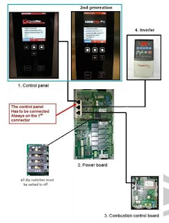
How to configure the type of oven
The setup process of the oven must be done after replacing one of the following
components: CPU board, power board, inverter, combustion control board. It is required to
make all the boards communication with one another and to select the correct operating
parameters of the oven.
Operate as follow:
— Enter the service menu
— Select the «oven type»
— Select the type of oven
— Wait until the end of the procedure and check the list of devices in comparison with
the table below.
— If you get the alarm E20 during the procedure, reset with the reset button and
repeat the procedure by pressing the function «repeat configuration”. If the problem
persists, verify the items found and control the wiring of the components not
detected.
— If at the end of the procedure, the screen does not match the table below, check the
wiring and repeat the configuration by pressing «repeat configuration”.
— If the configuration is correct (the screen corresponds to the table) press «OK».
Alarm log: Selecting this voice you get the list of the last thirty alarms that have occurred
on the oven. The list will show you the alarm code, date and time.
Temperature: Allows you to configure the temperature unit used in the normal operation
of the oven. The choices can be °C or °F. To change the setting, put the cursor on the line
«Temperature» and select the new unit pushing the knob.
Water Hardness: Allows you to set the parameter of hardness of water. This determines
the quantity of chemicals and water used during washing,
Update SW, FW: This selection start the process of updating the software on the CPU
(1a) and the firmware on the power board.
Before performing the upgrade the USB stick (recommended max. size 4GB) should be
inserted into the connector (the stick must be formatted FAT or FAT32 and contain a
directory «AngeloPo» with all the necessary files inside)
How to update software and firmware
To update the software and firmware, proceed as follows:
— Enter the service menu
— Insert the key into the USB connector
— Select «Update SW, FW»
— Wait until the end of the procedure and follow the instructions that appear on the
display
— During this procedure the message “turn off and on the oven” will appear. This has
to be done by the green power switch. Attention! Don’t remove the USB Stick! (if
you switch from version 1.x to 2.x, the system will require a second reboot, again
without removing the USB stick!)
— Remove the USB stick only when the complete update has been finished (when the
main menu is displayed)
WARNING
In case of power loss during this procedure, both the electronic boarding could be
damaged beyond repair
Email : infothehan6@gmail.com 💻 Error Code’s Messages
Inverter Alarm Table NEXT PAGE👇LATEST MODEL
E06:3 The inverter bus voltage is lower than
85% of the nominal value check the inverter voltage (220VAC)
E06:4 the inverter bus voltage has dropped
below the minimum allowable check the inverter voltage (220VAC)
E06:5 the inverter bus voltage has raised up
to the maximum allowable check the inverter voltage (220VAC)
E06:6
The inverter is not able to turn the
motor
check that the motor is free to move. Check that
the three phases are connected to the motor.
E06:7 Motor overload
check that the motor is free to move and doesn’t
touch any other item
E06:8 Excessive heating of the dissipater
verify that the ambient temperature is below
50°C. Verify that the cooling fan inside the
inverter works properly
E06:12 The output current too high
check that the motor is free to move and doesn’t
touch any other item
E06:13
Found scattered current too high
between one of the phases and earth.
check that one or more phases of the motor
power supply are not short circuited with the
mass
E06:33 Automatic restart failed
There was an alarm 4, 5, 6, 7, 8, 12 or 63, but
the automatic restart was unsuccessful. Remove
the cause of these alarms and restart.
E06:38 Phase U short circuited with GND
check the correct connection of the motor and
check that the phase U of motor supply is not
short circuited to the GND
E06:39 Phase V short circuited with GND
check the correct connection of the motor and
check that the phase V of motor supply is not
short circuited to the GND
E06:40 Phase W short circuited with GND
check the correct connection of the motor and
check that the phase W of motor supply is not
short circuited to the GND
E06:41 between phases a UV excess current
flows
check the correct connection of the motor and
that the phases U and V of the motor power
supply are not short circuited together
E06:42 between phases a UW excess current
flows
check the correct connection of the motor and
that the phases U and W of the motor power
supply are not short circuited together
E06:43 between phases a VW excess current
flows
check the correct connection of the motor and
that the phases V and W of the motor power
supply are not short circuited together
E06:64 High current limit exceeded 150% for 1
minute or 200% for 3 seconds
check that the motor is free to move and doesn’t
touch and other item
E06:70 inverter power section faulty Check the inverter voltage (220VAC)
E06:71 Excessive communication errors
check that the cable connecting the serial line is
properly connected.
E06:81 Communication breakdown
check that the cable connecting the serial line is
properly connected.
E06:100 Inverter checksum error Replace the inverter
E06:122 Inverter control section faulty Replace the inverter
E06:255 Inverter blocked
check the connection between terminal 1 and
terminal 11 on the inverter.
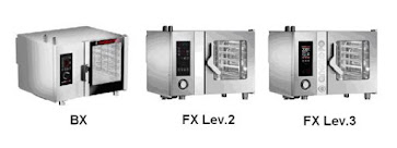
Below the list of the configurable ovens, in bold the models equipped with the inverter
Oven Model Inverter Combustion Control
FX61E1 0 0 FX61E2 0 0 FX82E1 0 0 FX82E2 0 0 FX101E1 0 0 FX101E2 0 0 FX122E1 0 0 FX122E2 0 0 FX201E2 0 0 FX202E2 0 0
FX61G1 0 1 FX61G2 0 1 FX82G1 0 1 FX82G2 0 1
FX101G1 0 1 FX101G2 0 1
FX122G1 0 1
FX122G2 0 1
FX201G2 0 2 FX202G2 0 2 FX61E2S 1 0
FX82E2S 1 0 FX101E2S 1 0
FX122E2S 1 0
FX201E2S 2 0
FX202E2S 2 0
FX61G2S 1 1
FX82G2S 1 1
FX101G2S 1 1 FX122G2S 1 1 FX201G2S 2 2 FX202G2S 2 2
Alarm on
display
Problem (on
the manual)
Solution (on the
manual)
Note (on the
manual)
Note for Service
OPE
Oven door
opening or
closure request.
Open or close the oven
door. Inform the aftersales service if this
message continues to be
displayed.
The cooking
cycle does not
start until the
door has been
opened or
closed as
required.
Check the door magnetic micro switch,
to be correctly connected to the power
PCB by wires 42 and 43. It could be
interruption or short circuit.
CLE
W01
W02
Cleaning alarm — —
See chapter 5.6
(cleaning warnings)
E01:CC
The cooking
chamber probe
has failed or is
not properly
connected.
(Short circuit)
Inform the after-sales
service.
The oven’s
functions are
disabled so no
cooking
cycles can be
carried out.
Check the chamber probe. The
resistance value must be about 1100
Ohm at 25°C. The probe is connected
to the terminals 44 and 45 of the power
PCB.
E01:—
The cooking
chamber probe
has failed or is
not properly
connected.
(Circuit open)
Inform the after-sales
service.
The oven’s
functions are
disabled so no
cooking
cycles can be
carried out.
Check the chamber probe. The
resistance value must be about 1100
Ohm at 25°C. The probe is connected
to the terminals 44 and 45 of the power
PCB.
E02:CC
The product
core probe has
failed.
(Short circuit)
Check the position of the
product core probe or
inform the after-sales
service if it is faulty.
Cooking
cycles with
product core
probe cannot
be carried out.
Check the core probe. The resistance
value must be about 1100 Ohm at
25°C. On the ovens level 2, the probe
is connected to the terminals 46 and 47
of the power PCB. On the ovens level
3, the multipoint core wires are
connected to terminals 74-75-76-77-78
(wires red-yellow-blue-green-black) of
the expansion PCB, and the white one
Alarm on
display
Problem (on
the manual)
Solution (on the
manual)
Note (on the
manual)
Note for Service
E02:—
The product
core probe has
failed.
(Circuit open)
Check the position of the
product core probe or
inform the after-sales
service if it is faulty.
Cooking
cycles with
product core
probe cannot
be carried out.
Same as above
E03:CC
The steam
discharge probe
has failed.
(Short circuit)
Inform the after-sales
service.
Convection
and steam
cooking
cycles can still
be carried out.
Check the drain probe. The resistance
value must be about 1100 Ohm at
25°C. The probe is connected to the
terminals 48 and 49 of the power PCB.
E03:—
The steam
discharge probe
has failed.
(Circuit open)
Inform the after-sales
service.
Convection
and steam
cooking
cycles can still
be carried out.
Same as above.
E04
The motoroperated valve
is not positioned
correctly.
Switch on the oven again
and if the problem
persists inform the aftersales service.
Convection
and steam
cooking
cycles can still
be carried out.
Check that the motor-operated valve is
not blocked. The motor is connected to
pole 11. The micro-switch terminals C
and NC are connected to the terminals
37 and 38 of the power PCB. Verify the
3,15 A fuse (delayed) on the relays
PCB.
E05
Safety
thermostat
failure.
Inform the after-sales
service.
The oven’s
functions are
disabled so no
cooking
cycles can be
carried out.
Reset the safety thermostat. Check
that the thermostat capillary is not bent,
squeezed or broken. Test the oven at
the maximum temperature for some
minutes.
E06
Motor overload
tripped.
Inform the after-sales
service.
The oven’s
functions are
disabled so no
cooking
cycles can be
carried out.
Reset the motor overload protection
relay (L1 and L2) or reset the alarm
from the keyboard (L3). For L3 only,
check the inverter alarm list. Check the
motor to rotate free and the 3 phases
in case of 3 phases power supply.
Alarm on
display
Problem (on
the manual)
Solution (on the
manual)
Note (on the
manual)
Note for Service
E07
Power board
alarm
Inform the after-sales
service.
The oven’s
functions are
disabled so no
cooking
cycles can be
carried out.
Control the dip switch settings of the
power board. The switches 1, 2, 3, and
4 of the DP1 must be set to OFF.
E08
The vacuum
probe has failed.
Press reset button.
Check if the vacuum
probe is correctly
connected to the plug on
the control board.
Connect and
disconnect the
vacuum probe
only when the
oven is not
working. If the
problem
persists, call
the after-sales
service.
Check the vacuum probe. The
resistance value must be about 1100
Ohm at 25°C. The probe is connected
to the terminals 50 and 51 of the panel
PCB. Verify the connector terminals
are clean and be sure to follow the
user instructions.
E09
Exceeded
maximum
temperature
allowed in room
(Probe is set to
315°)
Inform the after-sales
service.
The oven’s
functions are
enabled so
cooking
cycles can be
carried out.
Check the chamber probe, and check
the contactors are non blocked
E10
Electrical
component
compartment
has overheated.
The oven solves the
problem on its own.
The oven’s
functions are
enabled so
cooking
cycles can be
carried out.
The chamber heating will be
temporarily disabled. Check the panel
board cooling fan. Remove and clean
the air gratings located on the front of
the oven. This alarm will be
automatically reset when the
temperature drops down.
E11
Electronic circuit
board
diagnostics
tripped.
Inform the after-sales
service.
The oven’s
functions are
disabled so no
cooking
cycles can be
carried out.
This alarm will appear in the case the
alarm
E10 has not been removed and
the temperature on PCB has rised up
to 69°C. Follow the above instructions.
Alarm on
display
Problem (on
the manual)
Solution (on the
manual)
Note (on the
manual)
Note for Service
E13
Electronic circuit
board
diagnostics
tripped.
Inform the after-sales
service.
The oven’s
functions are
disabled so no
cooking
cycles can be
carried out.
Communication failure between the
boards or peripheral devices. Verify
electrical connections.
E13 = Power Board — CPU
E13a= Inverter 1
E13b= Combustion control board 1
E13c= Inverter 2
E13d= Combustion control board 2
E14
Electronic circuit
board
diagnostics
tripped.
Inform the after-sales
service.
The oven’s
functions are
disabled so no
cooking
cycles can be
carried out.
PCB temperature probe failure.
Replace the power board or the CPU
board.
E14V = CPU
E14Q = power board
E19 The humidity
probe has failed.
Inform the after-sales
service.
The oven’s
functions are
enabled so
cooking
cycles can be
carried out.
Check the connector terminals on the
probe and on the power board.
E20 Configuration
error
Inform the after-sales
service.
The oven’s
functions are
disabled so no
cooking
cycles can be
carried out.
Found inconsistencies between the
type of oven and installed boards.
Verify the installed boards (display,
power board) and devices (inverter and
combustion control), verify their proper
connection on net cables and repeat
the configuration of the oven.
E21 – E26 Washing cycle
alarms See chapter 5.4
E27 Gas test missed See chapter 4.8 (alarm gas chart)
Alarm on
display
Problem (on
the manual)
Solution (on the
manual)
Note (on the
manual)
Note for Service
E28
Valve not
working
Press reset button
The oven’s
functions are
enabled so
cooking
cycles can be
carried out.
Washing
programs are
disabled.
Check the connector terminals on the
valve and on the power board.
E29 Core probe not
inserted
Press reset button
The oven’s
functions are
enabled so
cooking
cycles can be
carried out.
—
E30 – E38
Electronic circuit
board
diagnostics
tripped.
Press reset button
If the problem
persists
inform the
after-sales
service.
Protections against electromagnetic
interferences. Check all the ground
wiring of the equipment. In case of gas
version, please check ignition electrode
and cover protections to be properly
fitted. Check all the wirings relative to
the ignition system. Check the correct
insulation of the cable.
E80 – E85


TROUBLESHOOTING
The appliance has been tested before being put into service.
The information provided below is intended to assist in the identification and correction
of any anomalies and malfunctions which might occur during use.
The user can solve some of these problems himself, but for others specific technical
knowledge or skill is required, and so they must only be carried out by qualified staff
with recognised experience acquired in the specific sector of operation.
The appliance does not
switch on
Cooking cycle does not start
or stops suddenly
IT
TABLE OF ALARM INDICATIONS
GB
If the problem or fault noticed is not amongst those
listed in the table, consult the «Key to Alarms» table
DE
provided below.
The information provided below s intended to identify
FR
the alarm signals which appear on the display (7).
ES
Important
Press button (12) to reset the alarm and the cook-
ing cycle restarts automatically; if this is not the
case, press the start key (16).
English
FAULT
Cause
Fuse «blown»
Electronic circuit board damaged
Control board electronic circuit board
damaged
Alarm triggered
Safety or protection device (safety
thermostat or overload cutout)
tripped
Fault
Cause
— 20 —
Remedy
Replace the fuse (see page 30)
Contact the after-sales service
Contact the after-sales service
Consult the «Key to Alarms» table
Consult the «Key to Alarms» table +
Press device reset button
7
12
16
Use and installation manual
6
IDM-39619500100.tif
Angelopo Service Code,Wiring Diagram,Troubleshooting,How to diagnose Machine,Software UpDate’s — Angelo po combistar — Angelo po Spares Parts — Error Codes
small kitchen design, cook ware kitchen units, pantry organization, marble countertops ,kitchen cabinet near to me, modular kitchen designs, island kitchen worktops, kitchen items spoon, rest kitchen timer,
open kitchen design, ikea cabinet,s ikea kids kitchen, kitchen makeovers, used kitchen ,cabinets kitchen layouts, ikea countertop,kitchen cabinets cheap, kitchen room design , kitchen island design, best kitchen designs, second hand kitchens, kitchen floor, ikea toy kitchen, custom kitchen cabinets ,cabinet designs , ikea pantry cabinet
NEXT PAGE
Note : Subscribe or- E-Mail and YouTube below to get more information,we are ready to help you our best don’t hesitate to contact us.
How to configure the type of oven
The setup process of the oven must be done after replacing one of the following
components: CPU board, power board, inverter, combustion control board. It is required to
make all the boards communication with one another and to select the correct operating
parameters of the oven.
Operate as follow:
— Enter the service menu
— Select the «oven type»
— Select the type of oven
— Wait until the end of the procedure and check the list of devices in comparison with
the table below.
— If you get the alarm E20 during the procedure, reset with the reset button and
repeat the procedure by pressing the function «repeat configuration”. If the problem
persists, verify the items found and control the wiring of the components not
detected.
— If at the end of the procedure, the screen does not match the table below, check the
wiring and repeat the configuration by pressing «repeat configuration”.
— If the configuration is correct (the screen corresponds to the table) press «OK».
Alarm log: Selecting this voice you get the list of the last thirty alarms that have occurred
on the oven. The list will show you the alarm code, date and time.
Temperature: Allows you to configure the temperature unit used in the normal operation
of the oven. The choices can be °C or °F. To change the setting, put the cursor on the line
«Temperature» and select the new unit pushing the knob.
Water Hardness: Allows you to set the parameter of hardness of water. This determines
the quantity of chemicals and water used during washing,
Update SW, FW: This selection start the process of updating the software on the CPU
(1a) and the firmware on the power board.
Before performing the upgrade the USB stick (recommended max. size 4GB) should be
inserted into the connector (the stick must be formatted FAT or FAT32 and contain a
directory «AngeloPo» with all the necessary files inside)
How to update software and firmware
To update the software and firmware, proceed as follows:
— Enter the service menu
— Insert the key into the USB connector
— Select «Update SW, FW»
— Wait until the end of the procedure and follow the instructions that appear on the
display
— During this procedure the message “turn off and on the oven” will appear. This has
to be done by the green power switch. Attention! Don’t remove the USB Stick! (if
you switch from version 1.x to 2.x, the system will require a second reboot, again
without removing the USB stick!)
— Remove the USB stick only when the complete update has been finished (when the
main menu is displayed)
WARNING
In case of power loss during this procedure, both the electronic boarding could be
damaged beyond repair
Email : infothehan6@gmail.com 💻 Error Code’s Messages
Inverter Alarm Table NEXT PAGE👇LATEST MODEL
E06:3 The inverter bus voltage is lower than
85% of the nominal value check the inverter voltage (220VAC)
E06:4 the inverter bus voltage has dropped
below the minimum allowable check the inverter voltage (220VAC)
E06:5 the inverter bus voltage has raised up
to the maximum allowable check the inverter voltage (220VAC)
E06:6
The inverter is not able to turn the
motor
check that the motor is free to move. Check that
the three phases are connected to the motor.
E06:7 Motor overload
check that the motor is free to move and doesn’t
touch any other item
E06:8 Excessive heating of the dissipater
verify that the ambient temperature is below
50°C. Verify that the cooling fan inside the
inverter works properly
E06:12 The output current too high
check that the motor is free to move and doesn’t
touch any other item
E06:13
Found scattered current too high
between one of the phases and earth.
check that one or more phases of the motor
power supply are not short circuited with the
mass
E06:33 Automatic restart failed
There was an alarm 4, 5, 6, 7, 8, 12 or 63, but
the automatic restart was unsuccessful. Remove
the cause of these alarms and restart.
E06:38 Phase U short circuited with GND
check the correct connection of the motor and
check that the phase U of motor supply is not
short circuited to the GND
E06:39 Phase V short circuited with GND
check the correct connection of the motor and
check that the phase V of motor supply is not
short circuited to the GND
E06:40 Phase W short circuited with GND
check the correct connection of the motor and
check that the phase W of motor supply is not
short circuited to the GND
E06:41 between phases a UV excess current
flows
check the correct connection of the motor and
that the phases U and V of the motor power
supply are not short circuited together
E06:42 between phases a UW excess current
flows
check the correct connection of the motor and
that the phases U and W of the motor power
supply are not short circuited together
E06:43 between phases a VW excess current
flows
check the correct connection of the motor and
that the phases V and W of the motor power
supply are not short circuited together
E06:64 High current limit exceeded 150% for 1
minute or 200% for 3 seconds
check that the motor is free to move and doesn’t
touch and other item
E06:70 inverter power section faulty Check the inverter voltage (220VAC)
E06:71 Excessive communication errors
check that the cable connecting the serial line is
properly connected.
E06:81 Communication breakdown
check that the cable connecting the serial line is
properly connected.
E06:100 Inverter checksum error Replace the inverter
E06:122 Inverter control section faulty Replace the inverter
E06:255 Inverter blocked
check the connection between terminal 1 and
terminal 11 on the inverter.
Below the list of the configurable ovens, in bold the models equipped with the inverter
Oven Model Inverter Combustion Control
FX61E1 0 0 FX61E2 0 0 FX82E1 0 0 FX82E2 0 0 FX101E1 0 0 FX101E2 0 0 FX122E1 0 0 FX122E2 0 0 FX201E2 0 0 FX202E2 0 0
FX61G1 0 1 FX61G2 0 1 FX82G1 0 1 FX82G2 0 1
FX101G1 0 1 FX101G2 0 1
FX122G1 0 1
FX122G2 0 1
FX201G2 0 2 FX202G2 0 2 FX61E2S 1 0
FX82E2S 1 0 FX101E2S 1 0
FX122E2S 1 0
FX201E2S 2 0
FX202E2S 2 0
FX61G2S 1 1
FX82G2S 1 1
FX101G2S 1 1 FX122G2S 1 1 FX201G2S 2 2 FX202G2S 2 2
Alarm on
display
Problem (on
the manual)
Solution (on the
manual)
Note (on the
manual)
Note for Service
OPE
Oven door
opening or
closure request.
Open or close the oven
door. Inform the aftersales service if this
message continues to be
displayed.
The cooking
cycle does not
start until the
door has been
opened or
closed as
required.
Check the door magnetic micro switch,
to be correctly connected to the power
PCB by wires 42 and 43. It could be
interruption or short circuit.
CLE
W01
W02
Cleaning alarm — —
See chapter 5.6
(cleaning warnings)
E01:CC
The cooking
chamber probe
has failed or is
not properly
connected.
(Short circuit)
Inform the after-sales
service.
The oven’s
functions are
disabled so no
cooking
cycles can be
carried out.
Check the chamber probe. The
resistance value must be about 1100
Ohm at 25°C. The probe is connected
to the terminals 44 and 45 of the power
PCB.
E01:—
The cooking
chamber probe
has failed or is
not properly
connected.
(Circuit open)
Inform the after-sales
service.
The oven’s
functions are
disabled so no
cooking
cycles can be
carried out.
Check the chamber probe. The
resistance value must be about 1100
Ohm at 25°C. The probe is connected
to the terminals 44 and 45 of the power
PCB.
E02:CC
The product
core probe has
failed.
(Short circuit)
Check the position of the
product core probe or
inform the after-sales
service if it is faulty.
Cooking
cycles with
product core
probe cannot
be carried out.
Check the core probe. The resistance
value must be about 1100 Ohm at
25°C. On the ovens level 2, the probe
is connected to the terminals 46 and 47
of the power PCB. On the ovens level
3, the multipoint core wires are
connected to terminals 74-75-76-77-78
(wires red-yellow-blue-green-black) of
the expansion PCB, and the white one
Alarm on
display
Problem (on
the manual)
Solution (on the
manual)
Note (on the
manual)
Note for Service
E02:—
The product
core probe has
failed.
(Circuit open)
Check the position of the
product core probe or
inform the after-sales
service if it is faulty.
Cooking
cycles with
product core
probe cannot
be carried out.
Same as above
E03:CC
The steam
discharge probe
has failed.
(Short circuit)
Inform the after-sales
service.
Convection
and steam
cooking
cycles can still
be carried out.
Check the drain probe. The resistance
value must be about 1100 Ohm at
25°C. The probe is connected to the
terminals 48 and 49 of the power PCB.
E03:—
The steam
discharge probe
has failed.
(Circuit open)
Inform the after-sales
service.
Convection
and steam
cooking
cycles can still
be carried out.
Same as above.
E04
The motoroperated valve
is not positioned
correctly.
Switch on the oven again
and if the problem
persists inform the aftersales service.
Convection
and steam
cooking
cycles can still
be carried out.
Check that the motor-operated valve is
not blocked. The motor is connected to
pole 11. The micro-switch terminals C
and NC are connected to the terminals
37 and 38 of the power PCB. Verify the
3,15 A fuse (delayed) on the relays
PCB.
E05
Safety
thermostat
failure.
Inform the after-sales
service.
The oven’s
functions are
disabled so no
cooking
cycles can be
carried out.
Reset the safety thermostat. Check
that the thermostat capillary is not bent,
squeezed or broken. Test the oven at
the maximum temperature for some
minutes.
E06
Motor overload
tripped.
Inform the after-sales
service.
The oven’s
functions are
disabled so no
cooking
cycles can be
carried out.
Reset the motor overload protection
relay (L1 and L2) or reset the alarm
from the keyboard (L3). For L3 only,
check the inverter alarm list. Check the
motor to rotate free and the 3 phases
in case of 3 phases power supply.
Alarm on
display
Problem (on
the manual)
Solution (on the
manual)
Note (on the
manual)
Note for Service
E07
Power board
alarm
Inform the after-sales
service.
The oven’s
functions are
disabled so no
cooking
cycles can be
carried out.
Control the dip switch settings of the
power board. The switches 1, 2, 3, and
4 of the DP1 must be set to OFF.
E08
The vacuum
probe has failed.
Press reset button.
Check if the vacuum
probe is correctly
connected to the plug on
the control board.
Connect and
disconnect the
vacuum probe
only when the
oven is not
working. If the
problem
persists, call
the after-sales
service.
Check the vacuum probe. The
resistance value must be about 1100
Ohm at 25°C. The probe is connected
to the terminals 50 and 51 of the panel
PCB. Verify the connector terminals
are clean and be sure to follow the
user instructions.
E09
Exceeded
maximum
temperature
allowed in room
(Probe is set to
315°)
Inform the after-sales
service.
The oven’s
functions are
enabled so
cooking
cycles can be
carried out.
Check the chamber probe, and check
the contactors are non blocked
E10
Electrical
component
compartment
has overheated.
The oven solves the
problem on its own.
The oven’s
functions are
enabled so
cooking
cycles can be
carried out.
The chamber heating will be
temporarily disabled. Check the panel
board cooling fan. Remove and clean
the air gratings located on the front of
the oven. This alarm will be
automatically reset when the
temperature drops down.
E11
Electronic circuit
board
diagnostics
tripped.
Inform the after-sales
service.
The oven’s
functions are
disabled so no
cooking
cycles can be
carried out.
This alarm will appear in the case the
alarm
E10 has not been removed and
the temperature on PCB has rised up
to 69°C. Follow the above instructions.
Alarm on
display
Problem (on
the manual)
Solution (on the
manual)
Note (on the
manual)
Note for Service
E13
Electronic circuit
board
diagnostics
tripped.
Inform the after-sales
service.
The oven’s
functions are
disabled so no
cooking
cycles can be
carried out.
Communication failure between the
boards or peripheral devices. Verify
electrical connections.
E13 = Power Board — CPU
E13a= Inverter 1
E13b= Combustion control board 1
E13c= Inverter 2
E13d= Combustion control board 2
E14
Electronic circuit
board
diagnostics
tripped.
Inform the after-sales
service.
The oven’s
functions are
disabled so no
cooking
cycles can be
carried out.
PCB temperature probe failure.
Replace the power board or the CPU
board.
E14V = CPU
E14Q = power board
E19 The humidity
probe has failed.
Inform the after-sales
service.
The oven’s
functions are
enabled so
cooking
cycles can be
carried out.
Check the connector terminals on the
probe and on the power board.
E20 Configuration
error
Inform the after-sales
service.
The oven’s
functions are
disabled so no
cooking
cycles can be
carried out.
Found inconsistencies between the
type of oven and installed boards.
Verify the installed boards (display,
power board) and devices (inverter and
combustion control), verify their proper
connection on net cables and repeat
the configuration of the oven.
E21 – E26 Washing cycle
alarms See chapter 5.4
E27 Gas test missed See chapter 4.8 (alarm gas chart)
Alarm on
display
Problem (on
the manual)
Solution (on the
manual)
Note (on the
manual)
Note for Service
E28
Valve not
working
Press reset button
The oven’s
functions are
enabled so
cooking
cycles can be
carried out.
Washing
programs are
disabled.
Check the connector terminals on the
valve and on the power board.
E29 Core probe not
inserted
Press reset button
The oven’s
functions are
enabled so
cooking
cycles can be
carried out.
—
E30 – E38
Electronic circuit
board
diagnostics
tripped.
Press reset button
If the problem
persists
inform the
after-sales
service.
Protections against electromagnetic
interferences. Check all the ground
wiring of the equipment. In case of gas
version, please check ignition electrode
and cover protections to be properly
fitted. Check all the wirings relative to
the ignition system. Check the correct
insulation of the cable.
E80 – E85
Пароконвектомат – незаменимая техника на профессиональных кухнях. Поломка такого аппарата является крайне нежелательным явлением для общепита, так как может привести к невозможности подачи заказанного блюда и потере клиентов. В большинстве своем ошибки пароконвектоматов зависят от некорректной эксплуатации оборудования.
Основные правила эксплуатации
- Первый запуск печи проводится с пустой камерой на протяжении получаса и при температуре +200 градусов.
- В начале рабочего дня при загрузке устройства замороженными продуктами или максимально заполнении камеры полуфабрикатами, необходимо провести предварительный нагрев камеры в течение четверти часа при температуре, которая выше стандартного режима на 40 градусов.
- При выкладке сохраняет расстояние между полуфабрикатами не менее 2-х см.
- Открывать камеру во время процесса приготовления рекомендуется как можно реже, чтобы сохранить стабильность температуры.
Важно! Своевременное сервисное обслуживание и ремонт неполадок исключат выход техники из строя и предупредят увеличение расхода электроэнергии.
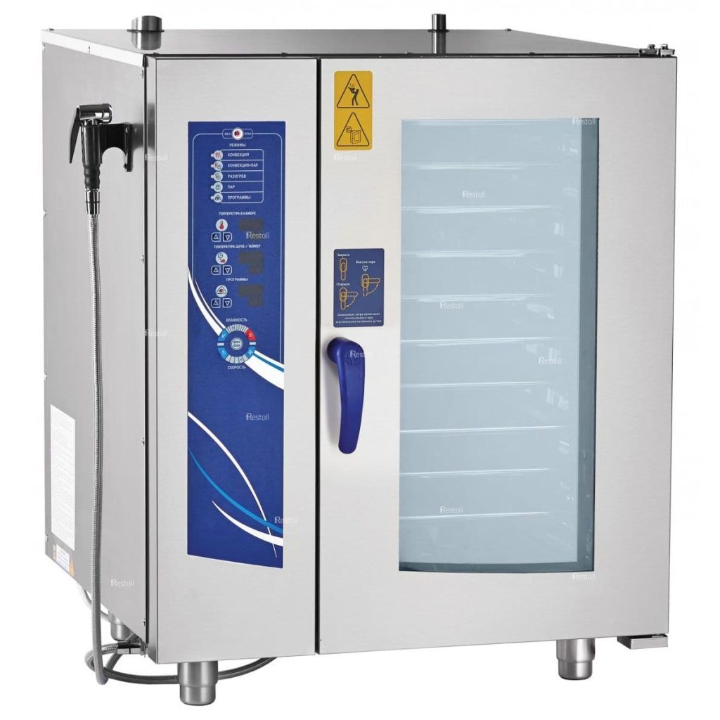
Пароконвектомат Abat: ошибки
Наиболее частными погрешностями работы ПКА Чувашторгтехника являются:
- Е02 (появляется после нажатия кнопки включения и сопровождается звуковой сигнализацией) – повышение предельной температуры (от +75 градусов) в зоне контроллера либо неисправность последнего.
- Е11 (при выставлении программы «Пар») – закрыт кран, подающий воду на пароконвектомат, либо открыт кран слива воды из бойлера, либо недостаточный уровень воды в устройстве (не покрывает электрод).
- Е04 (при попытке запуска устройства) – обрыв термопары.
Подробно все возможные погрешности в работе агрегата и неисправности описаны в руководстве по эксплуатации.
Ошибки пароконвектомата Unox и Rational
Чаще всего при работе с устройством Унокс встречаются следующие поломки:
- ЕЕ1 – неисправность проводки, соединяющих датчик камеры с источником питания.
- AF01 – перегревание мотора при выполнении функции «конвекция».
- AF02 – запуск аварийной термо-защиты.
- EF4 – перегрев двигателя вентилятора.
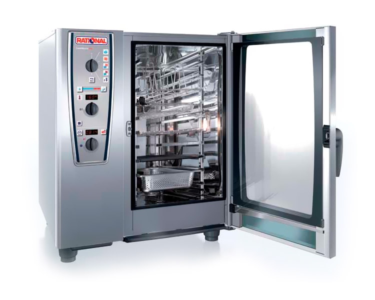
Наиболее частые нарушения функциональности устройства Rational серии SCC:
- OPEn – отсутствует подача воды.
- E7 – неисправность термопары платы управления.
- E8 – поломка регулятора температур.
- CHnG bAtt – потребность замены батарейки в блоке управления, пр.
Не представляет сложности расшифровать коды ошибок пароконвектоматов, но не всегда удается самостоятельно исправить поломку даже при наличии соответствующей инструкции. Компания Кобор предлагает не только купить теплотехнику от лучших производителей, но также и услуги по ее обслуживанию и ремонту для жителей Москвы и области. Посмотреть товары и цены можно в каталоге нашего интернет-магазина. Обеспечивается доставка по всей России.
Коды ошибок пароконвектоматов
Коды ошибок пароконвектомата Rational
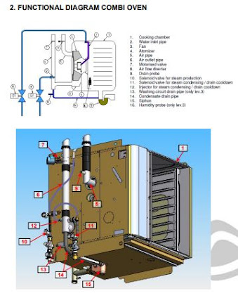
Функциональная Схема
B1 Термопара рабочей камеры
B2 Tермопара коллектора охлаждения
B3 Tермопара датчика температуры сердцевины
B5 Tермопара парогенератора
F3 Aварийный термостат парогенератора , температура срабатывания 160°C
F4 Aварийный термостат рабочей камеры, температура срабатывания 360°C
Y1 Mагнитный клапан подачи воды в парогенератор
Y2 Магнитный клапан подачи воды в коллектор охлаждения
Y5 Магнитный клапан clima
M1 Нижний мотор вентилятора (без перемычки)
M4 Насос парогенератора
P1 Датчик дифференциального давления
S2 Электрод уровня воды в парогенераторе
S3 Датчик контакта двери
Только для CM_P 201/202:
M2 Нижний мотор вентилятора (с перемычкой)
Коды ошибок
При возникновении ошибки в работе аппарата, код ошибки высвечивается на дисплее, а
затем сохраняется в истории
H2O — Открыть воду Недостаток воды / открыть кран подачи воды
CHnG — Поменять полярность Поменять полярность «фаза – ноль» (только для газовых аппаратов)
rES — Обрыв пламени Пламя не распознается после зажигания
Att — Осторожно — горячо Температура платы управления превысила 70°C или 75°C (для электрических
201/202) ТЭНы выключены до тех пор, пока температура не опуститься ниже указанных значений.
Е10 — Насос M4 парогенератора Насос неисправен
Е16 — Внешнее ПЗУ Структура данных платы управления более старая, чем во внешнем ПЗУ
Е17 — Внешнее ПЗУ Не распознается
Е18 — Внешнее ПЗУ Внешнее ПЗУ неисправно
Е19 — Внешнее ПЗУ Внешнее ПЗУ не подключено
Е20 — Неисправна термопара
1=термопара рабочей камеры
2=термопара коллектора
4= термопара влажности
8= термопара парогенератор
Е23 — Температура B5 повышается без запроса на нагрев, твердотельные реле по контуру «ПАР» неисправны
Постоянный звуковой сигнал зуммера
Е24 — Температура B1 повысилась более чем на 100°C без запроса на нагрев, твердотельные реле по контуру «СУХОЙ ЖАР» неисправны Постоянный звуковой сигнал зуммера
Е28 — Термопара В5 1 – температура B5 ниже -5°C 2 – температура B5 выше 150°C, ТЭНы парогенератора выключены, индикация в течении 30 сек
Е29 — Температура платы управления Температура платы превысила 80°C
Е30 — Аварийный контроль влажности Аварийный контроль влажности активен более 15 минут
Е31 — Термокерн Неисправен
Е32 — Блок зажигания Ошибка зажигания Неисправен блок зажигания 0 = верхний 1 = нижний 2 = оба
Е33 — Блок зажигания Пламя не распознается Неисправен блок зажигания 0 = верхний 1 = нижний 2 = оба
Е34 — Ошибка шины данных 1 = верхний мотор 2 = нижний мотор 4 = верхний блок зажигания 8 = нижний блок зажигания
Е 35 — Зонт UltraVent Шина данных зонта не распознается, неисправна или нет подачи напряжения на зонт
Е36 — Датчик Р1 Датчик неисправен
Е37 — Датчик Р1 Сигнал датчика вышел за пределы допуска
Е38 — Переключатель режимов Неисправен
Е39 — Потенциометр температуры Неисправен
Е40 — Потенциометр таймера / термокерна Неисправен
Е50 — Таймер реального времени не распознается Неисправен
Е51 — Напряжение батарейки ниже 1,5 В заменить батарейку, тип CR 2032
Е60 — Инициализация блока зажигания неправильная Некорректная информация о скорости нагнетателя
выключить и снова включить аппарат, выполнить восстановление внешнего ПЗУ
Сервис Проверить или заменить
10 Насос парогенератора, контейнер наполнения, шланг насоса
11 Электрод уровня, пропускная способность датчика CDS, плата вхвых.
12 Неисправен датчик CDS
13 Проверить электрод уровня
14 Проверить электрод уровня, измерить электропроводность воды
17 Связаться с RATIONAL, использовать ПО для восстановления
19 Заменить SD-карту
20.x Неисправна термопара, -1 = рабочая камера B1; -2 = коллектор охлаждения B2; -4 = термопара влажности B4; -8 = парогенератор B5; -16: Рабочая камера внизу B9 (напольный аппарат); ; -32: отек для установки B10 (XS)
23 Твердотельные реле по контуру «Пар»
24 Твердотельные реле по контуру «Сухой жар»
25 Нет увеличения нагрузки на мотор при попадании воды на вентилятор: Проверить подачу идавление воды, шланги, датчик CDS, положение навесных рам и рам-тележек с направляющими
26 Только XS: Шаровой клапан не открывается; проверить в функциональном тесте, при необходимости заменить
27 Только XS: Шаровой клапан не закрывается; проверить в функциональном тесте, при необходимости заменить
28.x Термопара: -1: Парогенератор B5 слишком горячий (>170 C); -2: рабочая камера B1 слишком горячая (>350 °C); -4: рабочая камера B1 слишком холодная (<2 °C)
29 Слишком высокая температура платы: проверить воздушный фильтр, вентилятор охлажде-
ния и уплотнение панели управления.
30 Ошибка контроля влажности; проверить датчик дифференциального давления P1
31.x Термопара термокерна В3: -1: Неисправен термокерн рабочей камеры; -2: Аварийный режим термокерна рабочей камеры; -11/12: Термокерн USB 1 неисправен/аварийный режим; -21/22: Термокерн USB 2 неисправен/аварийный режим
32.x Блок зажигания: газовый кран; замените блок зажигания только, если газовые ошибки 33, 36, 39 или 42 возникли более 5-ти раз
33.x Газовая ошибка: проверить газовый кран, газовый клапан или управление от блока зажигания к газовому клапану
34.xx Ошибка сигнала шины: -1 верхний мотор; -2 средний моторе; -4 нижний мотор; -8 плата насоса; -16 подача питания платы вх./вых.; -32 блок зажигания
35 UltraVent: Сигнал шины / внутренняя коммуникация
35.x Ошибка UltraVent: -1 ошибка напряжения; -2 ошибка распознавания фильтра; -3 ошибка контроля термопары; -4 неисправность термопары защиты мотора; -5: Предварительное уведомление (замена фильтра) -6 загрязнение фильтра (немедленная замена); -7 фильтр не установлен/не измеряется дифференциальное давление
36 Ошибка датчика дифференциального давления (нет сигнала 0,5 В; проверить входной сигнал 12 В на P1); P1 должен быть установлен горизонтально
37 Сбой упр. микроклиматом: Проверить подключения шлангов
40 Проверить насос Care (M18) в функциональном тесте (Внимание! одновременно включается Y4 , запустить программу ополаскивания)
41 Функция увлажнения: Проверить клапан Y3, форсунку и трубку впрыска на наличие накипи; CDS не измеряет импульсы; Сбросить ошибку, запустив программу ополаскивания
42.x Не открывается клапан: -1: клапан Y1; -2: Клапан Y2; -3: увлажнение Y3; -4: клапан Care Y4; -5: клапан Klima Y5 / Y15; -6: промывочный клапан Y14
44 Нет нагрева парогенератора или нагрев недостаточен;
46.x SC-насос (M4); -1: неисправен; -2: слишком низкая производительность
47.x Сливной насос M15; -1: неисправен; -2: Слишком низкая производительность
48.x Циркуляционный насос M17; -1: неисправен; -2: Слишком низкая производительность
49.x Насос Care (M18): -1: неисправен; -2: слишком низкая производительность
50 Реальное время (дата и время)
51 Проверить батарейку, при необходимости замените
52 Ошибка светодиодного освещения дверцы: -1 слева; -2 справа
55, 56, 57 Ошибка мотора вентилятора (только в сервисном отчете)
60 Блок зажигания не инициализируется или его работа замедлена — Ошибка в сигнале скорости вращения; выключить и включить аппарат. Изменить тип газа и вернуться к исходному типу газа, при необходимости применить восстановительный файл.
63 Аппарат обнаруживает воду в первый раз после сухой калибровки, после самодиагностики без воды: заново провести калибровку.
70.x -1: Электроотказ вентилятора охлаждения настольного аппарата
-2: Вентилятор охлаждения газового настольного аппарата, электро-/газоотказ напольного аппарата
71.x -1: Сетевая ошибка; -2: Пониженное напряжение блока питания
72 Термостат eSTB для сухого жара или пара: Мигание светодиода на eSTB — ошибка
73.x Ошибка повышенной температуры: -1 верхний мотор; -2 нижний мотор; -4 средний мотор;
-8 плата насоса; -16 блок управления платы вх./вых.; -32 блок зажигания;
75.x 75: Полный отказ интерфейса шины (I2C); -1: Отказ оптимизации энергопотребления; -2: Отказ платы 4-вентильного реле; -3: Отказ платы очистки (XS);
76.x Только США:
-1: ограничено напряжение; -2: ошибка внутренней проверки; -3: неправильная настройка напряжения; -4: слишком большое число каналов; -5: неправильные каналы; -6: неправильное время; -7: ошибка аппаратного обеспечения
110 Ошибка SC-насоса при наличии в парогенераторе раствора Care
120 Нет сигнала электрода уровня при наличии в парогенераторе раствора Care;
130 Необходима ручная очистка от накипи (объем заполнения соответствует 80 % эталонного значения)
Рационал ремонт _скачать учебное пособие
ВЫЗОВ МАСТЕРА
Коды ошибок пароконвектомата Abat Абат
Е02 — (отображается после нажатия на кнопку включения и сопровождается звуковым сигналом). Указывает на увеличение предельной температуры (от +75°С) в зоне контроллера либо его неисправность.
Е11 — (при выставлении режима «Пар»). Возможные причины: закрыт кран, который подает воду на аппарат или открыт кран слива воды из бойлера, либо объем воды в пароконвектомате недостаточен (то есть не покрывает электрод).
Е04 — (при попытке запустить устройство) – обрыв термопары.
Список системных кодов (ошибок) пароконвектоматов Abat (контролер 38 ПКА3 исп 85)
Еrr ch1 — Обрыв термопары «Камера»
Е02 — Аварийная защита (плюс)130/160ºС парогенератора или духовки (плюс) 320ºС
Err — Неисправность датчика холодных спаев или перегрев контроллера
Е07 — Неисправность частотного преобразователя
Системные кода (ошибки), частично блокирующие работу контроллера 38 ПКА3 исп 85
Err 1 ch2 — Обрыв первого канала «Щуп» (Блокируется работа с параметром «Щуп»)
Err 1 ch3 — Обрыв второго канала «Щуп» (Блокируется работа с параметром «Щуп»)
Err 1 ch4 — Обрыв третьего канала «Щуп» (Блокируется работа с параметром «Щуп»)
Е03 — Не правильное подключение электродов – уровень воды на верхнем электроде появляется раньше, чем на нижнем (Блокируется работа с параметром «Пар», «Мойка»)
Е04 — Отсутствие воды в парогенераторе (Блокируется работа с параметром «Пар», «Мойка»)
Е06 — Обрыв датчика заслонки (Блокируется работа с параметром «Пар», «Мойка»)
Err 1 ch5 — Обрыв термопары «Бойлер» (Блокируется режим «Мойка»)
Список системных кодов (ошибок) пароконвектоматов Abat (контролер 38 ПКА3 исп 86)
Е01 — Обрыв термопары «Камера»
Е02 — Аварийная защита (плюс)130/160ºС парогенератора или духовки (плюс) 320ºС
Е05 — Неисправность датчика холодных спаев или перегрев контроллера
Е07 — Неисправность частотного преобразователя
Системные кода (ошибки), частично блокирующие работу контроллера 38ПКА3 исп 86
Е10 — Обрыв первого канала «Щуп» (Блокируется работа с параметром «Щуп»)
Е11 — Обрыв второго канала «Щуп» (Блокируется работа с параметром «Щуп»)
Е12 — Обрыв третьего канала «Щуп» (Блокируется работа с параметром «Щуп»)
Е13 — Не правильное подключение электродов – уровень воды на верхнем электроде появляется раньше, чем на нижнем (Блокируется работа с параметром «Пар», «Мойка)
Е14 — Отсутствие воды в парогенераторе (Блокируется работа с параметром «Пар», «Мойка)
Е20 — Сообщение о необходимости проведения декальцинации парогенератора (Блокируется работа с параметром «Пар», «Мойка)
Е26 — Обрыв датчика заслонки (Блокируется работа с параметром «Пар», «Мойка)
Е21* — Требуется очистка парогенератора (Блокируется работа с параметром «Пар», «Мойка)
Е22 — Обрыв термопары «Бойлер» (Блокируется режим «Мойка»)
ВЫЗОВ МАСТЕРА
Коды ошибок пароконвектомата Unox Унокс
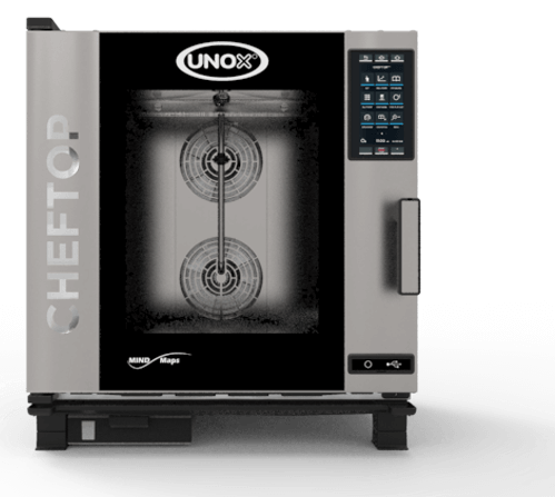
Коды ошибок оборудования Unox предельно просты к расшифроdке. Система самодиагностики дает подсказки до мельчайших подробностей. Вам необходимо записать, либо запомнить код ошибки, для детального его рассмотрения.
AF01 — Ошибка термозащиты мотора.
Возможные причины — Повреждение термозащиты, Разъединение проводов, Повреждена плата мощности, Перегрелся мотор.
AF02 — Ошибка термостата безопасности.
Возможные причины — Перегрев камеры печи выше 320°С, Провод термостата безопасности разъединен, Повреждена плата мощности.
AF03 — Ошибка датчика температуры.
Возможные причины — Оба датчика температуры повреждены или отсоединены, Повреждена плата мощности.
AF04 — Потеря связи между платами мощности и управления.
Возможные причины — Кабель между платами мощности и управления поврежден или плохо соединен, Повреждена плата управления, Повреждена плата мощности, Сильные электромагнитные колебания (магнитное поле).
AF05 — Потеря связи с газовой платой.
Возможные причины — Кабель, соединяющий газовую плату и плату мощности, поврежден или разъединен, Повреждена газовая плата, Поврежден плавкий предохранитель газовой платы, Повреждена плата мощности, NGS параметру платы мощности печи присвоено значение 1, Повреждена плата управления.
AF06 — Ошибка температуры выхлопных газов.
Возможные причины — Температура выхлопных газов выше 620°С, Поврежден датчик температуры выхлопных газов, Повреждена газовая плата.
AF08 — Ошибка датчика тахометра мотора (печь прекращает работу)
1. Необходимо проверить кабель соединяющий плату мощности и датчик тахометра (возможно отсоединен или поврежден).
2. Возможно поврежден сам мотор.
3. Отсутствует пластиковое кольцо-магнит или перепутана полярность при подключении.
4. Сенсор не прилегает к корпусу двигателя.
5. Поврежден сам датчик тахометра.
6. Проверить тормозные сопротивления, а так же пусковые конденсаторы (возможно повреждены).
7. возможно повреждена плата мощности
AF10 — Неверные настройки важнейших значений в EEPROM.
Возможные причины — Повреждена плата мощности, Неверные настройки параметров EEPROM.
WF01 — Ошибка датчика температуры №1
Возможные причины — Датчик №1 не подсоединен или неисправен, Повреждена плата мощности.
WF02 — Ошибка датчика температуры №2
Возможные причины — Датчик №2 не подсоединен или неисправен, Повреждена плата мощности.
WF03 — Ошибка температурного щупа
Возможные причины — Термощуп не подсоединен или неисправен, Повреждена плата мощности.
WF04 — Предупреждение об ошибке тахометра мотора
Возможные причины — Остановка мотора, Датчик тахометра отсоединен или поврежден, Неправильное расположение датчика тахометра, Неправильное расположение магнита в моторе, Повреждена плата мощности.
WF05 — Предупреждение об ошибке вентилятора охлаждения электронных компонентов
Возможные причины — Неправильное соединение охлаждающего вентилятора и платы мощности, Охлаждающий вентилятор поврежден, Повреждена плата мощности.
WF06 — Перегрев платы мощности
Возможные причины — Плата мощности нагрелась до температуры свыше 70°С, Повреждена плата мощности.
WF08 — Газовая плата подсоединена, но печь настроена как электрическая
Возможные причины — Параметр NGS на газовой плате имеет значение
WF09 — Предупреждение об ошибке мотора вентилятора
Возможные причины — Повреждена плата мощности, Поврежден мотор.
WF10 — Предупреждение о неверных настройках параметров EEPROM
Возможные причины — Повреждена плата мощности, Неверные настройки параметров EEPROM.
WF11 — Предупреждение о перегреве газовой платы
Возможные причины — Газовая плата нагрелась до температуры свыше 70°С, Повреждена газовая плата.
WF12 — Предупреждение о перегреве сверхтонкого щупа
Возможные причины — Плата сверхтонкого щупа нагрелась до температуры свыше 70°С, Повреждена плата сверхтонкого щупа.
WF13 — Предупреждение об ошибке сверхтонкого щупа
Возможные причины — Сверхтонкий щуп не подсоединен, Сверхтонкий щуп поврежден, Повреждена плата сверхтонкого щупа.
WF14 — Предупреждение об ошибке многоточечного щупа (вообще не работает)
Возможные причины — Многоточечный щуп подсоединен некорректно, Многоточечный щуп поврежден, Повреждена плата мощности
WF15 — Потеря соединения со сверхтонким щупом
Возможные причины — Кабель, соединяющий плату мощности и сверхтонкий щуп, поврежден или отсоединен, Сверхтонкий щуп поврежден, Повреждена плата мощности.
WF17 — Предупреждение об ошибке многоточечного щупа (частично не работает)
Возможные причины — Многоточечный щуп подсоединен некорректно, Многоточечный щуп поврежден, Повреждена плата мощности.
ВЫЗОВ МАСТЕРА
Коды ошибок пароконвектомата Retigo Ретиго
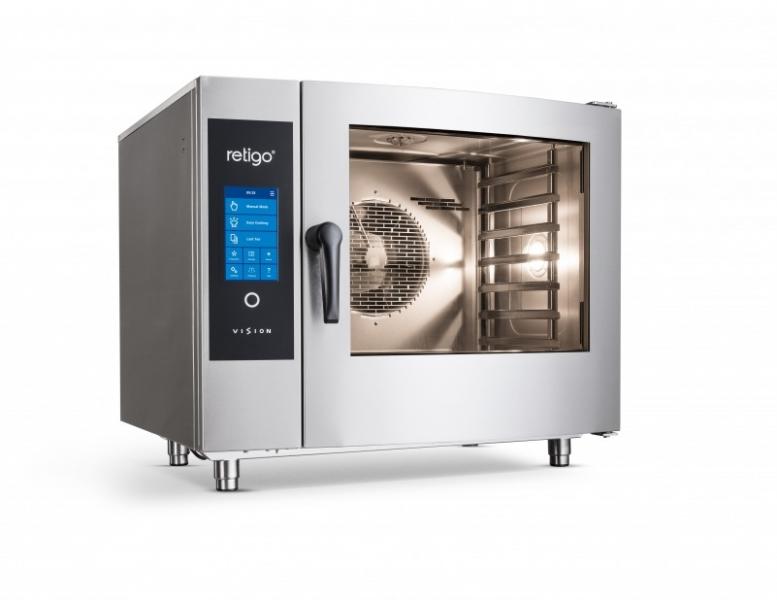
Err 10 Вода достигает максимального уровня, Для удаления сообщения об ошибке нажмите кнопку
но не достигает минимального уровня «ESC». Конвектомат может использоваться только
за две минуты. в режиме «Горячий воздух». Обратитесь в сервисный центр.
Err 11 Для удаления сообщения об ошибке нажмите кнопку Предварительный нагрев бойлера за- «ESC». Конвектомат может использоваться только нимает более 6 минут. в режиме «Горячий воздух». Обратитесь в сервисный центр.
Err 12 При наполнении бойлера макси- Для удаления сообщения об ошибке нажмите кнопку
мальный уровень воды достигается «ESC». Конвектомат может использоваться только в режиме «Горячий воздух». Обратитесь в сервисный центр.
Проверьте линию подачи воды (клапан должен быть
Err 13 При наполнении бойлера минимальный уровень воды не достигается за Для удаления сообщения об ошибке нажмите кнопку 2 минуты. «ESC». Конвектомат может использоваться только в режиме «Горячий воздух». Обратитесь в сервисный центр.
Err 14 Не хватает одной фазы электропитания Обратитесь в сервисный центр.
Err 15 Сбой защиты от тепловой перегрузки двигателя F2. Индикация перегрузки двигателя сверх установленного значения.
Err 16 Предварительный нагрев бойлера занимает более 7 минут. Конвектомат может использоваться только в режиме «Горячий воздух». Обратитесь в сервисный центр.
Err 17 При опорожнении бойлера уровень воды не опускается ниже минимального уровня за 2 минуты. Для удаления сообщения об ошибке нажмите кнопку «ESC». Конвектомат может использоваться только
в режиме «Горячий воздух». Обратитесь в сервисный центр.
Err 18 При опорожнении бойлера уровень воды не опускается ниже максимального уровня за 2 минуты. Проверьте слив. Для удаления сообщения об ошибке нажмите кнопку
«ESC». Конвектомат может использоваться только в режи-
ме «Горячий воздух». Обратитесь в сервисный центр.
Err 19 Бойлер покрыт известью Обратитесь в сервисный центр.
Err 26 Двигатель заслонки не заблокирован Для удаления сообщения об ошибке нажмите кнопку или переключатель находится в замкнутом положении. — «ESC». Конвектомат не может использоваться без
функции «Заслонка».
Err 27 Двигатель заслонки не заблокирован Для удаления сообщения об ошибке нажмите кнопку или переключатель находится в замкнутом положении. — «ESC». Конвектомат не может использоваться без
функции «Заслонка».
Err 28 Сбой переключения положения заслонки. Для удаления сообщения об ошибке нажмите кнопку
«ESC». Конвектомат не может использоваться без функции «Заслонка».
Err 29 Сбой двигателя заслонки. Для удаления сообщения об ошибке нажмите кнопку «ESC». Конвектомат не может использоваться без функции «Заслонка».
Для удаления сообщения об ошибке нажмите кнопку
Err 30 Сбой датчика температуры отходящего пара во всех режимах приготовления продуктов.
Err 31 Сбой датчика температуры слива.
Err 32 Сбой датчика температуры бойлера.
Err 33 Сбой 2 датчика температуры камеры
Err 34 Сбой термощупа – термощуп 1
Err 35 Сбой 1 датчика температуры камеры
Err 36 Сбой термощупа – термощуп 2
Err 40 Плавкий предохранитель камеры (S1, S2) или предохранитель бойлера (S3) Обратитесь в сервисный центр.– защита от перегрева.
Err 60-78 Сбой электронной панели
Err 80-90 Сбой частотного преобразователя .Обратитесь в сервисный центр.
Err 95 Неправильное число оборотов вентилятора
Err 96 Газ не включен Проверьте подачу газа и повторите попытку включить его
Err 97 Недостаточная вытяжка (только для Обратная тяга – выключите вентиляцию под низким давлением
устройств типа B13)
Err 100 Системная ошибка Обратитесь в сервисный центр
ВЫЗОВ МАСТЕРА