
![]()
|
Запуск двигателя и вождение |
93 |
Система удержания на уклоне
Эта система удерживает автомобиль на первой или задней передаче при движе нии на подъем или спуск в течение примерно 3 секунд после отпускания педали тормоза, обеспечивая быстрое и плавное трогание с места.
ABS8 (если установлено)
Помимо выполнения обычных функций ABS, эта система ограничивает возможность переключения на повышающие передачи на поворотах. Блок управления ABS име ет две контрольные лампы:
контрольная лампа ABS желтого цвета;
контрольная лампа EBD красного цвета.
Непрерывное свечение контрольной лампы ABS означает наличие неисправности в системе. Контрольная лампа EBD (электронной системы распределения тормоз ных сил), которая загорается вместе с контрольной лампой 1 (которая, в свою оче редь, означает низкий уровень тормозной жидкости, включение стояночного тор моза или износ тормозных накладок, если включается одна), говорит о том, что си стема EBD не работает.

94 Запуск двигателя и вождение
Круиз-контроль (если установлено)
Система автоматически поддерживает заданную скорость движения автомобиля без необходимости нажимать на педаль акселератора.
ПРЕДУПРЕЖДЕНИЕ: Круиз контроль включается только в том случае, если по сле запуска двигателя педаль сцепления была нажата хотя бы один раз.
Системой круиз контроля не следует пользоваться в условиях оживленного движе ния и на дорогах, где скорость приходится постоянно изменять (например, при дви жении в горной местности).
Круиз контроль можно включать при следующих условиях:
■автомобиль движется на передаче (кроме 1 й);
■скорость автомобиля более 30 км/ч;
■педаль тормоза не нажата;
■педаль сцепления не нажата.
При нажатии педали тормоза или сцепления система круиз контроля выключается.

|
Запуск двигателя и вождение |
95 |
То же происходит, если не достигнута минимальная заданная скорость. Макси мально допустимая скорость хранится в программе электронного блока управле ния и не может быть изменена.
|
Переключатель |
Управление скоростью автомобиля |
|
ON+ |
Скорость увеличивается |
|
ON– |
Скорость снижается |
|
RESUME |
Выбор последней занесенной в память скорости |
|
OFF |
Отключение функции |

96 Запуск двигателя и вождение
1.При переводе переключателя в положение ON+ выполняются следующие функции:
а) Один раз — включается система круиз контроля, поддерживающая текущую скорость, заданную педалью акселератора.
С этого момента можно отпустить педаль акселератора, и автомобиль будет поддерживать заданную скорость движения.
b) Если круиз контроль уже включен, это положение используется для увеличе ния скорости автомобиля без нажатия на педаль акселератора.
2.При переводе переключателя в положение ON– выполняются следующие функции: если круиз контроль включен, переводом переключателя в это поло жение можно уменьшить скорость автомобиля.
3.При переводе переключателя в положение RESUME выполняются следующие функции: включается система круиз контроля, причем устанавливается ско рость движения автомобиля, равная последнему запомненному после запуска двигателя значению (то есть автомобиль будет двигаться со скоростью, кото рая была задана на момент последнего выключения круиз контроля).
4.При переводе переключателя в положение OFF система круиз контроля вы ключается.
5.Изменение скорости движения
При переводе переключателя в положение ON+ или ON– на короткое время скорость автомобиля соответственно изменяется на 1 км/час (например, ес ли автомобиль движется на скорости 60 км/час, можно три раза подряд пе ревести переключатель в положение ON+, чтобы увеличить скорость до
63 км/час, или в положение ON–, чтобы уменьшить скорость до 57 км/час). Перед выполнением данной операции необходимо достигнуть первой задан ной скорости.

|
Запуск двигателя и вождение |
97 |
Выключение системы круиз контроля
Систему можно выключить:
■вручную (перевести переключатель в положение OFF);
■автоматически — нажав на педаль сцепления или тормоза;
■автоматически — нажав на педаль акселератора (увеличив скорость выше за данной) и удерживая педаль нажатой в течение 3 минут.
После выключения круиз контроля можно восстановить ранее заданную скорость, переведя переключатель в положение RESUME.
При нажатии на педаль акселератора (с увеличением скорости выше заданной)
менее чем на 10 секунд круиз контроль временно выключается, а когда водитель
отпустит педаль, включается снова.
Как только педаль будет отпущена, восстановится последняя скорость, значение которой было сохранено в памяти системы.
Ограничитель скорости (если установлено)
По достижении желаемой скорости нажмите кнопку, показанную на рисунке, не менее чем на 0,2 секунды (скорость движения должна быть более 5 км/ч). Макси мальная скорость движения автомобиля будет ограничена заданным значением, причем ограничитель скорости будет действовать даже после переключения пере дач. Отключить его можно, нажав ту же кнопку повторно, либо выключив зажигание не менее, чем на 5 секунд. Если запустить двигатель повторно в течение 5 секунд, ограничитель скорости останется включенным.

98 Запуск двигателя и вождение
Коробка отбора мощности (если она имеется в составе трансмиссии)
Чтобы добиться максимальной эффективности коробки отбора мощности, дейст вуйте следующим образом:
■Выведите двигатель на холостые обороты, выжмите педаль сцепления, подо ждите 4 5 секунд, и включите коробку отбора мощности нажатием кнопки 1. Включение светодиода 3 говорит о том, что отбор мощности включен.
■Медленно отпустите педаль сцепления.
Обороты двигателя автоматически установятся в диапазоне 1100 1200 об/мин.
После этого кнопками ON+ и ON– устройства программирования скорости движения установите нужные обороты двигателя (либо нажмите кнопку RESUME, чтобы вызвать из памяти последнее установленное значение).
■Чтобы отключить коробку отбора мощности, действуйте следующим образом: выжмите сцепление, подождите 4 5 секунд и нажмите кнопку 2. Светодиод 3 должен погаснуть.
Предупреждение! Включение устройств, осуществляемое кнопками 1, 4 и 5, происходит с задержкой, чтобы у водителя была возможность в случае необхо димости отменить команду.
1.Кнопка включения отбора мощности.
2.Кнопка отключения отбора мощности.
3.Контрольная лампа включения отбора мощности.
4.Кнопка наклона рамы (при наличии такой системы).
5.Кнопка опускания рамы (при наличии такой системы).
6.Контрольная лампа перемещения рамы (при наличии такой системы).

|
Предупреждение! |
Запуск двигателя и вождение |
|||||||||
|
99 |
||||||||||
|
Возможно серьезное повреждение: |
||||||||||
|
следите, чтобы все предметы в каби |
||||||||||
|
Безопасное вождение |
не были надежно закреплены. При |
|||||||||
|
Прежде чем начать движение |
аварии падающие незакрепленные |
|||||||||
|
предметы могут повредить приборы и |
||||||||||
|
■ Отрегулируйте сиденье, положе |
||||||||||
|
нанести травмы людям. |
||||||||||
|
ние рулевого колеса и зеркал зад |
||||||||||
|
него вида, чтобы было удобно вес |
||||||||||
|
ти автомобиль. |
■Убедитесь, что под педалями (особенно под педалью тормоза) нет никаких предметов, которые могут ограничить их ход.
■Проверьте работу звукового сигнала.
■Проверьте работу наружных осветительных приборов, при необходимости протрите фонари и фары.
■Следует проверить регулировку направления света фар, особенно при движе нии в темное время суток.
■Убедитесь, что под автомобилем нет следов подтекания масла и прочих экс плуатационных жидкостей.
■Убедитесь, что груз размещен и закреплен правильно.
■Наконец, убедитесь, что стояночный тормоз выключен, а контрольные лампы на приборной панели не указывают на наличие какой либо неисправности.
■Чтобы предотвратить случайное трогание автомобиля с места, выключая стоя ночный тормоз, нажмите педаль рабочего тормоза.
■Обязательно правильно пристегивайтесь ремнем безопасности.

100 Запуск двигателя и вождение
В пути
■В дальние поездки следует отправляться, только находясь в отличной форме.
■Легкая, быстро усваиваемая пища улучшает реакцию и концентрацию внима ния водителя, необходимые для управления автомобилем.
■Злоупотребление алкоголем, наркотиками и некоторыми лекарствами чрезвы чайно опасно. Ни в коем случае не садитесь за руль, если Вы выпили или при няли какие либо лекарственные препараты.
■Быть осторожным означает, кроме всего прочего, предвидеть неосторожность и ошибки других участников движения, не нарушать установленные ограниче ния скорости, и двигаться строго по своей полосе.
■При изменении направления движения не забывайте включать указатели пово ротов.
■Соблюдайте безопасную дистанцию до движущегося впереди автомобиля. Бе зопасная дистанция должна определяться с учетом скорости, погодных усло вий, интенсивности движения и состояния дорожного полотна.
■Не держите руку на рычаге переключения передач. Даже небольшое усилие, приложенное к рычагу, ведет к повышению износа внутренних деталей короб ки передач.
■Во время движения не следует включать нейтральную передачу.
■Без необходимости не держите ногу на педали сцепления. Эта вредная при вычка ведет к преждевременному износу деталей сцепления.
■Не следует вести автомобиль непрерывно много часов подряд. Время от вре мени делайте остановки, чтобы отдохнуть и размяться.

|
Запуск двигателя и вождение |
101 |
■Следите, чтобы в кабину постоянно поступал свежий воздух. Для этого долж ным образом отрегулируйте работу системы отопления и вентиляции или кон диционера.
■Запрещается выключать двигатель на спусках: в этом случае усилитель тормо зов и моторный тормоз не работают, и для торможения придется приклады вать к педали тормоза значительно большее усилие. Тормозите двигателем, переходя на низшие передачи, чтобы не перегреть тормозные механизмы.
■В случае неисправности остановите автомобиль за пределами проезжей час ти, включите аварийную сигнализацию и установите знак аварийной останов ки, чтобы оповестить других участников движения.
■Запрещается наклеивать на стекла какие либо таблички и надписи — они мо гут отвлечь Ваше внимание и уменьшить обзор.
■Не выбрасывайте горящие предметы (например, окурки) из окна при движе нии автомобиля. Это опасно для людей, других транспортных средств, окружа ющей среды, а также для перевозимого груза и самого автомобиля.
На стоянке
Паркуя автомобиль, действуйте в указанной последовательности:
■Выключите двигатель.
■Включите стояночный тормоз.
■Если автомобиль стоит на подъеме, включите первую передачу, если на спус ке — заднюю.
■Выключив двигатель, не оставляйте ключ в положении MAR, так как при этом останутся включенными ненужные потребители электроэнергии, а это может привести к разрядке аккумуляторной батареи.

102 Запуск двигателя и вождение
Движение ночью
■Ведите автомобиль осторожно, ограничивайте скорость, особенно на неосве щенных дорогах.
■Соблюдайте несколько большую, чем днем, дистанцию: скорость других авто мобилей трудно оценить, когда видны только габаритные фонари.
■Если вы чувствуете сонливость, остановитесь на отдых: продолжать движе ние — значит, рисковать собственной и чужой жизнью.
■Дальним светом фар следует пользоваться только вне населенных пунктов, и если Вы уверены, что он не слепит других водителей.
■При приближении встречных автомобилей заблаговременно выключите даль ний свет фар и включите ближний.
Движение в дождь, туман, снегопад
■На мокрой дороге ухудшается сцепление колес с дорожным покрытием, по этому тормозной путь увеличивается, а курсовая устойчивость автомобиля на поворотах снижается: уменьшите скорость и увеличьте дистанцию до движу щихся впереди транспортных средств.
■В сильный дождь и в туман видимость ухудшается. В таких случаях, даже в светлое время суток, в соответствии с действующими правилами дорожного движения, следует включить фары ближнего света, чтобы другие водители луч ше видели Ваш автомобиль.
■Переезжая через лужи и двигаясь по залитым водой дорогам, снизьте ско рость. На большой скорости автомобиль может стать неуправляемым (эффект водяного клина или аквапланирование). Тормозите двигателем, избегайте рез ких торможений.
■При ухудшении видимости включите систему вентиляции в режиме, способст вующем наиболее эффективному отпотеванию стекол (см. соответствующий раздел).
Соседние файлы в предмете [НЕСОРТИРОВАННОЕ]
- #
- #
- #
- #
- #
- #
- #
- #
- #
- #
- #
Во время диагностики своего транспортного средства компьютер в случае неисправностей получает код ошибки, которая может быть расшифрована специалистом. Здесь представлены некоторые варианты кодов ошибок и их значений.
Неисправности датчиков скорости и педалей, датчиков давления топлива, цепей управления форсунками, контроллеров, иммобилайзера и многого другого.
Приезжайте к нам для полной диагностики Вашего автомобиля Iveco по адресу: г. Минск, ул. Монтажников 51, корп. 1
✆ +375 29 186 00 59 ✆ +375 33 676 00 59
|
0111 |
Неисправность цепи датчика скорости автомобиля |
|
0112 |
Неисправность цепи датчика 1 положения педали ускорения |
|
0113 |
Несоответствие сигналов выключателей тормоза и датчиков педали ускорения |
|
0116 |
Неисправность цепи выключателя педали сцепления |
|
0117 |
Некорректный сигнал выключателей педали тормоза |
|
0119 |
Пропадание напряжения бортовой сети на контроллере от клеммы «15» |
|
0122 |
Неисправность цепи управления лампой MIL (Check Engine) |
|
0126 |
Напряжение бортовой сети вне рабочего диапазона контроллера |
|
0131 |
Неисправность цепи датчика температуры охлаждающей жидкости |
|
0132 |
Некорректный сигнал цепи датчика температуры охлаждающей жидкости |
|
0133 |
Неисправность цепи датчика температуры воздуха на впуске |
|
0134 |
Неисправность цепи датчика давления наддувочного воздуха |
|
0135 |
Неисправность цепи датчика температуры топлива |
|
0136 |
Неисправность цепи датчика давления топлива в рампе |
|
013A |
Неисправность цепи датчика температуры масла |
|
013E |
Низкий уровень сигнала в цепи датчика давления охлаждающей жидкости |
|
013F |
Некорректный сигнал в цепи давления охлаждающей жидкости |
|
0141 |
Неисправность или обрыв цепи датчика (частоты) положения коленчатого вала |
|
0143 |
Неисправность цепи датчика (фазы) положения распределительного вала |
|
0144 |
Несоответствие сигналов датчиков синхронизации (частоты и фазы) |
|
0145 |
Неисправность цепи управления реле электровентилятора 1 |
|
0149 |
Неисправность цепи нагревателя топлива |
|
014D |
Предельно-допустимая частота вращения коленчатого вала двигателя |
|
0151 |
Высокий уровень сигнала цепи датчика давления топлива в рампе |
|
0152 |
Повышенное давление топлива в рампе |
|
0153 |
Пониженное давление топлива в рампе |
|
0154 |
Давление топлива в рампе выше максимально допустимого |
|
0155 |
Давление топлива в рампе ниже минимально допустимого |
|
0159 |
Неисправность цепи топливного насоса высокого давления (ТНВД) |
|
015C |
Некорректное время впрыска топлива для форсунки цилиндра 1 |
|
015D |
Некорректное время впрыска топлива для форсунки цилиндра 3 |
|
015E |
Некорректное время впрыска топлива для форсунки цилиндра 5 |
|
015F |
Неисправность топливной системы, влияющая на токсичные выбросы |
|
0161 |
Неисправность цепи управления форсункой 1 |
|
0162 |
Неисправность цепи управления форсункой 2 |
|
0163 |
Неисправность цепи управления форсункой 3 |
|
0164 |
Неисправность цепи управления форсункой 4 |
|
0165 |
Неисправность цепи управления форсункой 5 |
|
0166 |
Неисправность цепи управления форсункой 6 |
|
0167 |
Обрыв или короткое замыкание на «массу» цепи управления форсункой 4 |
|
0168 |
Неисправность цепи управления форсункой 1 |
|
0169 |
Неисправность цепи управления форсункой 1 |
|
016A |
Неисправность цепи управления форсункой 1 |
|
016B |
Неисправность цепи управления форсункой 1 |
|
016C |
Предельное падение крутящего момента в цилиндре 1 |
|
016E |
Минимально необходимое количество впрысков не выполнено |
|
0171 |
Неисправность канала 1 управления форсунками |
|
0173 |
Неисправность канала 2 управления форсунками |
|
017C |
Контроллер: Неисправность канала (драйвера) 1 управления форсунками |
|
017D |
Общая неисправность системы сгорания топливовоздушной смеси |
|
017F |
Контроллер: некорректная запись или отсутствие записи IMA-кодов форсунок |
|
0182 |
Неисправность цепи датчика температуры воздуха на впуске (ДМРВ) |
|
0183 |
Низкий уровень сигнала в цепи датчика массового расхода воздуха |
|
0185 |
Высокий уровень сигнала в цепи датчика массового расхода воздуха |
|
0187 |
Повышенный расход воздуха через клапан рециркуляции ОГ |
|
0188 |
Пониженный расход воздуха через клапан рециркуляции ОГ |
|
0189 |
Короткое замыкание на бортовую сеть цепи управления клапаном рециркуляции |
|
018B |
КЗ на бортовую сеть цепи управления дросселем клапана рециркуляции ОГ |
|
018C |
Система топливоподачи слишком «бедная» при ее максимальном обогащении |
|
018D |
Токсичные выбросы окислов азота (NOx) выше первого порога |
|
0192 |
Короткое замыкание на бортовую сеть цепи управления турбокомпрессором |
|
0194 |
Повышенная производительность (мощность) турбокомпрессора |
|
0195 |
Пониженная производительность (мощность) турбокомпрессора |
|
019E |
Ограничение вращающего момента, вызванное неисправностями систем ДВС |
|
01A8 |
Предельно-допустимая температура дозирующего клапана мочевины |
|
01B1 |
Обрыв информационной CAN-линии «Н» |
|
01B3 |
Обрыв информационной CAN-линии «L» |
|
01B7 |
Информационная CAN-шина занята |
|
01BA |
CAN-шина: нет ответа от комбинации приборов автомобиля |
|
01C3 |
CAN-шина: нет ответа от тахографа |
|
01D1 |
Контроллер: неисправность SPI-канала |
|
01D2 |
Контроллер: неисправность EEPROM-памяти |
|
01D3 |
Контроллер: заблокирован для пуска двигателя |
|
01D4 |
Контроллер: неисправность микропрограммы перезагрузки |
|
01D5 |
Контроллер: ошибка программы инициализации |
|
01D6 |
Контроллер: ошибка внутренней синхронизации |
|
01D7 |
Контроллер: некорректный вариант калибровок управления двигателем |
|
01D8 |
Контроллер: неисправность микропрограммы перезагрузки |
|
01D9 |
Контроллер: неисправность аналого-цифрового преобразователя сигналов |
|
01DA |
Контроллер: неисправность флэш-ПЗУ (ошибка контрольной суммы) |
|
03D3 |
Контроллер: ошибка программы инициализации |
|
01E2 |
Иммобилайзер: неисправность блока или его цепей (топливоподача блокирована) |
|
01E3 |
Ошибка программы мониторинга систем двигателя |
|
01E4 |
Повышенная частота вращения коленчатого вала двигателя |
|
01E6 |
Контроллер: напряжение типа 1 для питания датчиков вне диапазона |
|
01E7 |
Контроллер: напряжение типа 2 для питания датчиков вне диапазона |
|
01E8 |
Контроллер: напряжение типа 3 для питания датчиков вне диапазона |
|
01E9 |
Контроллер: напряжение питания выше допустимого |
|
01EA |
Контроллер: напряжение питания ниже допустимого |
|
01EB |
Неисправность цепи датчика атмосферного (абсолютного) давления воздуха |
|
01F1 |
Неисправность цепи датчика засоренности сажевого фильтра |
|
01F2 |
Некорректный сигнал в цепи датчика засоренности сажевого фильтра |
|
01F3 |
Неисправность цепи датчика засоренности сажевого фильтра фильтра |
|
01F4 |
Низкий уровень сигнала в цепи датчика засоренности сажевого фильтра |
|
01F5 |
Высокий уровень сигнала цепи датчика засоренности сажевого фильтра |
|
01F6 |
Неисправность датчика температуры ОГ до нейтрализатора |
|
01F7 |
Неисправность цепи датчика температуры отработавших газов |
|
01F8 |
Некорректный сигнал в цепи датчика температуры отработавших газов |
|
01F9 |
Высокий уровень регенерации сажевого фильтра |
|
01FA |
Низкий уровень регенерации сажевого фильтра |
|
01FB |
Эффективность нейтрализатора ниже допустимой нормы |
|
01FC |
Медленный отклик на изменение температуры датчика до нейтрализатора |
|
0212 |
Неисправность цепи датчика 2 положения педали ускорения |
|
0215 |
Неустранимый отказ системы автоматического бортового контроля |
|
0225 |
Неисправность цепи управления главным реле |
|
022B |
Неисправность силовой цепи свечей накаливания |
|
022E |
Неисправность цепи управления реле подкачивающего электробензонасоса |
|
0232 |
Сигнал датчика температуры охлаждающей жидкости вне диапазона |
|
0236 |
Некорректный сигнал в цепи датчика давления топлива в рампе при останове ДВС |
|
023A |
Высокий уровень сигнала в цепи датчика температуры масла |
|
0251 |
Повышенное давление топлива в рампе |
|
0259 |
Короткое замыкание на бортовую сеть цепи управления ТНВД |
|
025C |
Некорректное время впрыска топлива для форсунки цилиндра 2 |
|
025D |
Некорректное время впрыска топлива для форсунки цилиндра 4 |
|
025E |
Некорректное время впрыска топлива для форсунки цилиндра 6 |
|
025F |
Неисправность системы впрыска топлива, влияющая на выбросы NOx |
|
0275 |
Некачественное сгорание топливовоздушной смеси в цилиндре 1 |
|
0276 |
Некачественное сгорание топливовоздушной смеси в цилиндре 2 |
|
0277 |
Некачественное сгорание топливовоздушной смеси в цилиндре 3 |
|
0278 |
Некачественное сгорание топливовоздушной смеси в цилиндре 4 |
|
0279 |
Некачественное сгорание топливовоздушной смеси в цилиндре 5 |
|
027A |
Некачественное сгорание топливовоздушной смеси в цилиндре 6 |
|
027C |
Контроллер: Неисправность канала (драйвера) 2 управления форсунками |
|
0281 |
Недостоверный расход воздуха через клапан рециркуляции ОГ |
|
0283 |
Предельно допустимое отклонение расхода воздуха на рабочем режиме |
|
0285 |
Предельно допустимое отклонение расхода воздуха на холостом ходу |
|
0286 |
Сигнал датчика массового расхода воздуха вне допустимого диапазона |
|
0287 |
Повышенный расход воздуха через клапан рециркуляции ОГ |
|
0288 |
Пониженный расход воздуха через клапан рециркуляции ОГ |
|
0289 |
Короткое замыкание на «массу» цепи управления клапаном рециркуляции ОГ |
|
028B |
КЗ на «массу» цепи управления дросселем клапана рециркуляции ОГ |
|
0292 |
Обрыв или КЗ на «массу» цепи управления турбокомпрессором |
|
02B4 |
CAN-шина: нет ответа от маршрутного компьютера или тестового оборудования |
|
02C9 |
CAN-шина: неверные данные от комбинации приборов или тахографа |
|
02F8 |
Некорректный сигнал в цепи датчика температуры отработавших газов |
|
02FF |
Критическое время впрыска для растворения масла в цилиндре двигателя |
|
0315 |
Устранимый отказ системы автоматического бортового контроля |
|
032B |
Неисправность цепи управления реле свечами накаливания |
|
0359 |
Короткое замыкание на «массу» цепи управления ТНВД |
|
035F |
Неисправность системы питания воздухом, влияющая на токсичные выбросы |
|
0385 |
Предельно допустимое отклонение расхода воздуха на нагрузочном режиме |
|
0386 |
Сигнал датчика массового расхода воздуха вне допустимого диапазона |
|
0389 |
Открытое состояние клапана рециркуляции или повышенная температура ОГ |
|
038B |
Открытое состояние дросселя КРЦ или повышенная температура ОГ |
|
0392 |
КЗ на бортовую сеть цепи управления турбокомпрессором и высокая температура |
|
039D |
Вероятное превышение норм токсичных выбросов (OBD) — богатая смесь |
|
039E |
Ограничение крутящего момента двигателя с целью защиты турбокомпрессора |
|
03C9 |
CAN-шина: высокая загрузка канала |
|
03F3 |
Некорректный сигнал в цепи датчика засоренности сажевого фильтра |
|
03F8 |
Неисправность цепи датчика температуры отработавших газов после фильтра |
|
03FA |
Низкий уровень 2 регенерации сажевого фильтра |
|
045F |
Неисправность лямбда-регулятора, влияющая на токсичные выбросы |
|
0486 |
Недостоверный сигнал в цепи датчика температуры впускного воздуха |
|
04FA |
Низкий уровень 3 регенерации сажевого фильтра |
|
055F |
Неисправность системы рециркуляции ОГ, влияющая на токсичные выбросы |
|
0601 |
Неисправность сигнальной цепи или потеря активности датчика кислорода 1 |
|
0602 |
Неисправность цепи нагревателя датчика кислорода 1 |
|
0603 |
Сигнал датчика кислорода 1 вне допустимого диапазона |
|
0604 |
Неисправность цепи нагревателя датчика кислорода 1 |
|
0605 |
Сигнал датчика кислорода 1 вне допустимого диапазона |
|
0606 |
Неисправность сигнальной цепи или потеря активности датчика кислорода 1 |
|
0607 |
Сигнал датчика кислорода 1 вне допустимого диапазона |
|
0609 |
Контроллер: недостоверный сигнал датчика кислорода 1 |
|
060A |
Контроллер: обрыв или КЗ на «массу» цепи нагревателя датчика кислорода 1 |
|
060C |
Обрыв или КЗ на «массу» цепи нагревателя датчика кислорода 1 |
|
060D |
Сигнал датчика кислорода 1 вне допустимого диапазона (полная нагрузка) |
|
060E |
Сигнал датчика кислорода 1 вне допустимого диапазона (частичная нагрузка) |
|
060F |
Сигнал датчика кислорода 1 вне допустимого диапазона (останов двигателя) |
|
069E |
Ограничение крутящего момента двигателя в связи с неисправностями впрыска |
Для поддержания автомобиля в рабочем состоянии необходимо периодически проводить диагностику и устанавливать на замену только качественные запчасти, которые будут служить долго и не подведут в ответственный момент.
Данные коды ошибок помогут прояснить картину того, что может работать не так и приступить к исправлению проблемы. Оказать качественные услуги ремонта может только профессионал. Наши сотрудники имеют 10-ти летний опыт в данной области.
Приезжайте к нам для полной диагностики Вашего автомобиля Iveco по адресу: г. Минск, ул. Монтажников 51, корп. 1
✆ +375 29 186 00 59 ✆ +375 33 676 00 59
|
ECU Name |
SPN [Hex] |
Fault Component |
Description |
FMI [DEC] |
FMI [HEX] |
FMI Description |
Lamp status |
Comment |
|
ABS Wabco D |
40B01 |
Wheel sensor left front fault. |
air gap too large, sensor output voltage too low but just exceeds trigger level |
1 |
01 |
air gap |
ABS: wheel disabled ASR: disabled |
|
|
ABS Wabco D |
40B01 |
Wheel sensor left front fault. |
such proportion of tyre diameter/ pole wheel teeth number that wheel speed difference within front axle > 10 % or difference within wheels of different axles > 19 % . Pneus or number of polewheel teeth are different. Check wheel circumference and number of polewheel |
2 |
02 |
incorrect tyre or pole wheel |
ABS: wheel disabled ASR: disabled |
|
|
ABS Wabco D |
40B01 |
Wheel sensor left front fault. |
DC voltage detected. Short circuit or impedance to battery voltage. |
3 |
03 |
Short to Battery |
ABS: wheel disabled ASR: disabled |
|
|
ABS Wabco D |
40B01 |
Wheel sensor left front fault. |
Short circuit to ground is detected. |
4 |
04 |
Short to Ground |
ABS: wheel disabled ASR: disabled |
|
|
ABS Wabco D |
40B01 |
Wheel sensor left front fault. |
Open circuit is detected |
5 |
05 |
open circuit |
ABS: wheel disabled ASR: disabled |
|
|
ABS Wabco D |
40B01 |
Wheel sensor left front fault. |
Short circuit between sensorwires IG/IGM is detected |
6 |
06 |
Short circuit |
ABS: wheel disabled ASR: disabled |
|
|
ABS Wabco D |
40B01 |
Wheel sensor left front fault. |
Cyclic drop out detected at speed higher than 10 km/h. Several wheel revolution necessary. |
7 |
07 |
incorrect pole wheel |
ABS: wheel disabled ASR: disabled |
|
|
ABS Wabco D |
40B01 |
Wheel sensor left front fault. |
16 sec. slip duration detected. |
8 |
08 |
slip |
ABS: wheel disabled ASR: disabled |
|
|
ABS Wabco D |
40B01 |
Wheel sensor left front fault. |
Wire IG or IGM of another sensor is detected. |
9 |
09 |
wires mismatched |
ABS: wheel disabled ASR: disabled |
|
|
ABS Wabco D |
40B01 |
Wheel sensor left front fault. |
Temporarily loss of wheel speed signal. Air gap too large, sensor voltage |
10 |
0A |
speed drop-out |
ABS: wheel disabled |
|
|
exceeds trigger level at too late. |
ASR: disabled |
|||||||
|
ABS Wabco D |
40B01 |
Wheel sensor left front fault. |
Brake squeezes or chatters. |
11 |
0B |
abnormal speed (chatter)not stored |
ABS: partial disabled ASR: disabled with standard parameter set not as fault interpretated FMI 11 not stored |
|
|
ABS Wabco D |
40B01 |
Wheel sensor left front fault. |
Not plausible sensor frequency measured |
12 |
0C |
frequency too high |
ABS: wheel disabled ASR: disabled |
|
|
ABS Wabco D |
40B02 |
Wheel sensor right front fault |
air gap too large, sensor output voltage too low but just exceeds trigger level |
1 |
01 |
air gap |
ABS: wheel disabled ASR: disabled |
|
|
ABS Wabco D |
40B02 |
Wheel sensor right front fault |
such proportion of tyre diameter/ pole wheel teeth number that wheel speed difference within front axle > 10 % or difference within wheels of different axles > 19 % . Pneus or number of polewheel teeth are different. Check wheel circumference and number of polewheel |
2 |
02 |
incorrect tyre or pole wheel |
ABS: wheel disabled ASR: disabled |
|
|
ABS Wabco D |
40B02 |
Wheel sensor right front fault |
DC voltage detected. Short circuit or impedance to battery voltage. |
3 |
03 |
Short to Battery |
ABS: wheel disabled ASR: disabled |
|
|
ABS Wabco D |
40B02 |
Wheel sensor right front fault |
Short circuit to ground is detected. |
4 |
04 |
Short to Ground |
ABS: wheel disabled ASR: disabled |
|
|
ABS Wabco D |
40B02 |
Wheel sensor right front fault |
Open circuit is detected |
5 |
05 |
open circuit |
ABS: wheel disabled ASR: disabled |
|
|
ABS Wabco D |
40B02 |
Wheel sensor right front fault |
Short circuit between sensorwires IG/IGM is detected |
6 |
06 |
Short circuit |
ABS: wheel disabled ASR: disabled |
|
|
ABS Wabco D |
40B02 |
Wheel sensor right front fault |
Cyclic drop out detected at speed higher than 10 km/h. Several wheel revolution necessary. |
7 |
07 |
incorrect pole wheel |
ABS: wheel disabled ASR: disabled |
|
|
ABS Wabco D |
40B02 |
Wheel sensor right front fault |
16 sec. slip duration detected. |
8 |
08 |
slip |
ABS: wheel disabled ASR: disabled |
|
|
ABS Wabco D |
40B02 |
Wheel sensor right front fault |
Wire IG or IGM of another sensor is detected. |
9 |
09 |
wires mismatched |
ABS: wheel disabled |
|
|
ASR: disabled |
||||||||
|
ABS Wabco D |
40B02 |
Wheel sensor right front fault |
Temporarily loss of wheel speed signal. Air gap too large, sensor voltage exceeds trigger level at too late. |
10 |
0A |
speed drop-out |
ABS: wheel disabled ASR: disabled |
|
|
ABS Wabco D |
40B02 |
Wheel sensor right front fault |
Brake squeezes or chatters. |
11 |
0B |
abnormal speed (chatter)not stored |
ABS: partial disabled ASR: disabled with standard parameter set not as fault interpretated FMI 11 not stored |
|
|
ABS Wabco D |
40B02 |
Wheel sensor right front fault |
Not plausible sensor frequency measured |
12 |
0C |
frequency too high |
ABS: wheel disabled ASR: disabled |
|
|
ABS Wabco D |
40B03 |
Wheel sensor left rear fault |
air gap too large, sensor output voltage too low but just exceeds trigger level |
1 |
01 |
air gap |
ABS: wheel disabled ASR: disabled |
|
|
ABS Wabco D |
40B03 |
Wheel sensor left rear fault |
such proportion of tyre diameter/ pole wheel teeth number that wheel |
2 |
02 |
incorrect tyre or pole wheel |
ABS: wheel disabled |
|
|
speed difference within front axle > 10 % or difference within wheels of different axles > 19 % . Pneus or number of polewheel teeth are different. Check wheel circumference and number of polewheel |
ASR: disabled |
|||||||
|
ABS Wabco D |
40B03 |
Wheel sensor left rear fault |
DC voltage detected. Short circuit or impedance to battery voltage. |
3 |
03 |
Short to Battery |
ABS: wheel disabled ASR: disabled |
|
|
ABS Wabco D |
40B03 |
Wheel sensor left rear fault |
Short circuit to ground is detected. |
4 |
04 |
Short to Ground |
ABS: wheel disabled ASR: disabled |
|
|
ABS Wabco D |
40B03 |
Wheel sensor left rear fault |
Open circuit is detected |
5 |
05 |
open circuit |
ABS: wheel disabled ASR: disabled |
|
|
ABS Wabco D |
40B03 |
Wheel sensor left rear fault |
Short circuit between sensorwires IG/IGM is detected |
6 |
06 |
Short circuit |
ABS: wheel disabled ASR: disabled |
|
|
ABS Wabco D |
40B03 |
Wheel sensor left rear fault |
Cyclic drop out detected at speed higher than 10 km/h. Several wheel |
7 |
07 |
incorrect pole wheel |
ABS: wheel disabled |
|
|
revolution necessary. |
ASR: disabled |
|||||||
|
ABS Wabco D |
40B03 |
Wheel sensor left rear fault |
16 sec. slip duration detected. |
8 |
08 |
slip |
ABS: wheel disabled ASR: disabled |
|
|
ABS Wabco D |
40B03 |
Wheel sensor left rear fault |
Wire IG or IGM of another sensor is detected. |
9 |
09 |
wires mismatched |
ABS: wheel disabled ASR: disabled |
|
|
ABS Wabco D |
40B03 |
Wheel sensor left rear fault |
Temporarily loss of wheel speed signal. Air gap too large, sensor voltage exceeds trigger level at too late. |
10 |
0A |
speed drop-out |
ABS: wheel disabled ASR: disabled |
|
|
ABS Wabco D |
40B03 |
Wheel sensor left rear fault |
Brake squeezes or chatters. |
11 |
0B |
abnormal speed (chatter)not stored |
ABS: wheel disabled ASR: disabled |
|
|
ABS Wabco D |
40B03 |
Wheel sensor left rear fault |
Not plausible sensor frequency measured |
12 |
0C |
frequency too high |
ABS: wheel disabled ASR: disabled |
|
|
ABS Wabco D |
40B04 |
Wheel sensor right rear fault |
air gap too large, sensor output voltage too low but just exceeds trigger |
1 |
01 |
air gap |
ABS: wheel disabled |
|
|
level |
ASR: disabled |
|||||||
|
ABS Wabco D |
40B04 |
Wheel sensor right rear fault |
such proportion of tyre diameter/ pole wheel teeth number that wheel speed difference within front axle > 10 % or difference within wheels of different axles > 19 % . Pneus or number of polewheel teeth are different. Check wheel circumference and number of polewheel |
2 |
02 |
incorrect tyre or pole wheel |
ABS: wheel disabled ASR: disabled |
|
|
ABS Wabco D |
40B04 |
Wheel sensor right rear fault |
DC voltage detected. Short circuit or impedance to battery voltage. |
3 |
03 |
Short to Battery |
ABS: wheel disabled ASR: disabled |
|
|
ABS Wabco D |
40B04 |
Wheel sensor right rear fault |
Short circuit to ground is detected. |
4 |
04 |
Short to Ground |
ABS: wheel disabled ASR: disabled |
|
|
ABS Wabco D |
40B04 |
Wheel sensor right rear fault |
Open circuit is detected |
5 |
05 |
open circuit |
ABS: wheel disabled ASR: disabled |
|
|
ABS Wabco D |
40B04 |
Wheel sensor right rear fault |
Short circuit between sensorwires IG/IGM is detected |
6 |
06 |
Short circuit |
ABS: wheel disabled ASR: disabled |
|
|
ABS Wabco D |
40B04 |
Wheel sensor right rear fault |
Cyclic drop out detected at speed higher than 10 km/h. Several wheel revolution necessary. |
7 |
07 |
incorrect pole wheel |
ABS: wheel disabled ASR: disabled |
|
|
ABS Wabco D |
40B04 |
Wheel sensor right rear fault |
16 sec. slip duration detected. |
8 |
08 |
slip |
ABS: wheel disabled ASR: disabled |
|
|
ABS Wabco D |
40B04 |
Wheel sensor right rear fault |
Wire IG or IGM of another sensor is detected. |
9 |
09 |
wires mismatched |
ABS: wheel disabled ASR: disabled |
|
|
ABS Wabco D |
40B04 |
Wheel sensor right rear fault |
Temporarily loss of wheel speed signal. Air gap too large, sensor voltage exceeds trigger level at too late. |
10 |
0A |
speed drop-out |
ABS: wheel disabled ASR: disabled |
|
|
ABS Wabco D |
40B04 |
Wheel sensor right rear fault |
Brake squeezes or chatters. |
11 |
0B |
abnormal speed (chatter)not stored |
ABS: wheel disabled ASR: disabled |
|
|
ABS Wabco D |
40B04 |
Wheel sensor right rear fault |
Not plausible sensor frequency measured |
12 |
0C |
frequency too high |
ABS: wheel disabled ASR: disabled |
|
|
ABS Wabco D |
40B07 |
Modulator left front failure |
DC voltage detected. Short circuit or impedance to battery voltage. |
3 |
03 |
Short to Battery |
ABS: disabled ASR: disabled SMR: disabled EBL: disabled |
|
|
ABS Wabco D |
40B07 |
Modulator left front failure |
Open circuit is detected |
5 |
05 |
open circuit |
ABS: wheel disabled |
|
|
ABS Wabco D |
40B07 |
Modulator left front failure |
Short circuit between sensorwires IG/IGM is detected |
6 |
06 |
Short to Ground |
ABS: wheel disabled |
|
|
ABS Wabco D |
40B08 |
Modulator right front failure |
DC voltage detected. Short circuit or impedance to battery voltage. |
3 |
03 |
Short to Battery |
ABS: disabled ASR: disabled SMR: disabled EBL: disabled |
|
|
ABS Wabco D |
40B08 |
Modulator right front failure |
Open circuit is detected |
5 |
05 |
open circuit |
ABS: wheel disabled |
|
|
ABS Wabco D |
40B08 |
Modulator right front failure |
Short circuit between sensorwires IG/IGM is detected |
6 |
06 |
Short to Ground |
ABS: wheel disabled |
|
|
ABS Wabco D |
40B09 |
Modulator left rear failure |
DC voltage detected. Short circuit or impedance to battery voltage. |
3 |
03 |
Short to Battery |
ABS: disabled ASR: disabled SMR: disabled EBL: disabled |
|
|
ABS Wabco D |
40B09 |
Modulator left rear failure |
Open circuit is detected |
5 |
05 |
open circuit |
ABS: wheel disabled ASR: Diff brake disabled SMR: disabled EBL: wheel disabled |
|
|
ABS Wabco D |
40B09 |
Modulator left rear failure |
Short circuit between sensorwires IG/IGM is detected |
6 |
06 |
Short to Ground |
ABS: wheel disabled ASR: Diff brake disabled SMR: disabled EBL: wheel disabled |
|
|
ABS Wabco D |
40B0A |
Modulator right rear failure |
DC voltage detected. Short circuit or impedance to battery voltage. |
3 |
03 |
Short to Battery |
ABS: disabled ASR: disabled SMR: disabled EBL: disabled |
|
|
ABS Wabco D |
40B0A |
Modulator right rear failure |
Open circuit is detected |
5 |
05 |
open circuit |
ABS: wheel disabled ASR: Diff brake disabled SMR: disabled EBL: wheel disabled |
|
|
ABS Wabco D |
40B0A |
Modulator right rear failure |
Short circuit between sensorwires IG/IGM is detected |
6 |
06 |
Short to Ground |
ABS: wheel disabled ASR: Diff brake disabled SMR: disabled EBL: wheel disabled |
|
|
ABS Wabco D |
40B0D |
DBR, Retarder |
DC voltage detected. Short circuit or impedance to battery voltage. |
3 |
03 |
Short to Battery |
DBR control disabled |
|
|
ABS Wabco D |
40B0D |
DBR, Retarder |
Open circuit is detected |
5 |
05 |
open circuit |
DBR control disabled |
|
|
ABS Wabco D |
40B0D |
DBR, Retarder |
Short circuit between sensorwires IG/IGM is detected |
6 |
06 |
Short to Ground |
DBR control disabled |
|
|
ABS Wabco D |
40B0E |
ABS error |
Short circuit to ground is detected. |
4 |
04 |
Voltage, low voltage/open circuit |
ABS: disabled ASR: disabled SMR: disabled EBL: disabled |
|
|
ABS Wabco D |
40B0E |
ABS error |
Open circuit is detected |
5 |
05 |
WL-Ground |
ABS: disabled ASR: disabled SMR: disabled EBL: disabled |
|
|
ABS Wabco D |
40B0E |
ABS error |
Cyclic drop out detected at speed higher than 10 km/h. Several wheel revolution necessary. |
7 |
07 |
Valve Relay |
ABS: disabled ASR: disabled SMR: disabled EBL: disabled |
|
|
ABS Wabco D |
40B0F |
ABS error |
DC voltage detected. Short circuit or impedance to battery voltage. |
3 |
03 |
Voltage, low voltage/open circuit |
Dif&aux output disabled ASR: Diff brake disabled |
|
ECU Name |
SPN [Hex] |
Fault Component |
Description |
FMI [DEC] |
FMI [HEX] |
FMI Description |
Lamp status |
Comment |
|
ABS Wabco D |
40B0F |
ABS error |
Short circuit to ground is detected. |
4 |
04 |
Voltage, low voltage/open circuit |
ABS: disabled ASR: disabled SMR: disabled EBL: disabled |
|
|
ABS Wabco D |
40B0F |
ABS error |
Open circuit is detected |
5 |
05 |
WL-Ground |
Dif&aux output disabled ASR: Diff brake disabled |
|
|
ABS Wabco D |
40B0F |
ABS error |
Short circuit between sensorwires IG/IGM is detected |
6 |
06 |
Short to Ground |
||
|
ABS Wabco D |
40B0F |
ABS error |
Cyclic drop out detected at speed higher than 10 km/h. Several wheel revolution necessary. |
7 |
07 |
Valve Relay |
ABS: disabled ASR: disabled SMR: disabled EBL: disabled |
|
|
ABS Wabco D |
40B10 |
ABS error |
DC voltage detected. Short circuit or impedance to battery voltage. |
3 |
03 |
Voltage, low voltage/open circuit |
EBL: starts depending from deceleration |
|
|
ABS Wabco D |
40B10 |
ABS error |
Open circuit is detected |
5 |
05 |
Brake input open or shorted to ground |
EBL: starts depending from deceleration |
|
|
ABS Wabco D |
40B12 |
ABS error |
DC voltage detected. Short circuit or impedance to battery voltage. |
3 |
03 |
Diff. Brake Valve, shorted to UBATT |
ASR: Diff brake disabled |
|
|
ABS Wabco D |
40B12 |
ABS error |
Open circuit is detected |
5 |
05 |
Diff. Brake Valve, open circuit |
ASR: Diff brake disabled |
|
|
ABS Wabco D |
40B12 |
ABS error |
Short circuit between sensorwires IG/IGM is detected |
6 |
06 |
Diff. Brake Valve, shorted to ground |
ASR: Diff brake disabled |
|
|
ABS Wabco D |
40B13 |
ABS error |
DC voltage detected. Short circuit or impedance to battery voltage. |
3 |
03 |
Trailer Brake Valve, shorted to UBATT |
||
|
ABS Wabco D |
40B13 |
ABS error |
Open circuit is detected |
5 |
05 |
Trailer Brake Valve, open circuit |
||
|
ABS Wabco D |
40B13 |
ABS error |
Short circuit between sensorwires IG/IGM is detected |
6 |
06 |
Trailer Brake Valve, shorted to ground |
||
|
ABS Wabco D |
40B16 |
ABS error |
8 |
08 |
||||
|
ABS Wabco D |
40B17 |
ABS error |
Open circuit is detected |
5 |
05 |
Warning Light |
WL if grounded. Off if bumed out |
|
|
ABS Wabco D |
40BE7 |
ABS error.SAEJ1939 |
Unplausibility between received vehicle speed and ABS vehicle speed. |
2 |
02 |
SAE J1939 VSC1 speed bad plausibility |
Supevision normally not activated |
|
|
ABS Wabco D |
40BE7 |
ABS error.SAEJ1939 |
SAE J1939 communication impossible. SAE J1939 high open or short circuit to plus or ground or sae J1939 low or low/high are misured |
5 |
05 |
SAE J1939 open or short circuit |
ASR: disabled SMR: disabled SAE J1939 switched to inactive because communication is disturbed. |
|
|
ABS Wabco D |
40BE7 |
ABS error.SAEJ1939 |
SAE J1939 communication impossible. SAE J1939 high open or short circuit to plus or ground or sae J1939 low or low/high are misured |
6 |
06 |
SAE J1939 no access |
ASR: disabled SMR: disabled ABS ECU tries to restart com. Within 10s it is not possible. SAE J1939 remains inactive. FMI 5 might be additionally stored. |
|
|
ABS Wabco D |
40BE7 |
ABS error.SAEJ1939 |
Driveline integrated retarder sends message incorrecly. Timeout supervision detects faults if activated. |
7 |
07 |
SAE J1939 ERC_DR time-out |
Driveline retarder may cause instability. |
|
|
ABS Wabco D |
40BE7 |
ABS error.SAEJ1939 |
Engine integrated retarder sends message incorrecly. Timeout supervision detects faults if activated. Standard is no timeout supervision. |
8 |
08 |
SAE J1939 ERC_ER (_EXR) time-out |
Engine retarder may cause instability. |
|
|
ABS Wabco D |
40BE7 |
ABS error.SAEJ1939 |
Gearbox sends message incorrecly. Timeout supervision detects faults if activated. Standard is no timeout supervision. |
9 |
09 |
SAE J1939 ETC time-out |
Dragtorque control influenced. |
|
|
ABS Wabco D |
40BE7 |
ABS error.SAEJ1939 |
Engine control sends torque message incorrectly. Timeout supervision detects fault. |
9 |
09 |
SAE J1939 EEC1 time-out |
Dragtorque control influenced. |
|
|
ABS Wabco D |
40BE7 |
ABS error.SAEJ1939 |
Exaust integrated retarder sends message incorrecly. Timeout supervision detects faults if activated. Standard is no timeout supervision. |
10 |
0A |
SAE J 1939 ERC_EXR time-out |
Exaust retarder may cause instability. |
|
|
ABS Wabco D |
40BE7 |
ABS error.SAEJ1939 |
Internal fault |
12 |
0C |
SAE J1939, internal error |
ABS: disabled ASR: disabled SMR: disabled EBL: disabled |
|
|
ABS Wabco D |
40BFB |
ABS error. Overvoltage |
Supply voltage too high for more than 5s |
3 |
03 |
Overvoltage |
All valve disabled. No ABS, SMR, Diff Brake, EBL |
|
|
ABS Wabco D |
40BFD |
ABS error |
Wheel parameters are out of tolerance. No ABS, ASR, EBL, SM |
2 |
02 |
EEPROM, Wheel Parameter incorrect |
Wrong parameter |
|
|
ABS Wabco D |
40BFD |
ABS error |
Checksum of parameter or analog adjustment is wrong. |
12 |
0C |
EEPROM checksum |
No ABS, SMR, Diff Brake, EBL. No blink code. |
|
|
ABS Wabco D |
40BFE |
ABS error |
No modulators connected. |
5 |
05 |
Electronic w/o loads |
Normal for EOL testing of single cabin. Fault not memorized. No ABS, SMR, ASR, EBL. |
|
|
ABS Wabco D |
40BFE |
ABS error |
One axle was much faster than other. |
8 |
08 |
excessive slip/dynotester |
On rolling roads responce dynotester slip supervision time can be exceeded when fault detection is not disabled by diagnostic tools or blinkcode (3s). |
|
|
ABS Wabco D |
40BFE |
ABS error |
Control via modulator was too long. After a delay time function is normal. |
9 |
09 |
Modulator valve activation time |
75% 0f 5min modulator was activated. No ASR during fault activeness. |
|
|
ABS Wabco D |
40BFE |
ABS error |
Internal error |
12 |
0C |
Multiple possibilities |
Yellow |
No ABS, SMR, Diff Brake, EBL. No blink code. |
|
BC IBC2 |
22101 |
EEPROM checksum error |
12 |
0C |
||||
|
BC IBC2 |
22102 |
ECU Overheating |
The junction Temperature of the output drivers is greater than max. junction temperature(150°C). |
12 |
0C |
|||
|
BC IBC2 |
22103 |
Supply Line 1 |
The acquired voltage is below or above the thresholds.The error shall be |
00 |
00 |
32V<V<36V |
||
|
debounced. |
01 03 04 |
01 03 04 |
8V<V<18V V>36V V<8V |
|||||
|
BC IBC2 |
22104 |
Supply Line 2 |
The acquired voltage is below or above the thresholds.The error shall be debounced. |
00 01 03 04 |
00 01 03 04 |
32V<V<36V 8V<V<18V V>36V V<8V |
||
|
BC IBC2 |
22105 |
Supply Line 3 |
The acquired voltage is below or above the thresholds.The error shall be debounced. |
00 01 03 04 |
00 01 03 04 |
32V<V<36V 8V<V<18V V>36V V<8V |
||
|
BC IBC2 |
22106 |
Supply Line 4 |
The acquired voltage is below or above the thresholds.The error shall be |
00 |
00 |
32V<V<36V |
||
|
debounced. |
01 03 04 |
01 03 04 |
8V<V<18V V>36V V<8V |
|||||
|
BC IBC2 |
22107 |
Supply Line 5 |
The acquired voltage is below or above the thresholds.The error shall be debounced. |
00 01 03 04 |
00 01 03 04 |
32V<V<36V 8V<V<18V V>36V V<8V |
||
|
BC IBC2 |
22108 |
Turn Lights Right |
The acquired load current is below the threshold (at least a load on three is a open circuit) |
5 |
05 |
I< IS (Is follows the I to V linear characteristic of the lamps) |
||
|
BC IBC2 |
22109 |
Turn Lights Trailer Right |
On/Off diagnostic.The test is performed only when the driver is Off.The error is detected only when at open circuit. |
5 |
05 |
|||
|
BC IBC2 |
2210A |
Turn Lights Right or |
Driver Short Circuit to ground or Overload or Overheating protection.The |
6 |
06 |
|||
|
Turn Lights Trailer Right |
test is performed only when the driver is On. |
|||||||
|
BC IBC2 |
2210B |
Turn Lights Left |
The acquired load current is below the threshold (at least a load on three is a open circuit) |
5 |
05 |
I< IS (Is follows the I to V linear characteristic of the lamps) |
||
|
BC IBC2 |
2210C |
Turn Lights Trailer Left |
On/Off diagnostic.The test is performed only when the driver is Off.The error is detected only when at open circuit. |
5 |
05 |
|||
|
BC IBC2 |
2210D |
Turn Lights Left or Turn Lights Trailer Left |
Driver Short Circuit to ground or Overload or Overheating protection.The test is performed only when the driver is On. |
6 |
06 |
|||
|
BC IBC2 |
2210E |
Parking Left &Marker Right Front Lights |
The acquired load current is below the threshold (at least a load on two is a open circuit). |
5 |
05 |
I< IS (Is follows the I to V linear characteristic of the lamps) |
||
|
BC IBC2 |
2210F |
Parking Rear Right Lights |
The acquired load current is below the threshold (at least a load on two is a open circuit). |
5 |
05 |
I< IS (Is follows the I to V linear characteristic of the lamps) |
||
|
BC IBC2 |
22110 |
License Plate Lights |
The acquired load current is below the threshold (at least a load on two is a open circuit). |
5 |
05 |
I< IS (Is follows the I to V linear characteristic of the lamps) |
||
|
BC IBC2 |
22111 |
Parking Left & Marker Right Front Lights OR Parking Rear Right Lights OR License Plate Lights OR Trailer Lights |
Driver Short Circuit to ground or Overload or Overheating protection.The test is performed only when the driver is On. |
6 |
06 |
|||
|
BC IBC2 |
22112 |
Parking Right & Marker Left Front Lights |
The acquired load current is below the threshold (at least a load on two is a open circuit). |
5 |
05 |
I< IS (Is follows the I to V linear characteristic of the lamps) |
||
|
BC IBC2 |
22113 |
Parking Rear Left Lights |
The acquired load current is below the threshold (at least a load on two is a open circuit). |
5 |
05 |
I< IS (Is follows the I to V linear characteristic of the lamps) |
||
|
BC IBC2 |
22114 |
Marker Rear Lights |
The acquired load current is below the threshold (at least a load on two is |
5 |
05 |
I< IS |
||
|
a open circuit). |
(Is follows the I to V linear characteristic of the lamps) |
|||||||
|
BC IBC2 |
22115 |
Parking Right & Marker Left Front Lights OR Parking Rear Left Lights OR Marker Rear Lights OR Parking & Marker Trailer & Side Marker Left Lights |
Driver Short Circuit to ground or Overload or Overheating protection.The test is performed only when the driver is On. |
6 |
06 |
|||
|
BC IBC2 |
22116 |
Rear Fog Left & Right Lights |
The acquired load current is below the threshold (at least a load on two is a open circuit) |
5 |
05 |
I< IS (Is follows the I to V linear characteristic of the lamps) |
||
|
BC IBC2 |
22117 |
Rear Fog Left&Right Lights OR Rear Fog Trailer Left&Right Lights |
Driver Short Circuit to ground or Overload or Overheating protection.The test is performed only when the driver is On. |
6 |
06 |
|||
|
BC IBC2 |
22118 |
Stop Light Left |
The acquired load current is below the threshold (the only load is a open circuit). |
5 |
05 |
I< IS (Is follows the I to V linear characteristic of the lamps) |
||
|
BC IBC2 |
22119 |
Stop Light Right |
The acquired load current is below the threshold (the only load is a open circuit). |
5 |
05 |
I< IS (Is follows the I to V linear characteristic of the lamps) |
||
|
BC IBC2 |
2211A |
Stop Light Left or Stop Light Right or Stop Trailer Left&Right Lights |
Driver Short Circuit to ground or Overload or Overheating protection.The test is performed only when the driver is On. |
6 |
06 |
|||
|
BC IBC2 |
2211B |
Turn Lights Switches |
Turn Left and Turn Right Switchesare both activated.The Turn Left Lights Status and Turn Right Lights Status CAN parameters are ON but the Emergency Lights Status CAN parameter is OFF. |
2 |
02 |
|||
|
BC IBC2 |
2211C |
Windshield Wiper |
Windshield Wiper switches activated at the same time or every faulty on Windshield Wiper (fuse on supply line 6 faulty, engine blocked or short circuited, engine interrupted, cam always to ground, cam always open) |
2 |
02 |
|||
|
BC IBC2 |
2211D |
Engine Brake Preselection Mode Switches |
Engine Brake Mode Accelerator Idle and Engine Brake Mode Brake Pedal Switches are both activated. |
2 |
02 |
|||
|
BC IBC2 |
2211E |
Diff.Rear.Transv.Lock Rockwell Switches |
Diff.Rear Transv.Lock Rock.Switch2(Rear axle 1) andDiff.Rear Transv.Lock Rock.Switch1(Rear axle 1) are both activated. |
2 |
02 |
|||
|
BC IBC2 |
2211F |
Brake Front Air Pressure Sensor |
The acquired voltage is below or above the thresholds(see Figure 8). The error is detected only if there are no errors on the supply voltage of the sensor (Vc). (Vout/Vc)=0.08+0.04*(Bar+1) Vout ->output voltage of the sensor; Vc -> supply voltage of the sensor: Bar -> relative to atmospheric pressure |
00 01 03 04 |
00 01 03 04 |
0.6V<(Vout/Vc)<1V 0.14V<(Vout/Vc)< 0.38V Vout/Vc>1V Vout/Vc<0.14V |
||
|
BC IBC2 |
22120 |
Brake Rear Air Pressure Sensor |
The acquired voltage is below or above the thresholds(see Figure 8). |
00 |
00 |
0.6V<(Vout/Vc)<1V |
||
|
The error is detected only if there are no errors on the supply voltage of the sensor (Vc). (Vout/Vc)=0.08+0.04*(Bar+1) Vout ->output voltage of the sensor; Vc -> supply voltage of the sensor: Bar -> relative to atmospheric pressure |
01 03 04 |
01 03 04 |
0.14V<(Vout/Vc)< 0.38V Vout/Vc>1V Vout/Vc<0.14V |
|
ECU Name |
SPN [Hex] |
Fault Component |
Description |
FMI [DEC] |
FMI [HEX] |
FMI Description |
Lamp status |
Comment |
|
BC IBC2 |
2212B |
Brake Air Pressure Sensor Supply (Vc) |
The acquired supply voltage is below or above the thresholds. |
00 01 03 04 |
00 01 03 04 |
6V<V<8V 2V<V<4V V>8V V<2V |
||
|
BC IBC2 |
2212C |
Vehicle data bus CAN |
No CAN messages on Vehicle data bus or Bus-Off detection.The error can be read on CAN only if the CAN bus resets |
2 |
02 |
|||
|
BC IBC2 |
2212D |
ECU not programmed |
31 |
1F |
||||
|
BC IBC2 |
22130 |
Engine Starter |
03 04 |
03 04 |
Voltage Above Normal, Or Shorted To High Source Voltage Below Normal, Or Shorted To Low Source |
|||
|
BC IBC2 |
22131 |
Cabin Side White Lights (only if on pin E03) |
03 04 |
03 04 |
Voltage Above Normal, Or Shorted To High Source Voltage Below Normal, Or Shorted To Low Source |
|||
|
BC IBC3 |
22100 |
ECU not programmed |
31 |
1F |
Yellow |
|||
|
BC IBC3 |
22101 |
EEPROM checksum error |
12 |
0C |
Yellow |
|||
|
BC IBC3 |
22102 |
ECU Overheating |
The PCB ECU Temperature of the output drivers is greater than max. allowed temperature (100°C). |
13 |
0D |
Yellow |
||
|
BC IBC3 |
22103 |
ECU Secondary Microprocessor Faulty |
The secondary microprocessor that executes the limp-home function is faulty |
14 |
0E |
Yellow |
||
|
BC IBC3 |
2210B |
Vehicle Data Bus CAN |
No CAN messages on Vehicle data bus or Bus-Off detection. The error can be read on VDB CAN only if the VDB CAN bus resets |
2 |
02 |
Red |
||
|
BC IBC3 |
2210C |
Body Control Bus CAN |
No CAN messages on Body control bus or Bus-Off detection. The error can be read on BCB CAN also if the BCB CAN bus is not reset |
2 |
02 |
Red |
||
|
BC IBC3 |
231FF |
Body Control Bus — ECU#1 CAN |
No CAN messages from ECU#1 — Bed Module |
2 |
02 |
Yellow |
||
|
BC IBC3 |
2ECFF |
Body Control Bus — ECU#2 CAN |
No CAN messages from ECU#2 — Driver Door Module |
2 |
02 |
Yellow |
||
|
BC IBC3 |
2EDFF |
Body Control Bus — ECU#3 CAN |
No CAN messages from ECU#3 — Co-Driver Door Module |
2 |
02 |
Yellow |
||
|
BC IBC3 |
245FF |
Body Control Bus — ECU#4 CAN |
No CAN messages from ECU#4 — Additional Heater Air |
2 |
02 |
Yellow |
||
|
BC IBC3 |
244FF |
Body Control Bus — ECU#5 CAN |
No CAN messages from ECU#5 — Additional Heater Water |
2 |
02 |
Yellow |
||
|
BC IBC3 |
2E9FF |
Body Control Bus — ECU#6 CAN |
No CAN messages from ECU#6 — Mirror Controller |
2 |
02 |
Yellow |
||
|
BC IBC3 |
26DFF |
Body Control Bus — ECU#7 CAN |
No CAN messages from ECU#7 — MET |
2 |
02 |
Red |
||
|
BC IBC3 |
219FF |
Body Control Bus — ECU#8 CAN |
No CAN messages from ECU#8 — Climate Control |
2 |
02 |
Yellow |
||
|
BC IBC3 |
22120 |
Fuel Level Interface |
Fuel Level interface failure detected. The input voltage is evaluated for in-range checking: |
00 01 |
00 01 |
00:Delta voltage below normal 01:Delta voltage above normal |
Yellow |
|
|
BC IBC3 |
22121 |
Engine Oil Level Interface |
Oil Level interface failure detected. The voltage difference between the first and the second acquisition are evaluated for in-range checking: |
00 01 0F 10 12 13 14 |
00 01 15 10 12 13 14 |
00:Delta voltage below normal 01:Delta voltage above normal 0F:Time/Date from TCO not available 10:Engine Starter Mode or Engine Speed from EDC not available 12:Date could not be stored in EEPROM 13:Time could not be stored in EEPROM 14:Oil Level could not be stored in EEPROM |
Yellow |
|
|
BC IBC3 |
22122 |
Ambient Air Temperature Interface |
Ambient Air Temperature interface failure detected. The input voltage is evaluated for in-range checking: |
03 04 |
03 04 |
03:Voltage above normal (s.c. to battery or open circuit) 04:Voltage below normal (s.c. to ground) |
Yellow |
|
|
BC IBC3 |
22130 |
Windshield Wiper Switches |
Windshield Wiper switches activated at the same time or every faulty on Windshield Wiper (engine blocked or short circuited, engine interrupted, cam always to ground, cam always open) |
2 |
02 |
Yellow |
||
|
BC IBC3 |
22131 |
Diff.Lock.State. Rear Axle1(Rockwell) Switches |
Diff.Lock.State. Rear Axle1-In1 and Diff. Lock State Rear Axle1-In2, are both activated |
2 |
02 |
Yellow |
||
|
BC IBC3 |
22140 |
Service Brake Air Pressure Circuit#2 sensor (Front) |
Service Brake Air Pressure Circuit#2 interface failure detected. |
03 04 |
03 04 |
03:Voltage above normal (s.c. to battery or open circuit) 04:Voltage below normal (s.c. to ground) |
Yellow |
|
|
BC IBC3 |
22141 |
Service Brake Air Pressure Circuit#1 sensor (Rear) |
Service Brake Air Pressure Circuit#1 interface failure detected. |
03 05 |
03 05 |
4:Voltage above normal (s.c. to battery or open circuit) 04:Voltage below normal (s.c. to ground) |
Yellow |
|
|
BC IBC3 |
22142 |
Service Brake Air Pressure Circuit#2 sensor (Front) |
The pressure charging is evaluated for in-range checking |
00 01 |
00 01 |
00:Delta voltage below normal 01:Delta voltage above normal |
Red |
|
|
BC IBC3 |
22143 |
Service Brake Air Pressure Circuit#1 sensor (Rear) |
The pressure charging is evaluated for in-range checking |
00 01 |
00 01 |
00:Delta voltage below normal 01:Delta voltage above normal |
Red |
|
|
BC IBC3 |
22144 |
Service Brake Air Pressure Sensor Supply Voltage (Vs) |
Service Brake Air Pressure Sensor Supply Voltage failure detected. The error is detected only when the maximum supply voltage is between 18V and 32V and Ignition Key 15 is On. |
00 01 03 04 |
00 01 03 04 |
00: 6V<V<8V 01: 2V<V<4V 03: V>8V 04: V<2V |
Yellow |
|
|
BC IBC3 |
22145 |
Brake Air Dryer |
Pressure plausability: |
01 00 02 |
01 00 02 |
01:The pressure is not increasing while charge mode 00:The pressure is not decreasing while rigeneration mode 02:Duty error (air loss because the S2 valve is locked) |
Yellow |
|
|
BC IBC3 |
22150 |
Dashboard Backlight & Headbeam Washer Supply & Body Builders Parking Lights |
On/Off Diagnostic: |
6 |
06 |
06:Short circuit to ground or Overload or Overheating protection. |
Yellow |
|
|
BC IBC3 |
22161 |
Marker Front Left & Right Lights |
Analog Diagnostic: The acquired load current is below the threshold (at least a load on two is a open circuit). The error is detected only when the relative supply voltage is between 18V and 32V. The Marker Front Left & Right Lights fault shall be recognized, stored and reported on DM1 message with a maximum delay of 10sec. |
5 |
05 |
05: I < IS |
Yellow |
|
|
BC IBC3 |
22166 |
Additional Lights or Additional Air Heater Disable |
On/Off Diagnostic: |
03 06 |
03 06 |
03:Short circuit to battery 06:Short circuit to ground or Overload or Overheating protection |
Yellow |
|
|
BC IBC3 |
22163 |
Step Lights |
Analog Diagnostic: The acquired load current is below the threshold (at least a load on two is a open circuit). The error is detected only when the relative supply voltage is between 18V and 32V. The Step Lights fault shall be recognized, stored and reported on DM1 message with a maximum delay of 10sec. |
5 |
05 |
05: I < IS |
Yellow |
|
|
BC IBC3 |
22164 |
Cabin Side Lights |
On/Off Diagnostic: |
03 06 |
03 06 |
03:Short circuit to battery 06:Short circuit to ground or Overload or Overheating protection |
Yellow |
|
|
BC IBC3 |
22165 |
Cabin Ceiling Lights |
Analog Diagnostic: The acquired load current is below the threshold (at least a load on two is a open circuit). The error is detected only when the relative supply voltage is between 18V and 32V. The Cabin Ceiling Lights fault shall be recognized, stored and reported on DM1 message with a maximum delay of 10sec. |
5 |
05 |
05: I < IS |
Yellow |
|
|
BC IBC3 |
22180 |
30A |
On/Off Diagnostic: |
4 |
04 |
Voltage below normal |
Yellow |
|
|
BC IBC3 |
22181 |
30B |
On/Off Diagnostic: |
4 |
04 |
Voltage below normal |
Yellow |
|
|
BC IBC3 |
22182 |
30C |
On/Off Diagnostic: |
4 |
04 |
Voltage below normal |
Yellow |
|
|
BC IBC3 |
22183 |
30D |
On/Off Diagnostic: |
4 |
04 |
Voltage below normal |
Yellow |
|
|
BC IBC3 |
22184 |
30E |
On/Off Diagnostic: |
4 |
04 |
Voltage below normal |
Yellow |
|
|
BC IBC3 |
22190 |
+Batt. TCO & +Batt. Spare1 |
On/Off Diagnostic: The internal fuse to ECU can be accidentally interrupted |
5 |
05 |
Fuse interrupted |
Yellow |
|
|
BC IBC3 |
22191 |
30A Cluster |
On/Off Diagnostic: fuse interrupped The internal fuse to ECU can be accidentally interrupted |
5 |
05 |
Fuse interrupted |
Yellow |
|
|
BC IBC3 |
22192 |
30D Body Builders |
On/Off Diagnostic: fuse interrupped The internal fuse to ECU can be accidentally interrupted |
5 |
05 |
Fuse interrupted |
Yellow |
|
|
BC IBC3 |
22193 |
30E ECAS |
On/Off Diagnostic: fuse interrupped The internal fuse to ECU can be accidentally interrupted |
5 |
05 |
Fuse interrupted |
Yellow |
|
|
BC IBC3 |
22194 |
30C VCM |
On/Off Diagnostic: fuse interrupped The internal fuse to ECU can be accidentally interrupted |
5 |
05 |
Fuse interrupted |
Yellow |
|
|
BC IBC3 |
22195 |
30E Cigarette Lighter & 30E Diagnostic Connector |
On/Off Diagnostic: fuse interrupped The internal fuse to ECU can be accidentally interrupted |
5 |
05 |
Fuse interrupted |
Yellow |
|
|
BC IBC3 |
22196 |
30C ABS |
On/Off Diagnostic: fuse interrupped The internal fuse to ECU can be accidentally interrupted |
5 |
05 |
Fuse interrupted |
Yellow |
|
|
BC IBC3 |
22197 |
30C ABS Trailer |
On/Off Diagnostic: fuse interrupped The internal fuse to ECU can be accidentally interrupted |
5 |
05 |
Fuse interrupted |
Yellow |
|
|
BC IBC3 |
22198 |
30B Engine Crank |
On/Off Diagnostic: fuse interrupped The internal fuse to ECU can be accidentally interrupted |
5 |
05 |
Fuse interrupted |
Yellow |
|
|
BC IBC3 |
22199 |
30D Acustic Horn |
On/Off Diagnostic: fuse interrupped The internal fuse to ECU can be accidentally interrupted |
5 |
05 |
Fuse interrupted |
Yellow |
|
|
BC IBC3 |
2219A |
30E Voltage Adapter & 30E Bed Lights |
On/Off Diagnostic: fuse interrupped The internal fuse to ECU can be accidentally interrupted |
5 |
05 |
Fuse interrupted |
Yellow |
|
|
BC IBC3 |
2219B |
30B Mirror Heating |
On/Off Diagnostic: fuse interrupped The internal fuse to ECU can be accidentally interrupted |
5 |
05 |
Fuse interrupted |
Yellow |
|
|
BC IBC3 |
221A0 |
15 Mirror Controller & 15 Heated Dryer |
On/Off Diagnostic: fuse interrupped The internal fuse to ECU can be accidentally interrupted |
5 |
05 |
Fuse interrupted |
Yellow |
|
|
BC IBC3 |
221A1 |
15 Alternator |
On/Off Diagnostic: fuse interrupped The internal fuse to ECU can be accidentally interrupted |
5 |
05 |
Fuse interrupted |
Yellow |
|
|
BC IBC3 |
221A2 |
15 TCO & 15 Cluster & 15 MET & 15 UDS |
On/Off Diagnostic: fuse interrupped The internal fuse to ECU can be accidentally interrupted |
5 |
05 |
Fuse interrupted |
Yellow |
|
|
BC IBC3 |
221A3 |
15 VCM & 15 ECM |
On/Off Diagnostic: fuse interrupped The internal fuse to ECU can be accidentally interrupted |
5 |
05 |
Fuse interrupted |
Yellow |
|
|
BC IBC3 |
221A4 |
15 ECAS & 15 ABS |
On/Off Diagnostic: fuse interrupped The internal fuse to ECU can be accidentally interrupted |
5 |
05 |
Fuse interrupted |
Yellow |
|
|
BC IBC3 |
221A5 |
15 Cabin Tilted & 15 Brake Switch & 15 Headbeam Pot.Supply |
On/Off Diagnostic: fuse interrupped The internal fuse to ECU can be accidentally interrupted |
5 |
05 |
Fuse interrupted |
Yellow |
|
|
BC IBC3 |
221A6 |
15/1A Reverse Gear Lights & 15/1A Headbeam Adjustment supply & 15/1A NOX sensor supply |
On/Off Diagnostic: fuse interrupped The internal fuse to ECU can be accidentally interrupted |
5 |
05 |
Fuse interrupted |
Yellow |
|
|
BC IBC3 |
221A7 |
15/1A Cabin Heater & 15/1A Conditioner |
On/Off Diagnostic: fuse interrupped The internal fuse to ECU can be accidentally interrupted |
5 |
05 |
Fuse interrupted |
Yellow |
|
|
BC IBC3 |
221A8 |
15/1B Body Builders |
On/Off Diagnostic: fuse interrupped The internal fuse to ECU can be accidentally interrupted |
5 |
05 |
Fuse interrupted |
Yellow |
|
|
BC IBC3 |
221A9 |
15/1B Electric Windows |
On/Off Diagnostic: fuse interrupped The internal fuse to ECU can be accidentally interrupted |
5 |
05 |
Fuse interrupted |
Yellow |
|
|
BC IBC3 |
221B0 |
Power Steering Circuit #1 or #2 Pressure Low |
Sensor plausibility: — While Engine Speed=0 (and valid) at least one of two pressure switches is in Normal state (open) (pressure above threshold) The ECU waits PSC_TEST_T1 (after Engine Speed =0 or at Ignition Key 15) before to start the diagnostics |
2 |
02 |
Flow meter plausibility |
Yellow |
|
|
BC IBC3 |
221B2 |
Steering Flow Meter |
Flow meter plausibility: — When Vehicle Speed < PSC_VEH_SPEED _MIN the flow is in Normal state (open) |
2 |
02 |
Flow meter plausibility |
Yellow |
|
|
BC IBC3 |
221C0 |
Windshield Washer & Headbeam Washer |
On/Off Diagnostic: |
03 06 |
03 06 |
03:Short circuit to battery 06:Short circuit to ground or Overload or Overheating protection |
Yellow |
|
|
BC IBC3 |
221C1 |
TGC ON |
On/Off Diagnostic: |
03 |
03 |
03:Short circuit to battery |
Yellow |
|
|
06 |
06 |
06:Short circuit to ground or Overload or Overheating protection |
||||||
|
BC IBC3 |
221C2 |
TGC OFF |
On/Off Diagnostic: |
3 |
03 |
03:Short circuit to battery |
Yellow |
|
|
BC IBC3 |
221C3 |
Body Builder Reverse Gear |
On/Off Diagnostic: |
03 06 |
03 06 |
03:Short circuit to battery 06:Short circuit to ground or Overload or Overheating protection |
Yellow |
|
ECU Name |
SPN [Hex] |
Fault Component |
Description |
FMI [DEC] |
FMI [HEX] |
FMI Description |
Lamp status |
Comment |
|
BC IBC3 |
221C4 |
Vehicle Running |
On/Off Diagnostic: |
03 06 |
03 06 |
03:Short circuit to battery 06:Short circuit to ground or Overload or Overheating protection |
Yellow |
|
|
BC IBC3 |
221C5 |
Engine Running |
On/Off Diagnostic: |
03 06 |
03 06 |
03:Short circuit to battery 06:Short circuit to ground or Overload or Overheating protection |
Yellow |
|
|
BC IBC3 |
221C6 |
Roof Hatch opening |
On/Off Diagnostic: |
03 06 |
03 06 |
03:Short circuit to battery 06:Short circuit to ground or Overload or Overheating protection |
Yellow |
|
|
BC IBC3 |
221C7 |
Roof Hatch closing |
On/Off Diagnostic: |
03 07 |
03 07 |
4:Short circuit to battery 06:Short circuit to ground or Overload or Overheating protection |
Yellow |
|
|
BC IBC3 |
221C8 |
Headlights Washer |
On/Off Diagnostic: |
03 08 |
03 08 |
5:Short circuit to battery 06:Short circuit to ground or Overload or Overheating protection |
Yellow |
|
|
BC MET |
26D01 |
EEPROM checksum error |
12 |
0C |
Yellow |
|||
|
BC MET |
26D02 |
ECU Overheating |
The PCB ECU Temperature of the output drivers is greater than max. allowed temperature (100°C). |
12 |
0C |
Yellow |
||
|
BC MET |
26D03 |
ECU Secondary Microprocessor Faulty |
The secondary microprocessor that executes the limp-home function is faulty |
12 |
0C |
Yellow |
||
|
BC MET |
26D0C |
Body Control bus CAN |
No CAN messages on Body Control bus or Bus-Off detection. The error can be read on BCB CAN only if the BCB CAN bus resets |
2 |
02 |
Red |
||
|
BC MET |
26D20 |
Fuel Level sensor |
Fuel Level interface failure detected. The input voltage is evaluated for Phisically possible range: |
03 04 |
03 04 |
03:Voltage above normal (s.c. to battery) 04:Voltage below normal (s.c. to ground). Only when the current is sensed on the Low Side |
Yellow |
|
|
BC MET |
26D21 |
Engine Oil Level Sensor |
Oil level interface failure detected. The input voltage is evaluated for Phisically possible range: |
03 04 |
03 04 |
03:Voltage above normal (s.c. to battery) 04:Voltage below normal (s.c. to ground ) |
Yellow |
|
|
BC MET |
26D51 |
Parking Left & Right Front Lights & Parking Rear Left Lights & Marker Rear Left & Right Lights & Trailer Parking Lights Left |
Analog Diagnostic: The error is detected only when the relative supply voltage is between 18V and 32V. |
6 |
06 |
06:short circuit to ground or Overload or Overheating protection |
Yellow |
|
|
BC MET |
26D52 |
Parking Left & Right Front Lights |
Analog Diagnostic: The acquired load current is below the threshold. The error is detected only when the relative supply voltage is between 18V and 32V. |
5 |
05 |
05: I < IS |
Yellow |
|
|
BC MET |
26D53 |
Parking Rear Left Lights |
Analog Diagnostic: The acquired load current is below the threshold. The error is detected only when the relative supply voltage is between 18V and 32V. |
5 |
05 |
05: I < IS |
Yellow |
|
|
BC MET |
26D54 |
Parking Rear Right Lights |
Analog Diagnostic: The acquired load current is below the threshold. The error is detected only when the relative supply voltage is between 18V and 32V. |
5 |
05 |
05: I < IS |
Yellow |
|
|
BC MET |
26D55 |
Parking Rear Right Lights & Plate Left & |
Analog Diagnostic: The error is detected only when the relative supply voltage is between 18V |
6 |
06 |
06:short circuit to ground or Overload or Overheating protection |
Yellow |
|
|
Right Lights & Trailer Parking Lights Right |
and 32V. |
|||||||
|
BC MET |
26D56 |
Rear Fog Left & Right Lights |
Analog Diagnostic: The acquired load current is below the threshold. The error is detected only when the relative supply voltage is between 18V and 32V. |
5 |
05 |
05: I < IS |
Yellow |
|
|
BC MET |
26D57 |
Rear Fog Left & Right Lights & Trailer Rear Fog Left & Right Lights |
Analog Diagnostic: The error is detected only when the relative supply voltage is between 18V and 32V. |
5 |
05 |
06:short circuit to ground or Overload or Overheating protection |
Yellow |
|
|
BC MET |
26D58 |
Stop Light Left |
Analog Diagnostic: The acquired load current is below the threshold. The error is detected only when the relative supply voltage is between 18V and 32V. |
5 |
05 |
05: I < IS |
Yellow |
|
|
BC MET |
26D59 |
Stop Light Right |
Analog Diagnostic: The acquired load current is below the threshold. The error is detected only when the relative supply voltage is between 18V and 32V. |
5 |
05 |
05: I < IS |
Yellow |
|
|
BC MET |
26D5A |
Stop Light Left & Stop Light Right & Trailer Stop Left & Right Lights |
Analog Diagnostic: The error is detected only when the relative supply voltage is between 18V and 32V. |
6 |
06 |
06:short circuit to ground or Overload or Overheating protection |
Yellow |
|
|
BC MET |
26D5B |
Front Fog Left & Right Lights |
On/Off Diagnostic: The error is detected only when the relative supply voltage is between 18V and 32V. |
6 |
06 |
06:short circuit to ground or Overload or Overheating protection |
Yellow |
|
|
BC MET |
26D5C |
Low Beam Light Left |
On/Off Diagnostic: |
05 06 |
05 06 |
05:Open load 06:Short circuit to ground or Overload or Overheating protection |
Yellow |
|
|
BC MET |
26D5D |
Low Beam Light Right |
On/Off Diagnostic: |
05 06 |
05 06 |
05:Open load 06:Short circuit to ground or Overload or Overheating protection |
Yellow |
|
|
BC MET |
26D5E |
High Beam Light Left |
On/Off Diagnostic: |
05 06 |
05 06 |
05:Open load 06:Short circuit to ground or Overload or Overheating protection |
Yellow |
|
|
BC MET |
26D5F |
High Beam Light Right |
On/Off Diagnostic: |
05 06 |
05 06 |
05:Open load 06:Short circuit to ground or Overload or Overheating protection |
Yellow |
|
|
BC MET |
26D60 |
Plate Left & Right Lights |
Analog Diagnostic: The acquired load current is below the threshold. The error is detected only when the relative supply voltage is between 18V and 32V. |
5 |
05 |
05: I < IS |
Yellow |
|
|
BC MET |
26D62 |
Marker Rear Left & Right Lights |
Analog Diagnostic: The acquired load current is below the threshold. The error is detected only when the relative supply voltage is between 18V and 32V. |
5 |
05 |
05: I < IS |
Yellow |
|
|
BC MET |
26D68 |
Turn Right Lights |
Analog Diagnostic: The acquired load current is below the threshold. The error is detected only when the relative supply voltage is between 18V and 32V. |
5 |
05 |
05: I < IS |
Yellow |
|
|
BC MET |
26D69 |
Trailer Turn Lights Right |
On/Off Diagnostic: The error is detected only when all the lamps are open circuit and the relative supply voltage is between 18V and 32V. |
5 |
05 |
05: I < IS |
Yellow |
|
|
BC MET |
26D6A |
Turn & Trailer Turn Right Lights |
On/Off Diagnostic: The error is detected only when the relative supply voltage is between 18V and 32V. |
5 |
05 |
06: Short circuit to ground or Overload or Overheating protection |
Yellow |
|
|
BC MET |
26D6B |
Turn Left Lights |
Analog Diagnostic: The acquired load current is below the threshold. The error is detected only when the relative supply voltage is between 18V and 32V. |
5 |
05 |
05: I < IS |
Yellow |
|
|
BC MET |
26D6C |
Trailer Turn Lights Left |
On/Off Diagnostic: The error is detected only when all the lamps are open circuit and the relative supply voltage is between 18V and 32V. |
5 |
05 |
5: I< IS Is =40mA |
Yellow |
|
|
BC MET |
26D6D |
Turn & Trailer Turn Left Lights |
On/Off Diagnostic: The error is detected only when the relative supply voltage is between 18V and 32V. |
6 |
06 |
06: Short circuit to ground or Overload or Overheating protection |
Yellow |
|
|
BC MET |
26D6E |
Trailer Stop Left & Right Lights |
Analog Diagnostic: The acquired load current is below the threshold (see Figura 2). |
5 |
05 |
5: I< IS |
Yellow |
|
|
The error is detected only when the relative supply voltage is between 18V and 32V. |
Is =40mA |
|||||||
|
BC MET |
26DA1 |
Ignition Key 15 Body Builder &Trailer |
On/Off Diagnostic: |
5 |
05 |
06: Short circuit to ground or Overload or Overheating protection |
Yellow |
|
|
BC MET |
26DC0 |
A-A8+P-A1 output |
On/Off Diagnostic: |
5 |
05 |
06: Short circuit to ground or Overload or Overheating protection |
Yellow |
|
|
BC MET |
26DC1 |
A-B1 output |
On/Off Diagnostic: |
5 |
05 |
06: Short circuit to ground or Overload or Overheating protection |
Yellow |
|
|
BC MET |
26DC3 |
Headbeam Adjustment |
On/Off Diagnostic: |
03 06 |
03 06 |
03:Short circuit to battery 06:Short circuit to ground (with Hheadbeam Adjustment Position > 4%) |
Yellow |
|
|
BC MET |
26DC5 |
A-C1 output |
On/Off Diagnostic: |
5 |
05 |
06:short circuit to ground or Overload or Overheating protection |
Yellow |
|
|
BC MET |
26DC8 |
C-A1 output |
On/Off Diagnostic: |
05 06 03 |
05 06 03 |
05: Open load 06: Short circuit to ground or Overload or Overheating protection 03: Short circuit to battery |
Yellow |
|
|
BC MET |
26DC9 |
C-A2 output |
On/Off Diagnostic: |
05 06 03 |
05 06 03 |
05: Open load 06: Short circuit to ground or Overload or Overheating protection 03: Short circuit to battery |
Yellow |
|
|
BC MET |
26DCA |
C-A3 output |
On/Off Diagnostic: |
05 06 03 |
05 06 03 |
05: Open load 06: Short circuit to ground or Overload or Overheating protection 03: Short circuit to battery |
Yellow |
|
|
BC MET |
26DCD |
C-A4 output |
On/Off Diagnostic: |
05 06 03 |
05 06 03 |
05: Open load 06: Short circuit to ground or Overload or Overheating protection 03: Short circuit to battery |
Yellow |
|
|
BC MET |
26DCE |
C-A5 output |
On/Off Diagnostic: |
05 06 03 |
05 06 03 |
05: Open load 06: Short circuit to ground or Overload or Overheating protection 03: Short circuit to battery |
Yellow |
|
|
CLC |
41905 |
Solar Sensor |
04 05 |
04 05 |
04: Short circuit to ground 05: Open load or short cricuit to battery |
Yellow |
||
|
CLC |
41906 |
Indoor temperature sensor |
04 |
04 |
04: Short circuit to ground |
Yellow |
||
|
05 |
05 |
05: Open load or short cricuit to battery |
||||||
|
CLC |
41907 |
Evaporator temperature sensor |
04 05 |
04 05 |
04: Short circuit to ground 05: Open load or short cricuit to battery |
Yellow |
||
|
CLC |
41908 |
Heater exchanger temperature sensor |
04 05 |
04 05 |
04: Short circuit to ground 05: Open load or short cricuit to battery |
Yellow |
||
|
CLC |
41901 |
Feedback signal floor flap |
04 05 |
04 05 |
04: Short circuit to ground 05: Open load or short cricuit to battery |
Yellow |
||
|
CLC |
41902 |
Feedback signal defrost flap |
04 05 |
04 05 |
04: Short circuit to ground 05: Open load or short cricuit to battery |
Yellow |
||
|
CLC |
41903 |
Feedback signal bilevel flap |
04 05 |
04 05 |
04: Short circuit to ground 05: Open load or short cricuit to battery |
Yellow |
||
|
CLC |
41904 |
Feedback signal recirculation flap |
04 |
04 |
04: Short circuit to ground |
Yellow |
||
|
05 |
05 |
05: Open load or short circuit to battery |
||||||
|
CLC |
41914 |
Sensor fan diagnosis |
07 |
07 |
Faulty feedback from fan motor |
Yellow |
||
|
CLC |
4190E |
Heating valve |
04 03 07 |
04 03 07 |
04: Short cricuit to ground 03: Short circuit to battery 07: Flap is not moving |
Yellow |
||
|
CLC |
41910 |
Floor flap motor |
04 03 07 |
04 03 07 |
04: Short cricuit to ground 03: Short circuit to battery 07: Flap is not moving |
Yellow |
|
ECU Name |
SPN [Hex] |
Fault Component |
Description |
FMI [DEC] |
FMI [HEX] |
FMI Description |
Lamp status |
Comment |
|
|
EDC7C1 |
20052 |
Lowside Powerstage 6 |
|||||||
|
EDC7C1 |
20053 |
Small Signal Powerstage 1 |
|||||||
|
EDC7C1 |
20054 |
Small Signal Powerstage 2 |
|||||||
|
EDC7C1 |
20055 |
Small Signal Powerstage 3 |
|||||||
|
EDC7C1 |
20056 |
Small Signal Powerstage 4 |
|||||||
|
EDC7C1 |
20057 |
Solenoid Powerstage 1 |
|||||||
|
EDC7C1 |
20058 |
Solenoid Powerstage 2 |
|||||||
|
EDC7C1 |
20059 |
Solenoid Powerstage 3 |
|||||||
|
EDC7C1 |
2005A |
Solenoid Powerstage 4 |
|||||||
|
EDC7C1 |
2005B |
Solenoid Powerstage 5 |
|||||||
|
EDC7C1 |
2005C |
Solenoid Powerstage 6 |
|||||||
|
EDC7UC31 |
10011 |
Vehicle Speed failure |
VSSCD1 |
02 03 04 12 |
02 03 04 0C |
Signal not valid Value above Limit Distance factor not learned Signal not plausible |
Yellow |
||
|
EDC7UC31 |
10012 |
Accelerator Pedal 1 failure |
APP1 |
03 04 12 |
03 04 0C |
Signal too high Signal too low Signal not plausible to the reference signal |
Yellow |
||
|
EDC7UC31 |
10014 |
Multiple State Switch failure |
MSSCD |
03 04 12 |
03 04 0C |
Short to Battery Short to Ground Signal not plausible |
Yellow |
||
|
EDC7UC31 |
10016 |
Main Clutch Signal failure |
ConvCD |
02 12 |
02 0C |
Info: Clutch signal failure via CAN Signal not plausible |
|||
|
EDC7UC31 |
10017 |
Brake Signal failure |
BrkCD |
02 12 |
02 0C |
Signal failure Signal not plausible |
Yellow |
||
|
EDC7UC31 |
10019 |
Terminal 15 failure |
T15CD |
2 |
02 |
No Signal |
|||
|
EDC7UC31 |
1001F |
SCR Temperatures plausibility |
SCRCatPlausIv |
02 03 04 12 |
02 03 04 0C |
02: Ambient Temperature of Humidity Sensor or both Catalyst Temperatures not plausible 03: Temperature after Catalyst not plausible 04: Temperature before Catalyst not plausible 0C: Temperature Deviation between up- and downstream Catalyst Temperature too high during Operation |
MIL |
Power Reduction (OBD) Long Term Failure |
|
|
EDC7UC31 |
10025 |
Main Relay 2 failure (Grid Heater 1, Fan 1, |
MRlyCD |
03 |
03 |
Short to Battery |
|||
|
VGT, Lambda Heater, EGR Bypass Valve, EGR Actuator, Blow By Valve) |
04 |
04 |
Short to Ground |
||||||
|
EDC7UC31 |
10026 |
Battery Voltage failure |
BattCD |
03 04 |
03 04 |
Signal too high Signal too low |
Yellow |
||
|
EDC7UC31 |
10027 |
Engine Brake decompression Valve failure |
CRERCD |
02 03 04 |
02 03 04 |
Open Load Short to Battery Short to Ground |
Red |
Long Term Failure Lamp status = Yellow on E5, Red ob EE E3 |
|
|
EDC7UC31 |
10028 |
Main Relay 1 (Engine Brake Decompression Valve) Short to Battery |
MnRly1_SCB |
3 |
03 |
Short to Battery |
Yellow |
Long Term Failure |
|
|
EDC7UC31 |
10029 |
Main Relay 3 failure (A/C Compressor, Fuel Filter Heater, Intercooler Bypass Valve, Additive Valve, Grid Heater 2, Fan 2, OBD/Cold Start/ Adjustable Speed Limiter Lamp) |
MRlyCDMnRly3 |
03 04 |
03 04 |
Short to Battery Short to Ground |
|||
|
EDC7UC31 |
1002B |
Air Heater 1 Power Stage failure |
ArHt1 |
02 03 04 |
02 03 04 |
Open Load Short to Battery Short to Ground |
Yellow |
||
|
EDC7UC31 |
1002E |
Air Heater always on |
AirHtStickOnIv |
3 |
03 |
Multi Signal failure |
Yellow |
||
|
EDC7UC31 |
10031 |
Coolant Temperature Sensor failure |
CTSCD |
02 03 04 12 |
02 03 04 0C |
CAN Signal failure Signal too high Signal too low Signal not plausible to Oil Temperature |
Yellow |
||
|
EDC7UC31 |
10032 |
Coolant Temperature Dynamic failure |
Clg_DynTst |
12 |
0C |
Minimum Temperature Rise not reached |
|||
|
EDC7UC31 |
10033 |
Boost Air Temperature Sensor failure |
IATSCD |
02 |
02 |
CAN Signal failure |
Long Term Failure |
||
|
03 04 |
03 04 |
Signal too high Signal too low |
|||||||
|
EDC7UC31 |
10034 |
Boost Pressure Sensor failure |
BPSCD |
02 03 04 12 |
02 03 04 0C |
CAN Signal failure Signal too high Signal too low Signal not plausible |
Yellow |
Power Reduction (Technical) Long Term Failure |
|
|
EDC7UC31 |
10035 |
Fuel Temperature Sensor failure |
FTSCD |
03 04 |
03 04 |
Signal too high Signal too low |
Yellow |
Long Term Failure |
|
|
EDC7UC31 |
10038 |
Oil Pressure Sensor failure |
OPSCD |
02 03 04 12 |
02 03 04 0C |
Hardware failure Signal too high Signal too low Value too high |
Yellow |
||
|
EDC7UC31 |
1003A |
Oil Temperature Sensor failure |
OTSCD |
02 03 04 12 |
02 03 04 0C |
CAN Signal failure Signal too high Signal too low Signal not plausible with Coolant Temperature |
Yellow |
||
|
EDC7UC31 |
1003C |
Ambient Air Temperature Sensor failure (of Humidity Sensor) |
EATSCD |
02 03 04 |
02 03 04 |
CAN Signal failure Signal too high Signal too low |
Long Term Failure |
||
|
EDC7UC31 |
10041 |
Crankshaft Speed Signal failure |
EngMCrS1 |
02 04 |
02 04 |
No Signal Signal wrong |
Yellow + MIL |
Power Reduction (Technical) Long Term Failure |
|
|
EDC7UC31 |
10042 |
Engine runs with Camshaft Speed only |
EngMBackUp |
3 |
03 |
Backup Mode |
Yellow |
Power Reduction (Technical) |
|
|
EDC7UC31 |
10043 |
Camshaft Speed Signal failure |
EngMCaS1 |
02 04 |
02 04 |
No Signal Signal wrong |
Yellow |
Power Reduction (Technical) |
|
|
EDC7UC31 |
10044 |
Offset between Camshaft and Crankshaft |
EngMOfsCaSCrS |
3 |
03 |
Offset between Signals |
Yellow + |
Long Term Failure |
|
|
MIL |
|||||||||
|
EDC7UC31 |
10045 |
Fan Actuator 1 failure |
FanCD |
02 03 04 12 |
02 03 04 0C |
Open Load Short to Battery Short to Ground Temperature too high |
Yellow |
||
|
EDC7UC31 |
10046 |
Fan Actuator 2 Power Stage failure |
FanCD2 |
02 03 04 |
02 03 04 |
Open Load Short to Battery Short to Ground |
Yellow |
||
|
EDC7UC31 |
1004D |
Info: Engine Overspeed Protection |
EngPrtOvrSpd |
3 |
03 |
Engine Overspeed |
|||
|
EDC7UC31 |
1004F |
Info: OBD Performance Limiter Intervention by Legislation |
CoVehPrflmAct |
3 |
03 |
Performance Limitation active |
Yellow |
||
|
EDC7UC31 |
10051 |
Cylinder 1 BIP search failure |
BIPCyl1 |
3 |
03 |
Too many unsuccessful searches |
Yellow + |
Power Reduction (Technical) |
|
|
MIL |
Long Term Failure |
||||||||
|
EDC7UC31 |
10052 |
Cylinder 2 BIP search failure |
BIPCyl2 |
3 |
03 |
Too many unsuccessful searches |
Yellow + MIL |
Power Reduction (Technical) Long Term Failure |
|
|
EDC7UC31 |
10053 |
Cylinder 3 BIP search failure |
BIPCyl3 |
3 |
03 |
Too many unsuccessful searches |
Yellow + MIL |
Power Reduction (Technical) Long Term Failure |
|
|
EDC7UC31 |
10054 |
Cylinder 4 BIP search failure |
BIPCyl4 |
3 |
03 |
Too many unsuccessful searches |
Yellow + MIL |
Power Reduction (Technical) Long Term Failure |
|
|
EDC7UC31 |
10055 |
Cylinder 5 BIP search failure |
BIPCyl5 |
3 |
03 |
Too many unsuccessful searches |
Yellow + MIL |
Power Reduction (Technical) Long Term Failure |
|
|
EDC7UC31 |
10056 |
Cylinder 6 BIP search failure |
BIPCyl6 |
3 |
03 |
Too many unsuccessful searches |
Yellow + MIL |
Power Reduction (Technical) Long Term Failure |
|
|
EDC7UC31 |
1005F |
Info: Long Term Fuel system Failure |
OBDGFClct1 |
3 |
03 |
Long Term Fault present |
MIL |
Long Term Failure ( (not deletable until after 400 days) |
|
|
EDC7UC31 |
10061 |
Injector Cylinder 1 failure |
InjVlvCyl1A |
02 03 04 12 |
02 03 04 0C |
Short High Side to Ground Short Low Side to Battery Depending on Application Not classifiable failure |
Yellow + MIL |
Long Term Failure |
|
|
EDC7UC31 |
10062 |
Injector Cylinder 2 failure |
InjVlvCyl2A |
02 03 04 12 |
02 03 04 0C |
Short High Side to Ground Short Low Side to Battery Depending on Application Not classifiable failure |
Yellow + MIL |
Long Term Failure |
|
|
EDC7UC31 |
10063 |
Injector Cylinder 3 failure |
InjVlvCyl3A |
02 03 04 |
02 03 04 |
Short High Side to Ground Short Low Side to Battery Depending on Application |
Yellow + MIL |
Long Term Failure |
|
|
12 |
0C |
Not classifiable failure |
|||||||
|
EDC7UC31 |
10064 |
Injector Cylinder 4 failure |
InjVlvCyl4A |
02 03 04 12 |
02 03 04 0C |
Short High Side to Ground Short Low Side to Battery Depending on Application Not classifiable failure |
Yellow + MIL |
Long Term Failure |
|
|
EDC7UC31 |
10065 |
Injector Cylinder 5 failure |
InjVlvCyl5A |
02 03 04 12 |
02 03 04 0C |
Short High Side to Ground Short Low Side to Battery Depending on Application Not classifiable failure |
Yellow + MIL |
Long Term Failure |
|
|
EDC7UC31 |
10066 |
Injector Cylinder 6 failure |
InjVlvCyl6A |
02 03 04 |
02 03 04 |
Short High Side to Ground Short Low Side to Battery Depending on Application |
Yellow + MIL |
Long Term Failure |
|
|
12 |
0C |
Not classifiable failure |
|||||||
|
EDC7UC31 |
10067 |
Injector Cylinder 1 warning |
InjVlvCyl1B |
02 03 04 12 |
02 03 04 0C |
Open Load Fast Decay Error Depending on Application Current Level Error |
Yellow + MIL |
Long Term Failure |
|
|
EDC7UC31 |
10068 |
Injector Cylinder 2 warning |
InjVlvCyl2B |
02 03 04 12 |
02 03 04 0C |
Open Load Fast Decay Error Depending on Application Current Level Error |
Yellow + MIL |
Long Term Failure |
|
|
EDC7UC31 |
10069 |
Injector Cylinder 3 warning |
InjVlvCyl3B |
02 03 04 |
02 03 04 |
Open Load Fast Decay Error Depending on Application |
Yellow + MIL |
Long Term Failure |
|
|
12 |
0C |
Current Level Error |
|||||||
|
EDC7UC31 |
1006A |
Injector Cylinder 4 warning |
InjVlvCyl4B |
02 03 04 12 |
02 03 04 0C |
Open Load Fast Decay Error Depending on Application Current Level Error |
Yellow + MIL |
Long Term Failure |
|
|
EDC7UC31 |
1006B |
Injector Cylinder 5 warning |
InjVlvCyl5B |
02 03 04 12 |
02 03 04 0C |
Open Load Fast Decay Error Depending on Application Current Level Error |
Yellow + MIL |
Long Term Failure |
|
|
EDC7UC31 |
1006C |
Injector Cylinder 6 warning |
InjVlvCyl6B |
02 03 04 |
02 03 04 |
Open Load Fast Decay Error Depending on Application |
Yellow + MIL |
Long Term Failure |
|
|
12 |
0C |
Current Level Error |
|||||||
|
EDC7UC31 |
1006E |
Minimum Injections Number not reached |
InjVlvNumMinInj |
3 |
03 |
Number of Injections not reached |
Red |
||
|
EDC7UC31 |
10071 |
Injector Bank 1 failure |
InjVlvBnk1A |
02 03 04 12 |
02 03 04 0C |
Depending on Application Short circuit Short Low Side to Ground Not classifiable failure |
Yellow + MIL |
Long Term Failure |
|
ECU Name |
SPN [Hex] |
Fault Component |
Description |
FMI [DEC] |
FMI [HEX] |
FMI Description |
Lamp status |
Comment |
|
|
EDC7UC31 |
10073 |
Injector Bank 2 failure |
InjVlvBnk2A |
02 03 04 12 |
02 03 04 0C |
Depending on Application Short circuit Short Low Side to Ground Not classifiable failure |
Yellow + MIL |
Long Term Failure |
|
|
EDC7UC31 |
1007C |
ECU Hardware for Injection: CY33X Chip specific failure (1) |
InjVlvChipA |
02 03 04 12 |
02 03 04 0C |
Test Mode Internal reset — Clock Loss — Voltage too low Unlocked — Init fail SPI Communication failure |
Yellow |
||
|
EDC7UC31 |
1007F |
Failure in Injection Quantity Adjustment |
InjVlvQntAdj |
02 |
02 |
EEPROM Adjustment Value not readable |
Yellow |
||
|
(NIMA Programming) |
12 |
0C |
Invalid EEPROM Adjustment Value Checksum |
||||||
|
EDC7UC31 |
10081 |
Differential Pressure Sensor Failure between Exhaust and Intake (EGR Valve) |
IEDPCDPDiff |
03 04 |
03 04 |
Signal too high Signal too low |
Yellow + MIL |
||
|
EDC7UC31 |
10091 |
Boost Pressure Actuator Current failure |
BPACD_ADC |
02 03 04 |
02 03 04 |
Signal not plausible Signal too high Signal too low |
Yellow |
||
|
EDC7UC31 |
10092 |
Boost Pressure Actuator Short to Battery |
BPACD_Max |
3 |
03 |
Short to Battery |
Yellow |
Long Term Failure |
|
|
EDC7UC31 |
10093 |
Turbine Speed Sensor failure |
TSSCD |
02 03 04 12 |
02 03 04 0C |
Signal not valid Signal too high Signal too low Signal not plausible |
Yellow |
||
|
EDC7UC31 |
10098 |
Turbocharger Control failure |
PCRMulSigDfctIv |
3 |
03 |
Multi Signal failure |
Yellow |
||
|
EDC7UC31 |
10099 |
Turbocharger Control Overboost Pressure failure |
PCRP2Iv |
02 03 |
02 03 |
Pressure deviation too high Pressure too high |
Yellow |
Power Reduction (Technical) Long Term Failure |
|
|
EDC7UC31 |
1009A |
Turbocharger Control Turbo Speed failure |
PCRTrbIv |
02 03 |
02 03 |
Irreversible Overspeed Reversible Overspeed |
Yellow |
Power Reduction (Technical) |
|
|
EDC7UC31 |
1009B |
Turbine Overspeed at Normal Atmospheric Pressure |
TrbChIv |
3 |
03 |
Irreversible turbine overspeed |
Yellow |
||
|
EDC7UC31 |
1009E |
Torque Reduction due to Smoke Limitation |
SmkTrqLim |
4 |
04 |
Torque Limitation |
|||
|
EDC7UC31 |
1009F |
NOx Estimation failure |
NOxEstIv |
3 |
03 |
Estimated Nox signal not reliable |
|||
|
EDC7UC31 |
100A2 |
NOx Sensor Plausiblity failure |
FrmMngNOxSensNOxIv |
12 |
0C |
Signal not plausible |
MIL |
Power Reduction (OBD) Long Term Failure |
|
|
EDC7UC31 |
100A3 |
NOx Sensor Failure |
FrmMngNOxSensIv |
03 |
03 |
Open Load |
MIL |
Power Reduction (OBD) |
|
|
04 12 |
04 0C |
Short Circuit Sensor not ready in time |
Long Term Failure |
||||||
|
EDC7UC31 |
100A4 |
CAN Message timeout Nox (from Nox Sensor) |
FrmMngTONOxSensIv |
02 04 |
02 04 |
No Signal Signal wrong |
MIL |
Power Reduction (OBD) Long Term Failure |
|
|
EDC7UC31 |
100A5 |
CAN Message timeout DM1DCU (from DCU) |
FrmMngTODM1DCUIv |
02 04 |
02 04 |
No Signal Signal wrong |
Yellow + MIL |
Power Reduction (OBD) Long Term Failure |
|
|
EDC7UC31 |
100A6 |
CAN Message timeout SCR1 (from DCU) |
FrmMngTOSCR1Iv |
02 04 |
02 04 |
No Signal Signal wrong |
Yellow + MIL |
Power Reduction (OBD) Long Term Failure |
|
|
EDC7UC31 |
100A8 |
Info: SCR Dosing Valve Overheat Protection |
FrmMngSCR1ProtIv |
03 04 |
03 04 |
Torque Limitation Level2 for SCR Protection active Torque Limitation Level1 for SCR Protection active |
Yellow |
||
|
EDC7UC31 |
100AE |
Humidity Sensor Signal Ratio failure |
IAHSCDStrtDly |
03 04 |
03 04 |
Signal Ratio above Limit Signal Ratio below Limit |
Long Term Failure |
||
|
EDC7UC31 |
100AF |
Info: DCU Error1 via CAN message DM1DCU |
FrmMngDM1SPN1Iv |
3 |
03 |
Error in DCU active |
Power Reduction (OBD) |
||
|
EDC7UC31 |
100B1 |
CAN A Bus off |
NetMngCANAOff |
3 |
03 |
CAN Bus off |
|||
|
EDC7UC31 |
100B2 |
CAN B Bus off |
NetMngCANBOff |
3 |
03 |
CAN Bus off |
|||
|
EDC7UC31 |
100B3 |
CAN C Bus off |
NetMngCANCOff |
3 |
03 |
CAN Bus off |
|||
|
EDC7UC31 |
100B4 |
CAN Message timeout BC2EDC1 (from Body Computer) |
FrmMngTOBC2EDC1Iv |
02 04 |
02 04 |
No Signal Signal wrong |
Yellow |
||
|
EDC7UC31 |
100B5 |
CAN Message timeout VM2EDC (from VCM) |
FrmMngTOVM2EDCIv |
02 04 |
02 04 |
No Signal Signal wrong |
Yellow |
||
|
EDC7UC31 |
100B7 |
CAN Transmit Message timeout |
FrmMngTxTO |
2 |
02 |
CAN timeout |
Yellow |
Power Reduction (OBD) |
|
|
EDC7UC31 |
100B9 |
Info: MIL visualization not available |
FrmMngBC1MILIv |
3 |
03 |
MIL visualization not available |
Yellow + MIL |
||
|
EDC7UC31 |
100BA |
CAN Message timeout Dash Display (from VCM) |
FrmMngTODashDsplIv |
02 04 |
02 04 |
No Signal Signal wrong |
|||
|
EDC7UC31 |
100BC |
CAN Message timeout AMCON (from VCM) |
FrmMngTORxAMCONIv |
02 04 |
02 04 |
No Signal Signal wrong |
|||
|
EDC7UC31 |
100BD |
CAN Message timeout CCVS (from Body Computer or VCM) |
FrmMngTORxCCVS |
2 |
02 |
CAN timeout |
|||
|
EDC7UC31 |
100C2 |
CAN Message timeout ETC1 (from Electronic Transmission Controller) |
FrmMngTOETC1 |
2 |
02 |
CAN timeout |
Yellow |
||
|
EDC7UC31 |
100C3 |
CAN Message timeout TCO1 (from Tachograph Output) |
FrmMngTOTCO1 |
2 |
02 |
CAN timeout |
|||
|
EDC7UC31 |
100C6 |
CAN Message timeout active TSC1-PE (Torque/Speed Control Request from PTO to Engine) |
FrmMngTOTSC1PEActIv |
3 |
03 |
CAN timeout |
Yellow |
||
|
EDC7UC31 |
100C8 |
CAN Message timeout active TSC1-VE (Torque/Speed Control Request from VCM/BC to Engine) |
FrmMngTOTSC1VEActIv |
3 |
03 |
CAN timeout |
Yellow |
||
|
EDC7UC31 |
100D1 |
ECU Hardware: SPI Communication failure |
HWEMonCom |
3 |
03 |
CJ940 Communication failure |
Red |
||
|
EDC7UC31 |
100D2 |
ECU Hardware: EEPROM failure |
HWEMonEEPROM |
02 04 12 |
02 04 0C |
Write failure Read failure Default Value used |
|||
|
EDC7UC31 |
100D3 |
ECU recovery — locked |
HWEMonRcyLocked |
12 |
0C |
Recovery occurred |
Red |
||
|
EDC7UC31 |
100D4 |
ECU Hardware: Microcontroller Watchdog fail |
Montr |
12 |
0C |
Watchdog and Controller not plausible |
Yellow |
||
|
EDC7UC31 |
100D5 |
ECU Hardware: Shut off during Initialization |
SOPTst |
02 |
02 |
Supply Voltage too high |
Yellow |
Power Reduction (Technical) |
|
|
04 12 |
04 0C |
Watchdog Supply Voltage too low |
|||||||
|
EDC7UC31 |
100D6 |
ECU Hardware: TPU Monitoring |
TPUMon |
12 |
0C |
Time deviation between System and TPU |
Yellow |
||
|
EDC7UC31 |
100D7 |
ECU Software: Variant Dataset failure |
VarMngCodDs |
02 12 |
02 0C |
Variant Dataset not valid Variant could not be set |
Red |
||
|
EDC7UC31 |
100D8 |
ECU Hardware: Controller Watchdog failure |
WdCom |
12 |
0C |
SPI Communication failure |
Yellow |
||
|
EDC7UC31 |
100D9 |
ADC Monitoring failure |
ADCMon |
02 03 04 12 |
02 03 04 0C |
Test Impulse Error Reference Voltage too high Reference Voltage too low Queue Error |
Yellow |
||
|
EDC7UC31 |
100E2 |
Immobilizer failure (no fuel release) |
ImmCtl |
4 |
04 |
Injection disabled |
Red |
||
|
EDC7UC31 |
100E3 |
Overrun Monitoring failure |
OvRMon |
3 |
03 |
Injection Time too long |
Red |
||
|
EDC7UC31 |
100E4 |
Redundant Engine Speed in Overrun Monitoring |
OvRMonSigA |
3 |
03 |
Speed Signal not plausible |
Red |
||
|
EDC7UC31 |
100E5 |
ECU Hardware: Sensor 12V Supply Voltage failure |
SSpMon12V |
03 04 |
03 04 |
Signal too high Signal too low |
Yellow |
||
|
EDC7UC31 |
100E6 |
ECU Hardware: Sensor Supply Voltage 1 failure |
SSpMon1 |
03 04 |
03 04 |
Signal too high Signal too low |
Yellow + MIL |
Power Reduction (Technical) Long Term Failure |
|
|
EDC7UC31 |
100E7 |
ECU Hardware: Sensor Supply Voltage 2 failure |
SSpMon2 |
03 04 |
03 04 |
Signal too high Signal too low |
Yellow |
||
|
EDC7UC31 |
100E8 |
ECU Hardware: Sensor Supply Voltage 3 failure |
SSpMon3 |
03 04 |
03 04 |
Signal too high Signal too low |
Yellow |
Power Reduction (Technical) |
|
|
EDC7UC31 |
100E9 |
ECU internal Supply Voltage too high |
HWEMonUMaxSupply |
3 |
03 |
Supply Voltage CJ940 above Limit |
Red |
||
|
EDC7UC31 |
100EA |
ECU internal Supply Voltage too low |
HWEMonUMinSupply |
4 |
04 |
Supply Voltage CJ940 below Limit |
Red |
||
|
EDC7UC31 |
100EB |
Atmospheric Pressure Sensor failure |
APSCD |
02 03 04 12 |
02 03 04 0C |
CAN Signal failure Signal too high Signal too low Signal not plausible to Reference Pressure (Boost or Exhaust) |
|||
|
EDC7UC31 |
20011 |
Vehicle Speed Sensor failure |
VSSCD2 |
02 03 04 12 |
02 03 04 0C |
CAN Signal failure Voltage too high Voltage too low Voltage not plausible |
|||
|
EDC7UC31 |
20015 |
Cruise Control Buttons irreversible failure |
MFLv_Irvrs |
12 |
0C |
Invalid Signal Combination |
|||
|
EDC7UC31 |
2001D |
SCR Catalyst Thermal Ageing Limit exceeded |
SCRCatAgeingIv |
3 |
03 |
Too High Catalyst Temperature for excessive |
Long Term Failure |
||
|
EDC7UC31 |
2001E |
SCR Catalyst Efficiency below first threshold |
SCRCatNOxLvl1Iv |
3 |
03 |
Nox above first OBD threshold (MIL On) |
MIL |
Long Term Failure |
|
|
EDC7UC31 |
2001F |
Current of Boost Pressure Actuator out of Range |
BPACOCurrOutRngIv |
3 |
03 |
Ratio of desired and measured BPA current out of range |
|||
|
EDC7UC31 |
20025 |
Main Relay failure (Interrupted Afterrun) |
MRlyCDAftRun |
3 |
03 |
Relay opened too early (Afterrun not completed) |
MIL |
||
|
EDC7UC31 |
20028 |
Main Relay 1 (Engine Brake Decompression Valve) Short to Ground |
MnRly1_SCG |
4 |
04 |
Short to Ground |
Yellow |
Long Term Failure |
|
|
EDC7UC31 |
20032 |
Coolant Temperature Test failure |
ClgAbsTst |
12 |
0C |
Minimum Temperature not reached in time |
Yellow |
||
|
EDC7UC31 |
20038 |
Oil Pressure too low |
OPSCD1 |
12 |
0C |
Value too low |
Yellow |
||
|
EDC7UC31 |
2003A |
Oil Temperature too high |
OTSCD1 |
12 |
0C |
Temperature too high |
Yellow |
||
|
EDC7UC31 |
2004A |
Engine Compartment Stop Button stuck |
ECBtCDStop |
2 |
2 |
Button stuck |
|||
|
EDC7UC31 |
2005F |
Info: Long Term Injection timing Failure |
OBDGFClct2 |
3 |
03 |
Long Term Fault present |
MIL |
Long Term Failure ( (not deletable until after 400 days) |
|
|
EDC7UC31 |
2007C |
ECU Hardware for Injection: CY33X Chip |
InjVlvChipB |
02 |
02 |
Test Mode |
Yellow |
||
|
specific failure (2) |
03 04 12 |
03 04 0C |
Internal reset — Clock loss — Voltage too low Unlocked — Init fail SPI Communication failure |
||||||
|
EDC7UC31 |
20092 |
Boost Pressure Actuator Short to Ground |
BPACD_Min |
4 |
04 |
Short to Ground |
Yellow |
Power Reduction (Technical) Long Term Failure |
|
|
EDC7UC31 |
20099 |
Turbocharger Control Underboost Pressure failure |
PCRUndBstIv |
3 |
03 |
Pressure too low |
Yellow + MIL |
||
|
EDC7UC31 |
2009D |
Info: Torque Limitation due to Negative Torque Coordinator |
NTCTrqLim |
4 |
04 |
Torque Limitation |
|||
|
EDC7UC31 |
200A2 |
NOx Sensor Drift failure |
SCRCatNOxDrIv |
3 |
03 |
Zero Drift detected |
MIL |
Power Reduction (OBD) Long Term Failure |
|
|
EDC7UC31 |
200A6 |
CAN Message timeout SCR2 (from DCU) |
FrmMngTOSCR2Iv |
02 |
02 |
No Signal |
Yellow + |
Power Reduction (OBD) |
|
|
04 |
04 |
Signal wrong |
MIL |
Long Term Failure |
|||||
|
EDC7UC31 |
200AE |
Info: Humidity Sensor possibly saturated with water droplets |
IAHSCD |
03 04 |
03 04 |
Signal Ratio above Limit Signal Ratio below Limit |
|||
|
EDC7UC31 |
200AF |
Info: DCU Error2 via CAN message DM1DCU |
FrmMngDM1SPN2Iv |
3 |
03 |
Error in DCU active |
MIL |
Power Reduction (OBD) |
|
|
EDC7UC31 |
200B4 |
CAN Message timeout BC2EDC2 (from Body Computer) |
FrmMngTOBC2EDC2Iv |
02 04 |
02 04 |
No Signal Signal wrong |
Yellow |
||
|
EDC7UC31 |
200C2 |
CAN Message timeout ETC2 (from Electronic Transmission Controller) |
FrmMngTOETC2 |
2 |
02 |
CAN timeout |
|||
|
EDC7UC31 |
200C6 |
CAN Message timeout inactive TSC1-PE (Torque/Speed Control Request from PTO to Engine) |
FrmMngTOTSC1PEPasIv |
02 04 |
02 04 |
No Signal Signal wrong |
Yellow |
||
|
EDC7UC31 |
200C8 |
CAN Message timeout active TSC1-VR (Torque/Speed Control Request from VCM/BC to Retarder) |
FrmMngTOTSC1VRActIv |
3 |
03 |
CAN timeout |
Yellow |
||
|
EDC7UC31 |
200C9 |
Time/Date CAN timeout (from Tachograph or VCM) |
FrmMngTOTimeDateIv |
02 04 |
02 04 |
No Signal Signal wrong |
|||
|
EDC7UC31 |
200D3 |
ECU recovery — suppressed |
HWEMonRcySuppressed |
12 |
0C |
Recovery occurred |
Red |
||
|
EDC7UC31 |
30015 |
Cruise Control Buttons reversible failure |
MFLv_Rvrs |
12 |
0C |
Invalid Signal Combination |
|||
|
EDC7UC31 |
3001D |
DCU State Monitoring |
SCRCatDCUStateIv |
3 |
03 |
DCU not ready in time |
MIL |
Power Reduction (OBD) Long Term Failure |
|
ECU Name |
SPN [Hex] |
Fault Component |
Description |
FMI [DEC] |
FMI [HEX] |
FMI Description |
Lamp status |
Comment |
|
|
EDC7UC31 |
3001E |
SCR Catalyst Efficiency below second threshold |
SCRCatNOxLvl2Iv |
3 |
03 |
Nox above second OBD threshold (Performance limitation) |
MIL |
Power Reduction (OBD) Long Term Failure |
|
|
EDC7UC31 |
3001F |
SCR Catalyst System Efficiency too high |
SCRCatHiEffIv |
3 |
03 |
Efficiency too high |
Yellow |
Long Term Failure |
|
|
EDC7UC31 |
3005F |
Info: Long Term air system failure |
OBDGFClct3 |
3 |
03 |
Long Term Fault present |
MIL |
Long Term Failure ( (not deletable until after 400 days) |
|
|
EDC7UC31 |
30092 |
Boost Pressure Power Stage open load or high Temperature |
BPACD_SigNpl |
02 12 |
02 0C |
Open Load Temperature too high |
Yellow |
Long Term Failure |
|
|
EDC7UC31 |
3009E |
Info: Torque Limitation due to Turbo Charger Protection |
BstPrtTrqLim |
4 |
04 |
Torque Limitation |
|||
|
EDC7UC31 |
300A2 |
NOx Sensor Plausibility failure |
SCRCatNOxPlIv |
3 |
03 |
Difference between measured and simulated Value not plausible |
MIL |
Power Reduction (OBD) Long Term Failure |
|
|
EDC7UC31 |
300C8 |
CAN Message timeout inactive TSC1-VE (Torque/Speed Control Request from VCM/BC to Engine) |
FrmMngTOTSC1VEPasIv |
02 04 |
02 04 |
No Signal Signal wrong |
Yellow |
||
|
EDC7UC31 |
300C9 |
CAN Message timeout HRVD (from Tachograph — High Resolution Vehicle Distance) |
FrmMngTOHRVDIv |
02 04 |
02 04 |
No Signal Signal wrong |
|||
|
EDC7UC31 |
300D3 |
ECU recovery — visible |
HWEMonRcyVisible |
12 |
0C |
Recovery occurred |
Red |
||
|
EDC7UC31 |
4005F |
Info: Long Term NOx Sensor Failure |
OBDGFClct4 |
3 |
03 |
Long Term Fault present |
MIL |
Long Term Failure ( (not deletable until after 400 days) |
|
|
EDC7UC31 |
4009E |
Info: Torque Limitation due to Engine Protection (against Excessive Torque, Engine Overspeed and Overheat) |
EngPrtTrqLim |
4 |
04 |
Torque Limitation |
|||
|
EDC7UC31 |
400AF |
Info: DCU Error4 via CAN message DM1DCU |
FrmMngDM1SPN4Iv |
3 |
03 |
Error in DCU active |
MIL |
Power Reduction (OBD) |
|
|
EDC7UC31 |
400C8 |
CAN Message timeout inactive TSC1-VR (Torque/Speed Control Request from VCM/BC to Retarder) |
FrmMngTOTSC1VRPasIv |
02 04 |
02 04 |
No Signal Signal wrong |
Yellow |
||
|
EDC7UC31 |
5005F |
Info: Long Term SCR System Failure |
OBDGFClct5 |
3 |
03 |
Long Term Fault present |
MIL |
Long Term Failure ( (not deletable until after 400 days) |
|
|
EDC7UC31 |
5009D |
Info: Torque Limitation due to SCR Catalyst Overheat Protection |
SCRPrtTrqLim |
4 |
04 |
Torque Limitation |
|||
|
EDC7UC31 |
500AF |
Info: DCU Error5 via CAN message DM1DCU |
FrmMngDM1SPN5Iv |
3 |
03 |
Error in DCU active |
MIL |
Power Reduction (OBD) |
|
|
EDC7UC31 |
6009E |
Info: Torque Limitation due to Fuel Quantity Limitation because of Injection System Errors |
QLimTrqLim |
4 |
04 |
Torque Limitation |
|||
|
ETC ZF ET2 |
40302 |
Short circuit to ground at output stage to Y2 (Valve Splitter; DD: high, OD: low) |
5 |
05 |
Shorted to low source |
Red |
|||
|
ETC ZF ET2 |
40303 |
Short circuit to ground at output stage to Y3 (Valve Splitter; DD: low, OD: high) |
5 |
05 |
Shorted to low source |
Red |
|||
|
ETC ZF ET2 |
40304 |
Short circuit to ground at output stage to Y4 (Valve Select) |
5 |
05 |
Shorted to low source |
Red |
|||
|
ETC ZF ET2 |
40305 |
Short circuit to ground at output stage to Y5 (Valve Select) |
5 |
05 |
Shorted to low source |
Red |
|||
|
ETC ZF ET2 |
40306 |
Short circuit to ground at output stage to Y6 (Valve Shift) |
5 |
05 |
Shorted to low source |
Red |
|||
|
ETC ZF ET2 |
40307 |
Short circuit to ground at output stage to Y7 (Valve Shift) |
5 |
05 |
Shorted to low source |
Red |
|||
|
ETC ZF ET2 |
40308 |
Short circuit to ground at output stage to Y8 (Valve Range) |
5 |
05 |
Shorted to low source |
Red |
|||
|
ETC ZF ET2 |
40309 |
Short circuit to ground at output stage to Y9 (Valve Range) |
5 |
05 |
Shorted to low source |
Red |
|||
|
ETC ZF ET2 |
4030A |
Short circuit to ground at output stage to Y10 (Main valve) |
5 |
05 |
Shorted to low source |
Red |
|||
|
ETC ZF ET2 |
4030B |
Short circuit to positive at output stage to warning buzzer (shift lever) |
0 |
00 |
No fault sympton available for this DTC |
Yellow |
|||
|
ETC ZF ET2 |
4030C |
Short circuit to ground at output stage to reverse light relay (shift lever) |
0 |
00 |
No fault sympton available for this DTC |
Yellow |
|||
|
ETC ZF ET2 |
4030D |
Short circuit to ground at output stage to PTO 1 |
0 |
00 |
No fault sympton available for this DTC |
Red |
|||
|
ETC ZF ET2 |
4030E |
Short circuit to ground at output stage to PTO 2 |
0 |
00 |
No fault sympton available for this DTC |
Red |
|||
|
ETC ZF ET2 |
40311 |
Short circuit to ground at output stage to Y1 (inertia brake valve) |
5 |
05 |
Shorted to low source |
Yellow |
|||
|
ETC ZF ET2 |
40312 |
Short circuit to ground at output stage to small diseng. clutch valve |
5 |
05 |
Shorted to low source |
Yellow |
|||
|
ETC ZF ET2 |
40313 |
Short circuit to ground at output stage to small eng. clutch valve |
5 |
05 |
Shorted to low source |
Yellow |
|||
|
ETC ZF ET2 |
40314 |
Short circuit to ground at output stage to large diseng. clutch valve |
5 |
05 |
Shorted to low source |
Yellow |
|||
|
ETC ZF ET2 |
40315 |
Short circuit to ground at output stage to large eng. clutch valve |
5 |
05 |
Shorted to low source |
Yellow |
|||
|
ETC ZF ET2 |
40316 |
Short circuit to ground at output ADVP (wakeup control signal for shift lever, voltage supply to display, warning buzzer, output speed sensor 1) |
5 |
05 |
Shorted to low source |
Red |
|||
|
ETC ZF ET2 |
40319 |
Short circuit to ground at output SD to display |
0 |
00 |
No fault sympton available for this DTC |
Yellow |
|||
|
ETC ZF ET2 |
4031A |
CAN engine configuration timeout |
4 |
04 |
No signal |
Yellow |
|||
|
ETC ZF ET2 |
4031B |
Error on ”engine configuration message” (engine configuration) |
8 |
08 |
Invalid signal |
Yellow |
|||
|
ETC ZF ET2 |
4031C |
Error on ”Actual driveline retarder — percent torque” signal (ERC1_DR) |
8 |
08 |
Invalid signal |
Yellow |
|||
|
ETC ZF ET2 |
4031D |
Error on ”Engine coolant load increase” signal (ERC1_DR) |
8 |
08 |
Invalid signal |
Yellow |
|||
|
ETC ZF ET2 |
4031E |
Error on ”Driveline retarder configuration message” (Driveline retarder configuration) |
8 |
08 |
Invalid signal |
Yellow |
|||
|
ETC ZF ET2 |
4031F |
Error on ”Actual engine retarder — percent torque” signal (ERC1_ER) |
8 |
08 |
Invalid signal |
Yellow |
|||
|
ETC ZF ET2 |
40320 |
Error on ”Engine retarder configuration message” (Engine retarder configuration) |
8 |
08 |
Invalid signal |
Yellow |
|||
|
ETC ZF ET2 |
40321 |
CAN ”Engine retarder configuration” timeout |
4 |
04 |
No signal |
Yellow |
|||
|
ETC ZF ET2 |
40322 |
Interruption at output stage to Y2 (Valve Splitter) |
10 |
0A |
Disconnection |
Red |
|||
|
ETC ZF ET2 |
40323 |
Interruption at output stage to Y3 (Valve Splitter) |
10 |
0A |
Disconnection |
Red |
|||
|
ETC ZF ET2 |
40324 |
Interruption at output stage to Y4 (Valve Select) |
10 |
0A |
Disconnection |
Red |
|||
|
ETC ZF ET2 |
40325 |
Interruption at output stage to Y5 (Valve Select) |
10 |
0A |
Disconnection |
Red |
|||
|
ETC ZF ET2 |
40326 |
Interruption at output stage to Y6 (Valve Shift) |
10 |
0A |
Disconnection |
Red |
|||
|
ETC ZF ET2 |
403 27 |
Interruption at output stage to Y7 (Valve Shift) |
10 |
0A |
Disconnection |
Red |
|||
|
ETC ZF ET2 |
40328 |
Interruption at output stage to Y8(Valve Range) |
10 |
0A |
Disconnection |
Red |
|||
|
ETC ZF ET2 |
40329 |
Interruption at output stage to Y9 (Valve Range) |
10 |
0A |
Disconnection |
Red |
|||
|
ETC ZF ET2 |
4032A |
Interruption at output stage to Y10 (Main valve) |
10 |
0A |
Disconnection |
Red |
|||
|
ETC ZF ET2 |
4032B |
Interruption at output to warning buzzer |
0 |
00 |
No fault sympton available for this DTC |
Yellow |
|||
|
ETC ZF ET2 |
4032C |
Interruption at output stage to reverse light relay |
0 |
00 |
No fault sympton available for this DTC |
Yellow |
|||
|
ETC ZF ET2 |
4032D |
Interruption at output stage to PTO 1 |
0 |
00 |
No fault sympton available for this DTC |
Yellow |
|||
|
ETC ZF ET2 |
4032E |
Interruption at output stage to PTO 2 |
0 |
00 |
No fault sympton available for this DTC |
Yellow |
|||
|
ETC ZF ET2 |
40331 |
Interruption at output stage to Y1 (inertia brake valve) |
10 |
0A |
Disconnection |
Yellow |
|||
|
ETC ZF ET2 |
40332 |
Interruption at output stage to small disengagement clutch valve |
10 |
0A |
Disconnection |
Yellow |
|||
|
ETC ZF ET2 |
40333 |
Interruption at output stage to small engagement clutch valve |
10 |
0A |
Disconnection |
Yellow |
|||
|
ETC ZF ET2 |
40334 |
Interruption at output stage to large disengagement clutch valve |
10 |
0A |
Disconnection |
Yellow |
|||
|
ETC ZF ET2 |
40335 |
Interruption at output stage to large engagement clutch valve |
10 |
0A |
Disconnection |
Yellow |
|||
|
ETC ZF ET2 |
40336 |
Interruption at output ADVP |
10 |
0A |
Disconnection |
Red |
|||
|
ETC ZF ET2 |
4033B |
Acknowledge fault of PTO 1 |
8 |
08 |
Invalid signal |
Yellow |
|||
|
ETC ZF ET2 |
4033C |
Acknowledge fault of PTO 2 |
8 |
08 |
Invalid signal |
Yellow |
|||
|
ETC ZF ET2 |
4033D |
Disengagement fault of PTO 1 |
8 |
08 |
Invalid signal |
Red |
|||
|
ETC ZF ET2 |
4033E |
Disengagement fault of PTO 2 |
8 |
08 |
Invalid signal |
Red |
|||
|
ETC ZF ET2 |
4033F |
Engagement fault of PTO1 |
8 |
08 |
Invalid signal |
Yellow |
|||
|
ETC ZF ET2 |
40340 |
Engagement fault of PTO2 |
8 |
08 |
Invalid signal |
Yellow |
|||
|
ETC ZF ET2 |
40342 |
Short circuit to positive at output stage to Y2 (Valve Splitter) |
6 |
06 |
Shorted to high source |
Red |
|||
|
ETC ZF ET2 |
40343 |
Short circuit to positive at output stage to Y3 (Valve Splitter) |
6 |
06 |
Shorted to high source |
Red |
|||
|
ETC ZF ET2 |
40344 |
Short circuit to positive at output stage to Y4 (Valve Select) |
6 |
06 |
Shorted to high source |
Red |
|||
|
ETC ZF ET2 |
40345 |
Short circuit to positive at output stage to Y5 (Valve Select) |
6 |
06 |
Shorted to high source |
Red |
|||
|
ETC ZF ET2 |
40346 |
Short circuit to positive at output stage to Y6 (Valve Shift) |
6 |
06 |
Shorted to high source |
Red |
|||
|
ETC ZF ET2 |
40347 |
Short circuit to positive at output stage to Y7 (Valve Shift) |
6 |
06 |
Shorted to high source |
Red |
|||
|
ETC ZF ET2 |
40348 |
Short circuit to positive at output stage to Y8 (Valve range low) |
6 |
06 |
Shorted to high source |
Red |
|||
|
ETC ZF ET2 |
40349 |
Short circuit to positive at output stage to Y9 (Valve range high) |
6 |
06 |
Shorted to high source |
Red |
|||
|
ETC ZF ET2 |
4034A |
Short circuit to positive at output stage to Y10 (Main valve) |
6 |
06 |
Shorted to high source |
Yellow |
|||
|
ETC ZF ET2 |
4034B |
Short circuit to ground at output stage to warning buzzer (shift-lever) |
6 |
06 |
Shorted to high source |
Yellow |
|||
|
ETC ZF ET2 |
4034C |
Short circuit to positive at output stage to reverse light relay |
6 |
06 |
Shorted to high source |
Yellow |
|||
|
ETC ZF ET2 |
4034D |
Short circuit to positive at output stage to PTO 1 |
6 |
06 |
Shorted to high source |
Yellow |
|||
|
ETC ZF ET2 |
4034E |
Short circuit to positive at output stage to PTO 2 |
6 |
06 |
Shorted to high source |
Yellow |
|||
|
ETC ZF ET2 |
40351 |
Short circuit to positive at output stage to Y1 (inertia brake valve) |
6 |
06 |
Shorted to high source |
Yellow |
|||
|
ETC ZF ET2 |
40352 |
Short circuit to positive at output stage to small diseng. clutch valve |
6 |
06 |
Shorted to high source |
Red |
|
ECU Name |
SPN [Hex] |
Fault Component |
Description |
FMI [DEC] |
FMI [HEX] |
FMI Description |
Lamp status |
Comment |
|
ETC ZF ET2 |
40353 |
Short circuit to positive at output stage to small eng. clutch valve |
6 |
06 |
Shorted to high source |
Red |
||
|
ETC ZF ET2 |
40354 |
Short circuit to positive at output stage to large diseng. clutch valve |
6 |
06 |
Shorted to high source |
Red |
||
|
ETC ZF ET2 |
40355 |
Short circuit to positive at output stage to large eng. clutch valve |
6 |
06 |
Shorted to high source |
Red |
||
|
ETC ZF ET2 |
40356 |
Short circuit to positive at output ADVP (wakeup control signal for shift-lever, voltage supply to display, warning buzzer, output speed sensor 1) |
6 |
06 |
Shorted to high source |
Yellow |
||
|
ETC ZF ET2 |
40359 |
Short circuit to positive at output SD to display |
0 |
00 |
No fault sympton available for this DTC |
Yellow |
||
|
ETC ZF ET2 |
4035A |
Communication error between controller 1 and controller 2 (ECU failure) |
9 |
09 |
Device error |
Red |
||
|
ETC ZF ET2 |
4035B |
CAN EBC1 timeout |
4 |
04 |
No signal |
Yellow |
||
|
ETC ZF ET2 |
4035C |
Error on ”ABS active” signal (EBC1) |
8 |
08 |
Invalid signal |
Yellow |
||
|
ETC ZF ET2 |
4035D |
Error on ”ASR engine control active” signal (EBC1) |
8 |
08 |
Invalid signal |
Yellow |
||
|
ETC ZF ET2 |
4035E |
Error on ”ASR brake control active” signal (EBC1) |
8 |
08 |
Invalid signal |
Yellow |
||
|
ETC ZF ET2 |
4035F |
Error on ”Cruise control active” signal (CCVS) |
8 |
08 |
Invalid signal |
Yellow |
||
|
ETC ZF ET2 |
40360 |
Error on ”Cruise control set speed” (CCVS) |
8 |
08 |
Invalid signal |
Yellow |
||
|
ETC ZF ET2 |
40361 |
Error on ”Engine speed” signal (EEC1) |
8 |
08 |
Invalid signal |
Yellow |
||
|
ETC ZF ET2 |
40362 |
Error on transmission input speed signal |
8 |
08 |
Invalid signal |
Yellow |
||
|
ETC ZF ET2 |
40363 |
Error on output speed signal 1 |
8 |
08 |
Invalid signal |
Yellow |
||
|
ETC ZF ET2 |
40364 |
Error on output speed signal 2 |
8 |
08 |
Invalid signal |
Yellow |
||
|
ETC ZF ET2 |
40365 |
Error on both output speed signals |
8 |
08 |
Invalid signal |
Red |
||
|
ETC ZF ET2 |
40366 |
Plausibility error between transmission input |
3 |
03 |
Not plausible |
Yellow |
||
|
ETC ZF ET2 |
40367 |
CAN CCVS error on wheel based vehicle |
0 |
00 |
No fault sympton available for this DTC |
Yellow |
||
|
ETC ZF ET2 |
40368 |
High voltage (Vehicle electrical system voltage too high) |
1 |
01 |
Above maximum range |
Yellow |
||
|
ETC ZF ET2 |
40369 |
Low voltage (Vehicle electrical system voltage too low) |
2 |
02 |
Below maximum threshold |
Red |
||
|
ETC ZF ET2 |
4036B |
Stabilised voltage supply at output AU (clutch sensor supply) out of valid range |
2 |
02 |
Below maximum threshold |
Yellow |
||
|
ETC ZF ET2 |
4036C |
Error in selector lever or tip lever |
0 |
00 |
No fault sympton available for this DTC |
Yellow |
||
|
ETC ZF ET2 |
4036E |
Lever CAN timeout |
0 |
00 |
No fault sympton available for this DTC |
Yellow |
||
|
ETC ZF ET2 |
40371 |
Error on «Driveline retarder configuration timeout» |
4 |
04 |
No signal |
Yellow |
||
|
ETC ZF ET2 |
40372 |
Clutch engaged unintentionally in standstill, gear engaged |
0 |
00 |
No fault sympton available for this DTC |
Red |
||
|
ETC ZF ET2 |
40375 |
Error in clutch self-adjustment process |
0 |
00 |
No fault sympton available for this DTC |
Red |
||
|
ETC ZF ET2 |
40376 |
Clutch does not disengage |
0 |
00 |
No fault sympton available for this DTC |
Red |
||
|
ETC ZF ET2 |
40377 |
Clutch does not engage / does not transmit engine torque |
0 |
00 |
No fault sympton available for this DTC |
Red |
||
|
ETC ZF ET2 |
40378 |
Mechanical failure of small disengagement clutch valve |
0 |
00 |
No fault sympton available for this DTC |
Yellow |
||
|
ETC ZF ET2 |
40379 |
Mechanical failure of large disengagement clutch valve |
0 |
00 |
No fault sympton available for this DTC |
Yellow |
||
|
ETC ZF ET2 |
4037A |
Mechanical failure of small engagement clutch valve |
0 |
00 |
No fault sympton available for this DTC |
Yellow |
||
|
ETC ZF ET2 |
4037B |
Mechanical failure of large engagement clutch valve |
0 |
00 |
No fault sympton available for this DTC |
Yellow |
||
|
ETC ZF ET2 |
4037C |
Error on clutch travel signal |
0 |
00 |
No fault sympton available for this DTC |
Yellow |
||
|
ETC ZF ET2 |
4037E |
Error on pressure sensor signal |
3 |
03 |
Not plausible |
Yellow |
||
|
ETC ZF ET2 |
4037F |
Error on ECU temperature sensor signal |
3 |
03 |
Not plausible |
Yellow |
||
|
ETC ZF ET2 |
40380 |
Error on oil temperature sensor signal |
0 |
00 |
No fault sympton available for this DTC |
Yellow |
||
|
ETC ZF ET2 |
40381 |
No shift sensor signal (Short circuit to positive) |
6 |
06 |
Shorted to high source |
Yellow |
||
|
ETC ZF ET2 |
40382 |
No shift sensor signal (Short circuit to ground) |
5 |
05 |
Shorted to low source |
Yellow |
||
|
ETC ZF ET2 |
40383 |
No shift sensor signal (Interruption) |
10 |
0A |
Disconnection |
Yellow |
||
|
ETC ZF ET2 |
40384 |
Self adjustment error of shift sensor |
0 |
00 |
No fault sympton available for this DTC |
Red |
||
|
ETC ZF ET2 |
40385 |
No gate select sensor signal (Short circuit to positive) |
6 |
06 |
Shorted to high source |
Yellow |
||
|
ETC ZF ET2 |
40386 |
No gate select sensor signal (Short circuit to ground) |
5 |
05 |
Shorted to low source |
Yellow |
||
|
ETC ZF ET2 |
40387 |
No gate select sensor signal (Interruption) |
10 |
0A |
Disconnection |
Yellow |
||
|
ETC ZF ET2 |
40388 |
Gate select sensor self adjustment error |
0 |
00 |
No fault sympton available for this DTC |
Red |
||
|
ETC ZF ET2 |
40389 |
No range change group (GP) sensor signal (Short circuit to positive) |
6 |
06 |
Shorted to high source |
Yellow |
||
|
ETC ZF ET2 |
4038A |
No range change group (GP) sensor signal (Short circuit to ground) |
5 |
05 |
Shorted to low source |
Yellow |
||
|
ETC ZF ET2 |
4038B |
No range change group (GP) sensor signal (Interruption) |
10 |
0A |
Disconnection |
Yellow |
||
|
ETC ZF ET2 |
4038C |
Self adjustment error of range change group sensor in position fast |
0 |
00 |
No fault sympton available for this DTC |
Red |
||
|
ETC ZF ET2 |
4038D |
No splitter group (GV) sensor signal (Short circuit to positive) |
6 |
06 |
Shorted to high source |
Yellow |
||
|
ETC ZF ET2 |
4038E |
No splitter group (GV) sensor signal (Short circuit to ground) |
5 |
05 |
Shorted to low source |
Yellow |
||
|
ETC ZF ET2 |
4038F |
No splitter group (GV) sensor signal (Interruption) |
10 |
0A |
Disconnection |
Yellow |
||
|
ETC ZF ET2 |
40390 |
Splitter group (GV) sensor self adjustment error |
0 |
00 |
No fault sympton available for this DTC |
Red |
||
|
ETC ZF ET2 |
40391 |
Range change group (GP) disengagement error |
0 |
00 |
No fault sympton available for this DTC |
Yellow |
||
|
ETC ZF ET2 |
40392 |
Changeover error during range change group (GP) shifting |
0 |
00 |
No fault sympton available for this DTC |
Yellow |
||
|
ETC ZF ET2 |
40393 |
Range change group (GP) does not engage |
0 |
00 |
No fault sympton available for this DTC |
Red |
||
|
ETC ZF ET2 |
40394 |
Splitter (GV) does not disengage |
0 |
00 |
No fault sympton available for this DTC |
Yellow |
||
|
ETC ZF ET2 |
40395 |
Change over error during splitter shifting |
0 |
00 |
No fault sympton available for this DTC |
Yellow |
||
|
ETC ZF ET2 |
40396 |
Splitter (GV) does not engage |
0 |
00 |
No fault sympton available for this DTC |
Red |
||
|
ETC ZF ET2 |
40397 |
Selector cylinder does not disengage |
0 |
00 |
No fault sympton available for this DTC |
Yellow |
||
|
ETC ZF ET2 |
40398 |
Change over error during gate selection procedure |
0 |
00 |
No fault sympton available for this DTC |
Yellow |
||
|
ETC ZF ET2 |
40399 |
Selector cylinder does not engage |
0 |
00 |
No fault sympton available for this DTC |
Red |
||
|
ETC ZF ET2 |
4039A |
Main transmission gear does not disengage |
0 |
00 |
No fault sympton available for this DTC |
Red |
||
|
ETC ZF ET2 |
4039B |
Main transmission gear does not engage |
0 |
00 |
No fault sympton available for this DTC |
Red |
||
|
ETC ZF ET2 |
4039C |
Wrong gear shifting |
0 |
00 |
No fault sympton available for this DTC |
Red |
||
|
ETC ZF ET2 |
4039E |
Shift sensor signal leaves engaged position during driving |
0 |
00 |
No fault sympton available for this DTC |
Yellow |
||
|
ETC ZF ET2 |
4039F |
Range-change group sensor signal leaves engaged position during driving |
0 |
00 |
No fault sympton available for this DTC |
Yellow |
||
|
ETC ZF ET2 |
403A0 |
Splitter sensor signal leaves engaged position during driving |
0 |
00 |
No fault sympton available for this DTC |
Yellow |
||
|
ETC ZF ET2 |
403A3 |
Engine does not react on torque intervention |
0 |
00 |
No fault sympton available for this DTC |
Yellow |
||
|
ETC ZF ET2 |
403A4 |
Error on ”Drivers demand engine percent torque” (EEC1) |
8 |
08 |
Invalid signal |
Yellow |
||
|
ETC ZF ET2 |
403A5 |
Error on ”Accelerator pedal position” (EEC2) |
8 |
08 |
Invalid signal |
Yellow |
||
|
ETC ZF ET2 |
403A6 |
Permanent idle signal |
0 |
00 |
No fault sympton available for this DTC |
Yellow |
||
|
ETC ZF ET2 |
403A8 |
No idle signal or error on ”idle signal switch” signal (EEC2) or never active «idle signal» |
8 |
08 |
Invalid signal |
Yellow |
||
|
ETC ZF ET2 |
403A9 |
Cut-off relay in ECU does not switch off |
0 |
00 |
No fault sympton available for this DTC |
Red |
||
|
ETC ZF ET2 |
403AA |
No voltage supply at pin 30 or cut-off relay in ECU does not switch on |
0 |
00 |
No fault sympton available for this DTC |
Red |
||
|
ETC ZF ET2 |
403AB |
Error on ”Actual engine percent torque” signal (EEC1) |
8 |
08 |
Invalid signal |
Yellow |
||
|
ETC ZF ET2 |
403AE |
Error on ”Kickdown switch” signal (EEC2) |
8 |
08 |
Invalid signal |
Yellow |
||
|
ETC ZF ET2 |
403AF |
Error on ”Ignition lock” signal (terminal 15) |
4 |
04 |
No signal |
Yellow |
||
|
ETC ZF ET2 |
403B1 |
System-CAN Busoff error |
4 |
04 |
No signal |
Red |
||
|
ETC ZF ET2 |
403B2 |
CAN Errorwarning |
4 |
04 |
No signal |
Red |
||
|
ETC ZF ET2 |
403B3 |
CAN queue overrun |
0 |
00 |
No fault sympton available for this DTC |
Red |
||
|
ETC ZF ET2 |
403B4 |
CAN EEC1 timeout |
4 |
04 |
No signal |
Red |
||
|
ETC ZF ET2 |
403B5 |
CAN EEC2 timeout |
4 |
04 |
No signal |
Red |
||
|
ETC ZF ET2 |
403B6 |
CAN CCVS timeout |
4 |
04 |
No signal |
Yellow |
||
|
ETC ZF ET2 |
403B7 |
CAN ERC1_ER timeout |
4 |
04 |
No signal |
Yellow |
||
|
ETC ZF ET2 |
403B8 |
CAN ERC1_DR timeout |
4 |
04 |
No signal |
Yellow |
||
|
ETC ZF ET2 |
403BC |
ECU fault — wrong interrupt |
0 |
00 |
No fault sympton available for this DTC |
Red |
||
|
ETC ZF ET2 |
403BD |
ECU fault — stack watch |
0 |
00 |
No fault sympton available for this DTC |
Red |
||
|
ETC ZF ET2 |
403BE |
EOL EEPROM parameter out of valid range |
0 |
00 |
No fault sympton available for this DTC |
Red |
||
|
ETC ZF ET2 |
403BF |
EOL EEPROM parameter checksum error |
0 |
00 |
No fault sympton available for this DTC |
Red |
||
|
ETC ZF ET2 |
403C0 |
ECU fault — EEPROM access failure |
0 |
00 |
No fault sympton available for this DTC |
Yellow |
||
|
ETC ZF ET2 |
403C1 |
ECU temperature too high |
1 |
01 |
Above maximum range |
Red |
||
|
ETC ZF ET2 |
403C2 |
Both sources for front axle speed not available |
0 |
00 |
No fault sympton available for this DTC |
Yellow |
||
|
ETC ZF ET2 |
403C5 |
Error on «Front axle speed» (WSI) |
8 |
08 |
Invalid signal |
Yellow |
||
|
ETC ZF ET2 |
403C7 |
CAN WSI timeout |
4 |
04 |
No signal |
Yellow |
||
|
ETC ZF ET2 |
403E2 |
IVECO:CAN message BC_TC timeout |
0 |
00 |
No fault sympton available for this DTC |
Red |
||
|
ETC ZF ET2 |
403E3 |
Application-Error database for CANcommunication |
0 |
00 |
No fault sympton available for this DTC |
Red |
||
|
IC M06 |
41701 |
EEPROM checksum |
Physical memory fault.Checksum failure is detected |
12 |
0C |
Yellow |
||
|
IC M06 |
41702 |
Ignition Key (15) fault |
Signal not plausible with Ignition Key (15) over CAN |
11 |
0B |
Yellow |
||
|
IC M06 |
41703 |
Ignition Key (15) over CAN fault |
Signal not plausible with Ignition Key (15) |
12 |
0C |
Yellow |
||
|
IC M06 |
41704 |
Stepper Motor |
Defect, access not possible.Stepper motor failure is present. |
12 |
0C |
Yellow |
||
|
IC M06 |
41705 |
Fuel Level Sensor |
Fuel Level interface failure detected. Debounce time (for fault active andinactive conditions) is 4s. The input voltage is evaluated for in-range checking: |
3 |
03 |
Voltage above normal (s.c. to battery or open circuit) |
||
|
Yellow |
||||||||
|
IC M06 |
41706 |
Reserved for: Oil Level Sensor |
Yellow |
|||||
|
IC M06 |
41707 |
Ambient Temperature Sensor |
Ambient Temperature interface failure detected.Debounce time (for fault active and inactive conditions) is 4s.The input voltage is evaluated for inrange checking: |
03 04 |
03 04 |
Voltage above normal (s.c. to battery or open circuit) Voltage below normal (s.c. to ground) |
Yellow |
|
ECU Name |
SPN [Hex] |
Fault Component |
Description |
FMI [DEC] |
FMI [HEX] |
FMI Description |
Lamp status |
Comment |
|
IC M06 |
41708 |
Reserved for: OBD II Indicator Lamp (IL25) |
A fault of the Indicator Lamp or on its driving circuitry is detected… |
Yellow |
||||
|
IC M06 |
41709 |
12 |
0C |
Yellow |
||||
|
IC M06 |
4170A |
12 |
0C |
Yellow |
||||
|
IC M06 |
4170B |
Reserved for: CAN 2 Bus |
No CAN messages on CAN 2 or bus-off detection |
2 |
02 |
Red |
||
|
IC M06 |
4170C |
Vehicle Data Bus CAN |
No CAN messages on Vehicle Data Bus or bus-off detection |
2 |
02 |
Red |
||
|
IC M06 |
4170D |
Vehicle Data Bus — ECU#1 CAN |
No CAN messages from ECU#1 — IBC |
2 |
02 |
Red |
||
|
IC M06 |
4170E |
Vehicle Data Bus — ECU#2 CAN |
No CAN messages from ECU#2 — EDC or VCM |
2 |
02 |
Red |
||
|
IC M06 |
4170F |
Vehicle Data Bus — ECU#3 CAN |
No CAN messages from ECU#3 — TCO |
2 |
02 |
Red |
||
|
IC M06 |
41710 |
Vehicle Data Bus — ECU#4 CAN |
No CAN messages from ECU#4 — ETC |
2 |
02 |
Red |
||
|
IC M06 |
41711 |
Vehicle Data Bus — ECU#5 CAN |
No CAN messages from ECU#5 — EBC |
2 |
02 |
ABS Yellow tell tale |
||
|
IC M06 |
41712 |
Vehicle Data Bus — ECU#6 CAN |
No CAN messages from ECU#6 — ECAS |
2 |
02 |
Yellow |
||
|
IC M06 |
41713 |
Vehicle Data Bus — ECU#7 CAN |
No CAN messages from ECU#7 — Driveline Retarder |
2 |
02 |
Yellow |
||
|
IC M06 |
41714 |
Vehicle Data Bus — ECU#8 CAN |
No CAN messages from ECU#8 — Mirror Controller |
2 |
02 |
Yellow |
||
|
IC M06 |
41715 |
Vehicle Data Bus — ECU#9 CAN |
No CAN messages from ECU#9 — Expansion Module |
2 |
02 |
Yellow |
||
|
IC M06 |
41716 |
Vehicle Data Bus — ECU#10 CAN |
No CAN messages from ECU#10 — Steering Wheel Interface |
2 |
02 |
Yellow |
||
|
IC M06 |
41717 |
Vehicle Data Bus — ECU#11 CAN |
No CAN messages from ECU#11 — IVTM |
2 |
02 |
Yellow |
||
|
IC M06 |
41718 |
Vehicle Data Bus — ECU#12 CAN |
No CAN messages from ECU#12 — ADM |
2 |
02 |
Yellow |
||
|
IC M06 |
41719 |
Vehicle Data Bus — ECU#13 CAN |
No CAN messages from ECU#13 — SCR |
2 |
02 |
Yellow |
||
|
IC M06 |
4171A |
Vehicle Data Bus — ECU#14 CAN |
No CAN messages from ECU#14 — LDWS |
2 12 |
02 0C |
Yellow |
||
|
IC SPR1 E4 |
21701 |
EEPROM checksum |
Physical memory fault.Checksum failure is detected |
|||||
|
IC SPR1 E4 |
21704 |
Stepper Motor |
Defect, access not possible.Stepper motor failure is present. |
12 |
0C |
|||
|
IC SPR1 E4 |
21705 |
Fuel Level Sensor |
Fuel Level interface failure detected. Debounce time (for fault active andinactive conditions) is 4s. The input voltage is evaluated for in-range checking: |
3 |
03 |
Voltage above normal (s.c. to battery or open circuit) |
||
|
IC SPR1 E4 |
21706 |
Oil Level Sensor |
Oil level interface failure detected. The input voltage and the voltage difference between the first and the second acquisition are evaluated for inrange checking |
00 01 03 04 15 |
00 01 03 04 0F |
Delta voltage below normal Delta voltage above normal Voltage above normal (s.c. to battery or open circuit) Voltage below normal (s.c. to ground) Time/Date from TCO not available |
||
|
16 17 18 19 20 |
10 11 12 13 14 |
Engine Starter Mode from EDC not available Engine Oil Temperature from EDC not available Date could not be stored in EEPROM Time could not be stored in EEPROM Oil Level could not be stored in EEPROM |
||||||
|
IC SPR1 E4 |
21707 |
Ambient Temperature Sensor |
Ambient Temperature interface failure detected.Debounce time (for fault active and inactive conditions) is 4s.The input voltage is evaluated for inrange checking: |
03 04 |
03 04 |
Voltage above normal (s.c. to battery or open circuit) Voltage below normal (s.c. to ground) |
||
|
IC SPR1 E4 |
2170C |
Vehicle Data Bus CAN |
No CAN messages on Vehicle Data Bus or bus-off detection |
2 |
02 |
|||
|
IC SPR1 E4 |
2170D |
Vehicle Data Bus — ECU#1 CAN |
No CAN messages from ECU#1 — IBC |
2 |
02 |
|||
|
IC SPR1 E4 |
2170E |
Vehicle Data Bus — ECU#2 CAN |
No CAN messages from ECU#2 — EDC |
2 |
02 |
|||
|
IC SPR1 E4 |
2170F |
Vehicle Data Bus — ECU#3 CAN |
No CAN messages from ECU#3 — TCO |
2 |
02 |
|||
|
IC SPR1 E4 |
21710 |
Vehicle Data Bus — ECU#4 CAN |
No CAN messages from ECU#4 — ETC |
2 |
02 |
|||
|
IC SPR1 E4 |
21711 |
Vehicle Data Bus — ECU#5 CAN |
No CAN messages from ECU#5 — EBC |
2 |
02 |
|||
|
IC SPR1 E4 |
21712 |
Vehicle Data Bus — ECU#6 CAN |
No CAN messages from ECU#6 — ECAS |
2 |
02 |
|||
|
IC SPR1 E4 |
21713 |
Vehicle Data Bus — ECU#7 CAN |
No CAN messages from ECU#7 — Driveline Retarder |
2 |
02 |
|||
|
IC SPR1 E4 |
21714 |
Vehicle Data Bus — ECU#8 CAN |
No CAN messages from ECU#8 — Mirror Controller |
2 |
02 |
|||
|
IC SPR1 E4 |
21715 |
Vehicle Data Bus — ECU#9 CAN |
No CAN messages from ECU#8 — Expansion Module |
2 |
02 |
|||
|
EEC CRF MF3 |
40018 |
Sensore temperatura olio /pressione olio |
Segnale di temperatura |
01 02 |
01 02 |
C.a. o c.c. a Vbatt C.c. a Gnd |
Yellow |
|
|
EEC CRF MF3 |
40021 |
Sensore temperatura olio /pressione olio |
Segnale Pressione |
01 02 08 |
01 02 08 |
C.a. o c.c. a Vbatt C.c. a Gnd Avaria alimentazione sensore |
Yellow |
|
|
EEC CRF MF3 |
40017 |
Sensore temperatura/pressione gas rail valle riduttore (bassa pressione) |
Segnale di temperatura |
01 02 |
01 02 |
C.a. o c.c. a Vbatt C.c. a Gnd |
Yellow |
|
|
EEC CRF MF3 |
40025 |
Sensore temperatura/pressione gas rail valle riduttore (bassa pressione) |
Segnale Pressione |
01 02 08 |
01 02 08 |
C.a. o c.c. a Vbatt C.c. a Gnd Avaria alimentazione sensore |
Yellow |
|
|
EEC CRF MF3 |
40011 |
Sensore temperatura/pressione aria collettore |
Segnale di temperatura |
01 02 |
01 02 |
C.a. o c.c. a Vbatt C.c. a Gnd |
Yellow |
|
|
EEC CRF MF3 |
40026 |
Sensore temperatura/pressione gas rail |
Pressione troppo bassa |
2 |
02 |
Segnale sotto soglia min. |
Red |
|
|
EEC CRF MF3 |
40024 |
Sensore temperatura/pressione aria collettore |
Segnale di pressione |
01 02 08 |
01 02 08 |
C.a. o c.c. a Vbatt C.c. a Gnd Avaria alimentazione sensore |
Yellow |
|
|
EEC CRF MF3 |
40016 |
Sensore temperatura acqua |
01 |
01 |
C.a. o c.c. a Vbatt |
Yellow |
||
|
02 |
02 |
C.c. a Gnd |
||||||
|
EEC CRF MF3 |
40027 |
Sensore pressione GAS bombola monte riduttore (alta pressione) |
01 02 08 |
01 02 08 |
C.a. o c.c. a Vbatt C.c. a Gnd Avaria alimentazione sensore |
Yellow |
||
|
EEC CRF MF3 |
40012 |
Sensore temperatura scarico (postcatalizzatore) |
01 02 |
01 02 |
C.a. o c.c. a Vbatt C.c. a Gnd |
Yellow |
||
|
EEC CRF MF3 |
40083 |
Sensore Lambda pre-catalizzatore |
02 04 08 |
02 04 08 |
Sband. Magro Sband. Ricco Errore generico (5) |
Yellow |
||
|
EEC CRF MF3 |
40013 |
Temperatura catalizzatore (preallarme) |
3 |
03 |
Temperatura oltre soglia di preallarme |
Yellow |
||
|
EEC CRF MF3 |
40014 |
Temperatura catalizzatore (allarme) |
3 |
03 |
Temperatura oltre soglia di allarme |
Red |
||
|
EEC CRF MF3 |
40015 |
Temperatura catalizzatore (allarme memorizzato) |
8 |
08 |
Temperatura oltre soglia di allarme (1) |
Yellow |
||
|
EEC CRF MF3 |
40022 |
Sensore pressione valle compressore (sovralimentazione) |
01 02 08 |
01 02 08 |
C.a. o c.c. a Vbatt C.c. a Gnd Avaria alimentazione sensore |
Yellow |
||
|
EEC CRF MF3 |
40046 |
Tensione di batteria |
01 02 |
01 02 |
Segnale sopra soglia massima Segnale sotto soglia massima |
Yellow |
||
|
EEC CRF MF3 |
40055 |
Sensore di camma |
01 02 |
01 02 |
C.a. o c.c. a Vbatt C.c. a Gnd |
Yellow |
||
|
EEC CRF MF3 |
40056 |
Sensore di giri motore |
01 02 |
01 02 |
C.a. o c.c. a Vbatt C.c. a Gnd |
Red |
||
|
EEC CRF MF3 |
40023 |
Pressione atmosferica (interno alla ECU) |
01 02 |
01 02 |
C.a. o c.c. a Vbatt C.c. a Gnd |
Yellow |
||
|
EEC CRF MF3 |
40044 |
Relè carichi (comando in c.c. a Vbatt) |
1 |
01 |
Comando c.c. a Vbatt |
Red |
||
|
EEC CRF MF3 |
40043 |
Relè carichi (comando in c.a.) |
4 |
04 |
Comando in c.a. |
Red |
||
|
EEC CRF MF3 |
40045 |
Relè carichi (contatto incollato aperto oppure comando in c.a.) |
8 |
08 |
Relè incollato aperto oppure comando in c.a. |
Red |
||
|
EEC CRF MF3 |
40041 |
Relè carichi (contatto incollato chiuso) |
1 |
01 |
Relè incollato chiuso |
Yellow |
||
|
EEC CRF MF3 |
40042 |
Relè carichi (comando in c.c. a Gnd) |
2 |
02 |
Comando c.c. a Gnd |
Yellow |
||
|
EEC CRF MF3 |
40071 |
Iniettore 1 |
01 02 03 04 05 06 |
01 02 03 04 05 06 |
C.c. lato caldo a Vbatt C.c lato caldo a Gnd C.c tra lato caldo e lato freddo Circuito aperto C.c lato freddo a Vbatt C.c lato freddo a Gnd |
Yellow |
||
|
EEC CRF MF3 |
40072 |
Iniettore 2 |
01 02 03 04 05 06 |
01 02 03 04 05 06 |
C.c. lato caldo a Vbatt C.c lato caldo a Gnd C.c tra lato caldo e lato freddo Circuito aperto C.c lato freddo a Vbatt C.c lato freddo a Gnd |
Yellow |
||
|
EEC CRF MF3 |
40073 |
Iniettore 3 |
01 02 03 04 05 06 |
01 02 03 04 05 06 |
C.c. lato caldo a Vbatt C.c lato caldo a Gnd C.c tra lato caldo e lato freddo Circuito aperto C.c lato freddo a Vbatt C.c lato freddo a Gnd |
Yellow |
||
|
EEC CRF MF3 |
40074 |
Iniettore 4 |
01 02 03 04 05 06 |
01 02 03 04 05 06 |
C.c. lato caldo a Vbatt C.c lato caldo a Gnd C.c tra lato caldo e lato freddo Circuito aperto C.c lato freddo a Vbatt C.c lato freddo a Gnd |
Yellow |
||
|
EEC CRF MF3 |
40075 |
Iniettore 5 |
1 |
01 |
C.c. lato caldo a Vbatt |
Yellow |
||
|
EEC CRF MF3 |
40075 |
Iniettore 5 |
01 02 03 04 05 |
01 02 03 04 05 |
C.c. lato caldo a Vbatt C.c lato caldo a Gnd C.c tra lato caldo e lato freddo Circuito aperto C.c lato freddo a Vbatt |
Yellow |
||
|
06 |
06 |
C.c lato freddo a Gnd |
||||||
|
EEC CRF MF3 |
40076 |
Iniettore 6 |
01 02 03 04 05 06 |
01 02 03 04 05 06 |
C.c. lato caldo a Vbatt C.c lato caldo a Gnd C.c tra lato caldo e lato freddo Circuito aperto C.c lato freddo a Vbatt C.c lato freddo a Gnd |
Yellow |
||
|
EEC CRF MF3 |
40032 |
Elettrovalvola CNG su riduttore pressione (comando in c.c. a Vbatt o comando in c.a.) |
01 04 |
01 04 |
C.a. o c.c. a Vbatt Circuito aperto |
Red |
||
|
EEC CRF MF3 |
40031 |
Elettrovalvola CNG su riduttore pressione (comando in c.c. a Gnd) |
2 |
02 |
C.c. a Gnd |
Yellow |
||
|
EEC CRF MF3 |
40036 |
Elettrovalvola CNG su bombole (comando in c.c. a Vbatt o comando in c.a.) |
01 04 |
01 04 |
C.a. o c.c. a Vbatt Circuito aperto |
Red |
||
|
EEC CRF MF3 |
40034 |
Elettrovalvola CNG su bombole (comando in c.c. Gnd) |
2 |
02 |
C.c. a Gnd |
Yellow |
||
|
EEC CRF MF3 |
40082 |
Riscaldatore sonda Lambda |
01 02 04 |
01 02 04 |
C.c. a Vbatt C.c. a Gnd Circ. aperto |
Yellow |
||
|
EEC CRF MF3 |
40061 |
Bobina di accensione 1 |
01 02 03 08 |
01 02 03 08 |
C.c. a Vbatt Circ.aperto oppure C.c. a Gnd Surriscaldamento Errore Generico |
Yellow |
||
|
EEC CRF MF3 |
40062 |
Bobina di accensione 2 |
01 |
01 |
C.c. a Vbatt |
Yellow |
||
|
02 03 08 |
02 03 08 |
Circ.aperto oppure C.c. a Gnd Surriscaldamento Errore Generico |
||||||
|
EEC CRF MF3 |
40063 |
Bobina di accensione 3 |
01 02 03 08 |
01 02 03 08 |
C.c. a Vbatt Circ.aperto oppure C.c. a Gnd Surriscaldamento Errore Generico |
Yellow |
|
ECU Name |
SPN [Hex] |
Fault Component |
Description |
FMI [DEC] |
FMI [HEX] |
FMI Description |
Lamp status |
Comment |
|
EEC CRF MF3 |
40064 |
Bobina di accensione 4 |
01 02 03 08 |
01 02 03 08 |
C.c. a Vbatt Circ.aperto oppure C.c. a Gnd Surriscaldamento Errore Generico |
Yellow |
||
|
EEC CRF MF3 |
40065 |
Bobina di accensione 5 |
8 |
08 |
Errore Generico |
Yellow |
||
|
EEC CRF MF3 |
40066 |
Bobina di accensione 6 |
8 |
08 |
Errore Generico |
Yellow |
||
|
EEC CRF MF3 |
40088 |
Attuatore WASTEGATE |
01 02 04 |
01 02 04 |
C.c. a Vbatt C.c. a Gnd Circ. aperto |
Yellow |
||
|
EEC CRF MF3 |
40099 |
Linea CAN |
04 08 |
04 08 |
Segnale assente Bus Off |
Yellow |
||
|
EEC CRF MF3 |
40037 |
Potenziometro 1 Posizione Farfalla Motorizzata |
01 02 08 |
01 02 08 |
C.c. a Vbatt C.a. o c.c. a Gnd Avaria alimentazione sensore |
Yellow |
||
|
EEC CRF MF3 |
40038 |
Potenziometro 2 Posizione Farfalla Motorizzata |
01 02 08 |
01 02 08 |
C.c. a Vbatt C.a. o c.c. a Gnd Avaria alimentazione sensore |
Yellow |
||
|
EEC CRF MF3 |
40039 |
Coerenza Potenziometri Posizione Farfalla Motorizzata |
8 |
08 |
Errore Generico |
Yellow |
||
|
EEC CRF MF3 |
40085 |
Fault Contemporaneo Potenziometri Farfalla Motorizzata |
8 |
08 |
Errore Generico |
Red |
||
|
EEC CRF MF3 |
40028 |
Driver Farfalla Motorizzata |
01 02 03 04 05 06 08 |
01 02 03 04 05 06 08 |
C.c. a Vbatt C.c. a Gnd Surriscaldamento Circ. aperto Surriscaldamento (prewarning) Tensione Alimentazione Insufficiente Surriscaldamento (warning) |
Red |
||
|
EEC CRF MF3 |
40067 |
Farfalla Motorizzata — Allarme |
8 |
08 |
Farfalla bloccata |
Red |
||
|
EEC CRF MF3 |
40068 |
Farfalla Motorizzata — Warning |
1 |
01 |
Mancato ritorno in Limp Home |
Yellow |
||
|
EEC CRF MF3 |
40068 |
Farfalla Motorizzata — Warning |
8 |
08 |
Errore apprendimento minimo |
Yellow |
||
|
EEC CRF MF3 |
40069 |
Farfalla Motorizzata — PreWarning |
1 |
01 |
Mancato ritorno in Limp Home |
Yellow |
||
|
EEC CRF MF3 |
40069 |
Farfalla Motorizzata — PreWarning |
8 |
08 |
Errore apprendimento minimo |
Yellow |
||
|
EEC CRF MF3 |
40078 |
Condotto Aspirazione Aria |
01 02 |
01 02 |
Aria superiore alla stima Aria inferiore alla stima |
Yellow |
||
|
EEC CRF MF3 |
40079 |
Funzionalità ECU |
01 02 04 08 |
01 02 04 08 |
Errore di tipo M Errore di tipo C Errore di tipo S Errore generico |
Red |
||
|
EEC CRF MF3 |
40053 |
Riconoscimento Saturazione Autoadattatività |
01 02 |
01 02 |
Saturazione verso l’alto Saturazione verso il basso |
Yellow |
||
|
EEC CRF MF3 |
40049 |
Saturazione Persistente Autoadattatività |
8 |
08 |
Errore Generico |
Yellow |
||
|
EEC CRF MF3 |
40081 |
Riscaldatore sonda Lambda Postcatalizzatore |
01 02 |
01 02 |
C.c. a Vbatt C.c. a Gnd |
Yellow |
||
|
04 |
04 |
Circ. aperto |
||||||
|
EEC CRF MF3 |
40095 |
Catalizzatore |
8 |
08 |
Errore Generico |
Yellow |
||
|
EEC CRF MF3 |
40093 |
Sonda Lambda monte catalizzatore |
8 |
08 |
Errore Generico |
Yellow |
||
|
EEC CRF MF3 |
40094 |
Congruenza Lambda montevalle |
8 |
08 |
Errore Generico |
Yellow |
||
|
EEC CRF MF3 |
40096 |
Ripartizione Fuel System |
8 |
08 |
Errore ripartizione |
Yellow |
||
|
EEC CRF MF3 |
40097 |
Fuel System magro |
01 02 04 |
01 02 04 |
Guadagno iniett. Offset iniett. Saturazione |
Yellow |
||
|
EEC CRF MF3 |
40098 |
Fuel System ricco |
01 02 04 |
01 02 04 |
Guadagno iniett. Offset iniett. Saturazione |
Yellow |
||
|
EEC CRF MF3 |
40077 |
Comando Relè Elettroventola |
01 |
01 |
C.c. a Vbatt |
Yellow |
||
|
04 |
04 |
Circ. aperto |
||||||
|
EEC CRF MF3 |
40077 |
Comando Relè Elettroventola |
2 |
02 |
C.c. a Gnd |
Yellow |
||
|
VCM |
42701 |
CC set plus (Digital Input 5) |
02 03 |
02 03 |
02: data erratic, intermittend or incorrect (application (Eltrac) 03: voltage above normal or shorted high |
Yellow |
||
|
VCM |
42702 |
CC set minus (Digital Input 6) |
02 03 |
02 03 |
02: data erratic, intermittend or incorrect (application (Eltrac) 03: voltage above normal or shorted high |
Yellow |
||
|
VCM |
42703 |
CC resume (Digital Input 7) |
02 03 |
02 03 |
02: data erratic, intermittend or incorrect (application (Eltrac) 03: voltage above normal or shorted high |
Yellow |
||
|
VCM |
42704 |
CC off (Digital Input |
02 03 |
02 03 |
02: data erratic, intermittend or incorrect (application (Eltrac) 03: voltage above normal or shorted high |
Yellow |
||
|
VCM |
42705 |
CC internal / external (Digital Input 11) |
3 |
03 |
03: voltage above normal or shorted high |
Yellow |
||
|
VCM |
42706 |
ACC enable (Digital Input 25) |
03 |
03: voltage above normal or shorted high |
Yellow |
|||
|
04 |
04: voltage below or normal or shorted low |
|||||||
|
VCM |
42707 |
economy mode (Digital Input 13) |
3 |
03 |
03: voltage above normal or shorted high |
Yellow |
||
|
VCM |
42710 |
PTO2 (Digital Input 22) |
3 |
03 |
03: voltage above normal or shorted high |
Yellow |
||
|
VCM |
42711 |
PTO3 (Digital Input 23) |
3 |
03 |
03: voltage above normal or shorted high |
Yellow |
||
|
VCM |
42714 |
primary brake (Digital Input 1) |
02 04 |
02 04 |
02: data erratic, intermittend or incorrect (application Eltrac) 04: voltage below or normal or shorted low (device driver) |
Yellow |
||
|
VCM |
42715 |
secondary brake (Digital Input 2) |
02 04 |
02 04 |
02: data erratic, intermittend or incorrect (application (Eltrac) 04: voltage below or normal or shorted low (device driver) |
Yellow |
||
|
VCM |
42716 |
engine brake request (Digital Input 13) |
3 |
03 |
03: voltage above normal or shorted high |
Yellow |
||
|
VCM |
42717 |
engine brake mode 1 (Digital Input 14) |
3 |
03 |
03: voltage above normal or shorted high |
Yellow |
||
|
VCM |
42718 |
engine brake mode 2 (Digital Input 15) |
3 |
03 |
03: voltage above normal or shorted high |
Yellow |
||
|
VCM |
42719 |
parking brake (Digital Input 18) |
02 |
02: data erratic, intermittend or incorrect (application (Eltrac) |
Yellow |
|||
|
03 |
03: voltage above normal or shorted high |
|||||||
|
VCM |
42720 |
Fan control pressure switch 18 bar (Digital Input 27) |
03 04 |
03: voltage above normal or shorted high 04: voltage below or normal or shorted low |
Yellow |
|||
|
VCM |
42721 |
Fan control pressure switch 22 bar (Digital Input 28) |
03 04 |
03: voltage above normal or shorted high 04: voltage below or normal or shorted low |
Yellow |
|||
|
VCM |
42722 |
BB Neutral (High Side Output 1) |
03 04 05 |
03: voltage above normal or shorted high 04: voltage below or normal or shorted low 05: current below normal or open circuit |
Yellow |
|||
|
VCM |
42723 |
Output Single H Gear 1 / ACC Lamp (High Side Output 2) |
03 04 05 |
03: voltage above normal or shorted high 04: voltage below or normal or shorted low 05: current below normal or open circuit |
Yellow |
|||
|
VCM |
42726 |
BB Parking Brake (High Side Output 3) |
03 |
03: voltage above normal or shorted high |
Yellow |
|||
|
04 05 |
04: voltage below or normal or shorted low 05: current below normal or open circuit |
|||||||
|
VCM |
42727 |
Output Single H Gear 2 / ACC Buzzer (High Side Output 4) |
03 04 05 |
03: voltage above normal or shorted high 04: voltage below or normal or shorted low 05: current below normal or open circuit |
Yellow |
|||
|
VCM |
42728 |
BB Service Brake (High Side Output 5) |
03 04 05 |
03: voltage above normal or shorted high 04: voltage below or normal or shorted low 05: current below normal or open circuit |
Yellow |
|||
|
VCM |
42729 |
BB Programmable Threshold Speed (High Side Output 6) |
03 04 05 |
03: voltage above normal or shorted high 04: voltage below or normal or shorted low 05: current below normal or open circuit |
Yellow |
|||
|
VCM |
42731 |
Gear high / low request (Digital Input 12) |
02 |
02 |
02: data erratic, intermittend or incorrect (application (Eltrac) |
Yellow |
||
|
03 |
03 |
03: voltage above normal or shorted high |
||||||
|
VCM |
42732 |
clutch switch (Digital Input 9) |
02 03 |
02 03 |
02: data erratic, intermittend or incorrect (application (Eltrac) 03: voltage above normal or shorted high |
Yellow |
||
|
VCM |
42733 |
neutral switch (Digital Input 16) |
3 |
03 |
03: voltage above normal or shorted high |
Yellow |
||
|
VCM |
42734 |
D — automatic / manual (Digital Input 29) |
02 03 |
02: data erratic, intermittend or incorrect (application (Eltrac) 03: voltage above normal or shorted high |
Yellow |
|||
|
VCM |
42735 |
R — reverse (Digital Input 30) |
02 03 |
02: data erratic, intermittend or incorrect (application (Eltrac) 03: voltage above normal or shorted high |
Yellow |
|||
|
VCM |
42736 |
N — neutral shifting (Digital Input 31) |
02 03 |
02: data erratic, intermittend or incorrect (application (Eltrac) 03: voltage above normal or shorted high |
Yellow |
|||
|
VCM |
42737 |
gear up shift request (Digital Input 32) |
02 03 |
02: data erratic, intermittend or incorrect (application (Eltrac) 03: voltage above normal or shorted high |
Yellow |
|||
|
VCM |
42738 |
gear down shift request (Digital Input 33) |
02 03 |
02: data erratic, intermittend or incorrect (application (Eltrac) 03: voltage above normal or shorted high |
Yellow |
|||
|
VCM |
42739 |
Dm special manoeuvring (Digital Input 34) |
02 03 |
02: data erratic, intermittend or incorrect (application (Eltrac) 03: voltage above normal or shorted high |
Yellow |
|||
|
VCM |
42741 |
Frequency Input |
03 04 0A |
03: voltage above normal or shorted high 04: voltage below or normal or shorted low 0A: abnormal rate of change |
Yellow |
|||
|
VCM |
42746 |
cabin tilted (Digital Input 17) |
3 |
03 |
03: voltage above normal or shorted high |
Yellow |
||
|
VCM |
42747 |
engine remote start (Digital Input 19) |
02 03 |
02: data erratic, intermittend or incorrect (application (Eltrac) 03: voltage above normal or shorted high |
Yellow |
|||
|
VCM |
42748 |
engine remote stop (Digital Input 20) |
02 03 |
02: data erratic, intermittend or incorrect (application (Eltrac) 03: voltage above normal or shorted high |
Yellow |
|||
|
VCM |
42749 |
crank request (Digital Input 4) |
02 04 |
02 04 |
02: data erratic, intermittend or incorrect (application (Eltrac) 04: voltage below or normal or shorted low (device driver) |
Yellow |
||
|
VCM |
42750 |
Immobilizer LED (Low Side Output 3) |
03 04 05 |
03: voltage above normal or shorted high 04: voltage below or normal or shorted low 05: current below normal or open circuit |
Yellow |
|||
|
VCM |
42759 |
EP1 (development) |
01 02 03 04 05 |
01: data valid but below normal operation range 02: data erratic, intermittent or incorrect 03: voltage below normal or shorted high 04: voltage below normal or shorted low 05: voltage below normal or open circuit |
Yellow |
|||
|
VCM |
42760 |
Accelerator pedal correlation |
Pedal correlation first threshold Pedal correlation second threshold |
0D 0E |
0D: out of calibration 0E: special instruction |
Yellow |
||
|
VCM |
42764 |
TSC1 Handling |
Most severe level: positive engine brake torque control Most severe level: negative torque control detection Speed request over plausible windows Incoherent requests of fuelling and negative torque Moderately severe level: negative torque limit request |
00 01 0B 0C 12 |
00: data valid but above normal operation range 01: data valid but below normal operation range 0B: Root cause not known 0C: bad intelligent device or component 12: Data valid but below normal operational range |
Yellow |
||
|
VCM |
42765 |
Powertrain and Brake request Evaluation |
Active at least one error relative to TSC1_TE (44 ; 50 ; 38 ; 32 ; 20 ; 26 ; 14 ; 8 ; 2) |
0B |
0B: Root cause not known |
Yellow |
||
|
VCM |
42766 |
Powertrain and Brake request Evaluation |
Active at least one error relative to TSC1_AE (43 ; 49 ; 37 ; 31 ; 19 ; 25 ; 13 ; 7 ; 1) |
0B |
0B: Root cause not known |
Yellow |
||
|
VCM |
42767 |
Powertrain and Brake request Evaluation |
Active at least one error relative to TSC1_DE (45 ; 51 ; 39 ; 33 ; 21 ; 27 ; 15 ; 9 ; 3) |
0B |
0B: Root cause not known |
Yellow |
||
|
VCM |
42768 |
Powertrain and Brake request Evaluation |
Active at least one error relative to TSC1_PE (ICB) (47 ; 53 ; 41 ; 35 ; 23 ; 29 ; 17 ; 11 ; 5) |
0B |
0B: Root cause not known |
Yellow |
||
|
VCM |
42769 |
Powertrain and Brake request Evaluation |
Active at least one error relative to TSC1_PE (VDB) (48 ; 54 ; 42 ; 36 ; 24 ; 30 ; 18 ; 12 ; 6) |
0B |
0B: Root cause not known |
Yellow |
||
|
VCM |
42770 |
NORD Error |
wrong ratio between Vehicle speed and output shaft speed or bad EOL parameter |
0D |
0D: out of calibration |
Yellow |
||
|
VCM |
42771 |
NORD Error |
bad value inside the limitation MAPS or interpolation error |
12 |
12: Data valid but below normal operational range |
Yellow |
||
|
VCM |
42772 |
NORD Error |
wrong EOL parameters division by zero due to vehicle speed equal to 0Km/h |
2 |
02 |
02: data erratic, intermittend or incorrect |
Yellow |
|
|
VCM |
42773 |
NORD Error |
Software initializing a bad value on output. |
0B |
0B: Root cause not known |
Yellow |
|
ECU Name |
SPN [Hex] |
Fault Component |
Description |
FMI [DEC] |
FMI [HEX] |
FMI Description |
Lamp status |
Comment |
|
VCM |
42774 |
VIM — Vehicle information module |
— filtered MTCO vehicle speed greater than Brake speed of a certain EOL km/h threshold — filtered MTCO vehicle speed lower than Brake speed of a certain EOL km/h threshold — Totally missing vehicle speed — Missing TCO1 official information, but a recovery speed is available — MTCO vehicle speed greater than EOL thr Km/h |
00 01 02 0B 12 |
00: data valid but above normal operation range 01: data valid but below normal operation range 02: data erratic, intermittend or incorrect 0B: Root cause not known 12: Data valid but below normal operational range |
Yellow |
||
|
VCM |
42775 |
VIM — Vehicle information module |
— Engine speed totally missing — Engine speed missing but replaced |
02 0B |
02: data erratic, intermittend or incorrect 0B: Root cause not known |
Yellow |
||
|
— Engine speed over range |
13 |
13: received network data in error |
||||||
|
VCM |
42776 |
VIM — Vehicle information module |
— Engine temperature totally missing — Engine temperature missing but replaced — Engine temperature over range |
02 0B 13 |
02: data erratic, intermittend or incorrect 0B: Root cause not known 13: received network data in error |
Yellow |
||
|
VCM |
42777 |
(A)CC Output interface |
00 01 11 |
00: data valid but above normal operation range 01: data valid but below normal operation range — most severe level 11: Data valid but below normal operating range — least severe level |
Yellow |
|||
|
VCM |
42778 |
EM interface |
01 02 0C |
01: data valid but below normal operation range — most severe level 02: data erratic, intermittend or incorrect |
Yellow |
|||
|
10 11 |
0C: Bad intelligent device or component 10: Data valid but above normal operational range 11: Data valid but below normal operating range — least severe level |
|||||||
|
VCM |
42779 |
Low Idle Control Module |
Low idle speed setpoint is not within a valid range |
0B |
0B: failure mode not identifiable |
Yellow |
||
|
VCM |
42780 |
Cruise Control Buttons Interface Module |
0B |
0B: failure mode not identifiable |
Yellow |
|||
|
VCM |
42781 |
Cruise Control Buttons Interface Module |
0B 0C |
0B: Root cause not known 0C: Bad intelligent device or component |
Yellow |
|||
|
VCM |
42782 |
Power Take Off Module |
0B |
0B: failure mode not identifiable |
||||
|
VCM |
42783 |
Cruise Control Vehicle Speede Module |
0B |
0B: failure mode not identifiable |
||||
|
VCM |
42784 |
Gear Ratio calculation |
ncoherent value of the ratio of engine speed and tachograph output shaft speed |
0C |
0C: bad intelligent device or component |
Yellow |
||
|
VCM |
42785 |
Torque limit |
2 |
02 |
02: data erratic, intermittend or incorrect |
|||
|
VCM |
42788 |
Driveability |
Incoherent value of accelerator pedal and engine speed for MIN-MAX Incoherent value of engine speed for ALL SPEED |
02 0E |
02: data erratic, intermittend or incorrect 0E: special instructions |
Yellow |
||
|
VCM |
42789 |
Engine Brake Management |
TSC1_TER detection |
2 |
02 |
02: data erratic, intermittent, or incorrect |
||
|
VCM |
42790 |
Intarder Brake Management |
TSC1_ADR detection |
2 |
02 |
02: data erratic, intermittent, or incorrect |
||
|
VCM |
42791 |
Intarder Brake Management |
TSC1_CCDR detection |
2 |
02 |
02: data erratic, intermittent, or incorrect |
||
|
VCM |
42792 |
Powertrain and Brake request Evaluation |
One or more of internal error relative to TSC1_EME are active. |
11 |
0B |
0B: failure mode not identifiable |
||
|
VCM |
42793 |
VIM — Vehicle information module |
Brake light activation error. |
2 |
02 |
02: data erratic, intermittent, or incorrect |
Yellow |
|
|
VCM |
42794 |
Engine Brake Management |
TSC1_TXR detection |
2 |
02 |
02: data erratic, intermittent, or incorrect |
||
|
VCM |
42795 |
Engine Brake Management |
TSC1_AXR |
2 |
02 |
02: data erratic, intermittent, or incorrect |
||
|
VCM |
42796 |
Engine Brake Management |
TSC1_EMER detection |
2 |
02 |
02: data erratic, intermittent, or incorrect |
||
|
VCM |
42797 |
EU2LeverInterface |
Gear up request stucked |
02 |
02: data erratic, intermittent, or incorrect |
— |
||
|
Gear up request timeout |
09 |
09: abnormal update rate |
Yellow |
|||||
|
VCM |
42798 |
EU2LeverInterface |
Gear down request stucked Gear down request timeout |
02 09 |
02: data erratic, intermittent, or incorrect 09: abnormal update rate |
— Yellow |
||
|
VCM |
42799 |
EU2LeverInterface |
Neutral request stucked |
2 |
02 |
02: data erratic, intermittent, or incorrect |
Yellow |
|
|
VCM |
4270A |
adjustable speed limiter (Digital Input 10) |
3 |
03 |
03: voltage above normal or shorted high |
Yellow |
||
|
VCM |
4270B |
secondary speed limiter (Digital Input 3) |
02 04 |
02 04 |
02: data erratic, intermittend or incorrect (application (Eltrac) 04: voltage below or normal or shorted low (device driver) |
Yellow |
||
|
VCM |
4270F |
PTO1 (Digital Input 21) |
3 |
03 |
03: voltage above normal or shorted high |
Yellow |
||
|
VCM |
4271A |
engine brake mode (Digital Input 14) |
3 |
03 |
03: voltage above normal or shorted high |
Yellow |
||
|
VCM |
4272A |
BB Clutch Pedal (Low Side Output 2) |
03 04 05 |
03: voltage above normal or shorted high 04: voltage below or normal or shorted low 05: current below normal or open circuit |
Yellow |
|||
|
VCM |
4273A |
Rm special manoeuvring (Digital Input 35) |
02 03 |
02: data erratic, intermittend or incorrect (application (Eltrac) 03: voltage above normal or shorted high |
Yellow |
|||
|
VCM |
4273B |
Clutch switch 2 (Digital Input 26) |
02 03 04 |
02: data erratic, intermittend or incorrect (application (Eltrac) 03: voltage above normal or shorted high 04: voltage below or normal or shorted low |
Yellow |
|||
|
VCM |
4273C |
Low Idle (Digital Input 24) |
Short 5V Short 24V Short low Switch does not switches Switching point outside specification Switching point valid but slight outside specification |
02 03 04 05 08 0D |
02: data erratic, intermittend or incorrect 03: voltage above normal or shorted high 04: voltage below or normal or shorted low 05: current below normal or open circuit 08: abnormal frequency, pulse width or period 0D: out of calibration |
Yellow Yellow Yellow Yellow Yellow — |
||
|
VCM |
4273D |
accelerator pedal (Analog Input 1) |
Analog value valid but slight too high |
00 |
00: data valid but above normal operation range |
— |
||
|
Analog value valid but slight too low Analog value too high Short 24V Short low Short 5V Analog value too low |
01 02 03 04 0D 0E |
01: data valid but below normal operation range 02: data erratic, intermittend or incorrect 03: voltage above normal or shorted high 04: voltage below or normal or shorted low 0D: out of calibration 0E: special instructions |
— Yellow Yellow Yellow Yellow Yellow |
|||||
|
VCM |
4273E |
Acc. Pedal Power Supply (5 V supply) |
02 04 |
02: data erratic, intermittend or incorrect 04: voltage below or normal or shorted low |
Yellow |
|||
|
VCM |
4274A |
crank relay (High Side Output 7) |
03 04 05 |
03: voltage above normal or shorted high 04: voltage below or normal or shorted low 05: current below normal or open circuit |
Yellow |
|||
|
VCM |
4274B |
crank relay (Low Side Output 1) |
External crank relay activation |
03 |
03: voltage above normal or shorted high |
Yellow |
||
|
04 05 06 |
04: voltage below or normal or shorted low 05: current below normal or open circuit 06: current above normal or grounded circuit |
Yellow Yellow Red |
||||||
|
VCM |
4275A |
ACC Sensor 1 |
Sensor comunication error Sensor continuosly not available Sensor temperature not available |
0B 0C 0D |
0B: failure mode not identifiable 0C: bad intelligent device or component 0D: out of calibration |
Yellow |
||
|
VCM |
4275B |
ACC distance selector input (Analog Input 2) |
03 04 |
03: voltage above normal or shorted high 04: voltage below or normal or shorted low |
Yellow |
|||
|
VCM |
4275C |
ACC dist. Sel. / Pedal sensor 2 supply (5 V supply) |
Supply out of range Supply short high Supply short low |
02 03 04 |
02: data erratic, intermittend or incorrect 03: voltage above normal or shorted high 04: voltage below or normal or shorted low |
Yellow |
||
|
VCM |
4275D |
ACC Parameter |
Flash parameter not correct |
0D |
0D: out of calibration |
Yellow |
||
|
VCM |
4275E |
ACC Sensor 2 |
Sensor dirty |
0E |
0E: special instructions |
Yellow |
||
|
VCM |
4275F |
Accelerator pedal sensor 2 (Analog Input 3) |
Analog value valid but slight too high Analog value valid but slight too low Analog value too high Short 24V Short low Short 5V Analog value too low |
00 01 02 03 04 0D 0E |
00: analog value valid but slight too high 01: analog value valid but slight too low 02: analog value too high 03: short 24V 04: short low 0D: short 5V 0E: analog value too low |
— — Yellow Yellow Yellow Yellow Yellow |
||
|
VCM |
4276A |
Powertrain and Brake request Evaluation |
Active at least one error relative to TSC1__CCE (46 ; 52 ; 40 ; 34 ; 22 ; 28 ; 16 ; 10 ; 4) |
0B |
0B: Root cause not known |
Yellow |
||
|
VCM |
4276F |
NORD Error |
wrong link between Current gear and gear number rangex (x=1..5) |
13 |
13: received network data in error |
Yellow |
||
|
VCM |
4277A |
High Idle Control Module |
High idle speed setpoint is not within a valid range |
0B |
0B: failure mode not identifiable |
Yellow |
||
|
VCM |
4277B |
Intermediate Speed Control Module |
Itermediate speed control setpoint/limit is not within a valid range |
0B |
0B: failure mode not identifiable |
Yellow |
||
|
VCM |
4277C |
Cruise Control Buttons Interface Module |
2 |
02 |
02: data erratic, intermittend or incorrect |
|||
|
VCM |
4277D |
Cruise Control Buttons Interface Module |
02 0B 0C |
02: data erratic, intermittend or incorrect 0B: Root cause not known 0C: Bad intelligent device or component |
Yellow Yellow — |
|||
|
VCM |
4277E |
Cruise Control Buttons Interface Module |
2 |
02 |
02: data erratic, intermittend or incorrect |
|||
|
VCM |
4277F |
Cruise Control Buttons Interface Module |
2 |
02 |
02: data erratic, intermittend or incorrect |
Yellow |
||
|
VCM |
4278A |
Engine Brake Management |
TSC1_AER detection |
2 |
02 |
02: data erratic, intermittent, or incorrect |
||
|
VCM |
4278B |
Engine Brake Management |
TSC1_DER detection |
2 |
02 |
02: data erratic, intermittent, or incorrect |
||
|
VCM |
4278C |
Engine Brake Management |
TSC1_PER on VDB detection |
2 |
02 |
02: data erratic, intermittent, or incorrect |
||
|
VCM |
4278D |
Engine Brake Management |
TSC1_PER on ICB detection |
2 |
02 |
02: data erratic, intermittent, or incorrect |
||
|
VCM |
4278E |
Engine Brake Management |
TSC1_CCER detection |
2 |
02 |
02: data erratic, intermittent, or incorrect |
||
|
VCM |
4278F |
Engine Brake Management |
When VCM receives TSC1_PER both on ICB and VDB |
2 |
02 |
02: data erratic, intermittent, or incorrect |
||
|
VCM |
4279A |
EU2LeverInterface |
Drive Forward / Drive Forward manoeuvring: Button stucked Button not plausible |
02 0C |
02: data erratic, intermittent, or incorrect 0C: bad intelligent device or component |
Yellow |
||
|
VCM |
4279B |
EU2LeverInterface |
Drive Reverse / Drive Reverse manoeuvring: Button stucked Button not plausible |
02 0C |
02: data erratic, intermittent, or incorrect 0C: bad intelligent device or component |
Yellow |
||
|
VCM |
4279C |
Service Brake Eval |
Primary brake sw/secondary brake sw not plausible |
0C |
0C: bad intelligent device or component |
Red |
||
|
VCM |
4279D |
Driver Intarder Brake |
Intarder brake lever not plausible |
0C |
0C: bad intelligent device or component |
Yellow |
||
|
VCM |
4279E |
Engine Fan |
switch 18 and 22 not plausible |
0C |
0C: bad intelligent device or component |
Yellow |
||
|
VCM |
4279F |
Driver Engine Brake |
Plausibility check on the Engine brake lever |
0C |
0C: bad intelligent device or component |
Yellow |
||
|
VCM |
427B4 |
Immobilizer1 |
Transponder programming not possible |
02 |
02: data erratic, intermittend or incorrect |
Yellow |
||
|
Transponder programming not possible Different pin source within keyset IDE has been read twice or is equal 0 Max number of keys exceeded |
0B 0C 0D 0E |
0B: failure mode not identifiable 0C: bad intelligent device or component 0D: out of calibration 0E: special instructions |
||||||
|
VCM |
427B5 |
Immobilizer2 |
Ignition not switched off in time Unknown IDE |
02 0B |
02: data erratic, intermittend or incorrect 0B: failure mode not identifiable |
Yellow |
||
|
VCM |
427B6 |
Immobilizer3 |
No communication to ECM Unknown ECM No immobilizer function in ECM |
0C 0D 0E |
0C: bad intelligent device or component 0D: out of calibration 0E: special instructions |
Yellow |
||
|
VCM |
427B7 |
Immobilizer4 |
VCM in plant mode ECM in plant mode and learning already completed |
02 0B |
02: data erratic, intermittend or incorrect 0B: failure mode not identifiable |
Yellow |
||
|
VCM |
427B8 |
Immobilizer in plant mode |
VCM in plant mode and key learning active |
2 |
02 |
02: data erratic, intermittend or incorrect |
Yellow |
|
|
VCM |
427B9 |
Immobilizer5 |
Bit error in transponder response Antenna hardware error Internal operation error No transponder response |
02 07 0B 0C |
02: data erratic, intermittend or incorrect 07: mechanicial system not responding properly 0B: failure mode not identifiable 0C: bad intelligent device or component |
Yellow |
||
|
VCM |
427BA |
auxiliary use 1 |
2 |
02 |
02: data erratic, intermittend or incorrect |
Yellow |
||
|
VCM |
427BB |
auxiliary use 2 |
2 |
02 |
02: data erratic, intermittend or incorrect |
Yellow |
||
|
VCM |
427BC |
auxiliary use 3 |
2 |
02 |
02: data erratic, intermittend or incorrect |
Yellow |
||
|
VCM |
427BD |
auxiliary use 4 |
2 |
02 |
02: data erratic, intermittend or incorrect |
Red |
||
|
VCM |
427BE |
auxiliary use 5 |
2 |
02 |
02: data erratic, intermittend or incorrect |
Red |
||
|
VCM |
427C0 |
Vehicle Data Bus (instrument cluster) |
not supported: ServiceInfo Timeout (VDB) ACC2 timeout (VDB) DM1_IC timeout (VDB) |
01 02 03 |
01: data valid but below normal operation range 02: data erratic, intermittend or incorrect 03: voltage above normal or shorted high |
Yellow — — |
||
|
IC2BC timeout (VDB) |
04 |
04: voltage below or normal or shorted low |
||||||
|
VCM |
427C8 |
Vehicle Data Bus |
VDB limitation VDB bus off |
0B 13 |
0B: abnormal rate of change 13: received network data in error |
— Yellow |
|
ECU Name |
SPN [Hex] |
Fault Component |
Description |
FMI [DEC] |
FMI [HEX] |
FMI Description |
Lamp status |
Comment |
|
VCM |
427C9 |
Vehicle Data Bus (brake controller) |
EBC1 timeout EBC2 timeout TSC1_AE timeout TSC1_AER timeout TSC1_ADR timeout EBC5 timeout VDC1 timeout VDC2 timeout CVW timeout |
01 02 03 04 05 06 07 08 09 |
01: Abnormal update rate 02: Abnormal update rate 03: Abnormal update rate 04: Abnormal update rate 05: Abnormal update rate 06: Abnormal update rate 07: Abnormal update rate 08: Abnormal update rate 09: Abnormal update rate |
Yellow Yellow Yellow Yellow — — — — — |
||
|
HRW timeout TC1_EBS timeout TSC1_AXR timeout |
0A 0B 0C |
0A: Abnormal update rate 0B: Abnormal update rate 0C: Abnormal update rate |
— — Yellow |
|||||
|
VCM |
427CA |
Vehicle Data Bus (transmission controller) |
ETC1 timeout (VDB) ETC2 timeout (VDB) TSC1_TE timeout (VDB) TSC1_TER timeout (VDB) ETC8 timeout (VDB) TSC1_TXR timeout (VDB) ETC7 timeout (VDB) not supported: ETC5 timeout (VDB) TC_BC timeout (VDB) |
01 02 03 04 05 06 07 08 09 |
01: Abnormal update rate 02: Abnormal update rate 03: Abnormal update rate 04: Abnormal update rate 05: Abnormal update rate 06: Abnormal update rate 07: Abnormal update rate 08: Abnormal update rate 09: Abnormal update rate |
Yellow Yellow Yellow Yellow — Yellow — — — |
||
|
CVW_GB timeout (VDB) |
0A |
0A: Abnormal update rate |
— |
|||||
|
VCM |
427CB |
Vehicle Data Bus (body controller) |
not supported: AIR1 timeout (VDB) TSC1_PEV timeout (VDB) TSC1_PERV timeout (VDB) TSC1_EME timeout (VDB) TSC1_EMER timeout (VDB) BC2EDC timeout (VDB) AMB_COND_IBC timeout (VDB) BCAO1 timeout (VDB) BCAO2 timeout (VDB) BCAO3 timeout (VDB) DASH_DISPLAY timeout (VDB) |
01 02 03 04 05 06 07 08 09 0B 0A |
01: Abnormal update rate 02: Abnormal update rate 03: Abnormal update rate 04: Abnormal update rate 05: Abnormal update rate 06: Abnormal update rate 07: Abnormal update rate 08: Abnormal update rate 09: Abnormal update rate 0B: abnormal update rate 0A: abnormal update rate |
— — — — — Yellow — Yellow — — — |
||
|
not supported: Other Body controller timeout (VDB) |
13 |
13: abnormal update rate |
— |
|||||
|
VCM |
427CC |
Vehicle Data Bus (driveline retarder) |
ERC1_DR timeout (VDB) TSC1_DE timeout (VDB) TSC1_DER timeout (VDB) BAM_DR / MPM_DR timeout (VDB) |
01 02 03 04 |
01: Abnormal update rate 02: Abnormal update rate 03: Abnormal update rate 04: Abnormal update rate |
Yellow — — — |
||
|
VCM |
427CD |
Vehicle Data Bus (tachograph) |
TCO1 timeout (VDB) VHDR timeout (VDB) Time Date timeout (VDB) |
01 02 03 |
01: Abnormal update rate 02: Abnormal update rate 03: Abnormal update rate |
Yellow — — |
||
|
VCM |
427CE |
Vehicle Data Bus (ACC sensor) |
ACC_SI timeout (VDB) DM1_ACCSens timeout (VDB) |
01 02 |
01: Abnormal update rate 02: Abnormal update rate |
Yellow |
||
|
VCM |
427CF |
Vehicle Data Bus (expansion module) |
EM2VCM timeout (VDB) TC1_EM timeout (VDB) |
01 02 |
01: Abnormal update rate 02: Abnormal update rate |
Yellow — |
||
|
EM_CMD timeout (VDB) TSC1_PE timeout (VDB) TSC1_PER timeout (VDB) PTO_Status timeout (VDB) EM2BC timeout (VDB) |
03 04 05 06 07 |
03: Abnormal update rate 04: Abnormal update rate 05: Abnormal update rate 06: Abnormal update rate 07: Abnormal update rate |
— — — Yellow — |
|||||
|
VCM |
427D0 |
Vehicle Data Bus (steering wheel interface) |
SWI2BC timeout (VDB) |
09 |
09: Abnormal update rate |
Yellow |
||
|
VCM |
427D1 |
Vehicle Data Bus (suspension) |
not supported: ASC1_A timeout (VDB) not supported: ASC3_A timeout (VDB) not supported: ASC4_A timeout (VDB) not supported: Vehicle_Weight timeout (VDB) |
06 07 08 09 |
06: Abnormal update rate 07: Abnormal update rate 08: Abnormal update rate 09: Abnormal update rate |
|||
|
VCM |
427D2 |
Engine Control Bus |
ECB bus off |
13 |
13: received network data in error |
Yellow |
||
|
ECB limitation |
0A |
0A: abnormal rate of change |
||||||
|
VCM |
427D3 |
Engine Control Bus (engine) |
EEC1 timeout (ECB) EEC2 timeout (ECB) EEC3 timeout (ECB) ENG_TEMP timeout (ECB) AMB_COND_E timeout (ECB) INLET_COND timeout (ECB) EDC2BC timeout (ECB) Eng_Fld_Lev_Press timeout (ECB) ELT_POWER timeout (ECB) Shutdown timeout (ECB) Fuel_Economy timeout (ECB) |
01 02 03 04 05 06 07 08 09 0A 0B |
01: Abnormal update rate 02: Abnormal update rate 03: Abnormal update rate 04: Abnormal update rate 05: Abnormal update rate 06: Abnormal update rate 07: Abnormal update rate 08: Abnormal update rate 09: Abnormal update rate 0A: abnormal update rate 0B: Abnormal update rate |
Yellow Yellow — Yellow — Yellow Yellow — Yellow — — |
||
|
Fuel_Cons timeout (ECB) not supported: Eng_Hours_Rev timeout (ECB) BAM_Eng_Conf / MPM_Eng_Conf timeout (ECB) FAN_Drive timeout (ECB) |
0C 0D 0E 0F |
0C: Abnormal update rate 0D: Abnormal update rate 0E: Abnormal update rate 0F: Abnormal update rate |
— — — Yellow |
|||||
|
VCM |
427D4 |
Engine Control Bus (engine retarder) |
BAM_ret_conf / MPM_ret_conf timeout (ECB) ERC1_ER timeout (ECB) |
01 02 |
01: Abnormal update rate 02: Abnormal update rate |
Yellow |
||
|
VCM |
427D5 |
Engine Control Bus (exhaust emission controller — UDS) |
SCR_status2 timeout (ECB) |
09 |
09: Abnormal update rate |
Yellow |
||
|
VCM |
427DC |
Instrument Cluster Bus |
ICB bus off ICB limitation |
13 0A |
13: received network data in error 0A: abnormal rate of change |
Yellow |
||
|
VCM |
427DD |
Instrument Cluster Bus (body computer) |
BC_Status1 timeout (ICB) BC_Status2 timeout (ICB) |
01 02 |
01: Abnormal update rate 02: Abnormal update rate |
Yellow — |
||
|
BC_Status3 timeout (ICB) RF_Status1 timeout (ICB) BC2IC timeout (ICB) PTO_Status timeout (ICB) FF_Status1 timeout (ICB) Trip_Total_Fuel timeout (ICB) TCO1 timeout (ICB) |
03 04 05 06 07 08 09 |
03: Abnormal update rate 04: Abnormal update rate 05: Abnormal update rate 06: Abnormal update rate 07: Abnormal update rate 08: Abnormal update rate 09: Abnormal update rate |
— — — Yellow — — — |
|||||
|
VCM |
427DE |
Instrument Cluster Bus (steering wheel interface) |
SWI2BC timeout (ICB) not supported: SWI2IC timeout (ICB) |
01 02 |
01: Abnormal update rate 02: Abnormal update rate |
|||
|
VCM |
427DF |
Instrument Cluster Bus (expansion module) |
not supported: EM2VCM timeout (ICB) not supported: TC1_EM timeout (ICB) not supported: EM_CMD timeout (ICB) |
01 02 03 |
01: Abnormal update rate 02: Abnormal update rate 03: Abnormal update rate |
Yellow — — |
||
|
not supported: TSC1_PE timeout (ICB) not supported: TSC1_PER timeout (ICB) not supported: EM2BC timeout (ICB) not supported: CTL timeout (ICB) not supported: ASC2 timeout (ICB) |
04 05 06 07 08 |
04: Abnormal update rate 05: Abnormal update rate 06: Abnormal update rate 07: Abnormal update rate 08: Abnormal update rate |
— — — — — |
|||||
|
VCM |
427E2 |
Instrument Cluster Bus (instrument cluster) |
IC2BC timeout (ICB) ACC2 timeout (ICB) |
01 02 |
01: Abnormal update rate 02: Abnormal update rate |
|||
|
VCM |
427E3 |
Instrument Cluster Bus (ACC sensor) |
ACC_SI timeout (ICB) DM1_ACCSens timeout (ICB) |
01 02 |
01: Abnormal update rate 02: Abnormal update rate |
Yellow |
||
|
VCM |
427E6 |
FMS Bus |
FMS bus off FMS limitation |
13 0A |
13: received network data in error 0A: abnormal rate of change |
Yellow |
||
|
VCM |
427E7 |
FMS Bus (EP1) |
FLEX0 time out (FMS) |
01 |
01: Abnormal update rate |
Yellow |
||
|
FLEX1 time out (FMS) FLEX2 time out (FMS) FLEX3 time out (FMS) FLEX4 time out (FMS) FLEX5 time out (FMS) FLEX6 time out (FMS) FLEX7 time out (FMS) XFLEX0 time out (FMS) XFLEX1 time out (FMS) |
02 03 04 05 06 07 08 09 0A |
02: Abnormal update rate 03: Abnormal update rate 04: Abnormal update rate 05: Abnormal update rate 06: Abnormal update rate 07: Abnormal update rate 08: Abnormal update rate 09: Abnormal update rate 0A: Abnormal update rate |
||||||
|
VCM |
427F0 |
Power Supply Key 15 |
Key 15 transition resistence Key 15 active and CAN status inactive Key 15 inactive and CAN status active |
02 03 04 |
02: data erratic, intermittend or incorrect 03: voltage above normal or shorted high 04: voltage below or normal or shorted low |
Yellow |
||
|
VCM |
427F1 |
Power Supply Key 30 |
00 01 |
00: data valid but above normal operation range 01: data valid but below normal operation range |
||||
|
VCM |
427F2 |
Internal Failure 1 (Runcontrol) |
External rucontrol Internal rucontrol Watchdog timeout |
0C 0D 0E |
0C: bad intelligent device or component 0D: out of calibration 0E: special instructions |
Red |
||
|
VCM |
427F3 |
Internal Failure 6 (Rx Lookuptable) |
CAN Lookuptable overflow |
0D |
0D: out of calibration |
Red |
||
|
VCM |
427F4 |
Internal Failure 7 (CPU overlooad) |
CPU overload |
2 |
02 |
02: data erratic, intermittend or incorrect |
Yellow |
|
|
VCM |
427FB |
Internal Failure 3 (RAM / ROM) |
RAM failuire ROM failure |
02 0D |
02: data erratic, intermittend or incorrect 0D: out of calibration |
Red |
||
|
VCM |
427FD |
Internal Failure 2 (EEPROM) |
Checksum parameter range Checksum environment data Checksum engine values |
02 0B 0C |
02: data erratic, intermittend or incorrect 0B: failure mode not identifiable 0C: bad intelligent device or component |
— — — |
||
|
Checksum immobilizer range Checksum production data Checksum runtime counter |
0D 0E 1F |
0D: out of calibration 0E: special instructions 1F: not available or condition exists |
Yellow Yellow Yellow |
|||||
|
VCM |
427FE |
Internal Failure 4 (Controller) |
Parameter version wrong Operating system failure Software trap Controller failure |
0B 0C 0D 0E |
0B: failure mode not identifiable 0C: bad intelligent device or component 0D: out of calibration 0E: special instructions |
Red |
||
|
VCM |
427FF |
Internal Failure 5 (Bootloader) |
Flash parameter failure Flash program failure |
0C 0D |
0C: bad intelligent device or component 0D: out of calibration |
Red |
||
|
EM_SH |
047225 |
Pin A07 — Singel-H Buzzer Output |
High Side switch: — S.C. to Vbat detected in Off condition — S.C. to Gnd / Overload detected in On condition — Open Load detected in Off condition (fault active below 20uA÷2mA) Open Circuit and Short to Battery flags set together by EM IL, FMI 5 used for both. |
4 5 |
04 05 |
Voltage below normal, or shorted to low source Current below normal or open circuit (also in case of Voltage above normal, or shorted to high source) |
Yellow |
|
|
EM_SH |
047226 |
Pin D28 — Gate Interlock Solenoid valve |
Low Side switch: — S.C. to Vbat / Overload detected in On condition — S.C. to Gnd detected in Off condition — Open Load detected in Off condition (fault active below 20uA÷2mA) Open Circuit and Short to Ground flags set together by EM IL, FMI 5 used for both. |
3 5 |
03 05 |
Voltage above normal, or shorted to high source Current below normal or open circuit (also in case of Voltage below normal, or shorted to low source) |
Red |
|
|
EM_SH |
047220 |
Pin D05 — Low Range Solenoid valve |
Low Side switch: — S.C. to Vbat / Overload detected in On condition — S.C. to Gnd detected in Off condition — Open Load detected in Off condition (fault active below 20uA÷2mA) Open Circuit and Short to Ground flags set together by EM IL, FMI 5 used for both. |
3 5 |
03 05 |
Voltage above normal, or shorted to high source Current below normal or open circuit (also in case of Voltage below normal, or shorted to low source) |
Red |
|
ECU Name |
SPN [Hex] |
Fault Component |
Description |
FMI [DEC] |
FMI [HEX] |
FMI Description |
Lamp status |
Comment |
|
|
EM_SH |
047221 |
Pin D04 — High Range Solenoid valve |
Low Side switch: — S.C. to Vbat / Overload detected in On condition — S.C. to Gnd detected in Off condition — Open Load detected in Off condition (fault active below 20uA÷2mA) Open Circuit and Short to Ground flags set together by EM IL, FMI 5 used for both. |
3 5 |
03 05 |
Voltage above normal, or shorted to high source Current below normal or open circuit (also in case of Voltage below normal, or shorted to low source) |
Red |
||
|
EM_SH |
47222 |
Pin A01 — Safety |
High Side switch: — S.C. to Vbat detected in Off condition — S.C. to Gnd / Overload detected in On condition — Open Load detected in Off condition (fault active below 20uA÷2mA) |
4 5 |
04 05 |
Voltage below normal, or shorted to low source Current below normal or open circuit (also in case of Voltage above normal, or shorted to high source) |
Red |
||
|
EM_SH |
47223 |
Pin A04 — Splitter H |
High Side switch: — S.C. to Gnd / Overload detected in On condition |
4 |
04 |
Voltage below normal, or shorted to low source |
Red |
||
|
EM_SH |
47224 |
Pin A06 — Splitter L |
High Side switch: — S.C. to Gnd / Overload detected in On condition |
4 |
04 |
Voltage below normal, or shorted to low source |
Red |
||
|
EM_SH |
0472E1 |
Range Preselection switches |
Plausibility error: «Range Presel Low Sw» and «Range Presel High Sw» having the same value |
2 |
02 |
Plausibility error |
Red |
||
|
EM_SH |
0472E2 |
Clutch sensors |
Plausibility error: «Clutch Open Switch» (alias «2nd Clutch Switch«) closed while «CCVS-Clutch Switch» open. Healed when «Clutch Open Switch» = open. |
2 |
02 |
Plausibility error |
Red |
||
|
UDS DCU15 |
003D13 |
Battery voltage sensing (electrical) |
013_ABSI |
3 4 |
03 04 |
signal high signal low |
FnR_DNOx2_p910vC241 |
||
|
0 1 |
00 01 |
signal above high error threshold signal below low error threshold |
|||||||
|
UDS DCU15 |
003D13 |
Battery voltage sensing (electrical) |
013ABSI |
3 4 |
03 04 |
signal high signal low |
MIL |
FnR_DNOx2_V74 Long Term failure |
|
|
UDS DCU15 |
003D14 |
Temperature sensor after catalyst (electrical) |
014_ACTD2 |
0 1 |
00 01 |
signal high signal low |
|||
|
UDS DCU15 |
003D15 |
Temperature sensor after catalyst (electrical) |
015_ACTD |
3 4 |
03 04 |
signal high signal low |
MIL |
Power Reduction Long Term failure |
|
|
UDS DCU15 |
003D16 |
Temperature sensor before catalyst (electrical) |
016_ACTU |
3 4 0 1 |
03 04 00 01 |
signal high signal low signal above high error threshold signal below low error threshold |
FnR_DNOx2_p910vC241 |
||
|
UDS DCU15 |
003D16 |
Temperature sensor before catalyst (electrica |
016ACTU |
3 4 |
03 04 |
signal high signal low |
MIL |
FnR_DNOx2_V74 Long Term failure |
|
|
UDS DCU15 |
003D17 |
Sensor supply 1 (5V internal; for UREA level sensor) |
017_DSS1 |
3 4 |
03 04 |
Supply Voltage too high Supply voltage too low |
|||
|
UDS DCU15 |
003D18 |
Sensor supply 2 (5V internal; for UREA pressure sensors) |
018_DSS2 |
3 4 |
03 04 |
Supply Voltage too high Supply voltage too low |
MIL |
||
|
UDS DCU15 |
003D19 |
UREA pressure sensor in box (electrical) |
019_AUPS |
3 4 2 |
03 04 02 |
signal high signal low supply voltage error |
MIL |
Power Reduction Long Term failure |
|
|
UDS DCU15 |
003D1A |
UREA Temperature sensor in box (electrical) |
01A_AUTB |
3 4 0 |
03 04 00 |
signal high signal low signal above high error threshold |
FnR_DNOx2_p910vC241 |
||
|
1 |
01 |
signal below low error threshold |
|||||||
|
UDS DCU15 |
003D1A |
UREA Temperature sensor in box (electrical) |
01AAUTB |
3 4 |
03 04 |
high signal signal low |
FnR_DNOx2_V74 |
||
|
UDS DCU15 |
003D1B |
UREA pressure evaluation(above and below limit) |
01B_AUPS2 |
0 1 |
00 01 |
diagnostic value above high limit diagnostic value below low limit |
|||
|
UDS DCU15 |
003D21 |
Voltage supply internal heaters 1 (UB1) electrical |
021_ABV1 |
3 5 |
03 05 |
Short to bat at UB1 with Key 15 off Open circuit to UB1 |
FnR_DNOx2_p910vC241 |
||
|
UDS DCU15 |
003D21 |
Voltage supply internal heaters 1 (UB1) electrical |
021ABV1 |
6 5 |
06 05 |
Short to bat at UB1 with Key 15 off Open circuit to UB1 |
MIL |
FnR_DNOx2_V74 Long Term failure |
|
|
UDS DCU15 |
003D22 |
Voltage supply 2 — tube heaters (UB2) electrical |
022_ABV2 |
3 5 4 |
03 05 04 |
Short to bat at UB2 with Key 15 off Open circuit to UB2 Short circuit to Ground UB2 |
FnR_DNOx2_p910vC241 |
||
|
UDS DCU15 |
003D22 |
Voltage supply 2 — tube heaters (UB2) electrical |
022ABV2 |
3 4 5 |
03 04 05 |
Short to bat at UB2 with Key 15 off Open circuit to UB2 Short circuit to Ground UB2 |
FnR_DNOx2_V74 |
||
|
UDS DCU15 |
003D23 |
Voltage supply 3 — Coolant control valve and reverting valve (UB3) electrical |
023_ABV3 |
3 5 4 |
03 05 04 |
Short to bat at UB3 with Key 15 off Open circuit to UB3 Short circuit to Ground UB3 |
FnR_DNOx2_p910vC241 |
||
|
UDS DCU15 |
003D23 |
Voltage supply 3 — Coolant control valve and reverting valve (UB3) electrical |
023ABV3 |
3 4 5 |
03 04 05 |
Short to bat at UB3 with Key 15 off Open circuit to UB3 Short circuit to Ground UB3 |
FnR_DNOx2_V74 |
||
|
UDS DCU15 |
003D24 |
Monitoring VDD11/VDD25 voltage — Dosing valve/Pump motor |
024_AV11 |
3 4 0 |
03 04 00 |
supply voltage VD11 high supply voltage VD11 low supply voltage VD25 high |
FnR_DNOx2_p910vC241 |
||
|
1 |
01 |
supply voltage VD25 low |
|||||||
|
UDS DCU15 |
003D24 |
Monitoring VDD11 voltage — Dosing valve |
024AV11 |
4 3 |
04 03 |
supply voltage high supply voltage low |
FnR_DNOx2_V74 |
||
|
UDS DCU15 |
003D31 |
UREA level sensor (electrical) |
031AULS |
3 4 2 |
03 04 02 |
signal high signal low supply voltage error |
MIL |
FnR_DNOx2_V74 |
|
|
UDS DCU15 |
003D32 |
UREA Temperature sensor in Tank (electrical) |
032AUTT |
3 4 |
03 04 |
signal high signal low |
FnR_DNOx2_V74 |
||
|
UDS DCU15 |
003D34 |
UREA Quality Sensor |
034EUQS |
5 6 7 2 |
05 06 07 02 |
open wire short circuit not plausible temperature outside operation range |
FnR_DNOx2_V74 |
||
|
0 1 12 |
00 01 0C |
concentration higher than specified value concentration is less than specified value empty or partially filled sensor |
|||||||
|
UDS DCU15 |
003D35 |
NOx sensor (self monitoring of sensor / only CAN message) |
035NOXS |
4 3 2 |
04 03 02 |
Nox sensor Short circuit NOx Sensor Open circuit Other Nox sensor error |
FnR_DNOx2_V74 |
||
|
UDS DCU15 |
003D41 |
Diagnostic lamp (electrical) |
041_PDIA |
6 3 5 |
06 03 05 |
short circuit to batt + open circuit or short to ground Open load |
FnR_DNOx2_p910vC241 |
||
|
UDS DCU15 |
003D41 |
Diagnostic lamp (electrical) |
041PDIA |
4 3 5 |
04 03 05 |
short circuit to batt + open circuit or short to ground Open load |
FnR_DNOx2_V74 |
||
|
UDS DCU15 |
003D52 |
Dosing Valve (electrical) |
052_PUDV |
6 3 5 |
06 03 05 |
short circuite to ground short circuit to batt + open load Dosing valve permanent «ON» (detection via fast decay) |
FnR_DNOx2_p910vC241 |
||
|
UDS DCU15 |
003D52 |
Dosing Valve (electrical) |
052PUDV |
4 3 5 7 |
04 03 05 07 |
short circuite to ground short circuit to batt + open load Dosing valve permanent «ON» (detection via fast decay) |
MIL |
FnR_DNOx2_V74 Long Term failure |
|
|
UDS DCU15 |
003D53 |
UREA Pump speed |
053_PUMP |
7 8 2 12 |
07 08 02 0C |
pump motor blocked pump overspeed pump motor unplugged Hall sensors defect |
MIL |
Power Reduction Long Term failure |
|
|
UDS DCU15 |
003D55 |
Cooling control valve short circuit to UBat or open load |
055_PCCV |
3 5 |
03 05 |
short circuit to battery Open load |
FnR_DNOx2_p910vC241 |
||
|
UDS DCU15 |
003D55 |
Cooling control valve short circuit to UBat or open load |
055PCCV |
6 5 |
06 05 |
short circuit to battery Open load |
FnR_DNOx2_V74 Power Reduction |
||
|
UDS DCU15 |
003D56 |
Cooling control valve short circuit to ground |
056_PCCV2 |
6 |
06 |
short circuit to ground |
Power Reduction |
||
|
UDS DCU15 |
003D57 |
Reverting valve (4-2way valve?) electrically |
057_PRVV |
6 3 5 |
06 03 05 |
Short circuit to ground Short circuit to battery Open load |
FnR_DNOx2_p910vC241 |
||
|
UDS DCU15 |
003D57 |
Reverting valve (4-2way valve?) electrically |
057PRVV |
4 3 5 |
04 03 05 |
Short circuit to ground Short circuit to battery Open load |
FnR_DNOx2_V74 |
||
|
UDS DCU15 |
003D58 |
Valve Blocked Closed Test failed |
058SUDV |
12 6 5 |
0C 06 05 |
dosing valve blocked closed |
MIL |
FnR_DNOx2_V74 Power Reduction Long Term failure |
|
|
UDS DCU15 |
003D59 |
UREA dosing valve blocked |
059PUDB |
6 5 |
06 05 |
UREA Dosing valve blocked open UREA Dosing Valve blocked closed |
MIL |
FnR_DNOx2_V74 Long Term failure |
|
|
UDS DCU15 |
003D5A |
Plausibility of UDV stuck |
05A_PUQP |
6 5 |
06 05 |
UREA Dosing Valve blocked closed UREA Dosing valve blocked open |
|||
|
UDS DCU15 |
003D5B |
UDV valve stuck position unknown error |
05B_PUVP |
7 |
07 |
Plausibility of UDV valve position unknown |
|||
|
UDS DCU15 |
003D61 |
Line Heater back Flow tube |
061_PBFH |
6 5 |
06 05 |
Short circuit to ground Short circuit to battery Open load |
FnR_DNOx2_p910vC241 |
||
|
UDS DCU15 |
003D61 |
Line Heater back Flow tube |
061PBFH |
4 |
04 |
Short circuit to ground |
FnR_DNOx2_V74 |
||
|
3 5 |
03 05 |
Short circuit to battery Open load |
|||||||
|
UDS DCU15 |
003D63 |
Line Heater Inlet tube |
063_PILH |
6 3 5 |
06 03 05 |
Short circuit to ground Short circuit to battery Open load |
FnR_DNOx2_p910vC241 |
||
|
UDS DCU15 |
003D63 |
Line Heater Inlet tube |
063PILH |
4 3 5 |
04 03 05 |
Short circuit to ground Short circuit to battery Open load |
FnR_DNOx2_V74 |
||
|
UDS DCU15 |
003D64 |
Filter outlet connector heater |
064_POCH |
6 3 5 |
06 03 05 |
Short circuit to ground Short circuit to battery Open load |
FnR_DNOx2_p910vC241 |
||
|
UDS DCU15 |
003D64 |
Filter outlet connector heater |
064POCH |
4 |
04 |
Short circuit to ground |
FnR_DNOx2_V74 |
||
|
3 5 |
03 05 |
Short circuit to battery Open load |
|||||||
|
UDS DCU15 |
003D65 |
Line Heater Compensation tube |
065_PPCH |
6 3 5 |
06 03 05 |
Short circuit to ground Short circuit to battery Open load |
FnR_DNOx2_p910vC241 |
||
|
UDS DCU15 |
003D65 |
Line Heater Compensation tube |
065PPCH |
4 3 5 |
04 03 05 |
Short circuit to ground Short circuit to battery Open load |
FnR_DNOx2_V74 |
||
|
UDS DCU15 |
003D66 |
Heater of UREA Pump |
066_PPHT |
6 3 5 |
06 03 05 |
short circuit to ground (UB5) short circuit to bat (UB5) Open circuit / broken pump module heater PTC |
FnR_DNOx2_p910vC241 |
||
|
UDS DCU15 |
003D66 |
Heater of UREA Pump |
066PPHT |
4 |
04 |
short circuit to ground (UB5) |
FnR_DNOx2_V74 |
||
|
3 7 |
03 07 |
short circuit to bat (UB5) Open circuit / broken pump module heater PTC |
|||||||
|
UDS DCU15 |
003D67 |
Line Heater pressure tube (Box-Dosing module) |
067_PPLH |
6 3 5 |
06 03 05 |
Short circuit to ground Short circuit to battery Open load |
FnR_DNOx2_p910vC241 |
||
|
UDS DCU15 |
003D67 |
Line Heater pressure tube (Box-Dosing module) |
067PPLH |
4 3 5 |
04 03 05 |
Short circuit to ground Short circuit to battery Open load |
FnR_DNOx2_V74 Long Term failure |
|
ECU Name |
SPN [Hex] |
Fault Component |
Description |
FMI [DEC] |
FMI [HEX] |
FMI Description |
Lamp status |
Comment |
|
|
UDS DCU15 |
003D68 |
Tank heating Valve |
068_PUHT |
6 3 5 |
06 03 05 |
Short circuit to ground Short circuit to battery Open load |
FnR_DNOx2_p910vC241 |
||
|
UDS DCU15 |
003D68 |
Tank heating Valve |
068PUHT |
4 3 5 |
04 03 05 |
Short circuit to ground Short circuit to battery Open load |
FnR_DNOx2_V74 |
||
|
UDS DCU15 |
003D69 |
Heater of cooling line |
069_PCLH |
6 3 5 |
06 03 05 |
Short circuit to ground Short circuit to battery Open load |
FnR_DNOx2_p910vC241 |
||
|
UDS DCU15 |
003D69 |
Heater of cooling line |
069PCLH |
4 3 5 |
04 03 05 |
Short circuit to ground Short circuit to battery Open load |
FnR_DNOx2_V74 |
||
|
UDS DCU15 |
003D6A |
Heater of filterbox (UB5) |
06A_PFHT |
6 3 5 |
06 03 05 |
Short circuit to Ground short circuit to battery Open circuit |
FnR_DNOx2_p910vC241 |
||
|
UDS DCU15 |
003D6A |
Heater of filterbox (UB5) |
06APFHT |
4 3 7 |
04 03 07 |
Short circuit to Ground short circuit to battery Open circuit |
FnR_DNOx2_V74 |
||
|
UDS DCU15 |
003D73 |
Temperature after catalyst too low |
073_SCTD |
7 |
07 |
Down stream catalyst temp — physical (Catalyst heating time failed) |
FnR_DNOx2_p910vC241 |
||
|
UDS DCU15 |
003D73 |
Temperature after catalyst too low |
073SCTD |
7 |
07 |
Down stream catalyst temp — physical (Catalyst heating time failed) |
MIL |
FnR_DNOx2_V74 Long Term failure |
|
|
UDS DCU15 |
003D74 |
UREA pressure too low at system start |
074_SMOT |
2 |
02 |
UREA pressure too low at system start |
MIL |
Power Reduction Long Term failure |
|
|
UDS DCU15 |
003D75 |
UREA pressure too high |
075_SUPR |
2 |
02 |
Urea pressure not plausible (urea pressure too high) |
MIL |
Long Term failure |
|
|
UDS DCU15 |
003D76 |
UREA Temperature in Pump Module out of range |
076_SUTB |
7 |
07 |
Urea temperature box — physical (Urea Box Temp NOT OK: outside range) |
MIL |
Long Term failure |
|
|
UDS DCU15 |
003D77 |
UREA Temperature in Tank out of range |
077_SUTT |
7 |
07 |
Urea temperature tank — physical (Urea Tank Temp NOT OK: outside range) |
|||
|
UDS DCU15 |
003D78 |
System frozen and not free in time |
078_HHSM |
7 8 9 10 |
07 08 09 0A |
Defreezing Mode and Detection Errors (Inlet line defreezing failed) Defreezing Mode and Detection Errors (pressure line defreezing failed) Defreezing Mode and Detection Errors (pressure build-up in detection mode failed) Defreezing Mode and Detection Errors (Back-flow line defreezing failed) |
MIL |
Power Reduction Long Term failure |
|
|
UDS DCU15 |
003D7A |
Coolant control valve mechanicallly |
07ACCVD |
6 5 |
06 05 |
mechanical defective blocked closed mechanical defective blocked open |
FnR_DNOx2_V74 Power Reduction |
||
|
UDS DCU15 |
003D7B |
Reverting valve (4-2way valve?) mechanically |
07B_ERVV |
7 |
07 |
valve does not open |
|||
|
UDS DCU15 |
003D7C |
Startup cycle counter for pressure drop during dosing |
07C_SPCC |
7 |
07 |
Start up cycle counter for pressure drops during dosing exceed maximum |
Power Reduction |
||
|
UDS DCU15 |
003D7E |
Battery Voltage (actual value) |
07E_BMON |
4 3 |
04 03 |
Low battery voltage High battery voltage |
MIL |
Power Reduction (FnR_DNOx2_p910vC241) Long Term failure |
|
|
UDS DCU15 |
003D82 |
UREA pressure too low (in «commissioning» status) |
082_SMOTC |
2 |
02 |
Pump motor error during commissioning (pump not delivering) |
|||
|
UDS DCU15 |
003D83 |
UREA Temperature too low during commissionning |
083_STMPC |
2 |
02 |
Temperatures not plausible during commissioning. |
|||
|
UDS DCU15 |
003D85 |
Coolant control valve mechanically (Commissioning) |
085_SCCVC |
2 |
02 |
Blocked closed |
|||
|
UDS DCU15 |
003D93 |
Static Leakage Test failed |
093_SLKS |
7 |
07 |
static leakage detected (during system state 0) |
|||
|
UDS DCU15 |
003D94 |
Catalyst efficiency too low (with NOx sensor) |
094UCAT |
12 7 |
0C 07 |
Catalyst efficiency too low |
FnR_DNOx2_V74 |
||
|
UDS DCU15 |
003D95 |
Empty UREA Tank |
095_ELMT |
7 |
07 |
urea tank empty |
MIL |
Long Term failure |
|
|
UDS DCU15 |
003D96 |
UREA Level Indication not plausible with UREA consumption |
096_PULV |
7 |
07 |
Urea Level Plausibility Error |
Long Term failure |
||
|
UDS DCU15 |
003D9A |
Dynamic Leakage Test failed |
09ASLKD |
12 |
0C |
dynamic leakage detected (during system state 1) |
MIL |
FnR_DNOx2_V74 Power Reduction Long Term failure |
|
|
UDS DCU15 |
003D9C |
Urea tank heater valve blocked open |
09C_HUHT |
7 |
07 |
Tank heater valve blocked open |
|||
|
UDS DCU15 |
003D9C |
Urea tank heater valve blocked open |
09CHUHT |
7 |
07 |
Tank heater valve blocked open |
FnR_DNOx2_V74 |
||
|
UDS DCU15 |
003D9D |
NOx sensor measures too high NOx |
09DUPPM |
12 |
0C |
NOx ppm not plausible |
FnR_DNOx2_V74 |
||
|
UDS DCU15 |
003DA1 |
CAN receive frame E2SCR (Dosing,Exh gas flow,Exh gas temp,Error Supression, Heater, Long Term failure) |
0A1_CE2S |
9 10 2 12 7 12 |
09 0A 02 0C 07 0C |
09: timeout 0A: too many CAN messages 02: SAE J1939 Check for CAN receive signal : (UREA quantity not in range) 0C: SAE J1939 Check for CAN receive signal : (Heating status not in range) |
MIL |
Long Term failure |
|
|
12 12 |
0C 0C |
07: SAE J1939 Check for CAN receive signal : (Dosing status not in range) 0C: SAE J1939 Check for CAN receive signal : (PTO status not in range) 0C: SAE J1939 Check for CAN receive signal : (Exhaust gas mass flow not in range) 0C: SAE J1939 Check for CAN receive signal : (Exhaust gas temperature not in range) |
|||||||
|
UDS DCU15 |
003DA2 |
CAN receive frame E2SCR extended (Dosing,Exh gas flow,Exh gas temp,Error Supression, Heater, Long Term failure) |
0A2_CE2S2 |
2 12 |
02 0C |
SAE J1939 Check for CAN receive signal : (Long term error active signal not in Range) SAE J1939 Check for CAN receive signal : (Error suppression Signal not in range) |
MIL |
Long Term failure |
|
|
UDS DCU15 |
003DA3 |
CAN receive frame EEC1 (Driver demand, eng speed, eng torque) |
0A3_CEEC |
9 10 12 2 7 |
09 0A 0C 02 07 |
timeout too many CAN messages SAE J1939 Check for CAN receive signal : (Torque driver demand not in range) SAE J1939 Check for CAN receive signal : (Engine torque not in range) SAE J1939 Check for CAN receive signal : (Engine speed not in range) |
|||
|
UDS DCU15 |
003DA4 |
CAN receive frame ET1 (Oil and Water temp engine) |
0A4_CET1 |
9 10 12 2 |
09 0A 0C 02 |
timeout too many CAN messages SAE J1939 Check for CAN receive signal : (Water temperature not in range) SAE J1939 Check for CAN receive signal : (Oil temperature not in range) |
|||
|
UDS DCU15 |
003DA6 |
CAN receive frame IC1 (Boost press, Manifold Temp) |
0A6_CIC1 |
9 10 12 2 |
09 0A 0C 02 |
timeout too many CAN messages SAE J1939 Check for CAN receive signal : (Boost pressure not in range) SAE J1939 Check for CAN receive signal : (Intake manifold 1 temperature not in range) |
|||
|
UDS DCU15 |
003DA7 |
CAN receive frame LFE (Fuel Rrate) |
0A7_CLFE |
9 10 12 |
09 0A 0C |
timeout too many CAN messages SAE J1939 Check for CAN receive signal : (Fuel rate not in range) |
|||
|
UDS DCU15 |
003DA8 |
CAN receive frame NO1 (NOx concentration, NOx Sensor state) |
0A8CNO1 |
9 10 12 2 |
09 0A 0C 02 |
timeout too many CAN messages SAE J1939 Check for CAN receive signal : (Nox concentration not in range) SAE J1939 Check for CAN receive signal : (Nox status not in range) |
FnR_DNOx2_V74 |
||
|
UDS DCU15 |
003DA9 |
DCU or Heater switched «off» too long time via CAN |
0A9_CTIM |
9 10 12 |
09 0A 0C |
Heater disabled by CAN request for a too long time Dosing disabled by CAN request for a too long time Error suppression via CAN request for a too long time |
FnR_DNOx2_p910vC241 |
||
|
UDS DCU15 |
003DA9 |
DCU or Heater switched «off» too long time via CAN |
0A9CTIM |
9 10 |
09 0A |
Heater disabled by CAN request for a too long time Dosing disabled by CAN request for a too long time |
FnR_DNOx2_V74 Long Term failure |
||
|
UDS DCU15 |
003DAA |
UREA Tank level error (CAN message or |
0AA_EULS |
9 |
09 |
09: timeout |
FnR_DNOx2_p910vC241 |
||
|
electrical with real sensor) |
10 2 3 4 11 |
0A 02 03 04 0B |
0A: too many CAN messages 02: SAE J1939 range check: UREA tank level out of range 03: Level over CAN: SAE J1939 Signal Not in Range Level sensor connected directly: SRC high 04: Level over CAN: SAE J1939 Erraneous Signal Level sensor connected directly: SRC low 0B: Level over CAN: SAE J1939 no Signal available Level sensor connected directly: Sensor Supply error |
||||||
|
UDS DCU15 |
003DAA |
UREA Tank level error (CAN message or electrical with real sensor) |
0AAEULS |
3 4 2 |
03 04 02 |
03: Level over CAN: SAE J1939 Signal Not in Range Level sensor connected directly: SRC high 04: Level over CAN: SAE J1939 Erraneous Signal Level sensor connected directly: SRC low 02: Level over CAN: SAE J1939 no Signal available Level sensor connected directly: Sensor Supply error |
MIL |
FnR_DNOx2_V74 |
|
|
UDS DCU15 |
003DAC |
UREA quality sensor re lated errors CAN |
0ACCUQS |
9 10 12 |
09 0A 0C |
timeout too many CAN messages SAE J1939 Check for CAN receive signal : (UREA quality signal not in range) |
FnR_DNOx2_V74 |
||
|
UDS DCU15 |
003DAD |
CAN receive frame Time/Date |
0AD_CTDA |
9 10 12 12 12 12 |
09 0A 0C 0C 0C 0C |
timeout too many CAN messages SAE J1939 range check error of seconds SAE J1939 range check error of minutes SAE J1939 range check error of hours SAE J1939 range check error of months |
|||
|
7 7 |
07 07 |
SAE J1939 range check error of days SAE J1939 range check error of years |
|||||||
|
UDS DCU15 |
003DB1 |
Ambient Temperature: SAE J1939 Check for CAN receive signal : (Signal Range Check: Signal not in range / Erroreous Signal / Signal not available) |
0B1_CAMB |
9 10 12 2 |
09 0A 0C 02 |
timeout too many CAN messages SAE J1939 Check for CAN receive signal : (Barometric pressure not in range) SAE J1939 Check for CAN receive signal : (Ambient air temperature not in range) |
|||
|
UDS DCU15 |
003DB8 |
CAN receive frame PROA (Fuel quantity) |
0B8_CPRO |
9 10 12 2 |
09 0A 0C 02 |
timeout too many CAN messages SAE J1939 Check for CAN receive signal : (UREA tank level not in range) |
|||
|
7 |
07 |
SAE J1939 Check for CAN receive signal : (UREA tank temperature not in range) SAE J1939 Check for CAN receive signal : (Fuel injection quantity not in range) |
|||||||
|
UDS DCU15 |
003DBC |
Detection of blocked filter |
0BCDBFE |
7 |
07 |
Error detection of blocked Filter |
FnR_DNOx2_V74 Long Term failure |
||
|
UDS DCU15 |
003DBD |
Warning for detection of blocked filter |
0BDDBFW |
7 |
07 |
Warning for detection of blocked Filter |
FnR_DNOx2_V74 |
|
ECU Name |
SPN [Hex] |
Fault Component |
Description |
FMI [DEC] |
FMI [HEX] |
FMI Description |
Lamp status |
Comment |
||
|
UDS DCU15 |
003DBE |
CAN receive frame TC1 |
0BE_CTC1 |
9 10 12 |
09 0A 0C |
timeout too many CAN messages SAE J1939 Check for CAN receive signal : (Vehicle speed not in range) |
||||
|
UDS DCU15 |
003DC1 |
Too many Frozen Cycles of dosing module |
0C1_EFCC |
9 10 |
09 0A |
additional frozen cycle counter (eepm_ct_frz2_uc) exceeded maximum frozen cycle counter (eepm_ct_frz_uc) exceeded maximum |
||||
|
UDS DCU15 |
003DC2 |
Application error in MAP selection for UREA quantity calculation |
0C2UDVC |
13 |
0D |
map selection error (11 map calculation) |
FnR_DNOx2_V74 |
|||
|
UDS DCU15 |
003DC3 |
CAN receive frame EEC3 |
0C3_CEC3 |
9 10 2 12 12 |
09 0A 02 0C 0C |
09: timeout 0A: too many CAN messages 02: SAE J1939 Check for CAN receive signal : (Exhaust Gas Mass FLown not in range) 0C: SAE J1939 Check for CAN receive signal : (Intake Dew Point not in range) 0C: SAE J1939 Check for CAN receive signal : (Exhaust Dew Point not in range) |
||||
|
UDS DCU15 |
003DC4 |
CAN receive frame EGF1 |
0C4_CEGF |
9 10 2 |
09 0A 02 |
09: Warning for detection of blocked Filter 0A: too many CAN messages 02: SAE J1939 Check for CAN receive signal : (Engine Inlet Air Mass Flow Rate not in range) |
||||
|
UDS DCU15 |
003DC5 |
CAN receive frame EEC5 |
0C5_CEC5 |
9 10 2 |
09 0A 02 |
09: timeout 0A: too many CAN messages 02: SAE J1939 Check for CAN receive signal : (EGR Valve Control not in range) |
||||
|
UDS DCU15 |
003DC6 |
CAN receive frame EC1BAM |
0C6_CECB |
9 2 |
09 02 |
Error detection of blocked Filter SAE J1939 Check for CAN receive signal : (Reference Engine torque not in range) |
||||
|
UDS DCU15 |
003DC7 |
CAN receive frame PROB |
0C7_CPRB |
9 10 |
09 0A |
timeout too many CAN messages |
||||
|
UDS DCU15 |
003DC8 |
CAN receive frame ERC1 |
0C8_CERC |
9 10 2 |
09 0A 02 |
timeout too many CAN messages SAE J1939 Check for CAN receive signal : (Retarder Percent Torque not in range) |
||||
|
UDS DCU15 |
003DC9 |
CAN Bus OFF error |
0C9_CBOF |
9 10 |
09 0A |
BUS OFF error CAN1 BUS OFF Error CAN2 |
||||
|
UDS DCU15 |
003DCA |
Load point evaluation |
0CA_AELP |
3 4 |
03 04 |
signal high signal low |
||||
|
UDS DCU15 |
003DCB |
Load point evaluation (above and below limit) |
0CB_AELP2 |
0 1 |
00 01 |
signal high signal low |
||||
|
UDS DCU15 |
003DCC |
Atmospheric pressure evaluation |
0CC_EAPS |
12 |
0C |
SAE J1939 range check: barometric pressure out of range |
||||
|
UDS DCU15 |
003DD1 |
EEPROM / Checksum failures |
0D1_EEPM |
12 13 8 2 |
0C 0D 08 02 |
EEPROM Detection error Wrong EEPROM size EEPROM communication error EEPROM write error |
MIL |
Long Term failure |
||
|
7 12 |
07 0C |
No corresponding variant number error Codierwort error |
||||||||
|
UDS DCU15 |
003DD2 |
Ingition «on» signal K15 |
0D2_EK15 |
2 |
02 |
digital input ignition ON not sensed during initialisation |
||||
|
UDS DCU15 |
003DD3 |
Main Relay opens too early / too late |
0D3_EMRL |
6 3 5 4 |
06 03 05 04 |
main relay shut off too early (before EEPROM update) main relay shut off too late main relay open circuit main relay short circuit |
MIL |
|||
|
UDS DCU15 |
003DD4 |
Too high UREA Temperature in Pump module (Emergency shut off) |
0D4_EMRS |
7 |
07 |
over temperature detection (urea temp. in pump module) |
FnR_DNOx2_p910vC241 Power Reduction |
|||
|
UDS DCU15 |
003DD4 |
Too high UREA Temperature in Pump module or Leakage test failed (Emergency shut off) |
0D4EMRS |
7 12 |
07 0C |
over temperature detection (urea temp. in pump module) urea leakage detection (static or dynamic) |
MIL |
FnR_DNOx2_V74 Power Reduction Long Term failure |
||
|
UDS DCU15 |
003DE1 |
Plausibility of downstream catalyst temperature sensor (after SCR catalyst) |
0E1_PCTD |
13 12 7 |
0D 0C 07 |
dynamic plausibility test — lower threshold dynamic plausibility test — upper threshold static plausibility test |
FnR_DNOx2_p910vC241 |
|||
|
UDS DCU15 |
003DE1 |
Plausibility of downstream catalyst temperature sensor (after SCR catalyst) |
0E1PCTD |
12 7 |
0C 07 |
dynamic plausibility test — upper threshold static plausibility test |
MIL |
FnR_DNOx2_V74 |
||
|
UDS DCU15 |
003DE2 |
Plausibility of upstream catalyst temperature sensor (before SCR catalyst) |
0E2_PCTU |
13 12 7 |
0D 0C 07 |
dynamic plausibility test — lower threshold dynamic plausibility test — upper threshold static plausibility test |
FnR_DNOx2_p910vC241 |
|||
|
UDS DCU15 |
003DE2 |
Plausibility of upstream catalyst temperature sensor (before SCR catalyst) |
0E2PCTU |
12 7 |
0C 07 |
dynamic plausibility test — upper threshold static plausibility test |
MIL |
FnR_DNOx2_V74 |
||
|
UDS DCU15 |
003DE3 |
Urea pressure sensor plausibility error (checked during system startup) |
0E3_PUPS |
12 |
0C |
Uplausibility UREA pressure sensor (dynamic) |
MIL |
Power Reduction Long Term failure |
||
|
UDS DCU15 |
003DE4 |
Urea box temperature sensor plausibility error (dynamic / static) |
0E4_PUTB |
7 |
07 |
Plausibility of pump module temp. sensor (static) |
FnR_DNOx2_p910vC241 |
|||
|
UDS DCU15 |
003DE4 |
Urea box temperature sensor plausibility error (dynamic / static) |
0E4PUTB |
12 7 |
0C 07 |
Plausibility of pump module temp. sensor (dynamic) Plausibility of pump module temp. sensor (static) |
FnR_DNOx2_V74 |
|||
|
UDS DCU15 |
003DE5 |
Urea tank temperature sensor plausibility error (dynamic / static) |
0E5_PUTT |
7 |
07 |
Plausibility of urea tank temp. sensor (static) |
FnR_DNOx2_p910vC241 |
|||
|
UDS DCU15 |
003DE5 |
Urea tank temperature sensor plausibility error (dynamic / static) |
0E5PUTT |
12 7 |
0C 07 |
Plausibility of urea tank temp. sensor (dynamic) Plausibility of urea tank temp. sensor (static) |
FnR_DNOx2_V74 |
|||
|
UDS DCU15 |
003DE6 |
UREA Tank Temperature not plausible with Pump module temperature |
0E6_EUTT |
9 10 2 3 |
09 0A 02 03 |
09: Temp over CAN: SAE J1939 Timeout Temp sensor connected directly: SRC high 0A: Temp over CAN: SAE J1939 Too many messages Temp sensor connected directly: SRC low |
FnR_DNOx2_p910vC241 |
|||
|
4 0 1 |
04 00 01 |
02: Temp over CAN: SAE J1939 erroneous signal 03: SRC High: raw value UREA temperature too high 04: SRC Low: raw value UREA temperature too low 00: SRC High: diagnostic value UREA temperature too high 01: SRC Low: diagnostic value UREA temperature too low |
||||||||
|
UDS DCU15 |
003DE6 |
UREA Tank Temperature not plausible with Pump module temperature |
0E6EUTT |
3 4 2 |
03 04 02 |
03: Temp over CAN: SAE J1939 Timeout Temp sensor connected directly: SRC high 04: Temp over CAN: SAE J1939 Too many messages Temp sensor connected directly: SRC low 02: Temp over CAN: SAE J1939 erroneous signal |
FnR_DNOx2_V74 |
|||
|
UDS DCU15 |
003DE7 |
Back flow line blocked |
0E7_SBFL |
7 |
07 |
back flow line blocked |
Power Reduction |
|||
|
UDS DCU15 |
003DE8 |
Urea pressure not reduced during start up |
0E8_SCCV |
2 |
02 |
Blocked closed |
MIL |
Long Term failure |
||
|
UDS DCU15 |
003DEA |
Pressure line blocked |
0EA_SPRL |
7 |
07 |
pressure line blocked |
MIL |
Power Reduction Long Term failure |
||
|
UDS DCU15 |
003DEB |
Low UREA level 1 (warning) |
0EB_EUL1 |
1 |
01 |
UREA level below Limit 1 |
||||
|
UDS DCU15 |
003DEC |
Low UREA level 2 (warning) |
0EC_EUL2 |
1 |
01 |
UREA level below Limit 2 |
||||
|
UDS DCU15 |
003DF0 |
Group error path UREA injection control |
0F0_LCNP |
12 |
0C |
Error belonging to group UREA Injection control |
MIL |
Long Term failure |
||
|
UDS DCU15 |
003DF1 |
Group error path Air control |
0F1_LDIN |
12 |
0C |
Error belonging to group air control |
MIL |
Long Term failure |
||
|
UDS DCU15 |
003DF2 |
Group error path catalyst temperature |
0F2_LIUQ |
12 |
0C |
Error belonging to group catalyst temperature out of range |
MIL |
Long Term failure |
||
|
UDS DCU15 |
003DF3 |
Group error path NOx exceeded |
0F3LNTE |
12 |
0C |
Error belonging to group NOx exceeded active |
MIL |
FnR_DNOx2_V74 Long Term failure |
||
|
UDS DCU15 |
003DF4 |
Group error path UREA Tank empty |
0F4_LTEM |
12 |
0C |
Error belonging to group UREA tank empty active |
MIL |
Long Term failure |
После появления в автомобилях первых антиблокировочных систем для тормозных механизмов (ABS), работавших по простейшему принципу сброса давления в гидравлике при первых признаках скольжения шин, стало ясно, что эффективность системы надо повышать. Расплатой за стабильность авто в ходе торможения стали: удлинение тормозного пути и несколько других недостатков.
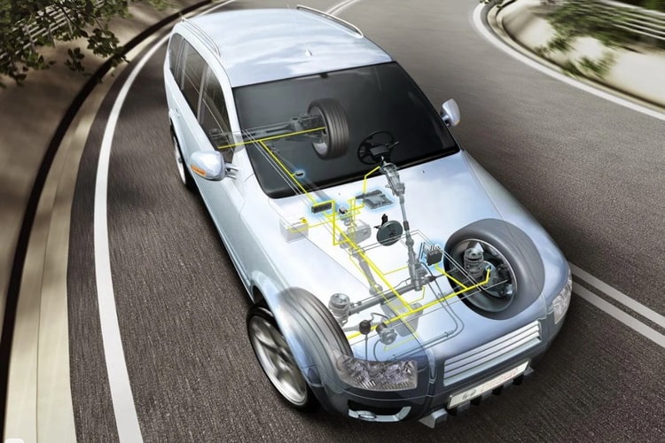
В ходе развития техники появились многоканальные системы с добавочным интеллектом, позволяющие предсказывать ситуацию и более точно управлять торможением, раздавая давление на каждое колесо строго дозированно, учитывая его положение и условия работы.
Конструкция получила аббревиатуру EBD, то есть Electronic Brakeforce Distribution, распределение тормозных усилий.
Для чего в машине система EBD
Принцип работы обычной ABS из первых воплощений подразумевает наличие единого канала управления. На каждом колесе имеется датчик скорости вращения, показания которого в виде частоты электрических импульсов передаются по кабелям в общий электронный блок, где кодируются в цифровую информацию и обрабатываются микрокомпьютером.
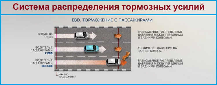
Прибор анализирует все поступившие данные и определяет скорость движения автомобиля. Заметив начало торможения, он приступает к оценке отклонений частоты вращения отдельных колёс, фиксируя таким образом начало их проскальзывания из-за превышения предела сцепления с дорогой.
Поскольку эффективность замедления в случае перехода в скольжение сильно ухудшается, что дополнительно может быть отмечено по сигналам датчика линейного ускорения автомобиля, принимается решение на регулирование давления в тормозной магистрали.
Читайте также: Назначение и принцип работы системы ESP
В состав системы входят следующие устройства:
- датчики вращения колёс, обычно индукционные или те, что работают за счет эффекта Холла;
- электронный блок обработки данных и управления исполнительными механизмами;
- гидравлический блок с насосом тормозной жидкости, ресивером-аккумулятором давления, входными и выходными электрогидравлическими клапанами;
- раздельные тормозные магистрали по осям или отдельным колёсам;
- тормозная педаль и связанный с нею главный тормозной цилиндр;
- рабочие колёсные тормозные цилиндры.
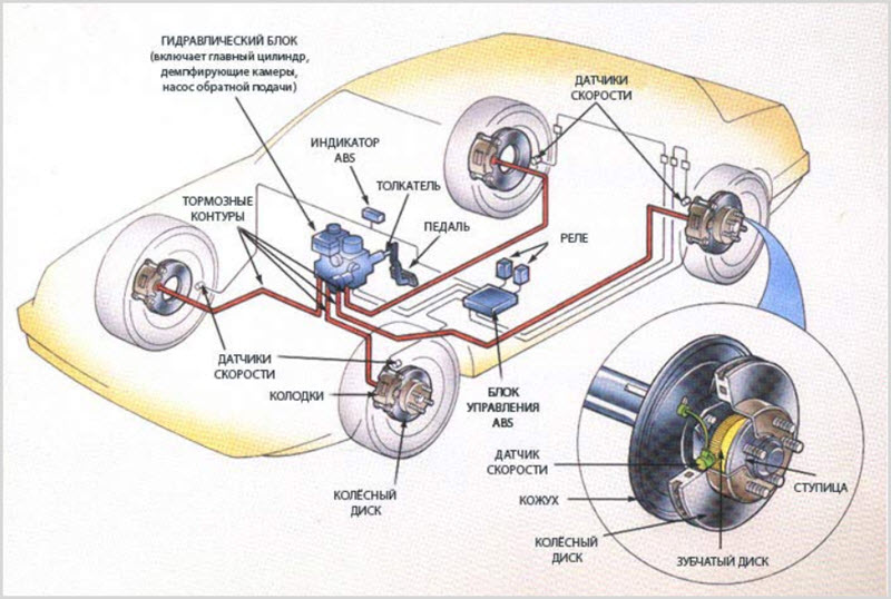
Подобная организация антиблокировочной системы позволяет решить задачу стабильности и частично оптимизировать торможение, но достигается это ценой неминуемого увеличения тормозного пути в некоторых условиях.
Не учитываются особенности загрузки автомобиля, распределения массы по осям, а также динамического перераспределения веса.
Дополнением к ABS стала система распределения тормозных усилий, позволяющая почти полностью решить проблему. Достигнуто это было применением четырёхканального управления раздельно по колёсам, и более точного прогноза поведения автомобиля.
Таким образом, EBD можно считать усовершенствованной ABS, учитывающей больший объём информации и располагающей дополнительными возможностями по индивидуальному управлению каждым тормозным цилиндром или их кластерами.
Принцип работы системы распределения тормозных усилий
EBD, в отличие от ABS, работает ещё до того, как началось скольжение. Система располагает данными о загрузке осей, полученными в процессе работы и умеет управлять усилиями.
Например, если основная масса машины приходится на переднюю ось, то есть зад машины не нагружен, то естественный эффект динамического перераспределения веса машины вперёд при торможении будет усугубляться лёгкой задней осью.
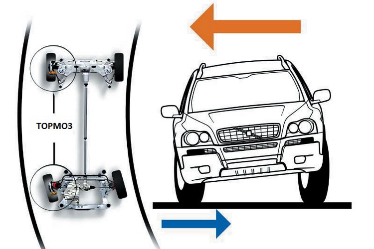
В условиях экстренного торможения на скользком покрытии задние колёса начнут блокироваться слишком рано, результатом станет снижение давления во всей системе и возможности хорошо нагруженных передних колёс не будут реализованы. Тормозной путь устремится в бесконечность.
Ещё хуже ситуация может возникнуть в повороте на неровной дороге. Водителей старых автомобилей, не оборудованных тормозной электроникой, даже учили, что тормозить в повороте категорически не рекомендуется, а что происходит при подбросе колёс на ухабах во время нажатия на тормозную педаль они могли заметить сами и запомнить на всю жизнь.
Антиблокировочные системы очень облегчили управление, теперь торможение в повороте стало не только возможным, но и рекомендуемым действием.
Статья по теме: Что такое атермальное остекление в автомобиле
В сложных условиях неопытному водителю надо было только нажать на тормоз с максимальным усилием и дальше корректировать машину только рулевым колесом, нужное сцепление обеспечит автоматика.
Роль EBD во всех этих случаях заключалась в минимизации тормозного пути. Если передние колёса при обычном торможении имеют запас по сцеплению, когда задние уже заблокировались и подвергнуты обслуживанию со стороны ABS, то будет очень нерационально сбрасывать давление и с них тоже.
Наоборот, надо добавить усилие на переднюю ось, не сбрасывать его равномерно со всех колёс, а перераспределить. Четырёхканальные системы на это способны, а соответствующая программа управления электронным блоком и стала основой EBD.
То же самое и в повороте. Внутренние колёса могут настолько разгрузиться из-за центробежной силы, что буквально поднимаются в воздух. Естественно, при попытке торможения они мгновенно заблокируются, поскольку сила сцепления близка к нулю.
ABS отреагировала бы на ситуацию полным прекращением торможения, то есть поступила бы как водитель старой школы.
Но EBD гораздо умнее, она способна не только исключить блокировку разгруженных колёс внутренней по отношению к повороту стороны автомобиля, но и увеличить давление в тормозных цилиндрах внешней, загруженной стороны.
Это надо знать: Как проверить Датчик Массового Расхода Воздуха (ДМРВ)
Машина начнёт достаточно эффективно замедляться, что в ситуациях с превышением скорости в повороте может спасти и технику, и водителя с пассажирами.
Возможны и другие ситуации, когда раздельное управление с прогнозированием может помочь быстро остановить автомобиль:
- торможение на дороге с неоднородным покрытием, когда коэффициент сцепления для всех колёс сильно различается, это попадание в лужи, локальную грязь или пятна льда;
- начало вращения автомобиля, некоторые колёса ещё способны к торможению, когда прочие уже скользят и неуправляемы;
- кратковременные подбросы колёс на неровностях;
- неисправности или загрязнения в тормозной системе, когда имеются различия в эффективности колёсных тормозных механизмов.
Принцип помощи водителю со стороны EBD именно в том и состоит, что добавляется ранее недоступная ему функция раздельного обслуживания колёс при торможении.
Это интересно: Что лучше полный привод, передний или задний
Если раньше он мог в какой-то степени имитировать работу ABS прерывистым нажатием на педаль, то уж управление тормозным балансом было доступно только в отдельных гоночных сериях, где самые опытные пилоты управляют сложными и дорогими автомобилями.
С появлением EBD это стало доступным каждому, причём без каких-либо особых навыков и знаний.
Устройство системы
Регулирование тормозного усилия раздельно по всем колёсам в первую очередь потребует применения многоканальной антиблокировочной системы.
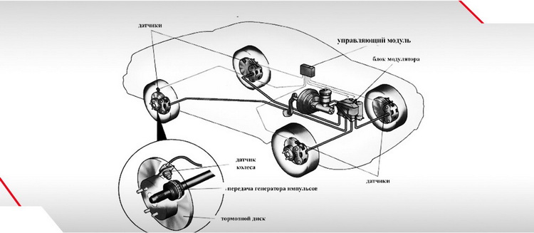
Отсюда и формируется состав EBD:
- индивидуальные датчики на каждое колесо;
- впускные и выпускные клапаны, открывающие давление жидкости на рабочие цилиндры, фиксирующие его неизменным или сбрасывающие усилие;
- электрический насос тормозной жидкости, способный быстро изменять давление в системе;
- гидравлический аккумулятор давления, оптимизирующий работу насоса;
- специальная управляющая программа, которая, собственно, и составляет основу EBD, отличая её от четырёхканальной ABS;
- дополнительные датчики, расширяющие возможности системы, они могут входить в состав бортовой электроники более высокого уровня, чем отвечающей только за тормоза.
Точные алгоритмы работы EBD разных производителей по понятным причинам не афишируются, но можно выделить общие алгоритмы, образующие модель EBD в программной памяти её компьютера.
Существует некое пороговое условие, за которым EBD оживает из ждущего режима и включается в работу тормозов. Это условие формируется по результатам непрерывного анализа поступающей от датчиков информации.
К сведению: Что такое тормозной суппорт и как он работает
Как только блок поймёт, что существует вероятность блокировки колёс, он переходит в режим фиксации давления, в результате чего перекрываются оба клапана на каждом колесе, давление стабилизируется.
Дальше оценивается развитие ситуации и подаются команды на открытие или закрытие отдельных клапанов, давление увеличивается или уменьшается, происходит импульсное регулирование торможения на грани блокировки, то есть самое эффективное.
Признаки неисправности EBD
Любой отказ системы приводит к ухудшению торможения в экстренной ситуации, что вряд ли может быть замечено водителем. Поэтому единственным признаком неисправности является зажигание контрольной лампочки на приборной панели.
Появление этого сигнала требует немедленной диагностики специальным сканером с выявлением кодов ошибки и устранением неисправностей.
Система очень надёжна, поэтому самой частой неисправностью бывает отказ колёсных датчиков. Это связано с их работой в тяжёлых условиях по влажности и загрязнённости.
Рекомендуем: Как установить камеру заднего вида на автомобиль (схема подключения)
Коррозия и механические поломки приводят к пропаданию сигнала, что немедленно будет замечено электронным блоком, и появится индикация контрольной лампы. Проверка достаточно проста для диагностики, ремонт сводится к замене датчика или ревизии его проводки.
Плюсы и минусы
Соотношение достоинств и недостатков EBD сильно зависит от конкретного исполнения, система непрерывно совершенствуется, количество версий уже давно перевалило через десяток.
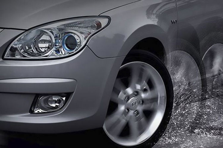
Достоинства:
- уменьшается тормозной путь, даже по сравнению с ABS;
- машина стабильно ведёт себя при торможении в повороте;
- характер замедления меньше зависит от загрузки автомобиля, что особенно важно для коммерческого транспорта;
- минимизируется набор условий, при котором может возникнуть занос при торможении.
Недостатки:
- возможны ситуации, когда срабатывание системы удлиняет тормозной путь, вплоть до ощущения полного отказа тормозов, ведь случаются ситуации, в которых более эффективно машина замедляется именно в скольжении, а его EBD призвана исключать;
- не до конца отработаны алгоритмы работы на автомобилях с полным приводом, такие шасси могут создавать проблемы даже опытным водителям;
- система недостаточно совершенна для работы на скользких склонах, поэтому до сих пор она автоматически отключается в таких условиях на малых скоростях.
Каждая ситуация, в которой EBD раскрывает свои возможности недостаточно полно, анализируется, и в алгоритмы её работы вносятся коррективы.
Кроме того, с развитием техники идёт повышение быстродействия работы её элементов. Поэтому каждая последующая версия имеет всё меньше недостатков, а достоинства не оспариваются.
![]()
|
Запуск двигателя и вождение |
83 |
Трогание с места на задней передаче
Чтобы включить заднюю передачу (если она не была включена прежде), переведите рычаг управления в положение R. Включение заднего хода будет подтверждено символом на дисплее и звуковым сигналом.
Чтобы тронуться с места, плавно нажимайте на педаль акселератора.
ПРИМЕЧАНИЕ: Для ускорения маневрирования в случаях, когда требуется частое переключение между первой и задней передачами, предусмотрена возможность включения заднего хода на не полностью остановленном автомобиле.
Движение вперед в ручном режиме: переключение передач
Чтобы включить передачу переднего хода (если она не была включена ранее), переведите рычаг управления в среднее положение. На
дисплее появится символ А1 или М1.
При этом для выбора ручного режима (если он еще не выбран) переведите рычаг влево (или вперед, или назад) и сразу отпустите. На дисплее появится символ М1.
Чтобы тронуться с места, плавно нажимайте на педаль акселератора.
Чтобы переключиться на более высокую передачу, необходимо, удерживая педаль акселератора в одном положении, сдвинуть рычаг на зад (в положение +) и сразу отпустить, при этом «сопровождая» рычаг рукой. Система выполнит переключение передач, и на дисплее вы светится номер включенной передачи.
Чтобы переключиться на низшую передачу, необходимо, удерживая педаль акселератора в одном положении, сдвинуть рычаг вперед (в положение –) и сразу отпустить, при этом «сопровождая» рычаг рукой.
Для перехода на несколько передач вверх или вниз необходимо быстро переместить рычаг два или более раз назад или вперед.
При этом система проверяет, не будут ли обороты двигателя при включении требуемой передачи превышать максимально допустимого значения. Если это может произойти (т. е. имеется опасность превысить допустимые обороты), передача включена не будет.
ПРИМЕЧАНИЕ: Переключиться в автоматический режим можно в любой момент, переместив рычаг влево (в положение А/М) и сразу отпустив его.
Предупреждение!
Несмотря на то, что в памяти систе мы хранятся практически все параме
Переключение передач переднего тры, она не может прогнозировать
хода в автоматическом режиме состояние приближающегося участка Чтобы включить передачу переднего дороги или условия движения. Реко
хода (если она не была включена ра мендуем водителю самостоятельно
нее), переведите рычаг управления в принимать решение о том, когда сле среднее положение. На дисплее по дует переходить на ручной режим уп явится символ А1 или М1. равления коробкой передач.
При этом для выбора автоматическо Это можно сделать не переключая передачу (переместив рычаг влево, в
го режима (если он еще не выбран) положение А/М), либо принудитель переведите рычаг влево и сразу отпу но переключив передачу (переместив стите его. На дисплее появится сим рычаг вперед или назад): в положе вол А1. ния – или +).
В автоматическом режиме система автоматически выбирает передачу, лучше всего соответствующую услови
ям движения (уклону дороги, нагрузке) и стилю вождения (последнее определяется в зависимости от частоты и интенсивности нажатия на педаль акселератора). Тем самым обеспечиваются наилучшие динамические показатели автомобиля. Одно временно с этим уменьшается расхода топлива и обеспечивается максимальный комфорт.
Поэтому для движения в наиболее экономичном режиме необходимо плавно нажи мать на педаль акселератора примерно на 50 60% хода. Не следует нажимать на педаль до упора.
В любой момент водитель может принудительно переключить передачу, переместив рычаг управления вперед (для перехода на низшую передачу) или назад (для пере хода на высшую передачу). При этом коробка передач автоматически переходит в ручной режим работы (М).
84 Запуск двигателя и вождение

|
Предупреждение! |
Запуск двигателя и вождение |
85 |
Программирование скорости (круиз контроль)
Указания по пользованию круиз кон тролем приведены в соответствующем разделе брошюры «Эксплуатация и техническое обслуживание».
На некоторых модификациях уста навливается коробка отбора мощно сти. В целях безопасности система управления коробкой передач снаб жена функцией, позволяющей рас познавать включение коробки отбо ра мощности.
Разница для автоматизированной коробки передач состоит только в том, что при выключении сцепления круиз контроль не отключается.
Поэтому поддержание заданной скорости возможно без помощи педали акселе ратора:
■переключение передач (в ручном режиме) — переместите рычаг управления вперед и назад;
■если по условиям движения (изменение продольного уклона дороги) требуется дополнительное переключение передач, производите его.
Использование коробки отбора мощности (если установлено)
Указания по пользованию коробкой отбора мощности приведены в соответствую щем разделе брошюры «Эксплуатация и техническое обслуживание».
Отбор мощности (постоянный или временный) можно включить (нажатием соответ ствующих кнопок) только при работающем двигателе и включенной нейтральной передаче в коробке передач (рычаг в положении N).
После включения временного отбора мощности можно включить передачу и тро нуться с места.
ПРИМЕЧАНИЕ: При включении коробки отбора мощности переключение передач на движущемся автомобиле невозможно.
Выключить отбор мощности можно как при движении на передаче, так и на нейтрали.

86 Запуск двигателя и вождение
Сигнализация неисправностей
При возникновении неисправностей в системе на дисплее появляется символ раз водного ключа. В наиболее серьезных случаях дополнительно включается прерыви стый звуковой сигнал.
При возникновении неисправности блок управления коробки передач управляет (в зависимости от серьезности неисправности) поврежденной функцией, обеспечивая реализацию максимально возможного набора функций системы, с учетом следую щих требований:
■обеспечение безопасности водителя и пассажира, а также недопущение ухуд шения состояния двигателя и коробки передач.
При возникновении любой неисправности рекомендуется:
■остановить автомобиль в безопасном месте, остановить двигатель и вновь за пустить его. Если на дисплее вновь появится символ разводного ключа, повто рите процедуру, выждав перед повторным запуском двигателя не менее 40 се кунд.
Если символ неисправности не исчезает, но автомобиль способен продолжать дви жение, двигайтесь к ближайшей специализированной станции технического обслу живания, соблюдая при этом меры предосторожности.
Если автомобиль не может двигаться, свяжитесь с официальным дилером либо по звоните в бесплатную круглосуточную службу сервиса, чтобы обеспечить доставку автомобиля на станцию технического обслуживания.

Буксировка автомобиля
См. указания, изложенные в соответ ствующем разделе «Руководства по эксплуатации и техническому обслу живанию».
|
Предупреждение! |
Запуск двигателя и вождение |
87 |
Описываемые маневры представляют опасность и должны выполняться толь ко специализированным персоналом, знающим все меры предосторожнос ти, которые необходимо предпринять во избежание получения травм и по вреждения техники!
Запуск двигателя «с буксира» не ре комендуется, но допускается, если аккумуляторная батарея достаточно заряжена
для запуска двигателя и работы приводов коробки передач и сцепления (об этом свидетельствует свечение дисплея).
Чтобы запустить двигатель таким способом:
■Вставьте ключ в замок зажигания, поверните его по часовой стрелке в поло жение I (MAR); по дисплею начнет перемещаться слово BRAKE.
■Нажмите на педаль тормоза и удерживайте ее, примерно через 3 секунды на дисплее появится сообщение ОК (система выполнила самопроверку и авто матически выключила сцепление), после чего (также примерно через 3 секун ды) высветится режим и передача, включенные ранее (N, M1, A1 или R).
■Включите первую передачу в ручном режиме (на дисплее появится М1).
■После этого можно буксировать автомобиль. Через 10 секунд после начала движения система автоматически включит сцепление.
■В течение 10 секунд после начала движения с помощью рычага управления включите 2 ю или 3 ю передачу (на дисплее должно появиться М2 или М3).

Важное замечание!
После преодоления труднопроходи мого участка дороги:
■ Продолжая движение на автомо биле, выключите блокировку диф ференциала.
■ Кратковременно увеличьте часто ту вращения двигателя.
■ Выберите скорость в соответствии с условиями движения.
Если блокировка не выключится сра зу, следует попытаться изменить на правление движения, чтобы снять на пряжения в дифференциале.
88 Запуск двигателя и вождение
Включение блокировки дифференциала заднего моста (если установлено)
Включать блокировку дифференциала допускается только тогда, когда авто мобиль либо стоит, либо движется на очень малой скорости. Для включения блокировки нажмите кнопку со встро енной контрольной лампой, располо женную в блоке выключателей.
Как только будет возможно движение автомобиля с разблокированным
дифференциалом, нажмите кнопку еще раз. Блокировка дифференциала заднего моста выключится, контрольная лампа погаснет.

|
Важное замечание! |
Запуск двигателя и вождение |
89 |
Предупреждение:
■Блокировкой дифференциала сле дует пользоваться только при дви жении по грязи или скользкому грунту.
■Мигание контрольной лампы гово рит о слишком высокой скорости: выключите блокировку дифферен циала или снизьте скорость дви жения. Если дифференциал не разблокируется сразу, следует не сколько раз повернуть руль влево вправо.
■Если на автомобиле имеется анти блокировочная система тормозов (ABS), пользоваться блокировкой дифференциала следует осторож но, поскольку она может повлиять на эффективность работы ABS (см. следующую страницу).
■На грязной и скользкой поверхно сти не давайте колесам буксовать с выключенной блокировкой диф ференциала заднего моста даже в течение нескольких секунд, так как это может привести к поломке.
■Не включайте блокировку диффе ренциала, когда одно из колес пробуксовывает. Выключайте бло кировку дифференциала при дви жении по мощеным дорогам; в этом случае движение с заблоки рованным дифференциалом мо жет привести к серьезному по вреждению шестерен.
Возможно серьезное поврежде ние: помните, что при движении с включенной блокировкой диффе ренциала маневренность автомо биля ухудшается.

Возможно серьезное повреждение: Неисправность антиблокировочной систем тормозов ABS и электронной системы распределения тормозных сил (EBD) может привести к измене нию поведения автомобиля, при этом торможение происходит без участия этих систем.
При первой же возможности обрати тесь на специализированную стан цию технического обслуживания.
90 Запуск двигателя и вождение
Антиблокировочная система тормозов (ABS)/Клапан ограничения давления (EBD)/Система контроля сцепления шин с дорогой (ABD)
Придерживайтесь следующих указаний: ■ Помните, что при торможении пе даль тормоза может слегка вибри
ровать: это означает, что включи лась система ABS.
■Хотя система и обеспечивает мак симальную активную безопас
ность, водите автомобиль осторожно, избегайте неоправданных рисков.
■Стиль вождения должен соответствовать погоде, состоянию дороги и условиям движения.
■Помните, что замедление автомобиля при торможении зависит от сцепления шин с дорогой. Если на дороге снег или лед, сцепление минимально. Не забы вайте, что в таких условиях тормозной путь увеличивается, даже при безу пречно работающей ABS.
■Одновременное включение контрольных ламп ABS и EBD свидетельствует о наличии неполадок в системе ABS. Избегайте резких торможений — они могут привести к блокировке колес и, как следствие, к заносу автомобиля. Если включается только контрольная лампа ABS, клапан ограничения давления (EBD) продолжает работать, а системы ABS и ABD отключаются. В такой ситу ации следует осторожно, избегая резких торможений, доехать до ближайшей станции технического обслуживания, чтобы проверить работу систем.

|
Запуск двигателя и вождение |
91 |
■Мигание контрольной лампы системы контроля сцепления шин с дорогой (ABD) указывает на включение системы (контрольная лампа будет продолжать мигать, пока автомобиль не разгонится до скорости 40 км/час).
Контрольная лампа ABD включается в следующих случаях:
1.Неисправность в системе.
2.Временное выключение системы вследствие слишком долгой работы.
По прошествии некоторого времени система снова включится.
ДЛЯ АВТОМОБИЛЕЙ, ОСНАЩЕННЫХ УСТРОЙСТВОМ БЛОКИРОВКИ ДИФ ФЕРЕНЦИАЛА ЗАДНЕГО МОСТА:
■В определенных условиях торможение с заблокированным дифференциалом заднего моста может привести к снижению устойчивости автомобиля. В этом случае рекомендуется применять только обычное торможение, даже при нали чии на автомобиле ABS.
92 Запуск двигателя и вождение
ESP8 — электронная система обеспечения курсовой устойчивости (если установлено)
Эта система с помощью датчика поворота рулевого колеса определяет требуемое водителем направление движения, и на основании данных датчика угла поворота автомобиля и датчиков скорости вращения колес сравнивает его с реальным кур сом автомобиля. Если автомобиль теряет курсовую устойчивость, система подтор маживает отдельные колеса и уменьшает обороты двигателя.
В системе реализуются следующие функции:
■контроль сцепления с дорогой;
■контроль курсовой устойчивости;
■помощь при трогании на подъем.
ASR — контроль сцепления с дорогой при разгоне (входит в состав ESP) Эта система быстро воздействует на двигатель и тормозные механизмы, предот вращая пробуксовку ведущих колес. Она позволяет автомобилю быстро и безо пасно трогаться с места даже скользкой дороге или при пробуксовке ведущих ко
лес. Другими словами, она снижает опасность заноса при прохождении поворота со слишком высокой скоростью. На пульте, находящемся перед водителем, имеется кнопка отключения системы. Однако система автоматически включается, когда скорость превышает 40 км/ч. Систему ASR необходимо отключать при установке цепей противоскольжения, а также если колеса проваливаются в грунт (песок, мел кий щебень и т. д.).
О включении обеих систем сигнализирует желтая контрольная лампа, изображен ная на рисунке. При нормальной работе систем она мигает, а в случае неисправ ности ASR/ESP горит непрерывно.
Соседние файлы в предмете [НЕСОРТИРОВАННОЕ]
- #
- #
- #
- #
- #
- #
- #
- #
- #
- #
- #

15
Кабина
* Бортовой компьютер автоматически
проверяет работоспособность кон
трольных ламп, помеченных звез
дочкой. Поэтому при каждом запус
ке двигателя они загораются на не
сколько секунд.
Некоторые контрольные лампы, от
вечающие за функции дополнитель
ного оборудования, могут быть не
установлены на Вашем автомоби
ле — это зависит от комплектации.
1
Только для модификации Combi с
двигателем 12 F1A и модификаций,
оснащенных двигателем F1C Euro.
Обозначение
Описание
15
1
Контрольная лампа неисправности системы рециркуляции
отработанных газов EGR (красная).
16
Контрольная лампа иммобилайзера (желтая).
17
Контрольная лампа противотуманных фар (зеленая).
18
Контрольная лампа «Открыта дверь» (красная).
19
Контрольная лампа неисправности подушки безопасности (красная).
20
Контрольная лампа неисправности электронной системы
распределения тормозных сил (EBD) (красная).
21
*Контрольная лампа неисправности механизма боковой
сдвижной двери (красная).
22
Контрольная лампа включения ретардера (желтая).
23
*Контрольная лампа присутствия воды/засорения топливного
фильтра (желтая).
24
*Контрольная лампа засорения воздушного фильтра (желтая).
25
Контрольная лампа неисправности системы впрыска EDC (красная).
26
Контрольная лампа включения предпускового прогрева
двигателя (желтая).
27
Контрольная лампа неисправности электронной системы
распределения тормозных сил (EBD 5.3) (красная).
28
*Контрольная лампа неисправности системы ABS 5.3 (желтая).

17
Кабина
* Бортовой компьютер автоматически
проверяет работоспособность кон
трольных ламп, помеченных звез
дочкой. Поэтому при каждом запус
ке двигателя они загораются на не
сколько секунд.
Некоторые контрольные лампы, от
вечающие за функции дополнитель
ного оборудования, могут быть не
установлены на Вашем автомоби
ле — это зависит от комплектации.
Обозначение
Описание
29
Контрольная лампа неисправности пневматической подвески с
электронной системой управления ECAS (красная).
30
Контрольная лампа блокировки дифференциала заднего моста
(красная).
31
*Контрольная лампа недостаточного уровня жидкости в системе
охлаждения двигателя (красная).
32
*Контрольная лампа системы контроля тягового усилия (ABD)
(желтая).

18
Кабина
Кнопочный пульт управления
Описание
Символ
Контрольная лампа аварийной сигнализации.
Противотуманные фары.
Выключатель обогрева зеркал заднего вида.
Обогрев заднего стекла.
Блокировка дифференциала заднего моста.
Пневматическая подвеска ECAS (выравнивание).
Пневматическая подвеска ECAS (опускание).
Пневматическая подвеска ECAS (подъем).
Во время диагностики своего транспортного средства компьютер в случае неисправностей получает код ошибки, которая может быть расшифрована специалистом. Здесь представлены некоторые варианты кодов ошибок и их значений.
Неисправности датчиков скорости и педалей, датчиков давления топлива, цепей управления форсунками, контроллеров, иммобилайзера и многого другого.
Приезжайте к нам для полной диагностики Вашего автомобиля Iveco по адресу: г. Минск, ул. Монтажников 51, корп. 1
✆ +375 29 186 00 59 ✆ +375 33 676 00 59
|
0111 |
Неисправность цепи датчика скорости автомобиля |
|
0112 |
Неисправность цепи датчика 1 положения педали ускорения |
|
0113 |
Несоответствие сигналов выключателей тормоза и датчиков педали ускорения |
|
0116 |
Неисправность цепи выключателя педали сцепления |
|
0117 |
Некорректный сигнал выключателей педали тормоза |
|
0119 |
Пропадание напряжения бортовой сети на контроллере от клеммы «15» |
|
0122 |
Неисправность цепи управления лампой MIL (Check Engine) |
|
0126 |
Напряжение бортовой сети вне рабочего диапазона контроллера |
|
0131 |
Неисправность цепи датчика температуры охлаждающей жидкости |
|
0132 |
Некорректный сигнал цепи датчика температуры охлаждающей жидкости |
|
0133 |
Неисправность цепи датчика температуры воздуха на впуске |
|
0134 |
Неисправность цепи датчика давления наддувочного воздуха |
|
0135 |
Неисправность цепи датчика температуры топлива |
|
0136 |
Неисправность цепи датчика давления топлива в рампе |
|
013A |
Неисправность цепи датчика температуры масла |
|
013E |
Низкий уровень сигнала в цепи датчика давления охлаждающей жидкости |
|
013F |
Некорректный сигнал в цепи давления охлаждающей жидкости |
|
0141 |
Неисправность или обрыв цепи датчика (частоты) положения коленчатого вала |
|
0143 |
Неисправность цепи датчика (фазы) положения распределительного вала |
|
0144 |
Несоответствие сигналов датчиков синхронизации (частоты и фазы) |
|
0145 |
Неисправность цепи управления реле электровентилятора 1 |
|
0149 |
Неисправность цепи нагревателя топлива |
|
014D |
Предельно-допустимая частота вращения коленчатого вала двигателя |
|
0151 |
Высокий уровень сигнала цепи датчика давления топлива в рампе |
|
0152 |
Повышенное давление топлива в рампе |
|
0153 |
Пониженное давление топлива в рампе |
|
0154 |
Давление топлива в рампе выше максимально допустимого |
|
0155 |
Давление топлива в рампе ниже минимально допустимого |
|
0159 |
Неисправность цепи топливного насоса высокого давления (ТНВД) |
|
015C |
Некорректное время впрыска топлива для форсунки цилиндра 1 |
|
015D |
Некорректное время впрыска топлива для форсунки цилиндра 3 |
|
015E |
Некорректное время впрыска топлива для форсунки цилиндра 5 |
|
015F |
Неисправность топливной системы, влияющая на токсичные выбросы |
|
0161 |
Неисправность цепи управления форсункой 1 |
|
0162 |
Неисправность цепи управления форсункой 2 |
|
0163 |
Неисправность цепи управления форсункой 3 |
|
0164 |
Неисправность цепи управления форсункой 4 |
|
0165 |
Неисправность цепи управления форсункой 5 |
|
0166 |
Неисправность цепи управления форсункой 6 |
|
0167 |
Обрыв или короткое замыкание на «массу» цепи управления форсункой 4 |
|
0168 |
Неисправность цепи управления форсункой 1 |
|
0169 |
Неисправность цепи управления форсункой 1 |
|
016A |
Неисправность цепи управления форсункой 1 |
|
016B |
Неисправность цепи управления форсункой 1 |
|
016C |
Предельное падение крутящего момента в цилиндре 1 |
|
016E |
Минимально необходимое количество впрысков не выполнено |
|
0171 |
Неисправность канала 1 управления форсунками |
|
0173 |
Неисправность канала 2 управления форсунками |
|
017C |
Контроллер: Неисправность канала (драйвера) 1 управления форсунками |
|
017D |
Общая неисправность системы сгорания топливовоздушной смеси |
|
017F |
Контроллер: некорректная запись или отсутствие записи IMA-кодов форсунок |
|
0182 |
Неисправность цепи датчика температуры воздуха на впуске (ДМРВ) |
|
0183 |
Низкий уровень сигнала в цепи датчика массового расхода воздуха |
|
0185 |
Высокий уровень сигнала в цепи датчика массового расхода воздуха |
|
0187 |
Повышенный расход воздуха через клапан рециркуляции ОГ |
|
0188 |
Пониженный расход воздуха через клапан рециркуляции ОГ |
|
0189 |
Короткое замыкание на бортовую сеть цепи управления клапаном рециркуляции |
|
018B |
КЗ на бортовую сеть цепи управления дросселем клапана рециркуляции ОГ |
|
018C |
Система топливоподачи слишком «бедная» при ее максимальном обогащении |
|
018D |
Токсичные выбросы окислов азота (NOx) выше первого порога |
|
0192 |
Короткое замыкание на бортовую сеть цепи управления турбокомпрессором |
|
0194 |
Повышенная производительность (мощность) турбокомпрессора |
|
0195 |
Пониженная производительность (мощность) турбокомпрессора |
|
019E |
Ограничение вращающего момента, вызванное неисправностями систем ДВС |
|
01A8 |
Предельно-допустимая температура дозирующего клапана мочевины |
|
01B1 |
Обрыв информационной CAN-линии «Н» |
|
01B3 |
Обрыв информационной CAN-линии «L» |
|
01B7 |
Информационная CAN-шина занята |
|
01BA |
CAN-шина: нет ответа от комбинации приборов автомобиля |
|
01C3 |
CAN-шина: нет ответа от тахографа |
|
01D1 |
Контроллер: неисправность SPI-канала |
|
01D2 |
Контроллер: неисправность EEPROM-памяти |
|
01D3 |
Контроллер: заблокирован для пуска двигателя |
|
01D4 |
Контроллер: неисправность микропрограммы перезагрузки |
|
01D5 |
Контроллер: ошибка программы инициализации |
|
01D6 |
Контроллер: ошибка внутренней синхронизации |
|
01D7 |
Контроллер: некорректный вариант калибровок управления двигателем |
|
01D8 |
Контроллер: неисправность микропрограммы перезагрузки |
|
01D9 |
Контроллер: неисправность аналого-цифрового преобразователя сигналов |
|
01DA |
Контроллер: неисправность флэш-ПЗУ (ошибка контрольной суммы) |
|
03D3 |
Контроллер: ошибка программы инициализации |
|
01E2 |
Иммобилайзер: неисправность блока или его цепей (топливоподача блокирована) |
|
01E3 |
Ошибка программы мониторинга систем двигателя |
|
01E4 |
Повышенная частота вращения коленчатого вала двигателя |
|
01E6 |
Контроллер: напряжение типа 1 для питания датчиков вне диапазона |
|
01E7 |
Контроллер: напряжение типа 2 для питания датчиков вне диапазона |
|
01E8 |
Контроллер: напряжение типа 3 для питания датчиков вне диапазона |
|
01E9 |
Контроллер: напряжение питания выше допустимого |
|
01EA |
Контроллер: напряжение питания ниже допустимого |
|
01EB |
Неисправность цепи датчика атмосферного (абсолютного) давления воздуха |
|
01F1 |
Неисправность цепи датчика засоренности сажевого фильтра |
|
01F2 |
Некорректный сигнал в цепи датчика засоренности сажевого фильтра |
|
01F3 |
Неисправность цепи датчика засоренности сажевого фильтра фильтра |
|
01F4 |
Низкий уровень сигнала в цепи датчика засоренности сажевого фильтра |
|
01F5 |
Высокий уровень сигнала цепи датчика засоренности сажевого фильтра |
|
01F6 |
Неисправность датчика температуры ОГ до нейтрализатора |
|
01F7 |
Неисправность цепи датчика температуры отработавших газов |
|
01F8 |
Некорректный сигнал в цепи датчика температуры отработавших газов |
|
01F9 |
Высокий уровень регенерации сажевого фильтра |
|
01FA |
Низкий уровень регенерации сажевого фильтра |
|
01FB |
Эффективность нейтрализатора ниже допустимой нормы |
|
01FC |
Медленный отклик на изменение температуры датчика до нейтрализатора |
|
0212 |
Неисправность цепи датчика 2 положения педали ускорения |
|
0215 |
Неустранимый отказ системы автоматического бортового контроля |
|
0225 |
Неисправность цепи управления главным реле |
|
022B |
Неисправность силовой цепи свечей накаливания |
|
022E |
Неисправность цепи управления реле подкачивающего электробензонасоса |
|
0232 |
Сигнал датчика температуры охлаждающей жидкости вне диапазона |
|
0236 |
Некорректный сигнал в цепи датчика давления топлива в рампе при останове ДВС |
|
023A |
Высокий уровень сигнала в цепи датчика температуры масла |
|
0251 |
Повышенное давление топлива в рампе |
|
0259 |
Короткое замыкание на бортовую сеть цепи управления ТНВД |
|
025C |
Некорректное время впрыска топлива для форсунки цилиндра 2 |
|
025D |
Некорректное время впрыска топлива для форсунки цилиндра 4 |
|
025E |
Некорректное время впрыска топлива для форсунки цилиндра 6 |
|
025F |
Неисправность системы впрыска топлива, влияющая на выбросы NOx |
|
0275 |
Некачественное сгорание топливовоздушной смеси в цилиндре 1 |
|
0276 |
Некачественное сгорание топливовоздушной смеси в цилиндре 2 |
|
0277 |
Некачественное сгорание топливовоздушной смеси в цилиндре 3 |
|
0278 |
Некачественное сгорание топливовоздушной смеси в цилиндре 4 |
|
0279 |
Некачественное сгорание топливовоздушной смеси в цилиндре 5 |
|
027A |
Некачественное сгорание топливовоздушной смеси в цилиндре 6 |
|
027C |
Контроллер: Неисправность канала (драйвера) 2 управления форсунками |
|
0281 |
Недостоверный расход воздуха через клапан рециркуляции ОГ |
|
0283 |
Предельно допустимое отклонение расхода воздуха на рабочем режиме |
|
0285 |
Предельно допустимое отклонение расхода воздуха на холостом ходу |
|
0286 |
Сигнал датчика массового расхода воздуха вне допустимого диапазона |
|
0287 |
Повышенный расход воздуха через клапан рециркуляции ОГ |
|
0288 |
Пониженный расход воздуха через клапан рециркуляции ОГ |
|
0289 |
Короткое замыкание на «массу» цепи управления клапаном рециркуляции ОГ |
|
028B |
КЗ на «массу» цепи управления дросселем клапана рециркуляции ОГ |
|
0292 |
Обрыв или КЗ на «массу» цепи управления турбокомпрессором |
|
02B4 |
CAN-шина: нет ответа от маршрутного компьютера или тестового оборудования |
|
02C9 |
CAN-шина: неверные данные от комбинации приборов или тахографа |
|
02F8 |
Некорректный сигнал в цепи датчика температуры отработавших газов |
|
02FF |
Критическое время впрыска для растворения масла в цилиндре двигателя |
|
0315 |
Устранимый отказ системы автоматического бортового контроля |
|
032B |
Неисправность цепи управления реле свечами накаливания |
|
0359 |
Короткое замыкание на «массу» цепи управления ТНВД |
|
035F |
Неисправность системы питания воздухом, влияющая на токсичные выбросы |
|
0385 |
Предельно допустимое отклонение расхода воздуха на нагрузочном режиме |
|
0386 |
Сигнал датчика массового расхода воздуха вне допустимого диапазона |
|
0389 |
Открытое состояние клапана рециркуляции или повышенная температура ОГ |
|
038B |
Открытое состояние дросселя КРЦ или повышенная температура ОГ |
|
0392 |
КЗ на бортовую сеть цепи управления турбокомпрессором и высокая температура |
|
039D |
Вероятное превышение норм токсичных выбросов (OBD) — богатая смесь |
|
039E |
Ограничение крутящего момента двигателя с целью защиты турбокомпрессора |
|
03C9 |
CAN-шина: высокая загрузка канала |
|
03F3 |
Некорректный сигнал в цепи датчика засоренности сажевого фильтра |
|
03F8 |
Неисправность цепи датчика температуры отработавших газов после фильтра |
|
03FA |
Низкий уровень 2 регенерации сажевого фильтра |
|
045F |
Неисправность лямбда-регулятора, влияющая на токсичные выбросы |
|
0486 |
Недостоверный сигнал в цепи датчика температуры впускного воздуха |
|
04FA |
Низкий уровень 3 регенерации сажевого фильтра |
|
055F |
Неисправность системы рециркуляции ОГ, влияющая на токсичные выбросы |
|
0601 |
Неисправность сигнальной цепи или потеря активности датчика кислорода 1 |
|
0602 |
Неисправность цепи нагревателя датчика кислорода 1 |
|
0603 |
Сигнал датчика кислорода 1 вне допустимого диапазона |
|
0604 |
Неисправность цепи нагревателя датчика кислорода 1 |
|
0605 |
Сигнал датчика кислорода 1 вне допустимого диапазона |
|
0606 |
Неисправность сигнальной цепи или потеря активности датчика кислорода 1 |
|
0607 |
Сигнал датчика кислорода 1 вне допустимого диапазона |
|
0609 |
Контроллер: недостоверный сигнал датчика кислорода 1 |
|
060A |
Контроллер: обрыв или КЗ на «массу» цепи нагревателя датчика кислорода 1 |
|
060C |
Обрыв или КЗ на «массу» цепи нагревателя датчика кислорода 1 |
|
060D |
Сигнал датчика кислорода 1 вне допустимого диапазона (полная нагрузка) |
|
060E |
Сигнал датчика кислорода 1 вне допустимого диапазона (частичная нагрузка) |
|
060F |
Сигнал датчика кислорода 1 вне допустимого диапазона (останов двигателя) |
|
069E |
Ограничение крутящего момента двигателя в связи с неисправностями впрыска |
Для поддержания автомобиля в рабочем состоянии необходимо периодически проводить диагностику и устанавливать на замену только качественные запчасти, которые будут служить долго и не подведут в ответственный момент.
Данные коды ошибок помогут прояснить картину того, что может работать не так и приступить к исправлению проблемы. Оказать качественные услуги ремонта может только профессионал. Наши сотрудники имеют 10-ти летний опыт в данной области.
Приезжайте к нам для полной диагностики Вашего автомобиля Iveco по адресу: г. Минск, ул. Монтажников 51, корп. 1
✆ +375 29 186 00 59 ✆ +375 33 676 00 59