
Японская компания Kyocera производит высококачественные лазерные принтеры и МФУ для офисной печати. Их продукция одна из самых востребованных на сегодняшний день. Ведь печатающие устройства Kyocera характеризуются высокой надежностью, износостойкостью и большим сроком эксплуатации. Однако даже их изделия не являются вечными. Со временем принтеры Kyocera начинают сбоить.
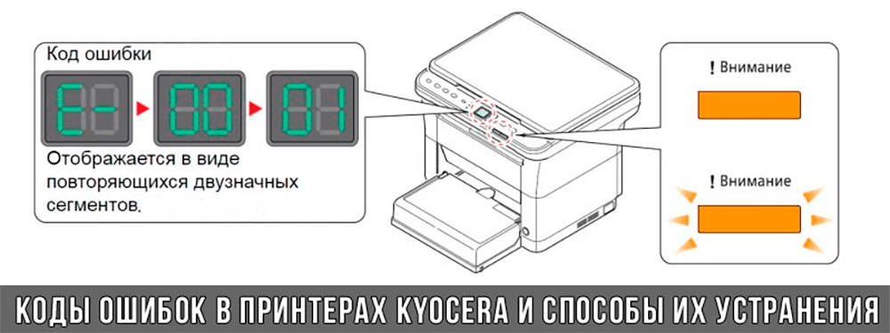
К счастью, оргтехника Kyocera оснащена системой самодиагностики (так же, как и струйные принтеры Canon). Поэтому, в случае возникновения проблемы, устройство самостоятельно выявит уязвимое место и сообщит Вам об этом миганием соответствующего индикатора на панели управления либо кодом ошибки, выведенным на дисплей принтера.
Если Вы не являетесь мастером по обслуживанию принтеров и МФУ Kyocera, то, чтобы понять, о чем сообщает печатающее устройство, Вам потребуется расшифровать указанный им код. Для этого мы добавили в статью таблицу кодов ошибок лазерных принтеров Kyocera серии FS и не только.
Коды ошибок принтеров и МФУ Kyocera, которые можно исправить самостоятельно
|
Код ошибки |
Значение ошибки |
Решение проблемы |
|
E-0001 (E1) |
Поврежден чип картриджа либо установлен неоригинальный картридж. |
Замените установленный картридж оригинальной версией изделия. Если хотите сэкономить, тогда купите и установите новый чип на картридж или перепрошейте принтер Kyocera. Однако предварительно не помешает попробовать сбросить ошибку соответствующей комбинацией клавиш (как это сделать, читайте в статье «Сброс ошибки установки неоригинального картриджа в принтерах Kyocera»). |
|
E-0002 (E2) |
Регион использования картриджа и принтера не совпадают. |
Замените чип или прошейте принтер Kyocera. |
|
E-0003 (E3) |
Заполнена память принтера или МФУ Kyocera. |
Отпечатайте ранее отсканированные листы или очистите очередь печати нажатием кнопки Стоп/Сброс (ранее отсканированные листы также удалятся из памяти принтера, даже если они еще не были распечатаны). |
|
E-0007 (E7) |
Тонер-картридж Kyocera израсходовал ресурс красящего вещества. |
Замените или заправьте картридж Kyocera (если используете совместимый или перезаправленный расходник, то после установки его в принтер не забудьте сбросить ошибку зажатием на 3-5 секунды кнопок [Ок] и [Сброс/Стоп]). |
|
E-0008 (E8) |
Открыта крышка принтера либо не работает датчик закрытия крышек устройства. |
Откройте и еще раз закройте переднюю и заднюю крышку принтера. Во время закрытия Вы должны услышать характерный щелчок. Если не помогло, то причина в неисправности датчика. |
|
E-0009 (E9) |
Лоток приема бумаги полон. |
Уберите все отпечатанные листы бумаги из выходящего лотка. Чтобы возобновить печать, нажмите кнопку [Старт]. |
|
E-0012 (E12) |
Ошибка памяти принтера Kyocera. |
Попробуйте уменьшить разрешение печати. Скорее всего, формат создаваемого отпечатка не соответствует возможностям принтера. |
|
E-0014 (E14) |
Установлен неверный формат бумаги (неподдерживаемый принтером Kyocera). |
Поменяйте бумагу на поддерживаемую принтером либо смените ее формат в настройках печати. Попробуйте обновить программное обеспечение. Возможно, это расширит поддерживаемые принтером Kyocera форматы. |
|
E-0015 (E15) |
Устройство не подключено к электрической сети либо на компьютере нет (не работает) драйвера принтера Kyocera. |
Проверьте подключение печатающего аппарата к электрической сети, а также целостность кабеля. Если ошибка не исчезает, скачайте драйвер принтера Kyocera и установите его на компьютер. |
|
E-0017 (E17) |
Ошибка передачи данных. |
Проверьте подключение принтера к компьютеру. Кабель не должен быть длиннее 5 метров, а также обязан поддерживать стандарт USB 2.0. Кроме того, переустановите драйвер принтера и утилиту Kyocera Client Tool. |
|
E-0018 (E18) |
Очередь печати заполнена. |
Очистите очередь печати нажатием кнопки [Сброс] либо через драйвер принтера. |
|
E-0019 (E19) |
Неверный формат печати. |
Отмените печать нажатием кнопки [Стоп/Сброс]. Выберите в настройках принтера соответствующий режим печати, а также установите в лоток поддерживаемый принтером формат бумаги. |
|
J-0000 (jam0000) |
Замятие бумаги за задней крышкой. |
Откройте крышку и извлеките бумагу. Проверьте надежность крепления бумаги в лотке, а также принтер на наличие посторонних предметов. Еще причина может быть в пружине выходного флажка. Если она растянулась, то может плохо работать фиксатор. Также проблема может быть из-за печки, сделайте ее ревизию, переборку и смазку. |
|
J-0501 (jam0501) |
Бумага застряла в принтере Kyocera |
Извлеките замятую бумагу. Проверьте надежность установки бумаги во входной лоток. Проверьте целостность роликов протяжки бумаги, а также принтер на наличие посторонних предметов. Если не помогло, стоит внимательно осмотреть ребра на направляющей пластине. На них могут образоваться сколы, трещины и заусенцы. Их можно слегка подчистить наждачной бумагой (нулевкой). |
|
J-0511 (jam0511) |
Принтер Kyocera замял бумагу. |
Извлеките замятую бумагу и повторите печать. Если проблема не исчезла, несите принтер в сервис. Скорее всего, изношен ролик протяжки бумаги. |
|
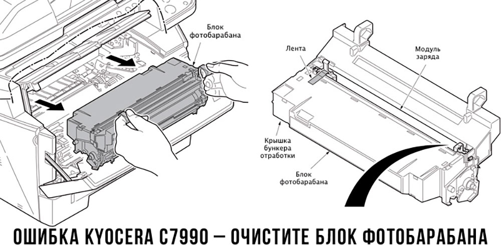
C7990 |
Бункер драм-картриджа (блока фотобарабана) заполнен отработанным тонером либо неисправен счетчик отработки красящего вещества. Еще проблема может быть в главной плате PWB. |
Осуществите чистку драм-картриджа (блока фотобарабана). Если проблема в датчике или плате, то нужно отнести принтер в СЦ на диагностику. |
|
F248 |
Ошибка обработки отпечатываемого материала. |
Перезагрузите принтер. Уберите неподдерживаемые спецсимволы из отпечатка. Обновите ПО принтера Kyocera. Смените режим работы принтера с PDL на GDI (Пуск -> Принтеры -> Свойства -> Параметры устройства). |
|
PF |
Отсутствует бумага в лотке подачи. |
Загрузите листы бумаги во входной лоток. Если принтер по-прежнему не печатает, значит нужно искать проблему в чем-то другом. |
|
1101 |
Ошибка сканирования через сеть из-за неправильного имени SMTP сервера. |
Пропишите DNS-адреса помимо прочих настроек печати по сети. |
|
1102 |
Некорректная настройка сканера для работы через сеть |
Зайдите в Web-панель управления принтером (нужно в адресную строку браузера ввести iP принтера Kyocera). Далее в зависимости от модели введите логин и пароль (Admin/Admin или просто admin00 без логина). Далее следуйте инструкции:
Логин и пароль нужны обязательно, если их нет, то следует создать. |
|
2101 |
Ошибка передачи данных при сканировании через сеть. |
Правильно настройте параметры (как для ошибки 1102), только предварительно отключите на ПК антивирус и брандмауэр. |
Если Вы испытали все способы, но не смогли убрать ошибку, то следует нести печатающее устройство в сервисный центр. Кроме того, есть ряд ошибок (высвечиваемых на дисплее принтера), которые нельзя устранить в домашних условиях. Соответствующие коды ошибок принтеров Kyocera представляем в очередной таблице.
Коды ошибок принтеров и МФУ Kyocera, которые нужно устранять в сервисном центре
|
Код ошибки |
Значение ошибки |
Решение проблемы |
|
0030 |
Неисправность платы управления факсом принтера. |
Замена платы. |
|
0100 |
Неисправность платы управления или флеш-памяти принтера. |
Замена платы. |
|
0120 |
Ошибка чтения mac-адреса из-за неисправности флеш-памяти принтера. |
Замена платы. |
|
0190 |
Неисправность платы управления или флеш-памяти принтера. |
Замена платы. |
|
0630 |
Неисправность платы управления принтера. |
Замена платы. |
|
1020 |
Неисправность мотора, привода или отсутствие контакта. |
Разборка принтера и замена изношенных частей. Проверка надежности подключений, замена разорванных (прогоревших) кабелей. Ремонт или замена привода мотора. |
|
1040 |
Неисправность мотора, привода или отсутствие контакта. |
Разборка принтера и замена изношенных частей. Проверка надежности подключений, замена разорванных (прогоревших) кабелей. Ремонт или замена привода мотора. |
|
2000 |
Неисправность главной платы управления, соединительного кабеля или привода принтера. |
Проверить ремни, шестерни и ролики привода. Смазать или заменить, если есть дефекты. Заменить привод или главную плату. |
|
3100 (C3100) |
Неисправность главной платы, привода сканера, датчика положения или нарушение целостности соединений. |
Проверить наличие разрывов и отсутствия контакта. Смазать или заменить изношенные элементы привода. Заменить привод, главную плату, датчик или соединительный кабель. Если Вам повезло, то возможно забыли отключить фиксатор блока сканера. |
|
3101 |
Сетевой кабель не подсоединен, или нарушена работа концентратора. Еще может быть из-за наличия вирусов в системе или неправильно заданным параметрам сервера SMTP. |
Проверить соединения, правильно настроить параметры сети. |
|
3300 |
Неисправность главной платы, датчика CIS или соединительного кабеля. |
Проверить контакты, заменить плату или датчик. |
|
3500 |
Неисправность главной платы или нарушение соединения контактов. |
Проверить контакты, заменить плату. |
|
4000 (C4000) |
Неисправность главной платы, привода сканера или нарушение соединений. Однако чаще всего ошибка лазера. |
Проверить контакты, заменить плату или привод блока сканера. Почистить лазер, смазать ось полигон-мотора, либо полностью заменить блок лазера. |
|
4200 |
Неисправность главной платы, блока сканера или датчика BD. |
Отключить питание принтера на 30 минут. Если не помогло, то следует заменить привод сканера или главную плату принтера. |
|
6000 (С6000) |
Неисправность главной платы, термостата, печки или нарушение соединения контактов. |
Проверить и поправить контакты. Заменить фьюзер. Ремонт или замена печки, термодатчика, термопредохранителя и т.д. |
|
6020 |
Сгорание термистора или главной платы. |
Замена термистора или главной платы. |
|
6030 |
Неисправность главной платы, термостата или термистора. Возможно, причина в отсутствии контакта. |
Проверить соединения. Заменить плату, термостат или термистор. |
|
6400 |
Неисправность главной платы, отсутствие питания или контакта. |
Заменить плату или источник питания. |
|
F000 |
Неисправность главной платы или отсутствие контакта. |
Проверить соединение ремня безопасности. Заменить ремень или плату управления. |
|
F020 |
Неисправность элементов памяти принтера. |
Перезагрузить принтер. Если ошибка не устранилась – заменить плату управления. |
|
F040 |
Неисправность главной платы принтера. |
Перезагрузить принтер. Если ошибка не устранилась – заменить плату управления. |
|
F05D |
Неисправность главной платы. Сбой программного оборудования привода. Проблемы с прошивкой принтера Kyocera. |
Перезагрузить принтер. Если ошибка не устранилась – заменить плату управления. Перепрошить принтер Kyocera. |
|
F245 F246 F247 F375 |
Принтер Kyocera заблокирован из-за проблемы, вызванной отказом источника питания. |
Нужно перепрошить принтер специальной сервисной микропрограммой. |
Обратите внимание: Если у печатающего устройства нет дисплея, то определить проблему можно по светодиодным индикаторам, встроенным в панель управления принтером. Например, у Kyocera Ecosys P2135D нужно сосчитать количество миганий индикаторов красного цвета и таким образом определить число, указывающее на ту или иную ошибку. В свою очередь, у модели Kyocera FS-1040 все зависит от темпа мигания светодиода с надписью «Внимание!» («Attention!»):
- Мигает медленно – указывает на отсутствие бумаги в лотке или тонера в картридже.
- Мигает быстро – оповещает о проблеме с памятью устройства, переполненном лотке или замятии бумаги, а также об использовании неоригинальных расходных материалов.
- Горит постоянно – говорит о проблемах с картриджем или фотобарабаном либо указывает на открытые крышки принтера.
Чтобы потребитель мог наверняка определить проблему, рекомендуем использовать утилиту Kyocera Client Tool, которая идет в комплекте с драйверами принтера.
Ваше Имя:
Ваш вопрос:
Внимание: HTML не поддерживается! Используйте обычный текст.
Оценка:
Плохо
Хорошо
Введите код, указанный на картинке:


- Code: 0030
- Description: FAX PWB system error The FAX process cannot be continued due to the malfunction of the FAX PWB.
- Remedy: FAX PWB Replace the FAX PWB
- Code: 0070
- Description: FAX PWB incompatible detection error In the initial communication with the FAX PWB,
- Remedy: FAX PWB Replace the FAX PWB. Main/Engine PWB Replace the main/engine PWB.
- Code: 0100
- Description: Backup memory device error Outputs an abnormal status from the flash memory.
- Remedy: Flash memory Replace the main/engine PWB. Main/Engine PWB Replace the main/engine PWB.
- Code: 0120
- Description: MAC address data error In case MAC address is invalid data
- Remedy: Flash memory Replace the main/engine PWB.
- Code: 0130
- Description: Backup memory Read/write error Read/write to the NAND memory cannot be executed.
- Remedy: Flash memory Replace the main/engine PWB. Main/Engine PWB Replace the main/engine PWB.
- Code: 0140
- Description: Backup memory data error At power up, the data that was read from the NAND memory has been determined to be a error.
- Remedy: Flash memory Replace the main/engine PWB.
Main/Engine PWB Replace the main/engine PWB.
- Code: 0150
- Description: EEPROM read/write error (Main/ Engine PWB) Mismatch of reading data from two locations occurs 8 times successively. Mismatch between writing data and reading data occurs 8 times successively.
- Remedy: EEPROM(YS1) Confirm that the EEPROM has been properly installed and repair if failed.
Main/Engine PWB Replace the main/engine PWB.
EEPROM(YS1) Contact the service support.
- Code: 0160
- Description: Backup memory data error Illegal data is detected in the EEPROM Counter data checksum does not match in all buffers
- Remedy: EEPROM(YS1) Check that the EEPROM (YS1) is firmly installed and repair it if failed. Main/Engine PWB Replace the main/engine PWB. EEPROM(YS1) Contact the service support.
- Code: 0170
- Description: Billing counting error Checksum error was detected both in the billing counter and IPU backup memory
- Remedy: Main/Engine PWB Replace the main/engine PWB.
EEPROM(YS1) Contact the service support.
- Code: 0180
- Description: Machine number mismatch When the power is turned on, the machine number does not match between the main and engine side.
- Remedy: Main/Engine PWB Execute U004 machine number setting
EEPROM(YS1) Contact the service support.
- Code: 0190
- Description: Backup memory device error Unable to read out data from the EEPROM. The above remains at 3 times of retries
- Remedy: Main/Engine PWB Replace the main/engine PWB.
EEPROM(YS1) Contact the service support.
- Code: 0500
- Description: Drive lock detection by engine firmware The main motor was left rotating when monitoring it in the regular interval (monitored also during the maintenance mode)
- Remedy: Main/Engine PWB Turn the power switch off and on If not corrected, replace the main/ engine PWB.
- Code: 0510
- Description: High voltage remote control error detection It was detected that the high voltage remote signal (synchronized with the feed motor remote) is on while the drum is not driven
- Remedy: Main/Engine PWB Turn the power switch off and on If not corrected, replace the main/ engine PWB.
- Code: 0530
- Description: Backup task error detection The time for the backup task not being in operation is 30s or more
- Remedy: Main/Engine PWB Turn the power switch off and on If not corrected, replace the main/ engine PWB.
- Code: 0540
- Description: Unexpected engine firmware control detection? (Preventing the solenoid from continuously being on) The solenoid was continuously on for the specified time or more
- Remedy: Main/Engine PWB Turn the power switch off and on If not corrected, replace the main/ engine PWB.
- Code: 0800
- Description: Print sequence error The printing sequence jam (JAM010X) occurred twice consecutively.
- Remedy: Main/Engine PWB Turn the power switch off and on If not corrected, replace the main/ engine PWB.
- Code: 0830
- Description: FAX PWB flash program area checksum error The program stored in the flash memory on the FAX PWB is broken and cannot be executed.
- Remedy: FAX PWB Replace the FAX PWB.
- Code: 0840
- Description: RTC error Communication with the RTC has failed The RTC data mismatch such as dead battery
- Remedy: Battery on the main/engine PWB Check it and repair it if it is faulty.
Main/Engine PWB Replace the main/engine PWB.
- Code: 0870
- Description: FAX PWB large data transmission error DMA transmission failed between the main/engine PWB and FAX PWB
- Remedy: FAX PWB Reattach the FAX PWB.
FAX PWB or main/engine PWB Replace the FAX PWB or main/engine PWB.
- Code: 0920
- Description: Fax file system error The backup data is not retained for file system abnormality of the flash memory of the FAX PWB.
- Remedy: FAX PWB Replace the FAX PWB.
- Code: 0970
- Description: 24V power down detect The power shutoff was detected by the controller
- Remedy: Interlock switch Check that the interlock switch is turned on properly by the front cove.
Low voltage power supply PWB Check if there is defective connection in the connector of the low voltage power supply PWB, and then check the 24V output from the main/engine PWB (YC20-1, 2,3). If not, replace the low voltage power supply PWB.
Main/Engine PWB Replace the main/engine PWB and check the operation.
- Code: 1810
- Description: Communication error with the paper feeder (1st PF) No paper feeder was detected after the paper feeder connection was detected at power-up
- Remedy: Paper feeder Check the wiring connection status with the main unit, and if necessary, reconnect it.
PF main PWB 1. Confirm that the wiring connector is firmly connected, and if necessary, connect the connector all the way in. PF main PWB — Main/engine PWB (YC17) 2. If the wiring is disconnected, shortcircuited or has a ground fault, replace the wire. 3. Replace the PF main PWB.
Main/ Engine PWB 1. Check the engine firmware and upgrade to the latest version if necessary. 2. Replace the main/engine PWB.
- Code: 1820
- Description: Communication error with the paper feeder (2nd PF) No paper feeder was detected after the paper feeder connection was detected at power-up
- Remedy: Paper feeder Check the wiring connection status with the main unit, and if necessary, reconnect it.
PF main PWB 1. Confirm that the wiring connector is firmly connected, and if necessary, connect the connector all the way in. PF main PWB and Main/engine PWB (YC47) 2. If the wiring is disconnected, shortcircuited or has a ground fault, replace the wire. 3. Replace the PF main PWB.
Main/ Engine PWB 1. Check the engine firmware and upgrade to the latest version if necessary. 2. Replace the main/engine PWB.
- Code: 2000
- Description: Main motor steady-state error After the main motor was stabilized, the ready signal was not detected for consecutive 1s.
- Remedy: Wire and connector between the main motor and main/engine PWB (YC9) If the connector is not inserted enough, reinsert it. Or check the wire’s continuity and replace the wire if there is no continuity.
Main motor drive transmission system Check if each roller and gear rotate smoothly. Apply grease to the bushings and gears if they are faulty. Check each gear if it is damaged and replace it if there is damage.
Main motor Replace the main motor.
Main/Engine PWB Replace the main/engine PWB.
- Code: 2010
- Description: Main motor start-up error The ready signal was not detected when passing 2s after the main motor is started up.
- Remedy: Wire and connector between the main motor and main/engine PWB (YC9) If the connector is not inserted enough, reinsert it. Or check the wire’s continuity and replace the wire if there is no continuity.
Main motor drive transmission system Check if each roller and gear rotate smoothly. Apply grease to the bushings and gears if they are faulty. Check each gear if it is damaged and replace it if there is damage.
Main motor Replace the main motor.
Main/Engine PWB Replace the main/engine PWB.
- Code: 2600
- Description: PF conveying motor error (Paper feeder) The ready signal is not detected within 2s after the PF conveying motor of the cassette 2 turns on.
- Remedy: Connection of the wire and connector PF conveying motor — PF main PWB If the connector is not inserted enough, reinsert it. Or check the wire’s continuity and replace the wire if there is no continuity.
PF conveying motor drive transmission system Check if each roller and gear rotate smoothly. Apply grease to the bushings and gears if they are faulty. Check each gear if it is damaged and replace it if there is damage.
PF conveying motor Replace the PF conveying motor.
- Code: 2610
- Description: PF conveying motor error (Paper feeder) The ready signal is not detected within 2s after the PF conveying motor of the cassette 3 turns on.
- Remedy: Connection of the wire and connector PF conveying motor — PF main PWB If the connector is not inserted enough, reinsert it. Or check the wire’s continuity and replace the wire if there is no continuity.
PF conveying motor drive transmission system Check if each roller and gear rotate smoothly. Apply grease to the bushings and gears if they are faulty. Check each gear if it is damaged and replace it if there is damage.
PF conveying motor Replace the PF conveying motor.
- Code: 3100
- Description: Carriage error 1) While the HP sensor is interrupted at the initial drive, it is not released when driven by 66.1mm toward the scanning direction 2) During the initial drive while the HP sensor is released, the HP sensor is not interrupted when driving it by 379.5mm toward the return direction
- Remedy: Scanner motor 1. Move the scanner manually to check if there is too much load. 2. Check that the scanner drive belt is not disengaged. 3. Confirm that the wiring connector is firmly connected, and if necessary, connect the connector all the way in. Scanner motor — Main/engine PWB (YC31) 4. If the wiring is disconnected, shortcircuited or has a ground fault, replace the wire. 5. Replace the scanner motor.
Home position sensor 1. Check that the sensor is correctly positioned. 2. Confirm that the wiring connector is firmly connected, Insert the connector all the way in. Home position sensor — Main/engine PWB (YC17) 3. Replace the home position sensor.
CIS Replace the scanner carriage and execute U411.
Main/ Engine PWB Replace the main/engine PWB.
- Code: 3200
- Description: CIS lamp error The white reference data obtained when the lamp is turned on at the time of initialization is lower than the rated value.
- Remedy: CIS Replace the scanner carriage and execute U411.
Main/ Engine PWB Replace the main/engine PWB.
- Code: 3210
- Description: DP CIS lamp error The white reference data obtained when the lamp is turned on at the time of initialization is lower than the rated value. (40 ppm model only)
- Remedy: DP CIS 1. Confirm that the wiring connector is firmly connected, and if necessary, connect the connector all the way in. DPCIS — Main/Engine PWB(YC509) 2. Replace DPCIS and execute U411.
- Code: 3300
- Description: CIS AGC error An error was detected when processing the front side AGC
- Remedy: CIS 1. Confirm that the wiring connector is firmly connected, and if necessary, connect the connector all the way in. CIS — Main/Engine PWB (YC506) 2. If the wiring is disconnected, shortcircuited or has a ground fault, replace the wire. 3. Replace the scanner carriage and execute U411
Main/Engine PWB Replace the main/engine PWB.
- Code: 3310
- Description: DP CIS AGC error An error was detected when processing the back side AGC (40 ppm model only)
- Remedy: DP CIS 1. Confirm that the wiring connector is firmly connected, and if necessary, connect the connector all the way in. DPCIS — Main/Engine PWB(YC509) 2. Replace DPCIS and execute U411.
Main/Engine PWB Replace the main/engine PWB.
- Code: 3500
- Description: Scanner — ASIC communication error A communication error is detected during communication. (Read-back values are different.)
- Remedy: CIS 1. Confirm that the wiring connector is firmly connected, and if necessary, connect the connector all the way in. CIS — Main/Engine PWB (YC506) 2. If the wiring is disconnected, shortcircuited or has a ground fault, replace the wire. 3. Replace the image scanner carriage and execute U411.
Main/Engine PWB Replace the main/engine PWB.
- Code: 4000
- Description: Polygon motor initial error (LSU) The polygon motor ready signal is not detected when passing 10s after starting up the polygon motor
- Remedy: Laser scanner unit (LSU) 1. Confirm that the wiring connector is firmly connected, and if necessary, connect the connector all the way in. Polygon motor — Main/engine PWB (YC3) If the wiring is disconnected, short-circuited or has a ground fault, replace the wire. 2. Replace the LSU.
Main/Engine PWB 1. Check the engine firmware and upgrade to the latest version if necessary. 2. Replace the main/engine PWB.
- Code: 4010
- Description: Polygon motor steady-state error (LSU) The polygon motor ready signal is not for consecutive 1s after the polygon motor is stabilized
- Remedy: Laser scanner unit (LSU) 1. Confirm that the wiring connector is firmly connected, and if necessary, connect the connector all the way in. Polygon motor — Main/engine PWB (YC3) If the wiring is disconnected, short-circuited or has a ground fault, replace the wire. 2. Replace the LSU.
Main/Engine PWB 1. Check the engine firmware and upgrade to the latest version if necessary. 2. Replace the main/engine PWB.
- Code: 4201
- Description: BD steady-state error (LSU) BD was not obtained during the steady rotation
- Remedy: Laser scanner unit (LSU) 1. Confirm that the wiring connector is firmly connected, and if necessary, connect the connector all the way in. LSU — Main/Engine PWB (YC505) 2. If the wiring is disconnected, shortcircuited or has a ground fault, replace the wire. 3. Replace the LSU.
Main/Engine PWB Replace the main/engine PWB.
- Code: 6000
- Description: Broken fuser heater wire (main) During warm-up, the temperature detected by the thermopile does not reach 100°C/212 °F when turning the heater on for consecutive 10s During warm up, the temperature detected by the thermopile does not reach the ready temperature when passing 30s after reaching 60°C/ 212°F.
- Remedy: Fuser unit 1. Make sure there is no paper jam. 2. Confirm that the wiring connector is firmly connected, and if necessary, connect the connector all the way in. Fuser unit — Main/Engine PWB(YC19) 3. If the wiring is disconnected, shortcircuited or has a ground fault, replace the wire. 4. If the fuser heater is not turned on (broken thermostat wire), replace the fuser unit.
Low voltage power supply PWB 1. Confirm that the wiring connector is firmly connected, and if necessary, connect the connector all the way in. Heater — Low voltage power supply PWB (YC102) Low voltage power supply PWB — Main/ Engine PWB(YC20) 2. Replace the low voltage power supply PWB.
Main/Engine PWB Replace the main/engine PWB.
- Code: 6020
- Description: Fuser thermopile high temperature error (main) During drive, the thermopile detected 200C/392 °F for 5s The temperature detected by the thermopile rose 18C/65 °F or more when passing 1s or more after the drive is stopped Detected temperature at that time is 200C/392 °or more
- Remedy: Thermopile 1. Reconnect the wire connector Replace the wire if there is no continuity. Thermopile — Main/engine PWB (YC2) 2. Check how the thermopile is attached. If not attached to the holder, correct it 3. Replace the thermopile if not repaired
Fuser unit 1. Make sure there is no paper jam. 2. If the fuser heater is not turned on (broken thermostat wire), replace the fuser unit.
Low voltage power supply PWB 1. Confirm that the wiring connector is firmly connected, and if necessary, connect the connector all the way in. Low voltage power supply PWB — Main/ Engine PWB(YC20) 2. Replace the low voltage power supply PWB.
Main/Engine PWB Replace the main/engine PWB.
- Code: 6030
- Description: Broken fuser thermopile wire (main) The thermopile detected an abnormal value
- Remedy: Thermopile 1. Reconnect the wire connector Replace the wire if there is no continuity. Thermopile — Main/engine PWB (YC2) 2. Replace the thermopile if not repaired
Main/Engine PWB Replace the main/engine PWB.
- Code: 6050
- Description: Fuser thermopile low temperature error (main) During printing, the temperature detected by the thermopile is less than 100C/212°F for consecutive 3s
- Remedy: Power supply voltage 1. Check no voltage drop exceeding 10% of the rated during printing. 2. If the power is overloaded, change the AC outlet that supplies power.
Thermopile 1. Reconnect the wire connector Replace the wire if there is no continuity. Thermopile — Main/engine PWB (YC2) 2. Check how the thermopile is attached. If not attached to the holder, correct it 3. Replace the thermopile if not repaired
Fuser unit 1. Make sure there is no paper jam. 2. Confirm that the wiring connector is firmly connected, and if necessary, connect the connector all the way in. Fuser unit — Main/Engine PWB(YC19) 3. If the wiring is disconnected, shortcircuited or has a ground fault, replace the wire. 4. If the fuser heater is not turned on (broken thermostat wire), replace the fuser unit.
Low voltage power supply PWB 1. Confirm that the wiring connector is firmly connected, and if necessary, connect the connector all the way in. Heater — Low voltage power supply PWB (YC102) Low voltage power supply PWB — Main/ Engine PWB(YC20) 2. Replace the low voltage power supply PWB.
Main/Engine PWB Replace the main/engine PWB.
- Code: 6200
- Description: Fuser heater error (sub) During warm-up, the temperature detected by the thermistor does not reach 60C/212.0 °F when turning the heater on for consecutive 30s. During warm-up, the temperature detected by the thermistor does not reach the ready temperature when passing 20s after it reaches 60C/ 212°F.
- Remedy: Thermopile 1. Reconnect the wire connector Replace the wire if there is no continuity. Thermopile — Main/engine PWB (YC2) 2. Replace the thermopile if not repaired
Fuser unit 1. Make sure there is no paper jam. 2. Confirm that the wiring connector is firmly connected, and if necessary, connect the connector all the way in. Fuser unit — Main/Engine PWB(YC19) 3. If the wiring is disconnected, shortcircuited or has a ground fault, replace the wire. 4. If the fuser heater is not turned on (broken thermostat wire), replace the fuser unit.
Low voltage power supply PWB 1. Confirm that the wiring connector is firmly connected, and if necessary, connect the connector all the way in. Heater — Low voltage power supply PWB (YC102) Low voltage power supply PWB — Main/ Engine PWB(YC20) 2. Replace the low voltage power supply PWB.
Main/Engine PWB Replace the main/engine PWB.
- Code: 6220
- Description: Fuser heater high temperature error (sub) The temperature detected by the thermopile is 240°C/464 °F while the drive is stopped The temperature detected by the thermopile is 255°C/491 °F during drive
- Remedy: Thermopile 1. Reconnect the wire connector Replace the wire if there is no continuity. Thermopile — Main/engine PWB (YC2) 2. Check how the thermopile is attached. If not attached to the holder, correct it 3. Replace the thermopile if not repaired
Fuser unit 1. Make sure there is no paper jam. 2. Confirm that the wiring connector is firmly connected, and if necessary, connect the connector all the way in. Fuser unit — Main/Engine PWB(YC19) 3. If the wiring is disconnected, shortcircuited or has a ground fault, replace the wire. 4. Replace the fuser unit.
Low voltage power supply PWB 1. Confirm that the wiring connector is firmly connected, and if necessary, connect the connector all the way in. Low voltage power supply PWB — Main/ Engine PWB(YC20) 2. Replace the low voltage power supply PWB.
Main/Engine PWB Replace the main/engine PWB.
- Code: 6230
- Description: Fuser thermistor wire break (sub) The thermistor’s AD value was abnormal
- Remedy: Fuser unit 1. Confirm that the wiring connector is firmly connected, and if necessary, connect the connector all the way in. Fuser unit — Main/Engine PWB(YC19) 2. If the wiring is disconnected, shortcircuited or has a ground fault, replace the wire. 3. If the fuser heater is not turned on (broken thermostat wire), replace the fuser unit.
Main/Engine PWB Replace the main/engine PWB.
- Code: 6250
- Description: Fuser heater low temperature error (sub) During printing, the temperature detected by the thermistor is less than 60°C/140°F for consecutive 3s
- Remedy: Thermopile 1. Reconnect the wire connector Replace the wire if there is no continuity. Thermopile — Main/engine PWB (YC2) 2. Check how the thermopile is attached. If not attached to the holder, correct it 3. Replace the thermopile if not repaired
Fuser unit 1. Make sure there is no paper jam. 2. Confirm that the wiring connector is firmly connected, and if necessary, connect the connector all the way in. Fuser unit — Main/Engine PWB(YC19) 3. If the wiring is disconnected, shortcircuited or has a ground fault, replace the wire. 4. Replace the fuser unit.
Low voltage power supply PWB 1. Confirm that the wiring connector is firmly connected, and if necessary, connect the connector all the way in. Heater — Low voltage power supply PWB (YC102) Low voltage power supply PWB — Main/ Engine PWB(YC20) 2. Replace the low voltage power supply PWB.
Main/Engine PWB Replace the main/engine PWB.
- Code: 6400
- Description: Zero-cross signal error During the heater turned on, the zero-cross signal disappears for consecutive 1s
- Remedy: Low voltage power supply PWB Replace the low voltage power supply PWB.
Main/Engine PWB Replace the main/engine PWB.
- Code: 6600
- Description: Fuser rotation error The fuser roller rotation detection is not input for consecutive 2s while the motor’s steady signal is input
- Remedy: Fuser unit 1. Make sure there is no paper jam. 2. Confirm that the wiring connector is firmly connected, and if necessary, connect the connector all the way in. Fuser unit — Main/Engine PWB(YC19) 3. If the wiring is disconnected, shortcircuited or has a ground fault, replace the wire. 4. Replace the fuser unit.
Main/Engine PWB Replace the main/engine PWB.
- Code: 6610
- Description: The fuser pressure release error The fuser pressure change is not complete within 10s after the instruction
- Remedy: Fuser unit 1. Make sure there is no paper jam. 2. Confirm that the wiring connector is firmly connected, and if necessary, connect the connector all the way in. Fuser unit — Main/engine PWB (YC19) 3. If the wiring is disconnected, shortcircuited or has a ground fault, replace the wire. 4. Replace the fuser unit.
Fuser pressure release error 1. Reverse-rotate the fuser gear manually to check if the fuser pressure can be released. 2. When releasing the pressure, check the fuser pressure release sensor is interrupted by the actuator Reattach it if the light is not interrupted 3. Reconnect the wire connector Replace the wire if there is no continuity. Fuser pressure release sensor — Main/ engine PWB (YC19) Fuser pressure release motor — Main/ engine PWB (YC1) 4. Replace the fuser pressure release motor.
Main/Engine PWB Replace the main/engine PWB.
- Code: 6650
- Description: Fuser thermopile EEPROM error 1. The thermopile EEPROM is not accessed 2. No response from the device at read was detected five time consecutively Data read at two points was unmatched eight times consecutively 3. Thermopile data checksum error
- Remedy: Thermopile 1. Reconnect the wire connector Replace the wire if there is no continuity. 2. Thermopile — Main/engine PWB (YC2) 3. Replace the thermopile if not repaired
Main/Engine PWB Replace the main/engine PWB.
- Code: 7220
- Description: Broken in-machine thermistor wire The sensor input sampling value is greater than the reference value.
- Remedy: In-machine temperature sensor 1. Confirm that the wiring connector is firmly connected, Insert the connector all the way in. In-machine temperature sensor — Main/engine PWB (YC1) 2. If the wiring is disconnected, shortcircuited or has a ground fault, replace the wire. Replace the in-machine temperature sensor PWB.
Main/Engine PWB Replace the main/engine PWB.
- Code: 7800
- Description: Broken outer thermistor wire The sensor input sampling value is abnormal. (After detecting an error, it is controlled at 23C/77 °F and 50%RH)
- Remedy: Temperature and humidity Sensor 1. Confirm that the wiring connector is firmly connected, and if necessary, connect the connector all the way in. Temperature and humidity sensor — Main/engine PWB (YC2) 2. If the wiring is disconnected, shortcircuited or has a ground fault, replace the wire. 3. Replace the Temperature and humidity sensor PWB.
Main/Engine PWB Replace the main/engine PWB.
- Code: 7990
- Description: Waste toner full The waste toner sensor detected the waste toner reservoir in the drum unit is full
- Remedy: Drum unit Turn the power switch off and on Replace the drum unit if not repaired.
Waste toner sensor Replace the waste toner sensor.
Main/Engine PWB Replace the main/engine PWB.
- Code: F000
- Description: Communication error between Main/Engine PWB — Operation panel PWB
- Remedy: Connection of the wires and connectors between the main/engine PWB — the operation panel PWB. If the connector is not inserted enough, reinsert it. Or check the wire’s continuity and replace the wire if there is no continuity.
Operation panel PWB Replace the operation panel PWB. (TSI: see page 4-138, LCD: see page 4- 141)
Main/Engine PWB Replace the main/engine PWB.
- Code: F010
- Description: Main/Engine PWB Checksum error
- Remedy: Main/Engine PWB Unplug the power cord from the wall outlet, and wait five seconds. Then plug in the power cord and then turn on the power switch. If not corrected, replace the main/ engine PWB.
- Code: F020
- Description: Main/engine PWB RAM checksum error
- Remedy: Main/engine PWB memory (RAM) Turn the power switch off and on If not corrected, replace the main/ engine PWB.
Expansion memory (DIMM) Replace the expansion memory (DIMM)
- Code: F040
- Description: Main/engine PWB engine communication error
- Remedy: Main/Engine PWB Turn the power switch off and on If not repaired, replace the EEPROM on the main/engine PWB or main/engine PWB.
- Code: F041
- Description: Main/engine PWB — Scanner PWB communication error
- Remedy: Main/Engine PWB Turn the power switch off and on If not corrected, replace the main/ engine PWB.
- Code: F050
- Description: Main/engine PWB engine checksum error
- Remedy: Main/Engine PWB Download the engine firmware again (TSI: see page 4-138,LCD: see page 4- 141)
Main/Engine PWB Turn the power switch off and on If not repaired, replace the EEPROM on the main/engine PWB or main/engine PWB.
- Code: F051
- Description: No scan engine main program
- Remedy: Main/Engine PWB Turn the power switch off and on If not corrected, replace the main/ engine PWB.
- Code: F12X
- Description: Abnormality detecting in a Scan control section
- Remedy: (1) Check the harness between Scan/DP<=>Main/Engine PWBs, and the connection state of a connector, and perform an operation check. (2) U021 Controller backup initialization is carried out and an operation check is performed. (3) Exchange a Scan/DP board and perform an operation check. (4) Exchange a Main/Engine PWB and perform an operation check. (5) Get USBLOG and contact service headquarters.
- Code: F14X
- Description: Abnormality detecting in a FAX control part
- Remedy: (1) Check the harness between FAX<=>Main/Engine PWBs, and the connection state of a connector, and perform an operation check. (2) U021 Controller backup initialization is carried out and an operation check is performed. (3) Perform a deed operation check for DIMM Clear by U671. * Notes(Since it disappears when received data remain, cautions are required.) (4) Exchange a FAX board and perform an operation check. (5) Exchange a Main/Engine PWB and perform an operation check. (6) Get USBLOG and contact service headquarters.
- Code: F15X
- Description: Abnormality detecting in an authentication device control section
- Remedy: (1) Check the harness between authentication device <=>Main/ Engine PWBs, and the connection situation of a connector, and perform an operation check. (2) Carry out U021 Main backup initialization and perform an operation check. (3) Exchange a Main/Engine PWB and perform an operation check. (4) Get USBLOG and contact service headquarters.
- Code: F18X
- Description: Abnormality detecting in a Video control section
- Remedy: (1) Check the harness between Engine<=>Main/Engine PWBs, and the connection state of a connector, and perform an operation check. (2) U021 Controller backup initialization is carried out and an operation check is performed. (3) Exchange a Main/Engine PWB and perform an operation check. (4) Get USBLOG and contact service headquarters.
- Code: F1DX
- Description: Abnormality detecting of the image memory Management Department
- Remedy: (1) Carry out U021 Main backup initialization and perform an operation check. (2) Exchange a Main/Engine PWB and perform an operation check. (3) Get USBLOG and contact service headquarters.
- Code: F21X, F22X, F23X
- Description: Abnormality detecting in an image-processing part
- Remedy: (1) Check contact of a DDR memory and perform an operation check. (2) Carry out U021 Main backup initialization and perform an operation check. (3) Exchange a Main/Engine PWB and perform an operation check. (4) Get USBLOG and contact service headquarters.
- Code: F24X
- Description: Abnormality detecting in the system Management Department
- Remedy: (1) Check contact of a DDR memory and perform an operation check. (2) Carry out U021 Main backup initialization and perform an operation check. (3) Exchange a Main/Engine PWB and perform an operation check. (4) Get USBLOG and contact service headquarters.
- Code: F25X
- Description: Abnormality detecting in a network management department
- Remedy: (1) Carry out U021 Main backup initialization and perform an operation check. (2) Exchange a Main/Engine PWB and perform an operation check. (3) Get USBLOG and packet capture and contact service headquarters.
- Code: F26X … F2AX
- Description: Abnormality detecting in the system Management Department
- Remedy: (1) Carry out U021 Main backup initialization and perform an operation check. (2) Exchange a Main/Engine PWB and perform an operation check. (3) Get USBLOG and contact service headquarters.
- Code: F2BX … F32X
- Description: Abnormality detecting in a network control part
- Remedy: (1) Carry out U021 Main backup initialization and perform an operation check. (2) Exchange a Main/Engine PWB and perform an operation check. (3) Get USBLOG and contact service headquarters.(Depending on an analysis result, it is packet capture acquisition)
- Code: F33X
- Description: Abnormality detecting in the Scan Management Department
- Remedy: (1) Check the harness between Scan/DP<=>Main/Engine PWBs, and the connection state of a connector, and perform an operation check. (2) U021 Controller backup initialization is carried out and an operation check is performed. (3) Exchange a Scan/DP board and perform an operation check. (4) Exchange a Main/Engine PWB and perform an operation check. (5) Get USBLOG and contact service headquarters.
- Code: F34X
- Description: Abnormality detecting in the Panel Management Department
- Remedy: (1) Check the harness between Panel<=>Main/Engine PWBs, and the connection state of a connector, and perform an operation check. * Notes (2) U021 Controller backup initialization is carried out and an operation check is performed. (3) Exchange a Panel board and perform an operation check. (4) Exchange a Main/Engine PWB and perform an operation check. (5) Get USBLOG and contact service headquarters.
- Code: F35X
- Description: Abnormality detecting in the printing controlling Management Department
- Remedy: (1) Carry out U021 Main backup initialization and perform an operation check. (2) Exchange a Main/Engine PWB and perform an operation check. (3) Get USBLOG and contact service headquarters.
- Code: F37X
- Description: Abnormality detecting in the FAX Management Department
- Remedy: (1) Carry out U021 Main backup initialization and perform an operation check. (2) Exchange a Main/Engine PWB and perform an operation check. (3) Get USBLOG and contact service headquarters.
- Code: F38X
- Description: Abnormality detecting in the authentication authorized Management Department
- Remedy: (1) Carry out U021 Main backup initialization and perform an operation check. (2) Exchange a Main/Engine PWB and perform an operation check. (3) Get USBLOG and contact service headquarters.
- Code: F3AX … F45X
- Description: Abnormality detecting in the Entity Management Department
- Remedy: (1) Carry out U021 Main backup initialization and perform an operation check. (2) Exchange a Main/Engine PWB and perform an operation check. (3) Get USBLOG and contact service headquarters.
- Code: F46X
- Description: Abnormality detecting of a printer rendering part
- Remedy: (1) Exchange a Main/Engine PWB and perform an operation check. (2) the acquisition wish of USBLOG — carry out (Depending on the (2) case, it is print capture data acquisition)
- Code: F47X, F48X, F49X
- Description: Abnormality detecting of an image editing processing part
- Remedy: (1) Carry out U021 Main backup initialization and perform an operation check. (2) Exchange a Main/Engine PWB and perform an operation check. (3) Get USBLOG and contact service headquarters.
- Code: F4DX, F4EX
- Description: Abnormality detecting in the Entity Management Department
- Remedy: (1) Carry out U021 Main backup initialization and perform an operation check. (2) Exchange a Main/Engine PWB and perform an operation check. (3) Get USBLOG and contact service headquarters.
- Code: F4FX
- Description: Abnormality detecting in the JOB Management Department
- Remedy: (1) Carry out U021 Main backup initialization and perform an operation check. (2) Exchange a Main/Engine PWB and perform an operation check. (3) Get USBLOG and contact service headquarters.
- Code: F50X
- Description: Abnormality detecting in the FAX Management Department
- Remedy: (1) Carry out U021 Main backup initialization and perform an operation check. (2) Exchange a Main/Engine PWB and perform an operation check. (3) Get USBLOG and contact service headquarters.
- Code: F51X … F57X
- Description: Abnormality detecting in a JOB execution part
- Remedy: (1) Carry out U021 Main backup initialization and perform an operation check. (2) Exchange a Main/Engine PWB and perform an operation check. (3) Get USBLOG and contact service headquarters.
- Code: F58X … F5EX
- Description: Abnormality detecting in the various-services Management Department
- Remedy: (1) Carry out U021 Main backup initialization and perform an operation check. (2) Exchange a Main/Engine PWB and perform an operation check. (3) Get USBLOG and contact service headquarters.
- Code: F5FX
- Description: Abnormality detecting in a service execution part
- Remedy: (1) Carry out U021 Main backup initialization and perform an operation check. (2) Exchange a Main/Engine PWB and perform an operation check. (3) Get USBLOG and contact service headquarters.
- Code: F62X
- Description: Abnormality detecting in a service execution part
- Remedy: (1) Carry out U021 Main backup initialization and perform an operation check. (2) Exchange a Main/Engine PWB and perform an operation check. (3) Get USBLOG and contact service headquarters.
- Code: F63X
- Description: Abnormality detecting in a device control section
- Remedy: (1) Carry out U021 Main backup initialization and perform an operation check. (2) Exchange a Main/Engine PWB and perform an operation check. (3) Get USBLOG and contact service headquarters.
- Code: F69X … F6CX
- Description: Abnormality detecting in a HyPAS-E part
- Remedy: (1) Carry out U021 Main backup initialization and perform an operation check. (2) Exchange a Main/Engine PWB and perform an operation check. (3) Get USBLOG and contact service headquarters.
-
Page 1: Service Manual
FS-1120D FS-1320D SERVICE MANUAL Published in June 2010 842LZ112 2LZSM062 Rev. 2…
- Page 2
CAUTION RISK OF EXPLOSION IF BATTERY IS REPLACED BY AN INCORRECT TYPE. DISPOSE OF USED BATTERIES ACCORDING TO THE INSTRUCTIONS. It may be illegal to dispose of this battery into the municipal waste stream. Check with your local solid waste officials for details in your area for proper disposal. ATTENTION IL Y A UN RISQUE D’EXPLOSION SI LA BATTERIE EST REMPLACEE PAR UN MODELE DE TYPE INCORRECT. -
Page 3: Revision History
Revision history Revision Date Replaced pages Remarks March 4, 2010 1-1-2, 1-2-1 June 4, 2010 1-1-1, 1-3-1, 1-3-11, 1-3-12…
- Page 4
This page is intentionally left blank. -
Page 5: Safety Precautions
Safety precautions This booklet provides safety warnings and precautions for our service personnel to ensure the safety of their customers, their machines as well as themselves during maintenance activities. Service personnel are advised to read this booklet carefully to familiarize themselves with the warnings and precautions described here before engaging in maintenance activities.
- Page 6
Safety warnings and precautions Various symbols are used to protect our service personnel and customers from physical danger and to prevent damage to their property. These symbols are described below: DANGER: High risk of serious bodily injury or death may result from insufficient attention to or incorrect compliance with warning messages using this symbol. -
Page 7: Installation Precautions
1. Installation Precautions WARNING • Do not use a power supply with a voltage other than that specified. Avoid multiple connections to one outlet: they may cause fire or electric shock. When using an extension cable, always check that it is adequate for the rated current…………………. •…
-
Page 8: Specifications 1
2. Precautions for Maintenance WARNING • Always remove the power plug from the wall outlet before starting machine disassembly….• Always follow the procedures for maintenance described in the service manual and other related brochures……………………….• Under no circumstances attempt to bypass or disable safety features including safety mechanisms and protective circuits.
- Page 9
• Do not remove the ozone filter, if any, from the copier except for routine replacement……. • Do not pull on the AC power cord or connector wires on high-voltage components when removing them; always hold the plug itself………………….•… - Page 10
This page is intentionally left blank. -
Page 11: Table Of Contents
(1) Precautions ……………………….1-5-1 (2) Drum…………………………1-5-1 (3) Toner container ……………………..1-5-1 (4) How to tell a genuine Kyocera Mita toner container…………….1-5-2 1-5-2 Outer covers ……………………….1-5-3 (1) Detaching and refitting the top cover………………..1-5-3 (2) Detaching and refitting the right and left covers …………….1-5-4 1-5-3 Paper feed section ……………………..1-5-6…
- Page 12
2LY/2LZ 1-5-6 Transfer/separation section ……………………1-5-14 (1) Detaching and refitting the transfer roller ………………1-5-14 1-5-7 Fuser section ……………………….1-5-16 (1) Detaching and refitting the fuser unit………………..1-5-16 (2) Switching the fuser pressure ………………….1-5-18 1-5-8 PWBs …………………………1-5-19 (1) Detaching and refitting the control PWB ………………1-5-19 (2) Detaching and refitting the power source PWB…………….1-5-22 (3) Detaching and refitting the operation panel PWB …………….1-5-24 (4) Detaching and refitting the high voltage PWB……………..1-5-25… -
Page 13: Specifications
2LY/2LZ-2 1-1 Specifications 1-1-1 Specifications Type ……….Desktop Printing method……. Electrophotography, laser scan Paper weight……..Cassette: 60 to 120 g/m (Duplex: 60 to 105 g/m MP tray: 60 to 220 g/m Paper type ……..Cassette: Plain, Preprinted, Bond, Recycled, Rough, Letterhead, Color (Colour), Prepunched, High quality, Custom 1 to 8 MP tray: Plain, Transparency, Preprinted, Labels, Bond, Recycled, Rough, Vellum,…
- Page 14
2LY/2LZ-1 ° ° Operating environment ….Temperature: 10 to 32.5 C/50 to 90.5 Humidity: 15 to 80% Altitude: 2,500 m/8,202 ft maximum Brightness: 1,500 lux maximum Controller ……..PowerPC 405F5/360 MHz Supported OS ……… Microsoft Windows 2000/XP/Vista/7, Windows Server 2003/2008, Mac OS X 10.x Interface………. -
Page 15: Parts Names
2LY/2LZ 1-1-2 Parts names (1) Overall Figure 1-1-1 Top cover MP tray Paper stopper Sub tray Top tray 10. Optional interface slot cover Operation panel 11. USB interface connector Right side cover 12. Rear cover Cassette 13. Power cord connector Front cover 14.
- Page 16
2LY/2LZ (2) Operation panel Figure 1-1-2 Ready indicator Attention indicator Toner indicator Data indicator Paper indicator Jam indicator Cancel key GO key 1-1-4… -
Page 17: Machine Cross Section
2LY/2LZ 1-1-3 Machine cross section Light path Paper path Paper path (option) Figure 1-1-3 Cassette Laser scanner unit MP tray Transfer/separation section Paper feed/conveying section 10. Fuser section Toner container 11. Exit section Developing unit 12. Top tray Main charger unit 13.
- Page 18
2LY/2LZ This page is intentionally left blank. 1-1-6… -
Page 19: Installation Environment
2LY/2LZ-1 1-2 Installation 1-2-1 Installation environment ° ° Temperature: 10 to 32.5 C/50 to 90.5 Humidity: 15 to 80%RH Power supply: 120 V AC, 8.0 A 220 — 240 V AC, 4.2 A ± ± Power source frequency: 50 Hz 0.3%/60 Hz 0.3% Installation location…
-
Page 20: Unpacking
2LY/2LZ 1-2-2 Unpacking 220 — 240 V AC model 120 V AC model Figure 1-2-2 Printer 11. Power cord Outer case 12. Pad Bottom pad L 13. Plastic bag Bottom pad R 14. Installation guide Machine cover 15. Panel GFIS sheet Top pad L 16.
-
Page 21: Removing The Tapes
2LY/2LZ (1) Removing the tapes Procedure 1. Remove three tapes. Tape Tape Tape Figure 1-2-3 1-2-3…
-
Page 22: Installing The Expanded Memory (Option)
2LY/2LZ 1-2-3 Installing the expanded memory (option) Procedure 1. Turn off printer power switch. Caution: Do not insert or remove expanded memory while printer power is on. Doing so may cause damage to the printer and the expanded memory. 2. Remove the right side cover. 3.
-
Page 23: Installing The Memory Card (Option)
2LY/2LZ 1-2-4 Installing the memory card (option) Procedure 1. Turn off printer power switch. Caution: Do not insert or remove memory card while printer power is on. Doing so may cause damage to the printer and the memory card. 2. Open the rear cover. Rear cover Figure 1-2-6 3.
-
Page 24: Installing The Network Interface Card (Option)
2LY/2LZ 1-2-5 Installing the network interface card (option) Procedure 1. Turn off printer power switch. Caution: Do not insert or remove network interface card while printer power is on. Doing so may cause damage to the printer and the network interface card. 2.
-
Page 25: Maintenance Mode
2LY/2LZ-2 1-3 Maintenance Mode 1-3-1 Maintenance mode The product incorporates several service modes which are activated by using the keys on the operation panel or by com- manding from a PC. (1) Executing a service mode Printing a status page for service purpose……..See page 1-3-2. Printing an event log (EVENT LOG) ……….
-
Page 26: Service Status Page
2LY/2LZ Service items Description Printing a status page Description for service purpose Prints a status page for service purpose. The status page includes various printing settings and service cumulative. Purpose To acquire the current printing environmental parameters and cumulative information. Procedure 1.
- Page 27
2LY/2LZ Service items Description Detail of service information Service information Total page 9690 [XXXXXXXX][XXXXXXXX][01/00] /t/U00/F00/N00 (6) (7) (8) /0020/0020/1061/0811/ (10) (11) (12) (13) /0000/0000/ /00/300/81/31/81/31/ (14)(15)(16)(17)(18)(19) (20) A:1234567890123456 (21) /02870284/03028003/83030286/86000086/02000000/02020202/02020202/ (22) /03030303/03030303/03030303/03030303/03000000/03030303/03030303/ SPD1:0203040508090A0B0C0D0F101112131415161718191A1B1C1D1E1F202122235E (23) (24) /00000000/00000000/00000000/00000000/00000000/00000000/00000000/00000000/00000000/00000000/00000000/ /00000000/00000000/00000000/00000000/00000000/00000000/00000000/00000000/00000000/00000000/00000000/ /00000000/00000000/00000000/00000000/00000000/00000000/00000000/00000000/00000000/00000000/00000000/ /00000000/00000000/00000000/00000000/00000000/00000000/00000000/00000000/00000000/00000000/00000000/ /00000000/00000000/00000000/00000000/00000000/00000000/00000000/00000000/00000000/00000000/00000000/ /00000000/00000000/00000000/00000000/00000000/00000000/00000000/00000000/00000000/00000000/00000000/ /00000000/00000000/00000000/00000000/00000000/00000000/00000000/00000000/00000000/00000000/00000000/ /00000000/00000000/00000000/00000000/00000000/00000000/00000000/00000000/00000000/00000000/00000000/… - Page 28
1 = 0: Overseas, 1: Domestic (Japan) [First byte/Second byte bit 2, 3 (Not used) (displayed in OEM model bit 4 = 0: Kyocera, 1: OEM only)] bit 5 = 0: For Europe, 1: For US bit 6 = 0: Non MICR mode, 1: MICR mode… - Page 29
2LY/2LZ Service items Description Items Description (20) Fixed asset number (Maximum 16 characters) (21) Paper type attributes Paper type setting value from 1 to 28 (fuser, weight, duplex) (unused paper type are always 0x00.) (22) Paper type attributes Paper type setting value from 1 to 28 (density) (unused paper type are always 0x00.) (23) Memory SPD information (slot… - Page 30
2LY/2LZ Service items Description Printing an event log Description (EVENT LOG) Prints a history list of occurrences of paper jam, self-diagnostics, toner replacements, etc. Purpose To allow machine malfunction analysis based on the frequency of paper misfeeds, self diag- nostic errors and replacements. Procedure 1. -
Page 31: Event Log
2LY/2LZ Service items Description EVENT LOG [EB20MA001/2LZ_1000.001.019] [40.00SFLB] [01] Firmware version: 2LZ_30000.001.024 Released: 20/January/2010 Printed page(s) 12345 Paper Jam Log Service Call Log Count. Event Count. Service Code 9993 10.48.01.08.01.01 11234 01.6000 10000 01.6000 9992 10.48.01.08.01.01 9999 01.6000 9991 10.48.01.08.01.01 9998 01.6000 9990…
- Page 32
[First byte/Second byte (dis- bit 2, 3 (Not used) played in OEM mode only)] bit 4 = 0: Kyocera, 1: OEM bit 5 = 0: For Europe, 1: For US bit 6 = 0: Non MICR mode, 1: MICR mode… - Page 33
2LY/2LZ Service items Description Items Description Paper Jam (a) Cause of paper jam cont. 10: Paper does not arrive at the registration sensor. (MP tray) [42] 10: Paper does not arrive at the registration sensor. (Cassette 1) [31] 10: Paper does not arrive at the registration sensor. (Cassette 2) [31] 10: Paper does not arrive at the registration sensor. - Page 34
2LY/2LZ Service items Description Items Description (c) Detail of paper source (Hexadecimal) Paper Jam Log cont. 00: MP tray 01: Cassette 1 (printer) 02: Cassette 2 (paper feeder 1) 03: Cassette 3 (paper feeder 2) 07: Duplex (d) Detail of paper size (Hexadecimal) 00: (Undefined) 09: B5R 20: Reply-paid postcard… - Page 35
2LY/2LZ-2 Service items Description Items Description (11) Unknown Toner Count. Item Remembers 1 to 5 of occur- The total page count at Unknown toner log code rence of unknown toner the time of the “Toner (1 byte, 2 categories) NOTE: detection. - Page 36
2LY/2LZ-2 Service items Description [REPLACE MAINTE- Description NANCE KIT] message [REPLACE MAINTENANCE KIT] message sheet is printed at the 1st power-up after the sheet page count exceeding 100,000 pages. Procedure Replace the maintenance kit. 30/32 ppm model (A4/Letter) Maintenance kit MK-162 (for 120 V specifications) Maintenance kit MK-160 (for 230 V specifications) Maintenance kit MK-164 (for 240 V specifications) 35/37 ppm model (A4/Letter) -
Page 37: Paper Misfeed Detection
2LY/2LZ 1-4 Troubleshooting 1-4-1 Paper misfeed detection (1) Paper misfeed indication If paper jams in the paper conveying system, or no paper sheets are fed at all, the printer automatically goes offline, and the jam indicator will flash rapidly. Status Monitor or COMMAND CENTER can indicate the location of the paper jam (the component where the paper jam has occurred).
-
Page 38: Paper Misfeed Detection Condition
2LY/2LZ (2) Paper misfeed detection condition Printer Peper feeder 1 (Option) (1) Registration sensor (2) Paper sensor (3) MP paper sensor (4) Paper exit sensor (5) PF paper sensor (6) PF paper feed sensor Peper feeder 2 (Option) Figure 1-4-2 1-4-2…
-
Page 39: Self-Diagnostic Function
2LY/2LZ 1-4-2 Self-diagnostic function (1) Self-diagnostic function The printer is equipped with self-diagnostic function which automatically halts the printer when an error is detected. The four indicators (Jam, Paper, Attention, Toner) are simultaneously lit, then indicate a specific error by the combination of the four indicators.
-
Page 40: Self Diagnostic Codes Indication
2LY/2LZ (2) Self diagnostic codes indication Sequence of display Indicates the occurrence of a self diagnostics error. 1.6 s 1.6 s 0.8 s 0.8 s Example of self-diagnostic code: 2610 (Refer to the following code conversion table) 0.8 s 0.8 s 0.8 s Indication example Lit (Green)
-
Page 41: Self Diagnostic Codes
2LY/2LZ (3) Self diagnostic codes Remarks Code Contents Causes Check procedures/corrective measures 0150 Control PWB EEPROM error Improper installation Check the installation of the EEPROM Detecting control PWB EEPROM control PWB EEPROM (U300) and remedy if necessary (See page (U300) communication error. (U300).
- Page 42
2LY/2LZ Remarks Code Contents Causes Check procedures/corrective measures 2610 PF paper feed motor error (Paper Defective harness Reinsert the connector. Also check for conti- feeder 1) between PF paper nuity within the connector harness. If none, The PF paper feed motor of paper feed motor and PF remedy or replace the harness (Refer to the feeder 1 ready input is not given for 2… - Page 43
2LY/2LZ Remarks Code Contents Causes Check procedures/corrective measures 6000 Broken fuser heater lamp wire Poor contact in the Reinsert the connector (See page 1-5-16). The fuser temperature does not rise fuser thermistor con- after the fuser heater lamp has been nector terminals. - Page 44
2LY/2LZ Remarks Code Contents Causes Check procedures/corrective measures 7990 Waste toner full Waste toner reservoir Turn the main power switch off/on to restart The waste toner sensor has detected (drum unit) is full. the printer. If the error is not resolved, that the waste toner reservoir (drum replace the drum unit (See page 1-5-12). -
Page 45: Image Formation Problems
2LY/2LZ 1-4-3 Image formation problems (1)Completely blank (2)All-black printout. (3)Dropouts. (4)Black dots. (5)Black horizontal printout. streaks. See page 1-4-10 See page 1-4-10 See page 1-4-11 See page 1-4-11 See page 1-4-11 (6)Black vertical (7)Unsharpness. (8)Gray background. (9)Dirt on the top (10)Undulated print- streaks.
-
Page 46: All-Black Printout
2LY/2LZ (1) Completely blank printout. Print example Causes Check procedures/corrective measures Defective drum unit or developing Open the top cover and check that the drum unit and develop- unit. ing unit are correctly seated. Investigate that the terminals between the main charger unit and the drum unit are not in loose contact (See page 1-5-12 and 1-5-11).
-
Page 47: Dropouts
2LY/2LZ (3) Dropouts. Print example Causes Check procedures/corrective measures Defective developing roller (develop- If the defects occur at regular intervals of 62.8 mm/2 » (See ing unit). page 2-4-2), the problem may be the damaged developing roller (in the developing unit). Replace the developing unit (See page 1-5-11).
-
Page 48: Black Vertical Streaks
2LY/2LZ (6) Black vertical streaks. Print example Causes Check procedures/corrective measures Adhesion of oxide to main charger Remove the drum unit (See page 1-5-12). Slide the charger wire. cleaner (green) left and right 2 or 3 times to clean the charger wire, then return it to its original position (CLEANER HOME POSITION).
-
Page 49: Dirt On The Top Edge Or Back Of The Paper
2LY/2LZ (9) Dirt on the top edge or back of the paper. Print example Causes Check procedures/corrective measures Toner contamination in various parts. Dirty edges and back of the paper can be caused by toner accumulated on such parts as the paper chute guide, paper conveying paths, the bottom of the drum and developing unit, and the fuser unit inlet.
-
Page 50: Electric Problems
2LY/2LZ 1-4-4 Electric problems Problem Causes Check procedures/corrective measures No electricity at the power Measure the input voltage. The machine does outlet. not operate when the The power cord is not Check the contact between the power plug and the outlet. power switch is plugged in properly.
- Page 51
2LY/2LZ Problem Causes Check procedures/corrective measures Broken developing clutch Check for continuity across the coil. If none, replace the develop- Developing clutch coil. ing clutch. does not operate. Defective harness between Reinsert the connector. Also check for continuity within the con- developing clutch and con- nector harness. -
Page 52: Mechanical Problems
2LY/2LZ 1-4-5 Mechanical problems Problem Causes/check procedures Corrective measures Check if the surfaces of the paper feed roller Clean with isopropyl alcohol. No primary paper feed. is dirty with paper powder. Check if the paper feed roller is deformed. Check visually and replace any deformed paper feed roller (assembly) (See page 1-5- Defective paper feed clutch installation.
-
Page 53: Assembly And Disassembly
2LY/2LZ 1-5 Assembly and Disassembly 1-5-1 Precautions for assembly and disassembly (1) Precautions Be sure to turn the power switch off and disconnect the power plug before starting disassembly. When handling PWBs, do not touch connectors with bare hands or damage the PWB. Do not touch any PWB containing ICs with bare hands or any object prone to static charge.
-
Page 54: How To Tell A Genuine Kyocera Mita Toner Container
A black-colored band when seen through the left side window A shiny or gold-colored band when seen through the right side window The above will reveal that the toner container is a genuine Kyocera Mita branded toner container, otherwise, it is a coun- terfeit.
-
Page 55: Outer Covers
2LY/2LZ 1-5-2 Outer covers (1) Detaching and refitting the top cover Procedure 1. Open the top cover. 2. Remove two screws. Top cover Screw Screw Figure 1-5-3 3. Extract the boss from the hole. 4. Unhook the A hook. Top cover 5.
-
Page 56: Detaching And Refitting The Right And Left Covers
2LY/2LZ (2) Detaching and refitting the right and left covers Procedure 1. Remove the top cover (See page 1-5-3). 2. Remove the cassette (See page 1-5-6). 3. Open the front cover. 4. Unhook seven hooks and then remove the right cover. Hooks Right cover Figure 1-5-5…
- Page 57
2LY/2LZ 5. Unhook seven hooks and then remove the left cover. Left cover Hooks Figure 1-5-6 1-5-5… -
Page 58: Paper Feed Section
2LY/2LZ 1-5-3 Paper feed section (1) Detaching and refitting the paper feed assembly (paper feed roller and pickup roller) Procedure 1. Remove the cassette. Cassette Figure 1-5-7 2. Slide the feed shaft. 3. While pressing the lever and then remove the paper feed roller assembly.
- Page 59
2LY/2LZ 4. Check or replace the paper feed assembly and refit all the removed parts. Paper feed roller Feed shaft assembly When refitting the paper feed roller assem- bly, be sure to align the paper feed roller pivot with the slotted hole on the feed shaft. Paper feed roller assembly Feed shaft… -
Page 60: Detaching And Refitting The Retard Roller Assembly
2LY/2LZ (2) Detaching and refitting the retard roller assembly Procedure 1. Remove the cassette (See page 1-5-6). Retard guide 2. Push the bottom plate down until it locks. Hook 3. Unhook two hooks and then remove the retard guide. Hook Cassestte Bottom plate Cassette…
- Page 61
2LY/2LZ 5. Check or replace the retard roller assembly and refit all the removed parts. Retard roller Caution: Before refitting the retard roller assembly assembly, firmly install the spring onto the projection of the retard roller assembly. Projection Spring Figure 1-5-12 1-5-9… -
Page 62: Detaching And Refitting The Mp Paper Feed Roller
2LY/2LZ (3) Detaching and refitting the MP paper feed roller Procedure 1. Open the front cover. 2. Pull the MP feed holder (lever) down (1). 3. Slide the MP feed holder (2). 4. Remove the MP paper feed roller (3). MP paper feed roller Front cover MP paper feed roller…
-
Page 63: Developing Section
2LY/2LZ 1-5-4 Developing section (1) Detaching and refitting the developing unit Procedure 1. Open the top cover. Top cover 2. Open the front cover. 3. Remove the developing unit (with toner con- tainer). 4. Check or replace the developing unit and refit all the removed parts.
-
Page 64: Drum Section
2LY/2LZ 1-5-5 Drum section (1) Detaching and refitting the drum unit Procedure 1. Remove the developing unit (See page 1-5- 11). 2. Remove the drum unit. 3. Check or replace the drum unit and refit all the removed parts. Drum unit Figure 1-5-16 1-5-12…
-
Page 65: Detaching And Refitting The Main Charger Unit
2LY/2LZ (2) Detaching and refitting the main charger unit Procedure 1. Remove the drum unit (See page 1-5-12). 2. Remove the tape. 3. While pushing on the main plate (1), slide the main charger unit (2). Tape Main charger unit Drum unit Main charger unit Main plate…
-
Page 66: Transfer/Separation Section
2LY/2LZ 1-5-6 Transfer/separation section (1) Detaching and refitting the transfer roller Procedure 1. Remove the developing unit (See page 1-5- 11). 2. Remove the drum unit (See page 1-5-12). 3. Slide the paper chute guide and unhook the hooks. 4. Remove the paper chute guide. Paper chute guide Paper chute guide Hook…
- Page 67
2LY/2LZ 5. Remove the transfer roller’s shaft from the Shaft both transfer bushes. 6. Remove the gear Z16 from the transfer roller. Transfer roller Shaft Transfer roller Transfer roller Transfer roller Gear Z16 Figure 1-5-20 7. Check or replace the transfer roller and refit all the removed parts. -
Page 68: Fuser Section
2LY/2LZ 1-5-7 Fuser section (1) Detaching and refitting the fuser unit Procedure 1. Remove the outer covers (See page 1-5-3). 2. Remove two connectors. 3. Release the wires form wire clamps. Wires Wire clamps Connector (Fuser heater lamp) Connector (Fuser thermistor) Figure 1-5-22 4.
- Page 69
2LY/2LZ 5. Remove the rear cover. Rear cover Figure 1-5-24 6. Remove two screws and then remove the fuser unit. 7. Check or replace the fuser unit and refit all the removed parts. Fuser unit Screw Screw Figure 1-5-25 1-5-17… -
Page 70: Switching The Fuser Pressure
2LY/2LZ (2) Switching the fuser pressure The fuser pressure may be decreased to suppress the print quality problems such as paper creases and curls. It must be cautioned that decreasing the fuser pressure could cause loose toner fusing. Procedure 1. Remove the cassette (See page 1-5-6). 2.
-
Page 71: Pwbs
2LY/2LZ 1-5-8 PWBs (1) Detaching and refitting the control PWB Procedure 1. Remove the right cover (See page 1-5-4). 2. Remove fourteen connectors form the con- trol PWB. 3. Release the wires from the wire clamps. Control PWB Wire clamps Connectors (Thirteen) Connector…
- Page 72
2LY/2LZ 4. Remove five screws. 5. Remove three connectors form the control PWB. Connectors (Three) 6. Unhook the hook and then remove the con- trol PWB assembly. Control PWB Hook Screw Screws Screws Control PWB assembly Figure 1-5-28 1-5-20… - Page 73
2LY/2LZ 7. Remove five screws and then remove the control PWB. Screw 8. Check or replace the control PWB and refit all the removed parts. Screw To replace the control PWB, remove the Screw EEPROM (U300) from the old control PWB and mount it to the new control PWB. -
Page 74: Detaching And Refitting The Power Source Pwb
2LY/2LZ (2) Detaching and refitting the power source PWB Procedure 1. Remove the top cover (See page 1-5-3). 2. Remove the left cover (See page 1-5-4). 3. Remove four connectors. Connector Connector Connector Connector (YC104) Figure 1-5-30 4. Remove four P tight screws, two screws and ground terminal.
- Page 75
2LY/2LZ 6. Remove four screws and then remove the Screws power source plate from the power source PWB. 7. Check or replace the power source PWB and refit all the removed parts. Caution: The power source film must be installed in the specified position. Screws Power source PWB Power source film… -
Page 76: Detaching And Refitting The Operation Panel Pwb
2LY/2LZ (3) Detaching and refitting the operation panel PWB Procedure 1. Remove the top cover (See page 1-5-3). 2. Remove two screws and then remove the Screw panel cover. 3. Remove the operation panel PWB. 4. Remove the connector. Panel cover 5.
-
Page 77: Detaching And Refitting The High Voltage Pwb
2LY/2LZ (4) Detaching and refitting the high voltage PWB Procedure 1. Remove the developing unit (See page 1-5- 11). 2. Remove the drum unit (See page 1-5-12). 3. Remove the cassette (See page 1-5-6). Stop ring 4. Remove the outer covers (See page 1-5-3). 5.
- Page 78
2LY/2LZ 11. Remove four screws. 12. Unhook three hooks and then remove the lower base cover. Lower base cover Hook Hook Hook Screws Screws Lower base cover Figure 1-5-36 1-5-26… - Page 79
2LY/2LZ 13. Remove the spring. 14. Remove the cassette pin. Cassette pin Spring Figure 1-5-37 15. Remove two connectors and then remove the high voltage PWB. 16. Remove the cassette pin holder from the high voltage PWB. Cassette pin holder High voltage High voltage PWB YC202… - Page 80
2LY/2LZ 17. Check or replace the high voltage PWB and refit all the removed parts. When refitting the high voltage PWB, be High voltage PWB careful about following points. • Position the ground plate so that it is atop the high voltage PWB. Ground plate •… -
Page 81: Others
2LY/2LZ 1-5-9 Others (1) Detaching and refitting the main motor Procedure 1. Remove the right cover (See page 1-5-4). 2. Remove the connector. Connector Figure 1-5-40 3. Remove the M3 screw and two M4 screws. 4. Remove the main motor. 5.
-
Page 82: Detaching And Refitting The Laser Scanner Unit
2LY/2LZ (2) Detaching and refitting the laser scanner unit Procedure 1. Remove the right cover (See page 1-5-4). 2. Remove the connector from the control PWB. 3. Release the wire clamp. 4. Draw in the connector inside. Connector Control PWB Clamp Connector Figure 1-5-42…
- Page 83
2LY/2LZ 5. Remove four screws and then remove the laser scanner unit. 6. Check or replace the laser scanner unit and refit all the removed parts. Screws Screws Laser scanner unit Figure 1-5-43 1-5-31… -
Page 84: Detaching And Refitting The Eraser Lamp
2LY/2LZ (3) Detaching and refitting the eraser lamp Procedure 1. Remove the laser scanner unit (See page 1- 5-30). 2. Remove the connector. 3. Remove the eraser lamp. 4. Check or replace the eraser lamp and refit all the removed parts. Eraser lamp Connector Figure 1-5-44…
-
Page 85: Direction Of Installing The Left And Right Cooling Fan Motors
2LY/2LZ (4) Direction of installing the left and right cooling fan motors When detaching or refitting the left and/or right cooling fan motors, be careful of the airflow direction (intake or exhaust). Right cooling Left cooling fan motor fan motor Intake Exhaust Figure 1-5-45…
- Page 86
2LY/2LZ This page is intentionally left blank. 1-5-34… -
Page 87: Firmware
2LY/2LZ 1-6 Firmware 1-6-1 Downloading firmware Firmware files are named after the following codes: Firmware file name example Compression Software ID S 2 L Z _ 1 0 0 0 0 0 1 0 2 1 . c m p Product code Pause (period) 2LY: 30/32 ppm model (A4/Letter)
-
Page 88: Downloading The Firmware From The Memory Card
2LY/2LZ (1) Downloading the firmware from the memory card To download data written in a memory card (CompactFlash) to the printer, proceed as explained in this section. CAUTION Downloading firmware takes several minutes. Do not turn power off during downloading. If downloading is interrupted by an accidental power failure, etc., the control PWB may have to be replaced.
- Page 89
2LY/2LZ 5. Turn printer power on. The printer starts and finishes downloading automatically. Sequence of display Indication example Off (Amber) Downloading start Lit (Green) Lit (Amber) 4.8 s Off (Amber) Supervisor Off (Green) mode Lit (Amber) 4.8 s (Repeat) Receiving data *: 0.8 s (Repeat) - Page 90
2LY/2LZ 6. Confirm that downloading was finished nor- mally (See previous page). 7. Turn power off. 8. Remove the memory card. 9. Secure the optional interface slot cover by using two screws. Memory card slot 10. Close the rear cover. 11. -
Page 91: Paper Feed/Conveying Section
2LY/2LZ 2-1 Mechanical Construction 2-1-1 Paper feed/conveying section Paper feed/conveying section consists of the paper feed unit that feeds paper from the cassette and the MP tray paper feed unit that feeds paper from the MP tray, and the paper conveying section that conveys the fed paper to the transfer/ separation section.
-
Page 92: Mp Tray Paper Feed Section
2LY/2LZ (2) MP tray paper feed section Figure 2-1-3 MP tray paper feed section MP paper feed roller MPF frame MPF separation pad MPF guide R/L MPF separator (10) MPF base MPF bottom plate (11) MPF middle tray MPF friction pad (12) MPF upper tray MP paper sensor (13) MPF turn guide…
-
Page 93: Paper Conveying Section
2LY/2LZ (3) Paper conveying section Figure 2-1-5 Paper conveying section Lower registration roller Upper registration roller Registration sensor Actuator (registration sensor) Feed pulley Control PWB MMOTRDYN YC305-3 MOTCLK YC305-4 Main motor REMOTEN YC305-5 REGDRN Registration YC308-2 clutch High voltage PWB Registration REGN sensor…
-
Page 94: Drum Section
2LY/2LZ 2-1-2 Drum section (1) Drum section The durable layer of organic photoconductor (OPC) is coated over the aluminum cylinder base. The OPC tend to reduce its own electrical conductance when exposed to light. After a cyclic process of charging, exposure, and development, the electrostatic image is constituted over the OPC layer.
-
Page 95: Main Charger Unit
2LY/2LZ (2) Main charger unit As the drum rotates in a “clean (neutral)” state, its photoconductive layer is given a uniform, positive (+) corona charge dis- persed by the main charger wire. Due to high-voltage scorotron charging, the charging wire can get contaminated by oxi- dization after a long run.
-
Page 96: Expose Section
2LY/2LZ 2-1-3 Expose section (1) Laser scanner unit The charged surface of the drum is then scanned by the laser beam from the laser scanner unit. The laser beam (780 nm wavelength) beam is dispersed as the polygon motor revolves to reflect the laser beam over the drum.
- Page 97
2LY/2LZ Figure 2-1-11 Laser scanner unit Polygon motor (mirror) Laser diode (APC PWB) Collimator lens Cylindrical lens F-θ lens F-θ lens PD mirror SOS lens Pin photo diode sensor (PD PWB) (10) LSU mirror 2-1-7… -
Page 98: Developing Section
2LY/2LZ 2-1-4 Developing section The latent image constituted on the drum is developed into a visible image. The developing roller contains a 3-pole (S-NS) magnet roller and an aluminum cylinder rotating around the magnet roller. Toner attracts to the magnet sleeve since it is powdery ink made of black resin bound to iron particles.
-
Page 99: Transfer/Separation Section
2LY/2LZ 2-1-5 Transfer/separation section The transfer/separation section consists of the transfer roller, discharger brush and paper chute guide. A high voltage gen- erated by the high voltage PWB is applied to the transfer roller for transfer charging. Paper after transfer is separated from the drum.
-
Page 100: Cleaning Section
2LY/2LZ 2-1-6 Cleaning section After the transferring process, the drum needs to be physically cleaned of toner which is residual after the development process. The cleaning blade is constantly pressed against the drum and scrapes the residual toner off to the sweep roller. The waste toner is collected at the output end of the sweep roller and sent back to the toner container, into the waste toner reservoir.
-
Page 101: Fuser Section
2LY/2LZ 2-1-7 Fuser section The toner on the paper is molten and pressed into the paper as it passes between the heat roller and the press roller in the fuser unit. The heat roller has a heater lamp inside which continuously turns on and off by the fuser thermistor to maintain the constant temperature onto the heat roller surface.
- Page 102
2LY/2LZ Fuser unit High Power Control PWB voltage source PWB Fuser thermal cutout HEATN YC103-6 YC311-5 YC102-1 SLEEP YC103-7 YC311-6 ZCROSS YC102-3 YC103-8 YC311-3 Fuser heater lamp Fuser thermistor THERM YC311-16 Figure 2-1-19 Fuser section block diagram 2-1-12… -
Page 103: Paper Exit Section
2LY/2LZ 2-1-8 Paper exit section The paper exit section transports the paper which passed the fuser unit towards the top tray. The paper which passed through the fuser unit turns on the actuator (exit sensor) in the fuser unit, and is led by the guide comprised of the rear cover, frame and the FD cover guide, finally reaching the upper FD roller.
- Page 104
2LY/2LZ Fuser unit Control PWB EXITN YC307-3 Exit sensor Figure 2-1-21 Paper exit section block diagram 2-1-14… -
Page 105: Duplex/Conveying Section
2LY/2LZ 2-1-9 Duplex/conveying section The duplex/conveying section consists of conveying path which sends the paper sent from the exit section to the paper feed/conveying section when duplex printing. Figure 2-1-22 Duplex/conveying section DU cover B DU holder Middle pulley B DU roller DU cover A Lower base cover…
- Page 106
2LY/2LZ This page is intentionally left blank. 2-1-16… -
Page 107: Electrical Parts Layout
2LY/2LZ 2-2 Electrical Parts Layout 2-2-1 Electrical parts layout (1) PWBs Machine left Machine inside Machine right Figure 2-2-1 PWBs Control PWB ……….Main controller: Controls the software such as the print data processing and provides the interface with computers. Engine: Controls printer hardware such as high voltage/bias output con- trol, paper conveying system control, and fuser temperature control, etc.
-
Page 108: Switches And Sensors
2LY/2LZ (2) Switches and sensors Machine left Machine inside Machine right Figure 2-2-2 Switches and sensors Power switch……….Turns ON/OFF the AC power source. Interlock switch ……….Shuts off 24 V DC power line when the top cover is opened. Cassette switch……….
-
Page 109: Other Electrical Components
2LY/2LZ (3) Other electrical components Machine left Machine inside Machine right Figure 2-2-3 Other electrical components Main motor …………Drives the paper feed/conveying section and fuser unit. Polygon motor……….. Drives the polygon mirror. Right cooling fan motor ……..Cools the interior of machine. Left cooling fan motor ……..
- Page 110
2LY/2LZ This page is intentionally left blank. 2-2-4… -
Page 111: Power Source Pwb
2LY/2LZ 2-3 Operation of the PWBs 2-3-1 Power source PWB Power source PWB Left +24V1 cooling fan motor ZCROSS Zero cross signal circuit Power switch SLEEP AC input Switching +5V1 regulator circuit +24V2 Fuser heater Interlock lamp control switch HEATN circuit +3.3V1 THERM…
- Page 112
2LY/2LZ YC104 YC105 YC102 YC103 YC101 Figure 2-3-2 Power source PWB silk-screen diagram Connector Pin No. Signal Voltage Description YC101 LIVE 120 V AC AC power input Connected 220 — 240 V AC to the AC NEUTRAL 120 V AC AC power input inlet 220 — 240 V AC… -
Page 113: Feeder
2LY/2LZ 2-3-2 Control PWB Control PWB Engine Main controller Laser scanner unit I/F Duplex solenoid Registration clutch Operation MP paper feed panel PWB I/F solenoid Paper feed clutch USB I/F +3.3 V Developing clutch Memory card I/F Paper feed sensor Engine I/F MP paper feed KUIO I/F…
- Page 114
2LY/2LZ YC316 YC317 YC307 U300 Figure 2-3-4 Control PWB silk-screen diagram 2-3-4… - Page 115
2LY/2LZ Connector Pin No. Signal Voltage Description LED1 3.3/0 V DC Paper indicator display: On/Off Connected LED2 3.3/0 V DC Jam indicator display: On/Off to the opera- Analog Cancel key/GO key: On/Off tion panel SGND Ground LED3 3.3/0 V DC Ready indicator display: On/Off LED4 3.3/0 V DC… - Page 116
2LY/2LZ Connector Pin No. Signal Voltage Description YC311 +24V1 24 V DC 24 V DC power source Connected +3.3V2 3.3 V DC 3.3 V DC power source to the high ZCROSS 0/3.3 V DC (pulse) Zero cross signal voltage 0/24 V DC Left cooling fan motor: On/Off HEATN 0/3.3 V DC… - Page 117
2LY/2LZ Connector Pin No. Signal Voltage Description YC318 +24V3 24 V DC 24 V DC power source Connected PGND Ground to the PFSI 0/3.3 V DC (pulse) Serial communication data input signal optional PFSO 0/3.3 V DC (pulse) Serial communication data output signal paper feeder PFSEL 0/3.3 V DC… - Page 118
2LY/2LZ This page is intentionally left blank. 2-3-8… -
Page 119: Appendixes
2LY/2LZ 2-4 Appendixes 2-4-1 Appendixes (1) Wiring diagraml LED1 LED2 SGND LED3 LED4 LED5 LED6 +3.3V1 PFSEL PFSO PFSI PGND +24V3 connector +3.3V1 PFSEL slot DIMM Expanded slot card Memory PFSO PFSI PGND DUDR2 +24V3 COMMON DUDR1 SGND TNFULL +3.3V1 DLPDRN SGND +24V3…
-
Page 120: Repetitive Defects Gauge
2LY/2LZ (2) Repetitive defects gauge First occurrence of defect [24.99 mm/1″] Upper registration roller [37.68 mm/1 «] Lower registration roller [45.216 mm/1 «] Transfer roller [62.8 mm/2 «] Developing roller (developing unit) [73.162 mm/2 «] Heat roller (fuser unit) [78.5 mm/3 «] Press roller (fuser unit) 1/16 [94 mm/3…
-
Page 121: Self Diagnostic Codes Indication (Animation)
2LY/2LZ (3) Self diagnostic codes indication (Animation) Click the icon to play the animation of the indicator combinations. Right-click an indicator, then select Playback and Play to play the animation repeatedly. To play the animation, you have to install Adobe Flash Player and Adobe Reader (Version 6.01 or more) to your PC. If the animation is not displayed, you should get the latest version from Adobe site (http://www.adobe.com/downloads/).
- Page 122
2LY/2LZ Indication Contents Broken fuser thermistor wire Zero cross signal error Control PWB checksum error Control PWB RAM checksum error Control PWB general failure Control PWB engine communication error Control PWB engine checksum error Control PWB video data control error 2-4-4… -
Page 123: Maintenance Parts List
2LY/2LZ (4) Maintenance parts list 30/32 ppm model (A4/Letter) Maintenance part name Alternative part Part No. Name used in service manual Name used in parts list Maintenance kit (120 V specifications) MK-162/MAINTENANCE KIT 1702LY7US0 072LY7US DK-150 DV-162(U) Maintenance kit (230 V specifications) MK-160/MAINTENANCE KIT 1702LY8NL0 072LY8NL…
- Page 124
2LY/2LZ This page is intentionally left blank. 2-4-6…
Японский производитель оргтехники Kyocera выпускает одни из самых качественных печатающих устройств на рынке, которые, в первую очередь, пользуются высоким спросом у бизнеса. А это уже говорит о многом!
На заметку! В отличие от частных покупателей, сильно подверженных рекламе и маркетинговым уловкам, большинство предпринимателей предпочитают вкладывать средства рационально.
Тем не менее, даже самая качественная оргтехника может давать сбои. Особенно, если за ней не следить!
Поэтому сегодня мы рассмотрим наиболее распространенные коды ошибок у популярных принтеров Kyocera FS-1020MFP, FS-1025MFP, FS-1030MFP, FS-1120MFP, FS-1125MFP, FS-1220MFP и прочих моделей, чтобы разобраться, какие неполадки можно устранить своими руками, а в каких случаях необходимо воспользоваться помощью специалистов.
- Сброс ошибок у принтеров Kyocera своими руками
- Устранение ошибок у принтеров Kyocera в сервисном центре
Под сбросом ошибок у принтеров Kyocera нужно понимать комплекс мероприятий, которые потенциально может осуществить опытный пользователь, чтобы восстановить работоспособность печатающих устройств без обращения в сервисный центр.
|
Ошибка № |
Причина |
Решение проблемы |
|
E-0001 |
В принтере установлен совместимый картридж или чип расходника был поврежден. | Проблема решается несколькими способами:
1. установка оригинального картриджа; 2. замена поврежденного чипа; 3. прошивка принтера – затем в печатающее устройство можно будет установить любой картридж неограниченное количество раз; 4. сброс ошибки – зажмите на несколько секунд кнопки «Режим» и «Сброс». |
|
E-0002 |
Регион используемого картриджа не соответствует характеристикам принтера. | Проблема решается несколькими способами:
1. установка соответствующего региону принтера картриджа; 2. замена чипа; 3. прошивка принтера. |
|
E-0003 |
Память печатающего устройства заполнена. | Распечатайте уже отсканированные документы или сбросьте операцию соответствующей кнопкой. |
|
E-0007 |
В картридже закончился тонер. | Замените картридж на новый оригинальный, совместимый или заправьте расходник. |
|
E-0008 |
Одна из крышек принтера не закрыта. | Захлопните заднюю и переднюю крышки принтера, ощутив характерный щелчок. |
|
E-0009 |
Лоток с отпечатками переполнен. | Извлеките распечатанные листы с бумагой, а затем возобновите печать кнопкой «Старт». |
|
E-0012 |
Память принтера заполнена. | Измените разрешение печати в меньшую сторону – до 600 dpi. |
|
E-0014 |
Установлена бумага такого формата, который принтер не поддерживает. | Замените бумагу листами совместимого формата.
Иногда функционал принтера может быть ограничен на софтверном уровне. Чтобы расширить диапазон форматов, мы рекомендуем обновить ПО печатающего устройства. |
|
E-0015 |
1. У принтера отсутствует питание.
2. Сетевой кабель не подключен. 3. На персональном компьютере отсутствует драйвер. |
Проверьте целостность сетевого кабеля.
Включите принтер. При необходимости установите драйвер. |
|
E-0018 |
Выбранный файл отсутствует в очереди на печать. | Сбросьте операцию, нажав на кнопку «Сброс». Затем выберите новый файл и продолжите печать. |
|
E-0019 |
Формат печати не поддерживается принтером. | Сбросьте операцию, нажав на кнопку «Сброс». |
|
J-0511 |
Бумагу зажевало. | Аккуратно извлеките остатки бумаги из корпуса принтера. |
|
PF |
Отсутствует бумага во входном лотке. | Установите бумагу во входной лоток и возобновите печать, нажав на кнопку «Старт». |
Устранение ошибок у принтеров Kyocera в сервисном центре
| Ошибка № |
Возможная причина |
|
0030 |
Неисправна PWB-плата. |
|
0100 |
Неисправна Flash-память или плата PWB. |
|
0120 |
Неисправна Flash-память. |
|
0190 |
Неисправна Flash-память или плата PWB. |
|
0630 |
Неисправна PWB-плата. |
|
2000 |
1. Неисправна PWB-плата;
2. неисправен соединительный кабель или нарушена целостность соединения контактов; 3. неисправен привод или его отдельные узлы. |
|
3100 |
1. Неисправен соединительный кабель или нарушена целостность соединения контактов;
2. неисправен датчик положения; 3. неисправен привод сканера; 4. неисправна PWB-плата. |
|
3300 |
1. Неисправен соединительный кабель или нарушена целостность соединения контактов;
2. неисправен датчик CIS; 3. неисправна PWB-плата. |
|
3500 |
Неисправна PWB-плата. |
|
4000 |
1. Неисправен соединительный кабель или нарушена целостность соединения контактов;
2. неисправен привод; 3. неисправна PWB-плата. |
|
4200 |
1. Неисправен соединительный кабель или нарушена целостность соединения контактов;
2. неисправна PWB-плата и отдельные компоненты. |
|
6000 |
1. Неисправен соединительный кабель или нарушена целостность соединения контактов;
2. неисправен термостат; 3. неисправен нагреватель фьюзера; 4. неисправна PWB-плата и отдельные компоненты. |
|
6020 |
1. Неисправна PWB-плата и отдельные компоненты;
2. выявлен дефект у термистора. |
|
6030 |
1. Неисправен соединительный кабель или нарушена целостность соединения контактов;
2. выявлен дефект у термистора; 3. неисправен термостат; 4. неисправна PWB-плата и отдельные компоненты. |
|
6400 |
1. Неисправен соединительный кабель или нарушена целостность соединения контактов;
2. неисправна PWB-плата и отдельные компоненты. |
|
F000 |
Неисправна PWB-плата и отдельные компоненты. |
|
F020 |
Неисправна PWB-плата. |
|
F040 |
Неисправна PWB-плата. |
|
F05D |
1. Неисправно программное обеспечение привода;
2. неисправна PWB-плата и отдельные компоненты. |
Попытались самостоятельно устранить ошибку на принтере Kyocera, но проблемы с печатью остались нерешенными? Сервисный центр МосТонер – круглосуточный бесплатный выезд мастера в пределах МКАД. Вы платите только за результат!
Доброго времени суток. МФУ м2035dn. При работе на винде проблем вообще никаких не было с сетевым сканированием. Теперь перешел на Макбук и не могу настроить сетевое сканирование. Через команд центр ничего не получается. Уже кучу сайтов и постов перечитал как настроить сетевое сканирование — всё безрезультатно. Не получается настроить блок SMB. Какие должны быть имя пользователя и пароль?
KYOCERA-EKB:
Добрый день.
» Чтобы разрешить пользователям Windows подключаться к Вашему компьютеру Mac, включите общий доступ к файлам и общий доступ с помощью SMB.
Настройка общего доступа на Mac
-
Откройте настройки общего доступа (выберите меню «Apple» > «Системные настройки» и нажмите «Общий доступ»).
-
Установите флажок «Общий доступ к файлам», затем нажмите «Параметры».
-
Установите флажок перед «Предоставлением общего доступа к файлам и папкам с помощью SMB».
-
Установите флажок рядом с учетной записью пользователя, которая будет использоваться для предоставления общего доступа к файлам с компьютеров Windows, а затем введите пароль для этого пользователя и нажмите «OK».
-
Нажмите «Готово».
-
Откройте настройки сети (выберите «Вид» > «Сеть»), выберите свое активное подключение, затем нажмите «Дополнения».
-
Выберите вкладку WINS, затем введите имя рабочей группы, используемой на компьютере Windows.
Если имя рабочей группы неизвестно, на компьютере Windows откройте «Панель управления» > «Система и безопасность» > «Система». (На компьютерах Windows обычно используется имя WORKGROUP или MSHOME.)
-
Нажмите «OK», затем — «Применить».
Сбор информации, которая необходима пользователям Windows
Для подключения к компьютеру Mac пользователям Windows необходимы следующие данные: адрес компьютера Mac, а также имя и пароль для обмена файлами с компьютером Mac. Чтобы найти эту информацию:
-
Чтобы посмотреть сетевой адрес компьютера Mac, откройте настройки общего доступа (выберите меню «Apple» > «Системные настройки», нажмите «Общий доступ») и выберите «Общий доступ к файлам». Адрес отображается под индикатором «Общий доступ к файлам: Вкл.» и имеет следующий вид: afp://17.212.167.33/
-
Предоставьте пользователям Windows имя и пароль для входа в систему Вашего компьютера Mac. В целях безопасности компьютера Mac можно создать специальную учетную запись для пользователей Windows в настройках пользователей и групп.
Если Вы хотите использовать учетную запись, существовавшую до установки новейшей версии macOS, необходимо сбросить пароль учетной записи в настройках пользователей и групп (выберите пункт меню «Apple» > «Системные настройки», затем нажмите «Пользователи и группы»).
Пароли учетных записей, используемых для общего доступа с компьютеров Windows, могут храниться менее безопасным способом, поэтому отключайте учетную запись, когда она не используется. До отключения «Общего доступа Windows» отключите все созданные Вами учетные записи. В ином случае уровень безопасности паролей станет еще ниже.»
-Информация взята с сайта support.apple.com.
Вот те реквизиты, что нужны для доступа пользователям Windows, нужно прописать в настройки SMB в адресной книге. Это должно устранить ошибку 1102 (Неверное имя пользователя или имя домена не введено. Правильно введите имя пользователя, имя домена и пароль).
Если же у Вас присутствует ошибка 1101 (Неверное имя SMTP-сервера или неверное имя хоста при отправке данных сканирования на FTP- сервер) или 1103 (Путь к сетевой папке неверен или отсутствуют права на доступ к папке) — проверяйте правильность написания пути и имени сервера. Имя сервера Вы можете увидеть в в «сетевом окружении» с ПК Windows (каким именем у Вас отображается Мак в сети. Например MACbook-Pro-1234). Зайдя на него, вы увидите «расшаренные» (на Маке) сетевые папки. Если Ваша папка (назовём её, например, «scan») тут и не надо «проваливаться» в другие папки (например, она оказалась в папке «12345»), то Ваши настройки будут выглядеть так: «Имя хоста» — MACbook-Pro-1234 (или IP адрес Мака), «Путь» — scan (или 12345scan , если папка для сканирования хранится в глубине, «расшаренных» с мака, папок).
Добрый день! как настроить сканирование на комьютер, не могу найти IP адрес МФУ пишет не найден, как настроить вай фай. По возможности объясните по проще, я не очень уверенный пользователь.
Спасибо!!!
Голубев Олег Игоревич | 17 мая 2018 г.
KYOCERA-EKB:
Добрый день.
Легче всего подключить МФУ в сеть одну сеть с ПК или ноутбуком, вставить установочный диск и запустить на нем экспресс установку.
Как узнать IP (если экспресс-метод не доступен) Новый МФУ не имеет IP адреса, он автоматически прописывается вашим роутером (или сервером) по DHCP при подключении в сеть. Достаточно подключить его в сеть, дать МФУ немного времени для определения сети и распечатать отчет сети (страница состояния или страница состояния сети).
Если же и это не поможет (например, Ваш роутер не является сервером DHCP для локальной сети), вам придётся воспользоваться первым методом, либо поискать альтернативный способ настройки с помощью сервиса Bonjour. (Bonjour Service – представляет собой службу, которая на основании стандартного IP-протокола способна отслеживать и определять устройства подключенные к сети.)
Настройка Wi-Fi есть в меню (как правило, в системном меню, пункт Wi-Fi), Вам необходимо включить Wi-Fi и сделать автоматическую настройку и включить Wi-Fi direct (в пункте Wi-Fi direct в системном меню).
Добрый день.
МФУ Kyocera M2535dn не сканирует документы на USB носитель. В чём причина?
Малов Алексей Владимирович | 10 апреля 2018 г.
KYOCERA-EKB:
Добрый день. Kyocera M2535dn не поддерживает флеш-накопители объёма больше 8Gb. Если у Вас накопитель меньшего объёма, попробуйте отформатировать его в FAT32.
Установила драйверы m2135dn, установила TWAIN-драйвер и зарегистрировала аппарат в драйвере TWAIN. При запуске сканирования долго происходит попытка подключиться к устройству, но потом сообщается, что невозможно.
На другом компьютере все работает нормально. Не могу понять причину.
Мачехина Елена Леонидовна | 28 февраля 2018 г.
KYOCERA-EKB:
Добрый день. Проверьте настройки TWAIN-драйвера на обоих ПК. Они должны быть идеентичны.
Возможно Вы подключили МФУ к другому ПК USB-проводом и настроили TWAIN по USB. Для сканирования с обоих ПК необходимо, чтобы МФУ был подключен в компьютерную сеть (общую с этими ПК) и в TWAIN драйвере был прописан IP адрес МФУ.
При печати этикеток на принтере Kyocera Ecosys P5021CDW на плотной бумаге (190-200 г/кв.м) часто возникает дефект печати: Появляется светлый
отпечаток предыдущего изображения. При попытке настроить тип бумаги согласно описанию принтера: Оч. плотная 1 обнаружил, что меню в моём принтере прелдагает выбор только из нормальная 1, нормальная 2 и нормальная 3. Как изменить настройку на оч.плотную бумагу или другие, указанные в руководстве?
Бакалин Андрей Павлович | 08 февраля 2018 г.
KYOCERA-EKB:
Добрый день. Выдержка из руководства пользователя (стр. 128) «Касательно изменения типа носителя (кроме «Обычная»). Если в качестве типа носителя задана бумага с плотностью, которую невозможно загрузить в кассету, этот тип носителя не отображается.» Ваш принтер не может печатать на плотной бумаге с нижнего лотка (бумага не может пройти такой изгиб тракта прохода бумаги). Вам нужно воспользоваться универсальным лотком для бумаги (передняя часть у принтера откидывается, образуя тот самый лоток). В меню ПАРАМ.БУМАГИ/НАСТР. ТИПА можно настроить плотность печати на любом заданном типе носителя, в том числе создать собственный тип. Ваша бумага подходит под плотность бумаги, заданной в типе носителя «Карточки» (плотная 3).
Не получается отправить факс с МФУ ECOSYS M2540.
При попытке отправить факс с использованием подключенного телефонного аппарата, согласно инструкции, страниц 5-32. Факс не отправляется.
1) Кладем отправляемый лист.
2) С подключенного аппарата набираем номер.
3) После соединения и по готовности принимающей стороны нажимаем ФАКС потом ПОДСОЕДЕНИНО
4) Нажимаем СТАРТ
В итоге аппарат на экране просит указать номер адресата.
И выводит на печать лист в котором написано «Нет Ответа».
Отправка факс не удается. Подскажите что делаем не так?
Баховец Михаил Васильевич | 21 ноября 2017 г.
KYOCERA-EKB:
Добрый день. Попробуйте набирать номер адресата с панели МФУ, а не с подключенного аппарата. Проверьте настройку функции прямой передачи.
«Настройка прямой передачи Описание
Вкл. Включает режим прямой передачи. Набирает номер
принимающей системы, а после начала
подключения сканируются оригиналы.
Откл. Включает режим передачи в память. После того как
оригиналы отсканированы в память, начинается
установление связи.»
стр. 3-20 руководства по эксплуатации факса Kyocera Ecosys M2540dn
Добрый день. У меня стоит Kyocera Ecosys M2035mfp. В свете последних событий, не хочу пользоваться SMB протоколом. Сканирование на почту тоже не устраивает. В мануале указана возможность использования FTP, как его правильно настроить?
Иванов Василий Петрович | 28 июля 2017 г.
KYOCERA-EKB:
Для настройки сканирования по FTP вам необходимо настроить FTP-сервер на компьютере в той же сети, что и МФУ. Ниже будет приведен пример настройки FTP-сервера с использованием стороннего ПО FileZilla.
1) Скачиваем программу FileZilla server и устанавливаем её. Никаких ньюансов установки нет, можно оставить всё по-умолчанию.
2) Запускаем FileZilla server.
3) Заходим в меню EditUsers
4) Под пустым пока списком Users в правой части окна нажимаем кнопку «Add» и вписываем в появившемся окне имя пользователя.
5) Выбрав созданного пользователя переходим на страницу «Shared folders» в меню слева, создаём сетевую папку (кнопка «Add», под списком «Shared folders» в средней части окна), просто выбирая нужную нам папку на своём ПК.
6) Обязательно ставим галочки напротив «Read» и «Write» в поле «Files». Если в списке папок нужная нам папка не отмечена значком «H» слева, то выделяем нашу папку и нажимаем кнопку «Set as home dir».
7) Проверяем, чтобы был нажат значок молнии в левом верхнем углу программы. На этом настройка нашего FTP-сервера завершена. Программа должна быть запущена при сканировании.
Далее настроим адрес в адресной книге аппарата. Для этого:
1) Заходим на web-интерфейс МФУ, вводим пароль (admin00 по-умолчанию) или логинпароль (Admin/Admin по-умолчанию) и находим нашу адресную книгу.
2) Создаём новую запись в адресной книге.
3) Заполняем поля «Имя» (то, как будет отображаться наш адрес в адресной книге аппарата)
4) «Имя хоста» в области «FTP». Это либо IP-адрес ПК, на котором настроен FTP-сервер, либо его сетевое имя. Никаких слешей и инях символов до и после имени прописывать не надо.
5) Проверяем номер порта (21 по-умолчанию)
6) Заполняем «имя пользователя при регистрации» — это наше имя пользователя, прописанное в п.4 настройки FTP-сервера
7) Если мы устанавливали пароль пользователю при настройке FTP-сервера прописываем пароль в поле «пароль для регистрации» иначе оставляем его пустым
 Нажимаем кнопку «применить» внизу экрана.
9) Заходим в меню «СканерFTP» и проверяем, что FTP на нашем МФУ включен и порт установлен тот же, что и в настройках адресной книги.
На этом настройка нашего МФУ на сканирование по FTP завершена.
— Если появляется ошибка 1132 — пройдите в меню «сканер/FTP» и отключите «FTP с шифрованием TX»
— Если после установки сервера и настройки адресной книги у вас выходит ошибка 2102, необходима настройка вашего Брандмауэра.
Он находится тут: «Панель управленияСистема и безопасностьБрандмауэр Windows»
Выбираем слева пункт «Дополнительные параметры»
В появившемся окне выбираем слева пункт «правила для входящих подключений» и нажимаем на панели справа кнопку «создать правило…»
1) В появившемся окне выбираем «для программы», нажимаем «далее»
2) Нажимаем кнопку «обзор…» и находим EXE файл нашего FTP сервера. У меня получился такой путь «C:Program Files (x86)FileZilla Server» в правиле он отобразится как «%ProgramFiles% (x86)FileZilla ServerFileZilla Server.exe». Нажимаем «далее».
3) Выбираем «Разрешить подключение», нажимаем «далее».
4) Выбираем применение правила для профиля «частный», если у вас МФУ находится в одной с вами подсети (подключено к одному и тому же роутеру).
5) Последним штрихом будет как то назвать ваше правило.
Добрый день! МФУ поключено к сети, IP адрес настроен статически. Периодически устройство теряет сеть и документы не уходят на печать в строке состояния IP адрес в статусе не определен. Когда устройство перезагружают оно функционирует нормально. Сетевой кабель был протестирован, проблемы с самой сетью отсутствуют. Через некоторое время устройство опять теряет сеть и его снова нужно перезагружать. Подскажите что нужно сделать и куда капать?
Усаев Азамат Жармухамедович | 26 июля 2017 г.
KYOCERA-EKB:
Добрый день. Проверьте, все ли сетевые реквизиты прописаны на устройстве (шлюз, маска подсети), нет ли в сети устройства, которое динамически подхватывает данный IP адрес в то время, пока МФУ находится в «спящем» режиме. Могу рекомендовать увеличить время до перехода в неактивный и «спящий» режим. Если вышеперечисленное не поможет — предлагаю вам проверить сетевую карту МФУ «бесконечным PING’ом» на предмет потерь данных. Если они присутствуют — обратитесь в сервисный центр на предмет диагностики работы сетевой карты или платы управления МФУ.
KYOCERA-EKB | 29 февраля 2016 г.
Здравствуйте!
Как можно узнать ip адрес у принтера Kyecera fs-6525mfp, fs-6530mfp ?
Наталья | 23 июня 2015 г.
KYOCERA-EKB:
Добрый день, можно через панель управления с компьютера. Открываете пуск далее устройства и принтеры, правой кнопкой добавление устройства и там вам выдаст принтеры находящиеся в вашей сети, там же можно и посмотреть IP