
-
#1
Привет котоводам ! Кто знает ВСЮ расшифровку ошибок ??? Предлагаю создать тему ! Сегодня высвечивалась 635 ошибка на новом литровом ! Что это ?

-
#2
P0635 — Power Steering Controller Circuit
It happens if you start the machine and there is tension on the steering components.
When you start it, point the wheels straight ahead, take off the brake, turn the key and dont touch the handlebars until the needle stops flicking.
Then start it.
Последнее редактирование: 16 Окт 2011
-
#3
P0635 — Power Steering Controller Circuit
It happens if you start the machine and there is tension on the steering components.
When you start it, point the wheels straight ahead, take off the brake, turn the key and dont touch the handlebars until the needle stops flicking.
Then start it.
Ничего не понял !  А по русски можно ?

-
#4
Evgen 35,
Это ошибка электроусилителя. Когда высвечивается эта ошибка, не работает электроусилитель. Причины….
у меня переодически случается такое, и чем сильнее разряжен аккумулятор, тем чаще.
Кстати, тут что то интересное написано, помогите перевести по технически…It happens if you start the machine and there is tension on the steering components.
When you start it, point the wheels straight ahead, take off the brake, turn the key and dont touch the handlebars until the needle stops flicking.
Then start it.
Коды, ошибок
C0063-Tilt Sensor Circuit High
C0064-Tilt Sensor Circuit Low
P0107-MAP sensor Circuit Low
P0108-Map Sensor Circuit High
P0112-IAT Sensor Circuit Low
P0113-IAT Sensor Circuit High
P0114-IAT Sensor Circuit Intermittent
P0116-ECT Sensor Circuit Range/Performance
P0117-ECT Sensor Circuit Low
P0118-ECT Sensor Circuit High
P0119-ECT Sensor Intermittent
P0121-TPS Range/Performance
P0122-TPS Circuit Low
P0123-Tps Circuit High
P0219-Engine Over-speed Condition
P0231-Fuel Pump Relay Circuit Low
P0232-Fuel Pump Relay Circuit High
P0233-Fuel Pump Relay Circuit
P0261-L4 Rear Cylinder Injector Circuit Low
P0262-L4 Rear Cylinder Injector Circuit High
P0263-L4 Rear Cylinder Injector Balance
P0264-Cylinder Injector Circuit Low/SG
P0265-Cylinder Injector Circuit High
P0266-Cylinder Injector Balance
P0336-CKP Sensor Synchronization
P0337-CKP Sensor Circuit
P0339-CKP Sensor Intermittent/Erratic
P0480-Fan Relay Control Circuit
P0484-Fan Relay Control Circuit High
P0485-Fan Relay Control Circuit Low
P0500-Vehicle Speed Sensor
P0508-Idle Control System Circuit Low
P0509-Idle Control System Circuit High
P0562-System Voltage Low
P0563-System Voltage High
P0601-ECE Memory Check-Sum Error
P0615-Starter Relay Circuit
P0616-Starter Relay Circuit Low
P0617-Starter Relay Circuit High
P0630-Vin Not Programmed or Incompatible
P0635-Power Steering Controller Circuit
P0642-Sensor Power Circuit Low
P0643-Sensor Power Circuit High
P2300-Rear Ignition Coil Primary Circuit Low
P2301-Rear Ignition Coil Primary Circuit High
P2303-Front Ignition Coil Primary Circuit Low
P2304-Front Ignition Coil Primary Circuit High
P2531-Ignition Switch Circuit Low
P2532-Ignition Switch Circuit High
U0155-LCD Gauge Communication Lost
FUEL OFF-Tilt Sensor Activation.
Последнее редактирование: 16 Окт 2011
-
#5
Кстати, тут что то интересное написано, помогите перевести по технически.
Да вот именно «что-то интересное» , но я не понял что именно ! У кого с английским хорошо ???:flag_of_truce:Переведите смысл плиз !
-
#6
У меня хреново с английским, но похоже на то что в момент запуска двигателя руль должен стоять прямо и не надо его крутить — тогда электроусилитель не работает и не потребляет ток от АКБ, соответственно стартеру веселее крутить, и тормоз тоже нажимать не надо, лампочка стоп сигнала потребляет 21 Вт, если не ошибаюсь
———- Сообщение добавлено в 19:08 ———- Предыдущее сообщение создано в 19:06 ———-
Evgen 35, коды в мануале на стр.5-19
-
#7
Это похоже на правду…Когда включаешь зажигание, усилок уже работает, начинаешь заводить усилок отключается и выдается ошибка. Когда хорошенько зарядил аккум, стало все в норме.
———- Сообщение добавлено в 19:30 ———- Предыдущее сообщение создано в 19:21 ———-
Malfunction code P0635 will appear if one of the following
six conditions occur:
1. Battery system power failure:
A. 30 amp EPS fuse blown
B. EPS relay failure
C. EPS voltage less than 8.5 DC volts for more than
two seconds
2. Ignition switch ON for more than five minutes with
the engine not running.
3. Vehicle Speed Signal Malfunction (engine speed
must exceed 2700 RPM for more than 60 seconds to
generate a malfunction code — timer resets if engine
drops below 2700 RPM).
A. Diode defective (open or shorted)
B. Diode not installed
C. Diode installed in reverse
D. Speed sensor defective
E. Speed sensor signal erratic
F. Speed sensor signal present but without tachometer
signal
G. Speed sensor power from LCD gauge interrupted
H. Incorrect LCD gauge installed
4. Engine Speed Signal Malfunction (vehicle speed must
exceed 5 MPH for more than two seconds — timer
resets if speed drops below 5 MPH.
B. Erratic engine speed signal
5. EPS Control Circuit Malfunction
6. Engine Stop Switch in Stop position with Ignition
Key switch ON.
The following procedures may be helpful in determining
the source of a malfunction code:
Condition: Ignition Key Switch ON and NO EPS assist
when moving the handlebar. Code “P0635” flashing.
NOTE: Prior to troubleshooting below, make sure
that Ignition Key Switch has not been left on with the
engine not started. After five minutes, this will deactivate
the EPS and display the malfunction code. Turn
Ignition Key Switch OFF and back to ON to reset and
reactivate the EPS. If code and symptom persists,
continue as follows:
1. Check 30 amp EPS fuse.
2. Check EPS relay (may be switched with any other
4-pin relay on PDM — replace relay if EPS normal
after switching).
3. Disconnect 2-pin connector on the EPS assembly
and connect a volt meter set to DC voltage to the harness
(black meter lead to BLK and red meter lead to
ORG/BRN) With the ignition switch to the ON position,
the meter must read more than 8.5 DC volts (if
correct voltage is not present, check connections and
wiring harness — if correct voltage is present, replace
EPS assembly — see Section 8 — Steering Post/Tie
Rods sub-section).
-
#8
Evgen 35, коды в мануале на стр.5-19
Спасибо ! Я их нашел !
———- Сообщение добавлено в 19:57 ———- Предыдущее сообщение создано в 19:45 ———-
Это похоже на правду…Когда включаешь зажигание, усилок уже работает, начинаешь заводить усилок отключается и выдается ошибка. Когда хорошенько зарядил аккум, стало все в норме.
———- Сообщение добавлено в 19:30 ———- Предыдущее сообщение создано в 19:21 ———-
Malfunction code P0635 will appear if one of the following
six conditions occur:
1. Battery system power failure:
A. 30 amp EPS fuse blown
B. EPS relay failure
C. EPS voltage less than 8.5 DC volts for more than
two seconds
2. Ignition switch ON for more than five minutes with
the engine not running.
3. Vehicle Speed Signal Malfunction (engine speed
must exceed 2700 RPM for more than 60 seconds to
generate a malfunction code — timer resets if engine
drops below 2700 RPM).
A. Diode defective (open or shorted)
B. Diode not installed
C. Diode installed in reverse
D. Speed sensor defective
E. Speed sensor signal erratic
F. Speed sensor signal present but without tachometer
signal
G. Speed sensor power from LCD gauge interrupted
H. Incorrect LCD gauge installed
4. Engine Speed Signal Malfunction (vehicle speed must
exceed 5 MPH for more than two seconds — timer
resets if speed drops below 5 MPH.
B. Erratic engine speed signal
5. EPS Control Circuit Malfunction
6. Engine Stop Switch in Stop position with Ignition
Key switch ON.
The following procedures may be helpful in determining
the source of a malfunction code:
Condition: Ignition Key Switch ON and NO EPS assist
when moving the handlebar. Code “P0635” flashing.
NOTE: Prior to troubleshooting below, make sure
that Ignition Key Switch has not been left on with the
engine not started. After five minutes, this will deactivate
the EPS and display the malfunction code. Turn
Ignition Key Switch OFF and back to ON to reset and
reactivate the EPS. If code and symptom persists,
continue as follows:
1. Check 30 amp EPS fuse.
2. Check EPS relay (may be switched with any other
4-pin relay on PDM — replace relay if EPS normal
after switching).
3. Disconnect 2-pin connector on the EPS assembly
and connect a volt meter set to DC voltage to the harness
(black meter lead to BLK and red meter lead to
ORG/BRN) With the ignition switch to the ON position,
the meter must read more than 8.5 DC volts (if
correct voltage is not present, check connections and
wiring harness — if correct voltage is present, replace
EPS assembly — see Section 8 — Steering Post/Tie
Rods sub-section).
:confused: Короче , я так понял что не стоит париться !??? Пля, плохо всетаки когда не знаешь  английского !
Последнее редактирование: 16 Окт 2011
-
#9
0635-высвечивается периодически ! Я так и не понял , что КОНКРЕТНО она означает !!! Уже начинает напрягать… Мне стоит на ее обращать внимание ???

-
#10
0635-высвечивается периодически ! Я так и не понял , что КОНКРЕТНО она означает !!!
Уже начинает напрягать… Мне стоит на ее обращать внимание ???
НИКОГДА НЕ ПОЛЬЗУЙТЕСЬ (КРОМЕ ЭКСТРЕННЫХ СЛУЧАЕВ) КРАСНОЙ КНОПКОЙ НА РУЛЕ «СТОП ДВИГАТЕЛЯ» ДЛЯ ГЛУШЕНИЯ ДВИГАТЕЛЯ…
ГЛУШИТЕ КЛЮЧОМ
ЗАВОДИТЕ ДВИГАТЕЛЬ ТОЛЬКО ПОСЛЕ ТОГО КАК СТРЕЛКА ПРИБОРКИ ПРОЙДЁТ ТЕСТ ПО КРУГУ
ЭТО ОСОБЕННОСТЬ КОТОВ С ЭЛЕКТРОРУЛЯМИ
ПАНИКОВАТЬ НЕ НАДО 
-
#11
НИКОГДА НЕ ПОЛЬЗУЙТЕСЬ (КРОМЕ ЭКСТРЕННЫХ СЛУЧАЕВ) КРАСНОЙ КНОПКОЙ НА РУЛЕ «СТОП ДВИГАТЕЛЯ» ДЛЯ ГЛУШЕНИЯ ДВИГАТЕЛЯ…
ГЛУШИТЕ КЛЮЧОМ
ЗАВОДИТЕ ДВИГАТЕЛЬ ТОЛЬКО ПОСЛЕ ТОГО КАК СТРЕЛКА ПРИБОРКИ ПРОЙДЁТ ТЕСТ ПО КРУГУЭТО ОСОБЕННОСТЬ КОТОВ С ЭЛЕКТРОРУЛЯМИ
ПАНИКОВАТЬ НЕ НАДО
Все понял !!!

-
#12
НИКОГДА НЕ ПОЛЬЗУЙТЕСЬ (КРОМЕ ЭКСТРЕННЫХ СЛУЧАЕВ) КРАСНОЙ КНОПКОЙ НА РУЛЕ «СТОП ДВИГАТЕЛЯ» ДЛЯ ГЛУШЕНИЯ ДВИГАТЕЛЯ…
ГЛУШИТЕ КЛЮЧОМ
ЗАВОДИТЕ ДВИГАТЕЛЬ ТОЛЬКО ПОСЛЕ ТОГО КАК СТРЕЛКА ПРИБОРКИ ПРОЙДЁТ ТЕСТ ПО КРУГУЭТО ОСОБЕННОСТЬ КОТОВ С ЭЛЕКТРОРУЛЯМИ
ПАНИКОВАТЬ НЕ НАДО
От куда таки познания ?
-
#13
НИКОГДА НЕ ПОЛЬЗУЙТЕСЬ (КРОМЕ ЭКСТРЕННЫХ СЛУЧАЕВ) КРАСНОЙ КНОПКОЙ НА РУЛЕ «СТОП ДВИГАТЕЛЯ» ДЛЯ ГЛУШЕНИЯ ДВИГАТЕЛЯ…
ГЛУШИТЕ КЛЮЧОМ
ЗАВОДИТЕ ДВИГАТЕЛЬ ТОЛЬКО ПОСЛЕ ТОГО КАК СТРЕЛКА ПРИБОРКИ ПРОЙДЁТ ТЕСТ ПО КРУГУЭТО ОСОБЕННОСТЬ КОТОВ С ЭЛЕКТРОРУЛЯМИ
ПАНИКОВАТЬ НЕ НАДО
+100! Ошибка выскакивает уже год, диллер не але…, методом проб глушу и завожу способом описанным выше, ошибка стала выскакивать только при очень низком заряде акума. Глушишь, заводишь все работает, не парюсь!
-
#14
+100! Ошибка выскакивает уже год, диллер не але…, методом проб глушу и завожу способом описанным выше, ошибка стала выскакивать только при очень низком заряде акума. Глушишь, заводишь все работает, не парюсь!
Короче, я тоже забил на эту ошибку ! Ни на чего не влияет ! И еще заметил,что 0635 высвечивается при глушении мотора кр.кнопкой !
-
#15
Для решиния продлемы с элекроусилителем существует прошивка , у официальных дилеров !
Последнее редактирование: 8 Ноя 2011
-
#16
Алексей ТУНДРА 7, А можно по потробнее.
-
#17
В июле появилась прошивка ! Правда комп для прошивки один на всю Россию ,у Сумековских дилеров катается по всем Просторам родины , мы свои три кота прошили летом ! Ошибка стала высвечиваться очень редко и только при низком заряде аккумулятора !
Последнее редактирование: 10 Ноя 2011
-
#18
нихрена не поня с ошибками
объясните тупому
вставляю перемычку и на дисплее поочередно высвечиваются ошибкии
-sc ( и потом побежали цифры12,13,14,15,21,23,24,32,41,60) Это и есть ошибки?:flag_of_truce:
-
#19
Правда комп для прошивки один на всю Россию
Странное дело, как может быть прошивка привязана к компу? Это же всего лишь файл и все, что нужно — это запустить его на компе, имея подключение к мозгу кота. Т.е. прошивка должна быть в общем доступе на сайте производителя иили диллеров (ну у нормальных «деловаров» всегда так). Проблема только в том, как подключить комп к мозгу кота, как они это делают, нужен же какой-то интерфейс (а это должно быть в арсенале каждого авторизованного сервиса) или вроде того?
… просто как-то напрягла мысль о том, что например сервис в моем городе не может в случае чего поправить мозг на квадре только потому, что «комп для прошивки один на всю Россию». Бред какой-то 
-
#20
Подскажите!Высветилась ошибка PO 107 на литровом коте.
Что это?И можно ли исправить самому?
Определение кода ошибки P0635
Ошибка P0635 указывает на неисправность электрической цепи усилителя рулевого управления.
Что означает ошибка P0635
Ошибка P0635 указывает на то, что модуль управления силовым агрегатом (PCM) или один из вспомогательных модулей управления автомобиля обнаружил слишком низкое или слишком высокое (по сравнению со значением, указанным в технических условиях производителя) напряжение в цепи управления усилителем рулевого управления.
Причины возникновения ошибки P0635
Наиболее распространенной причиной возникновения ошибки P0635 является неисправность переключателя положения или реле давления усилителя рулевого управления. Также проблема может заключаться в коротком замыкании или обрыве электрических проводов, относящихся к модулям управления, или коррозия или повреждении соответствующих соединителей.
Каковы симптомы ошибки P0635?
При появлении данной ошибки в памяти компьютера сохранится код P0635 и на приборной панели автомобиля загорится индикатор Check Engine, указывающий на наличие неисправности. Могут возникнуть проблемы с рулевым управлением. Возможно неустойчивое движение автомобиля или слишком жесткое рулевое управление.
Как механик диагностирует ошибку P0635?
Сначала механик подключит сканер OBD-II к диагностическому разъему автомобиля и считает все сохраненные данные и коды ошибок. Затем он очистит коды ошибок с памяти компьютера и проведет тест-драйв автомобиля, чтобы выяснить, появляется ли код P0635 снова. Если код ошибки появится снова, механик проверит переключатель положения и реле давления в системе рулевого управления. Затем он измерит напряжение, а также визуально осмотрит модули, относящиеся к управлению усилителем рулевого управления. После этого механик проверит электрические провода, относящиеся к модулям управления, на предмет короткого замыкания и обрыва, а также соответствующие соединители на предмет коррозии и наличия повреждений. Механик отремонтирует или заменит все поврежденные или неисправные компоненты.
Частые ошибки при диагностировании кода P0635
Наиболее распространенной ошибкой при диагностировании кода P0635 является несоблюдение протокола диагностирования, установленного производителем автомобиля. Механик должен всегда следовать протоколу, чтобы выполнять все проверки и ремонтные работы надлежащим образом. Следует отметить, что вместе с ошибкой P0635 могут также появляться другие ошибки. Во избежание постановки неправильного “диагноза” и выполнения ненужных ремонтных работ все присутствующие ошибки рекомендуется рассматривать и устранять в порядке их сохранения в памяти компьютера.
Насколько серьезной является ошибка P0635?
Ошибка P0635 является довольно серьезной, так как при ее появлении могут возникнуть проблемы с управляемостью автомобиля, что, в свою очередь, может привести к возникновению опасных ситуаций на дороге. При обнаружении данного кода рекомендуется как можно скорее обратиться к квалифицированному специалисту для диагностирования и устранения ошибки.
Какой ремонт может исправить ошибку P0635?
Для устранения ошибки P0635 обычно требуется заменить неисправный переключатель положения или реле давления в системе рулевого управления. В некоторых случаях может потребоваться ремонт или замена закороченных или оборванных электрических проводов, а также ремонт или замена поврежденных или подвергнутых действию коррозии электрических соединителей. В редких случаях может потребоваться замена неисправных модулей, относящихся к управлению усилителем рулевого управления. Каждый раз после выполнения ремонтных работ механик будет очищать присутствующие коды ошибок с памяти компьютера и проводить тест-драйв автомобиля, чтобы выяснить, появляется ли код P0635 снова. Это поможет определить, решена ли проблема.
Дополнительные комментарии для устранения ошибки P0635
Как правило, при появлении ошибки P0635 на приборной панели автомобиля загорается индикатор Check Engine, указывающий на наличие неисправности. Однако следует отметить, что в некоторых автомобилях указанный индикатор может загореться не сразу, а только после многократного обнаружения ошибки.
Нужна помощь с кодом ошибки P0635?
Компания — CarChek, предлагает услугу — выездная компьютерная диагностика, специалисты нашей компании приедут к вам домой или в офис, чтобы диагностировать и выявлять проблемы вашего автомобиля. Узнайте стоимость и запишитесь на выездную компьютерную диагностику или свяжитесь с консультантом по телефону +7(499)394-47-89
P0635 Цепь управления усилителем руля
Код неисправности OBD-II Техническое описание
Цепь управления усилителем рулевого управления
Что это значит?
Это общий диагностический код неисправности трансмиссии (DTC), применимый ко многим автомобилям OBD-II (с 1996 года и новее). Это может включать в себя, но не ограничивается, автомобили от Saturn, Renault, Dodge, Ford, Nissan, Mercedes и т. Д. Несмотря на общий характер, точные этапы ремонта могут варьироваться в зависимости от года выпуска, марки, модели и конфигурации трансмиссии.
Коды неисправностей OBD-II P0635, P0636 и P0637 связаны с цепью управления усилителем рулевого управления.
Когда модуль управления мощностью (PCM) обнаруживает неправильные сигналы в цепи управления усилителем рулевого управления, будет установлен код P0635 и загорится контрольный индикатор двигателя.
Схема управления усилителем рулевого управления предназначена для подачи соответствующего напряжения на различные компоненты рулевого управления с усилителем. PCM отслеживает сигналы напряжения от контроллера рулевого управления с гидроусилителем, датчиков и переключателей. Эти компоненты обеспечивают необходимое давление жидкости в системе рулевого управления с гидроусилителем. Этот процесс важен для предотвращения повреждения компонентов рулевого управления с гидроусилителем. Схема управления усилителем рулевого управления позволяет системе рулевого управления с усилителем адаптироваться к различным условиям вождения и предотвращать жесткое или неустойчивое рулевое управление. Эта цепь предупреждает PCM о возможных проблемах, требующих немедленного внимания.
Электродвигатель рулевого управления с усилителем: 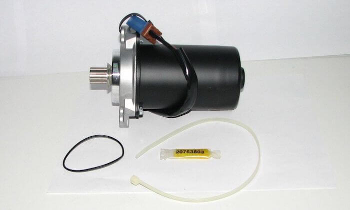
Какова серьезность этого кода неисправности?
Степень серьезности этого кода может сильно варьироваться от просто горящей лампочки проверки двигателя на транспортном средстве, которое работает нормально, до жесткой или неустойчивой проблемы с рулевым управлением. Проблемы с рулевым управлением могут стать проблемой безопасности, если им не уделять немедленного внимания.
Каковы некоторые симптомы кода?
Симптомы кода неисправности P0635 могут включать:
- Жесткое или неустойчивое рулевое управление
- Шум при повороте
- Горит индикатор двигателя Check
Каковы некоторые из распространенных причин появления кода?
Причины этого кода P0635 могут включать:
- Неисправен датчик давления в гидроусилителе рулевого управления.
- Неисправен переключатель положения рулевого управления с гидроусилителем
- Неисправность гидроусилителя рулевого управления
- Ослабленный заземляющий браслет модуля управления или обрыв заземляющего провода.
- Недостаточный уровень жидкости или утечка
- Перегорел предохранитель или перемычка (если применимо)
- Корродированный или поврежденный разъем
- Неисправная или поврежденная проводка
- Неисправный PCM
Каковы некоторые шаги по устранению неполадок P0635?
Первым шагом в процессе поиска и устранения любой неисправности является изучение бюллетеней технического обслуживания (TSB) для конкретного автомобиля с разбивкой по годам, модели и силовой установке. В некоторых случаях это может сэкономить много времени в долгосрочной перспективе, указав вам правильное направление.
Второй шаг — проверить уровень жидкости рулевого управления с гидроусилителем и найти возможные утечки, которые могут отрицательно повлиять на давление, подаваемое на контроллер рулевого управления с гидроусилителем и связанные с ним компоненты. Правильное давление жидкости играет ключевую роль в работе этого контура. Затем найдите все компоненты в этой цепи и выполните тщательный визуальный осмотр, чтобы проверить соответствующую проводку на наличие очевидных дефектов, таких как царапины, потертости, оголенные провода или пятна ожогов. Далее следует проверить разъемы на предмет безопасности, коррозии и повреждений контактов. Этот процесс должен включать контроллер рулевого управления с усилителем, связанные с ним датчики, переключатели и PCM. Состояние сети контроллеров (CAN) имеет важное значение для этого процесса поиска и устранения неисправностей, поскольку поврежденный жгут проводов очень затрудняет выявление неисправных компонентов.
Продвинутые шаги
Дополнительные этапы становятся очень специфичными для автомобиля и требуют соответствующего передового оборудования для точного выполнения. Для этих процедур требуется цифровой мультиметр и специальные технические справочные документы для автомобиля. Требования к напряжению зависят от года выпуска и модели автомобиля.
Проверка напряжения
Для определения диапазонов напряжения, необходимых в цепи управления усилителем рулевого управления, необходимо обращаться к конкретным рекомендациям по поиску и устранению неисправностей. В зависимости от конфигурации включены несколько компонентов рулевого управления с усилителем. Контроллерам гидроусилителя руля, реле давления и датчикам положения для правильной работы требуются разные напряжения в зависимости от конкретного транспортного средства.
Если этот процесс определяет отсутствие источника питания или заземления, может потребоваться проверка целостности цепи для проверки целостности проводки, разъемов и других компонентов. Проверки на непрерывность всегда следует проводить при отключенном от цепи питании, и нормальные показания для проводки и соединений должны составлять 0 Ом сопротивления. Сопротивление или отсутствие непрерывности указывает на неисправную проводку, которая разомкнута или закорочена и требует ремонта или замены.
Каковы стандартные способы устранения этого кода?
- Замена реле давления гидроусилителя руля
- Замена переключателя положения гидроусилителя руля
- Замена перегоревшего предохранителя или плавкой вставки (если применимо)
- Устранить утечку рулевого управления с гидроусилителем
- Очистка разъемов от коррозии
- Ремонт или замена неисправной проводки
- Замена контроллера гидроусилителя руля
- Прошивка или замена PCM
Примечание. Код P0635 часто препятствует правильной связи модуля управления, могут запускаться другие коды неисправностей. Проблемы CAN может быть очень трудно определить, что в некоторых случаях приводит к неправильной диагностике.
Надеюсь, информация в этой статье помогла вам указать правильное направление для устранения проблемы с кодом неисправности цепи усилителя рулевого управления. Эта статья носит исключительно информационный характер, и конкретные технические данные и сервисные бюллетени для вашего автомобиля всегда должны иметь приоритет.
Связанные обсуждения DTC
- В настоящее время на наших форумах нет связанных тем. Разместите новую тему на форуме сейчас.
Нужна дополнительная помощь с кодом P0635?
Если вам все еще нужна помощь по поводу кода неисправности P0635, задайте вопрос в комментариях под этой статьей..
ПРИМЕЧАНИЕ. Эта информация представлена только в информационных целях. Он не предназначен для использования в качестве рекомендаций по ремонту, и мы не несем ответственности за любые действия, которые вы предпринимаете с каким-либо автомобилем. Вся информация на этом сайте защищена авторским правом.
Рассмотрим подробнее
- Техническое описание и расшифровка ошибки P0635
- Симптомы неисправности
- Причины возникновения ошибки
- Как устранить или сбросить код неисправности P0635
- Диагностика и решение проблем
- Проверка проводки
- Проверка вольтомметром
- Проверка давления в гидроусилителе
- На каких автомобилях чаще встречается данная проблема
- Видео
Код ошибки P0635 звучит как «неисправность цепи управления усилителем рулевого управления». Часто, в программах, работающих со сканером OBD-2, название может иметь английское написание «Power Steering Control Circuit Malfunction».
Техническое описание и расшифровка ошибки P0635
Код ошибки OBD-II P0635 является общим кодом, который определяется как неисправность цепи управления усилителем рулевого управления. Устанавливается, когда модуль управления трансмиссией (PCM) обнаруживает неправильные сигналы в цепи управления усилителем рулевого управления.

Современные системы рулевого управления с гидроусилителем являются адаптивными. Усилитель рулевого управления увеличивается на низких скоростях движения, а на высоких скоростях уменьшается или полностью отключается.
Делается это для того, чтобы улучшить обратную связь через системы подвески и рулевое управление. Преимущество этого подхода заключается в том, что улучшается управляемость транспортного средства по направлению. Поскольку в значительной степени предотвращаются внезапные или чрезмерные усилия рулевого управления.
PCM использует сигнальное напряжение в цепи управления гидроусилителем руля для расчета увеличения частоты вращения двигателя. Таким образом, предотвращается остановка двигателя на низких оборотах.
Кроме того, за счет эффективного управления частотой вращения двигателя создается достаточная поддержка рулевого управления. Чтобы сделать возможным маневрирование на низкой скорости без чрезмерного приложения силы к рулевому колесу.
Если PCM не получает сигнал от цепи управления гидроусилителем руля, он установит код P0635. После чего может загореться сигнальная лампа, для которой может потребоваться несколько циклов с отказом.
Симптомы неисправности
Основным симптомом появления ошибки P0635 для водителя является подсветка MIL (индикатор неисправности). Также его называют Check engine или просто «горит чек».
Также они могут проявляться как:
- Загорится контрольная лампа «Check engine» на панели управления (код будет записан в память как неисправность).
- Двигатель может заглохнуть при повороте рулевого колеса на низких оборотах работы.
- Рулевое колесо очень трудно или почти невозможно повернуть на низких скоростях.
- Насос гидроусилителя рулевого управления может издавать шум, завывание, свист или постукивание.
- В некоторых случаях симптомы могут отсутствовать, кроме сохраненного кода неисправности.
Ошибка P0635 является довольно серьезной, так как при ее появлении могут возникнуть проблемы с управляемостью. Поэтому при обнаружении неисправности рекомендуется как можно скорее устранить ошибку.
Причины возникновения ошибки
Код P0635 может означать, что произошла одна или несколько следующих проблем:
- Неисправный датчик давления в гидроусилителе рулевого управления.
- Неисправен переключатель положения рулевого управления с гидроусилителем.
- Неисправность гидроусилителя рулевого управления.
- Сломанный, поврежденный, корродированный жгут проводов.
- Проблема с разъемом или его контактами.
- Неисправно реле или перегоревший предохранитель.
- Низкий уровень жидкости из-за утечек в системе.
- Отказ насоса рулевого управления с гидроусилителем.
- Иногда причиной является неисправный модуль PCM.
Как устранить или сбросить код неисправности P0635
Некоторые предлагаемые шаги для устранения неполадок и исправления кода ошибки P0635:
- Убедитесь, что уровень гидравлической жидкости в норме.
- Проверьте датчик давления в гидроусилителе рулевого управления.
- Протестируйте переключатель положения рулевого управления с гидроусилителем.
- Осмотрите провода и разъемы подключения на наличие повреждений.
- Протестируйте насос гидроусилителя, а также реечную передачу.
- Если ошибка не исчезла, проверьте модуль PCM.
Диагностика и решение проблем
При возникновении ошибки P0635 первым шагом необходимо проверить уровень и внешний вид жидкости в бачке системы рулевого управления. Если уровень в резервуаре значительно ниже отметки, значит в системе есть утечка. Поэтому ее необходимо обнаружить и устранить до того, как автомобиль снова будет введен в эксплуатацию.
Если жидкость темного цвета или имеет запах гари, значит она выработала свой ресурс, ее также необходимо заменить в соответствии с инструкциями, приведенными в руководстве. Имейте в виду, что этот код может быть вызван как низким уровнем жидкости, так и испорченной жидкостью, поэтому уделите время этой проверке.
Проверка проводки
После проверки уровня жидкости и надлежащего состояния в системе не должно быть утечек. Далее, необходимо послушать не исходит ли странных механических шумов при включенном двигателе или когда рулевое колесо поворачивается из стороны в сторону.
Теперь выполните тщательный визуальный осмотр всей связанной проводки и разъемов. Поищите поврежденную, сгоревшую, закороченную, отсоединенную или корродированную проводку, а также разъемы. При необходимости отремонтируйте, если такое повреждение обнаружено.
Удалите код P0635 после проделанных операций и проведите тест-драйв автомобиля на низкой скорости. Также можно поворачивать рулевое колесо из стороны в сторону при работающем двигателе, чтобы проверить, возвращается ли код.
Проверка вольтомметром
Если код остался, но нет видимых повреждений проводки системы управления. Подготовьтесь к выполнению проверок опорного напряжения, целостности, сопротивления и заземления на всей связанной проводке.
При тестировании проводки не забудьте отключить датчик от PCM, чтобы предотвратить повреждение контроллера. Сравните все полученные показания с указанными в руководстве, если обнаружены отклонения, отремонтируйте или замените проводку.
Помимо проводки, протестируйте сам датчик давления, так как он является частью цепи управления. Замените датчик, если его сопротивление отличается от значения, указанного в руководстве.
Проверка давления в гидроусилителе
Если неисправность все еще остается, проверьте фактическое давление, развиваемое насосом рулевого управления с гидроусилителем. Сравните результаты испытаний со значениями, указанными в руководстве.
Имейте в виду, что замена насоса рулевого управления с гидроусилителем в большинстве случаев является технически сложным делом. Поэтому лучше обратиться к профессиональным механикам.
Поэтому, если установлено, что насос не работает в соответствии со спецификациями. Лучший вариант, направить автомобиль к дилеру или в другую компетентную ремонтную мастерскую для получения профессиональной помощи.
Если рулевое колесо поворачивается на малой скорости также как было до появления кода, проблема вряд ли связана с давлением, создаваемым насосом. В этом случае проблема, скорее всего, связана с периодическими электрическими проблемами. Которые иногда бывает чрезвычайно сложно найти и окончательно отремонтировать.
Одна из типичных причин периодических проблем напрямую связана с дешевыми, неоригинальными датчиками давления неопределенного происхождения. И во многих случаях проблема может быть решена путем замены датчика давления на деталь OEM.
Также существует вероятность того, что аномальное напряжение системы может повредить PCM. В таком случае необходимо заменить PCM, перепрограммировать его и проверьте автомобиль. Чтобы увидеть, возвращается ли код ошибки P0635.
На каких автомобилях чаще встречается данная проблема
Проблема с кодом P0635 может встречаться на различных машинах, но всегда есть статистика, на каких марках эта ошибка присутствует чаще. Вот список некоторых из них:
- Dodge
- Ford
- Hyundai
- Mercedes (Мерседес glk)
- Nissan
- Peugeot (Пежо 307)
- Renault
- Saturn
С кодом неисправности Р0635 иногда можно встретить и другие ошибки. Наиболее часто встречаются следующие: P0636, P0637.
Видео
-
#1.626
Strelok написал(а):
Evgen 35 написал(а):
idg83 написал(а):
Ну успокоили спасибо Господа!!!
Он и должен гореть когда холодный мотор, заморгает уже можно ехать , но на малых оборотах , перестал моргать-полный вперед ! Читайте руководство…
Что за бред? когда заводиш — он холодный, индикатор мограет, большими буквами TEMP когда тухнет — двиг прогретый, можно ехать.
Если горит — значит перегрев! и если мне не изменяет память через минуту или сколько-то там электроника заглушит двигатель принудительно!
Не знаю , заводишь холодный он какое то время горит, а потом начинает моргать и уже потом тухнет. Как он может гореть и показывать перегрев движка если он холодный. Вот если он горит когда движок горячий, то может и сигнализирует перегрев, а так как-то не увязочка движок холодный, а он горит и показывает перегрев.
-
#1.627
Strelok написал(а):
Evgen 35 написал(а):
idg83 написал(а):
Ну успокоили спасибо Господа!!!
Он и должен гореть когда холодный мотор, заморгает уже можно ехать , но на малых оборотах , перестал моргать-полный вперед ! Читайте руководство…
Что за бред? когда заводиш — он холодный, индикатор мограет, большими буквами TEMP когда тухнет — двиг прогретый, можно ехать.
Если горит — значит перегрев! и если мне не изменяет память через минуту или сколько-то там электроника заглушит двигатель принудительно!
Ты ,тут сейчас всех напугаешь . А ямахофилы будут радоваться… 
-
#1.628
[/quote]
Поставили такие на XT 2009, на мою Z-ку и на 2 660-х Не сочтите за рекламу, добрый человек посоветовал сайт, www.market-skis.ru заказал 4 комплекта, с доставкой EMS обошлись 13000 руб, ширина 32 см, просто лапти, очень доволен. Один в один как оригинал, только как я понял в москве делают[/quote]
Тоже о них думал, тогда их и возьму, раз нормальные.
Спасибо за отзыв, товарищ!  :)")
-
#1.629
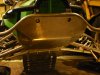
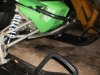
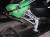
Поставил вот такую защиту, думаю, что будет помогать.
-
2,9 MB
Просмотры: 638 -
2,9 MB
Просмотры: 642 -
2,9 MB
Просмотры: 625 -
2,9 MB
Просмотры: 644
-
#1.630
я что один рыжий? у меня когда запускаеш — сразу мограет, поработает мин 5 гаснет… А из инструкции я понял что когда он именно горит — это перегрев
-
#1.631
Strelok написал(а):
я что один рыжий?
Ты при какой температуре запускаешь ? Может у тебя в гараже тепло, все зависит от температуры ? А про перегрев и первокласснику понятно…
-
#1.632
Защита зачетная , надо тоже такую примастырить 
-
#1.633
Парни, ачто родной защиты не предусмотрено, надо самому что-то химичить.

-
#1.634
ТюнинХ- это состояние души
-
#1.635
Привет всем. Катаюсь второй сезон всего, поэтому сам пока не шарю — решил обратиться за помощью.
Завалился на бок и треснула защита справа. Верхняя часть, пластмассовая, там где решетка находится. Решетка вылетела из-за сильных трещин(
Собственно, нужно поменять этот верхний кусок пластмассы справа.
Делается это, думаю, легко. Сам посмотрел — просто резинки снять и болт открутить.
Отец сказал чинить за свой счет.(
Сколько примерно это будет стоить? Гугл не помог.(
-
#1.636
Пробег 4000 заглючил щиток приборов горит только подсветка и надпись +-LCD стрелка висит на отметке 140 при вкл ключа зажигания никакой диагностики не происходит.Если кто может подсказать подскажите плиз в чем дело?
-
#1.637
ALEKS2010 написал(а):
Катон написал(а):
ALEKS2010 написал(а):
Капрал написал(а):
Саш, все по серьезному у тебя…
Андрей ! Спасибо дружище
Поставил….. !!!!
у меня стоит подальше к багажнику , просто бывают случаи когда нужно подсадить пасажира — тогда как быть ? а так смотриться
уже испробывал, расажир остался доволен — чехол ему не помешал, чехол даже до защиты рук не достал.
-
#1.638
Капрал написал(а):
Катон написал(а):
Al Ksandr написал(а):
защиту на перед хочу .образец нужен,помогите.
Я не стал замарачиваться, защитил рычаги и доп. фары…
Зачетно смотрится!
Доп. фары в пухляке не сносит?

Нет, даже специально испытывал, думал если будет сносить, то поставлю защиту. Иногда когда в пуховые заедешь их забрасывает, но поскольку ксенон холодный, то фары не намерзают. После установки этих фар родная оптика не нужна….
-
#1.639
ALEKS2010 написал(а):
Катон написал(а):
ALEKS2010 написал(а):
Капрал написал(а):
Саш, все по серьезному у тебя…
Андрей ! Спасибо дружище
Поставил….. !!!!
у меня стоит подальше к багажнику , просто бывают случаи когда нужно подсадить пасажира — тогда как быть ? а так смотриться
Спасибо замлячок 
-
#1.640
Strelok написал(а):
я что один рыжий?
У меня тоже самое-завел горит, потом моргает, а потом гаснет в общем не бздии
-
#1.641
Я смотрю тут Котейку кто во что горазд дорабатывает — улучшает. Любо дорого смотреть…
-
#1.642
Принимайте в свои ряды
Сегодня пришел и мой зеленый котик xt
Проехал пару км до заправки и назад
Есть пару вопросов
Так инструкции на русском пока нет
1) как переключить мили на км
2) залил полный бак а на приборке показаний пусто и мигает крайние буквы E и F
Я так понял неработает что можно сделать( дилер далеко в Москве )
Пробку от 570 закажу позже , впечатления позже после хоть немного проехать надо
-
#1.643
Strelok написал(а):
я что один рыжий?
Доброго всем времени суток!
Только месяц назад преобрёл Кота, пока не было снега три раза прочитал инструкцию от корки до корки. Поэтому точно знаю, что после заводки, пока двигатель не нагрелся до рабочей температуры должна гореть надпись TEMP и снегоход не едет, далее по мере нагрева, надпись начинает мигать и когда потухнет — можно ехать.
-
#1.644
Всем привет ,насчет температуры ,заводиш кота лампа температуры должна гореть,если снежок стоит в тепле то через 40-60 секунд лампочка начнет моргать ,и пока не потухнет ехать нерекомендуется,вобще перед поездкой я подключаю подогрев на 20 минут ,лампа гаснет через 30 секунд,вобщем с подогревом удобно,насчет инструкции у меня сразу была на русском и английском 2 книги ,да за 5 минут снежик до перегрева ненагреть,
-
#1.645
Здравствуйте. Всем доброго здоровья! У меня КОТ 2009 года (ещё стоит старый электронный блок ).По показанию температуры так:» Вставляю ключ зажигания,поворачиваю идёт диагностика остаётся значок темпера.после пуска двигателя значок t пропадает.Смотрю на обороты,когда падают до1280-1300 можно начинать движение.Если в прцессе движения снегохода появляется t значит не хватает охлаждения и вскором времени двиг заглохнет. TEMP появляется только при перегреве.
-
#1.646
355f1 написал(а):
Принимайте в свои ряды
Сегодня пришел и мой зеленый котик xt
Проехал пару км до заправки и назад
Есть пару вопросов
Так инструкции на русском пока нет
1) как переключить мили на км
2) залил полный бак а на приборке показаний пусто и мигает крайние буквы E и F
Я так понял неработает что можно сделать( дилер далеко в Москве )
Пробку от 570 закажу позже , впечатления позже после хоть немного проехать надо
Добро пожаловать!!! Инструкцию я скачивал на сайте в разделе тех. документация. Удачи!
-
#1.647
всем привет, очень нравится Z1, хочу его купить,
к сож., диллеры не дают аппарат на тест драйв, поэтому спрашиваю владельцев…
Интересен ли при управлении, динамичен и резв ли этот котик в чистом поле?
Или же это классический утилит — рабочая лошадка, которая покупается скорее как помощник в хозяйстве и средство передвижения, а за скоростью и адреналином надо идти в другой класс снежиков?
заранее спасибо за ответы
-
#1.648
Alexarbat написал(а):
а за скоростью и адреналином надо идти в другой класс снежиков?
для скорости и адреналина нужно купить кроссовый снегоход и катать по кроссовым трассам. 
-
#1.649
Динамики и резвости (на мой взгляд) хватает. Прошлые выходные пробовал на мульте- на нем в сравнении с котом работать нужно, просто так не посидишь. Пробовать самому нужно, у каждого свое субъективное мнение. договоритесь с земляками прокатиться, думаю не откажут.
-
#1.650
Мультик как раз только продал из-за валкости.
Попробовал вентуру ТФ — очень резвая…
Теперь цель купить устойчивый снежик, который при этом быстро едет.
В Z1 нравится ширина трака + мощный мотор.
Code
Fault Description
P0108
MAP Sensor Circuit High/SP
P0112
Intake Air Temp Sensor Circuit Low/SG
P0113
Intake Air Temp Sensor Circuit High/Open
P0114
Intake Air Temp Sensor Circuit Intermittent Sensor or interconnect harness intermittent
P0116
ECT Sensor Circuit Range/Performance
P0117
ECT Sensor Circuit Low/SG
P0118
ECT Sensor Circuit High/Open/SP
P0119
ECT Sensor Circuit Intermittent
P0121
TPS Range/Performance
P0122
TPS Circuit Low/SG
P0123
TPS Circuit High
P0130
O2 Sensor Intermittent/Open
P0131
O2 Sensor Low/SG or Air-Leak
P0132
O2 Sensor High/SP
P0171
O2 Feedback Below Minimum Correction
P0172
O2 Feedback Exceeds Maximum Correction Excessive fuel rail pressure, MAP or temp sensors out-of-spec
P0219
Engine Over-Speed Condition
P0231
Fuel Pump Relay Circuit Low/SG/Open
P0232
Fuel Pump Relay Circuit High
P0233
Fuel Pump Relay Circuit
P0261
Cylinder Fuel injector Circuit Low/SG
P0262
Cylinder Fuel injector Circuit High
P0263
Cylinder Fuel injector Balance/Open
P0336
Crankshaft Angle Sensor Synchronization
P0337
Crankshaft Angle Sensor Circuit/SG
P0339
Crankshaft Angle Sensor Intermittent/Erratic Sensor or interconnect harness intermittent
P0340
Camshaft Angle Sensor Synchronization
P0341
Camshaft Angle Sensor Circuit/SG
P0342
Camshaft Angle Sensor Intermittent/Erratic Sensor or interconnect harness intermittent
P0480
Fan Relay Control Circuit
P0484
Fan Relay Control Circuit High
P0485
Fan Relay Control Circuit Low/SG/Open
P0500
Vehicle Speed-Sensor
P0508
Idle Air Control System Circuit Low/SG
P0509
Idle Air Control System Circuit High/Open
P0520
Engine Oil Sensor/Switch
P0562
System Voltage Low
P0563
System Voltage High
P0601
ECU Memory Check-Sum Error
P0615
Starter Relay Circuit
P0616
Starter Relay Circuit Low
P0617
Starter Relay Circuit High
P0630
VIN Not Programmed or Incompatible
P0642
Sensor Power Circuit Low
P0643
Sensor Power Circuit High
P2300
Ignition Coil Primary Circuit Low/SG/Open Coil or interconnect harness open or shorted to chassis ground
P2301
Ignition Coil Primary Circuit High
P2531
Ignition Switch Circuit Low
P2532
Ignition Switch Circuit High
U0155
LCD Gauge to EFI ECM CAN Communica-
tion Lost
U1000
Vehicle Not Registered or Invalid PIN
Entered
U1001
Vehicle Not Registered and Vehicle Limits
Enabled
FUEL OFF Tilt Sensor Activation Code
High: A high voltage condition has been detected
Low: A low voltage condition has been detected
Intermittent: An intermittent circuit condition has been detected
Open: An or open circuit condition has been detected
Possible Cause
Sensor or interconnect harness shorted to battery power
Sensor or interconnect harness shorted to chassis ground
Sensor or interconnect harness open or shorted to battery power
Sensor producing an out-of-range voltage
Sensor or interconnect harness shorted to chassis ground
Sensor or interconnect harness open or shorted to battery power
Sensor or interconnect harness intermittent
Sensor producing an out-of-range voltage
Sensor or interconnect harness shorted to chassis ground
Sensor or interconnect harness open or shorted to battery power
Sensor or interconnect harness intermittent or open
Sensor or interconnect harness shorted to chassis ground or an air-
leak exists
Sensor or interconnect harness shorted to battery power
Low fuel rail pressure, dirty fuel filter, or dirty injectors
Engine speed (RPM) has exceeded the ECM over-speed setpoint/
limit
Relay removed or interconnect harness shorted to chassis ground Correct condition*
Relay or interconnect harness shorted to battery power
Relay circuit erratic or intermittent
Injector or interconnect harness shorted to chassis ground
Injector or interconnect harness shorted to battery power
Injector disconnected or interconnect harness open
Sensor or interconnect harness intermittent
Sensor or interconnect harness shorted to chassis ground
Sensor or interconnect harness intermittent
Sensor or interconnect harness shorted to chassis ground
Relay erratic or intermittent
Relay or interconnect harness shorted to battery power
Fan fuse has blown, fan relay removed, or interconnect harness
shorted to chassis ground
Sensor circuit signal intermittent or missing
IAC interconnect harness shorted to chassis ground
IAC disconnected or the interconnect harness shorted to battery power Correct condition*
Sensor or interconnect harness erratic or intermittent
Battery charge condition low or the regulator/rectifier output low
Battery cable connections are loose or regulator/rectifier output high Correct condition*
Reflash the ECM with the current software version
Start switch/button, starter relay, gear switch or interconnect har-
ness erratic or intermittent
Start switch/button, starter relay or interconnect harness intermittent
or shorted to chassis ground
Start switch/button, starter relay or interconnect harness intermittent
or shorted to battery power
Verify the LCD gauge and ECM part numbers are correct for the
vehicle model number and VIN
One or more of the sensors defective or shorted to chassis ground Correct condition*
One or more of the sensors defective or shorted to battery power
Coil or interconnect harness shorted to battery power
Battery charge condition low or the regulator/rectifier output low
Battery cable connections are loose or regulator/rectifier output high Correct condition*
Gauge CAN circuit or interconnect harness intermittent or has failed Correct condition*
An invalid registration PIN has been entered
An invalid registration PIN has been entered
Sensor activated
* After correcting the condition, cycle the key switch On-Off-On
**After correcting the condition, cycle the key switch On-Off-On,
start the engine, then cycle the key switch On-Off-On.
Fault Recovery
Correct condition*
Correct condition*
Correct condition*
Correct condition*
Correct condition*
Correct condition*
Correct condition*
Correct condition*
Correct condition*
Correct condition*
Correct condition*
Correct condition*
Correct condition*
Correct condition*
Correct condition*
Correct condition*
Reduce engine speed
Correct condition*
Correct condition*
Correct condition**
Correct condition**
Correct condition**
Correct condition**
Correct condition**
Correct condition**
Correct condition**
Correct condition**
Correct condition**
Correct condition*
Correct condition*
Correct condition*
Correct condition*, start
and drive the vehicle*
Correct condition*
Correct condition*
Correct condition*
Correct ECM software
issue*
Correct condition*
Correct condition*
Correct condition*
Correct gauge and ECM
VIN compatibility issue*
Correct condition*
Correct condition**
Correct condition**
Correct condition*
Enter the correct regis-
tration PIN*
Enter the correct regis-
tration PIN*
Restore the vehicle chas-
sis to an upright position*
99
-
#1.626
Strelok написал(а):
Evgen 35 написал(а):
idg83 написал(а):
Ну успокоили спасибо Господа!!!
Он и должен гореть когда холодный мотор, заморгает уже можно ехать , но на малых оборотах , перестал моргать-полный вперед ! Читайте руководство…
Что за бред? когда заводиш — он холодный, индикатор мограет, большими буквами TEMP когда тухнет — двиг прогретый, можно ехать.
Если горит — значит перегрев! и если мне не изменяет память через минуту или сколько-то там электроника заглушит двигатель принудительно!
Не знаю , заводишь холодный он какое то время горит, а потом начинает моргать и уже потом тухнет. Как он может гореть и показывать перегрев движка если он холодный. Вот если он горит когда движок горячий, то может и сигнализирует перегрев, а так как-то не увязочка движок холодный, а он горит и показывает перегрев.
-
#1.627
Strelok написал(а):
Evgen 35 написал(а):
idg83 написал(а):
Ну успокоили спасибо Господа!!!
Он и должен гореть когда холодный мотор, заморгает уже можно ехать , но на малых оборотах , перестал моргать-полный вперед ! Читайте руководство…
Что за бред? когда заводиш — он холодный, индикатор мограет, большими буквами TEMP когда тухнет — двиг прогретый, можно ехать.
Если горит — значит перегрев! и если мне не изменяет память через минуту или сколько-то там электроника заглушит двигатель принудительно!
Ты ,тут сейчас всех напугаешь . А ямахофилы будут радоваться…
-
#1.628
[/quote]
Поставили такие на XT 2009, на мою Z-ку и на 2 660-х Не сочтите за рекламу, добрый человек посоветовал сайт, www.market-skis.ru заказал 4 комплекта, с доставкой EMS обошлись 13000 руб, ширина 32 см, просто лапти, очень доволен. Один в один как оригинал, только как я понял в москве делают[/quote]
Тоже о них думал, тогда их и возьму, раз нормальные.
Спасибо за отзыв, товарищ!
-
#1.629
Поставил вот такую защиту, думаю, что будет помогать.
-
2,9 MB
Просмотры: 646 -
2,9 MB
Просмотры: 651 -
2,9 MB
Просмотры: 633 -
2,9 MB
Просмотры: 655
-
#1.630
я что один рыжий? у меня когда запускаеш — сразу мограет, поработает мин 5 гаснет… А из инструкции я понял что когда он именно горит — это перегрев
-
#1.631
Strelok написал(а):
я что один рыжий?
Ты при какой температуре запускаешь ? Может у тебя в гараже тепло, все зависит от температуры ? А про перегрев и первокласснику понятно…
-
#1.632
Защита зачетная , надо тоже такую примастырить
-
#1.633
Парни, ачто родной защиты не предусмотрено, надо самому что-то химичить.
-
#1.634
ТюнинХ- это состояние души
-
#1.635
Привет всем. Катаюсь второй сезон всего, поэтому сам пока не шарю — решил обратиться за помощью.
Завалился на бок и треснула защита справа. Верхняя часть, пластмассовая, там где решетка находится. Решетка вылетела из-за сильных трещин(
Собственно, нужно поменять этот верхний кусок пластмассы справа.
Делается это, думаю, легко. Сам посмотрел — просто резинки снять и болт открутить.
Отец сказал чинить за свой счет.(
Сколько примерно это будет стоить? Гугл не помог.(
-
#1.636
Пробег 4000 заглючил щиток приборов горит только подсветка и надпись +-LCD стрелка висит на отметке 140 при вкл ключа зажигания никакой диагностики не происходит.Если кто может подсказать подскажите плиз в чем дело?
-
#1.637
ALEKS2010 написал(а):
Катон написал(а):
ALEKS2010 написал(а):
Капрал написал(а):
Саш, все по серьезному у тебя…
Андрей ! Спасибо дружище
Поставил….. !!!!
у меня стоит подальше к багажнику , просто бывают случаи когда нужно подсадить пасажира — тогда как быть ? а так смотриться
уже испробывал, расажир остался доволен — чехол ему не помешал, чехол даже до защиты рук не достал.
-
#1.638
Капрал написал(а):
Катон написал(а):
Al Ksandr написал(а):
защиту на перед хочу .образец нужен,помогите.
Я не стал замарачиваться, защитил рычаги и доп. фары…
Зачетно смотрится!
Доп. фары в пухляке не сносит?
Нет, даже специально испытывал, думал если будет сносить, то поставлю защиту. Иногда когда в пуховые заедешь их забрасывает, но поскольку ксенон холодный, то фары не намерзают. После установки этих фар родная оптика не нужна….
-
#1.639
ALEKS2010 написал(а):
Катон написал(а):
ALEKS2010 написал(а):
Капрал написал(а):
Саш, все по серьезному у тебя…
Андрей ! Спасибо дружище
Поставил….. !!!!
у меня стоит подальше к багажнику , просто бывают случаи когда нужно подсадить пасажира — тогда как быть ? а так смотриться
Спасибо замлячок
-
#1.640
Strelok написал(а):
я что один рыжий?
У меня тоже самое-завел горит, потом моргает, а потом гаснет в общем не бздии
-
#1.641
Я смотрю тут Котейку кто во что горазд дорабатывает — улучшает. Любо дорого смотреть…
-
#1.642
Принимайте в свои ряды
Сегодня пришел и мой зеленый котик xt
Проехал пару км до заправки и назад
Есть пару вопросов
Так инструкции на русском пока нет
1) как переключить мили на км
2) залил полный бак а на приборке показаний пусто и мигает крайние буквы E и F
Я так понял неработает что можно сделать( дилер далеко в Москве )
Пробку от 570 закажу позже , впечатления позже после хоть немного проехать надо
-
#1.643
Strelok написал(а):
я что один рыжий?
Доброго всем времени суток!
Только месяц назад преобрёл Кота, пока не было снега три раза прочитал инструкцию от корки до корки. Поэтому точно знаю, что после заводки, пока двигатель не нагрелся до рабочей температуры должна гореть надпись TEMP и снегоход не едет, далее по мере нагрева, надпись начинает мигать и когда потухнет — можно ехать.
-
#1.644
Всем привет ,насчет температуры ,заводиш кота лампа температуры должна гореть,если снежок стоит в тепле то через 40-60 секунд лампочка начнет моргать ,и пока не потухнет ехать нерекомендуется,вобще перед поездкой я подключаю подогрев на 20 минут ,лампа гаснет через 30 секунд,вобщем с подогревом удобно,насчет инструкции у меня сразу была на русском и английском 2 книги ,да за 5 минут снежик до перегрева ненагреть,
-
#1.645
Здравствуйте. Всем доброго здоровья! У меня КОТ 2009 года (ещё стоит старый электронный блок ).По показанию температуры так:» Вставляю ключ зажигания,поворачиваю идёт диагностика остаётся значок темпера.после пуска двигателя значок t пропадает.Смотрю на обороты,когда падают до1280-1300 можно начинать движение.Если в прцессе движения снегохода появляется t значит не хватает охлаждения и вскором времени двиг заглохнет. TEMP появляется только при перегреве.
-
#1.646
355f1 написал(а):
Принимайте в свои ряды
Сегодня пришел и мой зеленый котик xt
Проехал пару км до заправки и назад
Есть пару вопросов
Так инструкции на русском пока нет
1) как переключить мили на км
2) залил полный бак а на приборке показаний пусто и мигает крайние буквы E и F
Я так понял неработает что можно сделать( дилер далеко в Москве )
Пробку от 570 закажу позже , впечатления позже после хоть немного проехать надо
Добро пожаловать!!! Инструкцию я скачивал на сайте в разделе тех. документация. Удачи!
-
#1.647
всем привет, очень нравится Z1, хочу его купить,
к сож., диллеры не дают аппарат на тест драйв, поэтому спрашиваю владельцев…
Интересен ли при управлении, динамичен и резв ли этот котик в чистом поле?
Или же это классический утилит — рабочая лошадка, которая покупается скорее как помощник в хозяйстве и средство передвижения, а за скоростью и адреналином надо идти в другой класс снежиков?
заранее спасибо за ответы
-
#1.648
Alexarbat написал(а):
а за скоростью и адреналином надо идти в другой класс снежиков?
для скорости и адреналина нужно купить кроссовый снегоход и катать по кроссовым трассам.
-
#1.649
Динамики и резвости (на мой взгляд) хватает. Прошлые выходные пробовал на мульте- на нем в сравнении с котом работать нужно, просто так не посидишь. Пробовать самому нужно, у каждого свое субъективное мнение. договоритесь с земляками прокатиться, думаю не откажут.
-
#1.650
Мультик как раз только продал из-за валкости.
Попробовал вентуру ТФ — очень резвая…
Теперь цель купить устойчивый снежик, который при этом быстро едет.
В Z1 нравится ширина трака + мощный мотор.
Open the PDF directly: View PDF ![]() .
.
Page Count: 210 [warning: Documents this large are best viewed by clicking the View PDF Link!]

FOREWORD
This Arctic Cat Service Manual contains service, maintenance, and troubleshooting information for certain 2012
Arctic Cat ATV models (see cover). The complete manual is designed to aid service personnel in service-oriented
applications.
Arctic Cat offers additional publications (when they become available) to aid in servicing other ATV models. To
service models not included in this manual, please refer to the following publications:
• 2012 Y-12+ Service Manual
• 2012 T-14 Service Manual
• 2012 300 DVX/Utility Service Manual
• 2012 350 Service Manual
• 2012 425 Service Manual
• 2012 700 Diesel Service Manual
• 2012 450 XC Service Manual
• 2012 650 Service Manual
• 2012 550/700 Service Manual
This manual is divided into sections. Each section covers a specific ATV component or system and, in addition to
the standard service procedures, includes disassembling, inspecting, and assembling instructions. When using this
manual as a guide, the technician should use discretion as to how much disassembly is needed to correct any given
condition.
The service technician should become familiar with the operation and construction of each component or system
by carefully studying the complete manual. This manual will assist the service technician in becoming more aware
of and efficient with servicing procedures. Such efficiency not only helps build consumer confidence but also saves
time and labor.
All Arctic Cat ATV publications and decals display the words Warning, Caution, Note, and At This Point to
emphasize important information. The symbol ! WARNING identifies personal safety-related information.
Be sure to follow the directive because it deals with the possibility of severe personal injury or even death. A
CAUTION identifies unsafe practices which may result in ATV-related damage. Follow the directive because it
deals with the possibility of damaging part or parts of the ATV. The symbol NOTE: identifies supplementary
information worthy of particular attention. The symbol AT THIS POINT directs the technician to certain
and specific procedures to promote efficiency and to improve clarity.
At the time of publication, all information, photographs, and illustrations were technically correct. Some photo-
graphs used in this manual are used for clarity purposes only and are not designed to depict actual conditions.
Because Arctic Cat Inc. constantly refines and improves its products, no retroactive obligation is incurred.
All materials and specifications are subject to change without notice.
Keep this manual accessible in the shop area for reference.
Product Service and
Warranty Department
Arctic Cat Inc.
© 2011 Arctic Cat Inc. August 2011
®™ Trademarks of Arctic Cat Inc., Thief River Falls, MN 56701
FOR ARCTIC CAT ATV DISCOUNT PARTS CALL 606-678-9623 OR 606-561-4983
www.mymowerparts.com
TABLE OF CONTENTS
‘PSFXPSE
1. General Information/Specifications
2. Periodic Maintenance
3. Engine/Transmission
4. Fuel/Lubrication/Cooling
5. Electrical System
6. Drive System/Brake System
7. Suspension
8. Steering/Frame
1
2
3
4
5
6
7
8
FOR ARCTIC CAT ATV DISCOUNT PARTS CALL 606-678-9623 OR 606-561-4983
www.mymowerparts.com
Note: To navigate through this manual, use the PAGE UP/PAGE DOWN buttons on the keyboard, click on the
Table of Contents bookmarks on the left side of the screen, or click the blue text below. To return to this page,
click the Manual Table of Contents button at the bottom of each page.
Click on the blue text to go.

1-1
1
SECTION 1 — GENERAL INFORMATION/
SPECIFICATIONS
TABLE OF CONTENTS
General Specifications ……………..…………….……….. 1-2
Torque Specifications ……………….…………….……….. 1-3
Torque Conversions (ft-lb/N-m) ….…………….……….. 1-4
Break-In Procedure ………………………….………….….. 1-4
Gasoline — Oil — Lubricant ………………….………….….. 1-5
Genuine Parts …….…………….………….…………….….. 1-5
Preparation For Storage……..…………….……………... 1-6
Preparation After Storage………………….……………... 1-6
FOR ARCTIC CAT ATV DISCOUNT PARTS CALL 606-678-9623 OR 606-561-4983
www.mymowerparts.com

1-2
General Specifications
Specifications subject to change without notice.
* One inch below plug threads.
** At the plug threads.
450
CHASSIS
Brake Type Hydraulic w/Brake Lever
Lock and Auxiliary Brake
Tire Size Front — 25 x 8-12
Rear — 25 x 10-12
Tire Inflation Pressure 0.35 kg/cm² (5 psi)
MISCELLANY
Spark Plug Type NGK CR7E
Spark Plug Gap 0.7-0.8 mm (0.028-0.031 in.)
Gas Tank Capacity 21.6 L (5.7 U.S. gal.) — FIS
20.0 L (5.3 U.S. gal.) — TRV
Coolant Capacity 2.9 L (3.0 U.S. qt)
Rear Drive Capacity 250 ml (8.5 fl oz)*
Front Differential Capacity 275 ml (9.3 fl oz)**
Engine Oil Capacity (approx) 2.85 L (3.0 U.S. qt) —
Overhaul
2.50 L (2.6 U.S. qt) — Change
Gasoline (recommended) 87 Octane Regular
Unleaded
Engine Oil (recommended) Arctic Cat ACX All Weather
(Synthetic)
Differential/Rear Drive Lubricant SAE Approved 80W-90
Hypoid
Drive Belt Width (minimum) 28.5 mm (1.12 in.)
Brake Fluid DOT 4
Taillight/Brakelight 12V/8W/27W
Headlight 12V/37W (2)
ELECTRICAL SYSTEM
Ignition Timing 10° BTDC @ 1500 RPM
Spark Plug Cap 5000 ohms
Ignition Coil (primary)
Resistance
(secondary)
Less than 5.0 ohms
(terminal (+) to terminal (-))
12k-19k ohms (high tension —
plug cap — to terminal (+))
Ignition Coil Primary Voltage Battery Voltage
(orange (+) to blue/white(-))
Stator Coil (crankshaft position sensor)
Resistance
(AC generator)
150-250 ohms (blue to
green)
Less than 1 ohm (yellow to
yellow)
Crankshaft Position Sensor AC Voltage 2.0 volts or more (blue to
green)
AC Generator Output (no load) 75 AC volts @ 5000 RPM
(yellow to yellow)
1000
CHASSIS
Brake Type Hydraulic w/Brake Lever
Lock and Auxiliary Brake
Tire Size
(Mud Pro)
(Mud Pro)
(Cruiser)
(Cruiser)
Front — 25 x 9-12
Rear — 25 x 11-12
Front — 28 x 9-14
Rear — 28 x 11-14
Front — 25 x 8-12
Rear — 25 x 10-12
Tire Inflation Pressure 0.35 kg/cm² (5 psi) — Mud Pro
0.49 kg/cm² (7 psi) — TRV/
Cruiser
MISCELLANY
Spark Plug Type NGK CPR8E
Spark Plug Gap 0.5-0.6 mm (0.019-0.024 in.)
Gas Tank Capacity 21.6 L (5.7 U.S. gal.) — FIS
20.0 L (5.3 U.S. gal.) —
Cruiser/TRV
Coolant Capacity 3.3 L (3.5 U.S. qt)
Differential Capacity 275 ml (9.3 fl oz)*
Rear Drive Capacity 250 ml (8.5 fl oz)**
Engine Oil
Capacity (approx)
2.6 L (2.75 U.S. qt) —
Overhaul
1.9 L (2.0 U.S. qt) — Change
Gasoline (recommended) 87 Octane Regular
Unleaded
Engine Oil (recommended) Arctic Cat ACX All Weather
(Synthetic)
Front Differential/Rear Drive Lubricant SAE Approved 80W-90
Hypoid
Drive Belt Width (minimum) 35.6 mm (1.40 in.)
Brake Fluid DOT 4
Taillight/Brakelight 12V/8W/27W
Headlight 12V/27W (2)
ELECTRICAL SYSTEM
Ignition Timing 10° BTDC @ 1500 RPM
Spark Plug Cap 5000 ohms
Ignition Coil (primary)
Resistance
(secondary)
4.8 ohms (terminal (+) to
terminal (-))
12k-19k ohms (high tension —
plug cap to terminal)
Ignition Coil
Primary Voltage
Battery Voltage
(orange to ground)
Stator Coil (crankshaft position sensor)
Resistance
(AC generator)
150-250 ohms (blue to
green)
Less than 1 ohm (gray to
gray)
Crankshaft Position Sensor
AC Voltage
2.0 volts or more
(blue to green)
Generator Output (no load) 75 AC volts or more
@ 5000 RPM (
black to black
)
FOR ARCTIC CAT ATV DISCOUNT PARTS CALL 606-678-9623 OR 606-561-4983
www.mymowerparts.com

1-3
1
Torque Specifications
* w/Blue Loctite #243
** w/Red Loctite #271
*** w/Green Loctite #609
**** w/Three Bond Sealant
EXHAUST COMPONENTS
Part Part Bolted To Torque
ft-lb N-m
Exhaust Pipe Engine 20 27
Spark Arrester Muffler 48
in.-lb
5.5
ELECTRICAL COMPONENTS
Engine/Harness Ground Cap
Screw
Crankcase 8 11
Coil Air Filter Housing 7 10
STEERING COMPONENTS
Steering Post Bearing
Housing
Frame 20 27
Steering Post Bearing Flange Frame 20 27
Lower Steering Bearing
Washer Cap Screw***
Steering Post 40 54
Tie Rod End Knuckle/Steering Post 30 41
EPS Housing Frame 35 47
BRAKE COMPONENTS
Brake Disc* Hub 15 20
Brake Hose Caliper 20 27
Brake Hose (Banjo-Fitting) Master Cylinder 20 27
Brake Hose Auxiliary Brake Cylinder 20 27
Master Cylinder (Rear) Frame 12 16
Hydraulic Caliper Knuckle
(w/“Patch-Lock”)
20 27
Master Cylinder Clamp Master Cylinder 6 8
Brake Pedal Brake Pedal Axle 25 34
CHASSIS COMPONENTS
Footrest Frame (8 mm) 20 27
Footrest Frame (10 mm) 40 54
SUSPENSION COMPONENTS (Front)
A-Arm Frame 50 68
Knuckle Ball Joint 35 47
Shock Absorber Frame/Upper A-Arm 50 68
Knuckle A-Arm 50 68
SUSPENSION COMPONENTS (Rear)
Shock Absorber (Upper) Frame 50 68
Shock Absorber (Lower) Lower A-Arm 20 27
A-Arm Frame 50 68
Knuckle (450) A-Arm 35 47
Knuckle (1000) A-Arm 50 68
DRIVE TRAIN COMPONENTS
(450)
Part Part Bolted To Torque
ft-lb N-m
Engine Mounting Through-Bolt Frame 35 47
Front Differential Frame/Differential
Bracket
38 52
Output Flange Rear Flange Output
Joint
20 27
Pinion Housing Differential Housing 23 31
Differential Housing Cover*** Differential Housing 23 31
Drive Bevel Gear Nut** Shaft 72 98
Lock Collar Differential Housing 125 169
Hub Hex Nut Shaft/Axle (max) 200 272
Oil Drain Plug Front Differential/Rear
Drive
45
in.-lb
5
Oil Fill Plug Front Differential/Rear
Drive
16 22
Oil Drain Plug Engine 16 22
Rear Drive Input Shaft/Housing Differential Housing 23 31
Wheel (Steel) Hub 40 54
Wheel (Aluminum) Hub 80 108
Rear Drive Gear Case Frame 38 52
Engine Output Shaft** Rear Gear Case Input
Flange
20 27
ENGINE/TRANSMISSION
(450)
Clutch Shoe** Crankshaft 147 199
Clutch Cover/Housing
Assembly
Crankcase 8 11
Left-Side Cover Crankcase 8 11
Crankcase Half (6 mm) Crankcase Half 10 13.5
Crankcase Half (8 mm) Crankcase Half 21 28
Cylinder Nut Crankcase Half 8 11
Cylinder Head (Cap Screw) Crankcase 28 38
Cylinder Head Nut Cylinder 20 27
Valve Cover**** Cylinder Head 8 11
Oil Pump Drive Gear** Crankshaft 63 86
Driven Pulley Nut** Driveshaft 147 199
Ground Cable Engine 8 11
Output Shaft Flange Nut Output Shaft 59 80
Magneto Rotor Nut Crankshaft 107 146
Cam Sprocket** Camshaft 11 15
Cam Chain Tensioner Guide Cylinder 11 15
Stator Coil** Crankcase 8 11
Starter Motor Crankcase 8 11
V-Belt Cover Crankcase 8 11
Valve Adjuster Jam Nut Valve Adjuster 7 9.5
Oil Fitting Engine 8 11
Oil Pump** Crankcase 8 11
Tappet Cover Valve Cover 8 11
Cam Chain Tensioner Cylinder 10 13.5
Magneto Cover Crankcase 8 11
Rear Driveline Output Drive Flange 20 27
Starter One-Way Clutch** Flywheel 26 35
Movable Drive Face Nut** Clutch Shaft 147 199
Water Pump Cover/Housing Magneto Cover 8 11
Water Pump Drive Gear Crankshaft 28 38
FOR ARCTIC CAT ATV DISCOUNT PARTS CALL 606-678-9623 OR 606-561-4983
www.mymowerparts.com

1-4
* w/Blue Loctite #243
** w/Red Loctite #271
*** w/Green Loctite #609
**** w/Three Bond Sealant
Torque Conversions
(ft-lb/N-m)
Break-In Procedure
A new ATV and an overhauled ATV engine require a
“break-in” period. The first 10 hours (or 200 miles) are
most critical to the life of this ATV. Proper operation dur—
ing this break-in period will help assure maximum life
and performance from the ATV.
During the first 10 hours (or 200 miles) of operation,
always use less than 1/2 throttle. Varying the engine
RPM during the break-in period allows the components
to “load” (aiding the mating process) and then “unload”
(allowing components to cool). Although it is essential to
place some stress on the engine components during
break-in, care should be taken not to overload the engine
too often. Do not pull a trailer or carry heavy loads dur-
ing the 10-hour break-in period.
When the engine starts, allow it to warm up properly. Idle
the engine several minutes until the engine has reached
normal operating temperature. Do not idle the engine for
excessively long periods of time.
DRIVE TRAIN COMPONENTS (1000)
Part Part Bolted To Torque
ft-lb N-m
Engine Mount (Rear) Frame 45 61
Front Differential Frame/Differential
Bracket
38 52
Rear Gear Case Frame 38 52
Pinion Housing Differential Housing 23 31
Differential Housing Cover*** Differential Housing 23 31
Lock Collar Differential Housing 125 169
Hub Nut Shaft/Axle (max) 200 272
Oil Drain Plug Front Differential/
Rear Drive
45
in.-lb
5
Oil Fill Plug Front Differential/
Rear Drive
16 22
Oil Drain Plug Engine 16 22
Wheel (Steel) Hub 40 54
Wheel (Aluminum) Hub 80 108
Rear Drive Input Shaft/Housing Differential Housing 23 31
Rear Output Drive Flange Rear Yoke Flange 20 27
Shift Cam Stopper Shift Stopper 8 11
Shift Cam Plate Shift Cam Shaft 8 11
Shifter Housing Crankcase 8 11
Engine Output Shaft** Rear Gear Case
Input Flange
20 27
ENGINE/TRANSMISSION (1000)
Clutch Shoe** Crankshaft 221 300
Clutch Cover/Housing Assembly Crankcase 811
Crankcase Half Crankcase Half 811
Crankcase Lower Cover (6 mm) Crankcase 811
Crankcase Lower Cover (8 mm) Crankcase 20 27
Cylinder Head (Cap Screw) Crankcase 37 50
Cylinder Head (6 mm) Cylinder 811
Cylinder Head (8 mm) Cylinder 18 24
Cylinder Head Cover Cylinder Head 8.5 11.5
Driven Pulley Nut** Driveshaft 80 108
Ground Wire Engine 811
Magneto Cover Crankcase 811
Oil Filler Cover Crankcase 811
Speed Sensor Housing Crankcase 811
Starter Motor Crankcase 811
V-Belt Housing Crankcase 811
Intake Manifold Cylinder 811
Output Shaft Yoke Nut Output Shaft 59 80
Rotor/Flywheel Nut Crankshaft 107 145
Cam Sprocket** Camshaft 10 13.5
V-Belt Cover Clutch Cover 811
Movable Drive Face Nut** Clutch Shaft 165 224
Oil Pump Cover* Crankcase 811
Oil Strainer Cap Crankcase 811
Shift Cam Stopper Crankcase 811
Shift Cam Stopper Spring Shift Cam Stopper 811
Shift Cam Plate Shift Cam Shaft 811
Shifter Housing Crankcase 811
Secondary Drive Gear Nut Gear 74 100
Starter One-Way Clutch** Flywheel 26 35
Output Yoke Nut Output Shaft 74 100
ft-lb N-m ft-lb N-m ft-lb N-m ft-lb N-m
11.4 26 35.4 51 69.4 76 103.4
22.7 27 36.7 52 70.7 77 104.7
34.1 28 38.1 53 72.1 78 106.1
45.4 29 39.4 54 73.4 79 107.4
56.8 30 40.8 55 74.8 80 108.8
68.2 31 42.2 56 76.2 81 110.2
79.5 32 43.5 57 77.5 82 111.5
810.9 33 44.9 58 78.9 83 112.9
912.2 34 46.2 59 80.2 84 114.2
10 13.6 35 47.6 60 81.6 85 115.6
11 15 36 49 61 83 86 117
12 16.3 37 50.3 62 84.3 87 118.3
13 17.7 38 51.7 63 85.7 88 119.7
14 19 39 53 64 87 89 121
15 20.4 40 54.4 65 88.4 90 122.4
16 21.8 41 55.8 66 89.8 91 123.8
17 23.1 42 57.1 67 91.1 92 125.1
18 24.5 43 58.5 68 92.5 93 126.5
19 25.8 44 59.8 69 93.8 94 127.8
20 27.2 45 61.2 70 95.2 95 129.2
21 28.6 46 62.6 71 96.6 96 130.6
22 29.9 47 63.9 72 97.9 97 131.9
23 31.3 48 65.3 73 99.3 98 133.3
24 32.6 49 66.6 74 100.6 99 134.6
25 34 50 68 75 102 100 136
FOR ARCTIC CAT ATV DISCOUNT PARTS CALL 606-678-9623 OR 606-561-4983
www.mymowerparts.com

1-5
1
During the break-in period, a maximum of 1/2 throttle is
recommended; however, brief full-throttle accelerations
and variations in driving speeds contribute to good
engine break-in.
After the completion of the break-in period, the engine
oil and oil filter should be changed. Other maintenance
after break-in should include checking of all prescribed
adjustments and tightening of all fasteners (see Periodic
Maintenance Chart in Section 2).
Gasoline — Oil — Lubricant
RECOMMENDED GASOLINE
The recommended gasoline to use is 87 minimum octane
regular unleaded. In many areas, oxygenates (either etha—
nol or MTBE) are added to the gasoline. Oxygenated
gasolines containing up to 10% ethanol, 5% methane, or
5% MTBE are acceptable gasolines.
When using ethanol blended gasoline, it is not necessary
to add a gasoline antifreeze since ethanol will prevent the
accumulation of moisture in the fuel system.
RECOMMENDED ENGINE/
TRANSMISSION OIL
The recommended oil to use is Arctic Cat ACX All
Weather synthetic engine oil, which has been specifically
formulated for use in this Arctic Cat engine. Although
Arctic Cat ACX All Weather synthetic engine oil is the
only oil recommended for use in this engine, use of any
API certified SM 0W-40 oil is acceptable.
OILCHARTJ
RECOMMENDED FRONT
DIFFERENTIAL/REAR DRIVE
LUBRICANT
The recommended lubricant is Arctic Cat Gear Lube or
an equivalent gear lube which is SAE approved 80W-90
hypoid. This lubricant meets all of the lubrication
requirements of the Arctic Cat ATV front differentials
and rear drives.
FILLING GAS TANK
Since gasoline expands as its temperature rises, the gas
tank must be filled to its rated capacity only. Expansion
room must be maintained in the tank particularly if the
tank is filled with cold gasoline and then moved to a
warm area.
ATV0049B
Tighten the gas tank cap securely after filling the tank.
Genuine Parts
When replacement of parts is necessary, use only genuine
Arctic Cat ATV parts. They are precision-made to ensure
high quality and correct fit. Refer to the appropriate Illus-
trated Parts Manual for the correct part number, quantity,
and description.
CAUTION
Do not use white gas. Only Arctic Cat approved gaso-
line additives should be used.
CAUTION
Any oil used in place of the recommended oil could
cause serious engine damage. Do not use oils which
contain graphite or molybdenum additives. These oils
can adversely affect clutch operation. Also, not recom-
mended are racing, vegetable, non-detergent, and cas-
tor-based oils.
CAUTION
Any lubricant used in place of the recommended lubri-
cant could cause serious front differential/rear drive
damage.
! WARNING
Always fill the gas tank in a well-ventilated area. Never
add fuel to the ATV gas tank near any open flames or
with the engine running. DO NOT SMOKE while filling
the gas tank.
! WARNING
Do not overflow gasoline when filling the gas tank. A
fire hazard could materialize. Always allow the engine to
cool before filling the gas tank.
! WARNING
Do not over-fill the gas tank.
FOR ARCTIC CAT ATV DISCOUNT PARTS CALL 606-678-9623 OR 606-561-4983
www.mymowerparts.com

1-6
Preparation For Storage
Arctic Cat recommends the following procedure to pre-
pare the ATV for storage.
1. Clean the seat cushion (cover and base) with a
damp cloth and allow it to dry.
2. Clean the ATV thoroughly by washing dirt, oil,
grass, and other foreign matter from the entire
ATV. Allow the ATV to dry thoroughly. DO NOT
get water into any part of the engine or air intake.
3. Either drain the gas tank or add Fuel Stabilizer to
the gas in the gas tank. Remove the air filter hous-
ing cover and air filter. Start the engine and allow
it to idle; then using Arctic Cat Engine Storage
Preserver, rapidly inject the preserver into the air
filter opening for a period of 10 to 20 seconds.
Stop the engine. Install the air filter and housing
cover.
4. Plug the exhaust hole in the exhaust system with a
clean cloth.
5. Apply light oil to the upper steering post bushing
and plungers of the shock absorbers.
6. Tighten all nuts, bolts, cap screws, and screws.
Make sure rivets holding components together are
tight. Replace all loose rivets. Care must be taken
that all calibrated nuts, cap screws, and bolts are
tightened to specifications.
7. Fill the cooling system to the bottom of the stand
pipe in the radiator neck with properly mixed
coolant.
8. Disconnect the battery cables; then remove the
battery, clean the battery posts and cables, and
store in a clean, dry area.
9. Store the ATV indoors in a level position.
Preparation After
Storage
Taking the ATV out of storage and correctly preparing it
will assure many miles and hours of trouble-free riding.
Arctic Cat recommends the following procedure to pre-
pare the ATV.
1. Clean the ATV thoroughly.
2. Clean the engine. Remove the cloth from the
exhaust system.
3. Check all control wires and cables for signs of
wear or fraying. Replace if necessary.
4. Change the engine/transmission oil and filter.
5. Check the coolant level and add properly mixed
coolant as necessary.
6. Charge the battery; then install. Connect the bat-
tery cables.
7. Check the entire brake systems (fluid level, pads,
etc.), all controls, headlights, taillight, brakelight,
and headlight aim; adjust or replace as necessary.
8. Tighten all nuts, bolts, cap screws, and screws
making sure all calibrated nuts, cap screws, and
bolts are tightened to specifications.
9. Check tire pressure. Inflate to recommended pres-
sure as necessary.
10. Make sure the steering moves freely and does not
bind.
11. Check the spark plug(s). Clean or replace as nec-
essary.
CAUTION
Prior to storing the ATV, it must be properly serviced to
prevent rusting and component deterioration.
CAUTION
If the interior of the air filter housing is dirty, clean the
area before starting the engine.
CAUTION
Avoid storing outside in direct sunlight and avoid using
a plastic cover as moisture will collect on the ATV caus-
ing rusting.
CAUTION
The ignition switch must be in the OFF position prior to
installing the battery or damage may occur to the igni-
tion system.
CAUTION
Connect the positive battery cable first; then the nega-
tive.
FOR ARCTIC CAT ATV DISCOUNT PARTS CALL 606-678-9623 OR 606-561-4983
www.mymowerparts.com

2-1
2
SECTION 2 —
PERIODIC MAINTENANCE
TABLE OF CONTENTS
Periodic Maintenance Chart…………………….……….. 2-2
Periodic Maintenance……………………….……………... 2-3
Lubrication Points..…………….…………….………….….. 2-3
Air Filter….………….…………….…………….……………... 2-3
Valve/Tappet Clearance ……………………………….….. 2-4
Testing Engine Compression ………….…………….….. 2-5
Spark Plug(s) ………………………………….………….….. 2-5
Muffler/Spark Arrester ……………………………………... 2-6
Engine/Transmission Oil — Filter — Strainer ………….. 2-6
Liquid Cooling System ………….………….……………... 2-7
Front Differential/Rear Drive Lubricant ……………….. 2-9
Nuts/Bolts/Cap Screws………….…………….…………... 2-9
Headlights/Taillight-Brakelight ……………………….….. 2-9
Shift Lever ……….…………….………….…………….…… 2-11
Hydraulic Brake Systems ………………….……………. 2-11
Burnishing Brake Pads….…………….…………….…… 2-13
Checking/Replacing V-Belt….…………….……………. 2-13
FOR ARCTIC CAT ATV DISCOUNT PARTS CALL 606-678-9623 OR 606-561-4983
www.mymowerparts.com

2-2
Periodic Maintenance
Chart
A = Adjust I = Inspect
C = Clean L = Lubricate
D = Drain R = Replace
T = Tighten
* Service/Inspect more frequently when operating in adverse conditions.
** When using an API certified SM 0W-40 oil.
*** When using Arctic Cat ACX All Weather synthetic oil, oil change interval can be increased to every 1,000 miles or every year.
Item
Initial Service
After Break-In
(First Month or
100 Miles)
Every
Day
Every
Month or
Every 100
Miles
Every 3
Months or
Every 300
Miles
Every 6
Months or
Every 500
Miles
Every Year
or Every
1500 Miles
As Needed
Battery I I C
Fuses IR
Air Filter I I R
Valve/Tappet Clearance I I A
Engine Compression I
Spark Plug(s) I I R
(4000 Mi or 18 Mo)
Muffler/Spark Arrester CR
Gas/Vent Hoses I I R (2 Yrs)
Throttle Cable I I C-L A-R
Engine-Transmission Oil Level I A
Engine-Transmission Oil/Filter R R*/R**/R*** R
Oil Strainer C
Front Differential/Rear Drive Lubricant I I R (4 Yrs)
Tires/Air Pressure I I R
Steering Components I I I R
V-Belt I l R
Suspension (Ball joint boots, drive axle
boots front and rear, tie rods,
differential and rear drive bellows)
II R
Nuts/Cap Screws/Screws I I T
Ignition Timing I
Headlight/Taillight-Brakelight I I R
Switches I I R
Shift Lever IA—L
Handlebar Grips I R
Handlebar I I R
Gauges/Indicators I I R
Frame/Welds/Racks I l
Electrical Connections I l C
Complete Brake System (Hydraulic &
Auxiliary)
II C L—R
Brake Pads I I* R
Brake Fluid I I R (2 Yrs)
Brake Hoses I I R (4 Yrs)
Coolant/Cooling System I I R (2 Yrs)
FOR ARCTIC CAT ATV DISCOUNT PARTS CALL 606-678-9623 OR 606-561-4983
www.mymowerparts.com

2-3
2
Periodic Maintenance
This section has been organized into sub-sections which
show common maintenance procedures for the Arctic Cat
ATV.
NOTE: Arctic Cat recommends the use of new gas-
kets, lock nuts, and seals and lubricating all internal
components when servicing the engine/transmission.
NOTE: Some photographs and illustrations used in
this section are used for clarity purposes only and
are not designed to depict actual conditions.
NOTE: Critical torque specifications are located in
Section 1.
SPECIAL TOOLS
A number of special tools must be available to the techni—
cian when performing service procedures in this section.
NOTE: Special tools are available from the Arctic
Cat Service Department.
Lubrication Points
It is advisable to lubricate certain components periodi-
cally to ensure free movement. Apply light oil to the
components using the following list as reference.
A. Throttle Lever Pivot
B. Brake Lever Pivot
C. Auxiliary Brake Pedal Pivot
Air Filter
Use the following procedure to remove the filter and
inspect and/or clean it.
1. Remove the fasteners securing the storage compart-
ment and remove the storage compartment.
2. Remove the air filter housing cover and the air fil-
ter/frame assembly.
3. Remove the foam element from the frame making
sure not to tear the element.
FI515
GZ019
4. Fill a wash pan larger than the element with a
non-flammable solvent; then dip the element in the
solvent and wash it.
NOTE: Foam Air Filter Cleaner and Foam Air Filter
Oil are available from Arctic Cat.
5. Squeeze the element by pressing it between the
palms of both hands to remove excess solvent. Do
not twist or ring the element or it will develop
cracks.
6. Dry the element.
7. Put the element in a plastic bag; then pour in air filter
oil and work the oil into the element.
8. Squeeze the element to remove excess oil.
9. Clean any dirt or debris from inside the air cleaner.
10. Install the air filter/frame assembly and cover.
11. Install the storage compartment and cover.
CHECKING AND CLEANING DRAINS
1. Inspect the drains beneath the main housing for
debris and for proper sealing.
Description p/n
Compression Tester Kit 0444-213
Oil Filter Wrench 0644-389
Tachometer 0644-275
Timing Light 0644-296
Valve Clearance Adjuster 0444-255
CAUTION
A torn air filter can cause damage to the ATV engine.
Dirt and dust may get inside the engine if the element is
torn. Carefully examine the element for tears before and
after cleaning it. Replace the element with a new one if it
is torn.
FOR ARCTIC CAT ATV DISCOUNT PARTS CALL 606-678-9623 OR 606-561-4983
www.mymowerparts.com

2-4
KX045A
2. Replace any drain that is cracked or shows any signs
of hardening or deterioration.
3. Wipe any accumulation of oil or gas from the filter
housing and drains.
Valve/Tappet Clearance
To check and adjust valve/tappet clearance, use the fol-
lowing procedure.
1. Remove the timing inspection plug; then remove the
tappet covers and spark plug(s) (for more detailed
information, see Section 3 — Servicing Top-Side
Components).
NOTE: On the 1000 models, remove the crankshaft
end cap and install the special cap screw (left-hand
threads) to rotate the engine.
2. Rotate the crankshaft to the TDC position on the
compression stroke (front cylinder on the 1000 mod-
els).
GZ063
NOTE: At this point, the rocker arms and adjuster
screws must not have pressure on them.
Feeler Gauge Procedure
Using a feeler gauge, check each valve/tappet
clearance. If clearance is not within specifica-
tions, loosen the jam nut and rotate the tappet
adjuster screw until the clearance is within speci-
fications. Tighten each jam nut securely after
completing the adjustment.
CC007DC
B. On the 1000 models, rotate the engine 270° to the
TDC position of the rear cylinder; then repeat step
A.
GZ059
Valve Adjuster Procedure
NOTE: The seat, storage compartment cover
assembly, compartment box, air filter/filter housing,
and left-side/right-side splash panels must be
removed for this procedure.
A. Place Valve Clearance Adjuster onto the jam nut
securing the tappet adjuster screw; then rotate the
valve adjuster dial clockwise until the end is
seated in the tappet adjuster screw.
CAUTION
The drain to the right is the clean air section of the filter
housing. Any leak of this drain will allow dirt into the
engine intake causing severe engine damage.
CAUTION
The feeler gauge must be positioned at the same angle
as the valve and valve adjuster for an accurate measure-
ment of clearance. Failure to measure the valve clear-
ance accurately could cause valve component damage.
VALVE/TAPPET CLEARANCE
450 0.08-0.12 mm (0.003-0.005 in.) — Intake
0.15-0.20 mm (0.006-0.008 in.) — Exhaust
1000 0.08-0.12 mm (0.003-0.005 in.) — Intake
0.13-0.17 mm (0.005-0.007 in.) — Exhaust
FOR ARCTIC CAT ATV DISCOUNT PARTS CALL 606-678-9623 OR 606-561-4983
www.mymowerparts.com

2-5
2
B. While holding the valve adjuster dial in place, use
the valve adjuster handle and loosen the jam nut;
then rotate the tappet adjuster screw clockwise
until friction is felt.
C. Align the valve adjuster handle with one of the
marks on the valve adjuster dial.
D. While holding the valve adjuster handle in place,
rotate the valve adjuster dial counterclockwise
until proper valve/tappet clearance is attained.
NOTE: Refer to the appropriate specifications in
Feeler Gauge Procedure sub-section for the proper
valve/tappet clearance.
NOTE: Rotating the valve adjuster dial counter-
clockwise will open the valve/tappet clearance by
0.05 mm (0.002 in.) per mark.
E. While holding the adjuster dial at the proper
clearance setting, tighten the jam nut securely
with the valve adjuster handle.
F. Rotate the engine 270° to the TDC position of the
rear cylinder; then repeat steps A-E for the rear
cylinder.
3. Install the timing inspection plug; then on the 1000
models, remove the cap screw and install the crank-
case end cap.
4. Place the tappet covers into position making sure the
proper cap screws are with the proper cover. Tighten
the cap screws securely.
5. Install the spark plug(s).
Testing Engine
Compression
To test engine compression, use the following procedure.
1. Remove the high tension lead(s) from the spark
plug(s).
2. Using compressed air, blow any debris from around
the spark plug(s).
3. Remove the spark plug(s); then attach the high ten-
sion lead(s) to the plug(s) and ground the plug(s) on
the cylinder head(s) well away from the spark plug
hole(s).
4. Attach the Compression Tester Kit.
NOTE: The engine should be warm (operating tem-
perature) and the battery fully charged for an accu-
rate compression test. Throttle must be in the
wide-open throttle (WOT) position. In the event the
engine cannot be run, cold values are included.
5. While holding the throttle lever in the full-open posi-
tion, crank the engine over with the electric starter
until the gauge shows a peak reading (five to 10
compression strokes).
6. If compression is abnormally low, inspect the
following items.
A. Verify starter cranks engine over at normal speed
(approximately 400 RPM).
B. Gauge functioning properly.
C. Throttle lever in the full-open position.
D. Valve/tappet clearance correct.
E. Engine warmed up.
F. Intake not restricted.
NOTE: To service valves, see Section 3.
7. Pour 29.5 ml (1 fl oz) of oil into the spark plug hole,
reattach the gauge, and retest compression.
8. If compression is now evident, service the piston
rings (see Section 3).
Spark Plug(s)
A light brown insulator indicates that a plug is correct. A
white or dark insulator indicates that the engine may need
to be serviced. To maintain a hot, strong spark, keep the
plug free of carbon.
ATV-0051
Adjust the gap to correct specification (see Section 1 for
proper type and gap). Use a feeler gauge to check the gap.
! WARNING
Always wear safety glasses when using compressed
air.
COMPRESSION
Model PSI Hot (WOT) PSI Cold (WOT)
450 95-115 N/A
1000 (Front) 125-145 80-120
1000 (Rear) 165-185 150-190
CAUTION
Before removing a spark plug, be sure to clean the area
around the spark plug. Dirt could enter engine when
removing or installing the spark plug.
FOR ARCTIC CAT ATV DISCOUNT PARTS CALL 606-678-9623 OR 606-561-4983
www.mymowerparts.com

2-6
ATV0052
When installing the spark plug, be sure to tighten it
securely. A new spark plug should be tightened 1/2 turn
once the washer contacts the cylinder head. A used spark
plug should be tightened 1/8 — 1/4 turn once the washer
contacts the cylinder head.
Muffler/Spark Arrester
At the intervals shown in the Periodic Maintenance
Chart, clean the spark arrester using the following proce-
dure.
1. Remove the three cap screws securing the spark
arrester assembly to the muffler; then loosen and
remove the arrester.
CF105A
2. Using a suitable brush, clean the carbon deposits
from the screen taking care not to damage the screen.
NOTE: If the screen or gasket is damaged in any
way, it must be replaced.
3. Install the spark arrester assembly with gasket; then
secure with the three cap screws. Tighten to 48 in.-lb.
CF104
Engine/Transmission
Oil — Filter — Strainer
OIL — FILTER
The engine should always be warm when the oil is
changed so the oil will drain easily and completely.
1. Park the ATV on level ground.
2. Remove the oil level stick/filler plug.
KC372A
GZ415A
3. Remove the drain plug from the bottom of the engine
and drain the oil into a drain pan.
! WARNING
Wait until the muffler cools to avoid burns.
FOR ARCTIC CAT ATV DISCOUNT PARTS CALL 606-678-9623 OR 606-561-4983
www.mymowerparts.com

2-7
2
733-441A
4. Remove the oil filter plug from the filter mounting
boss (located on the front side of the transmission
case) and allow the filter to drain completely. Install
the plug and tighten securely.
5. Using the adjustable Oil Filter Wrench and a suitable
wrench, remove the old oil filter.
NOTE: Clean up any excess oil after removing the
filter.
6. Apply oil to a new filter O-ring and check to make
sure it is positioned correctly; then install the new oil
filter. Tighten securely.
NOTE: Install a new O-ring each time the filter is
replaced.
7. Install the engine drain plug and tighten to 16 ft-lb.
Pour the specified amount of the recommended oil in
the filler hole. Install the oil level stick/filler plug.
8. Start the engine (while the ATV is outside on level
ground) and allow it to idle for a few minutes.
9. Turn the engine off and wait approximately one min—
ute.
10. Remove the oil level stick and wipe it with a clean
cloth.
11. Install the oil level stick and thread into the engine
case.
12. Remove the oil level stick; the oil level must be
within the operating range but not exceeding the
upper mark.
GZ461A
13. Inspect the area around the drain plug and oil filter
for leaks.
Liquid Cooling System
NOTE: Debris in front of the engine or packed
between the cooling fins of the radiator can reduce
cooling capability. Using a garden hose, wash the
radiator to remove any debris preventing air flow.
The cooling system capacity can be found in Section 1.
The cooling system should be inspected daily for leakage
and damage. If leakage or damage is detected, take the
ATV to an authorized Arctic Cat ATV dealer for service.
Also, the coolant level should be checked periodically.
NOTE: High engine RPM, low vehicle speed, or
heavy load can raise engine temperature. Decreasing
engine RPM, reducing load, and selecting an appro-
priate transmission gear can lower the temperature.
When filling the cooling system, use a coolant/water
mixture which will satisfy the coldest anticipated weather
conditions of the area in accordance with the coolant
manufacturer’s recommendations. While the cooling sys-
tem is being filled, air pockets may develop; therefore,
run the engine for five minutes after the initial fill, shut
the engine off, and then fill the cooling system to the bot-
tom of the stand pipe in the radiator neck.
CAUTION
Any oil used in place of the recommended oil could
cause serious engine damage. Do not use oils which
contain graphite or molybdenum additives. These oils
can adversely affect clutch operation. Also, not recom-
mended are racing, vegetable, non-detergent, and cas-
tor-based oils.
CAUTION
Do not over-fill the engine with oil. Always make sure
that the oil level is not above the upper mark.
CAUTION
Arctic Cat does not recommend using a pressure
washer to clean the radiator core. The pressure may
bend or flatten the fins causing restricted air flow, and
electrical components on the radiator could be dam-
aged. Use only a garden hose with spray nozzle at nor-
mal tap pressure.
CAUTION
Continued operation of the ATV with high engine tem-
perature may result in engine damage or premature
wear.
FOR ARCTIC CAT ATV DISCOUNT PARTS CALL 606-678-9623 OR 606-561-4983
www.mymowerparts.com

2-8
Checking/Filling
1. On the 1000 models, remove the two screws from
the front of the radiator access panel. On the 450
models, remove the four screws securing the radiator
access panel.
FI465A
FI476
2. On the 1000 models, lift the front of the access
panel; then slide the panel forward to disengage the
two rear tabs.
3. On the 1000 models, move the panel rearward until
free of the rack. On the 450 models, move the panel
forward until free of the ATV.
NOTE: Steps 4-6 are for Mud Pro models; for other
models, proceed to step 7.
4. Remove four cap screws securing the snorkel hous-
ing to the front inspection panel; then remove two
cap screws from the rear of the snorkel housing.
MP006A
MP007A
5. Separate the front of the snorkel housing from the
rear; then remove the snorkel housing.
MP003
6. Remove two reinstallable rivets and remove the
splash guard. The radiator cap can now be accessed
in front of the snorkels.
7. Carefully rotate the radiator cap counterclockwise to
release pressure; then remove the cap.
CF142A
8. Add coolant as necessary; then install the radiator
cap and access panel or snorkel housing.
NOTE: Use a good quality, biodegradable gly-
col-based, automotive-type antifreeze.
! WARNING
Never check the coolant level when the engine is hot or
the cooling system is under pressure.
CAUTION
After operating the ATV for the initial 5-10 minutes, stop
the engine, allow the engine to cool down, and check
the coolant level. Add coolant as necessary.
FOR ARCTIC CAT ATV DISCOUNT PARTS CALL 606-678-9623 OR 606-561-4983
www.mymowerparts.com

2-9
2
Front Differential/Rear
Drive Lubricant
NOTE: On the 1000 models, the rear drive incorpo-
rates a shock-limiting clutch pack in the gear case
input assembly that is designed to cushion driveline
shock.
When changing the lubricant, use approved SAE 80W-90
hypoid gear lube.
To check lubricant, remove the fill plug; the lubricant
level should be 1 in. below the threads of the plug. If low,
add SAE approved 80W-90 hypoid gear lubricant as nec-
essary.
To change the lubricant, use the following procedure.
1. Place the ATV on level ground.
2. Remove each fill plug.
AL677C
3. Drain the lubricant into a drain pan by removing in
turn the drain plug from each.
ATV0082A
737-651B
4. After all the lubricant has been drained, install the
drain plugs and tighten to 45 in.-lb.
5. Pour the appropriate amount of approved SAE
80W-90 hypoid gear lubricant into the filler hole.
NOTE: If the differential/rear drive lubricant is con-
taminated with water, inspect the drain plug, fill plug,
and/or bladder.
6. Install the fill plugs; then tighten to 16 ft-lb.
Nuts/Bolts/Cap Screws
Tighten all nuts, bolts, and cap screws. Make sure rivets
holding components together are tight. Replace all loose riv-
ets. Care must be taken that all calibrated nuts, bolts, and cap
screws are tightened to specifications (see Section 1).
Headlights/Tail-
light-Brakelight
NOTE: The bulb portion of a headlight is fragile.
HANDLE WITH CARE. When replacing a headlight
bulb, do not touch the glass portion of the bulb. If the
glass is touched, it must be cleaned with a dry cloth
before installing. Skin oil residue on the bulb will
shorten the life of the bulb.
To replace a headlight bulb, use the following procedure.
1. Rotate the bulb assembly counterclockwise and
remove from the headlight housing; then disconnect
from the wiring harness.
CAUTION
Any lubricant used in place of the recommended gear
case lubricant could result in premature failure of the
shock limiter. Do not use any lubricant containing
graphite or molybdenum additives or other fric-
tion-modified lubricants as these may cause severe
damage to shock limiter components.
CAUTION
Water entering the outer end of the axle will not be able
to enter the rear drive unless the seals are damaged.
! WARNING
Do not attempt to remove a bulb when it is hot. Severe
burns may result.
FOR ARCTIC CAT ATV DISCOUNT PARTS CALL 606-678-9623 OR 606-561-4983
www.mymowerparts.com

2-10
2. Connect the new bulb assembly to the wiring harness
connector; then insert into the headlight housing and
rotate fully clockwise.
To replace the taillight-brakelight bulb, use the following
procedure.
1. Turn the bulb socket assembly counterclockwise and
remove from the housing.
CF135A
2. Pull the bulb straight out of the socket; then insert a
new bulb.
CF132A
3. Insert the bulb socket assembly into the housing and
turn it clockwise to secure.
CHECKING/ADJUSTING HEADLIGHT
AIM
The headlights can be adjusted vertically and horizon-
tally. The geometric center of the HIGH beam light zone
is to be used for vertical and horizontal aiming.
1. Position the ATV on a level floor so the headlights
are approximately 6.1 m (20 ft) from an aiming sur-
face (wall or similar aiming surface).
ATV-0070C
NOTE: There should be an average operating load
on the ATV when adjusting the headlight aim.
2. Measure the distance from the floor to the mid-point
of each headlight.
3. Using the measurements obtained in step 2, make
horizontal marks on the aiming surface.
4. Make vertical marks which intersect the horizontal
marks on the aiming surface directly in front of the
headlights.
5. Switch on the lights. Make sure the HIGH beam is
on. DO NOT USE LOW BEAM.
6. Observe each headlight beam aim. Proper aim is
when the most intense beam is centered on the verti-
cal mark 5 cm (2 in.) below the horizontal mark on
the aiming surface.
7. Adjust each headlight by turning the adjuster knob
clockwise to raise the beam or counterclockwise to
lower the beam.
CD714A
FOR ARCTIC CAT ATV DISCOUNT PARTS CALL 606-678-9623 OR 606-561-4983
www.mymowerparts.com

2-11
2
Shift Lever
CHECKING ADJUSTMENT
CF130B
Stop the ATV completely and shift the transmission into
the R position. The reverse gear indicator light should be
illuminated.
If the reverse light does not illuminate when shifted to
the reverse position, the switch may be faulty, the fuse
may be blown, the bulb may be faulty, a connection may
be loose or corroded, or the lever may need adjusting. To
adjust, proceed to Adjusting Shift Lever.
ADJUSTING SHIFT LEVER
1. Remove the seat; then remove the left-side engine
cover.
2. With the ignition switch in the ON position, loosen
jam nut (A) (left-hand threads); then loosen jam nut
(C) and with the shift lever in the reverse position,
adjust the coupler (B) until the transmission is in
reverse and the (R) icon appears on the LCD.
CF258A
3. Tighten the jam nuts securely; then shift the transmis-
sion to each position and verify correct adjustment.
4. Install the left-side engine cover and seat making
sure the seat locks securely in place.
NOTE: An E (Error) in the gear position icon indi-
cates no signal or a poor ground wire connection in
the circuit. Troubleshoot the harness connectors,
gear position switch connector, gear position switch,
and LCD connector.
Hydraulic Brake Systems
CHECKING/BLEEDING
The hydraulic brake systems have been filled and bled at
the factory. To check and/or bleed a hydraulic brake sys-
tem, use the following procedure.
1. With the master cylinder in a level position, check
the fluid level in the reservoir. On the hand brake if
the level in the reservoir is adequate, the sight glass
will appear dark. If the level is low, the sight glass
will appear clear. On the auxiliary brake, the level
must be between the MIN and MAX lines on the res-
ervoir.
738-420A
AL681
2. Compress the brake lever/pedal several times to
check for a firm brake. If the brake is not firm, the
system must be bled.
3. To bleed the main brake system, use the following
procedure.
A. Remove the cover and fill the reservoir with DOT
4 Brake Fluid; then install and secure the cover.
B. Slowly compress the brake lever several times.
! WARNING
Never shift the ATV into reverse gear when the ATV is
moving as it could cause the ATV to stop suddenly
throwing the operator from the ATV.
FOR ARCTIC CAT ATV DISCOUNT PARTS CALL 606-678-9623 OR 606-561-4983
www.mymowerparts.com

2-12
C. Remove the protective cap, install one end of a
clear hose onto one FRONT bleeder screw, and
direct the other end into a container; then while
holding slight pressure on the brake lever, open
the bleeder screw and watch for air bubbles. Close
the bleeder screw before releasing the brake lever.
Repeat this procedure until no air bubbles are
present.
AF637D
PR377C
NOTE: During the bleeding procedure, watch the
sight glass very closely to make sure there is always
a sufficient amount of brake fluid. If low, refill the res-
ervoir before the bleeding procedure is continued.
Failure to maintain a sufficient amount of fluid in the
reservoir will result in air in the system.
D. At this point, perform step B and C on the other
FRONT bleeder screw; then move to the REAR
bleeder screw and follow the same procedure.
E. Repeat step D until the brake lever is firm.
4. To bleed the auxiliary brake system, use the follow-
ing procedure.
A. Remove the cover and fill the reservoir with DOT
4 Brake Fluid; then install and secure the cover.
B. Slowly compress the brake pedal several times.
C. Remove the protective cap, install one end of a
clear hose onto the rear bleeder screw, and direct
the other end into a container; then while holding
slight pressure on the brake pedal, open the
bleeder screw and watch for air bubbles. Close the
bleeder screw before releasing the brake pedal.
Repeat this procedure until no air bubbles are
present.
AF637D
PR377C
NOTE: During the bleeding procedure, watch the
reservoir very closely to make sure there is always a
sufficient amount of brake fluid. If low, refill the reser—
voir before the bleeding procedure is continued. Fail-
ure to maintain a sufficient amount of fluid in the
reservoir will result in air in the system.
D. Repeat step B and C until the brake pedal is firm.
5. Carefully check the entire hydraulic brake system
that all hose connections are tight, the bleed screws
are tight, the protective caps are installed, and no
leakage is present.
INSPECTING HOSES
Carefully inspect the hydraulic brake hoses for cracks or
other damage. If found, the brake hoses must be replaced.
CHECKING/REPLACING PADS
The clearance between the brake pads and brake discs is
adjusted automatically as the brake pads wear. The only
maintenance that is required is replacement of the brake
pads when they show excessive wear. Check the thick-
ness of each of the brake pads as follows.
NOTE: As brake pads wear, it may be necessary to
“top-off” the brake fluid in the reservoir.
1. Remove a front wheel.
CAUTION
This hydraulic brake system is designed to use DOT 4
brake fluid only. If brake fluid must be added, care must
be taken as brake fluid is very corrosive to painted sur-
faces.
FOR ARCTIC CAT ATV DISCOUNT PARTS CALL 606-678-9623 OR 606-561-4983
www.mymowerparts.com

2-13
2
2. Measure the thickness of each brake pad.
3. If thickness of either brake pad is less than 1.0 mm
(0.039 in.), the brake pads must be replaced.
PR376B
NOTE: The brake pads should be replaced as a set.
4. To replace the brake pads, use the following procedure.
A. Remove the wheel.
B. Remove the cap screws securing the caliper
holder to the knuckle; then remove the pads.
PR237
C. Install the new brake pads.
D. Secure the caliper to the knuckle and/or axle
housing with new “patch-lock” cap screws.
Tighten to 20 ft-lb.
PR377B
E. Install the wheel. Tighten to 40 ft-lb (steel
wheels) or 80 ft-lb (aluminum wheels).
5. Burnish the brake pads (see Burnishing Brake Pads
in this section).
Burnishing Brake Pads
Brake pads (both hydraulic and auxiliary) must be bur—
nished to achieve full braking effectiveness. Braking dis-
tance will be extended until brake pads are properly
burnished. To properly burnish the brake pads, use the
following procedure.
1. Choose an area large enough to safely accelerate the
ATV to 30 mph and to brake to a stop.
2. Accelerate to 30 mph; then compress brake lever or
apply the auxiliary brake to decelerate to 0-5 mph.
3. Repeat procedure on each brake system twenty
times.
4. Verify that the brakelight illuminates when the hand
lever is compressed or the brake pedal is depressed.
Checking/Replacing
V-Belt
REMOVING
1. Remove the right-side footrest (see Section 8).
2. Remove the cap screws securing the V-belt cover
noting the location of the different-lengthed cap
screws for installing purposes; then using a rubber
mallet, gently tap on the cover tabs to loosen the
cover. Remove the cover.
CD078
3. Remove the nut securing the movable drive face;
then remove the face. Account for the flat washer
and spacer.
! WARNING
Failure to properly burnish the brake pads could lead to
premature brake pad wear or brake loss. Brake loss can
result in severe injury.
FOR ARCTIC CAT ATV DISCOUNT PARTS CALL 606-678-9623 OR 606-561-4983
www.mymowerparts.com

2-14
NOTE: Keep the drive face plate in contact with the
drive face when removing or installing the drive face
to prevent the rollers from falling out.
CD963
CD966A
4. Install one of the CVT cover cap screws into the
driven pulley fixed face; then turn the cap screw
clockwise to spread the pulley faces. Remove the
V-belt.
GZ076
GZ085
INSTALLING
1. Place the V-belt into position on the driven pulley
and over the front shaft.
GZ085
NOTE: The arrows on the V-belt should point in
direction of engine rotation (forward).
2. Pinch the V-belt together near its center and slide the
spacer and movable drive face onto the driveshaft.
Secure the drive face with a washer and nut (coated
with red Loctite #271). Tighten the nut to 147 ft-lb
(450 models) or 165 ft-lb (1000 models).
GZ485A
CAUTION
Make sure the movable drive face plate is fully engaged
onto the splines of the clutch shaft before tightening the
nut or false torque readings may occur. This will cause
the assembly to loosen damaging the shaft and clutch
face plate.
FOR ARCTIC CAT ATV DISCOUNT PARTS CALL 606-678-9623 OR 606-561-4983
www.mymowerparts.com

2-15
2
NOTE: At this point, the push-bolt can be removed.
3. Rotate the V-belt and clutches until the V-belt is
flush with the top of the driven clutch.
4. Place the V-belt cover gasket into position; then
install the cover and secure with the cap screws mak-
ing sure the different-lengthed cap screws are in their
proper location. Tighten the cap screws to 8 ft-lb.
CD083
5. Install the right-side footrest (see Section 8).
6. Secure the front fender to the footrest with the two
cap screws. Tighten securely.
FOR ARCTIC CAT ATV DISCOUNT PARTS CALL 606-678-9623 OR 606-561-4983
www.mymowerparts.com

3-1
3
SECTION 3 — ENGINE/TRANSMISSION
TABLE OF
CONTENTS
Engine/Transmission …………….…………….…………… 3-2
Specifications (450)…………………….…………….…….. 3-3
Specifications (1000)…….…………….…………….…….. 3-3
Troubleshooting …..…………….…………….……………... 3-4
Table of Contents (450) …………….…………….……….. 3-6
Table of Contents (1000) …………..…………….……… 3-49
FOR ARCTIC CAT ATV DISCOUNT PARTS CALL 606-678-9623 OR 606-561-4983
www.mymowerparts.com

3-2
Engine/Transmission
This section has been organized into sub-sections which
show a progression for the complete servicing of the Arc-
tic Cat ATV engine/transmission.
To service the center crankcase halves, the engine/trans-
mission must be removed from the frame.
To service top-side, left-side, and right-side components,
the engine/transmission does not have to be removed
from the frame.
NOTE: Arctic Cat recommends the use of new gas-
kets, lock nuts, and seals and lubricating all internal
components when servicing the engine/ transmis-
sion.
NOTE: Some photographs and illustrations used in
this section are used for clarity purposes only and
are not designed to depict actual conditions.
NOTE: Critical torque specifications are located in
Section 1.
SPECIAL TOOLS
A number of special tools must be available to the techni-
cian when performing service procedures in this section.
Refer to the current Special Tools Catalog for the appro-
priate tool description.
NOTE: Special tools are available from the Arctic
Cat Service Department.
Description p/n
Clutch Sleeve Hub Holder 0444-007
Connecting Rod Holder 0444-006
Crankcase Separator/Crankshaft Remover 0444-152
Driven Pulley Compressor 0444-121
Driven Pulley Compressor 0444-140
Magneto Rotor Remover Set 0444-254
Oil Filter Wrench 0644-389
Piston Pin Puller 0644-328
Seal Protector Tool 0444-852
Spanner Wrench 0444-153
Surface Plate 0644-016
Valve Clearance Adjuster 0444-255
V Blocks 0644-535
FOR ARCTIC CAT ATV DISCOUNT PARTS CALL 606-678-9623 OR 606-561-4983
www.mymowerparts.com

3-3
3
Specifications (450)
Specifications subject to change without notice.
Specifications (1000)
Specifications subject to change without notice.
VALVES AND GUIDES
Valve Face Diameter (max) (intake)
(exhaust)
35.0 mm
30.5 mm
Valve/Tappet Clearance (cold engine) (intake)
(exhaust)
0.08-0.12 mm
0.15-0.20 mm
Valve Guide/Stem Clearance (max) (intake)
(exhaust)
0.1 mm
0.3 mm
Valve Guide Inside Diameter 5.000-5.012 mm
Valve Stem Outside Diameter (intake)
(exhaust)
4.975-4.990 mm
4.955-4.970 mm
Valve Stem Runout (max) 0.10 mm
Valve Margin (min) (intake) 1.1 mm
Valve Face/Seat Width (min) 0.99 mm
Valve Seat Angle 45° +30’
Valve Face Radial Runout (max) 0.15 mm
Valve Spring Free Length (min) 44.73 mm
Valve Spring Tension @ 32.5 mm (outer) 17.23 kg (37.98 lb)
CAMSHAFT AND CYLINDER HEAD
Cam Lobe Height (min) (intake)
(exhaust)
34.71 mm
34.48 mm
Camshaft Journal/Cylinder Head Clearance(max) 0.074 mm
Camshaft Journal Holder (right & center)
Inside Diameter (left)
22.01-22.04 mm
17.51-17.54 mm
Camshaft Journal Outside Diameter (left)
(right & center)
17.466-17.480 mm
21.966- 21.980 mm
Camshaft Runout (max) 0.03 mm
Rocker Arm Inside Diameter 10.00-10.15 mm
Rocker Arm Shaft Outside Diameter 9.972-9.987 mm
Cylinder Head/Cover Distortion (max) 0.05 mm
CYLINDER, PISTON, AND RINGS
Piston Skirt/Cylinder Clearance 0.025-0.055 mm
Piston Diameter 8 mm from Skirt End 88.96-88.98 mm
Cylinder Bore 89.005-89.015 mm
Piston Ring Free End Gap (min) (1st)
(2nd)
8.0 mm
8.3 mm
Bore x Stroke 89.0 x 71.2 mm
Cylinder Trueness (max) 0.01 mm
Piston Ring End Gap — Installed (min) 0.38 mm
Piston Ring to Groove Clearance (max) (1st/2nd) 0.06 mm
Piston Ring Groove Width (1st)
(2nd)
(oil)
1.01-1.03 mm
1.21-1.23 mm
2.01-2.03 mm
Piston Ring Thickness (1st)
(2nd)
0.97-0.99 mm
1.17-1.19 mm
Piston Pin Bore (max) 20.008 mm
Piston Pin (min) 19.994 mm
CRANKSHAFT
Connecting Rod (small end inside diameter)(max) 20.021 mm
Connecting Rod (big end side-to-side) 0.7 mm
Connecting Rod (small end deflection) (max) 3.0 mm
Crankshaft (web-to-web) 60.8-60.9 mm
Crankshaft Runout (max) 0.03 mm
VALVES AND GUIDES
Valve Face Diameter (max) (intake)
(exhaust)
31.6 mm
27.9 mm
Valve/Tappet Clearance (cold engine) (intake)
(exhaust)
0.08-0.12 mm
0.13-0.17 mm
Valve Guide/Stem Clearance (max) 0.013 mm
Valve Guide/Valve Stem Deflection (max)
(wobble method)
0.35 mm
Valve Guide Inside Diameter 5.000-5.012 mm
Valve Stem Outside Diameter 4.972-4.987 mm
Valve Stem Runout (max) 0.1 mm
Valve Head Thickness (min) 2.3 mm
Valve Face/Seat Width (max) (intake)
(exhaust)
2.25 mm
2.60 mm
Valve Seat Angle 45° +15’/+30’
Valve Face Radial Runout (max) 0.2 mm
Valve Spring Free Length (min) 38.7 mm
Valve Spring Tension @ 31.5 mm 19.0 kg (42 lb)
CAMSHAFT AND CYLINDER HEAD
Cam Lobe Height (min) 33.53 mm
Camshaft Journal/Cylinder (max)
Head Clearance
0.04 mm
Camshaft Journal Holder (right & center)
Inside Diameter (left)
21.98-22.04 mm
17.48-17.53 mm
Camshaft Journal Outside (right & center)
Diameter (left)
21.96-21.98 mm
17.47-17.48 mm
Camshaft Runout (max) 0.05 mm
Rocker Arm Inside Diameter 12.000-12.018 mm
Rocker Arm Shaft Outside Diameter 11.97-11.98 mm
Cylinder Head/Cover Distortion (max) 0.05 mm
CYLINDER, PISTON, AND RINGS
Piston Skirt/Cylinder Clearance (max) 0.05 mm
Cylinder Bore 91.992-92.008 mm
Piston Diameter 15 mm from Skirt End 91.949-91.959 mm
Piston Ring End Gap (min) (1st/2nd) 12.5 mm
Bore x Stroke 92 x 71.5 mm
Cylinder Trueness (max) 0.075 mm
Piston Ring End Gap — Installed (max) 0.38 mm
Piston Ring to Groove Clearance (max) (1st)
(2nd)
0.034 mm
0.033 mm
Piston Ring Groove Width (1st/2nd)
(oil)
1.202-1.204 mm
2.501-2.503 mm
Piston Ring Thickness (1st/2nd) 1.170-1.195 mm
Piston Pin Bore (max) 20.012 mm
Piston Pin Outside Diameter (min) 19.995 mm
CRANKSHAFT
Connecting Rod (max)
(small end inside diameter)
20.021 mm
Connecting Rod (big end side-to-side) (max) 0.95 mm
Connecting Rod @ 150 mm (max)
(small end deflection)
0.3 mm
Crankshaft (web-to-web) (max) 98 mm
Crankshaft Runout (max) 0.03 mm
Oil Pump Gerotor Clearance (max) 0.15 mm
FOR ARCTIC CAT ATV DISCOUNT PARTS CALL 606-678-9623 OR 606-561-4983
www.mymowerparts.com

3-4
Troubleshooting
Problem: Engine will not start or is hard to start (Compression too low)
Condition Remedy
1. Valve clearance out of adjustment
2. Valve guides worn
3. Valve timing incorrect
4. Piston rings worn excessively
5. Cylinder bore worn
6. Starter motor cranks too slowly — does not turn
1. Adjust clearance
2. Repair — replace guides
3. Replace cam chain/sprocket and retime engine
4. Replace rings
5. Replace cylinder
6. See Section 5 — Troubleshooting
Problem: Engine will not start or is hard to start (No spark)
Condition Remedy
1. Spark plug fouled
2. Spark plug wet
3. Magneto defective
4. ECU defective
5. Ignition coil defective
6. High-tension lead open — shorted
1. Clean — replace plug
2. Clean — dry plug
3. Replace stator coil
4. Replace ECU
5. Replace ignition coil
6. Replace high tension lead
Problem: Engine will not start or is hard to start (No fuel reaching the fuel injector)
Condition Remedy
1. Gas tank vent hose obstructed
2. Fuel hose obstructed
3. Fuel screens obstructed
4. Fuel pump defective
1. Clean vent hose
2. Clean — replace hose
3. Clean — replace inlet screen — valve screen
4. Replace fuel pump
Problem: Engine stalls easily
Condition Remedy
1. Spark plug fouled
2. Magneto defective
3. ECU defective
4. Fuel injector obstructed
5. Valve clearance out of adjustment
1. Clean plug
2. Replace magneto
3. Replace ECU
4. Replace fuel injector
5. Adjust clearance
Problem: Engine noisy (Excessive valve chatter)
Condition Remedy
1. Valve clearance too large
2. Valve spring(s) weak — broken
3. Rocker arm — rocker arm shaft worn
4. Camshaft worn
5. Valve tappets worn
1. Adjust clearance
2. Replace spring(s)
3. Replace arm — shaft
4. Replace camshaft
5. Replace tappets
Problem: Engine noisy (Noise seems to come from piston)
Condition Remedy
1. Piston — cylinder worn
2. Combustion chamber carbon buildup
3. Piston pin — piston pin bore worn
4. Piston rings — ring groove(s) worn
1. Replace — service piston — cylinder
2. Clean cylinder head and piston
3. Replace — service pin — bore
4. Replace rings — piston
Problem: Engine noisy (Noise seems to come from timing chain)
Condition Remedy
1. Chain stretched
2. Sprockets worn
3. Tension adjuster malfunctioning
1. Replace chain
2. Replace sprockets
3. Repair — replace adjuster
Problem: Engine noisy (Noise seems to come from crankshaft)
Condition Remedy
1. Main bearing worn — burned
2. Lower rod-end bearing worn — burned
3. Connecting rod side clearance too large
1. Replace bearing
2. Replace crankshaft assembly
3. Replace crankshaft assembly
Problem: Engine noisy (Noise seems to come from transmission)
Condition Remedy
1. Gears worn
2. Splines worn
3. Primary gears worn
4. Bearings worn
5. Bushing worn
1. Replace gears
2. Replace shaft(s)
3. Replace gears
4. Replace bearings
5. Replace bushing
FOR ARCTIC CAT ATV DISCOUNT PARTS CALL 606-678-9623 OR 606-561-4983
www.mymowerparts.com

3-5
3
Problem: Engine noisy (Noise seems to come from secondary bevel gear and final driven shaft)
Condition Remedy
1. Drive — driven bevel gears damaged — worn
2. Backlash incorrect
3. Tooth contact improper
4. Bearing damaged
5. Gears worn
6. Splines worn
1. Replace gears
2. Adjust backlash
3. Adjust contact
4. Replace bearing
5. Replace gears
6. Replace shaft(s)
Problem: Engine idles poorly
Condition Remedy
1. Valve clearance incorrect
2. Valve seating poor
3. Valve guides defective
4. Rocker arms — arm shaft worn
5. Magneto defective
6. ECU defective
7. Spark plug fouled — gap incorrect
8. Ignition coil defective
9. Fuel injector obstructed
1. Adjust clearance
2. Replace — service seats — valves
3. Replace guides
4. Replace arms — shafts
5. Replace stator coil
6. Replace ECU
7. Adjust gap — replace plug
8. Replace ignition coil
9. Replace fuel injector
Problem: Engine runs poorly at high speed
Condition Remedy
1. High RPM “cut out” against RPM limiter
2. Valve springs weak
3. Valve timing incorrect
4. Cams — rocker arms — tappets worn
5. Spark plug gap incorrect
6. Ignition coil defective
7. Fuel pump defective
8. Air cleaner element obstructed
9. Fuel hose obstructed
1. Shift into higher gear — decrease speed
2. Replace springs
3. Time valves
4. Replace cams — arms — tappets
5. Adjust gap
6. Replace ignition oil
7. Replace fuel pump
8. Clean element
9. Clean or replace hose
Problem: Exhaust smoke dirty or heavy
Condition Remedy
1. Engine oil overfilled — contaminated
2. Piston rings — cylinder worn
3. Valve guides worn
4. Cylinder wall scored
5. Valve stems worn
6. Stem seals defective
1. Drain excess oil — replace oil
2. Replace — service rings — cylinder
3. Replace guides
4. Replace — service cylinder
5. Replace valves
6. Replace seals
Problem: Engine lacks power
Condition Remedy
1. Valve clearance incorrect
2. Valve springs weak
3. Valve timing incorrect
4. Piston ring(s) — cylinder worn
5. Valve seating poor
6. Spark plug fouled
7. Rocker arms — shafts worn
8. Spark plug gap incorrect
9. Fuel injector obstructed
10. Cam chain worn
11. Air cleaner element obstructed
12. Engine oil overfilled — contaminated
13. Intake manifold leaking air
1. Adjust clearance
2. Replace springs
3. Re-time valve gear
4. Replace — service rings — cylinder
5. Repair seats
6. Clean — replace plug
7. Replace arms — shafts
8. Adjust gap — replace plug
9. Replace injector
10. Replace cam chain
11. Clean element
12. Drain excess oil — change oil
13. Tighten — replace manifold
Problem: Engine overheats
Condition Remedy
1. Carbon deposit (piston crown) excessive
2. Oil low
3. Octane low — gasoline poor
4. Oil pump defective
5. Oil circuit obstructed
6. Radiator hoses — cap damaged — obstructed
7. Intake manifold leaking air
8. Coolant level low
9. Fan malfunctioning
10. Fan relay malfunctioning
11. Thermostat stuck — closed
1. Clean piston
2. Add oil
3. Drain — replace gasoline
4. Replace pump
5. Clean circuit
6. Clear obstruction — replace hoses
7. Tighten — replace manifold
8. Fill — examine system for leaks
9. Check fan fuse — replace fan
10. Replace fan relay
11. Replace thermostat
FOR ARCTIC CAT ATV DISCOUNT PARTS CALL 606-678-9623 OR 606-561-4983
www.mymowerparts.com

3-6
Table of Contents
(450)
Removing Engine/ Transmission………………….……. 3-6
Top-Side Components……………….…………….………. 3-8
Removing Top-Side Components ……………..………. 3-8
Servicing Top-Side Components……………………... 3-11
Installing Top-Side Components ………………….….. 3-19
Left-Side Components ……..………….…………….….. 3-22
Removing Left-Side Components …….……………... 3-22
Servicing Left-Side Components ..…………….…….. 3-25
Installing Left-Side Components …………….……….. 3-27
Right-Side Components …………….…………….…….. 3-29
Removing Right-Side Components………………….. 3-29
Servicing Right-Side Components …………………… 3-32
Installing Right-Side Components…….……………... 3-33
Center Crankcase Components……….……………... 3-36
Separating Crankcase Halves……………..………….. 3-37
Disassembling Crankcase Half ..…………….……….. 3-37
Servicing Center Crankcase Components.……….. 3-39
Assembling Crankcase Half ……………………..…….. 3-44
Joining Crankcase Halves……………….……………... 3-46
Installing Engine/Transmission…………….………….. 3-47
Removing Engine/
Transmission
Many service procedures can be performed without
removing the engine/transmission from the frame.
Closely observe the note introducing each sub-section
for this important information.
Secure the ATV on a support stand to elevate the
wheels.
1. Remove the seat and tool tray; then disconnect the
negative battery cable.
2. Remove the left footwell, footrest, and footwell
support assembly; then drain the coolant into a
suitable container.
FI530A
3. From the left side, remove the gear position switch
connector (A) and the speed sensor connector (B).
FI525A
4. Drain the engine oil into a suitable container.
5. Remove the storage compartment; then remove
the air inlet tube from air filter housing and throttle
body.
FI516A
6. Remove the air inlet and outlet ducts from the
CVT housing.
7. Loosen the clamp securing the air filter housing to
the front air inlet duct; then disconnect the coil
connector and remove the spark plug cap from the
spark plug.
AT THIS POINT
If the technician’s objective is to service Top-Side Com-
ponents, Left-Side Components, or Right-Side Compo-
nents, the engine/transmission does not have to be
removed from the frame.
AT THIS POINT
If the technician’s objective is to service/replace mag-
neto cover oil seals or the oil strainer (from beneath the
engine/transmission), the engine/transmission does not
have to be removed from the frame.
! WARNING
Make sure the ATV is solidly supported on the support
stand to avoid injury.
FOR ARCTIC CAT ATV DISCOUNT PARTS CALL 606-678-9623 OR 606-561-4983
www.mymowerparts.com

3-7
3
FI519A
8. Disconnect the crankcase breather hose from the
air filter housing and remove the air filter assem-
bly.
9. From the top side, remove the engine coolant tem-
perature (ECT) sensor connector (C), fuel injector
connector (D), manifold absolute pressure/inlet air
temperature (MAP/IAT) sensor connector (E), idle
step control (ISC) connector (F), and throttle posi-
tion sensor (TPS) connector (G).
FI522A
10. From the right side, disconnect the stator connec-
tor (H) and crankshaft position sensor connector
(I) from the main harness; then disconnect the pos-
itive cable from the starter motor and the engine
ground cable from the starter mounting flange.
FI523A
FI533A
11. Remove the screws securing throttle arm cover to
the throttle body; then loosen the throttle cable
jam-nut and remove the throttle cable.
FI536A
12. Remove the cap screws securing the exhaust pipe
to the cylinder head; then remove the springs
securing the muffler to the exhaust pipe.
13. Remove the muffler and exhaust pipe. Account for
a grafoil seal on each end of the exhaust pipe.
14. Remove coolant hoses (A) and (B) from the water
pump; then remove the upper coolant hose from
the thermostat housing.
FI530B
FOR ARCTIC CAT ATV DISCOUNT PARTS CALL 606-678-9623 OR 606-561-4983
www.mymowerparts.com

3-8
FI537
15. Remove the four cap screws securing the rear
driveline to the output drive flange.
16. Support the engine and remove the two
through-bolts securing the engine assembly to the
frame; then move the engine rearward sufficiently
to disengage the front driveline and remove the
engine from the left side.
Top-Side Components
NOTE: For efficiency, it is preferable to remove
and disassemble only those components which
need to be addressed and to service only those
components. The technician should use discretion
and sound judgment.
NOTE: The engine/transmission does not have to
removed from the frame for this procedure.
Removing Top-Side
Components
A. Cylinder Head Cover/
Rocker Arms
B. Cylinder Head/Camshaft
NOTE: Remove the spark plug, timing inspection
plug, and outer magneto cover; then using an
appropriate wrench, rotate the crankshaft to
top-dead-center of the compression stroke.
NOTE: Arctic Cat recommends the use of new
gaskets, lock nuts, and seals and lubricating all
internal components when servicing the
engine/transmission.
1. Remove the cap screws securing the two tappet
covers. Remove the two tappet covers. Account
for the O-rings.
FI603
NOTE: Keep the mounting hardware with the cov-
ers for assembly purposes.
2. Remove the cylinder head cover cap screws. Note
the rubber washers on the four top-side cap
screws; remove the cylinder head cover. Note the
orientation of the cylinder head plug and remove
it. Note the location of the two alignment pins.
FI606A
MD1354A
3. Remove the cap screw from the tension adjuster;
then using a flat-blade screwdriver, relax the cam
chain tension by rotating the adjuster screw clock-
wise until it locks.
AT THIS POINT
To service any one specific component, only limited dis-
assembly of components may be necessary. Note the
AT THIS POINT information in each sub-section.
FOR ARCTIC CAT ATV DISCOUNT PARTS CALL 606-678-9623 OR 606-561-4983
www.mymowerparts.com

3-9
3
FI607A
FI608
4. Bend the washer tabs and remove the two cap
screws securing the sprocket to the camshaft.
FI612
5. Using an awl, rotate the C-ring in its groove until
it is out of the cylinder head; then remove the
C-ring.
FI613
NOTE: Care should be taken not to drop the
C-ring down into the crankcase.
MD1131
6. Noting the timing marks for installing purposes,
drop the sprocket off the camshaft. While holding
the cam chain, slide the sprocket and camshaft out
of the cylinder head. Account for an alignment
pin.
NOTE: Loop the chain over the cylinder and
secure it to keep it from falling into the crankcase.
FI620
FI617A
7. Remove the cam chain tensioner pivot bolt and
remove the chain tensioner; then remove the two
nuts securing the cylinder head to the cylinder.
FOR ARCTIC CAT ATV DISCOUNT PARTS CALL 606-678-9623 OR 606-561-4983
www.mymowerparts.com

3-10
FI616
FI617
FI618A
FI619A
8. Remove the four cylinder head cap screws and
washers. Note that the two cap screws on the right
side of the cylinder head nearest the cam sprocket
are longer than the two cap screws on the left
(spark plug) side.
CD211
9. Remove the cylinder head from the cylinder,
remove the gasket, and account for two alignment
pins.
FI623A
10. Remove the cam chain guide.
FI621
C. Cylinder
D. Piston
NOTE: Steps 1-10 in the preceding sub-section
must precede this procedure.
AT THIS POINT
To service valves and cylinder head, see Servicing
Top-Side Components sub-section.
AT THIS POINT
To inspect cam chain guide, see Servicing Top-Side
Components sub-section.
FOR ARCTIC CAT ATV DISCOUNT PARTS CALL 606-678-9623 OR 606-561-4983
www.mymowerparts.com

3-11
3
11. Remove the two nuts securing the right side of the
cylinder to the right-side crankcase half.
FI622A
12. Lift the cylinder off the crankcase taking care not
to allow the piston to drop against the crankcase.
Account for the gasket and two alignment pins.
FI624A
13. Using an awl, remove one piston-pin circlip. Take
care not to drop it into the crankcase.
FI625
14. Using Piston Pin Puller, remove the piston pin.
Account for the opposite-side circlip. Remove the
piston.
NOTE: It is advisable to remove the opposite-side
circlip prior to using the puller.
MD1219
NOTE: Support the connecting rod with rubber
bands to avoid damaging the rod or install a con-
necting rod holder.
Servicing Top-Side
Components
NOTE: Whenever a part is worn excessively,
cracked, or damaged in any way, replacement is
necessary.
VALVE ASSEMBLY
When servicing valve assembly, inspect valve seats,
valve stems, valve faces, and valve stem ends for pits,
burn marks, or other signs of abnormal wear.
NOTE: Whenever a valve is out of tolerance, it
must be replaced.
Cleaning/Inspecting Cylinder Head
Cover
NOTE: If the cylinder head cover cannot be trued,
the cylinder head assembly must be replaced.
1. Wash the cylinder head cover in parts-cleaning
solvent.
AT THIS POINT
To service cylinder, see Servicing Top-Side Compo-
nents sub-section.
CAUTION
When removing the cylinder, be sure to support the pis-
ton to prevent damage to the crankcase and piston.
CAUTION
Do not allow the connecting rod to go down inside the
crankcase. If the rod is down inside the crankcase and
the crankshaft is rotated, severe damage will result.
AT THIS POINT
To service piston, see Servicing Top-Side Components
sub-section.
AT THIS POINT
To service center crankcase components only, proceed
to Removing Left-Side Components.
FOR ARCTIC CAT ATV DISCOUNT PARTS CALL 606-678-9623 OR 606-561-4983
www.mymowerparts.com

3-12
2. Place the cylinder head cover on the Surface Plate
covered with #400 grit wet-or-dry sandpaper.
Using light pressure, move the cylinder head cover
in a figure eight motion. Inspect the sealing sur—
face for any indication of high spots. A high spot
can be noted by a bright metallic finish. Correct
any high spots before assembly by continuing to
move the cylinder head cover in a figure eight
motion until a uniform bright metallic finish is
attained.
CC130D
Removing Valves
NOTE: Index all valves, springs, and cotters to
their original position when removing. When
installing, all valve components should be
installed in their original position.
1. Using a valve spring compressor, compress the
valve springs and remove the valve keepers.
Account for an upper spring retainer.
CC132D
2. Remove the valve seal and the lower remaining
spring seat. Discard the valve seal.
CC134D
CC136D
NOTE: The valve seals must be replaced.
3. Remove the valve springs; then invert the cylinder
head and remove the valves.
Measuring Valve Stem Runout
1. Support each valve stem end with the V Blocks;
then check the valve stem runout using a dial indi-
cator.
ATV-1082
2. Maximum runout must not exceed specifications.
Measuring Valve Stem Outside
Diameter
1. Using a micrometer, measure the valve stem out-
side diameter.
2. Acceptable diameter ranges must be within speci-
fications.
CAUTION
Do not remove an excessive amount of the sealing sur-
face or damage to the camshaft will result. Always
check camshaft clearance when resurfacing the cylin-
der head cover.
CAUTION
Water or parts-cleaning solvent must be used in con-
junction with the wet-or-dry sandpaper or damage to
the sealing surface may result.
FOR ARCTIC CAT ATV DISCOUNT PARTS CALL 606-678-9623 OR 606-561-4983
www.mymowerparts.com

3-13
3
Measuring Valve Face/Seat Width
1. Using a calipers, measure the width of the valve
face.
FI367
2. Acceptable width must be at or above specifica-
tions.
Measuring Valve Face Radial
Runout
1. Mount a dial indicator on the surface plate; then
place the valve stem on a set of V blocks.
2. Position the dial indicator contact point on the out-
side edge of the valve face; then zero the indicator.
ATV1082A
3. Rotate the valve in the V blocks.
4. Maximum runout must not exceed specifications.
Measuring Valve Guide
(Inside Diameter)
1. Insert a snap gauge 1/2 way down into each valve
guide bore; then remove the gauge and measure it
with a micrometer.
2. Acceptable inside diameter range must be within
specifications.
3. If a valve guide is out of tolerance, the cylinder
head must be replaced.
Servicing Valves/Valve
Guides/Valve Seats
If valves, valve guides, or valve seats require servicing
or replacement, Arctic Cat recommends that the com-
ponents be taken to a qualified machine shop for ser-
vicing.
Measuring Rocker Arm
(Inside Diameter)
1. Using a dial calipers, measure the inside diameter
of the rocker arm.
2. Acceptable inside diameter range must be within
specifications.
Measuring Rocker Arm Shaft
(Outside Diameter)
1. Using a micrometer, measure the outside diameter
of the rocker arm shaft.
2. Acceptable outside diameter range must be within
specifications.
Installing Valves
1. Apply grease to the inside surface of the valve
seals; then place a lower spring seat and valve
guide seal over each valve guide.
CC144D
2. Insert each valve into its original valve location.
3. Install the valve springs with the painted end of the
spring facing away from the cylinder head.
NOTE: If the paint is not visible, install the ends
of the springs with the closest wound coils toward
the head.
CAUTION
If valves are discolored or pitted or if the seating sur-
face is worn, the valve must be replaced. Do not attempt
to grind the valves or severe engine damage may occur.
FOR ARCTIC CAT ATV DISCOUNT PARTS CALL 606-678-9623 OR 606-561-4983
www.mymowerparts.com

3-14
ATV-1011A
4. Place a spring retainer over the valve springs; then
using the valve spring compressor, compress the
valve springs and install the valve keepers.
CC132D
PISTON ASSEMBLY
NOTE: Whenever a piston, rings, or pin are out of
tolerance, they must be replaced.
Cleaning/Inspecting Piston
1. Using a non-metallic carbon removal tool, remove
any carbon buildup from the top of the piston.
2. Inspect the piston for cracks in the piston pin,
boss, top, and skirt areas.
3. Inspect the piston for seizure marks or scuffing. If
piston is scored or galled, replace it with a new
one.
4. Inspect the perimeter of each piston for signs of
“blowby” indicated by dark discoloration.
“Blowby” is caused by worn piston rings, exces-
sive carbon in ring grooves, or an out-of-round
cylinder.
Removing Piston Rings
1. Starting with the top ring, slide one end of the ring
out of the ring-groove.
CC400D
2. Remove each ring by working it toward the top of
the piston while rotating it out of the groove.
NOTE: When installing new rings, install as a
complete set only.
Cleaning/Inspecting Piston Ring
Grooves
1. Take an old piston ring and snap it into two pieces;
then grind the end of the old ring to a 45° angle
and to a sharp edge.
2. Using the sharpened ring as a tool, clean carbon
from the ring grooves. Be sure to position the ring
with its tapered side up.
Measuring Piston-Ring End Gap
(Installed)
1. Place each piston ring in the wear portion of the
cylinder. Use the piston to position each ring
squarely in the cylinder.
2. Using a feeler gauge, measure each piston-ring
end gap. Acceptable ring end gap must not exceed
specifications.
CC995
CAUTION
Improper cleaning of the ring grooves by the use of the
wrong type of ring groove cleaner will result in severe
damage to the piston.
FOR ARCTIC CAT ATV DISCOUNT PARTS CALL 606-678-9623 OR 606-561-4983
www.mymowerparts.com

3-15
3
Measuring Piston Pin, Connecting
Rod Small End, and Piston-Pin Bore
1. Measure the piston pin outside diameter at each
end and in the center. If measurement does not
meet specifications, the piston pin must be
replaced.
ATV-1070
2. Inspect and measure the connecting rod small end
inside diameter. If the measurement exceeds spec-
ifications, the connecting rod must be replaced
(see Center Crankcase Components in this sec-
tion).
3. Insert an inside dial indicator into the piston-pin
bore. Take two measurements to ensure accuracy.
The diameter must not exceed specifications. If the
diameter exceeds specifications, the piston must
be replaced.
ATV-1069
Measuring Piston Skirt/
Cylinder Clearance
1. Measure the cylinder front to back in six places.
CC127D
2. Measure the corresponding piston diameter at a
point 8 mm (0.3 in.) above the piston skirt at a
right angle to the piston-pin bore. Subtract this
measurement from the measurement in step 1. The
difference (clearance) must be within specifica-
tions.
Installing Piston Rings
1. Install ring expander (4) in the bottom groove of
the piston; then install the thin oil rings (3) over
the expander making sure the expander ends do
not overlap. Stagger the end gaps of the upper and
lower thin oil rings according to the illustration.
NOTE: Note the direction of the exhaust side of
the piston (5) for correct ring end gap orientation.
ATV-1085B
2. Install the compression rings (1 and 2) so the let-
ter(s) on the top surface of each ring faces the
dome of the piston. Rotate the rings until the ring
end gaps are on directly opposite sides of the pis-
ton according to the illustration.
NOTE: The chrome (silver) ring should be
installed in the top position.
FOR ARCTIC CAT ATV DISCOUNT PARTS CALL 606-678-9623 OR 606-561-4983
www.mymowerparts.com

3-16
MD1343A
CYLINDER/CYLINDER HEAD
ASSEMBLY
NOTE: If the cylinder/cylinder head assembly
cannot be trued, they must be replaced.
Cleaning/Inspecting Cylinder Head
1. Using a non-metallic carbon removal tool, remove
any carbon buildup from the combustion chamber
being careful not to nick, scrape, or damage the
combustion chamber or the sealing surface.
2. Inspect the spark plug hole for any damaged
threads. Repair damaged threads using a
“heli-coil” insert.
3. Place the cylinder head on the surface plate cov-
ered with #400 grit wet-or-dry sandpaper. Using
light pressure, move the cylinder head in a figure
eight motion. Inspect the sealing surface for any
indication of high spots. A high spot can be noted
by a bright metallic finish. Correct any high spots
before assembly by continuing to move the cylin-
der head in a figure eight motion until a uniform
bright metallic finish is attained.
Measuring Cylinder Head
Distortion
1. Remove any carbon buildup in the combustion
chamber.
2. Lay a straightedge across the cylinder head; then
using a feeler gauge, check the distortion factor
between the head and the straightedge.
3. Maximum distortion must not exceed specifica-
tions.
CC141D
Cleaning/Inspecting Cylinder
1. Wash the cylinder in parts-cleaning solvent.
2. Inspect the cylinder for pitting, scoring, scuffing,
warpage, and corrosion. If marks are found, repair
the surface using a cylinder hone (see Honing Cyl-
inder in this sub-section).
3. Place the cylinder on the surface plate covered
with #400 grit wet-or-dry sandpaper. Using light
pressure, move the cylinder in a figure eight
motion. Inspect the sealing surface for any indica-
tion of high spots. A high spot can be noted by a
bright metallic finish. Correct any high spots
before assembly by continuing to move the cylin-
der in a figure eight motion until a uniform bright
metallic finish is attained.
CC129D
CAUTION
Incorrect installation of the piston rings will result in
engine damage.
CAUTION
The cylinder head studs must be removed for this pro-
cedure.
CAUTION
Water or parts-cleaning solvent must be used in con-
junction with the wet-or-dry sandpaper or damage to
the sealing surface may result.
CAUTION
Water or parts-cleaning solvent must be used in con-
junction with the wet-or-dry sandpaper or damage to
the sealing surface may result.
FOR ARCTIC CAT ATV DISCOUNT PARTS CALL 606-678-9623 OR 606-561-4983
www.mymowerparts.com
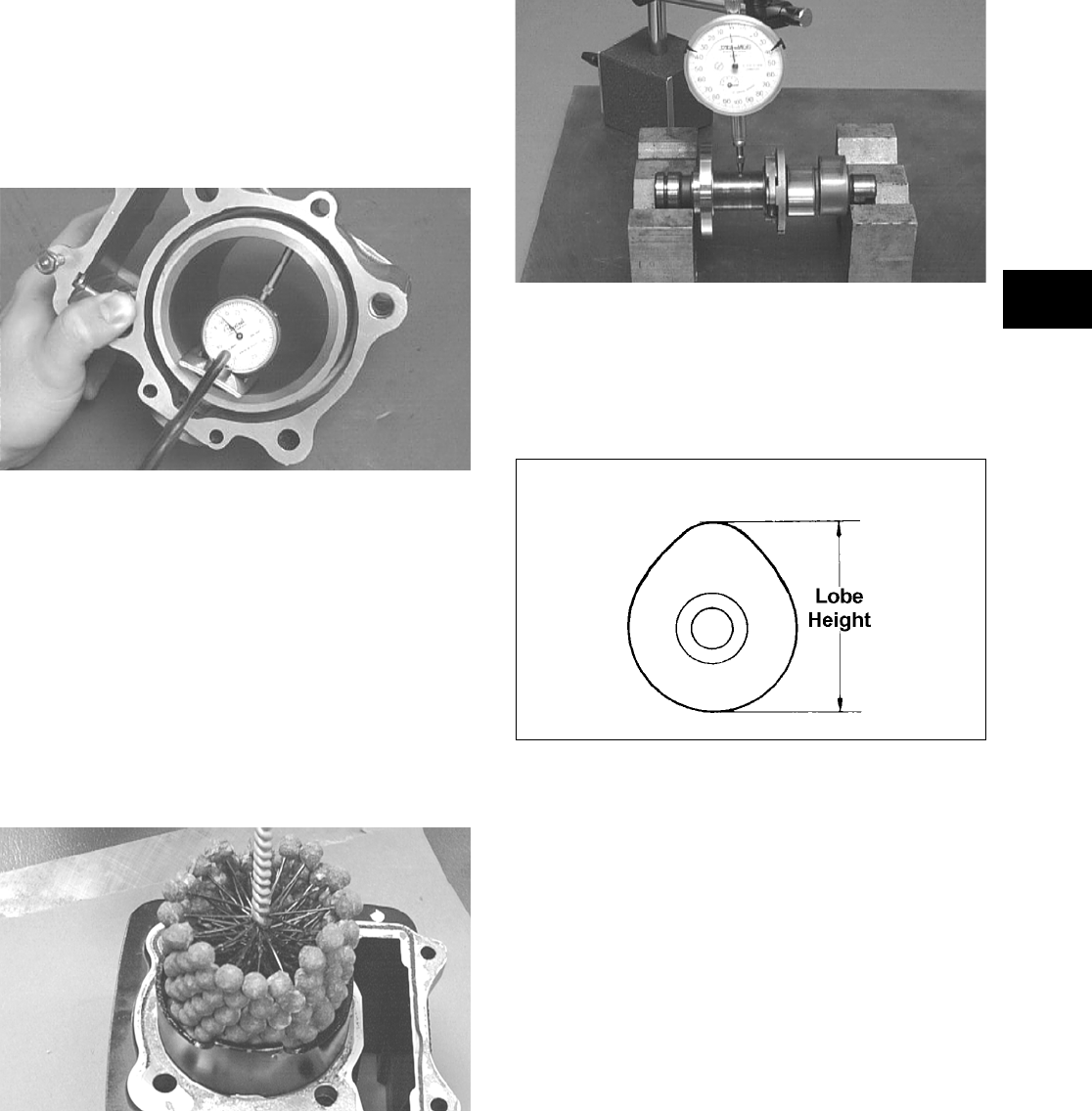
3-17
3
Inspecting Cam Chain Guide
1. Inspect cam chain guide for cuts, tears, breaks, or
chips.
2. If the chain guide is damaged, it must be replaced.
Honing Cylinder
1. Using a slide gauge and a dial indicator or a snap
gauge, measure the cylinder bore diameter in three
locations from top to bottom and again from top to
bottom at 90° from the first measurements for a
total of six measurements. The trueness
(out-of-roundness) is the difference between the
highest and lowest reading. Maximum trueness
(out-of-roundness) must not exceed specifications.
CC127D
2. Wash the cylinder in parts-cleaning solvent.
3. Inspect the cylinder for pitting, scoring, scuffing,
and corrosion. If marks are found, repair the sur—
face using a #320 grit ball hone.
NOTE: To produce the proper 60° cross-hatch
pattern, use a low RPM drill (600 RPM) at the rate
of 30 strokes per minute. If honing oil is not avail-
able, use a lightweight petroleum-based oil. Thor—
oughly clean cylinder after honing using soap and
hot water. Dry with compressed air; then immedi-
ately apply oil to the cylinder bore. If the bore is
severely damaged or gouged, replace the cylinder.
CC390D
4. If any measurement exceeds the limit, the cylinder
must be replaced.
Measuring Camshaft Runout
NOTE: If the camshaft is out of tolerance, it must
be replaced.
1. Place the camshaft on a set of V blocks; then posi-
tion the dial indicator contact point against the
shaft and zero the indicator.
CC283D
2. Rotate the camshaft and note runout; maximum
tolerance must not exceed specifications.
Measuring Camshaft Lobe Height
1. Using a calipers, measure each cam lobe height.
ATV1013A
2. The lobe heights must be greater than minimum
specifications.
Inspecting Camshaft Bearing
Journal
1. Inspect the bearing journal for scoring, seizure
marks, or pitting.
2. If excessive scoring, seizure marks, or pitting is
found, the cylinder head assembly must be
replaced.
Measuring Camshaft to
Cylinder Head Clearance
1. Loosen the jam nuts and adjuster screws.
FOR ARCTIC CAT ATV DISCOUNT PARTS CALL 606-678-9623 OR 606-561-4983
www.mymowerparts.com

3-18
CC005D
2. Place a strip of plasti-gauge in each of the cam-
shaft lands in the cylinder head.
3. Place the valve cover on the cylinder head and
secure with the valve cover cap screws. Tighten
securely.
NOTE: Do not rotate the camshaft when measur—
ing clearance.
4. Remove the cap screws securing the valve cover to
the cylinder; then remove the valve cover and
camshaft.
MD1261
5. Match the width of the plasti-gauge with the chart
found on the plasti-gauge packaging to determine
camshaft to cylinder head and valve cover clear-
ance.
CC145D
6. If clearance is excessive, measure the journals of
the camshaft.
CC287D
NOTE: If the journals are worn, replace the cam-
shaft; then measure the clearance again. If it is still
out of tolerance, replace the cylinder head.
Inspecting Camshaft Spring/Drive
Pin
1. Inspect the spring and unloader pin for damage.
CF061A
NOTE: With the weight extended, the unloader
pin should be flat-side out; with the weight
retracted, the unloader pin should be round-side
out.
CF060A
2. If damaged, the camshaft must be replaced.
FOR ARCTIC CAT ATV DISCOUNT PARTS CALL 606-678-9623 OR 606-561-4983
www.mymowerparts.com

3-19
3
Installing Top-Side
Components
A. Piston
B. Cylinder
1. Lubricate the piston pin, connecting rod, and pis-
ton pin bore with motor oil; then install the piston
on the connecting rod making sure there is a cir-
clip on each side.
FI626
NOTE: The piston should be installed so the IN
points towards the intake side.
2. Place the two alignment pins into position. Place a
new cylinder gasket into position; then place a pis-
ton holder (or suitable substitute) beneath the pis-
ton skirt and square the piston in respect to the
crankcase.
MD1344
3. Lubricate the inside wall of the cylinder; then
using a ring compressor or the fingers, compress
the rings and slide the cylinder over the piston.
Route the cam chain up through the cylinder cam
chain housing; then remove the piston holder and
seat the cylinder firmly on the crankcase.
GZ142
4. Loosely install the two nuts securing the cylinder
to the right-side crankcase half.
NOTE: The two cylinder-to-crankcase nuts will be
tightened in step 9.
FI622A
C. Cylinder Head/Camshaft
D. Cylinder Head Cover/
Rocker Arms
NOTE: Steps 1-4 in the preceding sub-section
must precede this procedure.
5. While keeping tension on the cam chain, place the
front cam chain guide into the cylinder.
CAUTION
The cylinder should slide on easily. Do not force the cyl-
inder or damage to the piston, rings, cylinder, or crank-
shaft assembly may occur.
CAUTION
Care should be taken that the bottom of the chain guide
is secured in the crankcase boss.
FOR ARCTIC CAT ATV DISCOUNT PARTS CALL 606-678-9623 OR 606-561-4983
www.mymowerparts.com

3-20
FI621
6. Place a new gasket into position on the cylinder.
Place the alignment pins into position; then place
the head assembly into position on the cylinder
making sure the cam chain is routed through the
chain cavity.
MD1347
7. Install the four cylinder head cap screws with
washers. Note that the two cap screws on the right
side of the cylinder head nearest the cam sprocket
are longer than the two cap screws on the left
(spark plug) side. Tighten only until snug.
8. Install the two lower nuts securing the cylinder
head to the cylinder, one in front and one in rear.
9. In a crisscross pattern, tighten the four cylinder
head cap screws (from step 7) to 28 ft-lb. Tighten
the two lower cylinder head nuts (from step  to
to
20 ft-lb and the cylinder-to-crankcase nuts (from
step 4) to 8 ft-lb.
10. With the timing inspection plug removed and the
cam chain held tight, rotate the crankshaft until the
piston is at top-dead-center.
11. While holding the cam chain to the front, install
the rear cam chain tensioner guide into the cylin-
der head. Install the pivot cap screw and washer.
Tighten to 11 ft-lb.
CD383
12. With the alignment pin installed in the camshaft
and the cam lobes directed down (toward the pis-
ton), place the camshaft in position and verify that
the timing mark on the magneto is visible through
the inspection plug and that the timing marks on
the camshaft sprocket are parallel with the valve
cover mating surface.
GZ190C
NOTE: When the camshaft assembly is seated,
make sure the alignment pin in the camshaft aligns
with the smallest hole in the sprocket.
13. With the alignment pin installed in the camshaft,
loosely place the cam sprocket (with the recessed
side facing the camshaft lobes) onto the camshaft
and place it into position with the cam chain over
the sprocket.
CD463
CAUTION
Keep tension on the cam chain to avoid damaging the
crankcase boss.
FOR ARCTIC CAT ATV DISCOUNT PARTS CALL 606-678-9623 OR 606-561-4983
www.mymowerparts.com

3-21
3
MD1359
14. Place the C-ring into position in its groove in the
cylinder head.
FI615
NOTE: At this point, oil the camshaft bearings,
cam lobes, and the three seating journals on the
cylinder head.
NOTE: Note the position of the alignment marks
on the end of the camshaft. They must be parallel
with the valve cover mating surface. If rotating the
camshaft and sprocket is necessary for alignment,
do not allow the crankshaft to rotate and be sure
the cam lobes end up in the down position.
15. When the camshaft assembly is seated, ensure the
following.
A. Piston still at top-dead-center.
B. Camshaft lobes directed down (toward the pis-
ton).
C. Camshaft alignment marks parallel to the valve
cover mating surface.
D. Recessed side of the sprocket directed toward
the cam lobes.
E. Camshaft alignment pin and sprocket alignment
hole (smallest) are aligned.
16. Place the tab washer onto the sprocket making
sure it covers the pin in the alignment hole.
MD1363
17. Apply red Loctite #271 to the first cap screw
securing the sprocket and tab washer to the cam—
shaft; then install the cap screw and tab washer.
Tighten cap screw only until snug.
CC404D
FI612
18. Rotate the crankshaft until the second cap screw
securing the sprocket to the camshaft can be
installed; then install the cap screw (threads coated
with red Loctite #271). Tighten to 11 ft-lb; then
bend the tab to secure the cap screw.
CAUTION
If any of the above factors are not as stated, go back to
step 13 and carefully proceed.
CAUTION
Care must be taken that the tab washer is installed cor-
rectly to cover the alignment hole on the sprocket. If the
alignment pin falls out, severe engine damage will
result.
FOR ARCTIC CAT ATV DISCOUNT PARTS CALL 606-678-9623 OR 606-561-4983
www.mymowerparts.com

3-22
19. Rotate the crankshaft until the first cap screw
(from step 17) securing the sprocket to the cam-
shaft can be addressed; then tighten to 11 ft-lb.
Bend the tab to secure the cap screw.
20. Install the cylinder head plug with the cupped end
facing the camshaft and the opening directed
downwards.
21. Place the cam chain tensioner assembly and gasket
into the cylinder. Tighten to 10 ft-lb.
22. Using a flat-blade screwdriver, turn the tensioner
screw counterclockwise to apply tension to the
cam chain; then install the cap screw plug and
washer and tighten securely.
FI608
23. Loosen the adjuster screw jam nuts; then loosen
the adjuster screws on the rocker arms in the valve
cover.
24. Apply a thin coat of Three Bond Sealant to the
mating surface of the valve cover; then place the
valve cover into position. Note that the two align-
ment pins are properly positioned.
NOTE: At this point, the rocker arms and adjuster
screws must not have pressure on them.
25. Install the four top-side cap screws with rubber
washers; then install the remaining cap screws.
Tighten only until snug.
MD1261
26. In a crisscross pattern starting from the center and
working outward, tighten the cap screws (from
step 25) to 8 ft-lb.
27. Adjust valve/tappet clearance (see Section 2).
28. Place the two tappet covers with O-rings into posi-
tion; then install and tighten the cap screws to 8
ft-lb.
FI602
29. Install the spark plug and tighten securely; then
install the timing inspection plug.
Left-Side Components
NOTE: For efficiency, it is preferable to remove
and disassemble only those components which
need to be addressed and to service only those
components. The technician should use discretion
and sound judgment.
NOTE: The engine/transmission does not have to
be removed from the frame for this procedure.
Removing Left-Side
Components
A. Water Pump
B. Speed Sensor
C. Magneto Cover/
Stator Assembly
1. Remove the coolant hose connecting the water
pump to the cylinder; then remove the water pump
cover.
AT THIS POINT
To service any one specific component, only limited dis-
assembly of components may be necessary. Note the
AT THIS POINT information in each sub-section.
FOR ARCTIC CAT ATV DISCOUNT PARTS CALL 606-678-9623 OR 606-561-4983
www.mymowerparts.com

3-23
3
FI538
2. Remove the water pump housing assembly noting
the location of the longer cap screw. Account for a
gasket and two alignment pins.
FI539
FI541
3. Remove two cap screws and the oil bolt securing
the oil pressure relief line to the engine. Account
for two crush washers and an O-ring.
FI544
4. Remove the water pump drive gear; then remove
the speed sensor housing assembly. Account for
two alignment pins, a gasket, and two seal wash-
ers.
FI543
5. Remove the cap screws securing the magneto
cover to the crankcase. Note the location of the two
internal cap screws and the two longer cap screws.
FI596A
6. Remove the magneto cover and account for two
alignment pins and the gasket.
D. Rotor/Flywheel
E. Starter Clutch/Gear
F. Starter Motor
NOTE: Steps 1-6 in the preceding sub-section
must precede this procedure.
7. Remove the nut securing the rotor/flywheel on the
crankshaft and install the crankshaft protector.
FI549
FOR ARCTIC CAT ATV DISCOUNT PARTS CALL 606-678-9623 OR 606-561-4983
www.mymowerparts.com

3-24
8. Using the Magneto Rotor Remover Set, break the
rotor/flywheel loose from the crankshaft; then
remove the puller and crankshaft protector and
remove the rotor/flywheel.
FI550
9. Remove the flywheel key from the crankshaft;
then remove the starter clutch gear.
FI551A
10. Remove starter idler gears and their respective
shafts; then remove the starter motor. Account for
an O-ring on the starter drive housing.
FI555
G. Shift Shaft
H. Drive Gear
NOTE: Steps 1-10 in the preceding sub-sections
must precede this procedure.
11. Remove the shift shaft noting a washer on each
end; then remove the cap screw securing the gear
shift cam plate and remove the plate from the shaft.
FI559
12. Remove the shift detent cam arm and spring.
FI560
13. Remove the snap ring securing the output drive
gear to the output shaft and remove the gear noting
that the hub flange is directed toward the crank-
case.
FI564
FI566
FOR ARCTIC CAT ATV DISCOUNT PARTS CALL 606-678-9623 OR 606-561-4983
www.mymowerparts.com

3-25
3
Servicing Left-Side
Components
INSPECTING STARTER
CLUTCH/GEAR
1. Place the starter clutch gear onto the rotor/fly-
wheel and attempt to rotate the starter clutch gear
clockwise. It should lock up to the rotor/flywheel.
Rotate the gear counterclockwise and it should
turn freely. If it moves or locks up both ways, the
starter clutch must be replaced.
2. Inspect the starter clutch gear for chipped or miss-
ing teeth or discoloration/scoring of the clutch sur—
face. Inspect the bearing for loose, worn, or
discolored rollers. If bearing is damaged, it must
be replaced.
FI569
3. Inspect the one-way bearing for chipped surfaces,
missing rollers, or discoloration. If any of the
above conditions exist, replace the starter clutch
assembly.
FI572
REPLACING STARTER CLUTCH
ASSEMBLY
1. Remove the cap screws securing the one-way
clutch assembly to the flywheel; then remove from
the flywheel.
FI570
2. Thoroughly clean the rotor/flywheel; then install
the new one-way clutch and secure with the cap
screws after applying a drop of red Loctite #271 to
the threads. Tighten to 26 ft-lb using a crisscross
pattern. Make sure the one-way bearing is installed
with the notches directed away from the rotor/fly-
wheel.
FI576A
FI578
REPLACING STARTER GEAR
BEARING
1. Support the starter clutch gear in a press making
sure to support the hub around the entire circum-
ference; then using a suitable bearing driver, press
the bearing from the gear.
FOR ARCTIC CAT ATV DISCOUNT PARTS CALL 606-678-9623 OR 606-561-4983
www.mymowerparts.com

3-26
FI583
2. Thoroughly clean the gear hub; then apply a drop
of green Loctite #620 to the bearing outer race and
press into the gear hub until even with the lower
chamfer radius.
FI580
INSPECTING STATOR/MAGNETO
COVER ASSEMBLY
1. Inspect the stator for burned or discolored wiring,
broken or missing hold-down clips, or loose cap
screws.
2. Inspect the bearings in the magneto housing for
discoloration, roughness when rotated, and secure
fit in bearing bores.
3. Inspect the oil pressure relief valve for evidence of
metal chips or contamination. Do not disassemble
the valve.
FI588
REPLACING STATOR COIL/
CRANKSHAFT POSITION SENSOR
1. Remove the three cap screws securing the stator
coil, two cap screws securing the crankshaft posi-
tion sensor, and one cap screw from the harness
hold-down.
2. Lift the rubber grommet out of the housing; then
remove the stator coil/crankshaft position sensor.
Account for and note the position of the harness
hold-down under the crankshaft position sensor.
FI590
3. Install the new stator coil assembly and secure
with three cap screws using a drop of red Loctite
#271 on each. Tighten to 8 ft-lb.
4. Place the stator wire harness hold-down into posi-
tion; then install the crankshaft position sensor and
secure with two cap screws. Tighten securely.
5. Install the upper cable hold-down and secure with
a cap screw. Tighten securely.
FI595A
REPLACING MAGNETO COVER
BEARINGS
1. Using a suitable press and proper support, press
the bearing from the housing as indicated (one
from outside and one from inside).
FOR ARCTIC CAT ATV DISCOUNT PARTS CALL 606-678-9623 OR 606-561-4983
www.mymowerparts.com

3-27
3
FI593
FI594
2. Clean the bearing bores in the housing and inspect
closely for cracks or shiny areas indicating bearing
movement. Replace the housing if any of the
above are evident.
3. With a drop of red Loctite #271 around the bearing
bore, press a new bearing into the magneto cover
until the bearing is firmly seated in the bearing
bore.
Installing Left-Side
Components
A. Starter Clutch/Gear
B. Rotor/Flywheel
1. If removed, place the crankshaft bearing retainer
into position. Apply red Loctite #271 to the three
cap screws. Install and tighten the three cap screws
securely.
MD1122
2. Install the starter motor and tighten the two cap
screws securely.
3. Install the shift detent cam making sure the washer
is installed.
MD1086
4. Install the shift detent cam arm and spring.
5. Install the gear shift shaft assembly and washer
making sure to align the alignment marks.
FI559
6. Install starter idler gears (1) and (2).
FOR ARCTIC CAT ATV DISCOUNT PARTS CALL 606-678-9623 OR 606-561-4983
www.mymowerparts.com

3-28
FI555A
7. Install the starter clutch gear onto the crankshaft;
then install the rotor/flywheel key in the crank-
shaft.
FI551A
8. Install the rotor/flywheel and secure with the nut.
Tighten to 107 ft-lb.
C. Magneto Cover
D. Water Pump
NOTE: Steps 1-8 in the preceding sub-section
must precede this procedure.
9. Install two alignment pins and place the magneto
cover gasket into position. Install the magneto
cover. Noting the different-lengthed 6 mm cap
screws and the location of the two internal cap
screws, tighten cap screws in a crisscross pattern
to 8 ft-lb.
FI596A
10. Install the water pump drive gear and secure with
the nut. Tighten to 28 ft-lb.
FI547
11. Install two alignment pins and a gasket on the
magneto cover; then install the water pump hous-
ing assembly. Tighten the cap screws to 8 ft-lb.
FI541A
FI539
12. Install the water pump cover with a new O-ring
and secure with the four cap screws. Tighten to 8
ft-lb.
FI538
FOR ARCTIC CAT ATV DISCOUNT PARTS CALL 606-678-9623 OR 606-561-4983
www.mymowerparts.com

3-29
3
13. Connect the coolant hoses to the water pump and
secure with the hose clamps. Tighten securely.
Right-Side Components
NOTE: For efficiency, it is preferable to remove
and disassemble only those components which
need to be addressed and to service only those
components. The technician should use discretion
and sound judgment.
NOTE: The engine/transmission does not have to
be removed from the frame for this procedure.
Removing Right-Side
Components
A. V-Belt Cover
B. Driven Pulley
C. Clutch Cover
1. If the engine is still in the frame, remove the cap
screw securing the brake pedal to the pivot shaft.
Account for a flat washer.
KC149A
2. Remove the cap screws securing the V—belt cover
to the clutch cover; then slide the brake pedal out-
ward and remove the V-belt cover. Account for
two alignment pins and a gasket.
KC142A
3. Mark the movable drive face and the fixed drive
face for installing purposes; then remove the nut
holding the movable drive face onto the crankshaft.
MD1033
4. Remove the movable drive face and spacer.
Account for the movable drive face rollers and
outer drive face cover.
MD1035
MD1034
AT THIS POINT
To service center crankcase components only, proceed
to Removing Right-Side Components.
AT THIS POINT
To service any one specific component, only limited dis-
assembly of components may be necessary. Note the
AT THIS POINT information in each sub-section.
FOR ARCTIC CAT ATV DISCOUNT PARTS CALL 606-678-9623 OR 606-561-4983
www.mymowerparts.com

3-30
MD1036
5. Using a 6 mm cap screw threaded into the fixed
driven face, spread the driven pulley by turning the
cap screw clockwise; then remove the V-belt.
KC132
6. Remove the fixed drive face.
MD1094
7. Remove the nut holding the driven pulley assem-
bly; then remove the driven pulley assembly.
MD1068
8. Using an impact screwdriver, remove the three
Phillips-head cap screws holding the air intake
plate. Remove the air intake plate.
MD1092
9. Remove the cap screws holding the clutch cover
onto the right-side crankcase half. Note the posi-
tions of the different-lengthed cap screws for
installing purposes.
10. Using a rubber mallet, loosen the clutch cover;
then pull it away from the right-side crankcase
half. Account for two alignment pins and gasket.
MD1115
D. Centrifugal Clutch Assembly
E. Oil Pump Drive Gear
F. Oil Pump Driven Gear
NOTE: Steps 1-10 in the preceding sub-section
must precede this procedure.
FOR ARCTIC CAT ATV DISCOUNT PARTS CALL 606-678-9623 OR 606-561-4983
www.mymowerparts.com

3-31
3
11. Remove the one-way clutch noting the direction of
the green dot or the word OUTSIDE for installing
purposes.
MD1286
12. Remove the left-hand threaded nut holding the
centrifugal clutch assembly.
MD1014
MD1016
13. Remove the cam chain.
FI630
14. Remove the oil pump drive gear cap screw.
MD1018
15. Remove oil pump drive gear. Account for the pin.
MD1017
16. Remove the snap ring holding the oil pump driven
gear.
MD1019
CAUTION
Care must be taken when removing the nut; it has
“left-hand” threads.
FOR ARCTIC CAT ATV DISCOUNT PARTS CALL 606-678-9623 OR 606-561-4983
www.mymowerparts.com

3-32
NOTE: Always use a new snap ring when install-
ing the oil pump driven gear.
17. Remove oil pump driven gear. Account for the
drive pin and thrust washer.
MD1020
G. Oil Pump/Oil Strainer
NOTE: Steps 1-17 in the preceding sub-sections
must precede this procedure.
18. Remove three cap screws holding the oil pump
and remove the oil pump. Account for two align-
ment pins.
MD1060
19. Remove the four cap screws securing the oil
strainer cap; then remove the Phillips-head screws
securing the oil strainer. Account for the O-ring.
MD1337
MD1208
Servicing Right-Side
Components
NOTE: Whenever a part is worn excessively,
cracked, damaged in any way, or out of tolerance,
replacement is necessary.
INSPECTING CENTRIFUGAL
CLUTCH SHOE
1. Inspect the clutch shoe for uneven wear, chips,
cracks, or discoloration.
2. Inspect the depth of the grooves in the clutch
shoes. If any shoe is worn to the bottom of the
groove, replace the complete set.
AT THIS POINT
To service clutch components, see Servicing Right-Side
Components sub-section.
AT THIS POINT
To service center crankcase components only, proceed
to Separating Crankcase Halves.
CAUTION
Always replace clutch shoes as a complete set or
severe imbalance could occur.
FOR ARCTIC CAT ATV DISCOUNT PARTS CALL 606-678-9623 OR 606-561-4983
www.mymowerparts.com

3-33
3
ATV1014
INSPECTING CENTRIFUGAL
CLUTCH HOUSING
1. Inspect the clutch housing for burns, marks, scuffs,
cracks, scratches, or uneven wear.
2. If the housing is damaged in any way, the housing
must be replaced.
INSPECTING PRIMARY
ONE-WAY DRIVE
1. Place the one-way clutch onto the clutch shoe
assembly with the green dot or the word “OUT—
SIDE” directed away from the clutch shoe.
KC330
2. Place the clutch housing onto the clutch
shoe/one-way clutch.
NOTE: It will be necessary to rotate the clutch
housing counterclockwise to properly seat the
one-way clutch.
KC331A
3. Check that the clutch shoe can only be rotated
counterclockwise in respect to the clutch housing.
If the clutch shoe locks up or turns in both direc-
tions, the one-way clutch must be replaced.
KC332A
INSPECTING OIL PUMP
1. Inspect the pump for damage.
2. It is inadvisable to remove the screw securing the
pump halves. If the oil pump is damaged, it must
be replaced.
NOTE: The oil pump is a non-serviceable compo-
nent and must be replaced as a complete assem-
bly.
DRIVEN PULLEY ASSEMBLY
NOTE: The driven pulley assembly is a non-ser-
viceable component and must be replaced as a
complete assembly.
Installing Right-Side
Components
A. Oil Strainer/Oil Pump
1. Place the oil strainer into position beneath the
crankcase. Tighten the Phillips-head screws
securely.
MD1337
FOR ARCTIC CAT ATV DISCOUNT PARTS CALL 606-678-9623 OR 606-561-4983
www.mymowerparts.com

3-34
2. Place the strainer cap into position on the crank-
case making sure the O-ring is properly installed
and secure with the four cap screws; then tighten
the oil drain plug to 16 ft-lb.
MD1208
3. Place two alignment pins and the oil pump into
position on the crankcase and secure with the Phil-
lips-head screws coated with red Loctite #271.
Tighten to 8 ft-lb.
MD1060
4. Place the thrust washer and drive pin into position
on the oil pump shaft, install the oil pump driven
gear making sure the recessed side of the gear is
directed inward, and secure with a new snap ring.
NOTE: Always use a new snap ring when install-
ing the oil pump driven gear.
MD1020
MD1019
5. Install the cam chain.
NOTE: Keep tension on the cam chain to avoid
damaging the crankcase boss.
6. Place the pin into position, install the oil pump
drive gear, and tighten the cap screw (coated with
red Loctite #271) to 63 ft-lb.
MD1017
MD1018
7. Install the clutch shoe assembly on the crankshaft;
then install the flange nut (left-hand thread)
(coated with red Loctite #271). Tighten to 147
ft-lb.
NOTE: The flat side of the flange nut should be
directed towards the clutch shoe.
CAUTION
Care must be taken when installing the flange nut; it has
“left-hand” threads.
FOR ARCTIC CAT ATV DISCOUNT PARTS CALL 606-678-9623 OR 606-561-4983
www.mymowerparts.com

3-35
3
8. Install the one-way clutch making sure that the
green dot or the word OUTSIDE is directed away
from the crankcase.
MD1286
B. Clutch Cover
C. Fixed Drive Face
D. Movable Drive Face
NOTE: Steps 1-8 in the preceding sub-section
must precede this procedure.
9. Install two alignment pins and place the clutch
cover gasket into position. Install the clutch cover.
MD1115
10. Tighten the clutch cover cap screws to 8 ft-lb.
MD1117
11. Install the air intake plate. Apply red Loctite #271
to the threads of the three Phillips-head cap
screws; then install and tighten securely.
MD1342
12. Place the driven pulley assembly into position and
secure with the nut (threads coated with red Loc-
tite #271). Tighten to 147 ft-lb.
MD1068
KC134
13. Slide the fixed drive face assembly onto the front
shaft.
14. Spread the faces of the driven pulley by threading
a V—belt cover cap screw into the fixed driven face
and tightening until the faces open sufficiently to
allow the V-belt to drop into the pulley approxi-
mately 3/4 in.
FOR ARCTIC CAT ATV DISCOUNT PARTS CALL 606-678-9623 OR 606-561-4983
www.mymowerparts.com

3-36
KC137
NOTE: The arrows on the V-belt should point in
direction of engine rotation.
15. Making sure the movable drive face rollers are in
position, pinch the V-belt together near its center
and slide the spacer and movable drive face onto
the shaft.
KC127
16. Coat the threads of the nut with red Loctite #271;
then making sure the splines of the clutch shaft
protrude through the cover plate, secure with the
nut and tighten to 147 ft-lb.
KC138
KC141
NOTE: At this point, the cap screw can be
removed from the driven pulley face.
17. Rotate the V-belt and drive/driven assemblies until
the V-belt is flush with the top of the driven pulley.
18. Install two alignment pins and place a new V-belt
cover gasket into position on the clutch cover. In a
crisscross pattern, tighten cap screws to 8 ft-lb.
KC142A
Center Crankcase
Components
NOTE: This procedure cannot be done with the
engine/transmission in the frame. Complete
Removing procedures for Top-Side, Left-Side, and
Right-Side must precede this procedure.
NOTE: For efficiency, it is preferable to remove
and disassemble only those components which
need to be addressed and to service only those
components. The technician should use discretion
and sound judgment.
FOR ARCTIC CAT ATV DISCOUNT PARTS CALL 606-678-9623 OR 606-561-4983
www.mymowerparts.com

3-37
3
Separating Crankcase
Halves
1. Remove the left-side and right-side cap screws
securing the crankcase halves noting the position
of the different-sized cap screws for joining pur—
poses.
MD1006
MD1012
2. Using Crankcase Separator/Crankshaft Remover
and tapping lightly with a rubber mallet, separate
the crankcase halves. Account for two alignment
pins.
CC869
NOTE: To keep the shaft/gear assemblies intact
for identification, tap the shafts toward the
left-side crankcase half when separating the
halves.
MD1313
Disassembling
Crankcase Half
NOTE: To aid in installing, it is recommended that
the assemblies be kept together and in order.
NOTE: For steps 1-6, refer to illustration FI639A.
FI639A
1. Remove the secondary driven shaft assembly (A)
noting the location of the front and rear bearing
locating pins and the center bearing locating ring.
FI660A
FOR ARCTIC CAT ATV DISCOUNT PARTS CALL 606-678-9623 OR 606-561-4983
www.mymowerparts.com

3-38
FI659A
FI661A
2. Remove the reverse idler assembly (B). Account
for and note the location of the inner bushing (1),
idler shaft (2), and outer washer (3).
FI641A
3. Remove the driveshaft (C); then pull the shift fork
locating shaft (D) out of the crankcase locating
boss and allow the shift forks to disengage from
the gear shift shaft (F).
FI646
FI653A
4. Remove the gear shift shaft (F) noting the inner
and outer washers.
FI650A
5. Remove the countershaft assembly (E) along with
the shift fork assembly.
FI662
FOR ARCTIC CAT ATV DISCOUNT PARTS CALL 606-678-9623 OR 606-561-4983
www.mymowerparts.com

3-39
3
6. Remove the crank balancer driven gear (G) and
account for a key; then remove the crankshaft bal-
ancer shaft.
MD1024
7. Using Crankcase Separator/Crankshaft Remover
with the appropriate crankshaft protector, remove
the crankshaft.
MD1330
8. Remove the secondary drive gear/secondary
driven gear retaining nut. From inside the crank-
case using a rubber mallet, drive out the output
shaft assembly. Account for the output shaft, a
shim, a washer, and the nut.
Servicing Center
Crankcase Components
NOTE: Whenever a part is worn excessively,
cracked, damaged in any way, or out of tolerance,
replacement is necessary.
SECONDARY GEARS
NOTE: When checking and correcting secondary
gear backlash and tooth contact, the universal
joint must be secured to the front shaft or false
measurements will occur.
Checking Backlash
NOTE: The rear shaft and bevel gear must be
removed for this procedure. Also, always start with
the original shims on the rear shaft.
1. Place the left-side crankcase cover onto the
left-side crankcase half to prevent runout of the
secondary transmission output shaft.
2. Install the secondary driven output shaft assembly
onto the crankcase.
3. Mount the indicator tip of the dial indicator on the
secondary driven bevel gear (centered on the gear
tooth).
4. While rocking the driven bevel gear back and
forth, note the maximum backlash reading on the
gauge.
5. Acceptable backlash range is 0.05-0.33 mm
(0.002-0.013 in.).
Correcting Backlash
NOTE: If backlash measurement is within the
acceptable range, no correction is necessary.
1. If backlash measurement is less than specified,
remove an existing shim, measure it, and install a
new thinner shim.
2. If backlash measurement is more than specified,
remove an existing shim, measure it, and install a
thicker shim.
NOTE: Continue to remove, measure, and install
until backlash measurement is within tolerance.
Note the following chart.
Checking Tooth Contact
NOTE: After correcting backlash of the second-
ary driven bevel gear, it is necessary to check
tooth contact.
1. Remove the secondary driven output shaft assem-
bly from the left-side crankcase half.
CAUTION
Do not remove the remaining output shaft assembly
unless absolutely necessary. If the shaft is removed, the
shaft nut must be replaced with a new one and the shaft
must be re-shimmed.
AT THIS POINT
To service crankshaft assembly, see Servicing Center
Crankcase Components sub-section.
Backlash Measurement Shim Correction
Under 0.05 mm (0.002 in.) Decrease Shim
Thickness
At 0.05-0.33 mm
(0.002-0.013 in.)
No Correction Required
Over 0.33 mm (0.013 in.) Increase Shim
Thickness
FOR ARCTIC CAT ATV DISCOUNT PARTS CALL 606-678-9623 OR 606-561-4983
www.mymowerparts.com

3-40
2. Clean the secondary driven bevel gear teeth of old
oil and grease residue.
3. Apply a thin, even coat of a machinist-layout dye
to several teeth of the gear.
4. Install the secondary driven output shaft assembly.
5. Rotate the secondary driven bevel gear several
revolutions in both directions.
6. Examine the tooth contact pattern in the dye and
compare the pattern to the illustrations.
ATV-0103
ATV-0105
ATV-0104
Correcting Tooth Contact
NOTE: If tooth contact pattern is comparable to
the correct pattern illustration, no correction is
necessary.
If tooth contact pattern is comparable to an incorrect
pattern, correct tooth contact according to the follow-
ing chart.
NOTE: To correct tooth contact, steps 1 and 2
(with NOTE) of “Correcting Backlash” must be fol-
lowed and the above “Tooth Contact/Shim Correc-
tion” chart must be consulted.
CRANKSHAFT ASSEMBLY
NOTE: The crankshaft and connecting rod is a
non-serviceable assembly. If any component is
out of specification, the assembly must be
replaced.
Measuring Connecting Rod
(Small End Inside Diameter)
1. Insert a snap gauge into the upper connecting rod
small end bore; then remove the gauge and mea-
sure it with micrometer.
CC290D
2. Maximum diameter must not exceed specifica-
tions.
Measuring Connecting Rod
(Small End Deflection)
1. Place the crankshaft on a set of V-blocks and
mount a dial indicator and base on the surface
plate. Position the indicator contact point against
the center of the connecting rod small end journal.
2. Zero the indicator and push the small end of the
connecting rod away from the dial indicator.
3. Maximum deflection must not exceed specifica-
tions.
Tooth Contact Shim Correction
Contacts at Top Decrease Shim Thickness
Contacts at Root Increase Shim Thickness
CAUTION
After correcting tooth contact, backlash must again be
checked and corrected (if necessary). Continue the cor—
recting backlash/correcting tooth contact procedures
until they are both within tolerance values.
FOR ARCTIC CAT ATV DISCOUNT PARTS CALL 606-678-9623 OR 606-561-4983
www.mymowerparts.com

3-41
3
Measuring Connecting Rod
(Big End Side-to-Side)
1. Push the lower end of the connecting rod to one
side of the crankshaft journal.
2. Using a feeler gauge, measure the gap between the
connecting rod and crankshaft journal.
CC289D
3. Acceptable gap range must be within specifica-
tions.
Measuring Crankshaft (Runout)
1. Place the crankshaft on a set of V blocks.
2. Mount a dial indicator and base on the surface
plate. Position the indicator contact at point 1 of
the crankshaft.
ATV-1074
3. Zero the indicator and rotate the crankshaft slowly.
4. Maximum runout must not exceed specifications.
NOTE: Proceed to check runout on the other end
of the crankshaft by positioning the indicator con—
tact at point 2 and following steps 3-4.
Measuring Crankshaft
(Web-to-Web)
1. Using a calipers, measure the distance from the
outside edge of one web to the outside edge of the
other web.
ATV-1017
2. Acceptable width range must be within specifica-
tions.
COUNTERSHAFT
Disassembling
1. Remove the reverse driven gear dog; then remove
the circlip securing the reverse driven gear.
FI663
CAUTION
Care should be taken to support the connecting rod
when rotating the crankshaft.
CAUTION
When disassembling the countershaft, care must be
taken to note the direction each major component (dog,
gear) faces. If a major component is installed facing the
wrong direction, transmission damage may occur
and/or the transmission will malfunction. In either case,
complete disassembly and assembly will be required.
FOR ARCTIC CAT ATV DISCOUNT PARTS CALL 606-678-9623 OR 606-561-4983
www.mymowerparts.com

3-42
FI664
2. Remove the splined washer; then remove the
reverse driven gear along with the bearing and
bushing.
FI665
3. Remove the low driven gear washer; then remove
the low driven gear along with the bearing and
bushing.
FI666
FI667
4. Remove the splined washer; then remove the cir-
clip securing the high-low sliding dog. Remove
the sliding dog.
FI668
FI669
5. Remove the circlip securing the high driven gear;
then remove a washer, the high driven gear along
with the bearing and bushing, and remove the high
driven washer.
FI670
FI671
FOR ARCTIC CAT ATV DISCOUNT PARTS CALL 606-678-9623 OR 606-561-4983
www.mymowerparts.com

3-43
3
ASSEMBLING
1. With the high driven washer (1) on the counter-
shaft, install the high driven gear bushing (3),
bearings (2), and gear (4) on the countershaft; then
install the washers (5) and secure with the
snap-ring.
FI671A
FI670
2. Install the high/low shift dog (6) on the counter-
shaft and secure with snap-ring (7); then install the
splined washer (8).
FI668A
3. Install the low driven bushing (10), bearing (9),
and gear (11) on the countershaft; then install
splined washer (12).
FI667A
FI666
4. Place the reverse driven bushing (13) onto the
shaft; then install the bearing (14), gear (15), and
splined washer (16). Secure with a snap-ring.
FI665A
FI664
5. Install the reverse dog on the shaft; then place the
shift forks and shift shaft into position.
FOR ARCTIC CAT ATV DISCOUNT PARTS CALL 606-678-9623 OR 606-561-4983
www.mymowerparts.com

3-44
FI663
FI662
NOTE: The countershaft assembly is now ready
to be installed.
Assembling Crankcase
Half
NOTE: For ease of assembly, install components
on the right-side crankcase half.
NOTE: If the output shaft was removed, make
sure that the proper shim is installed.
1. Install the output shaft into the crankcase making
sure the two gears, shim, washer, and nut are in the
correct order.
MD1199
MD1079
2. Install and tighten the output shaft flange nut to 59
ft-lb. Using a punch, peen the nut.
MD1333
3. Apply a liberal amount of oil to the crankshaft
bearing. Using a propane torch, heat the bearing
until the oil begins to smoke; then slide the crank-
shaft assembly into place.
MD1334
NOTE: If heating the bearing is not possible, the
crankshaft can be installed using a crankshaft
installer.
4. Rotate the crankshaft so the counterweight is
toward the rear of the engine. Install the crank bal-
ancer shaft.
FOR ARCTIC CAT ATV DISCOUNT PARTS CALL 606-678-9623 OR 606-561-4983
www.mymowerparts.com

3-45
3
MD1024
5. Install the key in the crank balancer shaft; then
install the gear and aligning the timing marks,
slide the gear into place.
FI658
6. Align the shift cam fork slots with the shift fork
shaft locating boss and with a washer on each end,
install in the crankcase.
FI652A
7. Place the shift forks into position on the assembled
countershaft and install into the crankshaft as an
assembly.
FI662
FI653
8. Align the shift forks to allow engagement with the
shift cam; then engage the shift forks and slide the
shift fork shaft into the locating boss in the crankcase.
FI653A
FI655A
9. Install the input driveshaft.
FOR ARCTIC CAT ATV DISCOUNT PARTS CALL 606-678-9623 OR 606-561-4983
www.mymowerparts.com

3-46
FI646
10. Install the spacer (1), shaft (2), reverse idler gear,
and washer (3).
FI641A
FI645
11. Install the secondary output driveshaft assembly
into the crankcase half making sure the front and
rear bearing alignment pins are seated in the
recesses; then install the center carrier bearing
alignment C-ring.
FI660A
FI659A
FI661A
Joining Crankcase
Halves
1. Verify that the two alignment pins (A) are in place
and that both case halves are clean and grease free.
Apply Three Bond Sealant to the mating surfaces.
Place the right-side half onto the left-side half.
FOR ARCTIC CAT ATV DISCOUNT PARTS CALL 606-678-9623 OR 606-561-4983
www.mymowerparts.com

3-47
3
FI639B
NOTE: Be sure to apply sealant to the inside
radius of all cap screw locations and the entire
surface of the internal cap screw bosses.
FI639C
2. Using a plastic mallet, lightly tap the case halves
together until cap screws can be installed.
3. From the right side, install the crankcase cap
screws noting the location of the different-sized
cap screws; then tighten only until snug.
NOTE: Rotate the shafts back and forth to ensure
no binding or sticking occurs while tightening the
cap screws.
MD1008
4. From the left side, install the remaining crankcase
cap screws; then tighten only until snug.
NOTE: Rotate the shafts back and forth to ensure
no binding or sticking occurs while tightening the
cap screws.
CC871
5. In a crisscross pattern, tighten the 8 mm cap
screws until the halves are correctly joined; then
tighten to 21 ft-lb.
NOTE: Rotate the shafts back and forth to ensure
no binding or sticking occurs.
6. In a crisscross pattern, tighten the 6 mm cap
screws to 10 ft-lb.
NOTE: Rotate the shafts back and forth to ensure
no binding or sticking occurs.
Installing
Engine/Transmission
1. From the left side, place the engine into the frame
(rear of engine first) tilting the rear up to allow
cylinder head to clear frame.
2. With engine moved rearward, engage the splines
of the front driveline into the front output drive
yoke; then move into position and install the two
through-bolts. Secure with lock nuts and tighten to
35 ft-lb.
3. Install the four cap screws securing the rear driveline
to the output drive flange and tighten to 20 ft-lb.
4. Connect coolant hoses (A) and (B) to the water
pump and connect the upper coolant hose to the
thermostat housing. Tighten all clamps securely.
AT THIS POINT
After completing center crankcase components, pro-
ceed to Installing Right-Side Components, to Installing
Left-Side Components, and to Installing Top-Side Com-
ponents.
FOR ARCTIC CAT ATV DISCOUNT PARTS CALL 606-678-9623 OR 606-561-4983
www.mymowerparts.com

3-48
FI530B
FI537
5. Install the exhaust pipe using a new seal at the cyl-
inder head and loosely install the retaining cap
screws; then install the muffler with a new grafoil
seal and secure with two springs. Tighten the
exhaust pipe retainer cap screws to 20 ft-lb.
6. Connect the throttle cable and adjust free-play to
specifications (see Section 4); then tighten the
jam-nut securely and install the cover. Tighten the
screws securely.
7. Connect the stator connector (H) and crankshaft
position sensor connector (I) to the main harness;
then connect the positive cable to the starter motor
and tighten securely.
FI534A
8. Connect the engine ground cable to the starter
mounting flange and secure with a cap screw tight-
ened to 8 ft-lb.
9. From the top side, install the ECT sensor connec-
tor (C), fuel injector connector (D), MAP/IAT sen-
sor connector (E), ISC connector (F), and the TPS
connector (G).
FI522A
10. Place the air filter assembly into position and con-
nect the crankcase breather securing with the
clamp; then connect the front air inlet duct and
secure with a hose clamp.
11. Install the harness connector onto the coil and
install the spark plug cap.
12. Connect the air ducts to the CVT housing and
tighten the clamps securely; then connect the air
duct to the air filter housing and the throttle body
and secure with the clamps.
13. Install the storage compartment and connect the
negative battery cable; then install the tool tray.
14. Pour the specified amount of coolant into the radi-
ator and the specified amount and grade of oil into
the engine.
15. Install the left footwell support assembly, footwell,
and footrest. Tighten all fasteners securely.
16. Install the seat making sure it locks securely in
place; then start the engine and allow to warm up
while checking for leaks.
17. Shut engine off and inspect coolant and oil levels.
Add fluids as required.
FOR ARCTIC CAT ATV DISCOUNT PARTS CALL 606-678-9623 OR 606-561-4983
www.mymowerparts.com

3-49
3
Table of Contents (1000)
Removing Engine/ Transmission………………….….. 3-49
Top-Side Components……………….…………….…….. 3-53
Removing Top-Side Components ……………..…….. 3-53
Servicing Top-Side Components……………………... 3-57
Installing Top-Side Components ………………….….. 3-64
Left-Side Components ………..……………..………….. 3-71
Removing Left-Side Components …….……………... 3-71
Installing Left-Side Components …………….……….. 3-73
Right-Side Components …………….…………….…….. 3-76
Removing Right-Side Components………………….. 3-76
Servicing Right-Side Components …………………… 3-78
Installing Right-Side Components…….……………... 3-78
Center Crankcase Components……….……………... 3-80
Separating Crankcase Halves……………..………….. 3-81
Disassembling Crankcase Half ..…………….……….. 3-82
Servicing Center Crankcase Components.……….. 3-83
Assembling Crankcase Half ……………………..…….. 3-91
Joining Crankcase Halves……………….……………... 3-93
Installing Engine/Transmission…………….………….. 3-94
Removing Engine/
Transmission
Many service procedures can be performed without
removing the engine/transmission from the frame.
Closely observe the note introducing each sub-section for
this important information.
Secure the ATV on a support stand to elevate the wheels.
1. Remove the seat and tool tray; then remove the nega-
tive battery cable.
2. Remove the front rack, gauge pod, footwells and
footrests; then remove the front body panel (see Sec-
tion 8).
3. Disconnect the IAT sensor connector; then loosen the
clamp securing the inlet air boot to the throttle body
and remove the air filter housing assembly.
GZ013
GZ091A
4. Using an absorbent towel, clean any spilled gasoline;
then press the gasline hose connectors and remove
from the fuel rails.
GZ124
5. Disconnect the TPS connector (A), MAP sensor con-
nector (B), and ISC valve connector (C) from the
throttle body; then route the harness and connectors
away from the engine.
AT THIS POINT
If the technician’s objective is to service front Top-Side
Components, Left-Side Components, or Right-Side
Components, the engine/transmission does not have to
be removed from the frame.
AT THIS POINT
If the technician’s objective is to service/replace the oil
strainer (from beneath the engine/transmission), the
engine/transmission does not have to be removed from
the frame.
! WARNING
Make sure the ATV is solidly supported on the support
stand to avoid injury.
FOR ARCTIC CAT ATV DISCOUNT PARTS CALL 606-678-9623 OR 606-561-4983
www.mymowerparts.com

3-50
GZ094A
NOTE: Using a suitable marker, mark the locations
of any ties that are removed to relocate wiring out of
the way.
6. Loosen the clamps securing the throttle body to the
intake manifolds; then remove the throttle body and
leaving the throttle cable connected, lay the assem-
bly over the handlebar.
GZ090B
7. Disconnect the fuel injector wiring connectors; then
remove the intake manifolds leaving the injectors
installed.
GZ106
GZ107
8. Disconnect the stator coil connector and the crankshaft
position sensor connector; then disconnect the gear posi-
tion switch connector from the gear position switch.
GZ069A
GZ493A
9. Loosen the clamps securing the V-belt cooling ducts
to the V-belt housing; then disconnect the cooling
ducts.
GZ037
FOR ARCTIC CAT ATV DISCOUNT PARTS CALL 606-678-9623 OR 606-561-4983
www.mymowerparts.com

3-51
3
GZ103B
10. Remove the E-clips securing the shift linkage to the
shift lever and shift shaft; then remove the shift link-
age. Account for two bushings and two flat washers.
11. Remove the cap screws securing the rear driveshaft
yoke flange to the rear output flange.
GZ374
12. Remove the exhaust pipe springs at the muffler and
remove the muffler. Account for the grafoil seal.
GZ372
13. Remove the nuts securing the rear exhaust pipe to the
cylinder; then remove the springs securing the rear
exhaust pipe to the front exhaust pipe and remove the
rear exhaust pipe. Account for a grafoil seal on the
pipe juncture and a seal in the cylinder.
GZ099A
14. Remove the front and rear spark plug wires from the
spark plugs; then disconnect the primary wire con-
nectors from the coils and remove the coils from the
left side of the frame.
GZ071A
15. Remove the cap screw securing the engine and har—
ness grounds to the engine.
GZ064A
16. Remove the cap screws securing the upper bumper
support to the frame and swing the bumper forward
allowing access to the radiator drain plug.
FOR ARCTIC CAT ATV DISCOUNT PARTS CALL 606-678-9623 OR 606-561-4983
www.mymowerparts.com

3-52
GZ068
17. Place a suitable drain pan under the radiator; then
remove the radiator drain plug. Do not loosen the
radiator cap at this time.
GZ086A
18. Remove the bleed screw from the water pump; then
after coolant has drained, apply compressed air to the
bleed opening to purge the remaining coolant from
the system. Install the bleed screw and radiator drain
plug and tighten securely.
GZ009A
19. Remove the coolant hoses from the upper engine
coolant outlet pipes; then remove the lower coolant
hose from the water pump.
GZ028
GZ369A
GZ008
20. Remove the flange nuts from the front and rear
engine through-bolts; then rock the engine slightly to
relieve engine mount pressure and remove the
through-bolts.
GZ118
! WARNING
Always wear safety glasses when using compressed
air.
FOR ARCTIC CAT ATV DISCOUNT PARTS CALL 606-678-9623 OR 606-561-4983
www.mymowerparts.com

3-53
3
GZ104
21. Rotate the front driveshaft until the output yoke uni-
versal joint is in the vertical plane; then raise the
front of the engine/transmission until the front drive
splines disengage from the differential.
GZ 110A
GZ117A
22. Fold the front drive line up and secure against the front
of the engine; then lift the engine clear of the mount-
ings and remove from the right side of the frame.
GZ123
Top-Side Components
NOTE: For efficiency, it is preferable to remove and
disassemble only those components which need to
be addressed and to service only those components.
The technician should use discretion and sound
judgment.
NOTE: The engine/transmission must be removed
to service the rear cylinder head, cylinder, and piston.
Removing Top-Side
Components
A. Valve Cover/Rocker Arms
B. Cylinder Head/Camshaft
1. Remove the timing inspection plug, spark plugs, and
magneto housing cover; then install the 10 mm cap
screw (left-hand threads) in the crankshaft and rotate
the desired cylinder to top-dead-center of the com-
pression stroke.
GZ027
GZ026
AT THIS POINT
To service any one specific component, only limited dis-
assembly of components may be necessary. Note the
AT THIS POINT information in each sub-section.
FOR ARCTIC CAT ATV DISCOUNT PARTS CALL 606-678-9623 OR 606-561-4983
www.mymowerparts.com

3-54
NOTE: Timing marks on the rotor/flywheel are
stamped with an “F” (front cylinder) and “R” (rear cyl-
inder) adjacent to the mark.
GZ063
GZ059
2. Remove the tappet covers on the cylinder being ser-
viced. The tappets should not have pressure on them.
3. Remove the cap screws securing the valve cover to
the head; account for the four rubber washers on the
top side cap screws. Remove the valve cover.
Account for and note the orientation of the camshaft
plug. Note the location of two alignment pins.
GZ126A
GZ162
GZ132A
4. Remove the cap screw on the end of the tensioner;
then using a flat-blade screwdriver, turn the tensioner
clockwise to remove the tension. Remove the two
cap screws securing the tensioner adjuster assembly
and remove the assembly. Account for a gasket.
GZ405
5. Using an awl, rotate the C-ring in its groove until it is
out of the cylinder head; then remove the C-ring.
NOTE: Care should be taken not to drop the C-ring
into the crankcase.
FOR ARCTIC CAT ATV DISCOUNT PARTS CALL 606-678-9623 OR 606-561-4983
www.mymowerparts.com

3-55
3
GZ155
6. Bend the washer tabs down and remove the two cap
screws securing the sprocket to the camshaft; then
drop the sprocket off the camshaft.
GZ154A
7. While holding the chain, slide the sprocket and cam-
shaft out of the cylinder head.
CC266D
NOTE: Loop the chain over the cylinder head and
secure it to keep it from falling into the crankcase.
8. Remove the five nuts securing the cylinder head to
the cylinder; then remove the four cylinder head cap
screws and washers.
NOTE: Removing the starter will simplify removal of
the front cylinder base nuts.
GZ136A
GZ132B
9. Remove the cylinder head from the cylinder, remove
the gasket, and account for two alignment pins; then
remove the cam chain guide.
GZ151
GZ161
FOR ARCTIC CAT ATV DISCOUNT PARTS CALL 606-678-9623 OR 606-561-4983
www.mymowerparts.com

3-56
10. If the remaining cylinder head is to be serviced,
apply tension to the loose timing chain and rotate the
second cylinder to top-dead-center of the compres-
sion stroke; then repeat steps 2-9 on the other cylin-
der head.
C. Cylinders
D. Pistons
NOTE: Steps 1-10 in the preceding sub-section
must precede this procedure.
11. Remove the cap screws securing the water hose
union to the cylinder; then remove the union from
the cylinder. Account for an O-ring.
GZ140A
12. Remove the two nuts securing the cylinder to the
crankcase.
GZ141A
GZ160A
13. Lift the cylinder off the crankcase taking care not to
allow the piston to drop against the crankcase.
Account for the gasket and two alignment pins.
GZ142
GZ144
14. Using an awl, remove one piston-pin circlip.
AT THIS POINT
To service valves and cylinder head, see Servicing
Top-Side Components sub-section.
AT THIS POINT
To inspect cam chain guide, see Servicing Top-Side
Components sub-section.
AT THIS POINT
To service cylinder, see Servicing Top-Side Compo-
nents sub-section.
CAUTION
When removing the cylinder, be sure to support the pis-
ton to prevent damage to the crankcase and piston.
FOR ARCTIC CAT ATV DISCOUNT PARTS CALL 606-678-9623 OR 606-561-4983
www.mymowerparts.com

3-57
3
GZ145
15. Using the Piston Pin Puller, remove the piston pin.
Account for the opposite-side circlip. Remove the
piston.
NOTE: It is advisable to remove the opposite-side
circlip prior to using the puller.
NOTE: Support the connecting rod with rubber
bands or a piece of hose to avoid damaging the rod
or install the Connecting Rod Holder.
GZ146A
NOTE: If the existing rings will not be replaced with
new rings, note the location of each ring for proper
installation. When replacing with new rings, replace
as a complete set only. If the piston rings must be
removed, remove them in this sequence.
A. Starting with the top ring, slide one end of the ring
out of the ring-groove.
B. Remove each ring by working it toward the dome
of the piston while rotating it out of the groove.
Servicing Top-Side
Components
NOTE: Whenever a part is worn excessively, cracked,
or damaged in any way, replacement is necessary.
VALVE ASSEMBLY
When servicing valve assembly, inspect valve seats,
valve stems, valve faces, and valve stem ends for pits,
burn marks, or other signs of abnormal wear.
NOTE: Whenever a valve is out of tolerance, it must
be replaced.
Cleaning/Inspecting Valve Cover
NOTE: If the valve cover cannot be trued, the cylin-
der head assembly must be replaced.
1. Wash the valve cover in parts-cleaning solvent.
2. Place the valve cover on the Surface Plate covered with
#400 grit wet-or-dry sandpaper. Using light pressure,
move the valve cover in a figure eight motion. Inspect
the sealing surface for any indication of high spots. A
high spot can be noted by a bright metallic finish. Cor—
rect any high spots before assembly by continuing to
move the valve cover in a figure eight motion until a
uniform bright metallic finish is attained.
CC130D
CAUTION
Do not allow the connecting rod to go down inside the
crankcase. If the rod is down inside the crankcase and
the crankshaft is rotated, severe damage will result.
AT THIS POINT
To service piston, see Servicing Top-Side Components
sub-section.
AT THIS POINT
To service center crankcase components only, proceed
to Removing Left-Side Components.
CAUTION
Do not remove an excessive amount of the sealing sur-
face or damage to the camshaft will result. Always
check camshaft clearance when resurfacing the valve
cover.
CAUTION
Water or parts-cleaning solvent must be used in con-
junction with the wet-or-dry sandpaper or damage to
the sealing surface may result.
FOR ARCTIC CAT ATV DISCOUNT PARTS CALL 606-678-9623 OR 606-561-4983
www.mymowerparts.com

3-58
Removing Valves
NOTE: Index all valves, springs, and cotters to their
original position when removing. When installing, all
valve components should be installed in their original
position.
1. Using a valve spring compressor, compress the valve
springs and remove the valve cotters. Account for an
upper spring retainer.
CC132D
2. Remove the valve seal and the lower remaining
spring seat. Discard the valve seal.
CC136D
NOTE: The valve seals must be replaced.
3. Remove the valve springs; then invert the cylinder
head and remove the valves.
Measuring Valve Stem Runout
1. Support each valve stem end with the V Blocks; then
check the valve stem runout using a dial indicator.
ATV-1082
2. Maximum runout must not exceed specifications.
Measuring Valve Stem Outside
Diameter
1. Using a micrometer, measure the valve stem outside
diameter.
2. Acceptable diameter range must be within specifica-
tions.
Measuring Valve Face/Seat Width
1. Using a micrometer, measure the width of the valve
face.
ATV-1004
2. Acceptable width (intake valve) must not exceed
specifications.
3. Acceptable width (exhaust valve) must not exceed
specifciations.
Measuring Valve Face Radial Runout
1. Mount a dial indicator on the surface plate; then
place the valve stem on a set of V blocks.
2. Position the dial indicator contact point on the out-
side edge of the valve face; then zero the indicator.
FOR ARCTIC CAT ATV DISCOUNT PARTS CALL 606-678-9623 OR 606-561-4983
www.mymowerparts.com

3-59
3
ATV1082A
3. Rotate the valve in the V blocks.
4. Maximum runout must not exceed specifications.
Measuring Valve Guide/Valve Stem
Deflection (Wobble Method)
1. Mount a dial indicator and base on the surface plate;
then place the cylinder head on the surface plate.
2. Install the valve into the cylinder head; then position
the dial indicator contact point against the outside
edge of the valve face. Zero the indicator.
CC131D
3. Push the valve from side to side; then from top to
bottom.
4. Maximum “wobble” deflection must not exceed
specifications.
Measuring Valve Guide
(Inside Diameter)
1. Insert a snap gauge 1/2 way down into each valve
guide bore; then remove the gauge and measure it
with a micrometer.
2. Acceptable inside diameter range must be within
specifications.
3. If a valve guide is out of tolerance, it must be
replaced.
Servicing Valves/Valve Guides/Valve
Seats
If valves, valve guides, or valve seats require servicing or
replacement, Arctic Cat recommends that the compo-
nents be taken to a qualified machine shop for servicing.
Measuring Rocker Arm
(Inside Diameter)
1. Using a dial calipers, measure the inside diameter of
the rocker arm.
2. Acceptable inside diameter range must be within
specifications.
Measuring Rocker Arm Shaft
(Outside Diameter)
1. Using a micrometer, measure the outside diameter of
the rocker arm shaft.
2. Acceptable outside diameter range must be within
specifications.
Installing Valves
1. Apply grease to the inside surface of the valve seals;
then place a lower spring seat and valve guide seal
over each valve guide.
CC144D
2. Insert each valve into its original location.
3. Install the valve springs with the painted end of the
spring facing away from the cylinder head.
NOTE: If the paint is not visible, install the ends of
the springs with the closest wound coils toward the
head.
CAUTION
If valves are discolored or pitted or if the seating sur-
face is worn, the valve must be replaced. Do not attempt
to grind the valves or severe engine damage may occur.
FOR ARCTIC CAT ATV DISCOUNT PARTS CALL 606-678-9623 OR 606-561-4983
www.mymowerparts.com

3-60
ATV-1011A
4. Place a spring retainer over the valve springs; then
using the valve spring compressor, compress the
valve springs and install the valve cotters.
PISTON ASSEMBLY
NOTE: Whenever a piston, rings, or pin are out of
tolerance, they must be replaced.
Cleaning/Inspecting Piston
1. Using a non-metallic carbon removal tool, remove
any carbon buildup from the dome of the piston.
2. Inspect the piston for cracks in the piston pin, dome,
and skirt areas.
3. Inspect the piston for seizure marks or scuffing.
Repair with #400 grit wet-or-dry sandpaper and
water or honing oil.
NOTE: If scuffing or seizure marks are too deep to
correct with the sandpaper, replace the piston.
4. Inspect the perimeter of each piston for signs of
excessive “blowby.” Excessive “blowby” indicates
worn piston rings or an out-of-round cylinder.
Removing Piston Rings
1. Starting with the top ring, slide one end of the ring
out of the ring-groove.
CC400D
2. Remove each ring by working it toward the dome of
the piston while rotating it out of the groove.
NOTE: If the existing rings will not be replaced with
new ones, note the location of each ring for proper
installation. When installing new rings, install as a
complete set only.
Cleaning/Inspecting Piston Rings
1. Take an old piston ring and snap it into two pieces;
then grind the end of the old ring to a 45° angle and
to a sharp edge.
2. Using the sharpened ring as a tool, clean carbon from
the ring-grooves. Be sure to position the ring with its
tapered side up.
Measuring Piston-Ring End Gap
(Installed)
1. Place each compression ring in the wear portion of
the cylinder. Use the piston to position each ring
squarely in the cylinder.
2. Using a feeler gauge, measure each piston-ring end
gap. Acceptable ring end gap must not exceed speci-
fications.
CC280D
Measuring Piston Pin (Outside
Diameter) and Piston-Pin Bore
1. Measure the piston pin outside diameter at each end
and in the center. If measurement exceeds specifica-
tions, the piston pin must be replaced.
CAUTION
Improper cleaning of the ring-grooves by the use of the
wrong type of ring-groove cleaner will result in severe
damage to the piston.
FOR ARCTIC CAT ATV DISCOUNT PARTS CALL 606-678-9623 OR 606-561-4983
www.mymowerparts.com

3-61
3
ATV-1070
2. Insert an inside dial indicator into the piston-pin
bore. The diameter must not exceed specifications.
Take two measurements to ensure accuracy.
ATV-1069
Measuring Piston Skirt/Cylinder
Clearance
1. Measure the cylinder front to back in six places.
CC127D
2. Measure the corresponding piston diameter at a point
15 mm (0.6 in.) above the piston skirt at a right angle
to the piston-pin bore. Subtract this measurement
from the measurement in step 1. The difference
(clearance) must not exceed specifications.
Installing Piston Rings
1. Install the expander spring making sure the ends are
aligned on the wire; then install the oil ring with the
ring gap 90° from the spring gap and the marking “E
TOP” directed toward the top of the piston.
GZ168
GZ169A
2. Install the second compression ring with the marking
“E TOP” directed toward the top of the piston.
GZ167
3. Install the first (unmarked) compression ring; then
rotate the rings so the ring gaps are approximately
180° apart and oriented to the piston pin.
GZ187A
FOR ARCTIC CAT ATV DISCOUNT PARTS CALL 606-678-9623 OR 606-561-4983
www.mymowerparts.com

3-62
CYLINDER/CYLINDER HEAD
ASSEMBLY
NOTE: If the cylinder/cylinder head cannot be trued,
they must be replaced as an assembly.
Cleaning/Inspecting Cylinder Head
1. Using a non-metallic carbon removal tool, remove
any carbon buildup from the combustion chamber
being careful not to nick, scrape, or damage the com-
bustion chamber or the sealing surface.
2. Inspect the spark plug hole for any damaged threads.
Repair damaged threads using a “heli-coil” insert.
3. Place the cylinder head on the surface plate covered
with #400 grit wet-or-dry sandpaper. Using light
pressure, move the cylinder head in a figure eight
motion. Inspect the sealing surface for any indication
of high spots. A high spot can be noted by a bright
metallic finish. Correct any high spots before assem-
bly by continuing to move the cylinder head in a fig—
ure eight motion until a uniform bright metallic
finish is attained.
Measuring Cylinder Head Distortion
1. Remove any carbon buildup in the combustion
chamber.
2. Lay a straightedge across the cylinder head; then
using a feeler gauge, check the distortion factor
between the head and the straightedge.
3. Maximum distortion must not exceed specifications.
CC141D
Cleaning/Inspecting Cylinder
1. Wash the cylinder in parts-cleaning solvent.
2. Inspect the cylinder for pitting, scoring, scuffing,
warpage, and corrosion. If marks are found, repair
the surface using a cylinder hone (see Inspecting
Cylinder in this sub-section).
3. Place the cylinder on the surface plate covered with
#400 grit wet-or-dry sandpaper. Using light pressure,
move the cylinder in a figure eight motion. Inspect
the sealing surface for any indication of high spots.
A high spot can be noted by a bright metallic finish.
Correct any high spots before assembly by continu-
ing to move the cylinder in a figure eight motion
until a uniform bright metallic finish is attained.
CC129D
Inspecting Cam Chain Guide
1. Inspect cam chain guide for cuts, tears, breaks, or
chips.
2. If the chain guide is damaged, it must be replaced.
Inspecting Cylinder
1. Using a slide gauge and a dial indicator or a snap
gauge, measure the cylinder bore diameter in three
locations from top to bottom and again from top to
bottom at 90° from the first measurements for a total
of six measurements. The trueness (out-of-round-
ness) is the difference between the highest and low-
est reading. Maximum trueness (out-of-roundness)
must be within specifications.
CAUTION
Incorrect installation of the piston rings will result in
engine damage.
CAUTION
The cylinder head studs must be removed for this pro-
cedure.
CAUTION
Water or parts-cleaning solvent must be used in con-
junction with the wet-or-dry sandpaper or damage to
the sealing surface may result.
CAUTION
Water or parts-cleaning solvent must be used in con-
junction with the wet-or-dry sandpaper or damage to
the sealing surface may result.
FOR ARCTIC CAT ATV DISCOUNT PARTS CALL 606-678-9623 OR 606-561-4983
www.mymowerparts.com

3-63
3
CC127D
2. Wash the cylinder in parts-cleaning solvent.
3. Inspect the cylinder for pitting, scoring, scuffing, and
corrosion. If marks are found, repair the surface
using a #320 grit ball hone.
NOTE: To produce the proper 60° cross-hatch pat-
tern, use a low RPM drill (600 RPM) at the rate of 30
strokes per minute. If honing oil is not available, use
a lightweight petroleum-based oil. Thoroughly clean
cylinder after honing using soap and hot water. Dry
with compressed air; then immediately apply oil to
the cylinder bore. If the bore is severely damaged or
gouged, replace the cylinder.
CC390D
4. If any measurement exceeds the limit, replace the
cylinder and piston.
Measuring Camshaft Runout
NOTE: If the camshaft is out of tolerance, it must be
replaced.
1. Place the camshaft on a set of V blocks; then position
the dial indicator contact point against the shaft and
zero the indicator.
CC283D
2. Rotate the camshaft and note runout; maximum
runout must not exceed specifications.
Measuring Camshaft Lobe Height
1. Using a calipers, measure each cam lobe height.
ATV1013A
2. The lobe heights must be greater than minimum
specifications.
Inspecting Camshaft Bearing
Journal
1. Inspect the bearing journal for scoring, seizure
marks, or pitting.
2. If excessive scoring, seizure marks, or pitting is
found, the cylinder head assembly must be replaced.
Measuring Camshaft to
Cylinder Head Clearance
1. Remove the adjuster screws and jam nuts.
CC005D
FOR ARCTIC CAT ATV DISCOUNT PARTS CALL 606-678-9623 OR 606-561-4983
www.mymowerparts.com

3-64
2. Place a strip of plasti-gauge in each of the camshaft
lands in the cylinder head.
3. Place the valve cover on the cylinder head and secure
with the valve cover cap screws. Tighten securely.
NOTE: Do not rotate the camshaft when measuring
clearance.
4. Remove the cap screws securing the valve cover to
the cylinder; then remove the valve cover and cam-
shaft.
5. Match the width of the plasti-gauge with the chart
found on the plasti-gauge packaging to determine
camshaft to cylinder head and valve cover clearance.
CC145D
6. If clearance is excessive, measure the journals of the
camshaft.
CC287D
NOTE: If the journals are worn, replace the cam-
shaft; then measure the clearance again. If it is still
out of tolerance, replace the cylinder head.
Inspecting Camshaft Spring/Drive
Pin (Front Camshaft Only)
1. Inspect the spring and drive pin for damage.
CF061A
CF060A
2. If damaged, the camshaft must be replaced.
Installing Top-Side
Components
A. Pistons
B. Cylinders
1. Install the piston on the connecting rod making sure
the circlip on each side is fully seated in the piston.
NOTE: The piston should be installed so the arrow
points toward the exhaust of the respective cylinder.
GZ166
2. Place the two alignment pins into position. Place the
cylinder gasket into position; then place a piston
holder (or suitable substitute) beneath the piston skirt
and square the piston in respect to the crankcase.
FOR ARCTIC CAT ATV DISCOUNT PARTS CALL 606-678-9623 OR 606-561-4983
www.mymowerparts.com

3-65
3
GZ159
3. Lubricate the inside wall of the cylinder; then using a
ring compressor, compress the rings and slide the
cylinder over the piston. Route the cam chain up
through the cylinder cam chain housing; then remove
the piston holder and seat the cylinder firmly on the
crankcase.
GZ142
4. Loosely install the two nuts securing the cylinder to
the crankcase.
NOTE: The two cylinder-to-crankcase nuts will be
tightened in step 10.
GZ141A
GZ160A
5. Install the coolant hose onto the crankcase union and
tighten the clamp.
C. Cylinder Head
D. Valve Cover
NOTE: Steps 1-5 in the preceding sub-section must
precede this procedure.
6. Place the chain guide into the cylinder.
GZ161A
7. Place a new head gasket into position on the cylinder.
Place the alignment pins into position; then place the
head assembly into position on the cylinder while
guiding the cam chain through the cylinder head.
GZ151
8. Apply a light coat of grease to the cylinder head cap
screw threads and washers; then install the cap screws.
CAUTION
The cylinder should slide on easily. Do not force the cyl-
inder or damage to the piston, rings, cylinder, or crank-
shaft assembly may occur. CAUTION
Care should be taken that the bottom of the chain guide
is secured in the crankcase boss.
FOR ARCTIC CAT ATV DISCOUNT PARTS CALL 606-678-9623 OR 606-561-4983
www.mymowerparts.com

3-66
GZ132B
9. Loosely install the five cylinder head nuts.
10. In a crisscross pattern, tighten the four cylinder head
cap screws (from step initally to 20 ft-lb; then
increase to 30 ft-lb, and finally to 37 ft-lb. Tighten
the 8 mm nut (from step 9) to 18 ft-lb; then using a
crisscross pattern, tighten the 6 mm nuts (from step
9) to 8 ft-lb. Tighten the two cylinder-to-crankcase
nuts (from step 4) securely.
NOTE: If both cylinders have been removed, repeat
steps 1-10 for the remaining cylinder.
11. With the timing inspection plug removed and the
chains held tight, rotate the crankshaft until the front
piston is at top-dead-center.
12. With the alignment pin installed in the camshaft,
loosely place the cam sprocket (with the recessed side
facing the cam shaft lobes) onto the camshaft. At this
point, do not “seat” the sprocket onto the shaft.
732-307B
GZ130
NOTE: At this point, oil the camshaft bearings, cam
lobes, and the three seating journals on the cylinder.
13. With the cam lobes directed down (toward the pis-
ton), maneuver the camshaft/sprocket assembly
through the chain and towards its seating position;
then loop the chain over the sprocket.
NOTE: Note the position of the alignment marks on
the end of the camshaft. They must be parallel with
the valve cover mating surface. If rotating the cam-
shaft and sproket is necessary for alignment, do not
allow the crankshaft to rotate and be sure the cam
lobes end up in the down position.
GZ190C
14. Seat the cam sprocket onto the camshaft making sure
the alignment pin in the camshaft aligns with the
smallest hole in the sprocket; then place the cam-
shaft/sprocket assembly onto the cylinder ensuring
the following.
GZ190B
A. Piston still at top-dead-center.
B. Camshaft lobes directed down (toward the pis-
ton).
C. Camshaft alignment marks parallel to the valve
cover mating surface.
D. Recessed side of the sprocket directed toward the
cam lobes.
E. Camshaft alignment pin and sprocket alignment
hole (smallest) are aligned.
CAUTION
If any of the above factors are not as stated, go back to
step 11 and carefully proceed.
FOR ARCTIC CAT ATV DISCOUNT PARTS CALL 606-678-9623 OR 606-561-4983
www.mymowerparts.com

3-67
3
15. Place the tab-washer onto the sprocket making sure it
covers the pin in the alignment hole.
ATV1027
16. Install the first cap screw (threads coated with red
Loctite #271) securing the sprocket and tab-washer
to the camshaft. Tighten only until snug.
GZ195
17. Keeping tension on the opposite cam chain, rotate
the crankshaft until the second cap screw securing
the sprocket to the camshaft can be installed; then
install the cap screw (threads coated with red Loctite
#271) and tighten to 10 ft-lb. Bend the tab to secure
the cap screw.
GZ193
18. Rotate the crankshaft until the first cap screw (from
step 16) can be tightened; then tighten to 10 ft-lb.
Bend the tab to secure the cap screw.
19. Keeping tension on the rear cam chain, rotate the
engine forward 270° until rear piston is at TDC indi-
cated by timing mark R.
GZ060
20. With the cam lobes directed down (toward the pis-
ton), maneuver the camshaft/sprocket assembly
through the chain and towards its seating position;
then loop the chain over the sprocket.
NOTE: Note the position of the alignment marks on
the end of the camshaft. They must be parallel with
the valve cover mating surface. If rotating the cam-
shaft and sproket is necessary for alignment, do not
allow the crankshaft to rotate and be sure the cam
lobes end up in the down position.
GZ190C
CAUTION
Care must be taken that the tab-washer is installed cor-
rectly to cover the alignment hole on the sprocket. If the
alignment pin falls out, severe engine damage will result.
CAUTION
Failure to keep tension on any loose cam chain may
cause severe engine damage.
AT THIS POINT
Return the engine to TDC on the front cylinder making
sure the cam lobes are directed downward to ensure
correct starting point for step 19.
FOR ARCTIC CAT ATV DISCOUNT PARTS CALL 606-678-9623 OR 606-561-4983
www.mymowerparts.com

3-68
GZ190B
21. Seat the cam sprocket onto the camshaft making sure
the alignment pin in the camshaft aligns with the
smallest hole in the sprocket; then place the cam-
shaft/sprocket assembly onto the cylinder ensuring
the following.
732-307B
A. Piston still at top-dead-center.
B. Camshaft lobes directed down (toward the pis-
ton).
C. Camshaft alignment marks offset 5° from the
valve cover mating surface.
D. Recessed side of the sprocket directed toward the
cam lobes.
E. Camshaft alignment pin and sprocket alignment
hole (smallest) are aligned.
22. Place tab-washer onto the sprocket making sure it
covers the pin in the alignment hole.
ATV-1027
23. Install the first cap screw (threads coated with red
Loctite #271) securing the sprocket and tab-washer
to the camshaft. Tighten only until snug.
GZ195
24. Rotate the crankshaft until the second cap screw
securing the sprocket to the camshaft can be
installed; then install the cap screw (threads coated
with red Loctite #271) and tighten to 10 ft-lb. Bend
the tab to secure the cap screw.
GZ193
CAUTION
If any of the above factors are not as stated go back to
step 19 and carefully proceed.
CAUTION
Care must be taken that the tab-washer is installed cor—
rectly to cover the alignment hole on the sprocket. If the
alignment pin falls out, severe engine damage will
result.
FOR ARCTIC CAT ATV DISCOUNT PARTS CALL 606-678-9623 OR 606-561-4983
www.mymowerparts.com

3-69
3
CD465
25. Rotate the crankshaft until the first cap screw (from
step 23) can be addressed; then tighten to 10 ft-lb.
Bend the tab to secure the cap screw.
GZ194
26. Place the C-rings into position in their grooves in the
cylinder heads.
CC012D
27. Install the cylinder head plugs in the cylinder heads
with the open end facing downward and toward the
inside.
CD468
28. Remove the cap screw from the end of the chain ten-
sioner; then using a flat-blade screwdriver, rotate the
adjuster screw inside the tensioner clockwise until
the screw bottoms.
CD501
NOTE: The adjuster shaft will be drawn into the ten-
sioner as the adjuster screw is rotated clockwise. The
adjuster shaft tension will be released in step 30.
29. Place the chain tensioner adjuster assembly and gas-
ket into position on the cylinder and secure with the
two cap screws.
CD469
30. Using a flat-blade screwdriver, rotate the adjuster
screw inside the tensioner counterclockwise until all
tension is released; then install the cap screw into the
end of the chain tensioner.
CAUTION
The open end of the plug must be positioned downward.
FOR ARCTIC CAT ATV DISCOUNT PARTS CALL 606-678-9623 OR 606-561-4983
www.mymowerparts.com

3-70
GZ201
CD471
31. Loosen the four adjuster screw jam nuts; then loosen
the four adjuster screws on the rocker arms in the
valve cover.
GZ199
32. Apply a thin coat of Three Bond Sealant to the mat-
ing surfaces of the cylinder heads.
GZ202
33. Lubricate the camshaft journals and lobes with
engine oil; then place the valve cover into position.
GZ206
NOTE: At this point, the rocker arms and adjuster
screws must not have pressure on them.
34. Install the top side cap screws with rubber washers;
then install the remaining cap screws. Tighten only
until snug.
CC003D
35. In a crisscross pattern starting from the center and
working outward, tighten the cap screws on both
valve covers securely.
36. Adjust valve/tappet clearance (see Section 2).
37. Place the tappet covers into position making sure the
O-rings are properly installed. Tighten the cap
screws securely.
GZ208
38. If removed, install the spark plugs. Tighten securely.
FOR ARCTIC CAT ATV DISCOUNT PARTS CALL 606-678-9623 OR 606-561-4983
www.mymowerparts.com

3-71
3
Left-Side Components
NOTE: For efficiency, it is preferable to remove and
disassemble only those components which need to
be addressed and to service only those components.
The technician should use discretion and sound
judgment.
NOTE: The engine/transmission does not have to
be removed from the frame for this procedure.
Removing Left-Side
Components
A. Magneto Cover/Stator Coils
B. Water Pump
C. Shifter Assembly
D. Rotor/Flywheel/Starter Clutch
E. Speed Sensor/Trigger Assembly
1. Remove the cap screws securing the magneto cover
to the crankcase; then remove the magneto cover.
Account for the gasket.
GZ212A
2. Remove the starter motor, starter driven gear (A),
starter countershaft bushing (B), and starter counter-
shaft gear (C); then remove the starter gear shafts (D)
noting that the longer shaft is nearest the starter.
GZ224A
NOTE: The starter is not serviceable and must be
replaced as a complete assembly.
3. Remove the rotor/flywheel nut; then install the
appropriate crankshaft protector into the crankshaft.
PR440
4. Install Magneto Rotor Remover Set and loosen the
rotor/flywheel; then remove the crankshaft protector
and rotor/flywheel from the crankshaft. Account for
the flywheel key.
GZ216
NOTE: The puller has left-hand threads.
AT THIS POINT
To service any one specific component, only limited dis-
assembly of components may be necessary. Note the
AT THIS POINT information in each sub-section.
FOR ARCTIC CAT ATV DISCOUNT PARTS CALL 606-678-9623 OR 606-561-4983
www.mymowerparts.com

3-72
GZ217
5. With the flywheel key removed, remove the starter
ring-gear and spacer washer.
GZ226
GZ249
6. Remove the hose clamps from the water pump; then
remove the coolant hoses from the water pump out-
lets and coolant pipes.
GZ218
7. Remove the two cap screws securing the water pump
to the crankcase; then remove the water pump.
Account for an O-ring.
GZ230A
NOTE: The water pump is a non-serviceable compo-
nent and must be replaced as a complete assembly.
8. Remove the cap screws securing the gear shift cover
to the crankcase; then remove the gear shift cover.
Account for a gasket and washer.
NOTE: Inspect the inside of the left-side cover for
any shaft washers that may have come off with the
cover. Make sure they are returned to their respective
shafts.
GZ231A
GZ233A
9. Remove the nut (A) from the shift cam stopper bolt
(B); then remove the cam stopper spring (C).
Account for a flat washer (D).
FOR ARCTIC CAT ATV DISCOUNT PARTS CALL 606-678-9623 OR 606-561-4983
www.mymowerparts.com

3-73
3
GZ236A
10. Remove the cap screw securing the shift cam plate to
the shift cam shaft and remove the shift cam plate;
then remove the shift shaft. Account for a washer.
GZ234B
11. Remove the cap screws securing the speed sensor
housing to the crankcase and remove the housing
assembly; then remove the snap ring securing the
speed sensor trigger to the shaft and remove the trig-
ger. Account for a gasket.
NOTE: It may be necessary to use a small two-jaw
puller to remove the trigger.
GZ243
GZ235
12. Remove the cap screws securing the oil filler cover
to the crankcase; then remove the cover. Account for
an O-ring.
GZ250
Installing Left-Side
Components
1. Thoroughly clean all gasket material and sealant
from mating surfaces.
2. Install a new O-ring on the oil filler cover and coat it
with clean engine oil; then install the oil filler cover
into the crankcase and secure with the cap screws.
Tighten to 8 ft-lb.
GZ250
FOR ARCTIC CAT ATV DISCOUNT PARTS CALL 606-678-9623 OR 606-561-4983
www.mymowerparts.com

3-74
3. Clean the countershaft and trigger splines throughly
and install the inner snap ring onto the shaft; then
apply green Loctite #620 to the trigger and counter-
shaft splines and install the trigger. Secure with a flat
washer and outer snap ring.
GZ253
GZ254
4. Using a new gasket, install the speed sensor housing
onto the crankcase and secure with two cap screws.
Tighten to 8 ft-lb.
GZ232
5. If removed, install the shift cam stopper on the sup-
port; then with the flat washer in place, install the
shift cam stopper assembly into the crankcase and
tighten to 8 ft-lb.
GZ255
GZ256
6. Install the shift cam stopper spring onto the shift cam
stopper and secure with a flat washer and flange nut.
Tighten to 8 ft-lb.
GZ259
7. Install the shift cam plate onto the shift cam shaft and
secure with the cap screw. Tighten to 8 ft-lb.
GZ260
FOR ARCTIC CAT ATV DISCOUNT PARTS CALL 606-678-9623 OR 606-561-4983
www.mymowerparts.com

3-75
3
8. Install the shift shaft into the crankcase making sure
the washers are properly located; then align the tim-
ing reference marks and completely seat the shift
shaft.
GZ258
GZ261
9. Apply grease to the lips of the shift shaft seal in the
shifter housing; then using a new gasket, install the
shifter housing and secure with the cap screws.
Tighten in a crisscross pattern to 8 ft-lb.
GZ262
10. Install the spacer washer on the crankshaft; then
install the starter ring gear.
GZ249
GZ226
11. Place the key into the keyway in the crankshaft; then
wipe all oil from the crankshaft surface and rotor/fly-
wheel bore and install the rotor/flywheel onto the
crankshaft aligning the keyway with the key. Secure
with the nut and tighten to 107 ft-lb.
GZ225
12. Install the starter driven and counter gear shafts (D)
into the crankcase (longer shaft to the front); then
install the starter countershaft gear (C), starter driven
gear (A), and bushing (B) making sure the cham-
fered gear teeth on the countershaft gear are directed
outward.
CAUTION
Make sure the one-way starter clutch is properly
engaged with the starter ring gear before installing and
tightening the rotor/flywheel nut or damage to the
clutch assembly could occur.
FOR ARCTIC CAT ATV DISCOUNT PARTS CALL 606-678-9623 OR 606-561-4983
www.mymowerparts.com

3-76
GZ224A
13. Install the starter motor with a new O-ring lightly
lubricated with grease; then tighten the mounting cap
screws to 8 ft-lb.
GZ251
14. Place the seal protector into the end of the crank-
shaft; then install the magneto cover using a new
gasket and secure with the cap screws. Using the pat-
tern shown, tighten to 8 ft-lb.
GZ212B
Right-Side Components
NOTE: For efficiency, it is preferable to remove and
disassemble only those components which need to be
addressed and to service only those components. The
technician should use discretion and sound judgment.
NOTE: The engine/transmission does not have to
be removed from the frame for this procedure.
Removing Right-Side
Components
A. V-Belt Cover
B. Driven Pulley
C. Clutch Cover
D. Centrifugal Clutch
1. Remove the cap screws securing the V-belt cover;
then using a rubber mallet, gently tap on the cover
tabs to loosen the cover. Account for a gasket and
two alignment pins.
GZ244B
2. Remove the nut securing the movable drive face;
then remove the face. Account for a spacer and a flat
washer.
GZ074
AT THIS POINT
To service any one specific component, only limited dis-
assembly of components may be necessary. Note the
AT THIS POINT information in each sub-section.
FOR ARCTIC CAT ATV DISCOUNT PARTS CALL 606-678-9623 OR 606-561-4983
www.mymowerparts.com

3-77
3
CD966A
3. Remove the V-belt.
4. Remove the nut securing the fixed driven assembly;
then remove the assembly.
PR388
5. Remove the fixed drive face.
6. Remove the cap screws securing the V-belt housing
to the crankcase; then remove the V-belt housing.
Account for two alignment pins.
GZ246A
7. Remove the cap screws securing the clutch cover;
then using a rubber mallet, carefully remove the
cover. Account for two alignment pins.
GZ246B
GZ247A
NOTE: To aid in installing, it is recommended that
the assemblies are kept together and IN ORDER.
8. Remove the one-way clutch from the centrifugal
clutch. Note the location of the green dot (or the
word OUTSIDE) for installing purposes.
GZ247B
9. Using a hydraulic press, remove the clutch housing
assembly from the clutch cover. Account for the left
fixed drive spacer and an O-ring inside the fixed
drive spacer.
FOR ARCTIC CAT ATV DISCOUNT PARTS CALL 606-678-9623 OR 606-561-4983
www.mymowerparts.com

3-78
CF085
CC596
NOTE: Account for and inspect the clutch housing
seal.
10. Remove the nut (left-hand threads) securing the
clutch shoe assembly.
GZ248A
Servicing Right-Side
Components
NOTE: Whenever a part is worn excessively,
cracked, damaged in any way, or out of tolerance,
replacement is necessary.
INSPECTING CENTRIFUGAL CLUTCH
SHOE
1. Inspect the clutch shoes for uneven wear, chips,
cracks, or discoloration. If any shoe is damaged,
replace the complete set.
2. Inspect the clutch shoes for wear or damage. If any
shoe is worn to the bottom of the groove, replace the
complete set.
ATV1014
INSPECTING CLUTCH HOUSING
1. Inspect the clutch housing for burns, grooving,
cracks, or uneven wear.
2. If the housing is damaged in any way, the housing
must be replaced.
INSPECTING PRIMARY
ONE-WAY DRIVE
1. Insert the drive into the clutch housing.
2. Rotate the inner race by hand and verify the inner
race rotates only one direction.
3. If the inner race is locked in place or rotates both
directions, the drive assembly must be replaced.
DRIVEN PULLEY ASSEMBLY
NOTE: The driven pulley is a non-serviceable com-
ponent. If the pulley faces, cam ramps, or sheeve
bushing are worn or loose, the pulley must be
replaced as an assembly. Do not disassemble the
driven pulley.
Installing Right-Side
Components
1. Install the clutch shoe assembly and secure with the
flange nut (threads coated with red Loctite #271).
Tighten to 221 ft-lb.
CAUTION
Always replace the clutch shoes as a complete set or
severe imbalance could occur.
FOR ARCTIC CAT ATV DISCOUNT PARTS CALL 606-678-9623 OR 606-561-4983
www.mymowerparts.com

3-79
3
GZ241
2. Install the clutch cover alignment pins into the crank-
case, apply oil to the cover gasket, and install the
gasket onto the crankcase.
3. Apply grease to the outer edges of the clutch hous-
ing; then from inside the clutch cover, install the
clutch housing into the cover.
4. Lightly grease the clutch housing seal; then insert the
left fixed drive spacer.
CF088A
5. Install the one-way clutch onto the clutch shoe
assembly.
GZ247
6. Place the clutch cover/clutch housing assembly into
position on the crankcase; then secure with the cap
screws. Tighten in a crisscross pattern to 8 ft-lb.
GZ246B
7. Making sure the alignment pins are correctly
installed, place a bead of silicone sealant on the mat-
ing surfaces and install the V-belt housing. Secure
with the cap screws tightened to 8 ft-lb.
GZ263B
GZ244A
8. Place the driven pulley assembly into position and
secure with the nut (coated with red Loctite #271).
Tighten to 80 ft-lb.
CAUTION
When installed correctly, the green alignment dot (or the
word OUTSIDE) on the one-way clutch is visible.
FOR ARCTIC CAT ATV DISCOUNT PARTS CALL 606-678-9623 OR 606-561-4983
www.mymowerparts.com

3-80
GZ066
9. Slide the fixed drive face onto the clutch shaft.
10. Spread the faces of the driven pulley by threading in
a cap screw; then when the faces are separated, insert
the belt and push down between the faces.
GZ065A
11. Place the V-belt into position on the driven pulley
and over the front shaft.
GZ085
NOTE: The arrows on the V-belt should point for-
ward.
12. Pinch the V-belt together near its center and slide the
spacer and movable drive face onto the shaft. Secure
the drive face with a flat washer and a nut (threads
coated with red Loctite #271). Tighten the nut to 165
ft-lb.
GZ075
PR386
NOTE: At this point, the cap screw can be removed
from between the driven pulley faces.
13. Rotate the V-belt and drive/driven assemblies until
the V-belt is flush with the top of the driven pulley.
14. Place the V-belt cover gasket into position; then
install the cover and secure with the cap screws.
Tighten the cap screws to 8 ft-lb.
Center Crankcase
Components
NOTE: This procedure cannot be done with the
engine/transmission in the frame. Complete Remov-
ing procedures for Top-Side, Left-Side, and
Right-Side must precede this procedure.
NOTE: For efficiency, it is preferable to remove and
disassemble only those components which need to
be addressed and to service only those components.
The technician should use discretion and sound
judgment.
CAUTION
Make sure the splines extend beyond the drive face and
washer or a false torque reading and spline damage
may occur.
FOR ARCTIC CAT ATV DISCOUNT PARTS CALL 606-678-9623 OR 606-561-4983
www.mymowerparts.com

3-81
3
Separating Crankcase
Halves
1. Remove the oil strainer cap; then remove the oil
strainer.
GZ445
GZ446
2. Remove the cap screws securing the lower crankcase
to the upper crankcase halves; then using a rubber
hammer, free the lower crankcase and remove.
Account for two alignment pins.
GZ447
3. Remove the secondary drive assembly; then remove
the secondary driven shaft assembly and set aside.
Account for one locating ring.
GZ448A
GZ269A
NOTE: Do not disassemble these assemblies
unless service is required. If disassembled, second-
ary gear sets will have to be reset for backlash and
gear contact (see Servicing Center Crankcase Com-
ponents in this section).
4. Remove one cap screw from the right-side crankcase
and eight cap screws from the left-side crankcase;
then using a rubber mallet, separate the crankcase
halves leaving all components in the right-side case.
Account for a thrust washer on the crankshaft and
flat washers on gear shift shaft, countershaft, and
reverse idler. Note the location of two alignment
pins.
GZ454A
FOR ARCTIC CAT ATV DISCOUNT PARTS CALL 606-678-9623 OR 606-561-4983
www.mymowerparts.com

3-82
GZ272B
Disassembling Crankcase
Half
NOTE: For steps 1-8, refer to illustration GZ474A.
GZ474A
NOTE: To aid in installing, it is recommended that
the assemblies are kept together and IN ORDER.
1. Support the right-side crankcase assembly on suit-
able support blocks; then carefully remove the crank-
shaft assembly (A) from the crankcase.
GZ298
2. Remove the snap ring securing the water pump drive
idler (B) to the idler shaft; then remove the drive
idler.
GZ299A
3. Remove the snap ring securing the water pump idler
shaft (C) in the crankcase; then remove the shaft and
bearings.
GZ463A
4. Remove the snap ring securing the oil pump driven
gear (D) to the oil pump driveshaft; then remove the
gear. Account for a drive pin and washer.
GZ463B
5. Remove the shift fork shaft (E); then remove the gear
shift shaft assembly (F). Account for a washer and a
spacer.
FOR ARCTIC CAT ATV DISCOUNT PARTS CALL 606-678-9623 OR 606-561-4983
www.mymowerparts.com

3-83
3
DE677A
GZ276
6. Remove two cap screws securing the oil pump in the
crankcase and remove the oil pump.
GZ305
7. Remove the driveshaft (G); then remove the counter-
shaft assembly (with shift forks) (H). Account for
two flat washers on the countershaft.
GZ280B
8. Remove the reverse idler gear (I), shaft bushing, and
two washers.
GZ279
NOTE: Do not disassemble the countershaft assem-
bly unless necessary. If necessary, see Servicing
Center Crankcase Components sub-section.
Servicing Center
Crankcase Components
NOTE: Whenever a part is worn excessively,
cracked, damaged in any way, or out of tolerance,
replacement is necessary.
SECONDARY OUTPUT DRIVE GEARS
Initial Set-Up
NOTE: If the secondary output driven shaft is
replaced or disassembled, the initial set-up must be
performed to establish correct gear tooth contact. If
only the secondary output driveshaft or secondary
output driven gear are replaced, proceed to Correct-
ing Backlash in this sub-section.
1. Install a new bearing (A) onto the secondary driven
shaft (B) making sure the bearing locating groove is
directed away from the driven gear splines.
MT011A
2. Using a suitable press, install the driven gear (C) on
the shaft until the gear firmly seats on the shoulder of
the shaft.
FOR ARCTIC CAT ATV DISCOUNT PARTS CALL 606-678-9623 OR 606-561-4983
www.mymowerparts.com

3-84
MT011B
3. If installing the existing shaft, start with the shims
removed during disassembly or if installing a new
shaft, start with approximately 1.0 mm shims at point
(D); then install the output driveshaft bearing (E)
making sure the locating pin is directed toward the
center of the shaft.
MT012
MT008A
4. Install a new seal (F), output yoke (G), and nut (H)
and tighten to 74 ft-lb.
MT008B
NOTE: Do not use a new lock nut at this time as this
procedure may have to be repeated.
5. Place the assembled shaft into the left crankshaft
case; then lightly coat the gear teeth with machinist’s
lay-out dye. Rotate the shafts through several rota-
tions in both directions. Gear contact should extend
from the root to the top of the gear teeth.
MT016A
6. To adjust tooth contact, use the following chart to
correctly shim the driven shaft.
7. After correct tooth contact is established, proceed to
Checking Backlash in this sub-section.
Checking Backlash
1. Install the drive bevel gear assembly and driven
bevel gear/output shaft assembly into the crankcase
bottom cover.
2. Mount the dial indicator so the tip is contacting a
tooth on the secondary drive bevel gear.
Tooth Contact Shim Correction
Contact at Top Increase Shim Thickness
Contact at Root Decrease Shim Thickness
FOR ARCTIC CAT ATV DISCOUNT PARTS CALL 606-678-9623 OR 606-561-4983
www.mymowerparts.com

3-85
3
GZ396
3. Firmly hold the bearings down and while rocking the
drive bevel gear back and forth, note the maximum
backlash reading on the gauge.
GZ398
4. Acceptable backlash range is 0.127-0.381 mm
(0.005-0.015 in.).
Correcting Backlash
NOTE: If backlash measurement is within the
acceptable range, no correction is necessary.
1. If backlash measurement is less than specified,
remove an existing shim, measure it, and install a
new thinner shim.
GZ393A
2. If backlash measurement is more than specified,
remove an existing shim, measure it, and install a
thicker shim.
NOTE: Continue to remove, measure, and install
until backlash measurement is within tolerance. Note
the following chart.
3. Once correct gear pattern and backlash are estab-
lished, install a new lock nut on the output shaft yoke
and tighten to 59 ft-lb. Peen the lock nut to the shaft.
MT007A
4. Using an appropriate holding fixture and wrench
adapter, install the secondary drive gear nut and
tighten to 74 ft-lb. The output drive assembly is now
ready for installation.
GZ393B
OIL PUMP ASSEMBLY
Disassembling and Inspecting
1. Remove the oil pump cover; then remove the gerotor
set, shaft, and pin (see Disassembling Crankcase
Half in this section).
2. Inspect the crankcase for scoring, discoloration, or
cracks in the gerotor bore. If scored, crankcase
assembly must be replaced.
Backlash Measurement Shim Correction
Under 0.127 mm (0.005 in.) Decrease Shim Thickness
At 0.127-0.381 mm (0.005-0.015 in.) No Correction Required
Over 0.381 mm (0.015 in.) Increase Shim Thickness
FOR ARCTIC CAT ATV DISCOUNT PARTS CALL 606-678-9623 OR 606-561-4983
www.mymowerparts.com

3-86
GZ357
3. Inspect the gerotor set for scoring, discoloration, or
cracks; then using a feeler gauge, check the inner to
outer rotor clearance. If measurements exceed speci-
fications, the gerotor set must be replaced.
GZ355
4. Inspect the oil pump cover for scoring, discoloration,
or cracks. Replace if damaged.
GZ358
5. Inspect the oil pump driveshaft and drive pin for
excessive wear or grooving. Replace as required.
GZ354A
6. Remove the oil seal from the oil pump cover.
GZ365
Assembling
1. Install a new oil seal into the oil pump cover; then
coat the lips of the seal with grease and install the
pump driveshaft from the seal side.
GZ359
2. Noting the reference dots on the gerotor set, separate
the inner rotor from the outer rotor and with the ref-
erence dot directed toward the oil pump cover, place
the rotor on the shaft; then install the drive pin and
push the shaft into the rotor.
FOR ARCTIC CAT ATV DISCOUNT PARTS CALL 606-678-9623 OR 606-561-4983
www.mymowerparts.com

3-87
3
GZ356
GZ363
3. With the outer rotor reference dot directed toward the
oil pump cover, install the rotor onto the inner rotor.
GZ360
4. Place a new O-ring seal on the outside of the oil
pump cover. The oil pump assembly is now ready for
assembly into the crankcase.
GZ362
CRANKSHAFT ASSEMBLY
NOTE: The crankshaft and connecting rod is a
non-serviceable assembly. If any component is out
of specification, the assembly must be replaced.
Measuring Connecting Rod
(Small End Inside Diameter)
1. Insert a snap gauge into the upper connecting rod
small end bore; then remove the gauge and measure
it with micrometer.
CC290D
2. Maximum diameter must not exceed specifications.
Measuring Connecting Rod
(Small End Deflection)
1. Place the crankshaft on a set of V blocks and mount a
dial indicator and base on the surface plate. Position
the indicator contact point against the center of the
connecting rod small end journal.
2. Zero the indicator and push the small end of the con-
necting rod away from the dial indicator.
3. Maximum deflection must not exceed specifications.
Measuring Connecting Rod
(Big End Side-to-Side)
1. Push the lower end of the connecting rod to one side
of the crankshaft journal.
2. Using a feeler gauge, measure the gap between the
connecting rod and crankshaft journal.
3. Acceptable gap range must be within specifications.
GZ491
FOR ARCTIC CAT ATV DISCOUNT PARTS CALL 606-678-9623 OR 606-561-4983
www.mymowerparts.com

3-88
Measuring Crankshaft (Runout)
1. Place the crankshaft on a set of V blocks.
2. Mount a dial indicator and base on the surface plate.
Position the indicator contact at point 1 of the crank-
shaft.
GZ489A
3. Zero the indicator and rotate the crankshaft slowly.
4. Maximum runout must not exceed specifications.
NOTE: Proceed to check runout on the other end of
the crankshaft by positioning the indicator contact at
point 2 and following steps 3-4.
Measuring Crankshaft
(Web-to-Web)
1. Using a calipers, measure the distance from the out-
side edge of one web to the outside edge of the other
web.
GZ492
2. Acceptable width range must be within specifica-
tions.
COUNTERSHAFT
GZ281A
Disassembling
1. Remove the shift forks noting the positions for
assembling; then remove the high driven gear outer
washer, high driven gear, high driven gear bearing,
high driven gear bushing, and high driven gear inner
washer.
GZ283A
2. Remove the drive gear; then remove the snap ring
securing the reverse driven gear dog and bushing to
the countershaft.
GZ296
CAUTION
Care should be taken to support the connecting rod
when rotating the crankshaft.
CAUTION
When disassembling the countershaft, care must be
taken to note the direction each major component (dog,
gear) faces. If a major component is installed facing the
wrong direction, transmission damage may occur
and/or the transmission will malfunction. In either case,
complete disassembly and assembly will be required.
FOR ARCTIC CAT ATV DISCOUNT PARTS CALL 606-678-9623 OR 606-561-4983
www.mymowerparts.com

3-89
3
GZ312
3. Remove the reverse driven gear dog.
GZ313A
4. Remove the snap ring securing the reverse driven
gear and washer; then remove the washer and gear.
GZ314
5. Remove the reverse driven washer; then remove the
low driven gear locking washer.
GZ320
GZ319
GZ318A
6. Remove the low driven gear. Account for a bearing,
bushing, and thrust washer.
GZ316
Assembling
1. From the drive gear end, install a thrust washer,
bushing, and bearing; then install the low driven gear
and washer.
GZ317A
FOR ARCTIC CAT ATV DISCOUNT PARTS CALL 606-678-9623 OR 606-561-4983
www.mymowerparts.com

3-90
GZ318
2. Install the low driven gear locking washer; then
install the inner reverse driven gear washer.
GZ319B
GZ320B
3. Install the reverse driven bushing and bearing; then
install the reverse driven gear.
GZ286A
GZ287
4. Install the outer reverse driven washer; then secure
the reverse driven gear assembly with a snap ring.
GZ288A
GZ314
5. Install the reverse driven gear dog onto the counter-
shaft and secure with a snap ring.
GZ313A
FOR ARCTIC CAT ATV DISCOUNT PARTS CALL 606-678-9623 OR 606-561-4983
www.mymowerparts.com

3-91
3
GZ312
6. From the opposite end of the countershaft, install the
high/low driven gear dog (A), thrust washer (B),
bushing (C), bearing (D), high/low driven gear (E),
and spacer washer (F).
GZ283B
7. Install the drive gear washer and the shift forks. The
countershaft is now ready for installation.
Assembling Crankcase
Half
1. Install the oil pump gerotor assembly and oil pump
cover in the crankcase and secure with two cap
screws. Coat the threads with blue Loctite #243 and
tighten securely to 8 ft-lb.
GZ305
2. Install a flat washer, drive pin, and drive gear onto
the oil pump shaft; then secure with a snap ring
(flat-side away from the gear).
GZ347
3. Install the countershaft into the crankcase and secure
with the snap ring (flat side away from the bearing).
GZ463A
4. Install the countershaft gear onto the countershaft and
secure with a snap ring (flat-side away from the gear).
GZ299A
5. Using rubber bands to support the connecting rods, care-
fully install the crankshaft assembly into the crankcase.
GZ474
FOR ARCTIC CAT ATV DISCOUNT PARTS CALL 606-678-9623 OR 606-561-4983
www.mymowerparts.com

3-92
NOTE: It will be necessary to rotate the crankshaft
back and forth to engage the teeth of the oil pump
and countershaft gears.
6. Install the driveshaft; then with a flat washer on each
end of the reverse idler assembly, install into the
crankcase.
GZ332
GZ333
7. Install the gear shift shaft into the crankcase making
sure the flat washer is in place on the right case end
and the spacer bearing assembly on the gear shift
stop end.
DE677A
GZ335
8. Place the larger flat washer on the drive gear end of the
countershaft and the smaller flat washer on the high
driven gear end; then with shift forks and shift fork shaft,
install the countershaft assembly into the crankcase.
GZ280B
GZ336
9. Engage the shift forks into the gear shift shaft and
push the shift fork shaft into the crankcase.
GZ339
FOR ARCTIC CAT ATV DISCOUNT PARTS CALL 606-678-9623 OR 606-561-4983
www.mymowerparts.com

3-93
3
Joining Crankcase Halves
1. Using rubber bands, support the connecting rods to
align with the cylinder bores.
GZ340
2. Coat both sides with engine oil; then install the
spacer washer on the crankshaft with the radius
directed toward the crankshaft.
GZ341
3. Install the two alignment pins; then apply a thin bead
of silicone sealant to the crankcase mating surface.
GZ345A
4. Carefully join the crankcase halves by placing the
left-side crankcase onto the assembled right side.
Secure with the cap screws (eight left side and one
right side).
GZ342
5. Tighten the 6 mm cap screws to 8 ft-lb and the 8 mm
cap screws to 20 ft-lb using the pattern shown and
turning the shafts frequently to ensure there is no
binding.
NOTE: Rotate the shafts back and forth to ensure
no binding or sticking occurs.
GZ457A
NOTE: Cap screw number eight (8) is installed from
the right side.
NOTE: If the secondary drive/driven assemblies
have been disassembled, refer to Servicing Center
Crankcase Components for proper gear tooth contact
and backlash.
AT THIS POINT
Proper transmission shifting should be verified by turn-
ing the gear shift shaft to select High, Low, Neutral, and
Reverse while rotating the input shaft and observing the
countershaft rotation.
AT THIS POINT
The right-side crankcase is now ready for installation to
the left-side crankcase. Proceed to Joining Crankcase
Halves.
FOR ARCTIC CAT ATV DISCOUNT PARTS CALL 606-678-9623 OR 606-561-4983
www.mymowerparts.com

3-94
6. Install the locating ring in the crankcase assembly;
then install the secondary driven shaft assembly and
secondary drive assembly making sure the locating
ring and bearing engage correctly.
GZ269A
GZ448A
7. Make sure the locating pins on the front and rear
bearings are correctly seated in the crankcase.
8. Install two alignment pins into the upper crankcase
assembly; then apply a thin bead of silicone sealant
to the lower crankcase cover.
GZ452A
GZ451
9. Carefully place the lower crankcase cover onto the
joined crankcase halves; then secure with the cap
screws. Tighten the 6 mm cap screws to 8 ft-lb and
the 8 mm cap screws to 20 ft-lb.
GZ447
10. Install the oil strainer; then apply a thin bead of sili-
cone sealant to the oil strainer cap and secure with
the cap screws. Tighten to 8 ft-lb.
Installing
Engine/Transmission
NOTE: Arctic Cat recommends that new gaskets
and O-rings be installed whenever servicing the ATV.
1. Turn the front driveline to place the output drive
yoke universal joint in the horizontal plane; then
secure the driveshaft to the right and against the
engine.
AT THIS POINT
After completing center crankcase components, pro-
ceed to Installing Right-Side Components, to Installing
Left-Side Components, and to Installing Top-Side Com-
ponents.
FOR ARCTIC CAT ATV DISCOUNT PARTS CALL 606-678-9623 OR 606-561-4983
www.mymowerparts.com

3-95
3
GZ117A
2. Install the engine/transmission into the frame from
the right side.
3. Rotate the driveshaft 90°; then lift the front of the
engine sufficiently to engage the splined shaft into
the front differential. Lower the front of the engine.
GZ110A
GZ119
4. Align the rear output drive flange and the rear yoke
flange and install the cap screws. Tighten to 20 ft-lb.
5. Align the engine with the mounting brackets and
install the through-bolts with flat washers; then
install the flange nuts and tighten to 45 ft-lb.
6. Connect the coolant hose and tighten the clamps
securely.
7. Secure the engine and harness grounds to the engine
and tighten the cap screw to 8 ft-lb.
GZ064A
8. Install the ignition coils and tighten the cap screws to
7 ft-lb; then connect the primary wires, grounds, and
spark plug caps.
9. Connect the stator coil connector and crankshaft
position sensor connector; then connect the gear
position switch connector.
GZ069A
GZ493A
10. Install the front the rear exhaust pipes with new gra-
foil seals and tighten the retaining nuts to 20 ft-lb;
then install the muffler and connect all exhaust junc-
ture springs.
FOR ARCTIC CAT ATV DISCOUNT PARTS CALL 606-678-9623 OR 606-561-4983
www.mymowerparts.com

3-96
GZ099A
GZ372
11. Install the intake manifolds and tighten to 8 ft-lb;
then install the throttle body and secure with the hose
clamps.
GZ106
GZ107
GZ090B
12. Connect the fuel injector, TPS connector (A), MAP
sensor connector (B), and ISC valve connector (C).
GZ094A
13. Install the shift linkage with bushings and secure
with E-clips.
14. Connect the gasline hose connectors to the fuel rails;
then install any nylon ties that were removed during
disassembly.
GZ124
15. Install the air filter housing and secure to the throttle
body with a hose clamp; then connect the IAT sensor
connector.
FOR ARCTIC CAT ATV DISCOUNT PARTS CALL 606-678-9623 OR 606-561-4983
www.mymowerparts.com

3-97
3
GZ013
16. Install the V-belt cooling duct and boots. Tighten
securely.
17. Install the front body panel, footrests, foot wells, and
front rack; then install the upper bumper sup-
port-to-frame cap screws (see Section 8).
18. Connect the negative battery cable; then secure the
battery with the tool tray and install the seat.
19. Pour in the proper quantities of engine/transmission
oil and coolant; then start the engine and warm up to
operating temperature.
20. Check for fluid leaks; then shut off engine and check
fluid levels (see Section 2).
FOR ARCTIC CAT ATV DISCOUNT PARTS CALL 606-678-9623 OR 606-561-4983
www.mymowerparts.com

4-1
4
SECTION 4 —
FUEL/LUBRICATION/COOLING
TABLE OF
CONTENTS
Fuel/Lubrication/Cooling ……….………….……………... 4-2
Electronic Fuel Injection ………..…………….…………… 4-2
Throttle Cable Free-Play …….…………….……………... 4-4
Engine RPM (Idle)……………..…………….……………... 4-5
Gas Tank …..………….…………….…………….…………… 4-5
Oil Filter/Oil Pump ………………..…………….…………… 4-5
Testing Oil Pump Pressure.…………….…………….….. 4-5
Oil Cooler (1000)…………….…………….…………….….. 4-6
Liquid Cooling System ………….………….……………... 4-6
Electric Fuel Pump/Fuel Level Sensor …..…………. 4-10
Troubleshooting …..………….…………….…………….… 4-11
FOR ARCTIC CAT ATV DISCOUNT PARTS CALL 606-678-9623 OR 606-561-4983
www.mymowerparts.com

4-2
Fuel/Lubrication/Cooling
NOTE: Arctic Cat recommends the use of new gas-
kets, lock nuts, and seals and lubricating all internal
components when servicing the engine/transmission.
NOTE: Some photographs and illustrations used in
this section are used for clarity purposes only and
are not designed to depict actual conditions.
NOTE: Critical torque specifications are located in
Section 1.
SPECIAL TOOLS
A number of special tools must be available to the techni—
cian when performing service procedures in this section.
Refer to the current Special Tools Catalog for the appro—
priate tool description.
NOTE: Special tools are available from the Arctic
Cat Service Department.
Electronic Fuel Injection
TROUBLESHOOTING
1. Verify that the electric fuel pump is operating by lis-
tening for a “whirring” sound for several seconds
after the ignition switch is turned to the ON position.
If no sound can be heard, see Electric Fuel
Pump/Fuel Level Sensor in this section.
2. Check for a flashing DTC (Diagnostic Trouble
Code) on the LCD. If a code is flashing, see appro-
priate Diagnostic Trouble Codes (DTC) in Section 5.
3. Make sure there is sufficient, clean gas in the gas
tank.
4. Verify that the battery is sufficiently charged to crank
the engine over at normal speed.
5. Check the air filter housing and air filter for contami-
nation. Clean or replace as necessary (see Section 2).
REMOVING (450)
1. Turn the ignition switch to the OFF position; then
remove the ignition switch key.
2. Remove the seat; then disconnect the battery.
3. Remove the storage compartment cover and air filter
housing cover; then remove the air filter.
4. Loosen the clamp securing the air filter housing boot
to the throttle body inlet; then remove the boot from
the throttle body.
5. Slowly disconnect the gasline hose connector from
the fuel rail.
FI092A
6. Remove the screw securing the throttle actuator
cover to the throttle body; then remove the cover.
7. Remove the throttle cable from the actuator arm.
8. Loosen the outer jam nut securing the throttle cable to
the throttle body; then route the cable out of the way.
9. Remove the MAP sensor (A), fuel injector connector
(B), ISC connector (C), and TPS connector (D).
HDX136A
Description p/n
Oil Pressure Test Kit 0644-495
Seal Removal Tool 0644-072
Tachometer 0644-275
! WARNING
Whenever any maintenance or inspection is performed
on the fuel system during which there may be fuel leak-
age, there should be no welding, smoking, open flames,
etc., in the area.
! WARNING
Do not turn the ignition switch to the ON position with
the hoses removed. Gasoline will be pumped by the
electric fuel pump causing a safety hazard.
! WARNING
Gasoline may be under pressure. Place an absorbent
towel under the connector to absorb any gasoline spray
when disconnecting.
FOR ARCTIC CAT ATV DISCOUNT PARTS CALL 606-678-9623 OR 606-561-4983
www.mymowerparts.com

4-3
4
10. Remove the cap screws securing the intake pipe to
the cylinder head and remove the throttle body
assembly; then remove the intake pipe from the
throttle body. Account for an O-ring.
FI104A
11. Use tape to cover and seal the intake opening.
REMOVING (1000)
1. Remove the front rack and body panel (see Section
8).
2. Disconnect the wires from the IAT sensor; then
loosen the clamp and remove the inlet air boot from
the air filter housing.
GZ379
GZ091A
3. Loosen the clamp on the throttle body intake boot;
then remove the air filter housing from the ATV.
4. Disconnect the three wiring connectors from the sen-
sors on the throttle body; then remove the cap screws
securing the throttle body to the intake manifold.
GZ094B
GZ381A
5. Remove the throttle arm cover and disconnect the
throttle cable; then remove the throttle body from the
ATV.
CAUTION
Any objects or liquid entering the intake opening will
fall into the engine causing severe damage if the engine
is turned over or started.
! WARNING
Whenever the gasline hoses are removed (other than for
pressure testing), the battery must be disconnected to
prevent inadvertent activation of the electronic fuel
pump.
FOR ARCTIC CAT ATV DISCOUNT PARTS CALL 606-678-9623 OR 606-561-4983
www.mymowerparts.com

4-4
GZ383A
6. Use tape to cover and seal the intake opening.
INSTALLING (450)
1. Install the throttle body into the intake pipe and
secure with the clamp. Tighten securely.
2. Place a new O-ring in the intake pipe; then position
the pipe onto the engine and secure with two cap
screws.
3. Connect the throttle cable to the throttle body and
adjust throttle cable free-play (see Throttle Cable
Fre-Play in this section); then connect the gasline hose.
4. Connect the four electrical connectors to the throttle
body components.
5. Install the air filter housing boot and secure with the
clamp; then install the air filter, air filter cover, stor-
age compartment, and storage compartment cover.
6. Connect the battery (positive cable first); then install
the seat making sure it locks securely in place.
INSTALLING (1000)
1. Connect the throttle cable to the throttle body; then
remove the tape from the intake manifold and install
the throttle body using a new O-ring. Tighten the
cap screws securely.
GZ381A
2. Connect the three wiring connectors to the sensors;
then install the air filter housing and connect all
hoses. Tighten all clamps securely.
GZ094B
GZ091A
3. Connect the wiring connector to the IAT sensor.
4. Install the front rack and body panel (see Section 8).
5. Install the seat making sure it locks securely in place.
Throttle Cable Free-Play
To adjust the throttle cable free-play, follow this proce-
dure.
1. Slide the rubber boot away; then loosen the jam nut
from the throttle cable adjuster.
AL611D
2. Turn the adjuster until the throttle cable has proper
free-play of 3-6 mm (1/8-1/4 in.) at the lever.
CAUTION
Any objects or liquid entering the intake opening will
fall into the engine causing severe damage if the engine
is turned over or started.
FOR ARCTIC CAT ATV DISCOUNT PARTS CALL 606-678-9623 OR 606-561-4983
www.mymowerparts.com

4-5
4
ATV-0047
3. Tighten the jam nut against the throttle cable adjuster
securely; then slide the rubber boot over the adjuster.
Engine RPM (Idle)
NOTE: The idle RPM is not adjustable on the EFI
models.
Gas Tank
REMOVING
1. Remove the seat.
2. Remove the rear rack and fenders (see Section 8).
3. Disconnect the hose from the fuel pump to the throt-
tle body by compressing the release on the connec-
tor.
FI092A
4. Remove the cap screws securing the gas tank to the
frame.
5. Disconnect the fuel gauge connector; then remove
the gas tank.
CLEANING AND INSPECTING
NOTE: Whenever a part is worn excessively,
cracked, or damaged in any way, replacement is nec-
essary.
1. Clean all gas tank components with parts-cleaning
solvent.
2. Inspect all hoses for cracks or leaks.
3. Inspect tank cap and tank for leaks, holes, and dam-
aged threads.
4. Remove the fuel level sensor/fuel pick-up assembly
and inspect the fuel level sensor and fuel screen.
NOTE: If the fuel level sensor has failed or may be
faulty, see Electric Fuel Pump/Fuel Level Sensor in
this section.
INSTALLING
1. Install the fuel level sensor/fuel pick-up assembly.
2. Place the gas tank into position in the frame; then
install the cap screws. Tighten securely.
3. Connect the gasline hose from the throttle body; then
connect the fuel gauge connector.
4. Fill the gas tank with gasoline.
5. Start the engine and inspect for leakage.
6. Install the rear fenders and rack (see Section 8); then
install the seat making sure it latches securely.
Oil Filter/Oil Pump
NOTE: Whenever internal engine components wear
excessively or break and whenever oil is contami-
nated, the oil pump should be replaced. The oil pump
is not a serviceable component.
Testing Oil Pump
Pressure
NOTE: The engine must be warmed up to the speci-
fied temperature for this test.
1. Connect the Tachometer to the engine or utilize the
LCD (if equipped).
2. Connect the Oil Pressure Test Kit to the oil pressure
test port (450 models) or the oil cooler to oil filter
line (1000 models).
! WARNING
Whenever any maintenance or inspection is made on
the fuel system during which there may be fuel leakage,
there should be no welding, smoking, open flames, etc.,
in the area.
FOR ARCTIC CAT ATV DISCOUNT PARTS CALL 606-678-9623 OR 606-561-4983
www.mymowerparts.com

4-6
KC370A
GZ118A
GZ388A
NOTE: Some oil seepage may occur when installing
the oil pressure gauge. Wipe up oil residue with a
cloth.
3. Start the engine and run at 3000 RPM. With the oil
temperature at 60° C (140° F), the oil pressure gauge
must read as specified.
NOTE: If the oil pressure is lower than specified,
check for low oil level, defective oil pump, or
restricted oil cooler (1000 models).
NOTE: If the oil pressure is higher than specified,
check for too heavy engine oil weight (see Section 1),
clogged oil passage, clogged oil filter, or improper
installation of the oil filter.
Oil Cooler (1000)
REMOVING
NOTE: It is not necessary to drain the engine oil for
this procedure.
1. Remove the input and output hoses from the fittings
on the cooler.
2. Remove the cap screws securing the oil cooler to the
frame. Account for grommets.
3. Remove the oil cooler from the frame.
INSTALLING
1. Place the cooler into position in the frame.
2. Secure the cooler to the frame with the cap screws
and grommets.
3. Install the hoses onto their respective fittings and
secure with the clamps.
Liquid Cooling System
When filling the cooling system, use premixed Arctic Cat
Antifreeze. While the cooling system is being filled, air
pockets may develop; therefore, run the engine for five
minutes after the initial fill, shut the engine off, and then
fill the cooling system to the bottom of the stand pipe in
the radiator neck.
RADIATOR
Removing
1. Drain the coolant at the engine.
2. Remove the front rack (see Section 8).
3. Remove the front bumper and front fender panel (see
Section .
4. Remove the upper and lower coolant hoses.
5. Remove the cap screws and nuts securing the radia-
tor to the frame.
6. Disconnect the fan wiring from the main wiring har—
ness; then remove the radiator/fan assembly and
account for the grommets and collars.
7. Remove the fan/fan shroud assembly from the radia-
tor.
450 0.6-0.7 kg/cm2 (8.5-10 psi)
1000 1.05-1.2 kg/cm2 (15-17 psi)
CAUTION
Elevate and secure the hoses to avoid oil spillage.
CAUTION
After operating the ATV for the initial 5-10 minutes, stop
the engine, allow the engine to cool down, and check
the coolant level. Add coolant as necessary.
FOR ARCTIC CAT ATV DISCOUNT PARTS CALL 606-678-9623 OR 606-561-4983
www.mymowerparts.com

4-7
4
CC863
Cleaning and Inspecting
NOTE: Whenever a part is worn excessively,
cracked, or damaged in any way, replacement is nec-
essary.
1. Flush the radiator with water to remove any contami-
nants.
2. Inspect the radiator for leaks and damage.
3. Inspect all hoses for cracks and deterioration.
4. Inspect all fasteners and grommets for damage or
wear.
Installing
1. Position the fan/fan shroud assembly on the radiator;
then secure with existing hardware.
2. Place the radiator with grommets and collars into
position on the frame; then install the cap screws and
nuts. Tighten securely.
3. Install the upper and lower coolant hoses; then
secure with hose clamps.
AF734D
4. Install the front bumper and front fender panel (see
Section 8).
5. Install the front rack (see Section 8).
6. Fill the cooling system with the recommended
amount of antifreeze. Check for leakage.
7. Connect the fan wiring to the main wiring harness.
THERMOSTAT
Removing (450)
1. Drain approximately one quart of coolant from the
cooling system.
2. Remove the two cap screws securing the thermostat
housing to the cylinder head. Account for an O-ring
and a thermostat.
Removing (1000)
NOTE: The thermostat is located in a housing
in-line with the upper radiator hoses under the air fil-
ter housing.
GZ036A
1. Drain approximately one quart of coolant from the
cooling system.
2. Remove the machine screws securing the thermostat
housing together. Remove the thermostat and
account for an O-ring.
Inspecting
NOTE: Whenever a part is worn excessively,
cracked, or damaged in any way, replacement is nec-
essary.
1. Inspect the thermostat for corrosion or spring dam-
age.
2. Using the following procedure, inspect the thermo-
stat for proper operation.
A. Suspend the thermostat in a container filled with
water.
B. Heat the water and monitor the temperature
with a thermometer.
C. The thermostat should start to open at 71-86° C
(160-187° F).
D. If the thermostat does not open, it must be
replaced.
3. Inspect all coolant hoses, connections, and clamps
for deterioration, cracks, and wear.
NOTE: All coolant hoses and clamps should be
replaced every four years or 4000 miles.
FOR ARCTIC CAT ATV DISCOUNT PARTS CALL 606-678-9623 OR 606-561-4983
www.mymowerparts.com

4-8
Installing (450)
1. Place the thermostat and O-ring into the thermostat
housing; then secure the thermostat housing to the
cylinder head with the two cap screws.
2. Fill the cooling system with the recommended
amount of antifreeze. Check for leakage.
Installing (1000)
1. Place the thermostat and O-ring into the thermostat
housing; then secure the thermostat housing together
with the machine screws.
2. Fill the cooling system with the recommended
amount of antifreeze. Check for leakage.
COOLING FAN
Removing
1. Remove the radiator (see Radiator in this sub-sec-
tion).
2. Remove the fan assembly from the radiator.
Installing
1. Position the fan assembly on the radiator; then secure
with existing hardware.
NOTE: The fan wiring must be in the upper-right
position.
2. Install the radiator.
WATER PUMP (450)
NOTE: The water pump is a non-serviceable compo-
nent. It must be replaced as an assembly.
Removing
1. Remove the radiator cap; then remove the water
pump drain and drain the coolant.
CC789
2. Drain the oil from the engine/transmission.
3. Remove the four torx-head cap screws securing the
front and rear fenders to the footrest; then remove the
four cap screws securing the footrest to the frame.
Remove the footrest.
4. Loosen the hose clamps and slide the clamps away
from the hose ends approximately 2 in.; then remove
both hoses from the water pump.
5. Using an impact driver, loosen but do not remove the
two Phillips-head cover screws.
CC785A
6. Remove the two cap screws securing the water pump
to the engine; then remove the water pump.
CC786A
Installing
1. Secure the water pump to the engine with the two
cap screws tightened securely; then tighten the two
Phillips-head cover screws securely.
CC786A
FOR ARCTIC CAT ATV DISCOUNT PARTS CALL 606-678-9623 OR 606-561-4983
www.mymowerparts.com

4-9
4
CC785A
2. Connect the two coolant hoses to the water pump and
secure with the clamps. Tighten securely.
3. Place the footrest into position on the frame and
loosely secure with four cap screws; then secure the
front and rear fenders to the footrest with the four
torx-head cap screws. Tighten the four torx-head cap
screws securely; then tighten the 8 mm cap screws to
20 ft-lb and the 10 mm cap screws to 40 ft-lb.
4. Fill the engine/transmission with the proper amount
of recommended oil.
5. Fill the cooling system with the proper amount of
recommended coolant.
NOTE: While the cooling system is being filled, air
pockets may develop; therefore, run the engine for
five minutes after the initial fill, shut the engine off,
and then fill the cooling system.
6. Check the entire cooling system for leakage.
WATER PUMP (1000)
NOTE: The water pump is a non-serviceable compo-
nent. It must be replaced as an assembly.
Removing
1. Remove the coolant drain plug; then remove the
radiator cap and drain the coolant into a suitable con-
tainer.
GZ093A
NOTE: Always use a large container and have suffi-
cient floor drying material available when draining
the coolant in case of coolant spillage.
2. Remove the coolant hoses from the water pump; then
remove two cap screws securing the water pump to
the crankcase.
GZ230A
3. Remove the water pump from the engine.
Installing
1. Install a new O-ring onto the water pump and lightly
coat with clean engine oil.
GZ252C
2. Install the water pump assembly onto the engine
aligning the flat drive on the water pump to the slot
in the driveshaft.
GZ252D
CAUTION
After operating the ATV for the initial 5-10 minutes, stop
the engine, allow the engine to cool down, and check
the coolant level. Add coolant as necessary.
CAUTION
Do not force the water pump housing into the crankcase
or severe engine damage may occur.
FOR ARCTIC CAT ATV DISCOUNT PARTS CALL 606-678-9623 OR 606-561-4983
www.mymowerparts.com

4-10
3. Secure the water pump with the two cap screws and
tighten securely; then connect the coolant hoses and
secure with hose clamps.
4. Install and tighten the coolant drain plug securely;
then fill the cooling system with the proper amount
of recommended coolant and install the radiator cap.
5. Start the engine and check for coolant leaks; then add
coolant if necessary to proper level.
Electric Fuel Pump/Fuel
Level Sensor
The electric fuel pump and fuel level sensor are not ser—
viceable components. If either component fails, it must
be replaced.
TESTING
1. Turn the ignition switch ON and listen for a momen-
tary “whirring” sound of the pump building pressure.
If the sound is heard (10 seconds), no electrical
checks are necessary. Turn the ignition switch OFF.
2. Disconnect the gasline hose from the throttle body;
then install a suitable pressure gauge.
FI092A
3. Turn the ignition switch to the ON position. The fuel
pressure should build until the pump shuts off. Pres-
sure should read 3.0 kg-cm2 (43 psi).
4. If the pump is not running, disconnect the fuel
pump/tank sensor connector by reaching under the
rear rack from behind.
5. Connect a multimeter to the power supply leads with
the red tester lead to the red wire and the black tester
lead to the black wire; then turn the ignition switch to
the ON position. The meter should read battery volt-
age. If battery voltage is indicated and the fuel pump
does not run, replace the pump assembly. If no bat-
tery voltage is indicated, check the ECU and the
vehicle tilt sensor.
REMOVING
1. Remove the rear rack and fenders (see Section 8);
then disconnect the power supply/fuel hose connec-
tor.
2. Remove the spring clamp; then remove the fuel hose.
3. Remove the screws securing the fuel pump to the gas
tank; then make a reference mark on the fuel pump
and tank.
4. Lift out the fuel pump assembly carefully tilting it
forward to clear the voltage regulator; then guide the
pump and float lever through the opening in the gas
tank.
5. Using duct tape or other suitable means, cover the
fuel pump opening.
INSPECTING
1. Inspect the fuel screen and blow clean with low pres-
sure compressed air.
2. Move the float lever and check for free movement.
The float assembly should return to the lower posi-
tion without force. If not, replace the fuel pump
assembly.
3. Test the fuel level sensor by connecting a multimeter
(A) to the fuel level sensor leads (B); then select
OHMS. The multimeter should show 5 ohms at full
fuel position (C) and 95 ohms at empty fuel position
(D).
CAUTION
After operating the ATV for the initial 5-10 minutes, stop
the engine, allow the engine to cool down, and check
the coolant level. Add coolant as necessary.
! WARNING
Whenever any maintenance or inspection is made on
the fuel system during which there may be fuel leakage,
there should be no welding, smoking, open flames, etc.,
in the area.
AT THIS POINT
Prior to removing the electric fuel pump, the following
check should be performed to determine that removal
is necessary.
! WARNING
Gasoline may be under pressure. Place an absorbent
towel under the connector to absorb any gasoline spray
when disconnecting.
CAUTION
Take care not to damage the float or float arm or
replacement of the entire assembly will be necessary.
AT THIS POINT
If the pump has failed earlier test and must be
replaced, proceed to INSTALLING.
FOR ARCTIC CAT ATV DISCOUNT PARTS CALL 606-678-9623 OR 606-561-4983
www.mymowerparts.com

4-11
4
ATV2116
NOTE: If readings are erratic, clean the resistor
wiper and resistor with clean alcohol and retest. If
still not correct, replace the fuel level sensor.
4. To replace the fuel level sensor, use the following
procedure.
A. Disconnect the two-wire connector (A); then
press the fuel level sensor toward the top of the
fuel pump to release it from the mounting slot
(B).
FI460A
B. Engage the tabs (C) of the fuel level sensor into
the mounting slot (B) and press toward the bot-
tom of the fuel pump to latch in place; then con-
nect the two-wire connector (A).
INSTALLING
1. Mark the new fuel pump with a reference mark in the
same location as the removed pump; then place the
new gasket on the pump.
2. Remove the material covering the fuel pump open—
ing; then carefully guide the fuel pump into position
taking care not to damage the float or float lever.
KX190
3. Rotate the fuel pump until the match marks align;
then install the mounting screws and tighten securely
using a crisscross pattern.
NOTE: It is important to install the fuel pump with
the correct orientation to ensure adequate float lever
clearance.
4. Connect the wires, fuel hose, and spring clamp; then
turn the ignition switch to the ON position. Note that
the fuel pump runs momentarily and the fuel gauge
indicates the proper fuel level.
5. With the transmission in neutral and brake lever lock
engaged, start the engine and check for normal oper—
ation. Check for any fuel leaks.
6. Install any wire ties that were removed; then install
the rear fenders, rack, and seat making sure the seat
locks securely.
Troubleshooting
Problem: Starting impaired
Condition Remedy
1. Gas contaminated 1. Drain gas tank and fill with clean gas
Problem: Idling or low speed impaired
Condition Remedy
1. TPS out of adjustment 1. Adjust TPS
Problem: Medium or high speed impaired
Condition Remedy
1. High RPM “cut out” against RPM limiter 1. Decrease RPM speed
FOR ARCTIC CAT ATV DISCOUNT PARTS CALL 606-678-9623 OR 606-561-4983
www.mymowerparts.com

5-1
5
SECTION 5 —
ELECTRICAL SYSTEM
TABLE OF
CONTENTS
Electrical System………….…………….…………….…….. 5-2
Electrical Connections……..………….…………….…….. 5-2
Battery…………………….……………..…………….……….. 5-2
RPM Limiter.…………….………….…………….…………… 5-3
Testing Electrical Components……………..…………… 5-3
Accessory Receptacle/Connector ……………………... 5-3
Brakelight Switch (Auxiliary)..……………….…………… 5-3
Brakelight Switch (Handlebar Control) ..……………... 5-4
Engine Coolant Temperature (ECT) Sensor………… 5-5
Fan Motor ……..…………….…………….…………….…….. 5-5
Power Distribution Module (PDM) ……………….…….. 5-5
Ignition Coil …………..…………….…………….…………... 5-6
EFI Sensors/Components ..…………….…………….….. 5-7
Speed Sensor ……….…………….…………….…………… 5-8
Electronic Power Steering (EPS)…………..…………… 5-8
Ignition Switch ……….…………….…………….…………. 5-10
Handlebar Control Switches…..…………….…………. 5-10
Drive Select Switch …………………….…………….…… 5-11
Front Drive/Differential Lock Actuator….……………. 5-12
Stator Coil/Crankshaft Position (CKP) Sensor.……. 5-12
Starter Relay …………………………..…………….……… 5-13
Starter Motor …………………………..…………….……… 5-13
Electronic Control Unit (ECU)……….………….……… 5-14
Regulator/Rectifier…….……………..…………….……… 5-14
Headlights …….…………….………….…………….……… 5-14
Taillight — Brakelight …..……………..……………….…… 5-15
Ignition Timing……………..………….…………….……… 5-15
Tilt Sensor …….…………….…………….………….……… 5-15
Throttle Position Sensor (TPS) (450) ……………… 5-16
Throttle Position Sensor (TPS) (1000 FIS)………… 5-18
Throttle Position Sensor (TPS)
(1000 TRV/1000 Cruiser/1000 Mud Pro) ……….. 5-20
Diagnostic Trouble Codes (DTC) (1000 FIS)……… 5-22
Diagnostic Trouble Codes (DTC)
(450/1000 TRV/1000 Cruiser/1000 Mud Pro) …….. 5-22
Troubleshooting …..…………….…………….……………. 5-24
FOR ARCTIC CAT ATV DISCOUNT PARTS CALL 606-678-9623 OR 606-561-4983
www.mymowerparts.com

5-2
Electrical System
This section has been organized into sub-sections which
show procedures for the complete servicing of the Arctic
Cat ATV electrical system.
NOTE: Some photographs and illustrations used in
this section are used for clarity purposes only and
are not designed to depict actual conditions.
SPECIAL TOOLS
A number of special tools must be available to the techni-
cian when performing service procedures in this section.
Refer to the current Special Tool Catalog for the appro-
priate tool description.
NOTE: Special tools are available from the Arctic
Cat Service Department.
Electrical Connections
The electrical connections should be checked periodi-
cally for proper function. In case of an electrical failure,
check fuses, connections (for tightness, corrosion, dam-
age), and/or bulbs.
Battery
After being in service, batteries require regular cleaning
and recharging in order to deliver peak performance and
maximum service life. The following procedure is rec-
ommended for cleaning and maintaining a sealed battery.
Always read and follow instructions provided with bat-
tery chargers and battery products.
NOTE: Refer to all warnings and cautions provided
with the battery or battery maintainer/charger.
Loss of battery charge may be caused by ambient temper—
ature, ignition OFF current draw, corroded terminals, self
discharge, frequent start/stops, and short engine run
times. Frequent winch usage, snowplowing, extended
low RPM operation, short trips, and high amperage
accessory usage are also reasons for battery discharge.
Maintenance Charging
NOTE: Arctic Cat recommends the use of the CTEK
Multi US 800 or the CTEK Multi US 3300 for battery
maintenance charging. Maintenance charging is
required on all batteries not used for more than two
weeks or as required by battery drain.
800E
1. When charging a battery in the vehicle, be sure the
ignition switch is in the OFF position.
2. Clean the battery terminals with a solution of baking
soda and water.
NOTE: The sealing strip should NOT be removed
and NO fluid should be added.
3. Be sure the charger and battery are in a well-venti-
lated area. Be sure the charger is unplugged from the
110-volt electrical outlet.
4. Connect the red terminal lead from the charger to the
positive terminal of the battery; then connect the
black terminal lead of the charger to the negative ter—
minal of the battery.
NOTE: Optional battery charging adapters are avail-
able from your authorized Arctic Cat dealer to con-
nect directly to your vehicle from the recommended
chargers to simplify the maintenance charging pro-
cess. Check with your authorized Arctic Cat dealer
for proper installation of these charging adapter con-
nectors.
5. Plug the battery charger into a 110-volt electrical
outlet.
6. If using the CTEK Multi US 800, there are no further
buttons to push. If using the CTEK Multi US 3300,
press the Mode button (A) at the left of the charger
until the Maintenance Charge Icon (B) at the bottom
illuminates. The Normal Charge Indicator (C) should
illuminate on the upper portion of the battery charger.
NOTE: The maintainer/charger will charge the bat-
tery to 95% capacity at which time the Maintenance
Charge Indicator (D) will illuminate and the main-
tainer/charger will change to pulse/float mainte-
nance. If the battery falls below 12.9 DC volts, the
charger will automatically start again at the first step
of the charge sequence.
Description p/n
Diagnostic Harness 0486-219
Fluke Model 77 Multimeter 0644-559
MaxiClips 0744-041
Peak Voltage Reading Adapter 0644-307
Tachometer 0644-275
Test Plug/Code List 0444-216
Timing Light 0644-296
FOR ARCTIC CAT ATV DISCOUNT PARTS CALL 606-678-9623 OR 606-561-4983
www.mymowerparts.com

5-3
5
3300A
NOTE: Not using a battery charger with the proper
float maintenance will damage the battery if con-
nected over extended periods.
Charging
NOTE: Arctic Cat recommends the use of the CTEK
Multi US 800 or the CTEK Multi US 3300 for battery
maintenance charging.
1. Be sure the battery and terminals have been cleaned
with a baking soda and water solution.
NOTE: The sealing strip should NOT be removed
and NO fluid should be added.
2. Be sure the charger and battery are in a well-venti-
lated area. Be sure the charger is unplugged from the
110-volt electrical outlet.
3. Connect the red terminal lead from the charger to the
positive terminal of the battery; then connect the
black terminal lead of the charger to the negative ter—
minal of the battery.
4. Plug the charger into a 110-volt electrical outlet.
5. By pushing the Mode button (A) on the left side of
the charger, select the Normal Charge Icon (E). The
Normal Charge Indicator (C) should illuminate on
the upper left portion of the charger.
6. The battery will charge to 95% of its capacity at
which time the Maintenance Charge Indicator (D)
will illuminate.
NOTE: For optimal charge and performance, leave
the charger connected to the battery for a minimum 1
hour after the Maintenance Charge Indicator (D) illu-
minates. If the battery becomes hot to the touch, stop
charging. Resume after it has cooled.
7. Once the battery has reached full charge, unplug the
charger from the 110-volt electrical outlet.
NOTE: If, after charging, the battery does not perform
to operator expectations, bring the battery to an autho-
rized Arctic Cat dealer for further troubleshooting.
RPM Limiter
NOTE: The ATV is equipped with an ECU that
retards ignition timing when maximum RPM is
approached. When the RPM limiter is activated, it
could be misinterpreted as a high-speed misfire.
Testing Electrical
Components
All of the electrical tests should be made using the Fluke
Model 77 Multimeter and when testing peak voltage, the
Peak Voltage Reading Adapter must be used. If any other
type of meter is used, readings may vary due to internal
circuitry. When troubleshooting a specific component,
always verify first that the fuse(s) are good, that the
bulb(s) are good, that the connections are clean and tight,
that the battery is fully charged, and that all appropriate
switches are activated.
NOTE: For absolute accuracy, all tests should be
made at room temperature of 68° F.
Accessory
Receptacle/Connector
NOTE: This test procedure is for either the recepta-
cle or the connector.
VOLTAGE
1. Turn the ignition switch to the ON position; then
set the meter selector to the DC Voltage position.
2. Connect the red tester lead to the red/white wire or
the positive connector; then connect the black tes-
ter lead to ground.
3. The meter must show battery voltage.
NOTE: If the meter shows no battery voltage, trou-
bleshoot the battery, fuse, receptacle, connector, or
the main wiring harness.
Brakelight Switch
(Auxiliary)
The switch connector is the two-prong connector on the
brake switch lead above the gas tank on the right side.
NOTE: The ignition switch must be in the ON posi-
tion.
FOR ARCTIC CAT ATV DISCOUNT PARTS CALL 606-678-9623 OR 606-561-4983
www.mymowerparts.com

5-4
VOLTAGE (Wiring Harness Side)
1. Set the meter selector to the DC Voltage position.
2. Connect the red tester to the orange wire; then
connect the black tester lead to the red/blue wire.
FI510
3. The meter must show battery voltage.
NOTE: If the meter shows no battery voltage, trouble-
shoot the battery, fuse, switch, or the main wiring harness.
NOTE: If the meter shows battery voltage, the main
wiring harness is good; proceed to test the
switch/component, the connector, and the switch wir—
ing harness for resistance.
RESISTANCE (Switch Connector)
1. Set the meter selector to the OHMS position.
2. Connect the red tester lead to one black wire; then
connect the black tester lead to the other black wire.
FI502
3. When the brake pedal is depressed, the meter must
show less than 1 ohm.
NOTE: If the meter shows more than 1 ohm of resis-
tance, replace the switch.
Brakelight Switch
(Handlebar Control)
To access the connector, remove the access panel.
NOTE: The ignition switch must be in the ON position.
VOLTAGE
(Wiring Harness Connector)
1. Set the meter selector to the DC Voltage position.
2. Connect the red tester lead to the orange wire; then
connect the black tester lead to the red/blue wire.
FI489
3. The meter must show battery voltage.
NOTE: If the meter shows no battery voltage, trouble-
shoot the battery, fuse, switch, or the main wiring harness.
NOTE: If the meter shows battery voltage, the main
wiring harness is good; proceed to test the
switch/component, the connector, and the switch wir-
ing harness for resistance.
RESISTANCE (Switch Connector)
NOTE: The brake lever must be compressed for this
test. Also, the ignition switch must be in the OFF position.
1. Set the meter selector to the OHMS position.
2. Connect the red tester lead to one black wire; then
connect the black tester lead to the other black wire.
FI490
3. When the lever is compressed, the meter must
show less than 1 ohm.
NOTE: If the meter shows more than 1 ohm of resis-
tance, replace the switch.
FOR ARCTIC CAT ATV DISCOUNT PARTS CALL 606-678-9623 OR 606-561-4983
www.mymowerparts.com

5-5
5
Engine Coolant
Temperature (ECT)
Sensor
1. Connect the meter leads (selector in OHMS posi-
tion) to the sensor terminals.
2. Suspend the sensor and a thermometer in a con-
tainer of cooking oil; then heat the oil.
NOTE: Neither the sensor nor the thermometer
should be allowed to touch the bottom of the con-
tainer or inaccurate readings will occur. Use wire
holders to suspend the sensor and thermometer.
3. On the ECT sensor when the temperature reaches
20° C (68° F), the meter should read approxi-
mately 2.45k ohms.
4. On the ECT sensor when the temperature reaches
50° C (122° F), the meter should read approxi-
mately 800 ohms.
5. On the ECT sensor when the temperature reaches
80° C (176° F), the meter should read approxi-
mately 318 ohms.
6. On the ECT sensor when the temperature reaches
110° C (230° F), the meter should read approxi-
mately 142 ohms.
7. If the readings are not as indicated, the sensor
must be replaced.
8. Install the sensor and tighten securely.
9. Connect the leads.
Fan Motor
The connector is the black two-prong one located above
the oil cooler/radiator.
NOTE: The ignition switch must be in the ON posi-
tion.
RESISTANCE (Fan Motor Connector)
1. Set the meter selector to the OHMS position.
2. Connect the red tester lead to the blue wire; then
connect the black tester lead to the black wire.
FI501A
3. The meter must show less than 1 ohm.
NOTE: If the meter shows more than 1 ohm of resis-
tance, troubleshoot or replace the fan motor.
NOTE: To determine if the fan motor is good, con—
nect the red wire from the fan connector to the posi-
tive side of a 12 volt battery; then connect the black
wire from the fan connector to the negative side. The
fan should operate.
Power Distribution
Module (PDM)
The fuses are located in a power distribution module
under the seat. If there is any type of electrical system
failure, always check the fuses first.
NOTE: The ignition switch must be in the LIGHTS
position.
1. Remove all fuses from the distribution module.
2. Set the meter selector to the DC Voltage position.
3. Connect the black tester lead to ground.
4. Using the red tester lead, contact each end of the
fuse holder connector terminals individually.
5. The meter must show battery voltage from one
side of the connector terminal ends.
NOTE: Battery voltage will be indicated from only
one side of the fuse holder connector terminal; the
other side will show no voltage.
NOTE: When testing the HI fuse holder, the head-
light dimmer switch must be in the HI position; when
testing the LIGHTS fuse holder, the headlight dimmer
switch can be in either position.
NOTE: If the meter shows no battery voltage, trou-
bleshoot the battery, switches, distribution module,
or the main wiring harness.
! WARNING
Wear insulated gloves and safety glasses. Heated oil can
cause severe burns.
! WARNING
Care should be taken to keep clear of the fan blades.
FOR ARCTIC CAT ATV DISCOUNT PARTS CALL 606-678-9623 OR 606-561-4983
www.mymowerparts.com

5-6
FUSES
NOTE: To remove a fuse, compress the locking tabs
on either side of the fuse case and lift out.
2411-090
2411-081
2411-091
2411-214
1. Set the meter selector to the OHMS position.
2. Connect the red tester lead to one spade end of the
fuse; then connect the black tester lead to the other
spade end.
3. The meter must show less than 1 ohm resistance.
If the meter reads open, replace the fuse.
NOTE: Make sure the fuses are returned to their
proper position according to amperage. Refer to the
fuse block decal for fuse placement.
RELAYS
The 4-pin relays are identical plug-in type. Relay func-
tion can be checked by switching relay positions. The
relays are interchangeable.
NOTE: The module and wiring harness are not a service—
able components and must be replaced as an assembly.
Ignition Coil
NOTE: On the 1000 models, the following proce-
dures should be performed on both ignition coils.
The ignition coil is on the frame above the engine. To access
the coil, the side panel must be removed (see Section 8).
RESISTANCE
NOTE: For these tests, the meter selector should be
set to the OHMS position and the primary wire(s)
should be disconnected.
Primary Winding
1. Connect the red tester lead to either terminal; then
connect the black tester lead to the other terminal.
2. The meter reading must be within specification.
Secondary Winding
1. Remove the plug cap from the high tension lead; then
connect the red tester lead to the high tension lead.
2. Connect the black tester lead to either primary
connector.
3. The meter reading must be within specification.
NOTE: If the meter does not show as specified,
replace ignition coil.
Spark Plug Cap
1. Connect the red tester lead to one end of the cap;
then connect the black tester lead to the other end
of the cap.
450/450 TRV
1000 Cruiser
1000 Mud Pro
1000 Cruiser PS
CAUTION
Always replace a blown fuse with a fuse of the same
type and rating.
CAUTION
Always disconnect the battery when performing resis-
tance tests to avoid damaging the multimeter.
CAUTION
Always disconnect the battery when performing resis-
tance tests to avoid damaging the multimeter.
FOR ARCTIC CAT ATV DISCOUNT PARTS CALL 606-678-9623 OR 606-561-4983
www.mymowerparts.com

5-7
5
AR603D
2. The meter reading must be within specification.
NOTE: If the meter does not read as specified,
replace the spark plug cap.
Primary Voltage — ECU (1000)
NOTE: The ECU is located beneath the rear body
panel near the taillight.
1. Set the meter selector to the DC Voltage position; then
disconnect the orange primary wire from the coil.
2. Connect the red tester lead to the orange primary
wire; then connect the black tester lead to ground.
3. Turn the ignition switch to the ON position.
4. The meter reading must show battery voltage.
EFI Sensors/Components
CRANKSHAFT POSITION (CKP)
SENSOR
To test the CKP sensor, see Stator Coil/Crankshaft Posi-
tion (CKP) Sensor in this section.
MANIFOLD ABSOLUTE PRESSURE
(MAP) SENSOR (1000 Models)
1. Disconnect the MAP connector from the pressure
sensor located on top of the throttle body.
2. Select DC Voltage on the tester and turn the igni-
tion switch to the ON position.
3. Connect the black tester lead to the black/green
wire and the red tester lead to the orange/blue
wire. The meter should read 4.5-5.5 DC volts. If
the meter does not read as specified, check the
ECU connector or wiring.
4. Connect the MAP to the harness; then using Maxi-
Clips, connect the red tester lead to the brown/white
wire and the black tester lead to the black/green
wire. With the engine running at idle speed, the
meter should read approximately 1.5 DC volts.
NOTE: If the meter does not read as specified,
replace the sensor.
INLET AIR TEMPERATURE (IAT)
SENSOR (1000 Models)
1. Connect the meter leads (selector in OHMS posi-
tion) to the sensor terminals.
2. Suspend the sensor and a thermometer in a con-
tainer of cooking oil; then heat the oil.
NOTE: Neither the sensor nor the thermometer
should be allowed to touch the bottom of the con-
tainer or inaccurate readings will occur. Use wire
holders to suspend the sensor and thermometer.
3. On the sensor when the temperature reaches 20° C
(68° F), the meter should read approximately
2.45k ohms.
4. On the sensor when the temperature reaches 50° C
(122° F), the meter should read approximately 800
ohms.
5. On the sensor when the temperature reaches 80° C
(176° F), the meter should read approximately 318
ohms.
6. On the sensor when the temperature reaches 110°
C (230° F), the meter should read approximately
142 ohms.
7. If the readings are not as indicated, the sensor
must be replaced.
MANIFOLD ABSOLUTE PRESSURE/
INLET AIR TEMPERATURE (MAP/IAT)
SENSOR (450)
1. Disconnect the MAP/IAT connector from the sen-
sor located on top of the throttle body.
2. Select DC Voltage on the tester and turn the igni-
tion switch to the ON position.
3. Connect the black tester lead to the black/pink
wire and the red tester lead to the orange/blue
wire. The meter should read 4.5-5.5 DC volts. If
the meter does not read as specified, check the
ECU connector or wiring.
4. Connect the MAP/IAT to the harness; then using
MaxiClips, connect the red tester lead to the
brown/white wire and the black tester lead to the
black/pink wire. With the engine running at idle
speed, the meter should read approximately 2.5
DC volts (MAP sensor signal).
5. Connect the red tester lead to the green/red wire.
With the engine at idle and at room temperature
(approximately 60° F), the meter should read
approximately 2.9 DC volts.
! WARNING
Wear insulated gloves and safety glasses. Heated oil can
cause severe burns.
FOR ARCTIC CAT ATV DISCOUNT PARTS CALL 606-678-9623 OR 606-561-4983
www.mymowerparts.com

5-8
NOTE: If the meter does not read as specified,
replace the sensor.
Speed Sensor
NOTE: Prior to testing the speed sensor, inspect the
three-wire connector on the speed sensor for con-
tamination, broken pins, and/or corrosion.
1. Set the meter selector to the DC Voltage position.
2. With appropriate needle adapters on the meter
leads, connect the red tester lead to the voltage
lead (V); then connect the black tester lead to the
ground lead (G).
CD885A
3. Turn the ignition switch to the ON position.
4. The meter must show 6-12 DC volts.
5. Leave the black tester lead connected; then con-
nect the red tester lead to the signal lead (S) pin.
6. Slowly move the ATV forward or backward; the
meter must show 0 and 6-12 DC volts alternately.
NOTE: If the sensor tests are within specifications,
the gauge must be replaced (see Section 8).
To replace a speed sensor, use the following procedure.
1. Disconnect the three-wire connector from the
speed sensor harness or from the speed sensor;
then remove the Allen-head cap screw securing
the sensor to the sensor housing.
2. Remove the sensor from the sensor housing
accounting for an O-ring.
3. Install the new speed sensor into the housing with
new O-ring lightly coated with multi-purpose
grease; then secure the sensor with the Allen-head
cap screw (threads coated with blue Loctite #242).
Tighten securely.
CD071
Electronic Power
Steering (EPS)
NOTE: Certain models have been produced with
electronic power steering. The following information
is intended to be used when servicing these models.
The electronic power steering (EPS) system is an elec-
tro-mechanical device that utilizes 12 volt DC power to
drive a motor linked to the steering shaft to assist the
rider when rotating the handlebar. Rider steering inputs
are detected by a torque-sensing transducer assembly
within the EPS housing. These inputs are converted to
electronic signals by the transducer and control circuitry
to tell the motor which way to drive the steering shaft.
When no steering input (pressure on the handlebar) is
detected, no torque signal is generated, and no steering
assist is provided by the motor.
The EPS system is battery-system powered; therefore,
the battery must be in good condition and fully charged.
Power delivery and overload protection are provided by
an EPS relay and 30-amp fuse, located under the seat in
the Power Distribution Module (PDM).
If a system malfunction occurs, a malfunction code
“P0635” will be displayed on the LCD gauge. Initially,
the gauge will go blank for 30 seconds and the code will
flash: then the gauge will return to normal except the
code will continue to be displayed.
The following is a list of conditions that can generate a
malfunction code. All conditions with the exception of
item 5 are external to the EPS assembly and therefore can
be cleared without replacement of the EPS assembly.
Make sure to thoroughly troubleshoot the entire system
before replacing the EPS assembly.
NOTE: The EPS assembly is not serviceable and no
service parts or parts lists are available. The EPS is
only serviceable as an assembly and must not be dis-
assembled or EPS warranty will be voided.
CAUTION
Do not attempt to check resistance of the EPS motor
(2-pin input receptacle). There are internal capacitors
holding a charge that can cause internal damage to an
ohmmeter.
FOR ARCTIC CAT ATV DISCOUNT PARTS CALL 606-678-9623 OR 606-561-4983
www.mymowerparts.com

5-9
5
Malfunction code P0635 will appear if one of the follow-
ing six conditions occur:
1. Battery system power failure:
A. 30 amp EPS fuse blown
B. EPS relay failure
C. EPS voltage less than 8.5 DC volts for more than
two seconds
2. Ignition switch ON for more than five minutes with
the engine not running.
3. Vehicle Speed Signal Malfunction (engine speed
must exceed 2700 RPM for more than 60 seconds to
generate a malfunction code — timer resets if engine
drops below 2700 RPM).
A. Diode defective (open or shorted)
B. Diode not installed
C. Diode installed in reverse
D. Speed sensor defective
E. Speed sensor signal erratic
F. Speed sensor signal present but without tachome-
ter signal
G. Speed sensor power from LCD gauge interrupted
H. Incorrect LCD gauge installed
4. Engine Speed Signal Malfunction (vehicle speed must
exceed 5 MPH for more than two seconds — timer
resets if speed drops below 5 MPH.
A. No engine speed signal
B. Erratic engine speed signal
5. EPS Control Circuit Malfunction
6. Engine Stop Switch in Stop position with Ignition
Key switch ON.
The following procedures may be helpful in determining
the source of a malfunction code:
Condition: Ignition Key Switch ON and NO EPS assist
when moving the handlebar. Code “P0635” flashing.
NOTE: Prior to troubleshooting below, make sure
that Ignition Key Switch has not been left on with the
engine not started. After five minutes, this will deacti-
vate the EPS and display the malfunction code. Turn
Ignition Key Switch OFF and back to ON to reset and
reactivate the EPS. If code and symptom persists,
continue as follows:
1. Check 30 amp EPS fuse.
2. Check EPS relay (may be switched with any other
4-pin relay on PDM — replace relay if EPS normal
after switching).
3. Disconnect 2-pin connector on the EPS assembly
and connect a volt meter set to DC voltage to the har—
ness (black meter lead to BLK and red meter lead to
ORG/BRN) With the ignition switch to the ON posi-
tion, the meter must read more than 8.5 DC volts (if
correct voltage is not present, check connections and
wiring harness — if correct voltage is present, replace
EPS assembly — see Section 8 — Steering Post/Tie
Rods sub-section).
Condition: Ignition switch ON and EPS assist normal
when moving handlebar. Code “P0635” flashing.
NOTE: Prior to troubleshooting steps below, make
sure that the Engine Stop Switch has not been used
to stop the engine leaving the ignition switch in the
ON position. If the engine stop switch is not in the
RUN position, set to RUN position and cycle the igni-
tion switch to OFF then ON. If malfunction code is
still indicated, proceed as follows.
1. Check for speed sensor signal by disconnecting the
8-pin connector from the EPS assembly and using a
multi-meter set to the DC volt position, connect the
black lead to the PNK/YEL wire and the red lead to
the ORG wire. With the ignition switch turned to the
ON position, slowly move the vehicle forward or
backward. The meter must alternate from 0 DC volts
to approximately 12 DC volts. If meter readings are
not as specified:
A. Check EPS diode for correct installation or open
diode (replace diode or install correctly).
B. Check speed sensor using procedure found in this
section (replace speed sensor/install proper
gauge).
2. Check for engine speed signal by disconnecting the
8-pin connector from the EPS assembly and using a
multi-meter set to the AC voltage position, connect
one lead to any BLK wire and the other lead to
YEL/VLT wire. Start the engine and with the engine
idling the meter should read approximately 7.5 AC
volts. If meter reading is not as specified:
A. Check the wiring harness from EPS to gauge
(YEL/VLT wire — repair wiring).
B. Check the AC generator using the Stator
Coil/Crankshaft Position (CKP) Sensor procedure
found in this section. If not to specifications,
replace the stator coil.
If after completing the above checks with normal results
and malfunction code “P0635” persists, the EPS assem-
bly must be replaced. To replace the EPS assembly, see
Section 8 — Steering Post/Tie Rods sub-section.
CAUTION
Do not attempt to disassemble the EPS assembly as
there are no serviceable components within the assem-
bly and damage will occur voiding the EPS warranty.
FOR ARCTIC CAT ATV DISCOUNT PARTS CALL 606-678-9623 OR 606-561-4983
www.mymowerparts.com

5-10
Ignition Switch
The ignition switch harness connects to the switch with a
four-pin connector. To access the connector, remove the
ignition switch nut, remove the switch, and press the con-
nector release tab. Pull the connector from the switch.
CF272A
CF273A
VOLTAGE
NOTE: Perform this test on the harness connector.
1. Set the meter selector to the DC Voltage position.
2. Connect the red meter lead to either red wire; then
connect the black meter lead to ground.
3. Meter must show battery voltage.
NOTE: If the meter shows no battery voltage, trou-
bleshoot the battery or the main wiring harness.
RESISTANCE
NOTE: Perform this test on the switch using the fol-
lowing procedure.
CF274A
1. Turn the ignition switch to the ON position.
2. Set the meter selector to the OHMS position.
3. Connect either tester lead to pin C; then connect
the other tester lead to pin D.
4. The meter must show less than 1 ohm.
5. Turn the ignition switch to the LIGHTS position.
6. Connect either tester lead to pin A; then connect
the other tester lead to pin B.
7. The meter must show less than 1 ohm.
8. Connect either tester lead to pin C; then connect
the other tester lead to pin D.
9. The meter must show less than 1 ohm.
10. With the switch in the OFF position, connect the
red tester lead and the black tester lead to each of
the remaining pins. The meter must show an open
circuit on all pins.
NOTE: If the meter shows more than 1 ohm of resis-
tance, replace the switch.
Handlebar Control
Switches
The connector is the yellow one next to the steering
post. To access the connector, the steering post cover
and the right-side fender splash shield must be
removed (see Section 8).
NOTE: These tests should be made on the top side
of the connector.
RESISTANCE (HI Beam)
1. Set the meter selector to the OHMS position.
2. Connect the red tester lead to the yellow wire; then
connect the black tester lead to the gray wire.
3. With the dimmer switch in the HI position, the
meter must show less than 1 ohm.
FOR ARCTIC CAT ATV DISCOUNT PARTS CALL 606-678-9623 OR 606-561-4983
www.mymowerparts.com

5-11
5
NOTE: If the meter shows more than 1 ohm of resis-
tance, replace the switch.
RESISTANCE (LO Beam)
1. Connect the red tester lead to the white wire; then
connect the black tester lead to the gray wire.
2. With the dimmer switch in the LO position, the
meter must show an open circuit.
NOTE: If the meter reads resistance, replace the
switch.
DIODE (Starter Button)
NOTE: If voltage is not as specified, check the con-
dition of the battery in the meter prior to replacing the
switch. A low battery will result in a low voltage read-
ing during a diode test.
1. Set the meter selector to the Diode position.
2. Connect the red tester lead to the orange/white
wire; then connect the black tester lead to the yel-
low/green wire.
3. With the starter button depressed, the meter must
show 0.5-0.7 DC volt.
4. With the starter button released, the meter must
show 0 DC volts.
5. Connect the red tester lead to the yellow/green
wire; then connect the black tester lead to the
orange/white wire.
6. With the starter button depressed, the meter must
show 0 DC volts.
NOTE: If the meter does not show as specified,
replace the switch.
RESISTANCE (Engine Stop Switch)
1. Set the meter selector to the OHMS position.
2. Connect the red tester lead to the orange wire; then
connect the black tester lead to the orange/white wire.
3. With the switch in the OFF position, the meter
must show an open circuit.
4. With the switch in the RUN position, the meter
must show less than 1 ohm.
NOTE: If the meter shows more than 1 ohm of resis-
tance, replace the switch.
RESISTANCE (Reverse Override)
The connector is the four-prong white one next to the
steering post. To access the connector, the front rack and
front fenders must be removed (see Section 8).
1. Set the meter selector to the OHMS position.
2. Connect the red tester lead to one red/yellow wire;
then connect the black tester wire to the other red/yel-
low wire. The meter must show less than 1 ohm.
3. Depress and hold the reverse override button. The
meter must show an open circuit.
4. Connect the red tester lead to the blue wire; then
connect the black meter lead to the black wire. The
meter must show an open circuit.
5. Depress and hold the reverse override button. The
meter must show less than 1 ohm.
NOTE: If the meter does not show as specified,
replace the switch.
Drive Select Switch
The connector is the two-wire black snap-lock one in
front of the steering post. To access the connector, the
cover must be removed.
NOTE: Resistance tests should be made with the
connector disconnected and on the selector-side of
the connector.
RESISTANCE
1. Set the meter selector to the OHMS position.
2. Connect the red tester lead to the red wire; then
connect the black tester lead to the white wire.
3. With the selector switch in the 2WD position, the
meter must show an open circuit.
4. With the selector switch in the 4WD position, the
meter must show less than 1 ohm.
NOTE: If the meter does not show as specified,
replace the drive select switch.
VOLTAGE
NOTE: The battery must be connected when per-
forming voltage tests.
1. Set the meter selector to the DC Voltage position.
2. Connect the black tester lead to the negative bat-
tery terminal.
3. Connect the red tester lead to the white wire on the
harness side of the connector.
4. Turn the ignition switch to the RUN position.
5. The meter must show 12 DC volts.
NOTE: If the meter shows other than specified,
check the harness, connector, 30 amp fuse, and bat-
tery connections.
FOR ARCTIC CAT ATV DISCOUNT PARTS CALL 606-678-9623 OR 606-561-4983
www.mymowerparts.com

5-12
Front Drive/Differential
Lock Actuator
NOTE: With the engine stopped and the ignition
switch in the ON position, a momentary “whirring”
sound must be noticeable each time the drive select
switch is moved to 2WD and 4WD. Test the switch, 30
amp fuse, and wiring connections prior to testing the
actuator.
NOTE: The differential must be in the unlocked
position for this procedure.
VOLTAGE
1. Select the 2WD position on the drive select
switch; then disconnect the connector on the actu-
ator wiring harness.
2. With the ignition switch in the OFF position, con-
nect the black tester lead to the black wire in the
supply harness; then connect the red tester lead to
the orange wire in the supply harness.
3. Turn the ignition switch to the ON position. The
meter must show 12 DC volts.
4. Connect the red tester lead to the white/orange
wire in the supply harness. The meter must show
12 DC volts.
5. Connect the red tester lead to the white/green wire
in the supply harness. The meter must show 10.2
DC volts.
6. Select the 4WD position on the drive select
switch; then connect the red tester lead to the
white/orange wire in the supply harness. The
meter must show 12 DC volts.
NOTE: The 4WD icon on the LCD should illuminate.
7. Connect the red tester lead to the white/green wire
in the supply harness. The meter must show 0 DC
volts.
8. Select Differential Lock on the drive select switch;
then connect the red tester lead to the white/orange
wire in the supply harness. The meter must show 0
DC volts.
9. Connect the tester lead to the white/green wire in
the supply harness. The meter must show 0 DC
volts.
NOTE: The 4WD and LOCK icons on the LCD
should illuminate.
NOTE: If the voltage readings are as specified and
the actuator does not function correctly, replace the
actuator (see Section 6).
Stator Coil/Crankshaft
Position (CKP) Sensor
VOLTAGE
(AC Generator — Regulated Output)
1. Set the meter selector to the DC Voltage position.
2. Connect the red tester lead to the positive battery
post; then connect the black tester lead to the nega-
tive battery post.
3. With the engine running at a constant 5000 RPM
(with the headlights on), the meter must show
14-15.5 DC volts.
NOTE: If voltage is lower than specified, test AC
Generator — No Load.
VOLTAGE
(AC Generator — No Load)
The connector is a three-pin one in the harness coming
from the generator.
FI083B
NOTE: Test the connector that comes from the
engine.
1. Set the meter selector to the AC Voltage position.
2. Test between the three yellow wires (450) or black
wires (1000) for a total of three tests.
3. With the engine running at a constant 5000 RPM,
all voltage tests must be within specifications.
NOTE: If both stator coil tests failed, replace the
stator assembly.
CAUTION
Do not run the engine at high RPM for more than 10 sec-
onds.
CAUTION
Do not run the engine at high RPM for more than 10 sec-
onds.
FOR ARCTIC CAT ATV DISCOUNT PARTS CALL 606-678-9623 OR 606-561-4983
www.mymowerparts.com

5-13
5
RESISTANCE (AC Generator)
1. Set the meter selector to OHMS position.
2. Test between the three yellow wires (450) or gray
wires (1000) for a total of three tests.
3. The meter reading must be within specification.
RESISTANCE
(Crankshaft Position Sensor)
1. Set the meter selector to the OHMS position.
2. Connect the red tester lead to the blue wire; then
connect the black tester lead to the green wire. The
meter reading must be within specification.
AC VOLTAGE
NOTE: The battery must be at full charge for these
tests.
Crankshaft Position Sensor
1. Set the meter selector to the AC Voltage position.
2. Connect the red tester lead to the blue wire; then
connect the black tester lead to the green wire.
3. Crank the engine over using the electric starter.
4. The meter reading must be within specification.
Starter Relay
1. Remove the seat; then using the multimeter set to
the DC Voltage position, check the relay as fol-
lows.
2. Connect the red tester lead to the positive battery
terminal; then connect the black tester lead to the
starter cable connection on the starter relay. The
meter must show battery voltage.
FI496
NOTE: Make sure that the ignition switch is in the ON
position, transmission in neutral, brake lock released,
and the engine stop switch in the RUN position.
3. Depress the starter button while observing the
multimeter. The multimeter should drop to 0 volts
and a “click” should be heard from the relay.
NOTE: If a “click” is heard and more than 1 volt is
indicated by the multimeter, replace the starter relay.
If no “click” is heard and the multimeter continues to
indicate battery voltage, proceed to step 4.
4. Disconnect the two-wire plug from the starter
relay; then connect the red tester lead to the green
wire and the black tester lead to the black wire.
KX059A
5. Depress the starter button and observe the multimeter.
NOTE: If battery voltage is indicated, replace the
starter relay. If no voltage is indicated, proceed to
Power Distribution Module (PDM) check in this sec-
tion.
Starter Motor
NOTE: The starter motor is a non-serviceable com-
ponent. If the following test does not result as speci-
fied, the starter motor must be replaced.
TESTING VOLTAGE
Perform this test on the starter motor positive terminal.
To access the terminal, slide the boot away.
NOTE: The ignition switch must be in the ON posi-
tion, the engine stop switch in the RUN position, and
the shift lever in the NEUTRAL position.
1. Set the meter selector to the DC Voltage position.
2. Connect the red tester lead to the starter motor ter—
minal; then connect the black tester lead to
ground.
3. With the starter button depressed, the meter must
show approximately 10.0 DC volts and the starter
motor should operate.
FOR ARCTIC CAT ATV DISCOUNT PARTS CALL 606-678-9623 OR 606-561-4983
www.mymowerparts.com

5-14
AR607D
NOTE: If the meter showed correct voltage but the
starter motor did not operate or operated slowly, the
starter motor is defective.
NOTE: If the meter showed no voltage, inspect the
main fuse, ground connections, starter motor lead,
battery voltage (at the battery), starter relay, or the
neutral start relay.
REMOVING
1. Disconnect the battery.
2. Remove the nut securing the positive cable to the
starter motor; then remove the cable from the
starter motor.
3. Remove the two cap screws securing the starter
motor to the crankcase; then remove the starter
motor. Account for the wiring forms and an
O-ring.
INSTALLING
1. Apply a small amount of grease to the O-ring seal on
the starter motor; then install the starter motor into
the crankcase. Secure with two machine screws and
wiring forms.
2. Secure the positive cable to the starter motor with
the nut.
3. Connect the battery (positive cable first).
Electronic Control Unit
(ECU)
The electronic control unit (ECU) is located beneath the
seat near the battery (450) or under the fender near the
taillight (1000).
NOTE: The ECU is not a serviceable component. If
the unit is defective, it must be replaced.
The ECU is rarely the cause for electrical problems; however,
if the ECU is suspected, substitute another ECU of the same
part number to verify the suspected one is defective.
Codes can be cleared by following the procedures located
in the appropriate Diagnostic Trouble Codes (DTC)
sub-section in this section.
Regulator/Rectifier
The regulator/rectifier is located under the rear rack and
rear fenders.
TESTING
1. Start engine and warm up to normal operating
temperature; then connect a multimeter to the bat-
tery as follows.
2. Select the DC Voltage position; then connect the
red tester lead to the positive battery post and the
black tester lead to the negative battery post.
3. Start the engine and slowly increase RPM. The
voltage should increase with the engine RPM to a
maximum of 15.5 DC volts.
NOTE: If voltage rises above 15.5 DC volts, the reg-
ulator is faulty or a battery connection is loose or cor—
roded. Clean and tighten battery connections or
replace the regulator/rectifier. If voltage does not rise,
see Stator Coil/Crankshaft Position (CKP) Sensor —
Voltage in this section. If charging coil voltage is nor-
mal, replace the regulator/rectifier.
Headlights
The connectors are the four 2-prong ones plugged into
the headlight bulbs (two on each side).
VOLTAGE
NOTE: Perform this test in turn on the main harness
side of all four connectors. Also, the ignition switch
must be in the LIGHTS position.
NOTE: The LO beam is the outside bulb, and the HI
beam is the inside bulb.
1. Set the meter selector to the DC Voltage position.
2. Connect the red tester lead to one wire; then con-
nect the black tester lead to the other wire.
3. With the dimmer switch in the LO position, test
the two outside connectors (LO beam). The meter
must show battery voltage.
4. With the dimmer switch in the HI position, test the
two inside connectors (HI beam). The meter must
show battery voltage.
CAUTION
Always disconnect the negative battery cable from the
battery first; then disconnect the positive cable.
FOR ARCTIC CAT ATV DISCOUNT PARTS CALL 606-678-9623 OR 606-561-4983
www.mymowerparts.com

5-15
5
NOTE: If battery voltage is not shown in any test,
inspect the LIGHTS fuse, battery, main wiring har—
ness, connectors, or the left handlebar switch.
Taillight — Brakelight
The connector is the 3-prong one located under the rear
fender assembly.
VOLTAGE (Taillight)
NOTE: Perform this test on the main harness side of
the connector. Also, the ignition switch should be in
the LIGHTS position.
1. Set the meter selector to the DC Voltage position.
2. Connect the red tester lead to the white wire; then
connect the black tester lead to the black wire.
3. With the ignition key in the LIGHTS position, the
meter must show battery voltage.
NOTE: If the meter shows no voltage, inspect fuses,
wiring harness, connectors, and switches.
VOLTAGE (Brakelight)
NOTE: Perform this test on the main harness side of
the connector. Also, the ignition switch should be in
the ON position and the brake (either foot pedal or
hand lever) must be applied.
1. Set the meter selector to the DC Voltage position.
2. Connect the red tester lead to the red/blue wire; then
connect the black tester lead to the black wire.
3. With either brake applied, the meter must show
battery voltage.
NOTE: If the meter shows no voltage, inspect fuses,
wiring harness, connectors, and switches.
Ignition Timing
The ignition timing cannot be adjusted; however, verifying
ignition timing can aid in troubleshooting other components.
To verify ignition timing, use the following procedure.
1. Attach the Timing Light to the spark plug high ten-
sion lead; then remove the timing inspection plug
from the left-side crankcase cover.
2. Using the Tachometer, start the engine and run at
1500 RPM; ignition timing should be 10° BTDC.
3. Install the timing inspection plug.
If ignition timing cannot be verified, the rotor may be dam-
aged, the key may be sheared, the trigger coil/CKP sensor
bracket may be bent or damaged, or the ECU may be faulty.
Tilt Sensor
SUPPLY VOLTAGE
1. Disconnect the three-wire connector from the sen-
sor; then select DC Voltage on the multimeter and
connect the red tester lead to the orange wire (C)
and the black tester lead to the black wire (A).
CD706A
2. Turn the ignition switch to the ON position. The
multimeter should read battery voltage. If battery
voltage is not indicated, check the 30-amp main
and 10-amp ignition fuses, wiring harness, or the
ignition switch.
3. Remove the red tester lead and connect to the
blue/brown wire (B). The multimeter should read
approximately 2.5 DC volts. If the specified volt-
age is not indicated, check wire connections at the
ECU or substitute another ECU to verify the test.
CD706B
! WARNING
Incorrect installation of the tilt sensor could cause sud-
den loss of engine power which could result in loss of
vehicle control resulting in injury or death.
CAUTION
Do not drop the tilt sensor as shock can damage the
internal mechanism.
FOR ARCTIC CAT ATV DISCOUNT PARTS CALL 606-678-9623 OR 606-561-4983
www.mymowerparts.com

5-16
OUTPUT VOLTAGE
NOTE: Needle adapters or a “break-out” harness
will be required on the multimeter leads as the follow-
ing tests are made with the sensor connected.
1. Connect the three-wire plug to the sensor; then
remove the right-side mounting screw securing the
sensor to the rear frame.
CD707
2. Install the needle adapters to the multimeter leads;
then select DC Voltage on the multimeter.
3. Connect the red tester lead to the blue/brown wire
(B) and the black tester lead to the black/yellow wire
(A); then turn the ignition switch ON and observe the
meter. The meter should read 0.3-1.5 DC volt.
CD705B
4. Tilt the sensor 60° or more to the left and right
observing the meter. The meter should read 3.0-7.0
DC volts after approximately one second in the
tilted position. If the meter readings are not as
specified, the tilt sensor is defective.
CD709
NOTE: When replacing the sensor after testing,
make sure the arrow marking is directed up.
CD705A
Throttle Position Sensor
(TPS) (450)
INSPECTING
1. Remove the left-side engine cover; then discon-
nect the three-wire TPS connector plug.
PR544
NOTE: Prior to testing the TPS, inspect the
three-wire plug connector on the main harness and
the three-pin plug on the TPS for contamination, bro—
ken pins, and/or corrosion.
2. Make sure the ignition switch is in the OFF posi-
tion; then select the DC Voltage position on the
meter.
3. Connect the black tester lead to terminal B and the
red tester lead to terminal A. Turn the ignition
switch to the ON position. The meter should read
approximately 5.0 DC volts.
FOR ARCTIC CAT ATV DISCOUNT PARTS CALL 606-678-9623 OR 606-561-4983
www.mymowerparts.com

5-17
5
PR538A
NOTE: If the meter does not read as specified,
check for poor connections at the ECU or open/bro-
ken wires in the wiring harness.
4. Turn the ignition switch to the OFF position.
5. Select the OHMS position on the meter; then per-
form the following resistance tests on the TPS.
A. Pin (B) to ground — infinity (open circuit).
B. Pin (A) to pin (B) — approximately 1.22k ohms
(throttle closed).
C. Pin (A) to pin (B) — approximately 4.5k ohms
(throttle full-open).
D. Pin (A) to pin (C) — approximately 5.5k ohms.
PR535A
NOTE: If any meter reading is not as specified,
replace or adjust the TPS (see INSTALLING/ADJUST—
ING in this sub-section).
6. Connect the positive lead to the battery; then con-
nect the negative lead.
7. Connect the main harness TPS connector to the
TPS; then using MaxiClips, connect the black tes-
ter lead to the black/green wire and the red tester
lead to the green/black wire.
PR546A
8. Select the DC Voltage position on the meter and
turn the ignition switch to the ON position. The
meter should read approximately 4.5 DC volts
with the throttle closed and approximately 1.5 DC
volts with the throttle in the full-open position.
NOTE: If the meter readings are as specified, check
the main harness connector at the ECU main harness
wiring. If the meter readings are not as specified,
replace the TPS and adjust to specifications (see
INSTALLING/ADJUSTING in this sub-section).
9. Verify all malfunction codes are closed after ser-
vicing is complete (see appropriate Diagnostic
Trouble Codes (DTC) in this section).
REMOVING
1. Remove the left-side engine cover; then discon-
nect the three-wire TPS connector plug.
PR544
2. Remove the screw securing the TPS to the throttle
body and remove the TPS.
INSTALLING/ADJUSTING
1. Place the TPS into position on the throttle body and
secure with the screw. Do not tighten at this time.
2. Connect the TPS Multi-Analyzer Harness connec-
tor #8 to the TPS; then connect the harness to the
TPS Analyzer Tool.
CAUTION
Always make sure the ignition switch is in the OFF posi-
tion before disconnecting the ECU.
CAUTION
Always make sure the ignition switch is in the OFF posi-
tion before disconnecting the ECU.
FOR ARCTIC CAT ATV DISCOUNT PARTS CALL 606-678-9623 OR 606-561-4983
www.mymowerparts.com

5-18
FI672
3. Using a multimeter, connect the black tester lead
to the black socket (GND) on the analyzer and the
red tester lead to the white socket (VAR); then
select the Voltage position.
FI673A
4. Adjust the TPS until a reading of 0.68 DC volt is
obtained; then tighten the screw securely. Open
and close the throttle and determine the reading
returns to 0.68 DC volt. Readjust as necessary.
FI674
5. Disconnect the harness from the analyzer; then
disconnect the harness from the TPS and recon-
nect the TPS main harness connector.
6. Tighten the mounting screw securely.
Throttle Position Sensor
(TPS) (1000 FIS)
INSPECTING
1. Remove the left-side engine cover; then discon-
nect the three-wire TPS connector plug.
PR544
NOTE: Prior to testing the TPS, inspect the
three-wire plug connector on the main harness and
the three-pin plug on the TPS for contamination, bro—
ken pins, and/or corrosion.
2. Make sure the ignition switch is in the OFF posi-
tion; then select the DC Voltage position on the
meter.
3. Connect the black tester lead to terminal C and the
red tester lead to terminal B. Turn the ignition
switch to the ON position. The meter should read
approximately 5.0 DC volts.
PR538A
4. Remove the red tester lead from terminal B and
connect it to terminal A. The meter should read 0
DC volts.
NOTE: If the meter does not read as specified,
check for poor connections at the ECU or open/bro-
ken wires in the wiring harness.
CAUTION
Always make sure the ignition switch is in the OFF posi-
tion before disconnecting the ECU.
FOR ARCTIC CAT ATV DISCOUNT PARTS CALL 606-678-9623 OR 606-561-4983
www.mymowerparts.com

5-19
5
5. Turn the ignition switch to the OFF position; then
disconnect the battery (negative cable first).
6. Select the OHMS position on the meter; then per-
form the following resistance tests on the TPS.
A. Pin (B) to ground — infinity (open circuit).
B. Pin (A) to pin (B) — approximately 1.22k ohms
(throttle closed).
C. Pin (A) to pin (B) — approximately 4.36k ohms
(throttle full-open).
D. Pin (A) to pin (C) — approximately 4.05k ohms.
PR535A
NOTE: If any meter reading is not as specified,
replace or adjust the TPS (see INSTALLING/ADJUST—
ING in this sub-section).
7. Connect the positive lead to the battery; then con-
nect the negative lead.
8. Connect the main harness TPS connector to the
TPS; then using MaxiClips, connect the black tes-
ter lead to the black/green wire and the red tester
lead to the green/black wire.
PR546A
9. Select the DC Voltage position on the meter and
turn the ignition switch to the ON position. The
meter should read approximately 0.60 DC volt
with the throttle closed and approximately 4.0 DC
volts with the throttle in the full-open position.
NOTE: If the meter readings are as specified, check
the main harness connector at the ECU main harness
wiring. If the meter readings are not as specified,
replace the TPS and adjust to specifications (see
INSTALLING/ADJUSTING in this sub-section).
10. Clear all ECU error codes after servicing is com-
plete (see appropriate Diagnostic Trouble Codes
(DTC) in this section).
REMOVING
1. Remove the left-side engine cover; then discon-
nect the three-wire TPS connector plug.
PR544
2. Remove the two screws securing the TPS to the
throttle body and remove the TPS.
INSTALLING/ADJUSTING
1. Place the TPS into position on the throttle body and
secure with the two screws. Do not tighten at this time.
2. Connect the main harness to the TPS.
3. Locate the diagnostic connector under the seat
next to the PDM; then install the test plug from
Test Plug/Code List kit onto the connector.
4. Turn the ignition switch to the ON position and
note the position of the TPS indicator icon (A, B,
or C); then adjust the TPS until the TPS icon
appears in the center position (B).
PR542A
CAUTION
Always disconnect the battery when performing resis-
tance tests to avoid damaging the multimeter. CAUTION
Always make sure the ignition switch is in the OFF posi-
tion before disconnecting the ECU.
FOR ARCTIC CAT ATV DISCOUNT PARTS CALL 606-678-9623 OR 606-561-4983
www.mymowerparts.com

5-20
PR540A
PR541A
5. Tighten the mounting screws securely; then verify
the TPS icon appears in the center position (throt-
tle in idle position).
6. Cycle the throttle lever from idle to approximately
half throttle position several times; then return the
throttle to idle. The display should return to (B)
position.
7. Remove the test plug; then install the left-side
engine cover.
Throttle Position Sensor
(TPS) (1000 TRV/1000
Cruiser/1000 Mud Pro)
INSPECTING
1. Remove the seat, side covers, front rack, and front
body panel (see Section 8); then remove the air fil-
ter assembly. Remove the TPS connector plug
from the TPS.
PR544
NOTE: Prior to testing the TPS, inspect the
three-wire plug connector on the main harness
and the three-pin plug on the TPS for contamina-
tion, broken pins, and/or corrosion.
2. Make sure the ignition switch is in the OFF posi-
tion; then select the DC Voltage position on the
meter.
3. Connect the red tester lead to terminal B and the
black tester lead to terminal A. Turn the ignition
switch to the ON position. The meter should read
approximately 5.0 DC volts.
PR538A
NOTE: If the meter does not read as specified,
check for poor connections at the ECU or
open/broken wires in the wiring harness.
4. Turn the ignition switch to the OFF position.
5. Select the OHMS position on the meter; then per-
form the following resistance tests on the TPS.
A. Pin (B) to ground — infinity (open circuit).
B. Pin (A) to pin (C) — approximately 1k ohms
(throttle closed).
C. Pin (A) to pin (C) — approximately 5k ohms
(throttle full-open).
D. Pin (A) to pin (B) — approximately 5k ohms.
CAUTION
Always make sure the ignition switch is in the OFF
position before disconnecting the ECU.
FOR ARCTIC CAT ATV DISCOUNT PARTS CALL 606-678-9623 OR 606-561-4983
www.mymowerparts.com

5-21
5
PR535A
NOTE: If any meter reading is not as specified,
replace or adjust the TPS (see INSTALL-
ING/ADJUSTING in this sub-section).
6. Connect the positive lead to the battery; then con-
nect the negative lead.
7. Connect the main harness TPS connector to the
TPS; then using MaxiClips, connect the black tes-
ter lead to the black/green wire and the red tester
lead to the green/black wire.
PR546A
8. Select the DC Voltage position on the meter and
turn the ignition switch to the ON position. The
meter should read approximately 0.6 DC volt with
the throttle closed and approximately 4.0 DC volts
with the throttle in the full-open position.
NOTE: If the meter readings are as specified,
check the main harness connector at the ECU
main harness wiring. If the meter readings are not
as specified, replace the TPS and adjust to specifi—
cations (see INSTALLING/ADJUSTING in this
sub-section).
9. Verify all malfunction codes are cleared after ser—
vicing is complete (see appropriate Diagnostic
Trouble Codes (DTC) in this section).
REMOVING
1. Remove the left-side engine cover; then discon-
nect the three-wire TPS connector plug.
PR544
2. Remove the screw securing the TPS to the throttle
body and remove the TPS.
INSTALLING/ADJUSTING
1. Place the TPS into position on the throttle body and
secure with the screw. Do not tighten at this time.
2. Connect the TPS Multi-Analyzer Harness connec-
tor #8 to the TPS; then connect the harness to the
TPS Analyzer Tool.
FI672
3. Using a multimeter, connect the black tester lead
to the white socket (VAR) on the analyzer and the
red tester lead to the red socket (+SV); then select
the DC Voltage position.
FI676A
CAUTION
Always make sure the ignition switch is in the OFF
position before disconnecting the ECU.
FOR ARCTIC CAT ATV DISCOUNT PARTS CALL 606-678-9623 OR 606-561-4983
www.mymowerparts.com

5-22
4. Adjust the TPS until a reading of 0.6 DC volt is
obtained; then tighten the screw securely. Open
and close the throttle and determine the reading
returns to 0.6 DC volt. Readjust as necessary.
5. Disconnect the harness from the analyzer; then
disconnect the harness from the TPS and recon-
nect the TPS main harness connector.
Diagnostic Trouble Codes
(DTC) (1000 FIS)
If a sensor fails or an out-of-tolerance signal is sensed by
the ECU, a code will be generated by the ECU. This will
result in the analog needle swinging full scale (if
equipped) or the LCD gauge going blank (if equipped).
The EFI icon will flash.
To read the code(s), use the following procedure.
1. Make sure the ignition switch is in the OFF posi-
tion; then remove the seat.
2. Locate the diagnostic plug next to the PDM; then
remove the black rubber cap.
3. Connect the Diagnostic Harness to the diagnostic
plug.
ATV- 112
4. Turn the ignition switch to the ON position and
read the code on the LCD. Refer to the following
Code List to identify the specific problem area.
Code List
NOTE: Each of the following numerical codes will
have a two-letter prefix. A prefix of AC (Active Code)
or SC (Stored Code) will be displayed. Always correct
and clear Active Codes before clearing Stored Codes.
• 00 = No Fault Detected (active code only)
• 12 = CKP (Crankshaft Position) Sensor*
• 13 = APS (Air Pressure Sensor) — H1
• 13 = MAP (Manifold Absolute Pressure) Sensor — H2
• 14 = TPS (Throttle Position Sensor)
• 15 = ECT (Engine Coolant Temperature) Sensor
• 16 = Speed Sensor
• 21 = IAT (Inlet Air Temperature) Sensor
• 23 = Tilt Sensor*
• 24 = Ignition Coil #1*
• 26 = Ignition Coil #2* — H2
• 32 = Fuel Injector #1*
• 34 = Fuel Injector #2* — H2
• 40 = ISC (Idle Speed Control) Valve
• 41 = Fuel Pump Relay*
• 60 = Cooling Fan Relay
•95 =Sensor Power
• 96 = Incorrect ECU*
• 97 = ECU Memory Power (constant battery power)
• 98 = ECU to Gauge Comm Link — H2
• 99 = Start/Run Not Possible (active code only)
*Will initiate code 99.
After all active codes are cleared, clear stored code(s)
using the following procedure.
NOTE: The ignition switch should be in the OFF
position.
1. With the diagnostic harness connected to the diag-
nostic plug and the drive select switch in the 4WD
position, hold the reverse override switch down
and turn the ignition switch to the ON position.
2. After ten seconds, release the reverse override
switch and turn the ignition switch to the OFF posi-
tion; then turn the ignition switch to the ON position.
The display should read AC00 (no fault detected).
NOTE: If the LCD still displays a code, continue
troubleshooting the appropriate component.
3. Disconnect the diagnostic harness; then install the
black rubber cap.
4. Install the seat making sure it locks securely in place.
Diagnostic Trouble Codes
(DTC) (450/1000
TRV/1000 Cruiser/1000
Mud Pro)
If an EFI or related chassis component fails or an out-of-toler-
ance signal is detected by the ECU, a trouble code will be
generated in the ECU and displayed on the LCD. For the first
thirty seconds, the LCD will go blank and the code will be
displayed alternately with a wrench icon or malfunction indi-
cator light (MIL). After thirty seconds, the digital display will
return to normal; however, the MIL and trouble code will con-
tinue to flash. On models equipped with the analog gauge, the
needle will swing full-scale for thirty seconds; then return to
normal with the MIL and code continuing to flash.
Code List
NOTE: Each of the following numerical codes will have a
one-letter prefix of C or P. A “C” prefix denotes a chassis
malfunction and a “P” prefix denotes a power train mal-
function.
NOTE: Normal malfunction codes are cleared from
the LCD when the component is replaced or the mal-
function is corrected; however, intermittent codes
must be cleared as noted in the code chart.
FOR ARCTIC CAT ATV DISCOUNT PARTS CALL 606-678-9623 OR 606-561-4983
www.mymowerparts.com

5-23
5
Gauge DTC Wrench Icon Status ECU PIN Input/
Output High/Low Variable Description
C0063(1) D2 I V Tilt Sensor Circuit High
C0064(1) ON D2 I V Tilt Sensor Circuit Low/SG/Open
P0107 ON F2 I V MAP Sensor Circuit Low/SG/Open
P0108 ON F2 I V MAP Sensor Circuit High/SP
P0112 ON F3 I V Intake Air Temp Sensor Circuit Low/SG
P0113 ON F3 I V Intake Air Temp Sensor Circuit High/Open
P0114(1) OFF F3 I V Intake Air Temp Sensor Circuit Intermittent
P0116 ON F4 I V Engine Coolant Temp Sensor Circuit Range/Performance
P0117 ON F4 I V Engine Coolant Temp Sensor Circuit Low/SG
P0118 ON F4 I V Engine Coolant Temp Sensor Circuit High/Open/SP
P0119(1) OFF F4 I V Engine Coolant Temp Sensor Circuit Intermittent
P0121 G3 I V Throttle Position Sensor Range/Performance
P0122 ON G3 I V Throttle Position Sensor Circuit Low/SG
P0123 ON G3 I V Throttle Position Sensor Circuit High
P0219 N/A N/A N/A Engine Over-Speed Condition
P0231 ON J1 O L Fuel Pump Relay Circuit Low/SG/Open
P0232 J1 O L Fuel Pump Relay Circuit High
P0233(1) J1 O L Fuel Pump Relay Circuit
P0261(2) ON L4 O L Rear Cylinder Injector Circuit Low/SG
P0262(2) ON L4 O L Rear Cylinder Injector Circuit High
P0263(2) ON L4 O L Rear Cylinder Injector Balance/Open
P0264(2) ON K4 O L Front Cylinder Injector Circuit Low/SG — H2
P0265(2) ON K4 O L Front Cylinder Injector Circuit High — H2
P0266(2) ON K4 O L Front Cylinder Injector Balance/Open — H2
P0336(1) ON D1/E1 I V Crankshaft Angle Sensor Synchronization
P0337(1) ON D1/E1 I V Crankshaft Angle Sensor Circuit/SG
P0339(1) ON D1/E1 I V Crankshaft Angle Sensor Intermittent/Erratic
P0480 K2 O L Fan Relay Control Circuit
P0484 K2 O L Fan Relay Control Circuit High
P0485 ON K2 O L Fan Relay Control Circuit Low/SG/Open
P0500 Gauge Direct Error-Code N/A N/A N/A Vehicle Speed-Sensor
P0508 ON C4/D3/D4/E4 I/O V Idle Air Control System Circuit Low/SG
P0509 ON C4/D4 I/O V Idle Air Control System Circuit High/Open
P0562 L1 I H System Voltage Low
P0563 L1 I H System Voltage High
P0601 N/A N/A N/A ECU Memory Check-Sum Error
P0615(1) L3 O L Starter Relay Circuit
P0616 ON L3 O L Starter Relay Circuit Low
P0617 L3 O L Starter Relay Circuit High
P0630 ON N/A N/A N/A VIN Not Programmed or Incompatible
P0635 Gauge Direct Error-Code N/A N/A N/A Power-Steering Controller Circuit
P0642 A1 O H Sensor Power Circuit Low
P0643 ON A1 O H Sensor Power Circuit High
P0856 Gauge Direct Error-Code N/A N/A N/A Traction Controller Circuit
P2300(2) ON M1 O L Rear Ignition Coil Primary Circuit Low/SG/Open
P2301(2) ON M1 O L Rear Ignition Coil Primary Circuit High
P2303(2) ON M2 O L Front Ignition Coil Primary Circuit Low/Open — H2
P2304(2) ON M2 O L Front Ignition Coil Primary Circuit High — H2
P2531 A4 I H Ignition Switch Circuit Low
P2532 A4 I H Ignition Switch Circuit High
U0155 B1/C1 I/O H/L LCD Gauge Communication Lost
“FUEL OFF” Gauge Direct Error-Code N/A N/A Tilt Sensor Activation Operator-Code
High = Signal Level is too High (Possible Short-to-Battery (+)) Low = Signal Level is too Low (Possible Short-to-Ground or Short-to-Chassis)
SG = Possible Short-to-Ground or Short-to-Chassis SP = Possible Short-to-Power or Short-to-Battery
Open = Open-Circuit (Possible Broken-Wire or No-Connection)
(1): These codes cleared by one complete power-cycle only (key-off, power-latch, key-on):
C0063, C0064, P0114, P0119, P0233, P0336, P0337, P0339, P0615
(2): These codes cleared by one complete starting-cycle only (key-off, power-latch, key-on, start, key-off, power-latch, key-on):
C0261, P0262, P0263, P0264, P0265, P0266, P2300, P2301, P2303, P2304
FOR ARCTIC CAT ATV DISCOUNT PARTS CALL 606-678-9623 OR 606-561-4983
www.mymowerparts.com

5-24
Troubleshooting
Problem: Spark absent or weak
Condition Remedy
1. Ignition coil defective
2. Spark plug defective
3. Magneto defective
4. ECU defective
5. Pick-up coil defective
1. Replace ignition coil
2. Replace plug
3. Replace stator coil
4. Replace ECU
5. Replace stator coil
Problem: Spark plug fouled with carbon
Condition Remedy
1. Gasoline incorrect
2. Air cleaner element dirty
3. Spark plug incorrect (too cold)
4. Valve seals cracked — missing
5. Oil rings worn — broken
1. Change to correct gasoline
2. Clean element
3. Replace plug
4. Replace seals
5. Replace rings
Problem: Spark plug electrodes overheat or burn
Condition Remedy
1. Spark plug incorrect (too hot)
2. Engine overheats
3. Spark plug loose
1. Replace plug
2. Service cooling system
3. Tighten plug
Problem: Magneto does not charge
Condition Remedy
1. Lead wires/connections shorted — loose — open
2. Magneto coils shorted — grounded — open
3. Regulator/rectifier defective
1. Repair — replace — tighten lead wires
2. Replace magneto coils
3. Replace regulator/rectifier
Problem: Magneto charges, but charging rate is below the specification
Condition Remedy
1. Lead wires shorted — open — loose (at terminals)
2. Stator coil (magneto) grounded — open
3. Regulator/rectifier defective
4. Cell plates (battery) defective
1. Repair — tighten lead wires
2. Replace stator coil
3. Replace regulator/rectifier
4. Replace battery
Problem: Magneto overcharges
Condition Remedy
1. Internal battery short circuited
2. Regulator/rectifier resistor damaged — defective
3. Regulator/rectifier poorly grounded
1. Replace battery
2. Replace resistor
3. Clean — tighten ground connection
Problem: Charging unstable
Condition Remedy
1. Lead wire intermittently shorting
2. Magneto internally shorted
3. Regulator/rectifier defective
1. Replace lead wire
2. Replace stator coil
3. Replace regulator/rectifier
Problem: Starter button not effective
Condition Remedy
1. Battery charge low
2. Switch contacts defective
3. Starter relay defective
4. Emergency stop — ignition switch off
5. Wiring connections loose — disconnected
1. Charge — replace battery
2. Replace switch
3. Replace relay
4. Turn on switches
5. Connect — tighten — repair connections
Problem: Battery “sulfation” (Acidic white powdery substance or spots on surfaces of cell plates)
Condition Remedy
1. Charging rate too low — too high
2. Battery run-down — damaged
3. Electrolyte contaminated
1. Replace battery
2. Replace battery
3. Replace battery
FOR ARCTIC CAT ATV DISCOUNT PARTS CALL 606-678-9623 OR 606-561-4983
www.mymowerparts.com

5-25
5
Problem: Battery discharges too rapidly
Condition Remedy
1. Charging system not charging
2. Cell plates overcharged — damaged
3. Battery short-circuited
4. Electrolyte contaminated
1. Check magneto — regulator/rectifier — circuit connections
2. Replace battery — correct charging system
3. Replace battery
4. Replace battery
Problem: Battery polarity reversed
Condition Remedy
1. Battery incorrectly connected 1. Reverse connections — replace battery — repair damage
FOR ARCTIC CAT ATV DISCOUNT PARTS CALL 606-678-9623 OR 606-561-4983
www.mymowerparts.com

6-1
6
SECTION 6 — DRIVE SYSTEM/
BRAKE SYSTEM
TABLE OF
CONTENTS
Drive System/Brake System……………………….…….. 6-2
Front Drive Actuator/Differential Lock…….…………… 6-2
Front Differential.…………….…………….…………….….. 6-3
Drive Axles ……………………….…………….……………. 6-16
Rear Gear Case …….…………….…………….…………. 6-19
Hub…..………….…………….…………….…………….…… 6-22
Hand Brake Lever/Master Cylinder Assembly……. 6-23
Hydraulic Brake Caliper…………………….……………. 6-24
Troubleshooting Drive System..…………….…………. 6-28
Troubleshooting Brake System.…………….…………. 6-28
FOR ARCTIC CAT ATV DISCOUNT PARTS CALL 606-678-9623 OR 606-561-4983
www.mymowerparts.com

6-2
Drive System/Brake
System
NOTE: Some photographs and illustrations used in
this section are used for clarity purposes only and
are not designed to depict actual conditions.
NOTE: Critical torque specifications are located in
Section 1.
NOTE: Specifications regarding the gear cases
(capacities, lubricant type, etc.) can be found in Sec-
tion 1 of this manual.
GENERAL INFORMATION
All gear cases are tagged beneath a cover bolt. This tag is
marked with a production date code, sequence code, and
a ratio code.
A. A “6” or “3.6” on the lower-right corner indicates
a 3.6:1 gear set ratio (10:36 teeth).
B. A “1” or “3.1” on the lower-right corner indicates
a 3.1:1 gear set ratio (11:34 teeth).
The die-cast aluminum housings have been assembled
with thread-rolling screws (trilobular). When assembling
with these screws, start the screws carefully into the
housing; then use the following torque values.
SPECIAL TOOLS
A number of special tools must be available to the techni—
cian when performing service procedures in this section.
NOTE: Special tools are available from the Arctic
Cat Service Department.
Front Drive
Actuator/Differential
Lock
NOTE: The actuator is not a serviceable compo-
nent. If it is defective, it must be replaced.
NOTE: The actuator will operate only when the igni-
tion switch is in the ON position.
The front drive actuator is located on the side of the front
drive input housing. With the engine stopped and the
ignition switch in the ON position, a momentary “whir-
ring” sound can be heard each time the drive select
switch is shifted or the differential lock is activated. If no
sound is heard, see Section 5. If the actuator runs con-
stantly or makes squealing or grinding sounds, the actua-
tor must be replaced.
REMOVING
1. Disconnect the connector on the actuator harness.
2. Using a T-30 torx wrench, remove the mounting cap
screw from the driveshaft side of the actuator.
AG926
3. Remove the mounting cap screw from below the
actuator on the suspension side.
AG927
4. Loosen but do not remove the mounting cap screw at
the front of the actuator; then slide the actuator to the
rear enough to clear the slotted mounting tab and the
selector shaft.
Ring Gear Backlash 0.28-0.38 mm (0.011-0.015 in.)
Ring Gear End Play 0.1-0.2 mm (0.004-0.008 in.)
Size New Housing Reassembled
Housing
M6 (Torx T-30 Recess) 8-9.5 ft-lb 6.5-9 ft-lb
M8 (Torx T-40 Recess) 25-31 ft-lb 21-25 ft-lb
M10 (Torx T-50 Recess) 37-45.5 ft-lb 31-38 ft-lb
Description p/n
Backlash Measuring Tool (24-Spline Axle) 0544-010
Backlash Measuring Tool (27-Spline Axle) 0544-011
CV Boot Clamp Tool 0444-120
Internal Hex Socket 0444-104
Pinion Gear/Shaft Removal Tool 0444-127
Gear Case Seal Installer Tool 0444-224
FOR ARCTIC CAT ATV DISCOUNT PARTS CALL 606-678-9623 OR 606-561-4983
www.mymowerparts.com

6-3
6
AG928
INSTALLING
NOTE: Make sure to properly align the differential
lock actuator lever with the hole in the differential
lock plunger.
1. Lubricate the O-rings on the actuator; then ensure
that all mounting surfaces are clean and free of
debris.
2. Align the actuator with the selector shaft and slide it
forward onto the shaft taking care to engage the cap
screw in the slot of the front mounting tab.
AG925
3. While holding the actuator firmly forward, tighten
the front cap screw to hold the actuator in place; then
install but do not tighten the two remaining cap
screws.
AG928
4. Loosen the front cap screw; then tighten the cap
screw on the driveshaft side.
AG926
NOTE: It is important to tighten this cap screw while
the others are loose to ensure proper seating of the
actuator.
5. Tighten the remaining cap screws; then connect the
electrical plug to the main harness.
6. Turn the ignition switch to the ON position and
check the operation by shifting the drive select
switch several times.
7. Secure the wiring harness to the frame with a nylon
cable tie.
Front Differential
NOTE: To remove the rear gear case, see Rear Gear
Case in this section.
REMOVING DIFFERENTIAL
1. Secure the ATV on a support stand to elevate the
wheels.
2. Remove the drain plug and drain the gear lubricant
into a drain pan; then reinstall the plug and tighten to
45 in.-lb.
ATV0082A
3. Remove the front wheels.
! WARNING
Make sure the ATV is solidly supported on the support
stand to avoid injury.
FOR ARCTIC CAT ATV DISCOUNT PARTS CALL 606-678-9623 OR 606-561-4983
www.mymowerparts.com

6-4
4. Pump up the hand brake; then engage the brake lever
lock.
5. Remove the cotter pin securing the hex nut; then
remove the hex nut and washer.
KX041
6. Release the brake lever lock.
NOTE: It is not necessary to remove the brake
hoses from the calipers for this procedure.
7. Remove the two brake calipers. Account for the four
cap screws.
AF894D
8. Remove the tie rod cotter pins and discard the pins.
AF895D
9. Remove the tie rod lock nuts.
AF896D
10. Remove the upper ball joint cap screws taking care
not to strip the threads on the ball joint shaft; then
using a rubber mallet, tap the end of the axle and free
it from the knuckle assembly.
AF628D
11. Pull the steering knuckle away from the axle.
KX151
12. Support the axle to not allow it to drop or hang.
13. Remove the lower shock bolts. Account for the lock
nuts; then move the shocks aside and secure them
with a strap.
CAUTION
The axle must be supported. If the axle is allowed to
drop or hang, damage to the inner CV joint may occur.
FOR ARCTIC CAT ATV DISCOUNT PARTS CALL 606-678-9623 OR 606-561-4983
www.mymowerparts.com

6-5
6
AF897D
14. Remove the upper A-arm lock nuts and cap screws;
then remove the A-arms.
AF610D
15. Push the axle shaft firmly toward the differential to
release the internal lock; then while holding the axle
in, pull the CV cup from the differential.
PR729B
PR725A
16. Remove the inner fender panels.
17. Using a T-30 torx wrench, remove the three screws
securing the front drive actuator to the gear case;
then remove the actuator.
AG925
18. Remove the lower differential mounting cap screw.
Account for a lock nut and washers.
CD026
19. Remove the upper differential mounting cap screws.
CAUTION
Do not attempt to use a slide hammer or differential/axle
damage will occur.
FOR ARCTIC CAT ATV DISCOUNT PARTS CALL 606-678-9623 OR 606-561-4983
www.mymowerparts.com

6-6
CD016
20. Free the differential assembly from the frame mount-
ings; then shift the differential assembly forward
enough to disengage the front driveshaft from the
output yoke.
KX161
21. Place the differential on its right side; then remove it
from the frame.
KX159
Disassembling Input Shaft
NOTE: This procedure can be performed on a rear
gear case; however, some components may vary
from model to model. The technician should use dis-
cretion and sound judgment.
1. Using a T-40 torx wrench, remove the cap screws
securing the pinion housing.
GC004A
2. Using a rubber mallet, remove the housing. Account
for a gasket. Remove the fork, collar, and spring.
Note the location of all the components for assem-
bling purposes.
GC015
CD106
3. Using a boot-clamp pliers (or suitable substitute),
remove the boot clamps; then remove the boots and
splined drive from the input shaft.
4. Remove the snap ring; then remove the input shaft
from the pinion housing.
FOR ARCTIC CAT ATV DISCOUNT PARTS CALL 606-678-9623 OR 606-561-4983
www.mymowerparts.com

6-7
6
CD107
5. Using a seal removal tool, remove the input shaft
seal. Account for a spacer.
GC010
6. Remove the snap ring securing the input shaft bear-
ing; then place the pinion housing in a press and
remove the bearing.
GC011
AF984
KX219
Assembling Input Shaft
1. Place the pinion housing in a press and install the
input shaft bearing. Secure the bearing with the
existing snap ring making sure the sharp edge of the
snap ring faces to the outside.
GC012
GC011
2. Install the input shaft seal making sure it is fully
seated in the housing.
FOR ARCTIC CAT ATV DISCOUNT PARTS CALL 606-678-9623 OR 606-561-4983
www.mymowerparts.com

6-8
GC014
3. Lubricate the input shaft with High-Performance #2
Molybdenum Disulphide Grease packing the boot
ribs and splines; then assemble allowing excess
grease to freely escape. Slight pressure on the boot
will be present during assembly. Secure with new
clamps.
NOTE: Any time drive splines are separated, clean
all splines with parts-cleaning solvent and dry with
compressed air; then lubricate with recommended
grease.
GC009A
4. Install the input shaft into the pinion housing and
secure with the snap ring; then install the front boot
and secure with an appropriate boot clamp and the
rear boot with an appropriate boot clamp.
CD112
CD099
5. Place the pinion housing with new gasket onto the
gear case housing; then secure with the existing cap
screws. Tighten to 23 ft-lb.
NOTE: If a new gear case housing is being installed,
tighten the cap screws to 25-31 ft-lb.
CD103
Disassembling Differential Assembly
NOTE: This procedure can be performed on a rear
gear case.
1. Using a T-40 torx wrench, remove the cap screws
securing the pinion housing. Account for the coupler,
fork, and spring (differential only).
GC015
2. Using a T-40 torx wrench, remove the cap screws
securing the differential cover. Account for and make
note of the ID tag location for assembling purposes.
FOR ARCTIC CAT ATV DISCOUNT PARTS CALL 606-678-9623 OR 606-561-4983
www.mymowerparts.com

6-9
6
GC003
3. Using a plastic mallet, tap lightly to remove the dif-
ferential cover. Account for an O-ring.
KX174
NOTE: If the cover is difficult to remove, pry on
the cover in more than one recessed location.
4. Remove the splined coupler, shifter fork, pin, and
spring of the differential lock assembly and set aside.
Note position of parts for assembling purposes.
KX175
5. Remove the left differential bearing flange assembly
and account for a shim. Mark the shim as left-side.
KX177
KX178
6. Place the differential with the open side down; then
lift the housing off the spider assembly. Account for
shim(s) and mark as right-side.
KX179
KX181
FOR ARCTIC CAT ATV DISCOUNT PARTS CALL 606-678-9623 OR 606-561-4983
www.mymowerparts.com

6-10
Disassembling Pinion Gear
NOTE: Any service of the pinion gear or related
bearings will require a new gear case/differential
housing. The removal of the lock collar severely dam-
ages the threads in the housing.
1. Using the 48 mm Internal Hex Socket, remove the
lock collar securing the pinion gear assembly.
CC875
CC876
2. Using the Pinion Gear/Shaft Removal Tool and a
hammer, remove the pinion gear from the gear case
housing.
CC878
3. Secure the pinion gear in a bearing puller; then
remove the pinion bearing using a press. Account for
a collar and a bearing.
CC879
4. Remove any reusable parts from the gear case hous-
ing; then discard the housing and lock collar.
Assembling Pinion Gear
1. Install the bearing onto the pinion shaft. Install the
pinion shaft collar.
CC882
CC883
2. Place the pinion assembly in a bearing puller; then
install the bearing using a press.
FOR ARCTIC CAT ATV DISCOUNT PARTS CALL 606-678-9623 OR 606-561-4983
www.mymowerparts.com

6-11
6
CC884
3. Coat a new needle bearing and the bearing pocket of
a new gear case/differential housing with red Loctite
#271; then using a suitable driver, install the bearing
lightly seated against the bearing seats. Do not push
the bearing too far into the pocket.
GC044
4. Install the pinion gear assembly into the housing.
Using the 48 mm Internal Hex Socket, secure the
pinion gear assembly with the existing lock collar.
Tighten to 125 ft-lb.
NOTE: On a front differential, the lock collar has
right-hand threads. On a rear drive gear case, the
lock collar has left-hand threads or a snap-ring.
CC890
5. Place a punch on the edge of the lock collar in the oil
gallery area; then using a hammer, stake the lock col-
lar to ensure that the collar will remain securely
tightened.
CC891
Shimming Procedure/Shim Selection
It is very important to adjust bevel gears for the proper
running tolerances. Gear life and gear noise are greatly
affected by these tolerances; therefore, it is very impor—
tant to properly adjust any gear set prior to final assem-
bly.
The following procedure can be used on both front differ-
ential or rear drive gear case.
NOTE: All bearings must be installed in the gear
case and the pinion properly installed before pro-
ceeding.
Backlash
NOTE: Always set backlash prior to any other shim-
ming.
1. Install the existing shim or a 0.051-0.055-in. shim on
the gear case side of the ring gear assembly.
Case-side Shims (Backlash)
p/n mm in.
0402-405 1.3 0.051
0402-406 1.4 0.055
0402-407 1.5 0.059
0402-408 1.6 0.063
0402-409 1.7 0.067
Cover-side Shims (Ring Gear End-Play)
p/n mm in.
1402-074 1.3 0.051
1402-075 1.4 0.055
1402-076 1.5 0.059
1402-077 1.6 0.063
1402-078 1.7 0.067
FOR ARCTIC CAT ATV DISCOUNT PARTS CALL 606-678-9623 OR 606-561-4983
www.mymowerparts.com

6-12
GC031A
2. Install the ring gear with shim in the gear case; then
while holding the pinion stationary, rock the ring
gear forward and back to determine if any backlash
exists. If no backlash exists, install a thicker shim
and recheck.
GC036A
3. Install the bearing flange onto the gear case cover
making sure the alignment/locating pin engages the
locating hole in the cover; then make sure the bear-
ing flange is completely seated in the cover.
GC032A
GC033A
4. Install the existing shim or a 0.063 in. shim on the
cover side of the ring gear; then place the assembled
gear case cover onto the gear case and secure with
three cap screws. Tighten evenly using a crisscross
pattern.
GC036B
5. Place the appropriate Backlash Measuring Tool into
the splines of the ring gear and install a dial indicator
making sure it contacts the gauge at a 90° angle and
on the index mark.
GC040
FOR ARCTIC CAT ATV DISCOUNT PARTS CALL 606-678-9623 OR 606-561-4983
www.mymowerparts.com

6-13
6
GC039A
6. Zero the dial indicator; then while holding the pinion
stationary, rock the ring gear assembly forward and
back and record the backlash. Backlash must be
0.011-0.015 in. If backlash is within specifications,
proceed to Ring Gear End-Play. If backlash is not
within specifications, increase shim thickness to
increase backlash or decrease shim thickness to
decrease backlash.
NOTE: Higher backlash settings usually result in
quieter gear operation.
GC037A
Ring Gear End-Play
After correcting backlash, ring gear end-play can be
adjusted. To adjust end-play, use the following proce-
dure.
1. Secure the gear case in a holding fixture with the
cover side up; then install a dial indicator contacting
the ring gear axle flange.
GC035
2. Zero the dial indicator; then push the ring gear
toward the dial indicator and release. End-play
should be 0.004-0.008 in.
3. To increase end-play, decrease the shim thickness.
To decrease end-play, increase the shim thickness.
NOTE: Once proper backlash and end play are
established, the gear case can be assembled (see
Assembling Differential Assembly in this sub-sec-
tion).
CC888
Assembling Differential Assembly
1. With the pinion gear and new bearings installed,
place the selected (backlash) shim on the gear case
side of the ring gear with the chamfered side toward
the ring gear; then install into gear case/differential
housing.
GC031A
GC020
2. Place the selected (end-play) shim, chamfered side
toward the gear, onto the cover side of the ring gear.
FOR ARCTIC CAT ATV DISCOUNT PARTS CALL 606-678-9623 OR 606-561-4983
www.mymowerparts.com

6-14
GC036B
NOTE: The spider and ring gear assembly must be
replaced as a complete unit.
3. Assemble the fork and sliding collar into the cover
assembly; then install the left bearing flange/bearing
assembly and seat firmly into the cover.
CF266A
CF267A
4. Apply a liberal coat of grease to the O-ring; then
install it on the assembled cover assembly making
sure to seat the O-ring completely down around the
circumference of the bearing flange.
CF275A
5. Making sure the O-ring is properly positioned on the
differential housing cover assembly, install the cover
with existing cap screws (coated with green Loctite
#609). Account for the ID tag. Tighten the cap
screws evenly to 23 ft-lb.
NOTE: Grease can be applied to the O-ring for ease
of assembling.
NOTE: If a new housing is being installed, tighten
the cap screws to 28 ft-lb.
6. Install the shift fork shaft w/spring into the housing
making sure the shaft O-ring is positioned to the
inside.
CC892
7. Install the shift fork assembly making sure the fork
leg is facing upward. Apply a small amount of oil to
the gasket; then install the gasket.
CC893
8. Place the input shaft assembly onto the gear case
housing; then secure with the existing cap screws.
Tighten to 23 ft-lb.
FOR ARCTIC CAT ATV DISCOUNT PARTS CALL 606-678-9623 OR 606-561-4983
www.mymowerparts.com

6-15
6
NOTE: If a new housing is being installed, tighten
the cap screws to 28 ft-lb.
CD103
CD110
Removing/Installing Axle Seal
NOTE: This procedure can be performed on a rear
gear case.
1. Remove the seal using a seal removal tool.
CC899
NOTE: Prior to installing the seal, apply High-Per—
formance #2 Molybdenum Disulphide grease to the
seal outside diameter.
2. Using Gear Case Seal Installer Tool, evenly press the
seal into the cover bore until properly seated.
CF278
3. Repeat steps 1-2 for the opposite side.
INSTALLING DIFFERENTIAL
1. Align the splined input yoke with the front output
splines; then place the differential into position on
the frame and install the cap screws (coated with
blue Loctite #243), washers, and flex-lock nuts.
Tighten to 38 ft-lb. Make sure the rubber boot is
properly seated on the input yoke.
CD857
CD859
2. Pour 275 ml (9.3 fl oz) of SAE 80W-90 hypoid gear
lubricant into the differential and install the fill plug.
Tighten to 16 ft-lb.
3. Install the front drive actuator with the three
torx-head cap screws; then connect the wire connec-
tor to the main wiring harness.
CAUTION
Make sure the tool is free of nicks or sharp edges or
damage to the seal may occur.
FOR ARCTIC CAT ATV DISCOUNT PARTS CALL 606-678-9623 OR 606-561-4983
www.mymowerparts.com

6-16
AG925
4. Install the inner fender panels.
5. Install the front axles (see Drive Axles in this sec-
tion).
6. Secure the upper A-arms with cap screws and lock
nuts. Tighten to 50 ft-lb.
AF610D
7. Secure the lower shock eyelets with cap screws and
lock nuts. Tighten to 50 ft-lb.
AF897D
8. Secure the tie rods with the lock nuts. Tighten to 30
ft-lb; then install and spread the cotter pins.
AF896D
AF895D
9. Install the brake calipers and secure with new
“patch-lock” cap screws tightened to 20 ft-lb.
AF894D
10. Install the wheels and tighten to 40 ft-lb (steel
wheels) or 80 ft-lb (aluminum wheels).
11. Remove the ATV from the support stand.
Drive Axles
REMOVING REAR DRIVE AXLE
1. Secure the ATV on a support stand to elevate the
wheels.
! WARNING
Make sure the ATV is solidly supported on the support
stand to avoid injury.
FOR ARCTIC CAT ATV DISCOUNT PARTS CALL 606-678-9623 OR 606-561-4983
www.mymowerparts.com

6-17
6
2. Pump up the hand brake; then engage the brake lever
lock.
3. Remove the wheel.
4. Remove the cotter pin securing the hex nut; then
remove the hex nut. Release the brake lever lock.
KX041
5. Remove the two brake calipers (right side only).
NOTE: Do not allow the brake calipers to hang from
their cable/hose.
6. Slide the hub out of the knuckle and set aside.
7. Remove the cap screw and lock nut securing the
knuckle to the upper A-arm. Discard the lock nut.
NOTE: Never reuse a lock nut. Once a lock nut has
been removed, it must be replaced with a new lock
nut.
8. While holding the drive axle stationary, pull the top
of the knuckle out and down until it is free of the
drive axle.
9. Place a drain pan under the ATV to contain any oil
leakage.
10. Push the axle shaft firmly toward the gear case to
release the internal lock; then while holding the axle
in, pull the CV cup from the gear case.
PR729B
PR725A
REMOVING FRONT DRIVE AXLE
NOTE: For removing a front drive axle, see Front
Differential in this section.
CLEANING AND INSPECTING
NOTE: Always clean and inspect the drive axle com-
ponents to determine if any service or replacement is
necessary.
1. Using a clean towel, wipe away any oil or grease
from the axle components.
CD019
2. Inspect boots for any tears, cracks, or deterioration.
NOTE: If a boot is damaged in any way, it must be
replaced with a boot kit.
3. Inspect the gear case seals for nicks or damage.
CAUTION
The calipers should be supported. If the calipers are
allowed to hang from the cable/hose, damage may
occur.
CAUTION
Do not attempt to use a slide hammer or gear case/axle
damage will occur.
FOR ARCTIC CAT ATV DISCOUNT PARTS CALL 606-678-9623 OR 606-561-4983
www.mymowerparts.com

6-18
DISASSEMBLING/INSPECTING/ASSE-
MBLING AXLES
To disassemble/inspect/assemble the axles, follow the
instruction contained in the appropriate boot repair kit.
INSTALLING REAR DRIVE AXLE
1. Push the axle shaft into the CV cup to release the
detent balls; then while holding the axle firmly in,
push the CV splined end into the gear case.
PR725A
PR729B
NOTE: To assure proper seating of the axle, give it a
light pull; the axle should remain “clipped” in place.
2. Swing the knuckle up and onto the drive axle; then
place the knuckle into place in the upper A-arm.
Secure the knuckle to the A-arm with a cap screw
and a new lock nut. Tighten to 35 ft-lb (450) or to 50
ft-lb (1000).
3. Place the hub into position on the axle followed by a
hex nut. Tighten the hex nut finger-tight at this time.
4. If the brake calipers were removed, position them on
the knuckle and secure with new “patch-lock” cap
screws. Tighten the auxiliary brake caliper cap
screws to 20 ft-lb. Tighten the hydraulic brake cali-
per cap screws to 20 ft-lb.
5. Pump up the hand brake lever; then engage the brake
lever lock.
6. Tighten the hub hex nut (from step 3) to 200 ft-lb;
then install and spread a new cotter pin making sure
each side of the pin is flush to the hex nut.
CD027
7. Install the wheel. Tighten to 40 ft-lb (steel wheels) or
80 ft-lb (aluminum wheels).
8. Remove the ATV from the support stand and release
the brake lever lock.
INSTALLING FRONT DRIVE AXLE
1. Position the drive axle in the gear case and steering
knuckle; then insert the upper A-arm ball joint into
the steering knuckle. Secure with a cap screw tight-
ened to 50 ft-lb.
2. Place the brake hose into position on the upper
A-arm; then secure the lower shock eyelet to the
A-arm with a cap screw and a new lock nut. Tighten
to 50 ft-lb.
3. Secure the tie rod to the steering knuckle with a new
lock nut. Tighten securely; then install and spread a
new cotter pin.
4. Slide the hub w/brake disc into position in the steer—
ing knuckle followed by a washer and hex nut.
Tighten finger-tight at this time.
5. Install the brake caliper on the steering knuckle using
new “patch-lock” cap screws. Tighten to 20 ft-lb;
then pump up the hand brake lever and engage the
brake lever lock.
6. Tighten the hub hex nut (from step 4) to 200 ft-lb;
then install and spread a new cotter pin making sure
each side of the pin is flush to the hex nut.
CD027
7. Install the wheel and tighten to 40 ft-lb (steel wheels)
or 80 ft-lb (aluminum wheels).
8. Remove the ATV from the support stand and release
the brake lever lock.
FOR ARCTIC CAT ATV DISCOUNT PARTS CALL 606-678-9623 OR 606-561-4983
www.mymowerparts.com

6-19
6
9. Check the front differential oil level and add oil as
necessary.
CF113A
Rear Gear Case
REMOVING
1. Remove the left-side rear A-arms (see Rear A-Arms
in Section 7).
2. Remove both of the rear drive axles (see Drive Axles
in this section).
3. Remove the four cap screws securing the engine out-
put shaft to the rear gear case input flange.
CD028
4. Remove the two cap screws and lock nuts securing
the rear gear case to the frame; then remove the gear
case through the left side.
AF960A
RING GEAR/THRUST BUTTON
Removing
1. Remove the cap screws securing the gear case cover
to the gear case; then remove the ring gear.
2. Remove the thrust button from the gear case cover
(left-hand threads). Account for a shim.
Inspecting
1. Inspect the ring gear for excessive wear, missing or
chipped teeth, or discoloration.
2. Inspect the thrust button for excessive wear or dis-
coloration.
3. Inspect the bearings for discoloration, roughness, or
excessive wear.
NOTE: For servicing bearings or seals, see Front
Differential in this section.
Installing/Shimming
NOTE: Ring gear clearance must be adjusted prior
to selecting shim for the thrust button.
1. Install the thrust button with shim into the gear case
cover and tighten securely (left-hand threads).
GC057A
2. Place the ring gear with selected shim into the cover
and measure the ring gear to thrust button clearance
with a thickness gauge. Clearance should be
0.002-0.004 in.
AT THIS POINT
For servicing the input shaft (450), pinion gear, needle
bearing, ring gear, and axle seal, see Front Differential
in this section.
FOR ARCTIC CAT ATV DISCOUNT PARTS CALL 606-678-9623 OR 606-561-4983
www.mymowerparts.com

6-20
GC058A
3. If clearance is as specified, remove the ring gear and
thrust button; then place a drop of red Loctite #271
on the threads and tighten to 8 ft-lb (left-hand
threads).
4. If clearance is not as specified, repeat steps 1 and 2
using thicker (clearance too great) or thinner (clear—
ance too small) until correct specification is reached.
REAR DRIVE INPUT SHAFT/
HOUSING (1000)
Removing/Disassembling
1. Remove the cap screws securing the rear drive input
shaft/housing to the rear gear case; then remove the
input housing assembly.
GZ183
2. Remove the clutch pack from the clutch basket; then
remove the snap ring securing the clutch basket (A)
to the input shaft (B) and remove the clutch basket.
GZ392
GZ176A
GZ177
3. Remove the input shaft from the input housing; then
remove the oil seal.
GZ180
GZ182A
4. Remove the snap ring retaining the input bearing and
using an appropriate bearing driver, press the bearing
from the housing.
FOR ARCTIC CAT ATV DISCOUNT PARTS CALL 606-678-9623 OR 606-561-4983
www.mymowerparts.com

6-21
6
GZ184A
Cleaning and Inspecting
1. Wash all parts in parts-cleaning solvent and dry with
compressed air.
2. Clean all gasket material and sealant from mating
surfaces.
3. Inspect bearings, shafts, and housing for excessive
wear, cracks, or discoloration.
4. Inspect the clutch basket for wear in splines or cracks
in the housing.
GZ178A
5. Inspect the clutch pack for signs of discoloration.
NOTE: The clutch pack is not a serviceable compo-
nent. If worn, discolored, or damaged in any way, it
must be replaced.
Assembling/Installing
1. Install a new bearing into the input housing and
secure with the snap ring (flat side directed away
from bearing).
GZ184
2. Using a suitable seal driver, install a new oil seal into
the front of the input housing until the seal flush with
the housing.
GZ182A
3. Apply grease to the lips of the oil seal; then install
the input shaft into the input bearing and housing.
GZ179A
4. Install the clutch basket onto the input shaft and
secure with the snap ring (flat side directed outward);
then install the clutch pack into the basket.
! WARNING
Always wear safety glasses when working with com-
pressed air.
FOR ARCTIC CAT ATV DISCOUNT PARTS CALL 606-678-9623 OR 606-561-4983
www.mymowerparts.com

6-22
GZ176
5. Using a new gasket, install the assembled rear drive
input shaft/housing onto the rear drive gear case and
secure with the three cap screws. Tighten to 23 ft-lb.
INSTALLING
1. Slide the gear case into position through the left side
of the frame; then secure it to the frame with cap
screws and lock nuts. Tighten to 45 ft-lb.
2. Secure the engine output shaft to the rear gear case
input flange with four cap screws and lock nuts.
Tighten to 20 ft-lb.
3. Install the rear drive axles (see Drive Axles in this
section).
4. Install the left-side rear A-arms (see Rear A-Arms in
Section 7).
Hub
REMOVING
1. Secure the ATV on a support stand to elevate the
wheel; then remove the wheel.
2. Remove the cotter pin from the nut.
NOTE: During assembly, new cotter pins should be
installed.
KX041
3. Remove the hex nut securing the hub.
4. Remove the brake caliper.
PR243A
5. Remove the hub assembly.
6. Remove the four cap screws securing the brake disc.
CLEANING AND INSPECTING
NOTE: Whenever a part is worn excessively,
cracked, or damaged in any way, replacement is nec-
essary.
1. Clean all hub components.
2. Inspect all threads for stripping or damage.
3. Inspect the brake disc for cracks or warping.
4. Inspect the hub for pits, cracks, loose studs, or spline
wear.
INSTALLING
1. Secure the brake disc to the hub with the four cap
screws coated with blue Loctite #243. Tighten to 15
ft-lb.
2. Apply grease to the splines in the hub.
3. Install the hub assembly onto the shaft.
PR290
4. Secure the hub assembly with the hex nut. Tighten
only until snug.
5. Secure the brake caliper to the knuckle with two new
“patch-lock” cap screws. Tighten the auxiliary cali-
per to 20 ft-lb. Tighten the hydraulic caliper to 20
ft-lb.
! WARNING
Make sure the ATV is solidly supported on the support
stand to avoid injury.
FOR ARCTIC CAT ATV DISCOUNT PARTS CALL 606-678-9623 OR 606-561-4983
www.mymowerparts.com

6-23
6
PR243A
6. Tighten the hex nut (from step 4) to 200 ft-lb; then
install and spread a new cotter pin making sure each
side of the pin is flush to the hex nut.
NOTE: If the cotter pin does not line up, always
tighten to the next alignment.
PR260
7. Install the wheel and tighten to 40 ft-lb (steel wheels)
or 80 ft-lb (aluminum wheels).
8. Remove the ATV from the support stand.
Hand Brake Lever/Master
Cylinder Assembly
NOTE: The master cylinder is a non-serviceable
component; it must be replaced as an assembly.
REMOVING
1. Slide a piece of flexible tubing over one of the wheel
bleeder valves and direct the other end into a con-
tainer. Remove the reservoir cover; then open the
bleeder valve. Allow the brake fluid to drain com-
pletely.
NOTE: Compressing the brake lever several times
will quicken the draining process.
AF637D
2. Place an absorbent towel around the connection to
absorb brake fluid. Remove the banjo-fitting from
the master cylinder. Account for two crush washers
and a banjo-fitting bolt.
DE059A
3. Remove the snap ring and pivot pin securing the
brake lever to the master cylinder housing; then
remove the brake lever and set aside.
4. Dislodge the brakelight switch from the master cyl-
inder housing by gently pressing it toward the pivot
pin hole in the housing; then lay it aside leaving the
switch and wiring harness connected.
BC205
5. Remove the clamp screws securing the brake hous-
ing to the handlebar; then remove the assembly from
the handlebar.
CAUTION
Brake fluid is highly corrosive. Do not spill brake fluid
on any surface of the ATV.
FOR ARCTIC CAT ATV DISCOUNT PARTS CALL 606-678-9623 OR 606-561-4983
www.mymowerparts.com

6-24
DE058A
INSPECTING
NOTE: Whenever a part is worn excessively,
cracked, or damaged in any way, replacement is nec-
essary.
1. Inspect the pin securing the brake lever for wear.
2. Inspect the brake lever for elongation of the pivot
hole.
3. Inspect the reservoir for cracks and leakage.
4. Inspect the banjo-fitting for cracks and deterioration
and the condition of the fittings (threaded and com-
pression).
5. Inspect the brakelight switch for corrosion, cracks,
missing or broken mounting tabs, or broken and
frayed wiring.
NOTE: If the brakelight switch is determined to be
not serviceable, see Section 5.
INSTALLING
1. Position the brake housing on the handlebar. Secure
with clamp screws; then tighten securely.
DE058A
2. Using two new crush washers, connect the banjo-fit-
ting to the master cylinder; then secure with the
banjo-fitting bolt. Tighten to 20 ft-lb.
DE059A
3. Gently press the brakelight switch into the housing
(left to right) until the mounting tabs snap into the
four locating holes; then install the brake lever, pivot
pin, and snap ring.
BC206
4. Bleed the brake system (see Section 2).
Hydraulic Brake Caliper
REMOVING/DISASSEMBLING
1. Secure the ATV on a support stand to elevate the
wheel; then remove the wheel.
2. Drain the brake fluid from the caliper, hose, and
master cylinder through the bleed screw by pumping
the brake lever/pedal.
! WARNING
Arctic Cat recommends that only authorized Arctic Cat
ATV dealers perform hydraulic brake service. Failure to
properly repair brake systems can result in loss of con-
trol causing severe injury or death.
! WARNING
Make sure the ATV is solidly supported on the support
stand to avoid injury.
! WARNING
Never let brake fluid contact the eyes. Damage to the
eyes will occur. Always wear appropriate protective
safety goggles and latex gloves when handling brake
fluid.
FOR ARCTIC CAT ATV DISCOUNT PARTS CALL 606-678-9623 OR 606-561-4983
www.mymowerparts.com

6-25
6
PR235
NOTE: Whenever brake components are removed,
disassembled, or repaired where brake fluid is
exposed to air, drain all fluid and replace with new
DOT 4 brake fluid from an unopened container. Brake
fluid readily absorbs moisture from the air signifi-
cantly lowering the boiling point. This increases the
chance of vapor lock reducing braking power and
increasing stopping distance.
3. Remove the brake hose from the caliper and close
the bleed screw; then remove the caliper.
4. Compress the caliper holder against the caliper
(opposite the O-ring side) and remove the outer
brake pad; then remove the inner brake pad.
NOTE: If brake pads are to be returned to service,
do not allow brake fluid to contaminate them.
PR237A
PR238
5. Remove the caliper holder from the caliper and dis-
card the O-ring.
PR239B
NOTE: The O-ring is used for shipping purposes
and provides no function in operation.
6. Cover the piston end of the housing with a shop
towel; then keeping fingers clear of piston travel,
apply compressed air to the fluid port to blow the
piston free of the housing. Account for two seal
rings in the housing.
PR713A
CAUTION
Brake fluid is highly corrosive. Do not spill brake fluid
on any surface of the ATV and do not reuse brake fluid.
FOR ARCTIC CAT ATV DISCOUNT PARTS CALL 606-678-9623 OR 606-561-4983
www.mymowerparts.com

6-26
PR715
7. Using an appropriate seal removal tool, carefully
remove the seals from the brake caliper housing; then
remove four O-rings from the brake caliper housing
noting the location of the different sized O-rings. Dis-
card all seals, O-rings, and crush washers.
CLEANING AND INSPECTING
1. Clean all caliper components (except the brake pads)
with DOT 4 brake fluid. Do not wipe dry.
2. Inspect the brake pads for damage and excessive
wear.
NOTE: For measuring brake pads, see Section 2.
3. Inspect the brake caliper housings for scoring in the
piston bores, chipped seal ring grooves, or signs of
corrosion or discoloration.
4. Inspect the piston surface for scoring, discoloration,
or evidence of binding or galling.
5. Inspect the caliper holder for wear or bending.
ASSEMBLING/INSTALLING
1. Install new seals into the brake caliper housing and
apply a liberal amount of DOT 4 brake fluid to the
cylinder bore of the housing, seals, and brake piston.
PR715
PR717A
2. Press the piston into the caliper housing using hand
pressure only. Completely seat the piston; then wipe
off any excessive brake fluid.
PR711A
PR712
3. Apply high-temperature silicone grease (supplied
with the O-ring kit) to the inside of the caliper holder
bores and O-rings; then install the four O-rings into
the caliper.
PR719C
! WARNING
Make sure to hold the towel firmly in place or the piston
could be ejected from the housing causing injury.
CAUTION
Make sure the seals are properly in place and did not
twist or roll during installation.
FOR ARCTIC CAT ATV DISCOUNT PARTS CALL 606-678-9623 OR 606-561-4983
www.mymowerparts.com

6-27
6
4. Install the caliper onto the caliper holder making sure
the caliper and holder are correctly oriented.
NOTE: It is very important to apply silicone grease
to the O-rings and caliper bores prior to assembly.
PR239C
5. Making sure brake fluid does not contact the brake pads,
compress the caliper holder toward the caliper and
install the inner brake pad; then install the outer pad.
PR238
PR239
6. Place the brake caliper assembly into position and
secure with new “patch-lock” cap screws. Tighten
the caliper to 20 ft-lb.
7. Place a new crush washer on each side of the brake
hose fitting and install it on the caliper. Tighten to 20
ft-lb.
8. Fill the reservoir; then bleed the brake system (see
Section 2).
9. Install the wheel. Tighten to 40 ft-lb (steel wheels) or
80 ft-lb (aluminum wheels).
10. Remove the ATV from the support stand and verify
brake operation.
CAUTION
If brake pads become contaminated with brake fluid, they
must be thoroughly cleaned with brake cleaning solvent
or replaced with new pads. Failure to do so will result in
reduced braking and premature brake pad failure.
! WARNING
Never use brake fluid from an open container or reuse
brake fluid. Moisture-contaminated brake fluid could
cause vapor build-up (expansion) during hard braking
resulting in greatly increased stopping distance or loss
of control leading to injury or death.
FOR ARCTIC CAT ATV DISCOUNT PARTS CALL 606-678-9623 OR 606-561-4983
www.mymowerparts.com

6-28
Troubleshooting Drive
System
Troubleshooting Brake
System
Problem: Power not transmitted from engine to wheels
Condition Remedy
1. Rear axle shafts serration worn — broken 1. Replace shaft
Problem: Power not transmitted from engine to either front wheel
Condition Remedy
1. Secondary drive — driven gear teeth broken
2. Propeller shaft serration worn — broken
3. Coupling damaged
4. Coupling joint serration worn — damaged
5. Front drive — driven bevel gears broken — damaged
6. Front differential gears/pinions broken — damaged
7. Sliding dogs/shaft fork worn — damaged
8. Front drive axle worn — damaged
9. Front drive axle serration worn — damaged
1. Replace gear(s)
2. Replace shaft
3. Replace coupling
4. Replace joint
5. Replace gear(s)
6. Replace gears — pinions
7. Replace gear(s)
8. Replace axle
9. Replace axle
Problem: Braking poor
Condition Remedy
1. Pad worn
2. Pedal free-play excessive
3. Brake fluid leaking
4. Hydraulic system spongy
5. Master cylinder/brake cylinder seal worn
1. Replace pads
2. Replace pads
3. Repair — replace hydraulic system component(s)
4. Bleed hydraulic system — correct or repair leaks
5. Replace master cylinder
Problem: Brake lever travel excessive
Condition Remedy
1. Hydraulic system entrapped air
2. Brake fluid low
3. Brake fluid incorrect
4. Piston seal — cup worn
1. Bleed hydraulic system
2. Add fluid to proper level
3. Drain system — replace with correct fluid
4. Replace master cylinder
Problem: Brake fluid leaking
Condition Remedy
1. Connection joints loose
2. Hose cracked
3. Piston seal worn
1. Tighten joint
2. Replace hose
3. Replace brake caliper
FOR ARCTIC CAT ATV DISCOUNT PARTS CALL 606-678-9623 OR 606-561-4983
www.mymowerparts.com

7-1
7
SECTION 7 — SUSPENSION
TABLE OF
CONTENTS
Suspension …..…………….…………….…………….…….. 7-2
Shock Absorbers ……………………..…………….……….. 7-2
Front A-Arms …………………….…………….………….….. 7-3
Rear A-Arms …………………………..…………….……….. 7-5
Wheels and Tires …..…………….…………….…………… 7-7
Troubleshooting …..…………….…………….……………... 7-8
FOR ARCTIC CAT ATV DISCOUNT PARTS CALL 606-678-9623 OR 606-561-4983
www.mymowerparts.com

7-2
Suspension
The following suspension system components should be
inspected periodically to ensure proper operation.
A. Shock absorber rods not bent, pitted, or damaged.
B. Rubber damper not cracked, broken, or missing.
C. Shock absorber body not damaged, punctured, or
leaking.
D. Shock absorber eyelets not broken, bent, or
cracked.
E. Shock absorber eyelet bushings not worn, deterio-
rated, cracked, or missing.
F. Shock absorber spring not broken or sagging.
NOTE: Critical torque specifications are located in
Section 1.
Shock Absorbers
REMOVING
1. Secure the ATV on a support stand to elevate the
wheels and to release load on the suspension.
2. Remove the two cap screws and nuts securing each
front shock absorber to the frame and the upper
A-arm. Account for bushings and sleeves from each.
AF605D
3. Remove the two cap screws and nut securing each
rear shock absorber to the frame and lower A-arm.
Account for bushings and sleeves from each.
AF626D
4. Compress the shock absorber spring, remove the
retainer, and remove the spring.
AF730D
CLEANING AND INSPECTING
NOTE: Whenever a part is worn excessively,
cracked, or damaged in any way, replacement is nec-
essary.
1. Clean all shock absorber components using a pres-
sure washer.
2. Inspect each shock rod for nicks, pits, rust, bends,
and oily residue.
3. Inspect all springs, spring retainers, shock rods,
sleeves, bushings, shock bodies, and eyelets for
cracks, leaks, and bends.
INSTALLING
1. Place the shock absorber spring over the shock
absorber, compress the spring, and install the
retainer.
2. Place bushings and sleeves (where appropriate) into
shock eyelet; then install shock with two cap screws
and nuts. Tighten all front suspension nuts to 50
ft-lb. Tighten rear suspension nuts (upper) to 50 ft-lb;
tighten lower shock-to-A-arm nuts to 20 ft-lb.
NOTE: The rear shock absorber-to-lower A-arm
torque factor is 20 ft-lb.
! WARNING
Make sure the ATV is solidly supported on the support
stand to avoid injury.
CAUTION
Additional support stands are necessary to support the
rear axle when the shock absorbers are removed or
damage may occur.
CAUTION
Do not tighten the nuts beyond the recommended spec-
ification or the shock eyelet or mount WILL be dam-
aged.
FOR ARCTIC CAT ATV DISCOUNT PARTS CALL 606-678-9623 OR 606-561-4983
www.mymowerparts.com

7-3
7
3. Remove the ATV from the support stand.
Front A-Arms
REMOVING
1. Secure the ATV on a support stand to elevate the
front wheels; then remove the wheels.
2. Remove the cotter pin from the nut. Discard the cot-
ter pin.
CD008
3. Remove the nut securing the hub.
4. Remove the brake caliper. Account for two cap
screws.
PR377B
NOTE: Do not allow the brake caliper to hang from
the cable/hose.
5. Remove the hub assembly.
6. Remove the cotter pin and slotted nut securing the tie
rod end to the knuckle; then remove the tie rod end
from the knuckle.
AF618D
7. Remove the cap screws securing the ball joints to the
knuckle.
PR203
8. Tap the ball joints out of the knuckle; then remove
the knuckle.
9. Remove the lower shock absorber eyelet from the
upper A-arm.
10. Remove the cap screws securing the A-arms to the
frame.
AF610D
11. Remove the circlip from the ball joint; then remove
the ball joint from the A-arm.
! WARNING
Make sure the ATV is solidly supported on the support
stand to avoid injury.
CAUTION
Support the knuckle when removing the cap screws or
damage to the threads will occur.
FOR ARCTIC CAT ATV DISCOUNT PARTS CALL 606-678-9623 OR 606-561-4983
www.mymowerparts.com

7-4
AF616D
CLEANING AND INSPECTING
NOTE: Whenever a part is worn excessively,
cracked, or damaged in any way, replacement is nec-
essary.
1. Clean all A-arm components using a pressure
washer.
2. Clean the ball joint mounting hole of all residual
Loctite, grease, oil, or dirt for installing purposes.
3. Inspect the A-arm for bends, cracks, and worn bush-
ings.
4. Inspect the ball joint mounting holes for cracks or
damage.
5. Inspect the frame mounts for signs of damage, wear,
or weldment damage.
INSTALLING
1. Apply Loctite Primer “T” to the arm socket; then
apply green Loctite #609 to the entire outside diame-
ter of the ball joint. Install the ball joint into the
A-arm and secure with the snap ring.
AF616D
2. Install the A-arm assemblies into the frame mounts
and secure with the cap screws. Only finger-tighten
at this time.
AF610D
3. Route the brake hose through the upper A-arm shock
absorber mount; then secure the hose to the A-arm
with a cable tie and grommet.
DE054A
4. Secure the lower eyelet of the shock absorber to the
upper A-arm. Tighten nut to 50 ft-lb.
5. Secure the A-arm assemblies to the frame mounts
(from step 2). Tighten the cap screws to 50 ft-lb.
6. Install the knuckle assembly onto the ball joints and
secure with cap screws. Tighten to 35 ft-lb.
AF628D
7. Install the tie rod end and secure with the nut.
Tighten to 30 ft-lb; then install a new cotter pin and
spread the pin to secure the nut.
NOTE: During assembly, new cotter pins should be
installed.
CAUTION
Do not tighten the nut beyond the 50 ft-lb specification
or the shock eyelet or mount WILL be damaged.
FOR ARCTIC CAT ATV DISCOUNT PARTS CALL 606-678-9623 OR 606-561-4983
www.mymowerparts.com

7-5
7
AF618D
8. Apply grease to the hub and drive axle splines; then
install the hub assembly onto the drive axle.
CD009
9. Secure the hub assembly with the nut. Tighten only
until snug.
10. Secure the brake caliper to the knuckle with two new
“patch-lock” cap screws. Tighten to 20 ft-lb.
CD007
11. Secure the hub nut (from step 9) to the shaft/axle.
Tighten to 200 ft-lb.
NOTE: If the cotter pin does not line up, always
tighten to the next alignment.
12. Install a new cotter pin and spread the pin to secure
the nut.
CD008
13. Install the wheel and tighten to 40 ft-lb (steel wheels)
or 80 ft-lb (aluminum wheels).
14. Remove the ATV from the support stand.
Rear A-Arms
REMOVING
1. Secure the ATV on a support stand to elevate the
wheels.
2. Pump up the hand brake; then engage the brake lever
lock.
3. Remove the wheel.
4. Remove the cotter pin securing the hex nut; then
remove the hex nut. Release the brake lever lock.
5. Remove the caliper (right side only).
NOTE: Do not allow the brake caliper to hang from
the cable/hose.
6. Remove the cap screws and lock nut securing the
shock absorber to the frame and lower A-arm; then
remove the shock absorber.
7. Remove the cap screws securing the boot guard to
the lower A-arm.
AF934
! WARNING
Make sure the ATV is solidly supported on the support
stand to avoid injury.
FOR ARCTIC CAT ATV DISCOUNT PARTS CALL 606-678-9623 OR 606-561-4983
www.mymowerparts.com

7-6
8. Slide the hub out of the knuckle and set aside.
9. Remove the cap screws and lock nuts securing the
knuckle to the A-arms. Discard the lock nuts.
NOTE: Never reuse a lock nut. Once a lock nut has
been removed, it must be replaced with a new lock nut.
10. Remove the cap screws and lock nuts securing the
A-arms to the frame; then remove the A-arms.
NOTE: If removing the upper right A-arm, it will be
necessary to disconnect the brake hose from the
A-arm.
CLEANING AND INSPECTING
NOTE: Whenever a part is worn excessively,
cracked, or damaged in any way, replacement is nec-
essary.
1. Clean all A-arm components using a pressure
washer.
2. Inspect the A-arm for bends, cracks, and worn bush-
ings.
3. Inspect the frame mounts for signs of damage, wear,
or weldment damage.
INSTALLING
1. Install the A-arm assemblies into the frame mounts
and secure with the cap screws and new lock nuts.
Only finger-tighten at this time.
2. Slide the knuckle onto the drive axle and into posi-
tion on the A-arms; then secure the knuckle to the
A-arms with cap screws and new lock nuts. Tighten
to 35 ft-lb (450 models) or 50 ft-lb (1000 models).
3. Tighten the hardware securing the A-arms to the
frame mounts (from step 1) to 50 ft-lb.
4. Apply grease on the drive axle splines; then install
the hub assembly onto the drive axle.
PR290
5. Secure the hub assembly with the nut. Tighten only
until snug.
6. Secure the brake caliper to the knuckle with two new
“patch-lock” cap screws (right side only). Tighten
the caliper to 20 ft-lb.
NOTE: Ensure that the brake hose is properly
routed and secured to the upper A-arm.
DE054A
7. Compress the hand brake lever and engage the brake
lever lock; then secure the hub nut (from step 5) to
the drive axle. Tighten to 200 ft-lb.
8. Install a new cotter pin and spread the pin to secure
the nut.
NOTE: If the cotter pin does not line up, always
tighten to the next alignment.
PR260
9. Secure the shock absorber to the frame with a cap
screw and new lock nut. Tighten to 50 ft-lb.
10. Secure the shock absorber to the lower A-arm with a
cap screw and new lock nut. Tighten to 20 ft-lb.
11. Secure the boot guard to the lower A-arm with the
two cap screws. Tighten securely.
12. Install the wheel and tighten to 40 ft-lb (steel wheels)
or 80 ft-lb (aluminum wheels).
13. Remove the ATV from the support stand.
Wheels and Tires
TIRE SIZE
The ATV is equipped with low-pressure tubeless tires of
the size and type listed in Section 1. Do not under any
circumstances substitute tires of a different type or size.
! WARNING
Use only Arctic Cat approved tires when replacing tires.
Failure to do so could result in unstable ATV operation.
FOR ARCTIC CAT ATV DISCOUNT PARTS CALL 606-678-9623 OR 606-561-4983
www.mymowerparts.com

7-7
7
TIRE INFLATION PRESSURE
Front and rear tire inflation pressure should be as speci-
fied in Section 1.
REMOVING
1. Secure the ATV on a support stand to elevate the
wheels.
2. Remove the wheels.
NOTE: Keep left-side and right-side wheels sepa-
rated for installing them on their proper sides.
CLEANING AND INSPECTING
NOTE: Whenever a part is worn excessively,
cracked, or damaged in any way, replacement is nec-
essary.
1. Clean the wheels and hubs using a pressure washer.
2. Inspect each wheel for cracks, dents, or bends.
3. Inspect each tire for cuts, wear, missing lugs, and
leaks.
INSTALLING
Install each wheel on its hub. Tighten to 40 ft-lb (steel
wheels) or 80 ft-lb (aluminum wheels).
NOTE: Make sure each wheel is installed on its
proper hub as noted in removing (the “rotation
arrow” (if applicable) must indicate forward direction
of rotation).
AF612D
CHECKING/INFLATING
1. Using an air pressure gauge, measure the air pressure
in each tire. Adjust the air pressure as necessary to
meet the recommended inflation pressure.
2. Inspect the tires for damage, wear, or punctures.
NOTE: Be sure all tires are the specified size and
have identical tread pattern.
NOTE: If pulling is noted, measure the circumfer—
ence of the front and rear tires on the pulling side.
Compare the measurements with the tires on the
opposite side. If pulling is noted during braking only,
check and adjust the brakes as necessary and
recheck operation (see Section 2).
! WARNING
Do not mix tire tread patterns. Use the same pattern
type on front and rear. Failure to heed warning could
cause poor handling qualities of the ATV and could
cause excessive drive train damage not covered by war—
ranty.
! WARNING
Make sure the ATV is solidly supported on the support
stand to avoid injury.
! WARNING
Do not operate the ATV if tire damage exists.
FOR ARCTIC CAT ATV DISCOUNT PARTS CALL 606-678-9623 OR 606-561-4983
www.mymowerparts.com

7-8
Troubleshooting
Problem: Suspension too soft
Condition Remedy
1. Spring(s) weak
2. Shock absorber damaged
3. Shock absorber preload too low
1. Replace spring(s)
2. Replace shock absorber
3. Adjust shock absorber preload
Problem: Suspension too stiff
Condition Remedy
1. A-arm-related bushings worn
2. Shock absorber preload too high
1. Replace bushing
2. Adjust shock absorber preload
Problem: Suspension noisy
Condition Remedy
1. Cap screws (suspension system) loose
2. A-arm-related bushings worn
1. Tighten cap screws
2. Replace bushings
Problem: Rear wheel oscillation
Condition Remedy
1. Rear wheel hub bearings worn — loose
2. Tires defective — incorrect
3. Wheel rim distorted
4. Wheel hub cap screws loose
5. Auxiliary brake adjusted incorrectly
6. Rear suspension arm-related bushing worn
7. Rear shock absorber damaged
8. Rear suspension arm nut loose
1. Replace bearings
2. Replace tires
3. Replace rim
4. Tighten cap screws
5. Adjust brake
6. Replace bushing
7. Replace shock absorber
8. Tighten nut
Problem: Vehicle pulling or steering erratic
Condition Remedy
1. Vehicle steering is erratic on dry, level surface
2. Vehicle pulls left or right on dry, level surface
1. Check front wheel alignment and adjust if necessary (see
Section
2. Check air pressure in tires and adjust to specifications
FOR ARCTIC CAT ATV DISCOUNT PARTS CALL 606-678-9623 OR 606-561-4983
www.mymowerparts.com

8-1
8
SECTION 8 —
STEERING/FRAME/CONTROLS
TABLE OF
CONTENTS
Steering/Frame/Controls ……….………….…………….….. 2
LCD Gauge …..…………….…………….…………….……….. 2
Steering Post/Tie Rods ……………….…………….……….. 2
Handlebar Grip……………….…………….………….……….. 6
Throttle Control ………..……………..…………….………….. 7
Steering Knuckles …………..…………….…………….…….. 8
Measuring/Adjusting Toe-Out ………….…………….…… 10
Shift Lever …….………………………..…………….………… 11
Front Rack……………….……………..…………….………… 11
Front Bumper Assembly ……………………………………. 11
Front Body Panel/Side Panels..…………….……………. 12
Footrests …..…………….………….…………….……………. 15
Belly Panel ……………………………..………………………. 15
Exhaust System ……………..…………….………….……… 16
Rear Body Panel/Rack ……………..…………….………… 16
Taillight Assembly..……………….………………..………… 17
Seat……………..…………….…………….…………….……… 17
Troubleshooting …..…………….…………….…………….… 18
FOR ARCTIC CAT ATV DISCOUNT PARTS CALL 606-678-9623 OR 606-561-4983
www.mymowerparts.com

8-2
Steering/Frame/Controls
The following steering components should be inspected
periodically to ensure safe and proper operation.
A. Handlebar grips not worn, broken, or loose.
B. Handlebar not bent, cracked, and has equal and
complete full-left and full-right capability.
C. Steering post bearing assembly/bearing housing
not broken, worn, or binding.
D. Ball joints not worn, cracked, or damaged.
E. Tie rods not bent or cracked.
F. Knuckles not worn, cracked, or damaged.
G. Cotter pins not damaged or missing.
The frame, welds, and racks should be checked periodi-
cally for damage, bends, cracks, deterioration, broken
components, and missing components.
NOTE: Critical torque specifications are located in
Section 1.
LCD Gauge
REPLACING
To replace the gauge, use the following procedure.
1. Remove the two reinstallable rivets securing the
instrument pod; then remove the ignition switch
retaining ring.
2. Remove the two nuts securing the mounting studs;
then remove the gauge and disconnect the
multi-pin connector.
3. Mount the gauge and secure with the two nuts;
then connect the multi-pin connector.
4. Install the instrument pod and secure with the rein-
stallable rivets.
5. Secure the ignition switch with the retaining ring.
Steering Post/Tie Rods
REMOVING
1. Remove the ignition switch retaining ring; then
remove the reinstallable rivets securing the instru-
ment pod to the mounting bracket and remove the
pod and LCD gauge.
FI463A
FI464A
2. Remove the reinstallable rivets securing the radiator
access cover and remove the cover.
FI465A
3. Remove four reinstallable rivets securing the steer-
ing post cover and remove the cover.
FI466A
FOR ARCTIC CAT ATV DISCOUNT PARTS CALL 606-678-9623 OR 606-561-4983
www.mymowerparts.com

8-3
8
4. Unlatch the storage compartment lid; then slide the
storage compartment cover assembly forward and
lift off.
FI467A
5. Remove the storage compartment.
FI468
6. Remove the four cap screws securing the handlebar
caps and LCD gauge bracket to the steering post;
then move the handlebar and gauge out of the way.
Account for four handlebar caps.
CD762
7. Remove two cap screws securing the upper steering
post bearing to the frame. Account for two housings.
CD760
8. Using a suitable lift stand, raise the ATV enough to
remove the front wheels.
CD685
NOTE: For models not equipped with electronic
power steering, proceed to step 13.
9. Remove the left front shock absorber; then remove
the cap screws and nuts from the steering post to the
EPS couplers.
EPS005A
10. Pull upward on the handlebar to disengage the upper
coupler from the EPS assembly.
11. Disconnect the 2-pin and 8-pin connectors from the
top of the EPS housing.
FOR ARCTIC CAT ATV DISCOUNT PARTS CALL 606-678-9623 OR 606-561-4983
www.mymowerparts.com

8-4
EPS007A
12. Remove four cap screws securing the EPS housing to
the frame; then lift the assembly upward sufficiently
to disengage the lower coupler and remove from the
left side.
13. Remove the cotter pins and slotted nuts from the
inner and outer tie rod ends; then remove the tie rods
from the steering post arm and the left-side and
right-side steering knuckles.
AF778D
KX039
14. Remove two cap screws securing the lower steering
post bearing flange to the frame; then remove the
steering post.
AL600D
CLEANING AND INSPECTING
NOTE: Whenever a part is worn excessively,
cracked, or damaged in any way, replacement is nec-
essary.
1. Clean and inspect the pivot area for wear. Apply a
low-temperature grease to the ends.
2. Inspect the tie rods for damaged threads or wear.
3. Inspect the tie rods for cracks or unusual bends.
4. Inspect all welded areas for cracks or deterioration.
5. Inspect the steering post and steering-post brackets
for cracks, bends, or wear.
6. Inspect the bearing halves, bearing caps, and bearing
housings for cracks or wear.
7. Inspect the handlebar tube for cracks, wear, or
unusual bends.
8. Inspect the handlebar grips for damage or wear.
INSTALLING (Models Without
Electronic Power Steering)
1. Place the steering post into position; then secure the
lower bearing flange to the frame with two cap
screws. Tighten to 20 ft-lb.
AL600D
CAUTION
Do not attempt to disassemble the EPS assembly as
there are no serviceable components within the assem-
bly and damage will occur voiding the EPS warranty.
! WARNING
Always wear safety glasses when using compressed
air.
FOR ARCTIC CAT ATV DISCOUNT PARTS CALL 606-678-9623 OR 606-561-4983
www.mymowerparts.com

8-5
8
2. Place the upper steering post bearings into the hous-
ings; then position on the steering post and secure the
housings to the frame with two cap screws. Tighten
to 20 ft-lb.
CD760
3. Install the tie rods and secure with the slotted nuts.
Tighten to 30 ft-lb; then install new cotter pins.
NOTE: If the slots do not align with the holes in the
tie rod ends, tighten the nuts just enough to allow
installation of the cotter pins.
AF778D
4. Install the front wheels and tighten to 40 ft-lb (steel
wheels) or 80 ft-lb (aluminum wheels) using a criss-
cross pattern.
5. Lower the ATV and place the handlebar and caps
into position on the steering post; then position the
LCD gauge on top of the caps and secure with the
four cap screws. Tighten securely.
6. Install the storage compartment box; then attach the
storage compartment cover assembly by engaging
the tabs into the slots and sliding rearward. Lock the
storage compartment lid to hold the assembly in
place.
7. Place the instrument pod into position; then secure
with two reinstallable rivets and the ignition switch
retaining ring.
FI464A
FI463A
8. Install the steering post access cover and secure with
four reinstallable rivets; then install and secure the
radiator access cover.
FI466A
FI465A
FOR ARCTIC CAT ATV DISCOUNT PARTS CALL 606-678-9623 OR 606-561-4983
www.mymowerparts.com

8-6
INSTALLING (Electronic Power
Steering Models)
1. Place the lower steering post into position; then
secure the lower bearing flange to the frame with two
cap screws. Tighten to 20 ft-lb.
AL600D
2. Making sure the double spline is aligned to the slot in
the lower coupler, install the EPS output shaft into
the lower coupler; then install the four caps screws
securing the EPS housing to the frame. Tighten to 35
ft-lb.
EPS008A
EPS007
3. Install the tie rods and secure with the slotted nuts.
Tighten to 30 ft-lb; then install new cotter pins.
NOTE: If the slots do not align with the holes in the
tie rod ends, tighten the nuts just enough to allow
installation of the cotter pins.
AF778D
EPS005A
4. Connect the 2-pin and 8-pin connectors to the EPS
assembly.
5. Install the upper steering post support to the frame
and secure with two cap screws. Tighten to 20 ft-lb.
6. Install the storage compartment, steering post and
radiator access panels, and storage compartment
cover; then install the shock absorber and tighten to
50 ft-lb.
7. Install the front wheels and tighten the nuts to 40
ft-lb (steel wheels) or 80 ft-lb (aluminum wheels).
Handlebar Grip
REMOVING
1. Loosen but do not remove the cap screws in the end
of the handlebar; then tap lightly on the head to dis-
lodge the handlebar plug.
FOR ARCTIC CAT ATV DISCOUNT PARTS CALL 606-678-9623 OR 606-561-4983
www.mymowerparts.com

8-7
8
KC310
KC309A
2. Grasp the end and remove the cap screw, plug, and
end cap.
INSPECTING
NOTE: Whenever a part is worn excessively, cracked,
or damaged in any way, replacement is necessary.
1. Inspect the grip for wear, cuts, or cracks.
2. Inspect the grip for deterioration.
3. If a grip is damaged, cut the grip lengthwise using a
sharp knife or box cutter; then peel off the grip.
INSTALLING
NOTE: Before installing a grip, use contact removal
spray or alcohol to clean the handlebar of glue resi-
due, oil, or any other contaminant.
1. Apply a liberal amount of Handlebar Grip Adhesive
to the inside of a new grip.
2. Slide the grip onto the handlebar until it is fully
seated with the smooth part of the grip facing up.
3. Wipe off any excess glue; then secure the grip with
the handlebar end-cap.
Throttle Control
REMOVING
1. Remove the two machine screws securing the throt-
tle control to the handlebar.
2. Slide the grommet out of the lower half of the throt-
tle control; then remove the cable from the actuator
arm.
AF676D
3. Remove the cap screw, lock washer, and washer
securing the actuator arm to the throttle control lever.
AF677D
4. Remove the actuator arm and account for a bushing.
Note the position of the return spring for installing
purposes.
AF678D
INSTALLING
1. Place the return spring into the throttle control; then
place the bushing and actuator arm into position.
Secure with the cap screw, lock washer, and washer.
FOR ARCTIC CAT ATV DISCOUNT PARTS CALL 606-678-9623 OR 606-561-4983
www.mymowerparts.com

8-8
AF679D
2. Using a pair of needle-nose pliers, place the spring
into position on the actuator arm.
AF680D
3. Place the two halves of the throttle control onto the
handlebar and secure with the two machine screws.
ADJUSTING
To adjust throttle cable free-play, see Section 4.
Steering Knuckles
REMOVING AND DISASSEMBLING
1. Secure the ATV on a support stand to elevate the
wheel; then remove the wheel.
2. Remove the wheel cap from the hub; then remove
the cotter pin from the nut.
3. Remove the nut securing the hub.
4. Remove the brake caliper.
NOTE: Do not allow the brake caliper to hang from
the cable/hose.
5. Remove the hub assembly.
6. Remove the cotter pin from the tie rod end and
remove the tie rod end from the knuckle.
7. Remove the two cap screws securing the ball joints
in the knuckle.
8. Tap the ball joint end out of the knuckle; then
remove the knuckle.
9. Remove the snap ring from the knuckle; then remove
the bearing.
PR287A
PR288
CLEANING AND INSPECTING
NOTE: Whenever a part is worn excessively,
cracked, or damaged in any way, replacement is nec-
essary.
1. Clean all knuckle components.
2. Inspect the bearing for pits, gouges, rusting, or pre-
mature wear.
3. Inspect the knuckle for cracks, breaks, or porosity.
4. Inspect threads for stripping or damage.
ASSEMBLING AND INSTALLING
1. Install the bearing; then install the snap ring making
sure it seats into the knuckle.
! WARNING
Make sure the ATV is solidly supported on the support
stand to avoid injury.
CAUTION
Use extreme care when removing the bearing. If the
bearing is allowed to fall, it will be damaged and will
have to be replaced.
FOR ARCTIC CAT ATV DISCOUNT PARTS CALL 606-678-9623 OR 606-561-4983
www.mymowerparts.com

8-9
8
PR287A
2. Install the knuckle to the upper and lower ball joints
and secure with the two cap screws. Tighten to 35
ft-lb.
AF628D
3. Install the tie rod end and secure with the nut.
Tighten to 30 ft-lb; then install a new cotter pin and
spread the pin.
NOTE: During assembling, new cotter pins should
be installed.
AF618D
4. Apply a small amount of grease to the hub splines.
PR290A
5. Install the hub assembly onto the splines of the shaft.
6. Secure the hub assembly with the nut. Tighten only
until snug.
PR257
7. Secure the brake caliper to the knuckle with new
“patch-lock” cap screws. Tighten to 20 ft-lb.
PR264A
8. Pump the hand brake lever; then engage the brake
lever lock.
9. Secure the hub nut (from step 6) to the shaft. Tighten
to 200 ft-lb.
10. Install a new cotter pin and spread the pin to secure
the nut.
11. Install the wheel; then using a crisscross pattern,
tighten to 40 ft-lb (steel wheels) or 80 ft-lb (alumi-
num wheels).
12. Remove the ATV from the support stand.
FOR ARCTIC CAT ATV DISCOUNT PARTS CALL 606-678-9623 OR 606-561-4983
www.mymowerparts.com

8-10
Measuring/Adjusting
Toe-Out
1. Thoroughly wash the ATV to remove excess weight
(mud, etc.).
2. Refer to the specifications and ensure the tires are
properly inflated to the recommended pressure.
NOTE: Ensure the inflation pressure is correct in
the tires or inaccurate measurements can occur.
3. Place the ATV in a level position taking care not to
push down or lift up on the front end; then turn the
handlebar to the straight ahead position.
NOTE: When measuring and adjusting, there
should be a normal operating load on the ATV (with-
out an operator but with Arctic Cat approved acces-
sories).
4. Measure the distance from the outside edge of each
handlebar grip to equal reference points on each.
DE047A
5. Adjust the handlebar direction until the two measure-
ments are equal; then secure the handlebar to the rear
rack using tie-down straps.
NOTE: Care must be taken not to allow the handle-
bar to turn while securing it.
CD014
6. Measure the distance from the inside of each front
rim to the lower frame tube.
AF785D
AF786D
NOTE: The distances from the inside rims to the
frame tubes should be equal. If the measurements
are equal, proceed to step 8; if the measurements are
not equal, proceed to step 7.
7. To make the measurements equal, loosen the appro-
priate tie rod jam nuts and adjust accordingly; then
proceed to step 8.
AF617D
AF778D
FOR ARCTIC CAT ATV DISCOUNT PARTS CALL 606-678-9623 OR 606-561-4983
www.mymowerparts.com

8-11
8
NOTE: The front wheels do not have to be removed
to adjust the tie rod. Also, care should be taken not to
disturb the handlebar position.
8. Using a permanent marker of some type, mark the
center of each front tire (at a height parallel to the
belly panel).
AF789D
9. Measure the distance between the marks (at a height
parallel to the belly panel) at the front side; then
record the measurement.
10. Push the ATV forward until the marks are parallel to
the belly panel on the back side; then measure the
distance between the marks.
11. The difference in the measurements must show
1/8-1/4 in. toe-out (the front measurement 1/8-1/4 in.
more than the rear measurement).
12. If the difference in the measurements is not within
specifications, adjust both tie rods equally until
within specifications.
NOTE: Prior to locking the jam nuts, make sure the
ball joints are at the center of their normal range of
motion and at the correct angle.
733-559A
Shift Lever
REMOVING
1. Remove the E-clip securing the shift rod to the shift
lever.
2. Remove two cap screws, two self-tapping screws,
and three nylon ties securing the left-side splash
panel and remove the panel.
3. Remove the axle and nut securing the shift lever to
the upper shift arm; then remove the shift lever.
Account for a spring and two O-rings.
INSTALLING
1. Place the spring into position between the upper shift
arm and shift lever; then making sure the O-rings are
in place on the axle, secure the shift lever to the arm
with the existing axle and nut.
2. Place the shift rod into position on the shift lever and
secure with the existing E-clip.
3. Check shift lever adjustment (see Section 2); then
tighten jam nut(s) securely.
4. Install the left-side splash panel.
Front Rack
REMOVING
1. Remove the cap screws and lock nuts securing the
rack to the frame and front fender panel.
2. Remove the front rack from the ATV.
CLEANING AND INSPECTING
NOTE: Whenever a part is worn excessively,
cracked, or damaged in any way, replacement is nec-
essary.
1. Clean all rack components using a pressure washer.
2. Inspect all welds for cracking or bending.
3. Inspect threaded areas of all mounting bosses for
stripping.
4. Inspect for missing decals and/or reflectors.
INSTALLING
1. Place the rack into position on the frame and front
fender panel. Install the cap screws and lock nuts and
finger-tighten only.
2. Install the two cap screws and lock nuts securing the
rack to the fenders. Tighten all hardware securely.
Front Bumper Assembly
REMOVING
1. Remove the two flange bolts and lock nuts securing
the upper bumper supports to the bumper.
2. Remove the through-bolt and lock nut securing the
bumper to the frame; then remove the bumper.
FOR ARCTIC CAT ATV DISCOUNT PARTS CALL 606-678-9623 OR 606-561-4983
www.mymowerparts.com

8-12
CLEANING AND INSPECTING
NOTE: Whenever a part is worn excessively,
cracked, or damaged in any way, replacement is nec-
essary.
1. Clean all bumper components with parts-cleaning
solvent.
2. Inspect all welds for cracking or bending.
INSTALLING
1. Place the front bumper assembly into position and
install the through-bolt. Start the lock nut and fin-
ger-tighten only.
2. Install the two flange bolts and lock nuts on the
upper supports. Tighten all hardware securely.
Front Body Panel/Side
Panels
REMOVING
1. Remove the reinstallable rivets securing the radiator
access cover and remove the cover; then remove four
reinstallable rivets securing the steering post cover
and remove the cover.
FI465A
FI466A
2. Unlock the storage compartment lid; then slide the
storage compartment cover assembly forward and
lift off the storage compartment.
FI467
3. Remove the storage compartment box; then remove
the seat.
FI468
4. Remove the ignition switch retaining ring and two
reinstallable rivets securing the instrument pod; then
remove the instrument pod.
FI463A
FI464A
FOR ARCTIC CAT ATV DISCOUNT PARTS CALL 606-678-9623 OR 606-561-4983
www.mymowerparts.com

8-13
8
5. Remove the cap screws and lock nuts securing the
front rack to the frame; then remove the front rack.
Account for the grommets and bushings.
FI469A
6. Remove the side panels by pulling on them to release
the tabs from the body; then remove the screws
securing the rear of the front panel to the frame.
CF237A
FI470A
7. Remove the left and right footwells; then remove the
shift knob. Remove the shift lever pivot axle nut and
remove the axle and shift lever. Account for a spring
and two O-rings.
CD779
CD780A
8. Disconnect four headlight connectors and secure the
wires out of the way; then disconnect the wires to the
front accessory plug.
CD681
9. Rotate the handlebar to the full-left position; then lift
and slide the panel to the rear and lift the rear up to
clear the handlebar.
CD765A
FOR ARCTIC CAT ATV DISCOUNT PARTS CALL 606-678-9623 OR 606-561-4983
www.mymowerparts.com

8-14
NOTE: It may be necessary to rotate the body panel
to the right to align the opening with the handlebar.
CLEANING AND INSPECTING
NOTE: Whenever a part is worn excessively,
cracked, or damaged in any way, replacement is nec-
essary.
1. Clean all fender components with warm soap and
water.
2. Inspect fenders for cracks and/or loose rivets.
3. Inspect for any missing decals.
INSTALLING
1. Rotate the handlebar to the full-left position; then
place the front body panel over the handlebar and
rotate and lower into position.
CD765
2. Connect the headlight connectors to the appropriate
headlights and the front accessory plug wires to the
accessory plug.
CD681
3. Make sure the rubber grommets and bushings are in
place; then place the front rack into position and
secure with the cap screws and lock nuts. Tighten
securely.
4. Install the footwells and foot rests. Tighten securely.
5. Install the cap screws securing the front body panel
to the frame and rear panel.
FI470A
6. Install the shift lever spring, shift lever, and pivot
axle; then tighten the axle nut securely.
CD779
7. Install the instrument pod and ignition switch; then
secure with two reinstallable rivets and the ignition
switch retaining ring.
8. Set the storage compartment box into position; then
install the storage compartment cover making sure
the mounting tabs engage the slots. Slide rearward to
secure and lock by engaging the lid lock.
FI468
FOR ARCTIC CAT ATV DISCOUNT PARTS CALL 606-678-9623 OR 606-561-4983
www.mymowerparts.com

8-15
8
FI467
9. Install the steering post cover and secure with the
reinstallable rivets; then install and secure the radia-
tor access panel.
FI466A
FI465A
10. Install the side panels.
Footrests
REMOVING
1. Remove the machine screws and flange nuts secur—
ing the front and rear fenders to the footwells.
CD691A
2. Remove the screws securing the foot pegs to the
footrests; then remove the foot pegs and footwells.
3. Remove the cap screws and flange nuts securing the
footrests to the frame; then remove the footrests.
CLEANING AND INSPECTING
NOTE: Whenever a part is worn excessively,
cracked, or damaged in any way, replacement is nec-
essary.
1. Clean the footrest in parts-cleaning solvent.
2. Inspect the footrest weldments for cracks or unusual
bends.
3. Inspect all tubing for cracks or unusual bends.
INSTALLING
1. Secure the footrests to the frame with four cap
screws and two flange nuts; then tighten the 8 mm
hardware to 20 ft-lb and the 10 mm hardware to 40
ft-lb.
2. Place the footwells onto the footrests; then put the
foot pegs in position and secure with two cap screws.
3. Install the machine screws and flange nuts securing
the front and rear fenders to the footwells.
Belly Panel
REMOVING/INSTALLING
1. Remove the machine screws and shoulder washers
securing the belly panel to the underside of the
frame; then remove the belly panel.
2. Place the belly panel into position on the underside
of the frame; then install the machine screws and
shoulder washers. Tighten securely.
FOR ARCTIC CAT ATV DISCOUNT PARTS CALL 606-678-9623 OR 606-561-4983
www.mymowerparts.com

8-16
Exhaust System
REMOVING MUFFLER
1. Remove the two exhaust springs at the muf-
fler/exhaust pipe juncture.
CF138A
2. Slide the muffler rearward to clear the mounting lugs
and remove the muffler.
INSPECTING MUFFLER
NOTE: Whenever a part is worn excessively,
cracked, or damaged in any way, replacement is nec-
essary.
1. Inspect muffler externally for cracks, holes, and
dents.
2. Inspect the muffler internally by shaking the muffler
back and forth and listening for rattles or loose debris
inside the muffler.
NOTE: For additional details on cleaning the muf-
fler/spark arrester, see Section 2.
INSTALLING MUFFLER
1. Place the muffler into position engaging the mount-
ing lugs into the grommets; then slide the muffler
forward.
2. Install the two exhaust springs.
Rear Body Panel/Rack
REMOVING
1. Remove the cap screws and lock nuts securing the
rear rack; then remove the rear rack. Account for the
bushings.
2. Remove one shoulder screw and lock nut and three
plastic rivets (on each side) securing the rear body
panel to the footwells.
CD691A
3. Remove two machine screws securing the battery
cover and remove the cover.
CD687A
4. Disconnect the battery (negative cable first); then
remove the battery.
5. Disconnect the taillight/brakelight; then remove the
gas tank cap and lift off the rear body panel. Install
the gas tank cap.
NOTE: If the front body panel has not been
removed, the left-side and right-side panels and the
two machine screws must be removed (see Front
Body Panel/Side Panels in this section).
CLEANING AND INSPECTING
NOTE: Whenever a part is worn excessively,
cracked, or damaged in any way, replacement is nec-
essary.
1. Clean all rear body panel components with warm
soap and water.
2. Inspect side panels and rear body panel for cracks
and loose rivets.
3. Inspect threaded areas of all mounting bosses for
stripping.
4. Inspect for missing decals.
INSTALLING
1. Remove the gas tank cap and set the rear body panel
in position; then install the cap and connect the tail-
light/brakelight connector.
FOR ARCTIC CAT ATV DISCOUNT PARTS CALL 606-678-9623 OR 606-561-4983
www.mymowerparts.com

8-17
8
2. Place the rear rack in position with the bushings and
secure with the cap screws and lock nuts. Tighten
securely.
3. Install one shoulder screw and three plastic rivets (on
each side) to secure the front of the rear body panel
to the footwells.
CD691
4. Place the battery into the battery box; then connect
the battery (positive cable first) and secure with the
battery cover.
CD687A
5. Secure the front and rear panels with two machine
screws; then install the left and right side panels.
NOTE: If the front body panel has not been
installed, see Front Body Panel/Side Panels in this
section.
6. Place the seat into position making sure it locks
securely.
Taillight Assembly
REMOVING
1. Unplug the three-prong connector and free the tail-
light wiring harness from the frame.
2. Remove the torx-head cap screws securing the tail-
light assembly to the frame. Account for any wash-
ers.
3. Remove the taillight assembly.
INSPECTING
NOTE: Whenever a part is worn excessively,
cracked, or damaged in any way, replacement is nec-
essary.
1. Inspect wiring harness, three-prong connector, lens,
base, cap screws, and socket for damage.
2. Inspect all wires for corroding, pinching, and crack-
ing.
3. Inspect the bulb for wattage, voltage, and proper
operation.
INSTALLING
1. Place the assembly into position on the frame and
secure with torx-head cap screws and any washers.
2. Tighten the cap screws securely.
3. Route the wiring harness over the rear frame; then
connect the three-prong connector.
Seat
REMOVING/INSTALLING
1. To remove the seat, lift up on the latch release
(located at the rear of the seat). Raise the rear of the
seat and slide it rearward.
2. To lock the seat into position, slide the front of the
seat into the seat retainers and push down firmly on
the rear of seat. The seat should automatically lock
into position.
FOR ARCTIC CAT ATV DISCOUNT PARTS CALL 606-678-9623 OR 606-561-4983
www.mymowerparts.com

8-18
Troubleshooting
Problem: Handling too heavy or stiff
Condition Remedy
1. Front wheel alignment incorrect
2. Lubrication inadequate
3. Tire inflation pressure low
4. Tie rod ends seizing
5. Linkage connections seizing
1. Adjust alignment
2. Lubricate appropriate components
3. Adjust pressure
4. Replace tie rod ends
5. Repair — replace connections
Problem: Steering oscillation
Condition Remedy
1. Tires inflated unequally
2. Wheel(s) wobbly
3. Wheel hub cap screw(s) loose — missing
4. Wheel hub bearing worn — damaged
5. Tie rod ends worn — loose
6. Tires defective — incorrect
7. A-arm bushings damaged
8. Bolts — nuts (frame) loose
1. Adjust pressure
2. Replace wheel(s)
3. Tighten — replace cap screws
4. Replace bearing
5. Replace — tighten tie rod ends
6. Replace tires
7. Replace bushings
8. Tighten bolts — nuts
Problem: Steering pulling to one side
Condition Remedy
1. Tires inflated unequally
2. Front wheel alignment incorrect
3. Wheel hub bearings worn — broken
4. Frame distorted
5. Shock absorber defective
1. Adjust pressure
2. Adjust alignment
3. Replace bearings
4. Repair — replace frame
5. Replace shock absorber
Problem: Tire wear rapid or uneven
Condition Remedy
1. Wheel hub bearings worn — loose
2. Front wheel alignment incorrect
3. Tire inflation pressure incorrect
1. Replace bearings
2. Adjust alignment
3. Adjust pressure
Problem: Steering noise
Condition Remedy
1. Cap screws — nuts loose
2. Wheel hub bearings broken — damaged
3. Lubrication inadequate
1. Tighten cap screws — nuts
2. Replace bearings
3. Lubricate appropriate components
FOR ARCTIC CAT ATV DISCOUNT PARTS CALL 606-678-9623 OR 606-561-4983
www.mymowerparts.com
-
#1
Привет котоводам ! Кто знает ВСЮ расшифровку ошибок ??? Предлагаю создать тему ! Сегодня высвечивалась 635 ошибка на новом литровом ! Что это ?
-
#2
P0635 — Power Steering Controller Circuit
It happens if you start the machine and there is tension on the steering components.
When you start it, point the wheels straight ahead, take off the brake, turn the key and dont touch the handlebars until the needle stops flicking.
Then start it.
Последнее редактирование: 16 Окт 2011
-
#3
P0635 — Power Steering Controller Circuit
It happens if you start the machine and there is tension on the steering components.
When you start it, point the wheels straight ahead, take off the brake, turn the key and dont touch the handlebars until the needle stops flicking.
Then start it.
Ничего не понял ! А по русски можно ?
-
#4
Evgen 35,
Это ошибка электроусилителя. Когда высвечивается эта ошибка, не работает электроусилитель. Причины….
у меня переодически случается такое, и чем сильнее разряжен аккумулятор, тем чаще.
Кстати, тут что то интересное написано, помогите перевести по технически…It happens if you start the machine and there is tension on the steering components.
When you start it, point the wheels straight ahead, take off the brake, turn the key and dont touch the handlebars until the needle stops flicking.
Then start it.
Коды, ошибок
C0063-Tilt Sensor Circuit High
C0064-Tilt Sensor Circuit Low
P0107-MAP sensor Circuit Low
P0108-Map Sensor Circuit High
P0112-IAT Sensor Circuit Low
P0113-IAT Sensor Circuit High
P0114-IAT Sensor Circuit Intermittent
P0116-ECT Sensor Circuit Range/Performance
P0117-ECT Sensor Circuit Low
P0118-ECT Sensor Circuit High
P0119-ECT Sensor Intermittent
P0121-TPS Range/Performance
P0122-TPS Circuit Low
P0123-Tps Circuit High
P0219-Engine Over-speed Condition
P0231-Fuel Pump Relay Circuit Low
P0232-Fuel Pump Relay Circuit High
P0233-Fuel Pump Relay Circuit
P0261-L4 Rear Cylinder Injector Circuit Low
P0262-L4 Rear Cylinder Injector Circuit High
P0263-L4 Rear Cylinder Injector Balance
P0264-Cylinder Injector Circuit Low/SG
P0265-Cylinder Injector Circuit High
P0266-Cylinder Injector Balance
P0336-CKP Sensor Synchronization
P0337-CKP Sensor Circuit
P0339-CKP Sensor Intermittent/Erratic
P0480-Fan Relay Control Circuit
P0484-Fan Relay Control Circuit High
P0485-Fan Relay Control Circuit Low
P0500-Vehicle Speed Sensor
P0508-Idle Control System Circuit Low
P0509-Idle Control System Circuit High
P0562-System Voltage Low
P0563-System Voltage High
P0601-ECE Memory Check-Sum Error
P0615-Starter Relay Circuit
P0616-Starter Relay Circuit Low
P0617-Starter Relay Circuit High
P0630-Vin Not Programmed or Incompatible
P0635-Power Steering Controller Circuit
P0642-Sensor Power Circuit Low
P0643-Sensor Power Circuit High
P2300-Rear Ignition Coil Primary Circuit Low
P2301-Rear Ignition Coil Primary Circuit High
P2303-Front Ignition Coil Primary Circuit Low
P2304-Front Ignition Coil Primary Circuit High
P2531-Ignition Switch Circuit Low
P2532-Ignition Switch Circuit High
U0155-LCD Gauge Communication Lost
FUEL OFF-Tilt Sensor Activation.
Последнее редактирование: 16 Окт 2011
-
#5
Кстати, тут что то интересное написано, помогите перевести по технически.
Да вот именно «что-то интересное» , но я не понял что именно ! У кого с английским хорошо ???:flag_of_truce:Переведите смысл плиз !
-
#6
У меня хреново с английским, но похоже на то что в момент запуска двигателя руль должен стоять прямо и не надо его крутить — тогда электроусилитель не работает и не потребляет ток от АКБ, соответственно стартеру веселее крутить, и тормоз тоже нажимать не надо, лампочка стоп сигнала потребляет 21 Вт, если не ошибаюсь
———- Сообщение добавлено в 19:08 ———- Предыдущее сообщение создано в 19:06 ———-
Evgen 35, коды в мануале на стр.5-19
-
#7
Это похоже на правду…Когда включаешь зажигание, усилок уже работает, начинаешь заводить усилок отключается и выдается ошибка. Когда хорошенько зарядил аккум, стало все в норме.
———- Сообщение добавлено в 19:30 ———- Предыдущее сообщение создано в 19:21 ———-
Malfunction code P0635 will appear if one of the following
six conditions occur:
1. Battery system power failure:
A. 30 amp EPS fuse blown
B. EPS relay failure
C. EPS voltage less than 8.5 DC volts for more than
two seconds
2. Ignition switch ON for more than five minutes with
the engine not running.
3. Vehicle Speed Signal Malfunction (engine speed
must exceed 2700 RPM for more than 60 seconds to
generate a malfunction code — timer resets if engine
drops below 2700 RPM).
A. Diode defective (open or shorted)
B. Diode not installed
C. Diode installed in reverse
D. Speed sensor defective
E. Speed sensor signal erratic
F. Speed sensor signal present but without tachometer
signal
G. Speed sensor power from LCD gauge interrupted
H. Incorrect LCD gauge installed
4. Engine Speed Signal Malfunction (vehicle speed must
exceed 5 MPH for more than two seconds — timer
resets if speed drops below 5 MPH.
B. Erratic engine speed signal
5. EPS Control Circuit Malfunction
6. Engine Stop Switch in Stop position with Ignition
Key switch ON.
The following procedures may be helpful in determining
the source of a malfunction code:
Condition: Ignition Key Switch ON and NO EPS assist
when moving the handlebar. Code “P0635” flashing.
NOTE: Prior to troubleshooting below, make sure
that Ignition Key Switch has not been left on with the
engine not started. After five minutes, this will deactivate
the EPS and display the malfunction code. Turn
Ignition Key Switch OFF and back to ON to reset and
reactivate the EPS. If code and symptom persists,
continue as follows:
1. Check 30 amp EPS fuse.
2. Check EPS relay (may be switched with any other
4-pin relay on PDM — replace relay if EPS normal
after switching).
3. Disconnect 2-pin connector on the EPS assembly
and connect a volt meter set to DC voltage to the harness
(black meter lead to BLK and red meter lead to
ORG/BRN) With the ignition switch to the ON position,
the meter must read more than 8.5 DC volts (if
correct voltage is not present, check connections and
wiring harness — if correct voltage is present, replace
EPS assembly — see Section 8 — Steering Post/Tie
Rods sub-section).
-
#8
Evgen 35, коды в мануале на стр.5-19
Спасибо ! Я их нашел !
———- Сообщение добавлено в 19:57 ———- Предыдущее сообщение создано в 19:45 ———-
Это похоже на правду…Когда включаешь зажигание, усилок уже работает, начинаешь заводить усилок отключается и выдается ошибка. Когда хорошенько зарядил аккум, стало все в норме.
———- Сообщение добавлено в 19:30 ———- Предыдущее сообщение создано в 19:21 ———-
Malfunction code P0635 will appear if one of the following
six conditions occur:
1. Battery system power failure:
A. 30 amp EPS fuse blown
B. EPS relay failure
C. EPS voltage less than 8.5 DC volts for more than
two seconds
2. Ignition switch ON for more than five minutes with
the engine not running.
3. Vehicle Speed Signal Malfunction (engine speed
must exceed 2700 RPM for more than 60 seconds to
generate a malfunction code — timer resets if engine
drops below 2700 RPM).
A. Diode defective (open or shorted)
B. Diode not installed
C. Diode installed in reverse
D. Speed sensor defective
E. Speed sensor signal erratic
F. Speed sensor signal present but without tachometer
signal
G. Speed sensor power from LCD gauge interrupted
H. Incorrect LCD gauge installed
4. Engine Speed Signal Malfunction (vehicle speed must
exceed 5 MPH for more than two seconds — timer
resets if speed drops below 5 MPH.
B. Erratic engine speed signal
5. EPS Control Circuit Malfunction
6. Engine Stop Switch in Stop position with Ignition
Key switch ON.
The following procedures may be helpful in determining
the source of a malfunction code:
Condition: Ignition Key Switch ON and NO EPS assist
when moving the handlebar. Code “P0635” flashing.
NOTE: Prior to troubleshooting below, make sure
that Ignition Key Switch has not been left on with the
engine not started. After five minutes, this will deactivate
the EPS and display the malfunction code. Turn
Ignition Key Switch OFF and back to ON to reset and
reactivate the EPS. If code and symptom persists,
continue as follows:
1. Check 30 amp EPS fuse.
2. Check EPS relay (may be switched with any other
4-pin relay on PDM — replace relay if EPS normal
after switching).
3. Disconnect 2-pin connector on the EPS assembly
and connect a volt meter set to DC voltage to the harness
(black meter lead to BLK and red meter lead to
ORG/BRN) With the ignition switch to the ON position,
the meter must read more than 8.5 DC volts (if
correct voltage is not present, check connections and
wiring harness — if correct voltage is present, replace
EPS assembly — see Section 8 — Steering Post/Tie
Rods sub-section).
:confused: Короче , я так понял что не стоит париться !??? Пля, плохо всетаки когда не знаешь английского !
Последнее редактирование: 16 Окт 2011
-
#9
0635-высвечивается периодически ! Я так и не понял , что КОНКРЕТНО она означает !!! Уже начинает напрягать… Мне стоит на ее обращать внимание ???
-
#10
0635-высвечивается периодически ! Я так и не понял , что КОНКРЕТНО она означает !!!
НИКОГДА НЕ ПОЛЬЗУЙТЕСЬ (КРОМЕ ЭКСТРЕННЫХ СЛУЧАЕВ) КРАСНОЙ КНОПКОЙ НА РУЛЕ «СТОП ДВИГАТЕЛЯ» ДЛЯ ГЛУШЕНИЯ ДВИГАТЕЛЯ…
ГЛУШИТЕ КЛЮЧОМ
ЗАВОДИТЕ ДВИГАТЕЛЬ ТОЛЬКО ПОСЛЕ ТОГО КАК СТРЕЛКА ПРИБОРКИ ПРОЙДЁТ ТЕСТ ПО КРУГУ
ЭТО ОСОБЕННОСТЬ КОТОВ С ЭЛЕКТРОРУЛЯМИ
ПАНИКОВАТЬ НЕ НАДО
-
#11
НИКОГДА НЕ ПОЛЬЗУЙТЕСЬ (КРОМЕ ЭКСТРЕННЫХ СЛУЧАЕВ) КРАСНОЙ КНОПКОЙ НА РУЛЕ «СТОП ДВИГАТЕЛЯ» ДЛЯ ГЛУШЕНИЯ ДВИГАТЕЛЯ…
ГЛУШИТЕ КЛЮЧОМ
ЗАВОДИТЕ ДВИГАТЕЛЬ ТОЛЬКО ПОСЛЕ ТОГО КАК СТРЕЛКА ПРИБОРКИ ПРОЙДЁТ ТЕСТ ПО КРУГУЭТО ОСОБЕННОСТЬ КОТОВ С ЭЛЕКТРОРУЛЯМИ
ПАНИКОВАТЬ НЕ НАДО
Все понял !!!
-
#12
НИКОГДА НЕ ПОЛЬЗУЙТЕСЬ (КРОМЕ ЭКСТРЕННЫХ СЛУЧАЕВ) КРАСНОЙ КНОПКОЙ НА РУЛЕ «СТОП ДВИГАТЕЛЯ» ДЛЯ ГЛУШЕНИЯ ДВИГАТЕЛЯ…
ГЛУШИТЕ КЛЮЧОМ
ЗАВОДИТЕ ДВИГАТЕЛЬ ТОЛЬКО ПОСЛЕ ТОГО КАК СТРЕЛКА ПРИБОРКИ ПРОЙДЁТ ТЕСТ ПО КРУГУЭТО ОСОБЕННОСТЬ КОТОВ С ЭЛЕКТРОРУЛЯМИ
ПАНИКОВАТЬ НЕ НАДО
От куда таки познания ?
-
#13
НИКОГДА НЕ ПОЛЬЗУЙТЕСЬ (КРОМЕ ЭКСТРЕННЫХ СЛУЧАЕВ) КРАСНОЙ КНОПКОЙ НА РУЛЕ «СТОП ДВИГАТЕЛЯ» ДЛЯ ГЛУШЕНИЯ ДВИГАТЕЛЯ…
ГЛУШИТЕ КЛЮЧОМ
ЗАВОДИТЕ ДВИГАТЕЛЬ ТОЛЬКО ПОСЛЕ ТОГО КАК СТРЕЛКА ПРИБОРКИ ПРОЙДЁТ ТЕСТ ПО КРУГУЭТО ОСОБЕННОСТЬ КОТОВ С ЭЛЕКТРОРУЛЯМИ
ПАНИКОВАТЬ НЕ НАДО
+100! Ошибка выскакивает уже год, диллер не але…, методом проб глушу и завожу способом описанным выше, ошибка стала выскакивать только при очень низком заряде акума. Глушишь, заводишь все работает, не парюсь!
-
#14
+100! Ошибка выскакивает уже год, диллер не але…, методом проб глушу и завожу способом описанным выше, ошибка стала выскакивать только при очень низком заряде акума. Глушишь, заводишь все работает, не парюсь!
Короче, я тоже забил на эту ошибку ! Ни на чего не влияет ! И еще заметил,что 0635 высвечивается при глушении мотора кр.кнопкой !
-
#15
Для решиния продлемы с элекроусилителем существует прошивка , у официальных дилеров !
Последнее редактирование: 8 Ноя 2011
-
#16
Алексей ТУНДРА 7, А можно по потробнее.
-
#17
В июле появилась прошивка ! Правда комп для прошивки один на всю Россию ,у Сумековских дилеров катается по всем Просторам родины , мы свои три кота прошили летом ! Ошибка стала высвечиваться очень редко и только при низком заряде аккумулятора !
Последнее редактирование: 10 Ноя 2011
-
#18
нихрена не поня с ошибками
объясните тупому
вставляю перемычку и на дисплее поочередно высвечиваются ошибкии
-sc ( и потом побежали цифры12,13,14,15,21,23,24,32,41,60) Это и есть ошибки?:flag_of_truce:
-
#19
Правда комп для прошивки один на всю Россию
Странное дело, как может быть прошивка привязана к компу? Это же всего лишь файл и все, что нужно — это запустить его на компе, имея подключение к мозгу кота. Т.е. прошивка должна быть в общем доступе на сайте производителя иили диллеров (ну у нормальных «деловаров» всегда так). Проблема только в том, как подключить комп к мозгу кота, как они это делают, нужен же какой-то интерфейс (а это должно быть в арсенале каждого авторизованного сервиса) или вроде того?
… просто как-то напрягла мысль о том, что например сервис в моем городе не может в случае чего поправить мозг на квадре только потому, что «комп для прошивки один на всю Россию». Бред какой-то
-
#20
Подскажите!Высветилась ошибка PO 107 на литровом коте.
Что это?И можно ли исправить самому?
Ошибка P0635 указывает на неисправность электрической цепи усилителя рулевого управления.
Что означает ошибка P0635
Ошибка P0635 указывает на то, что модуль управления силовым агрегатом (PCM) или один из вспомогательных модулей управления автомобиля обнаружил слишком низкое или слишком высокое (по сравнению со значением, указанным в технических условиях производителя) напряжение в цепи управления усилителем рулевого управления.
Причины возникновения ошибки P0635
Наиболее распространенной причиной возникновения ошибки P0635 является неисправность переключателя положения или реле давления усилителя рулевого управления. Также проблема может заключаться в коротком замыкании или обрыве электрических проводов, относящихся к модулям управления, или коррозия или повреждении соответствующих соединителей.
Каковы симптомы ошибки P0635?
При появлении данной ошибки в памяти компьютера сохранится код P0635 и на приборной панели автомобиля загорится индикатор Check Engine, указывающий на наличие неисправности. Могут возникнуть проблемы с рулевым управлением. Возможно неустойчивое движение автомобиля или слишком жесткое рулевое управление.
Как механик диагностирует ошибку P0635?
Сначала механик подключит сканер OBD-II к диагностическому разъему автомобиля и считает все сохраненные данные и коды ошибок. Затем он очистит коды ошибок с памяти компьютера и проведет тест-драйв автомобиля, чтобы выяснить, появляется ли код P0635 снова. Если код ошибки появится снова, механик проверит переключатель положения и реле давления в системе рулевого управления. Затем он измерит напряжение, а также визуально осмотрит модули, относящиеся к управлению усилителем рулевого управления. После этого механик проверит электрические провода, относящиеся к модулям управления, на предмет короткого замыкания и обрыва, а также соответствующие соединители на предмет коррозии и наличия повреждений. Механик отремонтирует или заменит все поврежденные или неисправные компоненты.
Частые ошибки при диагностировании кода P0635
Наиболее распространенной ошибкой при диагностировании кода P0635 является несоблюдение протокола диагностирования, установленного производителем автомобиля. Механик должен всегда следовать протоколу, чтобы выполнять все проверки и ремонтные работы надлежащим образом. Следует отметить, что вместе с ошибкой P0635 могут также появляться другие ошибки. Во избежание постановки неправильного “диагноза” и выполнения ненужных ремонтных работ все присутствующие ошибки рекомендуется рассматривать и устранять в порядке их сохранения в памяти компьютера.
Насколько серьезной является ошибка P0635?
Ошибка P0635 является довольно серьезной, так как при ее появлении могут возникнуть проблемы с управляемостью автомобиля, что, в свою очередь, может привести к возникновению опасных ситуаций на дороге. При обнаружении данного кода рекомендуется как можно скорее обратиться к квалифицированному специалисту для диагностирования и устранения ошибки.
Какой ремонт может исправить ошибку P0635?
Для устранения ошибки P0635 обычно требуется заменить неисправный переключатель положения или реле давления в системе рулевого управления. В некоторых случаях может потребоваться ремонт или замена закороченных или оборванных электрических проводов, а также ремонт или замена поврежденных или подвергнутых действию коррозии электрических соединителей. В редких случаях может потребоваться замена неисправных модулей, относящихся к управлению усилителем рулевого управления. Каждый раз после выполнения ремонтных работ механик будет очищать присутствующие коды ошибок с памяти компьютера и проводить тест-драйв автомобиля, чтобы выяснить, появляется ли код P0635 снова. Это поможет определить, решена ли проблема.
Дополнительные комментарии для устранения ошибки P0635
Как правило, при появлении ошибки P0635 на приборной панели автомобиля загорается индикатор Check Engine, указывающий на наличие неисправности. Однако следует отметить, что в некоторых автомобилях указанный индикатор может загореться не сразу, а только после многократного обнаружения ошибки.
Нужна помощь с кодом ошибки P0635?
Компания — CarChek, предлагает услугу — выездная компьютерная диагностика, специалисты нашей компании приедут к вам домой или в офис, чтобы диагностировать и выявлять проблемы вашего автомобиля. Узнайте стоимость и запишитесь на выездную компьютерную диагностику или свяжитесь с консультантом по телефону +7(499)394-47-89
P0635 Цепь управления усилителем руля
Код неисправности OBD-II Техническое описание
Цепь управления усилителем рулевого управления
Что это значит?
Это общий диагностический код неисправности трансмиссии (DTC), применимый ко многим автомобилям OBD-II (с 1996 года и новее). Это может включать в себя, но не ограничивается, автомобили от Saturn, Renault, Dodge, Ford, Nissan, Mercedes и т. Д. Несмотря на общий характер, точные этапы ремонта могут варьироваться в зависимости от года выпуска, марки, модели и конфигурации трансмиссии.
Коды неисправностей OBD-II P0635, P0636 и P0637 связаны с цепью управления усилителем рулевого управления.
Когда модуль управления мощностью (PCM) обнаруживает неправильные сигналы в цепи управления усилителем рулевого управления, будет установлен код P0635 и загорится контрольный индикатор двигателя.
Схема управления усилителем рулевого управления предназначена для подачи соответствующего напряжения на различные компоненты рулевого управления с усилителем. PCM отслеживает сигналы напряжения от контроллера рулевого управления с гидроусилителем, датчиков и переключателей. Эти компоненты обеспечивают необходимое давление жидкости в системе рулевого управления с гидроусилителем. Этот процесс важен для предотвращения повреждения компонентов рулевого управления с гидроусилителем. Схема управления усилителем рулевого управления позволяет системе рулевого управления с усилителем адаптироваться к различным условиям вождения и предотвращать жесткое или неустойчивое рулевое управление. Эта цепь предупреждает PCM о возможных проблемах, требующих немедленного внимания.
Электродвигатель рулевого управления с усилителем:
Какова серьезность этого кода неисправности?
Степень серьезности этого кода может сильно варьироваться от просто горящей лампочки проверки двигателя на транспортном средстве, которое работает нормально, до жесткой или неустойчивой проблемы с рулевым управлением. Проблемы с рулевым управлением могут стать проблемой безопасности, если им не уделять немедленного внимания.
Каковы некоторые симптомы кода?
Симптомы кода неисправности P0635 могут включать:
- Жесткое или неустойчивое рулевое управление
- Шум при повороте
- Горит индикатор двигателя Check
Каковы некоторые из распространенных причин появления кода?
Причины этого кода P0635 могут включать:
- Неисправен датчик давления в гидроусилителе рулевого управления.
- Неисправен переключатель положения рулевого управления с гидроусилителем
- Неисправность гидроусилителя рулевого управления
- Ослабленный заземляющий браслет модуля управления или обрыв заземляющего провода.
- Недостаточный уровень жидкости или утечка
- Перегорел предохранитель или перемычка (если применимо)
- Корродированный или поврежденный разъем
- Неисправная или поврежденная проводка
- Неисправный PCM
Каковы некоторые шаги по устранению неполадок P0635?
Первым шагом в процессе поиска и устранения любой неисправности является изучение бюллетеней технического обслуживания (TSB) для конкретного автомобиля с разбивкой по годам, модели и силовой установке. В некоторых случаях это может сэкономить много времени в долгосрочной перспективе, указав вам правильное направление.
Второй шаг — проверить уровень жидкости рулевого управления с гидроусилителем и найти возможные утечки, которые могут отрицательно повлиять на давление, подаваемое на контроллер рулевого управления с гидроусилителем и связанные с ним компоненты. Правильное давление жидкости играет ключевую роль в работе этого контура. Затем найдите все компоненты в этой цепи и выполните тщательный визуальный осмотр, чтобы проверить соответствующую проводку на наличие очевидных дефектов, таких как царапины, потертости, оголенные провода или пятна ожогов. Далее следует проверить разъемы на предмет безопасности, коррозии и повреждений контактов. Этот процесс должен включать контроллер рулевого управления с усилителем, связанные с ним датчики, переключатели и PCM. Состояние сети контроллеров (CAN) имеет важное значение для этого процесса поиска и устранения неисправностей, поскольку поврежденный жгут проводов очень затрудняет выявление неисправных компонентов.
Продвинутые шаги
Дополнительные этапы становятся очень специфичными для автомобиля и требуют соответствующего передового оборудования для точного выполнения. Для этих процедур требуется цифровой мультиметр и специальные технические справочные документы для автомобиля. Требования к напряжению зависят от года выпуска и модели автомобиля.
Проверка напряжения
Для определения диапазонов напряжения, необходимых в цепи управления усилителем рулевого управления, необходимо обращаться к конкретным рекомендациям по поиску и устранению неисправностей. В зависимости от конфигурации включены несколько компонентов рулевого управления с усилителем. Контроллерам гидроусилителя руля, реле давления и датчикам положения для правильной работы требуются разные напряжения в зависимости от конкретного транспортного средства.
Если этот процесс определяет отсутствие источника питания или заземления, может потребоваться проверка целостности цепи для проверки целостности проводки, разъемов и других компонентов. Проверки на непрерывность всегда следует проводить при отключенном от цепи питании, и нормальные показания для проводки и соединений должны составлять 0 Ом сопротивления. Сопротивление или отсутствие непрерывности указывает на неисправную проводку, которая разомкнута или закорочена и требует ремонта или замены.
Каковы стандартные способы устранения этого кода?
- Замена реле давления гидроусилителя руля
- Замена переключателя положения гидроусилителя руля
- Замена перегоревшего предохранителя или плавкой вставки (если применимо)
- Устранить утечку рулевого управления с гидроусилителем
- Очистка разъемов от коррозии
- Ремонт или замена неисправной проводки
- Замена контроллера гидроусилителя руля
- Прошивка или замена PCM
Примечание. Код P0635 часто препятствует правильной связи модуля управления, могут запускаться другие коды неисправностей. Проблемы CAN может быть очень трудно определить, что в некоторых случаях приводит к неправильной диагностике.
Надеюсь, информация в этой статье помогла вам указать правильное направление для устранения проблемы с кодом неисправности цепи усилителя рулевого управления. Эта статья носит исключительно информационный характер, и конкретные технические данные и сервисные бюллетени для вашего автомобиля всегда должны иметь приоритет.
Связанные обсуждения DTC
- В настоящее время на наших форумах нет связанных тем. Разместите новую тему на форуме сейчас.
Нужна дополнительная помощь с кодом P0635?
Если вам все еще нужна помощь по поводу кода неисправности P0635, задайте вопрос в комментариях под этой статьей..
ПРИМЕЧАНИЕ. Эта информация представлена только в информационных целях. Он не предназначен для использования в качестве рекомендаций по ремонту, и мы не несем ответственности за любые действия, которые вы предпринимаете с каким-либо автомобилем. Вся информация на этом сайте защищена авторским правом.
Рассмотрим подробнее
- Техническое описание и расшифровка ошибки P0635
- Симптомы неисправности
- Причины возникновения ошибки
- Как устранить или сбросить код неисправности P0635
- Диагностика и решение проблем
- Проверка проводки
- Проверка вольтомметром
- Проверка давления в гидроусилителе
- На каких автомобилях чаще встречается данная проблема
- Видео
Код ошибки P0635 звучит как «неисправность цепи управления усилителем рулевого управления». Часто, в программах, работающих со сканером OBD-2, название может иметь английское написание «Power Steering Control Circuit Malfunction».
Техническое описание и расшифровка ошибки P0635
Код ошибки OBD-II P0635 является общим кодом, который определяется как неисправность цепи управления усилителем рулевого управления. Устанавливается, когда модуль управления трансмиссией (PCM) обнаруживает неправильные сигналы в цепи управления усилителем рулевого управления.
Современные системы рулевого управления с гидроусилителем являются адаптивными. Усилитель рулевого управления увеличивается на низких скоростях движения, а на высоких скоростях уменьшается или полностью отключается.
Делается это для того, чтобы улучшить обратную связь через системы подвески и рулевое управление. Преимущество этого подхода заключается в том, что улучшается управляемость транспортного средства по направлению. Поскольку в значительной степени предотвращаются внезапные или чрезмерные усилия рулевого управления.
PCM использует сигнальное напряжение в цепи управления гидроусилителем руля для расчета увеличения частоты вращения двигателя. Таким образом, предотвращается остановка двигателя на низких оборотах.
Кроме того, за счет эффективного управления частотой вращения двигателя создается достаточная поддержка рулевого управления. Чтобы сделать возможным маневрирование на низкой скорости без чрезмерного приложения силы к рулевому колесу.
Если PCM не получает сигнал от цепи управления гидроусилителем руля, он установит код P0635. После чего может загореться сигнальная лампа, для которой может потребоваться несколько циклов с отказом.
Симптомы неисправности
Основным симптомом появления ошибки P0635 для водителя является подсветка MIL (индикатор неисправности). Также его называют Check engine или просто «горит чек».
Также они могут проявляться как:
- Загорится контрольная лампа «Check engine» на панели управления (код будет записан в память как неисправность).
- Двигатель может заглохнуть при повороте рулевого колеса на низких оборотах работы.
- Рулевое колесо очень трудно или почти невозможно повернуть на низких скоростях.
- Насос гидроусилителя рулевого управления может издавать шум, завывание, свист или постукивание.
- В некоторых случаях симптомы могут отсутствовать, кроме сохраненного кода неисправности.
Ошибка P0635 является довольно серьезной, так как при ее появлении могут возникнуть проблемы с управляемостью. Поэтому при обнаружении неисправности рекомендуется как можно скорее устранить ошибку.
Причины возникновения ошибки
Код P0635 может означать, что произошла одна или несколько следующих проблем:
- Неисправный датчик давления в гидроусилителе рулевого управления.
- Неисправен переключатель положения рулевого управления с гидроусилителем.
- Неисправность гидроусилителя рулевого управления.
- Сломанный, поврежденный, корродированный жгут проводов.
- Проблема с разъемом или его контактами.
- Неисправно реле или перегоревший предохранитель.
- Низкий уровень жидкости из-за утечек в системе.
- Отказ насоса рулевого управления с гидроусилителем.
- Иногда причиной является неисправный модуль PCM.
Как устранить или сбросить код неисправности P0635
Некоторые предлагаемые шаги для устранения неполадок и исправления кода ошибки P0635:
- Убедитесь, что уровень гидравлической жидкости в норме.
- Проверьте датчик давления в гидроусилителе рулевого управления.
- Протестируйте переключатель положения рулевого управления с гидроусилителем.
- Осмотрите провода и разъемы подключения на наличие повреждений.
- Протестируйте насос гидроусилителя, а также реечную передачу.
- Если ошибка не исчезла, проверьте модуль PCM.
Диагностика и решение проблем
При возникновении ошибки P0635 первым шагом необходимо проверить уровень и внешний вид жидкости в бачке системы рулевого управления. Если уровень в резервуаре значительно ниже отметки, значит в системе есть утечка. Поэтому ее необходимо обнаружить и устранить до того, как автомобиль снова будет введен в эксплуатацию.
Если жидкость темного цвета или имеет запах гари, значит она выработала свой ресурс, ее также необходимо заменить в соответствии с инструкциями, приведенными в руководстве. Имейте в виду, что этот код может быть вызван как низким уровнем жидкости, так и испорченной жидкостью, поэтому уделите время этой проверке.
Проверка проводки
После проверки уровня жидкости и надлежащего состояния в системе не должно быть утечек. Далее, необходимо послушать не исходит ли странных механических шумов при включенном двигателе или когда рулевое колесо поворачивается из стороны в сторону.
Теперь выполните тщательный визуальный осмотр всей связанной проводки и разъемов. Поищите поврежденную, сгоревшую, закороченную, отсоединенную или корродированную проводку, а также разъемы. При необходимости отремонтируйте, если такое повреждение обнаружено.
Удалите код P0635 после проделанных операций и проведите тест-драйв автомобиля на низкой скорости. Также можно поворачивать рулевое колесо из стороны в сторону при работающем двигателе, чтобы проверить, возвращается ли код.
Проверка вольтомметром
Если код остался, но нет видимых повреждений проводки системы управления. Подготовьтесь к выполнению проверок опорного напряжения, целостности, сопротивления и заземления на всей связанной проводке.
При тестировании проводки не забудьте отключить датчик от PCM, чтобы предотвратить повреждение контроллера. Сравните все полученные показания с указанными в руководстве, если обнаружены отклонения, отремонтируйте или замените проводку.
Помимо проводки, протестируйте сам датчик давления, так как он является частью цепи управления. Замените датчик, если его сопротивление отличается от значения, указанного в руководстве.
Проверка давления в гидроусилителе
Если неисправность все еще остается, проверьте фактическое давление, развиваемое насосом рулевого управления с гидроусилителем. Сравните результаты испытаний со значениями, указанными в руководстве.
Имейте в виду, что замена насоса рулевого управления с гидроусилителем в большинстве случаев является технически сложным делом. Поэтому лучше обратиться к профессиональным механикам.
Поэтому, если установлено, что насос не работает в соответствии со спецификациями. Лучший вариант, направить автомобиль к дилеру или в другую компетентную ремонтную мастерскую для получения профессиональной помощи.
Если рулевое колесо поворачивается на малой скорости также как было до появления кода, проблема вряд ли связана с давлением, создаваемым насосом. В этом случае проблема, скорее всего, связана с периодическими электрическими проблемами. Которые иногда бывает чрезвычайно сложно найти и окончательно отремонтировать.
Одна из типичных причин периодических проблем напрямую связана с дешевыми, неоригинальными датчиками давления неопределенного происхождения. И во многих случаях проблема может быть решена путем замены датчика давления на деталь OEM.
Также существует вероятность того, что аномальное напряжение системы может повредить PCM. В таком случае необходимо заменить PCM, перепрограммировать его и проверьте автомобиль. Чтобы увидеть, возвращается ли код ошибки P0635.
На каких автомобилях чаще встречается данная проблема
Проблема с кодом P0635 может встречаться на различных машинах, но всегда есть статистика, на каких марках эта ошибка присутствует чаще. Вот список некоторых из них:
- Dodge
- Ford
- Hyundai
- Mercedes (Мерседес glk)
- Nissan
- Peugeot (Пежо 307)
- Renault
- Saturn
С кодом неисправности Р0635 иногда можно встретить и другие ошибки. Наиболее часто встречаются следующие: P0636, P0637.
Видео
-
#1.626
Strelok написал(а):
Evgen 35 написал(а):
idg83 написал(а):
Ну успокоили спасибо Господа!!!
Он и должен гореть когда холодный мотор, заморгает уже можно ехать , но на малых оборотах , перестал моргать-полный вперед ! Читайте руководство…
Что за бред? когда заводиш — он холодный, индикатор мограет, большими буквами TEMP когда тухнет — двиг прогретый, можно ехать.
Если горит — значит перегрев! и если мне не изменяет память через минуту или сколько-то там электроника заглушит двигатель принудительно!
Не знаю , заводишь холодный он какое то время горит, а потом начинает моргать и уже потом тухнет. Как он может гореть и показывать перегрев движка если он холодный. Вот если он горит когда движок горячий, то может и сигнализирует перегрев, а так как-то не увязочка движок холодный, а он горит и показывает перегрев.
-
#1.627
Strelok написал(а):
Evgen 35 написал(а):
idg83 написал(а):
Ну успокоили спасибо Господа!!!
Он и должен гореть когда холодный мотор, заморгает уже можно ехать , но на малых оборотах , перестал моргать-полный вперед ! Читайте руководство…
Что за бред? когда заводиш — он холодный, индикатор мограет, большими буквами TEMP когда тухнет — двиг прогретый, можно ехать.
Если горит — значит перегрев! и если мне не изменяет память через минуту или сколько-то там электроника заглушит двигатель принудительно!
Ты ,тут сейчас всех напугаешь . А ямахофилы будут радоваться…
-
#1.628
[/quote]
Поставили такие на XT 2009, на мою Z-ку и на 2 660-х Не сочтите за рекламу, добрый человек посоветовал сайт, www.market-skis.ru заказал 4 комплекта, с доставкой EMS обошлись 13000 руб, ширина 32 см, просто лапти, очень доволен. Один в один как оригинал, только как я понял в москве делают[/quote]
Тоже о них думал, тогда их и возьму, раз нормальные.
Спасибо за отзыв, товарищ!
-
#1.629
Поставил вот такую защиту, думаю, что будет помогать.
-
2,9 MB
Просмотры: 638 -
2,9 MB
Просмотры: 642 -
2,9 MB
Просмотры: 625 -
2,9 MB
Просмотры: 644
-
#1.630
я что один рыжий? у меня когда запускаеш — сразу мограет, поработает мин 5 гаснет… А из инструкции я понял что когда он именно горит — это перегрев
-
#1.631
Strelok написал(а):
я что один рыжий?
Ты при какой температуре запускаешь ? Может у тебя в гараже тепло, все зависит от температуры ? А про перегрев и первокласснику понятно…
-
#1.632
Защита зачетная , надо тоже такую примастырить
-
#1.633
Парни, ачто родной защиты не предусмотрено, надо самому что-то химичить.
-
#1.634
ТюнинХ- это состояние души
-
#1.635
Привет всем. Катаюсь второй сезон всего, поэтому сам пока не шарю — решил обратиться за помощью.
Завалился на бок и треснула защита справа. Верхняя часть, пластмассовая, там где решетка находится. Решетка вылетела из-за сильных трещин(
Собственно, нужно поменять этот верхний кусок пластмассы справа.
Делается это, думаю, легко. Сам посмотрел — просто резинки снять и болт открутить.
Отец сказал чинить за свой счет.(
Сколько примерно это будет стоить? Гугл не помог.(
-
#1.636
Пробег 4000 заглючил щиток приборов горит только подсветка и надпись +-LCD стрелка висит на отметке 140 при вкл ключа зажигания никакой диагностики не происходит.Если кто может подсказать подскажите плиз в чем дело?
-
#1.637
ALEKS2010 написал(а):
Катон написал(а):
ALEKS2010 написал(а):
Капрал написал(а):
Саш, все по серьезному у тебя…
Андрей ! Спасибо дружище
Поставил….. !!!!
у меня стоит подальше к багажнику , просто бывают случаи когда нужно подсадить пасажира — тогда как быть ? а так смотриться
уже испробывал, расажир остался доволен — чехол ему не помешал, чехол даже до защиты рук не достал.
-
#1.638
Капрал написал(а):
Катон написал(а):
Al Ksandr написал(а):
защиту на перед хочу .образец нужен,помогите.
Я не стал замарачиваться, защитил рычаги и доп. фары…
Зачетно смотрится!
Доп. фары в пухляке не сносит?
Нет, даже специально испытывал, думал если будет сносить, то поставлю защиту. Иногда когда в пуховые заедешь их забрасывает, но поскольку ксенон холодный, то фары не намерзают. После установки этих фар родная оптика не нужна….
-
#1.639
ALEKS2010 написал(а):
Катон написал(а):
ALEKS2010 написал(а):
Капрал написал(а):
Саш, все по серьезному у тебя…
Андрей ! Спасибо дружище
Поставил….. !!!!
у меня стоит подальше к багажнику , просто бывают случаи когда нужно подсадить пасажира — тогда как быть ? а так смотриться
Спасибо замлячок
-
#1.640
Strelok написал(а):
я что один рыжий?
У меня тоже самое-завел горит, потом моргает, а потом гаснет в общем не бздии
-
#1.641
Я смотрю тут Котейку кто во что горазд дорабатывает — улучшает. Любо дорого смотреть…
-
#1.642
Принимайте в свои ряды
Сегодня пришел и мой зеленый котик xt
Проехал пару км до заправки и назад
Есть пару вопросов
Так инструкции на русском пока нет
1) как переключить мили на км
2) залил полный бак а на приборке показаний пусто и мигает крайние буквы E и F
Я так понял неработает что можно сделать( дилер далеко в Москве )
Пробку от 570 закажу позже , впечатления позже после хоть немного проехать надо
-
#1.643
Strelok написал(а):
я что один рыжий?
Доброго всем времени суток!
Только месяц назад преобрёл Кота, пока не было снега три раза прочитал инструкцию от корки до корки. Поэтому точно знаю, что после заводки, пока двигатель не нагрелся до рабочей температуры должна гореть надпись TEMP и снегоход не едет, далее по мере нагрева, надпись начинает мигать и когда потухнет — можно ехать.
-
#1.644
Всем привет ,насчет температуры ,заводиш кота лампа температуры должна гореть,если снежок стоит в тепле то через 40-60 секунд лампочка начнет моргать ,и пока не потухнет ехать нерекомендуется,вобще перед поездкой я подключаю подогрев на 20 минут ,лампа гаснет через 30 секунд,вобщем с подогревом удобно,насчет инструкции у меня сразу была на русском и английском 2 книги ,да за 5 минут снежик до перегрева ненагреть,
-
#1.645
Здравствуйте. Всем доброго здоровья! У меня КОТ 2009 года (ещё стоит старый электронный блок ).По показанию температуры так:» Вставляю ключ зажигания,поворачиваю идёт диагностика остаётся значок темпера.после пуска двигателя значок t пропадает.Смотрю на обороты,когда падают до1280-1300 можно начинать движение.Если в прцессе движения снегохода появляется t значит не хватает охлаждения и вскором времени двиг заглохнет. TEMP появляется только при перегреве.
-
#1.646
355f1 написал(а):
Принимайте в свои ряды
Сегодня пришел и мой зеленый котик xt
Проехал пару км до заправки и назад
Есть пару вопросов
Так инструкции на русском пока нет
1) как переключить мили на км
2) залил полный бак а на приборке показаний пусто и мигает крайние буквы E и F
Я так понял неработает что можно сделать( дилер далеко в Москве )
Пробку от 570 закажу позже , впечатления позже после хоть немного проехать надо
Добро пожаловать!!! Инструкцию я скачивал на сайте в разделе тех. документация. Удачи!
-
#1.647
всем привет, очень нравится Z1, хочу его купить,
к сож., диллеры не дают аппарат на тест драйв, поэтому спрашиваю владельцев…
Интересен ли при управлении, динамичен и резв ли этот котик в чистом поле?
Или же это классический утилит — рабочая лошадка, которая покупается скорее как помощник в хозяйстве и средство передвижения, а за скоростью и адреналином надо идти в другой класс снежиков?
заранее спасибо за ответы
-
#1.648
Alexarbat написал(а):
а за скоростью и адреналином надо идти в другой класс снежиков?
для скорости и адреналина нужно купить кроссовый снегоход и катать по кроссовым трассам.
-
#1.649
Динамики и резвости (на мой взгляд) хватает. Прошлые выходные пробовал на мульте- на нем в сравнении с котом работать нужно, просто так не посидишь. Пробовать самому нужно, у каждого свое субъективное мнение. договоритесь с земляками прокатиться, думаю не откажут.
-
#1.650
Мультик как раз только продал из-за валкости.
Попробовал вентуру ТФ — очень резвая…
Теперь цель купить устойчивый снежик, который при этом быстро едет.
В Z1 нравится ширина трака + мощный мотор.
Code
Fault Description
P0108
MAP Sensor Circuit High/SP
P0112
Intake Air Temp Sensor Circuit Low/SG
P0113
Intake Air Temp Sensor Circuit High/Open
P0114
Intake Air Temp Sensor Circuit Intermittent Sensor or interconnect harness intermittent
P0116
ECT Sensor Circuit Range/Performance
P0117
ECT Sensor Circuit Low/SG
P0118
ECT Sensor Circuit High/Open/SP
P0119
ECT Sensor Circuit Intermittent
P0121
TPS Range/Performance
P0122
TPS Circuit Low/SG
P0123
TPS Circuit High
P0130
O2 Sensor Intermittent/Open
P0131
O2 Sensor Low/SG or Air-Leak
P0132
O2 Sensor High/SP
P0171
O2 Feedback Below Minimum Correction
P0172
O2 Feedback Exceeds Maximum Correction Excessive fuel rail pressure, MAP or temp sensors out-of-spec
P0219
Engine Over-Speed Condition
P0231
Fuel Pump Relay Circuit Low/SG/Open
P0232
Fuel Pump Relay Circuit High
P0233
Fuel Pump Relay Circuit
P0261
Cylinder Fuel injector Circuit Low/SG
P0262
Cylinder Fuel injector Circuit High
P0263
Cylinder Fuel injector Balance/Open
P0336
Crankshaft Angle Sensor Synchronization
P0337
Crankshaft Angle Sensor Circuit/SG
P0339
Crankshaft Angle Sensor Intermittent/Erratic Sensor or interconnect harness intermittent
P0340
Camshaft Angle Sensor Synchronization
P0341
Camshaft Angle Sensor Circuit/SG
P0342
Camshaft Angle Sensor Intermittent/Erratic Sensor or interconnect harness intermittent
P0480
Fan Relay Control Circuit
P0484
Fan Relay Control Circuit High
P0485
Fan Relay Control Circuit Low/SG/Open
P0500
Vehicle Speed-Sensor
P0508
Idle Air Control System Circuit Low/SG
P0509
Idle Air Control System Circuit High/Open
P0520
Engine Oil Sensor/Switch
P0562
System Voltage Low
P0563
System Voltage High
P0601
ECU Memory Check-Sum Error
P0615
Starter Relay Circuit
P0616
Starter Relay Circuit Low
P0617
Starter Relay Circuit High
P0630
VIN Not Programmed or Incompatible
P0642
Sensor Power Circuit Low
P0643
Sensor Power Circuit High
P2300
Ignition Coil Primary Circuit Low/SG/Open Coil or interconnect harness open or shorted to chassis ground
P2301
Ignition Coil Primary Circuit High
P2531
Ignition Switch Circuit Low
P2532
Ignition Switch Circuit High
U0155
LCD Gauge to EFI ECM CAN Communica-
tion Lost
U1000
Vehicle Not Registered or Invalid PIN
Entered
U1001
Vehicle Not Registered and Vehicle Limits
Enabled
FUEL OFF Tilt Sensor Activation Code
High: A high voltage condition has been detected
Low: A low voltage condition has been detected
Intermittent: An intermittent circuit condition has been detected
Open: An or open circuit condition has been detected
Possible Cause
Sensor or interconnect harness shorted to battery power
Sensor or interconnect harness shorted to chassis ground
Sensor or interconnect harness open or shorted to battery power
Sensor producing an out-of-range voltage
Sensor or interconnect harness shorted to chassis ground
Sensor or interconnect harness open or shorted to battery power
Sensor or interconnect harness intermittent
Sensor producing an out-of-range voltage
Sensor or interconnect harness shorted to chassis ground
Sensor or interconnect harness open or shorted to battery power
Sensor or interconnect harness intermittent or open
Sensor or interconnect harness shorted to chassis ground or an air-
leak exists
Sensor or interconnect harness shorted to battery power
Low fuel rail pressure, dirty fuel filter, or dirty injectors
Engine speed (RPM) has exceeded the ECM over-speed setpoint/
limit
Relay removed or interconnect harness shorted to chassis ground Correct condition*
Relay or interconnect harness shorted to battery power
Relay circuit erratic or intermittent
Injector or interconnect harness shorted to chassis ground
Injector or interconnect harness shorted to battery power
Injector disconnected or interconnect harness open
Sensor or interconnect harness intermittent
Sensor or interconnect harness shorted to chassis ground
Sensor or interconnect harness intermittent
Sensor or interconnect harness shorted to chassis ground
Relay erratic or intermittent
Relay or interconnect harness shorted to battery power
Fan fuse has blown, fan relay removed, or interconnect harness
shorted to chassis ground
Sensor circuit signal intermittent or missing
IAC interconnect harness shorted to chassis ground
IAC disconnected or the interconnect harness shorted to battery power Correct condition*
Sensor or interconnect harness erratic or intermittent
Battery charge condition low or the regulator/rectifier output low
Battery cable connections are loose or regulator/rectifier output high Correct condition*
Reflash the ECM with the current software version
Start switch/button, starter relay, gear switch or interconnect har-
ness erratic or intermittent
Start switch/button, starter relay or interconnect harness intermittent
or shorted to chassis ground
Start switch/button, starter relay or interconnect harness intermittent
or shorted to battery power
Verify the LCD gauge and ECM part numbers are correct for the
vehicle model number and VIN
One or more of the sensors defective or shorted to chassis ground Correct condition*
One or more of the sensors defective or shorted to battery power
Coil or interconnect harness shorted to battery power
Battery charge condition low or the regulator/rectifier output low
Battery cable connections are loose or regulator/rectifier output high Correct condition*
Gauge CAN circuit or interconnect harness intermittent or has failed Correct condition*
An invalid registration PIN has been entered
An invalid registration PIN has been entered
Sensor activated
* After correcting the condition, cycle the key switch On-Off-On
**After correcting the condition, cycle the key switch On-Off-On,
start the engine, then cycle the key switch On-Off-On.
Fault Recovery
Correct condition*
Correct condition*
Correct condition*
Correct condition*
Correct condition*
Correct condition*
Correct condition*
Correct condition*
Correct condition*
Correct condition*
Correct condition*
Correct condition*
Correct condition*
Correct condition*
Correct condition*
Correct condition*
Reduce engine speed
Correct condition*
Correct condition*
Correct condition**
Correct condition**
Correct condition**
Correct condition**
Correct condition**
Correct condition**
Correct condition**
Correct condition**
Correct condition**
Correct condition*
Correct condition*
Correct condition*
Correct condition*, start
and drive the vehicle*
Correct condition*
Correct condition*
Correct condition*
Correct ECM software
issue*
Correct condition*
Correct condition*
Correct condition*
Correct gauge and ECM
VIN compatibility issue*
Correct condition*
Correct condition**
Correct condition**
Correct condition*
Enter the correct regis-
tration PIN*
Enter the correct regis-
tration PIN*
Restore the vehicle chas-
sis to an upright position*
99
Коды ошибок
CCU Diagnostic Codes
CCU 31 Stator failure. Lighting Coil of stator shorted
or unplugged – If headlights
and taillights are working, this
code is not valid. Code is registered
if a tachometer signal
is present without the stator
being active.
CCU 32 High power DC output
over current.
Headlight and Hand Warmer
(Red/Black) circuit current
greater than 20 Amps.
CCU 33 High power DC output
shorted.
Headlight and Hand Warmer
(Red/Black) circuit shorted to
ground.
CCU 34 Low power DC output
over current.
Gauge, Taillight circuit current
greater than 20 Amps.
CCU 35 Low power DC output
shorted.
Gauge, Taillight circuit
shorted to ground.
CCU 36 System under voltage. Excessive engine cranking,
battery failure, or 30 Amp
Regulated Voltage fuse damaged
or removed.
CCU 37 System over voltage. Spike in battery voltage —
excessive gear case shifting.
CCU 38 Gear shift actuator
failure.
Wires to reverse actuator
damaged or shorted to
ground.
CCU 42 Tachometer input failure
(engine running — no
tachometer signal
present).
Tachometer signal wire
shorted to ground.
CCU 43 Gear position switch
failure.
Gear position switch
damaged or unplugged —
reverse actuator not
working correctly.
CCU 44 CCU over temperature. Internal CCU temperature
over 105° C (221° F).
Переводчик так перевел
ГКУ диагностические коды
КСУ 31 отказ статора. Освещение катушки статора замкнута
или отключен – если фары
и задние фонари работают, это
код не действителен. Зарегистрированный код является
если тахометр сигнал
присутствует без статора
будучи активным.
КСУ 32 высокая Выходная мощность постоянного тока
по сравнению с нынешним.
Фары и грелка
(Красный/черный) цепь тока
более 20 Ампер.
ГКУ 33 высокая Выходная мощность постоянного тока
закорочены.
Фары и грелка
(Красный/черный) цепь замкнута на
землю.
ГКУ 34 низкая Выходная мощность постоянного тока
по сравнению с нынешним.
Датчик, цепь задняя фара тока
более 20 Ампер.
ГКУ 35 низкая Выходная мощность постоянного тока
закорочены.
Датчик, схема задний фонарь
замыкание на землю.
Система КСУ 36 под напряжением. Чрезмерный проворот двигателя,
отказ батареи, или 30 Ампер
Регулируемый предохранитель напряжения поврежден
или удалены.
ГКУ 37 система перенапряжения. Всплеск напряжения батареи
чрезмерное случае переключения передач.
ГКУ 38 Шестерня привода переключения
сбоя.
Провода для заднего привода
повреждена или замкнута на
землю.
ГКУ 42 тахометр провал входа
(при работающем двигателе — нет
тахометр сигнал
настоящее время).
Тахометр сигнальный провод
замыкание на землю.
ГКУ 43 положение передачи переключатель
сбоя.
Положение передачи переключатель
поврежден или отключен —
реверсивный привод не
правильно работает.
КСУ КСУ 44 над температурой. Внутренняя температура КСУ
свыше 105° с (221° F).
Code
Fault Description
P0108
MAP Sensor Circuit High/SP
P0112
Intake Air Temp Sensor Circuit Low/SG
P0113
Intake Air Temp Sensor Circuit High/Open
P0114
Intake Air Temp Sensor Circuit Intermittent Sensor or interconnect harness intermittent
P0116
ECT Sensor Circuit Range/Performance
P0117
ECT Sensor Circuit Low/SG
P0118
ECT Sensor Circuit High/Open/SP
P0119
ECT Sensor Circuit Intermittent
P0121
TPS Range/Performance
P0122
TPS Circuit Low/SG
P0123
TPS Circuit High
P0130
O2 Sensor Intermittent/Open
P0131
O2 Sensor Low/SG or Air-Leak
P0132
O2 Sensor High/SP
P0171
O2 Feedback Below Minimum Correction
P0172
O2 Feedback Exceeds Maximum Correction Excessive fuel rail pressure, MAP or temp sensors out-of-spec
P0219
Engine Over-Speed Condition
P0231
Fuel Pump Relay Circuit Low/SG/Open
P0232
Fuel Pump Relay Circuit High
P0233
Fuel Pump Relay Circuit
P0261
Cylinder Fuel injector Circuit Low/SG
P0262
Cylinder Fuel injector Circuit High
P0263
Cylinder Fuel injector Balance/Open
P0336
Crankshaft Angle Sensor Synchronization
P0337
Crankshaft Angle Sensor Circuit/SG
P0339
Crankshaft Angle Sensor Intermittent/Erratic Sensor or interconnect harness intermittent
P0340
Camshaft Angle Sensor Synchronization
P0341
Camshaft Angle Sensor Circuit/SG
P0342
Camshaft Angle Sensor Intermittent/Erratic Sensor or interconnect harness intermittent
P0480
Fan Relay Control Circuit
P0484
Fan Relay Control Circuit High
P0485
Fan Relay Control Circuit Low/SG/Open
P0500
Vehicle Speed-Sensor
P0508
Idle Air Control System Circuit Low/SG
P0509
Idle Air Control System Circuit High/Open
P0520
Engine Oil Sensor/Switch
P0562
System Voltage Low
P0563
System Voltage High
P0601
ECU Memory Check-Sum Error
P0615
Starter Relay Circuit
P0616
Starter Relay Circuit Low
P0617
Starter Relay Circuit High
P0630
VIN Not Programmed or Incompatible
P0642
Sensor Power Circuit Low
P0643
Sensor Power Circuit High
P2300
Ignition Coil Primary Circuit Low/SG/Open Coil or interconnect harness open or shorted to chassis ground
P2301
Ignition Coil Primary Circuit High
P2531
Ignition Switch Circuit Low
P2532
Ignition Switch Circuit High
U0155
LCD Gauge to EFI ECM CAN Communica-
tion Lost
U1000
Vehicle Not Registered or Invalid PIN
Entered
U1001
Vehicle Not Registered and Vehicle Limits
Enabled
FUEL OFF Tilt Sensor Activation Code
High: A high voltage condition has been detected
Low: A low voltage condition has been detected
Intermittent: An intermittent circuit condition has been detected
Open: An or open circuit condition has been detected
Possible Cause
Sensor or interconnect harness shorted to battery power
Sensor or interconnect harness shorted to chassis ground
Sensor or interconnect harness open or shorted to battery power
Sensor producing an out-of-range voltage
Sensor or interconnect harness shorted to chassis ground
Sensor or interconnect harness open or shorted to battery power
Sensor or interconnect harness intermittent
Sensor producing an out-of-range voltage
Sensor or interconnect harness shorted to chassis ground
Sensor or interconnect harness open or shorted to battery power
Sensor or interconnect harness intermittent or open
Sensor or interconnect harness shorted to chassis ground or an air-
leak exists
Sensor or interconnect harness shorted to battery power
Low fuel rail pressure, dirty fuel filter, or dirty injectors
Engine speed (RPM) has exceeded the ECM over-speed setpoint/
limit
Relay removed or interconnect harness shorted to chassis ground Correct condition*
Relay or interconnect harness shorted to battery power
Relay circuit erratic or intermittent
Injector or interconnect harness shorted to chassis ground
Injector or interconnect harness shorted to battery power
Injector disconnected or interconnect harness open
Sensor or interconnect harness intermittent
Sensor or interconnect harness shorted to chassis ground
Sensor or interconnect harness intermittent
Sensor or interconnect harness shorted to chassis ground
Relay erratic or intermittent
Relay or interconnect harness shorted to battery power
Fan fuse has blown, fan relay removed, or interconnect harness
shorted to chassis ground
Sensor circuit signal intermittent or missing
IAC interconnect harness shorted to chassis ground
IAC disconnected or the interconnect harness shorted to battery power Correct condition*
Sensor or interconnect harness erratic or intermittent
Battery charge condition low or the regulator/rectifier output low
Battery cable connections are loose or regulator/rectifier output high Correct condition*
Reflash the ECM with the current software version
Start switch/button, starter relay, gear switch or interconnect har-
ness erratic or intermittent
Start switch/button, starter relay or interconnect harness intermittent
or shorted to chassis ground
Start switch/button, starter relay or interconnect harness intermittent
or shorted to battery power
Verify the LCD gauge and ECM part numbers are correct for the
vehicle model number and VIN
One or more of the sensors defective or shorted to chassis ground Correct condition*
One or more of the sensors defective or shorted to battery power
Coil or interconnect harness shorted to battery power
Battery charge condition low or the regulator/rectifier output low
Battery cable connections are loose or regulator/rectifier output high Correct condition*
Gauge CAN circuit or interconnect harness intermittent or has failed Correct condition*
An invalid registration PIN has been entered
An invalid registration PIN has been entered
Sensor activated
* After correcting the condition, cycle the key switch On-Off-On
**After correcting the condition, cycle the key switch On-Off-On,
start the engine, then cycle the key switch On-Off-On.
Fault Recovery
Correct condition*
Correct condition*
Correct condition*
Correct condition*
Correct condition*
Correct condition*
Correct condition*
Correct condition*
Correct condition*
Correct condition*
Correct condition*
Correct condition*
Correct condition*
Correct condition*
Correct condition*
Correct condition*
Reduce engine speed
Correct condition*
Correct condition*
Correct condition**
Correct condition**
Correct condition**
Correct condition**
Correct condition**
Correct condition**
Correct condition**
Correct condition**
Correct condition**
Correct condition*
Correct condition*
Correct condition*
Correct condition*, start
and drive the vehicle*
Correct condition*
Correct condition*
Correct condition*
Correct ECM software
issue*
Correct condition*
Correct condition*
Correct condition*
Correct gauge and ECM
VIN compatibility issue*
Correct condition*
Correct condition**
Correct condition**
Correct condition*
Enter the correct regis-
tration PIN*
Enter the correct regis-
tration PIN*
Restore the vehicle chas-
sis to an upright position*
99
Рассмотрим подробнее
- Техническое описание и расшифровка ошибки P0635
- Симптомы неисправности
- Причины возникновения ошибки
- Как устранить или сбросить код неисправности P0635
- Диагностика и решение проблем
- Проверка проводки
- Проверка вольтомметром
- Проверка давления в гидроусилителе
- На каких автомобилях чаще встречается данная проблема
- Видео
Код ошибки P0635 звучит как «неисправность цепи управления усилителем рулевого управления». Часто, в программах, работающих со сканером OBD-2, название может иметь английское написание «Power Steering Control Circuit Malfunction».
Техническое описание и расшифровка ошибки P0635
Код ошибки OBD-II P0635 является общим кодом, который определяется как неисправность цепи управления усилителем рулевого управления. Устанавливается, когда модуль управления трансмиссией (PCM) обнаруживает неправильные сигналы в цепи управления усилителем рулевого управления.
Современные системы рулевого управления с гидроусилителем являются адаптивными. Усилитель рулевого управления увеличивается на низких скоростях движения, а на высоких скоростях уменьшается или полностью отключается.
Делается это для того, чтобы улучшить обратную связь через системы подвески и рулевое управление. Преимущество этого подхода заключается в том, что улучшается управляемость транспортного средства по направлению. Поскольку в значительной степени предотвращаются внезапные или чрезмерные усилия рулевого управления.
PCM использует сигнальное напряжение в цепи управления гидроусилителем руля для расчета увеличения частоты вращения двигателя. Таким образом, предотвращается остановка двигателя на низких оборотах.
Кроме того, за счет эффективного управления частотой вращения двигателя создается достаточная поддержка рулевого управления. Чтобы сделать возможным маневрирование на низкой скорости без чрезмерного приложения силы к рулевому колесу.
Если PCM не получает сигнал от цепи управления гидроусилителем руля, он установит код P0635. После чего может загореться сигнальная лампа, для которой может потребоваться несколько циклов с отказом.
Симптомы неисправности
Основным симптомом появления ошибки P0635 для водителя является подсветка MIL (индикатор неисправности). Также его называют Check engine или просто «горит чек».
Также они могут проявляться как:
- Загорится контрольная лампа «Check engine» на панели управления (код будет записан в память как неисправность).
- Двигатель может заглохнуть при повороте рулевого колеса на низких оборотах работы.
- Рулевое колесо очень трудно или почти невозможно повернуть на низких скоростях.
- Насос гидроусилителя рулевого управления может издавать шум, завывание, свист или постукивание.
- В некоторых случаях симптомы могут отсутствовать, кроме сохраненного кода неисправности.
Ошибка P0635 является довольно серьезной, так как при ее появлении могут возникнуть проблемы с управляемостью. Поэтому при обнаружении неисправности рекомендуется как можно скорее устранить ошибку.
Причины возникновения ошибки
Код P0635 может означать, что произошла одна или несколько следующих проблем:
- Неисправный датчик давления в гидроусилителе рулевого управления.
- Неисправен переключатель положения рулевого управления с гидроусилителем.
- Неисправность гидроусилителя рулевого управления.
- Сломанный, поврежденный, корродированный жгут проводов.
- Проблема с разъемом или его контактами.
- Неисправно реле или перегоревший предохранитель.
- Низкий уровень жидкости из-за утечек в системе.
- Отказ насоса рулевого управления с гидроусилителем.
- Иногда причиной является неисправный модуль PCM.
Как устранить или сбросить код неисправности P0635
Некоторые предлагаемые шаги для устранения неполадок и исправления кода ошибки P0635:
- Убедитесь, что уровень гидравлической жидкости в норме.
- Проверьте датчик давления в гидроусилителе рулевого управления.
- Протестируйте переключатель положения рулевого управления с гидроусилителем.
- Осмотрите провода и разъемы подключения на наличие повреждений.
- Протестируйте насос гидроусилителя, а также реечную передачу.
- Если ошибка не исчезла, проверьте модуль PCM.
Диагностика и решение проблем
При возникновении ошибки P0635 первым шагом необходимо проверить уровень и внешний вид жидкости в бачке системы рулевого управления. Если уровень в резервуаре значительно ниже отметки, значит в системе есть утечка. Поэтому ее необходимо обнаружить и устранить до того, как автомобиль снова будет введен в эксплуатацию.
Если жидкость темного цвета или имеет запах гари, значит она выработала свой ресурс, ее также необходимо заменить в соответствии с инструкциями, приведенными в руководстве. Имейте в виду, что этот код может быть вызван как низким уровнем жидкости, так и испорченной жидкостью, поэтому уделите время этой проверке.
Проверка проводки
После проверки уровня жидкости и надлежащего состояния в системе не должно быть утечек. Далее, необходимо послушать не исходит ли странных механических шумов при включенном двигателе или когда рулевое колесо поворачивается из стороны в сторону.
Теперь выполните тщательный визуальный осмотр всей связанной проводки и разъемов. Поищите поврежденную, сгоревшую, закороченную, отсоединенную или корродированную проводку, а также разъемы. При необходимости отремонтируйте, если такое повреждение обнаружено.
Удалите код P0635 после проделанных операций и проведите тест-драйв автомобиля на низкой скорости. Также можно поворачивать рулевое колесо из стороны в сторону при работающем двигателе, чтобы проверить, возвращается ли код.
Проверка вольтомметром
Если код остался, но нет видимых повреждений проводки системы управления. Подготовьтесь к выполнению проверок опорного напряжения, целостности, сопротивления и заземления на всей связанной проводке.
При тестировании проводки не забудьте отключить датчик от PCM, чтобы предотвратить повреждение контроллера. Сравните все полученные показания с указанными в руководстве, если обнаружены отклонения, отремонтируйте или замените проводку.
Помимо проводки, протестируйте сам датчик давления, так как он является частью цепи управления. Замените датчик, если его сопротивление отличается от значения, указанного в руководстве.
Проверка давления в гидроусилителе
Если неисправность все еще остается, проверьте фактическое давление, развиваемое насосом рулевого управления с гидроусилителем. Сравните результаты испытаний со значениями, указанными в руководстве.
Имейте в виду, что замена насоса рулевого управления с гидроусилителем в большинстве случаев является технически сложным делом. Поэтому лучше обратиться к профессиональным механикам.
Поэтому, если установлено, что насос не работает в соответствии со спецификациями. Лучший вариант, направить автомобиль к дилеру или в другую компетентную ремонтную мастерскую для получения профессиональной помощи.
Если рулевое колесо поворачивается на малой скорости также как было до появления кода, проблема вряд ли связана с давлением, создаваемым насосом. В этом случае проблема, скорее всего, связана с периодическими электрическими проблемами. Которые иногда бывает чрезвычайно сложно найти и окончательно отремонтировать.
Одна из типичных причин периодических проблем напрямую связана с дешевыми, неоригинальными датчиками давления неопределенного происхождения. И во многих случаях проблема может быть решена путем замены датчика давления на деталь OEM.
Также существует вероятность того, что аномальное напряжение системы может повредить PCM. В таком случае необходимо заменить PCM, перепрограммировать его и проверьте автомобиль. Чтобы увидеть, возвращается ли код ошибки P0635.
На каких автомобилях чаще встречается данная проблема
Проблема с кодом P0635 может встречаться на различных машинах, но всегда есть статистика, на каких марках эта ошибка присутствует чаще. Вот список некоторых из них:
- Dodge
- Ford
- Hyundai
- Mercedes (Мерседес glk)
- Nissan
- Peugeot (Пежо 307)
- Renault
- Saturn
С кодом неисправности Р0635 иногда можно встретить и другие ошибки. Наиболее часто встречаются следующие: P0636, P0637.