
This is a very common error code and is easily misdiagnosed, Although, most of the time it is a sensor fault, there are times that the wiring going to the steer axle has been damaged. Occasionally the steering just needs to be recalibrated and this can be done through the overhead display.
Below is a diagram of the steer sensor and the VSM (Vehicle System Manager). This is a quick test to see if the voltage supply wiring is intact. You can unplug the sensor and test for voltage and negative (ground) with the key in the on position. There should be just under 5 volts.
If the reference voltage is not present, test both the positive and negative separately. Use a direct battery negative or a direct battery positive. If both are present, there is still a possibility that the signal wire is damaged or not making a good connection at the VSM or the sensor, so you should check the pins on each end of the wiring. More likely than not if the positive and negative wires are good, the signal wire is good too. At this point. Replace the sensor.

The most common place for damage that I have experienced is in from of the steer tires where the wiring has dropped down against the tire and were rubbed through damaging the harness.
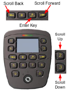
Calibrating the Steer Wheel & Axle Positions
On the overhead display, press the right arrow twice and input the service code. If you do not have a code, you must contact the local dealer and request it be reset to 55555, this is the factory set code for all Hyster and Yale lift trucks.
Enter the service and then scroll right until you see the screwdriver. Press the enter button and continue to the steer wheel or the steer axle symbols and perform the calibration one at a time. This will either clear the code or show an X on the symbol that means the calibration did not work. If the calibration worked, cycle the key and return to service, If the calibration did not work (shows the X) look for another issue such as a bad connection or broken wire. Then repeat this process.

Any question on the diagnoses of this code, register with the forum or send in a request form in the right sidebar.
Admin
Over 20 years of experience on all makes and models material handling equipment. Over 25 years automotive repair.
Recent Posts
Hyster Yale Mazda 2.0-2.2L Valve Adjustment
Valve Adjustment
Rotate crankshaft until No. 1 piston is at TDC on compression stroke (intake and exhaust valves closed).NOTE: During adjustment of valves, check position of balls in ends of…
- Home
- Forums
- Technical Troubleshooting
- Yale
- ERPO35TFN36SE082
Yale ERPO35TFN36SE082:
12824
My Yale forklift is coming up with a code of 12824 with the wrench icon and will not go. It can go up and down but nothing else. I’ve tried to Google the code but nothing comes up. Does anyone have any idea?
- Posted
14 Oct 2017 03:22 - Discussion started by
jimmy_c - New York, United States
Showing items 1 — 2 of 2 results.
Sort messages by:
Thanks allot! You’re solution was accurate!
- Posted
24 Nov 2020 19:01 - Reply by
Ronny_Gil - Israel
Steering Wheel/Steering Axle Position Sensor Out of Range Low
- Posted
14 Oct 2017 07:01 - Reply by
Keffer2017 - Tennessee, United States
Having trouble using the Discussion Forums? Contact us for help.
Forkliftaction.com accepts no responsibility for forum content and requires forum participants to adhere to the rules. Click here for more information.
Skip to content
Yale and Hyster Forklift Error Codes List
How to clear fault codes Yale and Hyster forklift
Here are the most popular error codes for the Hyster and Yale forklifts to find the diagnostic and possible cases.
On Yale and Hyster forklift fault code can be showed or can be in the system.
In order to troubleshoot, diagnose, and also possible cases error codes, you can look for your error code and all useful description in the table below
if you have any questions you can leave the question here Forklift Error codes and our technicians can help you
| Fault Codes | Diagnostic Codes | Possible Cases |
|---|---|---|
| 524223-0 | XMSN Reverse Pressure Greater Than Commanded Pressure | A. SENSOR SUPPLY OPEN CIRCUIT B. SENSOR FAILURE C. FUNCTIONAL FAILURE — MECHANICAL D. FUNCTIONAL FAILURE IN CONTROLLER |
| 524225-0 | XMSN Forward Pressure Greater Than Commanded Pressure | |
| 524223-1 | XMSN Reverse Pressure Less Than Commanded | A. LOW TRANSMISSION OIL LEVEL B. SENSOR SUPPLY OPEN CIRCUIT C. SENSOR FAILURE D. FUNCTIONAL FAILURE — MECHANICAL E. FUNCTIONAL FAILURE IN CONTROLLER |
| 524225-1 | XMSN Forward Pressure Less Than Commanded | |
| 105-3 | Intake Air Temperature (IAT) Sensor OORH | A. SENSOR WIRING OPEN CIRCUIT B. SENSOR SIGNAL SHORTED TO 5V OR BATTERY VOLTAGE C. SENSOR FAILURE D. FUNCTIONAL FAILURE IN CONTROLLER |
| 110-3 | Coolant Temperature Sensor OORH | |
| 177-3 | Transmission Oil Temperature Sensor OORH | |
| 522603-3 | Fuel Temp (LPG) Sensor OORH | |
| 105-4 | Intake Air Temperature (IAT) Sensor OORL | A. SENSOR SIGNAL SHORTED TO SENSOR GROUND. B. SENSOR SIGNAL SHORTED TO FRAME GROUND. C. SENSOR FAILURE D. FUNCTIONAL FAILURE IN CONTROLLER |
| 110-4 | Coolant Temperature Sensor OORL | |
| 177-4 | Transmission Oil Temperature Sensor OORL | |
| 522603-4 | Fuel Temp (LPG) Sensor OORL | |
| 522712-3 | Accelerator A Position Sensor OORH | A. SENSOR SUPPLY OPEN CIRCUIT (SENSOR SIGNAL GROUNDS) B. B SENSOR SIGNAL OPEN CIRCUIT C. SENSOR SIGNAL SHORTED TO BATTERY SOURCE D. SENSOR SIGNAL SHORTED TO SENSOR SUPPLY |
| 522713-3 | Accelerator B Position Sensor OORH | |
| 522712-4 | Accelerator A Position Sensor OORL | A. SENSOR SUPPLY OPEN CIRCUIT (+5 VOLTS) B. SENSOR SIGNAL A OPEN CIRCUIT C. SENSOR SIGNAL SHORTED TO FRAME GROUND D. SENSOR SIGNAL SHORTED TO SENSOR GROUND E. SENSOR FAILURE F. FUNCTIONAL FAILURE IN CONTROLLER |
| 522713-4 | Accelerator B Position Sensor OORL | |
| 1079-31 | 5VE1 & 5VE2 Simultaneously OORH | A. ELECTRONIC THROTTLE ASSEMBLY (ETA) STICKY B. SENSOR (ETA) FAILURE C. FUNCTIONAL FAILURE IN CONTROLLER |
| 51-2 | Throttle Position Sensor Signals A and B Not Tracking Correctly | |
| 51-7 | Throttle Position Sensor Signals A and B Not At Commanded Value | |
| 51-31 | Throttle Position Sensor 1 & 2 Out of Range | |
| 2350-3 | DTC 2350-3 — Front Work Lights Relay (RL4) Driver Output OORH | A. SAFETY SWITCH (IF EQUIPPED) IS DISCONNECTED B. SHORT ON RELAY DRIVER OUTPUT TO UNSWITCHED BATTERY (SEEWARNING BEFORE CONTINUING) C. SHORT ON RELAY DRIVER OUTPUT TO SWITCHED BATTERY. D. SHORT ON RELAY DRIVER OUTPUT TO ANOTHER OPERATED DEVICE E. CONTROLLER DRIVER OUTPUT TO RELAY COIL OPEN CIRCUIT F. RELAY COIL OR GROUND CONNECTION OPEN CIRCUIT G. FUNCTIONAL FAILURE IN CONTROLLER |
| 522710-3 | Throttle A Position Sensor OORH | A. SENSOR GROUND OPEN CIRCUIT B. SENSOR SIGNAL SHORTED TO SENSOR SUPPLY C. SENSOR SIGNAL SHORTED TO BATTERY SOURCE D. SENSOR FAILURE E. FUNCTIONAL FAILURE IN CONTROLLER |
| 522711-3 | Throttle B Position Sensor OORH | |
| 522710-4 | Throttle A Position Sensor OORL | A. SENSOR SIGNAL OPEN CIRCUIT B. SENSOR SUPPLY OPEN CIRCUIT C. SENSOR SIGNAL SHORTED TO FRAME GROUND D. SENSOR SIGNAL SHORTED TO SENSOR GROUND E. SENSOR FAILURE F. FUNCTIONAL FAILURE IN CONTROLLER |
| 522711-4 | Throttle B Position Sensor OORL | |
| 521-3 | Brake Pedal Position Sensor OORH | A. SENSOR GROUND OPEN CIRCUIT B. SENSOR SIGNAL SHORTED TO SENSOR SUPPLY C. SENSOR SIGNAL SHORTED TO BATTERY D. SENSOR FAILURE E. FUNCTIONAL FAILURE IN CONTROLLER |
| 523780-3 | Park Brake Position Sensor OORH | |
| 524245-3 | Seat Occupancy Position Sensor OORH | |
| 521-4 | Brake Pedal Position Sensor OORL | A. SENSOR SUPPLY OPEN CIRCUIT B. SENSOR SIGNAL OPEN CIRCUIT C. SENSOR SIGNAL SHORTED TO SENSOR GROUND D. SENSOR SIGNAL SHORTED TO FRAME GROUND E. SENSOR FAILURE F. FUNCTIONAL FAILURE IN CONTROLLER |
| 523780-4 | Park Brake Position Sensor OORL | |
| 524245-4 | Operator Presence System Sensor OORL | |
| 523833-3 | Glow Plug Relay Driver Output OORH | A. COIL DRIVER OUTPUT SHORTED TO BATTERY. B. FUNCTIONAL FAILURE IN CONTROLLER. |
| 524195-3 | Cold Start Relay Driver Output OORH | |
| 523833-4 | Glow Plug Relay Driver Output OORL | A. COIL DRIVER OUTPUT SHORTED TO GROUND. B. FUNCTIONAL FAILURE IN CONTROLLER. |
| 524195-4 | Cold Start Relay Driver Output OORL | |
| 1079-31 | 5VE1 & 5VE2 Simultaneously OORH | A. 5 VOLT «E1» SUPPLY SHORTED TO SYSTEM SUPPLY SOURCE B. 5 VOLT «E2» SUPPLY SHORTED TO SYSTEM SUPPLY SOURCE C. 5VOLT E1 AND E2 SIMULTANEOUSLY SHORTED TO SYSTEM SUPPLY SOURCE D. FUNCTIONAL FAILURE IN CONTROLLER |
| 524260-3 | 5VE2 Sensor Supply Circuit Voltage OORH | |
| 524261-3 | 5VE1 Sensor Supply Circuit Voltage OORH | |
| 96-3 | Fuel Level Sensor OORH | A. SENSOR SIGNAL SHORTED TO BATTERY B. SENSOR SIGNAL/RETURN OPEN CIRCUIT C. SENSOR SIGNAL SHORTED TO GROUND D. SENSOR FAILURE |
| 96-4 | Fuel Level Sensor OORL | |
| 523833-3 | Glow Plug Relay Driver Output OORH | A. COIL DRIVER OUTPUT SHORTED TO SYSTEM VOLTAGE B. COIL SHORT CIRCUIT C. FUNCTIONAL FAILURE IN CONTROLLER |
| 523920-3 | REV Circuit Shorted High | |
| 523930-3 | FWD Circuit Shorted High | |
| 524195-3 | Cold Start Relay Driver Output OORH | |
| 524269-3 | Transmission Enable Valve Coil Driver Output OORH | |
| 523920-4 | REV Circuit Shorted Low | A. COIL DRIVER OUTPUT SHORTED TO GROUND B. COIL/WIRING OPEN CIRCUIT C. FUNCTIONAL FAILURE IN CONTROLLER |
| 523930-4 | FWD Circuit Shorted Low | |
| 524269-4 | Transmission Enable Valve Coil Driver Output OORL | |
| 522606-10 | Post Catalytic Converter Oxygen (O2) Sensor (Slow Response) | A. OXYGEN (O2) SENSOR FAILURE B. FUNCTIONAL FAILURE IN CONTROLLER |
| 522737-10 | Pre Catalytic Converter Oxygen (O2) Sensor (Slow Response) | |
| 2000-12 | CAN Tx Failure | A. OPEN/INTERMITTENT CIRCUIT ON CAN HI, CAN LO B. CAN HI AND CAN LO SHORTED TOGETHER C. OPEN CIRCUIT ON POWER/GROUND TO CAN CONNECTED DEVICES D. STG ON CAN HI E. STS/STB ON CAN LO F. CAN CONNECTED DEVICE FAILURE |
| 2000-12 | CAN Rx Failure | |
| 2000-14 | CANbus Address Conflict Failure | |
| 522593-12 | DTC 522593-12 — CANbus Communication Loss — ECU to EPR | |
| 524233-14 | DTC 524233-14 — Boost Test Override | A. DISPLAY INTERNAL FAILURE |
| 524234-14 | DTC 524234-14 — Internal Processing Error | |
| 524236-XX | DTC 524236-XX — Boost Test Failure | |
| 190-2 | DTC 190-2 — Engine RPM Sensor Output Is Less Than Engine Speed | A. OPEN CIRCUIT IN SENSOR SUPPLY B. SENSOR SIGNAL OPEN CIRCUIT OR SHORT TO GROUND C. SENSOR SIGNAL SHORTED TO BATTERY SOURCE D. SENSOR FAILURE E. FUNCTIONAL FAILURE IN CONTROLLER |
| 190-7 | DTC 190-7 — Engine Speed Exceeds Command | |
| 522120-1 | DTC 522120-1 — Engine RPM Higher than XMSN Limit | |
| 522585-2 | DTC 522585-2 — Engine RPM Sensor (Mazda Gas ECU) | |
| 523740-3 | DTC 523740-3 — Truck has NO Forward or Reverse Motion | A. HIGH EXTERNAL MAGNETIC FIELDS B. DIRECTIONAL LEVER MECHANISM/MAGNETIC FAILURE C. DISPLAY SWITCH CLUSTER (DSC) FAILURE |
| 523740-4 | DTC 523740-4 — Truck has NO Forward or Reverse Motion | |
| 524255-3 | DTC 524255-3 — DSC Temperature OORH | A. DISPLAY SWITCH CLUSTER (DSC) IS OVERHEATED |
| 524255-4 | DTC 524255-4 — DSC Temperature OORL | |
| 524255-3 | DTC 524255-3 — DSC Temperature OORH | A. DISPLAY SWITCH CLUSTER (DSC) IS OVERHEATED |
| 524255-4 | DTC 524255-4 — DSC Temperature OORL | |
| 524255-3 | DTC 524255-3 — DSC Temperature OORH | A. DISPLAY SWITCH CLUSTER (DSC) IS OVERHEATED |
| 524255-4 | DTC 524255-4 — DSC Temperature OORL | |
| 522655-0 | DTC 522655-0 — Short Term Closed Loop Correction Bank 1 Less Than NOR -35% (Rich Engine Operation) | A. PROBLEMS THAT MAY CAUSE LEAN ENGINE OPERATION B. PROBLEMS THAT MAY CAUSE RICH ENGINE OPERATION C. SENSOR FAILURE D. FUNCTIONAL FAILURE IN CONTROLLER |
| 522655-1 | DTC 522655-1 — Short Term Closed Loop Correction Bank 1 Greater Than NOR 35% (Lean Engine Operation) | |
| 522660-0 | DTC 522660-0 — Long Term Closed Loop Correction Bank 1 Less Than NOR -30% (Rich Engine Operation) | |
| 522660-1 | DTC 522660-1 — Long Term Closed Loop Correction Bank 1 Greater Than NOR 30% (Lean Engine Operation) | |
| 523767-2 | DTC 523767-2 — DSC Fault — Arrow Down Button Stuck | A. BUTTON FAILURE |
| 523769-2 | DTC 523769-2 — DSC Fault — Arrow Up Button Stuck | |
| 524206-2 | DTC 524206-2 — DSC Fault — Rear Worklight Button Stuck | |
| 524208-2 | DTC 524208-2 — DSC Fault — Front Worklight Button Stuck | |
| 524209-2 | DTC 524209-2 — DSC Fault — Hourmeter Button Stuck | |
| 190-2 | DTC 190-2 — Crank Loss (CAM Pulse without Crank Pulse) | A. DUST/DEBRIS IN SENSOR HOUSING B. TIMING BELT NOT TENSIONED PROPERLY C. SENSOR OPEN CIRCUIT GROUND/OPEN CIRCUIT SUPPLY D. SENSOR OPEN CIRCUIT SIGNALS E. SENSOR SHORTED CIRCUIT SIGNALS F. SENSOR FAILURE G. FUNCTIONAL FAILURE IN CONTROLLER |
| 190-4 | DTC 190-4 — Crank Loss (CAM Pulse without Crank Pulse) | |
| 190-8 | DTC 190-8 — Crank/CAM Synchronization | |
| 522752-2 | DTC 522752-2 — Crank Loss (CAM Pulse without Crank Pulse) | |
| 522752-4 | DTC 522752-4 — CAM Loss (Crank Pulse without CAM Pulse) | |
| 522595-12 | DTC 522595-12 — Internal Circuity Fault Detection | A. EPR FAILURE |
| 522596-12 | DTC 522596-12 — Internal Circuity Fault Detection | |
| 524266-31 | DTC 524266-31 — Electronic Throttle Motor/Motor Connections — Short Circuit | A. CONNECTION SHORT CIRCUIT B. ETB MOTOR SHORT CIRCUIT C. ECU/ETB DRIVER FAILURE |
| 524286-31 | DTC 524286-31 — ECU — ETB Driver Component Failure | |
| 94-0 | DTC 94-0 — Primary Fuel Pressure Higher Than Expected | A. FUEL PRESSURE SENSOR WIRING FAULT B. FUEL PRESSURE FAULT C. FAULTY CONTROLLER |
| 94-1 | DTC 94-1 — Primary Fuel Pressure Lower Than Expected | |
| 520260-3 | DTC 520260-3 — Electronic Pressure Regulator (EPR) OORH | A. DEPR WIRING FAULT B. DEPR FAULT |
| 520260-4 | DTC 520260-4 — Electronic Pressure Regulator (EPR) OORL | |
| 91-2 | DTC 91-2 Sensor Signals A and B Not Tracking Correctly | A. DIFFERENCE BETWEEN SENSORS IS BEYOND ALLOWABLE TOLERANCE B. SENSOR FAILURE C. FUNCTIONAL FAILURE IN CONTROLLER |
| 515-0 | DTC 515-0 RPM Greater Than Throttle Command | A. LARGE LEAKS IN MANIFOLD B. ELECTRONIC THROTTLE ASSEMBLY (ETA) MECHANICAL ISSUES C. FUNCTIONAL FAILURE IN CONTROLLER |
| 522764-6 | DTC 522764-6 Ign/Alt — Ignition 1 Relay (RL6) Driver Output OORL | A. SHORTED RELAY COIL B. SHORT TO GROUND ON PDM RELAY DRIVER OUTPUT C. FUNCTIONAL FAILURE IN DISPLAY (DSC) |
| 168-0 | DTC 168-0 System Battery Voltage OORH | A. BATTERY FAILURE B. ALTERNATOR FAILURE C. FUNCTIONAL FAILURE IN CONTROLLER |
| 168-1 | DTC 168-1 System Battery Voltage OORL | A. BLOWN FUSE OR FAULTY WIRING HARNESS B. IGNITION WIRE FAILURE C. BATTERY FAILURE D. ALTERNATOR FAILURE E. OPERATION CYCLE TOO SHORT TO CHARGE BATTERY F. QUIESCENT CURRENT DRAW TOO HIGH DURING TRUCK OFF TIME |
| 522697-12 | DTC 522697-12 Internal Central Processor or Circuitry Faults | A. FUNCTIONAL FAILURE IN ECU CONTROLLER |
| 108-1 | DTC 108-1 Barometric Pressure Below Acceptable Limit | A. OPEN CIRCUIT SENSOR SUPPLY B. SHORTED SIGNAL CIRCUIT TO BATTERY/SENSOR SUPPLY – SIGNAL OPEN CIRCUIT C. SENSOR FAILURE D. FUNCTIONAL FAILURE IN CONTROLLER |
| 523550-3 | DTC 523550-3 Start Relay Control OORH | A. HARNESS/PDM SHORT CIRCUIT TO SWITCHED OR UNSWITCHED BATTERY B. FUNCTIONAL FAILURE IN CONTROLLER |
| 522604-3 | DTC 522604-3 Fuel Run Relay Control OORH | A. HARNESS/PDM SHORT CIRCUIT TO SWITCHED OR UNSWITCHED BATTERY B. FUNCTIONAL FAILURE IN CONTROLLER |
| 522604-4 | DTC 522604-4 Fuel Relay PWM Control OORL | A. OPEN CIRCUIT B. HARNESS/PDM SHORT TO GROUND C. FUNCTIONAL FAILURE IN CONTROLLER |
| 522604-5 | DTC 522604-5 Fuel Relay not Functioning | A. HARNESS RELAY COIL OPEN CIRCUIT B. FUNCTIONAL FAILURE IN CONTROLLER |
| 522598-3 | DTC 522598-3 LPG Lock Off OORH | A. COIL TO ECU HARNESS SHORTED TO UNSWITCHED OR SWITCH BATTERY B. COIL SHORTED TURNS C. FUNCTIONAL FAILURE IN CONTROLLER |
| 522598-4 | DTC 522598-4 LPG Lock Off OORL | A. COIL TO ECU HARNESS OPEN CIRCUIT B. COIL TO ECU HARNESS SHORT TO GROUND C. COIL OPEN CIRCUIT D. COIL SUPPLY OPEN CIRCUIT E. FUNCTIONAL FAILURE IN CONTROLLER |
| 522592-0 | EPR Pressure Greater Than Commanded | A. WORN OR DAMAGED PRIMARY OR SECONDARY SEAT B. FAULTY ELECTRONIC PRESSURE REGULATOR (EPR) ELECTRICAL CONNECTIONS C. EPR FAILURE |
| 522592-1 | EPR Pressure Less Than Commanded | A. LOW SECONDARY FUEL PRESSURE DUE TO A FUEL RESTRICTION B. FAULTY ELECTRONIC PRESSURE REGULATOR (EPR) ELECTRICAL CONNECTIONS C. EPR FAILURE |
| 524227-3 | Manual Hydraulic Lockout Coil OORH | A. COIL DRIVER OUTPUT SHORTED TO BATTERY B. COIL SHORT C. FUNCTIONAL FAILURE IN CONTROLLER |
| 524227-4 | Manual Hydraulic Lockout Coil OORL | A. COIL DRIVER OUTPUT SHORTED TO GROUND B. WIRING/COIL OPEN CIRCUIT C. FUNCTIONAL FAILURE IN CONTROLLER |
| 1239-7 | Fuel Run-Out Longer Than Expected | A. LOCK-OFF SOLENOID WIRING FAULT B. LOCK-OFF SOLENOID FAULT C. FAULTY CONTROLLER |
| 524230-3 | Rear Work Lights Relay (RL7) Driver Output OORH | A. SAFETY SWITCH (IF EQUIPPED) IS DISCONNECTED B. SHORT ON RELAY DRIVER OUTPUT TO UNSWITCHED BATTERY (SEE WARNING BEFORE CONTINUING) C. SHORT ON RELAY DRIVER OUTPUT TO SWITCHED BATTERY. D. SHORT ON RELAY DRIVER OUTPUT TO ANOTHER OPERATED DEVICE E. CONTROLLER DRIVER OUTPUT TO RELAY COIL OPEN CIRCUIT F. RELAY COIL OR GROUND CONNECTION OPEN CIRCUIT G. FUNCTIONAL FAILURE IN CONTROLLER |
| 524230-4 | Rear Work Lights Relay (RL7) Driver Output OORL | A. SHORTED RELAY COIL B. SHORT TO GROUND ON PDM RELAY DRIVER OUTPUT C. FUNCTIONAL FAILURE IN CONTROLLER |
| 522631-2 | Pre-Cat Bank 1 Sensor Fails To Switch To Rich | |
| 522762-4 | Switched Battery Voltage 3 (IGN 3) OORL | A. IGN 1 OR IGN 3 VOLTAGE OUTPUT OPEN SUPPLY B. IGN 2 VOLTAGE OUTPUT SHORTED TO GROUND C. IGN 1 OR IGN 3 OUTPUT SHORTED TO GROUND D. FUNCTIONAL FAILURE IN CONTROLLER |
| 522772-4 | Backup Lamp Driver Output OORL | A. LAMP DRIVER OUTPUT SHORTED TO GROUND B. FUNCTIONAL FAILURE IN CONTROLLER |
| 880-4 | Stop Lamp Driver Output OORL | A. LAMP DRIVER OUTPUT SHORTED TO GROUND B. FUNCTIONAL FAILURE IN CONTROLLER |
| 522760-4 | Switched Battery Voltage 1 (IGN 1) OORL | A. IGN 1 OR IGN 3 VOLTAGE OUTPUT OPEN SUPPLY B. IGN 2 VOLTAGE OUTPUT SHORTED TO GROUND C. IGN 1 OR IGN 3 OUTPUT SHORTED TO GROUND D. FUNCTIONAL FAILURE IN CONTROLLER |
| 524260-1 | 5 Volt Supply Circuit B OORL | A. 5 VOLT «A» SHORTED TO GROUND B. 5 VOLT «B» SHORTED TO GROUND C. 5 VOLT «C» SHORTED TO GROUND D. VSM FAILURE E. 5 VOLT ECU POWER SUPPLY SHORTED TO GROUND |
| 522614-7 | Throttle Not at Limp Mode Position (GM Engines Only) | A. MECHANISM STICKY COMPONENT OPERATIONAL CHECK PROCEDURE OR ACTION: 1. Turn power to OFF for no less than 30 seconds, and then to ON to clear displayed DTC. Does reported DTC to reoccur? YES: Go to Step 2. NO: Problem not verified. Resume operation. 2. Conduct a quick visual inspection of all connectors/wiring associated with the displayed fault code. Are any faults detected/observed? YES: Repair/replace connector or wiring associated with faults found. See Electrical System 2200 SRM 1142. NO: Go to Cause A. CAUSE A — MECHANISM STICKY PROCEDURE OR ACTION: 1. Turn truck power ON and start engine. 2. Check for proper operation of the throttle body and the ECU mechanism by exercising the accelerator pedal with the vehicle in neutral. For GM 2.4L gasoline and LPG engines, the engine should idle at 775 to 825 rpm with no pedal and continuing to the governor speed which should be 2675 to 2725 rpm at full pedal. For GM 4.3L gasoline and LPG engines the engine should idle at 725 to 775 rpm with no pedal and continuing to the governor speed which should be 2375 to 2425 rpm at maximum full pedal. Is the throttle mechanism operating smoothly/tracking with accelerator operation? YES: Problem corrected. Resume operation. NO: Ensure truck power is OFF. Clean any fuel residue from mechanism and go to Step 3. 3. Check for proper operation of the throttle body and the ECU mechanism by exercising the accelerator pedal with the vehicle in neutral. For GM 2.4L gasoline and LPG engines, the engine should idle at 775 to 825 rpm with no pedal and continuing to the governor speed which should be 2675 to 2725 rpm at full pedal. For GM 4.3L gasoline and LPG engines the engine should idle at 725 to 775 rpm with no pedal and continuing to the governor speed which should be 2375 to 2425 rpm at maximum full pedal. Is the throttle mechanism operating smoothly/tracking with accelerator operation? YES: Problem corrected. Resume operation. NO: Ensure truck power is OFF. Replace Electronic Throttle Body. For GM 2.4L Gasoline engines see Gasoline Fuel System, GM 2.4L Engine 900 SRM 1126. For GM 2.4L LPG engines see LPG Fuel System, GM 2.4L Engine 900 SRM 1124. For GM 4.3L Gasoline engine see Gasoline Fuel System, GM 4.3L Engine With GFI 900 SRM 1244. For GM 4.3L LPG engine see LPG Fuel System, GM 4.3L Engine With GFI 900 SRM 1242. |
| 522616-8 | Throttle Not at Command Position (GM Engines Only) | |
| 522617-5 | Throttle Not at Fully Closed/Open Position (GM Engines Only) | |
| 522760-3 | Switched Battery Voltage 1 (IGN 1) OORH | A. IGN VOLTAGE SHORTED TO UNSWITCHED BATTERY SOURCE IN PDM OR PDM/VSM HARNESS B. IGN VOLTAGE SHORTED TO UNSWITCHED BATTERY SOURCE IN PDM OUTPUT HARNESS C. IGN VOLTAGE SHORTED TO SWITCHED BATTERY SOURCE IN PDM OR PDM/VSM HARNESS D. IGN 2 VOLTAGE SHORTED TO BATTERY SOURCE E. FUNCTIONAL FAILURE IN CONTROLLER |
| 135-16 | Fuel Air Pressure minus (MAP) OORH (GM LPG Only) or and Fuel Absolute Pressure Minus (MAP) Too High | |
| 524240-4 | Washer Pump Drive Command OORL | windshield wiper pump |
| 522125-8 | Transmission Range1 Valve Current Out Of Range (TCU) | A. HIGH RESISTIVE CONNECTION B. VALVE -VE SHORTED TO BATTERY – VE/FRAME GROUND C. FUNCTIONAL FAILURE IN CONTROLLER |
| 676-3 | Glow Plug Relay Driver Output OORH | A. RELAY/COIL DRIVER OUTPUT SHORTED TO BATTERY B. RELAY/COIL DRIVER OUTPUT OPEN CIRCUIT C. RELAY/COIL DRIVER RETURN OPEN CIRCUIT D. FUNCTIONAL FAILURE IN CONTROLLER |
| 524223-4 | Transmission Reverse Pressure OORL | A. SENSOR SUPPLY OPEN CIRCUIT B. SENSOR SIGNAL OPEN CIRCUIT C. SENSOR SIGNAL SHORTED TO SENSOR GROUND D. SENSOR SIGNAL SHORTED TO FRAME GROUND E. SENSOR FAILURE F. FUNCTIONAL FAILURE IN CONTROLLER |
| 100-4 | Engine Oil Pressure OORL | A. SENSOR SUPPLY OPEN CIRCUIT B. SENSOR SIGNAL OPEN CIRCUIT C. SENSOR SIGNAL SHORTED TO SENSOR GROUND D. SENSOR SIGNAL SHORTED TO FRAME GROUND E. SENSOR FAILURE F. FUNCTIONAL FAILURE IN CONTROLLER |
| 524224-0 | XMSN Forward 2 Pressure Greater Than Commanded Pressure | A. SENSOR SUPPLY OPEN CIRCUIT B. SENSOR FAILURE C. FUNCTIONAL FAILURE — MECHANICAL |
| 168-4 | System Battery Voltage OORL | A. BATTERY FAILURE B. ALTERNATOR FAILURE C. OPERATION CYCLE TOO SHORT TO CHARGE BATTERY D. QUIESCENT CURRENT DRAW TOO HIGH DURING TRUCK OFF TIME |
| 654-5 | GM Gas Drive Injector 4 Open or Circuit Cummins-Code 332. See QSB 3.3L Troubleshooting and Repair | A. FUEL INJECTOR OPEN CIRCUIT B. INJECTOR DRIVER MODULE FAILURE C. FUNCTIONAL FAILURE IN CONTROLLER |
| 524263-1 | Uncommanded Power Down | A. TCU PROGRAM CORRUPTED OR TCU APPLICATION FILE MISMATCH B. FUNCTIONAL FAILURE IN CONTROLLER |
| 651-5 | GM Gas Drive Injector 1 Open Circuit,or Cummins-Code 322. See QSB 3.3L Troubleshooting and Repair | A. FUEL INJECTOR OPEN CIRCUIT B. INJECTOR DRIVER MODULE FAILURE C. FUNCTIONAL FAILURE IN CONTROLLER |
| 652-5 | GM Gas Drive Injector 2 Open Circuit | A. FUEL INJECTOR OPEN CIRCUIT B. INJECTOR DRIVER MODULE FAILURE C. FUNCTIONAL FAILURE IN CONTROLLER |
| 653-5 | Cummins-Code 324. See QSB 3.3L Troubleshooting and Repair | A. FUEL INJECTOR OPEN CIRCUIT B. INJECTOR DRIVER MODULE FAILURE C. FUNCTIONAL FAILURE IN CONTROLLER |
| 655-5 | GM Gas Drive Injector 5 Open Circuit | A. FUEL INJECTOR OPEN CIRCUIT B. INJECTOR DRIVER MODULE FAILURE C. FUNCTIONAL FAILURE IN CONTROLLER |
| 656-5 | GM Gas Drive Injector 6 Open Circuit | A. FUEL INJECTOR OPEN CIRCUIT B. INJECTOR DRIVER MODULE FAILURE C. FUNCTIONAL FAILURE IN CONTROLLER |
| 2023-12 | CANbus Error With Display | A. TERMINATION RESISTOR(S) OPEN CIRCUIT B. OPEN/INTERMITTENT CIRCUIT ON CAN HI, CAN LO C. CAN HI AND CAN LO SHORTED TOGETHER D. OPEN CIRCUIT ON POWER/GROUND TO CAN CONNECTED DEVICES E. STG ON CAN HI F. STS/STB ON CAN LO G. CAN CONNECTED DEVICE FAILURE |
Share This Story, Choose Your Platform!
Related Posts
Page load link
Go to Top
YALE Pallet Lift Truck Fault Codes DTC
Error: no LEDs or LCDs on
What the issue is: Inoperative
Cause of Problem: B+ and / or B- missing at controller, defective battery charger, or defective battery charger
What to do: Ensure the battery is connected, the key switch is on, and the brake override circuit is in the run position; also test your battery charger and motor controller and replace any
nonworking parts
Error: no LEDs or LCDs on
What the issue is: Forklift functions as normal
Cause of Problem: open connection between display and controller, defective display, or defective LEDs
What to do: make sure harnesses are connected at MDI and connector B on controller; test the dash display by connecting a handset to it and testing for communication; test LEDs by disconnecting
them, connecting the handset, and testing the handset; replace any non-working parts
Error: no LEDs or LCDs on
What the issue is: Forklift functions as normal
Cause of Problem: Because this condition is similar to the last, it will take a handset to determine its cause. If the handset displays “NO COMMUNICATION,” the controller is defective.
What to do: replace controller
Error: no alarm
What the issue is: Traction and hydraulic functions not working
Cause of Problem: improper startup sequence by jack operator
What to do: check brake switch, accelerator, steer handle, and hydraulic inputs
Error: AL66
What the issue is: Hydraulic function not working
Cause of Problem: battery voltage is low or controller voltage calibration is incorrect
What to do: Charge or replace battery; otherwise, use handset to determine the voltage read by the controller and compare it to an actual voltmeter reading; replace controller if the two readings
differ by more than 1.5 volts
Error: AL99
What the issue is: Traction and hydraulic functions not working
Cause of Problem: incorrect battery selected, damaged battery, or damaged connection to batter
What to do: check that you have the right voltage for your truck, manually check the voltage of your battery, inspect it for any damage, and check its connecting crimps and cables for damage as
well
Error: AL01
What the issue is: Traction and hoist functions not working
Cause of Problem: control card throttle or lift/lower calibration is out of range; control card is damaged or defective
What to do: Use the tester function on a handset to see if either calibration is greater than 1 volt at neutral; replace control card if damaged or defective, which can be checked by seeing if
both “forward switch” and “backward switch” are on at the same time when testing
Error: AL01
What the issue is: Traction and hoist functions not working
Cause of Problem: incomplete connection between control card and controller; traction reversing switch not connected; damaged or defective tiller card
What to do: Check connections between control card and controller; use a handset to test for operation of traction reversing switch; replace control card if tiller card is damaged
Error: AL02
What the issue is: Traction and hydraulic functions not working
Cause of Problem: main contactor tips are welded closed or motor field circuit is broken
What to do: disconnect power leads at contactor and test for an open circuit; check connections between motor field and controller
Error: AL04
What the issue is: traction and hydraulic functions not working
Cause of Problem: damaged connection to lowering valve; damaged lowering coil or lowering valve cartridge
What to do: check electrical connection between valve coil and controller; check lowering valve coil for resistance, replace if not approximately 17.7 ohms; replace lowering valve cartridge if
necessary
Error: AL05
What the issue is: traction and hydraulic functions not working
Cause: damaged connection to brake or brake coil damaged
What to do: check connection between electric brake and controller; check brake coil for resistance in both directions and replace if not between 27.36 and 30.24 ohms
Error: AL06
What the issue is: Traction and hydraulic functions not working
Cause of Problem: Damaged connection to traction motor; traction motor armature resistance is too low; field wires are loose or damaged; motor field winding is shorted or too low.
What to Do: Check electrical connection between traction motor, field wires, and controller; check traction motor armature for shorts; check motor field resistance and correct if not between 0.5
and 1.5 ohms; check contactor coil for resistance of 52 ohms
Error: AL07
What the issue is: traction functions reduced below 14°F or above 167°F and not working above 194°F
Cause of Problem: controller temperature is too hot or cold; controller temperature is not calibrated correctly; controller sensor or controller itself is damaged
What to do: move truck to a warmer or cooler location; use a handset to check that controller temperature matches room temperature (if not, replace controller)
Error: AL8
What the issue is: traction and hydraulic functions not working
Cause of Problem: over current in driven component
What to do: check main harness for damaged connections to main contactor, brake, and electric valve coils; check contactor, brake, and electric valve coils for correct resistance (52 ohms for
contactor, between 27.36 and 30.24 ohms for brake coil, and 17.7 ohms for electric valve coils)
Error: AL10
What the issue is: Traction and hydraulic functions not working
Cause of Problem: controller is damaged; damaged wire connection; short circuit in harness; ground between motor windings and chassis; motor field winding is shorted to chassis; field current
driver circuit has failed; watchdog hardware circuit is damaged
What to do: Cycle key switch off and on and replace controller if problem not solved; check wire connections at contactor, pump motor, and traction motor; check main harness for shorts; check for
grounds or shorts between motor windings and chassis; check motor field resistance (should be about 1.5 ohms); measure voltage between F1 and B- and F2 and B- on field current driver (should be
half the voltage between B+ and B-)
Error: AL94
What the issue is: Traction and hydraulic functions not working for one minute.
Cause of Problem: No fault is occurring. The controller is installing hour meter memory from MDI display if controller has been replaced.
What to do: No solution necessary. Fork truck will operate as soon as data transfer is complete.
Файлы
Раздел содержит файлы для скачивания по теме вилочных погрузчиков.
Инструкции по эксплуатации |
Инструкции по эксплуатации вилочных погрузчиковДоступны для скачивания инструкции и руководства для погрузчиков: Komatsu, Toyota, Yale. Все инструкции для вилочных погрузчиков содержат следующую информацию:
Руководство оператора штабелераДоступно для скачивания руководство оператора для штабелера BT. Кроме стандартной информации инструкция содержит цифровые коды предупреждений и ошибок. |
 Инструкция по эксплуатации погрузчика Yale |
| Общие положения Органы управления и контроля Устойчивость груза и погрузчика Техника безопасности Правила эксплуатации Техническое обслуживание Погрузка и транспортировка погрузчика |
|
Дата: 2015-01-08 11:05:26 Размер: 4.4 Мб Скачано: 12444 |
| Вернуться |
| Список категорий |