
Подробнее устранение неисправностей описано в руководстве по эксплуатации каждой модели.
На нашем сайте представлены запасные части для оборудования Carel.
Для подбора запасных частей Carel сообщите нам полную маркировку блока и наименование запчасти любым удобным способом.
Коды ошибок управляющих блоков для систем вентиляции и кондиционирования Carel (PCOxs электро)
| Код | Описание ошибки |
|---|---|
| E01 | Поступил сигнал от пожарной сигнализации |
| E02 | Неисправен датчик наружной температуры |
| E03 | Неисправен датчик температуры в помещении |
| E04 | Неисправен датчик температуры приточного воздуха |
| E05 | Неисправен датчик температуры возвращаемого теплоносителя |
| E08 | Неисправен датчик температуры возвращаемого теплоносителя после нагревателя второго нагрева |
| E09 | Неисправен датчик влажности приточного воздуха |
| E10 | Неисправен датчик влажности воздуха в помещении |
| E12 | Неисправен датчик температуры насыщения |
| E13 | Один или несколько аналоговых входов под ручным управлением |
| E14 | Один или несколько аналоговых выходов под ручным управлением |
| E15 | Один или несколько дискретных входов под ручным управлением |
| E16 | Один или несколько дискретных выходов под ручным управлением |
| E17 | Нет сигнала статуса от приточного вентилятора |
| E18 | Нет сигнала статуса от вытяжного вентилятора |
| E19 | Нет сигнала статуса от вытяжного и (или) приточного вентилятора |
| E20 | Низкая наружная температура для использования режима «лето» |
| E21 | Запуск заблокирован. Низкая температура возвращаемого теплоносителя или клапан в контуре нагревателя открыт менее чем на 80% (или иное значения согласно St13) |
| E22 | Защита от замерзания водяного нагревателя. Предварительная тревога |
| E23 | Защита от замерзания водяного нагревателя. Основная тревога |
| E24 | Неисправен насос в контуре водяного нагревателя |
| E25 | Защита от замерзания водяного нагревателя второго нагрева. Предварительная тревога |
| E26 | Защита от замерзания водяного нагревателя второго нагрева. Основная тревога |
| E27 | Неисправен насос в контуре водяного нагревателя 2 |
| E28 | Перегрев электронагревателя |
| E29 | Активировано оттаивание рекуператора |
| E30 | Неисправен привод ротора рекуператора |
| E31 | Неисправен компрессорно-конденсаторный агрегат (ККА) |
| E32 | Фильтр на притоке загрязнен |
| E33 | Фильтр на вытяжке загрязнен |
| E34 | Фильтр загрязнен |
| E37 | Отсутствует связь с платой расширения |
| E39 | Получен внешний сигнал тревоги |
| E40 | Перезапуск после подачи питания |
| E41 | Термозащита приточного вентилятора |
| E42 | Термозащита вытяжного вентилятора |
| E43 | Термозащита вентиляторов |
Standard Chiller/HP modulare per compressore a vite con driver CAREL
21.3
AL:001 Unit No. 1 Offline
AL:002 Unit No. 2 Offline
AL:003 Unit No.3 Offline
AL:004 Unit No.4 Offline
AL:011 Serious alarm from digital input
AL:012 Phase monitor alarm
AL:013 Evaporator flow-switch alarm
AL:014 Condenser flow-switch alarm
AL:015 Oil level alarm
AL:016 High pressure alarm (pressure switch)
AL:017 Low pressure alarm (pressure switch)
AL:018 Evaporator Pump thermal Cutout
AL:019 Condenser Pump thermal cutout
AL:020 Compressor thermal cutout
AL:021 Condenser 1 Thermal cutout
AL:022 Condenser 2 Thermal cutout
AL:031 Antifreeze alarm
AL:032 Low pressure differential alarm
AL:033 High pressure alarm (transducer)
AL:034 Low pressure alarm (transducer)
AL:035 High delivery temperature alarm
AL:036 High voltage alarm
AL:037 High current alarm
AL:041 Alarm: clock card failed or disconnected
AL:051 Evaporator pump maintenance
AL:052 Condenser pump maintenance
AL:053 Compressor Maintenance
AL:060 Probe B1 failed or not connected
AL:061 Probe B2 failed or not connected
AL:062 Probe B3 failed or not connected
AL:063 Probe B4 failed or not connected
AL:064 Probe B5 failed or not connected
AL:065 Probe B6 failed or not connected
AL:066 Probe B7 failed or not connected
AL:067 Probe B8 failed or not connected
AL:101 Diver 1 probe status
AL:102 Diver 1 EEPROM error
AL:103 Diver 1 stepped motor error
AL:104 Diver 1 battery error
AL:105 High pressure (MOP) driver 1
AL:106 Low pressure (LOP) driver 1
AL:107 Low super-heat alarm, driver 1
AL:108 Valve not shut while driver 1 being disabled
AL:109 Driver 1 high intake temperature
AL:110 Standby due to EEPROM /battery recharge / or open valve error, driver 1
AL:111 LAN disconnected, driver 1
AL:201 Diver 2 probe error
AL:202 Diver 2 EEPROM error
AL:203 Diver 2 stepped motor error
AL:204 Diver 2 battery error
AL:205 High pressure (MOP) driver 2
AL:206 Low pressure (LOP) driver 2
AL:207 Low super-heat alarm, driver 2
AL:208 Valve not shut while driver 2 being disabled
AL:209 Driver 2 high intake temperature
AL:210 Standby due to EEPROM /battery recharge / or open valve error, driver 2
AL:211 LAN disconnected, driver 2
Cod.: +030221241 Rel. 1.0 dated 25 September 03
47
Подробнее устранение неисправностей описано в руководстве по эксплуатации каждой модели.
На нашем сайте представлены запасные части для оборудования Carel.
Для подбора запасных частей Carel сообщите нам полную маркировку блока и наименование запчасти любым удобным способом.
Коды ошибок управляющих блоков для систем вентиляции и кондиционирования Carel (PCOxs электро)
| Код | Описание ошибки |
|---|---|
| E01 | Поступил сигнал от пожарной сигнализации |
| E02 | Неисправен датчик наружной температуры |
| E03 | Неисправен датчик температуры в помещении |
| E04 | Неисправен датчик температуры приточного воздуха |
| E05 | Неисправен датчик температуры возвращаемого теплоносителя |
| E08 | Неисправен датчик температуры возвращаемого теплоносителя после нагревателя второго нагрева |
| E09 | Неисправен датчик влажности приточного воздуха |
| E10 | Неисправен датчик влажности воздуха в помещении |
| E12 | Неисправен датчик температуры насыщения |
| E13 | Один или несколько аналоговых входов под ручным управлением |
| E14 | Один или несколько аналоговых выходов под ручным управлением |
| E15 | Один или несколько дискретных входов под ручным управлением |
| E16 | Один или несколько дискретных выходов под ручным управлением |
| E17 | Нет сигнала статуса от приточного вентилятора |
| E18 | Нет сигнала статуса от вытяжного вентилятора |
| E19 | Нет сигнала статуса от вытяжного и (или) приточного вентилятора |
| E20 | Низкая наружная температура для использования режима «лето» |
| E21 | Запуск заблокирован. Низкая температура возвращаемого теплоносителя или клапан в контуре нагревателя открыт менее чем на 80% (или иное значения согласно St13) |
| E22 | Защита от замерзания водяного нагревателя. Предварительная тревога |
| E23 | Защита от замерзания водяного нагревателя. Основная тревога |
| E24 | Неисправен насос в контуре водяного нагревателя |
| E25 | Защита от замерзания водяного нагревателя второго нагрева. Предварительная тревога |
| E26 | Защита от замерзания водяного нагревателя второго нагрева. Основная тревога |
| E27 | Неисправен насос в контуре водяного нагревателя 2 |
| E28 | Перегрев электронагревателя |
| E29 | Активировано оттаивание рекуператора |
| E30 | Неисправен привод ротора рекуператора |
| E31 | Неисправен компрессорно-конденсаторный агрегат (ККА) |
| E32 | Фильтр на притоке загрязнен |
| E33 | Фильтр на вытяжке загрязнен |
| E34 | Фильтр загрязнен |
| E37 | Отсутствует связь с платой расширения |
| E39 | Получен внешний сигнал тревоги |
| E40 | Перезапуск после подачи питания |
| E41 | Термозащита приточного вентилятора |
| E42 | Термозащита вытяжного вентилятора |
| E43 | Термозащита вентиляторов |
-
Bookmarks
Quick Links
2
pCO
— controllore elettronico programmabile
2
pCO
electronic programmable controller
Manuale d’installazione
User manual
LEGGI E CONSERVA
QUESTE ISTRUZIONI
READ AND SAVE
THESE INSTRUCTIONS
Related Manuals for Carel pCO2
Summary of Contents for Carel pCO2
-
Page 1
— controllore elettronico programmabile electronic programmable controller Manuale d’installazione User manual LEGGI E CONSERVA QUESTE ISTRUZIONI READ AND SAVE THESE INSTRUCTIONS… -
Page 3
Vogliamo farvi risparmiare tempo We wish to save you time and e denaro! money! LEGGI E CONSERVA Vi assicuriamo che la completa lettura We can assure you that a thorough QUESTE ISTRUZIONI di questo manuale vi garantirà una reading of this manual will guarantee READ AND SAVE THESE INSTRUCTIONS corretta installazione ed un sicuro… -
Page 5
Indice: Index: INTRODUZIONE INTRODUCTION CARATTERISTICHE GENERALI GENERAL FEATURES : SMALL, MEDIUM, LARGE : SMALL, MEDIUM, LARGE Programmability Programmabilità HARDWARE STRUCTURE ARCHITETTURA HARDWARE Instrument and accessory codes Codici degli strumenti ed accessori Meaning of the inputs/outputs Significato degli ingressi/uscite TERMINAL USER IL TERMINALE UTENTE Contrast control in LCD Display Regolazione del contrasto dei display a LCD… -
Page 7
The pCO represents the evolution of the well-known pCO electronic sviluppato da Carel e destinato a molteplici applicazioni nel campo del control, developed by Carel and designed for multiple applications in condizionamento dell’aria e della refrigerazione. La nuova gamma è… -
Page 8
32 KB E2PROM memory for memoria E2PROM per i parametri. the parameters. 1.2 Programmabilità 1.2 Programmability Carel ha la possibilità di essere programmato con il sistema di The Carel pCO can be programmed using the EasyTools development sviluppo EasyTools che offre i seguenti vantaggi: system, which offers the following advantages: •… -
Page 9
2. ARCHITETTURA HARDWARE 2. HARDWARE STRUCTURE L’architettura del pCO Carel prevede: The structure of the Carel pCO features: • il controllore pCO , dotato di microprocessore a 16 bit dedicato • the pCO control, fitted with a 16-bit microprocessor for running the… -
Page 10
Una possibile architettura hardware è così definita: The hardware structure is defined as follows: 1. terminale utente con tastiera, display e LED di segnalazione; 1. user terminal with keypad, display and LED signals; 2. pCO (versione SMALL); 2. pCO (SMALL version); 3. -
Page 11
2.1 Codici degli strumenti ed accessori 2.1 Instrument and accessory codes interface and control version versione interfaccia e controllo with 1+1 MB Flash memory code a 1+1 MB di memoria Flash codice LARGE PCO2000AL0 LARGE PCO2000AL0 MEDIUM PCO2000AM0 MEDIUM PCO2000AM0 SMALL PCO2000AS0 SMALL… -
Page 12
RS232 modem serial scheda interfaccia stampante per display grafico PCOSERPRN0 connection board for pCO PCO200MDM0 scheda controllo umidificatore a vapore Carel OEM PCOUMID000 printer interface board for graphic display PCOSERPRN0 nuova scheda controllo umidificatore a vapore control board for Carel OEM steam humidifier… -
Page 13
13. connector, address definition and LED for pLAN local network; 13. connettore, indirizzamento e LED per la rete locale pLAN; 14. hatch for inserting the RS485 (for serial connection to Carel 14. sportello per l’inserimento della scheda seriale RS485 (per supervisor) or RS232 serial board (for modem interface);… -
Page 14
connettore segnale descrizione J12-4 contatto normalmente aperto relè n. 3 J12-5 comune relè: 1, 2, 3 J13-1 comune relè: 4, 5, 6 J13-2 contatto normalmente aperto relè n. 4 J13-3 contatto normalmente aperto relè n. 5 J13-4 contatto normalmente aperto relè n. 6 J13-5 comune relè: 4, 5, 6 J14-1… -
Page 15
2.2 Meaning of the inputs/outputs This table summarises the inputs and the outputs and provides a brief description of each. connector signal description J1-1 power supply +24Vdc or 24Vac J1-2 power supply reference J2-1 universal analogue input 1 (NTC, 0/1V, 0/10V, 0/20mA, 4/20mA) J2-2 universal analogue input 2 (NTC, 0/1V, 0/10V, 0/20mA, 4/20mA) J2-3… -
Page 16
connector signal description J16-1 common relay: 9, 10, 11 J16-2 normally-open contact relay no. 9 J16-3 NO10 normally-open contact relay no. 10 J16-4 NO11 normally-open contact relay no. 11 J16-5 common relay: 9, 10, 11 J17-1 NO12 normally-open contact relay no. 12 J17-2 common relay no. -
Page 17
3. IL TERMINALE UTENTE 3. TERMINAL USER 3.1 Regolazione del contrasto dei display a LCD 3.1 Contrast control in LCD Display I modelli con display LCD 4×20 sono dotati di potenziometro per la 4×20 LCD display models have a trimmer for adjusting the display regolazione del contrasto del display. -
Page 18
3.5 Display LCD 4×20 montaggio a pannello 3.5 4×20 LCD Display for panel mounting Caratteristiche Characteristics codice PCOI000CB* code PCOI000CB* numero righe number of rows numero colonne number of columns altezza carattere (mm) font height (mm) È disponibile inoltre: Other features available: •… -
Page 19
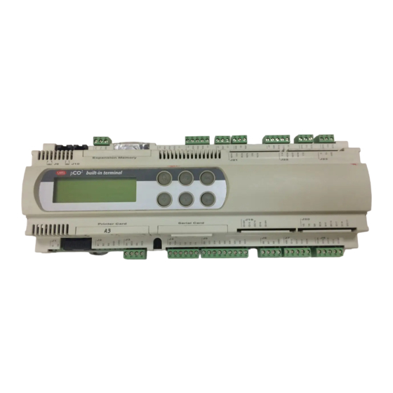
3.8 Display built-in 3.8 Built-in display Le tre versioni (SMALL, MEDIUM, LARGE) prevedono una versione The three versions (SMALL, MEDIUM, LARGE) feature a version with con display e tastiera direttamente integrata sul contenitore plastico: display and keypad directly built into the plastic case: Caratteristiche Characteristics codici*… -
Page 20
3.9.1 Utilizzo tipico dei tasti nelle applicazioni standard Carel 3.9.1 Typical use of the buttons in standard Carel applications visualizza i valori rilevati dalle sonde; displays the values measured by the probes menu menu visualizza i valori relativi alla manutenzione dei dispositivi (ore displays the values relating to the maintenance of the devices di utilizzo del dispositivo e reset contaore di funzionamento);… -
Page 21
3.10 Funzionalità e caratteristiche del terminale con 3.10 Functions and features of the terminal with display grafico graphic display I font di caratteri sono configurabili dall’utente-programmatore, sia The fonts of the digits can be configured by the user-programmer, both come stile sia come dimensione. for style and dimension. -
Page 22
3.10.2 Scheda inverter per alimentazione della lampada 3.10.2 Inverter card for powering the fluorescent light on the fluorescente (CFL) del display e connessione al pCO display (CFL) and connecting to the pCO Questa scheda consente di alimentare la lampada fluorescente di This card provides power to the fluorescent back-lighting on the display retro-illuminazione del display e permette al controllore di pilotare and allows the main board to correctly control the display used. -
Page 23
4. INSTALLAZIONE 4. INSTALLATION 4.1 Ancoraggio del pCO 4.1 Anchoring the pCO Il pCO va installato su guida DIN. Per il fissaggio alla guida DIN, è The pCO should be installed on a DIN rail. To fasten the unit to the sufficiente una leggera pressione del dispositivo preventivamente DIN rail, lightly press it against the rail. -
Page 24
4.3 Avvertenze per l’installazione — ambienti di 4.3 Installation warnings — destination and connection destinazione e collegamento environments Evitare il montaggio delle schede negli ambienti che presentino le Avoid mounting of the boards in environments with the following seguenti caratteristiche: characteristics: •… -
Page 25
4.4.1 Connecting active temperature and humidity probes Al pCO possono essere collegate tutte le sonde attive di temperatura The pCO can be connected to all the Carel series AS* active ed umidità della serie AS* Carel configurate come 0/1 V oppure come temperature and humidity probes configured as 0/1V or 4/20mA. -
Page 26
The pCO can be connected to all Carel series SPK* active pressure della serie SPK* Carel o qualsiasi sensore di pressione presente sul probes or any pressure sensor on the market with an 0/20mA or mercato con segnale 0/20 mA o 4/20 mA. Gli ingressi che possono 4/20mA signal. -
Page 27
4.4.5 Collegamento degli ingressi analogici selezionati come 4.4.5 Connecting the ON/OFF selectable analogue inputs ON/OFF Il pCO permette di configurare alcuni The pCO allows some analogue inputs to ingressi analogici come ingressi digitali puliti. be configured as clean digital inputs. The built-in terminal Gli ingressi che possono accettare questi inputs in question are B4, B5, B9, B10. -
Page 28
4.5 Collegamento degli ingressi digitali 4.5 Connecting the digital inputs Il pCO prevede fino a 18 ingressi digitali per il collegamento a The pCO features up to 18 digital inputs for connecting safety devices, sicurezze, allarmi, stati di dispositivi, consensi remoti. Questi ingressi alarms, device status, remote triggers. -
Page 29
4.5.2 Ingressi digitali alimentati a 24 Vdc 4.5.2 Digital inputs powered at 24Vdc La figura seguente rappresenta uno tra i più comuni schemi di The following figure represents one of the more common connection collegamento degli ingressi digitali a 24 Vdc. diagrams for the 24Vdc digital inputs. -
Page 30
4.5.3 Ingressi digitali alimentati a 230 Vac 4.5.3 Digital inputs powered at 230Vac La figura seguente rappresenta uno tra i più comuni schemi di The following figure represents one of the more common connection collegamento degli ingressi digitali a 230 Vac. Ogni gruppo (vedi diagrams for the 230Vac digital inputs. -
Page 31
4.6 Collegamento delle uscite analogiche 4.6 Connecting the analogue outputs Il pCO fornisce fino a sei uscite analogiche a 0/10 V optoisolate The pCO provides up to six optically-isolated 0/10V analogue outputs alimentate esternamente a 24 Vac/Vdc. La Fig. 4.6.1 rappresenta lo powered externally at 24Vac/Vdc. -
Page 32
4.7.2 Uscite digitali a relè a stato solido (SSR) 4.7.2 Solid state relay digital outputs (SSR) The pCO also features a version with solid state relays (SSR) for Il pCO prevede anche una versione con relè a stato solido (SSR) per piloting devices which require an unlimited number of switchings which comando di dispositivi che necessitano di un numero illimitato di would not be supported by electromechanical relays. -
Page 33
(code S90CONN00*) from the power board (code PCOB* and cavo telefonico (cod. S90CONN00*) proveniente dalla scheda di PCO2*) into the relative jack. The model with graphic display (code potenza (cod. PCO2*) nell’apposita presa. Il modello con display grafico PCOT00OGH0) is fitted with a further screw terminal block. -
Page 34
4.9 Installazione dell’EPROM di programma del 4.9 Installing the program EPROM in the terminal with terminale con display grafico graphic display Prima di inserire/rimuovere la EPROM togliere l’alimentazione del Before inserting/removing the EPROM disconnect the power supply to terminale con display grafico. the terminal with graphic display. -
Page 35
(nodo) ad un’altra. one location (node) to another. Ogni pCO può inoltre essere collegato alla rete di supervisione Carel, Each pCO can be connected to a CAREL supervisory network, using mediante le schede opzionali PCO2004850. -
Page 36
5.1 Indirizzamento pCO 5.1 Addressing the pCO L’indirizzo è impostabile nel range 1-31 utilizzando i dip-switch 1-5. Il The address can be set in the range 1-31 using the dip-switches 1-5. valore dell’indirizzo si ottiene tramite la Tab. 5.1.1. The value of the address is obtained as in Tab. 6.1.1. R G V Fig. -
Page 37
it. -
Page 38
5.4 Connessioni elettriche pLAN 5.4 pLAN electrical connections La connessione tra schede in pLAN si effettua usando esclusivamente Connection between boards in a pLAN network is carried out using an un cavo schermato AWG20/22 costituito da una coppia ritorta e lo AWG20/22 shielded cable, made up of a twisted pair plus shield. -
Page 39
AWG 20/22 AWG 20/22 AWG 20/22 built-in terminal built-in terminal built-in terminal Fuse Fuse Fuse Fig. 5.4.3 AVVERTENZE IMPORTANTI: IMPORTANT WARNINGS: • il collegamento a terra deve essere effettuato sulla stessa linea di • the ground connection must be made to the same ground (same terra (stesso polo di terra, per tutte le schede pCO ground pole, for all the pCO boards);… -
Page 40
Fig. 5.5..2.b Fig. 5.5.2.a built-in terminal Fig. 5.5..3 Fig. 5.5.4 Solo in ambienti particolarmente rumorosi è consigliato aggiungere le Only in particularly noisy environments should the ferrites also be ferriti anche sul connettore per pLAN (J11, cavo schermato): added on the pLAN connector (J11, shielded cable): •… -
Page 41
Communication standard RS485 baud-rate (kbit/s) 65,2 baud-rate (kbit/s) 65,2 protocollo Multimaster (protocollo di Protocol Multimaster (Carel proprietary proprietà Carel) control) lunghezza massima della rete (m) Maximum length of the network 500 metres Tab.5.6.1 — cod. +030221835 rel. 3.0 — 18.02.03… -
Page 42
) verso la chiave. PCO201KEY0: 1MB flash key for pCO to be used with 1+1MB pCO PCO201KEY0: chiave con 1 MB di flash per pCO2 da usarsi con un PCO2xxxAxx or PCO2xxxBxx. con 1+1 MB: PCO2xxxAxx o PCO2xxxBxx. PCO202KEY0: 2MB flash key for pCO… -
Page 43
6.3 Scheda seriale per supervisione e teleassistenza 6.2 RS485 serial board for supervisor and RS485: PCO2004850 telemaintenance: PCO2004850 La scheda PCO2004850 è un’opzione del controllore elettronico pCO The PCO2004850 board is an option for the pCO electronic control che permette l’interfacciamento di quest’ultimo ad una rete RS485. which allows the latter to interface with an RS485 network. -
Page 44
6.7 Board for OEM humidifier management This interface allows the control of the fundamental parameters of the 6.7 Scheda per gestione umidificatore OEM OEM humidifiers manufactured by Carel (level and conductivity of the Questa interfaccia permette di water in the… -
Page 45
The pCO board features 3 signal LEDs (red, yellow and signalling LED Sulla scheda pCO2 sono presenti 3 LED di green) that provide information on the operation of the segnalazione (rosso, giallo e verde) i quali forniscono board and the status of the connection to… -
Page 46
WinLoad not suitable or incorrect Software Protection Password. communicating with WinLoad. used as I/O Expansion Carel supervisor protocol (slave) active on serial 0. *: casi in cui pCO regredisce allo stato Basso Livello: — In fase di avvio il pCO rileva la presenza del WinLoad collegato. -
Page 47
7.3 Aggiornamento software con Winload32 In all Carel 16-bit pCO sistema controllers the resident software can be In tutti i controllori Carel a 16 bit del pCO Sistema è possibile updated from a PC. To do this, Carel provides the WinLoad32.exe pro- aggiornare il software residente utilizzando un PC. -
Page 48
Rx-/Tx- Rx+/Tx+ probe 1 probe 2 probe 3 (0/1 Vdc o 4/20 mA) +VDC Carel NTC probe PT1000 digital output 1 digital output 2 digital output 3 analog output 1 (0/10 Vdc) analog output 2 (0/10 Vdc) analog output 3 (0/10 Vdc) -
Page 49
La figura seguente (Fig. 8.2) indica una configurazione nella quale The following figure (Fig. 7.2) shows a special configuration where viene ulteriormente facilitato il cablaggio dei carichi. Bisogna comunque wiring of devices is further facilitated. In any case you must consider tenere in considerazione che il max valore di corrente sopportabile da that the max current value which can be supported by each terminal is ciascun morsetto è… -
Page 50
10/55 Hz) si consiglia di fissare tramite fascette i cavi collegati al pCO 10/55Hz), we suggest you to fasten, through fastening clamps, the a circa 3 cm di distanza dai connettori. cables connected to the pCO2 at about 3cm of distance from the connectrors. 9.2 Caratteristiche elettriche pCO alimentazione (controllore con terminale connesso) 22/40 Vdc e 24 Vac ±15% 50/60 Hz. -
Page 51
5, 8, 10, rispettivamente sulle schede SMALL, MEDIA, LARGE tipo • passivo: sensore di temperatura NTC Carel (-50/90 °C; R/T 10 kΩ ± 1% a 25 °C, =3,435 °K ± 1%), PT1000 (-100/200 °C; R/T 1000 Ω/°C) o input digitale pulito, 25/80 selezionabili via software (ingressi: B4, B5, B9, B10);… -
Page 52
9.2.2 Ingressi digitali 9.2.2 Digital inputs tipo ingressi optoisolati a 24 Vac 50/60 Hz o 24 Vdc o 230 Vac 50/60 Hz. Per gli ingressi a 230 Vac l’isolamento è principale) n. massimo 8, 14, 18, rispettivamente sulle schede: SMALL, MEDIA, LARGE, secondo le combinazioni riportate qui sotto: taglia scheda n. -
Page 53
9.2.4 Uscite digitali 9.2.4 Digital outputs n. massimo 8, 13, 18, rispettivamente sulle schede: SMALL, maximum no. 8, 13, 18, respectively on the SMALL, MEDIA, MEDIA, LARGE LARGE boards tipo a relè elettromeccanici type electromechanical relay Tab. 9.2.4.1 Tab. 9.2.4.1 Sono raggruppate a 3 con due morsetti di polo comune per un facile These are divided into 3 groups with two common pole terminals to assemblaggio dei poli comuni. -
Page 54
(per incollaggio sul contenitore plastico) adhesive on edge (for attaching to plastic case) Tab. 9.4.1.2 Tab. 9.4.1.2 Policarbonato tastiera (standard Carel) per PCOT*CB* e PCOI* Keypad polycarbonate label (Carel standard) for PCOT*CB* and PCOI* spessore (mm) 0,175 thickness (mm) 0.175… -
Page 55
9.4.2 Caratteristiche elettriche terminale 9.4.2 Terminal electrical specifications alimentazione 24 Vac (da trasformatore di Classe II e separato) per PCOI00PGL0/PCOT00PGL0 21/30 Vdc (dalla sch. di potenza per mezzo del cavo telefonico) per tutti gli altri modelli 80C52 — 8MHz condizioni di funzionamento -10T55 (-10/60 ºC, 14/149 °F) per PCOT000L60 e PCOT00PGH0 0T50 (0/50 ºC, 32/122 °F) per tutti gli altri modelli, 90% U.R. -
Page 56
10. MONTAGGIO TERMINALE UTENTE 10. USER TERMINAL MOUNTING 10.1 Montaggio a pannello 10.1 Panel mounting 10.1.1 PCOT* 10.1.1 PCOT* Riferimenti Fig. 10.1.1.1, (dimensioni in mm). Legend Fig. 7.1.1.1, (dimensions in mm). descrizione description coperchio posteriore rear cover pannello panel dima di foratura drilling template coperchio anteriore front cover… -
Page 57
11. DIMENSIONI 11. DIMENSIONS AVVERTENZA: tutte le quote riportate sulle figure che seguono sono WARINING: all the dimensions are in mm. espresse in mm. 11.1 pCO 11.1 pCO LARGE (18 moduli DIN) LARGE (18-DIN modules) built-in terminal Fuse Fig. 11.1.1 MEDIUM (18 moduli DIN) MEDIUM (18-DIN modules) built-in terminal… -
Page 58
11.2 Terminale utente 11.2 Terminal user 11.2.1 PCOT* 11.2.1 PCOT 170 mm 170 mm 170 mm 43 mm __________ __________ A____ B____ Room 1 Parem __________ Graphic Temp __________ __________ on/off alarm enter on/off alarm enter on/off alarm enter Fig. 11.2.1.1 1. -
Page 59
. Nel caso in cui sia ancora the power supplied by the pCO . If this is still near zero, contact prossima a zero contattare l’assistenza Carel; in caso contrario la the Carel service department; otherwise, the removed connection connessione tolta metteva in corto circiuto l’alimentazione. -
Page 60
Il valore di pressione “Ps” che la sonda sta inviando è così ricavabile The pressure value “Ps” sent by the probe can be calculated as (FS = Fondo Scala): follows (FS=Full Scale): Ps = (Vmis/50 — 0,004) x (FSmax — FSmin) / 0,016 + Fsmin Ps = (Vread/50 — 0.004) x (FSmax — FSmin) / 0.016 + Fsmin Esempio: la sonda impiegata ha Fsmin = -0,5 bar, Fsmax = 7 bar;… -
Page 61
2. che il dimensionamento del trasformatore di alimentazione (non 2. that the ratings of the power transformer (not supplied by CAREL) fornito da CAREL) sia corretto (vedi paragrafo ALIMENTAZIONE); are correct (see paragraph on POWER) 3. -
Page 64
Agenzia / Agency: CAREL S.p.A. Via dell’Industria, 11 — 35020 Brugine — Padova (Italy) Tel. (+39) 049.9716611 — Fax (+39) 049.9716600 e-mail: carel@carel.com — www.carel.com…
-
Bookmarks
Quick Links
2
pCO
— controllore elettronico programmabile
2
pCO
electronic programmable controller
Manuale d’installazione
User manual
LEGGI E CONSERVA
QUESTE ISTRUZIONI
READ AND SAVE
THESE INSTRUCTIONS
Related Manuals for Carel pCO2
Summary of Contents for Carel pCO2
-
Page 1
— controllore elettronico programmabile electronic programmable controller Manuale d’installazione User manual LEGGI E CONSERVA QUESTE ISTRUZIONI READ AND SAVE THESE INSTRUCTIONS… -
Page 3
Vogliamo farvi risparmiare tempo We wish to save you time and e denaro! money! LEGGI E CONSERVA Vi assicuriamo che la completa lettura We can assure you that a thorough QUESTE ISTRUZIONI di questo manuale vi garantirà una reading of this manual will guarantee READ AND SAVE THESE INSTRUCTIONS corretta installazione ed un sicuro… -
Page 5
Indice: Index: INTRODUZIONE INTRODUCTION CARATTERISTICHE GENERALI GENERAL FEATURES : SMALL, MEDIUM, LARGE : SMALL, MEDIUM, LARGE Programmability Programmabilità HARDWARE STRUCTURE ARCHITETTURA HARDWARE Instrument and accessory codes Codici degli strumenti ed accessori Meaning of the inputs/outputs Significato degli ingressi/uscite TERMINAL USER IL TERMINALE UTENTE Contrast control in LCD Display Regolazione del contrasto dei display a LCD… -
Page 7
The pCO represents the evolution of the well-known pCO electronic sviluppato da Carel e destinato a molteplici applicazioni nel campo del control, developed by Carel and designed for multiple applications in condizionamento dell’aria e della refrigerazione. La nuova gamma è… -
Page 8
32 KB E2PROM memory for memoria E2PROM per i parametri. the parameters. 1.2 Programmabilità 1.2 Programmability Carel ha la possibilità di essere programmato con il sistema di The Carel pCO can be programmed using the EasyTools development sviluppo EasyTools che offre i seguenti vantaggi: system, which offers the following advantages: •… -
Page 9
2. ARCHITETTURA HARDWARE 2. HARDWARE STRUCTURE L’architettura del pCO Carel prevede: The structure of the Carel pCO features: • il controllore pCO , dotato di microprocessore a 16 bit dedicato • the pCO control, fitted with a 16-bit microprocessor for running the… -
Page 10
Una possibile architettura hardware è così definita: The hardware structure is defined as follows: 1. terminale utente con tastiera, display e LED di segnalazione; 1. user terminal with keypad, display and LED signals; 2. pCO (versione SMALL); 2. pCO (SMALL version); 3. -
Page 11
2.1 Codici degli strumenti ed accessori 2.1 Instrument and accessory codes interface and control version versione interfaccia e controllo with 1+1 MB Flash memory code a 1+1 MB di memoria Flash codice LARGE PCO2000AL0 LARGE PCO2000AL0 MEDIUM PCO2000AM0 MEDIUM PCO2000AM0 SMALL PCO2000AS0 SMALL… -
Page 12
RS232 modem serial scheda interfaccia stampante per display grafico PCOSERPRN0 connection board for pCO PCO200MDM0 scheda controllo umidificatore a vapore Carel OEM PCOUMID000 printer interface board for graphic display PCOSERPRN0 nuova scheda controllo umidificatore a vapore control board for Carel OEM steam humidifier… -
Page 13
13. connector, address definition and LED for pLAN local network; 13. connettore, indirizzamento e LED per la rete locale pLAN; 14. hatch for inserting the RS485 (for serial connection to Carel 14. sportello per l’inserimento della scheda seriale RS485 (per supervisor) or RS232 serial board (for modem interface);… -
Page 14
connettore segnale descrizione J12-4 contatto normalmente aperto relè n. 3 J12-5 comune relè: 1, 2, 3 J13-1 comune relè: 4, 5, 6 J13-2 contatto normalmente aperto relè n. 4 J13-3 contatto normalmente aperto relè n. 5 J13-4 contatto normalmente aperto relè n. 6 J13-5 comune relè: 4, 5, 6 J14-1… -
Page 15
2.2 Meaning of the inputs/outputs This table summarises the inputs and the outputs and provides a brief description of each. connector signal description J1-1 power supply +24Vdc or 24Vac J1-2 power supply reference J2-1 universal analogue input 1 (NTC, 0/1V, 0/10V, 0/20mA, 4/20mA) J2-2 universal analogue input 2 (NTC, 0/1V, 0/10V, 0/20mA, 4/20mA) J2-3… -
Page 16
connector signal description J16-1 common relay: 9, 10, 11 J16-2 normally-open contact relay no. 9 J16-3 NO10 normally-open contact relay no. 10 J16-4 NO11 normally-open contact relay no. 11 J16-5 common relay: 9, 10, 11 J17-1 NO12 normally-open contact relay no. 12 J17-2 common relay no. -
Page 17
3. IL TERMINALE UTENTE 3. TERMINAL USER 3.1 Regolazione del contrasto dei display a LCD 3.1 Contrast control in LCD Display I modelli con display LCD 4×20 sono dotati di potenziometro per la 4×20 LCD display models have a trimmer for adjusting the display regolazione del contrasto del display. -
Page 18
3.5 Display LCD 4×20 montaggio a pannello 3.5 4×20 LCD Display for panel mounting Caratteristiche Characteristics codice PCOI000CB* code PCOI000CB* numero righe number of rows numero colonne number of columns altezza carattere (mm) font height (mm) È disponibile inoltre: Other features available: •… -
Page 19
3.8 Display built-in 3.8 Built-in display Le tre versioni (SMALL, MEDIUM, LARGE) prevedono una versione The three versions (SMALL, MEDIUM, LARGE) feature a version with con display e tastiera direttamente integrata sul contenitore plastico: display and keypad directly built into the plastic case: Caratteristiche Characteristics codici*… -
Page 20
3.9.1 Utilizzo tipico dei tasti nelle applicazioni standard Carel 3.9.1 Typical use of the buttons in standard Carel applications visualizza i valori rilevati dalle sonde; displays the values measured by the probes menu menu visualizza i valori relativi alla manutenzione dei dispositivi (ore displays the values relating to the maintenance of the devices di utilizzo del dispositivo e reset contaore di funzionamento);… -
Page 21
3.10 Funzionalità e caratteristiche del terminale con 3.10 Functions and features of the terminal with display grafico graphic display I font di caratteri sono configurabili dall’utente-programmatore, sia The fonts of the digits can be configured by the user-programmer, both come stile sia come dimensione. for style and dimension. -
Page 22
3.10.2 Scheda inverter per alimentazione della lampada 3.10.2 Inverter card for powering the fluorescent light on the fluorescente (CFL) del display e connessione al pCO display (CFL) and connecting to the pCO Questa scheda consente di alimentare la lampada fluorescente di This card provides power to the fluorescent back-lighting on the display retro-illuminazione del display e permette al controllore di pilotare and allows the main board to correctly control the display used. -
Page 23
4. INSTALLAZIONE 4. INSTALLATION 4.1 Ancoraggio del pCO 4.1 Anchoring the pCO Il pCO va installato su guida DIN. Per il fissaggio alla guida DIN, è The pCO should be installed on a DIN rail. To fasten the unit to the sufficiente una leggera pressione del dispositivo preventivamente DIN rail, lightly press it against the rail. -
Page 24
4.3 Avvertenze per l’installazione — ambienti di 4.3 Installation warnings — destination and connection destinazione e collegamento environments Evitare il montaggio delle schede negli ambienti che presentino le Avoid mounting of the boards in environments with the following seguenti caratteristiche: characteristics: •… -
Page 25
4.4.1 Connecting active temperature and humidity probes Al pCO possono essere collegate tutte le sonde attive di temperatura The pCO can be connected to all the Carel series AS* active ed umidità della serie AS* Carel configurate come 0/1 V oppure come temperature and humidity probes configured as 0/1V or 4/20mA. -
Page 26
The pCO can be connected to all Carel series SPK* active pressure della serie SPK* Carel o qualsiasi sensore di pressione presente sul probes or any pressure sensor on the market with an 0/20mA or mercato con segnale 0/20 mA o 4/20 mA. Gli ingressi che possono 4/20mA signal. -
Page 27
4.4.5 Collegamento degli ingressi analogici selezionati come 4.4.5 Connecting the ON/OFF selectable analogue inputs ON/OFF Il pCO permette di configurare alcuni The pCO allows some analogue inputs to ingressi analogici come ingressi digitali puliti. be configured as clean digital inputs. The built-in terminal Gli ingressi che possono accettare questi inputs in question are B4, B5, B9, B10. -
Page 28
4.5 Collegamento degli ingressi digitali 4.5 Connecting the digital inputs Il pCO prevede fino a 18 ingressi digitali per il collegamento a The pCO features up to 18 digital inputs for connecting safety devices, sicurezze, allarmi, stati di dispositivi, consensi remoti. Questi ingressi alarms, device status, remote triggers. -
Page 29
4.5.2 Ingressi digitali alimentati a 24 Vdc 4.5.2 Digital inputs powered at 24Vdc La figura seguente rappresenta uno tra i più comuni schemi di The following figure represents one of the more common connection collegamento degli ingressi digitali a 24 Vdc. diagrams for the 24Vdc digital inputs. -
Page 30
4.5.3 Ingressi digitali alimentati a 230 Vac 4.5.3 Digital inputs powered at 230Vac La figura seguente rappresenta uno tra i più comuni schemi di The following figure represents one of the more common connection collegamento degli ingressi digitali a 230 Vac. Ogni gruppo (vedi diagrams for the 230Vac digital inputs. -
Page 31
4.6 Collegamento delle uscite analogiche 4.6 Connecting the analogue outputs Il pCO fornisce fino a sei uscite analogiche a 0/10 V optoisolate The pCO provides up to six optically-isolated 0/10V analogue outputs alimentate esternamente a 24 Vac/Vdc. La Fig. 4.6.1 rappresenta lo powered externally at 24Vac/Vdc. -
Page 32
4.7.2 Uscite digitali a relè a stato solido (SSR) 4.7.2 Solid state relay digital outputs (SSR) The pCO also features a version with solid state relays (SSR) for Il pCO prevede anche una versione con relè a stato solido (SSR) per piloting devices which require an unlimited number of switchings which comando di dispositivi che necessitano di un numero illimitato di would not be supported by electromechanical relays. -
Page 33
(code S90CONN00*) from the power board (code PCOB* and cavo telefonico (cod. S90CONN00*) proveniente dalla scheda di PCO2*) into the relative jack. The model with graphic display (code potenza (cod. PCO2*) nell’apposita presa. Il modello con display grafico PCOT00OGH0) is fitted with a further screw terminal block. -
Page 34
4.9 Installazione dell’EPROM di programma del 4.9 Installing the program EPROM in the terminal with terminale con display grafico graphic display Prima di inserire/rimuovere la EPROM togliere l’alimentazione del Before inserting/removing the EPROM disconnect the power supply to terminale con display grafico. the terminal with graphic display. -
Page 35
(nodo) ad un’altra. one location (node) to another. Ogni pCO può inoltre essere collegato alla rete di supervisione Carel, Each pCO can be connected to a CAREL supervisory network, using mediante le schede opzionali PCO2004850. -
Page 36
5.1 Indirizzamento pCO 5.1 Addressing the pCO L’indirizzo è impostabile nel range 1-31 utilizzando i dip-switch 1-5. Il The address can be set in the range 1-31 using the dip-switches 1-5. valore dell’indirizzo si ottiene tramite la Tab. 5.1.1. The value of the address is obtained as in Tab. 6.1.1. R G V Fig. -
Page 37
it. -
Page 38
5.4 Connessioni elettriche pLAN 5.4 pLAN electrical connections La connessione tra schede in pLAN si effettua usando esclusivamente Connection between boards in a pLAN network is carried out using an un cavo schermato AWG20/22 costituito da una coppia ritorta e lo AWG20/22 shielded cable, made up of a twisted pair plus shield. -
Page 39
AWG 20/22 AWG 20/22 AWG 20/22 built-in terminal built-in terminal built-in terminal Fuse Fuse Fuse Fig. 5.4.3 AVVERTENZE IMPORTANTI: IMPORTANT WARNINGS: • il collegamento a terra deve essere effettuato sulla stessa linea di • the ground connection must be made to the same ground (same terra (stesso polo di terra, per tutte le schede pCO ground pole, for all the pCO boards);… -
Page 40
Fig. 5.5..2.b Fig. 5.5.2.a built-in terminal Fig. 5.5..3 Fig. 5.5.4 Solo in ambienti particolarmente rumorosi è consigliato aggiungere le Only in particularly noisy environments should the ferrites also be ferriti anche sul connettore per pLAN (J11, cavo schermato): added on the pLAN connector (J11, shielded cable): •… -
Page 41
Communication standard RS485 baud-rate (kbit/s) 65,2 baud-rate (kbit/s) 65,2 protocollo Multimaster (protocollo di Protocol Multimaster (Carel proprietary proprietà Carel) control) lunghezza massima della rete (m) Maximum length of the network 500 metres Tab.5.6.1 — cod. +030221835 rel. 3.0 — 18.02.03… -
Page 42
) verso la chiave. PCO201KEY0: 1MB flash key for pCO to be used with 1+1MB pCO PCO201KEY0: chiave con 1 MB di flash per pCO2 da usarsi con un PCO2xxxAxx or PCO2xxxBxx. con 1+1 MB: PCO2xxxAxx o PCO2xxxBxx. PCO202KEY0: 2MB flash key for pCO… -
Page 43
6.3 Scheda seriale per supervisione e teleassistenza 6.2 RS485 serial board for supervisor and RS485: PCO2004850 telemaintenance: PCO2004850 La scheda PCO2004850 è un’opzione del controllore elettronico pCO The PCO2004850 board is an option for the pCO electronic control che permette l’interfacciamento di quest’ultimo ad una rete RS485. which allows the latter to interface with an RS485 network. -
Page 44
6.7 Board for OEM humidifier management This interface allows the control of the fundamental parameters of the 6.7 Scheda per gestione umidificatore OEM OEM humidifiers manufactured by Carel (level and conductivity of the Questa interfaccia permette di water in the… -
Page 45
The pCO board features 3 signal LEDs (red, yellow and signalling LED Sulla scheda pCO2 sono presenti 3 LED di green) that provide information on the operation of the segnalazione (rosso, giallo e verde) i quali forniscono board and the status of the connection to… -
Page 46
WinLoad not suitable or incorrect Software Protection Password. communicating with WinLoad. used as I/O Expansion Carel supervisor protocol (slave) active on serial 0. *: casi in cui pCO regredisce allo stato Basso Livello: — In fase di avvio il pCO rileva la presenza del WinLoad collegato. -
Page 47
7.3 Aggiornamento software con Winload32 In all Carel 16-bit pCO sistema controllers the resident software can be In tutti i controllori Carel a 16 bit del pCO Sistema è possibile updated from a PC. To do this, Carel provides the WinLoad32.exe pro- aggiornare il software residente utilizzando un PC. -
Page 48
Rx-/Tx- Rx+/Tx+ probe 1 probe 2 probe 3 (0/1 Vdc o 4/20 mA) +VDC Carel NTC probe PT1000 digital output 1 digital output 2 digital output 3 analog output 1 (0/10 Vdc) analog output 2 (0/10 Vdc) analog output 3 (0/10 Vdc) -
Page 49
La figura seguente (Fig. 8.2) indica una configurazione nella quale The following figure (Fig. 7.2) shows a special configuration where viene ulteriormente facilitato il cablaggio dei carichi. Bisogna comunque wiring of devices is further facilitated. In any case you must consider tenere in considerazione che il max valore di corrente sopportabile da that the max current value which can be supported by each terminal is ciascun morsetto è… -
Page 50
10/55 Hz) si consiglia di fissare tramite fascette i cavi collegati al pCO 10/55Hz), we suggest you to fasten, through fastening clamps, the a circa 3 cm di distanza dai connettori. cables connected to the pCO2 at about 3cm of distance from the connectrors. 9.2 Caratteristiche elettriche pCO alimentazione (controllore con terminale connesso) 22/40 Vdc e 24 Vac ±15% 50/60 Hz. -
Page 51
5, 8, 10, rispettivamente sulle schede SMALL, MEDIA, LARGE tipo • passivo: sensore di temperatura NTC Carel (-50/90 °C; R/T 10 kΩ ± 1% a 25 °C, =3,435 °K ± 1%), PT1000 (-100/200 °C; R/T 1000 Ω/°C) o input digitale pulito, 25/80 selezionabili via software (ingressi: B4, B5, B9, B10);… -
Page 52
9.2.2 Ingressi digitali 9.2.2 Digital inputs tipo ingressi optoisolati a 24 Vac 50/60 Hz o 24 Vdc o 230 Vac 50/60 Hz. Per gli ingressi a 230 Vac l’isolamento è principale) n. massimo 8, 14, 18, rispettivamente sulle schede: SMALL, MEDIA, LARGE, secondo le combinazioni riportate qui sotto: taglia scheda n. -
Page 53
9.2.4 Uscite digitali 9.2.4 Digital outputs n. massimo 8, 13, 18, rispettivamente sulle schede: SMALL, maximum no. 8, 13, 18, respectively on the SMALL, MEDIA, MEDIA, LARGE LARGE boards tipo a relè elettromeccanici type electromechanical relay Tab. 9.2.4.1 Tab. 9.2.4.1 Sono raggruppate a 3 con due morsetti di polo comune per un facile These are divided into 3 groups with two common pole terminals to assemblaggio dei poli comuni. -
Page 54
(per incollaggio sul contenitore plastico) adhesive on edge (for attaching to plastic case) Tab. 9.4.1.2 Tab. 9.4.1.2 Policarbonato tastiera (standard Carel) per PCOT*CB* e PCOI* Keypad polycarbonate label (Carel standard) for PCOT*CB* and PCOI* spessore (mm) 0,175 thickness (mm) 0.175… -
Page 55
9.4.2 Caratteristiche elettriche terminale 9.4.2 Terminal electrical specifications alimentazione 24 Vac (da trasformatore di Classe II e separato) per PCOI00PGL0/PCOT00PGL0 21/30 Vdc (dalla sch. di potenza per mezzo del cavo telefonico) per tutti gli altri modelli 80C52 — 8MHz condizioni di funzionamento -10T55 (-10/60 ºC, 14/149 °F) per PCOT000L60 e PCOT00PGH0 0T50 (0/50 ºC, 32/122 °F) per tutti gli altri modelli, 90% U.R. -
Page 56
10. MONTAGGIO TERMINALE UTENTE 10. USER TERMINAL MOUNTING 10.1 Montaggio a pannello 10.1 Panel mounting 10.1.1 PCOT* 10.1.1 PCOT* Riferimenti Fig. 10.1.1.1, (dimensioni in mm). Legend Fig. 7.1.1.1, (dimensions in mm). descrizione description coperchio posteriore rear cover pannello panel dima di foratura drilling template coperchio anteriore front cover… -
Page 57
11. DIMENSIONI 11. DIMENSIONS AVVERTENZA: tutte le quote riportate sulle figure che seguono sono WARINING: all the dimensions are in mm. espresse in mm. 11.1 pCO 11.1 pCO LARGE (18 moduli DIN) LARGE (18-DIN modules) built-in terminal Fuse Fig. 11.1.1 MEDIUM (18 moduli DIN) MEDIUM (18-DIN modules) built-in terminal… -
Page 58
11.2 Terminale utente 11.2 Terminal user 11.2.1 PCOT* 11.2.1 PCOT 170 mm 170 mm 170 mm 43 mm __________ __________ A____ B____ Room 1 Parem __________ Graphic Temp __________ __________ on/off alarm enter on/off alarm enter on/off alarm enter Fig. 11.2.1.1 1. -
Page 59
. Nel caso in cui sia ancora the power supplied by the pCO . If this is still near zero, contact prossima a zero contattare l’assistenza Carel; in caso contrario la the Carel service department; otherwise, the removed connection connessione tolta metteva in corto circiuto l’alimentazione. -
Page 60
Il valore di pressione “Ps” che la sonda sta inviando è così ricavabile The pressure value “Ps” sent by the probe can be calculated as (FS = Fondo Scala): follows (FS=Full Scale): Ps = (Vmis/50 — 0,004) x (FSmax — FSmin) / 0,016 + Fsmin Ps = (Vread/50 — 0.004) x (FSmax — FSmin) / 0.016 + Fsmin Esempio: la sonda impiegata ha Fsmin = -0,5 bar, Fsmax = 7 bar;… -
Page 61
2. che il dimensionamento del trasformatore di alimentazione (non 2. that the ratings of the power transformer (not supplied by CAREL) fornito da CAREL) sia corretto (vedi paragrafo ALIMENTAZIONE); are correct (see paragraph on POWER) 3. -
Page 64
Agenzia / Agency: CAREL S.p.A. Via dell’Industria, 11 — 35020 Brugine — Padova (Italy) Tel. (+39) 049.9716611 — Fax (+39) 049.9716600 e-mail: carel@carel.com — www.carel.com…