
- Page 1
ir33 Universale electronic controller User manual… - Page 3
The technical specifi cations shown in the manual may be changed without prior warning. The liability of CAREL in relation to its products is specifi ed in the CAREL general contract conditions, available on the website www.carel.com and/or by specifi c agreements with customers; specifi cally, to the extent where allowed… -
Page 5: Table Of Contents
Content 1. INTRODUCTION 1.1 Models ……………………. 7 1.2 Functions and main characteristics ………….. 8 2. INSTALLATION 2.1 IR33: panel mounting and dimensions …………10 2.2 DN33: DIN rail mounting and dimensions ……….10 2.3 IR33 Universal wiring diagrams …………..11 2.4 DN33 Universal wiring diagrams …………..
-
Page 7: Introduction
1. INTRODUCTION IR33-DN33 Universal is a series of controllers designed for controlling the temperature in air-conditioning, refrigeration and heating units. The models diff er according to the type of power supply (115 to 230 Vac or 12 to 24 Vac, 12 to 30 Vdc) and the outputs, which based on the model may be one, two or four relays, one or four PWM outputs for controlling external solid state relays (SSR), one or two relays plus one or two 0 to 10 Vdc analogue outputs (AO) respectively.
-
Page 8: Functions And Main Characteristics
Below is a description of the accessories for the IR33/DN33 Universal: the testing phase. ComTool programming tool (downloadable from http://ksa.carel.com) With this useful tool, the controller can be programmed from any PC, saving the diff erent confi gurations to fi les that can be loaded during the…
- Page 9
Used to connect the DN33 via the RS485 serial network to the PlantVisor supervisory system. Fig. 1. d Analogue output module (code CONV0/10A0) Converts the PWM signal for solid state relays (SSR) to a standard 0 to 10 Vdc or 4 to 20 mA signal. For models IR/DN33A7**** and IR33D7**** only. -
Page 10: Installation
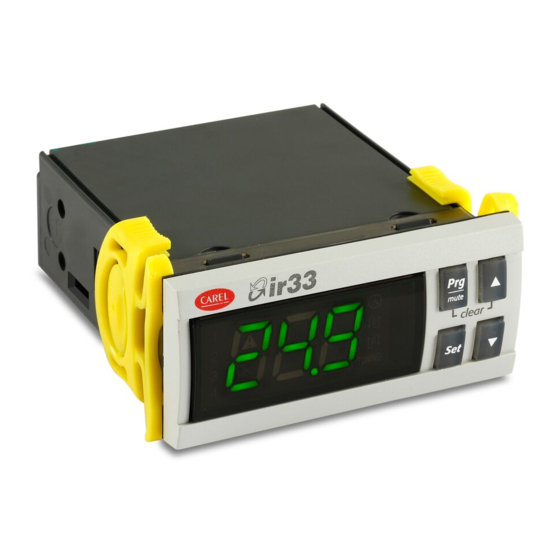
2. INSTALLATION 2.1 IR33: panel mounting and dimensions 2.2.1 DN33 optional connections 70.5 76.2 dima di foratura drilling template 71×29 mm 80.6 IROPZKEY**: IROPZ485S0: Fig. 2. a Chiave di Interfaccia scheda programmazione seriale RS485 Programming key intelligente Smart serial board interface RS485 Fig.
-
Page 11: Ir33 Universal Wiring Diagrams
2.3 IR33 Universal wiring diagrams The models with 115 to 230 Vac and 12 to 24 Vac power supply have the same wiring diagram. In the 230 Vac models, the line (L) is connected to terminal 6 and the neutral (N) to terminal 7. Relays IR33V7HR20 / IR33V7HB20/ IR33V7LR20 IR33W7HR20 / IR33W7HB20 / IR33W7LR20…
-
Page 12: Dn33 Universal Wiring Diagrams
2.4 DN33 Universal wiring diagrams For models with the same type of outputs, only the wiring diagram of the model with the most outputs has been shown (models : “Z”, “A”, “E”). DN33V7HR20 / DN33V7HB20 DN33V7LR20 / DN33W7LR20 / DN33Z7LR20 DN33W7HR20 / DN33W7HB20 Relays DN33Z7HR20 / DN33Z7HB20…
-
Page 13: Connection Diagrams
2.5 Connection diagrams 2.5.1 Connection to the CONV0/10A0 and CONVONOFF0 modules (accessories) The CONV0/10A0 and CONVONOFF0 modules convert a PWM output for SSR to a 0 to 10 Vdc analogue output and ON/OFF relay output respectively. Below is an example of an application that uses model DN33A7LR20.
-
Page 14: Installation
The parameters can only be copied between controllers with the same 2.6 Installation code. The UPLOAD operation can, however, always be performed. To install the controller, proceed as follows, with reference to the wiring diagrams: 2.7.1 Copying and downloading the parameters 1) connect the probes and power supply: the probes can be installed The following operations are used for the UPLOAD and/or DOWNLOAD up to a maximum distance of 100 m from the controller, using…
-
Page 15: User Interface
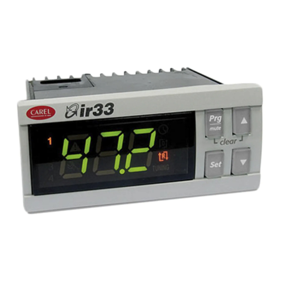
3. USER INTERFACE The front panel contains the display and the keypad, made up of 4 buttons, that, when pressed alone or combined with other buttons, are used to program the controller. IR33 Universal front panel Fig. 3. a 3.1 Display The display shows temperature in range -50 to +150°C.The temperature is displayed with resolution to the tenths between –19.9 and + 59.9 °C Alternatively, displays the value of one of the analogue or digital inputs…
-
Page 16: Keypad
3.2 Keypad Pressing the button alone: • If pressed for more than 5 seconds, accesses the menu for setting the type P parameters (frequent); • Mutes the audible alarm (buzzer) and deactivates the alarm relay; • When editing the parameters, pressed for 5 s, permanently saves the new values of the parameters; •…
- Page 17
3.3.3 Setting type P parameters Type P parameters (frequents) are indicated by a code beginning with the letter P, followed by one or two numbers. Press for more than 5 seconds (if an alarm is active, the buzzer is muted), the display shows the code of the fi rst modifi able type P parameter, P1;… -
Page 18: Example: Setting The Current Date/Time And The On/Off Times
All the modifi cations made to the parameters, temporarily stored in the RAM, can be cancelled, returning to the standard display by not pressing any button for 60 seconds. The values of the clock parameters, however, are saved when entered. If the controller is powered down before pressing , all the modifi cations made to the parameters will be lost…
- Page 19
3.4.3 Setting the default parameters To set the parameters to the default values: • Power down the controller; • Press • Power up the controller holding the button, until the message “Std” is shown on the display. This will cancel any changes made and restore the original values set by the manufacturer. -
Page 20: Using The Remote Control (Accessory)
3.4.10 Displaying the inputs • Press : the current input will be displayed, alternating with the value: b1 : probe 1; b2 : probe 2; di1 : digital input 1; di2 : digital input 2. • Press to select the input to be displayed; •…
- Page 21
3.5.2 Activating and deactivating the use of the remote control Button Immediate function Delayed function used to enable the remote control; each instrument displays its own enabling code ends operation using the remote control, cancelling all changes made to the parameters used to display the pressing and holding for 5s… -
Page 22: Commissioning
4. COMMISSIONING °C 4.1 Confi guration set point The confi guration parameters should be set when commissioning the process value controller, and involve: • serial address for the network connection; • enabling the keypad, buzzer and the remote control (accessory); •…
-
Page 23: Functions
5. FUNCTIONS 5.1 Probes (analogue inputs) Par. Description Def Min Max UoM St1 Set point 1 c21 c22 °C/°F The probe parameters are used to : St2 Set point 2 c23 c24 °C/°F • set the type of probe 1=direct •…
- Page 24
5.2.2 Reverse (parameter c0=2) 5.2.4 PWM (parameter c0=4) “Reverse” operation is similar to ”direct” operation, however the outputs The control logic in PWM mode uses the dead zone, with the outputs are activated when the value being controlled decreases, starting from activated based on pulse width modulation (PWM). - Page 25
St1/St2 Set point 1/2 Mod. V Mod. W “Direct” diff erential OUT1 (LOW ALARM) OUT1 OUT2 (HIGH ALARM) “Reverse” diff erential OUT1 Output 1 Probe 1 For models W & Z the activations of the outputs are equally distributed inside the diff erential set (P1/P2). Parameter c29 is not active in mode 6. -
Page 26: Validity Of Control Parameters (Parameters St1,St2,P1,P2,P3)
• 5.2.9 Direct/reverse with two set points (par. c0=9) Mode 6: does not consider the diff erential P3. The changeover of digital input 1 means the outputs consider set point 2 rather than In this mode, available only on the models with 2 or 4 outputs, half of the set point 1.
- Page 27
5.5.1 Dependence (parameters c34,c38,c42,c46) 5.5.3 Activation (parameters c36,c40,c44,c48) This the parameter that determines the specifi c function of each output. The parameter is active only if the output is the control output It links an output to a set point (control output) or a specifi c alarm (alarm (“dependence”=1,2,16,17) or TIMER (“dependence”=15). - Page 28
output, that is, for ON/OFF operation, the deactivation point of the output 5.5.6 Deactivation restriction (par. d35,d39,d43,d47) or, for PWM operation, the point where the output has the minimum value In normal operating conditions, the deactivation sequence should be as (ON time =0). -
Page 29: Additional Remarks On Special Operation
The following must also be set: The PWM (or analogue) outputs will follow the operation indicated in • “type of output “ =1, modulating output the fi gure. In practice, in the dead zone the output maintains the level of •…
-
Page 30: Outputs And Inputs
Modes 1 & 2 in diff erential operation (c19=1). In diff erential operation, St1 must compare against ‘B1-B2’ instead of B1. Time In special operation (c33=1) the outputs can be set with “dependence”=2: c6 & d1 are not operative for the PWM outputs. diff erential operation is therefore overridden and the outputs are linked to St2/P2 compared against B1.
- Page 31
c29=0 Input not active Par. Description Def Min Max UM c12 PWM cycle time 20 0.2 999 s c29=1 Immediate external alarm with automatic reset. The alarm condition relates to the contact being open. When the alarm Validity: c0=4; condition ceases (contact closes), normal control resumes and any alarm In special operation c12 is active in any mode if “type of output”=1 output is deactivated. -
Page 32: Control
6. CONTROL ON/OFF and PID control 6.3 Auto-Tuning (parameter c64) The controller leaves the factory with default settings of the PID The controller can operate with two types of control: parameters; these allow standard PID control, but are not optimised for the system that IR33 controls.
-
Page 33: Operating Cycle
procedure can be repeated to further tune the values. This is useful when Example 1: Heating cycle with infi nite temperature control the loads have changed since the fi rst procedure was performed, or to allow fi ner tuning. The controller in this case can manage the system using the PID parameters, and further Auto-Tuning will have the eff ect of improving control.
- Page 34
Example 1: T2< 8°C. To do this, simply connect OUT2 in series with OUT3 and OUT4, A refrigeration unit with 2 compressors must lower the temperature of then make OUT2 active only when B1 (T2) is greater than 8°C. the water by 5°C. Set c33=1: the changes to be made to the special parameters are: OUT2 OUT3… - Page 35
6.5.3 Compensation in cooling (parameter c19=2) from falling below 10°C, a minimum limit must be set for St1, with c21=10. The graph below shows the trend in St1. Compensation in cooling may either increase or decrease the value of St1, depending on whether c4 is positive or negative. St1_comp St1 only changes if the temperature B2 exceeds St2: c4=-0,5… - Page 36
6.5.5 Continuous compensation (parameter c19=4) ABILITAZIONE/ ENABLE The compensation of St1 is active for values of B2 other than St2: with C19=5 this value of c19, parameter P2 can be used to defi ne a dead zone around St2 in which compensation is not active, that is, when the value read by B2 is between St2-P2 and St2+P2, compensation is disabled and St1 is not changed: if B2 is greater than (St2+P2), eff ective St1 = St1+ [B2-(St2+P2)]*c4… -
Page 37: Table Of Parameters
7. TABLE OF PARAMETERS Par. Description Note Def Max UoM Type CAREL SVP ModBus® Icon Set point 1 °C/°F A Set point 2 °C/°F A Operating mode 1=direct 2=reverse 3=dead zone 4=PWM 5=alarm 6=direct/reverse from digital input1 7=direct: set point & diff erential from digital input 1 8=reverse: set point &…
- Page 38
Par. Description Note Def Max UoM Typ. CAREL SVP ModBus® Icon High temperature alarm threshold °C/°F if P29=0, P26=0 : threshold disabled if P29=1, P26=200 : threshold disabled Alarm diff erential °C/°F Alarm delay time Type of alarm threshold 0=relative; 1=absolute… - Page 39
Par. Description Note Def Min Max UoM Typ. CAREL SVP ModBus® Icon Activation of output 4 -100 -100 Diff erential/logic of output 4 -100 Activation restriction for output 4 Deactivation restriction for output 4 Minimum value of modulating output 4(*) -
Page 40: Variables Only Accessible Via Serial Connection
ModBus® : variable address with ModBus® protocol on 485 serial card. The selection between CAREL and ModBus® protocol is automatic. For both of them the speed is fi xed to 19200 bit/s. All the devices connected to the same network must feature the same serial parameters: — 8 data bit;…
-
Page 41: Alarms
8. ALARMS 8.1 Types of alarms There are two types of alarms available: • high temperature (E04) and low temperature (E05); • serious alarms, that is, all the others. The data memory alarms E07/E08 always cause the control to shutdown. “Alarm”…
-
Page 42: Table Of Alarms
8.4 Table of alarms Message Cause of the alarm Icon on display Alarm relay Buzzer Reset Code Control action Checks/solutions on display shown in alarm queue ALx_TYPE Probe B1 fault automatic Depends on Check probe connections fl ashing parameter c10 Probe B2 fault automatic If c19=1 &…
- Page 43
8.5.3 Status of the control outputs with alarm from Description digital input (parameter c31) Status of the control outputs with probe alarm Parameter c31 determines the action on the control outputs if an alarm 0=All outputs OFF from digital input E03 is active (see c29 and c30). When OFF is selected, 1= All outputs ON the controller shuts down immediately and the timers are ignored. -
Page 44: Technical Specifications And Product Codes
Note: in the installation, keep the power and load connections separate from the probe, digital inputs, repeater display and supervisor cables. Type of probe Std. CAREL NTC 10kΩ at 25°C, range from –50T90°C measurement error: 1°C in range from –50T50°C 3°C in range from +50T90°C…
-
Page 45: Cleaning The Controller
Device designed to be hand-held or integrated in hand-held devices Software class and structure Class A Front panel cleaning Only use neutral detergents and water Carel serial network interface External, available on all models Programming key Available on all models Type of connection Size…
-
Page 46: Software Revisions
9.4 Software revisions REVISION Description Functions active starting from software version higher than FUNCTION Parameter Soft start 0 to 10 V outputs c19=5,6 / c66, c67 d36, d40, d44, d48 d37, d41, d45, d49 ir33 universale +030220801 — rel. 1.0 — 16.04.2008…
- Page 48
CAREL is a registered trademark of CAREL S.p.A. in Italy and/or other countries. © CAREL S.p.A. 2008 all rights reserved CAREL reserves the right to modify the features of its products without prior notice. www.carel.com…
-
Bookmarks
Quick Links
Updated:
17/03/2010
CAREL ir33
Q u i c k r e f e r e n c e H a n d b o o k
Ver. 1.1
Pag.1/12
Eng
Related Manuals for Carel ir33
Summary of Contents for Carel ir33
-
Page 1
Updated: 17/03/2010 CAREL ir33 Q u i c k r e f e r e n c e H a n d b o o k Ver. 1.1 Pag.1/12… -
Page 2: Main Features Of The Instrument
Updated: 17/03/2010 MAIN FEATURES OF THE INSTRUMENT USER INTERFACE ON/OFF switch button – UP button to increase temperature values DOWN button to decrease values — Activates/deactivates the manual defrost SET temperature button Prg/mute button Malfunctioning or failure warning icon High/Low temperature alarm icon icon is ON when defrost process starts icon is ON when compressor starts icon is ON when evaporator fans starts…
-
Page 3
“0” that indicates the password prompt Press UP button to set the password – CAREL thermoregulators are provided with password set to 11 (the code of the password allows access to the configuration parameters) -
Page 4
Updated: 17/03/2010 MANUAL Manual defrost is activated or deactivated if DEF/DOWN button is keep DEFROST pressed more than 5 seconds. When defrost starts display shows dFb (defrost begining) Defrost’s warning icon is ON when defrost is active Defrost can be interrupted simply by pressing again the DEF/DOWN button more than 5 seconds. -
Page 5
Updated: 17/03/2010 HOW TO CHECK To check current temperature measured by a single installed probe, CAVITY PROBE proceeds as follow: TEMPERATURE 1. refers to the previous step how to get in the configuration parameter session — type C parameter 2. scroll the configuration parameter list, by using UP/DOWN buttons, until display shows the parameter /C1 (calibration or offset for cavity probe) 3. -
Page 6
Updated: 17/03/2010 TABLE OF OPERATING PARAMETERS N° Code Range U.M. Description TEMPERATURE PROBE MANAGEMENT PARAMETERS 0…15 Measurement stability 0…15 Probe display response 0…100 Virtual probe Flag Selection °C or °F Flag Decimal point 1…6 Display on terminal 0…6 Display on external terminal 0…2 Type of probe 0…3… -
Page 7
Updated: 17/03/2010 N° Code Range U.M. Description 0…1 Flag Enable autostart function in PD 0…1 Flag Select Pump down by time or pressure 0…250 Seconds Second compressor delay DEFROST MANAGEMENT PARAMETERS 0…4 Flag Type of defrost 0…250 Hours Interval between defrosts -50…200 °C/°F End defrost temperature, evaporator… -
Page 8
Clean Alarm counter reset NOTE 1: Above operating parameters are available for all range of CAREL thermoregulators. Particularly all green highlighted parameters are available on new CAREL controller ir33 IRELF0HN245, currently installed on HD cabinets and counters NOTE 2: Blu highlighted operating parameters listed above are not influential for the functioning of the appliance. -
Page 9
Updated: 17/03/2010 SERVICE ALLARMS AND SIGNALS SERVICE ALARMS SERVICE ALARMS DUE TO MALFUNCTIONING OR FAILURE PRODUCE A WARNING SIGNALS ON THE DISPLAY BY MEAN OF THE SERVICE ICON CAVITY PROBE In case of cavity probe faulty or malfunctioning display shows the error FAULT signal rE and E0 (cavity probe S1 fault) alternately The appliance works however and compressor starts are controlled by… -
Page 10
Updated: 17/03/2010 TEMPERATURE ALARMS AND SIGNALS TEMPERATURE HIGH OR LOW TEMPERATURE ALARMS DUE TO MALFUNCTIONING OR ALARMS COMPONENTS FAILURE PRODUCE A WARNING SIGNALS ON THE DISPLAY BY MEAN OF THE ALARM ICON In case of low cavity temperature, referred to the cavity probe, the TEMPERATURE display shows a flashing error code LO. -
Page 11
Updated: 17/03/2010 CONNECTIONS Follows all electrical connections available on ir33 CAREL controller , currently used in production IRELC0HN215 (646R05100) installed on STD BEN and CL freezer counter and STD BEN cabinet provided with internal light IRELF0EN215 (646R04700) installed on all STD BEN refrigerated counters, 400Lt refrigerated cabinets and all STD BEN cabinets without light Ver. -
Page 12
Updated: 17/03/2010 IRELF0HN245 (646R09300) installed on HD counters and cabinets IRELF0EN225 installed on digital ROLL–IN IRELF0EHD15 installed on 400Lt FREEZER cabinet Ver. 1.1 Pag.12/12…
PDF инструкция · 64 страниц(ы) русский
инструкцияCarel ir33

ir33 platform
ir33
ir33 power
ir33 DIN
powercompact
powercompact small
mastercella
Руководство пользователя
Посмотреть инструкция для Carel ir33 бесплатно. Руководство относится к категории контроллеры, 4 человек(а) дали ему среднюю оценку 8.3. Руководство доступно на следующих языках: русский. У вас есть вопрос о Carel ir33 или вам нужна помощь? Задайте свой вопрос здесь
Главная
Не можете найти ответ на свой вопрос в руководстве? Вы можете найти ответ на свой вопрос ниже, в разделе часто задаваемых вопросов о Carel ir33.
Аккумулятор в моем устройстве контроллер начал ржаветь. Безопасно ли пользоваться устройством?
Инструкция Carel ir33 доступно в русский?
Не нашли свой вопрос? Задайте свой вопрос здесь
-
Contents
-
Table of Contents
-
Bookmarks
Quick Links
ir33 Universale
electronic control
User manual
I n t e g r a t e d C o n t r o l S o l u t i o n s & E n e r g y S a v i n g s
Related Manuals for Carel ir33 Universale
Summary of Contents for Carel ir33 Universale
-
Page 1
Universale electronic control User manual I n t e g r a t e d C o n t r o l S o l u t i o n s & E n e r g y S a v i n g s… -
Page 3
The technical specifi cations shown in the manual may be changed without prior warning. The liability of CAREL in relation to its products is specifi ed in the CAREL general contract conditions, available on the website www.carel.com and/or by specifi c agreements with customers; specifi cally, to the extent where allowed… -
Page 5: Table Of Contents
Content 1. INTRODUCTION Models ………………….7 Functions and main characteristics …………8 2. INSTALLATION 2.1 IR33: panel mounting and dimensions ……….10 2.2 DIN rail mounting and dimensions …………11 2.3 IR33/DN33 with temperature inputs — wiring diagrams ……. 12 2.4 IR33/DN33 Universale with universal inputs — wiring diagrams ..
-
Page 7: Introduction
Max range -199 to 800 on models with temperature inputs only and M the 24 Vac/24Vdc 4 to 20 mA Max range -199 to 800 power supply on models with universal inputs. Tab. 1.b ir33 universale +030220801 — rel. 2.1 — 21.06.2011…
-
Page 8: Functions And Main Characteristics
Starting fi rmware revision 2.0, IR33 Universale can manage two circuits the testing phase. with independent PID control. New software functions have also been introduced, such as speed-up, cut-off and forcing the output from digital input, which can be selected for each output.
-
Page 9
ON/OFF outputs are required for the control functions or alarms. Fig. 1.h ir33 universale +030220801 — rel. 2.1 — 21.06.2011… -
Page 10: Installation
IR33 — optional connections Temperature inputs Universal inputs Chiave di programmazione Interfaccia scheda seriale RS485 Interfaccia scheda seriale RS485 Chiave di programmazione Programming key Serial board interface RS485 Programming key Serial board interface RS485 ir33 universale +030220801 — rel. 2.1 — 21.06.2011…
-
Page 11: Din Rail Mounting And Dimensions
2.2.1 DN33 — Temperature inputs 2.2.2 DN33 — Universal inputs 2.2.3 DN33 — optional connections Interfaccia seriale RS485. Serial board RS485. Interfaccia seriale RS485 Serial board RS485 Chiave di programmazione Programming key ir33 universale +030220801 — rel. 2.1 — 21.06.2011…
-
Page 12: Ir33/Dn33 With Temperature Inputs — Wiring Diagrams
8A 2FLA UL 873 8A 2FLA 0…10 V Relays 12LRA 12LRA + 0-10 Vdc SERIAL and KEY SERIAL and KEY 10 11 12 10 11 12 POWER POWER DI1 DI2 SUPPLY SUPPLY ir33 universale +030220801 — rel. 2.1 — 21.06.2011…
-
Page 13
PWM or 0 to 10 Vdc analogue output reference Y1/Y2/Y3/Y4 PWM or 0 to 10 Vdc analogue output signal C/NC/NO Common/Normally closed/Normally open (relay output) B1/B2 Probe 1/Probe 2 DI1/DI2 Digital input 1/ Digital input 2 ir33 universale +030220801 — rel. 2.1 — 21.06.2011… -
Page 14: Ir33/Dn33 Universale With Universal Inputs — Wiring Diagrams
PWM or 0 to 10 Vdc analogue output signal C/NC/NO Common/Normally closed/Normally open (relay output) -B1, +B1, B1 / -B2, +B2, B2 Probe 1/Probe 2 DI1/DI2 Digital input 1/ Digital input 2 ir33 universale +030220801 — rel. 2.1 — 21.06.2011…
-
Page 15: Ir33/Dn33 Universale With Universal Inputs — Probe Connections
— make sure the wire is stripped for 8-10 mm; — use a fl at-head screwdriver to press the orange locking device; — insert the wire in the hole underneath; — release the orange locking device. ir33 universale +030220801 — rel. 2.1 — 21.06.2011…
-
Page 16: Connection Diagrams
G0). This allows just one transformer to be used. -B2 +B2 B2 +12 V DI1 GND -B1 +B1 B1 +5 V AC 24 V/ DC 24 V 450 mA MAX 230 Vac 24 Vac Fig. 2.c ir33 universale +030220801 — rel. 2.1 — 21.06.2011…
-
Page 17: Installation
Case 2: a series of controllers connected in a network powered by diff erent transformers (G0 not earthed). Typical application for multiple controllers in diff erent electrical panels. 230 Vac 230 Vac 230 Vac 24 Vac 24 Vac 24 Vac Fig. 2.e ir33 universale +030220801 — rel. 2.1 — 21.06.2011…
-
Page 18: Programming Key
Other signals or the fl ashing of the LED indicates that problems have occurred: refer to the table; 4. at the end of the operation, release the button, after a few seconds the LED goes OFF; 5. remove the key from the controller. ir33 universale +030220801 — rel. 2.1 — 21.06.2011…
-
Page 19: User Interface
The user can select the standard display by suitably setting parameter c52, or by pressing (DOWN) to select one of the possible options (b1, b2, di1, di2, St1, St2) and confi rming by pressing Set. See paragraph 3.4.11. ir33 universale +030220801 — rel. 2.1 — 21.06.2011…
-
Page 20: Keypad
St2; • press until reaching the required value; • press Set to confi rm the new value of St2; • the display returns to the standard view. Fig. 3.e Fig. 3.d ir33 universale +030220801 — rel. 2.1 — 21.06.2011…
-
Page 21: Setting The Current Date/Time And The On/Off Times
5. To return to the list of main parameters, press 6. Select and modify parameter toF together with the corresponding hour and minutes, repeating the sequence from point 2 to 5. ir33 universale +030220801 — rel. 2.1 — 21.06.2011…
-
Page 22
5 seconds. Termination of the operating cycle is indicated by the message “StP” (stop). 3.4.10 Auto-Tuning activation See the chapter on Control. Auto-Tuning is incompatible with independent operation (c19=7). Fig. 3.l ir33 universale +030220801 — rel. 2.1 — 21.06.2011… -
Page 23: Using The Remote Control (Accessory)
The buttons can be divided into three groups, based on their functions: • Enabling/disabling the use of the remote control (Fig. 1); • Remote simulation of the controller keypad (Fig. 2); • Direct display/editing of the most common parameters (Fig. 3). ir33 universale +030220801 — rel. 2.1 — 21.06.2011…
-
Page 24
In Levels 1 and Level 2, the buttons repeat the corresponding functions on the controller keypad. In this way, all the controller parameters can be displayed and set, even those without shortcut buttons. remote control Fig. 3.s ir33 universale +030220801 — rel. 2.1 — 21.06.2011… -
Page 25: Commissioning
When switching ON and OFF the control output protection times are Parameter d57 acts on circuit 2 if independent operation is active. taken into consideration; Par. Description Soft start min/°C Soft start circuit 2 min/°C ir33 universale +030220801 — rel. 2.1 — 21.06.2011…
-
Page 26: Functions
5.1 Temperature unit of measure 4= PT1000 range (-199T+800°C) 5= Pt100 range (-50T+200°C) On IR33 Universale the temperature unit of measure can be changed 6= Pt100 range (-199T+800°C) from degrees Celsius to degrees Fahrenheit using parameter c18. 7= J thermocouple range (-50T+200°C) Par.
-
Page 27: Standard Operating Modes (Parameters St1,St2,C0,P1,P2,P3)
OUT1 OUT2 diff erent physical values, for example temperature-humidity using independent operation (c19=7) with combined active probe (e.g. CAREL DPWC*) with two 4 to 20 mA outputs. For the explanation of the types of control based on parameter c19, see the chapter on “Control”.
-
Page 28
Mod. Z / A / E (*) In the event of alarms from digital input, the unit of measure is seconds (s). 100% OUT2 OUT1 OUT3 OUT4 P1/2 P1/2 P2/2 P2/2 Fig. 5.f ir33 universale +030220801 — rel. 2.1 — 21.06.2011… -
Page 29
When alarms E04/E15 and E05/E16 are active, the buzzer can be muted by pressing Prg/mute. The display remains active. ir33 universale +030220801 — rel. 2.1 — 21.06.2011… -
Page 30: Validity Of Control Parameters (Parameters St1,St2,P1,P2,P3)
, then return to special operation with c33=1. Setting c33 from 1 to 0, the controller cancels all changes to the “special parameters”, which return to the values dictated by c0.. ir33 universale +030220801 — rel. 2.1 — 21.06.2011…
-
Page 31: Special Operating Modes
Dependence = 16: the output is the control output: the association St1/ indicates the point where the output has the maximum value. P1 and St2/P2 depends on the status of digital input 1. If the input is ir33 universale +030220801 — rel. 2.1 — 21.06.2011…
-
Page 32
By setting this restriction, the correct sequence is observed even when timers have been set. The output with the activation restriction set to ‘x’ (1,2,3) will ir33 universale +030220801 — rel. 2.1 — 21.06.2011… -
Page 33
(d36, d40, “Reverse” diff erential d44, d48) Maximum value of modulating output 1 maximum set (d37, d41, OUT1 Output 1 d45, d49) Probe 1 OFF respecting c6, c7,d1, c8, c9 Tab. 5.l ir33 universale +030220801 — rel. 2.1 — 21.06.2011… -
Page 34: Additional Remarks On Special Operation
Activation is delayed to avoid overloads on the line due to starting devices too close together or simultaneously. • d1 establishes the minimum time that must elapse between deactivations of two diff erent outputs. Fig. 5.w ir33 universale +030220801 — rel. 2.1 — 21.06.2011…
-
Page 35
(PWM) or alarm outputs. If there is at least one PWM or 0 to 10 Vdc output, rotation is never active, except for on DN/IR33 model E with c11=8.. ir33 universale +030220801 — rel. 2.1 — 21.06.2011… -
Page 36
The digital input establishes the status of the unit: — with the digital input closed, the controller is ON. — when the digital input is open the controller is OFF. The consequences ir33 universale +030220801 — rel. 2.1 — 21.06.2011… -
Page 37: Control
Auto-Tuning can start. If on the other hand the starting conditions are temperature swings, overshoots and the time taken for the controlled suitable, the controller will start a series of operations that modify the variable to increase and decrease, bringing instability. ir33 universale +030220801 — rel. 2.1 — 21.06.2011…
-
Page 38: Operating Cycle
Once the unit is started again (ON), control resumes. The operating cycle is stopped automatically in the event of a probe fault or error from digital input. ir33 universale +030220801 — rel. 2.1 — 21.06.2011…
-
Page 39: Operation With Probe 2
B1-B2 from increasing. then make OUT2 active only when B1 (T2) is greater than 8°C. “Reverse” operation (c0=2), on the other hand, stops the diff erence B1-B2 ir33 universale +030220801 — rel. 2.1 — 21.06.2011…
-
Page 40
Solution: the parameters to be set on the controller, with one or more outputs in relation to the characteristics of the chiller, will be as follows: • c0=1, main probe B1 on the chiller inlet, with a main control set point ir33 universale +030220801 — rel. 2.1 — 21.06.2011… -
Page 41
St1 must change by +15°C (from 70°C to 85°C), so c4= -1. Finally, set the maximum limit for St1, selecting c22=85°C. The following graph shows how St1 varies as the outside temperature measured by B2 decreases. ir33 universale +030220801 — rel. 2.1 — 21.06.2011… -
Page 42
0 to 10 Vdc. When the temperature read by probe B2, if c19=5, or the diff erence B2-B1, if c19=6, is within the interval (c66, c67), “direct” control is enabled on St1 and P1; outside of this temperature range control is disabled. ir33 universale +030220801 — rel. 2.1 — 21.06.2011… -
Page 43
If, on the other hand, a custom confi guration is required, refer to the paragraphs on special operation (“type of output”, ”activation”, “diff erential/logic” parameters). ir33 universale +030220801 — rel. 2.1 — 21.06.2011… -
Page 44: Table Of Parameters
8=Rotate outputs 1 and 3, do not rotate 2 and 4 Validity: c0=1,2,7,8 and c33=0 c12 PWM cycle time c13 Probe type 0=Standard NTC range (-50T+90°C) 1=NTC-HT enhanced range (-40T+150°C) 2=Standard PTC range (-50T+150°C) 3=Standard PT1000 range (-50T+150°C) ir33 universale +030220801 — rel. 2.1 — 21.06.2011…
-
Page 45
2 (3,6) 0 (0) 50 (90) °C (°F) P30 Low temperature alarm threshold on probe 2 -50 (-58) -199 (-199) P31 °C (°F) if P34=0, P30=0: threshold disabled if P34=1, P30=-199: threshold disabled ir33 universale +030220801 — rel. 2.1 — 21.06.2011… -
Page 46
28= Alarm E15 (relay ON) 29= Alarm E17 (relay OFF) Type of output 1 R/W 1 Output 1 activation -25 ( -100 R/W 1 Output 1 diff erential/logic 25 ( -100 R/W 1 ir33 universale +030220801 — rel. 2.1 — 21.06.2011… -
Page 47
1= Enabled Validity: c19 ≠7 Logical enabling hysteresis 1,5 (2,7) 0 (0) 99,9 (179) °C (°F) Start enabling interval -50 (-58) -50 (-58) 150 (302) °C (°F) Validity: c0 = 1, 2 ir33 universale +030220801 — rel. 2.1 — 21.06.2011… -
Page 48
(d= day, h= hour, n= minutes) tOFF_d = stop day tOFF_h = stop hours hour tOFF_n = stop minutes minute Date – time (Press Set) (y=Year, M=Month, d=day of the month, u=day of the week, h=hours, n=minutes) ir33 universale +030220801 — rel. 2.1 — 21.06.2011… -
Page 49: Variables Only Accessible Via Serial Connection
Type of variable: A= analogue, D= digital, I= integer SVP= variable address with CAREL protocol on 485 serial card, ModBus® : variable address with ModBus® protocol on 485 serial card. The selection between CAREL and ModBus® protocol is automatic. For both of them the speed is fi xed to 19200 bit/s.
-
Page 50: Alarms
P29=1, P26=800: threshold disabled P27 Alarm diff erential on probe 1 2(3,6) 0(0) 99,9 °C(°F) (179) P28 Alarm delay time on probe 1(**) min(s) P29 Type of alarm threshold on probe 1 0=relative; 1=absolute ir33 universale +030220801 — rel. 2.1 — 21.06.2011…
-
Page 51
When a new alarm condition occurs, the count starts from 0 again. Fig. 8.b E04/E15 High alarm, probe B1/B2 E05/E16 Low alarm, probe B1/B2 B1/B2 Probe 1/2 ir33 universale +030220801 — rel. 2.1 — 21.06.2011… -
Page 52: Table Of Alarms
• The alarm relay is activated or not based on the operating mode and/or the DEPENDENCE setting The alarms that occur during the Auto-Tuning procedure are not put in the alarm queue. ir33 universale +030220801 — rel. 2.1 — 21.06.2011…
-
Page 53: Relationship Between Dependence Parameter And Alarm Causes
E15 (relay OFF) alarm E15 (relay ON) 13, 14 serious alarm circuits 1 & 2 (relay OFF) serious alarm circuits 1 & 2 (relay ON) alarm E17 (relay OFF) Tab. 8.e ir33 universale +030220801 — rel. 2.1 — 21.06.2011…
-
Page 54: Technical Specifications And Product Codes
8A res 2FLA 12LRA 30000 DN33x(V,W,Z,B,E)x(7, 9)x(L, M)R20 D03, D04 6(4*) A su N.C. C300 IR33x(V,W,Z,B,E)x(7, 9)Hx(R,B)20 (**) 2(2*) A su N.O. e N.C. DN33x(V,W,Z,B,E)x(7, 9)Hx(R,B)20 * inductive load, cos(φ) = 0,6 ir33 universale +030220801 — rel. 2.1 — 21.06.2011…
-
Page 55
**) Relay not suitable for fl uorescent loads (neon lights, etc.) that use starters (ballasts) with phase shifting capacitors. Fluorescent lamps with electronic controllers or without phase shifting capacitors can be used, depending on the operating limits specifi ed for each type of relay. ir33 universale +030220801 — rel. 2.1 — 21.06.2011… -
Page 56: Cleaning The Controller
2AI, 2DI, 1DO+1AO, BUZ, IR, 12 to 24 Vac 12 to 30 Vdc 1 CONV0/10A0 1 CONV0/10A0 = 24 Vac/dc) Tab. 9.d (*) = 0, 1, 2, 3, 4 indicating the types of input in the ir32 range. ir33 universale +030220801 — rel. 2.1 — 21.06.2011…
-
Page 57: Software Revisions
— enable logic (c19 = 5, 6) on outputs with dependence 2 — autotuning operation corrected — output set as System on (dependence = 18) is disabled in the event of serious alarms — extended function of digital inputs (c29/c30= 13,14,15) Tab. 9.e ir33 universale +030220801 — rel. 2.1 — 21.06.2011…
-
Page 58
Note… -
Page 60
Agenzia / Agency: CAREL INDUSTRIES HQs Via dell’Industria, 11 — 35020 Brugine — Padova (Italy) Tel. (+39) 0499 716611 — Fax (+39) 0499 716600 carel@carel.com — www.carel.com…