
- Manuals
- Brands
- Remak Manuals
- Control Unit
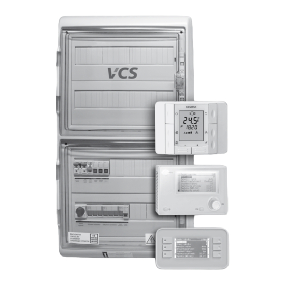
- VCS
- Installation and operating instructions manual
-
Contents
-
Table of Contents
-
Troubleshooting
-
Bookmarks
Quick Links
Řídicí systém pro
vzduchotechnické jednotky
Control units
Summary of Contents for Remak VCS
- Page 1
Řídicí systém pro vzduchotechnické jednotky Control units… -
Page 3: Table Of Contents
The VCS control unit software is the intellectual property Any changes or modifications to individual components of of REMAK a.s. the VCS control unit which could affect its safe and proper functioning are forbidden. VCS control units are manufactured in accordance with…
-
Page 4: Equipment Characteristics
In addition to local VCS controllers, so-called remote control switchboard). Both designs are equipped with transparent can be used. For this control, you need to connect VCS to LAN, doors. Th e controls are situated below these doors. Further, WAN or Internet (For production, the control unit must be the VCS control unit can be produced as a built-in assembly confi gured/ordered with the required functionality).
- Page 5
«Other Controls». External control via one or two non-voltage contacts. Control from parent system When integrating HVAC with the VCS control unit into complex building management systems (BMS), it is also possible to connect to these systems. Subsequently, it is possible to control and monitor the HVAC through them. -
Page 6: Design
Design Design Boxes Indoor VCS control units are built into plastic or sheet metal Th e control system design is based on the selection of re- cabinets with front transparent doors under which controls quired features and on its internal confi guration. Th e design are located.
- Page 7
Any changes or modifi cations to individual components Th e system or device documentation also includes the oper- of the VCS control unit which could aff ect its safe and ating and inspection documentation kept during the device proper functioning are forbidden. - Page 8
The VCS unit installed in steel switchboard boxes can also be Never use abrasive cleaners, cleaners unsuitable for plas- placed directly on the floor. The cables can be run along cable tics or acid or alkaline solutions to clean to unit. -
Page 9: Commissioning
For a general overview of parameters available in the menu applicable local wiring standards and regulations. Before put- and access authorization of users, refer to the chapter VCS ting the unit into operation, an initial wiring inspection must – Parameter Overview and Default Factory Settings. For the be performed in accordance with the national regulations.
- Page 10
Commissioning Location of Control System Sensors Figure 9 – Room sensor installation Inlet Air Temperature Sensor (NS 120) Control and anti–freeze sensors must always be situated behind the heater, respectively cooler – to measure the sup- ply air temperature. They must not be situated in the room. VO antifreeze protection sensor (NS 130R) The return water temperature sensor must be situated in the return water line from the water heater so that it will be… -
Page 11: Control And Protection Functions
Th e fi rst device, i.e. the master controller, terminal resistor setting is performed using the soft ware (ensured by REMAK in the factory). Th e last device terminal resistor setting is performed on the last frequency inverter in the line connection.
- Page 12
Main Control Features safety features are activated. The VCS control unit enables automatic control of the follow- Depending on the failure consequence, the following happens: ing basic functions for air temperature adjustment: The failure is only signalled and safety features are automati- Heating cally activated. - Page 13
If the temperature is Electric heater control in the REMAK unit is doubled – the still falling and drops below 8°C (factory settings), the following heater thermostat failure signal is simultaneously sent to the protection actions will be immediately taken regardless of the controller and auxiliary module. - Page 14
Control and Protection Functions Further re-lighting of the burner is possible once the protec- ence temperature (see the Data Points). The heat pump will be tion time of 150 seconds has elapsed. Modular control of started if the outdoor temperature is higher than the reference the burner is step-less based on the actual requirement (set temperature (with hysteresis of 3 °C). -
Page 15: Additional Operating Modes And Functions
Control units VCS Control and Protection Functions Plate heat exchanger Inverter Unit and Single-Stage Condensing Unit Combination – air-handling unit run-out When cooling is required, the inverter will be switched on In some cases, the run-out will be performed when the first and then the output will be raised to the maximum.
- Page 16
Depending on the technology used, control for the required Auxiliary After-Heating Function with EOS humidity can be performed by the VCS control unit or by an This function is applied when the main heater output is not autonomous control (e.g., integrated into the humidifier). - Page 17
Fan Speed Compensation cooling – fan. So the change in the fan speed is applied first The VCS control unit system enables the pre-set fan speed and then active cooling is applied as the request for cooling is to be adjusted depending on the air temperature, air quality rising. -
Page 18: Control (Hmi-Sg Controller)
/h. This value is then entered the Data Point Settings – Fans). as the maximum range of the sensor in the VCS using HMI. Single-Speed Fan Backups (ON/OFF Control) Note: In AC, the «Max. Air Flow Rate» is stated for the fan as- The backup motor is started if the main motor fails.
- Page 19
It is necessary to set the following parameters of the VCS The operating mode determines which operating state will be control Unit (see List of HMI Data Points): active according to priorities (see Operating Modes). - Page 20
Additional Operating Modes Air-Handling Unit Additional Operating Modes Figure 17 – Operating modes If no operating mode is applied and the time schedule mode is in the Stop state, the air-handling unit can be started from additional operating modes. The user can use the following additional operating modes to start the air-handling unit: Alarm A Night chilling… - Page 21
Control units VCS Additional Operating Modes Night Chilling Termination If the following condition is fulfilled: During night chilling, cold outdoor air is used to cool internal > T rooms of the buildings, thus excess heat accumulated in buildings during the day in summer months is removed. Night… - Page 22
Temperature modes The following parameters are set for the weekly and daily schedules: The VCS control unit system offers the possibility to maintain Start time (= end of previous interval) the controlled room or supply air temperature using two user… - Page 23
5 °C to 40 °C Relative humidity < 85 % Controller Description Warning: To avoid unintentional unit start-up, the master switch must be Table 3 – Function Buttons description switched off and locked when repairing the VCS unit. Button Icon Name Function description… - Page 24
Room temperature in °C digit and numerical) to be set, each for a different access level. (increment 0.1 °C) Factory set default rights to access the VCS control unit using the HMI controller: Room temperature in °F (increment 0.5 °F) Table 5 –… - Page 25
Control units VCS Control (HMI-SG) Data Point List Access and Editing Communication Settings An overview of the structure of parameters accessible via the Once the HMI-SG controller has been connected to the control HMI-SG controller is available in the List of Data Points upon unit, the communication between both devices will be set logging in using the appropriate access right level. - Page 26
HMI-SG controller’s operating mode. System Date and Time Settings Here, the actual VCS system date and time can be set – First Control Unit Start-Up Using HMI-SG Controller these setting are required for correct functioning of the time 1) Press the Plus (T5), Minus (T4) and Mode (T8) buttons schedule programs. - Page 27
Operating Screen (Examples) connected to the device failure detection inputs (incorrect state of the contact) occurs, the VCS control unit will au- After making the HMI-SG controller a service controller, it is tomatically put out an alarm in accordance with an internal possible to change the control unit settings. - Page 28
Use the Program (T3) or Presence (T2) buttons to exit the Quick Menu. Only those values which are included within the given version of the VCS unit are displayed. Briefly press the OK (T6) button to display the values listed… - Page 29
Control units VCS Control (HMI-SG) List of Data Points, Factory Settings Additional Operating Modes and Function Settings Warning: Additional operating modes and functions can be activated The device parameters are structured and made available to in the List of Data Points in the section Settings – Additional users in accordance with their user roles (access levels). -
Page 30: List Of Data Points (Hmi-Sg Controller)
List of Data Points (HMI-SG controller) Menu HMI-SG Factory Settings Parameter Notation Reading Value Meaning code level code level Monitor Temperature °C Temperature in the inlet °C Temperature in the room 1 °C Temperature in the room 2 °C Room unit 1 °C Room unit 2 °C…
- Page 31
Control units VCS List of Data Points (HMI-SG controller) Menu HMI-SG Factory Settings Parameter Notation Reading Value Meaning code level code level 1 on 043 G Water cooler pump state 0 off 1 on 044 G Evaporator cooling stage 1 off… - Page 32
List of Data Points (HMI-SG controller) Menu HMI-SG Factory Settings Parameter Notation Reading Value Meaning code level code level Humidifier state Settings Temperature modes 102 G Comfort — cooling 24.6 °C 104 G Comfort — heating 22.6 °C 106 G Economy — cooling °C 108 G… - Page 33
Control units VCS List of Data Points (HMI-SG controller) Menu HMI-SG Factory Settings Parameter Notation Reading Value Meaning code level code level Inlet fan output St1 setting (a factor of 10) % (m /h, Pa) Inlet fan output St2 setting… - Page 34
List of Data Points (HMI-SG controller) Menu HMI-SG Factory Settings Parameter Notation Reading Value Meaning code level code level + 1 stage + 2 stages + 3 stages + 4 stages 185 A For operating stage St2 — 4 stage — 3 stage — 2 stage — 1 stage… - Page 35
Control units VCS List of Data Points (HMI-SG controller) Menu HMI-SG Factory Settings Parameter Notation Reading Value Meaning code level code level 3 Heating + Cooling 198 S Air quality dependent fan speed compensation 0 No 1 Yes 199 S… - Page 36
List of Data Points (HMI-SG controller) Menu HMI-SG Factory Settings Parameter Notation Reading Value Meaning code level code level 216 A Control signal 0-10 V or 2-10 V, heat exchanger by-pass damper 0 0-10V 1 2-10V 217 A Control signal 0-10 V or 2-10 V, chamber by-pass damper 0 0-10V 1 2-10V Required inlet temperature extra set-point… - Page 37
Control units VCS List of Data Points (HMI-SG controller) Menu HMI-SG Factory Settings Parameter Notation Reading Value Meaning code level code level 274 U Heat pump 0 no 1 variation A 2 variation B 275 U Type of gas heating… - Page 38
List of Data Points (HMI-SG controller) Menu HMI-SG Factory Settings Parameter Notation Reading Value Meaning code level code level 340 U Cooling end point (outdoor temperature) °C 342 U Maximum cooling compensation (speed) -100 100 344 U Heating initial point (outdoor temperature) °C 346 U Heating end point (outdoor temperature) - Page 39
Control units VCS List of Data Points (HMI-SG controller) Menu HMI-SG Factory Settings Parameter Notation Reading Value Meaning code level code level 268 S The signal voltage request of START (Toshiba) Cooling 394 U Outdoor temperature to enable cooling – all versions °C… - Page 40
List of Data Points (HMI-SG controller) Menu HMI-SG Factory Settings Parameter Notation Reading Value Meaning code level code level Mixing Minimum fresh air value setting Minimum fresh air value setting – Comfort mode (pool unit) Minimum fresh air value setting – Economy mode (pool unit) 485 U Minimum fresh air flow rate setting 487 U… - Page 41
Control units VCS List of Data Points (HMI-SG controller) List of Data Points (HMI-SG controller) Menu HMI-SG Factory Settings Parameter Notation Reading Value Meaning code level code level 1 decrease 556 U Compensation display Humidity-dependent mixing damper position compensation 560 A… - Page 42
List of Data Points (HMI-SG controller) Menu HMI-SG Factory Settings Parameter Notation Reading Value Meaning code level code level 678 A Derivative factor — AP from return water 680 A Proportional factor — AP from inlet air 682 A Integrating factor — AP from inlet air 684 A Derivative factor — AP from inlet air 686 A… - Page 43
Control units VCS Menu HMI-SG Factory Settings Parameter Notation Reading Value Meaning code level code level 770 S 771 A Derivative factor Difference between required and inlet temperature monitoring 802 G Maximum difference (±°C) °C 804 G Minimum limit (°C) °C… - Page 44
Menu HMI-SG Factory Settings Parameter Notation Reading Value Meaning code level code level 843 S Number of message repeating during error transfers 844 S Number of error transfers for communication failure evaluation 845 S Frequency inverter 1 address, inlet fan 846 S Frequency inverter 2 address, inlet fan backup or second inlet fan 847 S… - Page 45
Control units VCS Menu HMI-SG Factory Settings Parameter Notation Reading Value Meaning code level code level 898 A Displayed time format — 12h/24h 0 24 h 1 12 h Passwords 899 S Password for Service level access 9999 901 A… -
Page 46: List Of Failures (Hmi-Sg Controller)
List of Failures (HMI-SG controller) Failure Failure Causes Description Reduced humidifi- Reduced humidification output due to the temperature priority (swimming-pool unit) cation output – an information message. 1.) Communication error between control unit and the auxiliary fan frequency inverter (Modbus data bus) – inverter internal error; wrong settings of the frequency inverter data points –…
- Page 47
Control units VCS List of Failures (HMI-SG controller) (continuation) Failure Failure Causes Description Outdoor temperature Information message – The heat pump blocked due to outdoor temperature dependent heat pump blocking Heat pump Heat pump failure – contact Humidification Humidifier failure — contact… - Page 48
List of Failures (HMI-SG controller) (continuation) Failure Failure Causes Description Electric reheating Electric after-heater failure — thermostat Water heater Water heater pump failure — contact pump Water heating ad- ditional antifreeze Electric heating additional PMO — thermostat protection (PMO) Inlet fan Backup inlet fan error — thermo-contact 1.) Backup inlet fan error — flow sensor Inlet fan (air-… -
Page 49: Remak Mobile App
(from v. 4.0.3) in installations / applications where you can use Wi-Fi LAN and / GSM mobile data to connect to the Internet. Mobile applications such as HMI to VCS serve as a user-friendly driver for basic HVAC control — triggering desired mode (+ switching off), setting (user-friendly parameters only) and simple operation overview (feedback).
- Page 50
HMI-DM (HMI-TM) control devices ensure communication Figure 23 – HMI-DM cotroller between the VCS control unit and the user. Th ey are intended for air-handling device control, handling and service. Th e HMI control device can be connected to the POL4xx or POL6xx Info controllers. - Page 51
Control units VCS Control (HMI-DM,HMI-TM controllers) Figure 24 – Installation on a Wall Table 2 – Function Buttons Button Activity Description (Name) — Scrolling the list upwards Press — Increases the parameter value — Hold this button longer than 1.5 s to speed up the… - Page 52
Control (HMI-DM,HMI-TM controllers) Value Settings Display Layout If the description and value of the parameter is highlighted on Figure 26 – LCD isplay the line, the highlighted value can be changed. Turn the knob (or use the Up and Down buttons) to select the line. - Page 53
80 m. Switch the HMI@Web main switch on. If a greater distance between the PC and the VCS control unit controlled by the HMI@Web controller is desired, it will be necessary to use a structured network (Ethernet) including active network elements – see * This cable is not part of delivery. - Page 54
Control (HMI@Web – Connection to PC and LAN/WAN) Connection of the VCS control unit After setting the HMI@Web unit (following the below de- with the HMI@Web controller to the LAN scribed procedure), and when the HMI@Web default address complies with network addressing, it is only necessary to en- Warning able new hardware in the infrastructure administration –… - Page 55
Control units VCS Control (HMI@Web – Connection to PC and LAN/WAN) 3rd Step Setting the Web@HMI for Connection Figure 35 – Log-in screen The Web@HMI controller can be configured from the web interface (the same one which serves for normal operation of the system). - Page 56
Control (HMI@Web – Connection to PC and LAN/WAN) 4th Step: How to Change the HMI@Web Controller IP Then it is necessary to send (plan) the change entry – after Address that, the settings must be finished using the option «Apply + +Reset». - Page 57
IP address via port 80 (http). Other communication ports must be DISABLED to keep the operation secure! REMAK does not bear any responsibility for any misuse of the HMI@Web software (Windows CE) or unauthor- ized penetration of the inner LAN network due to insuf- ficient inner network security. - Page 58
Control (HMI@Web – Connection to PC and LAN/WAN) Internet Settings (Explorer Cookies): Figure 43 – Temporary Files’ Settings (IE) Go to the Internet Explorer menu «Tools» / «Internet Options» >> «Privacy» >> «Advanced» >> «Accept Cookies» (see fig. # 16) Figure 41 –… - Page 59
Control units VCS Control (HMI@Web – Connection to PC and LAN/WAN) Basic HMI@Web Operation HMI@Web Environment Description Settings – Recapitulation Th e Web controller HMI@Web is controlled using the fol- The basic HMI@Web system commissioning settings to lowing buttons: prepare it for operating staff :… -
Page 60: Scada (Supervisory Control And Data Acquisition)
The VCS is equipped with a web server running SCADA VCS. time is assigned with a desired program state (fan speed Just connect the VCS to the LAN / WAN and then use the stages and temperature mode). The program state can be…
- Page 61
Control units VCS List of Data Points (HMI-DM, HMI-TM and HMI@WEB controllers) Menu HMI-DM,HMI-TM a HMI@WEB Factory settings Menu Meaning Value Units Monitor Monitor Current modes Current modes ActStateEquipment Current device state FanStageExtCnt Fan output stage (external control) FanStatus Fan state… -
Page 62: List Of Data Points (Hmi-Dm, Hmi-Tm And Hmi@Web Controller)
List of Data Points (HMI-DM, HMI-TM and HMI@WEB controllers) Menu HMI-DM,HMI-TM a HMI@WEB Factory settings Menu Meaning Value Units StateHumidifier Humidifier state Settings Settings Date Date and Time time TimeValidity System time validity Temp modes Temperature modes Comfort — Heating Comfortable heating 22.6 0 °C…
- Page 63
Control units VCS List of Data Points (HMI-DM, HMI-TM and HMI@WEB controllers) Menu HMI-DM,HMI-TM a HMI@WEB Factory settings Menu Meaning Value Units RundownTmTrans Time transition to 1St speed — two-speed fans BlckHighSpeedFan Outdoor temperature-dependent fan speed interlocking °C ForceStrtTimOn1St Forced fan start-up to 1St speed (TRN – damper output absent) °C… - Page 64
List of Data Points (HMI-DM, HMI-TM and HMI@WEB controllers) Menu HMI-DM,HMI-TM a HMI@WEB Factory settings Menu Meaning Value Units MinRunTm Minimum operating time for heat pump heating 9999 BlckTmAgainStrt Re-heating blocking ActiveHeatPump Heat pump switching on HysOffHeatPump Digital output opening hysteresis AlarmFromOutTmp Information — outdoor temperature dependent heat pump heating blocking StartAnalogVal… - Page 65
Control units VCS List of Data Points (HMI-DM, HMI-TM and HMI@WEB controllers) Menu HMI-DM,HMI-TM a HMI@WEB Factory settings Menu Meaning Value Units CompHEnd Heating end point (outdoor temperature) °C MaxValCompStgHtg Maximum heating compensation (speed) -100 100 ActValComStgFanHtg Current heating speed compensation… - Page 66
List of Data Points (HMI-DM, HMI-TM and HMI@WEB controllers) Menu HMI-DM,HMI-TM a HMI@WEB Factory settings Menu Meaning Value Units GasHeatingMaximalTempFlueGas Maximum temperature of flue gas PropFactor Proportional factor IntegFactor Integrating factor DifferFactor Derivative factor GasHeatingMinimumTempFlueGas Minium temperature of flue gas PropFactor Proportional factor IntegFactor… - Page 67
Control units VCS List of Data Points (HMI-DM, HMI-TM and HMI@WEB controllers) Menu HMI-DM,HMI-TM a HMI@WEB Factory settings Menu Meaning Value Units PropFactor Proportional factor IntegFactor Integrating factor DifferFactor Derivative factor HrecDampCompHumidity Humidity-dependent mixing damper position compensation factors PropFactor Proportional factor… - Page 68
List of Data Points (HMI-DM, HMI-TM and HMI@WEB controllers) Function activation — Max. limit of fresh air ac- ActiveMaxFrshAirDHrec cording to T outdoor (vent. unit) Apply + Reset Reset after configuration of additional modes/functions HMI-SG HMI-SG DisplayedRoomTemp Room temperature display, combined or inlet temperature SetpoitRangeCorr Required value compensation setting +/- °C… - Page 69
Control units VCS List of Data Points (HMI-DM, HMI-TM and HMI@WEB controllers) ActGatewayAdr Current gate address GivenIPAdr IP address input GivenMaskAdr Mask address input GivenGateAdr Gate address input HostName Host name MACAdrress MAC address Web user name HMI@WEB user name:… - Page 70
List of failures (HMI-DM, HMI-TM and HMI@WEB controllers) Failure name Failure Description SupplyTmpSnsr Inlet air temperature sensor RoomTmpSnsr Room air temperature sensor HMI-SG1 Local HMI-SG1 controller HMI-SG2 Local HMI-SG2 controller ReturnAirTmpSnsr Outlet air temperature sensor OutTmpSnsr Outdoor temperature sensor HtgFrstTmpSnsr Return water temperature sensor FrostTmpSnsrHeatEx Antifreeze protection temperature sensor… -
Page 71: List Of Failures (Hmi-Dm, Hmi-Tm And Hmi@Web Controller)
(outlet) air temperature monitoring. Remote Signalling HeatPumpDefrost Heat pump defrosting function The VCS Control unit can optionally be equipped with one or two outputs for remote signalling. Inlet Pressure Unconnected or damaged Depending on the configuration, the following: pressure sensor — inlet fan Only failure (non-potential contact, max.
-
Page 72: Connection To The Master System (Lonworks Standard)
Controller Menu. Thus it can Network Variable: nviPress_Flow03 be determined if the outdoor temperature sensor is connected directly Description: Not used to the VCS control unit or its temperature reading is sent through the Object: SNVT_count communication (LonWorks). Network Variable: nviPress_Flow04…
- Page 73
Control units VCS Connection to the Master System (LonWorks Standard) Active Req. cooling temperature (Comfort) Default: Value: Not used State: Req. heating temperature Remark: The State must be set to «1» to be used (cascade, inlet) for the Value Req. cooling temperature… - Page 74
Connection to the Master System (LonWorks Standard) Network Variable: nvoPress02 Network Variable: nvoPerc09 Description: Not used Description: Air humidity in the inlet Object: SNVT_press_p Object: SNVT_lev_count Network Variable: nvoPress_Flow00 Network Variable: nvoPerc10 Description: Current request for the inlet fan Description: Air humidity in the room Object: SNVT_flow… - Page 75
Control units VCS Connection to the Master System (LonWorks Standard) Cooling DX, 2st >5 Not defined Heat recovery State: Inactive Active Water heating — pump Network Variable: nvoState Electric heating, Stop Description: Alarm classes, Control mode Electric heating, 1st Object:… - Page 76
Connection to the Master System (LonWorks Standard) Pressure differences (air-flow), outlet Remark: *The bit name order can be reversed in some LON software tools Outdoor air humidity Air humidity difference, inlet Network Variable: nvoDO Air humidity difference, room 53 Description: Alarms Dew point Object:… -
Page 77: Connection To The Master System (Modbus Standard)
The Modbus communication protocol works using the Master/ 16-bit for real values (Unsigned Word) Slave principle. The Slave function is used for the VCS control 16-bit for status values (Signed Word) unit communication with the master system. Thus, the VCS…
- Page 78
VCS control system variants at the discretion of REMAK a.s. For example, if the VCS control system (air-handling device) has not been equipped with gas heating, it will not be possible to use these variables. - Page 79
Control units VCS Connection to the Master System (ModBus Standard) Input states (Read) (continuation) Adress Description Values/Units Remarks 1×0027 Supply fan alarm OK*Alarm 1×0028 Supply fan fdbk OK*Alarm 1×0029 Sply fan deviation Passive*Active 1×0030 Exhaust fan alarm OK*Alarm 1×0031 Exhaust fan fdbk… - Page 80
Input states (Read) (continuation) Adress Description Values/Units Remarks 1×0064 1×0065 1×0066 1×0067 1×0070 Filter alarm OK*Alarm 1×0071 Supply filter alarm OK*Alarm 1×0072 Exh filter alarm OK*Alarm 1×0073 Fire alarm OK*Alarm 1×0074 Supply tmp fire alm OK*Alarm 1×0075 Exh tmp fire alarm OK*Alarm 1×0076 Inlet temperature (antifreeze protection) - Page 81
Control units VCS Connection to the Master System (ModBus Standard) Input states (Read) (continuation) Adress Description Values/Units Remarks 1×0101 1×0102 RmUTmp1 °C OK*Alarm 1×0103 RmUTmp2 °C OK*Alarm 1×0104 BrnrFlueTmp °C OK*Alarm 1×0105 PreElHtgTmp °C OK*Alarm Input register (Read) Adress Description… - Page 82
Connection to the Master System (ModBus Standard) Input register (Read) (continuation) Adress Description Values/Units Remarks Bit6 Bit7 Bit8 Bit9 Bit10 Bit11 Bit12 Bit13 Bit14 Bit15 3×0006 Digital inputs (Word 2) 0-65535 0-1 for each bit or counted binary to a decimal number Bit0 Bit1 Bit2… - Page 83
Control units VCS Connection to the Master System (ModBus Standard) Input register (Read) (continuation) Adress Description Values/Units Remarks Bit6 Bit7 Bit8 Bit9 Exhaust fan, running Bit10 Exhaust fan, off Bit11 Bit12 Bit13 Bit14 Bit15 3×0010 Digital outputs (Word 2) 0-65535… - Page 84
Connection to the Master System (ModBus Standard) Input register (Read) (continuation) Adress Description Values/Units Remarks Bit6 Heat pump DO 1 Bit7 Bit8 Extra el heating, off Bit9 Extra el heating, stage 1 Bit10 Bit11 Bit12 Bit13 Request for humidification Bit14 Bit15 3×0012 Digital outputs (Word 4) - Page 85
Control units VCS Connection to the Master System (ModBus Standard) Input register (Read) (continuation) Adress Description Values/Units Remarks Bit7 Exhaust back up Bit8 Cooling Bit9 OverHeat Burner heating Bit10 Heating recovery Bit11 Bit12 Heating recovery frost Bit13 Bit14 Heating recovery damper… - Page 86
Connection to the Master System (ModBus Standard) Input register (Read) (continuation) Adress Description Values/Units Remarks Bit8 Bit9 Bit10 Bit11 Bit12 Bit13 Room unit 1,2 — temperature Bit14 Supply temperature deviation Bit15 Room/Exh temp deviation Alarms (Word 4) 3×0016 0-65535 0-1 for each bit or counted binary to a decimal number Bit0 Supply press/flow deviation… - Page 87
Control units VCS Connection to the Master System (ModBus Standard) Input register (Read) (continuation) Adress Description Values/Units Remarks 10=Stop 11=OverRun 12=StartUp 12=Start 3×0018 Act fan step Off*Stage1*Stage2*St age3*Stage4*Stage5 3×0019 3×0020 Op mode man st/tmp 0-11 Auto*Off*Eco St1*Comf St1*Eco St2*Comf St2*Eco St3*Comf… - Page 88
Connection to the Master System (ModBus Standard) Input register (Read) (continuation) Adress Description Values/Units Remarks 3×0041 Htg pump cmd Off*On 3×0042 El htg outp signal 0 — 100% 3×0043 El heating cmd Off*On 3×0044 Heat pump Cooling 0 — 100% 3×0045 Heat pump 0 — 100%… - Page 89
Control units VCS Connection to the Master System (ModBus Standard) Input register (Read) (continuation) Adress Description Values/Units Remarks 3×0078 3×0079 3×0080 3×0081 3×0082 3×0083 3×0084 Outdoor air humidity — relative %r.H. 3×0085 Outdoor air humidity — absolute `-x.y — +x.y g/kg… - Page 90
Connection to the Master System (ModBus Standard) Input register (Read) (continuation) Adress Description Values/Units Remarks 3×0113 Act exh fan stpt 0-100% (0 — x l/s) 3×0114 3×0115 3×0116 3×0117 3×0120 Hour 3×0121 Minute 3×0122 Second 3×0123 Year 3×0124 Month 3×0125 3×0130 Burner flue temp °C… - Page 91
Control units VCS Connection to the Master System (ModBus Standard) Holding register (Read/Write) [03:H] (continuation) Adress Description Values/Units Remarks Bit13 Bit14 Bit15 Unsigned Word Present value 4×0005 Control state required by BMS Auto*Off*St1*St2*St3* (variant without air temperature St4*St5 conditioning) 4×0006 Device state –… - Page 92
Connection to the Master System (ModBus Standard) Holding register (Read/Write) [03:H] (continuation) Adress Description Values/Units Remarks 4×0033 4×0034 4×0035 4×0036 Sply max limit `-x.y — +x.y °C (factor 10) Higt limit 4×0037 Sply min limit `-x.y — +x.y °C (factor 10) Low limit 4×0039 Set-point of relative humidity — Comfort 0 — x %r.H. - Page 93
Control units VCS Connection to the Master System (ModBus Standard) Holding register (Read/Write) [03:H] (continuation) Adress Description Values/Units Remarks Advanced mode Signed Word PresentValue 4×0070 4×0071 4×0072 4×0073 4×0074 4×0075 4×0076 4×0077 4×0078 4×0079 4×0080 4×0081 4×0082 CaseFlowLimtMinDev °C (factor 10) - Page 94
Connection to the Master System (ModBus Standard) Holding register (Read/Write) [03:H] (continuation) Adress Description Values/Units Remarks 4×0104 4×0105 4×0106 4×0107 4×0108 4×0109 4×0110 4×0111 4×0112 4×0113 4×0114 4×0115 4×0116 Control constants 4×0201 Cooling (factor 100) Gain — Signed Word 4×0202 Cooling 0 — x sec Integral — Unsigned Word… - Page 95
Control units VCS Connection to the Master System (ModBus Standard) Holding register (Read/Write) [03:H] (continuation) Adress Description Values/Units Remarks 4×0223 Electrical heating 0 — x sec Integral — Unsigned Word 4×0224 Electrical heating 0 — x sec Differential — Unsigned Word… - Page 96
Connection to the Master System (ModBus Standard) Holding register (Read/Write) [03:H] (pokračování) Adress Description Values/Units Remarks 4×0260 Exhaust fan 0 — x sec Differential — Unsigned Word 4×0261 Humidification (divider 100) Gain — Signed Word 4×0262 Humidification 0 — x sec Integral — Unsigned Word 4×0263 Humidification… -
Page 97: Connection To The Master System (Bacnet Standard)
BACnet/IP (BMS) restart and other settings of the BACnet server can be carried out through the web page (calling the address set in the VCS The VCS control unit enables integration of the centralized control unit). For detailed information on the BACnet/IP Stand-…
- Page 98
Connection to the Master System (BacNet Standard) List and Description of Basic Data Points ((continuation)) OpModeBmsTimeSt.Swtch BMS control mode (control, master system) OpModeBmsTimeStTmp.Swtch BMS control mode (control, master system) TmpSpv.CoSpvHtg Required value for heating — Comfort TmpSpv.CoSpvClg Required value for cooling — Comfort TmpSpv.EcSpvHtg Required value for heating — Economy TmpSpv.EcSpvClg… -
Page 99: Pool Units — Descriptioon Of Control
Control units VCS POOL UNITS – description of control The VCS also allows the control of air-conditioning units Pro-Vapor Pool Unit (Units without Integrated Heat Pump) designed to ventilate swimming pools (swimming pools, water — The required humidity is achieved by mixing. By supplying parks, rehabilitation complexes with water procedures, etc.).
- Page 100
POOL UNITS – description of control Circulating damper intervention is the same, except for the inlet and outlet dampers, which are controlled according to the humidity Enabled in economy mode heating or dehumidification stage requirement (Economy mode, dehumidification of the 1st 1. -
Page 101: Plc Controller For Compressor Output Control
Control units VCS PLC Controller for Compressor Output Control The selection is made by the relay – KA11 (closed = heating). Then the unit output is controlled by the 0-10V analogue signal. Operation of the unit is indicated by a dry contact, the same way as an error.
- Page 102
PLC Controller for Compressor Output Control Viewing Temperatures and Alarms 2. Using the buttons, select «PASS» and press the SET button to confirm. 3. Using the buttons, enter the numerical code Viewing Temperatures required for the parameter group in question (Level 1 or 1. - Page 103
Control units VCS PLC Controller for Compressor Output Control P-17 Coolant: Used coolant type. Application Version Settings (0= R404A, 1=R22,2=R744, 3 = R290, 4 = R134A, 5 = R407C, 6 = R410A, 7 = R427A, 8 = R507A). One compressor with output P-32 PID HP Udz: PID control upper insensitive zone. - Page 104
PLC Controller for Compressor Output Control Additional Display Views (P-79 parameter) Code Description Outr The sensor is out of the measuring range. An06 Digital compressor discharge temperature. An10 Evaporation temperature An11 Condensation temperature An12 Evaporation pressure An13 Condensation pressure An14 Inlet temperature 1 An15 Inlet temperature 2… - Page 105
Control units VCS PLC Controller for Compressor Output Control Standard Setting Values Code Description Range: Def. P-51 PID Cond Ti 100.0 S-00 Set Te -10.0…10.0°C P-52 PID Cond Td S-01 Set Tc 30.0…90.0°C 63.0 P-53 PID Cond _Utz S-02 Set Cond 20.0…S-01°C… -
Page 106: Electronic Expansion Valve Overheating Controller Ec3-X33
Electronic Expansion Valve Overheating Controller EC3-X33 If the output relay is not used, the user must ensure proper safety regarding power supply breakdown-related failures. Output for EX4 at 24 V DC, max. 0.8 A to 8 valves 0…60 °C 1…25 °C (the longest Teplota okolí…
- Page 107
Control units VCS Electronic Expansion Valve Overheating Controller EC3-X33 Conductor Marking and Purpose Digital input I operation according to com- EX valve connection using terminated cable mands for the compressor/thermostat (A white, B black, C brown, D blue) Operating EX8 (respectively EX7) - Page 108
Electronic Expansion Valve Overheating Controller EC3-X33 ECD-002 Display with Buttons (LED Indicators and Settings) Flashes: The valve opens. On: The valve is open Flashes: The valve closes. Settings: Parameter On: The valve opens. Increases Scrolls On: Command to run Off: N/A Flashes: Exhaust On: Alarm Decreases… - Page 109
Control units VCS Electronic Expansion Valve Overheating Controller EC3-X33 Main Parameters – change if other settings are desired Factory Actual Code Parameter description and options Min. Max. settings settings Password Coolant: 0 = R22 1 = R134a 2 = R507 3 = R404A 4 = R407C 5 = R410A 6 = R124… - Page 110
Electronic Expansion Valve Overheating Controller EC3-X33 ECD-002 Display Installation The ECD-002 display can be connected at any time during operation. The EC2-371 is integrated into a 71 x 29mm panel – see dimensional drawing. Insert the device into the panel (1). The swivel lugs must be inserted into the device edges. - Page 111
Control units VCS Electronic Expansion Valve Overheating Controller EC3-X33 Illustrative Procedure of EC3-X33 and ECD-002 Settings Data display Dimensions EX3-X33 EX3-X33 EX3-X33 ECD-002… -
Page 112: Khd-S1
KHD-S1_ _.R Backup System Wiring Diagram Capacity control 0…10 V Faults Fresh air Unit Alarm Comp Mode: Header Heat/Cool ON/OFF Main switch Failure Filter Filtr (21/28bar) 4…20 mA Relief air Valve in position without power (Cu8 -50) (1.7/2.7bar) 4…20 mA Building wall Legend: Note: The 4-way valve is displayed in the «cooling»…
-
Page 113: Unit Activation
Control units VCS Unit Activation Unit Activation Unicon Air Flow Sensor Settings Sensor operation (Mode) – set to 5.00 Check the correct interconnection of the control unit and air- Adjust measuring range in Pa (in accordance with max. pres- handling unit. Check the motors (frequency inverters) — power sure of the fan).
- Page 114
Unit Activation Coolant Handling To ensure stepless air-flow control using the Unicon sensor and to prevent the fan output cycling, we recommend setting The used HFC type coolants (e.g. R404A, R407C, R410A,…) the frequency inverter start-up and run-down ramps to 180 fall into the category of monitored greenhouse substances s (Danfoss frequency inverter –parameters 3-41 and 3-42). - Page 115
If a failure (incorrect state of the contact) Electric Heater Specialities occurs, the VCS control unit will automatically put out an alarm in accordance with an internal algorithm – indicating The EOS series electric heater design provides safe, reliable the faulty object and in case of severe failures stopping the and long service life. -
Page 116: Troubleshooting
Verify the water cooler circulation pump activation and operation (at active cooling signal above 20% = 2V) Spare parts are not included in the VCS unit delivery. Antifreeze Protection Sensor Failure If any spare parts are needed, they can be ordered from the manufacturer or regional distributor.
-
Page 117: Disposal And Recycling
Printing and language mistakes are reserved. These Installation and Operating Instructions (as a whole or a part) must not be printed or copied without prior written permission from REMAK a. s., Zuberská 2601, Rožnov pod Radhoštěm, Czech Republic These Installation and Operating Instructions are the sole property of REMAK a.
- Page 118
REMAK a.s. Zuberská 2601, 756 61 Rožnov pod Radhoštěm, tel.: +420 571 877 778, fax: +420 571 877 777, email: remak@remak.eu, internet: www.remak.eu…
- Manuals
- Brands
- Remak Manuals
- Control Unit
- VCS
- Installation and operating instructions manual
-
Contents
-
Table of Contents
-
Troubleshooting
-
Bookmarks
Quick Links
Řídicí systém pro
vzduchotechnické jednotky
Control units
Summary of Contents for Remak VCS
- Page 1
Řídicí systém pro vzduchotechnické jednotky Control units… -
Page 3: Table Of Contents
The VCS control unit software is the intellectual property Any changes or modifications to individual components of of REMAK a.s. the VCS control unit which could affect its safe and proper functioning are forbidden. VCS control units are manufactured in accordance with…
-
Page 4: Equipment Characteristics
In addition to local VCS controllers, so-called remote control switchboard). Both designs are equipped with transparent can be used. For this control, you need to connect VCS to LAN, doors. Th e controls are situated below these doors. Further, WAN or Internet (For production, the control unit must be the VCS control unit can be produced as a built-in assembly confi gured/ordered with the required functionality).
- Page 5
«Other Controls». External control via one or two non-voltage contacts. Control from parent system When integrating HVAC with the VCS control unit into complex building management systems (BMS), it is also possible to connect to these systems. Subsequently, it is possible to control and monitor the HVAC through them. -
Page 6: Design
Design Design Boxes Indoor VCS control units are built into plastic or sheet metal Th e control system design is based on the selection of re- cabinets with front transparent doors under which controls quired features and on its internal confi guration. Th e design are located.
- Page 7
Any changes or modifi cations to individual components Th e system or device documentation also includes the oper- of the VCS control unit which could aff ect its safe and ating and inspection documentation kept during the device proper functioning are forbidden. - Page 8
The VCS unit installed in steel switchboard boxes can also be Never use abrasive cleaners, cleaners unsuitable for plas- placed directly on the floor. The cables can be run along cable tics or acid or alkaline solutions to clean to unit. -
Page 9: Commissioning
For a general overview of parameters available in the menu applicable local wiring standards and regulations. Before put- and access authorization of users, refer to the chapter VCS ting the unit into operation, an initial wiring inspection must – Parameter Overview and Default Factory Settings. For the be performed in accordance with the national regulations.
- Page 10
Commissioning Location of Control System Sensors Figure 9 – Room sensor installation Inlet Air Temperature Sensor (NS 120) Control and anti–freeze sensors must always be situated behind the heater, respectively cooler – to measure the sup- ply air temperature. They must not be situated in the room. VO antifreeze protection sensor (NS 130R) The return water temperature sensor must be situated in the return water line from the water heater so that it will be… -
Page 11: Control And Protection Functions
Th e fi rst device, i.e. the master controller, terminal resistor setting is performed using the soft ware (ensured by REMAK in the factory). Th e last device terminal resistor setting is performed on the last frequency inverter in the line connection.
- Page 12
Main Control Features safety features are activated. The VCS control unit enables automatic control of the follow- Depending on the failure consequence, the following happens: ing basic functions for air temperature adjustment: The failure is only signalled and safety features are automati- Heating cally activated. - Page 13
If the temperature is Electric heater control in the REMAK unit is doubled – the still falling and drops below 8°C (factory settings), the following heater thermostat failure signal is simultaneously sent to the protection actions will be immediately taken regardless of the controller and auxiliary module. - Page 14
Control and Protection Functions Further re-lighting of the burner is possible once the protec- ence temperature (see the Data Points). The heat pump will be tion time of 150 seconds has elapsed. Modular control of started if the outdoor temperature is higher than the reference the burner is step-less based on the actual requirement (set temperature (with hysteresis of 3 °C). -
Page 15: Additional Operating Modes And Functions
Control units VCS Control and Protection Functions Plate heat exchanger Inverter Unit and Single-Stage Condensing Unit Combination – air-handling unit run-out When cooling is required, the inverter will be switched on In some cases, the run-out will be performed when the first and then the output will be raised to the maximum.
- Page 16
Depending on the technology used, control for the required Auxiliary After-Heating Function with EOS humidity can be performed by the VCS control unit or by an This function is applied when the main heater output is not autonomous control (e.g., integrated into the humidifier). - Page 17
Fan Speed Compensation cooling – fan. So the change in the fan speed is applied first The VCS control unit system enables the pre-set fan speed and then active cooling is applied as the request for cooling is to be adjusted depending on the air temperature, air quality rising. -
Page 18: Control (Hmi-Sg Controller)
/h. This value is then entered the Data Point Settings – Fans). as the maximum range of the sensor in the VCS using HMI. Single-Speed Fan Backups (ON/OFF Control) Note: In AC, the «Max. Air Flow Rate» is stated for the fan as- The backup motor is started if the main motor fails.
- Page 19
It is necessary to set the following parameters of the VCS The operating mode determines which operating state will be control Unit (see List of HMI Data Points): active according to priorities (see Operating Modes). - Page 20
Additional Operating Modes Air-Handling Unit Additional Operating Modes Figure 17 – Operating modes If no operating mode is applied and the time schedule mode is in the Stop state, the air-handling unit can be started from additional operating modes. The user can use the following additional operating modes to start the air-handling unit: Alarm A Night chilling… - Page 21
Control units VCS Additional Operating Modes Night Chilling Termination If the following condition is fulfilled: During night chilling, cold outdoor air is used to cool internal > T rooms of the buildings, thus excess heat accumulated in buildings during the day in summer months is removed. Night… - Page 22
Temperature modes The following parameters are set for the weekly and daily schedules: The VCS control unit system offers the possibility to maintain Start time (= end of previous interval) the controlled room or supply air temperature using two user… - Page 23
5 °C to 40 °C Relative humidity < 85 % Controller Description Warning: To avoid unintentional unit start-up, the master switch must be Table 3 – Function Buttons description switched off and locked when repairing the VCS unit. Button Icon Name Function description… - Page 24
Room temperature in °C digit and numerical) to be set, each for a different access level. (increment 0.1 °C) Factory set default rights to access the VCS control unit using the HMI controller: Room temperature in °F (increment 0.5 °F) Table 5 –… - Page 25
Control units VCS Control (HMI-SG) Data Point List Access and Editing Communication Settings An overview of the structure of parameters accessible via the Once the HMI-SG controller has been connected to the control HMI-SG controller is available in the List of Data Points upon unit, the communication between both devices will be set logging in using the appropriate access right level. - Page 26
HMI-SG controller’s operating mode. System Date and Time Settings Here, the actual VCS system date and time can be set – First Control Unit Start-Up Using HMI-SG Controller these setting are required for correct functioning of the time 1) Press the Plus (T5), Minus (T4) and Mode (T8) buttons schedule programs. - Page 27
Operating Screen (Examples) connected to the device failure detection inputs (incorrect state of the contact) occurs, the VCS control unit will au- After making the HMI-SG controller a service controller, it is tomatically put out an alarm in accordance with an internal possible to change the control unit settings. - Page 28
Use the Program (T3) or Presence (T2) buttons to exit the Quick Menu. Only those values which are included within the given version of the VCS unit are displayed. Briefly press the OK (T6) button to display the values listed… - Page 29
Control units VCS Control (HMI-SG) List of Data Points, Factory Settings Additional Operating Modes and Function Settings Warning: Additional operating modes and functions can be activated The device parameters are structured and made available to in the List of Data Points in the section Settings – Additional users in accordance with their user roles (access levels). -
Page 30: List Of Data Points (Hmi-Sg Controller)
List of Data Points (HMI-SG controller) Menu HMI-SG Factory Settings Parameter Notation Reading Value Meaning code level code level Monitor Temperature °C Temperature in the inlet °C Temperature in the room 1 °C Temperature in the room 2 °C Room unit 1 °C Room unit 2 °C…
- Page 31
Control units VCS List of Data Points (HMI-SG controller) Menu HMI-SG Factory Settings Parameter Notation Reading Value Meaning code level code level 1 on 043 G Water cooler pump state 0 off 1 on 044 G Evaporator cooling stage 1 off… - Page 32
List of Data Points (HMI-SG controller) Menu HMI-SG Factory Settings Parameter Notation Reading Value Meaning code level code level Humidifier state Settings Temperature modes 102 G Comfort — cooling 24.6 °C 104 G Comfort — heating 22.6 °C 106 G Economy — cooling °C 108 G… - Page 33
Control units VCS List of Data Points (HMI-SG controller) Menu HMI-SG Factory Settings Parameter Notation Reading Value Meaning code level code level Inlet fan output St1 setting (a factor of 10) % (m /h, Pa) Inlet fan output St2 setting… - Page 34
List of Data Points (HMI-SG controller) Menu HMI-SG Factory Settings Parameter Notation Reading Value Meaning code level code level + 1 stage + 2 stages + 3 stages + 4 stages 185 A For operating stage St2 — 4 stage — 3 stage — 2 stage — 1 stage… - Page 35
Control units VCS List of Data Points (HMI-SG controller) Menu HMI-SG Factory Settings Parameter Notation Reading Value Meaning code level code level 3 Heating + Cooling 198 S Air quality dependent fan speed compensation 0 No 1 Yes 199 S… - Page 36
List of Data Points (HMI-SG controller) Menu HMI-SG Factory Settings Parameter Notation Reading Value Meaning code level code level 216 A Control signal 0-10 V or 2-10 V, heat exchanger by-pass damper 0 0-10V 1 2-10V 217 A Control signal 0-10 V or 2-10 V, chamber by-pass damper 0 0-10V 1 2-10V Required inlet temperature extra set-point… - Page 37
Control units VCS List of Data Points (HMI-SG controller) Menu HMI-SG Factory Settings Parameter Notation Reading Value Meaning code level code level 274 U Heat pump 0 no 1 variation A 2 variation B 275 U Type of gas heating… - Page 38
List of Data Points (HMI-SG controller) Menu HMI-SG Factory Settings Parameter Notation Reading Value Meaning code level code level 340 U Cooling end point (outdoor temperature) °C 342 U Maximum cooling compensation (speed) -100 100 344 U Heating initial point (outdoor temperature) °C 346 U Heating end point (outdoor temperature) - Page 39
Control units VCS List of Data Points (HMI-SG controller) Menu HMI-SG Factory Settings Parameter Notation Reading Value Meaning code level code level 268 S The signal voltage request of START (Toshiba) Cooling 394 U Outdoor temperature to enable cooling – all versions °C… - Page 40
List of Data Points (HMI-SG controller) Menu HMI-SG Factory Settings Parameter Notation Reading Value Meaning code level code level Mixing Minimum fresh air value setting Minimum fresh air value setting – Comfort mode (pool unit) Minimum fresh air value setting – Economy mode (pool unit) 485 U Minimum fresh air flow rate setting 487 U… - Page 41
Control units VCS List of Data Points (HMI-SG controller) List of Data Points (HMI-SG controller) Menu HMI-SG Factory Settings Parameter Notation Reading Value Meaning code level code level 1 decrease 556 U Compensation display Humidity-dependent mixing damper position compensation 560 A… - Page 42
List of Data Points (HMI-SG controller) Menu HMI-SG Factory Settings Parameter Notation Reading Value Meaning code level code level 678 A Derivative factor — AP from return water 680 A Proportional factor — AP from inlet air 682 A Integrating factor — AP from inlet air 684 A Derivative factor — AP from inlet air 686 A… - Page 43
Control units VCS Menu HMI-SG Factory Settings Parameter Notation Reading Value Meaning code level code level 770 S 771 A Derivative factor Difference between required and inlet temperature monitoring 802 G Maximum difference (±°C) °C 804 G Minimum limit (°C) °C… - Page 44
Menu HMI-SG Factory Settings Parameter Notation Reading Value Meaning code level code level 843 S Number of message repeating during error transfers 844 S Number of error transfers for communication failure evaluation 845 S Frequency inverter 1 address, inlet fan 846 S Frequency inverter 2 address, inlet fan backup or second inlet fan 847 S… - Page 45
Control units VCS Menu HMI-SG Factory Settings Parameter Notation Reading Value Meaning code level code level 898 A Displayed time format — 12h/24h 0 24 h 1 12 h Passwords 899 S Password for Service level access 9999 901 A… -
Page 46: List Of Failures (Hmi-Sg Controller)
List of Failures (HMI-SG controller) Failure Failure Causes Description Reduced humidifi- Reduced humidification output due to the temperature priority (swimming-pool unit) cation output – an information message. 1.) Communication error between control unit and the auxiliary fan frequency inverter (Modbus data bus) – inverter internal error; wrong settings of the frequency inverter data points –…
- Page 47
Control units VCS List of Failures (HMI-SG controller) (continuation) Failure Failure Causes Description Outdoor temperature Information message – The heat pump blocked due to outdoor temperature dependent heat pump blocking Heat pump Heat pump failure – contact Humidification Humidifier failure — contact… - Page 48
List of Failures (HMI-SG controller) (continuation) Failure Failure Causes Description Electric reheating Electric after-heater failure — thermostat Water heater Water heater pump failure — contact pump Water heating ad- ditional antifreeze Electric heating additional PMO — thermostat protection (PMO) Inlet fan Backup inlet fan error — thermo-contact 1.) Backup inlet fan error — flow sensor Inlet fan (air-… -
Page 49: Remak Mobile App
(from v. 4.0.3) in installations / applications where you can use Wi-Fi LAN and / GSM mobile data to connect to the Internet. Mobile applications such as HMI to VCS serve as a user-friendly driver for basic HVAC control — triggering desired mode (+ switching off), setting (user-friendly parameters only) and simple operation overview (feedback).
- Page 50
HMI-DM (HMI-TM) control devices ensure communication Figure 23 – HMI-DM cotroller between the VCS control unit and the user. Th ey are intended for air-handling device control, handling and service. Th e HMI control device can be connected to the POL4xx or POL6xx Info controllers. - Page 51
Control units VCS Control (HMI-DM,HMI-TM controllers) Figure 24 – Installation on a Wall Table 2 – Function Buttons Button Activity Description (Name) — Scrolling the list upwards Press — Increases the parameter value — Hold this button longer than 1.5 s to speed up the… - Page 52
Control (HMI-DM,HMI-TM controllers) Value Settings Display Layout If the description and value of the parameter is highlighted on Figure 26 – LCD isplay the line, the highlighted value can be changed. Turn the knob (or use the Up and Down buttons) to select the line. - Page 53
80 m. Switch the HMI@Web main switch on. If a greater distance between the PC and the VCS control unit controlled by the HMI@Web controller is desired, it will be necessary to use a structured network (Ethernet) including active network elements – see * This cable is not part of delivery. - Page 54
Control (HMI@Web – Connection to PC and LAN/WAN) Connection of the VCS control unit After setting the HMI@Web unit (following the below de- with the HMI@Web controller to the LAN scribed procedure), and when the HMI@Web default address complies with network addressing, it is only necessary to en- Warning able new hardware in the infrastructure administration –… - Page 55
Control units VCS Control (HMI@Web – Connection to PC and LAN/WAN) 3rd Step Setting the Web@HMI for Connection Figure 35 – Log-in screen The Web@HMI controller can be configured from the web interface (the same one which serves for normal operation of the system). - Page 56
Control (HMI@Web – Connection to PC and LAN/WAN) 4th Step: How to Change the HMI@Web Controller IP Then it is necessary to send (plan) the change entry – after Address that, the settings must be finished using the option «Apply + +Reset». - Page 57
IP address via port 80 (http). Other communication ports must be DISABLED to keep the operation secure! REMAK does not bear any responsibility for any misuse of the HMI@Web software (Windows CE) or unauthor- ized penetration of the inner LAN network due to insuf- ficient inner network security. - Page 58
Control (HMI@Web – Connection to PC and LAN/WAN) Internet Settings (Explorer Cookies): Figure 43 – Temporary Files’ Settings (IE) Go to the Internet Explorer menu «Tools» / «Internet Options» >> «Privacy» >> «Advanced» >> «Accept Cookies» (see fig. # 16) Figure 41 –… - Page 59
Control units VCS Control (HMI@Web – Connection to PC and LAN/WAN) Basic HMI@Web Operation HMI@Web Environment Description Settings – Recapitulation Th e Web controller HMI@Web is controlled using the fol- The basic HMI@Web system commissioning settings to lowing buttons: prepare it for operating staff :… -
Page 60: Scada (Supervisory Control And Data Acquisition)
The VCS is equipped with a web server running SCADA VCS. time is assigned with a desired program state (fan speed Just connect the VCS to the LAN / WAN and then use the stages and temperature mode). The program state can be…
- Page 61
Control units VCS List of Data Points (HMI-DM, HMI-TM and HMI@WEB controllers) Menu HMI-DM,HMI-TM a HMI@WEB Factory settings Menu Meaning Value Units Monitor Monitor Current modes Current modes ActStateEquipment Current device state FanStageExtCnt Fan output stage (external control) FanStatus Fan state… -
Page 62: List Of Data Points (Hmi-Dm, Hmi-Tm And Hmi@Web Controller)
List of Data Points (HMI-DM, HMI-TM and HMI@WEB controllers) Menu HMI-DM,HMI-TM a HMI@WEB Factory settings Menu Meaning Value Units StateHumidifier Humidifier state Settings Settings Date Date and Time time TimeValidity System time validity Temp modes Temperature modes Comfort — Heating Comfortable heating 22.6 0 °C…
- Page 63
Control units VCS List of Data Points (HMI-DM, HMI-TM and HMI@WEB controllers) Menu HMI-DM,HMI-TM a HMI@WEB Factory settings Menu Meaning Value Units RundownTmTrans Time transition to 1St speed — two-speed fans BlckHighSpeedFan Outdoor temperature-dependent fan speed interlocking °C ForceStrtTimOn1St Forced fan start-up to 1St speed (TRN – damper output absent) °C… - Page 64
List of Data Points (HMI-DM, HMI-TM and HMI@WEB controllers) Menu HMI-DM,HMI-TM a HMI@WEB Factory settings Menu Meaning Value Units MinRunTm Minimum operating time for heat pump heating 9999 BlckTmAgainStrt Re-heating blocking ActiveHeatPump Heat pump switching on HysOffHeatPump Digital output opening hysteresis AlarmFromOutTmp Information — outdoor temperature dependent heat pump heating blocking StartAnalogVal… - Page 65
Control units VCS List of Data Points (HMI-DM, HMI-TM and HMI@WEB controllers) Menu HMI-DM,HMI-TM a HMI@WEB Factory settings Menu Meaning Value Units CompHEnd Heating end point (outdoor temperature) °C MaxValCompStgHtg Maximum heating compensation (speed) -100 100 ActValComStgFanHtg Current heating speed compensation… - Page 66
List of Data Points (HMI-DM, HMI-TM and HMI@WEB controllers) Menu HMI-DM,HMI-TM a HMI@WEB Factory settings Menu Meaning Value Units GasHeatingMaximalTempFlueGas Maximum temperature of flue gas PropFactor Proportional factor IntegFactor Integrating factor DifferFactor Derivative factor GasHeatingMinimumTempFlueGas Minium temperature of flue gas PropFactor Proportional factor IntegFactor… - Page 67
Control units VCS List of Data Points (HMI-DM, HMI-TM and HMI@WEB controllers) Menu HMI-DM,HMI-TM a HMI@WEB Factory settings Menu Meaning Value Units PropFactor Proportional factor IntegFactor Integrating factor DifferFactor Derivative factor HrecDampCompHumidity Humidity-dependent mixing damper position compensation factors PropFactor Proportional factor… - Page 68
List of Data Points (HMI-DM, HMI-TM and HMI@WEB controllers) Function activation — Max. limit of fresh air ac- ActiveMaxFrshAirDHrec cording to T outdoor (vent. unit) Apply + Reset Reset after configuration of additional modes/functions HMI-SG HMI-SG DisplayedRoomTemp Room temperature display, combined or inlet temperature SetpoitRangeCorr Required value compensation setting +/- °C… - Page 69
Control units VCS List of Data Points (HMI-DM, HMI-TM and HMI@WEB controllers) ActGatewayAdr Current gate address GivenIPAdr IP address input GivenMaskAdr Mask address input GivenGateAdr Gate address input HostName Host name MACAdrress MAC address Web user name HMI@WEB user name:… - Page 70
List of failures (HMI-DM, HMI-TM and HMI@WEB controllers) Failure name Failure Description SupplyTmpSnsr Inlet air temperature sensor RoomTmpSnsr Room air temperature sensor HMI-SG1 Local HMI-SG1 controller HMI-SG2 Local HMI-SG2 controller ReturnAirTmpSnsr Outlet air temperature sensor OutTmpSnsr Outdoor temperature sensor HtgFrstTmpSnsr Return water temperature sensor FrostTmpSnsrHeatEx Antifreeze protection temperature sensor… -
Page 71: List Of Failures (Hmi-Dm, Hmi-Tm And Hmi@Web Controller)
(outlet) air temperature monitoring. Remote Signalling HeatPumpDefrost Heat pump defrosting function The VCS Control unit can optionally be equipped with one or two outputs for remote signalling. Inlet Pressure Unconnected or damaged Depending on the configuration, the following: pressure sensor — inlet fan Only failure (non-potential contact, max.
-
Page 72: Connection To The Master System (Lonworks Standard)
Controller Menu. Thus it can Network Variable: nviPress_Flow03 be determined if the outdoor temperature sensor is connected directly Description: Not used to the VCS control unit or its temperature reading is sent through the Object: SNVT_count communication (LonWorks). Network Variable: nviPress_Flow04…
- Page 73
Control units VCS Connection to the Master System (LonWorks Standard) Active Req. cooling temperature (Comfort) Default: Value: Not used State: Req. heating temperature Remark: The State must be set to «1» to be used (cascade, inlet) for the Value Req. cooling temperature… - Page 74
Connection to the Master System (LonWorks Standard) Network Variable: nvoPress02 Network Variable: nvoPerc09 Description: Not used Description: Air humidity in the inlet Object: SNVT_press_p Object: SNVT_lev_count Network Variable: nvoPress_Flow00 Network Variable: nvoPerc10 Description: Current request for the inlet fan Description: Air humidity in the room Object: SNVT_flow… - Page 75
Control units VCS Connection to the Master System (LonWorks Standard) Cooling DX, 2st >5 Not defined Heat recovery State: Inactive Active Water heating — pump Network Variable: nvoState Electric heating, Stop Description: Alarm classes, Control mode Electric heating, 1st Object:… - Page 76
Connection to the Master System (LonWorks Standard) Pressure differences (air-flow), outlet Remark: *The bit name order can be reversed in some LON software tools Outdoor air humidity Air humidity difference, inlet Network Variable: nvoDO Air humidity difference, room 53 Description: Alarms Dew point Object:… -
Page 77: Connection To The Master System (Modbus Standard)
The Modbus communication protocol works using the Master/ 16-bit for real values (Unsigned Word) Slave principle. The Slave function is used for the VCS control 16-bit for status values (Signed Word) unit communication with the master system. Thus, the VCS…
- Page 78
VCS control system variants at the discretion of REMAK a.s. For example, if the VCS control system (air-handling device) has not been equipped with gas heating, it will not be possible to use these variables. - Page 79
Control units VCS Connection to the Master System (ModBus Standard) Input states (Read) (continuation) Adress Description Values/Units Remarks 1×0027 Supply fan alarm OK*Alarm 1×0028 Supply fan fdbk OK*Alarm 1×0029 Sply fan deviation Passive*Active 1×0030 Exhaust fan alarm OK*Alarm 1×0031 Exhaust fan fdbk… - Page 80
Input states (Read) (continuation) Adress Description Values/Units Remarks 1×0064 1×0065 1×0066 1×0067 1×0070 Filter alarm OK*Alarm 1×0071 Supply filter alarm OK*Alarm 1×0072 Exh filter alarm OK*Alarm 1×0073 Fire alarm OK*Alarm 1×0074 Supply tmp fire alm OK*Alarm 1×0075 Exh tmp fire alarm OK*Alarm 1×0076 Inlet temperature (antifreeze protection) - Page 81
Control units VCS Connection to the Master System (ModBus Standard) Input states (Read) (continuation) Adress Description Values/Units Remarks 1×0101 1×0102 RmUTmp1 °C OK*Alarm 1×0103 RmUTmp2 °C OK*Alarm 1×0104 BrnrFlueTmp °C OK*Alarm 1×0105 PreElHtgTmp °C OK*Alarm Input register (Read) Adress Description… - Page 82
Connection to the Master System (ModBus Standard) Input register (Read) (continuation) Adress Description Values/Units Remarks Bit6 Bit7 Bit8 Bit9 Bit10 Bit11 Bit12 Bit13 Bit14 Bit15 3×0006 Digital inputs (Word 2) 0-65535 0-1 for each bit or counted binary to a decimal number Bit0 Bit1 Bit2… - Page 83
Control units VCS Connection to the Master System (ModBus Standard) Input register (Read) (continuation) Adress Description Values/Units Remarks Bit6 Bit7 Bit8 Bit9 Exhaust fan, running Bit10 Exhaust fan, off Bit11 Bit12 Bit13 Bit14 Bit15 3×0010 Digital outputs (Word 2) 0-65535… - Page 84
Connection to the Master System (ModBus Standard) Input register (Read) (continuation) Adress Description Values/Units Remarks Bit6 Heat pump DO 1 Bit7 Bit8 Extra el heating, off Bit9 Extra el heating, stage 1 Bit10 Bit11 Bit12 Bit13 Request for humidification Bit14 Bit15 3×0012 Digital outputs (Word 4) - Page 85
Control units VCS Connection to the Master System (ModBus Standard) Input register (Read) (continuation) Adress Description Values/Units Remarks Bit7 Exhaust back up Bit8 Cooling Bit9 OverHeat Burner heating Bit10 Heating recovery Bit11 Bit12 Heating recovery frost Bit13 Bit14 Heating recovery damper… - Page 86
Connection to the Master System (ModBus Standard) Input register (Read) (continuation) Adress Description Values/Units Remarks Bit8 Bit9 Bit10 Bit11 Bit12 Bit13 Room unit 1,2 — temperature Bit14 Supply temperature deviation Bit15 Room/Exh temp deviation Alarms (Word 4) 3×0016 0-65535 0-1 for each bit or counted binary to a decimal number Bit0 Supply press/flow deviation… - Page 87
Control units VCS Connection to the Master System (ModBus Standard) Input register (Read) (continuation) Adress Description Values/Units Remarks 10=Stop 11=OverRun 12=StartUp 12=Start 3×0018 Act fan step Off*Stage1*Stage2*St age3*Stage4*Stage5 3×0019 3×0020 Op mode man st/tmp 0-11 Auto*Off*Eco St1*Comf St1*Eco St2*Comf St2*Eco St3*Comf… - Page 88
Connection to the Master System (ModBus Standard) Input register (Read) (continuation) Adress Description Values/Units Remarks 3×0041 Htg pump cmd Off*On 3×0042 El htg outp signal 0 — 100% 3×0043 El heating cmd Off*On 3×0044 Heat pump Cooling 0 — 100% 3×0045 Heat pump 0 — 100%… - Page 89
Control units VCS Connection to the Master System (ModBus Standard) Input register (Read) (continuation) Adress Description Values/Units Remarks 3×0078 3×0079 3×0080 3×0081 3×0082 3×0083 3×0084 Outdoor air humidity — relative %r.H. 3×0085 Outdoor air humidity — absolute `-x.y — +x.y g/kg… - Page 90
Connection to the Master System (ModBus Standard) Input register (Read) (continuation) Adress Description Values/Units Remarks 3×0113 Act exh fan stpt 0-100% (0 — x l/s) 3×0114 3×0115 3×0116 3×0117 3×0120 Hour 3×0121 Minute 3×0122 Second 3×0123 Year 3×0124 Month 3×0125 3×0130 Burner flue temp °C… - Page 91
Control units VCS Connection to the Master System (ModBus Standard) Holding register (Read/Write) [03:H] (continuation) Adress Description Values/Units Remarks Bit13 Bit14 Bit15 Unsigned Word Present value 4×0005 Control state required by BMS Auto*Off*St1*St2*St3* (variant without air temperature St4*St5 conditioning) 4×0006 Device state –… - Page 92
Connection to the Master System (ModBus Standard) Holding register (Read/Write) [03:H] (continuation) Adress Description Values/Units Remarks 4×0033 4×0034 4×0035 4×0036 Sply max limit `-x.y — +x.y °C (factor 10) Higt limit 4×0037 Sply min limit `-x.y — +x.y °C (factor 10) Low limit 4×0039 Set-point of relative humidity — Comfort 0 — x %r.H. - Page 93
Control units VCS Connection to the Master System (ModBus Standard) Holding register (Read/Write) [03:H] (continuation) Adress Description Values/Units Remarks Advanced mode Signed Word PresentValue 4×0070 4×0071 4×0072 4×0073 4×0074 4×0075 4×0076 4×0077 4×0078 4×0079 4×0080 4×0081 4×0082 CaseFlowLimtMinDev °C (factor 10) - Page 94
Connection to the Master System (ModBus Standard) Holding register (Read/Write) [03:H] (continuation) Adress Description Values/Units Remarks 4×0104 4×0105 4×0106 4×0107 4×0108 4×0109 4×0110 4×0111 4×0112 4×0113 4×0114 4×0115 4×0116 Control constants 4×0201 Cooling (factor 100) Gain — Signed Word 4×0202 Cooling 0 — x sec Integral — Unsigned Word… - Page 95
Control units VCS Connection to the Master System (ModBus Standard) Holding register (Read/Write) [03:H] (continuation) Adress Description Values/Units Remarks 4×0223 Electrical heating 0 — x sec Integral — Unsigned Word 4×0224 Electrical heating 0 — x sec Differential — Unsigned Word… - Page 96
Connection to the Master System (ModBus Standard) Holding register (Read/Write) [03:H] (pokračování) Adress Description Values/Units Remarks 4×0260 Exhaust fan 0 — x sec Differential — Unsigned Word 4×0261 Humidification (divider 100) Gain — Signed Word 4×0262 Humidification 0 — x sec Integral — Unsigned Word 4×0263 Humidification… -
Page 97: Connection To The Master System (Bacnet Standard)
BACnet/IP (BMS) restart and other settings of the BACnet server can be carried out through the web page (calling the address set in the VCS The VCS control unit enables integration of the centralized control unit). For detailed information on the BACnet/IP Stand-…
- Page 98
Connection to the Master System (BacNet Standard) List and Description of Basic Data Points ((continuation)) OpModeBmsTimeSt.Swtch BMS control mode (control, master system) OpModeBmsTimeStTmp.Swtch BMS control mode (control, master system) TmpSpv.CoSpvHtg Required value for heating — Comfort TmpSpv.CoSpvClg Required value for cooling — Comfort TmpSpv.EcSpvHtg Required value for heating — Economy TmpSpv.EcSpvClg… -
Page 99: Pool Units — Descriptioon Of Control
Control units VCS POOL UNITS – description of control The VCS also allows the control of air-conditioning units Pro-Vapor Pool Unit (Units without Integrated Heat Pump) designed to ventilate swimming pools (swimming pools, water — The required humidity is achieved by mixing. By supplying parks, rehabilitation complexes with water procedures, etc.).
- Page 100
POOL UNITS – description of control Circulating damper intervention is the same, except for the inlet and outlet dampers, which are controlled according to the humidity Enabled in economy mode heating or dehumidification stage requirement (Economy mode, dehumidification of the 1st 1. -
Page 101: Plc Controller For Compressor Output Control
Control units VCS PLC Controller for Compressor Output Control The selection is made by the relay – KA11 (closed = heating). Then the unit output is controlled by the 0-10V analogue signal. Operation of the unit is indicated by a dry contact, the same way as an error.
- Page 102
PLC Controller for Compressor Output Control Viewing Temperatures and Alarms 2. Using the buttons, select «PASS» and press the SET button to confirm. 3. Using the buttons, enter the numerical code Viewing Temperatures required for the parameter group in question (Level 1 or 1. - Page 103
Control units VCS PLC Controller for Compressor Output Control P-17 Coolant: Used coolant type. Application Version Settings (0= R404A, 1=R22,2=R744, 3 = R290, 4 = R134A, 5 = R407C, 6 = R410A, 7 = R427A, 8 = R507A). One compressor with output P-32 PID HP Udz: PID control upper insensitive zone. - Page 104
PLC Controller for Compressor Output Control Additional Display Views (P-79 parameter) Code Description Outr The sensor is out of the measuring range. An06 Digital compressor discharge temperature. An10 Evaporation temperature An11 Condensation temperature An12 Evaporation pressure An13 Condensation pressure An14 Inlet temperature 1 An15 Inlet temperature 2… - Page 105
Control units VCS PLC Controller for Compressor Output Control Standard Setting Values Code Description Range: Def. P-51 PID Cond Ti 100.0 S-00 Set Te -10.0…10.0°C P-52 PID Cond Td S-01 Set Tc 30.0…90.0°C 63.0 P-53 PID Cond _Utz S-02 Set Cond 20.0…S-01°C… -
Page 106: Electronic Expansion Valve Overheating Controller Ec3-X33
Electronic Expansion Valve Overheating Controller EC3-X33 If the output relay is not used, the user must ensure proper safety regarding power supply breakdown-related failures. Output for EX4 at 24 V DC, max. 0.8 A to 8 valves 0…60 °C 1…25 °C (the longest Teplota okolí…
- Page 107
Control units VCS Electronic Expansion Valve Overheating Controller EC3-X33 Conductor Marking and Purpose Digital input I operation according to com- EX valve connection using terminated cable mands for the compressor/thermostat (A white, B black, C brown, D blue) Operating EX8 (respectively EX7) - Page 108
Electronic Expansion Valve Overheating Controller EC3-X33 ECD-002 Display with Buttons (LED Indicators and Settings) Flashes: The valve opens. On: The valve is open Flashes: The valve closes. Settings: Parameter On: The valve opens. Increases Scrolls On: Command to run Off: N/A Flashes: Exhaust On: Alarm Decreases… - Page 109
Control units VCS Electronic Expansion Valve Overheating Controller EC3-X33 Main Parameters – change if other settings are desired Factory Actual Code Parameter description and options Min. Max. settings settings Password Coolant: 0 = R22 1 = R134a 2 = R507 3 = R404A 4 = R407C 5 = R410A 6 = R124… - Page 110
Electronic Expansion Valve Overheating Controller EC3-X33 ECD-002 Display Installation The ECD-002 display can be connected at any time during operation. The EC2-371 is integrated into a 71 x 29mm panel – see dimensional drawing. Insert the device into the panel (1). The swivel lugs must be inserted into the device edges. - Page 111
Control units VCS Electronic Expansion Valve Overheating Controller EC3-X33 Illustrative Procedure of EC3-X33 and ECD-002 Settings Data display Dimensions EX3-X33 EX3-X33 EX3-X33 ECD-002… -
Page 112: Khd-S1
KHD-S1_ _.R Backup System Wiring Diagram Capacity control 0…10 V Faults Fresh air Unit Alarm Comp Mode: Header Heat/Cool ON/OFF Main switch Failure Filter Filtr (21/28bar) 4…20 mA Relief air Valve in position without power (Cu8 -50) (1.7/2.7bar) 4…20 mA Building wall Legend: Note: The 4-way valve is displayed in the «cooling»…
-
Page 113: Unit Activation
Control units VCS Unit Activation Unit Activation Unicon Air Flow Sensor Settings Sensor operation (Mode) – set to 5.00 Check the correct interconnection of the control unit and air- Adjust measuring range in Pa (in accordance with max. pres- handling unit. Check the motors (frequency inverters) — power sure of the fan).
- Page 114
Unit Activation Coolant Handling To ensure stepless air-flow control using the Unicon sensor and to prevent the fan output cycling, we recommend setting The used HFC type coolants (e.g. R404A, R407C, R410A,…) the frequency inverter start-up and run-down ramps to 180 fall into the category of monitored greenhouse substances s (Danfoss frequency inverter –parameters 3-41 and 3-42). - Page 115
If a failure (incorrect state of the contact) Electric Heater Specialities occurs, the VCS control unit will automatically put out an alarm in accordance with an internal algorithm – indicating The EOS series electric heater design provides safe, reliable the faulty object and in case of severe failures stopping the and long service life. -
Page 116: Troubleshooting
Verify the water cooler circulation pump activation and operation (at active cooling signal above 20% = 2V) Spare parts are not included in the VCS unit delivery. Antifreeze Protection Sensor Failure If any spare parts are needed, they can be ordered from the manufacturer or regional distributor.
-
Page 117: Disposal And Recycling
Printing and language mistakes are reserved. These Installation and Operating Instructions (as a whole or a part) must not be printed or copied without prior written permission from REMAK a. s., Zuberská 2601, Rožnov pod Radhoštěm, Czech Republic These Installation and Operating Instructions are the sole property of REMAK a.
- Page 118
REMAK a.s. Zuberská 2601, 756 61 Rožnov pod Radhoštěm, tel.: +420 571 877 778, fax: +420 571 877 777, email: remak@remak.eu, internet: www.remak.eu…
#1
![]()
inovator
-

- Пользователи
-
- 3 сообщений
Новичок


0
Отправлено 04 Июнь 2012, 19:28
Здравствуйте уважаемые. Ранее не работал с автоматикой Ремак и вот сбылось … . Шкаф VCB показывает аварии «акустический сигнал» и «проток воздуха». Перепробовал различные комбинации с диф.манометром фильтра, ничего не помогло. На счёт «акустический сигнал», вообще теряюсь в догадках. Ни в каких мануалах, это даже не упоминается. Может кто сталкивался с онными проблемами ?
- Наверх
#2
![]()
Boriska
Boriska
10
- из: М.о. Балашиха
Отправлено 04 Июнь 2012, 21:50
А ты поставщику позвонить не пробовал ?
Служба тех. поддержки у них работает вполне нормально …
- Наверх
#3
![]()
Сергей
Отправлено 15 Июнь 2012, 15:11
Цитата(inovator @ 04.06.2012, 19:28)
Здравствуйте уважаемые. Ранее не работал с автоматикой Ремак и вот сбылось … . Шкаф VCB показывает аварии «акустический сигнал» и «проток воздуха». Перепробовал различные комбинации с диф.манометром фильтра, ничего не помогло. На счёт «акустический сигнал», вообще теряюсь в догадках. Ни в каких мануалах, это даже не упоминается. Может кто сталкивался с онными проблемами ?
Система уже работала или это выявилось при первом запуске? Частотник на вентилятор стоит?
Что касается акустического сигнала, то, на сколько я помню, его надо просто распознать, когда ошибка по потоку будет устранена и он пропадет.
- Наверх
#4
![]()
inovator
inovator
-
- Пользователи
-
- 3 сообщений
Новичок
0
Отправлено 17 Июнь 2012, 06:07
Цитата(Сергей @ 15.06.2012, 15:11)
Система уже работала или это выявилось при первом запуске? Частотник на вентилятор стоит?
Что касается акустического сигнала, то, на сколько я помню, его надо просто распознать, когда ошибка по потоку будет устранена и он пропадет.
Вы правы, это выявилось при первом запуске. И как выяснилось, «акустический сигнал» — это индикация любой аварии (зачем ?). А «ошибка потока», выдается как диф.манометром, так и выходным реле часстотника, которое попросту не работало.
- Наверх
#5
![]()
Сергей
Отправлено 18 Июнь 2012, 09:02
Цитата(inovator @ 17.06.2012, 6:07)
Вы правы, это выявилось при первом запуске. И как выяснилось, «акустический сигнал» — это индикация любой аварии (зачем ?). А «ошибка потока», выдается как диф.манометром, так и выходным реле часстотника, которое попросту не работало.
Так это был именно косяк в частотнике или монтажники не совсем правильно все скоммутировали?
Ну да, там последовательно соединены два контакта, один — реле в частотнике (клеммы Е2.А/Е2.А), второй нормально разомкнутый контакт дифа(клеммы Е2.1/Е2.1). И приходит все это на клеммы DI 3 контроллера RWD.
Давненько не возился с VCBшками, но, насколько я помню, акустический сигнал мождно найти в неисправностях и распознать, нажать «ОК» и он заткнется и не будет выносить мозг службе эксплуатации, пока сервисники, откладывают запланированные дела и гЭроически выдвигаются на объект 
- Наверх
#6
![]()
inovator
inovator
-
- Пользователи
-
- 3 сообщений
Новичок
0
Отправлено 18 Июнь 2012, 23:10
Цитата(Сергей @ 18.06.2012, 9:02)
Так это был именно косяк в частотнике или монтажники не совсем правильно все скоммутировали?
Ну да, там последовательно соединены два контакта, один — реле в частотнике (клеммы Е2.А/Е2.А), второй нормально разомкнутый контакт дифа(клеммы Е2.1/Е2.1). И приходит все это на клеммы DI 3 контроллера RWD.
Давненько не возился с VCBшками, но, насколько я помню, акустический сигнал мождно найти в неисправностях и распознать, нажать «ОК» и он заткнется и не будет выносить мозг службе эксплуатации, пока сервисники, откладывают запланированные дела и гЭроически выдвигаются на объект
Это был косяк частотника под именем VAGON. А на счёт » акустический сигнал» , я так и не понял зачем онный параметр, выводиться при любой аварии, вообще ?! Показать что в системе авария ? Так это и без него видно. А на счёт продукции VCB — связываться с ней больше не хочу ! Тупая, неуправляемая жестянка (ИМХО).
- Наверх
Задать вопрос специалисту по ремонту и обслуживанию REMAK
Техническое обслуживание систем вентиляции и правила установки оборудования фирмы REMAK:
Для достижения нормального срока службы оборудования необходимо обеспечить соблюдение требований соответствующих технических стандартов, инструкций, указанных в наших технических записках и в Руководстве по эксплуатации и техническому обслуживанию, а также проведение регулярного технического обслуживания. Не допускать эксплуатацию агрегата в ненормальном рабочем состоянии.
Настоящий документ не является исчерпывающим. Для получения дополнительной, более подробной информации воспользуйтесь Руководством по монтажу, эксплуатации и техническому обслуживанию. Этот раздел содержит перечень некоторых основных рекомендаций и технических норм для правильной установки и обслуживания оборудования.
- VВсе наши агрегаты перевозятся на грузовом автотранспорте, погрузка на который осуществляется с помощью мостового крана. Для предотвращения повреждений компрессоров при транспортировке или в ходе монтажа, агрегаты не должны быть наклонены, не должны укладываться на одно сторону или в перевернутом положении. Поэтому необходимо, чтобы при перемещении в ходе монтажа или при транспортировке агрегаты всегда находились в рабочем положении.
- Наши агрегаты сконструированы для поднимания с помощью штанг, вставленных в соответствующие отверстия в элементах несущей конструкции агрегата. Для предотвращения контакта подъёмных тросов и цепей с установкой и повреждения ее конструкции рекомендуется использовать крестовину или распорные штанги. Поэтому рекомендуется строго соблюдать инструкцию по подъёму оборудования, поставленную вместе с установкой, в которой находится более подробная дополнительная информация.
- Поверхность, на которую установка будет поставлена, должна быть ровной и с достаточной несущей способностью, чтобы выдержала нагрузки от агрегата (см. чертёж весовых нагрузок, поставленный вместе с установкой, и техническую записку).
- Для глушения передачи вибраций на конструкцию, на которую агрегат установлен, необходимо во всех опорных точках использовать гасители вибраций. У агрегатов, которые будут поставлены на землю, рекомендуется использовать резиновые гасители вибраций, а для установок, располагаемых на крыше, рекомендуются пружинные амортизаторы.
- Для обеспечения правильного движения потока воздуха и свободного доступа для проведения технического обслуживания вокруг оборудования должно быть оставлено достаточно свободного места – см. спецификацию в технической записке к каждой установке. В случае расположения двух агрегатов возле себя, причем змеевиками друг к другу, расстояния, указанные в технической записке, необходимо удвоить.
Внимание! Несоблюдение этого технического правила автоматически несет за собой потерю гарантии и выплывающего из нее права на бесплатный ремонт, несмотря на то, по какой причине возникла неисправность.
- Перед чисткой агрегата, должны быть прочищены все трубопроводы рабочего оборудования. Если для прочистки труб необходимо применить химические вещества, то в этом случае испаритель необходимо перекрыть и обойти для предотвращения возможного повреждения медных трубок.
- При наличии загрязнений и/или агрессивного конденсата воды перед конденсатором холодильного агрегата должен быть установлен промежуточный теплообменник «вода-вода».
- Выполнение вышеупомянутых инструкций по монтажу является необходимым условием для признания действия гарантии и выплывающих из нее обязательств.
- Объём воды.
Для правильной работы агрегата необходим определённый объём воды, который рассчитывается по следующим формулам:

P = производительность по холоду холодильного агрегата и по теплу теплового насоса в кВт.
_t = разность температур, заданная микропроцессором в °C.
V = полезный объём воды, выраженный в кубических метрах (м3).
Использование неподготовленной или плохо подготовленной воды может вызвать образование накипи, ржавчины, эрозии, водорослей или осадка.
В случае необходимости следует привлечь специализированную компанию по очистке и водообработке, чтобы выбрать наиболее подходящий способ подготовки воды.
На любое повреждение, возникшее в результате коррозии, эрозии или преждевременного износа, причиной которых была плохая водоподготовка, гарантия не распространяется.
&
Агрегаты ‘воздух-воздух’.
- Vzduchotechnická potrubí musí být připojena na sání výtlačných ventilátorů, jejichž pokles zatížení musí být v souladu s projektovanými hodnotami jednotek.Воздуховоды подсоединены на всасывание вытяжных вентиляторов, понижение загрузки которых должно быть в соответствии с проектными величинами установок.
- Подсоединение этих воздуховодов к агрегатам должно осуществляться посредством антивибрационных вставок из непроницаемой ткани. Это имеет принципиальное значение для предотвращения передачи вибраций от агрегатов на воздуховоды.
- Особое внимание надо уделять проектированию и монтажу всасывающего трубопровода и напорного воздуховода для змеевиков теплообменников так, чтобы не возникали препятствия, ограничивающие пропускную способность потока воздуха. Низкий расход воздуха, протекающего через змеевик теплообменника, становится причиной ненормальной работы агрегата и его окончательного выхода из строя.
Эти трубопроводы должны быть максимально короткими и по возможности проложены по прямой трассе.
- Защитные решетки, установленные на всасывании наружного воздуха, должны быть конструированы так, чтобы создавали минимальное сопротивление потоку воздуха.
- Должны быть приняты все необходимые меры для предотвращения смешивания выбрасываемого и рекуперативного (возвратного) воздухa (кратковременное взаимное соединение контуров воздуховодов).
- Воздух для теплообменника не должен всасываться вблизи источников тепла и/или загрязнений.
- За решетками на выхлопах или на всасывании должны быть установлены сетки для предотвращения проникания птиц и мышей в воздуховоды вентиляционной системы.
Агрегаты ‘воздух-воздух’ и кровельные агрегаты.
- Все наружные и внутренние агрегаты (разделенная система охлаждения кондиционирования) оснащены сливными поддонами, расположенными под змеевиками теплообменников.
- Сливной трубопровод должен быть такого же диаметра (или больше), как и присоединительный патрубок агрегата, который, как правило, оснащен внутренней резьбой 1″, причём уклон трубопровода должен быть примерно 3 % в сторону потока жидкости.
- На трубопроводе должен быть установлен сифон, высота которого должна соответствовать высоте напора вентилятора, что не позволяет вентилятору создавать разрежение, которое препятствовало бы нормальному отведению конденсата.
Кровельные агрегаты.
- Между опорами вентиляционных воздуховодов, подсоединенных к кровельным агрегатам, и самими трубами следует вставлять звукоизоляционный материал для предотвращения передачи вибраций.
- Присоединительный трубопровод испарителя должен быть надлежащим способом подперт так, чтобы его вес не переносился на рабочее оборудование.
- Гидравлический контур испарителя должен быть оснащен следующим оборудованием:
- Два манометра с соответствующей впускной и выходной шкалой.
- Две антивибрационные соединительные вставки, предотвращающие передачу вибраций от агрегата на водопровод и позволяющие производить независимое отключение агрегата.
- Отсекающий клапан (на входе в устройство)
- Калибровочный клапан (на входе в агрегат)
- Два термометра (на входе и выходе).
- Циркуляционный насос.
- Предохранительный клапан бака.
- Автоматический сливной клапан бака.
- Расширительный бак.
- Фильтр на вводе, расположенный как можно ближе к фланцу испарителя.
- Расходомер.
Вышеупомянутые инструкции по монтажу для типовой серии RED LINE обуславливают признание действия гарантии; при несоблюдении этих инструкций действие гарантии и выплывающих из нее обязательств прекращается.
Инструкции, касающиеся антивибрационных соединительных элементов, устанавливаемых на трубопроводах, фильтра на входе в испаритель и расходомера обуславливают признание действия гарантии на к типовую серию BLUE LINE; при несоблюдении этих инструкций действие гарантии и выплывающих из нее обязательств прекращается.
- Разъемные компрессоры могут быть установлены на пружинных виброгасителях.
В этом случае надо устранить фиксаторы (деревянные колодки), блокирующие основание компрессора в соответствии с инструкциями на щитке, закрепленном на корпусе компрессора.
- Агрегат необходимо установить на расстоянии минимально 6 м от всех отражающих звук поверхностей, что предотвратит увеличение уровня шума примерно на 3 дБ (A) от всех отражающих звук поверхностей.
- Агрегат установить так, чтобы к местам чувствительным к шуму он был повернут боковыми стенками, излучающими минимальный уровень шума. В некоторых случаях с помощью простого приспособления можно избежать необходимости использования оборудования для подавления шума, как например противошумовые щиты.
Если агрегат установлен на крыше:
- Помещения, расположенные под ним, необходимо изолировать кровлей с высокой степенью звуконепроницаемости.
- Соответствующим способом должна быть усилена опорная конструкция, причем так, чтобы вибрации не переносились во внутрь здания.
- Установите агрегат на пружинные амортизаторы вибраций.
- Опорную конструкцию агрегата отделить от несущей конструкции здания, используя для этого соответствующие упругие соединительные элементы.
- Гидравлические трубы и электрические кабели агрегата необходимо отделить при помощи гибких соединений. Если агрегат установлен на двутавровых траверсах, высотой более 20 см, то по периметру между агрегатом и кровлей необходимо уложить подходящие панели.
Это позволит значительно снизить эффект «резонирующего шкафа», который в противном случае мог бы способствовать повышению уровня шума в просторе под агрегатом на 15 дБ (А).
ТЕХНИЧЕСКОЕ ОБСЛУЖИВАНИЕ
В этой главе мы считаем важным припомнить всем пользователям и конструкторам рабочего оборудования основной концепт, соблюдение которого обуслaвливает правильное использование агрегата и длительный срок службы.
Наряду с соблюдением стандартных гарантийных условий, то есть регулярного проведения текущего технического обслуживания квалифицированными, специально обученными техниками в течение двенадцати месяцев гарантийного срока, это также профилактика дефектов и неисправностей в ходе эксплуатации. Проблемы этого рода не только в том, что они не включены в гарантию, а в том, что они могут повредить компоненты, на которые не распространяется гарантия из-за отсутствия соответствующей и надлежащей программы (плана-графика) работ по техническому обслуживанию.
Выполнение работ по техническому обслуживанию является важным для содержания агрегата в хорошем рабочем состоянии, что касается как его работоспособности, так и энергетической эффективности.
Каждый агрегат имеет свой журнал обслуживания, в котором пользователь или лицо, ответственное за техническое обслуживание агрегата, должны отмечать все подробности о проводимом техническом обслуживании и тем самым сохранять хронологическую документацию эксплуатации агрегата.
Если эта информация в журнал техобслуживания отсутствует, то это может рассматриваться как доказательство недостаточного технического обслуживания.
Поэтому мы рекомендуем заключить договор на техническое обслуживание с Сервисной службой для обеспечения регулярного технического обслуживания силами квалифицированным в этой специализации работником.
Это даст возможность своевременного выявления эксплуатационных недостатков, и свести к минимуму риск возникновения серьёзных неполадок.
Компания REMAK всегда готова провести анализ и оказать консалтинговые услуги, что касается составления программ и спецификаций по профилактическому техническому обслуживанию.
Однако следует не забывать о том, что все тепловые насосы должны иметь рабочий журнал для зимней эксплуатации.
Этот журнал должен выдать завод-изготовитель или кто-либо другой, кто берёт на себя ответственность за эксплуатацию и техническое обслуживание рабочего оборудования.
“»Отопительные агрегаты, которые отапливают помещения в зимнее время с полным или частичным использованием машинного оборудования и систем не на базе теплогенераторов, установок и систем с тепловыми насосами (…), должны вестись «Эксплуатационный журнал системы», выданный поставщиком рабочего оборудования или лицом, ответственным за эксплуатацию и техобслуживание существующего рабочего оборудование. Этот журнал должен содержать не только описание самого рабочего оборудования, но также и перечень элементов, подлегающих контролю, пределы допустимости этих элементов согласно действующему законодательству, а также интервалы контрольных осмотров (…).»
Ниже приводится краткое резюме некоторых важных рекомендаций и технических инструкций по обеспечению надлежащего технического обслуживания:
- Каждый месяц должна производиться подтяжка всех электрических соединений, особенно это касается подключений контакторов и ввода электроэнергии.
- Регулярно контролировать и чистить на приточном водопроводе испарителя в зависимости от вида источника воды и от срока службы водопроводной системы.
- Минимально раз в год проводить визуальный осмотр состояния напорного оборудований, особенно необходимо контролировать, если на поверхности не появляются признаки коррозии, если не коррозируются другие детали и, если не проявляются другие видимые дефекты.
- Если оксидация и коррозия не будут своевременно обнаружены и надлежащим способом остановлены, то может произойти ослабление стен с последующим снижением их механической прочности.
- Минимально два раза в год проводить контроль контура охлаждения, при этом необходимо отстранить любые обнаруженные утечки ХФУ (фреона).
- Минимально два раза в год, всегда перед началом летнего и зимнего сезона, прочистить змеевики теплообменников раствором специального препарата для удаления накипи и осадков, снижающих эффективность теплообмена.
- У агрегатов типа «вода-вода» один раз за полгода (6 месяцев) контролировать эффективность работы и чистоту теплообменника и конденсатора. Испаритель необходимо прочищать с использованием раствора специального препарата от удаления осаждений, запрещается использовать химические чистящие средства. Трубки конденсатора можно протирать тряпкой.
- Каждый месяц определять потребление (расход) электроэнергии у компрессоров и электродвигателей вентиляторов, измеренное потребление эл. энергии сравнить с параметрами, указанными на заводском щитке, определить все величины, которые не соответствуют данным, уведенным на заводском щитке.
- Контролировать загруженность хладагента, что необходимо производить измерением перегрева или переохлаждения. При помощи оборудования по обнаружению утечек проверить, если в оборудовании нет утечек фреона.
- Один раз за 6 месяцев проверить состояние механических компонентов с подвижными частями (вентиляторы, насосы).
- Один раз за 6 месяцев делать лабораторный анализ кислотности масла в контуре охлаждения. Масло и соответствующие фильтры всегда должны быть заменены после 5000 отработанных часов или через каждых 2 года.
- После каждых 10000 отработанных часов разъемного компрессора должен производиться контроль всех механических и электрических частей самого компрессора.
- Каждый год производить контроль фильтров в контуре охлаждения и замену фильтрующих вкладышей.
Агрегаты ‘воздух/воздух’, кровельные агрегаты или агрегаты с радиальными вентиляторами
- Подводящие и циркуляционные трубопроводы должны чиститься один раз в год, если они проложены в сильно перегруженных или пыльных помещениях, то чаще.
- Один раз за три месяца проверить действие и работоспособность регулирующих и пусковых клапанов, при необходимости промазать.
- Один раз за три месяца сooснoсть ременных шкивов двигателя и вентилятора.
РЕКОМЕНДАЦИИ ПО ПЕРВОМУ ЗАПУСКУ
Все наши агрегаты проходят стендовые испытания на производственном заводе. Пуско-наладочные работы должны выполнять техники лицензированного центра Сервисной службы прямо на месте будущей эксплуатации установки.
Контрактные гарантии будут подтверждены только после завершения этих работ.
Техники лицензированного центра Сервисной службы могут выполнить только первый запуск, а не имеют право производить подключения и работы с системой агрегата.
Прежде чем заказывать в лицензированном центре Сервисной службы проведение первого запуска агрегата, необходимо выполнить следующие подготовительные операции:
- Произвести проверку исполнения и контроль правильности электрических и гидравлических подсоединений и вводов.
- Подключить агрегат к вводу электросети не менее чем 24 часа до прибытия техников специализированного центра Сервисной службы.
- Правильно заполнить гидравлическую систему и удалить воздух из заполненного гидравлического трубопровода.
- Докончить все необходимые работы, напр., монтаж трубопровода для отведения конденсата и т.п.
- Проверить направление вращения насосов.
- Проверить и отстранить все перемычки, которые могут быть применены на защитном и аварийном рабочем оборудовании.
- Вычистить фильтр на вводе подающего водопровода в агрегат.
- Убедитесь в том, что в наличии имеется хотя бы 75 % общей тепловой нагрузки.
- Проверьте, если ввод электрической энергии является достаточной и соответствует агрегату (агрегатам) а другому рабочему оборудованию.
- Проверить исправность затяжки электрических соединений.
- Предоставить техникам лицензированного центра Сервисной службы всю документацию, поставленную в комплекте с агрегатом.
Специалисты сервисного центра оперативно выполнят все виды работ по техническому и сервисному обслуживанию систем вентиляции. А также произведут монтажные и пуско- наладочные работы вентиляционного оборудования.
Remak
Remak — это торговая марка очень качественного и современного вентиляционного оборудования из Европы. Продукция Remak совершенна в техническом исполнении, современный дизайн делает продукцию Remak востребованной не только на европейском рынке, но и в России. Remak производит вентиляторы, смесительные узлы, обогреватели и рекуператоры, охладители, заслонки, смесители — все, что необходимо чтобы сделать качественную вентиляцию. В данном случае вопрос о выборе качестве вентиляционного оборудования нужно раскрыть подробнее.
Мы внимательно относимся не только к качеству своей работы, но и к оборудованию, на котором создаем системы вентиляции наших заказчиков. Обращаем внимание клиентов, что наша компания работает с официальным представительством завода Ремак в России — ООО «РЕМАК РУС». Сайт компании — www. remak. eu/rr/.
В данном разделе мы хотим познакомить с оборудованием Ремак, которое мы используем при проектировании и монтаже систем вентиляции на наших объектах. При создании систем вентиляции и кондиционирования мы используем вентиляционные установки и системы автоматизации Ремак.
Вентиляционные установки Remak AeroMaster XP
Вентиляционные установки Remak AeroMaster XP предназначены для монтажа на пол, поставляются с жесткой опорной рамой, монтируемой при их производстве, и изготавливаются в исполнении как для внутреннего, так и для внешнего применения. Стандартно поставляемые принадлежности установок Remak AeroMaster XP всегда интегрировано в секции. О качестве вентустановок Remak AeroMaster XP свидетельствует присуждение им золотой медали на выставке Акватерм в 2002 году.
Расход воздуха — до 28000 м³/ч. Вентиляционные установки Remak AeroMaster XP выпускаются в семи типоразмерах.
Вентиляционная установка Remak AeroMaster XP
Вентиляционные установки Remak AeroMaster XP включают в себя следующие секции:
При правильном подборе секций материала исполнения и принадлежностей, можно подобрать установку вентиляции и кондиционирования Remak AeroMaster XP, предназначенную для наружной установки.
Вентиляционная установка Remak AeroMaster XP в защищенном корпусе для наружного применения
Для вентиляционных установок Remak AeroMaster XP в наружном исполнении применяются следующие принадлежности:
Компактные приточно-вытяжные установки Remak AeroMaster FP
Компактные вентиляционные приточно-вытяжные установки Remak AeroMaster FP являются оптимальными для вентиляции и кондиционирования административных и торговых зданий, предприятий общественного питания и других помещений.
Благодаря многослойной конструкции панелей и оптимальному подбору вентиляторов, установки Remak AeroMaster FP достигают превосходных шумовых параметров, а эстетичный дизайн предопределяет их использование в помещениях без подвесных потолков.
Расход воздуха — до 4000 м³/ч. Вентиляционные установки Remak AeroMaster FP выпускаются в двух типоразмерах.
Компактные вентиляционные приточно-вытяжные установки Remak AeroMaster FP
Компактные приточно-вытяжные установки Remak AeroMaster FP включают в себя следующие компоненты:
Канальные установки вентиляции и кондиционирования Remak Vento
Канальные установки вентиляции и кондиционирования Remak Vento являются универсальными и недорогими. Их универсально-сборная конструкция позволяет приспособить проектное решение сложным планировочным условиям при реконструкции и достройке. Отдельные компоненты системы вентиляции Remak Vento можно составлять в одну установку вентиляции и кондиционирования или свободно соединять при помощи канала воздуховода.
Расход воздуха — до 10000 м³/ч. Вентиляционные установки Remak Vento выпускаются в девяти типоразмерах.
Канальные установки вентиляции и кондиционирования Remak Vento
Канальная установка вентиляции и кондиционирования Remak Vento включает в себя следующие компоненты:
Системы автоматизации Remak
В качестве систем автоматизации для управления вентиляционными установками Ремак предлагает блоки управления WebClima и VCB.
Блок управления WebClima

Климатическая техника Venterra совмещает в себе стильный дизайн и функциональность. Линейки оборудования разработаны с учетом особенностей погодных условий средней полосы. Техника различается по мощности, производительности, габаритам, набору доступных функций и виду.
Бытовая и полупромышленная серии
Большинство моделей современных кондиционеров имеют пульт, позволяющий включать устройство, а также переключать режимы работы, управлять настройками дистанционно — с любого места в помещении. Пульт для кондиционера venterra может быть оснащен подсветкой, иметь различную дальность действия, дизайн. Для того, чтобы пользователь мог полноценно использовать все функции устройства, к нему прилагается подробная инструкция по эксплуатации. Здесь же производитель указывает все параметры модели, вносит описание и требования, предъявляемые к эксплуатации.


Технику отличает устойчивость перед воздействием негативных факторов – поломки случаются редко. Однако, неаккуратное обращение, перебои в питании или работа в условиях отрицательных температур могут привести к нарушению функционирования системы. Современные сплит-системы оснащены функцией самодиагностики неисправностей. Так, при выявлении системой ошибки в работе, ее код тут же высвечивается на дисплее.


Коды ошибок кондиционеров позволяют мастеру быстро сориентироваться и понять, что именно стало причиной поломки и как устранить неисправность: нужен ли ремонт кондиционера или для продолжения работы необходимо лишь очистить фильтр. Кодовый метод дает возможность сэкономить время, исключает напрасную доставку оборудования в сервисный центр для диагностики – незначительные поломки вполне можно устранить на месте.
Отзывы пользователей
Отзывы о кондиционерах venterra указывают на основные преимущества и недостатки различных моделей. В числе первых чаще всего отмечалось:
Недостатки климатической техники:
На стоимость оборудования и экономичность эксплуатации напрямую влияют мощность и производительность модели, а также наличие дополнительных функций.
Источники:
https://www. tria-komm. ru/airing/remak/
https://strojdvor. ru/kondicionirovanie/brendy/venterra/
Коды ошибок кондиционеров
Коды ошибок кондиционеров Aeronik (Аэроник)
- Е1 – повысилось давление в нагнетании компрессора;
- Е2 – произошло обмерзание теплообменника внутреннего блока;
- Е3 – понизилось давление в нагнетании компрессора;
- Е4 – повысилась температура нагнетающего трубопровода;
- Е5 – срабатывание токового реле компрессора;
- F0 – возникли неисправности в температурном датчике воздуха внутри
- помещения, в теплообменнике во внутреннем блоке или окружающего воздухав наружном блоке;
- F0 — Так же может быть утечка фреона во внутреннем блоке.
- Е6 – возникли неисправности в коммутации;
- Е8 – двигатель внутреннего блока перегружен;
- F1 – возникли неисправности в температурном датчике в теплообменнике;
- F4 – возникли неисправности в температурном датчике нагнетаемого в
- помещение воздуха.
- H1- не является ошибкой. кондиционер перешел в режим авто разморозки.
Коды ошибок кондиционеров Ballu (Балу)
- E1 – замыкание или обрыв датчика, отвечающего за внутренний блок.
- E2 – замыкание или обрыв датчика, отвечающего за температуру конденсатора.
- E3 – замыкание или обрыв датчика, отвечающего за температуру испарителя.
- E4 – замыкание или обрыв датчика, отвечающего за внутренний блок.
- E6 – произошло срабатывание защиты внешнего блока.
- E8 – электростатический фильтр забит.
- P4 – в работе датчика испарителя произошла ошибка из-за высокой или
- низкой температуры.
- P5 – в работе датчика конденсатора произошла ошибка из-за высокой или
- низкой температуры.
- P6 – произошло включение режима оттаивания или задержка в работе
- теплообменника.
Коды ошибок кондиционеров Carrier (Кариер)
- 2 – возникли неисправности температурного датчика в помещении;
- 3 – возникли неисправности температурного датчика во внутреннем
- теплообменнике;
- 6 – возникли неисправности в работе реверсивного клапана в наружном блоке;
- 8 – возникли неисправности в двигателе вентилятора, расположенном во
- внутреннем блоке;
- 9 – нет электрического питания внутреннего блока;
- 11 – возникли неисправности в дренажной помпе;
- 12 – произошел сбой программного обеспечения во внутреннем блоке;
- 13 – произошла ошибка в конфигурации;
- 14 – потерян сигнал в центральной системе управления;
- 15 – возникли неисправности температурного датчика во внутреннем
- теплообменнике;
- 18 – возникли неисправности в управлении наружным блоком;
- 20 – не распознается положение блока;
- 21 – возникли неисправности датчика тока, расположенного в наружном блоке;
- 22 – возникли неисправности температурного датчика в наружном
- теплообменнике;
- 23 – возникли неисправности температурного датчика нагнетания;
- 24 – возникли неисправности в работе вентилятора в наружном блоке;
- 26 – другие неисправности в наружном блоке;
- 27 – произошла блокировка компрессора, расположенного в наружном блоке;
- 28 – величина температуры нагнетания недопустима;
- 29 – возникли неисправности в компрессоре, расположено в наружном блоке;
- 31 – произошло повышение давления в контуре наружного блока.
Коды ошибок кондиционеров Cooper&Hunter (Купер&Хантер)
- Код E0 — превышение нижнего порога пускового напряжения. Запуск частотного регулятора.
- Код Е1 — превышение давления. Запуск системы защиты компрессора.
- Код Е2 — угроза замерзания внутреннего блока. Запуск системы защиты.
- Код Е3 — понижение допустимого порога давления. Запуск системы защиты компрессора.
- Код Е4 — превышение допустимой температуры нагнетающей трубки. Запуск системы защиты.
- Код Е5 — перегрузка компрессора. Запуск системы защиты.
- Код Е6 — ошибка подключения/работы сигнального или питающего кабеля.
- Код Е7 — установленные режимы сплит-системы не совпадают.
- Код Е8 — перегрев испарителя. Запуск системы защиты.
- Код Е9 — запуск системы защиты от подачи холодного воздуха в тепловом режиме.
- Код F0 — поломка датчика нагнетания температуры.
- Код F1 — поломка датчика температуры испарителя.
- Код F2 — поломка датчика температуры конденсатора.
- Код F3 — поломка датчика температуры воздуха в системе.
- Код F4 — поломка датчика температуры нагнетателя.
- Код F5 — поломка датчика нагнетающей трубки компрессора.
- Код F6 — перегрев конденсатора.
- Код F7 — в картере компрессора недостаточно смазки.
- Код F8 — компрессор перегружен. Запуск системы защиты.
- Код F9 — превышение максимальной температуры конденсатора вследствие снижения оборотов вентилятора при охлаждении. Компрессор перегружен.
- Код FF — отсутствует питание одной из фаз/ошибка в работе монитора фаз.
- Код FA — перегрев конденсатора/испарителя. Запуск системы защиты.
- Код FH — угроза замерзания испарителя. Запуск системы защиты.
- Код H0 — активирована защита от перегрева.
- Код H1 — активирован режим разморозки конденсатора.
- Код H2 — ошибка в работе электростатического фильтра. Запуск системы защиты.
- Код H3 — превышение допустимой температуры компрессора. Запуск системы защиты.
- Код H4 — ошибка в системе.
- Код H5 — запуск системы защиты инверторного блока IPM.
- Код H6 — неисправность датчика. Потерян обратный сигнал от электродвигателя вентилятора.
- Код H7 — компрессор неисправен.
- Код H8 — система дренажа переполнена. Запуск защиты.
- Код H9 — неисправность электрического нагревателя внутреннего блока.
Коды ошибок кондиционеров Daikin (Дайкин)
- A0 – срабатывание защитного устройства.
- A1 – неполадки печатной платы.
- A2 – мотор вентилятора блокирован.
- A3 – ненормальный уровень дренажа.
- A4 – неполадки в теплообменнике.
- A5 – ненормальная температура в теплообменнике.
- A6 – перегружен двигатель вентилятора.
- A7 – неисправен привод жалюзи.
- A8 – токовая перегрузка устройства.
- A9 – расширительный вентиль неисправен.
- AA – перегрелся двигатель.
- AH – загрязнение воздушного фильтра.
- AC – зафиксирован холостой ход.
- AJ – недостаточная производительность.
- AE – слабое водоснабжение.
- AF – обнаружен дефект увлажнителя.
- C0 – неисправен датчик.
- C3 – датчик, отвечающий за систему дренажа, неисправен.
- C4 – датчик, отвечающий за температуру теплообменника 1, неисправен.
- C5 – датчик, отвечающий за температуру теплообменника 2, неисправен.
- C6 – двигатель вентилятора перегружен.
- C7 – датчик, отвечающий за привод жалюзи, неисправен.
- C8 – датчик, отвечающий за входной ток, неисправен.
- C9 – неисправен термистор воздуха на входе.
- CA – неисправен термистор воздуха на выходе.
- CH – высокий уровень загрязненности.
- CC – датчик влажности неисправен.
- CJ – датчик температуры, находящийся на пульте управления, неисправен.
- CЕ – датчик излучения неисправен.
- CF – датчик, отвечающий за высокое давление, неисправен.
Коды ошибок наружного блока кондиционеров Daikin (Дайкин)
- E0 – произошло срабатывание защитного устройства.
- E1 – печатная плата, находящаяся в наружном блоке, неисправна.
- E3 – срабатывание датчика, отвечающего за высокое давление.
- E4 – срабатывание датчика, отвечающего за низкое давление.
- E5 – перегружено реле перегрева или мотор компрессора.
- E6 – блокирован мотор компрессора.
- E7 – блокирован мотор вентилятора.
- E8 – зафиксирована токовая перегрузка.
- E9 – неисправен расширительный вентиль.
- AH – произошла блокировка насоса.
- EJ – срабатывание дополнительного защитного устройства.
- EE – в дренажной системе превышен допустимый уровень воды.
- EF – блок, отвечающий за аккумулирование тепла, неисправен.
- H0 – общая неисправность датчиков.
- H1 – датчик, отвечающий за температуру воздуха, неисправен.
- H2 – датчик, отвечающий за электрическое питание, неисправен.
- H3 – датчик, отвечающий за высокое давление, неисправен.
- H4 – датчик, отвечающий за низкое давление, неисправен.
- H5 – срабатывание датчика перегрузки или не функционирует компрессор.
- H6 – срабатывание датчика блокировки или перегружен компрессор.
- H7 – срабатывание датчика блокировки или перегружен вентилятор.
- H8 – срабатывание датчика, отвечающего за входное напряжение.
- H9 – срабатывание датчика, отвечающего за температуру наружного воздуха.
- HА – срабатывание датчика, отвечающего за выходной воздух.
- HH – срабатывание датчика, отвечающего за блокировку водяного насоса.
- HС – срабатывание датчика, отвечающего за горячую воду.
- HЕ – срабатывание датчика, отвечающего за систему дренажа.
- HF – в блоке аккумулирования тепла произошла авария.
- F0 – срабатывание устройств №1 и №2, отвечающих за защиту.
- F1 – срабатывание устройства №1, отвечающего за защиту.
- F2 – срабатывание устройства №2, отвечающего за защиту.
- F3 – слишком высокая температура в нагнетающей трубе.
Коды ошибок кондиционеров Dantex (Дантекс)
- Е1 – возникла ошибка в энергонезависимой памяти;
- Е2 – возникла ошибка перехода через ноль;
- Е3 – нет контроля скорости вращения вентилятора внутреннего блока;
- Е4 – действует режим защиты от повышенного уровня напряжения;
- Е5 – отсутствует контакт с управлением открытым температурным датчиком;
- Е6 – отсутствует контакт с управлением температурным датчиком испарителя.
- Чиллеры Dantex (DN)
- Е0 – возникла ошибка в работе расходомера воды;
- Е1 – произошла ошибка при подключении фаз;
- Е2 – возникла ошибка связи;
- Е3 – возникла ошибка температурного датчика воды на выходе;
- Е4 – возникла ошибка температурного датчика воды на выходе из
- кожухотрубного теплообменника;
- Е5 – ошибка в работе конденсатора А;
- Е6 – ошибка в работе конденсатора В;
- Е7 – возникла ошибка в температурном датчике наружного воздуха;
- Е8 – возникла ошибка в температурном датчике нагнетаемого воздуха;
- Е9 – возникла ошибка в расходомере;
- ЕА – основной блок выявил уменьшение числа дополнительных блоков;
- ЕВ – сбои в работе системы защиты от обмерзания;
- ЕС – сбои в работе приводного контроллера;
- ЕD – возникла ошибка в системе управления и связи между блоками;
- Ed – срабатывание электрозащиты;
- ЕЕ – возникла ошибка в связи между микропроцессором и пультом управления;
- ЕF – возникла ошибка температурного датчика воды на входе;
- РО – возник перегрев или повышено давление;
- Р1 – понизилось давление в системе А;
- Р2 – повысилось давление или перегрелся воздух в системе В;
- Р3 – снизилось давление в системе;
- Р4 – произошел перегруз по току в системе А;
- Р5 – произошел перегруз по току в системе В;
- Р6 – повысилось давление в конденсаторе системы А;
- Р7 – повысилось давление в конденсаторе системы В;
- Р8 – сбои в работе датчика температуры нагнетания компрессора в системе А;
- Рb – защита от обмерзания;
- РЕ – снизилась температура в теплообменнике;
- F1 – ошибки в работе постоянной памяти;
- F2 – ошибки в работе проводных контроллеров.
Коды ошибок кондиционеров Elektrolux (Электролюкс)
- Е1 – превышен уровень давления;
- Е2 – произошло замерзание внутреннего блока;
- Е3 – слишком низкий уровень давления;
- Е4 – сбои в работе компрессора;
- Е5 – произошел перегруз по току;
- Е6 – отсутствует связь между внутренним и наружным блоками;
- Е7 – произошел конфликт в режимах работы внутренних блоков;
- Е8 – перегружен вентилятор внутреннего блока;
- Е9 – переполнена дренажная ванна;
- F0 – неисправности в работе температурного датчика во внутреннем блоке;
- F1 – неисправности в работе температурного датчика входа в теплообменник
- во внутреннем блоке;
- F2 – неисправности в работе датчика температуры в средней части
- теплообменника во внутреннем блоке;
- F3 – неисправности в работе температурного датчика на выходе из
- теплообменника во внутреннем блоке;
- F4 – неисправности в работе температурного датчика окружающего воздуха;
- F5 – неисправности в работе датчика температуры наружного блока;
- F6 – неисправности в работе температурного датчика входа в теплообменник
- в наружном блоке;
- F7 – неисправности в работе температурного датчика выхода из
- теплообменника во внутреннем блоке;
- F8 – неисправности в работе датчика температуры нагнетания первого
- компрессора;
- F9 – неисправности в работе датчика температуры нагнетания второго
- компрессора;
- FA – неисправности в работе датчика температуры картера 1-го компрессора;
- FB – неисправности в работе датчика температуры картера 2-го компрессора;
- FC – неисправности в работе датчика высокого давления;
- FD – неисправности в работе датчика низкого давления;
- ЕН – неисправности в работе дополнительного нагревателя.
Коды ошибок кондиционеров Fuji (Фуджи)
- Е00 – возникла ошибка в связи дистанционного управления с внутренним блоком;
- Е01 – произошла ошибка в связи между внутренним и наружным модулями;
- Е02 – сбои в работе комнатного датчика температуры;
- Е03 – произошло короткое замыкание на комнатном датчике температуры;
- Е04 – произошла ошибка в работе датчика температуры на внутреннем
- теплообменнике;
- Е05 – произошло короткое замыкание на датчике температуры внутреннего
- теплообменника;
- Е06 – произошла ошибка в работе датчика температуры на наружном
- теплообменнике;
- Е07 – произошло короткое замыкание на датчике температуры наружного
- теплообменника;
- Е08 – нарушена подача электрической энергии;
- Е09 – произошло переполнение емкости, предназначенной для сбора конденсата;
- Е0R – сбои в работе датчика температуры наружного блока;
- Е0B – произошло короткое замыкание на датчике температуры наружного блока;
- Е0С – требуется открытие температурного датчика на сливной трубе;
- Е0D – произошло короткое замыкание на температурном датчике сливной трубы;
- Е0F – на выходе наблюдается слишком высокая или слишком низкая температура;
- Е11 – сбои в работе платы управления;
- Е12 – сбои в работе вентилятора внутреннего блока;
- Е13 – подача системой некорректных сигналов;
- Е14 – ошибка в энергонезависимой памяти.
Коды ошибок кондиционеров General Climate (Дженерал Климат)
- E2 – замыкание или обрыв датчика, отвечающего за температуру внутреннего
- воздуха.
- E3 – замыкание или обрыв датчика, отвечающего за температуру испарителя.
- E4 – замыкание или обрыв датчика, отвечающего за температуру конденсатора.
- E5 – в работе дренажной помпы произошла ошибка.
- E6 – ошибка в защите внешнего блока.
- E7 – произошла ошибка EEPROM.
- E8 – сработала защита дренажного поддона от переполнения.
Коды ошибок кондиционеров Gree (Гри)
- E1 – сработала защита компрессора от слишком высокого давления.
- E2 – сработала защита внутреннего блока от обмерзания.
- E3 – сработала защита компрессора от слишком низкого давления.
- E4 – сработала защита нагнетающей трубки от высокой температуры.
- E5 – сработала защита системы или компрессора от перегрузок.
- E6 – выявлены неполадки в сигнальных или питающих кабелях.
- E7 – противоречия в установленном режиме.
- E8 – сработала защита электродвигателя или испарителя от перегрева.
- E9 – сработала защита от поступления холодного воздуха во время нагрева.
- E0 – сработала защита частотного регулятора от слишком низкого пускового
- напряжения.
- H6 – нет обратного сигнала от электродвигателя вентилятора.
- F0 – датчик температурного нагнетания неисправен.
- F1 – неисправен датчик, отвечающий за температуру испарителя.
- F2 – неисправен датчик, отвечающий за температуру конденсатора.
- F3 – неисправен датчик, отвечающий за температуру воздуха в системе.
- F4 – несправен датчик, отвечающий за температуру нагнетателя.
- F5 – неисправен датчик, отвечающий за нагнетающую трубку компрессора.
- F6 – обнаружен перегрев конденсатора.
- F7 – зафиксирован унос масла из компрессора.
- F8 – сработала защита системы или компрессора от перегрузок.
- F9 – сработала защита компрессора от высоких температур.
- FF – нет питания в одной из фаз или неисправен монитор фаз.
- H1 – происходит размораживание.
- H2 – сработала защита электростатического фильтра.
- H3 – сработала защита от сильного перегрева.
- H4 – произошел системный сбой.
- H5 – срабатывание защиты блока IPM.
- H7 – неполадки в компрессоре.
- H8 – срабатывание защиты дренажной системы от переполнения.
- H9 – неполадки электрического нагревателя.
- H0 – срабатывание защиты от перегрева.
- FA –срабатывание защиты конденсатора или испарителя от перегрева.
- FH – срабатывание защиты испарителя от обмерзания.
Коды ошибок кондиционеров Green (Греен)
- U1 – Неисправность фазы тока, обнаружение схемы для компрессора. Мигает 13 раз. Во время охлаждения и сушки, эксплуатации, компрессор остановится в то время как внутренний вентилятор будет работать. При работе в режиме обогреваполный блок остановит. Замена наружной панели управления АР1.
- U3 – Неисправность напряжение опустившись на шины постоянного тока. Мигает 20 раз. Во время охлаждения и сушки эксплуатации, компрессор остановится в то время как внутренний вентилятор будет работать; При работе в режиме обогрева полный блок остановит.
- Напряжение питания нестабильно.
- U5 – Неисправность полной единицы тока обнаружение. Мигает 13 раз. Во время охлаждения и сушкидействия, компрессор остановить в то время как внутренний вентилятор работы; В процессе эксплуатации отопления, полный блок остановит операция. Есть неисправность цепи на наружные блоки панель управления АР1, пожалуйста, замените наружныЙ блок панель управления АР1.
- U7 – Моргает 20 раз. Если эта неисправность возникает во время эксплуатация отопление, устройство прекратит работу.1.Напряжение питания ниже, чем AC175V; 2.Электропроводка терминал 4В ослаблены или сломанный; 3. 4 V будет поврежден, пожалуйста, замените кабель.
- U8 – Ноль переход осмотр схема malfun-фикции Вентилятор ПИН мото. Мигает 17 раз каждые 3сОперация дистанционного контроллер или
- контроль панель доступен, но единицы не будет действовать. Скорость разрядки конденсатор медленно, которые приводят неправильного решения контроллер. Ноль пересечения обнаружения схема основной платы abnorma. Обратитесь к flowchar ремонт.
- U9 – Нулевой пересечение неисправность наружный блок. Мигает 18 раз. Во время операции охлаждения, компрессор остановится при внутренний вентилятор будет работать; во время отопление, устройство не будет работать. Замена наружной панели управления АР1.
Коды ошибок кондиционеров Haier (Хаер)
- E0 Нарушение функции отвода конденсата.
- E1 В компрессоре повышено давление.
- E2 Теплообменник внутреннего модуля покрылся льдом.
- E3 Недостаточное давление в компрессоре.
- E4 Перегрев компрессора.
- E5 Компрессор отключен в связи с повышенной нагрузкой.
- E6 Нет связи между блоками.
- E7 Не отвечает внутренний модуль на команды с пульта.
- E8 Перегрузка электромотора внутреннего модуля.
- F0 Отключился термодатчик температуры в комнате.
- F1 Отключился термодатчик теплообменника внутреннего модуля.
- F2 Отключился термодатчик теплообменника внешнего модуля.
- F3 Отключился уличный термодатчик.
- F4 Отключился термодатчик на подаче воздуха.
- FF Нарушена подача электричества.
Коды ошибок кондиционеров Hisense (Хайсенс)
- 1 Ошибка датчика температуры теплообменника наружного блока а. Разомкнута цепь датчика температуры теплообменника наружного блока; b. Неисправен датчик температуры теплообменника наружного блока; с. Неисправна печатная плата управления наружного блока
- 2 Ошибка датчика температуры в линии нагнетания компрессора a. Разомкнута цепь датчика температуры в линии нагнетания компрессора; b. Неисправен датчик температуры в линии нагнетания компрессора; с. Неисправна печатная плата управления наружного блока
- 5 Срабатывание защиты интегрального силового модуля (IPM) a. Неисправна монтажная плата интегрального силового модуля (IPM); b. Вышел из строя вентилятор наружного блока; c. Неисправен электродвигатель вентилятора наружного блока; d. Заблокирован вентилятор наружного блока; e. Загрязнен конденсатор; f. Не соблюдены правила установки наружного блока.
- 6 Срабатывание устройства защиты от повышенного или пониженного напряжения в сети переменного тока a. Напряжение в сети выше или ниже предельно допустимых значений; b. Напряжение питания блока выше или ниже предельно допустимых значений
- 7 Ошибка связи между внутренним и наружным блоками а. Обрыв соединительного кабеля; b. Поврежден соединительный кабель; с. Неправильное соединение или обрыв соединения между платой фильтра и печатной платой управления наружного блока
- 8 Устройство защиты от перегрузок a. Неисправность электродвигателя вентилятора; b. Испаритель и конденсатор загрязнены; c. Заблокировано воздухозаборное и воздуховыпускное отверстие; d. Неисправна печатная управления наружного блока; e. Неисправен компрессор
- 10 Ошибка связи между двумя микросхемами (управления и привода) в печатной а. Некачественное соединение кабелей b. Неисправна печатная плата наружного блока или монтажная плата привода;
- 11 Ошибка памяти ЭСППЗУ наружного блока a. Некачественная пайка микросхемы ЭСППЗУ; b. Ошибка установки микросхемы ЭСППЗУ (неправильное положение); .Неисправность микросхемы ЭСППЗУ
- 12 Срабатывание устройства защиты при низких температурах наружного воздуха а. Данная защита срабатывает, если температура наружного воздуха опускается ниже 15°С; b. Неисправен датчик температуры наружного воздуха; с. Неисправна печатная плата управления наружного блока.
- 13 Срабатывание устройства защиты в результате повышенной температуры в a. Неисправен датчик температуры в линии нагнетания компрессора; b. Недостаточная заправка хладагента в системе
- 14 Ошибка датчика температуры наружного воздуха a. Разомкнута цепь датчика температуры наружного воздуха; b. Неисправен датчик температуры наружного воздуха; с. Неисправна печатная плата управления наружного блока
- 15 Срабатывание тепловой защиты компрессора по перегреву a. Разомкнута цепь датчика температуры в линии нагнетания компрессора b. Недостаточная заправка хладагента в системе
- 16 Срабатывание устройства защиты теплообменника от обмерзания или перегрузок при работе внутреннего блока в режиме обогрева a. Штатное срабатывание устройства защиты при обмерзании теплообменника или перегрузках; b. Разомкнута цепь датчика температуры теплообменника внутреннего блока; c. Неисправен датчик температуры теплообменника внутреннего блока; d. Неисправна печатная плата управления внутреннего блока; e. Нарушение циркуляции хладагента
- 17 Устройство компенсации реактивной мощности (PFC) a. Неисправно устройство компенсации реактивной мощности; b. Неисправна монтажная плата привода наружного блока
- 18 Ошибка запуска компрессора постоянного тока a. Неправильное подсоединение или обрыв силового кабеля компрессора; b. Неисправна монтажная плата интегрального силового модуля (IPM) наружного блока; c. Неисправна печатная плата управления наружного блока d. Неисправен компрессор
- 19 Ошибка привода компрессора a. Неправильное подсоединение или обрыв силового кабеля компрессора; b. Неисправна монтажная плата интегрального силового модуля (IPM) наружного блока; c. Неисправна печатная плата управления наружного блока d. Неисправен компрессор 7. поиск и устранение неисправностей
- 20 Срабатывание устройства защиты электродвигателя вентилятора наружного блока от работы с заторможенным ротором a. Разомкнута цепь электродвигателя вентилятора наружного блока; b. Заблокирован вентилятор наружного блока; с. Неисправен электродвигатель вентилятора; d. Неисправна печатная плата управления наружного блока
Коды ошибок кондиционеров марки Hitachi (Хитачи)
- 01 – неисправность реверсивного клапана или не соответствует норме
- температура носителя.
- 02 – активирован режим, принудительно запускающий внешний модуль.
- 03 – отсутствует связь между внешним и внутренним модулем.
- 04 – неполадки оборудования, следует обратить внимание на показания
- других индикаторов.
- 06 – выявлены нарушения в работе помпы, которая откачивает конденсат.
- 07 – требуется ручной запуск помпы.
- 08 – нарушены функции двигателя.
- 09 – отсутствует связь с термистором PCB.
- 10 – некорректная работа вентилятора.
- 13 – PCB не функционирует.
Коды ошибок кондиционеров Hyundai (Хундай)
- 0 – ошибка в энергонезависимой памяти;
- Е1 – произошла ошибка в соединении блоков: внутреннего и наружного;
- Е2 – сбои в работе датчика наружного блока;
- Е3 – сбои в работе двигателя вентилятора внутреннего блока;
- Е4 – произошел обрыв (замыкание) датчика температуры внутреннего воздуха;
- Е5 – произошел разрыв (замыкание) датчика температуры испарителя;
- ЕС – произошла утечка охлаждающей жидкости.
Коды ошибок кондиционеров Jax (Джакс)
- Е2 – возникли неисправности в датчике температуры воздуха внутри помещения;
- Е3 – возникли неисправности в датчике температуры испарителя;
- Е4 – возникли неисправности в датчике температуры конденсатора;
- Е5 – возникла ошибка в работе дренажной помпы;
- Е6 – сработала защита во внешнем блоке;
- Е7 – сбои в энергонезависимой памяти;
- Е8 – переполнен дренажный поддон.
Коды ошибок кондиционеров Kentatsu (Кентатсу)
- Е1 – отсутствует контакт с температурным датчиком воздуха во внутреннем
- блоке;
- Е2 – отсутствует контакт с температурным датчиком испарителя;
- Е3 – отсутствует контакт с температурным датчиком конденсатора;
- Е4 – отсутствует контакт с температурным датчиком уличного воздуха;
- Е5 – отсутствует контакт между внутренним и наружным блоком;
- Е6 – предупреждение о перегреве или обмерзании наружного модуля;
- Е10 – произошел сбой давления в компрессоре;
- Е13 – не подается электричество из-за перепутывания проводов;
- Е14 – подача электричества не на ту фазу;
- Р4 – произошел перегрев испарителя;
- Р5 – произошел перегрев конденсатора;
- Р7 – превышение уровня температуры в компрессоре;
- Р9 – включилась защита от обмерзания;
- Р10 – значение воздуха на выходе является некорректным;
- Р11 – давление при всасывании воздуха превышает допустимые нормы;
- Р12 – подача тока повышенного напряжения;
- НS – осуществляется оттаивание наружного модуля.
- ЕC – Утечка фреона.
- Модели Kentatsu (Кентатсу) KSGH/KSRH
- Е1 – возникли ошибки в энергонезависимой памяти;
- Е2 – произошел сбой в процессе трансформации нулевого цикла;
- Е3 – неправильное вращение вентилятора;
- Е4 – подача чересчур высокого напряжения на компрессор;
- Е5 – произошло нарушение связи с температурным датчиком воздуха внутри;
- Е6 – произошло нарушение связи с температурным датчиком испарителя.
- Модели Kentatsu (Кентатсу) KSFU/KSRU
- Р4 – произошел перегрев испарителя внутреннего модуля;
- Р5 – произошел перегрев конденсатора наружного модуля;
- Р9 – идет оттаивание;
- Е1 – нет напряжения на температурные датчики;
- Е2 – отсутствует связь с температурным датчиком испарителя;
- Е3 – отсутствует контакт с температурным датчиком конденсатора;
- Е6 – возникли неисправности во внешнем модуле.
- Канальный тип кондиционеров
- Е0 – сбои в работе температурного датчика в помещении;
- Е1 – возникли неисправности в работе температурного датчика испарителя;
- Е2 – возникли неисправности в температурном датчике внешнего модуля;
- Е3 – отсутствует связь с наружным модулем;
- Е4 – возникли неисправности в помпе конденсатора;
- Е5 – ошибки в энергонезависимой памяти;
- Е6 – поддон для сбора конденсата переполнен.
Коды ошибок кондиционеров Lessar (Лессар)
- Е0 – возникла ошибка в датчике протока;
- Е1 – совершено неправильное чередование фаз;
- Е2 – возникла ошибка связи;
- Е3 – возникла ошибка в температурном датчике прямой воды;
- Е4 – возникла ошибка в температурном датчике кожухотрубного теплообменника;
- Е5 – возникла ошибка в температурном датчике трубы конденсатора А;
- Е6 – возникла ошибка в температурном датчике трубы конденсатора В;
- Е7 – возникла ошибка в температурном датчике наружного воздуха;
- Е8 – возникла ошибка в температурном датчике нагнетания компрессора
- системы А;
- Е9 – возникла ошибка в температурном датчике протока;
- ЕА – произошла потеря связи с ведомыми блоками;
- Р0 – превышено давление или температура в системе А;
- Р1 – понизилось давление в системе А;
- Р2 – превышено давление или температура в системе В;
- Р3 – понизилось давление в системе В;
- Р4 – произошло превышение тока в системе А;
- Р5 – произошло превышение тока в системе В;
- Р6 – превышена температура конденсации в системе А;
- Р7 – превышена температура конденсации в системе В;
- Р8 – превышение температуры в компрессоре;
- Рb – защита от обмерзания.
Коды ошибок кондиционеров LG (Элджи)
- 01 – произошло замыкание в датчике, отвечающем за температуру воздуха,
- или обрыв цепи.
- 02 – произошло замыкание в датчике, отвечающем за температуру
- испарителя, или обрыв цепи.
- 03 – зафиксировано плохое соединение между приводным пультом и
- внутренним блоком.
- 04 – произошла ошибка в работе дренажного насоса или поплавкового
- датчика, отвечающего за уровень конденсата.
- 05 – зафиксирована ошибка межблочного соединения внутреннего и внешнего
- блоков.
- 06 – произошло замыкание в датчике температуры, отвечающем за наружный
- блок, или обрыв цепи.
- 07 – внутренние мультисистемные блоки функционируют в разных режимах.
- HL – произошло размыкание поплавкового датчика.
- CL – активирован замок от детей.
- Po – устройство работает в режиме jet cool.
Коды ошибок кондиционеров Midea (Мидеа)
- E0 – произошла ошибка в энергонезависимой памяти внутреннего блока.
- E1 – произошла ошибка в соединении наружного и внутреннего блока.
- E2 – при переходе через ноль произошла ошибка.
- E3 – при работе двигателя вентилятора произошла ошибка.
- E4 – замыкание или обрыв датчика, отвечающего за температуру внутреннего
- воздуха.
- E5 – замыкание или обрыв датчика, отвечающего за температуру испарителя.
- EС – зафиксирована утечка хладагента.
Коды ошибок кондиционеров Mitsubishi Electric (Митсубиши Электрик)
- P1 – зафиксирована ошибка датчиков на входе.
- P2 – ошибка в работе датчика, отвечающего за теплообменник TH5.
- P4 – дренажный поддон переполнен или произошел обрыв датчика CN4F.
- P5 – произошла ошибка в дренажной помпе.
- P6 – произошел перегрев или обмерзание.
- P9 – ошибка в работе датчика, отвечающего за теплообменник TH2.
- PА – компрессор остановлен принудительно.
- E0, E3 – потеряна связь с пультом управления.
- E1, E2 – неполадки в плате управления.
- E9, EE – отсутствует связь между внешним и внутренним блоком.
- U1. Ud – сработала защита от перегрева, или в датчике 63H зафиксировано
- высокое давление.
- U2 – зафиксировано низкое давление в нагнетателе, недостаточно хладагента.
- U3, U4 – короткое замыкание или обрыв в термодатчике внешнего блока.
- U5 – не соответствует норме температура конденсатора.
- U6 – зафиксирована принудительная остановка компрессора или неполадки
- силового модуля.
- U7 – недостаток хладагента или низкое давление в нагнетателе.
- U8 – остановлен двигатель вентилятора, установленного на внешнем блоке.
- U9, UН – пониженное или повышенное напряжение питания, или неполадки в
- токовом датчике.
- UF – заклинило компрессор или зафиксирована токовая перегрузка.
- UP – из-за перегрузки остановлен компрессор.
- Fb – неполадки в плате управления внешним блоком.
Коды ошибок кондиционеров Mitsubishi Heavy (Митсубиши Хэви)
- Е1 – произошел сбой в печатной плате внутреннего блока или возникли
- неисправности в пульте управления;
- Е2 – произошло дублирование адресов внутренних блоков;
- Е3 – адрес наружного блока является некорректным;
- Е5 – возникли неисправности в плате управления наружного бока;
- Е6 – произошел обрыв (замыкание) датчика испарителя;
- Е7 – произошел обрыв (замыкание) сенсора внутреннего блока;
- Е8 – произошла перегрузка испарителя;
- Е9 – ошибка в работе дренажного насоса;
- Е10 – с пультом управления соединены более 16-ти блоков;
- Е11 – с пультом управления соединены более 1-го блока при занятом адресе;
- Е12 – ошибки в настройках адресов;
- Е14 – совершены неправильные настройки ведущих и ведомых соединений;
- Е16 – возникли неисправности в работе вентилятора внутреннего блока;
- Е28 – возникли неисправности в датчике пульта управления;
- Е30 – возникла ошибка в соединении наружного и внутреннего блоков;
- Е31 – осуществление неверной настройки адресов;
- Е32 – возник обрыв провода или неверно выполнена последовательность фаз;
- Е33 – произошел обрыв обмотки провода;
- Е34 – произошло размыкание фазы обмотки;
- Е35 – неисправности в работе датчика или повышение температуры в
- конденсаторе;
- Е36 – произошло отклонение температуры выходного воздуха выше нормы;
- Е37 – возникли неисправности в температурном датчике конденсера;
- Е38 – возникли неисправности в температурном датчике наружного воздуха;
- Е39 – возникли неисправности в температурном датчике нагнетательной трубы;
- Е40 – произошло повышение давления в системе;
- Е49 – произошло понижение давления или хладагента является недостаточно;
- Е53 – возникли неисправности в термисторе всасывающей трубы;
- Е54 – отсоединился датчик низкого давления;
- Е55 – возникли неисправности в термисторе температуры внутри компрессора;
- Е56 – возникли неисправности или обрыв температурного датчика силового
- транзистора;
- Е57 – недостаточное число охлаждающей жидкости;
- Е59 – не осуществляется запуск компрессора;
- Е60 – возникла ошибка в позиционировании компрессора;
- Е63 – произошло аварийное отключение внутреннего блока.
Коды ошибок кондиционеров Neoclima (Нэоклима)
- Код E0 — ошибка подключения внутреннего и наружного блоков.
- Код Е1 — ошибка в работе внутреннего блока. Нарушение связи с контроллером.
- Код Е2 — ошибка в работе температурного датчика.
- Код Е3 — температурный датчик конденсаторной трубки неисправен.
- Код Е8 — нарушения в работе системы обогрева.
- Код F0 — ошибка в работе внутреннего вентилятора.
- Код F2 — сработала система внешней защиты.
- Код F3 — сработала защита в системе высокого давления.
- Код F4 — сработала защита в системе низкого давления.
- Код F5 — сработала защита от переполнения водой.
- Код F8 — сработала защита от перегрева наружного блока.
- Код F9 — неправильная последовательность фаз. Ошибка в системе.
- Код P4 — компрессор инверторного кондиционера неисправен.
- Код P6 — ошибка в работе наружного блока EEPROM.
Коды ошибок кондиционеров марки Panasonic (Панасоник)
- H00 –проблем не обнаружено.
- H11 – отсутствует связь между внешним и внутренним блоком или неполадки
- платы управления.
- H12 – мощность внутренних блоков не соответствует наружному.
- H14 – замыкание датчика воздуха.
- H15 – замыкание датчика, отвечающего за температуру компрессора.
- H16 – недостаток фреона во внешнем блоке или оборвана цепь токового
- трансформатора платы.
- H17 – обрыв датчика, отвечающего за температуру на трубке,
- предназначенной для высыхания хладагента.
- H19 – произошло заклинивание платы, двигателя вентилятора или разъемов
- проводов.
- H21 – неисправна или засорена система дренажа поплавкового датчика.
- H23 – оборван датчик 1, отвечающий за температуру испарителя.
- H24 – оборван датчик 2, отвечающий за температуру испарителя.
- H25 – неполадки в блоке ионизации или внутренней плате.
- H26 – вышел из строя ионизатор.
- H27 – замыкание датчика, отвечающего за температуру уличного воздуха.
- H28 – замыкание датчика, отвечающего за температуру конденсатора.
- H30 – оборван датчик, отвечающий за температуру нагнетания.
- H32 – замыкание датчика, отвечающего за температуру конденсатора на выходе.
- H33 – произошла ошибка в межблочном соединении.
- H34 – замыкание датчика, отвечающего за температуру радиатора модуля.
- H35 – зафиксирована неисправность насоса или засор дренажа.
- H36 – замыкание датчика, отвечающего за температуру газовой трубки.
- H37 – замыкание датчика, отвечающего за температуру жидкостной трубки.
- H38 – выявлено несоответствие наружного и внешнего блока.
- H39 – перепутаны фреоновые контуры и провода, или не работает
- соленоидный клапан.
- H41 – провода соединены неправильно.
- H50 – неполадки в плате или двигателе вентилятора.
- H51 – засорилось сопло.
- H52 – выключатель ограничителя неисправен.
- H58 – блок Patrol Sensor неисправен.
- H64 – датчик, отвечающий за высокое давление, неисправен.
- H97 – неполадки в двигателе компрессора или плате внутреннего блока.
- H98 – неисправна защита от перегрева.
- H99 – зафиксировано обмерзание испарителя.
- F11 – четырехходовой клапан работает некорректно.
- F17 – обмерз внутренний блок.
- F90 – оборвана обмотка компрессора.
- F91 – холодильный контур работает некорректно.
- F93 – оборвана обмотка компрессора.
- F94 – не работает защита нагнетателя от высокого давления.
- F95 – теплообменник наружного блока перегрелся.
- F96 – силовой модуль перегрелся.
- F97 – превышена температура компрессора.
Коды ошибок кондиционеров Pioneer (Пионер)
- Е0 Нарушена функция термодатчика нагнетания
- Е6 Нарушена функция термодатчика конденсатора
- Е6 Нарушена функция термодатчика воздуха на улице
- Е1 Нарушена функция термодатчика в комнате
- Е2 Нарушена функция термодатчика испарителя
- Е3 Сломан вентилятор внутреннего модуля
- Е4 Сбой системы IPM
- Е5 Нарушение подачи электроэнергии
- Е8 Нарушение подачи напряжения тока
- Е9 Неправильно начал работу компрессор
- ЕА Не корректная связь с наружным модулем
- ЕС На кондиционер подается электрический ток недопустимых параметров
- ЕЕ Сбой EEPROM
- ЕР Нет связи между внешним и внутренним модулями
- Р0 Неправильно начал работу агрегат
- Р1 Перегрев нагнетания
- Р2 Увеличена сила тока в цепи
- Р3 Слишком высокое напряжение в сети
- Р4 Нет связи с реле тока
- Р5 Перегрев испарителя
- Р6 Перегрев конденсатора
- Р7 Протекция матрицы IPM
- *- диод светится, м – диод моргает.
Коды ошибок кондиционеров Pioneer внешнего модуля:
- 1 Нет связи с термодатчиком внешней температуры
- 2 Нет связи с термодатчиком конденсатора
- 3 Нет связи с термодатчиком нагнетания
- 4 Слишком высока сила тока в электросети
- 5 Слишком высоко напряжение в электросети
- 7 Нет связи с внутренним модулем
- 9 Не корректно запущен в работу агрегат
- 12 Напряжение в сети превышено
- 13 Протекция платы IPM
- 16 Превышение температуры компрессора
- 17 Температура нагнетания слишком высока
- 18 Температура конденсатора слишком высока
- 19 Сбой в работе платы IPM
- 20 Сбой в связи внутреннего и наружного модулей
- 22 Очистка от обледенения
Коды ошибок кондиционеров Quattroclima (Кватроклима)
Ошибка или задача
Индикатор RUN
Цифровой
дисплей
Причина и устранения неисправностей
Переключение в режим оттайки
Мигает 1 раз в секунду
dF
Не является ошибкой.
Служебная функция кондиционера, и её настройки не могут быть изменены.
Предотвращение подачи холодного воздуха
Мигает 1 раза в 3 секунды
Вентилятор внутреннего блока не вращается Не является ошибкой.
Служебная функция кондиционера, и её настройки не могут быть изменены.
Ошибка датчика температуры в помещении
Мигает 2 раза подряд каждые 4 секунды
Е2
1. Проверьте сопротивление датчика температуры, если сопротивление датчика не соответствует норме для текущей температуры, замените датчик.
2. Проверьте подключение датчика и целостность цепи
3. Плата управления неисправна, заменить плату.
Ошибка датчика температуры трубы
Мигает 3 раза подряд каждые 5 секунд
Е3
1. Проверьте сопротивление датчика температуры, если сопротивление датчика не соответствует норме для текущей температуры, замените датчик.
2. Проверьте подключение датчика и целостность цепи
3. Плата управления неисправна, заменить плату.
Ошибка наружного блока
Мигает 4 раза подряд каждые 6 секунд
Е4
1. Проверьте ток компрессора и сопротивление обмоток.
2. Проверьте рабочее давление. В случае утечки хладагента: удалите остатки хладагента и ликвидируйте утечку, отвакуу-мируйте систему и заправьте по весам.
3. Проверьте датчик трубы наружного блока.
4. Проверьте конденсатор наружного блока он должен быть чистым, без пыли и грязи.
5. Проверьте работу вентилятора наружного блока.
6. Плата управления неисправна, заменить плату.
Ошибка управления вентилятором внутреннего блока
Мигает 5 раза подряд каждые 7 секунд
Е5
1. Проверьте разъемы подключение двигателя вентилятора к плате управления.
2. Проверьте двигатель вентилятора внутреннего блока.
3. Проверьте элементы платы управления на предмет повреждения. Замените поврежденные элементы или плату управления.
Внутренняя ошибка платы
Мигает 6 раза подряд каждые 8 секунд
Е6
1. Проверить вентилятор внутреннего блока.
2. Проверить сигнал выхода с платы управления. Заменить плату управления.
Ошибка связи между блоками
Мигает 7 раза подряд каждые 9 секунд
Е7
1. Проверьте межблочное электрическое соединение.
2. Проверьте ток компрессора и сопротивление обмоток.
3. Проверьте рабочее давление.
Защита от перегрева
Мигает 8 раза подряд каждые 10 секунд
Е8
1. Проверьте фильтры ,они должны быть чистыми.
2. Проверьте работу вентилятора внутреннего блока.
3. Проверьте датчик трубы внутреннего блока.
4. Проверьте рабочее давление. В случае утечки хладагента: удалите остатки хладагента и ликвидируйте утечку, отвакуу-мируйте систему и заправьте по весам.
Коды ошибок кондиционеров Samsung (Самсунг)
- E464 – произошла перегрузка в силовом модуле.
- E461 – невозможно запустить компрессор.
- E473 – произошла блокировка компрессора.
- E466 – неправильное напряжение в DC модуле платы.
- E221 – произошла ошибка в датчике, отвечающем за температуру наружного
- воздуха.
- E416 – зафиксирован перегрев.
- E251 – произошла ошибка в температурном датчике.
- E468 – произошла ошибка в датчике тока.
- E465 – произошла ошибка в работе компрессора.
- E237 – произошла ошибка в обмотке температурного датчика.
- E202 – истекло время, отведенное на соединение.
- E458 – произошла ошибка в работе вентилятора.
- E471 – произошла ошибка в работе ОТР.
- E467 – произошла ошибка при вращении компрессора.
- E469 – произошла ошибка в датчике напряжения.
- E554 – выявлена утечка хладагента.
- E472 – ошибка в переменном напряжении.
- E121 – замыкание в датчике, отвечающем за температуру внутреннего воздуха.
- E122 – замыкание в датчике, отвечающем за температуру испарителя.
- E154 – произошла ошибка в вентиляторе внутреннего блока.
- E101 – превышено время, отведенное на соединение.
- E186 – зафиксирована ошибка MPI.
Коды ошибок кондиционеров Sanyo (Санио)
- Е01, Е05, Е14, Е17 – произошла ошибка при получении сигнала связи;
- Е02, Е04, Е06, Е10, Е20 – возникла ошибка при передаче сигнала связи;
- Е03 – возникла ошибка в дистанционном управлении;
- Е07 – низкий уровень мощности внутреннего блока;
- Е08 – произошло дублирование установки адресата внутреннего блока;
- Е09 – произошло дублирование в настройке пульта управления;
- Е11 – произошло дублирование при осуществлении одновременных операций мультиконтроля;
- Е15 – высокий уровень мощности внутреннего блока;
- Е16 – нет соединения элементов внутреннего блока;
- Е18 – произошла ошибка в соединении с MDC;
- Е31 – возникли ошибки в групповых настройках внутреннего блока;
- L01 – типы внутреннего и внешнего блоков не соответствуют;
- L02 – в групповом контроле произошло дублирование основного блока;
- L03 – произошло дублирование адреса в наружном блоке;
- L04 – для внутреннего блока осуществлено групповое подключение;
- L07 – адрес или группа не установлены;
- L08 – мощность во внутреннем блоке не выставлена;
- L09 – произошла ошибка в выставлении мощности наружного блока;
- L10 – произошла ошибка в соединении цепей управления;
- L11 – возникла ошибка в установке мощности внутреннего блока;
- L13 – в результате подключения потолочной панели произошел сбой;
- Р01 – сбои в работе поплавкового реле;
- Р03 – возникли проблемы с питанием;
- Р05 – отсутствует газ;
- Р09 – произошел перегрев;
- Р10 – возникли проблемы с температурой нагнетания;
- Р15 – заблокирован 4-кодовый клапан;
- Р19 – перегружено охлаждение;
- Р20 – сбои в работе вентилятора наружного блока;
- Р22, Р26 – сбои в работе инвертора компрессора;
- Р29 – ошибки в работе мультиконтроля при совершении одновременных операций;
- Р31 – перегрузка в компрессоре;
- Н01, F02 – сбои в работе температурного датчика внутреннего блока;
- F01 – сбои в работе температурного датчика в наружном блоке;
- F04, F06, F07 – нарушение режима температуры в наружном блоке;
- F08 – нарушения в режиме температуры впуска;
- F10 – нарушения в режиме температуры нагнетания;
- F12, F29, F31 – ошибки во внутренней энергонезависимой памяти.
Коды ошибок кондиционеров TCL (Тцл)
- E0 RUN、TIMER –both winking In and out communication failure. Нет связи между внешним и внутренним блоками, проверьте межблочное соединение, платы внутреннего и внешнего блоков
- EC RUN、TIMER –both winking Outdoor communication failure Открытый сбой связи
- E1 RUN-1 time/8s Outdoor sensor наружный датчик
- E2 RUN-2 times /8s Indoor coil temperature sensor Неисправность датчика температуры испарителя
- E3 RUN-3 times /8s Outdoor coil temperature sensor Неисправен датчик температуры конденсатора
- E4 RUN-4 times /8s System abnormity Система неисправна
- E5 RUN-5 times /8s Type mismatch Несоответствие типа
- E6 RUN-6 times /8s Indoor fan motor Ошибка двигателя внутреннегоблока
- E7 RUN-7 times /8s Outdoor temperature sensor Датчик температуры внешнего блока
- E8 RUN-8 times /8s Discharge temperature sensor Датчик температуры нагнетания компрессора
- E9 RUN-9 times /8s Invert module abnormity Неисправна инверторная плата
- EF RUN-10 times /8s Outdoor fan motor(DC) Двигатель вентилятора внешнего блока
- EA RUN-11 times /8s Current sensor Датчик тока
- EE RUN-12 times /8s EEPROM failure Неисправность ПЗУ, прошивки.
- EP RUN-13 times /8s Top of compressor temperature switch Термореле отключения компрессора
- EU RUN-14 times /8s Voltage sensor Датчик напряжения
- EH RUN-15/8 sec Intake temperature sensor Датчик температуры всасывающей трубы
- Аварийная остановка
- P1 RUN: Blink; TIMER: 1 blink /8 sec Overvoltage / undervoltage protection Низкое/высокое напряжение питания
- P2 RUN: Blink; TIMER: 2 blink /8 sec Overcurrent protection Защита от превышения тока
- P4 RUN: Blink; TIMER: 4 blink /8 sec Exhaust overtemperature protection Защита от перегрева выхлопных газов
- P5 RUN: Bright; TIMER: 5 blink /8 sec Subcooling protection under cooling mode Защита от переохлаждения в режиме охлаждения
- P6 RUN: Bright; TIMER: 6 blink /8 sec Overheating protection under cooling mode Защита от перегрева в режиме охлаждения
- P7 RUN: Bright; TIMER: 7 blink /8 sec Overheating protection under heating mode Защита от перегрева в режиме нагрева
- P8 RUN: Bright; TIMER: 8 blink /8 sec Outdoor overtemperature / undertemperature protection Открытый перегрев / переохлаждения защиты
- P9 RUN: Blink; TIMER: 9 blink /8 sec Drive protection (software control Защита привода (программное управление)
- P0 RUN: Blink; TIMER: 10 blink /8 sec Module protection (hardware control) Защита модуля (аппаратное управление)
Коды ошибок кондиционеров Toshiba (Тошиба)
- 00-0C – ошибка в плате внутреннего блока или датчика, отвечающего за
- температуру воздуха внутри устройства.
- 00-0d – ошибка в плате управления или датчика, отвечающего за
- температуру радиатора.
- 00-11 – неполадки в двигателе или плате вентилятора.
- 00-12 – требуется ремонт или замена платы управления.
- 01-04 – сгорела плата или предохранители на ней, межблочное соединение
- установлено неправильно.
- 01-05 – зафиксирована ошибка в инверторной плате.
- 02-14 – зафиксирована перегрузка в инверторе.
- 02-16 – произошло замыкание в обмотках компрессора.
- 02-17 – произошла ошибка в датчике тока.
- 02-18 – произошла ошибка в датчиках температуры.
- 02-19 – произошла ошибка в датчике температуры платы.
- 02-1А – сгорел или заблокирован двигатель или плата.
- 02-1b – неисправность в плате или датчике, отвечающем за температуру платы.
- 02-1С – за отведенное время компрессор не успел запуститься.
- 03-07 – в инверторной плате произошла ошибка или замечен недостаток
- хладагента.
- 03-1d – компрессор неисправен.
- 03-1Е – произошла ошибка в датчике, отвечающем за всасывающую трубку.
- 03-1F – перегружен холодильный контур или слабое напряжение в компрессоре.
- 03-08 – четырехходовой клапан неисправен.
- На пульте есть “CHEK” , жмем ее, направляем пульт на кондиционер и стрелками температуры прокручиваем коды, на зафиксированных кодах кондиционер будет производить сигнал. Так вы определите код ошибки, и так же можно его сбросить. Если ошибка не критичная.
Коды ошибок кондиционеров Zanussi (Зануси)
- E2 Неисправность датчика температуры в помещении Лампа ТАЙМЕРА мигает с частотой 5 Гц
- E3 Неисправность датчика испарителя Лампа ЗАПУСКА мигает с частотой 5 Гц
- E5 Неисправность датчика конденсатора Лампа размораживания мигает с частотой 5 Гц Система автоматически будет работать правильно после устранения неисправности
- F5 Неисправность поплавкового выключателя дренажного поддона Лампа тревоги мигает с частотой 5 Гц
- F2 Неисправность во внешнем блоке Лампа размораживания и тревоги мигает с частотой 5 Гц
- P6 Неисправность EEPROM Лампы ЗАПУСКА и ТАЙМЕРА мигает с частотой 5 Гц Система будет работать нормально после полного отключения.
- Индикация кодов ошибок во внешнем блоке Zanussi
- Неисправность Индикация на плате
- Защита от низкого давления Мигает 4 раза каждые 6 секунд
- Защита от высокого давления Мигает 3 раза каждые 5 секунд
- Защита от перефазировки Мигает 9 раз каждые 11 секунд
- Защита от превышения тока Мигает 7 раз каждые 9 секунд
- Сбой датчика наружной температуры Мигает 5 раз каждые 7 секунд
- Защита перегрева наружного теплообменника Мигает 2 раза каждые 4 секунды
- Защита от размораживания Мигает 1 раз каждые 3 секунды
- Ошибка EEPROM Мигает 8 раз каждые 10 секунд
03.11.2018
Один из редких случаев, когда своевременное обнаружение неполадки позволило предотвратить серьезные последствия. Имеем шкаф управления VCB чешского производителя Remak. Решение весьма простое в плане схемотехники и программной части, и полностью удовлетворяющее основным потребностям по управлению приточной вытяжной вентиляцией.

Справа расположен контроллер Siemens RWD. К нему никаких вопросов нет, но для справки: это программируемый терморегулятор, управляющий устройствами нагрева/охлаждения воздуха и рекуперацией.

Слева — наш пациент, Remak Lorzj, его задача – регулировать интенсивность воздушного потока, соблюдать программное задание по поддержанию температуры обратного теплоносителя климата и отслеживать аварийные состояния. С последним проблема: хотя индикации аварии ни на дисплее, ни посредством красного светодиода нет, ПЛК регистрирует температуру обратного теплоносителя со сбоями и выдает хаотичные показания, при чем явно выше нормальных. На фото, к примеру, дисплей показывает целых 128 °С при фактической температуре ≈ 65 °С!

Вообще в Remak Lorzj 2 группы приоритета аварийных состояний. В первую (А) входят те, которые угрожают исправности системы и влекут однозначную остановку оборудования.

Судя по шильдику, шкаф честно отслужил 12 лет без нареканий, но типичная для данных контроллеров проблема все же случилась и очень хорошо, что она была вовремя обнаружена. Такие отклонения показаний теплоносителя чреваты в пограничных зонах , когда должна отработать защита по замерзанию калорифера или сработать стартовые алгоритмы зимнего пуска.
Приступаем к поиску неисправностей. Диагностику в таком случае разумно начинать с периферии, так как вероятность выявить проблему на этом участке выше, а действий для этого потребуется минимум. В нашем случае имеем все основания грешить на неисправность датчика.

Снятие показателей с термодатчика обратки выполняется через аналоговый вход AI1, он у Lorzj единственный и предназначен как раз для этой цели. В качестве датчика используется водяной щуп Remak NS 130 с чувствительным элементом Ni1000 (TK5000). Если бы под рукой был аналогичный датчик, можно было выполнить диагностику методом взаимозамены, что значительно быстрее. Но придется исходить из реалий.


Элемент Ni1000 относится к терморезисторам с положительной характеристикой. Таблицу зависимости сопротивлений для него найти нетрудно, ей и воспользуемся.

Отключаем датчик и оставляем на несколько минут, чтобы щуп приобрел комнатную температуру. Она равна 19.8 °С, соответственно сопротивление между контактами должно составлять 1086.0-1090.7 Ом. Прибор показывает 1089 Ом , что, вполне допустимо, учитывая класс точности мультиметра.

Второй этап – контрольная проверка при параметрах, отличающихся от предыдущих испытаний по меньшей мере на 10% общего измерительного диапазона. Для этого сгодится ведро с ледяной водой: опускаем туда щуп и термометр, ждем пару минут и меряем сопротивление на контактах. При температуре в 1,2 °С имеем 1004 ОМ — снова с небольшим отклонением, но в целом соответствует таблице температурной зависимости. По всей видимости, с датчиком все в порядке.


Чтобы убедиться окончательно, подключаем его напрямую к ПЛК и опускаем в ведро с ледяной водой. При том, что температура около 5 °С, никакого срабатывания по аварии нет, а на дисплее все так же хаотично скачут завышенные показания. По результатам диагностики признана неисправность контроллера, который придется менять на новый.

Как уже говорилось, подобная проблема — не редкость для ПЛК lorzj. Устройство играет ключевую роль в защите водяного теплообменника. В зимний период нарушение регистрации температуры теплоносителя явно несет за собой разморозку медных трубок теплообменника.
Суть диагностики как раз в том, чтобы выявить отклонение заявленных паспортных характеристик от реальных условий.

Как можно защититься от подобных неприятностей? Первый вариант это параллельный контур защиты с независимым термодатчиком и расцепителем линии питания вентилятора и отсекающей заслонки, либо подача импульса на аварийный дискретный вход, например внешней неисправности с заменой датчика на цифровой. Но алгоритмы поддержания обратки в с стоповом режиме работать уже не будут. Однако более надежным решением будет замена головного плк или замена шкафа управления.
Если вы заинтересованы в правильной и бесперебойной работе системы вентиляции и кондиционирования, обращайтесь в нашу компанию. Мы выполним полную диагностику, подберем и смонтируем все необходимое оборудование, обеспечим безопасную эксплуатацию и проведем пусконаладочные работы.
- Manuals
- Brands
- Remak Manuals
- Control Unit
- VCS
- Installation and operating instructions manual
-
Contents
-
Table of Contents
-
Troubleshooting
-
Bookmarks
Quick Links
Řídicí systém pro
vzduchotechnické jednotky
Control units
Summary of Contents for Remak VCS
-
Page 1
Řídicí systém pro vzduchotechnické jednotky Control units… -
Page 3: Table Of Contents
The VCS control unit software is the intellectual property Any changes or modifications to individual components of of REMAK a.s. the VCS control unit which could affect its safe and proper functioning are forbidden. VCS control units are manufactured in accordance with…
-
Page 4: Equipment Characteristics
In addition to local VCS controllers, so-called remote control switchboard). Both designs are equipped with transparent can be used. For this control, you need to connect VCS to LAN, doors. Th e controls are situated below these doors. Further, WAN or Internet (For production, the control unit must be the VCS control unit can be produced as a built-in assembly confi gured/ordered with the required functionality).
-
Page 5
«Other Controls». External control via one or two non-voltage contacts. Control from parent system When integrating HVAC with the VCS control unit into complex building management systems (BMS), it is also possible to connect to these systems. Subsequently, it is possible to control and monitor the HVAC through them. -
Page 6: Design
Design Design Boxes Indoor VCS control units are built into plastic or sheet metal Th e control system design is based on the selection of re- cabinets with front transparent doors under which controls quired features and on its internal confi guration. Th e design are located.
-
Page 7
Any changes or modifi cations to individual components Th e system or device documentation also includes the oper- of the VCS control unit which could aff ect its safe and ating and inspection documentation kept during the device proper functioning are forbidden. -
Page 8
The VCS unit installed in steel switchboard boxes can also be Never use abrasive cleaners, cleaners unsuitable for plas- placed directly on the floor. The cables can be run along cable tics or acid or alkaline solutions to clean to unit. -
Page 9: Commissioning
For a general overview of parameters available in the menu applicable local wiring standards and regulations. Before put- and access authorization of users, refer to the chapter VCS ting the unit into operation, an initial wiring inspection must – Parameter Overview and Default Factory Settings. For the be performed in accordance with the national regulations.
-
Page 10
Commissioning Location of Control System Sensors Figure 9 – Room sensor installation Inlet Air Temperature Sensor (NS 120) Control and anti–freeze sensors must always be situated behind the heater, respectively cooler – to measure the sup- ply air temperature. They must not be situated in the room. VO antifreeze protection sensor (NS 130R) The return water temperature sensor must be situated in the return water line from the water heater so that it will be… -
Page 11: Control And Protection Functions
Th e fi rst device, i.e. the master controller, terminal resistor setting is performed using the soft ware (ensured by REMAK in the factory). Th e last device terminal resistor setting is performed on the last frequency inverter in the line connection.
-
Page 12
Main Control Features safety features are activated. The VCS control unit enables automatic control of the follow- Depending on the failure consequence, the following happens: ing basic functions for air temperature adjustment: The failure is only signalled and safety features are automati- Heating cally activated. -
Page 13
If the temperature is Electric heater control in the REMAK unit is doubled – the still falling and drops below 8°C (factory settings), the following heater thermostat failure signal is simultaneously sent to the protection actions will be immediately taken regardless of the controller and auxiliary module. -
Page 14
Control and Protection Functions Further re-lighting of the burner is possible once the protec- ence temperature (see the Data Points). The heat pump will be tion time of 150 seconds has elapsed. Modular control of started if the outdoor temperature is higher than the reference the burner is step-less based on the actual requirement (set temperature (with hysteresis of 3 °C). -
Page 15: Additional Operating Modes And Functions
Control units VCS Control and Protection Functions Plate heat exchanger Inverter Unit and Single-Stage Condensing Unit Combination – air-handling unit run-out When cooling is required, the inverter will be switched on In some cases, the run-out will be performed when the first and then the output will be raised to the maximum.
-
Page 16
Depending on the technology used, control for the required Auxiliary After-Heating Function with EOS humidity can be performed by the VCS control unit or by an This function is applied when the main heater output is not autonomous control (e.g., integrated into the humidifier). -
Page 17
Fan Speed Compensation cooling – fan. So the change in the fan speed is applied first The VCS control unit system enables the pre-set fan speed and then active cooling is applied as the request for cooling is to be adjusted depending on the air temperature, air quality rising. -
Page 18: Control (Hmi-Sg Controller)
/h. This value is then entered the Data Point Settings – Fans). as the maximum range of the sensor in the VCS using HMI. Single-Speed Fan Backups (ON/OFF Control) Note: In AC, the «Max. Air Flow Rate» is stated for the fan as- The backup motor is started if the main motor fails.
-
Page 19
It is necessary to set the following parameters of the VCS The operating mode determines which operating state will be control Unit (see List of HMI Data Points): active according to priorities (see Operating Modes). -
Page 20
Additional Operating Modes Air-Handling Unit Additional Operating Modes Figure 17 – Operating modes If no operating mode is applied and the time schedule mode is in the Stop state, the air-handling unit can be started from additional operating modes. The user can use the following additional operating modes to start the air-handling unit: Alarm A Night chilling… -
Page 21
Control units VCS Additional Operating Modes Night Chilling Termination If the following condition is fulfilled: During night chilling, cold outdoor air is used to cool internal > T rooms of the buildings, thus excess heat accumulated in buildings during the day in summer months is removed. Night… -
Page 22
Temperature modes The following parameters are set for the weekly and daily schedules: The VCS control unit system offers the possibility to maintain Start time (= end of previous interval) the controlled room or supply air temperature using two user… -
Page 23
5 °C to 40 °C Relative humidity < 85 % Controller Description Warning: To avoid unintentional unit start-up, the master switch must be Table 3 – Function Buttons description switched off and locked when repairing the VCS unit. Button Icon Name Function description… -
Page 24
Room temperature in °C digit and numerical) to be set, each for a different access level. (increment 0.1 °C) Factory set default rights to access the VCS control unit using the HMI controller: Room temperature in °F (increment 0.5 °F) Table 5 –… -
Page 25
Control units VCS Control (HMI-SG) Data Point List Access and Editing Communication Settings An overview of the structure of parameters accessible via the Once the HMI-SG controller has been connected to the control HMI-SG controller is available in the List of Data Points upon unit, the communication between both devices will be set logging in using the appropriate access right level. -
Page 26
HMI-SG controller’s operating mode. System Date and Time Settings Here, the actual VCS system date and time can be set – First Control Unit Start-Up Using HMI-SG Controller these setting are required for correct functioning of the time 1) Press the Plus (T5), Minus (T4) and Mode (T8) buttons schedule programs. -
Page 27
Operating Screen (Examples) connected to the device failure detection inputs (incorrect state of the contact) occurs, the VCS control unit will au- After making the HMI-SG controller a service controller, it is tomatically put out an alarm in accordance with an internal possible to change the control unit settings. -
Page 28
Use the Program (T3) or Presence (T2) buttons to exit the Quick Menu. Only those values which are included within the given version of the VCS unit are displayed. Briefly press the OK (T6) button to display the values listed… -
Page 29
Control units VCS Control (HMI-SG) List of Data Points, Factory Settings Additional Operating Modes and Function Settings Warning: Additional operating modes and functions can be activated The device parameters are structured and made available to in the List of Data Points in the section Settings – Additional users in accordance with their user roles (access levels). -
Page 30: List Of Data Points (Hmi-Sg Controller)
List of Data Points (HMI-SG controller) Menu HMI-SG Factory Settings Parameter Notation Reading Value Meaning code level code level Monitor Temperature °C Temperature in the inlet °C Temperature in the room 1 °C Temperature in the room 2 °C Room unit 1 °C Room unit 2 °C…
-
Page 31
Control units VCS List of Data Points (HMI-SG controller) Menu HMI-SG Factory Settings Parameter Notation Reading Value Meaning code level code level 1 on 043 G Water cooler pump state 0 off 1 on 044 G Evaporator cooling stage 1 off… -
Page 32
List of Data Points (HMI-SG controller) Menu HMI-SG Factory Settings Parameter Notation Reading Value Meaning code level code level Humidifier state Settings Temperature modes 102 G Comfort — cooling 24.6 °C 104 G Comfort — heating 22.6 °C 106 G Economy — cooling °C 108 G… -
Page 33
Control units VCS List of Data Points (HMI-SG controller) Menu HMI-SG Factory Settings Parameter Notation Reading Value Meaning code level code level Inlet fan output St1 setting (a factor of 10) % (m /h, Pa) Inlet fan output St2 setting… -
Page 34
List of Data Points (HMI-SG controller) Menu HMI-SG Factory Settings Parameter Notation Reading Value Meaning code level code level + 1 stage + 2 stages + 3 stages + 4 stages 185 A For operating stage St2 — 4 stage — 3 stage — 2 stage — 1 stage… -
Page 35
Control units VCS List of Data Points (HMI-SG controller) Menu HMI-SG Factory Settings Parameter Notation Reading Value Meaning code level code level 3 Heating + Cooling 198 S Air quality dependent fan speed compensation 0 No 1 Yes 199 S… -
Page 36
List of Data Points (HMI-SG controller) Menu HMI-SG Factory Settings Parameter Notation Reading Value Meaning code level code level 216 A Control signal 0-10 V or 2-10 V, heat exchanger by-pass damper 0 0-10V 1 2-10V 217 A Control signal 0-10 V or 2-10 V, chamber by-pass damper 0 0-10V 1 2-10V Required inlet temperature extra set-point… -
Page 37
Control units VCS List of Data Points (HMI-SG controller) Menu HMI-SG Factory Settings Parameter Notation Reading Value Meaning code level code level 274 U Heat pump 0 no 1 variation A 2 variation B 275 U Type of gas heating… -
Page 38
List of Data Points (HMI-SG controller) Menu HMI-SG Factory Settings Parameter Notation Reading Value Meaning code level code level 340 U Cooling end point (outdoor temperature) °C 342 U Maximum cooling compensation (speed) -100 100 344 U Heating initial point (outdoor temperature) °C 346 U Heating end point (outdoor temperature) -
Page 39
Control units VCS List of Data Points (HMI-SG controller) Menu HMI-SG Factory Settings Parameter Notation Reading Value Meaning code level code level 268 S The signal voltage request of START (Toshiba) Cooling 394 U Outdoor temperature to enable cooling – all versions °C… -
Page 40
List of Data Points (HMI-SG controller) Menu HMI-SG Factory Settings Parameter Notation Reading Value Meaning code level code level Mixing Minimum fresh air value setting Minimum fresh air value setting – Comfort mode (pool unit) Minimum fresh air value setting – Economy mode (pool unit) 485 U Minimum fresh air flow rate setting 487 U… -
Page 41
Control units VCS List of Data Points (HMI-SG controller) List of Data Points (HMI-SG controller) Menu HMI-SG Factory Settings Parameter Notation Reading Value Meaning code level code level 1 decrease 556 U Compensation display Humidity-dependent mixing damper position compensation 560 A… -
Page 42
List of Data Points (HMI-SG controller) Menu HMI-SG Factory Settings Parameter Notation Reading Value Meaning code level code level 678 A Derivative factor — AP from return water 680 A Proportional factor — AP from inlet air 682 A Integrating factor — AP from inlet air 684 A Derivative factor — AP from inlet air 686 A… -
Page 43
Control units VCS Menu HMI-SG Factory Settings Parameter Notation Reading Value Meaning code level code level 770 S 771 A Derivative factor Difference between required and inlet temperature monitoring 802 G Maximum difference (±°C) °C 804 G Minimum limit (°C) °C… -
Page 44
Menu HMI-SG Factory Settings Parameter Notation Reading Value Meaning code level code level 843 S Number of message repeating during error transfers 844 S Number of error transfers for communication failure evaluation 845 S Frequency inverter 1 address, inlet fan 846 S Frequency inverter 2 address, inlet fan backup or second inlet fan 847 S… -
Page 45
Control units VCS Menu HMI-SG Factory Settings Parameter Notation Reading Value Meaning code level code level 898 A Displayed time format — 12h/24h 0 24 h 1 12 h Passwords 899 S Password for Service level access 9999 901 A… -
Page 46: List Of Failures (Hmi-Sg Controller)
List of Failures (HMI-SG controller) Failure Failure Causes Description Reduced humidifi- Reduced humidification output due to the temperature priority (swimming-pool unit) cation output – an information message. 1.) Communication error between control unit and the auxiliary fan frequency inverter (Modbus data bus) – inverter internal error; wrong settings of the frequency inverter data points –…
-
Page 47
Control units VCS List of Failures (HMI-SG controller) (continuation) Failure Failure Causes Description Outdoor temperature Information message – The heat pump blocked due to outdoor temperature dependent heat pump blocking Heat pump Heat pump failure – contact Humidification Humidifier failure — contact… -
Page 48
List of Failures (HMI-SG controller) (continuation) Failure Failure Causes Description Electric reheating Electric after-heater failure — thermostat Water heater Water heater pump failure — contact pump Water heating ad- ditional antifreeze Electric heating additional PMO — thermostat protection (PMO) Inlet fan Backup inlet fan error — thermo-contact 1.) Backup inlet fan error — flow sensor Inlet fan (air-… -
Page 49: Remak Mobile App
(from v. 4.0.3) in installations / applications where you can use Wi-Fi LAN and / GSM mobile data to connect to the Internet. Mobile applications such as HMI to VCS serve as a user-friendly driver for basic HVAC control — triggering desired mode (+ switching off), setting (user-friendly parameters only) and simple operation overview (feedback).
-
Page 50
HMI-DM (HMI-TM) control devices ensure communication Figure 23 – HMI-DM cotroller between the VCS control unit and the user. Th ey are intended for air-handling device control, handling and service. Th e HMI control device can be connected to the POL4xx or POL6xx Info controllers. -
Page 51
Control units VCS Control (HMI-DM,HMI-TM controllers) Figure 24 – Installation on a Wall Table 2 – Function Buttons Button Activity Description (Name) — Scrolling the list upwards Press — Increases the parameter value — Hold this button longer than 1.5 s to speed up the… -
Page 52
Control (HMI-DM,HMI-TM controllers) Value Settings Display Layout If the description and value of the parameter is highlighted on Figure 26 – LCD isplay the line, the highlighted value can be changed. Turn the knob (or use the Up and Down buttons) to select the line. -
Page 53
80 m. Switch the HMI@Web main switch on. If a greater distance between the PC and the VCS control unit controlled by the HMI@Web controller is desired, it will be necessary to use a structured network (Ethernet) including active network elements – see * This cable is not part of delivery. -
Page 54
Control (HMI@Web – Connection to PC and LAN/WAN) Connection of the VCS control unit After setting the HMI@Web unit (following the below de- with the HMI@Web controller to the LAN scribed procedure), and when the HMI@Web default address complies with network addressing, it is only necessary to en- Warning able new hardware in the infrastructure administration –… -
Page 55
Control units VCS Control (HMI@Web – Connection to PC and LAN/WAN) 3rd Step Setting the Web@HMI for Connection Figure 35 – Log-in screen The Web@HMI controller can be configured from the web interface (the same one which serves for normal operation of the system). -
Page 56
Control (HMI@Web – Connection to PC and LAN/WAN) 4th Step: How to Change the HMI@Web Controller IP Then it is necessary to send (plan) the change entry – after Address that, the settings must be finished using the option «Apply + +Reset». -
Page 57
IP address via port 80 (http). Other communication ports must be DISABLED to keep the operation secure! REMAK does not bear any responsibility for any misuse of the HMI@Web software (Windows CE) or unauthor- ized penetration of the inner LAN network due to insuf- ficient inner network security. -
Page 58
Control (HMI@Web – Connection to PC and LAN/WAN) Internet Settings (Explorer Cookies): Figure 43 – Temporary Files’ Settings (IE) Go to the Internet Explorer menu «Tools» / «Internet Options» >> «Privacy» >> «Advanced» >> «Accept Cookies» (see fig. # 16) Figure 41 –… -
Page 59
Control units VCS Control (HMI@Web – Connection to PC and LAN/WAN) Basic HMI@Web Operation HMI@Web Environment Description Settings – Recapitulation Th e Web controller HMI@Web is controlled using the fol- The basic HMI@Web system commissioning settings to lowing buttons: prepare it for operating staff :… -
Page 60: Scada (Supervisory Control And Data Acquisition)
The VCS is equipped with a web server running SCADA VCS. time is assigned with a desired program state (fan speed Just connect the VCS to the LAN / WAN and then use the stages and temperature mode). The program state can be…
-
Page 61
Control units VCS List of Data Points (HMI-DM, HMI-TM and HMI@WEB controllers) Menu HMI-DM,HMI-TM a HMI@WEB Factory settings Menu Meaning Value Units Monitor Monitor Current modes Current modes ActStateEquipment Current device state FanStageExtCnt Fan output stage (external control) FanStatus Fan state… -
Page 62: List Of Data Points (Hmi-Dm, Hmi-Tm And Hmi@Web Controller)
List of Data Points (HMI-DM, HMI-TM and HMI@WEB controllers) Menu HMI-DM,HMI-TM a HMI@WEB Factory settings Menu Meaning Value Units StateHumidifier Humidifier state Settings Settings Date Date and Time time TimeValidity System time validity Temp modes Temperature modes Comfort — Heating Comfortable heating 22.6 0 °C…
-
Page 63
Control units VCS List of Data Points (HMI-DM, HMI-TM and HMI@WEB controllers) Menu HMI-DM,HMI-TM a HMI@WEB Factory settings Menu Meaning Value Units RundownTmTrans Time transition to 1St speed — two-speed fans BlckHighSpeedFan Outdoor temperature-dependent fan speed interlocking °C ForceStrtTimOn1St Forced fan start-up to 1St speed (TRN – damper output absent) °C… -
Page 64
List of Data Points (HMI-DM, HMI-TM and HMI@WEB controllers) Menu HMI-DM,HMI-TM a HMI@WEB Factory settings Menu Meaning Value Units MinRunTm Minimum operating time for heat pump heating 9999 BlckTmAgainStrt Re-heating blocking ActiveHeatPump Heat pump switching on HysOffHeatPump Digital output opening hysteresis AlarmFromOutTmp Information — outdoor temperature dependent heat pump heating blocking StartAnalogVal… -
Page 65
Control units VCS List of Data Points (HMI-DM, HMI-TM and HMI@WEB controllers) Menu HMI-DM,HMI-TM a HMI@WEB Factory settings Menu Meaning Value Units CompHEnd Heating end point (outdoor temperature) °C MaxValCompStgHtg Maximum heating compensation (speed) -100 100 ActValComStgFanHtg Current heating speed compensation… -
Page 66
List of Data Points (HMI-DM, HMI-TM and HMI@WEB controllers) Menu HMI-DM,HMI-TM a HMI@WEB Factory settings Menu Meaning Value Units GasHeatingMaximalTempFlueGas Maximum temperature of flue gas PropFactor Proportional factor IntegFactor Integrating factor DifferFactor Derivative factor GasHeatingMinimumTempFlueGas Minium temperature of flue gas PropFactor Proportional factor IntegFactor… -
Page 67
Control units VCS List of Data Points (HMI-DM, HMI-TM and HMI@WEB controllers) Menu HMI-DM,HMI-TM a HMI@WEB Factory settings Menu Meaning Value Units PropFactor Proportional factor IntegFactor Integrating factor DifferFactor Derivative factor HrecDampCompHumidity Humidity-dependent mixing damper position compensation factors PropFactor Proportional factor… -
Page 68
List of Data Points (HMI-DM, HMI-TM and HMI@WEB controllers) Function activation — Max. limit of fresh air ac- ActiveMaxFrshAirDHrec cording to T outdoor (vent. unit) Apply + Reset Reset after configuration of additional modes/functions HMI-SG HMI-SG DisplayedRoomTemp Room temperature display, combined or inlet temperature SetpoitRangeCorr Required value compensation setting +/- °C… -
Page 69
Control units VCS List of Data Points (HMI-DM, HMI-TM and HMI@WEB controllers) ActGatewayAdr Current gate address GivenIPAdr IP address input GivenMaskAdr Mask address input GivenGateAdr Gate address input HostName Host name MACAdrress MAC address Web user name HMI@WEB user name:… -
Page 70
List of failures (HMI-DM, HMI-TM and HMI@WEB controllers) Failure name Failure Description SupplyTmpSnsr Inlet air temperature sensor RoomTmpSnsr Room air temperature sensor HMI-SG1 Local HMI-SG1 controller HMI-SG2 Local HMI-SG2 controller ReturnAirTmpSnsr Outlet air temperature sensor OutTmpSnsr Outdoor temperature sensor HtgFrstTmpSnsr Return water temperature sensor FrostTmpSnsrHeatEx Antifreeze protection temperature sensor… -
Page 71: List Of Failures (Hmi-Dm, Hmi-Tm And Hmi@Web Controller)
(outlet) air temperature monitoring. Remote Signalling HeatPumpDefrost Heat pump defrosting function The VCS Control unit can optionally be equipped with one or two outputs for remote signalling. Inlet Pressure Unconnected or damaged Depending on the configuration, the following: pressure sensor — inlet fan Only failure (non-potential contact, max.
-
Page 72: Connection To The Master System (Lonworks Standard)
Controller Menu. Thus it can Network Variable: nviPress_Flow03 be determined if the outdoor temperature sensor is connected directly Description: Not used to the VCS control unit or its temperature reading is sent through the Object: SNVT_count communication (LonWorks). Network Variable: nviPress_Flow04…
-
Page 73
Control units VCS Connection to the Master System (LonWorks Standard) Active Req. cooling temperature (Comfort) Default: Value: Not used State: Req. heating temperature Remark: The State must be set to «1» to be used (cascade, inlet) for the Value Req. cooling temperature… -
Page 74
Connection to the Master System (LonWorks Standard) Network Variable: nvoPress02 Network Variable: nvoPerc09 Description: Not used Description: Air humidity in the inlet Object: SNVT_press_p Object: SNVT_lev_count Network Variable: nvoPress_Flow00 Network Variable: nvoPerc10 Description: Current request for the inlet fan Description: Air humidity in the room Object: SNVT_flow… -
Page 75
Control units VCS Connection to the Master System (LonWorks Standard) Cooling DX, 2st >5 Not defined Heat recovery State: Inactive Active Water heating — pump Network Variable: nvoState Electric heating, Stop Description: Alarm classes, Control mode Electric heating, 1st Object:… -
Page 76
Connection to the Master System (LonWorks Standard) Pressure differences (air-flow), outlet Remark: *The bit name order can be reversed in some LON software tools Outdoor air humidity Air humidity difference, inlet Network Variable: nvoDO Air humidity difference, room 53 Description: Alarms Dew point Object:… -
Page 77: Connection To The Master System (Modbus Standard)
The Modbus communication protocol works using the Master/ 16-bit for real values (Unsigned Word) Slave principle. The Slave function is used for the VCS control 16-bit for status values (Signed Word) unit communication with the master system. Thus, the VCS…
-
Page 78
VCS control system variants at the discretion of REMAK a.s. For example, if the VCS control system (air-handling device) has not been equipped with gas heating, it will not be possible to use these variables. -
Page 79
Control units VCS Connection to the Master System (ModBus Standard) Input states (Read) (continuation) Adress Description Values/Units Remarks 1×0027 Supply fan alarm OK*Alarm 1×0028 Supply fan fdbk OK*Alarm 1×0029 Sply fan deviation Passive*Active 1×0030 Exhaust fan alarm OK*Alarm 1×0031 Exhaust fan fdbk… -
Page 80
Input states (Read) (continuation) Adress Description Values/Units Remarks 1×0064 1×0065 1×0066 1×0067 1×0070 Filter alarm OK*Alarm 1×0071 Supply filter alarm OK*Alarm 1×0072 Exh filter alarm OK*Alarm 1×0073 Fire alarm OK*Alarm 1×0074 Supply tmp fire alm OK*Alarm 1×0075 Exh tmp fire alarm OK*Alarm 1×0076 Inlet temperature (antifreeze protection) -
Page 81
Control units VCS Connection to the Master System (ModBus Standard) Input states (Read) (continuation) Adress Description Values/Units Remarks 1×0101 1×0102 RmUTmp1 °C OK*Alarm 1×0103 RmUTmp2 °C OK*Alarm 1×0104 BrnrFlueTmp °C OK*Alarm 1×0105 PreElHtgTmp °C OK*Alarm Input register (Read) Adress Description… -
Page 82
Connection to the Master System (ModBus Standard) Input register (Read) (continuation) Adress Description Values/Units Remarks Bit6 Bit7 Bit8 Bit9 Bit10 Bit11 Bit12 Bit13 Bit14 Bit15 3×0006 Digital inputs (Word 2) 0-65535 0-1 for each bit or counted binary to a decimal number Bit0 Bit1 Bit2… -
Page 83
Control units VCS Connection to the Master System (ModBus Standard) Input register (Read) (continuation) Adress Description Values/Units Remarks Bit6 Bit7 Bit8 Bit9 Exhaust fan, running Bit10 Exhaust fan, off Bit11 Bit12 Bit13 Bit14 Bit15 3×0010 Digital outputs (Word 2) 0-65535… -
Page 84
Connection to the Master System (ModBus Standard) Input register (Read) (continuation) Adress Description Values/Units Remarks Bit6 Heat pump DO 1 Bit7 Bit8 Extra el heating, off Bit9 Extra el heating, stage 1 Bit10 Bit11 Bit12 Bit13 Request for humidification Bit14 Bit15 3×0012 Digital outputs (Word 4) -
Page 85
Control units VCS Connection to the Master System (ModBus Standard) Input register (Read) (continuation) Adress Description Values/Units Remarks Bit7 Exhaust back up Bit8 Cooling Bit9 OverHeat Burner heating Bit10 Heating recovery Bit11 Bit12 Heating recovery frost Bit13 Bit14 Heating recovery damper… -
Page 86
Connection to the Master System (ModBus Standard) Input register (Read) (continuation) Adress Description Values/Units Remarks Bit8 Bit9 Bit10 Bit11 Bit12 Bit13 Room unit 1,2 — temperature Bit14 Supply temperature deviation Bit15 Room/Exh temp deviation Alarms (Word 4) 3×0016 0-65535 0-1 for each bit or counted binary to a decimal number Bit0 Supply press/flow deviation… -
Page 87
Control units VCS Connection to the Master System (ModBus Standard) Input register (Read) (continuation) Adress Description Values/Units Remarks 10=Stop 11=OverRun 12=StartUp 12=Start 3×0018 Act fan step Off*Stage1*Stage2*St age3*Stage4*Stage5 3×0019 3×0020 Op mode man st/tmp 0-11 Auto*Off*Eco St1*Comf St1*Eco St2*Comf St2*Eco St3*Comf… -
Page 88
Connection to the Master System (ModBus Standard) Input register (Read) (continuation) Adress Description Values/Units Remarks 3×0041 Htg pump cmd Off*On 3×0042 El htg outp signal 0 — 100% 3×0043 El heating cmd Off*On 3×0044 Heat pump Cooling 0 — 100% 3×0045 Heat pump 0 — 100%… -
Page 89
Control units VCS Connection to the Master System (ModBus Standard) Input register (Read) (continuation) Adress Description Values/Units Remarks 3×0078 3×0079 3×0080 3×0081 3×0082 3×0083 3×0084 Outdoor air humidity — relative %r.H. 3×0085 Outdoor air humidity — absolute `-x.y — +x.y g/kg… -
Page 90
Connection to the Master System (ModBus Standard) Input register (Read) (continuation) Adress Description Values/Units Remarks 3×0113 Act exh fan stpt 0-100% (0 — x l/s) 3×0114 3×0115 3×0116 3×0117 3×0120 Hour 3×0121 Minute 3×0122 Second 3×0123 Year 3×0124 Month 3×0125 3×0130 Burner flue temp °C… -
Page 91
Control units VCS Connection to the Master System (ModBus Standard) Holding register (Read/Write) [03:H] (continuation) Adress Description Values/Units Remarks Bit13 Bit14 Bit15 Unsigned Word Present value 4×0005 Control state required by BMS Auto*Off*St1*St2*St3* (variant without air temperature St4*St5 conditioning) 4×0006 Device state –… -
Page 92
Connection to the Master System (ModBus Standard) Holding register (Read/Write) [03:H] (continuation) Adress Description Values/Units Remarks 4×0033 4×0034 4×0035 4×0036 Sply max limit `-x.y — +x.y °C (factor 10) Higt limit 4×0037 Sply min limit `-x.y — +x.y °C (factor 10) Low limit 4×0039 Set-point of relative humidity — Comfort 0 — x %r.H. -
Page 93
Control units VCS Connection to the Master System (ModBus Standard) Holding register (Read/Write) [03:H] (continuation) Adress Description Values/Units Remarks Advanced mode Signed Word PresentValue 4×0070 4×0071 4×0072 4×0073 4×0074 4×0075 4×0076 4×0077 4×0078 4×0079 4×0080 4×0081 4×0082 CaseFlowLimtMinDev °C (factor 10) -
Page 94
Connection to the Master System (ModBus Standard) Holding register (Read/Write) [03:H] (continuation) Adress Description Values/Units Remarks 4×0104 4×0105 4×0106 4×0107 4×0108 4×0109 4×0110 4×0111 4×0112 4×0113 4×0114 4×0115 4×0116 Control constants 4×0201 Cooling (factor 100) Gain — Signed Word 4×0202 Cooling 0 — x sec Integral — Unsigned Word… -
Page 95
Control units VCS Connection to the Master System (ModBus Standard) Holding register (Read/Write) [03:H] (continuation) Adress Description Values/Units Remarks 4×0223 Electrical heating 0 — x sec Integral — Unsigned Word 4×0224 Electrical heating 0 — x sec Differential — Unsigned Word… -
Page 96
Connection to the Master System (ModBus Standard) Holding register (Read/Write) [03:H] (pokračování) Adress Description Values/Units Remarks 4×0260 Exhaust fan 0 — x sec Differential — Unsigned Word 4×0261 Humidification (divider 100) Gain — Signed Word 4×0262 Humidification 0 — x sec Integral — Unsigned Word 4×0263 Humidification… -
Page 97: Connection To The Master System (Bacnet Standard)
BACnet/IP (BMS) restart and other settings of the BACnet server can be carried out through the web page (calling the address set in the VCS The VCS control unit enables integration of the centralized control unit). For detailed information on the BACnet/IP Stand-…
-
Page 98
Connection to the Master System (BacNet Standard) List and Description of Basic Data Points ((continuation)) OpModeBmsTimeSt.Swtch BMS control mode (control, master system) OpModeBmsTimeStTmp.Swtch BMS control mode (control, master system) TmpSpv.CoSpvHtg Required value for heating — Comfort TmpSpv.CoSpvClg Required value for cooling — Comfort TmpSpv.EcSpvHtg Required value for heating — Economy TmpSpv.EcSpvClg… -
Page 99: Pool Units — Descriptioon Of Control
Control units VCS POOL UNITS – description of control The VCS also allows the control of air-conditioning units Pro-Vapor Pool Unit (Units without Integrated Heat Pump) designed to ventilate swimming pools (swimming pools, water — The required humidity is achieved by mixing. By supplying parks, rehabilitation complexes with water procedures, etc.).
-
Page 100
POOL UNITS – description of control Circulating damper intervention is the same, except for the inlet and outlet dampers, which are controlled according to the humidity Enabled in economy mode heating or dehumidification stage requirement (Economy mode, dehumidification of the 1st 1. -
Page 101: Plc Controller For Compressor Output Control
Control units VCS PLC Controller for Compressor Output Control The selection is made by the relay – KA11 (closed = heating). Then the unit output is controlled by the 0-10V analogue signal. Operation of the unit is indicated by a dry contact, the same way as an error.
-
Page 102
PLC Controller for Compressor Output Control Viewing Temperatures and Alarms 2. Using the buttons, select «PASS» and press the SET button to confirm. 3. Using the buttons, enter the numerical code Viewing Temperatures required for the parameter group in question (Level 1 or 1. -
Page 103
Control units VCS PLC Controller for Compressor Output Control P-17 Coolant: Used coolant type. Application Version Settings (0= R404A, 1=R22,2=R744, 3 = R290, 4 = R134A, 5 = R407C, 6 = R410A, 7 = R427A, 8 = R507A). One compressor with output P-32 PID HP Udz: PID control upper insensitive zone. -
Page 104
PLC Controller for Compressor Output Control Additional Display Views (P-79 parameter) Code Description Outr The sensor is out of the measuring range. An06 Digital compressor discharge temperature. An10 Evaporation temperature An11 Condensation temperature An12 Evaporation pressure An13 Condensation pressure An14 Inlet temperature 1 An15 Inlet temperature 2… -
Page 105
Control units VCS PLC Controller for Compressor Output Control Standard Setting Values Code Description Range: Def. P-51 PID Cond Ti 100.0 S-00 Set Te -10.0…10.0°C P-52 PID Cond Td S-01 Set Tc 30.0…90.0°C 63.0 P-53 PID Cond _Utz S-02 Set Cond 20.0…S-01°C… -
Page 106: Electronic Expansion Valve Overheating Controller Ec3-X33
Electronic Expansion Valve Overheating Controller EC3-X33 If the output relay is not used, the user must ensure proper safety regarding power supply breakdown-related failures. Output for EX4 at 24 V DC, max. 0.8 A to 8 valves 0…60 °C 1…25 °C (the longest Teplota okolí…
-
Page 107
Control units VCS Electronic Expansion Valve Overheating Controller EC3-X33 Conductor Marking and Purpose Digital input I operation according to com- EX valve connection using terminated cable mands for the compressor/thermostat (A white, B black, C brown, D blue) Operating EX8 (respectively EX7) -
Page 108
Electronic Expansion Valve Overheating Controller EC3-X33 ECD-002 Display with Buttons (LED Indicators and Settings) Flashes: The valve opens. On: The valve is open Flashes: The valve closes. Settings: Parameter On: The valve opens. Increases Scrolls On: Command to run Off: N/A Flashes: Exhaust On: Alarm Decreases… -
Page 109
Control units VCS Electronic Expansion Valve Overheating Controller EC3-X33 Main Parameters – change if other settings are desired Factory Actual Code Parameter description and options Min. Max. settings settings Password Coolant: 0 = R22 1 = R134a 2 = R507 3 = R404A 4 = R407C 5 = R410A 6 = R124… -
Page 110
Electronic Expansion Valve Overheating Controller EC3-X33 ECD-002 Display Installation The ECD-002 display can be connected at any time during operation. The EC2-371 is integrated into a 71 x 29mm panel – see dimensional drawing. Insert the device into the panel (1). The swivel lugs must be inserted into the device edges. -
Page 111
Control units VCS Electronic Expansion Valve Overheating Controller EC3-X33 Illustrative Procedure of EC3-X33 and ECD-002 Settings Data display Dimensions EX3-X33 EX3-X33 EX3-X33 ECD-002… -
Page 112: Khd-S1
KHD-S1_ _.R Backup System Wiring Diagram Capacity control 0…10 V Faults Fresh air Unit Alarm Comp Mode: Header Heat/Cool ON/OFF Main switch Failure Filter Filtr (21/28bar) 4…20 mA Relief air Valve in position without power (Cu8 -50) (1.7/2.7bar) 4…20 mA Building wall Legend: Note: The 4-way valve is displayed in the «cooling»…
-
Page 113: Unit Activation
Control units VCS Unit Activation Unit Activation Unicon Air Flow Sensor Settings Sensor operation (Mode) – set to 5.00 Check the correct interconnection of the control unit and air- Adjust measuring range in Pa (in accordance with max. pres- handling unit. Check the motors (frequency inverters) — power sure of the fan).
-
Page 114
Unit Activation Coolant Handling To ensure stepless air-flow control using the Unicon sensor and to prevent the fan output cycling, we recommend setting The used HFC type coolants (e.g. R404A, R407C, R410A,…) the frequency inverter start-up and run-down ramps to 180 fall into the category of monitored greenhouse substances s (Danfoss frequency inverter –parameters 3-41 and 3-42). -
Page 115
If a failure (incorrect state of the contact) Electric Heater Specialities occurs, the VCS control unit will automatically put out an alarm in accordance with an internal algorithm – indicating The EOS series electric heater design provides safe, reliable the faulty object and in case of severe failures stopping the and long service life. -
Page 116: Troubleshooting
Verify the water cooler circulation pump activation and operation (at active cooling signal above 20% = 2V) Spare parts are not included in the VCS unit delivery. Antifreeze Protection Sensor Failure If any spare parts are needed, they can be ordered from the manufacturer or regional distributor.
-
Page 117: Disposal And Recycling
Printing and language mistakes are reserved. These Installation and Operating Instructions (as a whole or a part) must not be printed or copied without prior written permission from REMAK a. s., Zuberská 2601, Rožnov pod Radhoštěm, Czech Republic These Installation and Operating Instructions are the sole property of REMAK a.
-
Page 118
REMAK a.s. Zuberská 2601, 756 61 Rožnov pod Radhoštěm, tel.: +420 571 877 778, fax: +420 571 877 777, email: remak@remak.eu, internet: www.remak.eu…
Failure
Description
Reduced humidifi-
cation output
Auxiliary Fan
Auxiliary Fan — twin
Backup fans
in the inlet
Backup fans
in the outlet
Communica-
tion, Modbus
Process com-
munication KNX
Room unit 1 —
Temperature
Room unit 2 —
Temperature
Outdoor tem-
perature
Room temperature
Outlet tem-
perature
Inlet temperature
difference
Room tempera-
ture difference
44
Reduced humidification output due to the temperature priority (swimming-pool unit)
B
10
– an information message.
1.) Communication error between control unit and the auxiliary fan frequency inverter
(Modbus data bus) – inverter internal error; wrong settings of the frequency inverter data
points – bus communication protocol, data transfer rate, parity, number of stop-bits, com-
B
15
munication timeout; poor connection of the bus cable to the frequency inverter terminals;
bus terminal resistance settings on the last frequency inverter has not been performed.
2.) Auxiliary fan failure (Modbus data bus) — thermo-contact, flow sensor
1.) Communication error between control unit and the auxiliary fan twin frequency inverter
(Modbus data bus) – inverter internal error; wrong settings of the frequency inverter data
points — bus communication protocol, data transfer rate, parity, number of stop-bits, com-
B
16
munication timeout; poor connection of the bus cable to the frequency inverter terminals;
bus terminal resistance settings on the last frequency inverter has not been performed.
2.) Auxiliary fan twin failure (Modbus data bus) — thermo-contact, flow sensor
Main inlet fan failure (backup fan activated) — thermo-contact, flow sensor
B
18
A Class failure – inlet backup fan shutdown
Main outlet fan failure (backup fan activated) — thermo-contact, flow sensor
B
19
A Class failure — outlet backup fan shutdown
Communication error between control unit and the fan or ROV frequency inverter (Modbus
data bus) — inverter internal error; wrong settings of the frequency inverter data points
B
23
– bus communication protocol, data transfer rate, parity, number of stop-bits, commu-
nication timeout; poor connection of the bus cable to the frequency inverter terminals;
bus terminal resistance settings on the last frequency inverter has not been performed.
B
23
Communication error between control unit and HMI-SG controller (KNX bus)
B
24
Disconnected or damaged HMI-SG1 controller
B
24
1) Disconnected or damaged HMI-SG2 controller
2) Wrong HMI-SG2 controller communication address setting (the same address with
the HMI-SG1 controller)
B
25
Disconnected or damaged outdoor temperature sensor
B
26
Disconnected or damaged room temperature sensor
B
28
Disconnected or damaged outlet temperature sensor
Information message on the difference between inlet and required temperatures, provid-
ing the Inlet and Required Temperature Difference Monitoring has been activated (in the
B
32
data point 201). If the temperature difference is higher than pre-set Maximum Difference
(data point 801) or if the inlet temperature drops below the pre-set minimum threshold
(data point 803), an information message is displayed.
Information message on the difference between room/outlet and required temperatures,
providing the Inlet and Required Temperature Difference Monitoring has been activated
B
33
(in the data point 201). If the temperature difference is higher than pre-set Maximum
Difference (data point 807) or if the room/outlet temperature drops below the pre-set
minimum threshold (data point 809), an information message is displayed.
Failure Causes
Remak
Remak — это торговая марка очень качественного и современного вентиляционного оборудования из Европы. Продукция Remak совершенна в техническом исполнении, современный дизайн делает продукцию Remak востребованной не только на европейском рынке, но и в России. Remak производит вентиляторы, смесительные узлы, обогреватели и рекуператоры, охладители, заслонки, смесители — все, что необходимо чтобы сделать качественную вентиляцию. В данном случае вопрос о выборе качестве вентиляционного оборудования нужно раскрыть подробнее.
Мы внимательно относимся не только к качеству своей работы, но и к оборудованию, на котором создаем системы вентиляции наших заказчиков. Обращаем внимание клиентов, что наша компания работает с официальным представительством завода Ремак в России — ООО «РЕМАК РУС». Сайт компании — www. remak. eu/rr/.
В данном разделе мы хотим познакомить с оборудованием Ремак, которое мы используем при проектировании и монтаже систем вентиляции на наших объектах. При создании систем вентиляции и кондиционирования мы используем вентиляционные установки и системы автоматизации Ремак.
Вентиляционные установки Remak AeroMaster XP
Вентиляционные установки Remak AeroMaster XP предназначены для монтажа на пол, поставляются с жесткой опорной рамой, монтируемой при их производстве, и изготавливаются в исполнении как для внутреннего, так и для внешнего применения. Стандартно поставляемые принадлежности установок Remak AeroMaster XP всегда интегрировано в секции. О качестве вентустановок Remak AeroMaster XP свидетельствует присуждение им золотой медали на выставке Акватерм в 2002 году.
Расход воздуха — до 28000 м³/ч. Вентиляционные установки Remak AeroMaster XP выпускаются в семи типоразмерах.
Вентиляционная установка Remak AeroMaster XP
Вентиляционные установки Remak AeroMaster XP включают в себя следующие секции:
При правильном подборе секций материала исполнения и принадлежностей, можно подобрать установку вентиляции и кондиционирования Remak AeroMaster XP, предназначенную для наружной установки.
Вентиляционная установка Remak AeroMaster XP в защищенном корпусе для наружного применения
Для вентиляционных установок Remak AeroMaster XP в наружном исполнении применяются следующие принадлежности:
Компактные приточно-вытяжные установки Remak AeroMaster FP
Компактные вентиляционные приточно-вытяжные установки Remak AeroMaster FP являются оптимальными для вентиляции и кондиционирования административных и торговых зданий, предприятий общественного питания и других помещений.
Благодаря многослойной конструкции панелей и оптимальному подбору вентиляторов, установки Remak AeroMaster FP достигают превосходных шумовых параметров, а эстетичный дизайн предопределяет их использование в помещениях без подвесных потолков.
Расход воздуха — до 4000 м³/ч. Вентиляционные установки Remak AeroMaster FP выпускаются в двух типоразмерах.
Компактные вентиляционные приточно-вытяжные установки Remak AeroMaster FP
Компактные приточно-вытяжные установки Remak AeroMaster FP включают в себя следующие компоненты:
Канальные установки вентиляции и кондиционирования Remak Vento
Канальные установки вентиляции и кондиционирования Remak Vento являются универсальными и недорогими. Их универсально-сборная конструкция позволяет приспособить проектное решение сложным планировочным условиям при реконструкции и достройке. Отдельные компоненты системы вентиляции Remak Vento можно составлять в одну установку вентиляции и кондиционирования или свободно соединять при помощи канала воздуховода.
Расход воздуха — до 10000 м³/ч. Вентиляционные установки Remak Vento выпускаются в девяти типоразмерах.
Канальные установки вентиляции и кондиционирования Remak Vento
Канальная установка вентиляции и кондиционирования Remak Vento включает в себя следующие компоненты:
Системы автоматизации Remak
В качестве систем автоматизации для управления вентиляционными установками Ремак предлагает блоки управления WebClima и VCB.
Блок управления WebClima
Климатическая техника Venterra совмещает в себе стильный дизайн и функциональность. Линейки оборудования разработаны с учетом особенностей погодных условий средней полосы. Техника различается по мощности, производительности, габаритам, набору доступных функций и виду.
Бытовая и полупромышленная серии
Большинство моделей современных кондиционеров имеют пульт, позволяющий включать устройство, а также переключать режимы работы, управлять настройками дистанционно — с любого места в помещении. Пульт для кондиционера venterra может быть оснащен подсветкой, иметь различную дальность действия, дизайн. Для того, чтобы пользователь мог полноценно использовать все функции устройства, к нему прилагается подробная инструкция по эксплуатации. Здесь же производитель указывает все параметры модели, вносит описание и требования, предъявляемые к эксплуатации.
Технику отличает устойчивость перед воздействием негативных факторов – поломки случаются редко. Однако, неаккуратное обращение, перебои в питании или работа в условиях отрицательных температур могут привести к нарушению функционирования системы. Современные сплит-системы оснащены функцией самодиагностики неисправностей. Так, при выявлении системой ошибки в работе, ее код тут же высвечивается на дисплее.
Коды ошибок кондиционеров позволяют мастеру быстро сориентироваться и понять, что именно стало причиной поломки и как устранить неисправность: нужен ли ремонт кондиционера или для продолжения работы необходимо лишь очистить фильтр. Кодовый метод дает возможность сэкономить время, исключает напрасную доставку оборудования в сервисный центр для диагностики – незначительные поломки вполне можно устранить на месте.
Отзывы пользователей
Отзывы о кондиционерах venterra указывают на основные преимущества и недостатки различных моделей. В числе первых чаще всего отмечалось:
Недостатки климатической техники:
На стоимость оборудования и экономичность эксплуатации напрямую влияют мощность и производительность модели, а также наличие дополнительных функций.
Источники:
https://www. tria-komm. ru/airing/remak/
https://strojdvor. ru/kondicionirovanie/brendy/venterra/