
Представлено значение индикаторов (состояние светодиодов, коды ошибок, сообщения на дисплеях) ПЛК Siemens Simatic:
— серия Simatic TI
— серия Simatic S5
— серия Simatic S7
==================================== Simatic TI ========================================
Simatic TI435 (Texas Instrument)
| Состояние светодиода | Описание |
|---|---|
| PWR горит | Питание в порядке. |
| RUN горит | Модуль в режиме RUN. |
| CPU горит | Отсутствуют ошибки CPU. |
| BAT мигает | Батарейка разряжена. |
Simatic TI505 Basic
| Состояние светодиода | Описание |
|---|---|
| MOD GOOD горит | Отсутствуют ошибки. |
| BATT GOOD горит | Батарейка установлена и не разряжена. |
| RUN MODE горит | Модуль в режиме RUN. |
| TEST MODE горит | Модуль в режиме диагностики. |
| STAT 1, STAT 2 | Не используются. |
Simatic TI525, TI535
| Состояние светодиода | Описание |
|---|---|
| RUN горит | Модуль в режиме RUN. |
| BATTERY GOOD горит | Батарейка установлена и не разряжена. |
| P/C GOOD горит | Отсутствуют ошибки. |
Simatic TI545, TI555
| Состояние светодиода | Описание |
|---|---|
| RUN горит | Модуль в режиме RUN. |
| RUN мигает | Аналоги в режиме RUN, дискреты в режиме PROG |
| BAT GOOD горит | Батарейка установлена и не разряжена. |
| BAT GOOD мигает | Батарейка разряжена. |
| CPU GOOD горит | Отсутствуют ошибки. |
Simatic TI505 RBC (Remote Base Controller)
| Номер на дисплее | Описание |
|---|---|
|
0 |
Отсутствуют ошибки. |
|
1 |
В процессе самодиагностики выявлены ошибки. |
|
2 |
Несответствие модуля. |
|
3 |
Превышен интервал ожидания входов/выходов. |
|
4 |
Ошибка чётности RAM. |
|
5 |
Модуль не законфигурирован, в режиме ожидания. |
|
6 |
Несответствие адреса. |
|
7 |
Модуль не законфигурирован, связь установлена. |
|
8 |
Сработал сторожевой таймер. |
|
С |
Модуль законфигурирован, в режиме ожидания. |
{banner_rca-news-1-1}
Simatic TI560, TI565
| Состояние светодиода | Описание |
|---|---|
| POWER GOOD горит | Питание в порядке. |
| BATTERY GOOD горит | Батарейка установлена и не разряжена ниже 2.4В. |
| P/C GOOD горит | Отсутствуют ошибки всех модулей в корзине. |
| CPU GOOD горит | Отсутствуют ошибки CPU. |
| PROG RUN горит | CPU в режиме RUN. |
| MEM GOOD горит | Нет ошибок в модуле памяти. |
| RCC GOOD горит | Контроллер удалённого канала успешно прошёл самодиагностику. |
| Channel горит | Индикация передачи данных по каналу. |
| ACTIVE горит | Индикация активного модуля. |
| STBY горит | Индикация модуля в режиме ожидания. |
| RBU GOOD горит | Индикация сохранности данных модуля. |
| COMGOOD горит | Коммуникации HBU в порядке. |
Simatic TI575
| Состояние светодиода | Описание |
|---|---|
| PCG горит | Отсутствуют ошибки CPU. |
| RUN горит | Модуль в режиме RUN. |
| RUN мигает | Аналоги в режиме RUN, дискреты в режиме PROG |
| BAT горит | Батарейка установлена и не разряжена ниже 2.4В. |
| BAT мигает | Батарейка разряжена. |
| WDT горит | Сработал сторожевой таймер. |
| MOB горит | CPU является активным VME мастером на шине. |
| SYF горит | Проводится самодиагностика после подачи питания либо сбой CPU. |
==================================== Simatic S5 ========================================
Simatic S5 PLC: S5-90U, S5-95U, S5-95F;
Simatic S5-100U: (CPU100, CPU102, CPU103)
| Состояние светодиода при положении переключателя «Run» | Описание |
|---|---|
| RUN зеленый горит, однако ПЛК функционирует неправильно | Ошибка в программе либо сбой входов/выходов. Провести процедуру проверки аппаратной части согласно руководству по ПЛК. |
| STOP красный горит | Неработоспособность ПЛК. Для детальной диагностики необходимо подключение программатора. |
| STOP красный мигает | Ошибка во время загрузки или сохранения программы. |
| BATTERY OFF / LOW горит | Батарейка либо отсутствует, либо установлена неправильно, либо разрядилась ниже 2.8 В. |
Блоки питания S5 PS
| Состояние светодиода PS | Описание |
|---|---|
| POWER SUPPLY OK зеленый горит | Питание в норме. |
| VOLTAGE LOW красный горит | Напряжение на выходе снизилось до недопустимого уровня. |
| FAN FAULT красный горит | Сбой вентилятора. |
| BATT. LOW (BATTERY LOW) желтый горит | Батарейка либо отсутствует, либо установлена неправильно, либо разрядилась ниже 2.7В. |
{banner_rca-news-1-2}
Simatic S5-115U PLC: CPU941, CPU942
| Состояние светодиода | Описание |
|---|---|
| RN зеленый горит | ПЛК в режиме RUN. |
| ST красный горит | После подачи питания — запуск CPU. Всё время — ПЛК в режиме STOP, либо неисправность CPU при команде RUN. |
| ST красный мигает | Аппаратный сбой, ошибка в программе. |
Simatic S5-115U PLC: CPU943, CPU944
| Состояние светодиода | Описание |
|---|---|
| RN зеленый горит | ПЛК в режиме RUN. |
| ST красный горит | ПЛК в режиме STOP, либо неисправность CPU при команде RUN. |
| QVZ (QV) красный горит | Задержка квитирования. ПЛК в режиме STOP. |
| ZYK (ZY) красный горит | Сработал сторожевой таймер. ПЛК в режиме STOP. |
| BASP (BA) красный горит | Блокированы дискретные выходы. ПЛК в режиме запуска или STOP. |
| QVZ (QV), ZYK (ZY), BASP (BA)мигают | Запуск CPU. |
| ST красный мигает | Аппаратный сбой, ошибка памяти. |
Simatic S5-115U PLC: CPU945
| Состояние светодиода | Описание |
|---|---|
| RN зеленый горит | ПЛК в режиме RUN. |
| ST красный горит | ПЛК в режиме STOP, либо неисправность CPU при команде RUN. |
| QVZ красный горит | Задержка квитирования. ПЛК в режиме STOP. |
| ZYK красный горит | Сработал сторожевой таймер. ПЛК в режиме STOP. |
| BASP красный горит | Блокированы дискретные выходы. ПЛК в режиме запуска или STOP. |
| STOP красный медленно мигает | Аппаратный сбой. |
| STOP красный быстро мигает | Необходим общий перезапуск. |
Simatic S5-135U PLC: S-processor CPU921, R-processor CPU922, CPU928
| Состояние светодиода | Описание |
|---|---|
| RUN зеленый горит | ПЛК в режиме RUN. |
| STOP красный горит | ПЛК в режиме STOP, либо неисправность CPU при команде RUN. |
| QVZ, ADF красный горит | Задержка квитирования — не отвечает какой-то из периферийных модулей. ПЛК в режиме STOP. |
| ZYK красный горит | Сработал сторожевой таймер. ПЛК в режиме STOP. |
| BASP красный горит | Блокированы дискретные выходы. ПЛК в режиме запуска или STOP. |
| STOP красный медленно мигает | Ошибка в программа либо произошла запрограммированная остановка CPU. |
| STOP красный быстро мигает | Необходим общий перезапуск, нет модуля памяти либо управляющая программа утеряна. |
Simatic S5-150U PLC: Central unit 924, 925, 926, 927
(6ES5 924-3SA11, 6ES5 925-3SA11, 6ES5 926-3SA11, 6ES5 927-ЗSA11)
| Состояние светодиода | Описание |
|---|---|
| BETRIEB зеленый горит | ПЛК в режиме RUN. |
| STOP красный горит | ПЛК в режиме STOP. |
| NEUSTART ERFODALE желтый горит | Необходим общий перезапуск. |
{banner_rca-news-1-3}
Simatic S5-155U PLC: CPU948
| Состояние светодиода | Описание |
|---|---|
| RUN зеленый горит | ПЛК в режиме RUN. |
| STOP красный горит | ПЛК в режиме STOP. |
| SYS FAULT красный горит | Аппаратный сбой. |
| QVZ, ADF красный горит | Задержка квитирования — не отвечает какой-то из периферийных модулей. ПЛК в режиме STOP. |
| ZYK красный горит | Сработал сторожевой таймер. ПЛК в режиме STOP. |
| BASP красный горит | Блокированы дискретные выходы. ПЛК в режиме запуска или STOP. |
| INIT красный горит | Индикация самодиагностики короткое время после подачи питания. Индикация системных сбоев при свечении во время работы. |
| SI1, SI2 красные горят | Передача данных невозможна по соответствующему порту. Внутренний сбой. |
| STOP красный медленно мигает | Ошибка в программа либо произошла запрограммированная остановка CPU. |
| STOP красный быстро мигает | Необходим общий перезапуск, нет модуля памяти либо управляющая программа утеряна. |
==================================== Simatic S7 ========================================
Simatic S7-200 PLC: CPU212, CPU214, CPU215, CPU216, CPU221, CPU222, CPU224, CPU226
| Состояние светодиода | Описание |
|---|---|
| RUN зеленый горит | ПЛК в режиме RUN. |
| STOP красный горит | ПЛК в режиме STOP. |
| SF (SF/DIAG) горит красным | Аппаратный сбой, ошибка памяти, сработал сторожевой таймер, ошибка программы. |
| SF (SF/DIAG) горит жёлтым | Диагностика либо режим форсирования. |
Simatic S7-1200 PLC: CPU 1211C, CPU1212C, CPU1214C
| Состояние светодиода | Описание |
|---|---|
| STOP/RUN горит зелёным | ПЛК в режиме RUN. |
| STOP/RUN горит оранжевым | ПЛК в режиме STOP. |
| MAINT желтый мигает, STOP/RUN горит оранжевым | Необходимо извлечь карту памяти. |
| STOP/RUN мигает | Загрузка, самодиагностика, обновление прошивки |
| ERROR красный мигает | Ошибка. |
| ERROR красный горит | Аппаратный сбой. |
| MAINT желтый горит | Запрос на обслуживание (необходим сброс памяти). |
| STOP/RUN, ERROR, MAINT мигают | Тест светодиодов либо сбой прошивки. |
Simatic S7-300 PLC: CPU312C, CPU 312 IFM, CPU313, CPU313C, CPU313C-2 DP, CPUCPU314, CPU314C-2 DP, CPU314 IFM, CPU315, CPU315–2 DP, CPU316, CPU316-2 DP, CPU317-2, CPU318-2, CPU319-3
| Состояние светодиода | Описание |
|---|---|
| SF красный горит | Аппаратный сбой, ошибка памяти, сработал сторожевой таймер, ошибка программы, ошибка периферии. |
| BAT F красный горит | Батарейка либо отсутствует, либо установлена неправильно, либо разрядилась. |
| BF красный горит | Ошибка шины на интерфейсе DP. |
| BF1, BF2, BF3 | Ошибка шины на интерфейсе 1, 2, 3. |
| SF DP, BUS F красные горят или мигают | Аппаратный сбой шины, заданы разные скорости обмена, неверная конфигурация, нерабочая станция, slave-устройство не отвечает. |
| DC 5V зеленый горит | Питание +5В в порядке. |
| FRCE жёлтый горит | ПЛК в режиме форсирования. |
| RUN зеленый горит | ПЛК в режиме RUN. |
| STOP жёлтый горит | ПЛК в режиме STOP. |
| STOP жёлтый мигает | Требуется общее стирание CPU. |
Simatic S7-400 PLC: CPU 412-1, CPU412-2 DP, CPU413-1, CPU413-2 DP, CPU414-1, CPU414-2 DP, CPU414-3 DP, CPU416-1, CPU416-2 DP, CPU416-3 DP, CPU417-4
| Состояние светодиода | Описание |
|---|---|
| INTF красный горит | Внутренняя ошибка. |
| EXTF красный горит | Внешняя ошибка. |
| BUS1F красный горит | Ошибка шины на интерфейсе 1 MPI/PROFIBUS DP. |
| BUS2F красный горит | Ошибка шины на интерфейсе 2 PROFIBUS DP. |
| BUS5F красный горит | Ошибка шины на интерфейсе PROFINET. |
| IFM1F, IFM2F красный горит | Ошибка на интерфейсном модуле 1, 2. |
| MAINT жёлтый горит | Запрос на обслуживание (необходим сброс памяти). |
| FRCE жёлтый горит | ПЛК в режиме форсирования. |
| RUN зеленый горит | ПЛК в режиме RUN. |
| STOP жёлтый горит | ПЛК в режиме STOP. |
| STOP жёлтый мигает |
Требуется общее стирание CPU. |
Источник: /engine/api/go.php?go=https://promservis-rostov.ru/
Обсудить на форуме
|
|
Ремонт контроллера SIEMENS SIMATIC S7 200
 Аббревиатура ПЛК расшифровывается как Программируемый Логический Контроллер, и представляет из себя сложный электронный прибор с программируемой логикой, призванный управлять производственными системами автоматизации. Ремонт контроллера SIEMENS SIMATIC S7 200, как и его программирование требует не только профессионального подхода, но и специального оборудования.
Программируемый контроллер SIEMENS SIMATIC S7 200 в большей своей массе встречается на производствах с агрессивными рабочими средами, такими как грязь, пыль, вибрация, большие температурные перепады. С одной стороны, ПЛК единственное решение, так как другое оборудование просто не сможет работать в таких условиях. С другой стороны, все перечисленные факторы рано или поздно приведут к поломке контроллера.
SIEMENS SIMATIC S7 200 является идеальным решением для работы в промышленных условиях благодаря высокой степени электромагнитной совместимости, высокой устойчивости к вибрационным и ударным нагрузкам.
PLC относится к сложной промышленной электронике, а это говорит о том, что провести ремонт SIEMENS SIMATIC S7 200 своими силами даже не говоря про качество его выполнения просто нереально. Качественный ремонт контроллера SIEMENS SIMATIC S7 200 в возможен исключительно в специализированном сервисном центре, который не только оснащен по последнему слову техники, но и имеет в штате высококвалифицированных специалистов с богатым опытом работы по ремонту сложнейшей промышленной электроники.
Ошибки контроллера SIEMENS SIMATIC S7 200
| Код ошибки | Описание |
|---|---|
| 0000 | Нет фатальных ошибок |
| 0001 | Ошибка контрольной суммы программы пользователя |
| 0002 | Ошибка контрольной суммы скомпилированной программы на LAD 0003 Превышение времени при контроле времени цикла |
| 0004 | Неисправность ПЗУ |
| 0005 | Ошибка контрольной суммы ПЗУ в программе пользователя |
| 0006 | Ошибка контрольной суммы ПЗУ в параметрах конфигурации (SDB0) 0007 Ошибка контрольной суммы ПЗУ в принудительно задаваемых данных |
| 0008 | Ошибка контрольной суммы ПЗУ в устанавливаемых по умолчанию значениях таблицы выходов |
| 0009 | Ошибка контрольной суммы ПЗУ в данных пользователя, DB1 000A Неисправность модуля памяти |
| 000B | Ошибка контрольной суммы модуля памяти в программе пользователя. |
| 000C | Ошибка контрольной суммы модуля памяти в параметрах конфигурации (SDB0) |
| 000D | Ошибка контрольной суммы модуля памяти в принудительно задаваемых данных |
| 000E | Ошибка контрольной суммы модуля памяти в устанавливаемых по умолчанию значениях таблицы выходов |
| 000F | Ошибка контрольной суммы модуля памяти в данных пользователя, DB1 |
| 0010 | Внутренняя ошибка программного обеспечения |
| 00111 | Ошибка при косвенной адресации контакта сравнения |
| 00121 | Недопустимое значение с плавающей точкой для контакта сравнения |
| 0013 | Модуль памяти пуст или программа непонятна для этого S7–200 |
| 00141 | Ошибка области для контакта сравнения |
1 Ошибки контакта сравнения – это единственные ошибки, которые генерируют как фатальные, так
и нефатальные условия ошибки. Нефатальная ошибка генерируется для сохранения адреса ошибки в
программе.
Скачать руководство пользователя программируемого контроллера SIEMENS SIMATIC S7 200 manual — PDF
Ремонт контроллера SIEMENS SIMATIC S7 200 в сервисном центре
 Компания «Кернел» предлагает выполнить качественный ремонт контроллера SIEMENS SIMATIC S7 200 в сжатые сроки и по выгодным расценкам. Ремонт контроллера SIEMENS SIMATIC S7 200 значительно сэкономит бюджет, цена вопроса составит 20% — 40% от стоимости нового блока. Если брать в учет стоимость ПЛК, вы увидите очевидную разницу, которая измеряется в денежном эквиваленте.
Именно поэтому наш сервисный центр предлагает такие услуги, как ремонт контроллера SIEMENS SIMATIC S7 200 в . Зачем платить больше если ваш контроллер PLC будет работать не хуже нового, а сэкономленные средства можно пустить на развитие производства.
Наши специалисты выполняют не только ремонт контроллеров SIEMENS SIMATIC S7 200, но и ремонт контроллеров различных производителей и типов, таких как:
- Ремонт контроллеров на основе простейших микропроцессоров;
- Ремонт интеллектуальных – программируемых контроллеров;
- Ремонт встраиваемых, электронных контроллеров;
- Ремонт стандартных — типовых контроллеров;
На ряду с контроллерами, специалисты нашего сервисного центра выполняют ремонт модулей SIEMENS SIMATIC S7 200:
- Модули скоростного счета;
- Модули позиционирования с ускоренной подачей рабочего органа;
- Модули позиционирования шаговых двигателей;
- Модули позиционирования серводвигателей;
- Модули позиционирования и управления перемещением;
- Модули обслуживания ультразвуковых датчиков положения;
- Модули обслуживания синхронно-последовательных (SSI) датчиков абсолютного перемещения;
- Модули электронных командоконтроллеров;
- Модули для систем числового программного управления;
- Модули автоматического регулирования.
За два десятилетия существования сервисного центра нашими специалистами было успешно проведено множество сложнейших ремонтов промышленной электроники в том числе и ремонт контроллеров SIEMENS SIMATIC S7 200 с каждым разом поднимая квалификацию наших инженеров.
Заказав ремонт контроллера SIEMENS SIMATIC S7 200 в в нашем сервисном центре, вы не только сэкономите приличную сумму в денежном эквиваленте, а также время и нервы. Все что для этого нужно это связаться с нашими менеджерами, оставить заявку на ремонт и доставить неисправный контроллер в сервисный центр.
Программирование SIEMENS SIMATIC S7 200
S7–200 дает возможность копировать программу пользователя из одного CPU в другой спомощью модуля памяти. Вы можете также распространять обновления для любого из следующих блоков в своем S7–200: программный блок, блок данных или системный блок
данных.
Схемы подключения внешних цепей SIEMENS SIMATIC S7 200
| Схема подключения модуля позиционирования EM 253 к шаговому приводу SIMATIC FM | Схема подключения модуля позиционирования EM 253 к Industrial Devices Corp. (Next Step) |
|
|
|
| Схема подключения модуля позиционирования EM 253 к Oriental Motor UPK Standard | Схема подключения модуля позиционирования EM 253 к Parker/Compumotor OEM 750 |
|
|
|

")


Ремонт контроллера SIEMENS SIMATIC S7 200 порядок проведения
 Мы ответственно подходим к процессу восстановления промышленной электроники и поэтапно проводим все необходимые мероприятия для максимально качественного ремонта контроллера, от визуальной диагностики до полного восстановления.
Этапы ремонта контроллера SIEMENS SIMATIC S7 200:
- Чистка неисправного контроллера (пыль, грязь);
- Диагностика электронных компонентов;
- Диагностика программного обеспечения;
- Изменение параметров программного обеспечения (в случае обнаружения ошибки);
- Ремонт или замена вышедших из строя компонентов;
- Поверка отремонтированного PLC на специализированном стенде.
Повторюсь мы выполняем не только качественный ремонт контроллера SIEMENS SIMATIC S7 200 в специалисты сервисного центра восстановят PLC независимо то бренда и года выпуска, а также благодаря накопленному опыту специалисты сервисного центра проведут пемонт контроллера даже без технической документации и электро-схем для данное оборудования.
Ремонт контроллеров SIEMENS SIMATIC S7 200 у нас, преимущества
 Компания «Кернел» производит ремонт контроллеров, и подобной промышленной электроники с 2002 года. За это время инженеры нашего сервисного центра накопили колоссальный опыт в данном направлении.
Мы пристально следим за качеством исполнения ремонта, и смело даем гарантию на ремонт контроллера SIEMENS SIMATIC S7 200, а также на запасные части, замененные в процессе ремонта шесть месяцев.
Ремонт контроллера SIEMENS SIMATIC S7 200 производится исключительно на компонентном уровне с применением оригинальных запасных частей и высокотехнологичного новейшего диагностического оборудования.
Специалисты нашей компании выполнят ремонт SIEMENS SIMATIC S7 200 в максимально сжатые сроки, мы выполняем все возможные шаги для качественного восстановления сложной промышленной электроники. Обратившись в наш сервисный центр, вы гарантированно получаете:
- Глубокую диагностику PLC с выявлением неисправных компонентов;
- Замену неисправных компонентов на новые;
- Ремонт программируемого логического контроллера в максимально сжатые сроки;
- Проверку отремонтированного ПЛК на специальном стенде;
- Оригинальные запасные части;
- Установку и программирование;
- Экономию от 40% до 80% от покупки нового аналога
- Гарантию на ремонт контроллера SIEMENS SIMATIC S7 200 и запасные части 6 месяцев;
О контроллере SIEMENS SIMATIC S7 200
 Контроллер SIEMENS SIMATIC S7 200 – это универсальный модульный программируемый логический контроллер. Благодаря модульной конструкции и естественной вентиляции, а также удобству возможности применения структур распределенного ввода и удобство в обслуживании позволяют применять контроллер SIEMENS SIMATIC S7 200 для решения огромного круга задач автоматизации.
Контроллер SIEMENS SIMATIC S7 200 охватывает следующие области автоматизации:
- Машин специального назначения.
- Текстильных машин.
- Упаковочных машин.
- Систем общего машиностроения.
- Производства средств автоматизации.
- Производства инструмента.
- Электротехнических и электронных производств и т.д.
Контроллер SIEMENS SIMATIC S7 200 имеет несколько типов центральных процессоров различной производительности и широкий спектр модулей различного назначения с множеством встроенных функций что позволяет ему выполнять максимальную адаптацию оборудования к требованиям решаемых задач. При модернизации и развитии производства контроллер SIEMENS SIMATIC S7 200 может быть легко дополнен необходимым набором модулей.
|
Типы центральных процессоров контроллера SIEMENS SIMATIC S7 200 |
|
|
CPU 221 |
|
|
CPU 222 |
|
|
CPU 224 |
|
|
CPU 224XP |
|
|
CPU 226 |
|
Заказать ремонт контроллера SIEMENS SIMATIC S7 200
Если на вашем производстве вышел из строя контроллер, обращайтесь в компанию «Кернел», где специалисты компании в минимальные сроки проведут диагностику и последующий ремонт контроллера SIEMENS SIMATIC S7 200 в . Заявку на ремонт PLC вы можете оставить с помощью специальной формы «Оставить заявку». Связаться с нашими менеджерами очень просто.

- Заказав обратный звонок (кнопка в правом нижнем углу сайта)
- Посредством чата (кнопка расположена с левой стороны сайта)
- Позвонив по номеру: +7(8482) 79-78-54; +7(917) 121-53-01
- Либо написав на электронную почту: 89171215301@mail.ru
Вот далеко не полный список производителей промышленной электроники и оборудования, ремонтируемой в нашей компании.
Похожие статьи
-
Другие услуги по ремонту промышленной эелектроники и оборудования
- Программирование панели оператора — Siemens Simatic в
- Ремонт Simodrive 611 в
- Ремонт SIMODRIVE 6SN1123 в
- Ремонт SIMODRIVE 6SN1118 в
- Ремонт SIMOVERT MASTERDRIVES в
- Ремонт и ошибки SINAMICS S120
- Ремонт и ошибки SINAMICS G120
- Ремонт SINAMICS V20 в
- Ремонт SINAMICS G110 в
- Ошибки SINAMICS
- Ошибки и ремонт SINUMERIK 840D в
- Ремонт и ошибки SINUMERIK 828D
- Ошибки и ремонт SINUMERIK 808D в
- Ремонт и ошибки SINUMERIK 802D
- Ремонт и ошибки SINUMERIK 810D
- Ошибки и ремонт MICROMASTER 440 в
- Ошибки и ремонт MICROMASTER 420 в
- Ошибки и ремонт MICROMASTER 430 в
- SINUMERIK PCU 50 – ремонт и ошибки
- Ошибки и ремонт контроллеров SIENENS SIMATIC S7 300 в
- Ошибки и ремонт контроллеров SIENENS SIMATIC S7 200 в
- Ремонт контроллеров SIENENS SIMATIC S7 400, ошибки
- Ремонт двигателей SIEMENS в
- Ошибки и ремонт SIEMENS SIMOTION в
- Ремонт и неисправности панели оператора SIEMENS SIMATIC
- Ремонт промышленного компьютера Siemens Simatic IPC PANEL PC в
- РОшибки и ремонт контроллеров SIEMENS SIMATIC S5 в
- Все услуги по ремонту промышленной электроники и оборудования
Оглавление:
- Коды ошибок частотника Siemens G120
- Типы сообщений
- Индикация
- Коды отказов частотника
- F01000 – аппаратная/программная ошибка
- F01001 – ошибка FloatingPoint
- F01002 – аппаратная/программная ошибка
- F01003 – Задержка квитирования при обращении к памяти
- F01010 – Неизвестный тип привода
- F01018 – Запуск прерван многократно
- F01023 – тайм-аут ПО внутренний
- F01054 – высокая вычислительная нагрузка
- F01068 – высокая загруженность памяти
- F01250 – ошибка данных CU-EEPROM Read-Only
- F06922 – выпадение фазы тормозного резистора
- F07011 – перегрев двигателя
- F07220 – нет управления через PLC
- F07300 – отсутствует подключение сетевого контактора
- F07801 – перегрузка двигателя по току
- F07807 – обнаружено коротко замыкание / замыкание на землю
- F07900 (N, A) — Привод: двигатель заблокирован
- F07902 (N, A) — Привод: двигатель опрокинут
- A07910 (N) — Привод: перегрев двигателя
- F30002 Силовая часть: напряжение промежуточного контура перенапряжение
- F30003 Силовая часть: пониженное напряжение промежуточного контура
- F30004 Силовая часть: перегрев радиатора инвертора
- F30005 Силовая часть: перегрузка I2t
- F30011 Силовая часть: выпадение фазы сети в силовой цепи
- F30012 Силовая часть: датчик температуры радиатор обрыв кабеля
- F30013 Силовая часть: датчик температуры радиатор короткое замыкание
- F30017 Силовая часть: слишком частое срабатывание ограничения тока аппаратного обеспечения
- F30021 Силовая часть: замыкание на землю
- F30024 Силовая часть: перегрев, температурная модель
- F30025 Силовая часть: перегрев чипа
Преобразователь частоты (ПЧ) – сложное устройства управления электрическим двигателем. В случае нештатных и аварийных ситуаций ПЧ выдает сообщения об аварии или предупреждении на панель частотника или по линии связи в контроллер, так же может остановить двигатель во избежание поломок оборудования. На панели частотника выдается код ошибки. В данной статье приведены коды ошибок, их детальное описание и возможные причины появления.
Типы сообщений
Существует несколько типов сообщений:
- A – предупреждение, выводится в случае появления неаварийных ситуаций, на которые необходимо обратить внимание. Сброс при исчезновении причины предупреждения
- F – ошибка, выводится в случае появления аварийных ситуаций. Сброс при исчезновении причины отказа и подтверждения данного отказа.
- N – сообщение отсутствует или «внутреннее сообщение».
- C – сообщение безопасности.
Предупреждение. Код сопровождается буквой A. Выводятся в случае появления неаварийных ситуаций, на которые стоит обратить внимание. Сбрасываются при исчезновении причины предупреждения.
Отказ. Код сопровождается буквой F. Выводятся в случае появления аварийных ситуаций. Сбрасываются при исчезновении причины отказа и подтверждения данного отказа.
Индикация
На частотнике присутствует индикатор с обозначением RDY с помощью которого можно определить наличие отказов.
Мигающий красный индикатор один раз в пол секунды – обозначает отказ.

Коды отказов частотника:
Это – лишь часть списка кодов ошибок, которые описаны в руководстве. Если требуемый код ошибки не был описан в статье – необходимо воспользоваться официальным руководством пользователя.
F01000 – аппаратная/программная ошибка
Возможные причины:
- Возникла ошибка программного обеспечения или внутренняя программная ошибка.
Возможные решения:
- Обработать буфер ошибок (r0945).
- Выполнить POWER ON для всех компонентов (выключить/включить).
- При необходимости проверить данные в энергонезависимой памяти (к примеру, на карте памяти).
- Обновить микропрограммное обеспечение до новой версии.
- Связаться с «горячей линией».
- Заменить управляющий модуль.
F01001 – ошибка FloatingPoint
Возможные причины:
- При работе с типом данных FloatingPoint произошла ошибка.
Возможные решения:
- Выполнить POWER ON для всех компонентов (выключить/включить).
- Проверить конфигурацию сигналов блоков для FBLOCKS.
- Проверить конфигурацию и сигналы схем для DCC.
- Обновить микропрограммное обеспечение до новой версии.
- Связаться с «горячей линией»
F01002 – аппаратная/программная ошибка
Возможные причины:
- Возникла ошибка программного обеспечения или внутренняя программная ошибка.
Возможные решения:
- Выполнить POWER ON для всех компонентов (выключить/включить).
- Обновить микропрограммное обеспечение до новой версии.
- Связаться с «горячей линией».
F01003 – Задержка квитирования при обращении к памяти
Возможные причины:
- При обращении к ячейке памяти возникал ошибка.
Возможные решения:
- выполнить POWER ON для всех компонентов (выключить/включить).
- связаться с «горячей линией».
F01010 – Неизвестный тип привода
Возможные причины:
- Был найден неизвестный тип привода.
Возможные решения:
- Заменить блок питания.
- Выполнить POWER ON (выключить/включить).
- Обновить микропрограммное обеспечение.
- Связаться с «горячей линией»
F01018 – Запуск прерван многократно
Возможные причины:
- Загрузка модуля была отменен многократно. Поэтому выполняется загрузка модуля с заводскими установками.
- Возможные причины отмены загрузки:
- Прерывание подачи питания.
- Сбой CPU.
- Недействительное параметрирование.
Возможные решения:
- Выполнить POWER ON (выключить/включить). После включения модуль снова загружается с правильными параметрами (при наличии таковых).
- Восстановить правильное параметрирование. Примеры:
- Выполнить первый ввод в эксплуатацию, сохранить параметры, выполнить POWER ON (выключить/включить).
- Загрузить другую правильную резервную копию параметров (к примеру, с карты памяти), сохранить параметры, выполнить POWER ON (выключить/включить).
Указание: При повторном сборе эта ошибка снова появляется после нескольких отмененных загрузок.
F01023 – тайм-аут ПО внутренний
Возможные причины:
- Возник внутренний программный тайм-аут.
Возможные решения:
- Выполнить POWER ON для всех компонентов (выключить/включить).
- обновить микропрограммное обеспечение до новой версии.
- связаться с «горячей линией».
F01054 – высокая вычислительная нагрузка:
При наличии этой ошибки сохранение параметров невозможно
возможные причины:
- Слишком высокая вычислительная нагрузка;
- Слишком высокая пиковая нагрузка.
Возможные решения:
- Снизить нагрузку на процессор приводного устройства до уровня ниже 100 %.
- Проверить и при необходимости настроить время выборки.
- Деактивировать функциональные модули.
- Деактивировать приводные объекты.
- Удалить приводные объекты из заданной топологии.
- Соблюдать правила топологии DRIVE-CLiQ и при необходимости изменить топологию DRIVE-CLiQ. При использовании Drive Control Chart (DCC) или свободных функциональных блоков (FBLOCKS) действует:
- Нагрузка на процессор отдельных динамических групп на приводном объекте может быть считана в r21005 (DCC) и r20005 (FBLOCKS).
- При необходимости изменить согласование динамической группы таким образом, чтобы время выборки увеличилось.
- При необходимости сократить число циклически вычисляемых блоков (DCC) или функциональных блоков (FBLOCKS).
F01068 – высокая загруженность памяти.
Возможные причины:
- Слишком высокая загруженность области памяти данных
Возможные решения:
- Деактивировать функциональный модуль.
- Деактивировать приводной объект.
- Удалить приводной объект из заданной топологии.
F01250 – ошибка данных CU-EEPROM Read-Only
Возможные причины:
- Ошибка при чтении данных Read-Only EEPROM на устройстве управления.
Возможные решения:
- выполнить POWER ON.
- заменить устройство управления
F06922 – выпадение фазы тормозного резистора;
Возможные причины:
- Обнаружено выпадение фазы для тормозного резистора.
Возможные решения:
- Проверить подводку тормозных резисторов.
F07011 – перегрев двигателя;
Возможные причины:
- двигатель перегружен.
- слишком высокая окружающая температура двигателя.
- обрыв провода датчика или отсутствие подключения.
Возможные решения:
- Снизить нагрузку двигателя.
- Проверить внешнюю температуру и вентиляцию двигателя.
- Проверить проводку и соединение PTC или биметаллического NC.
F07220 – нет управления через PLC
Возможные причины:
- Сигнал «Управление через PLC» отсутствует при работе. –
- неправильное подключение бинекторного входа для «Управление через PLC» (p0854).
- СЧПУ верхнего уровня отменила сигнал «Управление через PLC».
- передача данных через полевую шину (Master/привод) была прервана
Возможные решения:
- Проверить подключение бинекторного входа для «Управления через PLC».
- проверить и при необходимости включить сигнал «Управление через PLC».
- проверить передачу данных через полевую шину (Master/привод).
F07300 – отсутствует подключение сетевого контактора;
Возможные причины:
- Сетевой контактор не включен в течении времени в p0861;
- Сетевой контактор не выключен в течении времени в p0861;
- Сетевой контактор отключился при работе;
- Сетевой контактор включен, хотя преобразователь отключен.
Возможные решения:
- Проверить установку p0860.
- Проверить цикл подтверждения сетевого контактора.
- Увеличить время контроля в p0861.
F07800 – отсутствует силовая часть
Возможные причины:
- Чтение параметров силовой части невозможно или в силовой части нет сохраненных параметров
- выбрана неправильная топология при вводе в эксплуатацию.
Возможные решения:
- Выполнить ПОДАЧУ ПИТАНИЯ для всех компонентов (выключить/включить).
- Проверить и при необходимости заменить силовую часть.
- Проверить и при необходимости заменить управляющий модуль.
- После исправления топологии снова выполнить загрузку параметров с помощью ПО для ввода в эксплуатацию.
F07801 – перегрузка двигателя по току
Возможные причины:
- Эффективная граница тока установлена слишком низкой;
- Регулятор тока настроен неправильно;
- Режим U/f: время разгона установлено слишком маленьким или слишком высокая нагрузка;
- Режим U/f: короткое замыкание в кабеле двигателя или замыкание на землю;
- Режим U/f: ток двигателя не подходит к току силовой части;
- Включение на вращающийся двигатель без функции «рестарт на лету» (p1200).
Возможные решения:
- Проверить границы тока.
- Векторное управление: проверить регулятор тока.
- Управление U/f: проверить ограничительный регулятор тока.
- Увеличить рампу разгона или уменьшить нагрузку.
- Проверить двигатель и кабели двигателя на предмет короткого замыкания и замыкания на землю.
- Проверить двигатель на предмет соединения звезда/треугольник и параметрирования шильдика.
- Проверить комбинацию силовой части и двигателя.
- Выбрать функцию рестарта на лету, если происходит включение на вращающийся двигатель
F07807 – обнаружено коротко замыкание / замыкание на землю.
Возможные причины:
- На выходных клеммах преобразователя со стороны двигателя было обнаружено межфазное короткое замыкание или замыкание на землю.
Указание: Перепутывание кабелей питания и двигателя также определяется как короткое замыкание со стороны двигателя. Проверка на предмет замыкания на землю функционирует только в состоянии покоя двигателя. Включение на не размагниченный или только частично размагниченный двигатель может определяться как замыкание на землю.
Возможные решения:
- Проверить соединение преобразователя со стороны двигателя на предмет наличия межфазного короткого замыкания.
- Исключить перепутывание кабеля питания и двигателя.
- Проверить на предмет замыкания на землю.
- Не включать разрешение импульсов на вращающийся двигатель без активированной функции «Рестарт на лету».
- Увеличить продолжительность размагничивания.
- Для обеспечения состояния покоя увеличить время задержки гашения импульсов.
- При необходимости деактивировать контроль.
F07900 (N, A) — Привод: двигатель заблокирован
Возможные причины:
- Двигатель работает дольше, чем время в p2177, на границе момента вращения и ниже установленного порога числа оборотов в p2175. Это сообщение может появиться, если число оборотов колеблется, и выход регулятора числа оборотов постоянно кратковременно доходит до ограничения. Возможно и то, что тепловой контроль силовой части уменьшает границу тока (см. p0290) и из-за этого происходит торможение двигателя.
Возможные решения:
- Проверить двигатель на предмет свободного движения.
- Проверить эффективную границу момента вращения.
- Проверить и при необходимости исправить параметры сообщения «Двигатель заблокирован».
- Проверить разрешения направления вращения при рестарте двигателя на лету.
- Для управления U/f: проверить границы тока и время разгона.
F07902 (N, A) — Привод: двигатель опрокинут
Возможные причины:
- Было обнаружено, что двигатель опрокинут дольше, чем установлено в p2178.
Возможные решения:
- Следует убедиться, что как идентификация параметров двигателя, так и измерение при вращении, были выполнены.
- Проверить, не опрокидывается ли привод в управляемом режиме или когда заданное значение скорости еще ноль, только нагрузкой. Если да, то увеличить заданное значение тока через p1610.
- Если время возбуждения двигателя (p0346) было сильно уменьшено и привод опрокидывается при включении и немедленном начале движения, то снова увеличить p0346.
- Проверить, не имеет ли место выпадение фазы сети у силовых частей PM230, PM250, PM260.
- Проверить, не отсоединена ли электропроводка к двигателю (см. A07929).
- Если ошибки отсутствуют, то можно увеличить отказоустойчивость (p1745) или время задержки (p2178).
- Проверить предельный ток. При слишком низких предельных токах намагничивание привода невозможно.
- Если возникает ошибка со значением 2 при очень быстром разгоне двигателя в области ослабления поля, то путем уменьшения p1596 или p1553 можно сократить отклонение между заданным и фактическим значением потока и тем самым сообщение не будет появляться.
A07910 (N) — Привод: перегрев двигателя
Возможные причины:
- Измеренная температура двигателя или температура тепловой модели двигателя превысила порог предупреждения (p0604).
Возможные решения:
- Проверить нагрузку двигателя.
- Проверить температуру окружающей среды двигателя.
- Проверить KTY84.
- Проверить перегревы тепловой модели двигателя.
F30002 Силовая часть: напряжение промежуточного контура перенапряжение
Возможные причины:
- Силовая часть обнаружила перенапряжение в промежуточном контуре.
- Двигатель рекуперирует слишком много энергии.
- Слишком высокое напряжение питающей сети.
- Фаза сети прервана.
- Регулирование напряжения промежуточного контура отключено.
- Слишком высокая или низкая динамика регулятора напряжения промежуточного контура.
Возможные решения:
- Увеличить время торможения.
- Установить время сглаживания. Это рекомендуется прежде всего в режиме U/f, чтобы разгрузить регулятор напряжения промежуточного контура при коротком времени торможения задатчика интенсивности.
- Активировать регулятор напряжения промежуточного контура.
- Согласовать динамику регулятора напряжения промежуточного контура.
- Проверить напряжение питающей сети и установку в p0210.
- Проверить и исправить назначение фаз на силовой части.
- Проверить фазы сети.
F30003 Силовая часть: пониженное напряжение промежуточного контура
Возможные причины:
- Силовая часть определила пониженное напряжение в промежуточном контуре.
- Отказ питания.
- Напряжение сети ниже допустимого значения.
- Прерывание фазы сети.
Возможные решения:
- Проверить напряжение сети.
- Проверить фазы сети.
F30004 Силовая часть: перегрев радиатора инвертора
Возможные причины:
- Температура радиатора силовой части превысила допустимое предельное значение.
- Недостаточная вентиляция, отказ вентилятора.
- Перегрузка. — слишком высокая внешняя температура.
- Слишком высокая частота импульсов.
Возможные решения:
- Проверить, работает ли вентилятор.
- Проверить компоненты вентилятора.
- Проверить, находится ли внешняя температура в допустимом диапазоне.
- Проверить нагрузку двигателя.
- Уменьшить частоту импульсов, если она выше номинальной частоты импульсов.
Внимание: Эта ошибка может быть квитирована только после выхода за нижнюю границу порога предупреждения для A05000.
F30005 Силовая часть: перегрузка I2t
Возможные причины:
- Перегрузка силовой части (r0036 = 100 %).
- Допустимый ном. ток силовой части был превышен недопустимо долго.
- Допустимый нагрузочный цикл не был соблюден.
Возможные решения:
- Снизить длительную нагрузку.
- Согласовать нагрузочный цикл.
- Проверить ном. токи двигателя и силовой части.
- Уменьшить границу тока (p0640).
- При работе с характеристикой U/f: уменьшить постоянную времени интегрирования токоограничительного регулятора (p1341).
F30011 Силовая часть: выпадение фазы сети в силовой цепи
Возможные причины:
- Выпадение фазы сети.
- Недопустимая асимметрия 3 фаз сети.
- Емкость конденсатора промежуточного контура создает резонансную частоту с индуктивностью сети и возможно с интегрированным в силовую часть дросселем.
- Срабатывание предохранителя фазы силовой цепи.
- Выпадение фазы двигателя.
Возможные решения:
- Проверить предохранители силовой цепи.
- Проверить, не искажает ли однофазный потребитель напряжения сети.
- Рассогласовать резонансную частоту с индуктивностью сети путем подключения сетевого дросселя.
- Погасить резонансную частоту с индуктивностью сети путем программного переключения на компенсацию напряжения промежуточного контура или усиления сглаживания. Но это может ухудшить пульсацию момента на двигателе.
- Проверить электропроводку к двигателю.
F30012 Силовая часть: датчик температуры радиатор обрыв кабеля
Причина:
- Соединение с датчиком температуры радиаторов в силовой части прервано.
Решение:
- Связаться с изготовителем.
F30013 Силовая часть: датчик температуры радиатор короткое замыкание
Причина:
- Датчик температуры радиатора в силовой части замкнут накоротко.
Решение:
- Связаться с изготовителем.
F30017 Силовая часть: слишком частое срабатывание ограничения тока аппаратного обеспечения
Возможные причины:
- Слишком частое срабатывание ограничения тока аппаратного обеспечения в соответствующей фазе. Число допустимых превышений зависит от вида и типа силовой части.
- Регулирование спараметрировано неправильно.
- Ошибка в двигателе или в силовых кабелях.
- Превышена макс. допустимая длина силовых кабелей.
- Слишком высокая нагрузка двигателя.
- Неисправность силовой части.
Возможные решения:
- Проверить параметры двигателя.
- Проверить тип соединения двигателя (звезда/треугольник).
- Проверить нагрузку двигателя.
- Проверить соединения силовых кабелей.
- Проверить силовые кабели на предмет короткого замыкания или замыкания на землю.
- Проверить длину силовых кабелей.
- Заменить силовую часть.
F30021 Силовая часть: замыкание на землю
Возможные причины:
- Замыкание на землю в силовых кабелях. –
- Замыкание на землю на двигателе. –
- Трансформатор неисправен. –
- Зажимающие тормоз является причиной срабатывания аппаратного контроля постоянного тока. –
- Короткое замыкание на тормозном резисторе. Значение ошибки (r0949, дес. интерпретация): 0: —
- Сработал аппаратный контроль постоянного тока. –
- Короткое замыкание на тормозном резисторе. > 0:
- Величина суммарного тока [32767 = 271 % ном. Тока
Возможные решения:
- Проверить соединение силовых кабелей. –
- Проверить двигатель. –
- Проверить преобразователь тока. –
- Проверить кабели и контакты соединения тормоза (возможен обрыв кабеля). –
- Проверить тормозной резистор. Смотри также: p0287
F30024 Силовая часть: перегрев, температурная модель
Возможные причины:
- Разность температур между радиатором и чипом превысила допустимое предельное значение.
- Допустимый нагрузочный цикл не соблюден.
- Недостаточное вентилирование, выход из строя вентилятора.
- Перегрузка.
- Внешняя температура слишком высока.
- Частота импульсов слишком высока.
Возможные решения:
- Согласовать нагрузочный цикл.
- Проверить, работает ли вентилятор.
- Проверить фильтрующие элементы.
- Проверить, в допустимом ли диапазоне находится температура окружающей среды.
- Проверить нагрузку двигателя.
- Уменьшить частоту модуляции, если она выше номинальной.
- Если активно торможение на постоянном токе: уменьшить тормозной ток (p1232).
F30025 Силовая часть: перегрев чипа
Возможные причины:
- Температура чипа полупроводников превысила допустимое предельное значение.
- Допустимый нагрузочный цикл не был выдержан.
- Недостаточная вентиляция, отказ вентилятора.
- Перегрузка.
- Слишком высокая внешняя температура.
- Слишком высокая частота импульсов.
Возможные решения:
- согласовать нагрузочный цикл.
- проверить, работает ли вентилятор.
- проверить элементы вентилятора.
- проверить, находится ли внешняя температура в допустимом диапазоне.
- проверить нагрузку двигателя.
- уменьшить частоту импульсов, если она выше ном. частоты импульсов.
Внимание: эта ошибка может быть квитирована только после выхода за нижнюю границу порога предупреждения для предупреждения A05001.
Нужна консультация?
Задавайте свои вопросы и получите ответ бесплатно!
Отзывы о пройденном обучении
Индикаторы SIMATIC
S7-300
приведены на рисунке 1.3
|
Рисунок 1.3 – Индикаторы |
SF BF |

DC5V
– Индикация о наличии 5V.
FRCE
– Индикация об установленном режиме
Force
(по меньшей мере, один вход или выход
управляется принудительно в соответствии
с таблицей значений).
RUN
– Run-режим:
мигает при старте CPU,
светится постоянно в Run-режиме.
STOP
– Stop-режим:
медленно мигает, если требуется сброс
(например, при отсутствии модуля ММС);
быстро мигает во время сброса, светится
постоянно в Stop-режиме.
2 Типовая архитектура процессораs7
2.1 Области памяти cpu
Память S7-CPU
может быть разделена на четыре области
(см. рисунок 2.1):
-
Загрузочная
память
используется для хранения программы
пользователя без символов и комментариев.
Загрузочная память может быть выполнена
в виде RAM
или FLASH
EPROM; -
Рабочая память
(встроенная
RAM)
используется для хранения соответствующей
части S7-программы,
необходимой для выполнения программы.
Программа выполняется исключительно
в рабочей памяти; -
Область ввода-вывода
разрешает прямой доступ ко входам и
выходам связанных с ней сигнальных
модулей; -
Системная память
(RAM)
содержит области отображения входного
и выходного процессов, меркеры, таймеры
и счетчики. Кроме того, она содержит
локальный стек, стек блоков и стек
прерываний.

Рисунок 2.1 – Области памяти
CPU
Совокупность
программно доступных адресов модулей
ввода-вывода образуют адресное
пространство CPU
(I/O
addresses
area).
В системе памяти S7-CPU
это система адресов разделена на 2 равные
области – для чтения и записи. Размеры
адресного пространства зависят от типа
CPU
и занимают от 1 Kbyte
до 16 Kbyte.
Таблица 2.1 показывает
обозначения периферийных адресов в
Step
7 Lite.
Таблица
2.1 – Обозначение периферийных адресов
в Step
7 Lite
|
Область |
Доступ |
Запись в |
|
Периферийная область: |
Периферийный Периферийное Периферийное входное |
PIBx PIWx PIDx |
|
Периферийная область: |
Периферийный Периферийное Периферийное выходное |
PQBx PQWx PQDx |
2.2 Регистры cpu
Регистры CPU
используются для адресации или обработки
данных. Данные могут быть обменены между
областями памяти CPU
и регистрами с помощью соответствующих
команд. CPU
содержит следующие программно доступные
регистры
(см. рисунок
2.2):
-
Аккумуляторы
(ACCU).
Два (в S7-300)
или четыре (в S7-400)
аккумулятора используются для арифметики,
сравнений с байтами, словами или двойными
словами; -
Адресные регистры
(регистры
AR1,
AR2).
Два адресных регистра используются
как указатели для косвенной адресации
памяти; -
Регистры блоков
данных (регистры
DB,
DI).
Регистры блоков данных содержат номера
открытых блоков данных. Таким образом,
возможно, что открыты одновременно два
DB:
один DB
с помощью регистра DB,
другой как экземпляр DB
с помощью регистра DI.
Когда DB
открыт, его длина (в байтах) автоматически
загружается в связанный с ним регистр; -
Слово статуса
(регистр
STW).
Содержит различные биты, которые
отражают результат или статус отдельных
инструкций во время выполнения программы.
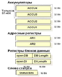
Рисунок 2.2 – Регистры CPU
Для создания
программ управления необходимо знать
назначение отдельных бит некоторых
регистров.
2.2.1
Master
Control
Relay
(MCR)
– Главное реле управления
MCR
– это «самый главный» выключатель,
управляющий подачей энергии на элементы
технологического процесса и, в случае
аварии, позволяющий их обесточить. В
Step
7 есть возможность в зависимости от
состояния MCR-бита
просто запретить прохождение ненулевых
сигналов на выходы контроллера, т.е.
заблокировать выходы.
Управление MCR
происходит посредством стека шириной
в один бит и глубиной восемь записей
(см. рисунок 2.3). MCR активизирован
(соответствует заблокированному главному
реле управления) до тех пор, пока все
восемь записей в стеке не станут равными
1.

Рисунок 2.3 – Управление MCR
2.2.2
Регистр STW
– Слово состояния
Выполнение команды
может изменить соответствующие биты
слова состояния CPU.
Эти биты могут использоваться как
результат операции, а также как информация
о результате выполнения той или иной
команды. Регистр STW
хранит 9 битовых признаков выполнения
операций (см. рисунок 2.4).

Рисунок 2.4 – Биты слова
состояния
-
Первичный опрос
Бит состояния /FC
управляет бинарной логикой внутри
логической системы управления. Шаг
битовой логики всегда начинается с /FC
= «0» и инструкции бинарной проверки,
первичного опроса. Первичный опрос
устанавливает /FC = «1».
Шаг битовой логики
завершается присваиванием бинарного
значения (например, единичной катушки
или назначения), условным переходом или
сменой блока. Эти элементы устанавливают
/FC = «0»;
-
Результат
логической операции
Бит состояния RLO –
это промежуточный буфер в операциях
бинарной логики. В ходе начальной
проверки CPU пересылает результат
считывания (проверки) в RLO, комбинирует
результат считывания с хранимым RLO в
каждое последующее считывание и сохраняет
результат, в свою очередь, в RLO.
Вы можете сохранить
RLO с помощью катушки / блочного элемента
SAVE в бинарном результате. При помощи
RLO управляются функции для работы с
памятью, таймеры и счетчики, а также
выполняются некоторые функции перехода;
-
Состояние сигнала
Бит состояния STA
соответствует сигнальному состоянию
считанного бинарного операнда. В случае
функций для работы с памятью значение
STA то же, что и записанное значение, или
(если операции записи не было произведено,
например, если RLO = «0» или MCR активировано)
STA соответствует значению адресованного
(и не модифицированного) бинарного
операнда.
В случае оценок
фронта FP или FN значение RLO перед оценкой
фронта записывается в STA. Все остальные
бинарные функции устанавливают STA = «1»;
-
Бит состояния
OR
Бит состояния OR
хранит результат выполненной
последовательной схемы или выполненного
условия AND
и показывает следующим обрабатываемым
параллельным схемам или функции OR,
что результат уже определен. Все другие
бинарные функции сбрасывают бит состояния
OR;
-
Двоичный результат
Бит состояния BR
(двоичный результат) помогает реализовать
механизм EN/ENO для вызовов блоков (в
сочетании с графическими языками). Вы
также можете самостоятельно устанавливать,
сбрасывать или считывать бит состояния
BR;
-
Переполнение
Бит состояния OV
отображает ошибки, возникающие при
выполнении математических команд или
команд сравнения для чисел с плавающей
точкой (REAL).
Бит OV
устанавливается этими командами после
того, как имела место ошибка (переполнение,
недопустимая операция, сравнение
невыполнимо). Бит состояния OV
сбрасывается после исчезновения ошибки;
-
Переполнение с
запоминанием
Бит состояния OS
хранит установленный бит состояния OV.
Всякий раз, когда CPU устанавливает бит
состояния OV, он также устанавливает бит
состояния OS. Однако, если следующая
корректно выполненная операция сбрасывает
OV, OS остается установленным. Это дает
возможность обнаружить выход за границы
диапазона или операцию с недействительным
числом REAL, даже позже по ходу программы.
Бит состояния OS
доступен для прямого чтения. Смена блока
сбрасывает бит состояния OS;
-
Кодовые биты
условия СС0, СС1
Биты состояния CC0
и CC1 предоставляют информацию о результате
функции сравнения, арифметической или
математической функции, побитовые
логические операции или о бите, выдвинутом
функцией сдвига. Вы можете непосредственно
считывать комбинации СС0 и СС1.
Соседние файлы в предмете [НЕСОРТИРОВАННОЕ]
- #
- #
- #
- #
- #
- #
- #
- #
- #
- #
- #
S7-200 Programmable Controller System Manual
Fatal errors cause the S7-200 to stop the execution of your program. Depending on the severity of
the error, a fatal error can render the S7-200 incapable of performing any or all functions. The
objective for handling fatal errors is to bring the S7-200 to a safe state from which the S7-200 can
respond to interrogations about the existing error conditions.
The S7—200 performs the following tasks when a fatal error is detected:
Changes to STOP mode
—
Turns on both the SF/DIAG (Red) LED and the Stop LED
—
Turns off the outputs
—
The S7-200 remains in this condition until the fatal error is corrected. To view the error codes,
select the PLC > Information menu command from the main menu bar. Table C-1 provides a list
with descriptions for the fatal error codes that can be read from the S7-200.
Table C-1
Fatal Error Codes and Messages Read from the S7- -200
Error Code
Description
0000
No fatal errors present
0001
User program checksum error
0002
Compiled ladder program checksum error
0003
Scan watchdog time-out error
0004
Permanent memory failed
0005
Permanent memory checksum error on user program
0006
Permanent memory checksum error on configuration (SDB0) parameters
0007
Permanent memory checksum error on force data
0008
Permanent memory checksum error on default output table values
0009
Permanent memory checksum error on user data, DB1
000A
Memory cartridge failed
000B
Memory cartridge checksum error on user program.
000C
Memory cartridge checksum error on configuration (SDB0) parameters
000D
Memory cartridge checksum error on force data
000E
Memory cartridge checksum error on default output table values
000F
Memory cartridge checksum error on user data, DB1
0010
Internal software error
1
0011
Compare contact indirect addressing error
1
0012
Compare contact illegal floating point value
0013
Program is not understood by this S7-200
1
0014
Compare contact range error
1
The compare contact errors are the only errors that generate both fatal and non-fatal error conditions. The
reason for the generation of the non-fatal error condition is to save the program address of the error.
478
Siemens s7 Error Codes, error number, error description and error cause.
| Error number: | Text: | Cause: | Remedy: |
| 34:178 | Block call invalid because interface was changed in the meantime. | With Step7 V5.0 the instance DB of the DB type is entered in the symbol list for an FB call. This is no longer permitted with Step7 V5.0. In this case the “Update Call” function doesn’t work. | Enter the instance DB of the FB type in the symbol list. |
| 34:4321 | Error in column 1, distribute the program in little
blocks. |
||
| 34:4355 | F Ze %2!06d! Sp %3!03d!: No plc type description found for called or addressed block
%4. |
The block called is not available. | The block is to be compiled before the call. |
| In the case of SFB/SFC calls, please copy into your offline database with the
SIMATIC Manager (block container). |
|||
| If the SFB/SFC is not available on the cpu addressed, then it should not be
called! |
|||
| 34:4461 | The block %4 that was called/used is protected or created by S7-GRAPH and cannot be generated. | You are trying to generate a KNOW_HOW_PROTECT block into an STL source. | The block named is protected and cannot be generated into an STL source. |
| 34:4469 | The declaration range of your formal parameter does not match the declaration range of the actual parameter, for example, no OUTPUT paramater from the actual end can be assigned to an INPUT parameter from the formal end. | It is not allowed, that an OUT variable of the calling function block is parameterized with the IN variable of the function block called. | We recommend first saving the data temporarily on a static variable. In a further network this static variable is parameterized with the IN variable of the FB called. The output variable of the higher-level block, the static variable and the input variable of the lower-level block must be of the same data type. |
| 34:4485 | The parameter assignments can be specified in any order in the ASCII source. The comments, however, are stored separately from the actual online block in the order entered. Thus, when exchanging parameters in the source, the order of comments might then be wrong. When the block is opened, the comments are then assigned incorrectly. In the worst case comments might even be lost. The following comments in the network are also affected, even when the exchanged parameters are not even commented. | If you have entered comments for parameters, then when assigning the parameters, please keep to the order in which the parameters of the block called are declared. | |
| Message appears when opening a VAT. The directory S7USS is missing
in the SIEMENSSTEP7 directory. |
Reinstall STEP 7. | ||
| 88:47 | Unable to reach the module %1 by means of the online interface that is set. | Programming device is connected to the MPI interface of the CPU. | Check whether the CPU is routing-compatible. If Not, then please set your MPI driver to PROFIBUS and connect up with the PROFIBUS DP. Then repeat the desired function. |
| Error number: | Text: | Cause: | Remedy: |
| 256:24 | Function open Environment is not implemetiert | Multiple start of the SIMATIC Manager | In the STEP7_V2/S7met directory delete the files S7CacheA.dat and S7ser.dat with Win95 Explorer. The ending .dat can be left out; depending on the options package, there is also an S7CacheB -E.dat |
| 256:26 | Internal OLE Error. | Not enough space on the hard disk, the database cannot be started. | Create space on the hard disk and set user-defined virtual memory. |
| Wrong DLL in Windows/System and/or wrong Registry entry. | Start program editor via Explorer and evaluate error message. | ||
| If the following message appears: “The file S7HRVERX.DLL is linked with the missing export S7OTBLDX.DLL: s7_set_password.”, then check whether the file ‘S7OTBLDX.DLL’ is in the Windows system directory. When implementing STEP 7 V4.02, you must delete this file from the Windows system directory. | |||
| If the following message appears: “The file S7KAFAPX is linked with the missing export OT5050R.DLL:4224”, check whether the OT5050R 2x is on the computer. Rename all except those that are in the S7BIN directory. | |||
| With V3.1 when printing | With V3.1 copy block comment into network comment. | ||
| WIN 95: the OLE was not installed properly when installing WINDOWS. | Delete Windows directory and then reinstall WINDOWS. | ||
| Message appears when opening a VAT.
The S7USS directory is missing in the directory SIEMENSSTEP7. |
Reinstall STEP 7. | ||
| 256:30 | SCL: Programming of S7 moduls. The object was
deleted. |
Error occurs when you export an SCL source, delete it in the SIMATIC
Manager and then import it again and compile it. |
Delete the block contained in the source in the SIMATIC Manager first and
only then compile. |
| 256:31 | This object was not found. | An object that fulfills the criteria specified is not available. The function triggered cannot be executed. The assignments in the OFFLINE database with regard to the HW configuration are no longer consistent. | You can reorganize the addresses with key combination |
| 256:32 | Not valid objects. | A link has obviously been lost. | In V2.1 projects the solution is to use “Save As with Reorganization” |
| 256:35 | Internal system error is not repairable. | ||
| 256:49 | The quoted entry is not in the registry by Windows or contains a not valid value. | Error occurred when downloading SDBs into a remote CPU via TeleService. The cause here was a bad telephone line connection (analog) (in the USA). After several attempts to set up an ONLINE connection, the SDBs could be transferred without this error message. An attempt was also made to achieve a higher transmission rate with the ONLINE connection. |
| Error number: | Text: | Cause: | Remedy: | |
| 256:53 | Internal error: Not valid pointer. | In PLCSIM an attempt was made to load the last simulation in PLCSIM via the menu item Simulation -> Last Simulation. Since the old project data (e.g. also block interfaces) has perhaps changed in the meantime, some of the data of the simulation originally created no longer matches the current project. | Create a new simulation via Simulation -> New PLC. The next time you run the last simulation the latest new simulation will be loaded without error message. | |
| 256:56 | There is an internal error in the system. | Project might be damaged. | Terminate application and restart. | |
| If the error re-occurs, restart Windows. | ||||
| STEP 7 V5.x: There is an internal error in the
system. |
Send project in to the Technical SIMATIC Customer Support. | |||
| 256:57 | There is an not repairable error in the system during the programming. The function can not be implemented. | ProjID.pro might possibly exist when dearchiving. | Copy/move ProjID.pro. | |
| 256:62 | Not repairable internal system error in refer to the
file “symlist.dbf”. |
Project might be damaged. | Computer might have crashed. | Save as … with consistency check or recreate the project. |
| 256:63 | Please see the remedies by errror number 258:15. | |||
| 256:68 | The object … cannot be edited because it is currently opened by another application or another user. | This message appears when you start the “File > Save as…” function together with the “With reorganization (slowly)” option if there are still applications open (e.g. Symbol Table) in the project which is being reorganized. | Before reorganizing, close all the applications in the project. | |
| 256:85 | SIMATIC Manager expects formatted names. | |||
| 256:89 | The version 513 of the objekt XR00001 is not
compatible in refer to the installed software. |
Legacy from V2 in XUTIL catalog | Delete the XUTIL directory in the project path | |
| 256:92 | The data can only be read. | This might be data, for example, from a project or library. The cause might be that there are no write rights for the directory or drive in which the data are located. | Make sure that you have the appropriate rights to access the drive or directory where the data is located.
Remedy: Using a virus scanner in Runtime mode can lead to faults. Do the virus scanning offline (i.e. at times when you are not working on your STEP 7 project) or disable the virus scanner on your computer. |
|
| The data is being processed by a different application or by a different
user. |
Save the modifications made in a different application and make sure that
no other user processes this data at the time in question. |
| Error number: | Text: | Cause: | Remedy: |
| The data are read-only. | You have copied a data backup of a project from a CD onto your hard disk and now cannot open this project. The reason for this is that all the files of the project have the attribute “write-protected” set. There are various ways of removing the write-protection from files. One such is described below. |
2. Open in the context menu the “Properties” and select “Security”. 3. Here you can allow the “Read” and other functions by “Permissions for Administrators”. 4. Click after on “Apply” and “OK”. |
|
| 256:93 | The rights of write is missing in the directory. | The directory in which the S7P file is located is write-protected. | Remove the write-protection from all directories that have to do with the
project. |
| If STEP 7 V4.x is concerned, then it might be that a file has not been deleted, which still specifies that the project is still on a write-protected drive. | Delete S7APROMX.TXT in the root directory of the project. | ||
| 256:94 | Problems with the offline folder. | This message may be due to the fact that the project has been dearchived on a computer and edited with an options package whose version is no longer compatible with the current STEP 7 version. | First of all check the versions of all the options packages installed on your computer which are required for editing the project. You may need to install one or other update (service pack) or upgrade (new version).
You can find information about compatibility with SIMATIC software packages for your STEP 7 version in Entry ID 18734363. Then make a copy of your project with “File > Save as…” and the option “With reorganization (slow)”. |
| 256:100 | Authorization of STEP 7 is not found. | No Basic Authorization installed. Error occurs when attempting to start an installed options package. Probably STEP 7 is only authorized as Mini. | Install Basic Authorization |
| 256:104 | Authorization of optional package is not found. | No user rights (authorization) found for the options software on drive C:. | Install the options authorization from the authorization floppy disk included in the delivery package. If you have lost the authorization (e.g. through a fault on the hard disk), you can install the emergency authorization to be able continue working for a limited period of time. You must then procure a replacement for the lost authorization during this limited time. |
| WIN NT: insufficient access rights. | To operate S7 software under NT you need at least main user rights. | ||
| 256:107 | The object specified could not be copied. There might not be enough space left on the data medium. Possibly the target directory is momentarily blocked by another application. | Press the “Yes” button to continue the copy or save operation for the remaining objects. The copied objects might possibly be incomplete or defective in the new environment. If you press the “No” button, the copy or save operation is aborted. |
| Error number: | Text: | Cause: | Remedy: |
| Possibly another STEP 7 application has opened the object to be copied and has thus blocked it. In this case, close all other STEP 7 applications and trigger the process again. | |||
| 256:111 | Access denied | Your have repeatedly loaded a program in the SPS and now it is not
possible to load the program again, also not after a new start. |
Start the service “Server” in the control panel. |
| 256:119 | There is no authorization for STEP 7. To operate this optional package, you require the authorization for “STEP 7 V4.x”. | No authorization installed or the path in which the STEP 7 project is located is too long. | Install the authorization or shorten the project path as appropriate. |
| 257:5 | One or more objects of a type cannot be represented. Unable to load the server ‘s7uvpomx.dll’ for _S7UV_LIST_CT-objects. Make sure that the required optional packages are installed. | The process variable server cannot be started. Installation problem with STEP 7. There must not be any incompatible version of WinCC installed on the computer. | Please check the version of the software package installed against the compatibility list. This is located in your STEP 7 directory as the file S7KOMP_x.PDF. x stands for the language: a=German b=English, c=French, d=Spanish, e=Italian. |
| Mixed installation, a V4.0 or V4.01 was installed before the installation
STEP 7 V5.x. |
Deinstall STEP 7 manually and then reinstall it.
See FAQ 189025 |
||
| Paths in Autoexec.bat are not set. | Edit Autoexec.bat so that the paths are set or not overwritten, as the case
may be. |
||
| One or more objects of a type cannot be represented.
Unable to load the server ‘s7hkdmax.dll’ for _S7H_DP_ETCR_INTGR_414_2_ROCF_CT- objects. Make sure that the required optional packages are installed. |
A file required by STEP 7 has not been found. Probably the project contains objects for which you need an options package that is not installed to process them. | Reinstall the DVA_S7 package. | |
| One or more objects of a type cannot be represented.
Unable to load the server ‘p7spumax.dll’ for _SIPROM_CONTAINER_CT-objects. Make sure that the required optional packages are installed. |
There is no authorization permitting you to integrate SIMATIC PDM in STEP 7. This authorization is an options authorization which has to be installed in addition to the basic authorization of SIMATIC PDM. | You must install the options authorization for integrating SIMATIC PDM in STEP 7. |
| Error number: | Text: | Cause: | Remedy: |
| One or more objects of a type cannot be represented.
Unable to load the server ‘s7jthomx.dll’ for _AUT_TH_AT-objects. Make sure that the required optional packages are installed. |
The S7 project to be opened contains an object that has been created with the options package Technological Hierarchies. This package is not installed or has not been recognized properly after an over-installation of STEP 7. | Reinstall the options package Technological Hierarchies. | |
| One or more objects of a type cannot be represented.
Unable to load the server ‘s7hk31ax.dll’ for _S7H_PLC315_2DPD_Modul_CT-objects. Make sure that the required optional packages are installed. |
Toolbox of SINUMERIK 840D is missing or is badly installed. | Reinstall the toolbox for SINUMERIK 840 D. | |
| The S7 project is opened with STEP 7 V5.x and the SINUMERIK 840D
toolbox is installed with version under V5. |
The SINUMERIK 840 D V4.x toolbox is incompatible with STEP 7 V5.
Please install the toolbox for SINUMERIK 840 D V5. |
||
| One or more objects of a type cannot be represented.
Unable to load the server S7HK31AX.DLL for _S7H_6ES7_315_1AF03_0AB0_CT – objects. Make sure that the required optional packages are installed. |
Your project contains objects that have been created with the options package C7_626P, but this options package is now not installed. | Please install the options packages concerned; in this case C7_626P. | |
| The message appears with each project you open, even if it doesn’t contain a C7_626P object. | In STEP 7 you have installed the options package C7_626P with an older version than the version of STEP 7. Please upgrade the package C7_626P. | ||
| One or more objects of a type cannot be represented.Unable to load the server ‘s7wb53ax dll’ for _S7H_6GK7_443_1BX00_0Xe_CT-objects. Make sure that the required optional packages are installed. | The NCM package is not installed and the S7 project contains corresponding objects. | Please install the options packages concerned; in this case the NCM options package. | |
| One or more objects of a type cannot be represented.Unable to load the server S7HK31AX.DLL for
_S7H_PLC314_Modul_CT_objects. Make sure that the required optional packages are installed. |
Toolbox of SINUMERIK 810 is missing or badly installed. | Reinstall the toolbox for SINUMERIK 810. |
| Error number: | Text: | Cause: | Remedy: |
| One or more objects of a type cannot be represented.Unable to load the server “s7hsl7ax.dll” for
_S7H_DP_PA_LINK_1_ETER_CT-objects. Make sure that the required optional packages are installed. |
The error is probably caused by the permanent upgrading of STEP 7. There are several older versions of STEP 7 one on top of the other. | Deinstall STEP 7 manually and then reinstall it. | |
| One or more objects of a type cannot be represented.Unable to load the server “p7ss357x.dll” for
_P7_FM357_6ES7_4AH00_0AE0_CT-objects. Make sure that the required optional packages are installed. |
|||
| One or more objects of a type cannot be represented. Unable to load the server S7HK31AX.DLL for _P7_PUSTCH_CPU
314_CT_objects. Make sure that the required optional packages are installed. |
|||
| One or more objects of a type cannot be represented.Unable to load the server S7HK31AX.DLL for _P7_POSTECH_CPU
314_CT_objects. Make sure that the required optional packages are installed. |
Either the tool MCU-Pit is not installed at all (product of Simodrive/Sinumerik) or the tool MCU-Pit V4.x has been installed in combination with STEP 7 V5.x. Warning: only the version V4.10 of MCU-Pit is released for STEP 7 V5.x. | Install the tool MCU-Pit V4.10. Also, in the directory Drive: SiemensStep7S7MET you must change the name of the file “p7skmcux.mv5” to “p7skmcux.met”. Then you must delete all the remaining
*.DAT files in this directory and restart STEP 7 (so that the metafiles can be recompiled). |
|
| 257:7 | Type of object is not declared | A file needed by STEP 7 has not been found. Possibly the project contains objects for which you need an options package that is not installed to process them. | |
| 257:8 | One or more objects of a type (%1!X!) cannot be represented. Make sure that the required optional packages are installed. | There is an object in the project that has to be parameterized with an S7 options package. This options package is not installed. | Install the missing S7 options package. |
| One or more objects of a type (%1!X!) cannot be represented. Make sure that the required optional packages are installed. | There is an object in the project that has to be parameterized with an S7 options package. This options package is not installed. | Please import the type file for the sensor module IF961-ENC4 configured on the FM456. | |
| 257:9 | The project contains objects of the optional package ‘xxxx’ that cannot be processed because the optional package is not installed or an outdated version is installed. | The project probably contains objects for which you need an options package that is not installed to process them, or a newer version of the options package. | Please install the options package concerned. |
| Error number: | Text: | Cause: | Remedy: |
| In the SIMATIC Manager create a copy of your project (with File > Save as…, Option “With Reorganization (slow)”). Here, the objects that belong to non-installed options packages are deleted in the target project. This error message will then no longer be issued when working with the copy of the project. | |||
| 257:24 | creat environment is not implemented. | SIMATIC Manager has been started double or computer has crashed. | With V2.x, delete the *.dat files in the S7met directory. In any case, procure
the latest correction version. |
| 257:26 | Not repairable internal system error. The link could
not be inserted. |
Message appears when you trigger the function “Display Reference
Data”. Links are distorted in the project. |
Use the function “Save as” together with the option “With Reorganization
(slowly)”. |
| Message also appears when forwarding a project in conjunction with the
symbol table. |
|||
| 257:79 | The project or parts of it are currently being edited by another application. | This message appears when you start the “File > Reorganize…” function if there is still an application open (e.g. Symbol Table) in the project which is being reorganized. | Before reorganizing, close all the applications in the project. |
| 257:90 | The project ‘%1′ contains errors in the internal data structure. | Project data damage by a crash/power failure on the computer.
With the “Details” button you can receive more information on the error, if available. |
1. Close all the STEP 7 applications except the SIMATIC Manager.
2. With the menu command “File > Save as (with reorganization (slow)) ” create a of the project which you can then continue to work with. Because of the faults in the existing project, this copy might not contain all the data of the original project. |
| 257:94 |
S7fupos: Internal error during save of data of server S7ombstx.dll. |
Inconsistent project.
Application FM 453 has registered errors when saving the machine DBs. A possible cause is the shortage of storage space on the computer. |
1. Close all the STEP 7 applications except the SIMATIC Manager.
2. With the menu command “File > Save as (with reorganization (slow)) ” create a of the project which you can then continue to work with. Because of the faults in the existing project, this copy might not contain all the data of the original project. |
| 258:1 | Unable to open project data %1. | IDB defined as GDB in the symbol table. | Define IDB correctly. In the case of V2.1, use Save as… for the project. |
| 258:17 | The directory C:SiemensSTEP7S7projtemp
exist already. |
The temporary SDBDATA directory created must have been destroyed by
the crash. |
In the directory [DRIVE]:SiemensSTEP7S7TEMP delete the directory
SDBDATA including subdirectories. |
| 258:20 | After archiving call File > Title Field and note the Title Field specifications. After dearchiving you can reestablish these specifications manually via File
> Title Field. |
||
| 258:15 | Some files or data blocks are write-protected and, therefore, the data can only be accessed on a read-only basis. This may be due to the fact that write access does not exist for the directory or drive where this data is located, or the block may have been saved as write-protected for reference purposes. | Ensure that you are authorized to access the drive or folder where the data is located. |
| Error number: | Text: | Cause: | Remedy: |
| There are still blocks (FCs, FBs, DBs and/or OBs) open and, as a result, the associated projects and directories cannot be deleted. | Close any STEP 7 (and WinCC flex) editors which are still open. We also advise you to close STEP 7 (and WinCC flex). Go to the Task Manager to check whether there are still any S7 processes in operation and, if so, close them. Then start STEP 7 again and delete the project via “File > Delete”. | ||
| If the remedies under the last above points do not help, close STEP 7 again and delete the project in the Explorer. You can find the folder for the saved project in Fig. 01 under
It is possible that the data areas of the HW Config, NetPro, Symbol Table or other STEP 7 components have not been released again completely after being closed. You should be able to delete the projects again after rebooting your PC. |
|||
| If the last remedy point does not help either and the project which you wish to delete is still present under the menu commands “File > Open…” and “File > Delete…”, some of the files in the SIMATIC software may be damaged. In most cases, the repair function on the STEP 7 CD can be used to restore the software status on your PC. | Otherwise, we recommend that you uninstall STEP 7 completely beforehand and also delete the directories in the Registry Editor. Follow the procedure precisely as described in our FAQ on “Complete Deinstallation of STEP 7 including all Software Packages”. You can find this FAQ in Entry ID 189025. | ||
| 275:5020 | There is an internal error in the file S7nlvblx.dll. | Save your entries and close the application. Switch your computer off/on and restart the application. If the error reoccurs, then please get in touch with your system administrator. | |
| 276:27 | No valid connection path between local and remote partners (e.g.
because of missing network connection or exhausted resources). |
HotFix 1 for SP2 clears this problem. This error is still in SP3 at the moment,
but will be cleared by another Add On. |
|
| 276:42 | Loopback – Connecting are not allowed! | Loopback connections are not permitted. You can specify an identical address as local and remote user address, but then SDB generation is rejected with an error message. | Problem (V4.02 and higher) is cleared with correction release K4.02.5. You can ignore this error message, because the communication functions despite this error message. |
| 276:5020 | An internal error occurred. (Call:
AUTReloadObject) |
||
| 288:48 | Unable to reach the module (z.B.) 413-2DP by means of the subnet assigned to the programming device/PC. | In a new project, for example, a hardware upload was made from the CPU to the PG. In the attempt to immediately download this upload, this error message appears. Problem: under Properties in Options -> Set PG/PC interface, 1 is preset as local user address on the MPI bus. But this does not match the address configured in the hardware upload and hence the error message. | Under Properties in Options -> Set PG/PC interface, set the local user address to 0 (or the one configured previously). |
| Error number: | Text: | Cause: | Remedy: |
| 289:2 | The data base is write-protected or there are not
enough memory. |
XREF with V2.1.0 + standard control | ->Correction K2.1.3 or higher |
| 289:25 | Two modules could not be translated back. | XREF with V2.1.0 + standard control | ->Correction K2.1.3 or higher |
| 289:35 | The selected button can not be executed for the selected menu. | You have selected a block folder and triggered printing. | This is how you print out the reference data for the blocks contained in the folder:
1. Mark the block folder. 2. Select the menu command Options > Reference Data > Display. In this way you display the reference data first. A check is made as to whether reference data is available and whether it is up to date. If necessary you can have the data updated. You can choose which table you want to have printed with which filter setting. |
| This is how you print out the all the blocks of the container with the editor with which they have been created: 1. Open the block folder.
2. Select all the blocks (e.g. via the menu command Edit > Select All). 3. Select the menu command File > Print > Object. |
|||
| 291:416 | The file is occupied by another application for writing. | Close all the applications that have opened the symbol table and restart the
function. |
|
| 291:416 | The symbol table is being by another process. | In the window that opens, the symbols are greyed out since editing is not possible. The Symbol Editor does not show any changes (it is not possible to save the table) and it is not possible to access the symbols. | Editing the entries in the symbol editor is still possible. Make the changes directly in the symbol table and save it. After saving the table, you can edit the symbols in the LAD/FBD/STL editor after closing and opening the dialog box again.
If you want to edit the symbols directly in the LAD/FBD/STL editor, close the symbol editor and reopen the dialog box “Edit symbols” in the LAD/FBD/STL editor. Editing is now possible. You can also simultaneously open the symbol table. Changes in other applications are automatically applied in the table. |
| Error number: | Text: | Cause: | Remedy: |
| 291:416 | The symbol table is occupied by another process | In this case you can no longer edit, delete or import the symbol table. The symbol table is not occupied by any other application for writing. You have stored the project locally on the hard disk. The same error is also displayed with the “Save with Reorganization” function of the project. | One possible cause of the error is that after a program crash of the symbol editor, temporary files are not deleted in the S7 data management. In order to control this, check your project:
1. In each project there is a “..YDBs” directory where all the symbol lists are stored. 2. Use Explorer to find files with the suffix .dbf tmp in this and all subordinate directories. 3. Terminate the STEP7 applications and delete these files. Then you can edit all the symbol lists again. It is imperative to make sure that you do not delete other files by mistake in the project, because this could destroy the project. |
| 1. First of all try closing all the STEP 7 applications including the SIMATIC Manager. If the symbol table is then opened via the SIMATIC Manager, an attempt is first made to clear any inconsistencies in the symbol table through a sort of internal “repair” service.
2. If editing the symbol table continues to be impossible, then please reboot your computer to make sure that all the STEP 7 applications have been closed. Then open the symbol table again. 3. If none of the above steps is successful, open the “..YDB” path mentioned above in the project directory. In this directory delete any files with the file name “deleted.txt” and “update.txt” and a size of 0 KB and any empty folders. You will then be able to edit the symbol table again |
|||
| 291:560 | Internal error: Incorrect object ID. | The symtabs function has failed – ambiguous entry in the symbol list for
FC names. |
Delete the line for the FC in the symbol table. |
| When calling an FB, a DB was assigned that is already assigned to
another FB in the symbol table. |
Assign a different DB in the call or correct the assignment in the symbol
table. |
||
| Copy out the symbol table, then open and close the block, and then copy
back the symbol table. |
|||
| 291:1392 | No symbol table found. No symbol could be
created. |
||
| 292:19 | Error by opening of a file. | The file either has no valid B+C287trieve format or it is damaged. | Replace the file or delete it. |
| 293:1 | The reference data could no be generated. | The data medium is write-protected. | Remove write-protection. |
| Under NT: possibly insufficient access rights. | You need at least main user rights. | ||
| 293:2 | The reference data could no be generated for the
SFC14 or the FC22. |
Use the function “Save as” together with the option “With Reorganization
(slowly)”. |
| Error number: | Text: | Cause: | Remedy: |
| 294:6 | Unable to copy the block %2. | The OBxy is not supported by the CPU. | This OBxy cannot and must not be downloaded into this CPU. You can possibly use another OBxy with a similar function, which is suitable for this CPU and then download it. |
| When programming an EPROM via an external prommer: the prommer
cable is plugged in incorrectly. |
Plug in the prommer cable so that the connector with the yellow sticker is
connected to the prommer. |
||
| Illegal command in the modul | The module FCxx could not be copied.
(D280) Error during compiling of module in the S7-300. |
This message appears, if your program has a marker (example M8000.0) which address is not supported in the CPU. Change the address and repeat the download. If the SF LED is not still erased after download, switch the CPU into STOP and after in RUN again. | |
| 294:23 | Unable to copy the block %2. Do you want to
continue the copy procedure? |
A block of this type already exists and it may not be overwritten. | Delete the equivalent block in the ONLINE database and repeat the transfer. |
| The automation system is in the RUN operating mode. | Put the automation system into an operating mode that permits copying. | ||
| SDBs can only be transferred in the STOP mode. | |||
| A block of this type and number is not permitted on the automation
system. |
Check whether a block of this type and this number may be copied onto an
automation system of the present type. |
||
| The block is using operands beyond the area of the CPU (e.g. EW 128
with S7-300 CPU). |
Check the block with reference to the addresses used whether they do not
exceed the permitted address area in the CPU implemented. |
||
| The block is using statements that are not realized in the CPU (e.g. ENT
with S7-300 CPU). |
Check the block with reference to the commands used based on the
operations list for the CPU implemented. |
||
| The block has to much local data (e.g. more than 256 bytes with S7-300 CPU). | When implementing an S7-300, you must reduce the local data area for this block. If you implement an S7-400 CPU, you can parameterize the necessary local data area for each run level. | ||
| Referenced block SFC, SFB is not permitted in this module. | Check whether the blocks that are to be downloaded are permitted on the
CPU concerned. |
||
| 294:27 | The block %2 is being processed by another application or another user at the moment.nDo you want to create the reference data for the saved version of the block? | Multi-users: the block specified is being processed at the moment by another application or by another user. You can create a copy of the last version saved or cancel the function. | If you are working with several colleagues on your S7 project, then it is recommended not to process this block without prior synchronization with your colleagues. |
| Single Users: the block is opened ONLINE as OFFLINE. | Close the block once; ONLINE or OFFLINE. | ||
| 295:17240 | |||
| 295:17248 | The order was interrupted to the TS-Adapter
because of transmission error. |
The initialization string is not correct or in this form does not work together
with the modem connected to the system. |
The initialization string in the TS adapter must be modified in the direct
operating mode so that it matches the modem. |
| Error number: | Text: | Cause: | Remedy: |
| On the system there is not a TS adapter but a PC adapter on the modem. The TS adapter has order number
6ES7972-0CA3x-0XA0 |
Exchange the adapter for a TS adapter. | ||
| Possibly the terminator on the PROFIBUS cable on the system side
(TeleService) is switched on. |
Switch off the bus terminator. | ||
| Possible the modem is sending too much information to the TS adapter so that it doesn’t get the CONNECT. (Occurs with V5 adapters) | Add W0 to the Initstring in the adapter (this suppresses the sending of extended data) | ||
| If you attempt to get connected via long telephone routes (abroad), then it might happen that some feedback messages have too long a runtime. | In TeleService under Options -> Settings -> Monitoring Times, change the value for Acknowledgment/Signal from Automatic to 5000ms / 4000ms. | ||
| 295:20484 | There is not installed a modem which is compatible with teleservice. | Install a suitable modem and set the modem to correspond with your configuration. Define the TeleService-specific properties of your installed modem in the menu command Options > Settings. | |
| 295:20486 | The TAPI-Order was closed with the error “Order
failure”. |
Basically communication between (local) PC and modem (via the serial
connection) is not correct or cannot even be started. |
Check the connection between the (local) PC and modem for both hardware
and software/driver faults. |
| Under Windows (Start –> Settings –> Control Panel –> Modems) an incorrect (or no) modem driver has been installed, which does not work in conjunction with the modem connected. | Install the appropriate modem driver for this modem. Also set this new modem in TeleService under Set Connection —> Modem (double-click the telephone book entry and then select the Modem item). | ||
| The wrong modem driver was selected under TeleService from the
selection list of modems that are already installed under Windows. |
Set the correct modem driver in the selection list. | ||
| The modem is not connected to a serial interface (or to the wrong one). | Connect the modem to the correct serial interface. | ||
| The modem is switched off. | Switch on the modem. | ||
| 295:32768 | TAPI-subsystem dues supply not expected error | ||
| ALLOCATED 0x80000001 | |||
| INVALDEVICECLASS 0x80000023 | |||
| 296:5309 | The variables of the instance data block which contain system attributes for messages are not aggree with the variables in the function block. | Clearance: check the function block and save it again if necessary. |
| Error number: | Text: | Cause: | Remedy: |
| 300:13 | Data basis could not be started. | Occurs as a consequence of message 256:94 and details 256:24/256:63 when executing the function “Reorganize” or “Save as… with consistency check”.
This occurs when a link is lost in the SYBASE database. |
The problem can be solved by deleting the file AMDBASE.LOG. Search in your project path for the log file of the SYBASE database (Amdbase.db). WARNING: if this file does not exist, then search the project for LOG or LOC files. |
| If you cannot find this file, then proceed as follows.
Restore the log file by entering the following start line via “Start/Run…” on the Windows user interface: dbsrv50 -f D:..Project path..ProjectAMOBJSAmdbase.db For example, for the “Deissw01” project on drive “C” in the standard STEP 7 project directory you enter dbsrv50 -f c:Siemensstep7S7projdeissw01AmobjsAmdbase.db The -f (force) switch has the effect that the DB file is recovered to the last status saved even if the necessary log file is not available. |
|||
| Occurs after dearchiving a project in STEP 7 V5.0. It has been created in
the version V4.02.x. |
|||
| 314:8 | At least one of the selected variables cannot be inserted at this point. | If, while you are processing a project in STEP 7 V5.3 which has been created with STEP 7 V5.1 and the error message described above appears in the LAD/STL/FBD editor when you insert a declaration line within an FB or FC, please check the names of the formal parameters in the declaration line for the block in question. This could be due to the fact that the name “Ret_Val” has been assigned to a formal parameter (IN, OUT, IN_OUT, STAT or TEMP variable). | In this event, the name “Ret_Val” must be renamed.
1. From STEP 7 version V5.2 onwards, users may no longer define the key term “Ret_Val” for the formal parameters. Version V5.2 still supported the entry “Ret_Val” in the declaration line in STEP 7 projects which were created in V5.1 and did not stop the block. 2. However, STEP 7 version V5.3 no longer supports the name “Ret_Val” in the declaration line, and the behavior described above occurs. |
| 724:21 | OM TD/OP: Data basis conflict of version
file: C:[step7-pfad][Projektname]S7TDOP.DBF has the version 50000. This program expected the version 10000. |
The versions of STEP 7 and ProTool are incompatible with those of the project. STEP 7 is V4.02.x and ProTool V5. | Upgrade STEP 7 to V5.x or deinstall ProTool and install V4.02 of ProTool |
| 1230:1001 | Opening of the station failed. | ||
| 1230:2001 | Unable to insert the object. | You have tried to slot an object that is not available (e.g. the header for an
object group or module class). |
Select an object (subrack, module, interface module…) from the hardware
catalog, which you can slot in the required location. |
| Error number: | Text: | Cause: | Remedy: |
| 1230:2009 | Changes cannot be made. Save your changes in other applications | The error message indicates that access to the object is not possible at the moment and that the object could not be blocked. This error message can have various causes:
1. The object is currently being processed by another application or user and has therefore been blocked. 2. There is insufficient memory available. |
The following steps permit you to process the object:
1. Save the changes made in all other applications and make sure that no other user is currently processing this object. 2. Make sure that there is sufficient virtual memory on your computer, see in this case the informations of the Readme file of STEP 7 by 3.2 Memory Requirements. Notes: Please consider the requirements of the actual installed STEP 7 software in refer to your PC, which are described in the readme file. |
| 1230:2015 | Creating the configuration data failed. | Hard disk is full. | Deleted all the unnecessary files on the hard disk. |
| No folder “…SIEMENSSTEP7S7TMP” available or the folder is write-
protected. |
Remove the write-protection from the folder “…SIEMENSSTEP7S7TMP” or
create the folder. |
||
| S7 program or M7 program container is missing. | Create S7 program or M7 program container. | ||
| Defective project? | Use “Save as… with reorganization” | ||
| The compilation (= creation of the configuration data) has been
interrupted. |
Reinstall STEP 7. | ||
| Error attempting to generate the configuration data. Message refers to the V2-projects by Save as with Reorganization. | Subnet addresses of different networks are identical. | Check the subnet addresses and make appropriate corrections in the case of identical subnet addresses. | |
| 1230:2016 | No changes can be made in this station. | No more modules can be inserted in the HW Config. | Use “Save as… with reorganization” for the project. Please see also the
instruction by the error message 256:92. |
| 1230:2018 | Another application made changes to your station. Close this station and re-open it. | Another S7 application has changed, for example, via network, the station currently being processed. The changed objects (subrack, modules, slaves, etc.) can no longer be displayed.
The station has been blocked for further processing. |
You can remove the block by closing the station and re-opening it. This makes the changes of the other application effective. |
| 1230:3000 | The system data could not be recreated because
the configuration is inconsistent. |
Check consistency. | |
| 2508:1099 | Error by programming of error diagnostic data for | Group message, behind it detailed messages are listed that occurred
during the last function executed. |
Please press the “Details” button and analyze the detailed messages. |
| Error number: | Text: | Cause: | Remedy: |
| 2517:5 | The start of an application has occurred an error. | Message appears when opening a HIGRAPH source. With the following software constellation:
STEP 7 V5.0 + SP 3 S7-HIGRAPH V4.01.1 S7 project created with S7-Higraph V5.x |
Cleared with K4.01.2. |
| 2665:4156 | Because of the changes made to the configuration, the configuration file for this SIMATIC PC station has to be created again with NetPro. To do this, use the NetPro menu command “Network > Save and Compile …” | ||
| 2760:11 | communication to higraph cannnot be accessed | ||
| 2775:777 | Address is not correct. | You have selected a user address that is already occupied. | Please select another address or connect your user to another subnetwork. |
| 2775:785 | The bit rate of 187,5 kbit/s for the modul MBK-P is
not supported in station SIMATIC 400(1). |
In STEP7 V5+SP3 and higher the baud rate must not be written with a
comma, e.g. 187,5_supp =1 |
Open and edit the file: enter ‘187.5_supp =1′ instead of ‘187,5_supp =1′.
Execute Options -> UPDATE CATALOG. |
| 2775:1829 | The data management of “Set PG/PC interface” can not save the requested value. | An attempt was made to save a parameter value in the database of the program “Set PG/PC interface”. This write procedure could not be concluded successfully. | |
| 2775:1860 | Caution: there are other active nodes (sender parameter assignment master) in station %1 which also have to be reloaded. | ||
| 3020:13 | File name entered is not valid, or Project is invalid,
if you attempt to open a project. |
This message appears when you stored your project on a network drive which is connected to the following path via the Internet Explorer or a logon script:
\computer.siemens.deshare) or However, this path cannot be found since the network connection is stored only symbolically in the registry. |
In order to be able to open your project, please connect the share (without the domain name) via
Note: If you have to enter the pathname via the IP address, you can establish a connection between the IP address and the computer name in the “hosts” file. The file can be found with the Windows path “system32driversetc” (Example: C:WINNTsystem32driversetc). |
| Error number: | Text: | Cause: | Remedy: |
| 3020:25 | Projects which are opened can not be archived. Make sure that in non STEP 7 application objects of the projects … are opened in the directory C:… | The reason for this error message are blocked files, which are also blocked though all the windows of editors and projects are closed. This is possible when the program is activ and the last access was to the archived project. Souch programs are not always to see as user window. | With WinCC or WinCC flexible will be started a SQL server which should be stopped. You will find this in the task bar. You will also find here icons of WinCC flexible, which are mini web or smart server. If you will stop these applications the archiving should be possible again. If not, then start the task manager and check in the process list whether the process “hmies.exe” is activ. If you delete this process, then the archiving should be possible again. |
| 3020:47 | This processing status is triggered by PKUnZip in different situations, in particular always when an existing project is overwritten during dearchiving and in the dearchiving options the entry “Overwrite objects with identical names” is not set to “All Files”. | In this – most common – case you can ignore the message. | |
| The archive file has not been created with PKZip. In particular archives that have been created with WinZip or “PKZip for Windows” and contain “long file names” can lead to this error. | Execute dearchiving with the archiving program used to create the archive. | ||
| The archive file has been created with a version of PKZip that is newer
than the version of PKUnZip that is installed on the computer. |
If you are using an old version of PKUnZip, install the latest version. | ||
| The archive file is damaged. Checksum errors (so-called CRC errors) have been detected for one or more files. Therefore the files could not be dearchived correctly. The cause of such checksum errors can in particular be:
damaged floppy disks, transfer errors when copying, in particular with network drives, file transfer or e-mail, or at the time of archiving the project or parts of it were still open. |
Try to get a good copy of your archive file. If this is not possible, you can try to save what is possible to save using the repair option of PKZip. Start the MS-DOS prompt and enter the command ‘pkzipfix archiv’. A file is created called pkfixed.zip – if pkzipfix can even identify the file as being ZIP- compatible. From the SIMATIC Manager dearchive the file pkfixed.zip instead of your original archive file. |
||
| The directories in the archive file have too great a nesting depth to be able to be unpacked under the specified target directory. PKUnZip cannot create any directories whose absolute path name is longer than 66 characters (from the drive designation to the ‘’ at the end of the path). | You can either dearchive the archive file with PKUnZip as follows: select the target directory for dearchiving the Root directory of drive. Close all the STEP 7 applications. Move the dearchived project directory with the Explorer to the location where the project is to be stored. Start the SIMATIC Manager and open the project via the “Browse” button in the “Open” dialog. Or you can use WinZip or PKZIP 2.50 directly at the required location. | ||
| The project already exists and individual files could not be overwritten when dearchiving, because they are write-protected. | Delete the file attribute “write-protected”. You can do this for example for individual files from the Explorer via the file properties, or you start the MS- DOS prompt, get into the project directory using “cd” and then enter the command “attrib -r /s”. Now repeat the dearchiving procedure.
D330 |
| Error number: | Text: | Cause: | Remedy: |
| The project already exists and individual files could not be overwritten when dearchiving, because the project or objects from the project are already open. | Close all the STEP 7 applications, restart the SIMATIC Manager and dearchive the project without opening the project to be overwritten beforehand. | ||
| 3020:49 | Unable to retrieve the project. The archive file might be defective. | The archive file has not been created with PKZip. In particular archives that have been created with WinZip or “PKZip for Windows” and include “long file names” can lead to this error. | Dearchive using the archiving program with which the archive was created. |
| The archive file has been created with a version of PKZip that is newer
than the version of PKUnZip installed on this computer. |
If you are using an old version of PKUnZip, then install the latest version. | ||
| The archive file is damaged. | Try to get a good copy of your archive file. If this is not possible, you can try to save what is possible to save using the repair option of PKZip.
1. Start the MS-DOS prompt and enter the command ‘pkzipfix archiv’. A file is created called pkfixed.zip – if pkzipfix can even identify the file as being ZIP-compatible. From the SIMATIC Manager dearchive the file pkfixed.zip instead of your original archive file. |
||
| The data medium or the directory in which the dearchived project is to be stored is write-protected, or you have no write authorization for the network drive. | Remove the write-protection or obtain write authorization for the network drive or dearchive the project into a different directory. | ||
| 3022:4121 | The FB is not available
The instance declaration is missing |
If during compilation in S7-PDIAG the mentioned error message, then it is probably the case that the S7-PDIAG blocks have also been copied from another STEP 7 during the copying procedure. This is not permissible, because the associated SFBs are then no longer up to date. | 1. Delete all SFBs. Open and save the FBs, FCs and OBs, which fetches the SFBs from the current library.
2. Now compile the blocks of the S7 program again with S7-DIAG, which should solve the problem. |
| Make the Check Block Consistency and compile the complete STEP 7
program. |
|||
| 3022:4121 | Invalid data type…”, | The error message is probably caused by an associated value with an invalid data type. Please also refer to the information in the Online Help of S7-DIAG concerning the data types that are valid for associated values. | Excerpt of the Online Help of S7-PDIAG:
“This associated value can have a parameter of the type BOOL, BYTE, CHAR, WORD, INT, DWORD, DINT or REAL from the E, A, M or DB areas. Likewise you can enter local variables of an FB to which an error definition is attached. These are extended upon generation according to the type instance concept. |
| 3280:503 | The registry database is not set up correctly for the
SIMATIC Manager. Install STEP 7 again. |
Installation is faulty. |
| Error number: | Text: | Cause: | Remedy: |
| 3280:708 | No objects can be copied or moved from projects/libraries of the current version to projects/libraries of version 2.x. | In STEP 7 there is no downward compatibility, the data management in V2 and >V3 is not the same, so blocks created with STEP 7 V3 or higher cannot be copied or moved into V2.x projects . | An attempt was made to copy or move an object from a version V3 project or from a version V3 library into a version V2 project or library. This is not possible because of incompatibility. |
| 3280:709 | The project or the library ‘%1′ is on a write-
protected medium. |
The project is either located on a write-protected floppy disk or you do not
have write authorization for the drive. |
Remove the write-protection if you want to modify objects in this project.
Please see the instruction by error message 256:92. |
| The project catalog was released in the Windows Explorer with read/write
access. |
Release higher-level catalog of the project (e.g. Step7S7Proj) for access
via network drive. |
||
| 3280:712 | File name entered is not valid. Project is invalid.
(If you attempt to open a project) |
Please see the informations by error message 3020:13. | |
| 3280:999 | The internet explorer is not installed in your PC. | STEP 7 V5 has been installed without the Internet Explorer and you are
trying to start the ONLINE Help. |
Please install the Internet Explorer V4.0 and then reinstall STEP 7. |
| The ONLINE Help was started and the Internet Explorer was installed
after the installation of STEP 7. |
Reinstall STEP 7. | ||
| 3531:1 | The diagnostic block could not be created. | Standard blocks in the program originate from the PLC and not from the library.
If the project has been created per upload by the PLC with an earlier version of STEP 7 or standard blocks have been copied from the PLC into the offline program, then the interface of the SFBs and SFCs in the project only has a Default Symbolic (parameter name = “IN0”, “IN1” etc. instead of symbolic names as described in the Help). In this case the same error is reported. |
Check your interface to the user block.
If your user program contains standard blocks with Default Symbolic, then please delete these SFBs and SFCs and reinsert them from the library. This corrects the interface of these blocks. |
| 3534:63 | While reporting a system error: an internal error has ocurred | To be able to generate the reference data without this message, proceed as follows:
1. Delete Diagnostics-FB49 and Diagnostics-DB49 from your STEP 7 Project resp. Block container. 2. Newly generate the reference data by selecting the block container and the menu task Extras > Reference data > generate. This message does no longer appear when generating reference data. |
You can regenerate the FB49 and DB49 in the Hardware-configuration as follows:
1. Highlight the CPU with the cursor. Under “Extras > reporting system errors… > Register: General”, you can now newly generate the Diagnostics- FB and the Diagnostics-DB. Finally, save and translate the Hardware configuration once more. 2. You can also newly generate the Diagnostics-FB and the Diagnostics-DB by means of “Save and translate” if you change the following setting: Under “Station > Properties … > Register: Settings” the option “Calling when saving and translating” has to be activated. |
| 3534:94 | Inconsistent of hardware configuration | The hardware configuration is either inconsistent or it was made changing which are not still save and compiled. | If it is not possible to compile the hardware configuration after this message, so make a little change in the hardware configuration. After it is possible again to save and compile. |
| Error number: | Text: | Cause: | Remedy: |
| 4050:1 | The resources file for this language is not in the directory in which you have installed this program. This is why the menus, dialog boxes and the online Help are in English in S7-PLCSIM. | Install the files that are required for the language desired. If necessary, reinstall S7-PLCSIM and select the required language. | |
| 4050:2 | Closing the subwindow “CPU” simultaneously closes the simulation session. However, you can close a CPU and start a new simulation session with another CPU. | Make sure that you always have on subwindow open in S7-PLCSIM. If you need more space on your screen, you can reduce the subwindow to icon size. | |
| 4050:3 | You can only change the MPI address if there are no applications linked
with the simulation. |
Close all the associated applications or disconnect from the simulation. | |
| 4050:4 | You can only ever have one simulated automation system activated. If you open a second simulated automation system, the one opened first is closed. If you want to continue the function, press “Yes”. Press “No” to cancel. | ||
| 4050:5 | You cannot exit S7-PLCSIM if there is still a connection set up to STEP 7 (e.g. SIMATIC Manager, variable table, program editor). STEP 7 indicates in a message that the connection to the CPU has been interrupted. You can then continue working offline. | Before exiting S7-PLCSIM you must close the associated applications in STEP 7 or clear down the connection to STEP 7. (In order to disconnect the SIMATIC Manager from S7-PLCSIM you must close both the online program and the offline program.) | |
| 4050:6 | When doing an overall reset (MRES), all the blocks are deleted and the
memory of the simulated automation system is reset. |
If you want to abort the overall reset, click “No”. If you wish to do an overall
reset, click “Yes” to continue the function. |
|
| 4050:7 | You have attempted to open a simulation that has just recently been used, but which is no longer available or cannot be found. S7-PLCSIM deletes the file name from the menu. | Find the simulated program using the menu command Simulation > Open PLC. If the program is no longer available, you must recreate the simulation. | |
| 4050:100 | The address you have specified has a format that STEP 7 does not support. | Enter the address in a format that is supported by STEP 7 (IEC or SIMATIC).
Examples: IEC: PIB0, PQB0, PIW2, PQW2, I0.0, Q0.0 C1SIMATIC: PEB0, PAB0, PEW2, PAW2, E0.0, A0.0, Z1 |
|
| 4050:101 | The value you have entered is not in the valid range for the selected format. For example, you cannot enter “FF” (hexadecimal value) in a field in which binary values are supposed to be entered. | Enter the value in a valid format or change the format of the field. | |
| 4050:102 | The value you have entered is not a decimal number. | Enter decimal number (e.g. 0, 1, 13). | |
| 4050:200 | Since there is a danger of changing an actual online program by mistake, you cannot communicate with “real” CPUs whilst the simulation is activated. | Close all the windows and applications that have been used in the simulation of your program before going online with an actual CPU. | |
| 4299:158 | No connection to FM355/455. | Old firmware on the FM. | Upgrade the firmware of FM. |
| Error number: | Text: | Cause: | Remedy: |
| 4431:2011 | The Authorisation for SIMATIC PDM is not installed. SIMATIC PDM could not be started. | Authorization permitting you to integrate SIMATIC PDM in STEP 7 is missing. This authorization is an option authorization that has to be installed in addition to the basic authorization of SIMATIC PDM. | You must install the additional authorization for integrating SIMATIC PDM in STEP 7. |
| 4502:298 | System error 33 | This meesage appears during the upload of the hardware configuration. It is possible that the load of the SDBs was not complete or incorrect. | Make a reset of the CPU modul and load the hardware configuration of the offline project again. |
| 4502:625 | An error occured while creating or interpreting the system SDB’s. “.
Error while creating systemdata………………………………. “. |
Regarding mentioned messages occur while saving and translating in HW config if the following applies:
2. Files with the extension .”err” will be deleted by some optimization programs – like e.g. TuneUp. |
Step7 has to be reinstalled or the missing “.err” files have to be copied from a different computer in order to be able to translate the hardware configuration again.
Attention: If you copy the files from a second STEP 7 installation, please make sure that this installation contains exactly the same STEP 7 version, the same servicepack and the same hotfix. |
| 4561:142 | The Authorisation for Standard pid Control is not
installed. |
.. | .. |
| Meldung von
Baugruppen |
|||
| D033 | Error of protokol | Job jam on the CPU. | In the HW Config increase the setting for the communications load for the
CPU. |
| D042 | Error during notice by module status of CPU400. | A PQW is being monitored. You cannot read back PQWs, the CPU then
reports this error. |
Monitor values with VAT and wait for new CPUs. |
| D043 | Error of data: The reference order is not available. | When controlling using Variable Monitoring it might happen that if too many control jobs are sent to the CPU, they are rejected by the CPU because its buffer is full. | Acknowledge the message and reduce the frequency of control jobs. |
| D062 | Resources error, job list is too full. | Please see the informations by error message 33:53346. | |
| D063 | Same as D064 | ||
| D064 | CPU 300 does not delete trigger events, the events then build up. | Switch CPU off/on. Problem cleared in the following CPUs: 6ES7 313-1AD01-0AB0
6ES7 314-5AE01-0AB0 6ES7 314-1AE02-0AB0 6ES7 315-1AF01-0AB0 6ES7 315-2AF01-0AB0 |
|
| D0AA | D0AA: The time limit is exceeded in process
operating. |
Communications load is too high. | Increase the communications load of the CPU from (default) 20% to 50%. |
| Error number: | Text: | Cause: | Remedy: |
| Message appears with the function “Control via VAT” to an address from the memory areas I, O, M, Timer, Counter, DB, which is not available in the broadest sense. | Please check the syntax of the address in the VAT, or whether the address is available in the system or perhaps not addressable (wiring fault, hardware fault). | ||
| D204 | D204: An error in the rules of coordinating has
occured. |
When attempting to load system data, in the background a variable table
was still open online. |
Close the variable table and retransfer the system data. |
| D20C | The OB can not be copied because the belong
layer is not available. |
Message comes from a CPU. An attempt is being made to transfer an OB
onto this CPU, which is not permissible. |
If possible, rename the OB or even delete it in the OFFLINE database and
retrigger the transfer. |
| D240 | An error in the rules of coordinating has occured. | Occurs if a block that is to be overwritten online is still being accessed. In
V4.01 with blocks in the call environment. |
Deactivate the setting “Call path with test/call environment”, then the block
can be downloaded. |
| An error in the rules of coordinating has occured. | Occurs when an object is accessed online (also VAT). | Close everything except HW Config. | |
| Error during opening of a empty document. Error
during opening of a symbolic table. |
An incompatible OPC Manager is installed. In the system path of
Windows vcf1.lic is responsible for this. |
Delete this file and the file vcf132.ocx and reinstall STEP 7. | |
| setup does not start with error message: in function “Sdbitmap”:unable to crate dialog make sure the _isres.dll is in _setup.lib | The _isres.dll is needed for switching languages. | Start Setup with the extension ol:b, then the Setup is forced to start in English. | |
| D280 | Error during compilation of a modul in S7-300. The module OB1 could not be copied. | This message appears, when the defined variable (marker, in- or output) in a module is not in the power range of the CPU. | Example, this message appears if the number of outputs is 8192 byte by the CPU and you have defined a variable outside of this range. Check the addresses with the definition of your variables. |
| D406 | The requested informations are not available. | Number of possible connections has been exceeded. | Check the connections and reduce where appropriate. Static connections
can be converted into dynamic connections. |
| EA 02 | The protocols of communication software (S7DOS) and the interface module (CP) are not compatible. | The customer has a STEP 7 V5+SP1 + recent PDM and a CP 443-5 Ext
> V2.7. The new RPC 7 protocol is used for data record routing between the CP and S7DOS. Unfortunately the CP up to version V2.7 does not support this function. |
Upgrade CP 443-5 to a version >V2.7. |
| The user is using the correct components STEP 7 V5 + SP2 + PDM, but
has a CP that does not have the DSGW. |
Check the configuration and replace the CP being used with a different CP
that has this function. |
||
| Set PG/PC interface | |||
| None | Error message by diagnostic: “Profibus/MPI Network diagnostic”.
Error: requested parameter could not be read from the register data basis! |
Firmware/driver error | This behavior no longer occurs in SOFTNET PROFIBUS S7 V5.0. |
| Message without numerical order | |||
| S7OTBLSTX | Incompatible versionen by S7OTBLDX.DLL and
S7OTBLSX.DLL. |
S7 applications are still running at Setup of STEP 7. | Please close all S7 applications and restart SETUP. |
| Error number: | Text: | Cause: | Remedy: |
| STEP 7 has been installed on a computer on which an S7 options package or version of ProTool /WIN CC is already installed which is not compatible with the version of STEP 7. | Please search for “S7OT*.*” on all your local drives and delete them. Then please restart the Setup of STEP 7. |